

Page 1
GUIDE TO INSTALLATION
OF THE
B&K
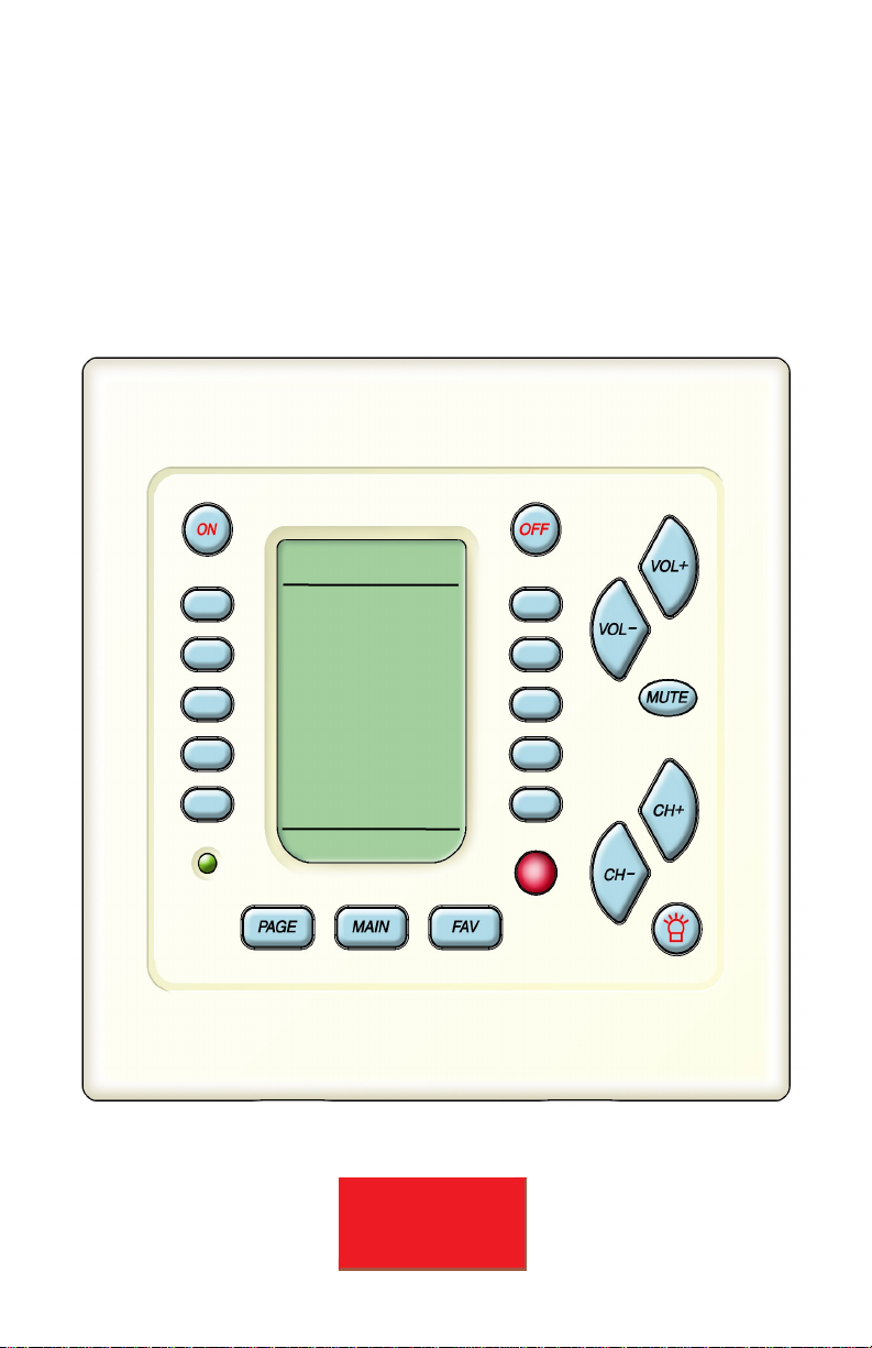
CK1.2 KEYPAD
SBIMPLY ETTER!
BK&
Rev B 0104
MAIN
IN 6 IN 1
IN 7 IN 2
IN 8 IN 3
IN 8 IN 4
FM IN 5
PAGE 1
Page 2

Thank you for choosing to install the B & K CK 1.2
Keypad for this system!
Please use this manual as a guide to connecting and mounting the Keypad.
The CK1.2 keypad is preprogrammed at the factory to initially operate
B & K CT products. It can be re-programmed using a Windows PC and the
accompanying CD. See the Keypad Programming Manual on the CD for
instructions on programming.
B&K Components, Ltd. sells its products through authorized dealers.
Buying from an authorized B&K Components, Ltd. dealer insures that you
have a FACTORY WARRANTY on your B&K Components, Ltd. product. A
warranty on B& K Components, Ltd. products is NOT VALID if the products
have been purchased from an unauthorized dealer or an E-tailer or if the
factory serial number has been removed, defaced orreplaced in any way.
Guide to Installation of the B& K CK1.2 Keypad
© 2004 B&K Components, Ltd. All rights reserved.
B & K Components, Ltd.
2100 Old Union Road
Buffalo, New York 14227
1.800.543.5252 In NY: 716.656.0026
Fax: 716.656.1291
E-mail: info@bkcomp.com
On the web: www.bkcomp.com
SBIMPLY ETTER!
BK&
Page 3

SBIMPLY ETTER!
BK
&
Table of Contents
Features and Benefits 1
Basic Controls and Displays 2
Rear Panel Connections 3
Programming Jack - Behind the Faceplate 4
Terminate RJ-45’s One to One 4
Standard CT610/310/600 System Configuration 5
Connecting To A CT610/310/600 6
Keypad Total Power Consumption 7
B & K PT5 Preamp- Perfect for Adding Zones 7
Keypads with Other B&K Preamp/Receivers 8
IR Repeaters for Any Brand of Preamp/Receiver 8
No Emitter for B & K Recievers & Preamps 9
Connecting Slave Keypads 9
Connecting Local TV’s and Devices 10
Mounting 11
Programming 11
White and Beige Wall Plate Included 11
Filling Out the Operation Manual for the Client 12
Specifications 13
Page 4

Page 1
Features and Benefits
Vast Programming Capacity
The CK1.2 can be programmed with 44 IR commands for each of up to 20
components or devices. Additionally, you can label the commands with user
friendly names that your client will find easy to use.
One Touch Automates Operation
The On, Off and all of the screen-labeled buttons can be programmed with
macros of up to 190 steps (steps can include IR commands, delays of .1 to
99.9 seconds, and Jumps to another Page).
Point Any Remote Control at the Keypad!
The integrated IR pass through sends the commands of any of your client’s
infrared remote controls to components connected via flashers. If your client
wants to use a remote control in any room, they simply point it at the B & K
keypad.
Automates Local TV’s and the Central System
!
By connecting a flasher directly to the Keypad, you can program the IR
commands and Macros to automate TV’s and components placed in the
zone.
Two Way Communication With B & K Multi-Zone Receivers
The keypad displays the status of the zone it controls in two ways:
1. The green status LED indicates when the zone is on or off.
2. The keypad displays the name of the currently selected source, regardless of how a new source is selected (by a remote control, the front
panel controls or the keypad itself).
Multiple Keypads within One Zone
You can daisy-chain keypads within one zone. All keypads will correctly display the zone power status and the selected source.
Ultra-Fast Programming via PC Software
A vast database of more than one thousand brands instantly programs IR
Codes for most components, B & K Batch Learning does the rest in a fraction of the time of any other system.
Retains Programming Through Power Failures
Your programming is safe in the event of a power failure of any length. The
Non-Volatile Flash Memory keeps the program intact.
SBIMPLY ETTER!
BK
&
Page 5
Page 2
SBIMPLY ETTER!
BK
&
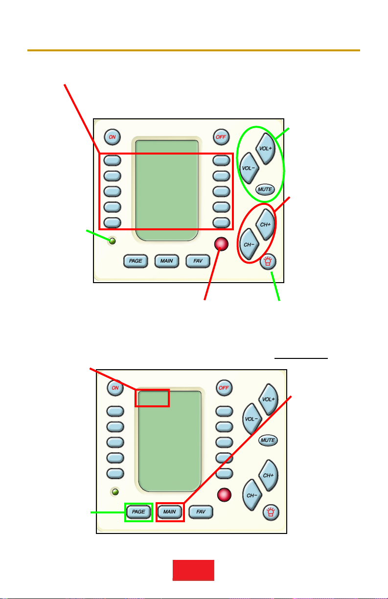
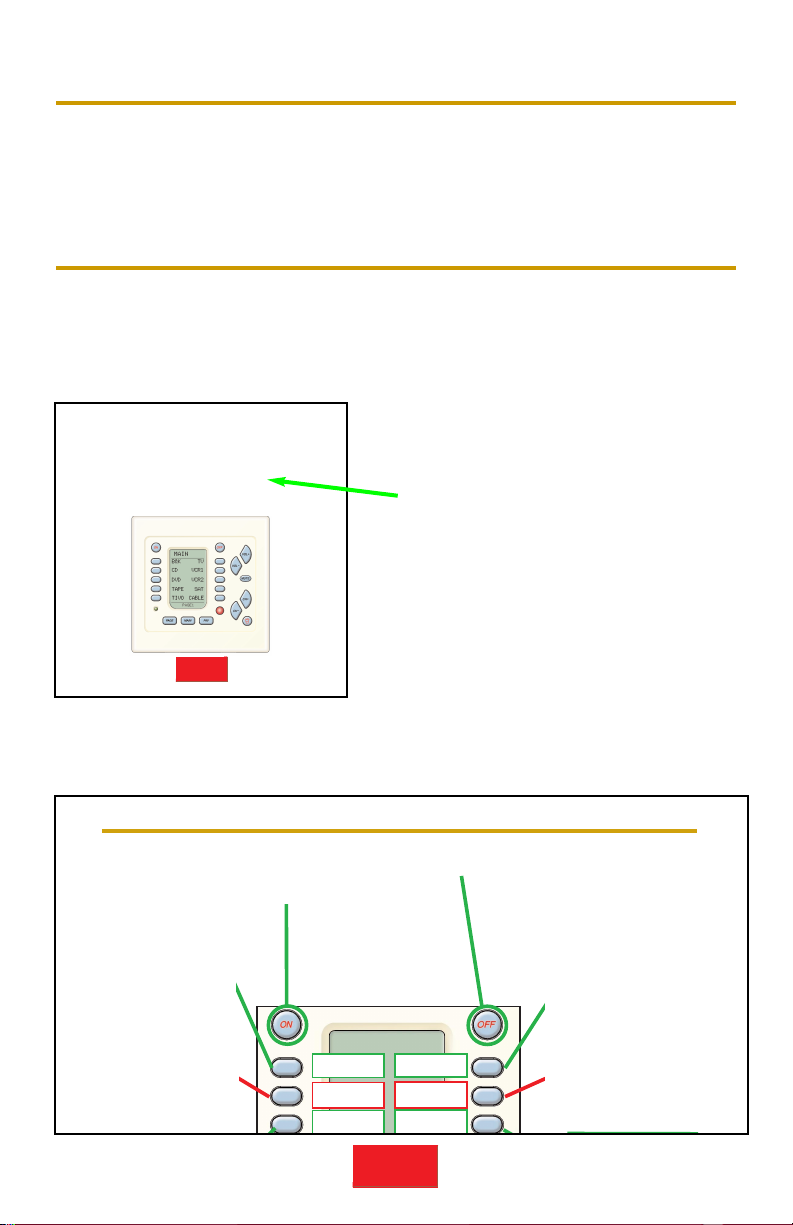
Basic Controls and Displays
Volume/Mute
Buttons
control the
level of the
sound.
Change
Buttons
Change to the
next channel,
chapter, song or
B & K sound preset; depen-ding
on the selected
activity.
Power LED
Lights up
when this
Zone/Room is
ON.
LCD Buttons - Labels on the Screen change depending on what activity
has been selected. For example, when CD is the activity,
you’ll see the labels change to Play, Stop etc. so that the
CD can be controlled.
MAIN
CD NEWS
SAT JAZZ
DVD CLASS
TAPE ROCK
HOUSE AUDIO
PAGE 1
Backlight Button
lights the keypad
display & recalles
status feedback on
CT
products.
Remote Control Target
conceals an IR (Infrared) Sensor
which relays commands from hand
held IR remote controls to components connected to Flashers.
Page Button
press to display any additonal pages of
functions.
Main Button The Main button always
returns you to
the Main Menu
so that you
can select a
new device
(activity) or
turn the system on or off.
MAIN
CD NEWS
SAT JAZZ
DVD CLASS
TAPE ROCK
HOUSE AUDIO
PAGE 1
Screen Title Displays what
Source is
selected ( i.e.
device or activity like “CD” or
“SAT”). Main
indicates the
Main Menu for
selecting a
new device or
activity.
Page 6

Page 3
SBIMPLY ETTER!
BK
&
Rear Panel Connections
SLAVE (OUT)
Connects to the MASTER (IN) of
any other same-zone keypads via
an RJ-45 plug.
ALTERNATE MASTER (IN)
The Alternate Master has two purposes
in most systems:
1. You can use it instead of the MASTER (IN) when the cable from the
CT610/310/600 is not terminated in
an RJ-45 plug.
2. You can terminate a flasher for a
local TV or component to terminals
2 and 4.
MASTER (IN) Connects to the
CT610/310/600 via a standard
4 Pair Twisted cable (typically
referred to as CAT 5 cable)
terminated with an RJ-45 plug.
Master Pin Out
1 - +12VDC IN
2 - KEYPAD DATA OUT
3 - GROUND
4 - N/C
5 - RS-232 RECEIVE INPUT
6 - GROUND
7 - STATUS IN
8 - +12VDC IN
Slave Pin Out
1 - +12VDC IN
2 - KEYPAD DATA OUT
3 - GROUND
4 - N/C
5 - RS-232 SLAVE OUTPUT
6 - GROUND
7 - STATUS IN
8 - +12VDC IN
Page 7
Page 4
SBIMPLY ETTER!
BK
&
Programming Jack - Behind the Faceplate
The face plate is removed by prying up from the two screwdriver tabs at the
base of the keypad. Once removed, the Programming Jack is revealed:
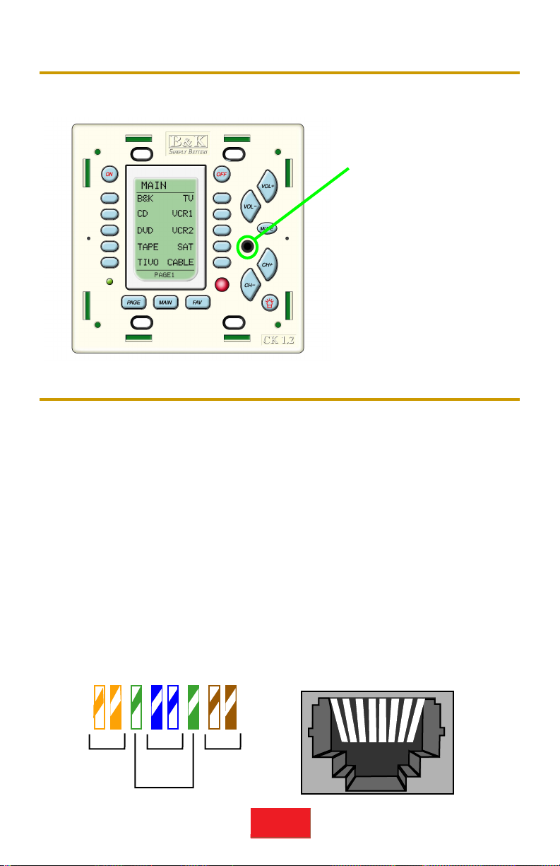
Terminate RJ-45’s One to One
You can terminate the RJ-45’s using any color code, just connect them
straight through; exactly the same color to pin on each end of the cable.
Standard pre-terminated LAN (Local Area Network) cables work fine.
For convenience, the EIA 568B color scheme is listed below. The first color listed in the color pair is the dominant
color of the wire. In other words, White/Orange is a white wire with orange stripes. N/C = Not Connected
Programming Jack
Connect to a laptop PC via
the Serial cable included
with the CK1.2 keypad. If
your PC does not have a
serial port, utilize a USB to
serial converter.
CK1.2 MASTER[IN]
1. +12VDC IN
2. Data Out
3. Ground
4. N/C
5. RS-232 Receive
6. Ground
7. STATUS IN
8. +12VDC IN
RJ-45’s Both Ends
1. White/Orange
2. Orange/White
3. White/Green
4. Blue/White
5. White/Blue
6. Green/White
7. White/Brown
8. Brown/White
CT-610 Zone Control
1. +12V(Extra)
2. Data In
3. Ground(Extra )
4. N/C
5. RS-232 Xmit
6. Ground
7. Control Out
8. +12V
12345678
12345678
Pair 2
Orange
Pair 1
Blue
Pair 4
Brown
Pair 3
Green
RJ-45 Jack Pin #’sEIA-568B Pinout
Page 8
Page 5
SBIMPLY ETTER!
BK
&
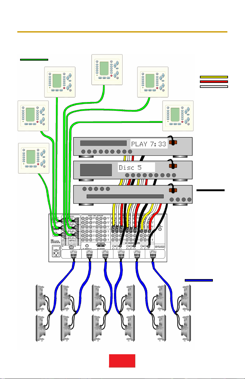
Standard CT610/310/600 System
Keypads connect to the Zone Control
Connectors on the CT610/310/600 via
CAT 5 cables.
IR Flashers
for A/V components are
connected to
the IR output
corresponding to their
A/V Input #.
The receiver power
amplifiers connect to
each Zone speakers
via your favorite
speaker wire.
A/V components connect via standard
audio and video
cables to the numbered inputs.
Page 9

Connecting To A CT610/310/600
Keypads connect to the CT610/310/600 at the Control terminals. There is a
set of five terminals for each of the hardware Zones labeled A-F on the
CT610/600 and A-C on the CT310.
You can terminate the Keypad cables to the Control terminals in one of two
ways:
1. If your cables are already terminated in RJ-45 plugs,
order the accessory “Terminal Block to RJ-45 Adapter”
(P/N 21419) separately from B&K.
Plug the RJ-45 plug into the adapter
and screw the adapter in place on the
CT610/ 310/600. Be sure to match the
labels on the back panel to the labels
under the pins of the adapter.
AND/OR
2. You can strip the keypad cable and terminate five of the wires to the five
terminals per Zone. If you are using a CAT 5 cable connected to an RJ-45
at the Keypad, there are extra connections for Ground and 12V. These can
be left unterminated (though it does no harm to connect them). It is not
important that use any particular color scheme, only that you connect one to
one as described here:
Page 6
SBIMPLY ETTER!
BK
&
MASTER[IN]
1. +12VDC IN
2. Data Out
3. Ground
4. N/C
5. RS-232 Receive
6. Ground
7. STATUS IN
8. +12VDC IN
ALTERNATE MASTER [IN]
1. +12VDC IN
2. GROUND
3. RS-232 RECIEVE
4. KEYPAD DATA OUT
5. STATUS IN
CONTROL ZONE A-F
1. +12VDC IN
2. GROUND
3. RS-232 XMIT
4. DATA IN
5. CTRL OUT
CONTROL ZONE A-F
1. +12VDC IN
2. GROUND
3. RS-232 XMIT
4. DATA IN
5. CTRL OUT
CK1.2 Keypad CT610/310/600
Page 10

SBIMPLY ETTER!
BK
&
Page 7
The B & K PT5 Preamp — Perfect for Adding Zones
The superb sounding B & K PT5 Preamp incorporates a keypad Control terminal and an IR output for flashers. A simple system would connect like this:
Keypad Total Power Consumption
The CT610/600 Control 12VDC Outputs can support a Maximum of 26 keypads total. 13 keypads to each vertical array of three zone control connections. Thus, a CT310 can support a maximum of 13 keypads. If you are
supplying power to relays, screens or sensors, these must be counted too.
Each keypad consumes 75mA.
Each of the zon e/control cards of the CT610 are identical to the single card of the
CT310. Zone/Control cards incorporate 3 zone keypad/sensor connectors and 1
common control output. The total power consumption of all devices attac hed to one
card cannot exceed one amp.
Fam Rm KP 75 mA
Fam Rm Sensor 50 mA
Fam Rm Screen relay 200 mA
Kitchen KP 75 mA
Bedroom KP 75 mA
BedroomTV lift 200 mA
_______
Total 675 mA
Liv Rm KP 75 mA
Patio KP 75 mA
Den KP 75 mA
Den Sensor 50 mA
_______
Total 275 mA
Multiple Flashers are connected in
Series for consistent level.
Two keypads can
be powered by
the PT-5 (Master
to Slave).
+
-
Note: Currently, the CK1.2 keypad does not display input changes made by remote control or the front panel
of a PT-5 (only the CT610/310/600 Multi-Zone receivers activate this feature of the CK1.2 keypad).
Each of the zone/control cards of the CT610/600 are identical to the
card of the CT310. Zone/control card incorporate 3 zone keypad/sensor connectors and 1 common control output. The total power consumption of all devices attached to one card cannot exceed one amp.
Page 11

Page 8
SBIMPLY ETTER!
BK
&
Keypads with other B& K Receivers and Preamps
The CK1.2 Keypad can be easily programmed with the commands for all
remote controlled B & K receivers and preamps. Because of B & K’s elegant
all discrete code architecture, the CK1.2 will automate and delight owners of
any B & K receiver or preamp. You can simply connect the keypad to any B
& K receiver or preamp directly to control just the B& K (with the addition of
an inexpensive 12VDC power supply). However, the best way to connect is
to utilize an Infared Repeater system to connect your B & K keypads to both
your B & K receiver/preamp and your other brand sources and devices.
Infrared repeater systems are available from reputable manufacturers like:
Infrared Repeaters for Any Brand of Receiver/Preamp
Infrared repeater connecting blocks enable you to use the CK1.2 with any
brand of infrared remote controlled receiver or preamp. However, infrared
repeaters do not support RS232 communications, so a change in source
made via the receiver’s original remote control will not update the screen of
the CK1.2 the way it does when connected to a B & K CT610/600 or CT310.
Thus, in systems like this, the best advice is to always use the keypad to
change sources, not the remote control to keep things “in sync”. All Infrared
repeaters incorporate three conductors that connect to the CK1.2 keypad.
These connect as follows.
IR R
EPEATER ALTERNATE MASTER [IN]
1. IR DATA
2. Ground
3. 12VDC+
Repeaters are typically shipped with a power supply of about 500ma.
Should your system require more than five keypads purchase a larger 912vDC unregulated power supply.
Audioplex and Xantech infrared repeater connecting blocks incorporate an
additional feature: A jack that enables a fourth conductor to send 12VDC
status when the preamp/receiver is on. This requires that your
preamp/receiver have a the switched outlet on the rear. If it does, you simply plug a 12VDC power supply in the outlet and connect to the status input
on the repeater. You then connect a fourth conductor to each CK1.2 keypad
to the Status In connector.
Niles Audio www.nilesaudio.com
Xantech www.xantech.com
SpeakerCraft www.speakercraft.com
Audioplex www.audioplex.com
Sonance www.sonance.com
These brand and/or product names are trademarks or registered trademarks of their respective companies or organizations.
4. KEYPAD DATA OUT
2. GROUND
1. +12VDC IN
Page 12

Page 9
SBIMPLY ETTER!
BK
&
Connecting Slave Keypads
Each zone should have only one CAT 5 cable home run to the
CT610/310/600. When rooms interconnect and open to each other (for
example: interconnecting family room, kitchen, dining areas are common in
many homes) you may opt to expand a zone to include several rooms.
Each room can have it’s own keypad. Many keypads may be connected in a
daisy chain to the single Master keypad, which is the keypad connected to
the CT610/310/600. There is no programming necessary, all of the keypads
may be programmed with the same configuration (in rooms where a local
TV is present, you should program a slave keypad differently to control the TV).
The main system connects to the Master keypad via the MASTER [IN].
From the Master Keypad’s SLAVE[OUT] connect to the Slave keypad’s
MASTER [IN]. You can continue the daisy-chain to as many keypad’s as
you want. However, keep in mind that each keypad consumes 75mA of
power. See page 7 for more information on Total Power Consumption.
No Emitter Needed for B & K Receivers and Preamps
B & K receivers and preamps manufactured in the last ten
years incorporate a Zone A IR input which will accept IR
commands without the addition of a front panel emitter.
Utilizing a standard 1/8” mono mini-plug (3.5mm), you can
connect directly to an IR repeater as follows:
Niles: Do not use Flasher Outputs!
Tip to DATA OUT (Active High output)
Ring to GND (Ground)
Xantech, SpeakerCraft, Audioplex, Sonance
and all others connect to the standard Emitter Outputs:
Tip to Emitter + Ring to Ground
Page 13

Page 10
SBIMPLY ETTER!
BK
&
Connecting A Local TV or Device
Every keypad can control a local TV or even a local system of components
in addition to the components in the main system. A two conductor cable
should be run from the Keypad location to the local component location. As
many as four infrared emitters can be wired to a keypad by connecting in
SERIES as shown here:
To Main System
Series
Connections
Multiple Emitters should
connect in SERIES!
When connecting emmitters
directly to the keypad, additional resistance is needed,
usually between 100Ω to
500Ω depending on the
length of the run. Series
connections are recommended!
There is no problem
connecting to the Main
system via the ALTERNATE MASTER [IN]
instead of the MASTER
[IN] as shown here.
Simply connect in parallel with the Local TV
emitter cable.
Wiring requirements for emitters
are loose. Standard 2 conductor 16
gauge speaker wire is ideal for
long runs from the keypad to a
Local TV or device. Utilizing CAT 5
cable will also work well.
Emitter
For
DVD
+
-
+
+
+
-
-
-
Emitter For TV
Page 14

Page 11
SBIMPLY ETTER!
BK
&
Mounting
After connections are made, the CK1.2 installs into a two gang J-Box or an
open backed double gang trim ring with the enclosed screws. If you opt to
use a closed J-Box, it must be a minimum of 2 3/4” deep to accomodate
standard RJ-45 plugs in the rear. If you plan to utilize the ALTERNATE
MASTER connections and DO NOT PLAN to add a slave keypad, you could
install the CK1.2 in a considerably shallower J-Box (2”). It is fastest and
easiest to mount the keypad in an open backed trim ring as shown here:
Programming
Use the included CD-Rom to install B & K’s Keypad editor on your windows
PC. CKEditor runs on Windows 98, ME, 2000, XP and XP Pro. It is usually
best to do all programming in front of the components with a CK1.2 connected to your laptop’s serial port.
To program, simply open the program, go to the
Program Menu and work your way through the
seven programming steps, test and download to
each keypad.
If you have questions, go to the Help Menu and
utilize the Keypad Programming Manual.
IMPORTANT NOTE - The CT610/310/600 sends status communications
to zone keypads whenever a zone source change
is made. Program the CT610/310/600 with your
Main Menu positions first, using the worksheets
in your CT610/310/600 installation manual.
Otherwise, the CT610/310/600 will command the
keypads to jump to the wrong page after a source
change!
Often the best solution to mounting a B & K keypad are the mounting plate brackets for Low
Voltage Class 2 devices made by Caddy, B-Line
etc. Of course, enclosed J-Boxes can be used,
they must be deep enough to accomodate the
depth of the RJ-45 connectors plugged into the
rear of the keypad (2 3/4”).
Page 15
Page 12
SBIMPLY ETTER!
BK
&
White and Beige Wall Plate Included
Once programming is complete and downloaded to each keypad, finish the
installation off by installing either the white or the beige wall plate. The wall
plate simply snaps into place, first from the top, finishing with the bottom.
Filling Out the Operations Manual for the Client
Before training your client, it is best to fill out each room’s Operation
Manual.
On the cover page of the manual,
write in the Client’s name for the
room the keypad controls.
In the center spread, write in the names of each device/activity and
clarify anything that might confuse the client.
SBIMPLY ETTER!
BK
&
Kitchen
TV, DSS and Sound
System On You are
watching DSS!
CD
FOOD
COOK
TAPE
Turns the Kitchen OFF!
(TV and Sound System
only!)
TV is turned off if
on, CD is turned
on and
starts playing.
TV and DSS are
turned on if off,
DSS is tuned to
the Food channel!
TV and DSS are
turned on if off,
DSS is tuned to the
Cooking channel!
TV is turned off if
on, Tape is turned
on and starts
playing.
AUDIO/VIDEO SYSTEM OPERATION
IN YOUR
_____________
WITH Y OUR B & K CK1.2 KEYPAD
Your Main Menu Button Descriptions
ON Button: _________________
_______________
MAIN
OFF Button: ______________
______________
Page 16

SBIMPLY ETTER!
BK&
B & K Components, Ltd.
2100 Old Union Road
Buffalo, New York 14227
1.800.543.5252 In NY: 716.656.0026
Fax: 716.656.1291
E-mail: info@bkcomp.com
On the web: www.bkcomp.com
CK1.2 Keypad Specifications
Compatible B& K products
AVR507/ 505, REF50,
PT5, CT610/310/600
Operating Voltage and Current 12VDC @ 75mA
Master Inputs 1 RJ-45, 1 Pheonix 5pin
Slave Output 1 RJ-45
IR Pass-through 1
Local Flasher Capability Use in line Resistance
Installation Requirement Standard Double Gang
Keypad Dimensions
Height (Faceplate)
Width (Faceplate)
Depth
4.7”
4.75”
2.3”
 Loading...