

Page 1
Page 2

ENJOY YOUR BOOKS
PLEASE VISIT OUR STORE FOR EVEN MORE GREAT
STUFF!
COPYRIGHT NOTICE
ALL MATERIALS INCLUDING CD/DVD AND PDF
FILES ARE COPYRIGHTED
VON
WALTHOUR PRODUCTIONS AND MAY NOT BE
REPROD UCED, COPIE D OR RESOLD UNDER ANY
CIRCUMSTANCES. YOU MAY HOWEVER MAKE A
COPY FOR YOUR OWN PERSONAL BACKUP.
MATERIALS ARE FOR PERSONAL USE ONLY.
IF YOU PURCHASED THIS FROM ANYWHERE BUT
FROM US PLEASE NOTIFY US IMMEDIATELY SO
THAT WE MAY CHECK IF YOU PURCHASED FROM
AN AUTHORIZED RESELLER SO WE CAN LET YOU
KNOW IF YOU NEED TO RETURN FOR FULL REFUND
FROM AN UNAUTHORIZED SELLER.
THANKS AGAIN AND PLEASE TAKE THE TIME TO
VISIT OUR STORE.
ATTE NTION! EVERYTHING ON S ALE NOW!!
Page 3
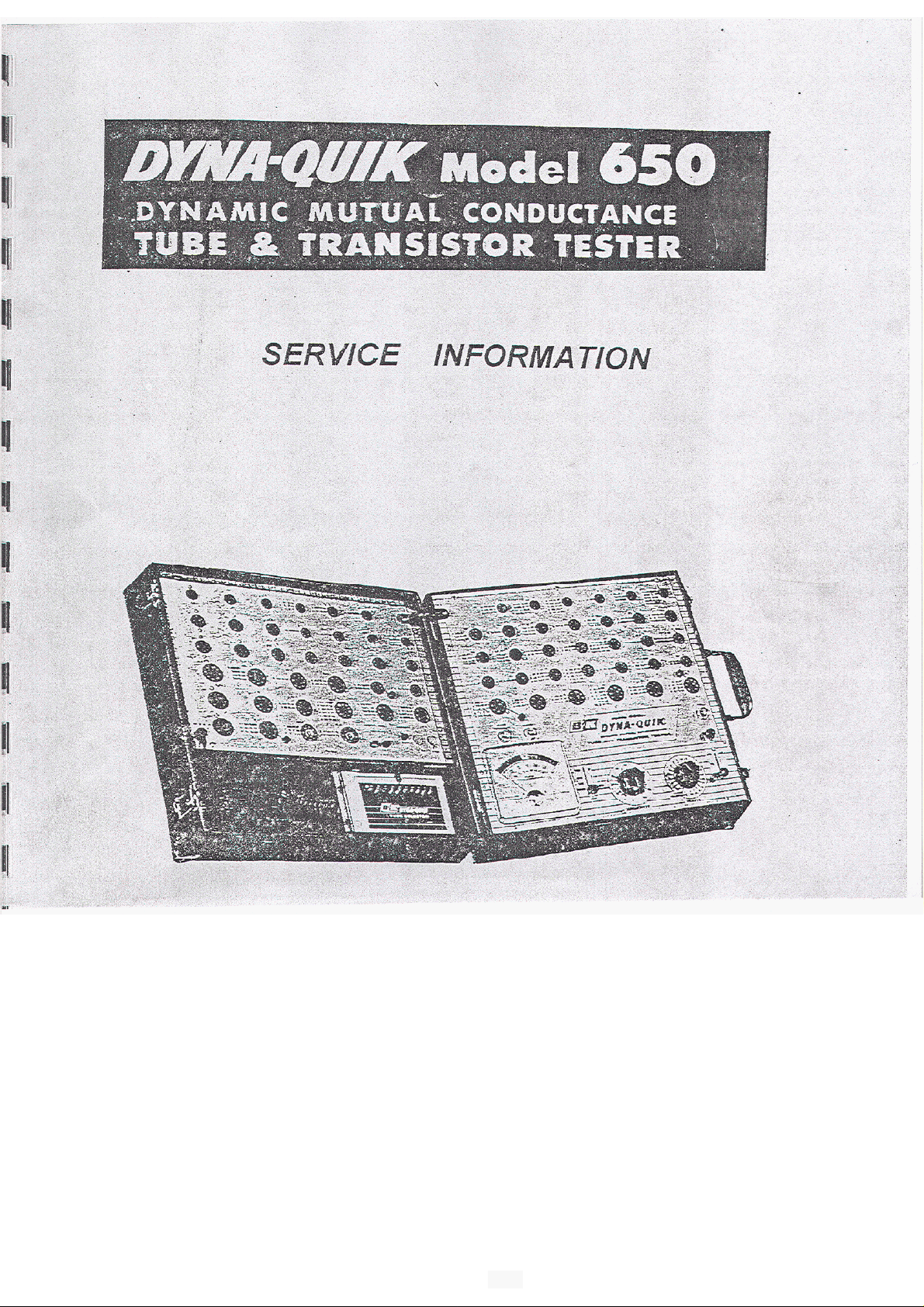
B&K MODEL
TUBE
TESTER
OFFICIAL INSTRUCTIONS
"A"
Circuit
The Model 650isa dynamicmutual conductance tube
in twochassis.The
of
the necessary voitages requiredtotest
sockets.
voltages required for the auxiliary socket panel appearonthe
contact conneetor locatedonthe bridge panel
this
lower-hand contact wouldbemarked
readings from bottom to Theleft
the
lower left-hand corner and read from bottomtotop,
These correspond to the
The schematicdiagram allof the necessary voltagesto troubleshoot
this instrument. All voltages measured areopenedcircuit voltages
measured
been made with
ground.
With test switch in test
contact
the main panel sitting upside down and the meter closest to you,the
with this service information
with
115
a
first
chassis consistsof the main panel which contains
the tubes and all
.
aïe
numbers
in the followingmanner.
1
and would
row
of
on
contacts start with
the schematic diagram
read
.
V
AC
on
the primary, and measurements
ohm
per
# position
volt
.unless noted .
or
equivalenttochassis
tester,
33
The terminals of
-
#
1
11
to
#
test
#
11
built
in
,
I
The
tube
tester
winding of transformer between brown and red-green, and the
between red-yellow and
ohm resistors, and the two halves of the
The indicating meter connected with a shunting potentiometer which
the sensitivity control across the
The plateofthe tube under test connects to terminal
and2respectively whichisthe cathode
voltage
In
the test position, the cathode
voltages
heater selector switch .The bias
from terminals
tube.
Injected in
phase with the
us
conductance.
are
with the signal necessary to make themeasurement
series
upper
is
basicallyabalanced bridge circuit, consisting the
red,
and
resistors
two
is
required
power
between
,
that isobtained from pin
.
This
is
terminals
€or
or
8,
depending
the
winding the windingtoprovide
bias
is
R-5
and
ohm resistors.
83
in the
voltage
upon
a small signal
is
ground and the heater
3
the tube under
4,
and
the
biasclassificationofthe
#
are
10
test
test
in
,
matched
type
or
#
9
which
selected
is
83.
11
obtained
150
in test
is
a
volts.
by
the
in
is
1
Page 4
MODEL650
I
CONTINUED
A
is required.The negativevoltageisobtained
The output of the seleniumrectifier goes through a bleeder resistor
network,
R-23in turn returns to the output point of a voltagesensitive bridge
consisting
This bridge in
is
The obtainedthrough this bridge circuit from the transformer is
in series with the voltage
It
and provideuswith the basisofmeasurement.
closer examinationofthe bias networkand signalvoltage network
is,
in
turn, connected to the secondaryofthe power
consistingof R
of two
in
series
is
this signal voltagewhich appearsonthe biasstringto excitethegrid
with a windingofthe heater transformer.
#
turn
55
-
12
,
bulbs and two 16
goestoR-3,a voltagedropping potentiometer which
on
FROM
,
R-21,
the bias string.
R-22
ohm
PAGE
through
resistors.
1
selenium rectifier
,
R
-
23.
2
Page 5
SERVICE
MODEL 650
purpose of thevoltage sensitivebridge is
automatic line voltagecompensation feature that our instrument
It
operates in the followingmanner.
The voltagesensitivebridge
When the line voltagedrops the resistance of the bridge circuit decreases
causing an increase in signal voltage. If we did not employthis voltage
sensitive we had an increase in line voltage, this would
an
increase in plate voltagetothe tube under test,anincrease in heater
voltageand an increase in signal voltage.
This would cause the test meter
should.
However, because of the voltage sensitivebridge and the manner
which
bridge bucks this increase by causingadecrease the voltage
applied to the tube under
This
voltagesand
as
voltage, and will causethe insturment to benomorethan about
its reading
it
is
operated,
decrease of signalvoltage offsetsthe increase
causes
it did if the tube were tested at
regulation wilt be maintained between
€or
this
for
the insturment meter to
wide of line voltage.
has
an
inversecurrent characteristic.
on
the
an
increaseinline voltage, the voltage sensitive
test.
115
volts.
to
read
approximatelythe same
limits
us
with the
to read higher than
of
other tube
-
125
volts
5%
result
of
off in
it
line
in
The design of socket isbased on the that numbers of
tubes
lumped and tested in onesocket.
For
variety, in approximatelythe same region of grid
bias.
This is about
for
With the auxiliary socket panel turned upside dowa and the terminal strip
locatedon the furtherest away, these terminal
These numbers correspond to the inter-chassis plug number
which were described with referencetothe bridge panel.
I ’
having
example, socket
ait
other sockets panel.
thesame basing and operatingconditions
9
which tests tubes of the7pin miniature
2.5
volts. This same approach was used in grouping
Page
be
strips
3
are numbered from
Page 6
B&R
MODEL
CALIBRATION PROCEDURE
The calibration of Model 650insturmentisquitesimple and can be
explainedonthe accompanying procedure steps.
1.
SIGNAL
The
first
stepisto take an AC vacuum tube voltmeter, and with exactly
115
volts
of
ÂC
line voltage, adjust the AC signal atterminal
bridge panel to read exactly
This adjustment
directly beneath socket
This
control
this socket.
2.
With
a
20.000 ohm per volt voltmeter, connectfrom pin
is
60.
can
be reached with a screwdriver the keyway of
1.45
volts
by adjusting the signal
6
O
B
located
#
6 to ground
adjust the
With a voltage
3
should read approximately volts.
These voltages are predetermined by the valuesofthe bias
whitch
the event that the other
oneof the resistors in the bias stringashavingachange in value.
is
3.
BALANCE
The next procedureisto
from terminal
sensitivity control
If
the instrumentisout of balance, the meter will deflected either
upward or downwards, depending
instruments in for service mustbechecked in this manner.
If
the instrument
under the front panel sensitivity control.
Adjustment of this control will eneble you to restore the to
reading.
bias
control which is
of
2.5 volts at pin
are
5%
.
a
small control located next to the signal
test
by connecting
#
10
ofthe plug to ground, and set the
to
is
out
of
panel another small sensitivity control to the bracket directly
R-4
to
getareading of volts.
6,
pin
7
should read 3.5 voltsand pin
two
voltages do not in, you can anticipate
pot.
the for balance, and this is
a
ohm
,
10
watt wire wound resistor
upon
the direction ofthe unbalance.
you find located underneath
its
zero
Page 7
MODEL
650
CALIBRATION PROCEDURE
CONTINUED
4.
Sincethe grid emissiontest effectively measures extremely high
resistances the sensitivityofthis test will very
humidity.
Loss
of senstivity will occur under low temperature, low humidity
conditionswhile an increase sensitivity occur under high
temperature.
Absolute sensitivity can be obtained by periodically adjusting
the gas sensitivitycontrol withnotube in thesocket, that the
readingjust fallstozero.
By checking
maintained.
For nominal sensitivity of approximately meg
this
Connect a 20 megohm
With
test
switch in
on the
P4 3 control can be withascrewdriver through the keyway of
test
OP
GAS
adjustment periodically, this threshold point can
resistor
shorts
and"gas"position, adjust P-43for a reading of
meter.
FROM
between pin1of socket#9and
PAGE
GRID
with
ohm
4
temperature and
,
adjust as
meter
be
:
For
more sensitivegas test, adjust for higher reading.
For
less
sensitive gas test, adjust
5.
THE
Is
to
correctly.
STEP
the signal control R-3 that calibrated tubes read
THE CALIBRATION
for
lowed reading.
Page
5
Page 8
MODEL 650
VOLTAGE CHART
readings
With
1
=o.
2
3
=Heater.
4
=Heater.
5
=
6
7
=
in
8
=
9
=
10
=
11
=
12
=
13
=
14
=
15
=
16
=
17=
19=
20
=
takenwith
a
115volt AC inputand testswitch
#
0
volts
a
1.45
-
2.5 DC-.
-
8.3
volts
V.T.V.M.
series.
205
volts DC.
205
volts
35
volts AC.
35
volts AC,
35
volts AC,
35
200
N.C.
AC,
volts AC.
a
1%
V.O.M.
voltsAC can be measured withanAC meter.
orV.O.M. with high capacity capacitor
Pos.
2
only.
Pos.
2 only.
Pos.
2 only.
Pos.
3
only.
o.
AC
Line.
AC Line.
with chassisasreferencepoint.
in
test position.
Page
6
Page 9

MODEL
650
SERVICE BULLETIN
Additional information that you should checkyour 650forisas
:
Number
Changing the
serial #
Units below this serial# should be checked for this change.
The reason
pilot used
If
the
This fuse
socket. somecasesthe old fuse 49)burnt out when the plate cap
lead
position. This willnolonger with the 44 bulbchange.
Add resistor this has
serial # 4700 and up. Checkto
R-35
voltage terminal #16onmain panel.
This is to preventoff scaledeflection of the meter when checking high
voltage rectifiers.
If theunit being serviced dosenot have this resistor
this
1
#
49 pilot lite
5163
.
for
the changeisto preventapossibleburn out of the
asa
fuse.
#
49 bulb is
direct
accidentally the front panel whilethe tester wasinthe
short
will
2
is
a 1200 ohm watt 10%carbon resistor in series with high
used
is encountered, this fuse willglowvery brightly.
glowvery
to
change
been
a 44 bulb has been done in production at
it
to
a
44
bulb
.
if
a
tube is into the
doneinproduction at approximately
see
if this change hasbin made.
it
should be added
#
49
GM
at
Number
Change R
serial 4700 and above.
The new R
This
voltage rectifiers.
Number 4
ChangeR
serial # and above. Old
The new R
This change the sensitivity of
Number
Change and resistor this has been donein production at
resistor the new must be a
a ohm watt resistor,
5%
3
-
20 resistor this has been done
-
20 must bea120ohm
is
to prevent off of the meterwhen low
-
18 resistor this has been done in production at approximately
-
18 must
5
resistor. This increasesstability of the grid emissioncheck.
be
a
470Kohm 1watt 5% resistor.
#
1
and above. Old R
The
new mustbea 27K ohm watt
Page
in
production at approximately
a
82
ohm
1
watt 5%
is
a
270Kohm watt resistor.
the
shorts
-
10
ohm
1watt
7
resistor.
.
check.
is
a
5%
resistor
1
is
Page 10

Page 11

Page 12

Page 13

.
K
Tube fester
Circuit
List
At
DESCRIPTION
Selenium Rectifier
Selenium
M3 Off-On-Life
M4
Heater
M5 Test Switch
M6
#44
M7
M8
NE51 Neon Lamp (Shorts).
NE51 Neon Lamp
M12 Meter
Transformer
Rectifier
Test
Switch
Switch
Mazda Lamp (Fuse)
Mazda Lamp
Mazda Lamp (Pilot Light)
Tube
..................
(Heater
.......
Continuity)
v2
250V Electrolytic Capacitor
c2
c3
c 4
.
.
R3
R4
R5
R6
R8
180K 10% Resistor
27K 5% Resistor
R13
47OK
R14 5W 5% Resistor
R15 5.6
R16
56K 10%
470K
E19 180052 5% Resistor
R21 5% Glass Resistor.,
R22 7W 5% Glass Resistor
R23 7W 5% Glass Resistor
R24 10% Resistor
R25 10% Resistor
R26 33022 10% Resistor
R27 10% Resistor
250V Electrolytic Capacitor
250V Electrolytic Capacitor
Electrolytic Capacitor
Tubular Capacitor
600V
Tubular Capacitor
500V Disc Ceramic Capacitor.
Control
Control
Control
Control
5W
5%
Resistor
5%
Resistor
5W
5%
Resistor
5W 5% Resistor
5% Resistor
5% Resistor
10% Resistor
10%
Resistor
10%
Resistor
Resistor
10 %
Resistor
.......
........
.......
........
.........
.......
......
5% Resistor
........
......
......
......
......
......
.............
......
.......
.........
........
....
.. .
PART
No
.
.....
E-65B
E-65B
.....
5-10
... .
5-2
.....
.....
L.l
.....
.....
.....
ME-1
.....
TP-1
.....
.....
V-83
.....
CL-20-250
CL-20-250
.....
CL-20-250
.....
CL-250-6
.....
CP-Al-200-20
.....
CP-A005-600-20
.....CC
.....
.....
.....
.....
.....
.....
.... A.10
.....
.....
....
....
...
,
....
-
A01-500-20
P-4
P.2
P.3
RW-151-D-5
D.5
RW-160-D-5
RW-160-D-5
RC-124-B-5
RC-273-A-5
RC-103-C-5
RC-474-A-10
RW-352-D-5
A.10
A.10
RC-563-A-10
RC-4S4-A-10
RC-182-B-5
RC-121-B-5
RG.122.7.5
A.10
C.10
C.10
RC-103-A-10
.
11
Page 14

. . . . . . . . . .
\
DESCRIPTION
10%
10%
R30 10% Resistor..
R31
R32 330012 Resistor..
R33
220012
R34
220012
R35 120012 10% Resistor..
R36 Meg.
6
7
Pin Miniature Tube Sockets
21
9
Pin
6
2
1
1
B
R35 Resistor..
R36 220K 5%
R37
M13 Transistor Gain
12
,
la
2
1
3 Black Pin Jacks..
.
Pin
Jacks
20
Contact Connector Socket
7
pin
.
9 Pin Tube
K
MODEL
Pin
9
Pin
Loctal Tube Sockets
Octal Tube Sockets
Transistor Sockets (Test)
Line Cord and Plug..
Red Pin Jack..
Contact Connector Socket
10%
2W
10 %
2W
10%
Noval
Octal Tube Sockets
Tube Sockets
........
Miniature Tube.Pin Straightener.
650
500V
500V
10%
Miniature Tube Sockets (Test)
Noval
Tube
Resistor..
Resistor..
...
...
...
Resistor..
...
..
Resistor..
Resistor..
.......
........
...........
10%
Resistor.
Pin
.....
(Test).
(Test).
........
Straightener..
. . . . . . . . .. . . . .
.. . . .... . ... . . .G8P
TUBE TESTERTEST
Disc Ceramic Capacitor.
Disc Ceramic Capacitor.
.....
........
R
Sockets
(Test).
...............
..............
(Test)
(Test)
...........
.
.
.
...........
. . . . . . . . . . . . . .
... .
. . . . . . . . . .
....
....
...........
...........
. . . . . . . . . .
. . . . . . . . . .
....
....
....
.....
....
.....
.....RC
.....
... ..
.....
.....
..
....
..
PART
No
RC-103-A-10
RC-222-C-10
-
222-C-10
RC-122-B-10
RC-106-A-10
2
PARTS LIST
CC-470-500-20
.
.
.
RC-224-A-10
RC-182-B-10
G-7PF
..
G-8L
G-8P
.'.
.
GT-3
.w-5
.J 3
MISCELLANEOUS
Line Cord
Inter-Chassis Connecting Cable
Case
Skirted Knob (Heater Switch)
Skirted Knob (Sensitivity
Push-On Knob (Test Switch)
Push-On Knob (Off-On-Life Switch).
1
..............................
Amp
Line
Instruction
Complete
Tube Index
Carton
Tip Jack-Black
Tip Jack-Red
Grip Cap Assembly
Diode-Rectifier
........................
.............................
Fuse..
Book
Set
......................
...................
of
Index Cards..
....................
...............
.................
.................
Test
Leads (Set).
PARTS LIST
.............
.......
... . . ..
............
......
....
Page
12
....
FOR
MODEL No.
..........
..........
.........
........
.
.
,
.
....
....
. . . .
.....
.....
.....
.....
....
....
.....
.....
650
w-5
ASM-1
.K-2
K-2
F-2
PM-1
PM-3
ASM-9
.J-3
ASM-2
Page 15

To:
The
the
Service
Representatives
attached Service
Model
650.
Bulletin
has been
sent.
t o
a l l
registered
of
Additional information t h at should
1
on the
hes been done
on
the
Number
on
in
Number
6
on
the
i n
Number
additional change
To
function switch.and
per
7
on the attached
been done
pick up t o
diagram
below.
.
..!-.
i n
"
Add resistor': been done
"
Change
at
at
approximately s e r i a l
production a t s e ri a l
is
as
gri d
short, two
a
10
megohm r esisto r added t o
This
done
i n
seria l
R-20
R-18
R-10
a t s e r ia l
is
resistor
resistor
follows:
lit e to
at
serial
"
"
been done
been done
resistor s"has
added
a
i n
to the
following
1.
Page
ground
2.
Page
The
3.
index
are
errors the instruction
6, 6.
Tube under t e s t
manual:
has
plate returned
of
7,
last
paragraph. Should be headed and
erroneous information removed from the
a t
se r i a l
NPN
tube
Page 16

prevention of possible
1.
2.
of
lit e
used
as
fuse.
Readings
3.
printed erroneously.
wired a s indicated
are
:
for
TUBE
6
6
the
In
pent.
socket
to t e s t these
6
33
33
-
-
Woes,
2
1
2
73,
-
-
-
socket
in
88 63
95 71
8
socket then
63
7 1
nay
red
black
red
black
be
5.
6.
7.
Page 17

INSTRUCTIONS
FOR
B
K
MODEL
FOR
OFFICIAL
A,
Standard tubes may calibrated
tubes
B.
Check these tubes
rated per instructions
curately s e t
Select one
These tubes can be used
Where high current tubes
on
bias control.
for tube
in
of
or seven
tubes
a
checker
any one give type.
Group
in
1
a
and
t o
of
these tubes have the
of
these tubes and label with reading obtained.
of
the
This
known
variety,
method may be used
testers.
t o be good and with
that
fall
in
the following manner.
Calibrate
B
is
f o r
to one side
it
may
In
each case the tubes are
1
Group 2 Group
checker tha t has been accurately calib
connected t oacontrolled
be
necessary re-adjust the
f o r
si gna l
from
same
reading on the meter.
of
standard, opposite t o reading
selection of calibrated tubes
and bias set.
Select 12 new
each of t he following
3
line
ac
fu tu re checkers sermced.
initially
checked
-
-
Page 18

-."
K i t
control sensit ivi ty of the grid
is
designed
in
t o
or
of
Tube Tester t o
test,,
This circuit can then be adjusted
grid current of vacuum tubes.
To insta l l
Remove large panel carrying case and disconnect connecting cable coming
1.
K i t
proceed
as
follow:
f o r
as
cri t i c a l an of gas content
from
2.
control terminals socket 60).
D r i l l
2:
.
l i p side.
Mount bracket
6.
Remove
7.
R-10
8.
Remove resistor.
9.
Connect open side
Connect other end t o
11.
Connect center lug
12.
out rivets t o sub chassis plate.
signai
control
i n
on
mounting hole.
in
from
pin2of located next
and
R-10,
and
These r esi stors are located on socket side
of
new
20
of
mounting bracket disconnecting wires from
bracket in hole closest t o bend with control
of old one using hardware supplied.
t o
meter, lead running t o junction
of
sub-chassis
resistor resistor.
to,
t o pin
OF
one end
2,
(cathode) of tune.
terminal
of
formerly .connected).
rectif ier,
-
on
of
Since.the gri d t e s t effectively extremely high resistances,
sensitivity
in sensitivity occur under high humidity and Absolute
sensitivity can
with no tube
For
nominal sensitivity
between
and
Controi can be
socket
will
this
of
occur
adjustment periodically, threshold point can be maintained.
a
20
aiiy
For
For
test
will
vary with and
lo w
temperature,
be
the socket,
meg
o h
other
more sensitive gas test, adjust
less
sensitive gas test, adjust f or reading.
by periodically adjusting gas sensitivity contrc
so
of
approximately
re sistor between pin1of socket and ground,
grid
E
in
P
-
E
3
thin
K
Chicago
fo r a reading of
low
humidity conditions while
the meter reading just f a l l s t o zero.
20
meg
ohm,
and ground.
2000
shafted through keyway
for
higher reading.
13,
Il lin ois
adjust
t e s t switch
as
on t e s t meter.
Loss
follows:
in
shorts
of
an
or
of
By
Page 19

MODEL
610
-
650
INSTRUCTIONS
The Model
Tester
are voltage regulator tubes, hybrid auto radio tubes, thyratron tubes andawide
assortmentofEuropean tubes used in modern
will
610
enable
Test Panel when used in conjunction with your
YOU
to test in excess
of
1600
tube types. Includedinthis list
Hi
Fi
equipment.
B
K
Tube
INSTALLATION INSTRUCTIONS
An
octal
socket
with the following step by
taking
out
wood screws.
(No.
41)
on the Model
step
instructions. Remove left
650
has
to be wiredinaccordance
hand
socket panel by
Tube
Tester
with
Fig.
Panel
glace
Page 20

2.
3.
4.
5.
7.
8.
Connect
”
Pin
of Socket41to Pin
”
2
3
”
4
” ”
5
”
6
7
”
8
”
41
”
41
41 16
41
”
41
41 4of
41
5 of
Socket43using insulated wire.
”
”
3
of cable socket
5of
Socket
56
of cable socket
”
5of
Socket
Socket
43
66
cable socket
to ground lugofsocket
41
Socket41should be wired as shown in
Fig.
2.
Replace socket panel and put back all wood screws.
Remove tube chart compartment on left hand sideofcase. Remove the
2
wooden blocks that support this chart. These can be gently forced out with
a
screw driver. Insert
provided. See
Fig.
Discard old chart and use new chart supplied with
combined listing of all tubes tested on the Model
listed on the
TO P
610.
OF
610
into compartment and fasten with the4wood screws
1.
610.
The new chart is a
650
and allofthe new types
OF
UNDERSIDE
WIRING FOR USE
ADAPTOR PANEL
OF
PANEL
Fig.
Page 21

OPERATION
The operation of the Model
sary set up information for the
1.
Insert the plug from the
for
the
610
adapter.
2.
Locate tube type to be tested
in
Fig.
3.
Tube
Type Heater
6 610
6
6
6
The
first
columninthe chart after tube typeisHeater. Set Heater switch
Socket
610
27
27
on the tube tester to the proper voltage.
number
the proper socket of the
610
appearsinthis column the tube to be tested
610.Ifthe tube is a type that
tester then the proper socket number
610
is
simple and straightforward.
610
is given on the chart.
610
into the octal socket previously
on
Sensitivity
87
46
46
46
Fig.
the chart.
A
2
3
3
0
0 2
A
typical listing is shown
C
1 4
E
9
6
5
The next columnisSocket.Ifthe
will
can
be testedinthe basic
will
appear and the tube is tested in the
All
F
8 0 4 7
1 8 2 7
H
be inserted into
normal manner.Ifthe type in our example is a the socket column
show
610.
Proceed to set up the switch as indicated in the proper column. Each
switch is lettered
four positions
J
column.
A,
B,
C,
and
must be placed
D,
E,
F,
G and the control is letter
in
the proper position as showninthe
H.
SwitchJhas
neces
3
will
-
1
1
After the switches have been set up, insert the tube
of
the
610
and proceed
with
the testing for Grid Emission, Shorts and Quality
in
the proper socket
with the test switchofthe basic tester, just as for a tubeinanyofthe regular
sockets.
be set for the second section as indicated on the chart. See Fig.
If
the tube under testisa tube, the switch will have to
3.
Note:-While rotating the various switches to their proper positions, the
Shorts Light may light or the meter may up. Thisisnormal and does not
representadefectofthe instrument. When the switches are at their proper
position then the Shorts Light and Grid Emission Test will indicate only
defectsinthe tube under test.
Page 22

. . . . . . . . . . . . .
.
..........
....
..........
......
SOCKET WIRING INSTRUCTIONS TO TEST TUBE
THE MODEL
In order to test tube type
tube on the left hand panel. For those who desire to test
can be prepared at the same time that socket 41isbeing wired to accommodate
the Model
stepasyou proceed.
1.
Connect a piece of
rectifier socket to pin #17 of the inter-chassis cable connector. Both are
locatedonthe main panel. The socket terminals
and the left hand panel inter-chassis connectors are numbered
same manner. This is shown in Fig. 2 of your 610-650 instruction sheet.
Solder both connections.
2. Connect
socket to be wired, to
left hand panel. Again refer to
bering sequence. Solder both connections.
3.
Connect a 7 watt resistor from socket
Solder both connections.
4. Connectasecond 7 watt resistor from socket
socket, pin Solder both connections.
The table shown below gives you the sensitivity settings and
for testing the
TUBE HEATER SOCKET SECTION TEST SENSITIVITY STANDARD
TYPE
Perform the following step by step procedure. Check
a
piece
of
pin
024
tube.
650
TUBE TESTER
024,
a
spare socket can easily be wired to test
this
tube, this socket
#22
insulated wire from
insulated wire between pin of the 024
#17ofthe inter-chassis cable connector on the
Fig.
2
of the 610-650 instructions for
59,
pin
pin
for
both the main panel
#6,
to the 024 socket.
43,
pin
test
Good
Bad
True
ON
this
off
each
of the 83
in
the
num
to
024
positions
7
D2
2
7
-
3
PARTS
DESCRIPTION
Cable Assembly
7
Pin
Socket
Loctal Socket
Octal Socket
9
Pin
Socket
Cable Strain Relief
Ferrite
Plate Jack Black
Knob,
Knob,
20KPot
1800
22
12
Switch, Set-Up A, B, C,
Ring
Grommet
Round
Bar
Ohm
K
Ohm
K
Ohm
.
.
............
........
...... ......
........
.
“H’
Watt 10% Carbon Res. RC-182-A-10
2 Watt-10% Carbon
1
Watt-10% Carbon Res.
AND
.....
.....
...
,
,.,
.
..................
..................
4 Position, Slide Switch
Switch, Set-Up
Phi
R
R
PRESS
“G’
....
PRICE
D,E,F
.
LIST
..........
.. . .. . . ..
..............
.
..........
.. . . ..
..... . .
........
.......
...... . .
........
MODEL
B & K
NO.
G-7PF
H-94
H-150
H-262
P-75
.
RC-123-B-10
S-50
S-51
S-52
DEALER
..
.12
.15
.03
.03
.12
.15
1.77
.18
2.67
.42
.32
Page 23

ENJOY YOUR BOOKS
PLEASE VISIT OUR STORE FOR EVEN MORE GREAT
STUFF!
COPYRIGHT NOTICE
ALL MATERIALS INCLUDING CD/DVD AND PDF
FILES ARE COPY RIGHTED
VON
WALTHOUR PRODUCTIONS AND MAY NOT BE
REPRODUCED, COPIED OR RESOLD UNDER ANY
CIRCUMSTANCES. YOU MAY HOWEVER MAKE A
COPY FOR YOUR OWN PERSONAL BACKUP.
MATERIALS ARE FOR PERSONAL USE ONLY.
IF YOU PURCHASED THIS FROM A NYWHERE BUT
FROM US PLEASE NOTIFY US IMMEDIATELY SO
THAT WE MAY CHECK IF YOU PURCHASED FROM
AN AUTHORIZED RESELLER SO WE CAN LET YOU
KNOW IF YOU NEED TO RETURN FOR FULL REFUND
FROM AN UNAUTHORIZED SELLER.
THANKS AGAIN AND PLEASE TAKE THE TIME TO
VISIT OUR STORE.
ATTENTION! EVERYTHING ON SALE NOW!!
THIS PAGE COPYRIGHT VON WALTHOUR PRODUCTIONS
Page 24

I
I
FERRITE
__--
I
I
I
I
LOCKED
OUT
BALANCE
SWITCHES
FROM
OF
I
CHICAGO,
WIRI NG DIAGRAM
10
 Loading...