


INSTALLATION, OPERATION & MAINTENANCE MANUAL
PERFECTA PUMP
®
Electric Submersible Pump
Single Phase
115 V 60 Hz
220 V 50 Hz
Models
GF 32-9
GF 32-9NL
GF 32-9X
IGF 32-9
IGF 32-9NL
IGF 32-9X
TIGF 32-9NL
TIGF 32-9NLX
Read this manual carefully before installing, operating or servicing these pump models. Observe all
safety information. Failure to comply with instructions may result in personal injury and/or property
damage. Please retain these instructions. Version 07/2013
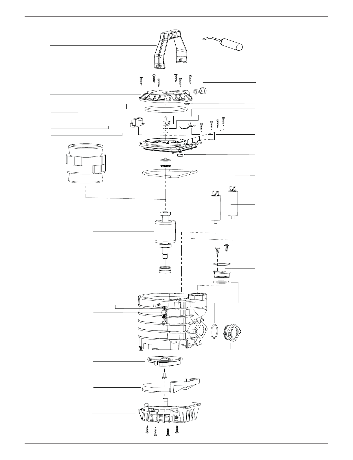
2
1
4
5
3
6
7
8
9
10
11/12/13
14/14.1/14.2
16
15
17
18
19
20
22
21
23
24
25
26
27
28
2
29
32
30/31
34
3
5
33
2
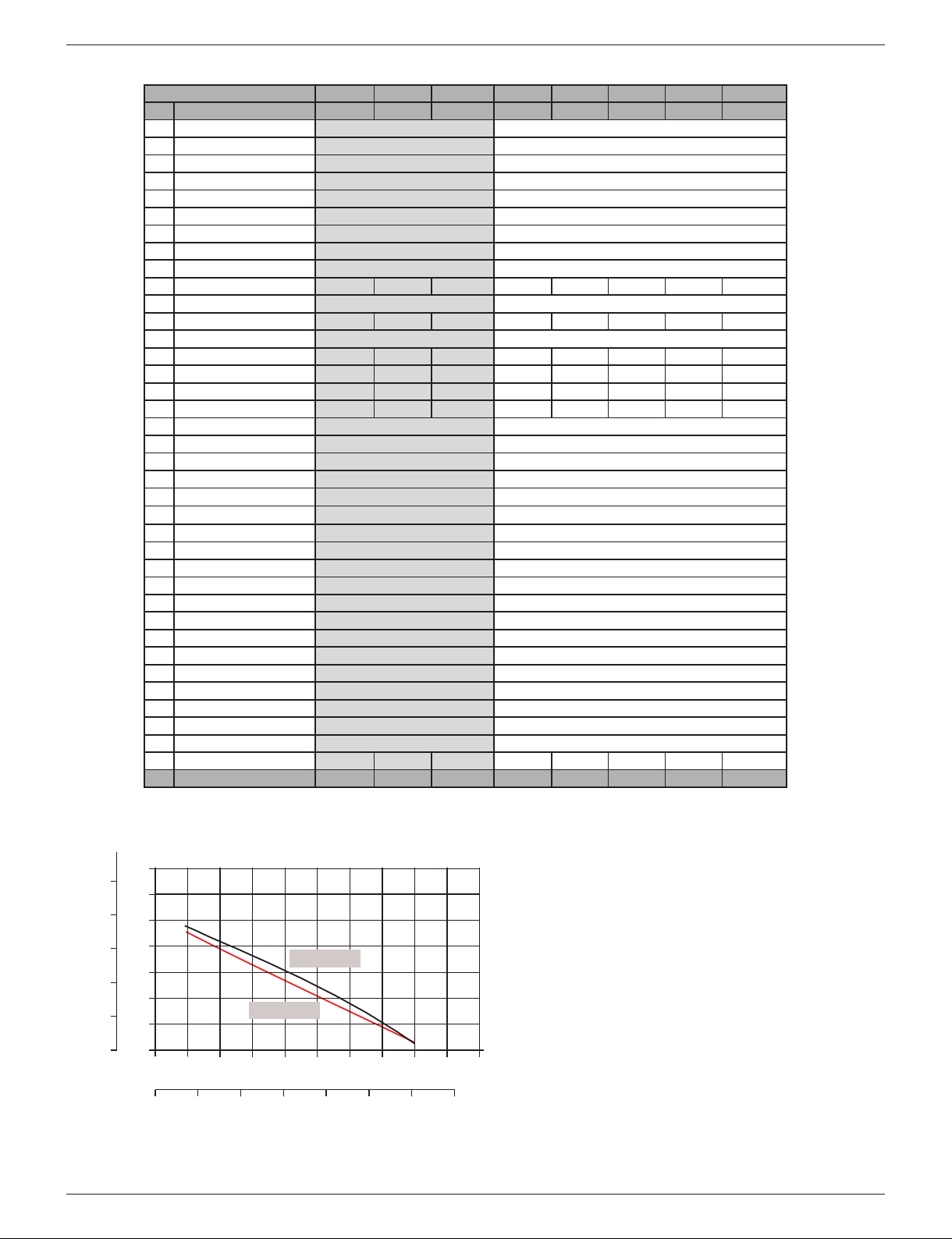
Capacity curve:
35
30
25
20
15
10
5
0
0 5 10 15 20 25 30 35 40 45 50
US GPM
Liters
per second
FEET
METERS
10
8
6
4
2
TOTAL DYNAMIC HEAD
0 25 50 75 100 125 150 175
FLOW RATE
PERFECTA SERIES
®
220 V / 50 Hz
115 V / 60 Hz
Model GF 32-9X IGF 32-9X IGF 32-9XNL GF 32-9 GF 32-9L IGF 32-9 IGF 32-9L TIGF 32-9NL
Pos. Description 201152 201155 201156 201150 201151 20 1153 20 1154 201157
1Pump handle 201787 201787
2Screw 4.2 x 22 201778 201778
3Pump cover 203892 203893
4O-ring 105 x 5 201765 201765
5Screw 201776 201776
6Pump protection relay 204063 --------
7Locking washer 204064 204064
8O-ring 5.6 x 2 201766 201766
9
Pump housing cover 204065 201796
10 Rotor 201762 201795 201795 201762 201762 201795 201795 201745
11 Spacer 201794 201794
12 Shaft seal – Perbunan/FKM 201782 201784 201784 201782 201782 201784 201784 201784
13 Shaft seal – FKM 201784 201784
14 Shaft bolt and serr. washer 017-235 -------- -------- 017-235 017-235 -------- -------- --------
14.1 Shaft bolt -------- 201781 201781 -------- -------- 201781 201781 201751
14.2 Serrated washer -------- 201793 201793 -------- -------- 201793 201793 201793
15 Pull / tension relief 201767 201767 -------- 201767 -------- 201767 -------- --------
16 Screw 2.9 x 13 201780 201780
17 Impeller 204066 201790
18 Pump housing base 201760 201760
19 Suction basket 201757 201757
2
0Outlet cap 201785 201785
21 O-ring 2.5 x 35 201788 201788
22 Threaded outlet 201786 201786
23 Screw 201791 201791
24 Capacitors 204067 201799
25 O-ring 125 x 5 201764 201764
26 Bearing compensating ring 204068 204068
27 Rubber seal 201761 201761
28 Cable connection pin 201783 201783
29 Washer 201775 201775
30 Cable connection pin 201773 20177
31 Serrated washer 201777 201777
32 Pull / tension relief 201768 201768
33 Seal M16 201772 201772
34 Threaded cable grommet 201763 201763
35 Float switch 204069 204069 -------- 201754 -------- 201754 -------- --------
Pos. Description 201152 201155 201156 201150 201151 20 1153 20 1154 201157
Spare parts 220V-pump
Spare parts 115V-pump
NL -> Manual/no float switch
X -> 220V, 50Hz
Technical data
GF 32-9
Pump Material: Noryl GTX 830, 304 S.S Rotor shaft
Seal System: 2 seals (1 FKM, 1 BUNA-N)
Motor Voltage (115 Volt): 115 V, 5.0 Amps, 60 Hz, single-phase std
Motor Voltage (220Volt): 220 V, 2.1 Amps, 50 Hz, single-phase std
Max. Power Consumption: 500 watt
Max. Submersion Depth: 33ʼ (10 m) or limited to length of cable
Overall Dimensions: 7.2ʼʼ (185 mm)
Height Including Handle: 9.8ʼʼ (250 mm)
Weight: 13.5 lbs (6.1kg)
Power Cord (115 Volt): 22ʼ submersible
Power Cord (220 Volt): 16ʼ submersible
Level Regulator: Automatic on/off level control std
Oil filled Motor: Shell Tellus C68 or equal
Thermal Breaker: Capacitor
IGF 32-9
Pump Material: Noryl GTX 830, 316 SS Shaft & Hardware
Seal System: 2 FKM seals
All other components are the same as for GF 32-9. Please see above.
TIGF 32-9
Same as for IGF 32-9 but with all exposed metal parts made of titanium.
and 316 S.S Hardware

ALWAYS DISCONNECT PUMP FROM
LECTRICAL SOURCE BEFORE SERVICING!
E
NOT FOR USE IN FLAMMABLE LIQUIDS!
IMPORTANT:
ACTORY OR YOUR DISTRIBUTOR BEFORE INSTALLATION OR
F
USE.
IN ANY CORROSIVE ENVIRONMENT, CONSULT
cover screws (pos 2) and open top cover. Disconnect wires,
emove motor housing cover (pos 3). Inspect the quality of the oil.
r
If milky or whitish in color, check seals and replace (both seals and
oil) if necessary. To remove rotor, ball bearings and seals, follow
steps described in B. Disassemble pump bottom before
proceeding. Once impeller is off, pull out rotor. Inspect bearings,
replace if necessary. Press out lip seals. Inspect and replace as
necessary.
TROUBLE SHOOTING
ump shuts off:
P
Adjust float switch
Check impeller for free rotation and clogging
Check pump passage, hose or pipe for kink or clog.
Pump is heating up:
Check impeller for free rotation
Check voltage
Pump performance low:
Check for blockage
Check impeller for excessive wear
SERVICE:
Tools needed
Phillips screwdrivers (#1 and #2), locking pliers, 10 mm and 17
mm wrench, ball bearing puller.
A. Disassembly of pump top.
(Check wires, rotor, stator, ball bearings and oil). Remove (pos 39)
handle screws (pos 4). Remove handle. Remove (pos 37) top
B. Disassembly of pump bottom
(strainer, suction cover, impeller) Remove strainer screws (pos
36), remove strainer (pos 6) and suction cover (pos 7). Hold
impeller with vise grip and remove impeller screw (pos 40).
Remove impeller (pos 5). Impeller vanes should have sharp
edges to maximize performance. Replace impeller if vanes are
rounded or dull.
Inspection of pump bottom parts.
Look at lower lip seal parts (pos 27) for visible wear. If damaged
or worn replace both lip seals. To replace lip seals, disassemble
top portion of pump first and remove the oil (see A., disassembly
of pump top).
Note: Both seal openings should face down.
C. Important notes on re-assembly of pump
All O-rings should be lubricated with a silicone based grease, or
lubricated with same oil as in motor, before assembly. Replace
ball bearings to shaft. To re-install inner cover, lubricate bearing
holder. Use a plastic or rubber mallet to lightly tap until cover is in
place. It is important that the bearing is in the absolute center of
the bearing holder when closing the top cover. If not centered, the
shaft will not turn freely.
BJM Pumps, LLC warrants each new pump against defects in workmanship and material for the period of 90 DAYS. It will replace or repair
for the original purchaser, any genuine parts found to be defective upon return to its factory at CT (or other place as designated by it), transportation prepaid by purchaser. The labor involved in replacing defective parts is not warrantable. Other equipment and accessories are warranted only to the extent of the original manufacturerʼs warranty. This warranty does not cover any pump which has been damaged due to careless handling, improper use or application, improper power supply, use in unsuitable liquids, or faulty installa tion. Alteration or repair by other
than BJM Pumps, LLC (or designated service facility) voids this warranty.
BJM Pumps, LLC assumes no liability for damages, losses, inconveniences, direct, or consequential, any kind in respect to the use or operation of the pumps or any equipment or accessory used in connection herewith.
This warranty encompasses the entire understanding between the purchaser and BJM Pumps, LLC and no other person is authorized to extend or alter the terms of the warranty. This warranty is effective only when the warranty certificate card is properly completed and returned
to BJM Pumps, LLC at the time of purchase.
BJM Pumps, LLC
KEEP FOR YOUR RECORDS
Date Purchased:_________________________________________________________________
Model: _____________________Serial No.: __________________________________________
Dealer Name: ___________________________________________________________________
BJM PUMPS, LLC
123 Spencer Plain Rd., P. O. BOX 1138
Old Saybrook, CT 06475
TEL. (860) 399-5937, FAX (860) 399-7784
http://www.bjmpumps.com
Perfecta Pump is a registered trademark of BJM Pumps, LLC
Order-Nr. 099-156 07/2013
 Loading...