


mOway
MOWAY’S
BEGINNER MANUAL

MOWAY
Title: mOway Beginner Manual
Rev: v2.1.3 – March 2011
Page 2 of 65
www.moway-robot.com
Copyright (c) 2010 Bizintek Innova, S.L.
Permission is granted to copy, distribute and/or modify this document under the
terms of the GNU Free Documentation License, Version 2.0 or any later version
published by the Free Software Foundation; with no Invariant Sections, no Front-Cover
Texts, and no Back-Cover Texts. A copy of the license is included in the section
entitled "GNU Free Documentation License".

MOWAY
Title: mOway Beginner Manual
Rev: v2.1.3 – March 2011
Page 3 of 65
www.moway-robot.com
Index
Index ................................................................................................................................. 3
1.Prologue .................................................................................................................... 5
2.What is mOway? ...................................................................................................... 7
3.Robot mOway ........................................................................................................... 8
3.1.Processor ............................................................................................................ 8
3.2.Drive system ...................................................................................................... 9
3.3.Sensor and indicators group ............................................................................. 10
3.3.1.Line sensors .................................................................................................. 11
3.3.2.Obstacle detection sensors ........................................................................... 13
3.3.3.Light sensor .................................................................................................. 14
3.3.4.Expansion connector .................................................................................... 14
3.3.5.Temperature sensor ...................................................................................... 15
3.3.6.Speaker ......................................................................................................... 15
3.3.7.Microphone .................................................................................................. 15
3.3.8.Accelerometer .............................................................................................. 16
3.3.9.Battery level ................................................................................................. 16
3.3.10.Front LED ................................................................................................. 16
3.3.11.Top two-color LED .................................................................................. 16
3.3.12.Brake LED ................................................................................................ 17
3.3.13.Free Pad .................................................................................................... 17
3.4.Power Supply System ...................................................................................... 17
3.5.RF module and RFUsb .................................................................................... 18
3.6.Camera module and Moway Videocap ............................................................ 20
4.First Steps ............................................................................................................... 21
4.1.mOway Pack installation ................................................................................. 21
4.2.Download a program to mOway ...................................................................... 22
4.3.RFUsb instalation ............................................................................................ 22
4.4.RF modules ...................................................................................................... 23
4.5Moway Videocap drivers installation .............................................................. 24
5.mOwayGUI programming ...................................................................................... 25
5.1.Creating a Project ............................................................................................. 25
5.2.First programme in mOwayGUI ...................................................................... 25
5.3.mOwayGUI ...................................................................................................... 32
5.3.1.Modules ........................................................................................................ 32
5.3.2.Conditionals ................................................................................................. 44
5.3.3.Start and End ................................................................................................ 56
5.3.4.Arrow ........................................................................................................... 56
5.3.5.Erase Arrow.................................................................................................. 57
5.3.6.Subroutines ................................................................................................... 57
5.3.7.Recording ..................................................................................................... 57
6.Moway RC Center .................................................................................................. 58
6.1.Description of the mOway RC Center ............................................................. 59
6.1.1.RF configuration .......................................................................................... 59

MOWAY
Title: mOway Beginner Manual
Rev: v2.1.3 – March 2011
Page 4 of 65
www.moway-robot.com
6.1.2.Radio control ................................................................................................ 60
6.1.3.LED .............................................................................................................. 60
6.1.4.Speaker ......................................................................................................... 60
6.1.5.Info ............................................................................................................... 60
6.1.6.Sensor status ................................................................................................. 60
6.1.7.Keyboard control .......................................................................................... 60
7.MowayCam ............................................................................................................ 61
8.Moway RC CAM Center ........................................................................................ 62
MOWAY
Title: mOway Beginner Manual
Rev: v2.1.3 – March 2011
Page 5 of 65
www.moway-robot.com
1. Prologue
The dawning of a new era; the era of the minirobots. Increasingly more mobile
robotics applications enter our daily life. We can currently find robots which help us
with simple tasks like cleaning household floors, mowing the lawn or keeping the
swimming pool clean. As technology keeps improving, these small devices which blend
mechanics, electronics and software are performing more and more complex tasks*.
They are slowly introducing themselves into our lives in a useful manner and reducing
the burden of unpleasant jobs.
It’s not too far-fetched to think that the revolution which took place in the IT or
telecommunications fields will be repeated with robotics in the next decade. Enough
technology is currently available to manufacture these devices and society is also ready
to receive them in the market. Yet, a specific catalyst is needed to start this revolution.
People also need to be ready and prepared to identify in what fields microrobotics may
have an opportunity and which new applications may be interesting to implement.
Up till now processors weren’t able to move. But today things have changed.
Software is one of the fundamental elements in the world of mobile robotics. The main
difference between developing a program for these robots and running it with a personal
computer is interaction with the environment. The environment isn’t changing randomly
in PC applications, so decision making and programming are simplified. On the other
hand, when running commands for a minirobot application usually the result is
unknown, therefore algorithms have to consider situations with a wider range of
possibilities, some of them unexpected.
The mOway robots are tools specifically designed for teaching and research. Their
purpose is to bring the world of autonomous robots closer to the teaching centers.
mOway’s main purpose is to be a useful tool for those who are being introduced
for the first time to the world of the minirobots as well as for those who are already
experienced and wish to perform complex collaborative robotic applications.
mOway aims to stimulate enthusiasm for this new and exciting branch of
engineering in a prompt and enjoyable way through the practical exercises included in
this manual.
- An easy and entertaining way to learn.
- This book’s purpose: to be mOway’s Manual and not a comprehensive book on
minirobotics.
This manual has been implemented to assist learning how to use mOway. It
provides some basic notions on using mOway and its functions in a quick and clear
manner.

MOWAY
Title: mOway Beginner Manual
Rev: v2.1.3 – March 2011
Page 6 of 65
www.moway-robot.com
This manual is divided in two parts. The first part includes a description of the
elements which form part of the robot and their functioning. The second part of the
manual includes a series of practical exercises that can be executed with mOway.

MOWAY
Title: mOway Beginner Manual
Rev: v2.1.3 – March 2011
Page 7 of 65
www.moway-robot.com
2. What is mOway?
mOway is an autonomous programmable small robot designed mainly to perform
practical minirobotics applications.
It provides a perfect hardware platform for those wishing to take their first steps
within the world of mobile robots as well as for those who have already worked with
minirobots and want to develop more complex applications.
The mOway robot is equipped with a series of sensors which aid it to move in a
real environment. It also includes a drive unit which allows it to move over smooth
terrain commanded by a I2C communications bus. All these peripherals are connected
to a microcontroller responsible for governing the robot.
This small robot incorporates I2C/SPI expansion bus options. As an example, a
wireless communications module, a video camera or a prototype card can be connected
to it as well as any other device considered interesting to perform a certain task.
mOway’s external design is very compact, intended to move with grace and style
avoiding standstills due to obstacles or corners. This small mobile device has been
fittingly called a “pocket robot”.
mOway is a perfect tool for those who want to both learn and teach minirobotics.
The user will be pleasantly surprised by the speed in achieving results even if this is the
first time he/she comes into contact with mobile robots.
MOWAY
Title: mOway Beginner Manual
Rev: v2.1.3 – March 2011
Page 8 of 65
www.moway-robot.com
3. Robot mOway
This chapter describes each of the parts that constitute the mOway. It is important
to highlight that it is not necessary to know the total functioning of the robot to be able
to program it, at least not at the level of detail explained here.
The following elements are to be found inside mOway:
• Processor
• Drive system
• Sensors and indicators group
• Power supply system
• An expansion connector
3,&IM
)521
7B/('
,
5
B
5
;
B
5
/,1(B7;
/,1(B5;B5
/,*+7B
6(1
(
;
3
$
1
6
,
2
1
,
5
B
5
;
B
/
/,1(B5;B/
/('B
*5((1
/('B
5('
3,&)
/,1(B7;/,1(B5;B5
/,1(B7;/,1(B5;B5
+%ULGJH
(
1
*
,
1
(
(
1
*
,
1
(
*HDU
(QFRGHU
*HDU
(QFRGHU
,
5
B
5
;
B
5
,
5
B
5
;
B
/
/('B
%5$.(
/('B
%5$.(
$&&(/(
63($.(5
0,&
7(03
%$77(5<
0(7(5
)5((
3$'
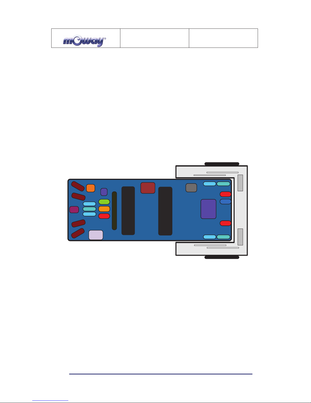
Image 1. Diagram of mOway’s parts
3.1. Processor
mOways are governed by a 4 Mhz PIC18F87J50 microcontroller manufactured by
Microchip Technologies. All the peripherals distributed throughout the whole robot are
connected to its input/output ports. Some of them need a digital input or output, others
need an analog input or output and others, instead, are controlled by one of the I2C/SPI
communication buses. The table below describes how the microcontroller pins are
distributed.
MOWAY
Title: mOway Beginner Manual
Rev: v2.1.3 – March 2011
Page 9 of 65
www.moway-robot.com
3.2. Drive system
To be able to move the mOway uses a double servo-motor group. It includes both
an electronic part and a mechanical one. The electronic part is mainly in charge of
controlling the motor’s speed and the mechanical part allow the mOway to move
unhindered over different terrains with adequate power.
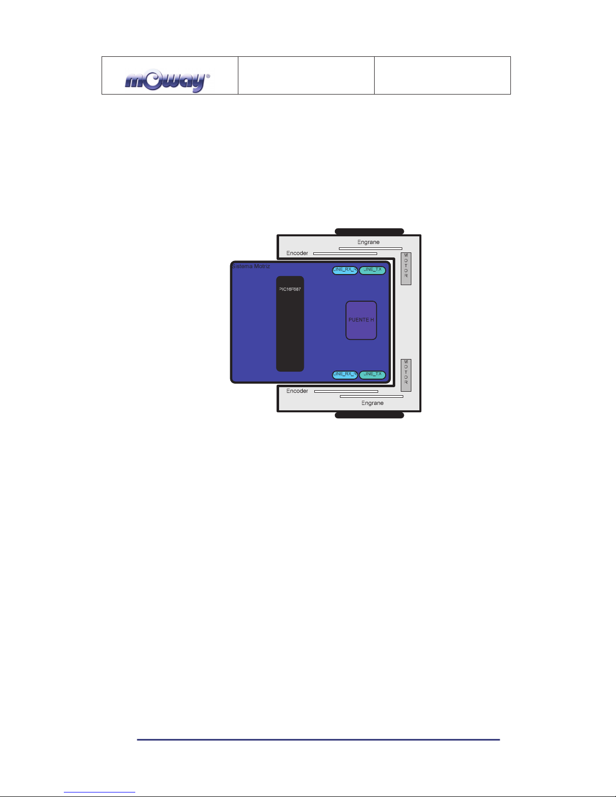
Image 2. Drive system: electronic and mechanical
The servo-motor group includes different features:
1. Speed control: controls the speed of each motor.
2. Time control: controls the time for each command with a 100 ms precision.
3. Traveled distance control: Controls the distance traveled by each command
with a precision of 1 mm aprox.
4. General speedometer: counts distances traveled since the initial command.
5. Angle control: controls the angle when the mOway rotates.
The microcontroller sends the I2C command to the drive system that controls the
motors and therefore releasing the main microcontroller so it can carry out other tasks.
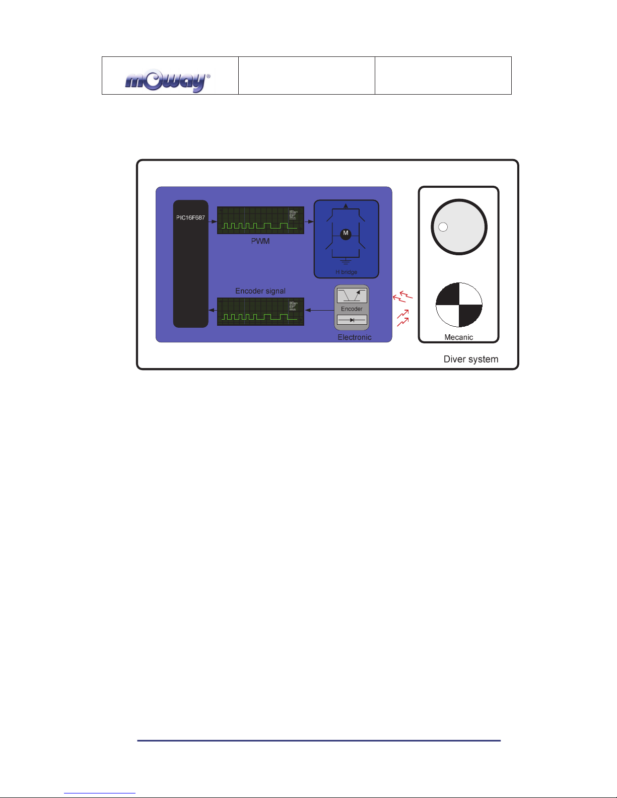
Speed control is carried out by means of proportional control with negative
feedback from the encoders’ signal. The illustration displays the controlling system. The
microcontroller feeds the motors through an H bridge controlled by pulse width
modulation (PWM) signals. Wheel rotation is monitored by an encoding sticker and an
infrared sensor. When the sticker shows its black segment, the logical output shall be 1
and when it shows the white sector the output shall be 0. The microcontroller analyzes
these signals (it can determine the exact wheel speed by measuring the pulse width) and
MOWAY
Title: mOway Beginner Manual
Rev: v2.1.3 – March 2011
Page 10 of 65
www.moway-robot.com
acts on the motors. This way, the mOway will be able to keep the speed constant on any
surface.
Image 3. Motor control
To send a movement command to the robot, via the main microcontroller, all we
need to do is send the movement command parameters. To this end some libraries were
designed in assembly and C language to simplify communications through some
functions which are responsible for I2C communications. The format for these frames is
explained in the motors and drive system library section.
The table below describes connections between the main PCB and the servomotor unit.
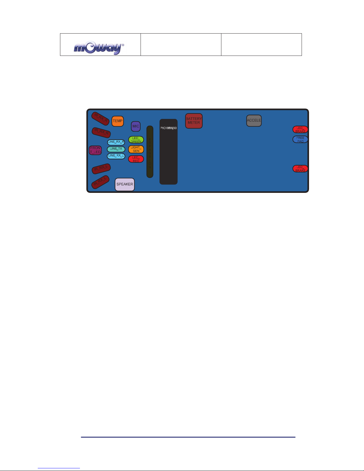
3.3. Sensor and indicators group
This group consists of different luminous sensors and indicators, connected to the
mOway microprocessor, through which the robot interacts with the external world:
• Two line tracking sensors.
• Four obstacle detection sensors.
• A light sensor.
• An expansion connector.
• Four LED diodes.
• Temperature sensor.
• Speaker.
• Microphone.
MOWAY
Title: mOway Beginner Manual
Rev: v2.1.3 – March 2011
Page 11 of 65
www.moway-robot.com
• Accelerometer.
• Battery level.
Image 4. Sensors and indicators group
3.3.1. Line sensors
The line tracking sensors are two reflection optocouplers mounted on the top front
part of the robot. They use infrared light reflection to detect the color of the terrain at
the point where the robot is.
These two sensors are connected to two microcontroller analog ports so strong
terrain contrasts, like white lines on black backgrounds, can be detected. They are also
capable of distinguishing different tones.
The Vishay CNY70 sensor has a compact construction where the emitting light
source and the detector are arranged in the same direction to be able to detect by using
the reflective IR beam the light reflected in the terrain.
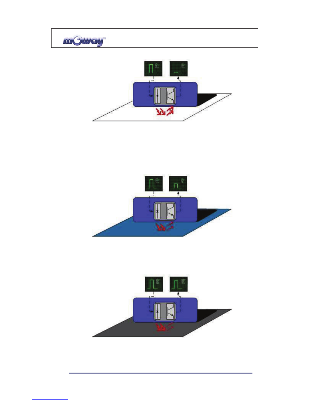
In the images below the three possible cases can be observed:
1. Clear surface: A white surface reflects all the infrared light and
therefore we obtain a low voltage reading at the transistor’s output when
in regular mode.
MOWAY
Title: mOway Beginner Manual
Rev: v2.1.3 – March 2011
Page 12 of 65
www.moway-robot.com
Image 5. Line tracking sensor on a clear surface.
• Colored surface: A colored surface reflects part of the emitted light
obtaining an intermediate voltage at the microcontroller’s analog
channel input. This way colors are easily identified
1
.
Image 6. Line tracking sensor on a colored surface.
1. Dark surface: A dark surface reflects very little light obtaining a high
voltage reading at the sensor’s output.
Image 7. Line tracking sensor on a dark surface.
1
Due to CNY70 tolerance two different sensor can differ.
MOWAY
Title: mOway Beginner Manual
Rev: v2.1.3 – March 2011
Page 13 of 65
www.moway-robot.com
Image 8. Location of line sensors
3.3.2. Obstacle detection sensors
Similar to line tracking sensors, obstacle detection sensors also use infrared light
to detect objects located in front of the mOway. The sensor includes two infrared lightemitting source (Kingbright KPA3010-F3C) and four receivers placed on both sides of
mOway.
The output of the Sharp PT100F0MP receivers are connected to the
microcontroller’s analog inputs so it can detect the presence of any object (digital mode)
and also measure how far away it is (analog mode)2.
The sensor functions similarly to the line tracking sensor. The light emitter
generates a 70us pulse which allows the receiver to capture any obstacle using a
filtering and amplifying stage. Once the signal is processed electronically, the PIC can
measure it by means of the ADC or as a digital input. The digital distance range is close
to 3cm and a bright environment is recommended to enhance infrared light reflection.
Image 9. Obstacle detection sensor
2
Due to tolerance two different sensors can differ from each other.
MOWAY
Title: mOway Beginner Manual
Rev: v2.1.3 – March 2011
Page 14 of 65
www.moway-robot.com
Image 10. Location of Obstacle Sensor
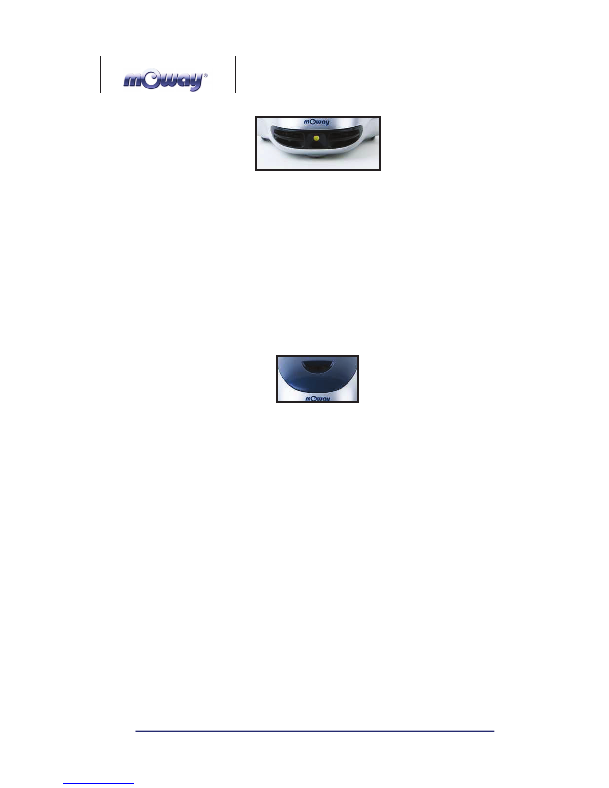
3.3.3. Light sensor
This sensor allows mOway to recognize the light intensity that enters through a
small half moon-shaped opening on the top part of the chassis. Since it is facing forward
it enables it to detect where the light source is located and to act accordingly.
The output of the AVAGO APDS-9002 sensor is connected to the analog port of
the microcontroller so that with a simple reading of the ADC we can register the light
intensity level and any change in intensity levels based on the last reading
3
.
Image 11. Location of Light Sensor
3.3.4. Expansion connector
This connector allows the mOway to connect with any commercial modules or
electronic circuits the user may choose.
As shown in the above table, it is possible to connect commercial SPI devices. On
the other hand, the RF BZI-RF2GH4 module available in the market is totally
compatible with mOway and with specific libraries. This module enables the mOway to
communicate with other robots and with a PC via the RFUsb. With this module it is
possible to create complex collaboration applications without having to worry about
complicated wireless communications.
3
Top two-color LED has to be switched off to have a valid measure.
MOWAY
Title: mOway Beginner Manual
Rev: v2.1.3 – March 2011
Page 15 of 65
www.moway-robot.com
Image 12. RF modules into expansion connector.
3.3.5. Temperature sensor
mOway has installed as a temperature measurer an NTC thermistor from Murata,
a semiconductor whose electrical variable resistance decreases as temperature increases.
The sensor is located in the front part of the robot, very close to obstacle sensor.
The thermistor is connected to the analog port of the microcontroller so that with a
simple reading of the ADC it is possible to get the temperature value in that moment
and notice any change in it since the last reading
4
.
3.3.6. Speaker
The CMT-1102 speaker from CUI INC directly connected to the microcontroller,
is capable to play tones from 250 Hz to 65 KHz.
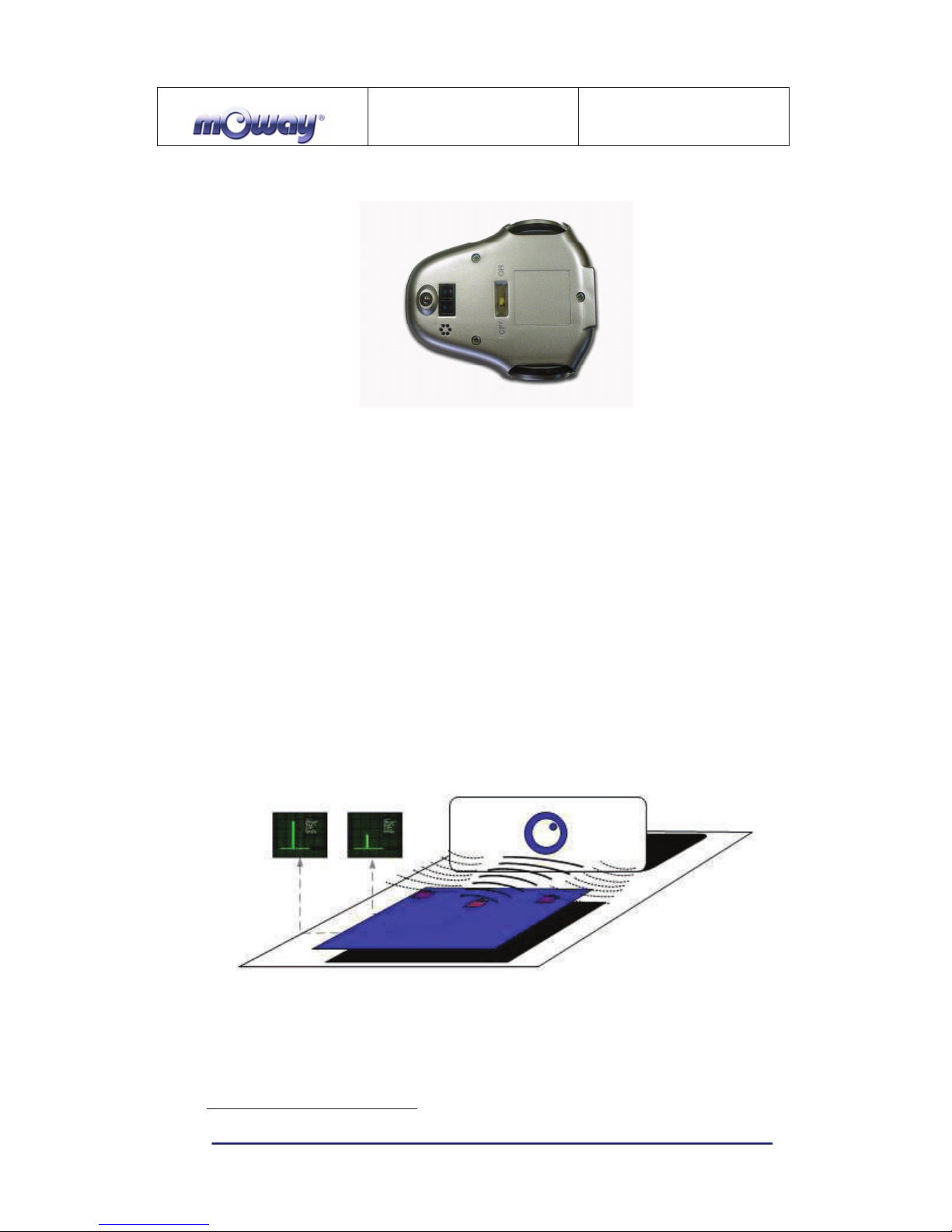
3.3.7. Microphone
The CMC-5042PF-AC microphone from CUI INC enables the robot to detect
sounds from 100 Hz to 20 KHz.
The output is directly connect to an analog input of the microcontroller so that it is
capable to detect not only if there is sound or not (digital mode) but also the intensity of
the sound with a simple reading of the ADC (analog mode).
4
Temperature measured by the sensor can be 5ºC higher than external temperature.

MOWAY
Title: mOway Beginner Manual
Rev: v2.1.3 – March 2011
Page 16 of 65
www.moway-robot.com
3.3.8. Accelerometer
An accelerometer is a device that measures acceleration and the gravity induced
forces: the movement and rotation. There are many types of accelerometers, most of
them based on piezoelectric crystals, but their size is too big. Because of that, it was
tried to design a small device in the field of microelectronics, which might improve the
applicability. Then, the MEMS (Microelectromechanical Systems) accelerometers were
created.
An easy way to create an accelerometer is measuring changes in a capacitor.
Capacitors can work as sensors or as actuators. In the case of mOway, it is a capacitive
accelerometer, which consists of two capacitors displaced in differential mode whose
electrical capacity changes as the acceleration varies.
By measuring X, Y, Z axes of the MMA7455L accelerometer from
FREESCALE Semiconductor, it is possible to know if mOway is correctly positioned,
inverted or tilted.
3.3.9. Battery level
The robot has a LiPo cell battery rechargeable. For proper operation of the
microcontroller, the battery is connected to one of its analog inputs through a splitter.
Thus, with a reading of the ADC battery level can be measured.
3.3.10. Front LED
The front LED is a white LED placed on the front side of mOway. The output of
the OSRAM LW A6SG LED is connected to a digital output of the microcontroller.
3.3.11. Top two-color LED
This double indicator and the light sensor share the same opening on the top part
of the robot. They are connected to two microcontroller digital outputs
5
.
5
Please note that since they share the same opening as the light sensor it is fundamental to switch
them off when wanting to perform a light intensity reading.
MOWAY
Title: mOway Beginner Manual
Rev: v2.1.3 – March 2011
Page 17 of 65
www.moway-robot.com
Image 13. Robot with Front LED and red LED switched on
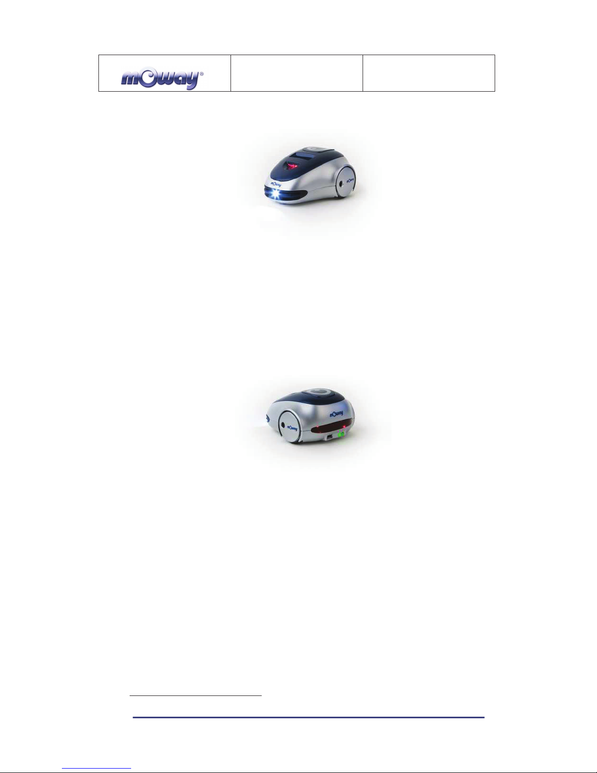
3.3.12. Brake LED
The brake LED is double indicator placed on the back side of mOway. The output
is connected to one digital outputs of the microcontroller.
Image 14. Brake LED location. Switch on green LED.
3.3.13. Free Pad
mOway has implemented a free Pad to allow expert users to connect their
electronics. It is accessible opening the robot and it´s located near brake LED
6
.
3.4. Power Supply System
mOway’s battery is located inside and accessible only by disassembling the
product. It is a small rechargeable LiPo cell.
The battery can be charged via a computer’s USB port through the mOway’s
MINI-USB-B port. There is no need to wait for the battery to be completely discharged,
as it can be plugged in any time since these batteries do not have memory effect (also
6
Advanced users only
MOWAY
Title: mOway Beginner Manual
Rev: v2.1.3 – March 2011
Page 18 of 65
www.moway-robot.com
known as lazy battery effect). These batteries are a perfect power source for mOway
due to their small size, lightness and flexibility.
Battery duration depends to a great extent on the active sensors and the amount of
time the motors are used. Charging lasts about 2h.
Power supply system controls two LED located in the back part of the robot
7
.
Green LED indicates that mOway is switched on and red LED indicates that the battery
is charging. When the battery is full red LED will switch off
8
.
Image 15. Charging (red) and switched on (green)
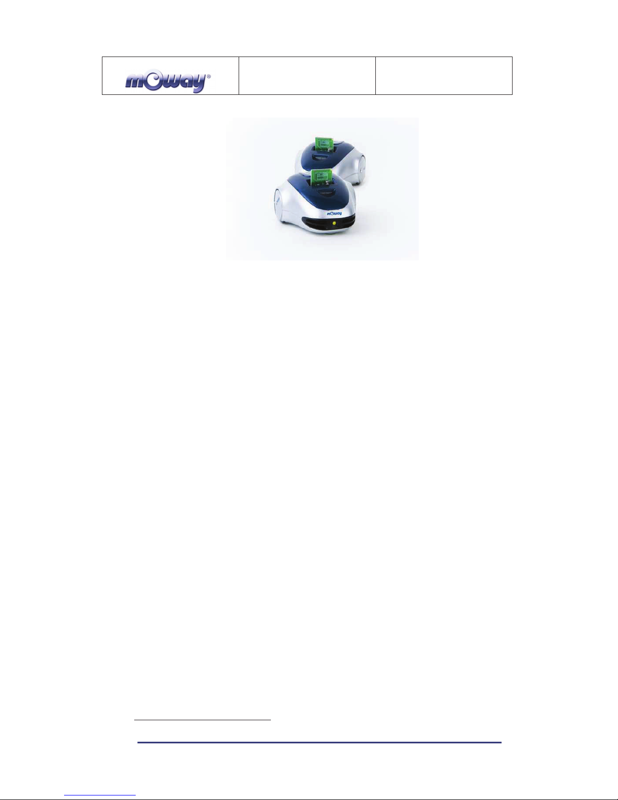
3.5. RF module and RFUsb
9
RF module allows communicate with other mOways or with PC using RFUsb.10.
Image 16. RF module
7
These LEDs can´t be controlled by the user.
8
This LED can swap between on and off when the battery is fully charge because there is energy
consumption when mOway is plugged.
9
Available in some packs
10
Available in some packs
MOWAY
Title: mOway Beginner Manual
Rev: v2.1.3 – March 2011
Page 19 of 65
www.moway-robot.com
RF module is connected in expansion connector and it is very easy to use with
mOwayGUI. The best way to start working with the module is using an example project
provided in mOwayPack.
Image 17. RFUsb
The BZI-RF2GH4 radio-frequency communications module is based on the
nRF24L01 transceptor manufactured by “Nordic Semiconductors”. This integrated
circuit has been fitted with all the logic required to establish wireless bidirectional
communications with acknowledgement of receipt. Communications with the
microcontroller is made via an SPI bus.
The main characteristics of the BZI-RF2GH4 module are as follows:
• Low consumption.
• Working frequency: 2.4GHz,
• Transmitting power between-18 and 0 dBm,
• Transmission speed between 1 and 2 Mbps,
• 128 in transmission channels selectable by the SPI bus.
In addition to the CI nRF24L01, the BZI-RF2GH4 is also fitted with all the
associated electronics for its correct operation plus a microstrip antenna on the same
board with the impedance adaptation network. In this way the user can forget
completely about the hardware required to implement the radio part of his application.
As interface, the device has four pins available for the SPI bus, two more pins for
controlling the module and another two for the supply.
In order to facilitate the handling of the module, a number of libraries have been
developed to simplify and shorten the development time of wireless applications with
these modules.
MOWAY
Title: mOway Beginner Manual
Rev: v2.1.3 – March 2011
Page 20 of 65
www.moway-robot.com
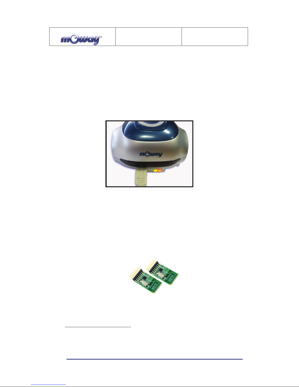
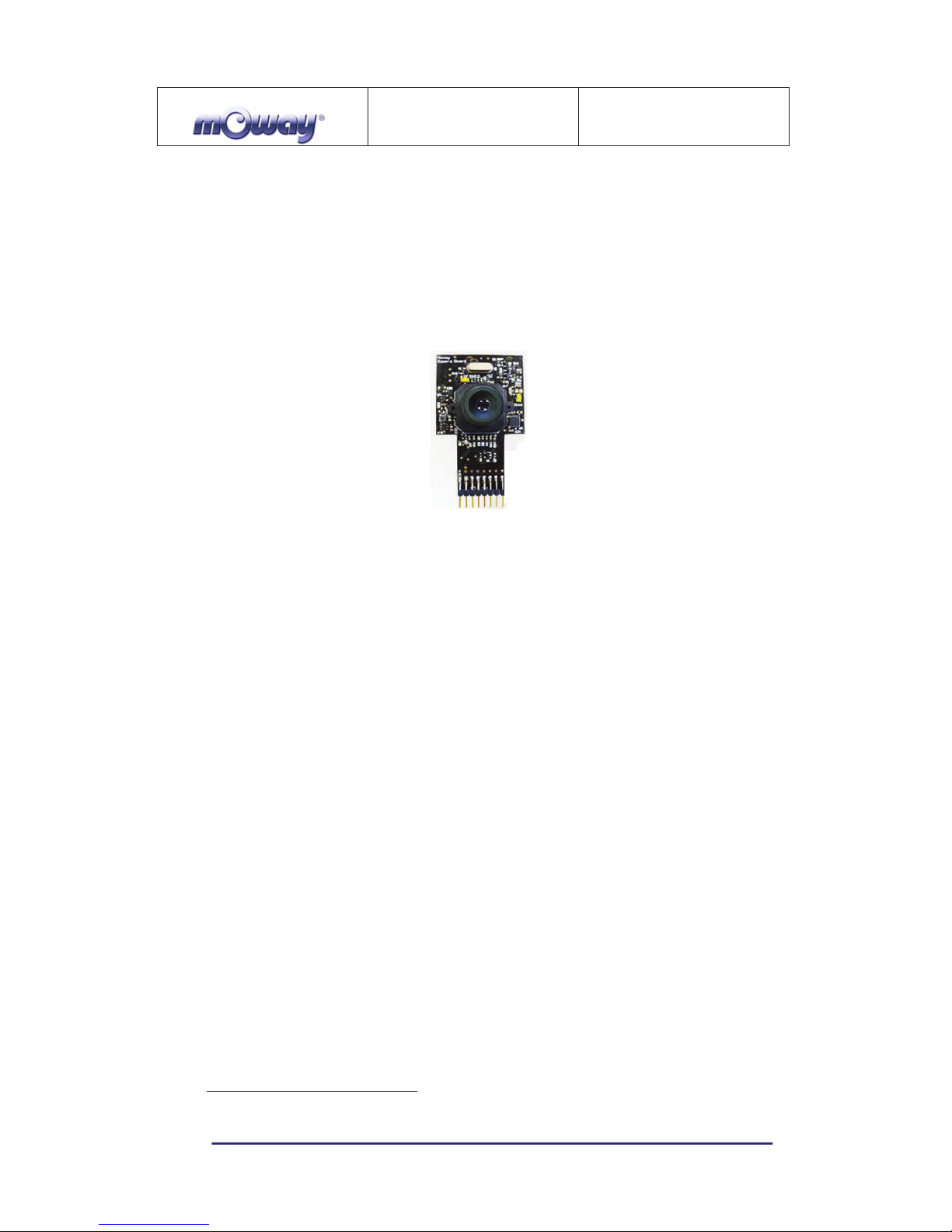
3.6. Camera module and Moway Videocap
Thanks to the camera module (Moway Camera Board11) it is possible to display
on the computer what Moway is “watching” . Camera board sends images wirelessly to
the video Moway Videocap
12
.
Image 18. Camera module Moway Camera Board
Camera module is connected in expansion connector and it is very easy to use
with mOwayGUI. Video Moway Videocap must be connected to an USB connector of
the computer.
Camera control is performed by Microchip MCP23S08 device, which is an
input/output port managed by SPI. A library is provided to make easier for user to
develop programs with the camera module. The basic functions are the camera ON and
OFF, and the selection of the transmission channel from de camera to the video Moway
Videocap. User have to select the same channel (from 1 to 4) both in program and
Moway Videocap. The status of the camera is shown by a LED on camera board.
As interface, the device has four pins available for the SPI bus, two more pins for
controlling the module and another two for the supply.
NOTE: Both camera transmission and RF module transmission are in the same
frequency band. So that, when camera is active, RF module reception distance
decreases.
11
Available in some packs
12
Available in some packs
 Loading...