

Troubleshooting Guide
Best Practices
bizhub 8 Series
201802

Table of Contents
The Initial Operation During MFP Start-up ..................................................................................................... 2
bizhub C258/C308/C36 8/ C458/C558/C658/ 308/ 36 8/ 458/ 558 Troubleshooting Guide .............................. 6
Boot-Up Issue ................................................................................................................................................ 6
Error Code Issue ........................................................................................................................................... 7
Firmware Issue .............................................................................................................................................. 8
C-DFA0 (ASIC image access failure) .......................................................................................................... 11
Paper full message on the exit tray 1 ........................................................................................................... 12
The speaker volume was difficult to hear ..................................................................................................... 14
Fusing offset image ..................................................................................................................................... 14
Frequent jam code J20-01, J20-02 (misfeed, vertical transport section) ..................................................... 16
Notice of setting the FK-513/514/515 .......................................................................................................... 17
Installation of the FK-514 is difficult ............................................................................................................. 18
No Fax Reception ........................................................................................................................................ 19
Handling instruction for SC-508 ................................................................................................................... 20
How to Safely Rem ov e an EEPR OM ........................................................................................................... 21
Self-Diagnostic Function (KBA01400523) ................................................................................................... 23
C9401 Refresh-Models ONLY (KBA00034462) ........................................................................................... 26
How to Obtain Log Files from the MFP (KBA00032414) ............................................................................. 27
How do I confirm that the content in a Log gathered is correct? (KBA00035540)........................................ 40
MFP Log Acquisition Tool ............................................................................................................................ 46
How can I check if my software switches are set to factory settings? (KBA00035539) ............................... 47
1

No.
Boot up
Process
PWB
Boards
Operation Panel
Status of LEDs
Operation Panel
Malfunction/ Probable
Cause
Corrective Action
Boot Diagnosis
(Turn Main SW on while
pushing power key)
1
The Initial Opera tion during MFP Start up
Turn ON Main
Power SW
2
Startup Boot
program on
SPI Flash
MFPB
(SPI-Flash)
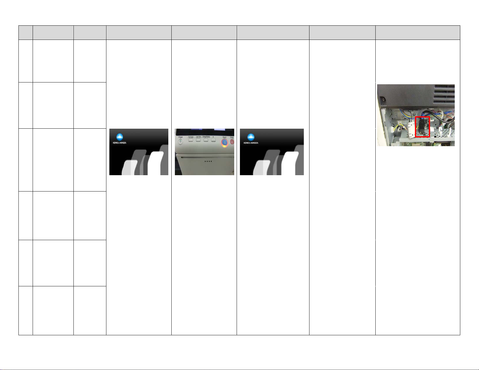
Black Screen
No LED’s are turned on.
Black Screen
Remains Black screen
[Probable Cause]
Power is NOT supplied
Contact failure of Option
DIMM
MFPB Failure
Op Panel contact failure
1. Check the power supply
2. When the Option DIMM is
installed, disconnect it and check if
the machine boots up.
3. Check the connector between
MFPB- Operation Panel
4. Replace the MFPB
5. Replace the Op Panel cable
6. Replace the Op panel unit
3
<START>
Initialize DIMM,
RTC, TPM
MFPB
(CPU->
DIMM, RTC,
TPM)
2

No.
Boot up
Process
PWB
Boards
Operation Panel
Status of LEDs
Operation Panel
Malfunction/ Probable
Cause
Corrective Action
4
5
Contact failure of Option
Contact failure of eMMC
2. Reinstall eMMC board
4. Replace the MFPB
6 <START>
MFPB
7
into DIMM
board)
8
board)
board)
MFPB
[Probable Cause]
<START>
Screen does not switch to
When option DIMM is installed,
<END>
Initialize
DIMM, RTC,
TPM
Check option
DIMM
Download
Boot program
into DIMM
<END>
download
Boot program
<START>
Download FW
from eMMC
into DIMM
MFPB
(CPU -->
DIMM,
RTC, TPM)
MFPB< -- >
Option
DIMM
(SPI-Flash> DIMM on
board)
MFPB
(SPI-Flash> DIMM on
eMMC -->
MFPB
(eMMC -->
DIMM on
Two Bars
LED of Start Key turns
Orange and LED of Power
Key turns as follows.
Installed: Purple
Not Installed: Orange
Two Bars
LED of Power Key: ON
Data Indicator lamp: OFF
[Probable Cause]
DIMM
SPI-Flash or DIMM on
MFPB
1. When option DIMM is installed,
disconnect it and check if the
machine boots up.
If the machine boots up, reinstall
Option DIMM or replace one.
3. Download the FW
5. Replace the eMMC board.
9
<END>
download FW
from eMMC
into DIMM
10 Startup FW
on DIMM
11
FW
Initialization
eMMC -->
MFPB
(eMMC -->
DIMM on
(DIMM on
board)
MFPB
Data indicator lamp turns
ON.
4 Bars
4 Bars
Data indicator lamp turns
ON, but the screen does
not switch to “4 bars”
screen.
DIMM on MFPB failure
Boot up screen.
[Probable Cause]
MFPB failure
1. Download the FW.
2. Replace the MFPB.
disconnect it and check if the MFP
boots up.
If the MFP boots up, reinstall the
option DIMM again or replace it.
3
No.
Boot up
Process
PWB
Boards
Operation Panel
Status of LEDs
Operation Panel
Malfunction/ Probable
Cause
Corrective Action
(Boot up screen)
Indicator lamp turn OFF
(Boot up screen)
[Probable Cause]
then disconnect & connect it.
12
<END>
FW
Initialization
13
<START>
Initial
communication
to HDD
14
<START>
Initial
communication
to ENG
(Printer)
MFPB
MFPB<- ->
HDD
MFPB <-->
MFPB
KM’s Logo and 5 Bars
LED of Power Key & Data
KM’s Logo and 5 Bars
Remain Boot up screen
Connection with CCD
board failure
MFPB failure
HDD failure
1. Check the connector between
CCD board - MFPB for proper
connection.
2. Check the connector on MFPB
from CCD board.
3. Check the HDD SATA cable,
15
<START>
Initial
communication
to CCD Board
16
<END>
Initial
communication
to ENG
(Printer)
17
<END>
Initial
communication
to CCD Board
MFPB < -- >
CCD Board
MFPB < -- >
MFPB
MFPB < -- >
CCD Board
4. Download the FW
5. Replace the MFPB
4

No.
Boot up
Process
PWB Boards
Operation Panel
Status of LEDs
Operation Panel
Malfunction/ Probable
Cause
Corrective Action
C-D271
C-6901
18
<END>
Initial
communication
to HDD
<START>
19
Initial
communication
to FAX board
MFPB < -- >
HDD
MFPB < -- >
FAX board
LED of Start Key turns
Blue.
The Self diagnostic screen is
displayed after Boot
diagnosis.
Trouble Code is displayed.
[Probable Cause]
C-FA14 or C-D**
Connection failure of HDD
HDD failure
C-B003
Connection failure of
FAX board
FAX board failure
C-6753
Connection failure of
DSIPB
DSIPB failure
Refer to the Service manual for
corrective actions to each Trouble
Code.
<END>
20
Initial
communication
to FAX board
<START>
21
Initial Network
settings
<END>
22
Initial Network
settings
MFPB < -- >
FAX board
Connection failure of
Option DIMM
Option DIMM failure
MFPB
Connection failure of
DSC board
DSC board failure
MFPB
5

bizhub C258/C308/C368/C458/C558/C658 Troubleshooting Guide
This troubleshooting guide has been developed to assist field service representatives. The goal is to reduce down time,
avoid multiple service calls, avoid unnecessary parts replacement, and increase dependability. Common steps will be
covered if the MFP experiences operational issues in the following areas:
• Boot Up Issue
• Error Code Issue
• Firmware
BOOT UP ISSUE
1. If the 8 series MFP is LOCKED during the boot sequence, follow the steps below.
A. Power off the main switch, wait 10 seconds, power the MFP back on while holding down the sub power
switch on the op-panel. Wait for a “beep” and then release the sub power switch. The op-panel should
display the Self Diagnostics mode. Press the start button when it turns blue. Once the diagnos ti cs has
completed, look for any “NG” results.
When the machine is stuck at any pillar during boot up, always remove all accessories from the main body.
(DF, Finisher, and any optional paper trays)
2. Understanding the “phases or timing of the boot process
• Specific boot-up processes tak e plac e at eac h pil l ar .
o First Pillar
Machine starts boot cycle and verifies the firmware file.
o Second Pillar
Machine memory check (standard onboard memory, DIMM, ASIC777, ASIC30EFI,
ASIC777 DS board)
Scanner moves and initializes, energizes scan lights
o Third Pillar
Accesses EMMCB board
o Fifth Pillar
Scanner homes and exposure lamp calibrates
3. Many faults are attributed to the MFPB, however, many times the MFPB doesn’t need to be replaced.
• MFP board replacement
• Before replacing an MFPB, perform the following:
o Reseat all connectors
o Check DCPU for all 24v, 12v, and 5v outputs
o Reload/update firmware
o Always reference and follow the installation instructions that accompany new firmware.
6
bizhub C258/C308/C368/C458/C558/C658 Troubleshooting Guide
BOOT UP ISSUE (Cont.)
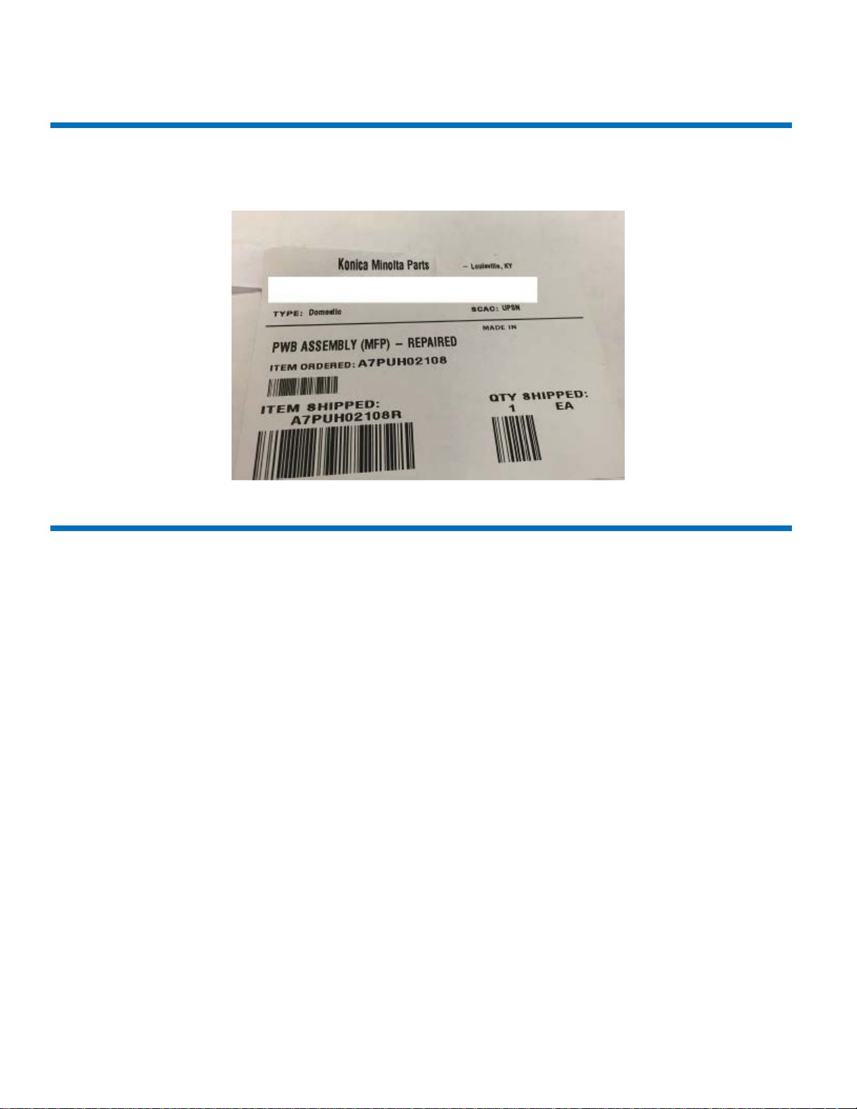
4. If the MFPB actually needs to be replaced, it may be necessary to flash the machine with the reset tar file
“a789be.tar” if it was a “repaired” or “cleansed” board. See below regarding how a repaired board will be labelled.
ERROR CODE ISSUE
1. CD0010/CD0011/CFA14 errors.
• Reference Bulletin 10072
o Use firmware
o Recovery GXX-A8
o Preventive GXX-B0
• GC1-A7 has been released addressing CFA14
o Always reference and follow the installation instructions that accompany new firmware.
2. CC-163/CC-164
• With the repaired MFPB installed in the machine, please do the following
o Flash the machine with G00-16 firmware
o Put GG9-84 firmware on USB drive, hold down the Reset button, (C258/C308/C368 only)
o Go through the screen calibration
o When firmware screen appears, at the bottom right you will see Boot Rom, select it and update boot
Rom only.
o Remove USB drive and boot machine.
Note:
If EEproms have also been replaced, you may need the original CSV file to recover from this condition.
Please call the contact support Center (CSC)
.
7

bizhub C258/C308/C368/C458/C558/C658 Troubleshooting Guide
FIRMWARE ISSUE
1. USB sticks suitable for use for F/W upgrades.
• Bulletin 10072 has a link for approved USB drives KBA00026635 for list.
• Unable to load firmware reference KBA 00 026634
CAUSE: Incorrect placement of front USB cable and/or incorrect procedure for loading firmware.
SOLUTION: Check placement of “Front USB” cable
8
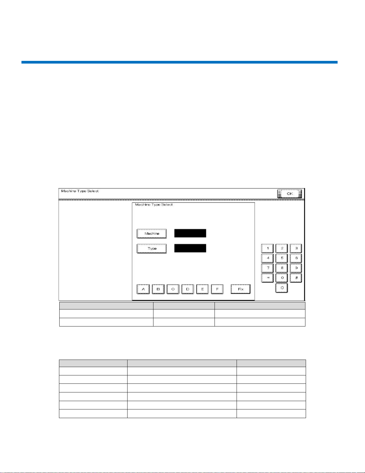
First four digits of the serial number
A7PU
A7PY
[Machine]
6 6 [Type]
1
2
Serial Number
Machine
Type
A79J 9 7
A79K 9 9
A79M 9 0
A7PU 6 1
A7PY 6 2
A7R0 6 D
bizhub C258/C308/C368/C458/C558/C658 Troubleshooting Guide
FIRMWARE ISSUE (Cont.)
After cable is checked for proper position, perform the following:
1. Prepare USB drive, (This procedure outlines how to load a single version.)
A. Format USB drive in FAT 32. See attached instructions.
B. Extract the firmware onto the PC.
C. Copy the entire “FW0002” folder to the root of the USB drive.
2. Firmware upgrades
• Failure to perform firmware upgrades correctly can result in corrupt MFPB.
o Always reference and follow the installation instructions that accompany new firmware.
3. When flashing firmww are or replacing the MFPB, always check and set the [Machine] and [Type] as listed below.
Enter [Machine] and [Type] information according to the following table. Then touch [Fix].
Note: The [Machine] and [Type] values should be set by referencing the first four digits of the MFP’s “Serial Number”
located on the serial number plate on the back of the machine (not the model).
9

bizhub C258/C308/C368/C458/C558/C658 Troubleshooting Guide
4. When replacing EEproms for any reason, load base 16 firmware followed by every base firmware after that.
.
5. In Service mode, before replacing the transfer belt and fusing unit, clear the counters.
Note: Since the counters will be cleared when the EEprom is replaced with a new one, replace the following with
new parts:
• Developing Units Y,M,C,K
• Drum Units Y, M, C, K
• Toner Cartridge Y, M, C, K
• Transfer Belt
• Fusing Unit
• Transfer roller
6. Perform the following adjustments in this order (Service manual 5.4.4)
Note: Ensure the front door is open.
Note:
Conduct the readjustments listed above before starting the initial warm-up operation, after replacing the
EEproms.
10

C-DFA0 (ASIC image access failure)
1. Symptom
Trouble Code C-DFA0 (ASIC image access failure) occurs frequently in machine setting up.
Procedure
A. Touch “Auto Stop Position Adjustment” in the ADF/ Service Mode.
B. Perform the items listed below many times.
• Sub Scanning Direction 1-side
• Sub Scanning Direction 2-side
• Main Scanning Direction (Front)
• Main Scanning Direction (Back)
C. After performing the items listed above, make a copy.
D. Trouble code C-DFA0 con ti nues t o occ ur .
2. Cause
Firmware (FW) bug
Trouble code C-DFA0 occurred when error bit appeared in the FW.
3. Measures
3-1 Counter measure
Turn off the main power SW and wait for 10 seconds or more before turning on.
3-2 Preventive measure
The firmware was modified and released on the CSES site.
DLBT1509417EN
4. Model
DF-629/DF-704
bizhub C258/C308/C368
11

Paper full Message on exit tray 1
1. Symptom
There is a possibility that paper full message appears for exit tray 1
bizhub C258/C308/C368
2. Cause
Condition:
C368/C308/C258 and JS-506 combination, using upper side tray for JS-506
Using paper: Kan net pa per ( A4: 64g/m2) Japanese paper
The paper with low rigidity would not discharge to the upper exit tray. The paper would stop in the vicinity of the
paper exit roller. An over capacity condition resulted after several sheets were discharged.
12

3. Measures
Modify the two-upper (centered) paper exit rollers on the upper side.
To improve paper conveyance so paper does not stop in the vicinity of the paper exit roller.
bizhub C258/C308/C368
4. Model
C368/C308/C258/+JS-506
The PMN (Parts Modification Notice) was issued to the field.
PMN # KOM16121
13

The speaker volume was difficult to hear
1. Symptom
The speaker volume was difficult to hear from this machine when the bank balance was checked by on-hook mode.
2. Cause
The output signal is different from the Fax modem and the C384 series and could not be amplified to the maximum
level. The speaker volume was difficult to hear when the signal output changed.
3. Measures
To modify the 3 resistor (R358, R361, and R1301) values on the MFP board, as a result, to improve the speaker
volume.
4. Model
C368/C308/C258
The PMN (parts Modification Notice) was issued to the field.
PMN # KOM162399, BEU only: KOM162253
Fusing offset image
1. Symptom
Fusing offset image
Condition
• Finisher not installed
• Sleep Mode Settings: Yes
• Tray: 1
• Paper: A4 LEF, 140mm solid color has leading edge on A4 LEF.
Procedure
A. When this machine enters sleep mode and the cooling fan stops after 3.5 s econds, a print job is sent from
a PC.
B. The Fusing offset image occurs.
2. Cause
• Firmware bug
• The fusing rollers are warming up in retraction mode
• The print job is sent to the machine from the PC when the fusing roller is warming for 300ms.
• The problem condition is during the following modes:
st
Tray
o PC printing
o Fax received and return to low power mode
bizhub C258/C308/C368
14

3. Measures
3-1 Counter measure
A. Input #13 Engine FW DipSW
B. Access Service mode
C. Access Enhanced security mode. (*1)
D. Set #13 Engine DipSW. (*2)
(*1) Enhanced security mode: Press the “Stop key” -> “0 ’ -> “C” while in service mode.
(*2) Engine FW DipSW: Press the “System 2” -> “Engine FW DipSW” -> 13.
Turn OFF/ON the main power switch, SW1.
3-2 Preventive measure
• The modified FW (Special FW) released the end of October, 2016.
DLBT1615717EN
• The modified FW (MR FW) released the end of January, 2017.
DLBT1617775EN #82
4. Model
C368/C308/C258
bizhub C258/C308/C368
15

bizhub C258/C308/C368
Frequent jam code(s) J20-01, J20-02 (Misfeed at vertical transport section)
1. Symptom
When the claw of the cover (A161160403) was damaged, error code J20-01, j20-02 occurs frequently.
2. Cause
The claw for the cover doesn’t get damaged under normal use, but prolonged use with repeated opening/closing
the vertical transport door, the claw may become damaged over time.
3. Measures
The claw has been modified as illustrated below.
16

bizhub C258/C308/C368
Notice of setting the FK-513/514/515
1. Symptom
There is a possibility that the initialization doesn’t perform correctly. Fax transmitting and receiving fail.
2. Cause
The install manual was wrong for the FK-513/514/515.
3. Measures
3-1 Counter Measures
Add the item for FK-513/514/515. The detail items are as follows:
A. Plug the power cord into the power outlet and turn on the power switch.
B. Access the service mode screen, (refer to the Service manual details on accessing the service mode).
C. Select “System 2”.
D. Select “Optical Board Status”.
E. Select “set” of Fax (circuit 1).
F. Select “End”.
G. Turn the power switch OFF and ON. Refer to the detailed notice listed below.
<Notice>
Exit the Service mode screen, turn OFF the power switch.
After 10 seconds, turn ON the power switch again.
When “Preparing User Box…” and “Preparing Scan/Fax…” messages are gone, the messages on the display,
please set “Marketing area” and “initialization” for FK-513/514/515 appear.
3-2 Permanent Measures
The install manual will be modified as listed above (Counter Measures) for FK-513/514/515.
4. Model
FK-513: bizhub 367/287/227
FK-514/515: bizhub C368/C308/C258
17

Effective Serial Numbers (S/N)
Machine
BUS (001)
BEU (021)
BCN/BSA/BAU (041)
C368
A7PU011001401 and above
A7PU021002726 and above
A7PU041000025 and above
C308
A7PY011001984 and above
A7PY021003841 and above
AYPY041000175 and abov e
C258
A7R0011000001 and above
A7R0011000001 and above
A7R0041000001 and above
Installation of FK-514 is difficult
1. Symptom
It is difficult to insert FK-514 in the area of the Guide plate and fax frame.
2. Cause
The problem is due to the gap between the Fax frame and the Guide plate as illustrated with the red elliptical in
bizhub C258/C308/C368
figure #1.
3. Measures
The Fax frame and Guide plate no longer have a gap as illustrated below. Refer to the red line marking.
4. Model
C368/C308/C258 & FK-514
18

No Fax Reception
1. Symptom
The following symptoms can be seen when the MFP is in Low Power Mode / Sleep Mode (*hear after it is called
“Power Save Mode”).
A. Cannot receive Fax
B. Cannot recover from Power Save Mode by Power Save Mode release operations.
2. Cause
When the multiple Power Save Mode release operations are done, for example, set an original on the ADF and any
keystrokes, the command for the second operation, keystroke in this case, cannot finish completely and cannot
recover from Power Save Mode. As a result, it cannot receive any Fax afterwards.
3. Measures
Modify the power sub-CPU from ver. G00-07 to Ver. G00-10 and above.
Other issues were modified FW, too. Released FW (DL No.DLBT1509417EN) on the CSES site
Current Ver. G00-16 -> New Ver. G00-54
4. Model
bizhub C308/C368
bizhub C258/C308/C368
• Power Save Mode release operations:
o Fax reception, origi nal pap e r set on ADF, Front Door open/close, CSRC Modem reception,
print out from IC-418 controller, motion detection sensor activation, key operation, WiFi
connections.
(Remarks)
No problem printing from a PC during the Power Save Mode.
No problem receiving a fax after recovering from Power Save Mode.
By pressing the power button, it recovers from Power save Mode.
By turning the power switch off/on, it recovers from the abnormal condition.
19

bizhub C258/C308/C368
Handling Instructions for SC-508
Caution
When the Security Kit SC-508 has been installed, ensure that the cables do not contact the DSC board/2 (backside) when
attaching the connectors. Refer to the illustration below.
Model combination
C368/C308, DF-704 & SC-508
20

bizhub C258/C308/C368
How To
ID: KBA00034336
How to safely remove an EEPROM
When EEPROM’s need to be replaced, pulling on them with your fingertips can bend, break, or damage the pins.
Models
C658/C558/C458/C368/C308/C258
C3350/C3850 Series
C3351/C3851 Series
Please remove the EEPROM slowly by using a small standard flat-blade (nylon) screwdriver.
21

bizhub C258/C308/C368
1. Using a small standard or “flat-blade” (nylon) screwdriver, insert it under the EEPROM and shimmy back and forth
until the EEPROM is almost completely off. Slowly and firmly extract it from the board.
2. Make sure the “Flat” end of the screwdriver is small enough to fit in between the
two sides of the pin. See the image below to determine if the flat end is small
enough to use.
3. Once you’ve found the proper screw driver, please place in underneath the EEPROM and shimmy back and forth.
4. When the EEPROM and pins become loose off the Main board, please use a firm grip and extract the EEPROM by
pulling straight up.
5. Note: Please use a NYLON flat head screwdriver to extract the EEPROM. Using a metal screwdriver could damage
or break the EEPROM. It is recommended you purchase or use nylon screwdriver.
22

Self-Diagnostic Function
Reference
ID: KBA01400523
The Self Diagnostic function performs a diagnostic check for the following.
DIMM R/W Check
On Board Memory Check
SSD Check
HDD Check
Compression/Decompression Check
Memory Bus Check
Fax Board Check
LAN Check
USB Check
Note: If a particular test fails the diagnostic check an NG will be indicated.
Prerequisites
Please install the latest firmware.
Procedure (using SERVICE MODE menu)
1. Call the Service Mode to the screen.
2. Touch these keys in this order: [State Confirmation] g [Self-di ag nos ti c] g [Ch eck All ].
3. Press the Start key to start the check procedure.
4. When the check procedure is completed, the results are shown on the screen. If any of the check results are NG, take
measures upon confirmation of the corruption details mentioned above and Next action.
Note: Press the Stop key to interrupt the check sequence.
Procedure (using main power switch)
1. Open the front door.
2. Turn the main power switch ON while pressing the power key. After a short beep sound is made once, release the power
key and close the front door. Wait to display the self-diagnosis (full check) screen.
3. After displaying the self-diagnosis screen, press the start key. The self-diagnosis (full check) is started. The result of the
diagnosis is displayed for every item. (OK/NG)
4. After finishing the diagnosis for all items, turn the main power switch OFF.
5. If there is an item displaying NG, investigate the NG item and take countermeasures.
23

Individual Diagnostic checks
Check mode
Check details
Corruption details
Next Action
DIMM R/W Check
• Execute Read/Write Check
[Memory Check].
• DIMM on the MFP board
• Reseat DIMM.
On Board Memory Check
R/W Check
Execute Read/Write Check
MFP board.
• Corruption of On Board Memory
• Corruption of battery
Replace the MFP board.
Pattern Check
Execute Read Check for the
• The pattern data for test cannot
electrical parts occurred.
Replace the MFP board.
SSD Check
R/W Check
Execute Read/Write for t he
• Connection failure of the SATAI/F
• Corruption of MFP board
• Reseat the SSD board.
Pattern Check
Execute Read Check for the
• The pattern data for test cannot
electrical parts occur red.
• Reseat the SSD board.
HDD Check
R/W Check
Execute Read/Write for
• HDD cable failure
• Check the HDD cable
• Replace the MFP board.
Self-diagnostic
Check whether the
HDD and MFP are normal.
Evaluate OK if there is any response
is no response.
Check the HDD cable connection.
Self-diagnostic
Execute the buffer test and
reserved area for the test.
Retrieve the test log, and display
Replace HDD.
Compress/Decompression Check
?MFP Board
Execute the
Corruption of the compressed/
Replace the MFP board.
for DIMM on the MFP board.
• Execute the same check as
[Rough Check] under
[Memory/HDD Adj.] ->
for On Board Memory on the
pattern ready written in the
area secured in On Board
Memory on the MFP board
for Read.
SSD board
pattern ready written in the
area secured in SSD.
• Corruption of CPU
on the MFP board
be read because the pattern data
for test has been rewritten, or a
contact failure of the electrical parts
occurred.
• The correct information cannot be
read because the data in the area
for Read has been modified due to
software failure or a failure of the
connector of the SSD board
• Corruption of SSD device
be read because the pattern data
for test has been rewritten, or a
contact failure of the electrical parts
occurred.
• The correct information cannot be
read because the data in the area for
Read has been modified due to
software failure, or a failure of the
• Check the connectors on the MFP
board.
• Replace the SSD board.
• Replace the MFP board.
• Replace the SSD board.
(I/F Check)
(Memory Check)
HDD.
communications bet ween
the media test.
• Buffer test
Execute Read/Write Test for
the buffer memory of HDD.
Transfer the data by DMA to
check whether the buffer
memory works normally.
• Media test
Execute Read/Write Test for
the disks of HDD. Check
whether the disks, motor, and
head works normally. Use the
• HDD failure
• MFP board failure
returned from HDD, and NG if there
existence of error.
connection.
• Replace the HDD cable.
• Replace HDD.
24

compression/extension test
for the MFP board.
extended circuits or memory of
MFP.
DS Board
Execute the
compression/extension test
for the DS board.
Corruption of the compressed/
MFP board.
• Remove and insert the DS board.
Fiery I/F Board
Execute the
• Connection failure of the fiery I/F
Fiery I/F board.
• Remove and insert the Fiery I/F
Memory Bus Check
?Input Image Bus Check
Execute the input image bus
• Connection failure of the CCD I/F
circuit or image bus of MFP board.
• Check the connections.
Input Image Bus Check (CIS)
Execute the input image bus
• Connection failure of the DS board
circuit or image bus of DS board.
• Check the connections.
• Replace DF.
Output Image Bus Check
Execute the input image bus
test for the MFP board.
• Corruption of the input image
circuit or image bus of MFP board.
Replace the MFP board.
FAX Board C heck
• Execute the FAX board test.
• Connection failure of the cables
• Replace the FAX signal cable.
• Replace the MFP board.
LAN check
Execute the Ping test.
• The network is faulty.
cable due to breakage of the cl aw.
• Correct the network of the unit.
USB check
Execute the test to check
• Connection failure of the USB
device.
• Replace the MFP board.
extended circuits or memory of
• Replace the DS board.
(CCD)
compression/extension test
for the Fiery I/F board.
test for the MFP board.
test for the DS board.
• Execute the data
transmission sound test.
board connector.
• Corruption of the compressed/
extended circuits or memory of
connector.
• Corruption of the input image
I/F connector.
• Corruption of the input image
connected to the FAX board.
• Failure of the FAX board.
• Corruption of the LAN connector
of the MFP board.
• Connection failure of the LAN
board.
• Replace the Fiery I/F board.
• Replace the CCD cable.
• Replace the MFP board.
• Replace the DF cable.
• Replace the DS board.
• Replace the FAX power supply
cable.
• Replace the FAX board.
• Replace the MFP board.
• Replace the LAN cable.
whether the USB board
operates normally.
connector of the MFP board.
• Connection failure of the USB
• Replace each USB device
(authentication device, etc.).
Note: For additional detail please refer to the Adjustment/Setting section of the Service Manual 12. Service
Mode 12.18.12 Self-diagnostic.
25

C9401 (refresh models ONLY)
Known Error
ID: KBA00034462
Error
C9401 after updating firmware
Root Cause
Firmware mismatch occurs with new style CCD unit installed.
Workaround/Fix
Install firmware version G00-Q4 or newer.
Refresh Model Serial Number Cut-ins
• bizhub C368 (refresh model) A7PU017xxxxxx
• bizhub C308 (refresh model) A7PY017xxxxxx
• bizhub C258 (refresh model) A7R0017xxxxxx
• bizhub C227 (refresh model) A798017xxxxxx
• bizhub C287 (refresh model) A797017xxxxxx
• bizhub 227 (refresh model) A7AK017xxxx xx
• bizhub 287 (refresh model) A7AH017xxx xx x
Technical Notes
The latest version firmware is available for download via One Stop Product Support.
26

How to obtain Log files from the MFP
How To
ID: KBA00032414
Question
How to obtain Logs from a MFP?
Answer
See the four methods of obtaining a Log File from the MFP. Also attached is the Log Key File create tool.
In some instances you will be instructed to gather logs from our products. Obtaining the Log Files is a critical
part of diagnosing complex machine specific issues. This document outlines four methods to gather logs:
1. USB method
2. HDD method
3. Tera Term
4. Debug Log
1. USB Method
Save Logs onto a USB drive with a KeyFile and Command file pressing the Operation Panel
Preparation:
Set (Export Debug) to allow in Administrator/Settings/Security Details/ (Page4)
Save Debug folder on USB memory
After anomaly happens press the hard key 2 for 4 and e series and 3 for 7 and 8 series machines on the
operation panel for more than 5 seconds, Log acquisition starts immediately after releasing the key.
Data light blinks during the log acquisition, log takes about 3 minutes to complete.
MFP will reboot after acquisition is complete
Remove the USB memory. (see the following pages for detailed instructions).
27

How to obtain Log files from the MFP
`
ESS 6/29/2017
28

How to obtain Log files from the MFP
29

How to obtain Log files from the MFP
For PC method, USB memory can collect logs with specific log commands. This enables the filed staff
To collect logs on the spot without a PC/laptop. Different from the HDD method, USB memory method can
collect operation logs, TroubleLogAll and SysLogAll on the USB memory.
<Models and FW version>
Bizhub C554e/C454e/C364e/C284e/C224e/554e/454e/364e/284e/224e
Gxx-C8 or later
Bizhub C754e/C654e/754e/654e
Gxx-E4 or later
The specific files must be prepared in the USB memory to collect logs with USB memory. 2 Files are required,
one is Key File having the serial number information of the MFP and another is the Command File for log
collection.
Save a command file in USB memory.
Insert USB memory to MFP’s USB Port used to rewrite firmware.
Keep pressing the ‘2’ key (for 4 and ‘e’ series) and ‘3’ key (for 8 series) for more than 5 seconds and then
Release it.
*Log acquisition starts immediately after releasing the key.
*Blue data LED on MFP blinks while saving the log files to the USB.
MFP automatically reboots after finishing log collection; Pull out the USB memory after the reboot is complete.
30

How to obtain Log files from the MFP
2. HDD Method
Precautions:
Up to 10 logs (maximum) can be saved on the HDD, and if the number exceeds this amount, logs
will be deleted in turn from oldest to new est (R ol li n g lo g) .
Automatically saves a log file which is the equivalent to TroubleLogAll command on HDD triggered
By the trouble code event.
The Log is not automatically saved without a trouble code
In auto save mode during the time the SysLog is being saved on the HDD after trouble event the machine will
not reboot.
Setting Prep (auto sa ve):
1. From the MFP panel, go to [Service Mode] -> [System Setting 2] -> [Software SW Setting],
2. Change switch settings as follows and press the [Fix] button.
3. Set Software Switch 18 to Hex05 in Service mode/System 2/Software switch
*After switch values are set, when the Hex value changes to 80, auto save setting is completed. *In
order to reflect software SW changes, after changes are made, turn the main power OFF/ON.
Saving:
Trouble code happens!
1. Do not power off for two minutes after the trouble code appears. The Log capture could be incomplete
when the MFP has its main power turned off immediately after occurring trouble.
2. Insert the USB memory into the MFP’s USB port used to rewrite FW
3. Confirm that the USB is connected to the MFP, and from the MFP panel go to [Service Mode] ->
[System Setting 2] -> [Software SW Setting].
4. 'Change switch settings as follows:
a. SW-No.: 18 HEX: 03
b. USB memory starts to save log after pressing [Fix]
c. It will take only several seconds for the log to be saved.
5. Check if [SLALL"date"_00_trouble code] file is saved in USB memory
6. When the log completes writing to the USB Stick, please return the dipswitch to the original value>
[Hex] turns to "80" or "00"
7. File name example SLALL140619165431_00_FA14.log
31

How to obtain Log files from the MFP
How to reset after log acquisition
After obtaining the log file, go to [Service Mode] -> [System Setting 2] -> [Software SW Setting] and
change settings to the values shown below or return to original settings, and press [Fix]
SW-No.: 18 HEX: 04
Reset is completed when the Hex value changes to 00
In order to reflect the changes made in software SW setting, turn the main power OFF/ON after making
changes.
3. Tera Term:
Preparation:
Serial console crossing cable (RS-232)
PC with serial connection (Please install "Tera Term (*1)" and Wireshark in advance)
We recommend high spec PC such as Core Duo to collect both network packet and MFP logs at
the same moment.
Repeater HUB for capturing packet
Tera Term can download from the following Web site.
http://ttssh2.sourceforge.jp/index.html.en
Software Switch Setting on the MFP
Switch 19 set to Hex 81
If Vendor equipment is connected to MFP Set Hex to 03
Please set time and date correctly on PC and MFP
32

How to obtain Log files from the MFP
Tera Term Installation:
After download Tera Term execution file, please install it with the following procedure
It is not necessary to select Compact Installation (Simple screen Shot)
33

How to obtain Log files from the MFP
End of Tera Term Installation
Tera Term Use
Open Tera Term and the New Connection dialog box is displayed.
34

How to obtain Log files from the MFP
Tera Term settings to communicate with MFP
Please set in advance before you correct Continuous SysLog or SysLogALL or TroubleLogA LL.
Run Tera Term
After running Tera Term, the following screen may s how.
Select "Setup" tab, and select "General..."
In this dialog, select Language as "Japanese". And select OK button.
Select "Setup" tab and select "Terminal..."
35

How to obtain Log files from the MFP
Change character code of Kanji [receive]" and "Kanji [transmit]" as follows; UTF-8 -> SJIS
Select "Setup" tab and select "Serial port..."
Select Baud rate as "115200". And select OK button.
After the above settings, the following under line will be changed from "9600baud" to "115200baud"
If you want to SAVE the above settings, please select "Setup" tab and select "Save setup.
36

How to obtain Log files from the MFP
On TeraTerm, Select "File" -> "Log...".
Enter filename and select save folder and select Save
Connect your PC/Laptop to the MFP using a Serial cable.
Start the Tera Term session, Turn MFP ON and enter either the SysLogALL or TroubleLogALL command after
the console stops from machine boot up.
When code occurs, allow the Tera Term to run for at least 20 to 30 minutes or until the logging stops
37

Method
Priority
Information
Time for Trouble
Log/ALL
Characteristics
Restriction
Log acquisition
1
Precise
5 minutes
Requires only USB memory (PC-less)
Need to set Software SW before
Information Acquisition Guide.)
HDD log saving
2
Precise
6 minutes
Save information similar to
Both for Manual Save and Auto
“Internal Error Auto Cancel” is set.
How to obtain Log files from the M FP
4. Debug Log:
How to gather a debug log is located in all manuals,
2.11.15 Security Settings – Debug Log Encryption Settings
(1) Debug Log Encryption Settings
(A) Use
To set a password used to encrypt de bug data when storing it into the HDD.
(B) Default setting
01234567890123456789
(C) Procedure
Enter an encryption passphrase from the on-screen keyboard.
1. Enter the encryption passphrase currently in use.
2. Encryption Passphrase: Enter new encryption passphrase.
3. Encryption Passphrase Confirmation: Re-enter the new encryption passphrase.
The above information is from the C368 service manual.
Export Debug Log:
Set Software switch 155 to Hex 01, Service mode>System2>Software Switch Setting
Characteristics and restrictions
using USB
memory stick
function
Save log quickly
Troublelog/ALL into HDD in two ways:
1. Manual Save: Triggered manually
by CE’s operation without preparation
needed.
2. Auto Save: Triggered automatically
by detecting a trouble code.
taking log
Need to prepare key file and
command log files in USB memory
Need to acquire log after occurring
issue without turning main power off.
Not possible to take log when MFP
is in Power Save mode, or in Sub
Power OFF.
Need supported FW version (Refer
3.4.3 Support model and FW of Log
Save.
Maximum 10 logs can be saved in
HDD. If the number exceeds the limit,
older logs will be deleted.
For Auto Save:
Need to set Software SW before
taking a log.
Possible to acquire log only when
trouble code occurs.
Require USB memory to collect log.
MFP does not reboot automatically
while saving a log (max 6 min) even if
38

Method
Priority
Information
Time for Trouble
Log/ALL
Characteristics
Restriction
Log Acquisition
3
Precise
60 minutes
Requires PC and RS-232C cable
Need to set Software SW before
set.
Debug Log
4
Simple
-
Save log automatically into HDD when:
[All] - > [Shared Memory - > HDD].
Need to set Software SW before
using a PC
Acquisition
The Log Key file create tool is available at the:
Possible to save logs of various
symptoms consistently.
There is no job remaining at the end
of the job.
Detecting a trouble code.
Entering Power Save mode.
Authentication fails
Manually starting by [service Mode] -
> [Debug Settings] - > [Debug Log
Output] - >
taking a log.
Need to acquire log after occurring
issue without turning main power off.
bizhub 367 Series and bizhub C287
series, an optional unit connector for
CS remote Care to be purchased and
attached except Asia Pacific and
Europe where the unit is standard
taking a log.
Information log is less than other
logs. It is not possible to find a cause
of the problem with this log in many
cases.
Log into My Konica Minolta -> Service -> One Stop Product Support -> Quick Search “Log key file create”.
39

How do I confirm that the content in a Log gathered is correct?
How To
ID: KBA00035540
Question
How do I confirm that the content in a Log gathered is correct?
Answer
With this Log Analysis Tool you can confirm that the gathered log is valid. Please see attached document and Tool
See the information listed below for:
• Log analysisTool_v1EN.doc
•
Log Analysis Tool_v1.x ls
Note: To use the Log Analysis Tool_v1.xls, log into My Konica Minolta -> Service -> SSD Home Page -> Solutions ->
Access the Knowledgebase -> Search SSD Knowledgebase -> KBA00035 540 -> click on the attachment.
Log analysis Tool_v1EN.doc
Abstract
“Log Analysis Tool_v1.xls” can be used to confirm the following content from the log that’s obtained from the MFP.
• Is the troubleshooting code included in the log?
• Is the log of the command log outfitted completely?
• The change of MFP power status
• The content of the executed job in MFP
By using this tool, it is possible to confirm whether the log is obtained during the problem occurrence or not. Also, this tool is
useful when creating a test mode for the reproduction test.
1/26/2018
Ver. 1.0
OP Support Division, Customer Support Business Operations
Konica Minolta, Inc.
40

Contents
1. Requirements for using this tool
2. How to Use This Tool
2.1 Display language Selection
2.2 Log File Analysis Procedure
2.3 Way to delete Log File Analysis Result
2.4 Way to Save Analysis result
3. About Execution Result
3.1 Details Shown in “3. Execution Result” of “Log Analysis” sheet
3.2 Details Shown in “Realtime log Information” sheet
3.3 Details shown in “Command log Information” sheet
4. Caution and Restrictions
41

1. Requirement of Using This Tool
• Necessary Application
Windows Microsoft office Excel
• Supported models
bizhub C754e Series, bizhub C554e Series, bizhub C364e Series
bizhub 754e Series, biz hu b 554e Series
bizhub C759 Series, bizhub C658 Series, bizhub C368 Series, bizhub C287 Series
bizhub 958 Series, bizhub 658e, bizhub 368e, bizhub 558 Series, bizhub 367 Series
• Analyzable Logs
Real-time log and the logs obtained via TroubleLogALL command and SysLogALL command
2. How to Use This Tool
Startup [Log Analysis Tool_ v 1] and operate the following steps.
2.1 Display Language Selection
1. Select either “Japanese” or “English” for “Language” in “Log Analysis” sheet.
The display language will be changed automatically according to the language that is chosen.
2.2 Log File Analysis Procedure
1. At “Log Analysis” sheet, select the correct product of the log file you wish to analyze.
Caution: If the product of the log file is selected wrongly, the analysis result might be inaccurate.
2. Click “Analysis” button.
The dialog of file selection will be shown. Choose the file that you wish to analyze.
3. Wait until the analysis is complete. The progress status is shown at the bottom of Excel.
42

4. The analysis result is shown in the following sheets.
• “3. Execution Result” in “Log Analysis” sheet
• “Realtime log information” sheet
• “Command log information” sheet
[Note]
If the log analysis fails, the error message will be shown.
2.3 Way to Delete Log File Analysis Result
Make the following step if you wish to continue with the log analysis.
1. Click “Reset” button.
Immediately after clicking it, the results shown in the following sheets will be deleted.
• “3. Execution Result” in “Log Analysis” sheet
• “Realtime log information” sheet
• “Command log information” sheet
2.4 Way to Save Analysis Result
1. Click “Save” button.
Immediately after clicking it, a new excel named will be created and the results written in the following sheets will be
copied. This new excel file will be named as ”[Log File Name]_Result.xlsx” saved in the same location (folder) with the tool.
• “3. Execution Result” in “Log Analysis” sheet
• “Realtime log information” sheet
• “Command log information” sheet
43

Category
Item Name
Content
File
File Name
Show the file name that has been analyzed.
Log acquisition
Show the log acquisition method that is used by jud ging from the file name
Realtime log
Is there any
Show the availability of the T er aT erm ’s timestamp.
Log Acquisition
Show the start time and end time of the timestamp if there is TeraTerm’s
Is there any trouble
Show the trouble code if there is a trouble code detection log included in
※
Command log
Is there any
Show whether the command log is included or not.
Is the command log
Show whether the log output is done completely or not. (*1)
Log command input
Show the date and time that the log command has been inserted. (*3)
MFP Name
Show the model name that the log was acquired.(*3)
MFP Serial No
Show the serial number of the log acquisition MFP. (*3)
Firmware Version
Show the firmware version (card version) of the log acquisition MFP. (*3)
IP address
Show the IP address of the log acquisition MFP.(*3)
Is there any trouble
Show the trouble code if there is a trouble code detection log included in
3. About Execution Result
3.1 Details shown in “3. Execution Result” of “Log Analysis” sheet
The summary information of the log file is shown in 3. “Execution Result”. The following items are described in this part.
information
information
information
method
TeraTerm's
timestamp?
Period
occurrence?
command log?
acquired properly?
like the followings.
PC(TeraTerm), Save log to HDD(SW18), Log acquisition using USB
memory, Debug log collecting system(SW155)
timestamp.
the realtime log.
The trouble code unrelated to MFP controller cause is not able to
be detected.
Detectable log commands are TroubleLogALL, SysLogALL c om m and onl y.
date and time
The model name points to the development name.
occurrence?
*1: If more than one log command is involved in a log file, it will be judged as failed in the condition where either
one of them is not acquired correctly.
*2: If more than one log command is involved in one log file, only the result regarding to the first log command will
be shown.
*3: If more than one log command is involved in one log file, only the result of the last log command will be shown.
the command log.(*2)
44

Item Name
Content
Number of log file lines
Show the number of lines on the file corresponding to the displayed log.
PC's Timestamp
Show TeraTerm’s timestamp corresponding to the displayed log.
Content
Show MFP power status, executed job information, trouble information and
command input information that are extracted from the realtime log.
Log Excerpt
Show the corresponding log extracted from the displayed log.
Tick
Show the time of MFP system.
Item Name
Content
MFP Time
Show MFP time corresponding to the displayed log.
situation.
Tick
Show the time of MFP system.
Summary
Show the outline of the displayed log.
Job No
Show job No. when there is a log related to the ongoing/executed job.
Content
Show MFP power status, executed job information, and trouble information.
Log Excerpt
Show the corresponding log extracted from the displayed log.
3.2 Details shown in “Realtime log information” sheet
The summary of the realtime log extracted from the log file is shown. The content of the following items is described in this
sheet.
3.3 Details shown in “Command log information” sheet
The content of the command log included in the log file is shown. The content of the following items is described in this
sheet.
It is shown in time series order but 1 second error difference might occur
sometimes. As a result, following the order of the MFP time may not be
appropriate.
However, the displayed order is the correct order of the time series during this
4. Caution and Restriction
• Do not delete the following sheets as it will cause the failure of log analysis.
○“Log Analysis data” sheet
○“Log Analysis List” sheet
• If the name of the log file obtained through Save to HDD (SW18) or Debug log Collecting System (SW155) is been
modified, log analysis might fail because it may not be recognized it correctly.
• If the log garbled, the analysis might fail.
• If you wish to continue with another log file analysis, click [reset] to erase the previous execution result and then
only proceed with the next log file analysis.
45

MFP Log Acquisiti o n Tool
How To
ID: KBA00035539
Question
How do I gather a log properly for a machine?
Answer
This tool is a support interface to make the procedure to get a log acquisition simpler and easier for anyone. By the
occurrence of any trouble code like C-E301 as a trigger, automatically any command like “TroubleLogAll” is executed to
perform the log acquisition.
See attached document and Tool
46

IT4(e) Series / IT5
How can I check if my software switches are set to factory sett ings?
How To
ID: KBA00035542
Question
How can I check if my software switches are set to factory settings?
Answer
Use the attached Software SW Settings Checking Tool,
Note: To use the Software SW Setting Checking Tool, log into My Konica Minolta -> Service -> SSD Home Page ->
Solutions -> Access the KnowledgeBase -> Search SSD Knowledgebase -> KBA00035542 -> click on the attachment.
User Guide
Software SW Setting Checking Tool
Abstract
“Software SW Setting Checking Tool_v1.xls” is used to confirm the following points from the software SW setting of
machine management list (CSV file).
- Is it the default value?
- What is the default value?
- The difference of the software SW setting between the MFPs.
Use this tool when checking the software SW setting is required.
2018/1/26
Ver.1.0
OP Support Division, Customer Support Business Operations
Konica Minolta, Inc.
47

Contents
1. Requirement of Using This Tool.
2. How to Use This Tool
2.1 Display language Selection
2.2 Machine management List Loading
2.3 Software SW Settings Checking
2.4 Way to Erase the Loaded Data and Check Result
3. Caution
4. Restriction
48

1. Requirement of Using This Tool
・Necessary Applica tion
Microsoft office Excel 2007 or newer version
・Machine Management List
“S1_***.csv” file that obtained from the supported models using USB save.
[Service Mode] > [List Output] > [Machine Management List] > “USB SAVE“
・Supported Models
bizhub C754e Series, bizhub C554e Series, bizhub C3 64e Ser ies
bizhub 754e Series, bizhu b 554 e Seri es
bizhub C759 Series, bizhub C658 Series, bizhub C368 Series, bizhub C287 Series
bizhub 958 Series, bizhub 658e, bizhub 368e, bizhub 558 Series, bizhub 367 Series
2. How to Use This Tool
Startup [Software SW Setting Checking Tool_v1.xls] and operate the following steps.
2.1 Display Language Selection
1. Press [Language Selection] in “Check” sheet.
In the following case, the language will be switched from Japanese to English.
* Do not de lete the content (Eg. : “Language: English”) written in K1 cell. SW checking cannot be proceeded
successfully due to the cell deletion.
49

2.2 Machine Management List Loading
1. Click [Select MML file (S1_***.CSV)] button to select [S1_***.csv] file.
After clicking “Open”, the file starts loading
and the result like below will be shown.
* Caution *
If the marketing area is not inserted , select it manually.
If the product name is not shown, insert the product code (the first 4 digits of Serial Number) in Serial Number
column.
50

2.3 Software SW Settings Checking
1. If you wish to make the comparison of the software SW setting between MFPs, insert the HEX of the software SW in
“Data to Check” column in advance.
2. After finished doing the step written in “2.2Machine Management List Loading”, click “DipSW
Check” button.
After the checking completed,
the result will be shown.
51

Display Items
Contents
Default Check
Show ”Default” if it is in default value.
default value if it is not in default
value.
Function[
Show the SW function outline if the related data is recorded in Definition
it will not be shown if the setting is in default value.
00 or the default setting
varies according to the products and function versions, the function
outline will be shown even if it is in default setting.
Value Content
Show the content of the set value for each function.
Result of [Data to
The comparison result of HEX value between two MFPs.
- : The comparable data does not exist.
Details shown in the result]
Result
Show ”Not Default” together with the
sheet.
* Basically,
However, if the default setting value is not 0x
Check]
OK : Same
NG : Different
[Regarding to Error Message Showing]
If “Marketing Area” and ”Product Name” cannot be obtained from the loaded file, the error message
will be shown.
- If Marketing Area information cannot be recognized,
The following message will be shown. In this case, insert the marketing area manually.
- If Product name cannot be recognized.
The following message will be shown. In this case, insert the product code (the first 4 digits of Serial
Number) in Serial Number column.
52

2.4 Way to Erase the Loaded Data and Check Result
1. Click “Reset” button if you wish to continue with another software SW setting checking.
* The result might be shown incorrectly if you continue to make other file checking without clicking
“Reset” button.
Straight after clicking Reset button, the result shown
in the red frame like below will be erased.
3. Caution
- Do not delete [Definition] sheet. DipSW checking result cannot be executed if “Definition ” sheet is
erased.
- Do not edit the content written in [Definition] sheet.
* Regarding to Function(E Column/G Column)And Value Content (F Column/H Column), it is
possible to make modification within the cell . However, do not add any new item or row.
4. Restriction
- When English is used as the display language, some of the Software SWs might not show the
function and value content even if they are not set as default value.
- Checking the following software SWs is not supported by this tool because these SW value are not
shown in
the machine management li st.
SWNo.18 / SWNo.19 / SWNo. 91 / SWNo. 190 ~ SWNo.199
- The setting of Software SWNo.10 is not able to be checked by this tool.
- For Software SWNo.25(Function Version Setting), the function version of the initial product will be
used as the default value.
53

Function
Related
SW
The content of the Restriction
AirPrint Function
SW106
SW209
As the default value varies with FW version, it cannot be
Therefore, 0x00 will be judged as the
there are some functions in these
ent. As the result, there will have the case
that the result shows default even if it is not 0x00.
Operation Switching
during the paper size
mismatching in the
(excludes Manual
the residual paper
remaining in the
machine during
controller trouble
SW146
The default value became 0x30 from FW supporting
and onwards for IT5 products. Since
it cannot be decided from the FW version, it is judged
MarketPlace
SW172
The default value became 0x01 from FW supporting
Function Version3.0 and onwards for IT5 products. Since
it cannot be decided from the FW version, it is judged
according to the function version setting (SW25). (*1)
Enlargement of the
amount of the
supported MFP for
Printing
SW175
The default value became 0x02 from FW supporting
Function Version3.0 and onwards for IT5 products. Since
Non-display function
of the consumables
SW227
For IT5 products in OWN (JP/US/EU marketing area)
type, the default value became 0x80 from FW supporting
rds. Since it cannot be
decided from the FW version, it is judged according to the
function version setting (SW25). (*1)
Non-display function
of the consumables
life and warning of
SW230
For IT5 products in OWN (JP/US/EU marketing area)
type, the default value became 0x80 from FW supporting
Function Version3.2 and onwards. Since it cannot be
decided from the FW version, it is judged according to the
function version setting (SW25). (*1)
- For the following software switches, the default value might not be shown correctly as the judgm ent
of the default value is difficult.
Paper Feed Tray
bypass Tray) /The
support of discharging
Download Function
SW125
SW157
SW161
SW168
SW182
decided by this tool.
default value.
For SW 157/SW209,
switches that do not have 0x00 as the default value due to
certain requirem
Function Version3.3
according to the function version setting (SW25). (*1)
it cannot be decided from the FW version, it is judged
Serverless Pull-
life and warning.
according to the function version setting (SW25). (*1)
Function Version3.2 and onwa
MIB
*1 Even if the supported firmware is installed in the MFP, the default value will be diff erent if the old
function version is used in software SW25.
54
 Loading...