

Page 1

Compressor control module for ECOLINE reciprocating compressor
Translation of the original document
English....................................................................................................................................................... 2
Verdichtersteuermodul für ECOLINE Hubkolbenverdichter
Originaldokument
Deutsch ..................................................................................................................................................... 16
KT-230-1
CM-RC-01
Electrically skilled installer
Elektrisch unterwiesener Monteur
Page 2

Table of contents
1 Introduction............................................................................................................................................................3
2 Safety ....................................................................................................................................................................3
2.1 Authorized staff..............................................................................................................................................3
2.2 Residual risks ................................................................................................................................................3
2.3 Safety references...........................................................................................................................................3
2.3.1 General safety references.................................................................................................................. 4
3 Technical data .......................................................................................................................................................4
3.1 Equipment versions .......................................................................................................................................5
3.2 Dimensional drawings....................................................................................................................................6
4 Control and monitoring functions...........................................................................................................................7
4.1 Control functions............................................................................................................................................7
4.2 Monitoring and protective functions ...............................................................................................................7
5 Electrical connection..............................................................................................................................................8
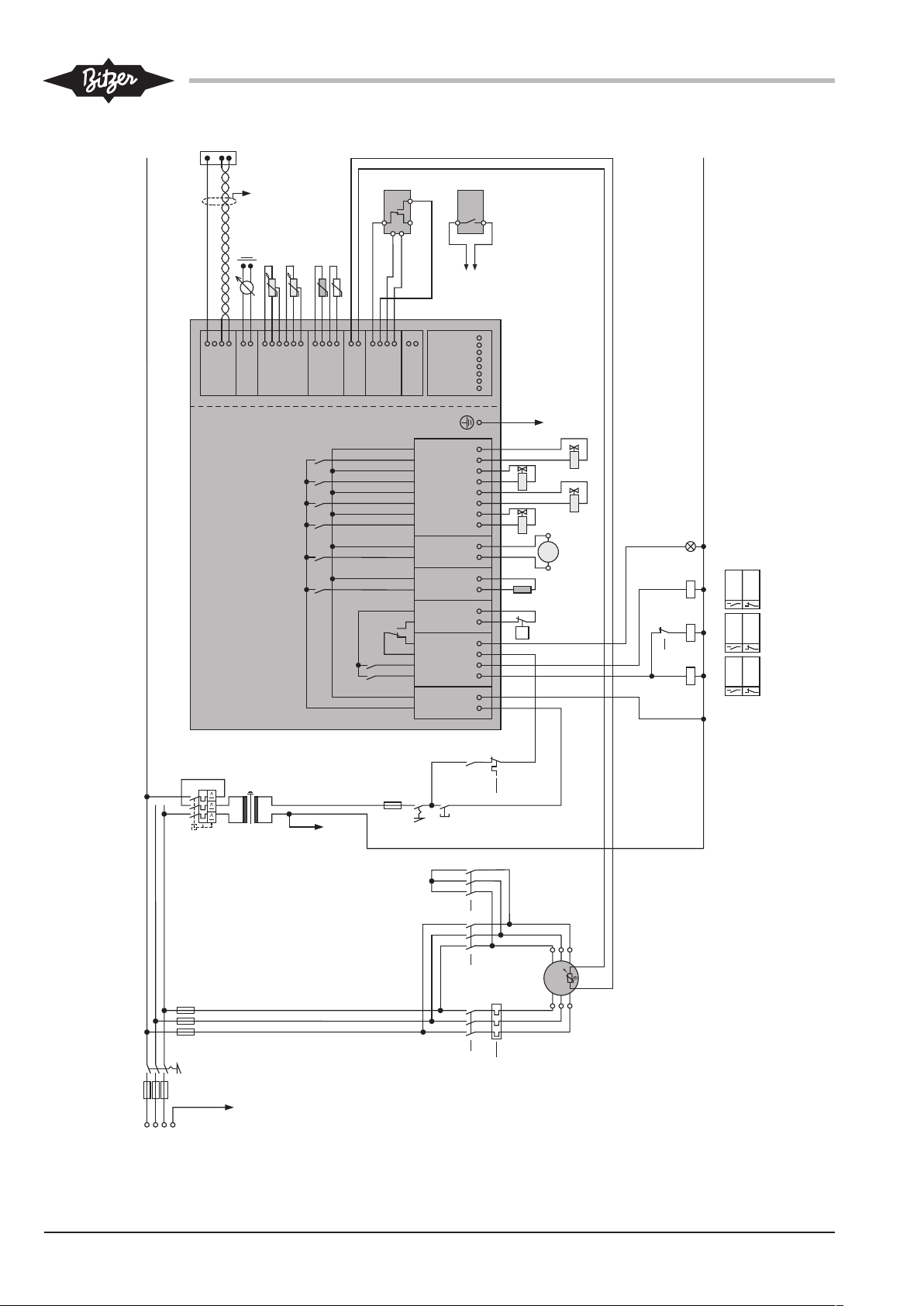
5.1 Schematic wiring diagram for part winding start ............................................................................................8
5.2 Schematic wiring diagram for star-delta start ................................................................................................8
5.3 Legend for the schematic wiring diagrams ....................................................................................................8
5.4 Motor start function ......................................................................................................................................11
5.5 Wiring in the state of delivery.......................................................................................................................11
5.6 High pressure switch ...................................................................................................................................11
6 Connecting cables ............................................................................................................................................... 11
6.1 Required electrical connections on the CM-RC-01......................................................................................12
6.2 Optional electrical connections ....................................................................................................................12
6.3 Controlling the CRII using the system controller..........................................................................................13
6.3.1 Control via analogue signal.............................................................................................................. 13
6.3.2 Control via Modbus interface ...........................................................................................................13
6.4 Connecting the operation monitoring device with the BEST Software ........................................................13
7 Protective functions .............................................................................................................................................13
8 Monitor the operating parameters using the BEST Software ..............................................................................14
8.1 Communication via the BEST Software.......................................................................................................14
8.2 Configuring CM-RC-01 with the BEST Software .........................................................................................15
8.2.1 Setting the current time.................................................................................................................... 15
8.2.2 Checking the motor start function ....................................................................................................15
8.2.3 Activating application limits monitoring ............................................................................................15
8.3 Data log .......................................................................................................................................................15
KT-230-12
Page 3
1 Introduction
Also observe the following technical documents
The CM-RC-01 compressor control module integrates
the entire electronic periphery of the compressor:
The CM-RC-01 monitors the essential operating parameters of the reciprocating compressor: motor and discharge gas temperature, oil supply and application limits. It protects the compressor from operation under critical conditions. The module provides virtually stepless
control of the compressor depending on the capacity
requirements of a superior system controller. It controls
the capacity regulators, the compressor cooling, the oil
heater and, if necessary, the start unloading and
provides the voltage supply of the associated components. Moreover, it controls the activation and deactivation of the motor contactors during the start. Additional
time relays are not required.
For delivery, the compressor control module can optionally be pre-installed on the reciprocating compressors 4VES-6Y to 8FE-70(Y). For this, several
equipment versions are possible.
During the operation, numerous operating data of the
compressor can be tracked using the BEST Software,
for example, the position in the application limits diagram. These data are recorded and allow the system
operation to be diagnosed. 4 coloured LEDs indicate
the operating condition of the compressor control module.
This Technical Information describes the control and
monitoring functions, the electrical connection of the
compressor control module and the communication
with the BEST Software.
Number Topic
KT-101 CRII: Capacity control
KT-110 Start unloading
KT-130 CIC system
KT-140 Additional cooling
KT-150 Oil heater
KT-170 Oil pressure monitoring
DT-300 OLC-D1: opto-electronic oil level monit-
oring
KG-230 Programming and control
2.1 Authorized staff
All work done on the compressors, the refrigeration
systems and their electronic accessories may only be
performed by qualified and authorized personnel who
have been trained and instructed accordingly. The local
regulations and guidelines will apply with respect to the
qualification and expertise of the specialists.
2.2 Residual risks
Compressors and electronic accessories may present
unavoidable residual risks. This is why any person
working on this device must carefully read this document!
The following regulations shall apply:
• the relevant safety regulations and standards (e.g.
EN378, EN60204 and EN60335),
2 Safety
Compressors and compressor control module have
been built in accordance with state-of-the-art methods
and current regulations. Particular importance was
placed on user safety.
The notes given in the Operating Instructions KB-104
must be followed in addition to this Technical Information.
Always keep the Operating Instructions KB-104 and
this Technical Information in the vicinity of the refrigeration system during the whole lifetime of the compressor!
• generally accepted safety rules,
• EU directives,
• national regulations.
2.3 Safety references
are instructions intended to prevent hazards. Safety references must be stringently observed!
NOTICE
Instructions on preventing possible damage to
equipment.
CAUTION
Instructions on preventing a possible minor hazard to persons.
WARNING
Instructions on preventing a possible severe
hazard to persons.
KT-230-1 3
Page 4
DANGER
Instructions on preventing an immediate risk of
severe hazard to persons.
2.3.1 General safety references
To be observed when performing work on the
compressor
WARNING
Risk of electric shock!
Before working on the terminal box, module
housing and electrical lines: Switch off the main
switch and secure it against being switched on
again!
Close the terminal box and the module housing
before switching on again!
WARNING
The compressor is under pressure!
Serious injuries are possible.
Depressurize the compressor!
Wear safety goggles!
When working on the electrical and/or electronic
system, please observe the following
NOTICE
The compressor control module may be damaged or fail!
Never apply any voltage to the terminals of CN7
to CN12 – not even for test purposes!
The voltage applied to the terminals of CN13
must not exceed 10V!
The voltage applied to terminal 3 of CN14 must
not exceed 24V! Do no apply voltage to the
other terminals!
3 Technical data
Compressor control module
Operating voltage 115..230V +10%/-15%, 50/60Hz, max. 600VA
Required fuse 4A time-lag at 230V / 8Atime-lag at 115V
Inputs, outputs and peripheral devices
Relay outputs for motor contactors
Terminal strip CN2
Maximum continuous current 2.5A
Switching voltage 250VAC
Maximum switching current 2.5A
Switching capacity 300VA inductive (NC contact: D300, NO contact:C300)
Voltage outputs for peripheral
devices
Terminal strip CN3: High pressure switch, CN4: Oil heater, CN5: Additional
fan, CN6: Solenoid valves
115..230V +10%/-15%, 50/60Hz, according to the selected operating
voltage of the CM-RC-01. Select the peripheral devices accordingly!
Optional temperature sensor
(R11)
Terminal strip CN11
The connection is suitable for a PT1000 sensor with a measuring range
between -40°C..100°C
Analogue signal used for capacity control
Terminal strip CN13
0..10VDC, ±2% at 100%
at max. 1mA
Modbus connection Terminal strip CN14
Modbus RTU, RS485
Connection cable
Connection cable for power
connections
Terminal strips CN1 to CN6
The terminals are suitable for max. 2.5mm2 (AWG12)
KT-230-14
Page 5

Select the cable cross-sections in accordance with the local regulations!
Use copper cables with a sheath quality suitable for at least 85°C. Select the
cable quality according to the installation location, e.g. UV- and/or oil-resistant.
Connection cable for control
and sensor signals
Terminal strips CN7 to CN14
The terminals are suitable for max. 1.5mm2 (AWG16)
Select the cable cross-sections in accordance with the local regulations!
Use copper cables with a sheath quality suitable for at least 85°C. Select the
cable quality according to the installation location, e.g. UV- and/or oil-resistant.
Available cable bushings in the
module housing
For standard version: 2 x M25, 2 x M20, 1 x M16, each with screwed joints
For equipment versions A and B: 1 x M25, 2 x M20, 1 x M16, each with
screwed joints
Characteristics of the compressor control module
Enclosure class Module housing in its state of delivery:
IP65 for 4VES-6Y..6FE-50(Y), IP54 for 8GE-50(Y)..8FE-70(Y)
Control module without module housing: IP00
Internal fuse Terminal strips CN4 to CN6
This overcurrent fuse protects the CM-RC-01, if a short circuit occurs in one of
the connected components: oil heater, additional fan or in a solenoid valve.
A warning is output in the BEST Software or via Modbus.
Place of installation Allowable ambient temperature: -30°C..+70°C
Allowable relative humidity: 5%..95% (EN60721-3-3 Classes 3K3 and 3C3)
Maximum allowable altitude: 2000m
EMC The control module complies with the EMC directives 2014/30/EU and
2004/108/EC
Interference immunity
EN61000-6-1:2007, Immunity for residential, commercial and light-industrial
environments
EN61000-6-2:2005, Immunity for industrial environments
Emitted interference
EN61000-6-3:2007 +A1:2011, Emission standard for residential, commercial
and light-industrial environments.
The control module internally supplies the voltage to
peripheral devices (solenoid valves, additional fan, oil
monitoring and oil heater) and to the terminal strips
CN7 to CN12.
3.1 Equipment versions
For delivery, the compressor control module can optionally be pre-installed in the reciprocating compressors 4VES-6Y to 8FE-70(Y). Several versions and
extensions are possible.
Standard state of delivery
In the table, the standard state of delivery is marked as
"standard". These components are completely mounted
and electrically connected.
KT-230-1 5
Page 6
Equipment versions A and B
430
63
382
63
716
162
187
A
B
C
D
CRII-2 1 2 CRII-1/SU
Option Option
3
OLC-D14
Extensions
These equipment versions are provided, in addition to
the standard state of delivery, with further components
which are completely mounted and electrically connected. In the table, these functions are marked with "A" or
The components which can be retrofitted are marked in
the table as "options". They are delivered as accessories kit and must be mounted, wired and activated via
the BEST Software.
"B".
4VES-6Y..4N
ES-20(Y)
4JE-13Y..4FE
-35(Y)
6JE-22Y..6FE
-50(Y)
8GE-50(Y)..8
FE-70(Y)
Motor temperature monitoring (R1..R6) Standard Standard Standard Standard
Discharge gas temperature sensor (R7) Standard Standard Standard Standard
Oil monitoring (F4) Standard:
OLC-D1: optoelectronic oil
level monitor-
Standard:
DP-1: differential oil pressure
monitoring
Standard:
DP-1: differential oil pressure
monitoring
Standard:
DP-1: differen-
tial oil pressure
monitoring
ing
2 capacity regulators (Y3-1 and Y3-2) A: CRII-1 and
CRII-2
A: CRII-1 and
CRII-2
A: CRII-1 and
CRII-2
A: CRII-1 and
CRII-2
Start unloading (Y1) B: SU B: SU B: SU
Capacity regulator (Y3-2) B: CRII-2 B: CRII-2 B: CRII-2
3rd capacity regulator (Y3-3) Option: CRII-3
Monitoring of application limits: High pres-
Option Option Option Option
sure transmitter (B6) and low pressure
transmitter (B7)
Additional fan (M2) Option Option Option
CIC additional cooling (Y5) Option Option Option
Optional temperature sensor (R11) Option Option Option Option
Tab.1: CM-RC-01: pre-assembled variants and possible extensions
Information
Upon market launch, not all components are
available for each connection voltage. This is
also valid for the CIC system and the equipment
version B. The CM-RC-01, however, is able to
control the start unloading. Information regarding retrofitting available upon request.
3.2 Dimensional drawings
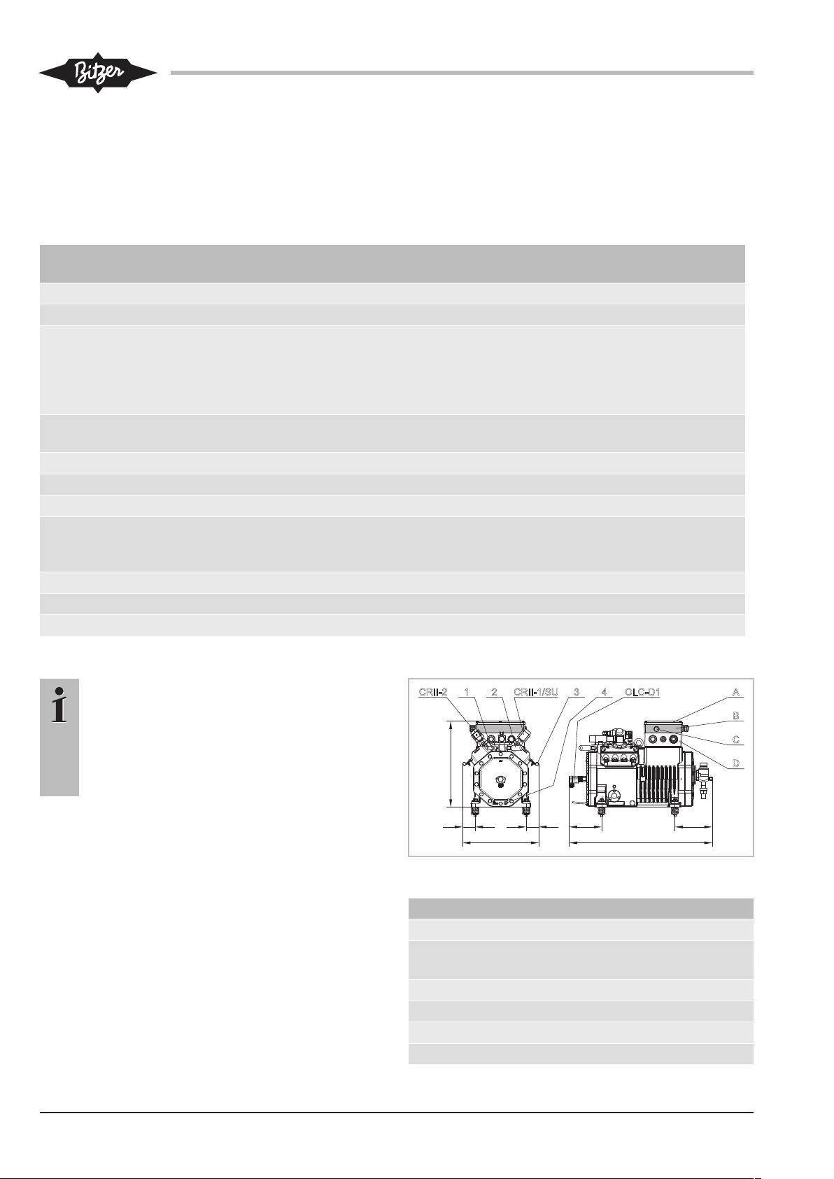
These dimensional drawings show the equipment versions "A" and "B". The pre-assembled options and possible extensions differ depending on the compressor
series, see chapter Equipment versions, page 5.
CM-RC-01 in 4VES-6Y .. 4NES-20(Y)
Fig.1: 4VES-6Y .. 4NES-20(Y) with CM-RC-01
Connection positions
1 Discharge gas temperature sensor
2 Connection position for high pressure
switch
3 Cable holder
4 Oil heater
A Cover for terminal box
B Module housing (grey)
KT-230-16
Page 7

Connection positions
D LED sight glass
D Terminal box
Dimensional drawings for 4JE-13Y..8FE-70(Y) upon
request.
Upon market launch, a high pressure switch with a cutout pressure of 32bar is mounted at position 2 and
electrically connected to the CM-RC-01. For the compressors 4VES-6Y to 4NES-20(Y), a high pressure limiter is used. For all other compressors, a high pressure
cut-out is used.
4 Control and monitoring functions
The module activates the additional fan in the lower
part-load range to cool down the motor, if necessary.
This is done for 4-cylinder compressors in a part-load
range below 50% and for 6-cylinder compressors below
33%.
Oil heater
When the compressor is at standstill, the module
switches the oil heater on and if the compressor is in
operation, the oil heater is switched off.
Control of the motor contactors at compressor start
The compressor control module controls the activation
and deactivation times of the motor contactors. In the
state of delivery, the time relay control is configured for
the installed motor:
4.1 Control functions
This chapter describes all control functions including
the options.
Capacity control CRII
The CM-RC-01 provides virtually stepless adjustment
of the compressor capacity depending on the setpoint
of the superior system controller. This is done by
switching the CRII solenoid valves. 4-cylinder compressors with 2 and 6-cylinder compressors with 3 installed capacity regulators are regulated between full
load and 10% part load, 8-cylinder compressors
between full load and 50%.
If a start unloading is mounted, there is one cylinder
bank less available for the capacity control. The range
of control for the capacity control is reduced accordingly.
Start unloading SU
The start unloading can be installed for 4 and 6-cylinder
compressors. The module controls the solenoid valve
and ensures an unloaded compressor start.
Compressor cooling
The compressor control module activates the additional
fan when the discharge gas temperature of 120°C is
exceeded and deactivates it as soon as a temperature
of 100°C is reached. If the discharge gas temperature
reaches 135°C, the CIC is activated intermittently, from
a temperature of 140°C, it works permanently. While
the CIC is active, the compressor can only be operated
in the upper part-load range. The limit is 50% for 4-cylinder compressors and 66% for 6-cylinder compressors.
Part winding motor: The contact at CN2:2 (K1 Control)
closes 1second after the release signal. The contact at
CN2:1 (K2 Control) closes 0.5seconds afterwards.
Both contacts remain closed until the compressor is
shut off.
Star-delta motor: The contact at terminal CN2:2 (K1
Control) closes 1second after the release signal and
reopens after further 1.5seconds. The contact at terminal CN2:1 (K2 Control) closes 1.5seconds after the
release signal and remains closed until the compressor
is shut off.
Motor for direct-on-line start: The contact at terminal
CN2:2 (K1 Control) closes 1second after the release
signal and reopens when the compressor is shut off.
The contact at terminal CN2:1 (K2 Control) is not used.
For a soft start and operation with frequency inverter,
only one motor contactor is required.
4.2 Monitoring and protective functions
The compressor control module monitors the signals
from several sensors that may be located on the compressor or on the suction gas and discharge gas line:
Monitored function Measuring sensor
Motor temperature
(standard)
Discharge gas temper-
ature (standard)
Application limits (op-
tion):
Condensing and evaporation temperature
Low pressure (option) Low pressure transmitter
Motor temperature sensor
(R1..R6)
Discharge gas temperature
sensor (R7)
Low pressure and high
pressure transmitters (B7
and B6)
(B7)
KT-230-1 7
Page 8

Monitored function Measuring sensor
High pressure (option) High pressure transmitter
(B6)
Oil supply (standard) Oil level monitoring with
OLC-D1 (F4) on 4VES-6Y
to 4NES-20(Y)
Differential oil pressure
monitoring with DP-1 (F4)
on 4JE-13Y to 8FE-70(Y)
Cycling rate of the
Integrated in CM-RC-01
compressor (standard)
Temperature at any
place (option)
Optional temperature
sensor
The compressor control module compares the measured values with the the programmed data, sending
signals via Modbus and indicating the operating condition by means of differently coloured LEDs, see chapter
Protective functions, page 13. The compressor will be
shut off in case of operation beyond the application limits, lack of oil or excessive motor temperature. The cycling rate and the measured value of the optional temperature sensor are monitored and recorded.
5 Electrical connection
Keep the compressor control module energized when
the motor is not running. If necessary, the module activates the oil heater, thus ensuring the lubricity of the oil
even after a long standstill period.
De-energize the module only if you plan a long standstill period of the compressor or for maintenance purposes.
5.1 Schematic wiring diagram for part winding start
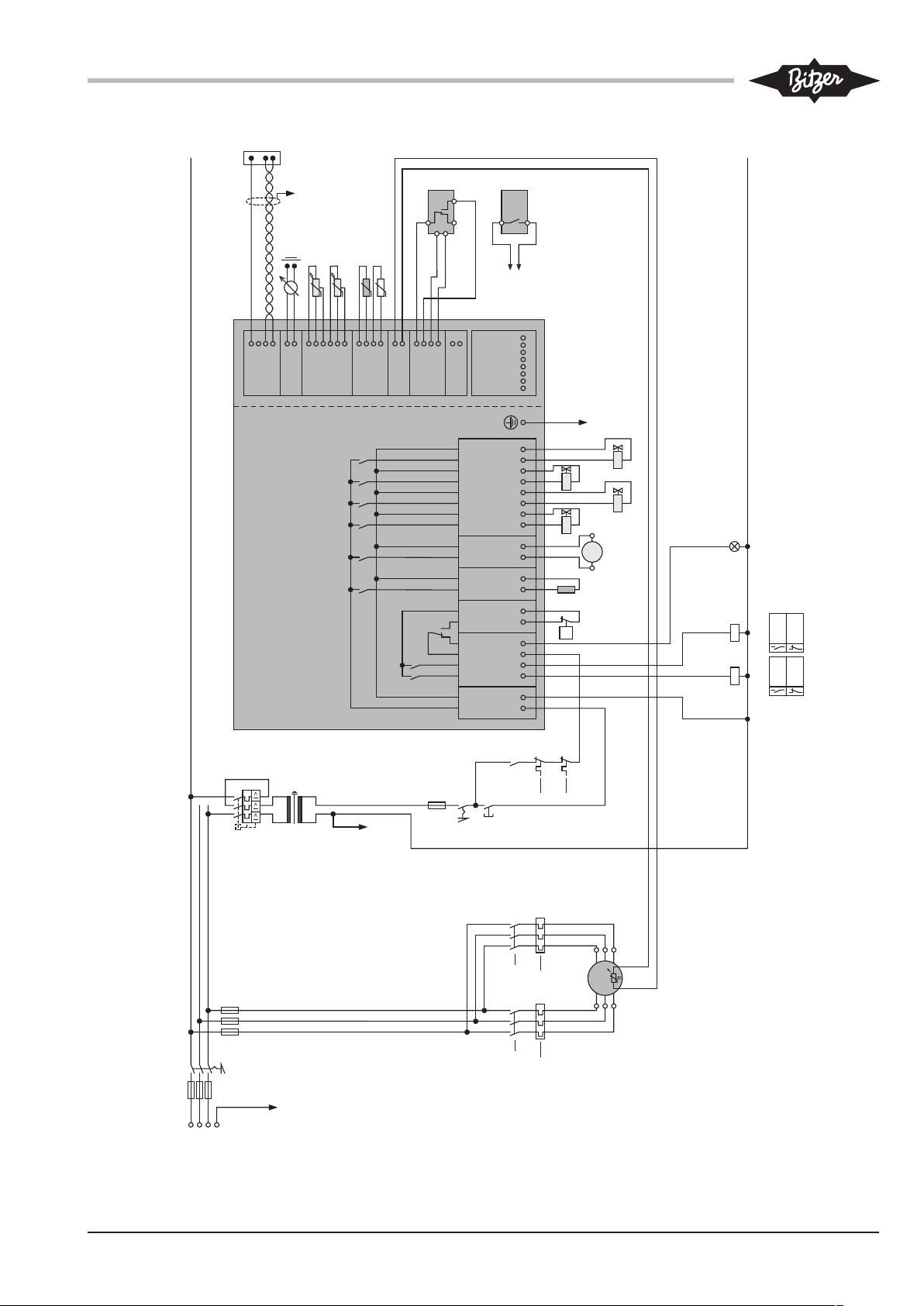
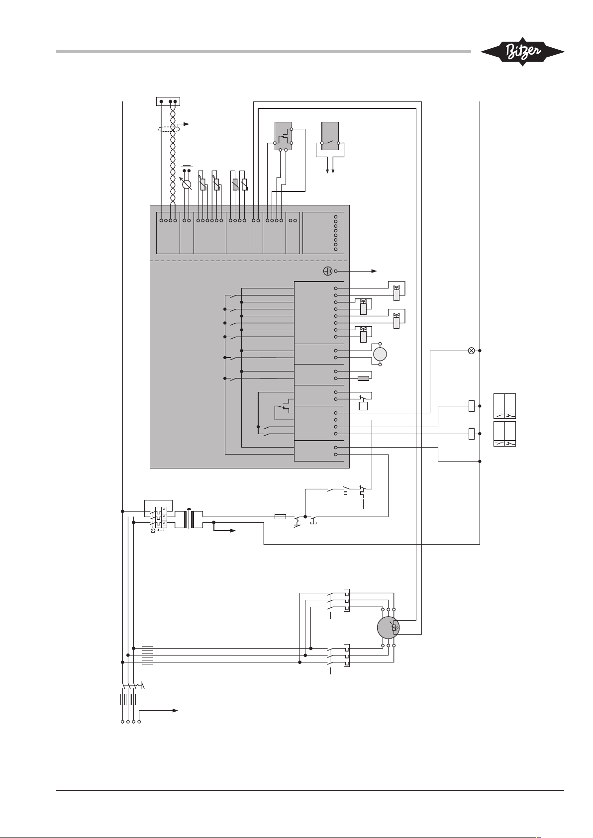
Schematic wiring diagram, see figure 2, page 9. In
the event of direct start, path 4 is omitted: contactor K2
and thermal overload relay F14 as well as the cable
connection on the terminal strip CN2, terminal 1. For
soft start and operation with frequency inverter, only
one contactor is required.
For operation with frequency inverter, please observe
the following: Emit the release signal to the compressor
control module only after charging of the DC link during
the first switch-on.
5.3 Legend for the schematic wiring diagrams
Abbr. Component
B1 Command for compressor start (release sig-
nal from system controller)
B6 High pressure transmitter
B7 Low pressure transmitter
F1 Main fuse
F2 Compressor fuse
F3 Control circuit fuse
F4 Oil monitoring: 4VES-6Y..4NES-20(Y): OLC-
D1 / 4JE-13Y..8FE-80(Y): DP-1
F5 High pressure switch
F13 Thermal overload relay "Motor" (1st part wind-
ing and Y/Δ)
F14 Thermal overload relay "Motor" (2nd part
winding)
F17 Control transformer fuse
H3 Signal lamp "Collective fault"
K1 Contactor "1st part winding" (PW) or main
contactor (Y/Δ)
K2 Contactor "2nd part winding" (PW) or delta
contactor (Y/Δ)
K3 Star contactor (Y/Δ)
M1 Compressor
M2 Additional fan
Q1 Main switch
R1..6PTC sensor in motor winding
R7 Discharge gas temperature sensor
R8 Oil heater
R11 Optional temperature sensor (not included in
the scope of delivery)
S1 Control switch (on/off)
S2 Fault reset of CM-RC-01
T1 Control transformer (example for 230V)
Y1 Solenoid valve "Start unloading SU"
Y3-1 Solenoid valve "1st capacity regulator CRII"
Y3-2 Solenoid valve "2nd capacity regulator CRII"
Y3-3 Solenoid valve "3rd capacity regulator
CRII" (only for BE6 compressors)
Y5 CIC injection valve
5.2 Schematic wiring diagram for star-delta start
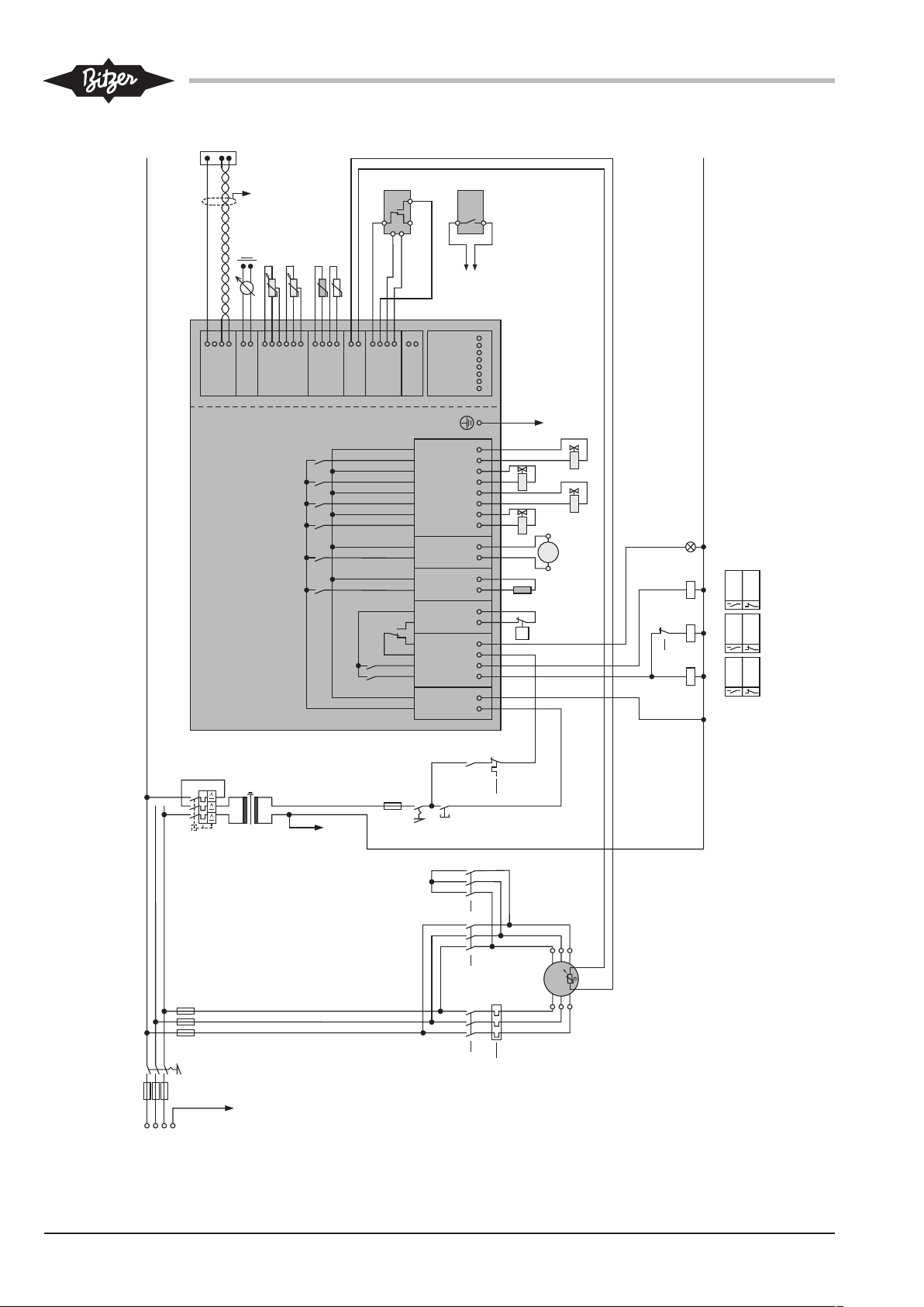
In the event of star-delta start, the motor contactors are
not connected according to the terminal labelling on the
CM-RC-01, see figure 3, page 10.
Tab.2: Components of the schematic wiring diagrams
KT-230-18
Page 9
1 2 3 4
CN1
L N
CN2
K2control
Supply
Supply
K1control
RelayC
RelayNC
CN3
HPS
HPS
CN4
Heater
Heater
CN5
Add. fan
Add. fan
CN6
CR-1
CR-1
CR-2
CR-2
CR-3
CR-3
Injection
Injection
5 6 7 8
CN7
1 2 3 4 1 2
CN9
CN10
1 2 3 4 5 6
CN12
1 2 3 4
CN11
1 2
CN13
1 2 3 4
CN14
24VSup
GND
Signal
GND
PTC
PTC
Signal
GND
Signal
GND
5VSup
Signal
GND
5VSup
Signal
GND
Input
GND
Data+
Data–
Sup In
GND
24VSup
GND
Signal
GND
21 3 4 1 2 1 N 1 N 1 N 3 N 5 N 7 N
CM-RC-01
4321 876
5
13
1211
109
14
15
16
17
18 19 20
21 22
S2
F2
L1L2L3
PE
F1
Q1
1
0
K1
11
K2
10
M 3~
F13
8
F17
230V
T1
F3 4A T
PE
S1
01
F13
2
B1
H3
W1
V1
U1
V2
U2
W2
M1
K2
Y3-2
Y5
4/4/4
grau/grey
braun/brown
orangerosa
pink
blau/blue
B6
B7
Modbus
RS485
PE
0 .. 10V
R7
PE
F5
P>
R8
M2
Y3-1
1 2
CT
CT
CN8
R11
132
1
3
2
R1..6
F14
4
F14
8
2/2/2
K1
(2CP5-71-49)
(2CP5-71-47)
F4
F4
OLC-D1
DP-1
CN9:3
CN9:4
Y3-3
M
1~
Fig.2: Schematic wiring diagram for part winding start
KT-230-1 9
Page 10
1 2 3 4
CN1
L N
CN2
K2control
Supply
Supply
K1control
RelayC
RelayNC
CN3
HPS
HPS
CN4
Heater
Heater
CN5
Add. fan
Add. fan
CN6
CR-1
CR-1
CR-2
CR-2
CR-3
CR-3
Injection
Injection
5 6 7 8
CN7
1 2 3 4 1 2
CN9
CN10
1 2 3 4 5 6
CN12
1 2 3 4
CN11
1 2
CN13
1 2 3 4
CN14
24VSup
GND
Signal
GND
PTC
PTC
Signal
GND
Signal
GND
5VSup
Signal
GND
5VSup
Signal
GND
Input
GND
Data+
Data–
Sup In
GND
24VSup
GND
Signal
GND
21 3 4 1 2 1 N 1 N 1 N 3 N 5 N 7 N
CM-RC-01
4321 876
5
13
1211
109
14
15
16
17
18 19 20
21 22
S2
F2
L1L2L3
PE
F1
Q1
1
0
K1
10
K2
11
M 3~
F13
8
K3
12
F17
F3 4A T
PE
S1
01
F13
2
B1
H3
W1
V1
U1
V2
U2
W2
M1
2/2/2
K1
K2
K3
12
Y3-2
Y5
4/4/4
grau/grey
braun/brown
orangerosa
pink
blau/blue
F4
B6
B7
Modbus
RS485
PE
0 .. 10V
5/5/5K311
R7
PE
R8
M2
Y3-1
1 2
CT
CT
CN8
R11
132
1
3
2
R1..6
F5
P>
F4
Y3-3
(2CP5-71-49)
(2CP5-71-47)
OLC-D1
DP-1
CN9:3
CN9:4
230V
T1
M
1~
Fig.3: Schematic wiring diagrams for star-delta start
KT-230-110
Page 11
5.4 Motor start function
6 Connecting cables
The compressor control module controls the activation
and deactivation times of the motor contactors. In the
state of delivery, the time relay control is configured for
the installed motor.
5.5 Wiring in the state of delivery
The following components are pre-installed and wired
in the state of delivery:
• Oil heater (standard, R8)
• Oil monitoring (standard, F4)
• Discharge gas temperature sensor (standard, R7)
• additionally for equipment version A: 2 solenoid
valves for capacity control (Y3-1 and Y3-2)
• additionally for equipment version B: 1 solenoid
valve for start unloading (Y1) and 1 solenoid valve
for capacity control (Y3-2)
• and additionally during the market launch phase:
High pressure switch (standard, F5)
These components are shown in a slightly darker grey
in the schematic wiring diagram. Modification to these
components or their wiring is not required and should
not be done without consulting BITZER.
All other optional components are shown in light grey.
They are delivered as accessories kit and must be
mounted and wired.
Electrically connect the compressor control module in
accordance with the schematic wiring diagram. Observe the safety standards EN60204, EN60364 and
national safety regulations.
WARNING
Risk of electric shock!
Before working on the terminal box, module
housing and electrical lines: Switch off the main
switch and secure it against being switched on
again!
Close the terminal box and the module housing
before switching on again!
NOTICE
The compressor control module may be damaged or fail!
Never apply any voltage to the terminals of CN7
to CN12 – not even for test purposes!
The voltage applied to the terminals of CN13
must not exceed 10V!
The voltage applied to terminal 3 of CN14 must
not exceed 24V! Do no apply voltage to the
other terminals!
The CM-RC-01 is installed directly above the terminal
box for the power connection of the compressor. For
the 8-cylinder compressors, it is located in the terminal
box.
Compressor power connection
5.6 High pressure switch
According to the EN 378, each compressor must be
provided with a high pressure switch (F5) for safety cutout in the safety chain. This switch can be mounted directly to the compressor and integrated into the electrical safety chain via the CM-RC-01. Mounting position
see chapter Dimensional drawings, page 6, connect the
cables directly to the terminal strip CN3 according to
the schematic wiring diagram.
If optional application limits monitoring is installed, the
installation of a low pressure switch is not necessary
because the automatic low pressure cut-out function of
the compressor control module is active.
• Remove the module housing cover.
• The module housings of the 4-cylinder and 6-cylinder compressors are screwed to the terminal box for
the power connection of the compressor. Remove
the module housing. Make sure that the two orange
cables and the protective earth conductor are not
damaged and that the connections do not become
detached. The orange cables are the motor temperature sensor cables.
• Connect the power connection cable for the compressor motor according to the label on the lower
part of the module housing and the Operating Instructions KB-104. The label for 8-cylinder compressors is located on the inside of the terminal box
cover.
• Both orange cables and protective earth conductor:
Check the cables. Check the cable connections on
the terminal plate for tight seat.
• Re-attach the module housing on 4-cylinder and 6cylinder compressors.
KT-230-1 11
Page 12
6.1 Required electrical connections on the CM-RC-01
• Module power connection on terminal strip CN1
(115 .. 230V +10%/-15%, 50/60Hz)
– Terminal 1: L
– Terminal 2: N
• Command for compressor start (release signal from
the system controller, B1)
The release signal from the system controller is
provided in path 8 as the first link of the safety chain.
This release information must be passed on to the
compressor control module. It activates the time relay control for the motor contactors K1, K2 and K3.
– Connect the safety chain (release signal) to ter-
minal strip CN2, terminal 3.
– Integrate the compressor control module as the
last link into the safety chain.
– Connect the contactors directly to terminal strip
CN2 according to the schematic wiring diagram.
Length of the refrigerant hose: at least 200mm to avoid
dew formation on the transmitter.
Electrical connection: Connect the cables at the CMRC-01 directly to terminal strip CN12 according to the
schematic wiring diagram.
Additional fan
Mount the fan feet to the cylinder heads. Please refer to
the Technical Information KT-140.
Connect the cable of the additional fan to the CMRC-01 to terminal strip CN5 according to the schematic
wiring diagram.
CIC system
WARNING
The compressor is under pressure!
Serious injuries are possible.
Depressurize the compressor!
Wear safety goggles!
• Control signal from the system controller (setpoint for
capacity control, CRII)
This connection is only required if the compressor is
equipped with capacity regulators.
– Connect the Modbus cable to terminal strip CN14.
– Or connect the analogue signal to terminal strip
CN13.
• Close the module housing:
– Check if the cable connections of the protective
earth conductors are tight.
– Re-attach the module housing cover and screw it
down.
6.2 Optional electrical connections
Monitoring of application limits
High pressure and low pressure transmitters B6 and B7
are delivered as accessories kit if the "Application limits
monitoring" option has been ordered. They must be
mounted to the system, wired with the CM-RC-01 and
activated via the BEST Software. The two transmitters
must not be interchanged. They differ by the component number engraved in the component:
• High pressure transmitter B6: 2CP5-71-47
Mounting: Connect the injection nozzle to the CIC connection. This position is described in the Operating Instructions of the compressor KB-104 (dimensional
drawings: connection position 4). With 6-cylinder compressors, 2 nozzles are mounted.
• Remove the plug from the compressor.
• Clean and check the threaded bore.
• Mount the gasket and the injection nozzle according
to KT-130, chapter 5.4 "Injection nozzle and injection
valve".
• Press the solenoid coil onto the armature. It locks.
• Insert the electric connector of the device and screw
it down (5Nm).
• Connect the cables of the CM-RC-01 to terminal
strip CN6, terminals 7 and 8, according to the
schematic wiring diagram.
Third capacity regulator Y3-3
For 6-cylinder compressors, a third capacity regulator
can be activated. The CRII cylinder head required for
this is mounted in the state of delivery if the compressor has been ordered accordingly. It can also be
retrofitted. Further information on the mounting of the
solenoid valve and the CRII cylinder head can be found
in the Technical Information KT-101.
• Low pressure transmitter B7: 2CP5-71-49
Mounting position: Connect them to the discharge gas
line and/or the suction gas line, as close as possible to
the valves using a refrigerant hose for each valve.
Electrical connection: Connect the cables of the CMRC-01 to terminal strip CN6, terminals 5 and 6, according to the schematic wiring diagram.
KT-230-112
Page 13
Optional temperature sensor R11
CRII
0 2 4 6 8 10 12
U [V]
0 .. 10 V
min
min
1
80%
60%
40%
20%
0%
0,2
*
An optional PT1000 temperature sensor can be connected to the control. The data of the temperature
sensor are logged but they do not influence the control
and the monitoring.
Electrical connection: Connect the cables of the CMRC-01 to terminal strip CN11, terminals 1 and 2, according to the schematic wiring diagram.
The BEST Software detects this sensor automatically.
6.3 Controlling the CRII using the system controller
CRII can be controlled via Modbus or an analogue signal. Compressor operation at reduced capacity is only
admissible within the part-load limits for the respective
refrigerant. Minimum residual capacity: 10%. Program
the system controller accordingly. Application limits,
see BITZER Software and Technical Information
KT-101.
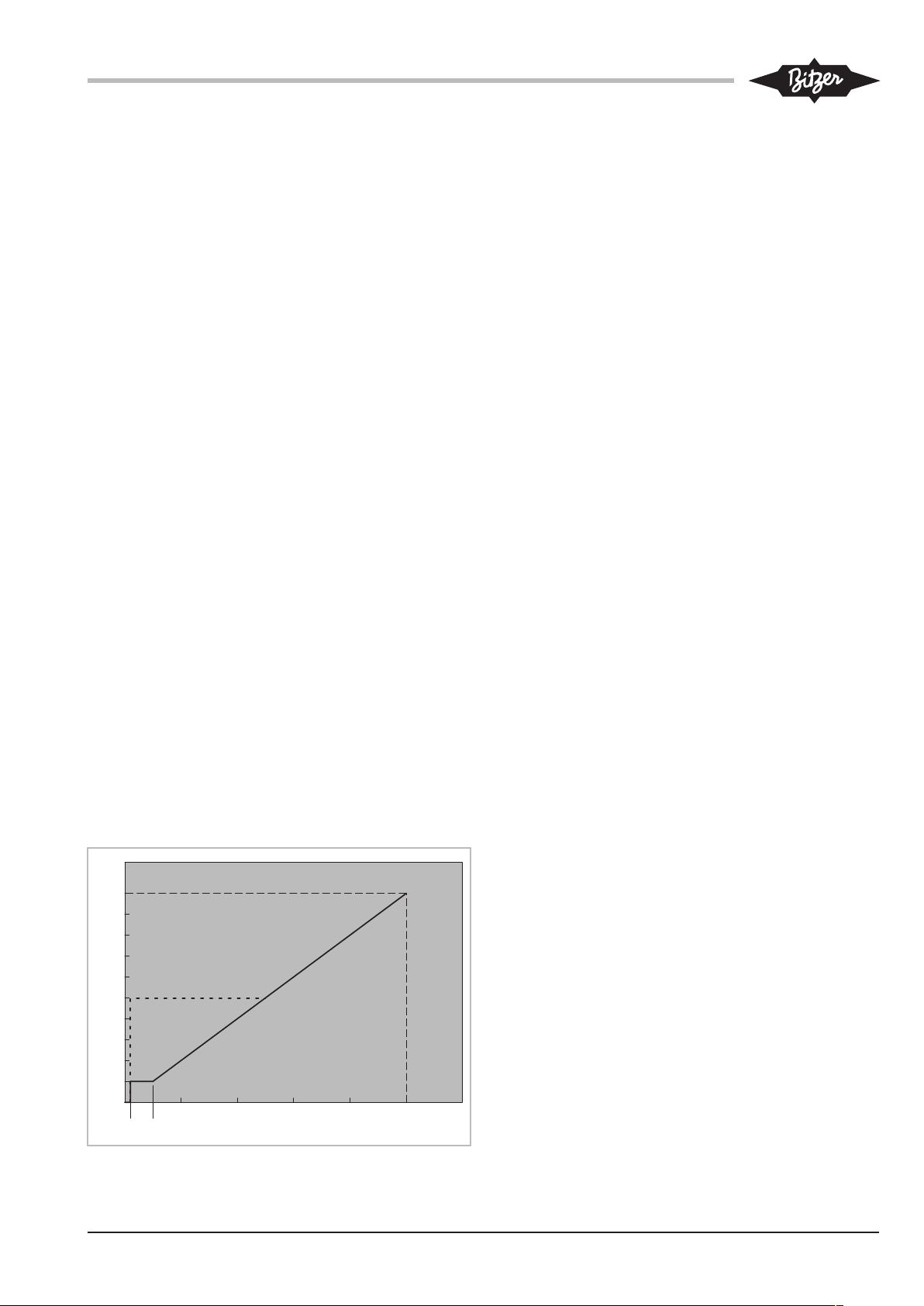
6.3.1 Control via analogue signal
The compressor capacity is regulated via a DC voltage
signal. This type of control is mainly suitable for systems with simple controllers which are equipped with
an output for 0 to 10V and a relay, and for use in combination with the BEST Software on Modbus connection.
• Connection to terminal strip CN13, terminals 1 and
2.
• CR
: The compressor capacity can be reduced
min
from 100% to 10% if each cylinder head is equipped
with CRII capacity regulators.
• CR
* and dashed line: The range of control is re-
min
duced if not every cylinder bank is equipped with capacity regulators. The minimum capacity step of 50%
is the lower regulation limit for 8-cylinder compressors and for 4-cylinder compressors with one
capacity regulator. In this case, the CM-RC-01 regulates to a residual capacity of 50% as soon as the
control signal falls below 5V.
6.3.2 Control via Modbus interface
Insert or connect the cable to terminal strip CN14. See
schematic wiring diagrams.
In this case, the operating parameters can be monitored via Bluetooth by means of the BEST Software.
6.4 Connecting the operation monitoring device with the BEST Software
• Connect the BEST interface converter to terminal
strip CN14 (Modbus).
In this case, the capacity control must be predefined via
the analogue signal on terminal strip CN13.
The BEST Software can access the compressor control
module via a Bluetooth interface, see chapter Communication via the BEST Software, page 14. This interface is not available upon market launch.
• Control signal: 0 to 10V direct current voltage for an
analogue output of the system controller
• Control accuracy: ±0.5% at 100%
• Linear control characteristic, see figure.
7 Protective functions
The green LED is on during normal operation. The
LEDs can be seen through a sight glass in the module
housing, see chapter Dimensional drawings, page 6.
Before the measured value of a sensor reaches a critical threshold, the compressor control module outputs a
warning signal via the Modbus RS485 interface
(CN14). In this case, the yellow LED lights up. Once a
measured value is considerably outside the allowable
range, the compressor control module will immediately
switch off the motor. The red LED lights up.
The blue LED lights up when data are transmitted via
the Modbus interface.
Depending on the measured parameter, up to 3 alarm
levels are defined. These alarms are recorded and displayed using the BEST Software. The alarm levels
make it possible to programme a system controller in a
way that allows the compressor to be adjusted within
Fig.4: Control characteristic
the application limits.
KT-230-1 13
Page 14
Warning
The warning threshold is exceeded when the application limit is almost reached. The yellow LED lights up.
This is a software message, not a safety reference. The
warning refers exclusively to the critical operating condition of the compressor.
The cut-out value is exceeded. The yellow LED lights
up. If the corresponding measured value does not drop
again within 30 seconds, the compressor will be
switched off. This cut-out is classified as fault in the
alarm list.
Fault
Critical alarm
Monitored function Time delay after
compressor start
Discharge gas temperature --- >135°C --- >150°C
Oil supply 90s 5s --- locks out after
Cycling rate of the compressor
Application limits, option
(Condensing temperature,
evaporation temperature)
Low pressure, option --- --- --- <0.2bar / < relat-
High pressure, option --- --- --- >32 bar / >relat-
--- > 8 compressor
120s <2K within the
The cut-out value has been exceeded too much or for
too long. The compressor is switched off. The red LED
lights up.
Warning Critical alarm Fault
locks out after
20s
90s
--- --cut-outs within one
hour
application limits
>2K outside the
application limits
locks out after
30s
>4K outside the
application limits
locks out immediately
ive pressure
entered in BEST
Software: locks
out immediately
ive pressure
entered in BEST
Software:
Reset
Disconnect the voltage supply (L/N) for at least 5
seconds, via Modbus command or reset alarms with
the BEST Software by pressing the RESET button in the
ALARMS menu.
8 Monitor the operating parameters using the BEST
Software
The BEST Software displays all active alarms and the
following operating parameters:
• Capacity control level
locks out immediately
• Condensing temperature
• Evaporation temperature
• Low pressure
• High pressure
• Discharge gas temperature
8.1 Communication via the BEST Software
Requirements:
• Mobile device
– equipped with the operating system Windows XP
or newer
KT-230-114
Page 15

– with USB port or Bluetooth
8.2.2 Checking the motor start function
– with BEST Software installed
The BEST Software can be downloaded for free
from the BITZER website (www.bitzer.de).
• Data connection
– via BEST interface converter
– or via Bluetooth 4.0. Range approx. 3m
• If the BEST interface converter is used, the compressor must be controlled via the analogue connection (CN13). The Modbus connection does not allow
capacity control and BEST data connection at the
same time. Bluetooth is not available upon market
launch.
Setting up communication
• Only for communication via the BEST interface converter: Plug the cable into the compressor control
module (CN14) and the mobile device.
• Switch on the mobile device and start the BEST
Software.
A window displaying the available devices opens.
The compressor control module controls the activation
and deactivation times of the motor contactors. In the
state of delivery, the time relay control is configured for
the installed motor. The BEST Software can be used to
check and change the configured motor start method
(part winding, star-delta or direct-on-line start).
Check in the BEST Software and adapt if necessary:
• CONFIGURATION menu, MOTOR STARTER FUNCTION window. When operating with frequency inverter or soft
starter, the system must be set to direct-on-line start.
If necessary, set the suitable motor start function.
In any case, the compressor motor is activated
1second after the release signal of the superior system
controller.
8.2.3 Activating application limits monitoring
◦ Requirements: High pressure and low pressure
transmitters are installed.
• Set the refrigerant in the BEST Software: select the
refrigerant used in the REFRIGERANT window in the
MAIN SETUP menu.
• Select CM-RC-01.
• Click the CONNECT button.
• Only for communication via Bluetooth: Enter the authorization code.
The CONFIGURATION menu appears with the MAIN SETUP
window. This concludes the connection of the compressor control module to the mobile device.
8.2 Configuring CM-RC-01 with the BEST Software
In its state of delivery, the compressor control module
CM-RC-01 is configured for the compressor, in which it
is built in, and its motor. Date and time should be
checked and adjusted if necessary. Afterwards, a configuration of the installed options is required. Depending on the system design, it may be useful to adjust
some other parameters.
8.2.1 Setting the current time
Check the programmed date and time using the BEST
Software:
• Check the CONFIGURATION menu, the MAIN SETUP window and the DATE and TIME lines.
• Enter relative pressure limit values that are adapted
to the system in the CONFIGURATION menu, PROTECTIVE
FUNCTIONS window, in the lines HIGH PRESSURE SWITCH:
VALUE and LOW PRESSURE SWITCH: VALUE. Basic setting: 32bar / 0.2bar, relative pressures. The high
pressure cannot be further increased.
8.3 Data log
All monitored operating parameters and alarm messages are stored internally:
• All operating parameters in 10-second intervals of at
least the last 14 days
• The last 10 faults in detail
• Statistics for the last 365 days
The data can be exported as files using the BEST Software. They enable an analysis of the system operation
and detailed error diagnostics if necessary.
• Correct the data if necessary.
KT-230-1 15
Page 16

Inhaltsverzeichnis
1 Einleitung.............................................................................................................................................................17
2 Sicherheit.............................................................................................................................................................17
2.1 Autoriertes Fachpersonal.............................................................................................................................17
2.2 Restgefahren ...............................................................................................................................................17
2.3 Sicherheitshinweise .....................................................................................................................................17
2.3.1 Allgemeine Sicherheitshinweise ...................................................................................................... 18
3 Technische Daten................................................................................................................................................18
3.1 Ausstattungsvarianten .................................................................................................................................19
3.2 Maßzeichnungen .........................................................................................................................................20
4 Steuer- und Überwachungsfunktionen ................................................................................................................21
4.1 Steuerfunktionen..........................................................................................................................................21
4.2 Überwachungs- und Schutzfunktionen ........................................................................................................21
5 Elektrischer Anschluss ........................................................................................................................................22
5.1 Prinzipschaltbild für Teilwicklungsanlauf .....................................................................................................22
5.2 Prinzipschaltbild für Stern-Dreieck-Anlauf ...................................................................................................22
5.3 Legende zu den Prinzipschaltbildern...........................................................................................................22
5.4 Motoranlauffunktion .....................................................................................................................................24
5.5 Verkabelung im Auslieferungszustand ........................................................................................................25
5.6 Hochdruckschalter .......................................................................................................................................25
6 Kabel anschließen ............................................................................................................................................... 25
6.1 Erforderliche elektrische Anschlüsse am CM-RC-01...................................................................................26
6.2 Optionale elektrische Anschlüsse................................................................................................................26
6.3 CRII mit Anlagenregler steuern ...................................................................................................................27
6.3.1 Steuerung über Analogsignal........................................................................................................... 27
6.3.2 Steuerung über Modbus-Schnittstelle.............................................................................................. 27
6.4 Betriebsüberwachung mit der BEST Software anschließen ........................................................................27
7 Schutzfunktionen ................................................................................................................................................. 28
8 Betriebsparameter mit der BEST Software überwachen.....................................................................................30
8.1 Kommunikation über die BEST Software ....................................................................................................30
8.2 CM-RC-01 mit der BEST Software konfigurieren ........................................................................................30
8.2.1 Aktuelle Uhrzeit einstellen................................................................................................................ 30
8.2.2 Motoranlauffunktion prüfen ..............................................................................................................30
8.2.3 Einsatzgrenzüberwachung aktivieren ..............................................................................................30
8.3 Datenaufzeichnung......................................................................................................................................31
KT-230-116
Page 17
1 Einleitung
Das Verdichtersteuermodul CM-RC-01 integriert die
gesamte elektronische Peripherie des Verdichters:
Das CM-RC-01 erlaubt die Überwachung der wesentlichen Betriebsparameter des Hubkolbenverdichters:
Motor- und Druckgastemperatur, Ölversorgung und die
Einsatzgrenzen. Es schützt den Verdichter vor Betrieb
bei kritischen Bedingungen. Das Modul regelt den Verdichter quasi-stufenlos entsprechend der Leistungsanforderung eines übergeordneten Anlagenreglers. Es
steuert die Leistungsregler, die Verdichterkühlung, die
Ölheizung und ggf. die Anlaufentlastung und liefert die
Spannungsversorgung der zugehörigen Bauteile. Es
steuert außerdem die Zu- und Abschaltung der Motorschütze während des Anlaufs. Zusätzliche Zeitrelais
werden nicht benötigt.
Das Verdichtersteuermodul kann als Option in den
Hubkolbenverdichtern 4VES-6Y bis 8FE-70(Y) vorinstalliert ausgeliefert werden. Dabei sind mehrere Ausstattungsvarianten möglich.
Nummer Thema
KT-130 CIC-System
KT-140 Zusatzkühlung
KT-150 Ölheizung
KT-170 Öldrucküberwachung
DT-300 OLC-D1: opto-elektronische Ölniveau-
überwachung
KG-230 Programmierung und Überwachung
2.1 Autoriertes Fachpersonal
Sämtliche Arbeiten an Verdichtern, Kälteanlagen und
deren elektronischem Zubehör dürfen nur von Fachpersonal ausgeführt werden, das in allen Arbeiten ausgebildet und unterwiesen wurde. Für die Qualifikation und
Sachkunde des Fachpersonals gelten die jeweils landesüblichen Vorschriften und Richtlinien.
2.2 Restgefahren
Zahlreiche Betriebsdaten des Verdichters können mit
der BEST Software während des Betriebs verfolgt werden, beispielsweise der Betriebspunkt im Einsatzgrenzdiagramm. Diese Daten werden aufgezeichnet und erlauben eine Diagnose des Anlagenbetriebs. 4 farbige
LEDs signalisieren den Betriebszustand des Verdichtersteuermoduls.
Diese Technische Information beschreibt die Steuerund Überwachungsfunktionen, den elektrischen Anschluss des Verdichtersteuermoduls und die Kommunikation mit der BEST Software.
2 Sicherheit
Verdichter und Verdichtersteuermodul sind nach dem
aktuellen Stand der Technik und entsprechend den geltenden Vorschriften gebaut. Auf die Sicherheit der Anwender wurde besonderer Wert gelegt.
Zusätzlich zu dieser Technischen Information müssen
die Hinweise in der Betriebsanleitung KB-104 eingehalten werden.
Betriebsanleitung KB-104 und diese Technische Information während der gesamten Verdichterlebensdauer
an der Kälteanlage verfügbar halten!
Folgende technischen Dokumente ebenfalls beachten
Nummer Thema
KT-101 CRII: Leistungsregelung
KT-110 Anlaufentlastung
Von Verdichtern und elektronischem Zubehör können
unvermeidbare Restgefahren ausgehen. Jede Person,
die an diesem Gerät arbeitet, muss deshalb dieses Dokument sorgfältig lesen!
Es gelten zwingend
• die einschlägigen Sicherheitsvorschriften und Normen (z.B. EN 378, EN 60204 und EN 60335),
• die allgemein anerkannten Sicherheitsregeln,
• die EU-Richtlinien,
• nationale Vorschriften.
2.3 Sicherheitshinweise
sind Anweisungen um Gefährdungen zu vermeiden. Sicherheitshinweise genauestens einhalten!
HINWEIS
Anweisungen um eine mögliche Gefährdung
von Geräten zu vermeiden.
VORSICHT
Anweisung um eine mögliche minderschwere
Gefährdung von Personen zu vermeiden.
WARNUNG
Anweisung um eine mögliche schwere Gefährdung von Personen zu vermeiden.
GEFAHR
Anweisung um eine unmittelbare schwere Gefährdung von Personen zu vermeiden.
KT-230-1 17
Page 18
2.3.1 Allgemeine Sicherheitshinweise
Bei Arbeiten am Verdichter beachten
WARNUNG
Verdichter steht unter Druck!
Schwere Verletzungen möglich.
Verdichter auf drucklosen Zustand bringen!
Schutzbrille tragen!
Bei Arbeiten an der Elektr(on)ik beachten
HINWEIS
Beschädigung oder Ausfall des Verdichtersteuermoduls möglich!
An die Klemmen von CN7 bis CN12 keine
Spannung anlegen – auch nicht zum Prüfen!
An die Klemmen von CN13 maximal 10V anlegen!
An die Klemme 3 von CN14 maximal 24V, an
die anderen Klemmen keine Spannung anlegen!
WARNUNG
3 Technische Daten Gefahr von elektrischem Schlag! Vor Arbeiten im Anschlusskasten, im Modulgehäuse und an elektrischen Leitungen: Hauptschalter ausschalten und gegen Wiedereinschalten sichern! Vor Wiedereinschalten Anschlusskasten und Modulgehäuse schließen!
Verdichtersteuermodul
Betriebsspannung 115 .. 230V +10%/-15%, 50/60Hz, max. 600VA
erforderliche Sicherung 4Aträge bei 230V / 8Aträge bei 115V
Ein- und Ausgänge sowie Peripheriegeräte
Relaisausgänge für Motorschütze
Klemmleiste CN2
Dauerstrom max. 2,5A
Schaltspannung 250V∿
Schaltstrom max. 2,5A
Schaltleistung 300VA induktiv (Öffnerkontakt: D300, Schließkontakt:C300)
Spannungsausgänge für Peripheriegeräte
Klemmleisten CN3: Hochdruckschalter, CN4: Ölheizung, CN5: Zusatzventilator, CN6: Magnetventile
115 .. 230V +10%/-15%, 50/60Hz, entsprechend der gewählten Betriebsspannung des CM-RC-01. Peripheriegeräte entsprechend auswählen!
Optionaler Temperaturfühler
(R11)
Klemmleiste CN11
Der Anschluss ist geeignet für einen PT1000-Fühler mit Messbereich -40°C ..
100°C
Analogsignal zur Leistungsregelung
Klemmleiste CN13
0 .. 10 V=, ±2% bei 100%
bei max. 1mA
Modbus-Anschluss Klemmleiste CN14
Modbus-RTU, RS485
Anschlusskabel
Anschlusskabel für Leistungsanschlüsse
Klemmleisten CN1 bis CN6
Die Klemmen sind geeignet für maximal2,5mm2 (AWG12)
Kabelquerschnitte entsprechend örtlichen Vorschriften wählen!
KT-230-118
Page 19

Kupferkabel mit einer Mantelqualität verwenden, die für mindestens 85°C geeinget ist. Kabelqualität je nach Aufstellort auswählen, beispielsweise UVoder/und ölbeständig.
Anschlusskabel für Regel- und
Fühlersignale
Klemmleisten CN7 bis CN14
Die Klemmen sind geeignet für maximal 1,5mm2 (AWG16)
Kabelquerschnitte entsprechend örtlichen Vorschriften wählen!
Kupferkabel mit einer Mantelqualität verwenden, die für mindestens 85°C geeinget ist. Kabelqualität je nach Aufstellort auswählen, beispielsweise UVoder/und ölbeständig.
Verfügbare Kabeldurchführungen in das Modulgehäuse
bei Standardausstattung: 2 x M25, 2 x M20, 1 x M16, jeweils Verschraubungen
bei Ausstattungsvariante A und B: 1 x M25, 2 x M20, 1 x M16, jeweils Verschraubungen
Eigenschaften des Verdichtersteuermoduls
Schutzart Modulgehäuse im Auslieferungszustand
IP65 bei 4VES-6Y .. 6FE-50(Y), IP54 bei 8GE-50(Y) .. 8FE-70(Y)
Steuermodul ohne Modulgehäuse: IP00
Interne Sicherung Klemmleisten CN4 bis CN6
Diese Überstromsicherung schützt das CM-RC-01, falls in einem der angeschlossenen Bauteile: Ölheizung, Zusatzventilator oder in einem Magnetventil
ein Kurzschluss auftriff.
In der BEST Software oder über Modbus wird eine Warnung ausgegeben.
Aufstellort zulässige Umgebungstemperatur: -30°C .. +70°C
zulässige relative Luftfeuchte: 5% .. 95% (EN60721-3-3 Klasse 3K3 und 3C3)
maximal zulässige Höhe ü.NN: 2000m
EMV Das Steuermodul entspricht den EU-EMV-Richtlinien 2014/30/EU und
2004/108/EG
Störfestigkeit
EN61000-6-1:2007, Störfestigkeit für Wohnbereich, Geschäfts- und Gewerbebereiche sowie Kleinbetriebe
EN61000-6-2:2005, Störfestigkeit für Industriebereiche
Störaussendung
EN61000-6-3:2007 +A1:2011, Störaussendung für Wohnbereich, Geschäftsund Gewerbebereiche sowie Kleinbetriebe
Das Steuermodul liefert geräteintern die Spannungsversorgung für die Peripheriegeräte (Magnetventile, Zusatzventilator, Ölüberwachung und Ölheizung) und für
die Klemmleisten CN7 bis CN12.
3.1 Ausstattungsvarianten
Das Verdichtersteuermodul wird als Option in den Hubkolbenverdichtern 4VES-6Y bis 8FE-70(Y) vorinstalliert
ausgeliefert. Dabei sind mehrere Varianten und Erweiterungen möglich.
Standardauslieferungszustand
In der Tabelle ist der Standardauslieferungszustand mit
"Standard" markiert. Diese Bauteile sind vollständig
montiert und elektrisch angeschlossen.
KT-230-1 19
Page 20
Ausstattungsvarianten A und B
430
63
382
63
716
162
187
A
B
C
D
CRII-2 1 2 CRII-1/SU
Option Option
3
OLC-D14
Erweiterungen
Diese beiden Ausstattungsvarianten enthalten zusätzlich zum Standardauslieferungszustand weitere Bauteile, die vollständig montiert und elektrisch angeschlossen ausgeliefert werden. In der Tabelle sind diese
Als "Option" sind in der Tabelle die Bauteile bezeich-
net, die nachgerüstet werden können. Sie werden als
Beipack geliefert und müssen montiert, verkabelt und
mit der BEST Software aktiviert werden.
Funktionen, die mit "A" oder "B" markiert.
4VES-6Y ..
4NES-20(Y)
4JE-13Y ..
4FE-35(Y)
6JE-22Y ..
6FE-50(Y)
8GE-50(Y) ..
8FE-70(Y)
Motortemperaturüberwachung (R1 .. R6) Standard Standard Standard Standard
Druckgastemperaturfühler (R7) Standard Standard Standard Standard
Ölüberwachung (F4) Standard:
OLC-D1, optoelektronische
Ölniveauüber-
Standard:
DP-1:,Öldifferenzdrucküberwachung
Standard:
DP-1:,Öldifferenzdrucküberwachung
Standard:
DP-1:,Öldiffe-
renzdrucküber-
wachung
wachung
2 Leistungsregler (Y3-1 und Y3-2) A: CRII-1 und
CRII-2
A: CRII-1 und
CRII-2
A: CRII-1 und
CRII-2
A: CRII-1 und
CRII-2
Anlaufentlastung (Y1) B: SU B: SU B: SU
Leistungsregler (Y3-2) B: CRII-2 B: CRII-2 B: CRII-2
3. Leistungsregler (Y3-3) Option: CRII-3
Einsatzgrenzüberwachung: Hochdruckmes-
Option Option Option Option
sumformer (B6) und Niederdruckmessumformer (B7)
Zusatzventilator (M2) Option Option Option
CIC-Zusatzkühlung (Y5) Option Option Option
Optionaler Temperaturfühler (R11) Option Option Option Option
Tab.1: CM-RC-01: vorgerüstete Varianten und mögliche Erweiterungen
Information
Bei Markteinführung sind noch nicht alle Bauteile in jeder Anschlusspannung verfügbar, ebenso
das CIC-System und die Ausstattungsvariante
B. Das CM-RC-01 kann die Anlaufentlastung jedoch bereits steuern. Umrüstungshinweise auf
Anfrage.
3.2 Maßzeichnungen
Diese Maßzeichnungen zeigen die Ausstattungsvarianten "A" oder B". Die vorgerüsteten Optionen und mögliche Erweiterungen sind je nach Verdichterserie verschieden, siehe Kapitel Ausstattungsvarianten, Seite
19.
CM-RC-01 in 4VES-6Y .. 4NES-20(Y)
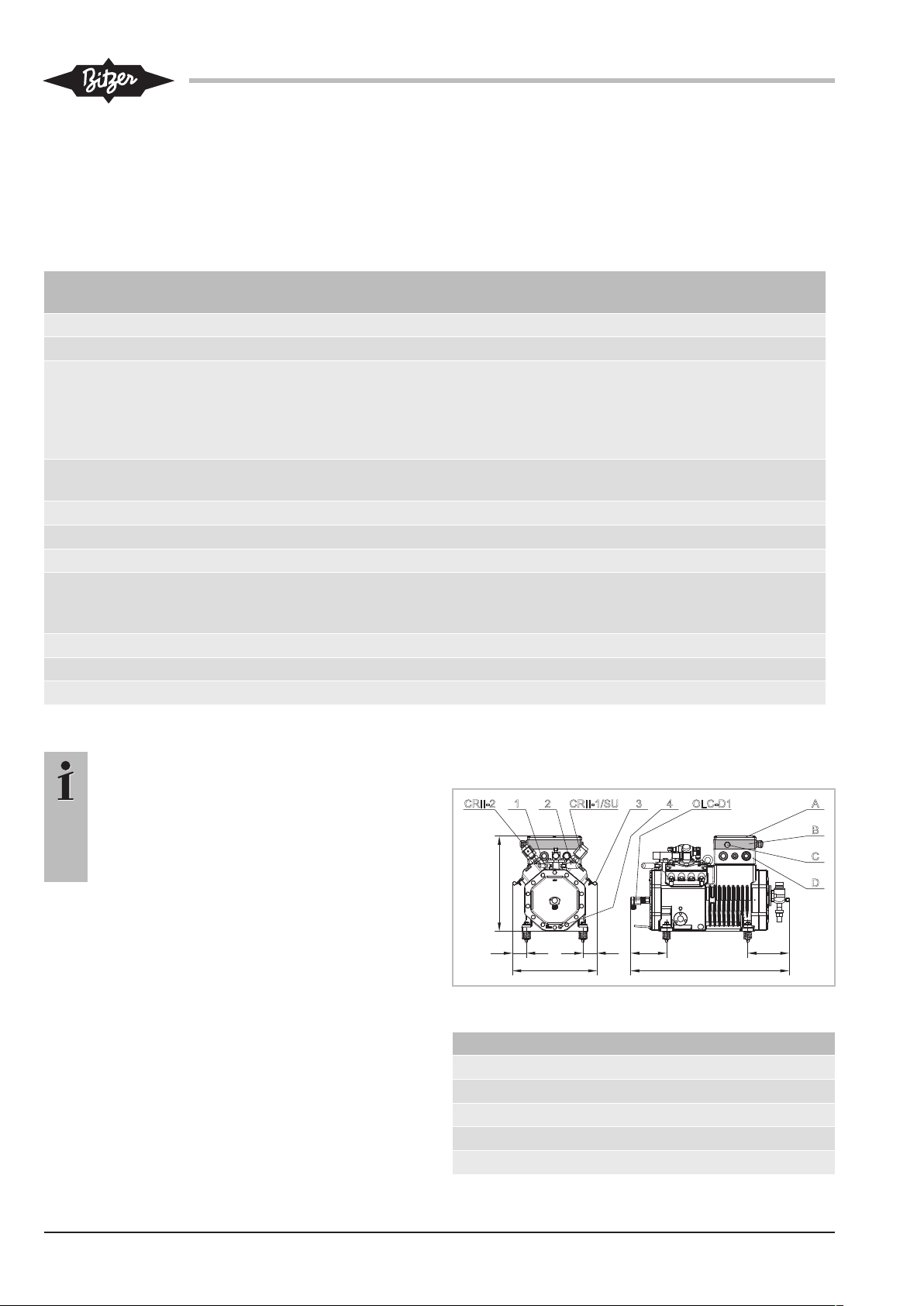
Abb.1: 4VES-6Y .. 4NES-20(Y) mit CM-RC-01
Anschlusspositionen
1 Druckgastemperaturfühler
2 Anschlussposition für Hochdruckschalter
3 Kabelhalter
4 Ölheizung
A Deckel des Anschlusskastens
KT-230-120
Page 21

Anschlusspositionen
B Modulgehäuse (grau)
D LED-Schauglas
D Anschlusskasten
Maßzeichnungen für 4JE-13Y .. 8FE-70(Y) auf Anfrage.
Bei Markteinführung ist an Position 2 ein Hochdruckschalter mit 32bar Abschaltdruck montiert und elektisch am CM-RC-01 angeschlossen. Bei den Verdichtern 4VES-6Y bis 4NES-20(Y) ist es ein Hochdruckwächter bei allen anderen Verdichtern ein Hochdruckbegrenzer.
4 Steuer- und Überwachungsfunktionen
linder-Verdichtern unterhalb 50% und bei 6-ZylinderVerdichtern unterhalb 33%.
Ölheizung
Im Stillstand des Verdichters schaltet das Modul die Ölheizung ein und im Betrieb wieder ab.
Steuerung der Motorschütze beim Verdichteranlauf
Das Verdichtersteuermodul steuert die Ein- und Abschaltzeiten der Motorschütze. Im Auslieferungszustand ist die Zeitrelaissteuerung für den eingebauten
Motor konfiguriert.
Teilwicklungsmotor: Der Kontakt an CN2:2 (K1 Control)
schließt 1s nach dem Freigabesignal. Der Kontakt an
CN2:1 (K2 Control) schließt 0,5s danach. Beide Kontakte bleiben geschlossen, bis der Verdichter abgeschaltet wird.
4.1 Steuerfunktionen
In diesem Kapitel werden alle Steuerfunktionen beschrieben, auch die optionalen.
Leistungsregelung CRII
Das CM-RC-01 passt die Leistung des Verdichters
quasi-stufenlos entsprechend dem Sollwert des übergeordneten Anlagenreglers kontinuierlich an. Dazu
schaltet es die CRII-Magnetventile. 4-Zylinder-Verdichter mit 2 und 6-Zylinder-Verdichter mit 3 installierten
Leistungsreglern werden damit zwischen Volllast und
10% Teillast geregelt, 8-Zylinder-Verdichter zwischen
Volllast und 50%.
Wenn Anlaufentlastung montiert ist, steht eine Zylinderbank weniger für die Leistungsregelung zur Verfügung.
Der Regelbereich für die Leistungsregelung reduziert
sich entsprechend.
Anlaufentlastung SU
Anlaufentlastung kann bei 4- und 6-Zylinder-Verdichtern installiert werden. Das Modul steuert das Magnetventil und sorgt für einen entlasteten Verdichteranlauf.
Verdichterkühlung
Das Verdichtersteuermodul schaltet den Zusatzventilator ab einer Druckgastemperatur von 120°C zu und bei
100°C wieder ab. Erreicht die Druckgastemperatur
135°C wird das CIC zunächst taktend zugeschaltet, ab
140°C im Dauerbetrieb. Solange das CIC aktiv ist, kann
der Verdichter nur im oberen Teillastbereich betrieben
werden. Die Grenze liegt für 4-Zylinder-Verdichter bei
50% und bei 6-Zylinder-Verdichtern bei 66%.
Zur Motorkühlung schaltet das Modul den Zusatzventilator im unteren Teillastbereich bei Bedarf zu, bei 4-Zy-
Stern-Dreieck-Motor: Der Kontakt an Klemme CN2:2
(K1 Control) schließt 1s nach dem Freigabesignal und
öffnet nach weiteren 1,5s. Der Kontakt an Klemme
CN2:1 (K2 Control) schließt 1,5s nach dem Freigabesignal und bleibt geschlossen, bis der Verdichter abgeschaltet wird.
Motor für Direktanlauf: Der Kontakt an Klemme CN2:2
(K1 Control) schließt 1s nach dem Freigabesignal und
öffnet wenn der Verdichter abgeschaltet wird. Der Kontakt an Klemme CN2:1 (K2 Control) ist nicht belegt. Für
Sanftanlauf und Betrieb mit Frequenzumrichter wird
ebenfalls nur ein Motorschütz benötigt.
4.2 Überwachungs- und Schutzfunktionen
Das Verdichtersteuermodul überwacht die Signale
mehrerer Fühler, die an Verdichter oder Saug- und
Druckgasleitung angebracht sein können:
überwachte Funktion Messfühler
Motortemperatur (Stan-
dard)
Druckgastemperatur
(Standard)
Einsatzgrenzen (Opti-
on):
Verflüssigungs- und
Verdampfungstemperatur
Niederdruck (Option) Niederdruckmessumformer
Hochdruck (Option) Hochdruckmessumformer
Motortemperaturfühler
(R1 .. R6)
Druckgastemperaturfühler
(R7)
Nieder- und Hochdruckmessumformer (B7 und B6)
(B7)
(B6)
KT-230-1 21
Page 22
überwachte Funktion Messfühler
Ölversorgung (Stan-
dard)
Ölniveauüberwachung mit
OLC-D1 (F4) bei 4VES-6Y
bis 4NES-20(Y)
Öldifferenzdrucküberwachung mit DP-1 (F4) bei
4JE-13Y bis 8FE-70(Y)
Schalthäufigkeit des
integriert in CM-RC-01
Verdichters (Standard)
Temperatur an beliebi-
optionaler Temperaturfühler
ger Stelle (Option)
Das Verdichtersteuermodul gleicht die gemessenen
Werte mit den programmierten Daten ab. Dabei gibt es
Meldungen über Modbus aus und signalisiert den Betriebszustand durch verschiedenfarbige LEDs, siehe
Kapitel Schutzfunktionen, Seite 28. Bei Betrieb außerhalb der Einsatzgrenzen, Ölmangel oder zu hoher Motortemperatur wird der Verdichter abgeschaltet. Die
Schalthäufigkeit und der Messwert des optionalen
Temperaturfühlers werden überwacht und protokolliert.
5 Elektrischer Anschluss
Das Verdichtersteuermodul im Stillstand des Motors
unter Spannung belassen. Das Modul schaltet die Ölheizung bei Bedarf zu. Dies stellt die Schmierfähigkeit
des Öls auch nach längerem Stillstand sicher.
Modul nur bei geplantem langen Verdichterstillstand
oder für die Wartung spannungsfrei schalten.
5.1 Prinzipschaltbild für Teilwicklungsanlauf
Prinzipschaltbild siehe Abbildung 2, Seite 23. Bei Direktanlauf entfällt Pfad 4: Schütz K2 und Überstromrelais F14 sowie der Kabelanschluss an Klemmleiste
CN2, Klemme 1. Bei Sanftanlauf und Betrieb mit Frequenzumrichter wird ebenfalls nur ein Schütz benötigt.
Bei Betrieb mit Frequenzumrichter beachten: Freigabesignal an das Verdichtersteuermodul erst nach dem Laden des Gleichspannungszwischenkreises beim ersten
Einschalten geben.
5.2 Prinzipschaltbild für Stern-Dreieck-Anlauf
Beim Stern-Dreieck-Anlauf werden die Motorschütze
nicht entsprechend der Beschriftung der Klemmen am
CM-RC-01 angeschlossen, siehe Abbildung 3, Seite
24.
5.3 Legende zu den Prinzipschaltbildern
Abk. Bauteil
B1 Befehl für Verdichteranlauf (Freigabesignal
vom Anlagenregler)
B6 Hochdruckmessumformer
B7 Niederdruckmessumformer
F1 Hauptsicherung
F2 Verdichtersicherung
F3 Steuersicherung
F4 Ölüberwachung: 4VES-6Y .. 4NES-20(Y):
OLC-D1 / 4JE-13Y .. 8FE-80(Y): DP-1
F5 Hochdruckschalter
F13 Überstromrelais "Motor" (1. Teilwicklung und
Y/Δ)
F14 Überstromrelais "Motor" (2. Teilwicklung)
F17 Steuertransformatorsicherung
H3 Leuchte "Sammelstörung"
K1 Schütz "1. Teilwicklung" (PW) oder Haupt-
schütz (Y/Δ)
K2 Schütz "2. Teilwicklung" (PW) oder Dreieck-
schütz (Y/Δ)
K3 Sternschütz (Y/Δ)
M1 Verdichter
M2 Zusatzventilator
Q1 Hauptschalter
R1..6 PTC-Fühler in Motorwicklung
R7 Druckgastemperaturfühler
R8 Ölheizung
R11 Optionaler Temperaturfühler (nicht im Liefer-
umfang enthalten)
S1 Steuerschalter (ein/aus)
S2 Entriegelung des CM-RC-01
T1 Steuertransformator (Beispiel für 230V)
Y1 Magnetventil "Anlaufentlastung SU"
Y3-1 Magnetventil "1. Leistungsregler CRII"
Y3-2 Magnetventil "2. Leistungsregler CRII"
Y3-3 Magnetventil "3. Leistungsregler CRII" (nur
bei BE6-Verdichtern)
Y5 CIC-Einspritzventil
Tab.2: Bauteile der Prinzipschaltbilder
KT-230-122
Page 23
1 2 3 4
CN1
L N
CN2
K2control
Supply
Supply
K1control
RelayC
RelayNC
CN3
HPS
HPS
CN4
Heater
Heater
CN5
Add. fan
Add. fan
CN6
CR-1
CR-1
CR-2
CR-2
CR-3
CR-3
Injection
Injection
5 6 7 8
CN7
1 2 3 4 1 2
CN9
CN10
1 2 3 4 5 6
CN12
1 2 3 4
CN11
1 2
CN13
1 2 3 4
CN14
24VSup
GND
Signal
GND
PTC
PTC
Signal
GND
Signal
GND
5VSup
Signal
GND
5VSup
Signal
GND
Input
GND
Data+
Data–
Sup In
GND
24VSup
GND
Signal
GND
21 3 4 1 2 1 N 1 N 1 N 3 N 5 N 7 N
CM-RC-01
4321 876
5
13
1211
109
14
15
16
17
18 19 20
21 22
S2
F2
L1L2L3
PE
F1
Q1
1
0
K1
11
K2
10
M 3~
F13
8
F17
230V
T1
F3 4A T
PE
S1
01
F13
2
B1
H3
W1
V1
U1
V2
U2
W2
M1
K2
Y3-2
Y5
4/4/4
grau/grey
braun/brown
orangerosa
pink
blau/blue
B6
B7
Modbus
RS485
PE
0 .. 10V
R7
PE
F5
P>
R8
M2
Y3-1
1 2
CT
CT
CN8
R11
132
1
3
2
R1..6
F14
4
F14
8
2/2/2
K1
(2CP5-71-49)
(2CP5-71-47)
F4
F4
OLC-D1
DP-1
CN9:3
CN9:4
Y3-3
M
1~
Abb.2: Prinzipschaltbild für Teilwicklungsanlauf
KT-230-1 23
Page 24
1 2 3 4
CN1
L N
CN2
K2control
Supply
Supply
K1control
RelayC
RelayNC
CN3
HPS
HPS
CN4
Heater
Heater
CN5
Add. fan
Add. fan
CN6
CR-1
CR-1
CR-2
CR-2
CR-3
CR-3
Injection
Injection
5 6 7 8
CN7
1 2 3 4 1 2
CN9
CN10
1 2 3 4 5 6
CN12
1 2 3 4
CN11
1 2
CN13
1 2 3 4
CN14
24VSup
GND
Signal
GND
PTC
PTC
Signal
GND
Signal
GND
5VSup
Signal
GND
5VSup
Signal
GND
Input
GND
Data+
Data–
Sup In
GND
24VSup
GND
Signal
GND
21 3 4 1 2 1 N 1 N 1 N 3 N 5 N 7 N
CM-RC-01
4321 876
5
13
1211
109
14
15
16
17
18 19 20
21 22
S2
F2
L1L2L3
PE
F1
Q1
1
0
K1
10
K2
11
M 3~
F13
8
K3
12
F17
F3 4A T
PE
S1
01
F13
2
B1
H3
W1
V1
U1
V2
U2
W2
M1
2/2/2
K1
K2
K3
12
Y3-2
Y5
4/4/4
grau/grey
braun/brown
orangerosa
pink
blau/blue
F4
B6
B7
Modbus
RS485
PE
0 .. 10V
5/5/5K311
R7
PE
R8
M2
Y3-1
1 2
CT
CT
CN8
R11
132
1
3
2
R1..6
F5
P>
F4
Y3-3
(2CP5-71-49)
(2CP5-71-47)
OLC-D1
DP-1
CN9:3
CN9:4
230V
T1
M
1~
Abb.3: Prinzipschaltbild für Stern-Dreieck-Anlauf
5.4 Motoranlauffunktion
KT-230-124
Page 25
Das Verdichtersteuermodul steuert die Ein- und Abschaltzeiten der Motorschütze. Im Auslieferungszustand ist die Zeitrelaissteuerung für den eingebauten
Motor konfiguriert.
5.5 Verkabelung im Auslieferungszustand
Folgende Bauteile sind im Auslieferungszustand vorinstalliert und verkabelt:
• Ölheizung (Standard, R8)
• Ölüberwachung (Standard, F4)
• Druckgastemperaturfühler (Standard, R7)
• bei Ausstattungsvariante A zusätzlich: 2 Magnetventile für Leistungsregelung (Y3-1 und Y3-2)
• bei Ausstattungsvariante B zusätzlich: 1 Magnetventil für Anlaufentlastung (Y1) und 1 Magnetventil für
Leistungsregelung (Y3-2)
• und in der Markteinführungsphase zusätzlich: Hochdruckschalter (Standard, F5)
Diese Bauteile sind im Prinzipschaltbild etwas dunkler
grau dargestellt. Eingriffe an diesen Bauteilen und ihrer
Verkabelung sind nicht notwendig und sollten keinesfalls ohne Rücksprache mit BITZER ausgeführt werden.
Alle weiteren optionalen Bauteile sind hellgrau dargestellt. Sie werden als Beipack geliefert und müssen
montiert und verkabelt werden.
6 Kabel anschließen
Verdichtersteuermodul gemäß Prinzipschaltbildern
elektrisch anschließen. Sicherheitsnormen EN 60204,
IEC 60364 und nationale Schutzbestimmungen berücksichtigen.
WARNUNG
Gefahr von elektrischem Schlag!
Vor Arbeiten im Anschlusskasten, im Modulgehäuse und an elektrischen Leitungen: Hauptschalter ausschalten und gegen Wiedereinschalten sichern!
Vor Wiedereinschalten Anschlusskasten und
Modulgehäuse schließen!
HINWEIS
Beschädigung oder Ausfall des Verdichtersteuermoduls möglich!
An die Klemmen von CN7 bis CN12 keine
Spannung anlegen – auch nicht zum Prüfen!
An die Klemmen von CN13 maximal 10V anlegen!
An die Klemme 3 von CN14 maximal 24V, an
die anderen Klemmen keine Spannung anlegen!
Das CM-RC-01 ist direkt oberhalb des Anschlusskastens für den Leistungsanschluss des Verdichters eingebaut. Bei den 8-Zylinder-Verdichtern befindest es sich
im Anschlusskasten.
Verdichterleistungsanschluss
5.6 Hochdruckschalter
Für jeden Verdichter muss nach EN 378 ein Hochdruckschalter (F5) zur Sicherheitsabschaltung in der Sicherheitskette vorgesehen werden. Dieser Schalter
kann direkt am Verdichter montiert und über das CMRC-01 in die elektrische Sicherheitskette eingebunden
werden. Montageposition siehe Kapitel Maßzeichnungen, Seite 20, Kabel entsprechend Prinzipschaltbildern
an Klemmleiste CN3 anschliessen.
Der Einbau eines Niederdruckschalters ist nicht notwendig, wenn die optionale Einsatzgrenzüberwachung
installiert ist. Dann ist die automatische Niederdruckabschaltfunktion des Verdichtersteuermoduls aktiv.
• Deckel des Modulgehäuses entfernen.
• Bei 4- und 6-Zylinder-Verdichtern ist das Modulgehäuse mit dem Anschlusskasten für den Leistungsanschluss des Verdichters verschraubt. Modulgehäuse abnehmen. Darauf achten, dass die beiden
orangenen Kabel und der Schutzleiter nicht beschädigt werden und dass sich die Anschlüsse nicht lösen. Die orangenen Kabel sind die Motortemperaturfühlerkabel.
• Leistungskabel für den Verdichtermotor entsprechend Aufkleber unten am Modulgehäuse und Betriebsanleitung KB-104 anschließen. Bei 8-ZylinderVerdichtern befindet sich der Aufkleber an der Innenseite des Anschlusskastendeckels.
• Beide orangene Kabel und Schutzleiter: Kabel prüfen. Kabelanschlüsse an der Stromdurchführungsplatte auf festen Sitz prüfen.
• Bei 4- und 6-Zylinder-Verdichtern das Modulgehäuse
wieder aufsetzen.
KT-230-1 25
Page 26
6.1 Erforderliche elektrische Anschlüsse am CMRC-01
• Modulleistungsanschluss an Klemmleiste CN1
(115 .. 230V +10%/-15%, 50/60Hz)
– Klemme 1: L
– Klemme 2: N
• Befehl für Verdichteranlauf (Freigabesignal vom An-
lagenregler, B1)
Das Freigabesignal vom Anlagenregler ist in Pfad 8
als erstes Glied der Sicherheitskette vorgesehen.
Diese Freigabeinformation muss an das Verdichtersteuermodul weitergegeben werden, es aktiviert die
Zeitrelaissteuerung für die Motorschütze K1, K2 und
K3.
Montageposition: An Druckgas- bzw. Sauggasleitung,
möglichst dicht an den Ventilen mit je einem Kältemittelschlauch anschließen. Länge des Kältemittelschlauchs: mindestens 200mm, um eine Betauung des
Messumformers zu vermeiden.
Elektrischer Anschluss: Kabel am CM-RC-01 entsprechend Prinzipschaltbildern an Klemmleiste CN12 anschließen.
Zusatzventilator
Ventilatorfüße an den Zylinderköpfen montieren. Siehe
beiliegende Technische Information KT-140.
Das Kabel des Zusatzventilators am CM-RC-01 entsprechend Prinzipschaltbildern an Klemmleiste CN5
anschließen.
– Sicherheitskette (Freigabesignal) an Klemmleiste
CN2, Klemme 3 anschließen.
– Verdichtersteuermodul als letztes Glied in die Si-
cherheitskette einbinden.
– Alle Motorschütze entsprechend Prinzipschaltbil-
dern an Klemmleiste CN2 anschließen.
• Regelsignal vom Anlagenregler (Sollwert für die
Leistungsregelung, CRII)
Dieser Anschluss ist nur erforderlich, wenn der Verdichter mit Leistungsreglern ausgestattet ist.
– Modbuskabel an Klemmleiste CN14 anschließen.
– Oder Analogsignal an Klemmleiste CN13 an-
schließen.
• Modulgehäuse schließen:
– Kabelanschlüsse der Schutzleiter auf festen Sitz
prüfen.
– Deckel des Modulgehäuses aufsetzen und ver-
schrauben.
6.2 Optionale elektrische Anschlüsse
CIC-System
WARNUNG
Verdichter steht unter Druck!
Schwere Verletzungen möglich.
Verdichter auf drucklosen Zustand bringen!
Schutzbrille tragen!
Montage: Einspritzdüse am CIC-Anschluss anschließen. Diese Position ist in der Verdichterbetriebsanleitung KB-104 beschrieben (Maßzeichnungen: Anschlussposition 4). Bei 6-Zylinder-Verdichtern werden 2
Düsen montiert.
• Stopfen am Verdichter entfernen.
• Gewindebohrung reinigen und prüfen.
• Dichtung und Einspritzdüse montieren, entsprechend KT-130, Kapitel 5.4 "Einspritzdüse und Einspritzventil".
• Magnetspule auf den Anker aufdrücken. Sie rastet
ein.
• Gerätesteckdose aufstecken und verschrauben
(5Nm).
Einsatzgrenzüberwachung
Hoch- und Niederdruckmessumformer B6 und B7 werden als Beipack geliefert, wenn die Option "Einsatzgrenzüberwachung" bestellt wurde. Sie müssen in der
Anlage montiert, mit dem CM-RC-01 verkabelt und mit
der BEST Software aktiviert werden. Die beiden Messumformer dürfen nicht vertauscht werden. Sie unterscheiden sich durch die eingestanzte Bauteilnummer:
• Hochdruckmessumformer B6: 2CP5-71-47
• Niederdruckmessumformer B7: 2CP5-71-49
• Kabel am CM-RC-01 entsprechend Prinzipschaltbildern an Klemmleiste CN6, Klemmen 7 und 8 anschließen.
Dritter Leistungsregler Y3-3
Bei 6-Zylinder-Verdichtern kann ein dritter Leistungsregler aktiviert werden. Der dafür notwendige CRII-Zylinderkopf ist im Auslieferungszustand montiert, wenn
der Verdichter so bestellt wurde. Er kann auch nachgerüstet werden. Montage des Magnetventils und Montage des CRII-Zylinderkopfs siehe Technische Information KT-101.
KT-230-126
Page 27
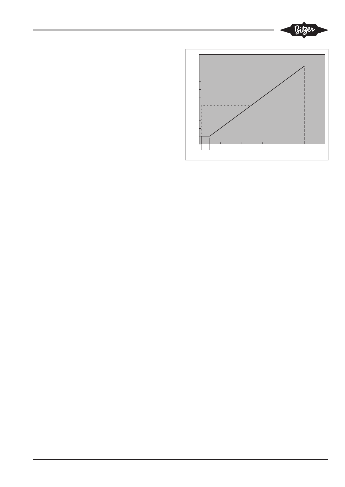
Elektrischer Anschluss: Kabel am CM-RC-01 entspre-
CRII
0 2 4 6 8 10 12
U [V]
0 .. 10 V
min
min
1
80%
60%
40%
20%
0%
0,2
*
chend Prinzipschaltbildern an Klemmleiste CN6, Klemmen 5 und 6 anschließen.
Optionaler Temperaturfühler R11
Ein optionaler PT1000-Temperaturfühler kann an der
Steuerung angeschlossen werden. Die Daten dieses
Temperaturfühlers werden protokolliert, haben auf
Steuerung und Überwachung jedoch keinen Einfluss.
Elektrischer Anschluss: Kabel am CM-RC-01 entsprechend Prinzipschaltbildern an Klemmleiste CN11,
Klemmen 1 und 2 anschließen.
Die BEST Software erkennt diesen Fühler automatisch.
6.3 CRII mit Anlagenregler steuern
CRII kann über Modbus oder über ein Analogsignal gesteuert werden. Betrieb des Verdichters bei reduzierter
Leistung ist nur innerhalb der Teillasteinsatzgrenzen für
das jeweilige Kältemittel zulässig. Minimale Restleistung: 10%. Anlagenregler entsprechend programmieren. Einsatzgrenzen siehe BITZER Software und Technische Information KT-101.
6.3.1 Steuerung über Analogsignal
Die Verdichterleistung wird über ein Gleichspannungssignal gesteuert. Diese Art der Steuerung eignet sich
vor allem für Anlagen mit einfachen Reglern, die mit einem Ausgang für 0 bis 10V und einem Relais ausgestattet sind und wenn die BEST Software am ModbusAnschluss benutzt werden soll.
• Anschluss auf Klemmleiste CN13, Klemmen 1 und 2.
• Regelsignal: 0 bis 10V Gleichspannung eines Analogausgangs des Anlagenreglers
• Regelgüte: ±0,5% bei 100%
• lineare Regelcharakteristik, siehe Abbildung.
Abb.4: Regelcharakteristik
• CR
: Ausgehend von 100% kann die Verdichterleis-
min
tung auf 10% reduziert werden, wenn jeder Zylinderkopf mit CRII-Leistungsreglern ausgestattet ist.
• CR
* und gestrichelte Linie: Der Regelbereich ver-
min
ringert sich, wenn der nicht jede Zylinderbank mit
Leistungsreglern ausgestattet ist. Die minimale Leistungsstufe von 50% ist die untere Regelgrenze bei
8-Zylinder-Verdichtern und bei 4-Zylinder-Verdichtern mit einem Leistungsregler. In diesem Fall regelt
das CM-RC-01 bei einem Steuersignal unter 5V auf
50% Restleistung.
6.3.2 Steuerung über Modbus-Schnittstelle
Kabel an Klemmleiste CN14 einstecken oder anschließen. Siehe Prinzipschaltbilder.
In diesem Fall können die Betriebsparameter über
Bluetooth mit der BEST Software überwacht werden.
6.4 Betriebsüberwachung mit der BEST Software anschließen
KT-230-1 27
• BEST Schnittstellenkonverter an Klemmleiste CN14
anschließen (Modbus).
Die Leistungsregelung muss in diesem Fall über das
Analogsignal an Klemmleiste CN13 vorgegeben werden.
Die Best Software kann auch über eine BluetoothSchnittstelle auf das Verdichtersteuermodul zugreifen,
siehe Kapitel Kommunikation über die BEST Software,
Seite 30. Diese Schnittstelle ist bei Markteinführung
noch nicht verfügbar.
Page 28

7 Schutzfunktionen
Bei normalem Betrieb leuchtet die grüne LED. Die
LEDs sind über ein Schauglas im Modulgehäuse zu sehen, siehe Kapitel Maßzeichnungen, Seite 20.
Bevor der Messwert eines Sensors eine kritische Grenze erreicht, gibt das Verdichtersteuermodul über die
Modbus-RS485-Schnittstelle (CN14) eine Warnmeldung aus. In diesem Fall leuchtet die gelbe LED. Wenn
ein Wert deutlich außerhalb des zulässigen Bereichs
gemessen wird, schaltet das Verdichtersteuermodul
den Motor sofort ab. Die rote LED leuchtet.
Die blaue LED leuchtet, wenn Daten über die ModbusSchnittstelle übertragen werden.
Je nach Messwert sind bis zu 3 Alarmstufen definiert.
Diese Alarme werden aufgezeichnet und mit der BEST
Software angezeigt. Die Alarmstufen ermöglichen es,
einen Anlagenregler so zu programmieren, dass der
Verdichter innerhalb der Einsatzgrenzen ausgeregelt
werden kann.
Warnung (Warning)
Die Warnschwelle ist überschritten, wenn die Einsatzgrenze fast erreicht ist. Die gelbe LED leuchtet. Diese
ist eine Software-Meldung und kein Sicherheitshinweis.
Die Warnung bezieht sich ausschließlich auf den kritischen Betriebszustand des Verdichters.
Kritischer Alarm (Critical)
Der Abschaltwert ist überschritten. Die gelbe LED
leuchtet. Wenn der betreffende Messwert innerhalb 30
s nicht wieder unterschritten ist, wird der Verdichter abgeschaltet. Diese Abschaltung wird in der Alarmliste als
Störung (Fault) eingestuft.
Störung (Fault)
Abschaltwert zu weit oder zu lange überschritten. Der
Verdichter wird abgeschaltet. Die rote LED leuchtet.
überwachte Funktion Verzögerungszeit
Warnung kritischer Alarm Störung
nach Verdichteranlauf
Druckgastemperatur --- >135°C --- >150°C
verriegelt nach
20s
Ölversorgung 90 s 5s --- verriegelt nach
90s
Schalthäufigkeit des Verdichters
--- > 8 Verdichterab-
schaltungen inner-
--- ---
halb einer Stunde
KT-230-128
Page 29

überwachte Funktion Verzögerungszeit
Warnung kritischer Alarm Störung
nach Verdichteranlauf
Einsatzgrenzen, Option
(Verflüssigungstemperatur,
Verdampfungstemperatur)
120 s <2K innerhalb
der Einsatzgrenze
>2K außerhalb
der Einsatzgrenze
verriegelt nach
>4K außerhalb
der Einsatzgrenze
verriegelt sofort
30s
Niederdruck, Option --- --- --- < 0,2 bar / < in
BEST Software
eingegebener relativer Druck: verriegelt sofort
Hochdruck, Option --- --- --- > 32bar / > in
BEST Software
eingegebener relativer Druck:
verriegelt sofort
Entriegeln
Spannungsversorgung (L/N) mindestens 5 s lang unterbrechen, über Modbus-Befehl oder mit der BEST Software zurücksetzen im Menü ALARME, Schaltfläche ZU-
RÜCKSETZEN.
KT-230-1 29
Page 30

8 Betriebsparameter mit der BEST Software
überwachen
Die BEST Software zeigt alle aktiven Alarme und folgende Betriebsparameter an:
• Leistungsregelstufe
• Verflüssigungstemperatur
• Verdampfungstemperatur
• Niederdruck
• Hochdruck
• Druckgastemperatur
Das Menü KONFIGURATION mit Fenster HAUPTEINSTELLUN-
GEN erscheint. Das Verdichtersteuermodul ist jetzt mit
dem mobilen Endgerät verbunden.
8.2 CM-RC-01 mit der BEST Software konfigurieren
Das Verdichtersteuermodul CM-RC-01 ist im Auslieferungszustand für den Verdichter, in den es eingebaut
ist, und für dessen Motor konfiguriert. Datum und Uhrzeit sollten geprüft und ggf. angepasst werden. Installierte Optionen müssen anschließend ebenfalls konfiguriert werden. Je nach Anlagenauslegung kann es sinnvoll sein einige weitere Parameter anzupassen.
8.1 Kommunikation über die BEST Software
Notwendige Voraussetzungen
• Mobiles Endgerät
– mit dem Betriebssystem Windows XP oder neuer
– mit USB-Anschluss oder mit Bluetooth
– mit installierter BEST Software
Die BEST Software kann kostenlos von der
BITZER Internetseite www.bitzer.de heruntergeladen werden.
• Datenverbindung
– über BEST Schnittstellenkonverter
– oder über Bluetooth 4.0. Reichweite etwa 3m.
• Wenn der BEST Schnittstellenkonverter verwendet
wird, muss der Verdichter über den Analoganschluss
(CN13) geregelt werden. Über den Modbus-Anschluss ist nicht gleichzeitig Leistungsregelung und
eine BEST Datenverbindung möglich. Bluetooth ist
bei Markteinführung noch nicht vorhanden.
Kommunikation einrichten
8.2.1 Aktuelle Uhrzeit einstellen
Mit der BEST Software das programmierte Datum und
die Uhrzeit prüfen:
• Menü KONFIGURATION Fenster HAUPTEINSTELLUNGEN Zeilen DATUM und UHRZEIT prüfen.
• Daten ggf. korrigieren.
8.2.2 Motoranlauffunktion prüfen
Das Verdichtersteuermodul steuert die Ein- und Abschaltzeiten der Motorschütze. Im Auslieferungszustand ist die Zeitrelaissteuerung für den eingebauten
Motor konfiguriert. Mit der BEST Software kann die
konfigurierte Motoranlaufmethode (Teilwicklung, SternDreieck oder Direktanlauf) geprüft und geändert werden.
In der BEST Software prüfen und bei Bedarf anpassen:
• Menü KONFIGURATION, Fenster MOTORANLAUF-FUNKTION.
Bei Betrieb mit Frequenzumrichter oder Softstarter
muss Direktanlauf eingestellt sein. Bei Bedarf passende Motoranlauffunktion einstellen.
In jedem Fall läuft der Verdichtermotor 1s nach dem
Freigabesignal des übergeordneten Anlagenreglers an.
• Nur bei Kommunikation über den BEST Schnittstellenkonverter: Kabel an Verdichtersteuermodul
(CN14) und mobilem Endgerät einstecken.
• Mobiles Endgerät einschalten und BEST Software
starten.
Ein Anzeigefenster der verfügbaren Geräte öffnet
sich.
• CM-RC-01 auswählen.
• Schaltfläche VERBINDEN anklicken.
• Nur bei Kommunikation über Bluetooth: Berechtigungscode eingeben.
8.2.3 Einsatzgrenzüberwachung aktivieren
◦ Voraussetzung: Hoch- und Niederdruckmessumfor-
mer sind installiert.
• Das Kältemittel in der BEST Software einstellen: im
Menü HAUPTEINSTELLUNGEN, Fenster KÄLTEMITTEL das
verwendete Kältemittel auswählen.
• In Menü KONFIGURATION Fenster SCHUTZFUNKTIONEN in
den Zeilen HOCHDRUCKSCHALTER: ABSCHALTWERT und
NIEDERDRUCKSCHALTER: ABSCHALTWERT zur Anlage passende Grenzwerte in relativen Drücken eingeben.
Grundeinstellung: 32bar / 0,2bar, jeweils relative
Drücke. Der Hochdruck kann nicht weiter erhöht
werden.
KT-230-130
Page 31

8.3 Datenaufzeichnung
Alle überwachten Betriebsparameter sowie alle Alarmmeldungen werden intern gespeichert:
• alle Betriebsparameter in 10-Sekunden-Intervallen
mindestens der letzten 14Tage
• detailliert die letzten 10 Störungen
• Statistiken für die letzten 365 Tage
Diese Daten können mit der BEST Software als Datei
ausgegeben werden. Sie erlauben eine Analyse des
Anlagenbetriebs und ggf. eine detaillierte Fehlerdiagnose.
KT-230-1 31
Page 32

80306301 // 05.2016
Subject to change
Änderungen vorbehalten
BITZER Kühlmaschinenbau GmbH
Eschenbrünnlestraße 15 // 71065 Sindelfingen // Germany
Tel +49 (0)70 31 932-0 // Fax +49 (0)70 31 932-147
[email protected] // www.bitzer.de
Subject to change // Änderungen vorbehalten // Toutes modifications réservées // 80306301 // 05.2016
 Loading...