

Page 1

INSTRUCTION BOOK
TERMALINE® LOAD RESISTOR
SERIES 8755/8756
Bird® Electronic Corporation
30303 Aurora Road
Cleveland (Solon), Ohio 44139
Sales & Technical Support: 440-248-1200
Sales email: sales@bird-technologies.com
Technical Support email: atechapp@bird-technologies.com
866-695-4569 toll free
©Copyright 2010 by Bird Electronic Corporation
Instruction Book Part Number 920-8755/56 Rev. C
Termaline
of Bird Electronic Corporation
®
is a Registered Trademark
Page 2

I am not blank
Page 3
Safety Precautions
The following are general safety precautions that are not necessarily related to any
specific part or procedure, and do not necessarily appear elsewhere in this publica
tion. These precautions must be thoroughly understood and apply to all phases of
operation and maintenance.
WARNING
Keep Away From Live Circuits
Operating Personnel must at all times observe general safety precautions. Do not
replace components or make adjustments to the inside of the test equipment with
the high voltage supply turned on. To avoid casualties, always remove power.
WARNING
Shock Hazard
Do not attempt to remove the RF transmission line while RF power is present.
WARNING
Do Not Service Or Adjust Alone
Under no circumstances should any person reach into an enclosure for the
purpose of service or adjustment of equipment except in the presence of
someone who is capable of rendering aid.
WARNING
Safety Earth Ground
An uniterruptible earth safety ground must be supplied from the main power
source to test instruments. Grounding one conductor of a two conductor power
cable is not sufficient protection. Serious injury or death can occur if this
grounding is not properly supplied.
-
WARNING
Resuscitation
Personnel working with or near high voltages should be familiar with modern
methods of resuscitation.
WARNING
Remove Power
Observe general safety precautions. Do not open the instrument with the power on.
Safety Symbols
WARNING
Warning notes call attention to a procedure, which if not correctly performed,
could result in personal injury.
CAUTION
Caution notes call attention to a procedure, which if not correctly performed,
could result in damage to the instrument.
Note: Calls attention to supplemental information.
i
Page 4
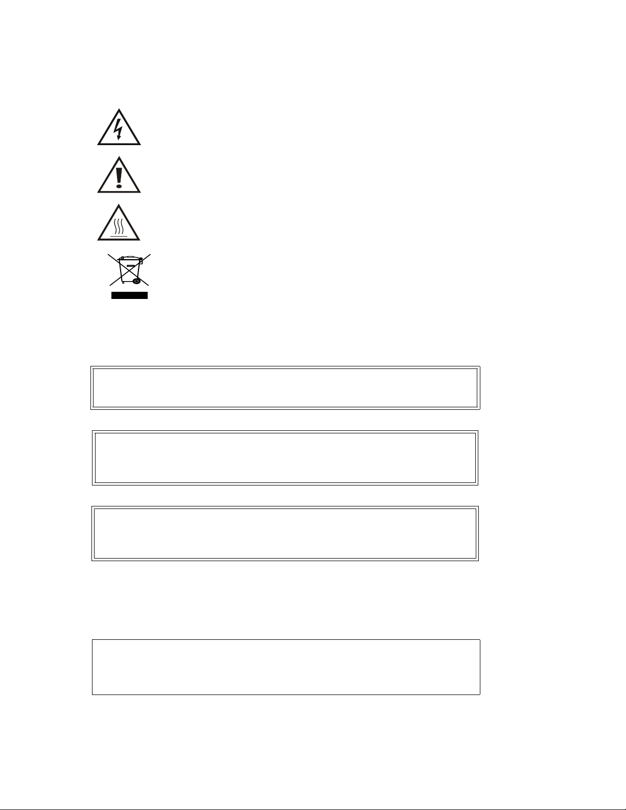
This symbol indicates that a shock hazard exists if the precautions in the instruction manual are not followed.
The caution symbol appears on the equipment indicating there
is important information in the instruction manual regarding
that particular area.
This symbol indicates that the unit radiates heat and should not
be touched while hot.
This symbol appears on the equipment and indicates the
requirement for separate collection of discarded electrical and
electronic equipment in accordance with the European Union
Directive 2002/96/EC.
Warning Statements
The following safety warnings appear in the text where there is danger to operating and maintenance personnel, and are repeated here for emphasis.
WARNING
Never attempt to disconnect the equipment from the transmission line while RF
power is being applied. Leaking RF energy is a potential health hazard.
On page 7 and 9.
WARNING
Never attempt to connect or disconnect RF equipment from the transmission
line while RF power is being applied. Leaking RF energy is a potential health
hazard.
On page 10.
WARNING
The resistor used in this load consists of a resistive film on a special substrate.
If the substrate is broken, there will probably be sharp pieces or splinters
inside the load housing. Caution should be exercised to avoid possible injury.
On page 14.
Caution Statements
The following equipment cautions appear in the text and are repeated here for
emphasis.
CAUTION
DO NOT disconnect the water flow switch leads from the control assembly. Any
operation of the load without a properly functioning cooling system will cause
almost immediate destruction of the resistor element.
On page 7.
ii
Page 5

Safety Statements
USAGE
ANY USE OF THIS INSTRUMENT IN A MANNER NOT SPECIFIED BY THE
MANUFACTURER MAY IMPAIR THE INSTRUMENT’S SAFETY
PROTECTION.
USO
EL USO DE ESTE INSTRUMENTO DE MANERA NO ESPECIFICADA POR EL
FABRICANTE, PUEDE ANULAR LA PROTECCIÓN DE SEGURIDAD DEL
INSTRUMENTO.
BENUTZUNG
WIRD DAS GERÄT AUF ANDERE WEISE VERWENDET ALS VOM
HERSTELLER BESCHRIEBEN, KANN DIE GERÄTESICHERHEIT
BEEINTRÄCHTIGT WERDEN.
UTILISATION
TOUTE UTILISATION DE CET INSTRUMENT QUI N’EST PAS
EXPLICITEMENT PRÉVUE PAR LE FABRICANT PEUT ENDOMMAGER LE
DISPOSITIF DE PROTECTION DE L’INSTRUMENT.
IMPIEGO
QUALORA QUESTO STRUMENTO VENISSE UTILIZZATO IN MODO
DIVERSO DA COME SPECIFICATO DAL PRODUTTORE LA PROZIONE DI
SICUREZZA POTREBBE VENIRNE COMPROMESSA.
iii
Page 6

SERVICE
SERVICING INSTRUCTIONS ARE FOR USE BY SERVICE - TRAINED
PERSONNEL ONLY. TO AVOID DANGEROUS ELECTRIC SHOCK, DO NOT
PERFORM ANY SERVICING UNLESS QUALIFIED TO DO SO.
SERVICIO
LAS INSTRUCCIONES DE SERVICIO SON PARA USO EXCLUSIVO DEL
PERSONAL DE SERVICIO CAPACITADO. PARA EVITAR EL PELIGRO DE
DESCARGAS ELÉCTRICAS, NO REALICE NINGÚN SERVICIO A MENOS
QUE ESTÉ CAPACITADO PARA HACERIO.
WARTUNG
ANWEISUNGEN FÜR DIE WARTUNG DES GERÄTES GELTEN NUR FÜR
GESCHULTES FACHPERSONAL.
ZUR VERMEIDUNG GEFÄHRLICHE, ELEKTRISCHE SCHOCKS, SIND
WARTUNGSARBEITEN AUSSCHLIEßLICH VON QUALIFIZIERTEM
SERVICEPERSONAL DURCHZUFÜHREN.
ENTRENTIEN
L’EMPLOI DES INSTRUCTIONS D’ENTRETIEN DOIT ÊTRE RÉSERVÉ AU
PERSONNEL FORMÉ AUX OPÉRATIONS D’ENTRETIEN. POUR PRÉVENIR
UN CHOC ÉLECTRIQUE DANGEREUX, NE PAS EFFECTUER D’ENTRETIEN
SI L’ON N’A PAS ÉTÉ QUALIFIÉ POUR CE FAIRE.
ASSISTENZA TECNICA
LE ISTRUZIONI RELATIVE ALL’ASSISTENZA SONO PREVISTE
ESCLUSIVAMENTE PER IL PERSONALE OPPORTUNAMENTE
ADDESTRATO. PER EVITARE PERICOLOSE SCOSSE ELETTRICHE NON
EFFETTUARRE ALCUNA RIPARAZIONE A MENO CHE QUALIFICATI A
FARLA.
iv
Page 7

CONNECT INTERLOCK TO TRANSMITTER BEFORE OPERATING.
BRANCHER LE VERROUILLAGE À L'ÉMETTEUR AVANT EMPLOI.
CONECTE EL INTERBLOQUEO AL TRANSMISOR ANTES DE LA OPERACION.
VOR INBETRIEBNAHME VERRIEGELUNG AM SENDER ANSCHLIESSEN.
PRIMA DI METTERE IN FUNZIONE L'APPARECCHIO, COLLEGARE IL
DISPOSITIVO DI BLOCCO AL TRASMETTITORE.
v
Page 8

About This Manual
This manual covers the operating and maintenance instructions for the following
models
8755 8756
Changes to this Manual
We have made every effort to ensure this manual is accurate. If you discover any
errors, or if you have suggestions for improving this manual, please send your
comments to our Solon, Ohio factory. This manual may be periodically updated.
When inquiring about updates to this manual refer to the part number and revi
sion on the title page.
Literature Contents
Introduction — Describes the features of the load resistor, lists equipment sup-
plied and optional equipment, and provides power-up instructions.
Theory of Operation — Describes how the load resistor works.
Installation — Describes the power supply and load connection instructions.
Operating Instructions — Describes the base level operation instructions.
Maintenance — Lists routine maintenance tasks as well as troubleshooting for
common problems. Specifications and parts information are also included.
-
vi
Page 9

Table of Contents
Safety Precautions. . . . . . . . . . . . . . . . . . . . . . . . . . . . . . . . . . . . . . . . . . . . . . . . i
Safety Symbols . . . . . . . . . . . . . . . . . . . . . . . . . . . . . . . . . . . . . . . . . . . . . . . . . . . i
Warning Statements . . . . . . . . . . . . . . . . . . . . . . . . . . . . . . . . . . . . . . . . . . . . . . ii
Caution Statements . . . . . . . . . . . . . . . . . . . . . . . . . . . . . . . . . . . . . . . . . . . . . . . ii
Safety Statements . . . . . . . . . . . . . . . . . . . . . . . . . . . . . . . . . . . . . . . . . . . . . . . iii
About This Manual . . . . . . . . . . . . . . . . . . . . . . . . . . . . . . . . . . . . . . . . . . . . . . vi
Changes to this Manual . . . . . . . . . . . . . . . . . . . . . . . . . . . . . . . . . . . . . . . . . . . vi
Literature Contents . . . . . . . . . . . . . . . . . . . . . . . . . . . . . . . . . . . . . . . . . . . . . . vi
Chapter 1 Introduction. . . . . . . . . . . . . . . . . . . . . . . . . . . . . . . . . . . . . . . . . . . . 1
Purpose and Function . . . . . . . . . . . . . . . . . . . . . . . . . . . . . . . . . . . . . . . . . . . . . 1
Optional Equipment . . . . . . . . . . . . . . . . . . . . . . . . . . . . . . . . . . . . . . . . . . . . . . 1
Direct Power Measurement . . . . . . . . . . . . . . . . . . . . . . . . . . . . . . . . . . . . . . . . . 1
Chapter 2 Theory of Operation . . . . . . . . . . . . . . . . . . . . . . . . . . . . . . . . . . . . 3
General . . . . . . . . . . . . . . . . . . . . . . . . . . . . . . . . . . . . . . . . . . . . . . . . . . . . . . . . . 3
Heat Transfer . . . . . . . . . . . . . . . . . . . . . . . . . . . . . . . . . . . . . . . . . . . . . . . . . . . . 3
Cooling Water . . . . . . . . . . . . . . . . . . . . . . . . . . . . . . . . . . . . . . . . . . . . . . . . . . . . 4
Flow Interlock Control Circuit . . . . . . . . . . . . . . . . . . . . . . . . . . . . . . . . . . . . . . 4
Chapter 3 Installation . . . . . . . . . . . . . . . . . . . . . . . . . . . . . . . . . . . . . . . . . . . . 5
Load Resistor Connection . . . . . . . . . . . . . . . . . . . . . . . . . . . . . . . . . . . . . . . . . . 5
Water Line Attachment . . . . . . . . . . . . . . . . . . . . . . . . . . . . . . . . . . . . . . . . . . . . 5
Cooling Water Quality . . . . . . . . . . . . . . . . . . . . . . . . . . . . . . . . . . . . . . . . . . . . . 5
Flow Switch (Optional) . . . . . . . . . . . . . . . . . . . . . . . . . . . . . . . . . . . . . . . . . . . . 6
Control Box (Optional Item) . . . . . . . . . . . . . . . . . . . . . . . . . . . . . . . . . . . . . . . . 6
Pre-Operational Checkout . . . . . . . . . . . . . . . . . . . . . . . . . . . . . . . . . . . . . . . . . . 6
Chapter 4 Operating Instructions . . . . . . . . . . . . . . . . . . . . . . . . . . . . . . . . . . 7
General . . . . . . . . . . . . . . . . . . . . . . . . . . . . . . . . . . . . . . . . . . . . . . . . . . . . . . . . . 7
Operation as a Load Resistor . . . . . . . . . . . . . . . . . . . . . . . . . . . . . . . . . . . . . . . 7
Operating as an RF Wattmeter . . . . . . . . . . . . . . . . . . . . . . . . . . . . . . . . . . . . . . 8
Shutting Down . . . . . . . . . . . . . . . . . . . . . . . . . . . . . . . . . . . . . . . . . . . . . . . . . . . 8
Chapter 5 Maintenance . . . . . . . . . . . . . . . . . . . . . . . . . . . . . . . . . . . . . . . . . . . 9
General . . . . . . . . . . . . . . . . . . . . . . . . . . . . . . . . . . . . . . . . . . . . . . . . . . . . . . . . . 9
Troubleshooting . . . . . . . . . . . . . . . . . . . . . . . . . . . . . . . . . . . . . . . . . . . . . . . . . . 9
Cleaning . . . . . . . . . . . . . . . . . . . . . . . . . . . . . . . . . . . . . . . . . . . . . . . . . . . . . . . . 9
Outside Surface . . . . . . . . . . . . . . . . . . . . . . . . . . . . . . . . . . . . . . . . . . . . . . . . 9
Inspection . . . . . . . . . . . . . . . . . . . . . . . . . . . . . . . . . . . . . . . . . . . . . . . . . . . . 9
Preventative Maintenance . . . . . . . . . . . . . . . . . . . . . . . . . . . . . . . . . . . . . . . . 10
RF Load Resistor . . . . . . . . . . . . . . . . . . . . . . . . . . . . . . . . . . . . . . . . . . . . . 10
Measuring the DC Resistance . . . . . . . . . . . . . . . . . . . . . . . . . . . . . . . . . . . 10
Replacing a Resistive Element . . . . . . . . . . . . . . . . . . . . . . . . . . . . . . . . . . . . . 11
Removing the Resistor . . . . . . . . . . . . . . . . . . . . . . . . . . . . . . . . . . . . . . . . 11
Inspecting the Unit . . . . . . . . . . . . . . . . . . . . . . . . . . . . . . . . . . . . . . . . . . . . . . 13
Replacing the Resistor . . . . . . . . . . . . . . . . . . . . . . . . . . . . . . . . . . . . . . . . . . . . 14
Replacing Fractured Resistors . . . . . . . . . . . . . . . . . . . . . . . . . . . . . . . . . . . . . 14
Installing a Replacement Resistor . . . . . . . . . . . . . . . . . . . . . . . . . . . . . . . . 15
Removing the Front Connector Assembly . . . . . . . . . . . . . . . . . . . . . . . . . . . . 16
Replacing the Water Flow Switch . . . . . . . . . . . . . . . . . . . . . . . . . . . . . . . . . . . 16
Replacing Time Delay Relay . . . . . . . . . . . . . . . . . . . . . . . . . . . . . . . . . . . . . . . 16
Replacing the Pilot Light . . . . . . . . . . . . . . . . . . . . . . . . . . . . . . . . . . . . . . . . . . 17
vii
Page 10

Additional Repairs . . . . . . . . . . . . . . . . . . . . . . . . . . . . . . . . . . . . . . . . . . . . . . . 17
Storing . . . . . . . . . . . . . . . . . . . . . . . . . . . . . . . . . . . . . . . . . . . . . . . . . . . . . . . . 17
Shipping . . . . . . . . . . . . . . . . . . . . . . . . . . . . . . . . . . . . . . . . . . . . . . . . . . . . . . . 17
Customer Service . . . . . . . . . . . . . . . . . . . . . . . . . . . . . . . . . . . . . . . . . . . . . . . . 18
Specifications . . . . . . . . . . . . . . . . . . . . . . . . . . . . . . . . . . . . . . . . . . . . . . . . . . . 19
Replacement Parts . . . . . . . . . . . . . . . . . . . . . . . . . . . . . . . . . . . . . . . . . . . . . . 20
Front Connector Parts Assigned Per Model Type: . . . . . . . . . . . . . . . . . . . 20
Model 8745 - 3-1/8" EIA Connector 50 ohms . . . . . . . . . . . . . . . . . . . . . . 20
Model 8746 - 3-1/8" Unflanged Connector
Flush Center Conductor 50 ohms . . . . . . . . . . . . . . . . . . . . . . . . . . . . . . . 20
For Both Models . . . . . . . . . . . . . . . . . . . . . . . . . . . . . . . . . . . . . . . . . . . . . 20
Optional Equipment . . . . . . . . . . . . . . . . . . . . . . . . . . . . . . . . . . . . . . . . . . . 21
Control and Water Flow Parts - not shown on Figures . . . . . . . . . . . . . . 21
Accessory Connector Kits . . . . . . . . . . . . . . . . . . . . . . . . . . . . . . . . . . . . . . . 21
Model 8745 Coupling Kit - 3-1/8. Unflanged Connector
Flush - 50 ohms. . . . . . . . . . . . . . . . . . . . . . . . . . . . . . . . . . . . . . . . . . . . . . 21
Limited Warranty . . . . . . . . . . . . . . . . . . . . . . . . . . . . . . . . . . . . . . . . . . . . . . . . 22
viii
Page 11

Chapter 1 Introduction
The Model 8755/56 Termaline Load Resistor is designed as a compact, lowreflection, and non-radiating termination for RF transmission lines. Cooled by
internal water flow, it generates almost no surface heat, mC-aking installation
space minimal and convenient. The load can safely dissipate up to 20 kilowatts
of continuous power when used in a 50 ohm coaxial transmission line system.
Purpose and Function
Each model uses a 3-1/8 inch connector (refer to the Specifications for individual models) and will maintain a VSWR of less than 1.1 to 1.0 from 1000 Hz up
to 900 MHz. This load is intended for us-e on CW, AM, FM, SSB, and TV mod
ulation envelopes, and within certain limitation on radar or pulse modes.
Information on applications involving pulse-type signals should be obtained
directly from Bird Electronic Corporation.
The Model 8755 and 8756 equipment consists of:
z Load resistor
z Instruction Manual
Note: Refer to Figure 1 on page 10 for identification of the load.
-
Optional Equipment
An accessory protective Control System is available as optional equipment.
When properly installed, this system protects the load by shutting off the RF
power when water flow is too low or interrupted. Discussions of the flow con
trol pertaining to Installation and Maintenance should be ignored when not
applicable. The Models 8755 and 8756 Termaline Load Resistor has the fea
ture of field replacement of the resistor, described in Chapter 5, Maintenance.
Direct Power Measurement
When used in conjunction with a Bird Model 4600A or 4805A Thruline Wattmeter, these load resistors may be used for direct reading power measurements up to 30 kilowatts.
-
-
1
Page 12

Introduction
2
Page 13

Chapter 2 Theory of Operation
General
This load resistor utilizes an external water supply for the direct cooling of the
resistor element. By using this technique, the need for an intermediate dielec
tric fluid to transfer the heat generated in the resistor element has been eliminated, reducing the physical size of the load to a virtual minimum. This
simplified system allows the use of the loads in more varied environments,
and attachment in any orientation.
Heat Transfer
The 50 ohm resistor consists of a high temperature substrate tube with a
deposited resistive film. The heat generated by absorption of RF power is
transferred from the heated film to the water flowing over it, through a
restricted chamber surrounding the resistor body. This water, first diverted to
the front of the load resistor by a special inside tube, passes over the entire
length of the resistor and is discharged through the sealed water chamber at
the rear. The dielectric characteristics and distinctive design of these enclo
sures provide a very accurate 50 ohm termination over the specified frequency
range of this load (1000 Hz to 900 MHz).
The absence of intermediate cooling fluids considerably simplifies the construction and sealing of this unit. It can be readily disassembled in the field
for resistor element replacement (
see “Maintenance” on page 9).
Because there is practically no heat transfer to the outer housing of the load,
the housing remains at a cool ambient temperature even under full power con
ditions. Virtually all of the power input to the load is transformed into heat
which is carried away by the cooling water. Therefore, the differential in out
put and input temperatures of the water, times the amount of flow, constitutes an accurate gage of the power consumed by the load. The amount of this
power dissipation may be calculated from the following formula:
-
-
-
-
where:
GPM WaterFlowInGallonsPerMinute=
In °F the formula is:
where:
GPM WaterFlowInGallonsPerMinute=
P 0.263 T
P PowerInKilowatts=
T
OutletWaterTemperatureInCelcius=
1
T2InletWaterTemperatureInCelcius=
P 0.146 0.263()T
P PowerInKilowatts=
T
OutletWaterTemperatureInFahrenheit=
1
InletWaterTemperatureInFahrenheit=
T
2
–()GPM=
1T2
–()GPM=
1T2
3
Page 14

Theory of Operation
Cooling Water
The electrical performance of these RF loads is affected by impurities or other
chemical additives in the cooling water. The presence of salts in the water defi
nitely makes the device unusable because salts cause a rapid increase in VSWR.
Therefore, sea water or silty water should not be used for cooling the loads.
The thermal performance of these loads is also affected by impurities, particularly those impurities that accumulate in the form of scale on the exposed surfaces of the fluid paths of the load assembly. These deposits may result in an
increase in the thermal and/or fluid resistance(s) of the load and may in turn
cause the load to overheat and fail.
The following types of water are considered safe for the cooling of the Models
8755 Load Resistor: filtered, city, or soft water. In general, any potable water
is suitable for cooling the load.
Flow Interlock Control Circuit
The interlock control circuit provides instantaneous fail-safe protection of the
transmitter and load in the event of even a momentary interruption of the
cooling water supply. This protection is necessary because dissipation of the
heat generated by the RF power absorption is critically dependent upon main
taining the required minimum water flow rate regardless of inlet water temperature.
-
-
The water flow switch, attached to the water inlet of the load, is factory calibrated to open the electrical contacts whenever the water flow drops below
seven gallons per minute and close when the water flow exceeds this value.
When the water flow switch contacts open, the time delay relay switch is deac
tivated, which in turn opens the interlock switch, causing immediate shutdown of the transmitter or other signal source. The time delay relay also
keeps the interlock switch open for a preset interval of 12 ±2 seconds after the
minimum flow of seven gallons per minute has been reestablished. This safe
guarding feature assures proper operation of the cooling system before RF
power can be applied to the load, preventing damage or burnout of the resistor
element.
-
-
4
Page 15

Chapter 3 Installation
Load Resistor Connection
The compact design of the Models 8745/46 Termaline Load Resistor enables it
to be installed in very small spaces. It requires no ventilation and may be
placed at any attitude. Do not install it where the load may be subjected to
severe vibration or to physical shock.
The load is ready for connection as received from the factory. It is useful to
first check the 50 ohm input resistance of the load and record this data before
attachment (
attachment.
1. Clean all conductor and insulator surfaces on the transmission line face
and, likewise, the RF input connector.
2. Attach the load resistor to the RF line.
3. Use connector kits for respective models as follows:
4. Rotate the load so that the warning label shows and the outlet water tube
is placed to the best advantage.
5. Secure the clamps or bolt set firmly and evenly around the RF connection.
see “Maintenance” on page 9). Use the following procedure for RF
Note: Use a dry cleaning solvent that does not leave a residue.
Note: Do not tighten the bolt and nut sets.
a. Models 8755 - 3-1/8” EIA flanged, 50 ohm:
Use a 3-1/8 inch EIA coupling kit (Bird P/N 4600-020) which
includes six 3/8-16 x 1-1/2 inch bolt and nut sets, O-Ring, and
anchor bullet (center conductor).
b. Models 8756 - 3-1/8” unflanged, 50 ohm flush center conductor:
Use Bird coupling kit P/N 5-726 (RCA MI-27791K-4A) consisting of an
outer sleeve with two clamping bands and the center conductor coupling bullet.
Note: Do not disturb the socket head cap screws that join the con-
nector section to the main housing.
Water Line Attachment
The RF Load comes supplied with standard 3/4 inch hose fittings for attaching
the water supply and drain lines. The water INLET, at the back on center and
water OUTLET, adjacent at 90°to the inlet, mate with 3/4 inch water hose con
nectors. If the unit is supplied with the optional control system, the water flow
switch is installed on the water inlet line.
for alternate field installation. To connect to a rigid piping connection, replace
the water inlet and outlet hose adapters, Bird P/N 5-065-2, with ½ inch male
pipe or pipe fittings. Take special care when connecting the water lines. The
inside of the load is designed so that the water flows properly in only one direc
tion - from the inlet to the outlet. The water flow must be kept in the proper
direction - opposite flow will cause resistor failure when power is applied.
Cooling Water Quality
Water quality is important. See “Cooling Water Quality” on page 5 for an
explanation and description. In general, any potable water is satisfactory.
This would include purified, filtered, city supply, or soft water.
-
See “Flow Switch (Optional)” on page 6
-
5
Page 16

Installation
Flow Switch (Optional)
The ports of the flow switch are 3/4 inch NPT Female. The direction of flow is
marked on the casting of the flow tube and on the operating head. Observe
carefully- opposite connection will restrict the water flow and cause load fail
ure. The flow switch may be connected to the inlet or the outlet side of the
load, preferably as close to the load as possible. Just be certain the flow
through the switch is in the correct direction. Connect with a ½ inch NPT Nip
ple and a ½ to 3/4 inch bushing, Bird P/N 5-489-1 and 5-490-1, or connect by
hose or pipes. In either case, the flow switch should not be over 20 feet from
the load. Alternatively, attach hose to switch with a 3/4 inch hose nipple, Bird
P/N 5-903.
Do not connect flow switch leads at this time. First turn on the water flow and
check the system for leaks and proper operation.
Control Box (Optional Item)
The wiring center and remaining elements of the control system are contained
in the control box. This includes a terminal strip and three BX cable clamps
for the input connections, a pilot lamp, and a delay timer. Only wiring mate
rial is needed for connecting the flow switch to the control box. The control
unit operates on 115 Vac, P/N 8750-101-1, or on 230 Vac, P/N 8750-101-2,
depending on the unit ordered to suit requirements.
The pilot lamp on top of the box is a safe operation indicator; it lights only
when AC power is on and an adequate water supply is flowing. After the pilot
lamp lights up, a 12 ±2 second time delay allows sufficient time for the water
flow to stabilize before closing the transmitter interlock.
The control box is mounted by means of four 1/4 inch holes on a 5 x 5 inch
square in the back. Locate the box for the best view of the pilot light and for
easy attachment of the B.S cable and wiring. Connect the leads for each volt
age as shown on the wiring schematic inside the control box.
Note: These connections are critical - wire carefully.
-
-
-
-
Pre-Operational Checkout
1. Ensure the AC and transmitter interlock power are OFF.
2. Connect an ohmmeter across terminals six and seven (interlock).
3. Turn the AC power on.
4. Turn the water supply on.
5. Note when the water flow switch operates (audible click).
6. Ensure the water flow from the OUTLET connection of the load is not less
than that given for the respective models.
6
Note: Before attempting to operate the RF load, whether under test
or actual operating conditions, TEST the complete water system and
INTERLOCK CONTROL as follows:
Note: In not less than 10 seconds (12 ±2) the ohmmeter should sig-
nify a closed condition across terminals six and seven, indicating operation of the time delay switch.
Note: As a precautionary measure, it is recommended that the pre-
operational checkout be performed each time the load is put into service.
Page 17

Chapter 4 Operating Instructions
General
CAUTION
DO NOT disconnect the water flow switch leads from the control assembly.
Any operation of the load without a properly functioning cooling system will
cause almost immediate destruction of the resistor element.
WARNING
Never attempt to disconnect the equipment from the transmission line while
RF power is being applied. Leaking RF energy is a potential health hazard.
The Models 8755/56 Termaline Load Resistors do not have any operating controls. Therefore, the presence of operating personnel is not required when in
use. Proper operation of the equipment is assured if the instructions contained
in
"Installation" on page 5 are followed exactly.
Do not apply more than the rated RF power to the load. The water flow rates
and inlet water temperature, +5°C to 60°C (+41°F to +140°F), must be as spec
ified in the following table.
In actuality, an adequate and uninterrupted flow of water is more critical
than the actual water temperature.
-
Model
Number
8755 20
8756 30
Operation as a Load Resistor
1. Turn on the AC power (if the load is equipped with an interlock system).
2. Turn on the water supply.
3. Check for proper interlock operation.
4. Check that all coaxial power line connections are properly tightened.
5. Apply RF power to the load.
6. Proceed according to instructions pertaining to the specific transmitting
equipment.
Power
Kilowatts
Min Flow Temperature
(GPM) (LPM) (°C) (°F)
622.75 41
830.360140
726.55 41
934.060140
7
Page 18

Operating Instructions
Operating as an RF Wattmeter
The RF load can be combined with a Bird Rigid Line Series Thruline Wattmeter to form an absorption-type wattmeter by inserting the wattmeter line section just ahead of the RF load. Installation and operation of the wattmeter is
covered in the Thruline Wattmeter Instruction Book.
Note: Select a wattmeter type appropriate to the input connector of
the load resistor. Consult the Bird Catalog or contact the Company.
1. Perform the the same functions as a Load Resistor. See “Operation as a
Load Resistor” on page 7.
2. Rotate the element in the line section element socket to monitor incident
or reflected power.
Note: Measurement is taken in the direction indicated by the
arrow on the element.
Shutting Down
1. Turn off the RF power to the load.
2. Wait at least one minute to allow the resistor substrate time to cool.
3. Turn the interlock and AC power off.
4. Turn off the water supply - always do this last.
8
Page 19

Chapter 5 Maintenance
General
WARNING
Never attempt to disconnect the equipment from the transmission line while
RF power is being supplied. Leaking RF energy is a potential health hazard.
The Models 8745/46 Termaline Load Resistors are rugged and simple, requiring only nominal and routine attention. The load is designed to operate satisfactorily for long periods of time if care is taken not to exceed its power
handling capabilities.
Troubleshooting
For corrections requiring repair or replacement of components, refer to the
appropriate section for your specific model.
Problem Possible Cause Correction
Transmitter shuts off or
will not stay on.
High load VSWR. Failing resistor (resistance
Low water flow (for units with flow
interlock)
change of greater than 5 ohms).
Loose input connector. Tighten conntector.
Increase cooling water flow.
Replace resistor.
Cleaning
Outside Surface
Inspection
The outside surface of these loads should be wiped free of dust and dirt when
necessary. The principle maintenance required by the operator will be to peri
odically wipe the accumulated dust and lint off of the load housing. If the Teflon insulator or metallic contact surfaces of the connector should become dirty
or grimy, wipe them off with a soft cloth. Use a contact cleaner that is self-dry
ing and leaves no residue to clean the hard to reach internal portions.
Note: Always handle the load with care to prevent subjecting it to
unnecessary shock or impact.
With the rugged and simple construction of the loads, periodic inspection will
only be necessary at six-month intervals. Inspection should include the items
listed below:
z Cleanliness - Keep the housing and connector free of grime.
z Inspect the load for completeness and general condition of the equipment.
z A Troubleshooting Chart lists the commonly encountered problems,
their possible causes and remedies. Use this chart as a guide when
analyzing symptoms.
-
-
9
Page 20

Maintenance
Preventative Maintenance
Due to the basic simplicity of construction, the major requirement for preventive maintenance is to keep the equipment clean.
RF Load Resistor
Preparation:
z Tools: Common hand tools
z Ohmmeter with an accuracy of ± 1% at 50 ohms.
z Use low resistance leads, preferably a short piece of 50 ohm coaxial
z Temperature of the load between 20°C to 25°C (68°F to 77°F)
Accurate measurement of the DC resistance between the inner and outer conductors of the RF input connector will provide a good check of the condition of
the load resistor. Checking the DC resistance is simply used to measure a
change in the condition of the resistor over time. The tracking of the DC resis
tance must start before the resistor is first put into service. Perform the follow-
ing steps and record the value for future comparison. Check and record the
resistance of the load periodically according to use.
cable fitted with alligator clips.
-
Never attempt to connect or disconnect RF equipment from the transmission
line while RF power is being applied. Leaking RF energy is a potential
Measuring the DC Resistance
1. Turn off RF power and interlock circuitry before any electrical disconnections are made.
2. Disconnect the RF coaxial line.
3. Connect the multimeter test leads across the center and outer conductor of
the load resistor. Refer to figure 2 for placement of the leads.
4. Record the value of the resistance before the load is put into service. Compare subsequent values with the latest reading. If the values vary more
than 2 ohms this could be an indication of a failing resistive element.
Figure 1 Measuring DC Resistance
WARNING
health hazard.
Note: These tests are by no means a necessity to the operation of
the load but merely guidelines for the users information.
Note: It is recommended that this resistance check be performed
each time the load is to be used.
10
Page 21

Replacing a Resistive Element
This series of water-cooled loads is designed to be quickly and easily repaired
in the field. If in performing the DC resistance check described previously. A
significant change in resistance is noted, or if for any reason the resistive ele
ment should fail, inexpensive replacement resistors are available. They can be
installed in the load, using the following procedures:
Removing the Resistor
Note: Item numbers enclosed in brackets [ ] in the text are so indi-
cated on Figure 2 on page 12 and Figure 3 on page 13.
Note: Turn off RF Power and interlock circuitry prior to proceeding.
1. Ensure the RF power and water supply are turned off.
2. Disconnect the water hoses at the hose fittings [5] on load.
3. Disconnect the unit from the RF transmission line.
Note: Do this if the load is not already removed from the system.
4. Completely drain excess water from the load.
5. Set the load on end, with the water connections up.
6. Unscrew the six 114-20 x 2-112 inch socket head cap screws [6] holding
the water chamber [3] to the main load housing.
Note: Use a 3/16 inch hex Allen wrench.
Termaline Load Resistor 8745/8746
-
7. Pull the water chamber assembly (with screws) straight off.
Note: It may be necessary to rock the chamber gently while care-
fully pulling it off.
The inner flow tube [9] will usually come out with the water chamber assembly, being held to it by the compression of the inner O-ring [4] (water input)
seal. This is normal, and if the resistor body is unbroken, there will be no need
to remove the inner flow tube from water chamber assembly.
The ground cap assembly [10] is fitted tightly within the water chamber and
should normally remain with it. If the inner flow tube has stayed in the resis
tor section, simply grasp the resistor stop sleeve [7] on the flow tube and pull
out the assembly.
Note: This includes the cushioning O-Ring [8] which fits loosely
below the stop sleeve - always take care not to lose it by falling off. Also,
if the brass stop sleeve [7] is removed at all, notice that it has a small
escape hole at the side and an access counterbore leading to it.
8. For reassembly, ensure the counterbore is facing toward the O-Ring and
the resistor [1].
Note: This is essential for internal water venting. Notice the water
output holes and also the small shoulder at the base of the inner flow
tube. At reassembly, this must fit into amating recess in the input fitting at the bottom.
9. Pull the resistor [1], if intact, straight out of the load housing.
Note: The outer flow tube is captive, and will not come out of the
housing at this stage.
-
11
Page 22

Maintenance
Figure 2 Removing the Resistor
1/4-20 x 2-1/2
Socket Head Cap Screw (6 Req'd)
Water Chamber With
O-Ring Inner Seal
O-Ring, Outer
O-Ring Inner
Resistor Sleeve
Resistor
6
3
4
2
17
7
1
Hose Nipple (2)
(Not used in Moduload
5
Application)
Ground Cap, Resistor
10
(Normally Remains Inside
Water Chamber )
Inner Flow Tube
9
O-Ring
8
3
Outer Flow Tube
Load Housing
12
Page 23

Figure 3 RF Input Assembly
Termaline Load Resistor 8745/8746
Inspecting the Unit
Note: Perform this once the resistor has been successfully removed.
1. Inspect the resistor carefully to ensure that it is not fractured.
Note: In the majority of cases, even in the event of resistor failure,
the resistor substrate will remain intact.
2. Examine the inside of the load housing assembly for any apparent damage
to the internal parts.
3. Do one of the following:
z If no damage had been found - Proceed with resistor replacement,
see “Replacing the Resistor” on page 14.
z If the resistor is broken, other internal parts appear to be
damaged, or if they do not fit together properly - See “Replacing
Fractured Resistors” on page 14.
13
Page 24

Maintenance
Replacing the Resistor
1. Inspect the load housing assembly. See “Inspecting the Unit” on page 13.
2. Insert new resistor [1] into the load housing until it reaches its fitting.
3. Push in the resistor until it bottoms snugly.
4. Place the inner flow tube [9] inside the resistor.
5. Lower the inner flow tube until it reaches the resistor fitting.
6. Gently work and twist the inner flow tube until it seats in the bottom of
7. Ensure that the O-Ring [8] cushion is placed on the inner flow tube next to
Note: If resistor seems to be loose, see “Replacing Fractured Resis-
tors” on page 14 for instructions on how to lighten the resistor fitting.
the input resistor fitting.
Note: This operation may also be done if the inner flow tube is still
in position in the water chamber.
the resistor and the “backup” resistor sleeve [7] is right behind it.
Note: Watch the orientation of the sleeve, see “Replacing a Resis-
tive Element” on page 11.
Note: There is no need to disturb the resistor cap assembly [10] in
the water chamber for this procedure.
8. Replace the water chamber [3], gently rocking and twisting the chamber
to achieve the proper flat seat on the outer housing.
Note: If the water chamber [3] does not seem to fit properly, refer
back to step 5. to see that the inner flow tube is properly in place.
9. Tighten the six 1/4-20 x 2-112 inch socket head cap screws [6].
10. Check the DC resistance between the inner and outer conductors.
Note: It should be approximately 50 ohms, see “Inspecting the Unit”
on page 13.
11. Connect the load to a water source and check for leaks.
Note: If none appear, the load is ready for service.
Replacing Fractured Resistors
The resistor used in this load consists of a resistive film on a special
substrate. If the substrate is broken, there will probably be sharp pieces or
splinters inside the load housing. Caution should be exercised to avoid
Note: The load should already be disassembled to the point of step
4 of "Replacing a Resistive Element" on page 11.
1. Turn the load on end.
Note: The RF input connector should be up to allow any loose
pieces of resistor to fall out of the load housing.
WARNING
possible injury.
14
Page 25

Termaline Load Resistor 8745/8746
2. Loosen and remove the six (6\ 1/4-20 x 1 inch socket head cap screws [16]
from the flanged end of the load housing.
Note: Use a 3/16 inch Allen wrench.
Note: As shown in Figure 2, the outer conductor assembly may
now be easily removed.
3. Remove the input center conductor assembly [11] or [13] by pulling it out
of the load housing (Figure 3 on page 13).
4. Carefully remove any remaining pieces of the resistor.
Note: Normally, at this stage of the disassembly, the outer flow
tube will remain with the load housing. Restore it to this position after
inspection and cleaning if it should come out.
5. Inspect the inside of the load housing for any apparent damage. See
“Inspecting the Unit” on page 13.
6. Pull out the inner flow tube.
7. Inspect the inner flow tube carefully for broken pieces.
8. Grasp the projecting hub of the resistor cap assembly [10] firmly.
9. Pull the projecting hub straight off with a strong even force.
10. Wash all the inside portions of the three assemblies thoroughly under
clear running water (i.e., input section, load housing, and water chamber).
11. Replace the resistor Models 8745/8746 Termaline Load Resistor cap
assembly in the water chamber.
12. Push the resistor firmly to the bottom.
Installing a Replacement Resistor
1. Insert replacement resistor [1] into the resistor fitting of the input center
conductor assembly to test its tightness.
Note: The resistor should not have to be forced into the fitting,
but it should be quite snug. If the resistor is loose in the fitting, press
the slotted finger contacts of the fitting together slightly and try the
resistor again.
2. Continue closing the ends of the resistor fitting until a snug fit is obtained.
3. Bottom the resistor in the fitting.
4. Insert the resistor and the input center conductor assembly into the load housing with the resistor still in place in the resistor fitting. (Figure 2 on page 12).
5. Replace the outer conductor assembly and the six 1/4-20 x 1 inch socket
head cap screws.
6. Stand the load on end with the RF input connector down.
7. Place the inner flow tube inside the resistor.
8. Lower the inner flow tube until it reaches the resistor fitting.
9. Gently move and twist the inner flow tube until it seats in the bottom of
the resistor fitting.
10. Continue the same procedure as given in "Replacing the Resistor" on
page 14.
15
Page 26

Maintenance
Removing the Front Connector Assembly
Note: This portion of the load unit consists of the inner conductor
[11] or [13] and the outer conductor [12] or [14], respectively.
1. Remove the six screws [16] at the front of the housing flange.
2. Remove the front connector assembly and inner conductor.
3. Replace the O-ring seal, if needed.
Note: Do not attempt further disassembly of this part. Return to
the factory for repair, if necessary; consult the company.
Note: Procurement and use of the accessory protective control system
(comprising the water flow switch and control box) is optional. Consider
the instructions and replaceable parts described in Front Connector
Assembly, Water Flow Switch and Time Delay only when applicable.
Replacing the Water Flow Switch
The Water Flow Switch, P/N 5-898-6, should be checked and cleaned of any
accumulated dirt on scale that might impede free movement of the control
gate in the switch. This should be done after several months use, or if other
wise indicated. This component is non-repairable; if found defective it must be
replaced. For replacement proceed as follows:
-
1. Ensure the following is shut off.
z RF power
z 115/230 VAC
z Transmitter interlock supply
2. Disconnect the water flow switch leads at the control box.
3. Remove the defective switch.
4. Replace with new unit.
5. Connect the flow switch leads to terminals 3 and S.
6. Perform preoperational checkout. See “Pre-Operational Checkout” on page 6.
Replacing Time Delay Relay
box cannot be disassembled or repaired in the field. A faulty unit
should simply be replaced according to the following procedure:
1. Ensure RF power, 115/234 VAC, and transmitter inlerlock supply are turned off.
2. Open the door of the control box by turning slotted screw head one quarter
turn.
3. Loosen the 8-32 pan head screw at the top of the relay clamp, P/N 8630-193,
then press legs in slightly lo release the retaining prongs of the clamp.
4. Pull the delay relay cartridge straight out of the socket.
5. Reverse the procedure above to replace the relay.
6. Rotate the cartridge carefully for alignmenl of the center Post nub in the
socket while inserting the relay.
Note: The socket is an ordinary octal type.
Note: The Relay Cartridge, P/N 5-1664 or 5-1665, in the control
16
Page 27

7. Prongs of the clamp match side slots in the socket holder.
8. Fit the clamp in the slots.
9. Turn the head screw up snugly.
10. Reverse steps 1 and 2.
11. Perform preoperational checkout. See “Pre-Operational Checkout” on page 6.
Replacing the Pilot Light
1. Locate the pilot lamp (P/N 5-970 (-1 or -2)) on the top of the control box.
2. Push down, gently, and twist the pilot lamp lens (P/N 8750-106).
3. Remove the pilot lamp lens.
4. Remove the pilot lamp.
5. Install the new pilot lamp by revsersing this procedure.
Additional Repairs
Repairs beyond what is covered in this instruction book will require return of
the equipment to Bird Electronic Corporation for service.
vice” on page 18.
Termaline Load Resistor 8745/8746
See “Customer Ser-
Storing
Shipping
Note: If the load is to be unused or stored for any length of time,
completely drain it of any coolant and cap the openings.
1. Contain or cover the unit with plastic.
2. Store in a cool, dust free and dry area.
Note: Ambient storage temperatures are not critical, however,
extreme temperatures should be avoided.
1. Completely drain the unit of all coolant.
2. Cap all openings.
3. Pack the unit securely in a sturdy wooden box or equivalent.
Note: If possible, keep the original shipping carton for reshipment.
4. Pad the container with sufficient padding to avoid shock damage.
5. Seal the container securely.
17
Page 28

Maintenance
Customer Service
Any maintenance or service procedure beyond the scope of those in this chapter should be referred to a qualified service center.
If you need to return the unit for any reason, request an RMA through the
Bird Technologies website (link shown below). All instruments returned must
be shipped prepaid and to the attention of the RMA number.
Bird Service Center
30303 Aurora Road
Cleveland (Solon), Ohio 44139-2794
Fax: (440) 248-5426
E-mail: bsc@bird-technologies.com
For the location of the Sales Office nearest you, visit our website at:
http://www.bird-technologies.com
18
Page 29

Specifications
Termaline Load Resistor 8745/8746
Power Rating 30,000 Watts
lmpedance 50 ohms
Input Connectors
Model 8745
Model 8746
3-1/8. EIA flanged (50 ohm)
3-1/8. unflanged (50 ohm) flush center
conductor
Frequency Range 1000 Hz to 900 MHz
VSWR 1.10 max. 1000 Hz to 900 MHz
Modes CW, AM, FM, SSB, TV, and certain Pulse types
Input Water Temperature Range 5°C to 60°C (41°F to 140°F)
AC Power Required 115 V 50/60 Hz or 230 V
50 Hz (with optional items only)
Water Flow - Minimum Rate 7 GPM (26.5 lpm) at 5°C (41°F)
9 GPM (34.0 lpm) at 60°C (140°F
Water Connections 3/4 inch Standard Hose Thread
*
Cooling Water Potable
Weight
Model 8755
Model 8756
Dimensions
Length Overall
Housing Diameter
Maximum Diameter (Input Flange)
15 lb 13 oz. (7.2k9)
15 lb 5 oz. (7.0 kg)
19-1/2" (495 mm)
3-1/2" (89 mm)
5-3/16" (132 mm)
Water
Finish Black Powder Coat
Housing Material Aluminum Alloy and Brass
Operating Position Any
* Standards for potable water have been established by the U.S. Public Health Service at a maximum
of 500 ppm of total dissolved solids (ppm - parts per million or 1 mg per liter). Hardness of water (content of calcium and magnesium salts) should be less than 75 ppm. If the quality of the available water
supply is doubtful or the mineral content is questionable, use distilled water.
3-1/8 EIA
SWIVEL FLANGE
5-3/16 DIA.
(132mm)
18-11/32
(466mm)
R
R
ERMALINE
Econoload
COAXIAL RESISTOR
16-7/8
(429mm)
WARNING
2-5/8
(67mm)
NOM.
WATER INLET
3/4" HOSE THD.
3-1/2 DIA.
(89mm)
WATEROUTLET
3/4" HOSE THD.
19
Page 30

Maintenance
Replacement Parts
Customer Replacement Part Consists of Description
RPK8755-027-3 8755-027-3 Resistor 50.75 ohm 30kW
923-RPK000 Instruction Sheet
8740-025 8755-025 Inner Flow Tube
8755-024 Outer Flow Tube
8740-020 O-Ring Kit
8755-005 Resistor Cap Assembly
8755-016 Resistor Contact
8755-026 Resistor Holder
923-8740-025 Instruction Sheet
8740-020 5-099 O-Ring #568-116
5-567 O-Ring AS568A-125
5-1127 O-Ring #568-123
5-1128 O-Ring #568-222 Sili
8110-059 O-Ring #568-211
8410-009 O-Ring #568-224
Front Connector Parts Assigned Per Model Type:
Model 8745 - 3-1/8" EIA Connector 50 ohms
Item Qty Description Part Number
11 1 Center conductor input, assembly 8755-007
12 1 Outer conductor assemblY 8755-004
Model 8746 - 3-1/8" Unflanged Connector Flush Center Conductor 50 ohms
Item Qty Description Part Number
13 1 Center conductor input, assembly 8756-003
14 1 Outer conductor assemblY 8756-002
For Both Models
Item Qty Description Part Number
15 1 Center conductor assembly O-Ring 5-1127
16 1 Socket head cap screws,
17 1 lnner resistor cap seal O-Ring 5-567
1121-1508-00
1/4-20 x 1-1/2", stainless steel
20
Page 31

Optional Equipment
Control and Water Flow Parts - not shown on Figures
Termaline Load Resistor 8745/8746
Qty Description Part Number
1 Water flow switch 5-898-23
1 Control assembly - 115 V
Control assembly - 230 V
1 Relay retaining clamp 8630-193
1 Time delay relay - 115 V
Time delay relay - 230 V
1 Indicator light 8750-106
*
1 Incandescent lamp - 115 V
Incandescent lamp - 230V*
1 Pipe nipple (flow switch) 5-489-1
Hex bushing (flow switch) 5-490-1
* These items are part of the Control Assembly.
8750-101-1
8750-101-2
5-1664
5-1665
5-970-1
5-970-2
Accessory Connector Kits
Model 8745 Coupling Kit - 3-1/8. Unflanged Connector Flush - 50 ohms
1 Connector Kit 5-726
1 3-1/8. EIA Connector 4600-020
1 Anchor bullet 4600-021
1 O-Ring 4600-022
1 Mounting hardware 4600-023
Qty Description Part Number
21
Page 32

Limited Warranty
All products manufactured by Seller are warranted to be free from defects in material and
workmanship for a period of one year, unless otherwise specified, from date of shipment
and to conform to applicable specifications, drawings, blueprints and/or samples. Seller’s
sole obligation under these warranties shall be to issue credit, repair or replace any item
or part thereof which is proved to be other than as warranted; no allowance shall be made
for any labor charges of Buyer for replacement of parts, adjustment or repairs, or any
other work, unless such charges are authorized in advance by Seller.
If Seller’s products are claimed to be defective in material or workmanship or not to conform to specifications, drawings, blueprints and/or samples, Seller shall, upon prompt
notice thereof, either examine the products where they are located or issue shipping
instructions for return to Seller (transportation-charges prepaid by Buyer). In the event
any of our products are proved to be other than as warranted, transportation costs (cheap
est way) to and from Seller’s plant, will be borne by Seller and reimbursement or credit
will be made for amounts so expended by Buyer. Every such claim for breach of these war
ranties shall be deemed to be waived by Buyer unless made in writing within ten days
from the date of discovery of the defect.
The above warranties shall not extend to any products or parts thereof which have been
subjected to any misuse or neglect, damaged by accident, rendered defective by reason of
improper installation or by the performance of repairs or alterations outside of our plant,
and shall not apply to any goods or parts thereof furnished by Buyer or acquired from oth
ers at Buyer’s request and/or to Buyer’s specifications. Routine (regularly required) calibration is not covered under this limited warranty. In addition, Seller’s warranties do not
extend to the failure of tubes, transistors, fuses and batteries, or to other equipment and
parts manufactured by others except to the extent of the original manufacturer’s war
ranty to Seller.
-
-
-
-
The obligations under the foregoing warranties are limited to the precise terms thereof.
These warranties provide exclusive remedies, expressly in lieu of all other remedies
including claims for special or consequential damages. SELLER NEITHER MAKES NOR
ASSUMES ANY OTHER WARRANTY WHAT-SOEVER, WHETHER EXPRESS, STATU
TORY, OR IMPLIED, INCLUDING WARRANTIES OF MERCHANTABILITY AND FITNESS, AND NO PERSON IS AUTHORIZED TO ASSUME FOR SELLER ANY
OBLIGATION OR LIABILITY NOT STRICTLY IN ACCORDANCE WITH THE FORE
GOING.
-
-
 Loading...