

Page 1

INSTRUCTION BOOK
MODULOAD® RF LOAD RESISTOR
SERIES 8650B
©Copyright 2010 by Bird Electronic Corporation
Instruction Book Part Number 920-8650S Rev. D
Moduload, Econoload, Econoline, and Thruline are
registered trademarks of Bird Electronic Corporation
Page 2

Page 3
Safety Precautions
The following are general safety precautions that are not necessarily related to any
specific part or procedure, and do not necessarily appear elsewhere in this publication. These precautions must be thoroughly understood and apply to all phases of
operation and maintenance.
WARNING
Keep Away From Live Circuits
Operating Personnel must at all times observe general safety precautions. Do not
replace components or make adjustments to the inside of the test equipment with
the high voltage supply turned on. To avoid casualties, always remove power.
WARNING
Shock Hazard
Do not attempt to remove the RF transmission line while RF power is present.
WARNING
Do Not Service Or Adjust Alone
Under no circumstances should any person reach into an enclosure for the
purpose of service or adjustment of equipment except in the presence of
someone who is capable of rendering aid.
WARNING
Safety Earth Ground
An uniterruptible earth safety ground must be supplied from the main power
source to test instruments. Grounding one conductor of a two conductor power
cable is not sufficient protection. Serious injury or death can occur if this
grounding is not properly supplied.
WARNING
Resuscitation
Personnel working with or near high voltages should be familiar with modern
methods of resuscitation.
WARNING
Remove Power
Observe general safety precautions. Do not open the instrument with the power on.
Safety Symbols
WARNING
Warning notes call attention to a procedure, which if not correctly performed
could result in personal injury.
CAUTION
Caution notes call attention to a procedure, which if not correctly performed
could result in damage to the instrument.
i
Page 4
This symbol indicates that a shock hazard exists if the precautions in the instruction manual are not followed.
The caution symbol appears on the equipment indicating there
is important information in the instruction manual regarding
that particular area. Refer to page 13 for specific instructions.
This symbol indicates that the unit radiates heat and should not
be touched while hot.
Note: Calls attention to supplemental information.
Warning Statements
The following safety warnings appear in the text where there is danger to operating and maintenance personnel and are repeated here for emphasis.
WARNING
Do not attempt to handle or move this unit alone. More than one person is
needed to move this unit to avoid possible injury.
See page 7.
WARNING
Ethylene glycol is toxic. Do not take internally. Avoid contact with eyes, skin,
and clothing. Avoid breathing vapor. Wash thoroughly after handling.
See page 9
WARNING
Never attempt to connect or disconnect an RF transmission line while power is
on at the RF power source. Radiated RF energy is a potential health hazard.
See pages 16, 19, and 21.
WARNING
Disconnect from RF power sources and the AC line before any disassembly or
service. Electrical shock hazard.
See page 18.
WARNING
Improper wiring could result in electric shock and death.
See page 18.
ii
Page 5
Caution Statements
The following equipment cautions appear in the text whenever the equipment is
in danger of damage and are repeated here for emphasis.
CAUTION
Before any RF operation of the load is attempted, the transmitter interlock and
AC line attachment to the equipment must be made. First attach the
transmitter interlock connections to the two binding posts on the front panel
and then connect the power cable.
See page 8.
CAUTION
The 115 VAC or 230 VAC line may be connected, but the AC power must not be
turned on unless coolant is in the system and filled to the correct level. Damage
to the pump will result otherwise.
See page 8.
CAUTION
Use only distilled water or the supplied ethylene glycol as coolant. Do not use
tap water, automotive antifreeze, sealants, or leak stopping material. Use of
these materials will damage the instrument and void all warranties.
See page 9.
CAUTION
Operation without sufficient coolant can damage the unit.
See page 10.
CAUTION
Do not block air flow. Air enters through the side openings of the Moduload and
exhausts through the top.
See page 13.
CAUTION
Do not operate the load without proper coolant levels. Operation without
sufficient coolant can damage the unit.
See page 13.
CAUTION
Do not operate the load without connecting the interlock. Even momentary application
of power to the load while the cooling circulation is off, or possibly functioning
improperly, will cause almost immediate destruction of the resistor element.
See page 13.
iii
Page 6
CAUTION
Do not apply more than the rated RF power to the load. Excessive RF power will
damage the load resistor.
See page 13.
CAUTION
Do not disconnect the line power first. Even a momentary application of RF
power to the load while the cooling circulation is off will cause almost
immediate destruction of the resistor element.
See page 14.
CAUTION
Incorrect hose connections will reverse coolant flow and could destroy the load.
See page 18.
CAUTION
Do not attempt further disassembly of this part.
See page 25.
CAUTION
Failure to follow the special storage instructions may result in damage to the
unit. Consult the factory for the special instructions.
See page 28.
CAUTION
Failure to properly prepare the unit for shipment using the special storage
instructions may result in damage to the unit. Consult the factory for the special
instructions.
See page 28.
iv
Page 7

Safety Statements
USAGE
ANY USE OF THIS INSTRUMENT IN A MANNER NOT SPECIFIED BY THE
MANUFACTURER MAY IMPAIR THE INSTRUMENT’S SAFETY
PROTECTION.
USO
EL USO DE ESTE INSTRUMENTO DE MANERA NO ESPECIFICADA POR EL
FABRICANTE, PUEDE ANULAR LA PROTECCIÓN DE SEGURIDAD DEL
INSTRUMENTO.
BENUTZUNG
WIRD DAS GERÄT AUF ANDERE WEISE VERWENDET ALS VOM
HERSTELLER BESCHRIEBEN, KANN DIE GERÄTESICHERHEIT
BEEINTRÄCHTIGT WERDEN.
UTILISATION
TOUTE UTILISATION DE CET INSTRUMENT QUI N’EST PAS
EXPLICITEMENT PRÉVUE PAR LE FABRICANT PEUT ENDOMMAGER LE
DISPOSITIF DE PROTECTION DE L’INSTRUMENT.
IMPIEGO
QUALORA QUESTO STRUMENTO VENISSE UTILIZZATO IN MODO
DIVERSO DA COME SPECIFICATO DAL PRODUTTORE LA PROZIONE DI
SICUREZZA POTREBBE VENIRNE COMPROMESSA.
v
Page 8

SERVICE
SERVICING INSTRUCTIONS ARE FOR USE BY SERVICE - TRAINED
PERSONNEL ONLY. TO AVOID DANGEROUS ELECTRIC SHOCK, DO NOT
PERFORM ANY SERVICING UNLESS QUALIFIED TO DO SO.
SERVICIO
LAS INSTRUCCIONES DE SERVICIO SON PARA USO EXCLUSIVO DEL
PERSONAL DE SERVICIO CAPACITADO. PARA EVITAR EL PELIGRO DE
DESCARGAS ELÉCTRICAS, NO REALICE NINGÚN SERVICIO A MENOS
QUE ESTÉ CAPACITADO PARA HACERIO.
WARTUNG
ANWEISUNGEN FÜR DIE WARTUNG DES GERÄTES GELTEN NUR FÜR
GESCHULTES FACHPERSONAL.
ZUR VERMEIDUNG GEFÄHRLICHE, ELEKTRISCHE SCHOCKS, SIND
WARTUNGSARBEITEN AUSSCHLIEßLICH VON QUALIFIZIERTEM
SERVICEPERSONAL DURCHZUFÜHREN.
ENTRENTIEN
L’EMPLOI DES INSTRUCTIONS D’ENTRETIEN DOIT ÊTRE RÉSERVÉ AU
PERSONNEL FORMÉ AUX OPÉRATIONS D’ENTRETIEN. POUR PRÉVENIR
UN CHOC ÉLECTRIQUE DANGEREUX, NE PAS EFFECTUER D’ENTRETIEN
SI L’ON N’A PAS ÉTÉ QUALIFIÉ POUR CE FAIRE.
ASSISTENZA TECNICA
LE ISTRUZIONI RELATIVE ALL’ASSISTENZA SONO PREVISTE
ESCLUSIVAMENTE PER IL PERSONALE OPPORTUNAMENTE ADDESTRATO.
PER EVITARE PERICOLOSE SCOSSE ELETTRICHE NON EFFETTUARRE
ALCUNA RIPARAZIONE A MENO CHE QUALIFICATI A FARLA.
vi
Page 9

CONNECT INTERLOCK TO TRANSMITTER BEFORE OPERATING.
BRANCHER LE VERROUILLAGE À L'ÉMETTEUR AVANT EMPLOI.
CONECTE EL INTERBLOQUEO AL TRANSMISOR ANTES DE LA OPERACION.
VOR INBETRIEBNAHME VERRIEGELUNG AM SENDER ANSCHLIESSEN.
PRIMA DI METTERE IN FUNZIONE L'APPARECCHIO, COLLEGARE IL
DISPOSITIVO DI BLOCCO AL TRASMETTITORE.
vii
Page 10

About This Manual
This manual covers the operating and maintenance instructions for the following
models:
8655B115-6 8655B230-5 8655B230-6
8656B115-6 8656B230-5 8656B230-6
Changes to this Manual
We have made every effort to ensure this manual is accurate. If you discover any
errors, or if you have suggestions for improving this manual, please send your
comments to our Solon, Ohio factory. This manual may be periodically updated.
When inquiring about updates to this manual refer to the part number and revision on the title page.
Terminology
There are some unique terms used throughout this literature. They are defined
here to clarify any misunderstanding.
Moduload - The entire unit.
Load - The component which connects to the RF line. It is connected to the HEAT
EXCHANGER with two hoses. It contains the RESISTOR.
Heat Exchanger - The component containing the pump, blower, coolant reservoir,
control panel, and electrical access box. It is connected to the LOAD with two hoses.
Resistor - A subcomponent of the LOAD. This is the ceramic resistor which actu-
ally absorbs the RF power.
Literature Contents
Introduction — Describes the features of the Moduload, lists equipment supplied
and optional equipment, and provides power-up instructions.
Theory of Operation — Describes how the Moduload works.
Installation — Describes the power supply and load connection instructions.
Operating Instructions — Describes the base level operation instructions.
Maintenance — Lists routine maintenance tasks as well as troubleshooting for
common problems. Specifications and parts information are also included.
viii
Page 11

Table of Contents
Safety Precautions. . . . . . . . . . . . . . . . . . . . . . . . . . . . . . . . . . . . . . . . . . . . . . . . i
Safety Symbols . . . . . . . . . . . . . . . . . . . . . . . . . . . . . . . . . . . . . . . . . . . . . . . . . . . i
Warning Statements . . . . . . . . . . . . . . . . . . . . . . . . . . . . . . . . . . . . . . . . . . . . . . ii
Caution Statements . . . . . . . . . . . . . . . . . . . . . . . . . . . . . . . . . . . . . . . . . . . . . . iii
Safety Statements . . . . . . . . . . . . . . . . . . . . . . . . . . . . . . . . . . . . . . . . . . . . . . . . v
About This Manual . . . . . . . . . . . . . . . . . . . . . . . . . . . . . . . . . . . . . . . . . . . . . viii
Changes to this Manual . . . . . . . . . . . . . . . . . . . . . . . . . . . . . . . . . . . . . . . . . . viii
Terminology . . . . . . . . . . . . . . . . . . . . . . . . . . . . . . . . . . . . . . . . . . . . . . . . . . . viii
Chapter 1 Introduction. . . . . . . . . . . . . . . . . . . . . . . . . . . . . . . . . . . . . . . . . . . . 1
Power and Utility Requirements . . . . . . . . . . . . . . . . . . . . . . . . . . . . . . . . . . . . 1
Items Supplied . . . . . . . . . . . . . . . . . . . . . . . . . . . . . . . . . . . . . . . . . . . . . . . . . . . 1
Items Required . . . . . . . . . . . . . . . . . . . . . . . . . . . . . . . . . . . . . . . . . . . . . . . . . . . 1
Optional Items . . . . . . . . . . . . . . . . . . . . . . . . . . . . . . . . . . . . . . . . . . . . . . . . . . . 2
Dolly (P/N 6772B011) . . . . . . . . . . . . . . . . . . . . . . . . . . . . . . . . . . . . . . . . . . . 2
Ethylene Glycol (P/N 5-1134-3) . . . . . . . . . . . . . . . . . . . . . . . . . . . . . . . . . . . 2
Chapter 2 Theory of Operation . . . . . . . . . . . . . . . . . . . . . . . . . . . . . . . . . . . . 5
Heat Transfer . . . . . . . . . . . . . . . . . . . . . . . . . . . . . . . . . . . . . . . . . . . . . . . . . . . . 5
Interlock . . . . . . . . . . . . . . . . . . . . . . . . . . . . . . . . . . . . . . . . . . . . . . . . . . . . . . . . 5
Flow Interlock Control Circuit . . . . . . . . . . . . . . . . . . . . . . . . . . . . . . . . . . . . . . 5
Chapter 3 Installation . . . . . . . . . . . . . . . . . . . . . . . . . . . . . . . . . . . . . . . . . . . . 7
Environmental Requirements . . . . . . . . . . . . . . . . . . . . . . . . . . . . . . . . . . . . . . . 7
Interlock Connections . . . . . . . . . . . . . . . . . . . . . . . . . . . . . . . . . . . . . . . . . . . . . 7
AC Line Attachment . . . . . . . . . . . . . . . . . . . . . . . . . . . . . . . . . . . . . . . . . . . . . . 8
Coolant . . . . . . . . . . . . . . . . . . . . . . . . . . . . . . . . . . . . . . . . . . . . . . . . . . . . . . . . . 9
Filling the Coolant Reservoir . . . . . . . . . . . . . . . . . . . . . . . . . . . . . . . . . . . . 10
Blower Fans . . . . . . . . . . . . . . . . . . . . . . . . . . . . . . . . . . . . . . . . . . . . . . . . . . . . 10
Connecting RF Power To Load . . . . . . . . . . . . . . . . . . . . . . . . . . . . . . . . . . . . . 11
Model 8655B (3-1/8 inch EIA, 50 ohm, swivel flanged) . . . . . . . . . . . . . . . 11
Model 8656B (3-1/8 inch unflanged, 50 ohm impedance) . . . . . . . . . . . . . . 11
Preliminary Equipment Check . . . . . . . . . . . . . . . . . . . . . . . . . . . . . . . . . . . . . 11
Meter Rack . . . . . . . . . . . . . . . . . . . . . . . . . . . . . . . . . . . . . . . . . . . . . . . . . . . . . 12
Chapter 4 Operating Instructions . . . . . . . . . . . . . . . . . . . . . . . . . . . . . . . . . 13
Use and Function of Controls . . . . . . . . . . . . . . . . . . . . . . . . . . . . . . . . . . . . . . 13
Initial Adjustments and Control Settings . . . . . . . . . . . . . . . . . . . . . . . . . . . . 13
Equipment Startup . . . . . . . . . . . . . . . . . . . . . . . . . . . . . . . . . . . . . . . . . . . . 13
Normal Shutdown . . . . . . . . . . . . . . . . . . . . . . . . . . . . . . . . . . . . . . . . . . . . . 14
Emergency Shutdown . . . . . . . . . . . . . . . . . . . . . . . . . . . . . . . . . . . . . . . . . . . . 14
Performance Notes . . . . . . . . . . . . . . . . . . . . . . . . . . . . . . . . . . . . . . . . . . . . . . . 14
Chapter 5 Maintenance . . . . . . . . . . . . . . . . . . . . . . . . . . . . . . . . . . . . . . . . . . 15
Troubleshooting . . . . . . . . . . . . . . . . . . . . . . . . . . . . . . . . . . . . . . . . . . . . . . . . . 15
RF Load Resistor . . . . . . . . . . . . . . . . . . . . . . . . . . . . . . . . . . . . . . . . . . . . . . . . 16
Measuring DC Resistance . . . . . . . . . . . . . . . . . . . . . . . . . . . . . . . . . . . . . . 16
Routine Service Checks . . . . . . . . . . . . . . . . . . . . . . . . . . . . . . . . . . . . . . . . 17
Inspecting the Coolant . . . . . . . . . . . . . . . . . . . . . . . . . . . . . . . . . . . . . . . . 17
Inspecting the External Surface . . . . . . . . . . . . . . . . . . . . . . . . . . . . . . . . 17
ix
Page 12

Cleaning . . . . . . . . . . . . . . . . . . . . . . . . . . . . . . . . . . . . . . . . . . . . . . . . . . . . . . . 17
Cleaning the Instrument Housing and Panels . . . . . . . . . . . . . . . . . . . . . . 17
Cleaning the Connector and Outside Surface . . . . . . . . . . . . . . . . . . . . . . 17
Flushing the System . . . . . . . . . . . . . . . . . . . . . . . . . . . . . . . . . . . . . . . . . . . . . 18
Repair and Replacement Procedures . . . . . . . . . . . . . . . . . . . . . . . . . . . . . . . . 18
RF Load Assembly . . . . . . . . . . . . . . . . . . . . . . . . . . . . . . . . . . . . . . . . . . . . 19
Removing the RF Load . . . . . . . . . . . . . . . . . . . . . . . . . . . . . . . . . . . . . . . 19
Pump/Motor Removal . . . . . . . . . . . . . . . . . . . . . . . . . . . . . . . . . . . . . . . . 20
Installing the Pump/Motor Assembly . . . . . . . . . . . . . . . . . . . . . . . . . . . . 21
Replacing the Water Pressure Switch . . . . . . . . . . . . . . . . . . . . . . . . . . . . 21
Replacing the Time Delay Relay for 8655B and 8656B . . . . . . . . . . . . . . . 22
Replacing the Fuse . . . . . . . . . . . . . . . . . . . . . . . . . . . . . . . . . . . . . . . . . . . . 22
Load Resistor Internal Repair . . . . . . . . . . . . . . . . . . . . . . . . . . . . . . . . . . . . . 23
Removing the Resistor Main Housing . . . . . . . . . . . . . . . . . . . . . . . . . . . . 23
Removing the Resistor . . . . . . . . . . . . . . . . . . . . . . . . . . . . . . . . . . . . . . . . 23
Inspecting the Resistor . . . . . . . . . . . . . . . . . . . . . . . . . . . . . . . . . . . . . . . 23
Replacing the Resistor . . . . . . . . . . . . . . . . . . . . . . . . . . . . . . . . . . . . . . . . . 24
Replacing Fractured Resistors or Damaged Internal Parts . . . . . . . . . . . . . . 25
Removing Resistor . . . . . . . . . . . . . . . . . . . . . . . . . . . . . . . . . . . . . . . . . . . . 25
Installing the Resistor . . . . . . . . . . . . . . . . . . . . . . . . . . . . . . . . . . . . . . . . . 25
Assembling the Unit . . . . . . . . . . . . . . . . . . . . . . . . . . . . . . . . . . . . . . . . . . 25
Assembling the Front Connector . . . . . . . . . . . . . . . . . . . . . . . . . . . . . . . . . 25
Storage . . . . . . . . . . . . . . . . . . . . . . . . . . . . . . . . . . . . . . . . . . . . . . . . . . . . . . . . 28
Drainage . . . . . . . . . . . . . . . . . . . . . . . . . . . . . . . . . . . . . . . . . . . . . . . . . . . . 28
Shipment . . . . . . . . . . . . . . . . . . . . . . . . . . . . . . . . . . . . . . . . . . . . . . . . . . . . . . 28
Customer Service . . . . . . . . . . . . . . . . . . . . . . . . . . . . . . . . . . . . . . . . . . . . . . . . 29
Specifications . . . . . . . . . . . . . . . . . . . . . . . . . . . . . . . . . . . . . . . . . . . . . . . . . . . 30
Replacement Parts List . . . . . . . . . . . . . . . . . . . . . . . . . . . . . . . . . . . . . . . . . . . 31
Models 8655B and 8656B . . . . . . . . . . . . . . . . . . . . . . . . . . . . . . . . . . . . . . 31
Models 8775-100 and 8776-100
Load resistor for Moduload 8655B/56B Units . . . . . . . . . . . . . . . . . . . . . . 32
Front Connector Parts assigned Per Model Type . . . . . . . . . . . . . . . . . . . . 32
Limited Warranty . . . . . . . . . . . . . . . . . . . . . . . . . . . . . . . . . . . . . . . . . . . . . . . . 33
x
Page 13

Chapter 1 Introduction
The Bird 8655B/56B Moduload Coaxial Load is a self-cooling, low reflection,
non-radiating termination for high power RF transmission lines. The Load is for
use on CW, AM, FM, SSB, and TV modulation envelopes. The load may also be
used within certain limits on radar or pulse modes. Information for use involving pulse type signals should be obtained directly from Bird Electronic Corporation. The Loads are capable of continuous power dissipation of 50 kW with a
maximum voltage standing wave ratio (VSWR) of 1.10 from 1000 Hz to 900
MHz. These models provide direct connection to 3-1/8 inch 50 ohm coaxial lines.
The equipment consists of three basic systems:
z RF Load Assembly
Contains the resistor element with its internal water cooling system.
z Control System
Includes the electrical circuitry required to prevent damage to the transmitter
in case of malfunction of the load, and to protect the RF load should the water
flow slow down.
z Heat Exchanger System
The heat exchanger components consist essentially of the pump/motor, collector tank, four cover fans and four finned water cooling heat exchangers
arranged in a mated pair sets.
When used in conjunction with the appropriate Bird Model Thruline Wattmeter, such as those used in the 4600 and 4800 series, the 8655B/56B Moduload
Load Resistor may be used for direct RF power measurements within the
equipment ratings.
Power and Utility Requirements
The 8655B/56B loads are offered in three standard forms which differ in the
AC input power requirements.
z -115-6 for 115 V, 60 Hz
z -230-5 for 230 V, 50 Hz
z -230-6 for 230 V, 60 Hz
Items Supplied
The 8655B and 8656B loads are equipped with standard connectors. The
Model 8655B has a 3-1/8 inch EIA flanged connector. The Model 8656B has a
3-1/8 inch unflanged connector.
Items Required
z A mating connector on the coaxial transmission line.
z A conveniently located AC power receptacle to plug in the power cable.
z Distilled water for coolant.
1
Page 14
Bird 8650 Series Moduload RF Load Resistor
Optional Items
Dolly (P/N 6772B011)
For ease in moving the load.
Note: Consult the Bird Electronic Catalog for more information.
Ethylene Glycol (P/N 5-1134-3)
A one gallon container of industrial grade ethylene glycol.
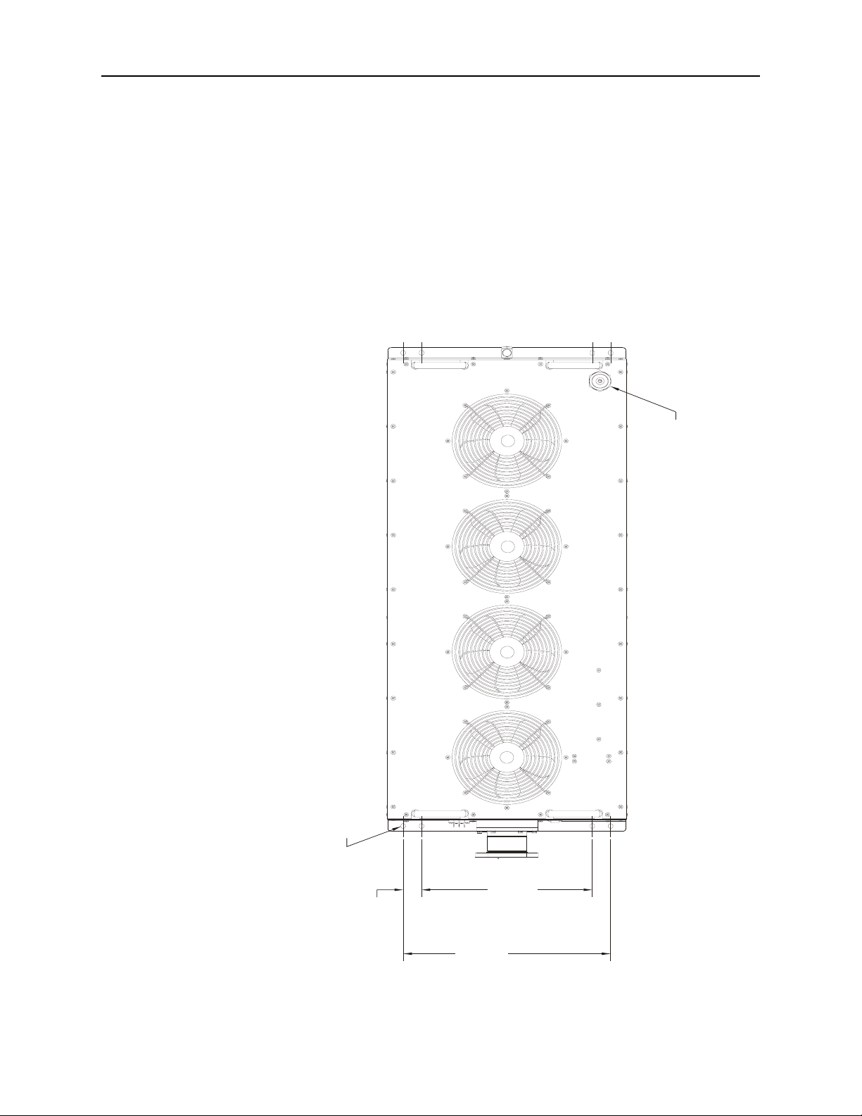
Figure 1 Top View, All Models
Mounting Holes (8)
1-1/2
(38mm)
Filler and Vent Plug
14"
(356mm)
17" ±1/64
(432 ±.4mm)
2
Page 15

Figure 2 Side View, Models 8655B and 8656B
(
Figure 3 End View, All Models
Air
Flow
19-9/16 Nominal
(497mm)
Introduction
Air
Flow
MODEL
WATTS 50,000 OHMS 50
FREQUENCY RANGE 1KHz-.9GHz
AC LINE SUPPLY 115 VOLTS
1 PHASE 60 Hz 14 AMPS
INTERLOCK
9-25/32
(248mm)
CAUTION
AC ON
1-21/32
(42mm)
REF.
9-25/32
(248mm)
19-1/32
(483mm)
Nominal
115 VAC
60 Hz
Air
Flow
3
3
Page 16

Bird 8650 Series Moduload RF Load Resistor
4
Page 17

Chapter 2 Theory of Operation
The Econoload Load Resistor is unique in having its coolant flow over the
outer surface of the substrate. This eliminates the need for an intermediate
heat transfer system thus reducing the load size to a minimum.
Heat Transfer
The 50 ohm resistor consists of a substrate coated with resistive film. The heat
generated by absorption of RF power is transferred from the film to the coolant flowing over it and through a restricted chamber surrounding the resistor
body. This coolant passes over the entire length of the resistor and is cooled in
the forced air heat exchanger.
Interlock
Dissipation of the heat generated by RF power is critically dependent on a
minimum coolant flow of eight gallons per minute at all times, regardless of
coolant temperature. If coolant flow drops below a preset value, the pressure
switch opens and immediately causes the transmitter to shutdown. The pressure switch is a “normally open” type (i.e., its electrical contacts open when
deactivated), and are closed during normal operation.
After coolant flow is restored, a time delay relay keeps the interlock open for an
additional 2 seconds. This ensures proper operation of the cooling system before
RF power is applied to the load thus preventing resistor damage or burnout.
The interlock circuit also contains a temperature switch to monitor the coolant temperature. This switch is normally closed. It will only open if the system
becomes too hot to adequately cool the load. Once the system cools, the switch
closes. Though, as with the pressure switch, the time delay relay impedes the
closure of the interlock contacts for two seconds.
Flow Interlock Control Circuit
The interlock control circuit provides instantaneous fail-safe protection of the
transmitter and load in the event of even momentary interruption of the cooling water supply. This protection is necessary because dissipation of the heat
generated by the RF power is critically dependent upon a required minimum
water supply at all times regardless of system water temperature.
Do not attempt to alter the pressure switch setting or disturb the coolant pump.
The water pressure switch, installed on the RF load’s water input is a “normally open” type; (i.e., its electrical contacts open when deactivated). Closed
during equipment operation, the switch is adjusted to open whenever water
pressure drops below the safe flow level for the specific unit. When this occurs,
the time delay relay is instantly deactivated, thereby opening the interlock
circuit and causing immediate transmitter shutdown.
Also, the centrifugal impeller of the water pump is carefully selected for the
necessary flow rate. The proper operation of this equipment depends on these
conditions being maintained.
CAUTION
5
Page 18

Bird 8650 Series Moduload RF Load Resistor
After coolant flow is restored, the time delay relay keeps the interlock switch
open for a predetermined interval (normally set at about 2 seconds). This
ensures proper operation of the cooling system before RF power is applied to
the load thus preventing resistor damage or burnout.
Figure 4 System Block Diagram
Heat Exchanger
Fan
Pressure
Sensor
Heat Exchanger
Heat Exchanger
Heat Exchanger
Fan
Fan
Fan
6
Page 19

Chapter 3 Installation
Environmental Requirements
These loads are not intended for use outdoors where they would be exposed to
the elements. They should be used indoors in a clean, dry, dust and vibrationfree environment. The ambient temperature range is determined by the coolant. For details of the temperature ranges refer to the specifications. It is
important that the room temperature remain within these limits for proper
operation of the unit, otherwise a derating of the load value will be necessary.
The Model 8655B/56B Moduload is to be installed and operated in a horizontal
position. The unit is shipped horizontal, and normally stands on its attached
base brackets.
WARNING
Do not attempt to handle or move this unit alone. More than one person is
needed to move this unit to avoid possible injury.
For installation of the equipment, mounting angle brackets are attached to the
front and back edges of the enclosure. They may be removed by unscrewing the
four 8-32 Phillips Truss head screws holding each bracket. These brackets have
two elongated holes each on 17 inch by 49-1/2 inch (432 x 1257 mm) centers to
accommodate four 1/4 inch screws that may used for mounting the unit.
The load can be operated anywhere that adequate AC line power, and ventilation are available. Ensure the ambient temperatures do not exceed those
given in the specifications.
Interlock Connections
A terminal strip provides connection to the transmitter’s internal safety interlock circuitry. An active interlock state occurs as a result of either high coolant
temperature or no coolant flow. It will also be active for almost two seconds
after power up.
Interlock connections are made to the terminal strip on the front of the unit.
Connect the interlock wires to the interlock terminal strip as required for the
transmitter in use.
Note: Since 50 kW is equivalent to 170,650 BTU/h, a sufficient
quantity of air must be provided. Allow room for unobstructed air
intake over the whole surface of the grilles, on both sides of the equipment, and a clearance of at least three feet over the top of the unit.
Note: Use number 22 AWG (or heavier) wire for interlock connections.
7
Page 20

Bird 8650 Series Moduload RF Load Resistor
40
0
AC Line Attachment
Before any RF operation of the load is attempted, the transmitter interlock
and AC line attachment to the equipment must be made. First attach the
transmitter interlock connections to the two binding posts on the front
The 115 VAC or 230 VAC line may be connected, but the AC power must not
be turned on unless coolant is in the system and filled to the correct level.
The AC power supply may either be 115V or 240V depending on the unit requirements. AC line power is supplied to the 3-wire AC panel module socket by means
of the 10 foot (3.05 m) cable and matching socket that is furnished with the equipment. The third wire in the cable, coded green/yellow, is the ground wire.
Note: For proper protection, if a 3-wire type plug and outlet is not
used, fasten the green/yellow wire at the supply end to a satisfactory
ground.
Before applying AC power to the unit, make sure:
z Coolant is in the system.
z Coolant is filled to the correct level.
z The green/yellow wire at the supply end is properly grounded.
CAUTION
panel and then connect the power cable.
CAUTION
Damage to the pump will result otherwise.
Figure 5 Freezing Point of Ethylene Glycol /Water Mixture °F
20
0
-20
-40
Specifications for ethylene glycol
Temperature, Degrees Fahrenheit
-60
having: specific gravity 1.125 @
32°F; specific heat .575 @ 68°F
-80
10 20 30 40 50 6
% Ethylene Glycol
8
Page 21

Coolant
Figure 6 Freezing Point of Ethylene Glycol /Water Mixture °C
0
-10
-20
-30
-40
Temperature, Degrees Celsius
Specifications for ethylene glycol
-50
having: specific gravity 1.125 @
32°F; specific heat .575 @ 68°F
-60
10 20 30 40 50 60
% Ethylene Glycol
Installation
Before shipment, the Moduload is drained of coolant to avoid possible damage
from freezing in transit. The system must be refilled with coolant before it can
be put into operation. The unit operates with 17 quarts (16.1 liters) of coolant.
The load’s electrical and thermal performance can become impaired by impurities or additives in the coolant. Impurities which accumulate as scale on the
resistor surface are especially damaging.
The coolant must be either; distilled water or a mixture of distilled water and
ethylene glycol. Distilled water is the primary coolant for the Bird 8650. Ethylene glycol should be added to prevent bacterial growth and freezing.
Note: 10% – 35% ethylene glycol is recommended. Using at least
10% will prevent bacteria growth and 35% will protect against freezing
to –20°C. Table 5 and Table 6 show the coolant’s freezing point for a
given percentage of ethylene glycol in the mix.
To ensure proper mixing add the water first, then the ethylene glycol
WARNING
Ethylene glycol is toxic. Do not take internally. Avoid contact with eyes,
skin, and clothing. Avoid breathing vapor. Wash thoroughly after handling.
CAUTION
Use only distilled water or the supplied ethylene glycol as coolant. Do not
use tap water, automotive antifreeze, sealants, or leak stopping material.
Use of these materials will damage the instrument and void all warranties.
The following example shows the weights to make a 65% distilled water to 35%
ethylene glycol mixture in 5 and 55 gallon quantities:
Distilled Water
Ethylene Glycol
5 Gal. (18.9 L) 55 Gal. (208.2 L)
28.0 lb (12.7 kg) 310 lb (140.6 kg)
15.2 lb (6.9 kg) 167 lb (75.7 kg)
9
Page 22

Bird 8650 Series Moduload RF Load Resistor
Filling the Coolant Reservoir
Note: The Bird 8650R has a coolant capacity of about 17 quarts
(16.1 liters).
1. Ensure the drain plug is in place and that the hose connections are correct
and properly tightened.
2. Remove the filler cap located on the unit’s top.
3. Add about 6 quarts (5.7 liters) of coolant.
4. Replace the filler cap.
5. Turn on the motor, for only a few seconds, to pull the liquid into the
system and draw the coolant level down to the bottom of the tank.
Note: Do not run the pump too long, as partially dry operation
may damage its mechanism.
Note: A convent method is to watch the coolant level through the
reservoir filler. Stop the pump when the coolant level approaches the
bottom of the tank.
6. Repeat Steps 1 to 5 twice more, with about 5.5 quarts (5.2 liters) each
time, or until the fluid remains steady at the proper level.
Note: The unit should be full to a level of about 4-5/8 inches (117
mm) below the top face of the filler tube opening, or to the high mark on
the gauge. Add coolant if necessary to bring to the required level.
7. Run the unit for about five minutes to remove any trapped air in the system.
8. Recheck the fluid level before applying RF power.
Note: The filler plug is equipped with a breather vent to relieve
internal pressure caused by the heated coolant. It is normally closed,
but is set to open at 2 lb/in
Introducing contaminates from unsuitable coolant liquids could coat the cooling system components, particularly the resistor surface. This would unfavorably affect the thermal performance and VSWR of the load. When this is
suspected always check the VSWR. General scale accumulation is not likely
unless the load resistor is used outside the unit and with an improper water
supply. If the coolant system has been contaminated, flush it out. See “Flushing the System” on page 18.
CAUTION
Operation without sufficient coolant can damage the unit.
2
.
Blower Fans
10
The fans are wired direct to the AC line and, when activated, operate along with
the pump.In addition to the basic function of producing the required air flow
through the radiators, this ventilation also aids in cooling the pump/motor unit.
Page 23

Connecting RF Power To Load
Connect the coaxial RF transmission line to the unit. For the respective Models 8655B/56B the connections are as follows.
Model 8655B (3-1/8 inch EIA, 50 ohm, swivel flanged)
Note: Use the 3-1/8" EIA Coupling Kit (p/n 4600-020), which
includes six 3/8-16 x 1-1/2" bolt and nut sets, O-Ring, and insulated
center bullet.
1. Insert the center bullet and push into the seat insulator in the facing.
2. Install the O-Ring into the groove, if required.
3. Connect the coaxial input in a straight line and push carefully on the center contact to close.
Note: The swivel flange on the load makes connection independent
of a fixed flange on coaxial input line.
4. Insert the bolt sets around the flange connection and tighten evenly.
Figure 7 Model 8655B Coupling Kit
RF Coaxial Line 3/8-16 x 1-1/2 Bolt Bullet RF Load Connector
Installation
Model 8656B (3-1/8 inch unflanged, 50 ohm impedance)
Note: Use the Bird Coupling Kit P/N 5-726, consisting of two
clamping bands, an outer sleeve, and the center coupling bullet.
1. Insert the center bullet, and bottom it on the midpoint nibs.
2. Position the outer sleeve, with clamps, over the input connector.
3. Seat the transmission line snugly against the coupling stops.
4. Position the clamp bands evenly about 3-3/4 inches apart, and tighten.
Figure 8 Model 8656B Coupling Kit
RF Coaxial Line Clamping Bands Connector Sleeve Bullet RF Load Connector
Preliminary Equipment Check
Check the RF load for acceptable electrical condition. See “Measuring DC
Resistance” on page 16.
11
Page 24

Bird 8650 Series Moduload RF Load Resistor
Meter Rack
The Meter Rack is used to hold the meter at the correct angle, for the best possible viewing.
1. Assemble the rack using four #6-32 x 3/8 screws.
2. Remove the two screws from the panel at a desired mounting location.
3. Mount the assembled Meter Rack using #8-32 x 3/8 phillips truss head screws.
Figure 9 Meter Rack Assembly
12
Page 25

Chapter 4 Operating Instructions
CAUTION
Do not operate the load without proper coolant levels. Operation without sufficient
coolant can damage the unit.
Use and Function of Controls
The Models 8655B and 8656B loads have no operating controls, other than the
ON/OFF switch; therefore, they do not require an operator in attendance.
Initial Adjustments and Control Settings
There are no adjustments or settings required beyond confirming that the
cooling system contains an adequate level of coolant for proper operation. See
“Coolant” on page 9.
Equipment Startup
CAUTION
Do not operate the load without connecting the interlock. Even momentary
application of power to the load while the cooling circulation is off, or
possibly functioning improperly, will cause almost immediate destruction of
the resistor element.
CAUTION
Do not apply more than the rated RF power to the load. Excessive RF power
will damage the load resistor.
CAUTION
Do not block air flow. Air enters the housing through the grille openings and
exhausts through the circular fan openings.
1. Ensure the coolant level is adequate. See “Coolant” on page 9.
2. Verify fan operation. See “Blower Fans” on page 10.
3. Turn interlock supply on.
4. Turn on 115V or 230V power.
5. Apply RF to the load.
13
Page 26

Bird 8650 Series Moduload RF Load Resistor
Normal Shutdown
Do not disconnect the line power first. Even a momentary application of RF
power to the load while the cooling circulation is off will cause almost
1. Turn RF power to the load off.
2. Wait five minutes, allowing the pump and fans to return coolant to ambient
room temperature.
3. Turn AC power off.
Note: Stopping the pump automatically opens the interlock connection.
Emergency Shutdown
With the use of interlock capability, the Load will automatically turn off the
transmitter’s RF power if an emergency arises.
CAUTION
immediate destruction of the resistor element.
Performance Notes
Should an emergency arise that is not a fault of the unit, always turn off the
source of RF power first, and then the AC power to the load.
The electrical performance of the Model 8655B/56B RF Loads is affected by
impurities or other chemical additives in the cooling liquid. Therefore, the
cooling liquid should be distilled water, or distilled water with industrially
pure ethylene glycol. Do not use any additives
Thermal performance is affected by impurities, particularly those which accumulate in the form of scale on the surface of the ceramic tube and any other
water passages. This results in an increase of thermal resistance of the load,
and in turn, may cause the load to overheat and fail.
Used in conjunction with the appropriate Bird model wattmeter, such as the
Series 4600 and 4800 Thruline Wattmeter, the Model 8655B/56B may will be
capable of direct reading of RF power measurements within the equipment.s
rating.
14
Page 27

Chapter 5 Maintenance
Troubleshooting
The table below contains troubleshooting information for problems which can
occur during normal operation. Locate the problem, review the possible cause,
and perform the action listed.
Problem Possible Cause Correction
.
Transmitter
will not come
on
or
Shuts off
repeatedly.
Excessive
reflected
power
Coolant
leaking
New or
unusual
noises.
Burnt out
resistor
Insufficient coolant flow. Check coolant gauge.
Check for blockage in circulatory system.
Check for coolant leaks.
Defective flow switch Check flow switch.
Defective pump Check pump.
Overheating Check for sufficient coolant.
Defective thermoswitch Check thermoswitch.
Check for excessive room temperature.
Check fans for jamming and grilles for
blockage.
Damaged resistor Check resistance value of RF section.
Contaminated coolant Drain, flush, and refill coolant system.
See “Flushing the System” on page 18.
Insufficient coolant Check for coolant leaks and add more
coolant.
Loose connections Check and tighten all connections.
Worn or cracked tubing Replace defective tubing.
Fans Check for loose fan blades.
Pump Check pump for signs of failure.
Circulatory system Check for any sign of coolant leakage.
Transmitter not connected
to interlock terminals.
Follow installation procedure. See
“Installation” on page 7.
Moduload will
not come on.
RF power overload Reduce power output from transmitter.
Check over-temperature thermo-switch.
No line power Check AC power source and power cord.
Fuses burned out Replace fuses. Check for cause. See
“Replacing the Fuse” on page 22.
Defective switch Replace switch. See “Replacing the
Water Pressure Switch” on page 21.
15
Page 28

Bird 8650 Series Moduload RF Load Resistor
RF Load Resistor
Measuring DC Resistance
Accurate measurement of the DC resistance between the inner and outer conductors of the RF input connector will provide a good check of the condition of
the load resistor. Checking the DC resistance measures changes in the condition of the resistor over time. Tracking the DC resistance must start before the
resistor is first put into service.
z Equipment Needed:
z Common hand tools
z Ohmmeter with an accuracy of ±1% at 50 ohms
Note: Temperature of the load needs to be between 20°C to 25°C
(68°F to 77°F).
Never attempt to connect or disconnect an RF transmission line while
power is on at the RF power source. Radiated RF energy is a potential
WARNING
health hazard.
1. Turn off RF power and interlock circuitry before making any electrical disconnections.
2. Disconnect RF coaxial line.
3. Connect the multimeter test leads to the load resistor:
z One lead to the center conductor.
z One lead to the outer conductor.
4. Record the value of the resistance before the load is put into service.
5. Compare subsequent values with the latest reading.
Note: If the values vary more than 2 ohms this could be an indica-
tion of a failing resistive element.
Note: It is recommended that this resistance check be performed
each time the load is to be used.
Figure 10 Measuring DC Resistance
16
Page 29

Routine Service Checks
Cleaning
Maintenance
Inspecting the Coolant
Inspect the coolant level at regular intervals, when the equipment is in use.
Normally check once or twice a week, more often if it is used continuously or
under high ambient temperatures. The coolant level should remain at the
upper gauge mark on the back panel, whether the unit is running or not. For
test measurement and addition of liquid if required, see “Coolant” on page 9.
Inspecting the External Surface
The radiator surface, particularly on the inside, should be checked periodically for possible collection of dust and lint. A heavy lint coating on the inside
surface of the radiator can impair the cooling efficiency of the unit. Follow the
instructions below for cleaning. See “Cleaning”.
The most important cleaning task is to remove accumulations of dust, lint,
and grime that could interfere with proper air circulation and therefore efficient heat transfer. The heat exchanger surfaces, particularly on the inside,
should be checked periodically for possible collection of dust and lint.
z Equipment Needed:
z Lint-free cleaning cloth
z Mild detergent
Cleaning the Instrument Housing and Panels
1. Remove loose dirt and grime, gently, using a soft clean cloth dampened
with a warm solution of mild detergent and water.
Note: A vacuum can be used to clean the radiators if necessary.
2. Remove the 26 screws from the top panel to gain access to the radiators.
3. Clean off dust and lint, if any, with a radiator brush or stiff bristle brush.
4. Check under the ribs of the air intake grille (at the side) for dust collection. If there is a buildup, remove the grille and clean under the ribs.
5. Replace top panel and screws.
Note: Heavy coatings of lint on any surfaces of the heat exchanger
unit can impair the efficiency of the Moduload unit. Keep them clean.
Cleaning the Connector and Outside Surface
Note: Use a soft, clean cloth dampened with mild detergent.
z Wipe dust and dirt from the outside surface of the unit
Note: zThis should be performed at regular intervals.
z Check the condition of the RF coaxial connector.
z Clean the RF input connector, If needed, use a self-drying contact
cleaner that leaves no residue.
17
Page 30

Bird 8650 Series Moduload RF Load Resistor
Flushing the System
Whenever maintenance work has been performed, including resistor repair, or
there is a reason to suspect that contamination has been introduced or dislodged into the coolant, the system should be thoroughly flushed.
Disconnect from RF power sources and the AC line before any disassembly
Incorrect hose connections will reverse coolant flow and could destroy the load.
1. Run the load with coolant but without RF power applied for a period of
three to five minutes.
2. Drain the circulating system as completely as possible.
3. Fill the unit with fresh, clean, distilled water.
4. Repeat steps 1 - 3 until the drained liquid is clear.
5. Fill the unit with distilled water and/or approved ethylene glycol mixture.
See “Coolant” on page 9.
Note: If the unit is to remain fully or partially drained for two
weeks or more, see “Storage” on page 28.
WARNING
or service. Electrical shock hazard.
CAUTION
Repair and Replacement Procedures
Disconnect from RF power sources and the AC line before any disassembly
Improper wiring could result in electric shock and death.
The 8655B/56B Moduload Load Resistor is designed for independent, long term,
trouble-free operation. Regular mechanical maintenance procedures, other than
routine checks and cleaning care described previously, are not required. In the
case of malfunction of the unit or replacement of a major component, resistor
repair excepted, the entire load may be returned to the factory. This applies
especially to any unit under the one year warranty. Consult the factory.
Note: Do not tamper with operational settings or perform other
unauthorized maintenance work during the first year. It could be cause
to void the warranty.
Field repair of the load resistor may be performed as described in the Load
Resistor Internal Repair paragraph. Other replacement instructions, that
might be needed, are given in this section.
If in performing the DC resistance check a significant change in resistance is
noted, or if for any reason the resistive element should fail, the element
should be replaced. Replacement resistors are available.
WARNING
or service. Electrical shock hazard.
WARNING
18
Page 31

RF Load Assembly
Maintenance
Removing the RF Load
Note: The full load assembly may be removed from the case as in
the following procedure.
Note: Resistor repair in the load may be done without removing
the water connections; see “Load Resistor Internal Repair” on page 23.
Note: Notice the angular position of all elbows and associated
parts as they must be returned to relatively the same position when
reassembled.
z Equipment Needed:
z
Common hand tools
WARNING
Never attempt to connect or disconnect an RF transmission line while
power is on at the RF power source. Radiated RF energy is a potential
health hazard.
1. Turn off RF power and interlock circuitry before any electrical disconnections are made.
2. Disconnect the RF coaxial line.
3. Remove the 3/8-16 bolt and nut sets that secure the flanges.
4. Separate the transmission coaxial air line from the load connector.
Note: Make sure the center conductor bullet remains in the trans-
mission line.
5. Take off the top panel by removing the 26 screws around its perimeter.
6. Turn all four handles outward and slightly lift up the top panel assembly.
7. Reach under the top panel and press the connector latch of the fan power
cable.
Note: This will disconnect the small fan-supply plug from its mat-
ing connector seated on top of the radiator block.
8. Unscrew the drain plug located at the bottom center of the rear panel.
9. Allow the coolant to drain.
Note: Do not replace the drain plug with any substitute plug, use
the plug removed.
10. Unscrew both hose clamps on the water connections to the load resistor.
Note: The water inlet is through the pressure switch tee fitting at
the back of the load. The water outlet is located on the lower side of the
load.
11. Disconnect the orange wire and black wire from the pressure switch
(located at the load input).
12. Disconnect the black, white, and greens wires from the pump power cable
located at the terminal block on the inside of the front panel.
13. Disconnect the six-pin front panel connector located at the in-line connector on the top of the radiator bracket near the front panel.
19
Page 32

Bird 8650 Series Moduload RF Load Resistor
14. Remove the two 5/16 hex head screws from the load clamp.
15. Remove the upper half of the load clamp from the load.
16. Remove the 16 screws that secure the perimeter of the front panel.
17. Remove the front panel with the load attached.
18. Remove the nuts and lock-washers that secure the load to the front panel.
19. Remove the socket hard cap screws that secure the water chamber to the
load.
20. Remove the water chamber.
Note: After the water chamber has been removed, the front panel
can be removed from the load.
21. Do one of the following:
z If servicing the load, see “Load Resistor Internal Repair” on page 23.
z If not servicing the load, replace the water chamber and its mounting
hardware and return the load to the factory of service.
22. Replace the load resistor by careful reversal of the above procedure.
Note: Be sure to replace the coolant per the coolant section. Check
for leaks, especially at the restored connections. See “Coolant” on page 9.
Pump/Motor Removal
Note: For removal and replacement of the pump/motor proceed as
follows.
Note: The back panel of the Moduload housing may have to be
taken off to remove the pump/motor unit.
1. Take off the top panel by removing the 26 screws around its perimeter.
2. Turn all four handles outward and slightly lift up the top panel assembly.
3. Reach under the top panel and press the connector latch of the fan power
cable.
Note: This will disconnect the small fan-supply plug from its mat-
ing connector seated on top of the radiator block.
4. Unscrew the drain plug located at the bottom center of the rear panel.
5. Allow the coolant to drain.
Note: Do not replace the drain plug with any substitute plug, use
the plug removed.
6. Detach the three connecting wire leads of the pump power cable from the
three-lug terminal block on the inside of the front panel.
Note: For reference the color codes of the motor supply wires match
the input wires.
7. Loosen the following:
z The hose from the input of the pump.
z The hose from the output on the pump.
8. Remove the four 1/4-20 nuts and lockwashers that secure the pump and
mounting bracket to the isolation mounts on the frame.
Note: Use 9/16 inch wrenches.
9. Move the pump assembly slowly forward while detaching the hoses.
20
Page 33

10. Lift the pump/motor/bracket assembly out of the equipment.
Note: Make note of the fitting positions.
11. Twist off, counterclockwise, the whole parts of the fittings.
Note: Do not disturb the 25° upward tilt of the 90° input elbow.
Note: Store the detached parts with the disassembled unit and return
the pump/motor /bracket assembly to the factory for replacement.
Installing the Pump/Motor Assembly
To install the pump/motor reverse the removal procedures.
Note:
z When installing the pump/motor, make sure the unit is placed so
that the top panel will not hit the top of the unit.
z Coat only the external threads with a pipe sealing compound when
replacing the threaded fittings.
z Coat only the external threads, to avoid pressing the pipe sealing
compound into the cooling system and contaminating the coolant.
z Twist on the threaded fittings, until the treaded joints are tight
and all parts are in their original angular position.
z Rewire to the same terminal block connections.
Maintenance
Replacing the Water Pressure Switch
The water pressure (Safety Control) switch is changed by the same process
that is used for replacing the load resistor.
Perform the following disassembly operations. It is not necessary to fully
remove the load resistor from the unit, or to disturb its output fitting.
z Equipment Needed:
z
Common hand tools
Never attempt to connect or disconnect an RF transmission line while
power is on at the RF power source. Radiated RF energy is a potential
1. Turn off RF power and interlock circuitry before any electrical disconnections are made.
2. Disconnect the RF coaxial line.
3. Remove the 3/8-16 bolt and nut sets that secure the flanges.
4. Separate the transmission coaxial air line from the load connector.
Note: Make sure the center conductor bullet remains in the trans-
mission line.
5. Take off the top panel by removing the 26 screws around its perimeter.
6. Turn all four handles outward and slightly lift up the top panel assembly.
7. Reach under the top panel and press the connector latch of the fan power
cable.
Note: This will disconnect the small fan-supply plug from its mat-
ing connector seated on top of the radiator block.
8. Unscrew the drain plug at the bottom center of the rear panel.
9. Allow the coolant to drain.
WARNING
health hazard.
21
Page 34

Bird 8650 Series Moduload RF Load Resistor
Note: Do not replace the drain plug with any substitute plug, use
the plug removed.
10. Disconnect the orange and black wires from the pressure switch.
Note: The water inlet is through the pressure switch at the back of
the load input nipple.
11. Detach the switch assembly from the load.
Note: The switch is ready for service or replacement.
Note: When replacing the switch fittings be sure to coat only the
external threads with joint sealing compound.
Note: When reinstalling the switch assembly, twist on the compo-
nents until the switch body is in the original angular alignment with
the load resistor housing.
12. Restore the wire connections.
13. Refill the equipment with coolant to the proper level.
14. Check the refitted joints thoroughly.
15. Test the switch operation by a preoperational run, as described in "Coolant"
on page 9, without RF power.
16. Inspect for leaks by running the coolant pump for a few minutes without the
top panel.
Replacing the Time Delay Relay for 8655B and 8656B
The time delay relay is factory set for an approximate two second delay, isolating
the circuit relay. See “Flow Interlock Control Circuit” on page 5.
Note: The relay is located on the upper right inside of the front panel.
Note: The relay cartridge cannot be disassembled or repaired in
the field.
1. Record the color and routing of the wires on each relay terminal.
2. Remove the wires from the relay terminals.
3. Remove the nut and washers that secure the relay to the panel.
4. Remove the relay.
5. Install the replacement relay by reversing Step 2 through Step 4,
Replacing the Fuse
z Equipment Needed:
z
Common hand tools
1. Disconnect AC power line.
2. Lift up on the tab that secures the drawer the AC receptacle.
Note: Use the flat blade of a screwdriver.
3. Pull the drawer straight out.
4. Remove the fuse.
5. Replace with the same type and rating fuse.
6. Return the drawer to the receptacle.
7. Reconnect the AC power line.
8. Check the unit for proper operation.
22
Page 35

Load Resistor Internal Repair
The water cooled load used in the Moduload is designed to be quickly and easily repaired in the field. If in performing the DC resistance check ("Measuring
DC Resistance" on page 16), significant changes in resistance are noticed or if
for any reason the resistive element should fail, replacement resistors are
available. See “Replacement Parts List” on page 31.
Removing the Resistor Main Housing
Removing the Resistor
Note: The inner flow tube will usually come out with the water
chamber assembly being held to it by the compression of the inner ORing water input seal. This is normal and if the resistor body is unbroken there will be no need to remove the inner flow tube from the water
chamber assembly.
Note: The ground cap assembly is fitted tightly within the water
chamber and should normally remain with it. If the ground cap is still
on the end of the resistor, remove it before proceeding.
1. Do one of the following:
z If the inner flow tube has stayed in the resistor section:
a. Grasp the resistor stop sleeve on the flow tube.
b. Pull out the assembly.
Note: This includes the cushioning O-Ring which fits loosely
below the stop sleeve.
Note: Do not lose the O-Ring.
z If the brass resistor sleeve is removed:
Notice that it has a small escape hole at the side, and an access counterbore leading to it.
Note: In reassembly, be sure this counterbore is facing toward the O-
Ring and the resistor. It is necessary for internal water venting. The water
outlet holes, and also the small shoulder at the base of the inner flow tube,
must fit into the mating recess in the input fitting at the bottom.
z If the resistor is intact:
a. Pull it straight out of the load housing.
Note: The outer flow tube is captive and will not come out of
the housing at this stage.
Inspecting the Resistor
Maintenance
If the resistor has been successfully removed, inspect it to make sure it has
not been fractured. In most cases, even in the event of a resistor failure, the
resistor substrate will remain intact. Also, examine the inside of the load
housing assembly for any visible damage to the internal parts.
If no damage is found, continue with Resistor Replacement.
If the resistor is broken, other internal parts appear to be damaged, or if they
do not fit together properly, proceed to Replacement Procedure for Fractured
Resistors.
23
Page 36

Bird 8650 Series Moduload RF Load Resistor
Replacing the Resistor
Note: Use this section only if there has been no damage done to the
resistors or other internal parts of the load.
1. Insert the new resistor into the load housing until it reaches the resistor
fitting.
2. Rotate, and rock, carefully, the resistor until it starts to enter its way into
the resistor fitting.
3. Push the resistor into the fitting until it bottoms on the spacer ring.
4. Ensure the spacer ring is in the proper place.
Note: If the resistor seems to be loose, refer to the procedure for the
replacement of fractured resistors or damaged internal parts. That section has instructions on how to tighten the resistor fitting.
5. Do one of the following:
z If damaged:
a. Replace the inner flow tube.
z If undamaged:
a. Place the original flow tube inside the resistor.
b. Lower it until it reaches the resistor fitting.
c. Gently work and twist the inner flow tube until it seats in the bot-
6. Slide the back-up resistor sleeve and O-Ring down the inner flow tube
until it rests on the end of the resistor.
Note: There is no need to disturb the resistor cap assembly in the
water chamber for this procedure. If the ground cap has been removed,
replace it on the end of the resistor before continuing.
7. Install the water chamber gently rocking and twisting the chamber to
achieve the proper flat seat on the outer housing.
Note: If the water chamber does not seem to fit properly, refer back
to step 3 to make sure the inner flow tube is properly in place.
8. Place the resistor housing through the front panel opening, and into the
water chamber.
9. Turn the housing, gently, clockwise to thread it on, eventually bottoming
it in its original position.
10. Reverse "Removing the RF Load" on page 19.
Note: Do not replace the top panel until after this section is com-
pleted.
11. Check the DC resistance between the outer and inner conductors; it
should be approximately 50 ohms. See “Measuring DC Resistance” on
page 16, and Figure 10 on page 16.
12. If the resistance check passes, flush out. See “Flushing the System” on page 18.
13. Inspect for leaks by running the coolant pump for a few minutes without the
top panel.
Note: After the completion of this or any of the resistor repair pro-
cedures, run the pump/motor for five minutes and check thoroughly for
leaks before applying RF power to the load.
14. Install the top panel.
tom of the resistor fitting.
Note: This operation may also be done if the inner flow tube is
still in position in the water chamber when the main housing is
being reinstalled.
24
Page 37

Replacing Fractured Resistors or Damaged Internal Parts
Removing Resistor
Note: Refer to Figure 11 on page 26 for this procedure.
1. Turn the load on end, with the RF input connector up, to allow debris, if
present, to fall out of the load housing.
2. Remove the 1/4-20 x 1-1/2 inch socket head screws from the flanged end of
the load housing assembly, as shown in Figure 11.
3. Remove the outer conductor assembly.
4. Remove the input center conductor assembly by pulling it out of the housing.
5. Remove any remaining pieces of the resistor.
Note: Normally, in the disassembly, the outer flow tube will
remain with the load housing. Restore it to that position after inspection and cleaning if it should come out.
6. Inspect the inside of the load housing for damage.
7. Pull the inner flow tube from the water chamber.
8. Inspect carefully for broken pieces.
9. Grasp the projecting hub of the ground cap assembly firmly and pull it
straight off with a strong even force.
10. Wash all the inside portions of the three assemblies; input section, load
housing, and water chamber, thoroughly with distilled water.
11. Inspect all O-rings for damage before reassembling the load.
Installing the Resistor
1. Test the tightness of the replacement resistor by inserting it into the fitting of the input center conductor assembly.
Note: The resistor should not have to be forced into the fitting, but
should be quite snug.
2. Do one of the following:
z If the fitting is loose in the fitting, press the slotted finger contacts
together slightly and try the resistor again.
Note: Continue this procedure until a snug fit is obtained.
z If the fitting is snug, proceed to Step 3.
3. Bottom the resistor in the fitting.
4. Insert the resistor, and the input center conductor assembly, into the load
housing with the resistor still in place in the fitting.
5. Secure the outer conductor assembly with the six 1/4-20 x 1-1/2 inch
socket head cap screws.
Assembling the Unit
1. Stand the load on its end with the RF input connector down.
2. Place the inner flow tube inside the resistor and lower it until it reaches
the resistor fitting.
3. Gently move and twist the inner flow tube until it seats in the bottom of
the resistor fitting.
Assembling the Front Connector
1. Remove the six screws at the front of the housing to release the conductors.
2. Change the O-Ring seal to the outer water flow tube once the inner conductor has been pulled out
CAUTION
Do not attempt further disassembly of this part.
Maintenance
25
Page 38

Bird 8650 Series Moduload RF Load Resistor
3. If necessary, return the part to the factory for repair.
4. Replace the ground cap assembly on the exposed end of the resistor as
shown in Figure 10.
5. Replace the O-ring and resistor sleeve.
Note: The counterbore faces toward the O-Ring and the resistor. It
is necessary for internal water venting. The water outlet holes, and also
the small shoulder at the base of the inner flow tube, must fit into the
mating recess in the input fitting at the bottom.
6. Replace the front panel on the load then replace the water chamber and 1/
4-20 socket head cap screws.
7. Reassemble the load into the heat exchanger assembly. Reverse "Removing the RF Load" on page 19.
Figure 11 Removing the Resistor
6
1/4-20 x 2-1/2
Socket Head Cap Screw (6)
5A
Hose Fitting Straight
4
3
and
Water Chamb er W ith
O-Ring Inner Seal
2
Outer O-Ring
17
Inner O-Ring
7
Resistor Sleeve
1
Resistor
9A
Outer Flow Tube
5
Hose Fitting 90°
10
Ground Cap Assembly
9
Inner Flow Tube
8
O-Ring
Load Housing
26
Page 39

Figure 12 Removing the Connector
12
Outer Conductor
Assembly
16
1/4-20 x 1-1/2
Socket Head Cap Screw (6)
Maintenance
11
Center Conductor
Assembly
15
Resistor Fitting Seal O-Ring
1
Resistor
Load Housing
27
Page 40

Bird 8650 Series Moduload RF Load Resistor
Storage
Failure to follow the special storage instructions may result in damage to
If the unit is to be stored it should be stored filled with coolant if possible. If
storing the unit filled is not possible, consult the factory for special instructions.
Drainage
If the unit is to be stored partly drained or fully drained for two weeks or longer, consult the factory for special instructions.
Shipment
Failure to properly prepare the unit for shipment using the special storage
instructions may result in damage to the unit. Consult the factory for the
CAUTION
the unit. Consult the factory for the special instructions.
CAUTION
special instructions.
If the unit is to be shipped, prepare the unit for shipping using the special
storage instructions for Moduloads.
28
Page 41

Customer Service
Maintenance
Any maintenance or service procedure beyond the scope of those in this chapter should be referred to a qualified service center.
If the unit needs to be returned for any reason, request an RMA through the
Bird Technologies website. All instruments returned must be shipped prepaid
and to the attention of the RMA number.
Bird Service Center
30303 Aurora Road
Cleveland (Solon), Ohio 44139-2794
Fax: (440) 248-5426
E-mail: bsc@bird-technologies.com
For the location of the Sales Office nearest you, visit our Web site at:
http://www.bird-technologies.com
29
Page 42

Bird 8650 Series Moduload RF Load Resistor
Specifications
Impedance, Nominal 50 ohms
Power Rating, Max 50 kW
Frequency Range 1 kHz - 900 MHz
Connector
Model 8655-( )
Model 8656-( )
VSWR 1.10:1
Modes CW, AM, FM, TV, SSB, and certain pulse
1 -115-6 added for 115 V 60 Hz -230-5 added for 230 V 50 Hz-230-6 added for
230 V 60 Hz
Econoload
1
1
3-1/8" EIA Flanged
3-1/8" Unflanged (flush center conductor)
types
System
Ambient Temperature See Table 2-1.
AC Power Required 115 VAC @ 15 Amps, 50/60 Hz
230 VAC @ 8 Amps, 50/60 Hz
Dimensions, Nominal 19-1/32"H x 19-9/16"W x 44-1/4"L without
connector (483 x 497 x 1124 mm)
2
Coolant 17 qts (16 liters) distilled water
ethylene glycol mixture
2
or 35%
Weight, Nominal 275 lbs (124.7 kg)
Finish Grey Powder Coat
Table 2-1 Bird 8650 Series Ambient Temp. vs. Max. RF Power
Coolant
1
35% E.G.
45°C NA 40.0 kW
35°C 40.0 kW 40.0 kW
30°C 40.0 kW 50.0 kW
5 to 25°C 50.0 kW 50.0 kW
–20 to 5°C 50.0 kW NA
1 Below 5°C, ONLY use 35% E.G. and 65% Dist. H2O mixture
100% Dist. H
O
2
30
Page 43

Replacement Parts List
Models 8655B and 8656B
Item Qty. Description Part Number
Maintenance
1 1 RF Load Resistor (Econoload):
2 1 Switch, Rocker 5A2384
3 1 AC Connector (Fuse Casing) 5-1844
4 1 Line Cord:
7 1 Relay, Time Delay 5A2787-1
10 1 Thermoswitch (79°C) 5A2788-1
12 1 Coolant tank Assy. 8650B030
13 1 Terminal strip assembly 8640-682
14 1 Pump/Motor/Bracket Assembly:
15 1 Drain Plug 8640-036
16 4 Handle - 90°, 2 position 5-882
17 1 Coolant gauge (replacement kit) 5-1200
18 1 Ethylene Glycol coolant 5-1134-3
19 1 Fuse Drawer
20
1
2
* Load resistors installed per models listed in specifications.
Model 8655
Model 8656
115V
230V
230V 60Hz
115V 50Hz
230V 50Hz
115V 60Hz
115 VAC
230 VAC
Fuse
115 VAC (3AB Time Delay 15 amp 250V)
230 VAC (5x20, Time Delay, 8 amp, 250V)
Fan
864-5-115 (115 VAC)
864-5-230 (230 VAC)
Fan panel assembly (includes fans, panel, wiring)
115 VAC
230 VAC
8775-100*
8776-100*
5-1836
5-1837
RPK8650-60-230
RPK8650-50-115
RPK8650-50-230
RPK8650-60-115
5-1845-FD
5A2310
5-1828-36
5A2257-25
5A2770-1
5A2770-2
8650B003-1
8650B003-2
31
Page 44

Bird 8650 Series Moduload RF Load Resistor
Models 8775-100 and 8776-100 Load resistor for Moduload 8655B/56B Units
Item Qty. Description Part Number
1 1 Resistor 8755-027-5
2 1 Outer resistor cap seal O-Ring 8410-009
3 1 Water Chamber 8755-014
4 1 O-Ring Inner Seal 5-099
5 1 Plumbing assy., Hose Fitting 90° 8650-040
5A 1 Pipe Load Input assy., Hose Fitting Straight,
with space for pressure switch
6 6 Socket Head Cap Screw, 1/4-20 x 2-1/2”
Stainless Steel
7 1 Resistor Sleeve 8755-026
8 1 Sleeve back-up O-Ring 8110-059
9 1 Inner flow tube 8755-025
9A 1 Outer flow tube 8755-024
10 1 Resistor ground cap assembly 8755-005
17 1 Inner resistor cap seal O-Ring 5-567
18 1 R.F. Load Housing Assy. 8755-006
8650-039
1121-2508-00
Front Connector Parts assigned Per Model Type
Model 8655 — 3-1/8” EIA Connector 50 Ohms
Item Qty. Description Part Number
11 1 Center conductor input assembly 8755-007
12 1 Outer conductor assembly 8755-004
Model 8656B — 3-1/8” Unflanged Connector, Flush Center Conductor,
50 Ohms
Item Qty. Description Part Number
11 1 Center conductor input assembly 8756-003
12 1 Outer conductor assembly 8756-002
Both Models, 8655B and 8656B
Item Qty. Description Part Number
15 1 Center conductor assembly O-Ring 5-1127
16 6 Socket Head Cap Screw, 1/4-20 x 1-1/2"
Stainless Steel
1121-1808-00
32
Page 45

Limited Warranty
All products manufactured by Seller are warranted to be free from defects in material and
workmanship for a period of one (1) year, unless otherwise specified, from date of shipment and to conform to applicable specifications, drawings, blueprints and/or samples.
Seller’s sole obligation under these warranties shall be to issue credit, repair or replace
any item or part thereof which is proved to be other than as warranted; no allowance shall
be made for any labor charges of Buyer for replacement of parts, adjustment or repairs, or
any other work, unless such charges are authorized in advance by Seller.
If Seller’s products are claimed to be defective in material or workmanship or not to conform to specifications, drawings, blueprints and/or samples, Seller shall, upon prompt
notice thereof, either examine the products where they are located or issue shipping
instructions for return to Seller (transportation-charges prepaid by Buyer). In the event
any of our products are proved to be other than as warranted, transportation costs (cheapest way) to and from Seller’s plant, will be borne by Seller and reimbursement or credit
will be made for amounts so expended by Buyer. Every such claim for breach of these warranties shall be deemed to be waived by Buyer unless made in writing within ten (10)
days from the date of discovery of the defect.
The above warranties shall not extend to any products or parts thereof which have been
subjected to any misuse or neglect, damaged by accident, rendered defective by reason of
improper installation or by the performance of repairs or alterations outside of our plant,
and shall not apply to any goods or parts thereof furnished by Buyer or acquired from others at Buyer’s request and/or to Buyer’s specifications. Routine (regularly required) calibration is not covered under this limited warranty. In addition, Seller’s warranties do not
extend to the failure of tubes, transistors, fuses and batteries, or to other equipment and
parts manufactured by others except to the extent of the original manufacturer’s warranty to Seller.
The obligations under the foregoing warranties are limited to the precise terms thereof.
These warranties provide exclusive remedies, expressly in lieu of all other remedies
including claims for special or consequential damages. SELLER NEITHER MAKES NOR
ASSUMES ANY OTHER WARRANTY WHAT-SOEVER, WHETHER EXPRESS, STATUTORY, OR IMPLIED, INCLUDING WARRANTIES OF MERCHANTABILITY AND FITNESS, AND NO PERSON IS AUTHORIZED TO ASSUME FOR SELLER ANY
OBLIGATION OR LIABILITY NOT STRICTLY IN ACCORDANCE WITH THE FOREGOING.
 Loading...