

Page 1

INSTRUCTION BOOK
MODULOAD® RF LOAD RESISTOR
SERIES 8640 and 8640B
INCLUDING MODELS 8645-xxx AND 8646-xxx
Bird® Electronic Corporation
30303 Aurora Road
Cleveland (Solon), Ohio 44139
Sales & Technical Support: 440-248-1200
Sales email: sales@bird-technologies.com
Technical Support email: techsupport@bird-technologies.com
Moduload
866-695-4569 toll free
©Copyright 2008 by Bird Electronic Corporation
Instruction Book Part Number 920-8640S Rev. F
®
, Econoload®, Econoline®, and Thruline® are
registered trademarks of Bird Electronic Corporation
Page 2

Safety Precautions
The following are general safety precautions that are not necessarily
related to any specific part or procedure and do not necessarily appear
elsewhere in this publication. These precautions must be thoroughly
understood and applied to all phases of operation and maintenance.
Keep Away From Live Circuits
Operating personnel must at all times observe normal safety regulations.
Do not replace components or make adjustments inside the equipment
with high voltage turned on. To avoid casualties, always remove power.
Shock Hazard
Do not remove the RF transmission line while RF power is present.
Capacitors can store a dangerous electric charge. Avoid contact with all
system capacitors. If it is necessary to perform work near a system
capacitor, be sure to discharge the capacitor through a low resistance.
Do Not Service Or Adjust Alone
Under no circumstances should any personnel reach into an enclosure for
the purpose of service or adjustment of equipment except in the presence
of someone who is capable of rendering aid.
Safety Earth Ground
An uninterruptible earth safety ground must be supplied from the main
power source to test instruments. Grounding one conductor of a two
conductor power cable is not sufficient protection. Serious injury or death
can occur if this grounding is not properly supplied.
Chemical Hazard
Dry cleaning solvents for cleaning parts may be potentially dangerous.
Avoid inhalation of fumes or prolonged contact with skin.
Coolant may contain ethylene glycol. Avoid ingestion, inhaling of vapors
and eye and skin contact.
Resuscitation
Personnel working with or near high voltages should be familiar with
modern methods of resuscitation.
i
Page 3

Bird 8640 and 8640B Series Moduload RF Load Resistor
Safety Symbols
WARNING
Warning notes call attention to a procedure, which if not correctly
performed could result in personal injury.
CAUTION
Caution notes call attention to a procedure, which if not correctly
performed could result in damage to the instrument.
This symbol indicates that a shock hazard exists if the
precautions in the instruction manual are not follwed.
The caution symbol appears on the equipment indicating
there is important information in the instruction manual
regarding that particular area.
NOTE: Calls attention to supplemental information.
Warning Statements
The following safety warnings appear in the text where there is danger to
operating and maintenance personnel and are repeated here for emphasis.
WARNING
Disconnect the unit from all power sources before servicing.
The unit may be energized from multiple sources.
The potential for electric shock exists.
WARNING
Improper wiring could result in electric shock and death.
WARNING
Connect the power cord to the Moduload
BEFORE connecting to ac mains.
WARNING
Ethylene glycol is toxic. Do not take internally.
Avoid contact with eyes, skin, and clothing. Avoid breathing vapor.
Wash thoroughly after handling.
ii
Page 4

WARNING
Never attempt to connect or disconnect RF equipment from the
transmission line while RF power is being applied.
Leaking RF energy is a potential health hazard.
WARNING
HEAVY. Do not lift this unit alone.
Caution Statements
The following equipment cautions appear in the text whenever the
equipment is in danger of damage and are repeated here for emphasis.
CAUTION
Do not block air flow. The air intake vents on the side of the heat
exchanger and the exhaust on top must not be obstructed.
CAUTION
Do not operate without the interlock. Even momentary
application of RF power while coolant is not circulating could
cause immediate destruction of the load.
CAUTION
Check the local electrical code for proper ac hookup prior to operation
of the unit. Make sure the neutral or return hookup is only used
for that purpose.
CAUTION
Use only distilled water or ethylene glycol as coolant. Do not use tap
water, automotive antifreeze, sealants, or leak stopping material.
Use of these materials will damage the unit and void all warranties.
CAUTION
Operation without sufficient coolant can damage the unit.
iii
Page 5

Bird 8640 and 8640B Series Moduload RF Load Resistor
Safety Statements
USAGE
ANY USE OF THIS INSTRUMENT IN A MANNER NOT
SPECIFIED BY THE MANUFACTURER MAY IMPAIR THE
INSTRUMENT’S SAFETY PROTECTION.
USO
EL USO DE ESTE INSTRUMENTO DE MANERA NO ESPECIFICADA
POR EL FABRICANTE, PUEDE ANULAR LA PROTECCIÓN DE
SEGURIDAD DEL INSTRUMENTO.
BENUTZUNG
WIRD DAS GERÄT AUF ANDERE WEISE VERWENDET ALS VOM
HERSTELLER BESCHRIEBEN, KANN DIE GERÄTESICHERHEIT
BEEINTRÄCHTIGT WERDEN.
UTILISATION
TOUTE UTILISATION DE CET INSTRUMENT QUI N’EST PAS
EXPLICITEMENT PRÉVUE PAR LE FABRICANT PEUT
ENDOMMAGER LE DISPOSITIF DE PROTECTION DE
L’INSTRUMENT.
IMPIEGO
QUALORA QUESTO STRUMENTO VENISSE UTILIZZATO IN MODO
DIVERSO DA COME SPECIFICATO DAL PRODUTTORE LA
PROZIONE DI SICUREZZA POTREBBE VENIRNE COMPROMESSA.
SERVICE
SERVICING INSTRUCTIONS ARE FOR USE BY SERVICE -
TRAINED PERSONNEL ONLY. TO AVOID DANGEROUS
ELECTRIC SHOCK, DO NOT PERFORM ANY SERVICING UNLESS
QUALIFIED TO DO SO.
SERVICIO
LAS INSTRUCCIONES DE SERVICIO SON PARA USO EXCLUSIVO
DEL PERSONAL DE SERVICIO CAPACITADO. PARA EVITAR EL
PELIGRO DE DESCARGAS ELÉCTRICAS, NO REALICE NINGÚN
SERVICIO A MENOS QUE ESTÉ CAPACITADO PARA HACERIO.
WARTUNG
ANWEISUNGEN FÜR DIE WARTUNG DES GERÄTES GELTEN NUR
FÜR GESCHULTES FACHPERSONAL.
ZUR VERMEIDUNG GEFÄHRLICHE, ELEKTRISCHE SCHOCKS,
SIND WARTUNGSARBEITEN AUSSCHLIEßLICH VON
QUALIFIZIERTEM SERVICEPERSONAL DURCHZUFÜHREN.
iv
Page 6

ENTRENTIEN
L’EMPLOI DES INSTRUCTIONS D’ENTRETIEN DOIT ÊTRE
RÉSERVÉ AU PERSONNEL FORMÉ AUX OPÉRATIONS
D’ENTRETIEN. POUR PRÉVENIR UN CHOC ÉLECTRIQUE
DANGEREUX, NE PAS EFFECTUER D’ENTRETIEN SI L’ON N’A PAS
ÉTÉ QUALIFIÉ POUR CE FAIRE.
ASSISTENZA TECNICA
LE ISTRUZIONI RELATIVE ALL’ASSISTENZA SONO PREVISTE
ESCLUSIVAMENTE PER IL PERSONALE OPPORTUNAMENTE
ADDESTRATO. PER EVITARE PERICOLOSE SCOSSE ELETTRICHE
NON EFFETTUARRE ALCUNA RIPARAZIONE A MENO CHE
QUALIFICATI A FARLA.
CONNECT INTERLOCK TO TRANSMITTER/GENERATOR/
AMPLIFIER BEFORE OPERATING.
BRANCHER LE VERROUILLAGE À L’ÉMETTEUR/
GÉNÉRATEUR/AMPLIFICATEUR AVANT EMPLOI.
CONECTE EL INTERBLOQUEO AL TRANSMISOR/GENERADOR/
AMPLIFICADOR ANTES DE LA OPERACION.
VOR INBETRIEBNAHME VERRIEGELUNG AM SENDER/
GENERATOR/VERSTÄRKER ANSCHLIESSEN.
PRIMA DI METTERE IN FUNZIONE L’APPARECCHIO, COLLEGARE
IL DISPOSITIVO DI BLOCCO AL TRASMETTITORE/GENERATORE/
AMPLIFICATORE.
v
Page 7

Bird 8640 and 8640B Series Moduload RF Load Resistor
About This Manual
This manual covers the Bird 8645B and 8646B Moduload RF Load
Resistors.
This instruction book is arranged so that essential information on safety
is in the front of the book. Reading the Safety Precautions before
operating the equipment is strongly advised. The remainder of this
instruction book is divided into Chapters and Sections.
Operation
First time operators should read Chapter 1 - Introduction, and Chapter 3
- Installation, to get an overview of equipment capabilities and how to
install it. An experienced operator can refer to Chapter 4 - Operating
Instructions. All instructions necessary to operate the equipment are
contained in this chapter.
Maintenance
All personnel should be familiar with preventative maintenance found in
Chapter 5 - Maintenance. If a failure should occur, the troubleshooting
section will aid in isolating and repairing the failure. Parts lists and
repair instructions are also in this chapter.
Changes To The Manual
We have made every effort to ensure this manual is accurate at the time
of publication. If you should discover any errors or if you have suggestions
for improving this manual, please send your comment to our factory. This
manual may be periodically updated. When inquiring about updates to
this manual, refer to the part number and revision level on the title page.
Naming Conventions
The following terms will be used throughout this manual to refer to
certain components of the Moduload:
Moduload: The entire unit.
Load: The component which connects to the RF line. It is inside the HEAT
EXCHANGER, connected by two hoses. It contains the RESISTOR.
Heat Exchanger: The parts of the Moduload left when the LOAD is
removed. It contains the pump, fans, coolant reservoir, and controls.
vi
Page 8

Resistor: A subcomponent of the LOAD. This is the ceramic resistor
which actually absorbs the RF power.
vii
Page 9

Table of Contents
Safety Precautions . . . . . . . . . . . . . . . . . . . . . . . . . . . . i
About This Manual . . . . . . . . . . . . . . . . . . . . . . . . . . . vi
Introduction . . . . . . . . . . . . . . . . . . . . . . . . . . . . . . . . 1
Moduload Features. . . . . . . . . . . . . . . . . . . . . . . . . . . . . . . . . . . . . . . . . . . . 1
Indicators . . . . . . . . . . . . . . . . . . . . . . . . . . . . . . . . . . . . . . . . . . . . . . . . . . . 1
Items Supplied . . . . . . . . . . . . . . . . . . . . . . . . . . . . . . . . . . . . . . . . . . . . . . . 1
Items Required but not Supplied. . . . . . . . . . . . . . . . . . . . . . . . . . . . . . . . . . 1
Optional Items Available . . . . . . . . . . . . . . . . . . . . . . . . . . . . . . . . . . . . . . . . 1
Theory of Operation. . . . . . . . . . . . . . . . . . . . . . . . . . . . 3
Resistor. . . . . . . . . . . . . . . . . . . . . . . . . . . . . . . . . . . . . . . . . . . . . . . . . . . . . 3
Coolant . . . . . . . . . . . . . . . . . . . . . . . . . . . . . . . . . . . . . . . . . . . . . . . . . . . . . 3
Flow Interlock . . . . . . . . . . . . . . . . . . . . . . . . . . . . . . . . . . . . . . . . . . . . . . . . 3
Thermal Interlock . . . . . . . . . . . . . . . . . . . . . . . . . . . . . . . . . . . . . . . . . . . . . 3
Installation. . . . . . . . . . . . . . . . . . . . . . . . . . . . . . . . . 5
Unpacking and Inspection. . . . . . . . . . . . . . . . . . . . . . . . . . . . . . . . . . . . . . . 5
Placement. . . . . . . . . . . . . . . . . . . . . . . . . . . . . . . . . . . . . . . . . . . . . . . . . . . 5
Mounting . . . . . . . . . . . . . . . . . . . . . . . . . . . . . . . . . . . . . . . . . . . . . . . . . . . . 5
DC Resistance . . . . . . . . . . . . . . . . . . . . . . . . . . . . . . . . . . . . . . . . . . . . . . . 6
Meter Rack . . . . . . . . . . . . . . . . . . . . . . . . . . . . . . . . . . . . . . . . . . . . . . . . . . 6
Interlock Connection . . . . . . . . . . . . . . . . . . . . . . . . . . . . . . . . . . . . . . . . . . . 6
AC Mains Connection . . . . . . . . . . . . . . . . . . . . . . . . . . . . . . . . . . . . . . . . . . 6
Coolant . . . . . . . . . . . . . . . . . . . . . . . . . . . . . . . . . . . . . . . . . . . . . . . . . . . . . . . . 7
Adding Coolant . . . . . . . . . . . . . . . . . . . . . . . . . . . . . . . . . . . . . . . . . . . . . . . 8
Connecting RF Power. . . . . . . . . . . . . . . . . . . . . . . . . . . . . . . . . . . . . . . . . . . . . 9
Operating Instructions . . . . . . . . . . . . . . . . . . . . . . . . . 11
Normal Operation . . . . . . . . . . . . . . . . . . . . . . . . . . . . . . . . . . . . . . . . . . . . 11
Shutdown . . . . . . . . . . . . . . . . . . . . . . . . . . . . . . . . . . . . . . . . . . . . . . . . . . 11
Emergency Shutdown. . . . . . . . . . . . . . . . . . . . . . . . . . . . . . . . . . . . . . . . . 11
Maintenance. . . . . . . . . . . . . . . . . . . . . . . . . . . . . . . 13
viii
Page 10

Troubleshooting . . . . . . . . . . . . . . . . . . . . . . . . . . . . . . . . . . . . . . . . . . . . . . . 13
Maintenance . . . . . . . . . . . . . . . . . . . . . . . . . . . . . . . . . . . . . . . . . . . . . . . . . . 14
Cleaning . . . . . . . . . . . . . . . . . . . . . . . . . . . . . . . . . . . . . . . . . . . . . . . . . . 14
Inspection . . . . . . . . . . . . . . . . . . . . . . . . . . . . . . . . . . . . . . . . . . . . . . . . . 14
DC Resistance . . . . . . . . . . . . . . . . . . . . . . . . . . . . . . . . . . . . . . . . . . . . . 14
Coolant . . . . . . . . . . . . . . . . . . . . . . . . . . . . . . . . . . . . . . . . . . . . . . . . . . . . . . 15
Changing Coolant . . . . . . . . . . . . . . . . . . . . . . . . . . . . . . . . . . . . . . . . . . . 15
Coolant Flush . . . . . . . . . . . . . . . . . . . . . . . . . . . . . . . . . . . . . . . . . . . . . . 16
Repair . . . . . . . . . . . . . . . . . . . . . . . . . . . . . . . . . . . . . . . . . . . . . . . . . . . . . . . 16
Fuse . . . . . . . . . . . . . . . . . . . . . . . . . . . . . . . . . . . . . . . . . . . . . . . . . . . . . 16
Interlock Relay . . . . . . . . . . . . . . . . . . . . . . . . . . . . . . . . . . . . . . . . . . . . . 17
Flow Switch. . . . . . . . . . . . . . . . . . . . . . . . . . . . . . . . . . . . . . . . . . . . . . . . 17
Load Removal. . . . . . . . . . . . . . . . . . . . . . . . . . . . . . . . . . . . . . . . . . . . . . 18
Pump Removal . . . . . . . . . . . . . . . . . . . . . . . . . . . . . . . . . . . . . . . . . . . . . 22
Resistor Servicing. . . . . . . . . . . . . . . . . . . . . . . . . . . . . . . . . . . . . . . . . . . . . . 23
Resistor Removal . . . . . . . . . . . . . . . . . . . . . . . . . . . . . . . . . . . . . . . . . . . 23
Inspection . . . . . . . . . . . . . . . . . . . . . . . . . . . . . . . . . . . . . . . . . . . . . . . . . 24
Fractured Resistor. . . . . . . . . . . . . . . . . . . . . . . . . . . . . . . . . . . . . . . . . . . 24
Resistor Replacement. . . . . . . . . . . . . . . . . . . . . . . . . . . . . . . . . . . . . . . . 25
Conductor Replacement . . . . . . . . . . . . . . . . . . . . . . . . . . . . . . . . . . . . . . 26
Preparation for Storage or Shipment . . . . . . . . . . . . . . . . . . . . . . . . . . . . . . . 27
Customer Service . . . . . . . . . . . . . . . . . . . . . . . . . . . . . . . . . . . . . . . . . . . . . . 27
Specifications . . . . . . . . . . . . . . . . . . . . . . . . . . . . . . . . . . . . . . . . . . . . . . . . . 28
Replacement Parts . . . . . . . . . . . . . . . . . . . . . . . . . . . . . . . . . . . . . . . . . . . . . 29
Load . . . . . . . . . . . . . . . . . . . . . . . . . . . . . . . . . . . . . . . . . . . . . . . . . . . . . 30
Heat Exchanger . . . . . . . . . . . . . . . . . . . . . . . . . . . . . . . . . . . . . . . . . . . . 31
ix
Page 11

x
Page 12

Chapter 1 Introduction
Bird 8640 and 8640B Series Moduloads are self-cooling, nonradiating,
low reflection terminations for high power RF lines. They dissipate up
to 25 kW with a VSWR of less than 1.1:1 from 1 kHz to 900 MHz.
The Moduload has an interlock which triggers as a result of either
high coolant temperature or low coolant flow. It will also be active for
about 2 seconds after power up or reset to ensure proper operation of
the cooling system before applying RF power.
Moduload
Features
y Useable with CW, AM, FM, SSB, and TV modulation, and certain
pulse types. Contact Bird Electronic Corporation for information
on using Moduloads with pulsed signals.
y Useable to make RF power measurements when used with a Bird
4600 or 4800 Thruline Wattmeter
y Self-contained water-based cooling system
y Time-delay interlock ensures steady coolant flow before RF power
is applied
Indicators y Coolant Level Gauge
Items Supplied y Moduload
y Instruction Manual
y Power Meter Rack-Mount Kit
Items Required but
not Supplied
y No. 22 AWG wire, with ring terminals, for interlock connection
y RF Coupling Kit
y Ethylene Glycol, Industrial Grade, 1 Gallon - available from Bird
Optional Items
Available
y Dolly (Bird P/N 6771-011) for moving the load
1
Page 13

Bird 8640 Series Moduload RF Load Resistor
AC ON
INTERLOCK
19.25”
(490 mm)
9.75”
(248 mm)
9.875”
(251 mm)
19.625”
(500 mm)
26”
(660 mm)
Coolant
Reservoir
Pump
Load
Resistor
RF
Input
Flow
Switch
Temperature
Switch
Fan
Fan
Heat Exchanger
Heat Exchanger
Figure 1
8640 Series Moduload
Outline Drawing
Figure 2
System Block
Diagram
2
Page 14

Chapter 2 Theory of Operation
Resistor Bird 8640 and 8640B Series Moduloads consist of a thin-film-on-
ceramic resistor immersed in coolant. The coolant flows directly over
the resistor instead of using an intermediate heat transfer system,
reducing the load size to a minimum. After passing over the entire
length of the resistor, the coolant is cooled in a forced air heat
exchanger.
Coolant The load’s electrical and thermal performance is reduced by
impurities or chemical additives in the coolant, especially ones which
are deposited as scale on the resistor. This increase in the load’s
thermal resistance may cause the load to overheat and fail. Therefore,
the coolant should be distilled water or a mixture of distilled water
and ethylene glycol.
When the coolant is heated, thermal expansion causes an increase in
the internal pressure. The vent plugs relieves this pressure while
protecting the opening from dirt or other contaminants.
Flow Interlock Dissipation of the heat generated by RF power is critically dependent
on a minimum coolant flow of six gallons per minute at all times,
regardless of coolant temperature. When coolant flow drops below six
gallons per minute, the low flow switch opens causing immediate
transmitter shutdown. The flow switch is a “normally open” type, and
is closed during normal operation.
After flow is restored, a time delay switch keeps the interlock open for
an additional 2 seconds. This ensures proper operation of the cooling
system before RF power is applied to the load, preventing resistor
damage or burnout.
Thermal Interlock The Moduload is equipped with a normally closed thermoswitch
which opens when the coolant temperature exceeds 79 °C (174 °F),
opening the interlock.
3
Page 15

Bird 8640 Series Moduload RF Load Resistor
4
Page 16

Chapter 3 Installation
This chapter provides information on site requirements, unpacking,
inspection, and preparing the Bird 8640 Moduload for use.
Unpacking and
Inspection
Placement
1. Carefully inspect the shipping container for signs of damage. If
damage is noticed, do not unpack the unit. Immediately notify the
shipping carrier and Bird Electronic Corporation.
2. If the container is not damaged, unpack the unit. Save the packing
materials in case the unit should need to be shipped again.
3. Inspect all of the components for visible signs of damage.
Immediately notify the shipping carrier and Bird Electronic
Corporation of equipment damage or missing parts.
WARNING
HEAVY. Do not lift this unit alone.
CAUTION
Do not block air flow. The air intake vents on the side of the heat
exchanger and the exhaust on top must not be obstructed.
y Do not use outdoors or in areas of condensing humidity.
y Surrounding air must be free of contaminants or particles that
could be drawn into the air intakes.
y The heat exchanger must be operated in a horizontal position.
y AC power is required.
y Allow a minimum of one foot clearance along the sides and three
feet over the top to allow unobstructed air intake and exhaust.
y In small rooms or restricted areas, outside venting is
recommended. Ductwork must not have sharp bends that would
restrict air flow or create back pressure.
Mounting The Moduload is equipped for either portable use or fixed installation.
The mounting brackets on the front and rear faces have four
mounting slots arranged in a 17" x 25" rectangle (432 x 635 mm). Use
a screw with a
removed by removing the screws holding them to the Moduload.
1
⁄
inch (6.4 mm) diameter max. The brackets may be
4
5
Page 17

Bird 8640 Series Moduload RF Load Resistor
DC Resistance
Before first using the load, get a resistance baseline for future
maintenance. Refer to “DC Resistance” on page 14 for instructions.
Meter Rack If the Moduload will be used with a power meter, install the meter
rack to provide a convenient place to keep the meter. Use the
supplied #6-32 x
1
⁄
screws to assemble the rack. To install the rack,
4
remove two screws from the Moduload where the rack will be
mounted, then screw it into place with the supplied #8-32 x
WARNING
Disconnect the unit from all power sources before servicing.
The unit may be energized from multiple sources.
The potential for electric shock exists.
WARNING
Improper wiring could result in electric shock and death.
Interlock
Connection
CAUTION
Do not operate without the interlock. Even momentary
application of RF power while coolant is not circulating could
cause immediate destruction of the load.
3
⁄
screws.
8
AC Mains
Connection
y Use number 22 AWG (or heavier) wire for interlock connection.
Attach solderless ring terminals to the wire for ease of installation.
y Connect the interlock wires to the interlock terminal strip as
required for the transmitter.
NOTE: Interlock contact resistance could be as high as 10 ohms
for circuits drawing less than 250 mA.
CAUTION
Check the local electrical code for proper ac hookup prior to
operation of the unit. Make sure the neutral or return hookup is
only used for that purpose.
WARNING
Connect the power cord to the Moduload
BEFORE connecting to ac mains.
The ac power supply required for this unit is 115/230 V, depending on
the model, @ 50/60 Hz, 1
“cold” (70
°C) ac inlet.
φ. The unit is equipped with an IEC 320
6
Page 18

Coolant
Installation
WARNING
Ethylene glycol is toxic. Do not take internally.
Avoid contact with eyes, skin, and clothing. Avoid breathing vapor.
Wash thoroughly after handling.
CAUTION
Use only distilled water or ethylene glycol as coolant. Do not use
tap water, automotive antifreeze, sealants, or leak stopping
material. Use of these materials will damage the instrument and
void all warranties.
Distilled water is the primary coolant for the Bird 8640. Ethylene
glycol should be added to prevent bacterial growth and freezing; 10%
to 35% ethylene glycol is recommended. Using at least 10% will
prevent bacterial growth and at least 35% will protect against
freezing to – 20°C.
NOTE: When using both ethylene glycol and distilled water, add
the water first, then the ethylene glycol, to ensure proper mixing.
Figure 3 on page 8 shows the coolant’s freezing point for a given
percentage of ethylene glycol in the mix. The following example shows
the weights to make a 65% distilled water to 35% ethylene glycol
mixture in 5 and 55 gallon quantities.
5 Gal. (18.9 L) 55 Gal. (208.2 L)
Distilled Water
Ethylene Glycol
28.0 lb (12.7 kg) 310 lb (140.6 kg)
15.2 lb (6.9 kg) 167 lb (75.7 kg)
7
Page 19

Bird 8640 Series Moduload RF Load Resistor
-60
-50
-40
-30
-20
-10
0
Temperature, Degrees Celsius
10 20 30 40 50 60
% Ethylene Glycol
Specifications for ethylene glycol
having: specific gravity 1.125 @
32°F; specific heat .575 @ 68°F
Adding Coolant
Figure 3
Freezing Point of
Ethylene Glycol /
Distilled Water
Mixture
The Bird 8640 Moduload has a coolant capacity of about 9 quarts
(8.5 L). To fill the coolant reservoir, follow these steps:
CAUTION
Operation without sufficient coolant can damage the unit.
1. Make sure that the drain plug is in place.
2. Remove the filler cap on top of the heat exchanger.
3. Add about 3 quarts (2.9 L) of coolant.
4. Turn the unit on for a few seconds to draw coolant into the system.
5. Repeat steps 3 and 4 twice more, until the the coolant remains
steady at or just below the high mark on the level gauge.
6. Replace the filler cap.
7. Turn the unit on and run it for five minutes to remove any air
trapped in the system.
8
Page 20

Installation
-80
-60
-40
-20
0
20
40
Temperature, Degrees Fahrenheit
10 20 30 40 50 60
% Ethylene Glycol
Specifications for ethylene glycol
having: specific gravity 1.125 @
32°F; specific heat .575 @ 68°F
BOLT BULLET LOADRF COAXIAL LINE
Connecting RF Power
After installing the Moduload, the RF transmission line can be
attached using standard coaxial line coupling kits.
WARNING
Never attempt to connect or disconnect RF equipment from the
transmission line while RF power is being applied.
Leaking RF energy is a potential health hazard.
Swivel Flanged Coupling: To couple the swivel flange with a flanged
RF transmission line, use an appropriate coupling kit. Refer to
Figure 4 while following the instructions below:
Figure 4
Swivel Flanged
Coupling
9
Page 21

Bird 8640 Series Moduload RF Load Resistor
RF COAXIAL
LINE
CLAMPING
BANDS
CONNECTOR
SLEEVE
BULLET
LOAD
y Insert the center bullet and push it in until it is fully seated.
y Connect the coaxial input in a straight line and push carefully on
the center conductor to close.
NOTE: The swivel flange on the load makes connection
independent of the orientation of the fixed flange on the coaxial
input outer conductor.
y Insert the bolt sets and tighten evenly all around to transmission
line manufacturer’s recommended torque. Use all of the bolts.
Unflanged Coupling: To couple the unflanged connector with an
unflanged RF line, use an appropriate coupling kit. Refer to Figure 5
while following the instructions below:
Figure 5
Unflanged
Coupling
y Insert the center bullet and bottom it on the midpoint nibs.
y Position the outer sleeve, with clamping bands, over the input
connector.
y Set the transmission line snugly against the coupling stops.
y Position the clamping bands evenly about 3/4” from the ends of
the sleeve.
y Tighten the clamping bands.
10
Page 22

Chapter 4 Operating Instructions
CAUTION
Operation without sufficient coolant can damage the unit.
CAUTION
Do not operate without the interlock. Even momentary
application of RF power while coolant is not circulating could
cause immediate destruction of the load.
Normal Operation y Check that the coolant level is above the min. mark on the gauge.
y Turn on the Moduload.
y Check that the fans are running properly.
y Wait about 2 seconds for proper coolant flow and for the interlock
to close.
y Apply RF power.
Shutdown y Turn off RF power at the source.
y Wait five minutes for the system to cool to room temperature.
y Turn off the Moduload.
Emergency
Shutdown
Turn off RF power at the source.
If the interlock is properly connected, RF power will be automatically
turned off if a fault occurs in the Moduload.
11
Page 23

Bird 8640 Series Moduload RF Load Resistor
12
Page 24

Chapter 5 Maintenance
WARNING
Disconnect the unit from all power sources before servicing.
The unit may be energized from multiple sources.
The potential for electric shock exists.
Troubleshooting
The table below contains troubleshooting information for problems
which can occur during normal operation. This manual cannot list all
malfunctions that may occur, or their corrective actions. If a problem
is not listed or is not corrected by the listed actions, notify a qualified
service center.
PROBLEM POSSIBLE CAUSE CORRECTION
Heat exchanger not
operating
Coolant leaking Loose connections Tighten drain plug and all connections
Interlock opening
repeatedly
Excessive reflected
power
No ac power Connected the unit to ac mains
Unit turned off Set the line switch to ON
Fuse burnout Replace fuse after correcting the burnout
cause (See “Fuse” on page 16)
Worn or cracked hose Replace defective hose
Insufficient coolant flow Check coolant level. Add coolant if necessary
(see “Changing Coolant” on page 15).
Defective flow switch Check flow switch (see “Flow Switch” on
page 17).
RF power too high Lower RF power
Ambient temperature too
high
Air intakes or exhaust are
blocked
DC resistance of the load
has changed
Lower ambient temperature
Check that clearances are at least
1 foot on the sides and 3 feet on top
Clean panels (See “Cleaning” on page 14)
Check dc resistance (See “DC Resistance” on
page 14)
13
Page 25

Bird 8640 Series Moduload RF Load Resistor
Maintenance
Disconnect the unit from all power sources before servicing.
Cleaning The outside surface of the unit should be wiped free of dust and dirt
when necessary. Clean the RF connector, both metallic and insulating
surfaces, with a dry, non-residue forming solvent.
If dust has collected on the radiator coils, remove the top panel and
vacuum the coils. To remove the panel:
y Remove the screws around the edge of the top panel.
y Lift the top panel to access the fan power connector then
disconnect the fan cable.
WARNING
The unit may be energized from multiple sources.
The potential for electric shock exists.
y Remove the top panel.
Inspection Routinely check the load’s center and outer conductors for visible
damage or excessive wear. The coolant level should be checked once a
week, more often if the Moduload is used continuously or under high
ambient temperatures. The coolant level should be above the min.
mark on the gauge even when the unit is on. To add coolant, see
“Changing Coolant” on page 15.
DC Resistance Measuring the dc resistance between the inner and outer conductors
of the RF connector shows changes in the load over time, a good check
of the resistor’s condition. Under normal operating conditions, the
resistor should provide at least 5,000 hours of operation before
requiring any additional service. DC resistance tracking must start
before the load is put into service, and should be measured annually.
Perform the following steps and record the value for future
comparison. Make sure that you have an ohmmeter with an accuracy
of ±1% at 50 ohms and that the load temperature is between 20 and
25 °C (68 to 77 °F) before starting.
14
Page 26
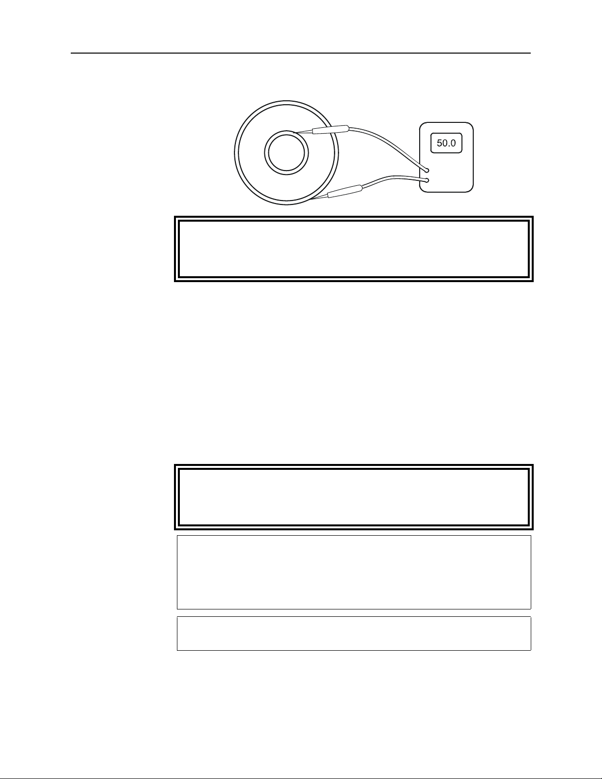
Figure 6
Measuring
Resistance
Maintenance
WARNING
Never attempt to connect or disconnect RF equipment from the
transmission line while RF power is being applied.
Leaking RF energy is a potential health hazard.
y Turn off the RF power and interlock circuitry.
y Disconnect the RF line.
Coolant
y Connect the multimeter test leads to the center and outer
conductor of the load. Refer to Figure 6.
y Compare the measured value with the previous measurement and
with the baseline resistance, measured when the load was put
into service. If the new value differs from either of these by more
than 2 ohms this could indicate a failing resistor.
WARNING
Ethylene glycol is toxic. Do not take internally. Avoid contact with
eyes, skin, and clothing. Avoid breathing vapor. Wash thoroughly
after handling.
CAUTION
Use only distilled water or the supplied ethylene glycol as coolant.
Do not use tap water, automotive antifreeze, sealants, or leak
stopping material. Use of these materials will damage the
instrument and void all warranties.
CAUTION
Operation without sufficient coolant can damage the unit.
Changing Coolant Follow these instructions to change the coolant. To just add coolant,
go to step 5. To just drain the coolant, follow steps 1 – 4.
15
Page 27
Bird 8640 Series Moduload RF Load Resistor
1. Get a clean container, with a capacity of 3 gal. (11 L), to hold the
old coolant.
2. Remove the filler cap on top of the heat exchanger. This will allow
the coolant to drain faster.
3. Unscrew and remove the drain plug on the rear of the load. Drain
the coolant into the container.
NOTE: If the coolant has no contaminants it may be reused.
4. Replace the drain plug and screw it tightly into place.
5. Remove the filler cap on top of the heat exchanger.
6. Add about 3 quarts (2.9 L) of coolant.
7. Turn the unit on for a few seconds to draw coolant into the system.
8. Repeat steps 6 and 7 twice more, until the the coolant remains
steady at or just below the high mark on the level gauge.
9. Replace the filler cap.
10. Turn the unit on and run it for five minutes to remove any air
trapped in the system.
Coolant Flush If the coolant is contaminated, for example by pipe sealant or a
broken resistor, the system should be thoroughly flushed. To do this:
1. Fill the unit with clean, potable water.
2. Run the unit for five minutes with no RF power applied.
3. Drain the coolant and discard it.
4. Repeat steps 1 – 3 until the drained liquid is clear.
5. Refill the system with proper coolant (distilled water or a distilled
water/ethylene glycol mixture) as described above.
Repair
WARNING
Disconnect the unit from all power sources before servicing.
The unit may be energized from multiple sources.
The potential for electric shock exists.
16
Fuse 1. Correct the fuse burnout cause.
2. Use a flat blade screwdriver to lift the tab securing the fuse
drawer, above the ac mains connector.
Page 28

Maintenance
3. Remove the defective fuse.
4. Replace with the same type and rating fuse
Series 115 Vac: 230 Vac
8640 15 amp 8 amp
8640B 15 amp 8 amp
5. Replace the fuse drawer.
Interlock Relay The interlock relay cannot be repaired in the field. To replace it,
follow the instructions below for your model.
WARNING
Disconnect the unit from all power sources before servicing.
The unit may be energized from multiple sources.
The potential for electric shock exists.
Model 864x
1. The relay is located on the inside of the front panel at the upper
right side.
2. Loosen the screw at the top of the relay clamp.
3. Remove the relay cartridge.
4. Line up the center pin on the new relay with the hole in the
socket, rotate until the keyway engages, then push in.
Model 864xB
1. The relay is located on the inside of the front panel at the upper
right side.
2. Loosen and remove the nut and washers that secure the relay to
the panel.
3. Record the color of each wire and the relay terminal to which it
connects then remove the wires from the relay.
4. Remove the relay from its mounting screw.
5. Install the replacement relay by reversing Step 2 through Step 4.
Flow Switch The coolant flow switch should be inspected every three to six
months, depending on the amount of use. To inspect it:
17
Page 29

Bird 8640 Series Moduload RF Load Resistor
1. Drain the coolant (see “Changing Coolant” on page 15).
2. Remove the top panel
3. Unscrew the collar holding the wired sensor plug in the flow
switch body.
4. Being careful not to lose the spring and sliding valve on the sensor
plug stem, remove the sensor plug.
5. Clean and replace the sensor plug.
6. Reassemble the unit and replace the coolant.
To replace the flow switch:
1. Disconnect the wires at the flow switch.
2. Disconnect the hoses from the flow switch, then unscrew the flow
switch from the load.
Load Removal
WARNING
Radiator fins are very sharp. Avoid contact with the radiator fins.
Failure to comply may result in severe cuts and bleeding.
WARNING
Dangerous voltages are present.
Disconnect the unit from all power line and RF power sources
before servicing. Do not disconnect the unit from the RF
transmission line while RF power is applied.
Failure to comply may result in severe electrical shock or death.
Model 864x
1. Disconnect the RF line.
2. Drain the coolant (see “Changing Coolant” on page 15).
3. Remove the screws that secure the top panel.
4. Lift the top panel and disconnect the fan-supply plug located on
top of the radiator block.
5. Loosen the hose clamps on both water hose connections to the
load.
18
6. On the inside of the front panel, remove the nuts holding the load
to the front panel.
Page 30

Maintenance
NOTE: Remove the nuts only. Do not disturb the screws. The
screws also secure the outer conductor assembly to the load. Hold
this assembly to keep it from falling and being damaged.
7. Unscrew the mounting clamp holding the load to the rest of the
unit. Remove the top half of the clamp.
8. Carefully push the load forward a few inches to access the wires
and water connection fittings.
9. Disconnect the flow switch wires from the front panel.
10. Note the position and direction of the flow switch and the output
elbow on the load. Unscrew these from the load.
11. The load can now be removed from the unit.
Model 864xB
1. Disconnect the RF line.
2. Drain the coolant (see “Changing Coolant” on page 15).
3. Remove the screws that secure the top panel.
4. Lift the top panel and disconnect the fan-supply plug located on
top of the radiator block (Figure 7).
5. Loosen the hose clamps on both water hose connections to the
load.
6. Remove the screws that secure the load mounting clamp. Remove
the top half of the mounting clamp.
7. Disconnect the flow switch wires. One at the flow switch, the
other at the in-line connector near the flow switch.
8. Disconnect the front panel wires at the connector on top of the
radiator.
19
Page 31

Bird 8640 Series Moduload RF Load Resistor
E
R
M
A
L
I
N
E
R
I
N
OUT
1
1
2
2
3
4
Figure 7
Removing the
Load
Item Description
1 Load mounting clamp screws
2 Flow switch wires
3 Fan-supply connector
4 Front panel connector
20
Page 32

Maintenance
YEL
GRN / YEL
WHT
BLK
GRN / YEL
WHT
WHT
BLK
BLK
ORG
GRN / YEL
BLK
RED
WHT
BLK
9. Record the wire colors and locations then disconnect the pump
motor wires from the front panel terminal block (TB 1) (Figure 8).
10. Remove the screws that secure the front panel to the unit then tilt
the top of the panel away from the unit and remove the two water
hoses from the load water pipes.
11. Remove the front panel with the load attached.
12. Remove the nuts and lock washers that secure the load to the
panel.
13. Remove the socket head cap screws that secure the water chamber
to the load then remove the water chamber.
14. Inspect the water chamber to be sure it is in good condition and
that the inner o-ring seal is good. If appropriate, order
replacement parts.
Figure 8
Front Panel Wiring
21
Page 33

Bird 8640 Series Moduload RF Load Resistor
Pump Removal
Disconnect the unit from all power sources before servicing.
1. Drain the coolant (see “Changing Coolant” on page 15).
2. Remove the load (see “Load Removal” on page 18).
3. Disconnect the pump wire leads from the terminal block on the
inside of the front panel.
4. Loosen the hose clamps on the input and output hoses to the
pump, and remove the hoses.
5. Loosen the hose clamp on the drain tube at the base of the pump.
Remove the drain tube.
6. Unscrew the bolts securing the base of the pump to the unit.
WARNING
The unit may be energized from multiple sources.
The potential for electric shock exists.
7. Carefully remove the pump from the unit.
8. Note the position and direction of the fittings, then twist them off
counterclockwise.
9. To replace the pump, reverse the above steps. When replacing the
threaded fittings, carefully coat the external threads, ONLY, with
a pipe sealing compound. Coating only the external threads
reduces the chances of contaminating the coolant.
22
Page 34

Resistor Servicing
1/4-20 x 2-1/2
Socket Head Cap Screw (6)
Water Chamber With
O-Ring Inner Seal
Outer O-Ring
Inner O-Ring
Resistor Sleeve
Resistor
Outer Flow Tube
Load Housing
O-Ring
Inner Flow Tube
Ground Cap Assembly
Hose Fitting 90°
Hose Fitting Straight
6
3
and
4
2
7
1
5A
5
10
9
8
17
9A
Load Housing
Resistor
Center Conductor
Assembly
1/4-20 x 1-1/2
Socket Head Cap Screw (6)
Outer Conductor
Assembly
Resistor Fitting Seal O-Ring
12
16
11
1
15
The load is designed to be quickly and easily repaired in the field. If a
significant change in the dc resistance is noted or if the resistor
should fail, inexpensive replacement resistors are available.
Maintenance
WARNING
Disconnect the unit from all power sources before servicing.
The unit may be energized from multiple sources.
The potential for electric shock exists.
Figure 9
Load Exploded View
Resistor Removal Numbers in brackets [ ] refer to the labeled parts in Figure 9.
1. Disconnect the load (see “Load Removal” on page 18).
2. Turn the load on end with the hose fitting up.
23
Page 35

Bird 8640 Series Moduload RF Load Resistor
3. Use a
approximately
3
⁄
hex socket wrench to back the cap screws [6]
16
1
⁄
2
inch.
4. Pull the water chamber assembly out. It may be necessary to rock
the chamber gently while pulling.
5. If the resistor [1] is intact it may be pulled straight out of the load
housing and is ready for replacement. The outer flow tube is
captive and will not come out of the housing at this stage.
The ground cap assembly [10] and the inner flow tube [9] should come
out with the water chamber assembly. To remove the ground cap
assembly [10], hold the resistor sleeve [7] on the flow tube and pull
out the assembly. This includes the cushioning O-Ring [8] which fits
loosely below the stop sleeve; do not lose it.
The resistor sleeve [7] has a small escape hole at the side and an
access counter bore leading to it. If the sleeve is removed, be sure this
counterbore faces the O-Ring and the resistor [1] during reassembly.
This is essential for internal water venting. The base of the inner flow
tube has water outlet holes and a small shoulder. At reassembly,
these must fit into mating recesses in the input fitting.
Inspection y Carefully check the resistor [1] for fractures.
NOTE: Even in the event of resistor failure the resistor substrate
will usually remain intact.
y Check the inside of the load housing for damage to the internal
parts. If no damage has been found proceed to “Resistor
Replacement”. However, if the resistor is broken, other internal
parts are damaged, or if the parts do not fit together properly,
proceed to “Fractured Resistor”.
Fractured Resistor 1. Turn the load on end with the RF input connector up to allow any
loose pieces of the resistor to fall out of the housing.
3
⁄
2. Use a
3. Remove the outer conductor assembly [12].
4. Pull out the center conductor assembly [11]. Carefully remove any
remaining pieces of the resistor. Normally the outer flow tube will
remain with the load housing. If it comes out, return it after
inspection and cleaning.
5. Check the inside of the load housing for damage.
hex socket wrench to remove the cap screws [16].
16
24
Page 36

Maintenance
6. Remove the inner flow tube [9] and ground cap assembly [10].
Check them for broken pieces.
7. Under clear running water, thoroughly wash the inside of the
conductor assemblies, load housing, and water chamber.
8. Replace the ground cap assembly and the inner flow tube.
Resistor
Replacement
1. Insert the new resistor [1] into the resistor fitting of the center
conductor assembly [15] to test its tightness.
2. The resistor should be snug but should not have to be forced into
the fitting. If the resistor is too loose, press the fitting fingers
together slightly and try the resistor again. Continue closing the
ends of the resistor fitting until a snug fit is obtained.
3. Bottom the resistor in the fitting.
4. Insert the resistor and the center conductor assembly into the
load housing.
5. Replace the outer conductor assembly [12] and screw it into place.
6. Stand the load on its end with the RF connector down.
7. Replace the ground cap assembly onto the exposed end of the
resistor. Make sure that it seats on the load housing.
8. If the inner flow tube [9] is separated from the water chamber
assembly [3], place it inside the resistor and lower until it reaches
the resistor fitting. Gently twist the flow tube until it seats in the
bottom of the resistor fitting.
9. Check that the O-Ring [8] is on the inner flow tube next to the
resistor and the resistor sleeve [7] is right behind it. Make sure
the counterbore faces the O-Ring and the resistor.
10. Replace the water chamber [3], gently rocking and twisting the
chamber to achieve a flat seat on the outer housing.
NOTE: If the water chamber does not fit properly make sure that
the inner flow tube is properly placed.
11. Tighten the water chamber screws [6].
12. Check the dc resistance between the inner and outer conductors;
it should be about 50 ohms. Record this measurement as the new
baseline reading.
13. Install the load on the heat exchanger. Connect the hoses and fill
with coolant.
25
Page 37

Bird 8640 Series Moduload RF Load Resistor
14. Run the pump for five minutes and check for leaks before applying
RF power.
Conductor
Replacement
1. Use a
3
⁄
allen wrench to remove the cap screws [16] from the RF
16
connector.
2. Remove the outer conductor assembly [12].
NOTE: If only the outer conductor needs replaced, install it now
and screw it into place.
3. Remove the center conductor assembly [11] by pulling it carefully
out of the load housing. Make sure the resistor [1] and inner flow
tube [9] do not come out with the center conductor.
4. Insert the new center conductor assembly into load housing. Make
sure the resistor fitting makes a snug fit with the resistor.
5. Replace the outer conductor and screw it into place.
26
Page 38

Preparation for Storage or Shipment
Store the Bird 8640 in a cool, dry area. For pure water-cooled units,
the ambient temperature must be within 5°C to 50°C (41°F to 122°F).
For units with 35% ethylene glycol, the ambient temperature must be
within –25°C to 45°C (–13°F to 113°F). Drain the coolant (see
“Changing Coolant” on page 15) if the unit will be stored for more
than 30 days.
To ship, pack the unit in its original shipping container. If this is not
available, securely pack and seal it in a sturdy wooden box or
equivalent, with sufficient padding to avoid shock damage.
Customer Service
Any maintenance or service procedure beyond the scope of those in
this chapter should be referred to a qualified service center.
Maintenance
If you need to return the unit for any reason, contact the Bird Service
Center for a return authorization. All instruments returned must be
shipped prepaid and to the attention of Bird Service Center.
Bird Service Center
30303 Aurora Road
Cleveland (Solon), OH 44139-2794
Phone: (440) 519-2298
Fax: (440) 519-2326
E-mail: bsc@bird-technologies.com
For the location of the Sales Office nearest you, give us a call or visit
our Web site at:
http://www.bird-electronic.com
27
Page 39

Bird 8640 Series Moduload RF Load Resistor
Specifications
Frequency Range
Power Rating
Mode
Impedance
VSWR
Connectors
8645
8646
Interlock Rating
Cooling Method
Coolant
*
Coolant Capacity
AC Power
–115
–230
–230–6
1 kHz – 900 MHz
25 kW continuous duty
CW, AM, FM, SSB, TV and certain pulse types
50 ohms nominal
1.10 max
1
3
⁄
inch EIA Flanged
8
1
3
⁄
inch Unflanged
8
NO or NC Connections
5A @ 250 Vac
10A @ 125 Vac
48 Vdc
Water dielectric and forced air convection
Distilled water or distilled water/ethylene glycol
mixture
9 qts. (8.5 L) nominal
115 Vac @ 11 A, 60 Hz
230 Vac @ 5.5 A, 50 Hz
230 Vac @ 5.5 A, 60 Hz
Fuse Rating (864x)
115 Vac
230 Vac
Fuse Rating (864xB)
115 Vac
230 Vac
Ambient Temperature
Water only
35% Ethylene Glycol
Dimensions
Weight, Nominal
* Below 5°C, ONLY use 35% E.G. and 65% Dist. H2O mixture
† Above 30°C (86 °F) with water only, or 25°C (77 °F) with a 35% ethylene
glycol mixture, derate power to 20 kW max.
3AB Time-Delay
15 A
8 A
Time-Delay
15 A (3AB)
8 A (5x20 mm)
†
+5 to +45† °C (41 to 113 °F)
–20 to +35
26"L x 19-5/8"W x 19-1/4"H (670 x 500 x 490 mm)
154 lb. (70 kg)
†
°C (–4 to +95 °F)
28
Page 40

Replacement Parts
1/4-20 x 2-1/2
Socket Head Cap Screw (6)
Water Chamber With
O-Ring Inner Seal
Outer O-Ring
Inner O-Ring
Resistor Sleeve
Resistor
Outer Flow Tube
Load Housing
O-Ring
Inner Flow Tube
Ground Cap Assembly
Hose Fitting 90°
Hose Fitting Straight
6
3
and
4
2
7
1
5A
5
10
9
8
17
9A
Load Housing
Resistor
Center Conductor
Assembly
1/4-20 x 1-1/2
Socket Head Cap Screw (6)
Outer Conductor
Assembly
Resistor Fitting Seal O-Ring
12
16
11
1
15
The parts lists in this section identify the components of the Bird
Moduload. Exploded views are used to illustrate the component parts
and indicate their relation to each other. Each part in the exploded
view has an item number referencing the part list.
Maintenance
Figure 10
Load Exploded View
29
Page 41

Bird 8640 Series Moduload RF Load Resistor
Load
ITEM
DESCRIPTION QTY PART NO.
NO.
Load Complete
8645
8646
1 Resistor 1 8755-027
2 Outer O-Ring 1 8410-009
3 Water Chamber 1 8755-014
4 Water Chamber Inner O-Ring 1 5-099
5 Fitting, 90° 1 8640-089
5A Fitting, Straight, consisting of:
Bushing
Nipple
6 Screw
1
⁄
-20 x 2-
4
1
⁄
inch 6 1121-2508-00
2
7 Resistor Sleeve 1 8755-026
8 Sleeve O-Ring 1 8110-059
9 Inner Flow Tube 1 8755-025
1
8745-101-1
8746-101
1
1
5-489-1
5-490-1
9A Outer Flow Tube 1 8755-024
10 Resistor Ground Cap 1 8755-005
11 Center Conductor Assembly
8645
8646
12 Outer Conductor Assembly
8645
8646
1
8755-007
8756-003
1
8755-004
8756-002
15 Center Conductor O-Ring 1 5-1127
16 Screw
1
⁄
-20 x 1-
4
1
⁄
inch 6 1121-1808-00
2
17 Inner O-Ring 1 5-567
30
Page 42

Maintenance
Heat Exchanger
DESCRIPTION QTY PART NO.
AC Cord
864x-115
864x-230
Fan Assembly (model 864x)
864x-115
864x-230 and 864x-230-6
8646-230-6-N
Fan Assembly (model 864xB)
864xB - 115
864xB - 230 and 864xB -
230-6
Pump (model 864x)
864x-115
864x-230
864x-230-6
Pump (model 864xB)
864xB - 115
864xB - 230
864xB - 230-6
1
5-1836
5-1837
2
8640-668-1
8640-668-2
8640-668-4
2
5A2770-1
5A2770-2
1
8640A505-1
8640A505-2
8640A505-4
1
8640B505-1
8640B505-2
8640B505-4
Flow Switch Assy (model 864x) 1 8645-004
Flow Switch Assy (model 864xB) 1 8645B004
Interlock Relay
864x-115
864x-230
864xB series
Fuse (model 864x)
864x and 864xB -115
864x - 230
864xB - 230
Fuse (model 864xB)
864xB - 115
864xB - 230
1
5-1627
5-1625
5A2787-1
2
5-1828-36 (15 A 3AB time delay)
5-1828-33 (8 amp 3AB time delay)
5A2257-25 (8 amp 5x20 mm)
2
5-1828-36 (15 A 3AB time delay)
5A2257-25 (8 A 5x20 mm)
Coolant Gauge Kit 1 5-1200
Ethylene Glycol 1
5-1134-3
Gal.
31
Page 43

Bird 8640 Series Moduload RF Load Resistor
32
Page 44

Limited Warranty
All products manufactured by Seller are warranted to be free from defects in
material and workmanship for a period of one (1) year, unless otherwise
specified, from date of shipment and to conform to applicable specifications,
drawings, blueprints and/or samples. Seller’s sole obligation under these
warranties shall be to issue credit, repair or replace any item or part thereof
which is proved to be other than as warranted; no allowance shall be made for
any labor charges of Buyer for replacement of parts, adjustment or repairs, or
any other work, unless such charges are authorized in advance by Seller.
If Seller’s products are claimed to be defective in material or workmanship or not
to conform to specifications, drawings, blueprints and/or samples, Seller shall,
upon prompt notice thereof, either examine the products where they are located
or issue shipping instructions for return to Seller (transportation-charges
prepaid by Buyer). In the event any of our products are proved to be other than
as warranted, transportation costs (cheapest way) to and from Seller’s plant, will
be borne by Seller and reimbursement or credit will be made for amounts so
expended by Buyer. Every such claim for breach of these warranties shall be
deemed to be waived by Buyer unless made in writing within ten (10) days from
the date of discovery of the defect.
The above warranties shall not extend to any products or parts thereof which
have been subjected to any misuse or neglect, damaged by accident, rendered
defective by reason of improper installation or by the performance of repairs or
alterations outside of our plant, and shall not apply to any goods or parts thereof
furnished by Buyer or acquired from others at Buyer’s request and/or to Buyer’s
specifications. Routine (regularly required) calibration is not covered under this
limited warranty. In addition, Seller’s warranties do not extend to the failure of
tubes, transistors, fuses and batteries, or to other equipment and parts
manufactured by others except to the extent of the original manufacturer’s
warranty to Seller.
The obligations under the foregoing warranties are limited to the precise terms
thereof. These warranties provide exclusive remedies, expressly in lieu of all
other remedies including claims for special or consequential damages. SELLER
NEITHER MAKES NOR ASSUMES ANY OTHER WARRANTY WHATSOEVER, WHETHER EXPRESS, STATUTORY, OR IMPLIED, INCLUDING
WARRANTIES OF MERCHANTABILITY AND FITNESS, AND NO PERSON
IS AUTHORIZED TO ASSUME FOR SELLER ANY OBLIGATION OR
LIABILITY NOT STRICTLY IN ACCORDANCE WITH THE FOREGOING.
 Loading...