

Page 1

INSTRUCTION BOOK
AIR COOLED RF LOAD RESISTOR
MODEL 8578A, 8578B
©Copyright 2012 by Bird Electronic Corporation
Instruction Book Part Number 920-8578AS Rev. D
Moduload
®
, Econoload®, Econoline®, and Thruline® are
registered trademarks of Bird Electronic Corporation
Page 2

I am not blank
Page 3
Safety Precautions
The following are general safety precautions that are not necessarily related to any
specific part or procedure, and do not necessarily appear elsewhere in this publication. These precautions must be thoroughly understood and apply to all phases of
operation and maintenance.
WARNING
Keep Away From Live Circuits
Operating Personnel must at all times observe general safety precautions. Do not
replace components or make adjustments to the inside of the test equipment with
the high voltage supply turned on. To avoid casualties, always remove power.
WARNING
Shock Hazard
Do not attempt to remove the RF transmission line while RF power is present.
WARNING
Do Not Service Or Adjust Alone
Under no circumstances should any person reach into an enclosure for the
purpose of service or adjustment of equipment except in the presence of
someone who is capable of rendering aid.
WARNING
Safety Earth Ground
An uniterruptible earth safety ground must be supplied from the main power
source to test instruments. Grounding one conductor of a two conductor power
cable is not sufficient protection. Serious injury or death can occur if this
grounding is not properly supplied.
WARNING
Resuscitation
Personnel working with or near high voltages should be familiar with modern
methods of resuscitation.
WARNING
Remove Power
Observe general safety precautions. Do not open the instrument with the power on.
Safety Symbols
WARNING
Warning notes call attention to a procedure, which if not correctly performed,
could result in personal injury.
CAUTION
Caution notes call attention to a procedure, which if not correctly performed,
could result in damage to the instrument.
Note: Calls attention to supplemental information.
i
Page 4
Bird 8578 Series RF Load Resistor
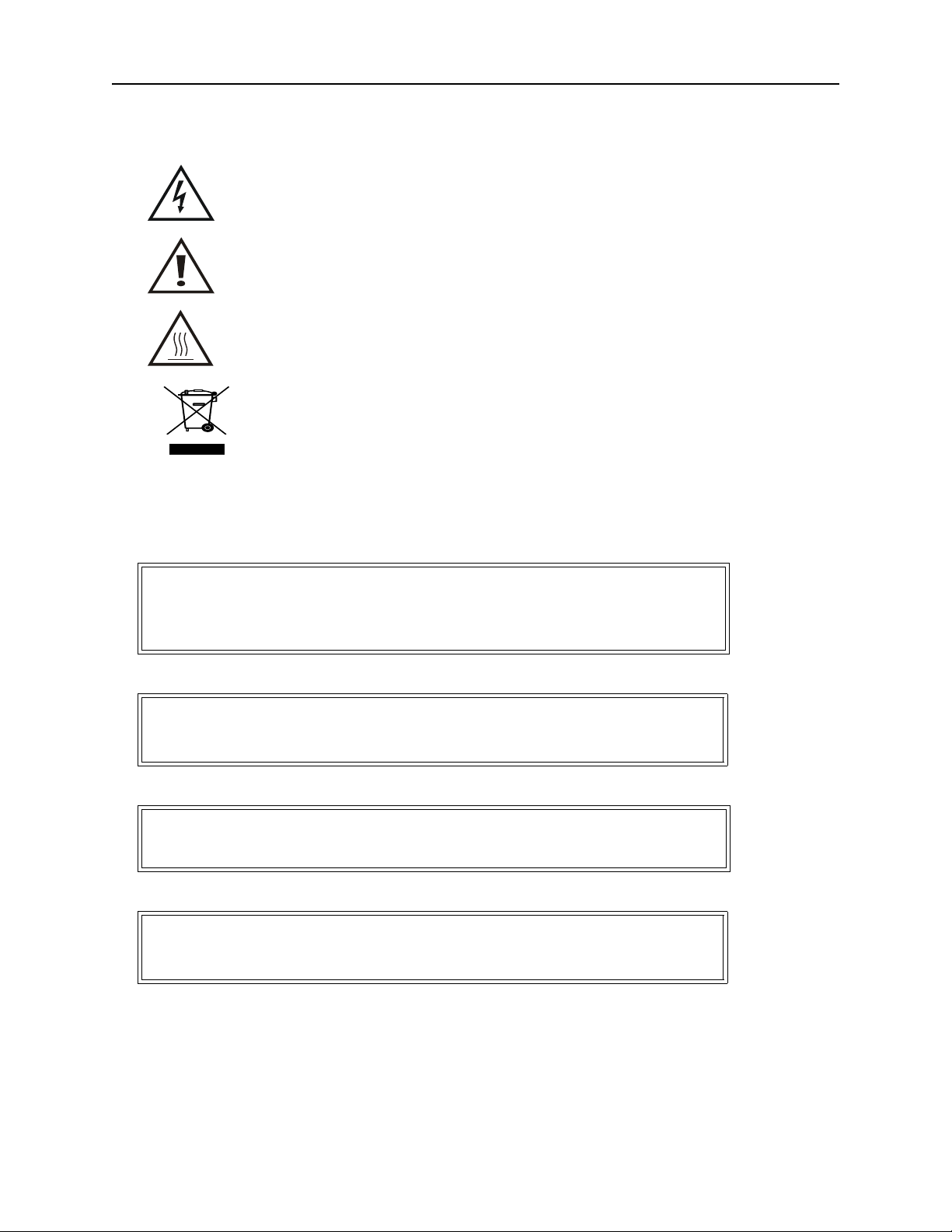
This symbol indicates that a shock hazard exists if the precautions in the instruction manual are not followed.
The caution symbol appears on the equipment indicating there
is important information in the instruction manual regarding
that particular area.
This symbol indicates that the unit radiates heat and should not
be touched while hot.
This symbol appears on the equipment and indicates the
requirement for separate collection of discarded electrical and
electronic equipment in accordance with the European Union
Directive 2002/96/EC.
Warning Statements
The following safety warnings appear in the text where there is danger to operating and maintenance personnel, and are repeated here for emphasis.
WARNING
Do not insert any thin metal objects through the perforated cooling air grilles
while the load is in operation. Otherwise, the power within the unit could arc
over and cause serious bodily injury and/or damage to the unit.
Refer to page 1.
WARNING
Although the interlock terminal is rated to 230 VAC, limit the interlock terminal to
less than 30 Vrms. Otherwise, the potential for electrical shock exists.
Refer to pages 7 and 11.
WARNING
Do not touch the surface of the load. The surface may become hot when power is
applied to load.
Refer to page 12.
WARNING
Disconnect from RF power sources and the AC line before any disassembly or
service. Otherwise, there is a potential for electrical shock.
Refer to pages 13, 14 and 15.
ii
Page 5

Caution Statements
The following equipment cautions appear in the text and are repeated here for
emphasis.
CAUTION
Do not block air flow. Air enters through perforated grilles at the top of the unit
and exhausts through a lower grill in the unit. Blocking these grilles could
cause unit failure.
Refer to page 7.
CAUTION
Ensure the 115/230 voltage selector on the front panel of the unit is set to the
proper voltage before AC power is applied. Incorrect voltage setting can
permentaly damage the unit
Refer to page 7.
CAUTION
Do not block or restrict the air flow over the resistor array. Otherwise, the load
will overheat and become damaged beyond repair.
Refer to page 11.
CAUTION
Do not apply more than the rated RF power to load. Excessive RF power will
damage the load resistors.
Refer to page 11.
CAUTION
Do not use excessive force, as there is the possibility of the resistors chipping or
cracking
Refer to page 15.
iii
Page 6

Bird 8578 Series RF Load Resistor
Safety Statements
USAGE
ANY USE OF THIS INSTRUMENT IN A MANNER NOT SPECIFIED BY THE
MANUFACTURER MAY IMPAIR THE INSTRUMENT’S SAFETY
PROTECTION.
USO
EL USO DE ESTE INSTRUMENTO DE MANERA NO ESPECIFICADA POR EL
FABRICANTE, PUEDE ANULAR LA PROTECCIÓN DE SEGURIDAD DEL
INSTRUMENTO.
BENUTZUNG
WIRD DAS GERÄT AUF ANDERE WEISE VERWENDET ALS VOM
HERSTELLER BESCHRIEBEN, KANN DIE GERÄTESICHERHEIT
BEEINTRÄCHTIGT WERDEN.
UTILISATION
TOUTE UTILISATION DE CET INSTRUMENT QUI N’EST PAS
EXPLICITEMENT PRÉVUE PAR LE FABRICANT PEUT ENDOMMAGER LE
DISPOSITIF DE PROTECTION DE L’INSTRUMENT.
IMPIEGO
QUALORA QUESTO STRUMENTO VENISSE UTILIZZATO IN MODO
DIVERSO DA COME SPECIFICATO DAL PRODUTTORE LA PROZIONE DI
SICUREZZA POTREBBE VENIRNE COMPROMESSA.
iv
Page 7

SERVICE
SERVICING INSTRUCTIONS ARE FOR USE BY SERVICE - TRAINED
PERSONNEL ONLY. TO AVOID DANGEROUS ELECTRIC SHOCK, DO NOT
PERFORM ANY SERVICING UNLESS QUALIFIED TO DO SO.
SERVICIO
LAS INSTRUCCIONES DE SERVICIO SON PARA USO EXCLUSIVO DEL
PERSONAL DE SERVICIO CAPACITADO. PARA EVITAR EL PELIGRO DE
DESCARGAS ELÉCTRICAS, NO REALICE NINGÚN SERVICIO A MENOS
QUE ESTÉ CAPACITADO PARA HACERIO.
WARTUNG
ANWEISUNGEN FÜR DIE WARTUNG DES GERÄTES GELTEN NUR FÜR
GESCHULTES FACHPERSONAL.
ZUR VERMEIDUNG GEFÄHRLICHE, ELEKTRISCHE SCHOCKS, SIND
WARTUNGSARBEITEN AUSSCHLIEßLICH VON QUALIFIZIERTEM
SERVICEPERSONAL DURCHZUFÜHREN.
ENTRENTIEN
L’EMPLOI DES INSTRUCTIONS D’ENTRETIEN DOIT ÊTRE RÉSERVÉ AU
PERSONNEL FORMÉ AUX OPÉRATIONS D’ENTRETIEN. POUR PRÉVENIR
UN CHOC ÉLECTRIQUE DANGEREUX, NE PAS EFFECTUER D’ENTRETIEN
SI L’ON N’A PAS ÉTÉ QUALIFIÉ POUR CE FAIRE.
ASSISTENZA TECNICA
LE ISTRUZIONI RELATIVE ALL’ASSISTENZA SONO PREVISTE
ESCLUSIVAMENTE PER IL PERSONALE OPPORTUNAMENTE
ADDESTRATO. PER EVITARE PERICOLOSE SCOSSE ELETTRICHE NON
EFFETTUARRE ALCUNA RIPARAZIONE A MENO CHE QUALIFICATI A
FARLA.
v
Page 8

Bird 8578 Series RF Load Resistor
CONNECT INTERLOCK TO TRANSMITTER BEFORE OPERATING.
BRANCHER LE VERROUILLAGE À L'ÉMETTEUR AVANT EMPLOI.
CONECTE EL INTERBLOQUEO AL TRANSMISOR ANTES DE LA OPERACION.
VOR INBETRIEBNAHME VERRIEGELUNG AM SENDER ANSCHLIESSEN.
PRIMA DI METTERE IN FUNZIONE L'APPARECCHIO, COLLEGARE IL
DISPOSITIVO DI BLOCCO AL TRASMETTITORE
vi
Page 9

About This Manual
This instruction book covers the following Termaline Load Resistor models:
8578A100 8578A150
8578B150 8578B100
Changes to this Manual
We have made every effort to ensure this manual is accurate. If you discover any
errors, or if you have suggestions for improving this manual, please send your
comments to our Solon, Ohio factory. This manual may be periodically updated.
When inquiring about updates to this manual refer to the part number and revision on the title page.
Literature Contents
Chapter Layout
Introduction - Describes the features of the Bird 8578A and B Loads, lists equip-
ment supplied and optional equipment, and provides power-up instructions.
Theory of Operation - Describes how the Bird 8578A and B Loads work.
Installation - Describes procedures required for setting up Bird 8578A and B
Loads.
Operating Instructions - Describes procedures required for operating the Bird
8578A and B Loads.
Maintenance - Lists routine maintenance tasks as well as troubleshooting for
common problems. Specifications and parts information are also included.
vii
Page 10

Bird 8578 Series RF Load Resistor
viii
Page 11

Table of Contents
Safety Precautions. . . . . . . . . . . . . . . . . . . . . . . . . . . . . . . . . . . . . . . . . . . . . . i
Safety Symbols . . . . . . . . . . . . . . . . . . . . . . . . . . . . . . . . . . . . . . . . . . . . . i
Warning Statements . . . . . . . . . . . . . . . . . . . . . . . . . . . . . . . . . . . . . . . . . . ii
Caution Statements . . . . . . . . . . . . . . . . . . . . . . . . . . . . . . . . . . . . . . . . . iii
Safety Statements . . . . . . . . . . . . . . . . . . . . . . . . . . . . . . . . . . . . . . . . . . . iv
About This Manual. . . . . . . . . . . . . . . . . . . . . . . . . . . . . . . . . . . . . . . . . . . vii
Changes to this Manual . . . . . . . . . . . . . . . . . . . . . . . . . . . . . . . . . . . . . . vii
Literature Contents . . . . . . . . . . . . . . . . . . . . . . . . . . . . . . . . . . . . . . . . . vii
Chapter Layout . . . . . . . . . . . . . . . . . . . . . . . . . . . . . . . . . . . . . . . . . . . vii
Chapter 1 Introduction . . . . . . . . . . . . . . . . . . . . . . . . . . . . . . . . . . . . . . . . . 1
General . . . . . . . . . . . . . . . . . . . . . . . . . . . . . . . . . . . . . . . . . . . . . . . . . . . . 1
Description . . . . . . . . . . . . . . . . . . . . . . . . . . . . . . . . . . . . . . . . . . . . . . . . . 1
Items Supplied . . . . . . . . . . . . . . . . . . . . . . . . . . . . . . . . . . . . . . . . . . . . . . 1
Specifications . . . . . . . . . . . . . . . . . . . . . . . . . . . . . . . . . . . . . . . . . . . . . . . 2
Unpacking and Inspection . . . . . . . . . . . . . . . . . . . . . . . . . . . . . . . . . . . . . 3
Site and Shelter Requirements . . . . . . . . . . . . . . . . . . . . . . . . . . . . . . . . . . 3
Chapter 2 Theory of Operation. . . . . . . . . . . . . . . . . . . . . . . . . . . . . . . . . . 5
General . . . . . . . . . . . . . . . . . . . . . . . . . . . . . . . . . . . . . . . . . . . . . . . . . . . . 5
RF Section Description . . . . . . . . . . . . . . . . . . . . . . . . . . . . . . . . . . . . . . . 5
Heat Transfer . . . . . . . . . . . . . . . . . . . . . . . . . . . . . . . . . . . . . . . . . . . . . . . 5
Interlock Control Circuit . . . . . . . . . . . . . . . . . . . . . . . . . . . . . . . . . . . . . . 5
Chapter 3 Installation. . . . . . . . . . . . . . . . . . . . . . . . . . . . . . . . . . . . . . . . . . 7
Location Mounting . . . . . . . . . . . . . . . . . . . . . . . . . . . . . . . . . . . . . . . . . . 7
Placement . . . . . . . . . . . . . . . . . . . . . . . . . . . . . . . . . . . . . . . . . . . . . . . . . . 7
Interlock Connections . . . . . . . . . . . . . . . . . . . . . . . . . . . . . . . . . . . . . . . . 7
Attaching the AC Line . . . . . . . . . . . . . . . . . . . . . . . . . . . . . . . . . . . . . . . . 8
Attaching the RF Line . . . . . . . . . . . . . . . . . . . . . . . . . . . . . . . . . . . . . . . . 8
Removing the 1-5/8" EIA Swivel Flange Connector . . . . . . . . . . . . . . . . . 8
Attaching the 3-1/8" Unflanged Conductor . . . . . . . . . . . . . . . . . . . . . . . . 9
Chapter 4 Operating Instructions. . . . . . . . . . . . . . . . . . . . . . . . . . . . . . . 11
General . . . . . . . . . . . . . . . . . . . . . . . . . . . . . . . . . . . . . . . . . . . . . . . . . . . 11
Load Power . . . . . . . . . . . . . . . . . . . . . . . . . . . . . . . . . . . . . . . . . . . . . . . 11
Operation Under Normal and Abnormal Conditions . . . . . . . . . . . . . . . . 11
Shutting Down . . . . . . . . . . . . . . . . . . . . . . . . . . . . . . . . . . . . . . . . . . . . . 12
Measuring and Monitoring RF Power . . . . . . . . . . . . . . . . . . . . . . . . . . . 12
Chapter 5 Maintenance . . . . . . . . . . . . . . . . . . . . . . . . . . . . . . . . . . . . . . . 13
Troubleshooting . . . . . . . . . . . . . . . . . . . . . . . . . . . . . . . . . . . . . . . . . . . . 13
Cleaning . . . . . . . . . . . . . . . . . . . . . . . . . . . . . . . . . . . . . . . . . . . . . . . . . . 13
Cleaning Outside Surfaces . . . . . . . . . . . . . . . . . . . . . . . . . . . . . . . . . . 13
Cleaning the Instrument Housing and Panels . . . . . . . . . . . . . . . . . . . 14
Cleaning the Connector and Outside Surface . . . . . . . . . . . . . . . . . . . 14
ix
Page 12

Disassembling the Enclosure . . . . . . . . . . . . . . . . . . . . . . . . . . . . . . . . . . 14
Diagnosing the RF Assembly . . . . . . . . . . . . . . . . . . . . . . . . . . . . . . . . 15
Replacing the Resistors . . . . . . . . . . . . . . . . . . . . . . . . . . . . . . . . . . . . 15
Replacing the Blower Assembly . . . . . . . . . . . . . . . . . . . . . . . . . . . . . . . 15
Motor Blower Assembly Replacement,
8578A Series . . . . . . . . . . . . . . . . . . . . . . . . . . . . . . . . . . . . . . . . . . . . 15
Motor Blower Assembly Replacement,
8578B, 100, and 150 Series . . . . . . . . . . . . . . . . . . . . . . . . . . . . . . . . . 16
Relpacing the Fuse . . . . . . . . . . . . . . . . . . . . . . . . . . . . . . . . . . . . . . . . . . 17
Replacing the AC Line Module . . . . . . . . . . . . . . . . . . . . . . . . . . . . . . . . 17
Storing . . . . . . . . . . . . . . . . . . . . . . . . . . . . . . . . . . . . . . . . . . . . . . . . . . . 17
Replacement Parts List . . . . . . . . . . . . . . . . . . . . . . . . . . . . . . . . . . . . . . 18
Models 8578A100 and 8578B100 . . . . . . . . . . . . . . . . . . . . . . . . . . . . 18
Models 8578A150 and 8578B150 . . . . . . . . . . . . . . . . . . . . . . . . . . . . 18
Customer Service . . . . . . . . . . . . . . . . . . . . . . . . . . . . . . . . . . . . . . . . . . . 19
Limited Warranty . . . . . . . . . . . . . . . . . . . . . . . . . . . . . . . . . . . . . . . . . . . . 21
x
Page 13

Chapter 1 Introduction
General
The Models 8578A100 and 8578A150 are air cooled, high powered Termaline
Load resistors designed to be quiet, rugged and trouble free. They are rigid RF
line terminations used as dummy antennas. They are forced air cooled and are
capable of dissipating RF line power up to 10 or 15 kW, depending on the
model. Virtually maintenance free and simple to operate, these units should
provide years of trouble free operation yet are field repairable in the event of
failure of the load resistor or other components. The RF sections are composed
of a parallel combination of resistors.
Description
The units are rectangular in shape. They are supported on the bottom by four
bumper feet. The RF input connector is located on the top center of the unit.
Perforated side panel grilles at the top and bottom of the units allow for direct
forced air cooling of the resistors. The AC power receptacle, ON/OFF switch
and transmitter interlock are located on the front panel of the unit. The rear
and side panels are removable for servicing. Refer to Figure 1.
Items Supplied
WARNING
Do not insert any thin metal objects through the perforated cooling air
grilles while the load is in operation. Otherwise, the power within the unit
could arc over and cause serious bodily injury and/or damage to the unit.
The following items are supplied with the 8578A and 8578B:
• Manuals CD
• Single pole fusedrawer, for 115V operation (installed)
• Fuse, 6.3A, T, for 115V operation (installed)
• Two pole fuse drawer, for 230V opertation
• 2 Fuses, 3.15A, T, for 230V operation
1
Page 14

Bird 8578 Series RF Load Resistor
Specifications
Impedance 50 ohms nominal
VSWR
Connectors Standard 1-5/8" Diameter Swivel Flange
Power Rating
Frequency Range
Dimensions
Model 8578A100, 8578B100
Model 8578A150, 8578B150
Model 8578A100, 8578B100
Model 8578A150, 8578B150
Model 8575A100
Model 8578A150
without connector
1.15:1 maximum DC-108 MHz
1.15:1 maximum 87.5-108 MHz
Optional 3-1/8" Diameter Unflanged
10 kW continuous duty
15 kW continuous duty
DC-108 MHz
87.5-108M Hz
13-7/16" L x 16-15/32" W x 36-5/8" H (341 x 418
x 730mm)
with connector
Ambient Temperature
Interlock contact rating
Cooling Method
Weight, Nominal
AC Power Requirements
Fuses
1 15 Volt operation
230 Volt operation
Finish Grey Powder Coat
13-7/16" x 16-15/32" x 39-3/32"
(341x418x993mm)
-40°C to +40°C(-40°F to 104°F)
10 Amp @ 120 VDC
5 Amp @ 240 VAC
Forced air cooled
‘A’ series: 72 lb (32.7 kg)
‘B’ series: 60 lb (27.2 kg)
115 VAC, 5 Amps Nominal
230 VAC, 2.5 Amps Nominal 50/60Hz
5 x 20mm Time-delay 6.3 Amp
5 x 20mm Time-delay 3.15 Amp
2
Page 15

Unpacking and Inspection
1. Carefully inspect the shipping container for signs of damage.
2. Do one of the following:
• If damage is noticed, do not unpack the unit. Immediately notify the
shipping carrier and Bird Electronic Corporation of the damage.
• If the container is not damaged, unpack the unit. Save the packing
materials for repacking.
3. Inspect all of the components for visual signs of damage.
Note: Immediately notify the shipping carrier and Bird Electronic
of equipment damage or missing parts.
Site and Shelter Requirements
The equipment is not intended for outdoor use, or use in areas of condensing
humidity. The surrounding air must be free of contaminants or particles that
could be drawn into the air intakes. These load resistors have no intermediate
dielectric fluids or coolant and require no cooling water hookups. The unit
should be placed where adequate space is available for air circulation and an
AC power source is available.
Introduction
Do not enclose the unit in a small room or closet without proper ventilation. In
small rooms or restricted areas, the heat given off by the unit may increase
the ambient temperature to an unacceptable level for sufficient cooling of the
resistors.
3
Page 16

Bird 8578 Series RF Load Resistor
Figure 1 Outline Drawing - (all models)
4
Page 17

Chapter 2 Theory of Operation
General
The 8578A and 8578B series consists of high powered, air cooled, RF loads
used for termination of coaxial transmission lines. The RF energy, when converted into heat, is transmitted directly to the surrounding area by the forced
air system.
RF Section Description
The RF section, of the 8578A and 8578B series, is composed of a parallel combination of tubular resistors. These resistors are carefully positioned to provide a reduction in surge impedance proportional to the distance along the
resistive system, which finally terminates to the housing forming the return
path for the coaxial circuit. This produces a very uniform and almost reflectionless line termination over the stated frequencies of the load resistor.
Heat Transfer
The resistors used in the 8578 series are of a tubular type, situated in a vertical
position within their housing. When the unit is in operation, a fan located at
the bottom of the unit draws air into the top grille openings and directs it over
the RF resistor network. The heat, developed in the resistors from dissipation
of the RF energy, is carried off by the flow of air over the resistors surface. The
hot air is then exhausted through the lower grille opening in the unit.
Interlock Control Circuit
The interlock control circuit provides fail-safe protection of the transmitter
and load resistor in the event of restricted air flow or excassive ambient temperture to the load. This protection is necessary because dissipation of the
heat generated by the RF power is critically dependent upon a required minimum flow of cooling air at all times. If the air flow over the resistor array
should stop or be restricted and the temperature in the RF chamber should
rise beyond a safe limit, the heat sensor unit will sense the change and actuate the interlock relay to reverse the process and turn off the transmitter. The
interlock system will not permit re-operation of the transmitter until the air
flow is restored and a safe low temperature in the RF housing is once again
attained.
5
Page 18

Bird 8578 Series RF Load Resistor
6
Page 19

Chapter 3 Installation
Location Mounting
There are no provisions for mounting of these units. These units are designed for
use in a vertical position, however, if the situation should arise, they may be
used in any position. If the unit is to be used in any other position, be sure the
mounting is substantial and clearance around the load is maintained for cooling.
CAUTION
Do not block air flow. Air enters through perforated grilles at the top of the
unit and exhausts through a lower grill in the unit. Blocking these grilles
could cause unit failure.
Placement
For ease of movement, hold the two handles on each side of the RF input connector, located at the top center of the unit. Move the unit into position, and
rest it on the four bumper feet.
WARNING
Although the interlock terminal is rated to 230 VAC, limit the interlock terminal
to less than 30 Vrms. Otherwise, the potential for electrical shock exists.
Interlock Connections
There are two terminals on the interlock connection of the load, with a rating of
10A @ 120V AC and 5A @ 250VAC. Check the requirements of the transmitter
interlock and make the connections to the appropriate terminals as required.
• Attach the transmitter interlock connections to the two binding posts
Figure 2 Interlock Terminal
Ensure the 115/230 voltage selector on the front panel of the unit is set to
the proper voltage before AC power is applied. Incorrect voltage setting can
on the control panel. See Figure 2.
CAUTION
permentaly damage the unit.
7
Page 20

Bird 8578 Series RF Load Resistor
Alignment Hex
screws
Button Head
screw
Attaching the AC Line
A standard AC power cord is required.
The AC power supply may be either 115 or 230 volts depending on the unit
requirements. AC is supplied to the power entry module by means of a cable
and matching plug. For proper protection, if a 3-wire type plug and outlet is not
used, fasten the green wire at the supply end to a satisfactory ground. Do not
apply RF power to the unit unless the power cord is connected and the ON/OFF
switch is in the ON position.
Note: 8578AS loads are shipped from the factory foramtted for 115
VAC operation. For 230 VAC operation, the fuses and fuse drawer must
be changed to use the two pole fuse drawer included with the unit and
the two 3.15 Amp fuses also supplied. The power entry module must
also be set to 230 volts.
Note: Ensure the proper fuses are used. The unit is shipped with
fuses installed for 115V usage. If the unit is to be used at 230V, install
the 3.15A fuses. See “Relpacing the Fuse” on page 17.
Attaching the RF Line
After installation of the load, the coaxial RF transmission line may be
attached using the standard 1-5/8" EIA Swivel Flange Connector or the
optional 3-1/8" Unflanged Connector kit p/n 8731A700.
Removing the 1-5/8" EIA Swivel Flange Connector
Note: Retain all screws for later reassembly.
1. Remove the four hex screws securing the Swivel Flange Connector to the
top of the unit.
2. Remove the Button head screw located in the center of the Inner Conductor.
Figure 3 Replacing the Flanged Connector
8
Page 21

Attaching the 3-1/8" Unflanged Conductor
1. Attach the new Inner Conductor using the button head screw.
2. Attach the 3-1/8" Unflanged Connector with 4 socket head cap screws to
the unit by aligning the alignment holes over the 4 socket head cap screws
in the top of the unit.
Note: The coupling must be fastened with all 4 of the screws.
Tighten evenly all around.
Installation
9
Page 22

Bird 8578 Series RF Load Resistor
10
Page 23

Chapter 4 Operating Instructions
General
The Models 8578A100, 8578B100, 8578A150, and 8578B150 have only one operating control, the ON/OFF switch. When installed the only requirement is for the
ON/OFF switch to be placed in the ON position. The unit is now ready to accept
RF power. Once the unit is set, there is no need for the presence of an operator.
Load Power
CAUTION
Do not block or restrict the air flow over the resistor array. Otherwise, the
load will overheat and become damaged beyond repair.
CAUTION
Do not apply more than the rated RF power to load. Excessive RF power
will damage the load resistors.
Do not operate above the rated capacity; i.e. 10kW or 15kW of power. The unit
will handle a small percentage of overload until the interlock system sensor
relay opens due to over temperature and turns off the transmitter. If a large
amount of overloading occurs, resistor failure is eminent before the interlock
system reacts.
Shortly after load power has been applied, the RF line may be too hot to touch.
Disconnect only while following the Shut Down procedure.
WARNING
Although the interlock terminal is rated to 230 VAC, limit the interlock terminal
to less than 30 Vrms. Otherwise, the potential for electrical shock exists.
Operation Under Normal and Abnormal Conditions
The interlock is for proper operation at the rated ambient condition of 40°C
(104°F).
Models 8578A100 and 8578B100 - The normally closed relay opens at 86°C ±
3°C (186.8°F ± 5.4°F) and closes at 80°C ± 3°C (176°F ± 5.4°F).
Models 8578A150 and 8578B150 - The normally closed relay opens at 125°C ±
3.5°C (257°F ± 6.3°F), and closes at 100°C ± 5°C (212°F ± 9°F).
11
Page 24

Bird 8578 Series RF Load Resistor
Shutting Down
1. Turn the transmitter off.
Do not touch the surface of the load. The surface may become hot when
2. Disconnect the RF line.
3. Allow the fan motor to continue running for a few minutes to allow the
resistive elements and the surface to cool.
4. Remove AC power.
Measuring and Monitoring RF Power
The Models 8578A100, 8578B100, 8578A150, and 8578B150 Load Resistors
may be used in conjunction with any one of the various Bird rigid coaxial line
Thruline
wattmeter, either model becomes a useful tool for tuning and adjusting a
transmitter as well as monitoring RF power directly in watts. Call a Bird
Sales office for more information about Thruline wattmeters. See “Customer
Service” on page 19.
®
Wattmeters. When fitted with the appropriate line section and
WARNING
power is applied to load.
12
Page 25

Chapter 5 Maintenance
Troubleshooting
WARNING
Disconnect from RF power sources and the AC line before any disassembly
or service. Otherwise, there is a potential for electrical shock.
Note: For corrections requiring repair or replacement of compo-
nents, refer to the appropriate section for your specific model. Only
those functions within the scope of normal maintenance are listed. This
manual cannot list all malfunctions that may occur, or corrective
actions. If a malfunction is not listed or is not corrected by listed corrective actions, notify a qualified service center.
Problem Possible Cause Possible Correction
Load is not
operating.
Interlock is active. Overheating Lower power at source.
High resistance One or more resistors
No AC power. Make sure the AC line cord at the wall
and at the AC line modules are
completely inserted.
Place power switch in the ON position.
Replace fuse at the AC line module.
See “Relpacing the Fuse” on page 17.
Ensure input or output vents are not
restricted.
Replace thermoswitch.
Replace the blower assembly. See
“Replacing the Blower Assembly” on
page 15.
Replace resistor or resistors. See
failing.
“Replacing the Resistors” on page 15.
Cleaning
Cleaning Outside Surfaces
The most important cleaning task is to remove accumulations of dust, lint,
and grime that could interfere with proper air circulation and therefore efficient heat transfer. The load surfaces, particularly on the inside, should be
checked periodically for possible collection of dust and lint.
• Equipment Needed:
• Lint-free cleaning cloth
• Mild detergent
13
Page 26

Bird 8578 Series RF Load Resistor
Cleaning the Instrument Housing and Panels
1. Remove loose dirt and grime, gently, using a soft clean cloth dampened
with a warm solution of mild detergent and water.
Note: A vacuum can be used to clean the load if necessary.
2. Do one of the following:
• For 8578A100 or A150 models -
a. Remove the 22 truss head screws from the right side panel.
• For 8578B100 and 150 models -
a. Remove the 16 truss head screws from the right side panel.
b. Remove the 6 screws from the top and bottom panels securing the
side panel to the unit.
3. Remove the right side panel.
4. Clean off dust and lint.
5. Check under the ribs of the air intake grille (at the side) for dust collection. If there is a buildup, remove the grille and clean under the ribs.
Note: Replace right side panel and screws.
Cleaning the Connector and Outside Surface
Note: Use a soft, clean cloth dampened with mild detergent.
• Wipe dust and dirt from the outside surface of the unit
Note: This should be performed at regular intervals.
• Check the condition of the RF coaxial connector.
Clean the RF input connector, If needed, use a self-drying contact cleaner that
leaves no residue.
Disassembling the Enclosure
Disconnect from RF power sources and the AC line before any disassembly
or service. Otherwise, there is a potential for electrical shock.
As mentioned previously, the Model 8578A100, 8578B100, 8578A150, and
8578B150 RF Loads are field repairable.
Do one of the following:
• For 8578A series units:
a. Remove and retain the 22 Truss head machine screws from the
b. Remove the housing panel.
• For 8578B series units:
a. Remove and retain the 16 Truss head machine screws from the
b. Remove and retain the 6 Truss head machine screws from the top
c. Remove the right side panel.
With the RF housing panel removed, the resistor assembly can be tested and
replaced if necessary.
WARNING
right side panel
right side panel.
and bottom panels that secure the right side panel.
14
Page 27

Diagnosing the RF Assembly
1. Perform a visual inspection for cracks or burned spots on the surface of
each resistor.
2. Remove the resistors from the load.
3. Connect the test leads across each resistor end using a digital multimeter
or an ohmmeter with an accuracy of 1% at 50 ohms.
• For Models 8758A100 and 8578B100, individual resistance
• For Models 8578A150 and 8578B150, individual resistance
4. Record the value of the resistance for each resistor.
Replacing the Resistors
Maintenance
Note: The RF section for the Model 8578A100 and 8578B100 is
comprised of a parallel combination of 9 resistors resulting in a total
nominal resistance of 55 ohms.
The RF section for Model 8578A150 and 8578B150 is comprised of a
parallel combination of 12 resistors resulting in a total nominal resistance of 60 ohms.
If there has been a drastic change in the resistance of the load or if you
have reason to suspect a resistor has failed, the following procedure
may be helpful in finding a faulty resistor.
Note: If no visual discrepancies are found to indicate resistor fail-
ure, it will be necessary to take resistance measurements on each resistor individually.
Note: The resistors are held very firmly in their clips. Use caution
and carefully remove one end of the resistors at a time.
measurements at 25°C (77°F) should be 500 ohms ± 20%.
measurements at 25°C (77°F) should be 720 ohms ± 20%.
Note: If resistors are found that greatly exceed the respective
ranges, they should be replaced. Contact Bird Technologies Group for
replacement resistors. Contact Bird Technologies Group customer service for replacement resistors (866) 695-4569.
Do not use excessive force, as there is the possibility of the resistors chipping
Note: To reassemble the RF assembly and panel, reverse the disas-
sembly instructions given above. Ensure to install all of the screws in
the panels.
Replacing the Blower Assembly
Disconnect from RF power sources and the AC line before any disassembly
or service. Otherwise, there is a potential for electrical shock.
Motor Blower Assembly Replacement, 8578A Series
1. Remove and retain the 22 Phillips head machine screws from the edges of
the right side panel.
2. Remove the panel.
3. Remove, carefully, the resistors behind the right side panel.
CAUTION
or cracking
WARNING
15
Page 28

Bird 8578 Series RF Load Resistor
4. Disconnect the wires from the motor to the power entry module, switch
and terminal strip.
Note: These are quick disconnects and may be easily detached.
5. Lay the load on its side.
6. Remove the 14 #8 truss head screws from the bottom panel.
7. Remove the bottom panel.
8. Remove the 5 1/4-20 pan head screws and washers that secures the blower
to the blower support bracket.
9. Remove the 3 1/4-20 pan head screws and washers that secure the supports to the bottom of the blower.
10. Remove the 4 #10-32 screws and washers that secure the blower supports
to the front and rear panels.
11. Remove the supports.
12. Remove the blower from the blower housing.
13. Install the new blower in the load housing.
14. Reverse the procedure to secure the blower into place.
Motor Blower Assembly Replacement, 8578B, 100, and 150 Series
1. Remove and retain the sixteen (16) truss head screws that fasten the right
side panel to the front and back panels.
2. Remove and retain the six (6) truss head screws that fasten the right side
panel to the top and bottom panels then remove the right side panel.
3. Remove and retain the four (4) truss head screws that fasten the left side
panel to the blower assembly support bracket.
4. Lay the 8578B series load down on a flat surface on its left side panel.
5. Remove and retain the remaining eleven truss head screws from the bottom panel and remove the bottom panel.
6. Disconnect the orange, white, red, blue, and black motor wires via the inline, quick connect connectors
7. Remove the green/yellow ground wire from the inside of the front panel.
Note: Retain the hardware for reassembly.
8. Cut the two wire ties that hold the thermal switch wires to the front panel
and other wire assemblies
9. Disconnect the thermal switch wires from the interlock terminal strip.
10. Remove and retain the truss head screws (four per panel) that hold the
front and rear panels to the top blower support bracket.
11. Remove and retain the four truss head screws and other hardware holding
the two lower blower support brackets to the front and rear panels.
12. Remove and retain the truss head screw holding the lower resistor bracket
to the rear panel.
13. Spread the front and rear panels apart enough to clear the blower mounting brackets on the blower assembly and lift it out of the unit.
14. Remove all three blower support brackets from the old blower (by removing the eight 1/4” pan head screws).
15. Mount the support brackets on the replacement blower assembly and
replace the blower assembly in the unit by reversing the above procedure.
16
Page 29

Relpacing the Fuse
Line Voltage
Select Window
Fuse
Drawer
Fuses
Voltage Select Card
Snap Out Here
1. Pry, with a small flat head screwdriver, the fuse cover door tab out.
2. Open the fuse cover door.
3. Replace the fuses in the holder according to the AC mains voltage supplied.
4. Place the drawer into the AC line module.
5. Push the drawer until it snaps in place.
Figure 4 Fuse Replacement
Maintenance
Note: 6.3A, T (P/N 5A2257-24) for 115V and 3.15A, T, (P/N
5A2257- 21) for 230V applications.
Replacing the AC Line Module
1. Unplug the power cord from the AC line module.
2. Lay the load on its side.
3. Remove the bottom panel by removing the 14 screws securing it to the
unit.
4. Remove the screws at each end of the module while holding the hex nuts
on the other side of the front panel.
Note: Retain the screws and other hardware after they have been
removed.
5. Pull the AC line module straight out and through the front panel.
6. Detach the wires connected to the module.
Note: The wires utilize quick disconnects.
7. Reverse this procedure to replace the power module.
Storing
If the unit is to be unused or stored for any length of time, cover it with a cloth
or plastic sheet and store it in a moisture free, cool, dry place. There is no special preparation for the unit however; moisture will be the greatest concern.
Storage temperatures should remain -40° to 70°C (-40° to 158°F) and the relative humidity percentage should remain low.
17
Page 30

Bird 8578 Series RF Load Resistor
Replacement Parts List
Models 8578A100 and 8578B100
Qty. Description Part Number
9 Load Resistor 5A2388
1 Blower assy. 8578A series, 115/230V, 50/60Hz 8578A006
Blower assy. 8578B series, 115/230V, 50/60Hz RPK8578-1
1 Rocker Switch 5A2384
1 AC Power Module 5A2380-1
1 Thermal Switch 5A2382
18 Resistor Clip 5A2443
1 1-5/8" EIA Swivel Flange 8578A008
1 Conductor, Center (1-5/8” input) 8578A021
1 Terminal Strip, 8578A series 5-1840-2
Terminal Strip, 8578B series 5A1840-2
2 Fuse, 5x20mm 6.3Amp (for 115V operation) 5A2257-24
2 Fuse, 5x20mm 3.15Amp (for 230V operation)
Time-Delay
1 3-1/8" Flanged Connector Kit 8731A700
5A2257-21
Models 8578A150 and 8578B150
Qty. Description Part Number
12 Load Resistor 5A2393-1
1 Blower assy. 8578A series, 115/230V, 50/60Hz 8578A00 6
Blower assy. 8578B series, 115/230V, 50/60Hz RPK8578-1
1 Rocker Switch 5A2384
1 AC Power Module 5A2380-1
1 Thermal Switch 5A2417
24 Resistor Clip 5A2443
1 1-5/8" EIA Swivel Flange 8578A008
1 Conductor 8578A021
1 Terminal Strip, 8578A series 5-1840-2
Terminal Strip, 8578B series 5A1840-2
2 Fuse, 5x20mm 6.3Amp (for 115V operation) 5A2257-24
2 Fuse, 5x20mm 3.15Amp (for 230V operation) 5A2257-21
1 3-1/8" Flanged Connector Kit 8731A700
18
Page 31

Customer Service
Maintenance
Any maintenance or service procedure beyond the scope of those in this chapter should be referred to a qualified service center.
If you need to return the unit for any reason, request an RMA through the
Bird Technologies website (link shown below). All instruments returned must
be shipped prepaid and to the attention of the RMA number.
Bird Service Center
30303 Aurora Road
Cleveland (Solon), Ohio 44139-2794
Fax: (440) 248-5426
E-mail: bsc@bird-technologies.com
For the location of the Sales Office nearest you, visit our website at:
http://www.bird-technologies.com
19
Page 32

Bird 8578 Series RF Load Resistor
20
Page 33

Limited Warranty
All products manufactured by Seller are warranted to be free from defects in material and
workmanship for a period of one (1) year, unless otherwise specified, from date of shipment and to conform to applicable specifications, drawings, blueprints and/or samples.
Seller’s sole obligation under these warranties shall be to issue credit, repair or replace
any item or part thereof which is proved to be other than as warranted; no allowance shall
be made for any labor charges of Buyer for replacement of parts, adjustment or repairs, or
any other work, unless such charges are authorized in advance by Seller.
If Seller’s products are claimed to be defective in material or workmanship or not to conform to specifications, drawings, blueprints and/or samples, Seller shall, upon prompt
notice thereof, either examine the products where they are located or issue shipping
instructions for return to Seller (transportation-charges prepaid by Buyer). In the event
any of our products are proved to be other than as warranted, transportation costs (cheapest way) to and from Seller’s plant, will be borne by Seller and reimbursement or credit
will be made for amounts so expended by Buyer. Every such claim for breach of these warranties shall be deemed to be waived by Buyer unless made in writing within ten (10)
days from the date of discovery of the defect.
The above warranties shall not extend to any products or parts thereof which have been
subjected to any misuse or neglect, damaged by accident, rendered defective by reason of
improper installation or by the performance of repairs or alterations outside of our plant,
and shall not apply to any goods or parts thereof furnished by Buyer or acquired from others at Buyer’s request and/or to Buyer’s specifications. Routine (regularly required) calibration is not covered under this limited warranty. In addition, Seller’s warranties do not
extend to the failure of tubes, transistors, fuses and batteries, or to other equipment and
parts manufactured by others except to the extent of the original manufacturer’s warranty to Seller.
The obligations under the foregoing warranties are limited to the precise terms thereof.
These warranties provide exclusive remedies, expressly in lieu of all other remedies
including claims for special or consequential damages. SELLER NEITHER MAKES NOR
ASSUMES ANY OTHER WARRANTY WHAT-SOEVER, WHETHER EXPRESS, STATUTORY, OR IMPLIED, INCLUDING WARRANTIES OF MERCHANTABILITY AND FITNESS, AND NO PERSON IS AUTHORIZED TO ASSUME FOR SELLER ANY
OBLIGATION OR LIABILITY NOT STRICTLY IN ACCORDANCE WITH THE FOREGOING.
 Loading...