

Page 1

INSTRUCTION BOOK
OPERATING INSTRUCTIONS
TERMALINE®COAXIAL
LOAD RESISTOR
MODELS 8201 & 8203
Electronic Corporation
Cleveland (Solon) Ohio USA
©Copyright 1998 by Bird Electronic Corporation
Instruction Book Part Number 920-8201/03 Rev. A
Termaline® is a Registered Trademark
of Bird Electronic Corporation
Page 2

Page 3
Safety Precautions
The following are general safety precautions that are not necessarily related
to any specific part or procedure and do not necessarily appear elsewhere in
this publication.
Keep Away From Live Circuits
Operating personnel must at all times observe general safety precautions. Do
not replace components or make adjustments inside equipment with the high
voltage supply turned on. To avoid casualties, always remove power.
Do Not Service or Adjust Alone
Under no circumstances should any person reach into an enclosure for the
purpose of service or adjustment of equipment except in the presence of someone who is capable of rendering aid.
Shock Hazard
Do not attempt to disconnect an RF transmission or any other high voltage
line while power is present. Radiated RF power is a potential health hazard.
Resuscitation
Personnel working with or near high voltage should be familiar with modern
methods of resuscitation.
Safety Symbols
WARNING
Warning notes call attention to a procedure which, if not correctly
performed, could result in personal injury.
CAUTION
Caution notes call attention to a procedure which, if not correctly
performed, could result in damage to the instrument.
This symbol appears on the equipment indicating there is
important information in the instruction manual regarding
that particular area.
+
Note: Calls attention to supplemental information.
i
Page 4
Warning Statements
The following safety warnings will appear in the text and are repeated here
for emphasis.
WARNING
When power is in the upper range of the load’s capacity, the radiator
will become hot - care should be used in touching the equipment.
WARNING
Do not attempt to disconnect these loads from the coaxial cable while
RF energy is still being applied. Leaking RF power is a potential
health hazard.
Caution Statements
The following equipment cautions appear in the text and are repeated here
for emphasis.
CAUTION
The load is designed for operation in a horizontal plane only, with
mounting brackets down. Do not operate in any other position.
CAUTION
Do not operate this equipment continuously above the rated 500 W for
Model 8201, or 600 W for Model 8203. Load failure will result.
Safety Statements
USAGE
ANY USE OF THIS INSTRUMENT IN A MANNER NOT
SPECIFIED BY THE MANUFACTURER MAY IMPAIR
THE INSTRUMENT’S SAFETY PROTECTION.
USO
EL USO DE ESTE INSTRUMENTO DE MANERA NO
ESPECIFICADA POR EL FABRICANTE, PUEDE
ANULAR LA PROTECCIÓN DE SEGURIDAD DEL
INSTRUMENTO.
BENUTZUNG
WIRD DAS GERÄT AUF ANDERE WEISE VERWENDET
ALS VOM HERSTELLER BESCHRIEBEN, KANN DIE
GERÄTESICHERHEIT BEEINTRÄCHTIGT WERDEN.
ii
Page 5
UTILISATION
TOUTE UTILISATION DE CET INSTRUMENT QUI
N’EST PAS EXPLICITEMENT PRÉVUE PAR LE FABRICANT PEUT ENDOMMAGER LE DISPOSITIF DE PROTECTION DE L’INSTRUMENT.
IMPIEGO
QUALORA QUESTO STRUMENTO VENISSE
UTILIZZATO IN MODO DIVERSO DA COME
SPECIFICATO DAL PRODUTTORE LA PROZIONE DI
SICUREZZA POTREBBE VENIRNE COMPROMESSA.
SERVICE
SERVICING INSTRUCTIONS ARE FOR USE BY SERVICE - TRAINED PERSONNEL ONLY. TO AVOID DANGEROUS ELECTRIC SHOCK, DO NOT PERFORM ANY
SERVICING UNLESS QUALIFIED TO DO SO.
SERVICIO
LAS INSTRUCCIONES DE SERVICIO SON PARA USO
EXCLUSIVO DEL PERSONAL DE SERVICIO
CAPACITADO. PARA EVITAR EL PELIGRO DE
DESCARGAS ELÉCTRICAS, NO REALICE NINGÚN
SERVICIO A MENOS QUE ESTÉ CAPACITADO PARA
HACERIO.
WARTUNG
ANWEISUNGEN FÜR DIE WARTUNG DES GERÄTES
GELTEN NUR FÜR GESCHULTES FACHPERSONAL.
ZUR VERMEIDUNG GEFÄHRLICHE, ELEKTRISCHE
SCHOCKS, SIND WARTUNGSARBEITEN
AUSSCHLIEßLICH VON QUALIFIZIERTEM
SERVICEPERSONAL DURCHZUFÜHREN.
ENTRENTIEN
L’EMPLOI DES INSTRUCTIONS D’ENTRETIEN DOIT
ÊTRE RÉSERVÉ AU PERSONNEL FORMÉ AUX
OPÉRATIONS D’ENTRETIEN. POUR PRÉVENIR UN
CHOC ÉLECTRIQUE DANGEREUX, NE PAS
EFFECTUER D’ENTRETIEN SI L’ON N’A PAS ÉTÉ
QUALIFIÉ POUR CE FAIRE.
iii
Page 6

Bird Models 8201 & 8203 Termaline Coaxial Load Resistor
ASSISTENZA TECNICA
LE ISTRUZIONI RELATIVE ALL’ASSISTENZA SONO
PREVISTE ESCLUSIVAMENTE PER IL PERSONALE
OPPORTUNAMENTE ADDESTRATO. PER EVITARE
PERICOLOSE SCOSSE ELETTRICHE NON
EFFETTUARRE ALCUNA RIPARAZIONE A MENO CHE
QUALIFICATI A FARLA.
iv
Page 7

About this Manual
This instruction book covers the Models 8201 and 8203 Termaline Load Resistors.
This instruction book is arranged so that essential information on safety is
contained in the front of the book. Reading the Safety Precaution section before operating the equipment is strongly advised.
The remainder of this Instruction Book is divided into chapters and sections.
Operation
First time operators should read Chapter 1 - Introduction, Chapter 2 - Theory
of Operation, and Chapter 3 - Installation, to get an overview of equipment
capabilities and how to install it. An experienced operator can refer to Chapter 4 - Operating Instructions. All instructions necessary to operate the
equipment, are contained in this section.
Maintenance
All personnel should be familiar with calibration and repair information
found in Chapter 5 - Maintenance. If a failure should occur, the troubleshooting section will aid in isolating and repairing the failure.
Parts
For location of major assemblies or parts refer to the part lists and associated
drawings in Chapter 5.
Changes To This Manual
We have made every effort to ensure this manual is accurate. If you should
discover any errors, or if you have suggestions for improving this manual,
please send your comments to our factory. This manual may be periodically
updated. When inquiring about updates to this manual refer to the part number and revision level on the title page.
v
Page 8

Bird Models 8201 & 8203 Termaline Coaxial Load Resistor
vi
Page 9

Table Of Contents
Safety Precautions. .......................i
Warning Statements. ....................ii
Cautions Statements. ....................ii
Safety Statements .....................ii
About This Manual .....................v
Introduction. ..........................1
Purpose and Function. ...................1
Description. ........................1
Performance and Capabilities. ................1
Dimensions and Weight. ...................2
Power and Utility Requirements. ...............2
Environmental Requirements. .................2
Items Supplied. ......................2
Items Required. ......................2
Tools and Test Equipment...................2
Specifications. .......................3
Theory of Operation. ......................5
General. .........................5
Cooling. .........................5
Installation. ..........................7
Location. .........................7
Mounting. .........................7
Operating Instructions. .....................9
Use and Function of Controls. ................9
vii
Page 10

Initial Adjustments. .....................9
Start-up. .........................9
Normal Operation. .....................9
Operating Under Emergency, Adverse, or Abnormal Conditions....9
Shutdown. ........................10
Emergency Shutdown. ...................10
Maintenance. .........................11
Cleaning. ........................11
Inspection. ........................12
Preventive Maintenance. ..................12
DC Resistance. ......................12
Disassembly...........................13
RF Connector Replacement..................13
Diaphragm and Coolant Oil. .................13
RF Load Resistor Assembly. ................13
Assembly. ...........................14
RF Connector. ......................14
Diaphragm and Coolant Oil. .................14
RF Load Resistor Assembly. ................14
Repairs.............................14
Preparation For Shipment. .................15
Storage. .........................15
Customer Service. .......................15
Sales /Repair Facilities....................15
Sales Facilities. ......................15
Replacement Parts List. .....................16
viii
Page 11

Chapter 1
Introduction
This publication refers to the Termaline Load Resistors
Models 8201 and 8203. The differences between the models
are listed in the specifications. Both models will generally
be referred to as a load throughout this manual.
Purpose and
Function
These loads are portable, general purpose 50 ohm coaxial
transmission line terminations. They are self-contained
units requiring no outside power source or additional equipment. The Model 8201 load provides an accurate, dependable, and practically nonreflective termination for testing
and adjusting transmitters under nonradiating conditions
from dc to 2500 MHz and the Model 8203 from dc to 1000
MHz.
Some examples of the uses of these loads are:
As a substitute antenna.
s
s For tuning RF transmitters - under
nonradiating conditions.
s
For making routine tests and adjustments.
s As a substitute for any 50 ohm circuit loading
element.
s
To measure, with a suitable indicating device,
the power output of any coaxially transmitted
RF signal within its rating.
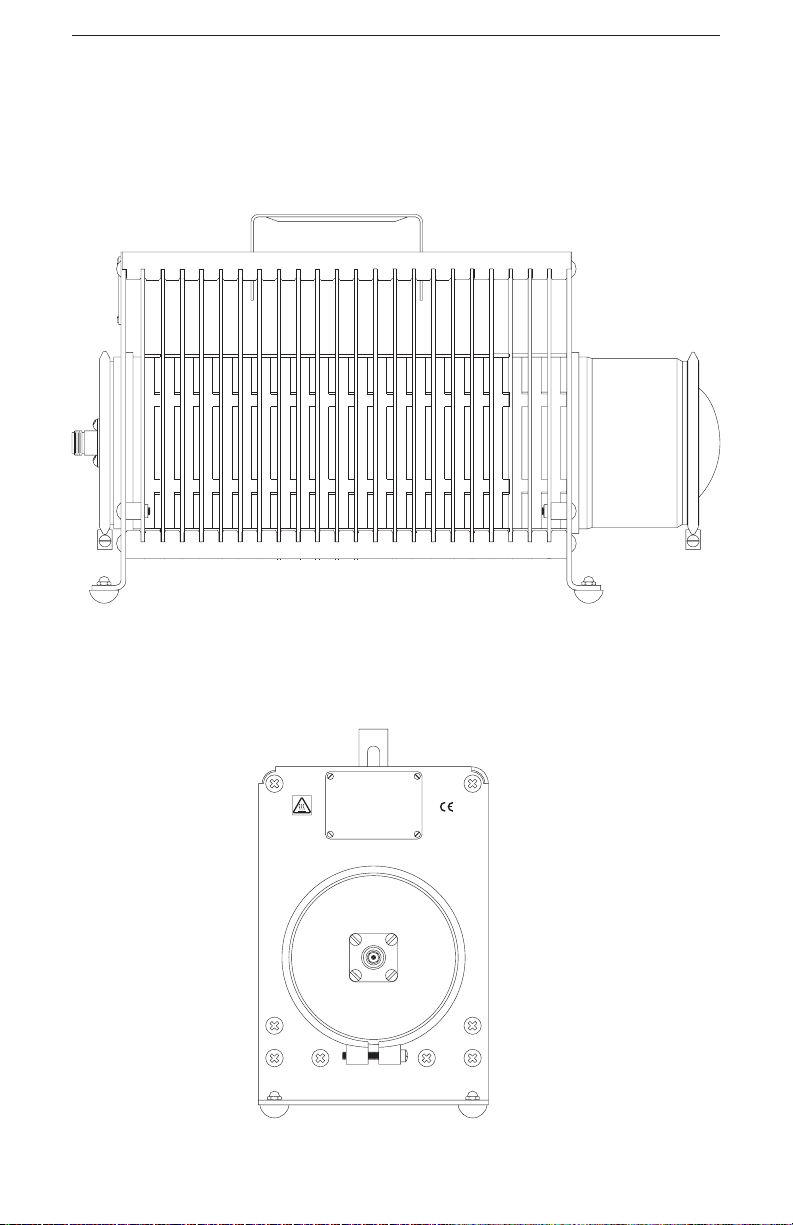
Description These models are rectangular in shape with transverse fins
encasing an oil-dielectric-filled coolant cylinder. A retractable handle is recessed in the radiator fins. Extra thick fins
at the front and rear are bent 90° to form bottom mounting
flanges. These flanges are supports for free standing use or
brackets for fixed mounting. Flange holes are provided for
this purpose.
Performance
Capabilities
and
The Model 8201 Termaline Load Resistor can absorb and
dissipate up to 500 W of RF power continuously over a frequency range of dc to 2500 MHz. It will show a maximum
VSWR of 1.1 to 1.0 from dc to 1000 MHz and 1.25 to 1.0
from 1000 to 2500 MHz.
The Model 8203 Termaline Load Resistor will take a load of
up to 600 W, over a frequency range of dc to 1000 MHz. Its
1
Page 12

Bird Models 8201 & 8203 Termaline Coaxial Load Resistor
maximum VSWR rating is 1.1 to 1.0 over this frequency
range.
Note: The specifications for the Model 8203 ap-
+
ply only as long as the ambient temperature
remains at 30°C (+86°F) or lower.
Dimensions
and Weight
Power and
Requirements
Environmenta
Requirements
Utility
Items
Supplied
The Models 8201 and 8203 are 16-13/16 inches L x 5-15/16
inches W x 8-1/2 inches H (427 x 151 x 216 mm). They have
a net weight of 20.4 lb (9.2 kg) and a shipping weight of approximately 26 lb (12 kg).
As load resistors, the Models 8201 and 8203 are passive devices that are self contained and do not require a source of
power or utility service to perform their function, other than
the RF input power.
The load should be operated in an environment as free of
l
dust and vibration as possible. For proper operation the ambient temperature should remain within the range of -40°C
to +45°C (-40°F to +113°F) for Model 8201 and -40°C to
+30°C (-40°F to +86°F) for Model 8203. Allow at least six
inches of clear space around the load to provide an unimpeded flow of convection air currents for adequate heat dissipation.
The load is equipped with:
s Model 8201 — Female N connector of a pat-
ented “Quick-Change” design.
s
Instruction Manual.
s
Model 8203 — Double Male N adapter, and a
connector dust cap.
s
Instruction Manual.
Required
Tools and
Equipment
2
Items
Test
Because these load resistors are self contained, they have no
additional parts.
Only a coaxial cable with the appropriate connector plug
(normally a Male N or, with the Model 8203, a Female N), is
needed for connecting these load resistors to the source of
RF power.
s
Screwdrivers — for disassembly of this equipment.
s
An ohmmeter with an accuracy of 1 percent or
better at 50 ohms is recommended for checking the resistance value of the resistor.
Page 13

Introduction
Specifications
Impedance 50 ohms nominal
VSWR:
Model 8201: 1000-2500 MHz
Model 8203: dc-1000 MHz
Connectors: Female N “QC” type normally supplied
Power Range
Model 8201
Model 8203
Frequency Range
Model 8201
Model 8203
Dimensions 16-13/16"L x 5-15/16" W x 8-1/2"H
Ambient Temperature
Model 8201
Model 8203
Coolant Method Convention air currents
Weight 20.4 lb (9.2 kg)
Operating Position Horizontal only
Finish Grey Powder Coat
1.1:1.0 Maximum
1.25:1.0 Maximum
500 W continuous
600 W continuous
dc-2500 MHz
dc-1000 MHz
(427 x 151 x 216 mm)
-40°C to +45°C (-40°F to +113°F)
40°C to +30°C (-40°F to +86°F)
1
1
Model 8203 also includes a double Male N adapter and a dust cap.
3
Page 14
Bird Models 8201 & 8203 Termaline Coaxial Load Resistor
Figure 1
Model 8201
ELECTRONIC
4240-062
4
Page 15

Chapter 2
Theory of Operation
General The Models 8201 and 8203 Termaline Load Resistor consist
essentially of a carbon film-on-ceramic resistor immersed in
a dielectric coolant. The resistor, individually selected for its
accuracy, is enclosed in a special exponentially tapered
housing. This provides a linear reduction in surge impedance directly proportional to the distance along the resistor.
When surrounded by the dielectric coolant, the characteristic impedance is therefore 50 ohms at the front (connector
end), 25 ohms at the mid-point to compensate for the resistance already passed over, and zero ohms at the rear where
the resistor joins the housing, forming the return conductor
of the coaxial circuit. This produces a uniform and practically reflectionless line termination over the stated frequencies for the load resistor.
Cooling The dielectric coolant is chosen for its desirable dielectric
and thermal characteristics. Cooling of the Models 8201 and
8203 is accomplished by natural fluid and air convection
currents. The 0.7 gallon of dielectric coolant carries the electrically generated heat from the resistor to the walls of the
cylindrical cooling tank. This tank is encased in a set of radiating fins constructed from heavy gauge aluminum alloy
and firmly pressed onto the cylinder. The heat from the dielectric fluid is transferred to the surrounding air by the
fins.
Expansion of the coolant, caused by the rise in its temperature, is allowed by means of a synthetic rubber diaphragm
(not visible) inside the rear cover dome of the unit.
5
Page 16

Bird Models 8201 & 8203 Termaline Coaxial Load Resistor
6
Page 17

Chapter 3
Installation
Location
CAUTION
The load is designed for operation in a horizontal plane
only, with mounting brackets down. Do not operate in
any other position.
Install the Model 8201 or 8203 Termaline Load Resistor in a
location that:
Has sufficient room to provide at least six
s
inches of free space around and above the
unit.
s Is the shortest possible distance, or cable
length from the transmitting equipment.
Ensures the operation of the load in a horizon-
s
tal position only, with the handle on top.
Mounting The load may be used for portable operation or for fixed in-
stallation, that is, it may stand free or may be secured to a
bench or any convenient flat surface. The front and rear fins
are made of heavier gauge material bent outward 90 degrees to form mounting flanges. At each corner of these
flanges is a rubber bumper foot attached with an acorn nut.
To fasten the load by means of its base mounting flanges:
1. Remove the four rubber bumpers
2. Fasten the load with four screws. Put one screw
in each of the four 9/32 inch holes.
Note: Use screws up to 1/4 inch diameter.
The holes are arranged in a 5-1/8 x 12-17/32 inch rectangle
(130.2 x 318.3 mm).
7
Page 18

Bird Models 8201 & 8203 Termaline Coaxial Load Resistor
8
Page 19
Chapter 4
Operating Instructions
Use and
Function of
Controls
Initial
Adjustments
Because these are passive devices, there are no operating
controls on the Models 8201 and 8203 Load Resistors.
No initial adjustments are required other than to connect
the load to the RF source by means of a coaxial cable
equipped with a suitable matching connector plug.
Start-up 1. Connect a Male N type plug, which mates with
the RF input connector, to the load.
2. Connect the Model 8201 or 8203 Termaline Load
Resistor to the transmitting equipment under
test with 50 ohm coaxial cable.
3. After the transmitter has been connected to the
load, proceed according to the transmitter manufacturer’s instructions.
When reconnecting the antenna, it may become necessary to
slightly readjust the transmitter due to possible differences
in VSWR between the load and the antenna system.
Normal
Operation
WARNING
When power is in the upper range of the load’s
capacity, the radiator will become hot - care should be
used in touching the equipment.
Operating
Under
Emergency,
Adverse, or
Abnormal
Conditions
Having no indicators or controls, these loads require no special operating procedures or surveillance when properly
used.
CAUTION
Do not operate this equipment continuously above the
rated 500 W for Model 8201, or 600 W for Model 8203.
Load failure will result.
9
Page 20

Bird Models 8201 & 8203 Termaline Coaxial Load Resistor
Shutdown Because both the Models 8201 and 8203 are passive devices,
there is no way to turn them off. Power must be shut off at
the source of the RF energy.
Emergency
Shutdown
WARNING
Do not attempt to disconnect these loads from the
coaxial cable while RF energy is still being applied.
Leaking RF power is a potential health hazard.
Turn off the RF power at the source.
10
Page 21

Chapter 5
This chapter contains operator maintenance instructions,
troubleshooting, and parts information.
Troubleshooting
Problem Possible Cause Remedy
Leakage of coolant oil
around band or radiator
housing.
Overheating of the radiator.
High or low dc resistance values.
Maintenance
Clamping band not
tight.
Faulty o-ring (front). Replace per the RF
Faulty diaphragm (rear). Replace per the Dia-
Transmitter power is
too high.
Coolant level is too low. Add more coolant per
Faulty RF section. Replace the RF section
Faulty RF input connector.
Loose RF input connector.
Faulty RF section assembly.
Tighten clamping band
with a screwdriver.
Load Resistor paragraph.
phragm and Coolant Oil
paragraph.
Reduce the transmitter
power.
the Diaphragm and
Coolant Oil paragraph.
per the RF Load Assembly paragraph.
Replace per the RF
connector replacement
paragraph.
Tighten the connector
with a screwdriver.
Replace the RF section
per the RF Load Assembly paragraph.
Cleaning
The principle maintenance required by the operator will be
the cleaning of the radiator fins. Periodically wipe away the
accumulated dust and lint. If the insulator or metallic contact surfaces of the connector should become dirty or grimy,
wipe them off with a soft cloth and use a contact cleaner
that is self drying and leaves no residue to clean the inaccessible internal parts.
11
Page 22
Bird Models 8201 & 8203 Termaline Coaxial Load Resistor
Inspection With the rugged and simple construction of the Models 8201
and 8203 Load Resistors, periodic inspection will be necessary at only about six-month intervals. Inspection should include the items listed below:
1. Oil Leakage - Check for coolant oil seepage
around the radiator tank, particularly at the
front and back around the underside of the
clamping band.
2. Inspect the Load for completeness and general
condition of the equipment.
The Troubleshooting Chart lists the symptoms of commonly
encountered troubles, their causes, and suggested corrective
measures. Use the chart as a guide when analyzing symptoms.
Preventive
Maintenance
Resistance
Measurement
DC
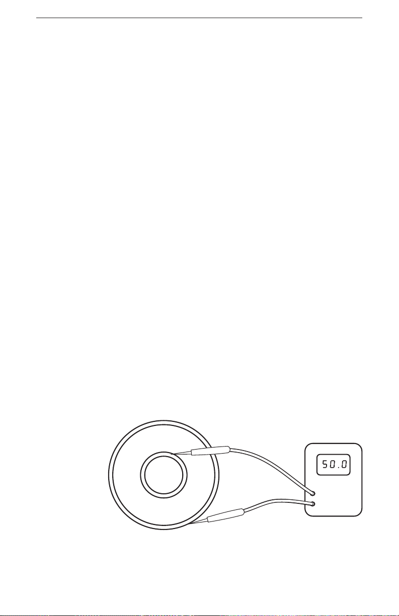
Figure 2
DC
Resistance
Because of the basic simplicity of construction, no special
maintenance procedures are required. Keep the equipment
clean, and occasionally check the coolant level in the radiator tank.
Check the condition of the load resistor by accurate measurement of the dc resistance between the inner and outer
conductors of the RF connector. Use an ohmmeter with an
accuracy of 1 percent or better at 50 ohms for this purpose.
The measured resistance should be a nominal 50 ohms, ±2
ohms. Perform this test only when the load has cooled down
to room temperature. Refer to figure 2.
12
Page 23

Maintenance
Disassembly
There are no special techniques required for the repair or
replacement of components in the Models 8201 and 8203
loads. A screwdriver is the only tool needed.
RF Connector
Replacement
Diaphragm
and Coolant
Oil
The connector is a patented “Quick Change” design which
permits easy interchange with the use of only a screwdriver.
This process does not interfere with the essential coaxial
continuity of the load resistor RF input or the coolant oil
seal. For replacement, proceed as follows:
1. Remove the four 8-32 x 5/16 inch round head
machine screws from the corners of the RF connector.
2. Pull the connector straight out of its socket.
Remove the diaphragm to replace or examine the coolant
oil. Replacement of the diaphragm and coolant are listed in
the steps below:
1. Stand the load vertically, with the back end up.
Brace it carefully to avoid tipping it over.
2. Loosen the clamp screw until the clamping band
is released.
3. Remove the diaphragm cover and lift the diaphragm from the back end of the radiator tank.
Inspect the diaphragm. It should be soft and pliable. If it has hardened or shows signs of surface
cracks, replace it.
4. The coolant oil level should be about one inch below the top of the radiator cylinder. If the oil appears to be contaminated; i.e., it doesn’t have a
clear light yellow color, replace it.
RF Load
Resistor
Assembly
To replace the load resistor assembly, it is not necessary to
drain the unit of coolant oil. Follow the steps below:
1. Stand the load vertically, with the front end up.
2. Loosen the clamp screw until the clamping band
is released.
3. Hold the load assembly by the RF connector and
pull the assembly slowly out of the radiator. Allow the excess coolant to drip back into the radiator.
13
Page 24

Bird Models 8201 & 8203 Termaline Coaxial Load Resistor
4. Inspect the O-Ring seal which is located just inside the mounting flange of the resistor assembly.
Do not reuse the O-Ring if it is not soft and pliable or if it shows signs of surface cracks.
Assembly
RF Connector Before pushing the RF connector in, be sure that the pro-
jecting center contact pin on the connector is carefully engaged and properly seated in the mating socket of the load
resistor input.
Install the four 8-32 x 5/16 inch round head machine screws
into the corners of the RF connector.
Diaphragm
and Coolant
Oil
RF Load
Resistor
Assembly
To assemble, follow the instructions below.
1. Fill the unit with coolant until the level is about
one inch below the top of the radiator cylinder.
2. Install the diaphragm and place the diaphragm
cover on the back end of the radiator tank.
3. Install and tighten the clamping band screw.
4. Check for leaks. Pay particularly close attention
to the area around the clamping band.
To install the assembly:
1. Hold the load assembly by the RF connector and
slowly lower the assembly into the radiator
2. Place the clamp band on and tighten the clamp
screw until the clamping band is tight.
3. Place the unit on its flanges, in a horizontal position.
4. Check for leaks. Pay particularly close attention
to the area around the clamping band.
REPAIRS
Preparation
For Shipment
14
Any maintenance or service procedure beyond the scope of
those provided in this section should be referred to a qualified service center.
Wrap and tape the RF connector to keep out foreign material, then pack and brace the load in a suitable container. A
sturdy corrugated paper box is recommended.
Page 25

Storage No special preparations are needed for storage other than to
cover the equipment to keep out dust and dirt. Store the
unit in a clean dry environment where the ambient temperature will remain within the approximate working range of
the instrument -40°C to +45°C (-40°F to +113°F) for Model
8201 and -40°C to +30°C (-40°F to +86°F) for Model 8203.
Customer Service
Sales /Repair
Facilities
Sales
Facilities
U.S.A Sales and Manufacturing
Service Group
Bird Electronic Corporation
30303 Aurora Rd
Cleveland (Solon). Ohio 44139-2794
Phone: (440) 248-1200
Fax: (440) 248-54-26
For the location of the sales office nearest you give us a call,
or visit our Web site at
http://www.bird-electronic.com
15
Page 26

Replacement Parts List
Models 8201/03
Item Qty. Description Part Number
1
2
3 .7 gal
4
5
6
7
8
9
10
11
12
13
1
1
(2.65 liters)
1
1
1
2
1
4
4
1
1
1
Radiator assembly 2430-050
RF Section assembly 8205-002
Dielectric coolant 5-030-3
“QC” connector *see below
Diaphragm 2430-015
Diaphragm cover 2430-148
Clamp band 2430-043
O-Ring seal 8110-039
Bumper foot 5-049
Acorn nut 8110-171
Radiator handle 2430-028
Adapter and chain assembly 8203-003
Dust cap (model 8203) 5-297
*Available QC Type Connectors
N-Female 4240-062 LT-Female 4240-018
N-Male 4240-063 LT-Male 4240-012
HN-Female 4240-268 C-Female 4240-100
HN-Male 4240-278 C-Male 4240-110
LC-Female 4240-031 UHF-Female
4240-050
(SO-239)
LC-Male 4240-025 UHF-Male
4240-179
(PL-259)
7/8" EIA Air Line 4240-002
16
Page 27

Maintenance
LIMITED WARRANTY
All products manufactured by Seller are warranted to be free from defects in
material and workmanship for a period of one (1) year, unless otherwise specified, from date of shipment and to conform to applicable specifications, drawings, blueprints and/or samples. Seller’s sole obligation under these
warranties shall be to issue credit, repair or replace any item or part thereof
which is proved to be other than as warranted; no allowance shall be made
for any labor charges of Buyer for replacement of parts, adjustment or repairs, or any other work, unless such charges are authorized in advance by
Seller.
If Seller’s products are claimed to be defective in material or workmanship or
not to conform to specifications, drawings, blueprints and/or samples, Seller
shall, upon prompt notice thereof, either examine the products where they
are located or issue shipping instructions for return to Seller (transportation-charges prepaid by Buyer). In the event any of our products are proved
to be other than as warranted, transportation costs (cheapest way) to and
from Seller’s plant, will be borne by Seller and reimbursement or credit will
be made for amounts so expended by Buyer. Every such claim for breach of
these warranties shall be deemed to be waived by Buyer unless made in writing within ten (10) days from the date of discovery of the defect.
The above warranties shall not extend to any products or parts thereof which
have been subjected to any misuse or neglect, damaged by accident, rendered
defective by reason of improper installation or by the performance of repairs
or alterations outside of our plant, and shall not apply to any goods or parts
thereof furnished by Buyer or acquired from others at Buyer’s request and/or
to Buyer’s specifications. In addition, Seller’s warranties do not extend to the
failure of tubes, transistors, fuses and batteries, or to other equipment and
parts manufactured by others except to the extent of the original manufacturer’s warranty to Seller.
The obligations under the foregoing warranties are limited to the precise
terms thereof. These warranties provide exclusive remedies, expressly in lieu
of all other remedies including claims for special or consequential damages.
SELLER NEITHER MAKES NOR ASSUMES ANY OTHER WARRANTY
WHATSOEVER, WHETHER EXPRESS, STATUTORY, OR IMPLIED, INCLUDING WARRANTIES OF MERCHANTABILITY AND FITNESS, AND
NO PERSON IS AUTHORIZED TO ASSUME FOR SELLER ANY OBLIGATION OR LIABILITY NOT STRICTLY IN ACCORDANCE WITH THE
FOREGOING.
17
 Loading...