


4421-RF

INSTRUCTION BOOK
THRULINE® RF POWER METER MODEL 4421
AND
THRULINE
4027F SERIES, AND 4028 SERIES
®
DIRECTIONAL RF POWER SENSORS
4020 SERIES, 4027A SERIES,
©Copyright 2004 by Bird Electronic Corporation
Instruction Book Part Number 920-4421 Rev L
®
Thruline
is a Registered Trademark
of Bird Electronic Corporation

This page intentionally left blankiSafety Precautions

The following are general safety precautions that are not necessarily
related to any specific part or procedure and do not necessarily appear
elsewhere in this publication. These precautions must be thoroughly
understood and apply to all phases of operation and maintenance.
Keep Away From Live Circuits
Operating personnel must at all times observe normal safety regulations.
Do not replace components or make adjustments inside the equipment
with high voltage turned on. To avoid casualties, always remove power.
Shock Hazard
Do not attempt to remove the RF transmission line while RF power is
present.
Do Not Service or Adjust Alone
Under no circumstances should any person reach into an enclosure for the
purpose of service or adjustment of equipment except in the presence of
someone who is capable of rendering aid.
Safety Earth Ground
An uninterruptible earth safety ground must be supplied from the main
power source to test instruments. Grounding one conductor of a two
conductor power cable is not sufficient protection. Serious injury or death
can occur if this grounding is not properly supplied.
Chemical Hazard
Dry cleaning solvents for cleaning parts may be potentially dangerous.
Avoid inhalation of fumes or prolonged contact with skin.
Resuscitation
Personnel working with or near high voltages should be familiar with
modern methods of resuscitation.
Bird 4421 RF Power Meter
Safety Symbols
WARNING
Warning notes call attention to a procedure which, if not correctly
performed, could result in personal injury.
CAUTION
Caution notes call attention to a procedure which, if not correctly
performed, could result in damage to the instrument.
The caution symbol appears on the equipment indicating there
is important information in the instruction manual regarding
that particular area. See pages 2, 6, 45, 47, and page 52 for
specific cautions.
NOTE: Calls attention to supplemental information.
Warning Statements
The following safety warnings appear in the text where there is danger to
operating and maintenance personnel and are repeated here for emphasis.
WARNING
Never attempt to connect or disconnect RF equipment from the
transmission line while RF power is being applied.
Leaking RF energy is a potential health hazard.
WARNING
The Bird 4421 contains no user-serviceable parts.
Do not remove its cover.
WARNING
To avoid personal injury, disconnect the power cord from the ac line
before performing any maintenance, including fuse replacement or
changing the line voltage setting.
Caution Statements
The following equipment cautions appear in the text whenever the
equipment is in danger of damage and are repeated here for emphasis.
CAUTION
The interface module contains electrostatic discharge (ESD)
sensitive components. Failure to observe ESD precautions can
cause permanent damage.
ii
CAUTION
Changing the sensor’s connectors will invalidate calibration data,
and may reduce the maximum power rating of the unit.
CAUTION
Be sure that the 115/230 voltage selector on the 4421’s rear panel is set
to the proper voltage before ac power is applied.
CAUTION
The Bird 4421 must be powered off when connecting or
disconnecting the power sensor from the power meter.
CAUTION
Do not use the power sensor with a load VSWR greater then 2:1.
Damage to the power meter, power sensor, or the
RF power source could occur.
CAUTION
During remote operation, periodically monitor the bus
service request line. Failure to detect a service request
could result in equipment damage.
CAUTION
Due to the complexity of the Bird Power Sensor, field repairs
beyond general maintenance should not be attempted.
Removal or disturbance of the power sensor cover can result in
cancellation of lifetime warranty.
CAUTION
Failure to install the properly rated fuse may result in equipment
damage or nuisance failures.
Safety Statements
USAGE
ANY USE OF THIS INSTRUMENT IN A MANNER NOT
SPECIFIED BY THE MANUFACTURER MAY IMPAIR THE
INSTRUMENT’S SAFETY PROTECTION.
USO
EL USO DE ESTE INSTRUMENTO DE MANERA NO ESPECIFICADA
POR EL FABRICANTE, PUEDE ANULAR LA PROTECCIÓN DE
SEGURIDAD DEL INSTRUMENTO.
iii

Bird 4421 RF Power Meter
BENUTZUNG
WIRD DAS GERÄT AUF ANDERE WEISE VERWENDET ALS VOM
HERSTELLER BESCHRIEBEN, KANN DIE GERÄTESICHERHEIT
BEEINTRÄCHTIGT WERDEN.
UTILISATION
TOUTE UTILISATION DE CET INSTRUMENT QUI N’EST PAS
EXPLICITEMENT PRÉVUE PAR LE FABRICANT PEUT
ENDOMMAGER LE DISPOSITIF DE PROTECTION DE
L’INSTRUMENT.
IMPRIEGO
QUALORA QUESTO STRUMENTO VENISSE UTILIZZATO IN MODO
DIVERSO DA COME SPECIFICATO DAL PRODUTTORE LA
PROZIONE DI SICUREZZA POTREBBE VENIRNE COMPROMESSA.
SERVICE
SERVICING INSTRUCTIONS ARE FOR USE BY SERVICE-
TRAINED PERSONNEL ONLY. TO AVOID DANGEROUS
ELECTRIC SHOCK, DO NOT PERFORM ANY SERVICING UNLESS
QUALIFIED TO DO SO.
SERVICIO
LAS INSTRUCCIONES DE SERVICIO SON PARA USO EXCLUSIVO
DEL PERSONAL DE SERVICIO CAPACITADO. PARA EVITAR EL
PELIGRO DE DESCARGAS ELÉCTRICAS, NO REALICE NINGÚN
SERVICIO A MENOS QUE ESTÉ CAPACITADO PARA HACERIO.
WARTUNG
ANWEISUNGEN FÜR DIE WARTUNG DES GERÄTES GELTEN NUR
FÜR GESCHULTES FACHPERSONAL.
ZUR VERMEIDUNG GEFÄHRLICHE, ELEKTRISCHE SCHOCKS, SID
WARTUNGSARBEITEN AUSSCHLIEßLICH VON QUALIFIZIERTEM
SERVICEPERSONAL DURCHZUFÜHREN.
ENTRENTIEN
L’EMPLOI DES INSTRUCTIONS D’ENTRETIEN DOIT ÊTRE
RÉSERVÉ AU PERSONNEL FORMÉ AUX OPÉRATIONS
D’ENTRETIEN. POUR PRÉVENIR UN CHOC ÉLECTRIQUE
DANGEREUX, NE PAS EFFECTUER D’ENTRETIEN SI L’ON N’A PAS
ÉTÉ QUALIFIÉ POUR CE FAIRE.
ASSISTENZA TECNICA
LE ISTRUZIONI RELATIVE ALL’ASSISTENZA SONO PREVISTE
ESCLUSIVAMENTE PER IL PERSONALE OPPORTUNAMENTE
ADDESTRATO. PER EVITARE PERICOLOSE SCOSSE ELETTRICHE
NON EFFETTUARRE ALCUNA RIPARAZIONE A MENO CHE
QUALIFICATI A FARLA.
iv
UNITS ARE EQUIPPED WITH RECHAREABLE BATTERIES.
THESE ARE TO BE REPLACED BY AUTHORIZED SERVICE
PERSONNEL ONLY!!!
LAS UNIDADES VIENEN EQUIPADAS CON BATERIAS
RECARGABLES. ¡¡¡Y SOLAMENTE EL PERSONAL DE SERVICIO
AUTORIZADO PUEDE REEMPLAZARLAS!!!
GERÄTE SIND MIT WIEDER AUFLADBAREN BATTERIEN
BESTÜCKT. BATTERIEN SIND NUR VON QUALIFIZIERTEM
SERICE PERSONAL AUSZUWECHSELN!!!
CES DISPOSITIFS SONT ÉQUIPÉS DE BATTERIES
RECHARGEABLES. SEUL LE PERSONNEL D’ENTRETIEN
AUTORISÉ EST HABILITÉ À LES REMPLACER !
LE UNITÀ SONO DOTATE DI BATTERIE RICARICABILI, CHE
DEVONO DA COME SPECIFICATO DAL PRODUTTORE LA
PROTEZIONE DI SICUREZZA POTREBBE VENIRNE
COMPROMESSA.
BE SURE THE 115/230V AC VOLTAGE SELECTOR IS SET
TO THE PROPER LINE VOLTAGE, AND THE CORRECT AC
LINE FUSE IS INSTALLED BEFORE AC POWER IS
APPLIED.
S’ASSURER QUE LE SÉLECTEUR DE TENSION 115/230V C.A. EST
BIEN RÉGLÉ POUR LA TENSION DU RÉSEAU ET QUE LE FUSIBLE
DE LIGNE C.A. CORRECT EST EN PLACE AVANT DE METTRE SOUS
TENSION C.A.
CERCIORESE QUE EL SELECTOR DE VOLTAJE DE 115/230V CA
ESTE COLOCADO A LA LINEA DE VOLTAJE APROPIADA Y QUE EL
FUSIBLE ESTE INSTALADO A LA LINEA CA ANTES DE APLICAR
LA CORRIENTE ALTERNA.
VOR EINSCHALTEN DER WECHSELSTROMZUFUHR
SICHERSTELLEN, DASS DER 115/230V WECHSELSPANNUNGSSELEKTOR AUF DIE VORSCHRIFTSMÄSSIGE
LEITUNGSSPANNUNG EINGESTELLT UND DIE RICHTIGE
WECHSELSTROM-HAUPTSICHERUNG EINGESETZT IST.
PRIMA DI EROGARE CORRENTE, ASSICURARSI CHE IL
SELETTORE DI VOLTAGGIO 115/230 V.C.A. SIA REGOLATO
CORRETTAMENTE E CHE IL FUSIBLE ADATTO ALLA LINEA DI
ALIMENTAZIONE C.A. SIA INSTALLATO.
v

Bird 4421 RF Power Meter
About This Manual
This manual covers the Bird 4421 RF Power Meter, Bird 4020 Series
Power Sensors, Bird 4027A Series Precision Power Sensors, and Bird
4027F Series Precision Filtered Power Sensors. Specific models include:
Power Meter 4421
4020 Series
Sensors
4027A Series
Sensors
4027F Series
Sensors
4028A Series
Sensors
4028B Series
Sensors
4021 4022 4024 4025
4027A250K 4027A400K 4027A800K 4027A2M
4027A4M 4027A10M 4027A12M 4027A25M
4027A35M 4027A60M 4027A100M 4027A150M
4027F2M 4027F10M 4027F60M
4028A250K 4028A400K 4028A2M 4028A3M
4028A4M 4028A10M 4028A25M
4028B10M
This instruction book is arranged so that essential safety information
appears in the front of the book. Reading the Safety Precautions before
operating the equipment is strongly advised.
The remainder of this manual is divided into Chapters and Sections. At
the start of each chapter, a general overview describes its contents.
Operation
First time users should read Chapter 1 – Introduction and Chapter 2 –
Installation to get an overview of equipment capabilities and installation.
Experienced operators can refer to Chapter 3 – Operating Instructions.
All instructions necessary to manually operate the equipment appear in
this chapter. If the power meter is equipped with a IEEE-488 GPIB
Interface refer to Chapter 4 – IEEE-488 GPIB Interface. For the RS-232
Interface refer to Chapter 5 – RS-232 Interface.
Maintenance
All personnel should be familiar with preventative maintenance found in
Chapter 6 – Maintenance. If a failure should occur, the troubleshooting
section will aid in isolating and repairing the failure. A list of
replacement parts with part numbers is also in this chapter.
vi

Changes To This Manual
We have made every effort to ensure this manual is accurate. If you
should discover any errors, or if you have suggestions for improving this
manual, please send your comments to our factory. This manual may be
periodically updated. When inquiring about updates to this manual refer
to the part number and revision level on the title page.
vii

Table of Contents
Safety Precautions . . . . . . . . . . . . . . . . . . . . . . . . . . . . i
About This Manual . . . . . . . . . . . . . . . . . . . . . . . . . . . vi
Introduction . . . . . . . . . . . . . . . . . . . . . . . . . . . . . . . . 1
Power Meter . . . . . . . . . . . . . . . . . . . . . . . . . . . . . . . . . . . . . . . . . . . . . . . . . . . . 1
Items Supplied . . . . . . . . . . . . . . . . . . . . . . . . . . . . . . . . . . . . . . . . . . . . . . . 1
Optional Accessories . . . . . . . . . . . . . . . . . . . . . . . . . . . . . . . . . . . . . . . . . . 1
Power Sensors . . . . . . . . . . . . . . . . . . . . . . . . . . . . . . . . . . . . . . . . . . . . . . . . . . 2
4020 Series. . . . . . . . . . . . . . . . . . . . . . . . . . . . . . . . . . . . . . . . . . . . . . . . . . 2
4027A Series . . . . . . . . . . . . . . . . . . . . . . . . . . . . . . . . . . . . . . . . . . . . . . . . 2
4027F Series. . . . . . . . . . . . . . . . . . . . . . . . . . . . . . . . . . . . . . . . . . . . . . . . . 3
4028 Series. . . . . . . . . . . . . . . . . . . . . . . . . . . . . . . . . . . . . . . . . . . . . . . . . . 3
Frequency and Power Ranges . . . . . . . . . . . . . . . . . . . . . . . . . . . . . . . . . . . . . . 3
4020 Series. . . . . . . . . . . . . . . . . . . . . . . . . . . . . . . . . . . . . . . . . . . . . . . . . . 3
4027A Series . . . . . . . . . . . . . . . . . . . . . . . . . . . . . . . . . . . . . . . . . . . . . . . . 4
4027F Series. . . . . . . . . . . . . . . . . . . . . . . . . . . . . . . . . . . . . . . . . . . . . . . . . 4
4028 Series. . . . . . . . . . . . . . . . . . . . . . . . . . . . . . . . . . . . . . . . . . . . . . . . . . 4
Installation. . . . . . . . . . . . . . . . . . . . . . . . . . . . . . . . . 5
Interface Module . . . . . . . . . . . . . . . . . . . . . . . . . . . . . . . . . . . . . . . . . . . . . . . . . 5
Sensor Connection . . . . . . . . . . . . . . . . . . . . . . . . . . . . . . . . . . . . . . . . . . . . . . . 6
RF Line Connection . . . . . . . . . . . . . . . . . . . . . . . . . . . . . . . . . . . . . . . . . . . . . . 6
Handle Operation . . . . . . . . . . . . . . . . . . . . . . . . . . . . . . . . . . . . . . . . . . . . . . . . 6
115/230V AC Power Selection . . . . . . . . . . . . . . . . . . . . . . . . . . . . . . . . . . . . . . 7
Setting AC Voltage . . . . . . . . . . . . . . . . . . . . . . . . . . . . . . . . . . . . . . . . . . . . 7
AC Line Connectors . . . . . . . . . . . . . . . . . . . . . . . . . . . . . . . . . . . . . . . . . . . 7
Operating Instructions . . . . . . . . . . . . . . . . . . . . . . . . . . 9
Push Button Functions . . . . . . . . . . . . . . . . . . . . . . . . . . . . . . . . . . . . . . . . . . . . 9
Error Codes . . . . . . . . . . . . . . . . . . . . . . . . . . . . . . . . . . . . . . . . . . . . . . . . . . . 10
Audible Warning . . . . . . . . . . . . . . . . . . . . . . . . . . . . . . . . . . . . . . . . . . . . . . . . 10
IEEE-488 GPIB Interface . . . . . . . . . . . . . . . . . . . . . . . . 11
viii
Description . . . . . . . . . . . . . . . . . . . . . . . . . . . . . . . . . . . . . . . . . . . . . . . . . . . . 12
Cable Connector . . . . . . . . . . . . . . . . . . . . . . . . . . . . . . . . . . . . . . . . . . . . . 12

Interface Capabilities. . . . . . . . . . . . . . . . . . . . . . . . . . . . . . . . . . . . . . . . . . 13
Indicators. . . . . . . . . . . . . . . . . . . . . . . . . . . . . . . . . . . . . . . . . . . . . . . . . . . 13
Setup. . . . . . . . . . . . . . . . . . . . . . . . . . . . . . . . . . . . . . . . . . . . . . . . . . . . . . . . . 14
Dip Switch . . . . . . . . . . . . . . . . . . . . . . . . . . . . . . . . . . . . . . . . . . . . . . . . . . 14
Talker-Only Mode . . . . . . . . . . . . . . . . . . . . . . . . . . . . . . . . . . . . . . . . . . . . 14
Command Syntax . . . . . . . . . . . . . . . . . . . . . . . . . . . . . . . . . . . . . . . . . . . . . . . 15
General Bus Commands. . . . . . . . . . . . . . . . . . . . . . . . . . . . . . . . . . . . . . . . . . 16
Device Dependent Commands . . . . . . . . . . . . . . . . . . . . . . . . . . . . . . . . . . . . . 19
RS-232 Interface . . . . . . . . . . . . . . . . . . . . . . . . . . . . . 27
Description . . . . . . . . . . . . . . . . . . . . . . . . . . . . . . . . . . . . . . . . . . . . . . . . . . . . 27
Cable Connector . . . . . . . . . . . . . . . . . . . . . . . . . . . . . . . . . . . . . . . . . . . . . 27
Indicators. . . . . . . . . . . . . . . . . . . . . . . . . . . . . . . . . . . . . . . . . . . . . . . . . . . 27
Setup. . . . . . . . . . . . . . . . . . . . . . . . . . . . . . . . . . . . . . . . . . . . . . . . . . . . . . . . . 28
DIP Switch. . . . . . . . . . . . . . . . . . . . . . . . . . . . . . . . . . . . . . . . . . . . . . . . . . 28
Auto Baud . . . . . . . . . . . . . . . . . . . . . . . . . . . . . . . . . . . . . . . . . . . . . . . . . . 28
Talker-Only Mode . . . . . . . . . . . . . . . . . . . . . . . . . . . . . . . . . . . . . . . . . . . . 29
Command Syntax . . . . . . . . . . . . . . . . . . . . . . . . . . . . . . . . . . . . . . . . . . . . . . . 29
General Bus Commands. . . . . . . . . . . . . . . . . . . . . . . . . . . . . . . . . . . . . . . . . . 30
Device Dependent Commands . . . . . . . . . . . . . . . . . . . . . . . . . . . . . . . . . . . . . 32
Maintenance . . . . . . . . . . . . . . . . . . . . . . . . . . . . . . . 39
Troubleshooting . . . . . . . . . . . . . . . . . . . . . . . . . . . . . . . . . . . . . . . . . . . . . . . . 39
Functional Test . . . . . . . . . . . . . . . . . . . . . . . . . . . . . . . . . . . . . . . . . . . . . . 41
Push Button Test. . . . . . . . . . . . . . . . . . . . . . . . . . . . . . . . . . . . . . . . . . . . . 41
Repair . . . . . . . . . . . . . . . . . . . . . . . . . . . . . . . . . . . . . . . . . . . . . . . . . . . . . . . . 42
Fuse . . . . . . . . . . . . . . . . . . . . . . . . . . . . . . . . . . . . . . . . . . . . . . . . . . . . . . 42
Customer Service . . . . . . . . . . . . . . . . . . . . . . . . . . . . . . . . . . . . . . . . . . . . . . . 43
Specifications . . . . . . . . . . . . . . . . . . . . . . . . . . . . . . . . . . . . . . . . . . . . . . . . . . 44
Replacement Parts . . . . . . . . . . . . . . . . . . . . . . . . . . . . . . . . . . . . . . . . . . . . . . 52
Available Connectors . . . . . . . . . . . . . . . . . . . . . . . . . . . . . . . . . . . . . . . . . . . . 52
ix

x

Chapter 1 Introduction
Power Meter
The Bird 4421 RF Power Meter is one component of a complete RF
power measurement system. An RF power sensor such as a Bird 4021
is also required. The system can be controlled with the front panel
buttons, or remotely with the optional interfaces.
Items Supplied y Bird 4421 RF Power Meter
y AC Power Cord
y Sensor Cable
y Instruction Manual
Optional
Accessories
Panel Mount Kit (P/N 4421-250): Allows the Bird 4421 to be installed
in a standard 19" panel for rack mount applications.
IEEE-488 GPIB Bus Interface Module (P/N 4421-488): Allows the 4421
to be remotely controlled over an IEEE-488 general purpose interface
bus (GPIB). A GPIB controller, usually a computer, can then give
commands and read data.
RS-232 Bus Interface Module (P/N 4421-232): Allows the 4421 to be
remotely controlled over an RS-232 interface. A computer or terminal
can then give commands and read data.
Null Modem Kit (P/N 4380-250): Contains the hardware necessary to
allow the 4421 to be remotely controlled by controllers with different
wiring arrangements. Requires an RS-232 interface module.
1
Bird 4421 RF Power Meter
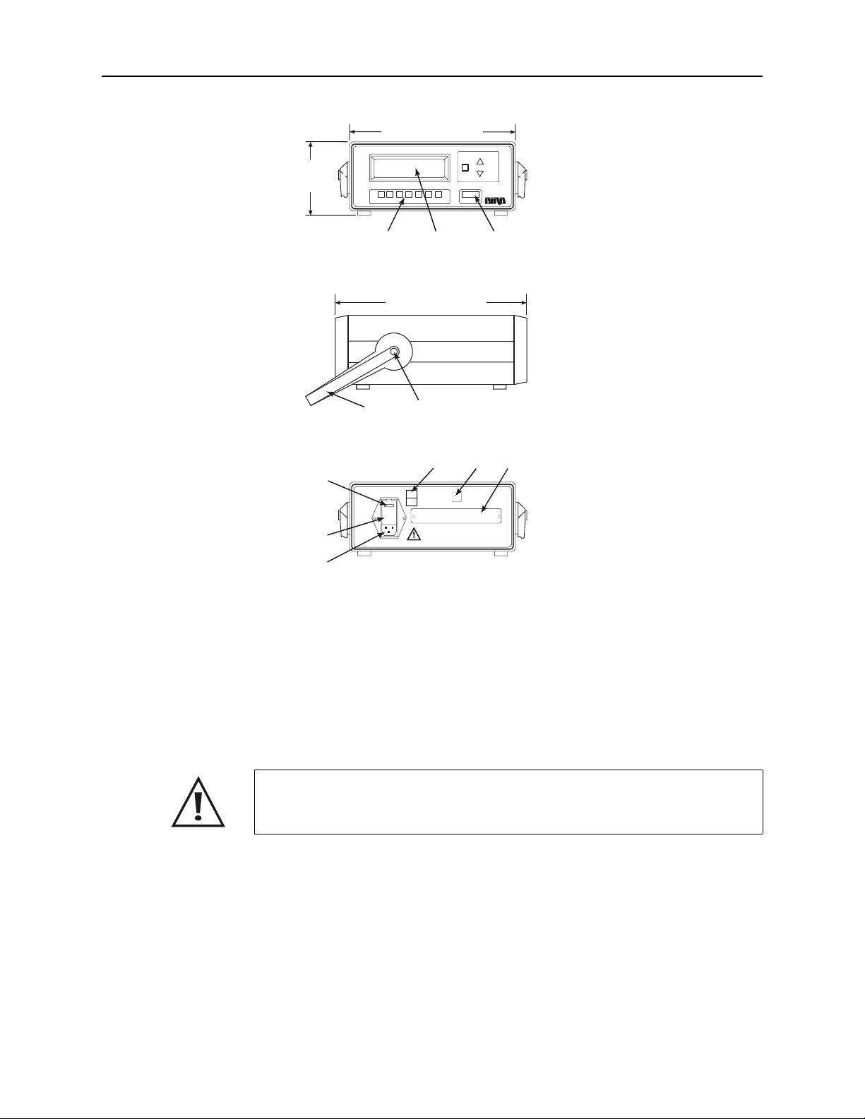
Figure 1
Bird 4421 Meter
Outline Drawing
4-1/4”
(108 mm)
8
10-1/8” (257 mm)
MODEL 4421 RF POWER METER
SWRRFLFWD MIN MAX dBm L IGHT ON / OFF
12
FRONT
12-1/4” (312 mm)
4
5
SIDE
910
1 ON
FUSE
0 OFF
AUTO
POWER
SENSOR
RANGE
UP
DOWN
1. Operating Push Buttons
2. LCD
3. ON/OFF Push Button
3
4. Handle
5. Central Button
6. AC Line Module
7. Access Door
8. Voltage Selector
9. Master ON/OFF Switch
10. Power Sensor Socket
11. Interface Module Access
11
7
6
AC SUPPLY
REAR
Power Sensors
Power sensors are available with a variety of connectors; see
“Available Connectors” on page 52 for a complete list. Since the
accuracy is critically dependent on the connectors used at calibration,
do not remove or change the connectors.
CAUTION
Changing the sensor’s connectors will invalidate calibration data,
and may reduce the maximum power rating of the unit.
4020 Series Bird 4020 Series Power Sensors are designed for lab or field use and
are accurate to within ±3%(1
4027A Series Bird 4027A Series Power Sensors are designed for use in
semiconductor processing and calibration applications. Stringent
calibration provides long-term unit-to-unit repeatability, allowing
consistent amounts of RF energy to be applied to the etch process
over many etch cycles. 4027A Sensors are accurate to ±1%(1
specified calibration frequencies and power levels.
σ) of reading.
σ) at
2
Introduction
(
)
4027F Series
Bird 4027F Series Power Sensors are similar to the 4027A series.
However, additional filtering allows the 4027F to ignore harmonics of
the signal being measured. The 4027F is also less sensitive to AM
components of the signal. 4027F Sensors are accurate to ±1%(2
specified calibration frequencies and power levels.
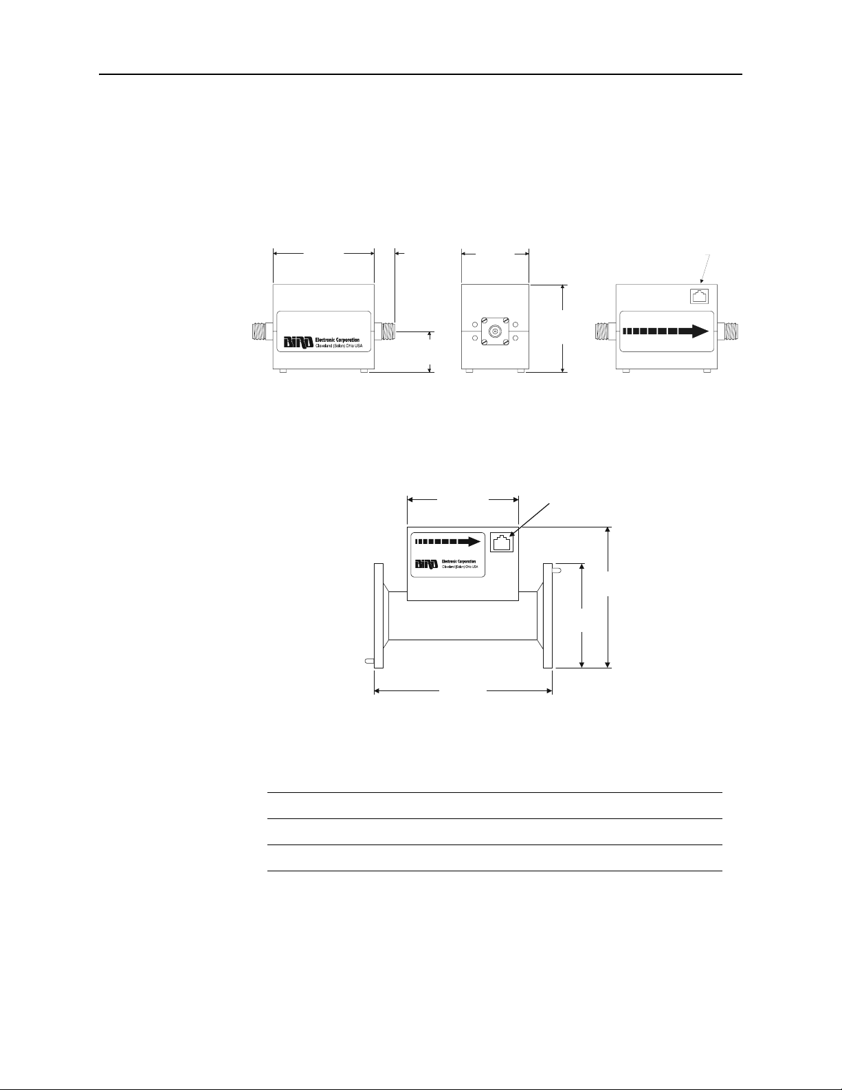
Figure 2
Power Sensor
Outline Drawing,
4020, 4027A, 4027F,
3-3/4”
(95 mm)
and 4028A Series
DIRECTIONAL POWER SENSOR
MODEL 4022
0.3 - 1000 WATTS
25 - 1000 MHz
4028 Series Bird 4028 Series Power Sensors are high power sensors otherwise
3/4”
(19 mm)
1-3/8”
(35 mm)
2-1/2”
(64 mm)
3-1/4”
(83 mm)
SOURCE LOAD
similar to the 4027A series. 4028A sensors are based on a 7/8” line,
while 4028B sensors use a 1-5/8” line. 4028 Sensors are accurate to
±2%(2
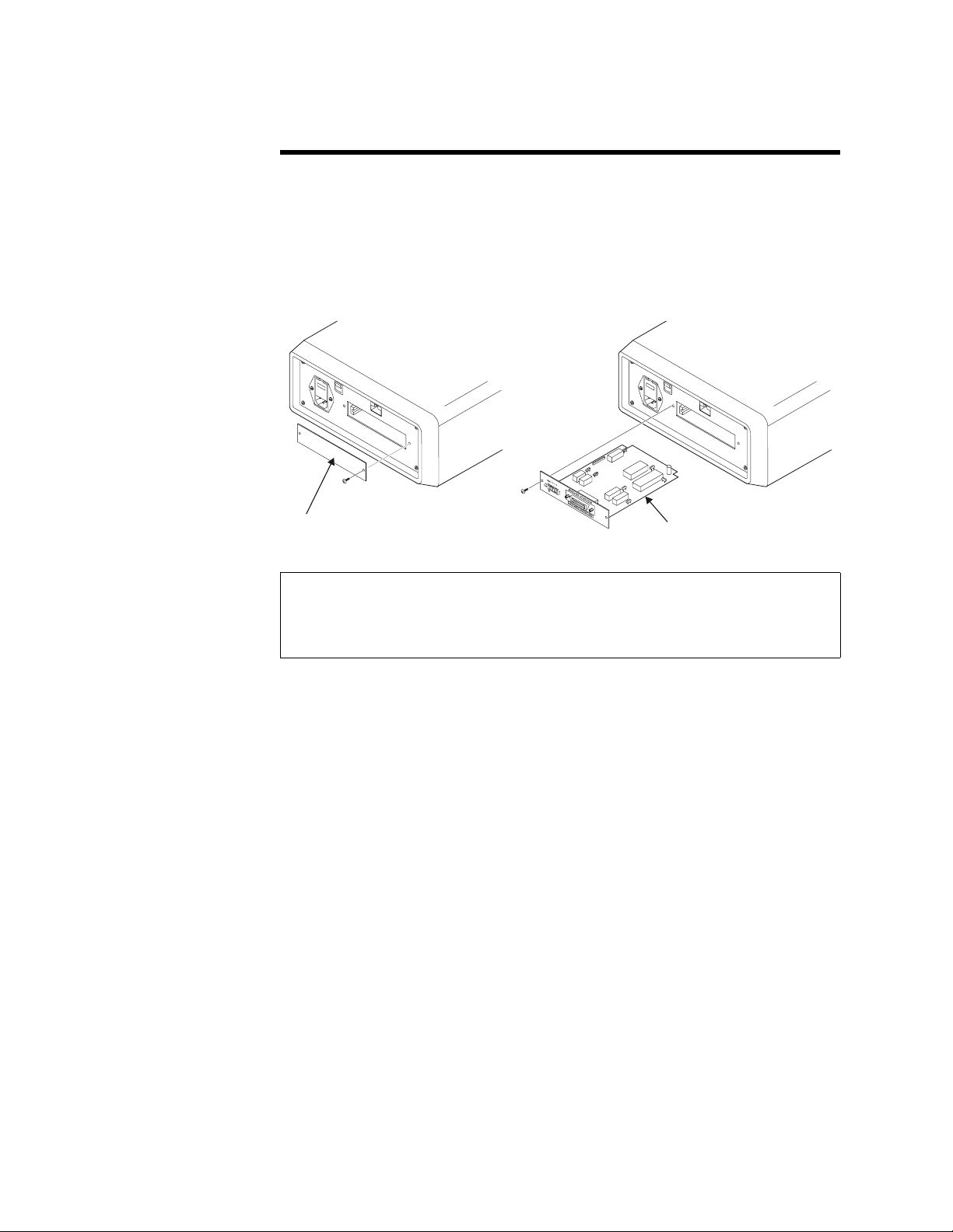
Figure 3
Power Sensor
Outline Drawing
4028B Series only
σ) at specified calibration frequencies and power levels.
3.75"
(96 mm)
SOURCE LOAD
SENSOR PLUG
SOCKET
σ) at
SENSOR PLUG
SOCKET
-CAUTION-
Frequency and Power Ranges
4020 Series
Model Frequency Range RF Power Range
4021 1.8 – 32 MHz 300 mW – 1 kW
4022 25 – 1000 MHz 300 mW – 1 kW
4024 1.5 – 32 MHz 3 W – 10 kW
4025 100 kHz – 2.5 MHz 3 W – 10 kW
6.75"
172 mm
3.5"
(89 mm)
4.75"
(121 mm)
3

Bird 4421 RF Power Meter
4027A Series
4027F Series
4027A250K 250 – 400 kHz 3 W – 10 kW
4027A400K 400 – 550 kHz 3 W – 10 kW
4027A800K 800 – 950 kHz 3 W – 10 kW
4027A2M 1.5 – 2.5 MHz 3 W – 10 kW
4027A4M 3 – 5 MHz 3 W – 10 kW
4027A10M 10 – 15 MHz 3 W – 10 kW
4027A12M 10 – 15 MHz 300 mW – 1 kW
4027A25M 25 – 30 MHz 3 W – 9 kW
4027A35M 35 – 45 MHz 3 W – 7.5 kW
4027A60M 45 – 65 MHz 3 W – 6 kW
4027A100M 95 – 105 MHz 3 W – 5 kW
4027A150M 150 – 170 MHz 3 W – 4 kW
4027F2M 1.8 – 2.2 MHz 100 W – 10 kW
4027F10M 12 – 15 MHz 100 W – 10 kW
4027F60M 57 – 63 MHz 100 W – 3 kW
4028 Series
4028A250K 250 – 400 kHz 1 kW – 20 kW
4028A400K 400 – 550 kHz 1 kW – 20 kW
4028A2M 1.5 – 2.5 MHz 1 kW – 25 kW
4028A3M 2.5 – 3.5 MHz 1 kW – 25 kW
4028A4M 3.5 – 4.5 MHz 1 kW – 25 kW
4028A10M 10 – 15 MHz 1 kW – 25 kW
4028A25M 25 – 30 MHz 1 kW – 25 kW
4028B10M 10 – 15 MHz 1 kW – 25 kW
4
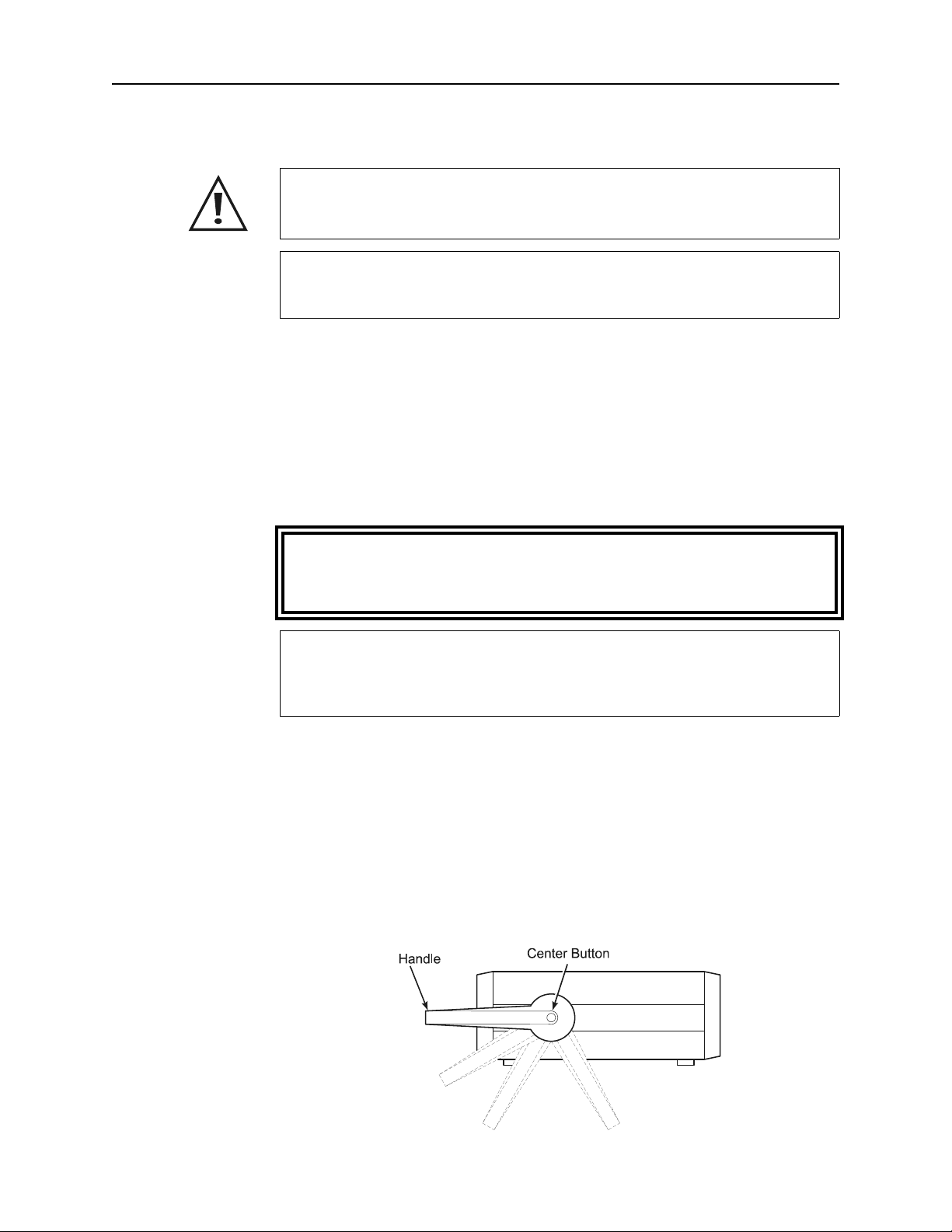
Interface Module
ODU
Figure 4
Interface Module
Installation
Chapter 2 Installation
This chapter provides information on preparing the Bird 4421 for use.
INTERFACE MODULE
ACCESS COVER
INTERFACE
M
LE
CAUTION
The interface module contains electrostatic discharge (ESD)
sensitive components. Failure to observe ESD precautions can
cause permanent damage.
To use the Bird 4421 remotely, the optional interface module must be
installed (see Figure 4):
1. Unscrew and remove the interface access cover on the power
meter’s rear panel.
2. Remove the interface module from its conductive bag.
3. Align the module edges with the side guides in the meter and
slide the interface module into the access slot.
4. Press on the front edge of the module until it seats fully.
5. Screw the module into place with the access cover screws.
6. Connect the power meter to a suitable controller using the cable
supplied with the interface module.
5
Bird 4421 RF Power Meter
Sensor Connection
Changing the sensor’s connectors will invalidate calibration data,
1. Turn OFF the ON/OFF rocker switch on the meter’s rear panel.
2. Align the latch on the cable with the notch of the “Power Sensor”
3. Insert the cable until it clicks into place.
4. Connect the other end of the sensor cable to the sensor.
RF Line Connection
CAUTION
and may reduce the maximum power rating of the unit.
CAUTION
The Bird 4421 must be powered off when connecting or
disconnecting the power sensor from the power meter.
socket on the power meter’s rear panel.
Connect the end of the power sensor labeled “SOURCE” to the RF
source. Connect the end labeled “LOAD” to the load or antenna.
Reversing these connections will cause measurement errors.
Handle Operation
The handle on the Bird 4421 can be set to four different positions (see
Figure 5). To adjust the handle, press the center buttons on both
sides. Releasing the buttons will lock the handle into position.
Figure 5
Handle Positions
WARNING
Never attempt to connect or disconnect RF equipment from the
transmission line while RF power is being applied.
Leaking RF energy is a potential health hazard.
CAUTION
Do not use the power sensor with a load VSWR greater then 2:1.
Damage to the power meter, power sensor, or the
RF power source could occur.
6
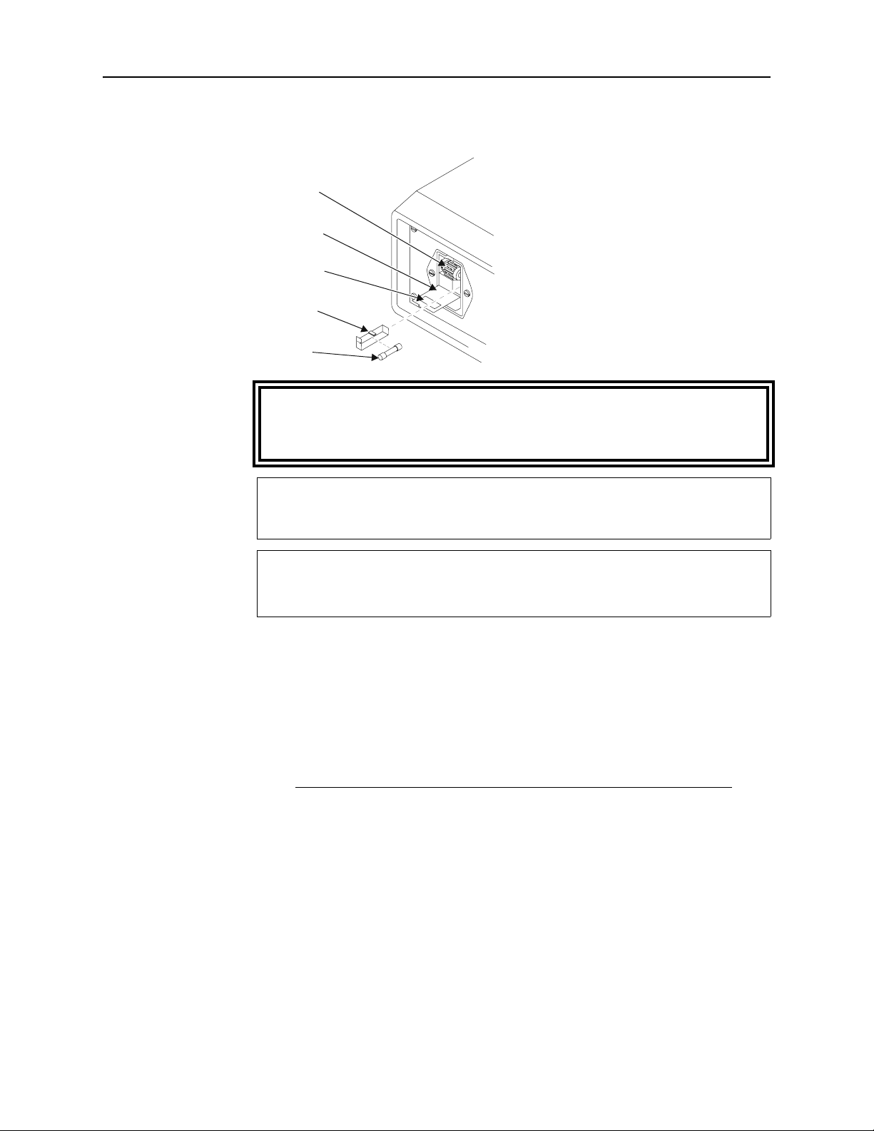
115/230V AC Power Selection
A
Figure 6
Voltage Selection
Selector
Drum
C Module
Door
Selection
Window
Fuse
Drawer
Fuse
To avoid personal injury, disconnect the power cord from the ac line
before performing any maintenance, including fuse replacement or
Installation
WARNING
changing the line voltage setting.
CAUTION
Be sure that the 115/230 voltage selector on the 4421’s rear panel is
set to the proper voltage before ac power is applied.
CAUTION
Failure to install the properly rated fuse may result in equipment
damage or nuisance failures.
Setting AC Voltage The 4421 is factory set for 115 Vac input voltage. To change the
voltage setting:
1. Open the ac module door and remove the fuse drawer and the
voltage selector drum.
2. Install the new fuse and replace the fuse drawer.
AC Line Voltage Fuse Rating
115 Vac T250 mA, 5x20 mm Time Lag Fuse
230 Vac T125 mA, 5x20 mm Time Lag Fuse
3. Rotate the voltage selector drum to the desired voltage:
y For 115 Vac, position the drum so that the second line on the
drum will be visible through the window.
y For 230 Vac, position the drum so that the third line on the
drum will be visible through the window.
4. Replace the voltage selector drum and close the ac module door.
AC Line
Connectors
To make the ac line cord compatible with European style sockets,
users must install the appropriate connector on the power cord.
7

Bird 4421 RF Power Meter
8
 Loading...