


Cytation 5
Cytation™ 5
Cell Imaging Multi-Mode Reader
Instructions for Use
BioTek® Instruments, Inc.
January 2015
© 2015
PN 1321022
Revision A

ii | Preface
Notices
BioTek® Instruments, Inc.
Highland Park, P.O. Box 998
Winooski, Vermont 05404-0998 USA
All Rights Reserved
®
© 2015, BioTek
transcribed, or transmitted in any form, or by any means electronic or mechanical, including
photocopying and recording, for any purpose other than the purchaser’s use without written
permission of BioTek Instruments, Inc.
Trademarks
Instruments, Incorporated. No part of this publication may be reproduced,
BioTek
®
is a registered trademark, and Cytation™, Gen5™, BioStack™, and Take3™ are
trademarks of BioTek Instruments, Inc. Glowell™ is a trademark of LUX Biotechnology, Ltd.
Harta™ is a trademark of Harta Instruments.
Microsoft®, Windows®, and Excel® are either registered trademarks or trademarks of Microsoft
Corporation in the United States and/or other countries.
All other trademarks are the property of their respective holders.
Restrictions and Liabilities
Information in this document is subject to change and does not represent a commitment by
BioTek Instruments, Inc. Changes made to the information in this document will be incorporated
in new editions of the publication. No responsibility is assumed by BioTek for the use or
reliability of software or equipment that is not supplied by BioTek or its affiliated dealers.
BioTek Instruments, Inc.

Contact Information| iii
Internet:
www.biotek.com
Phone:
888-451-5171 (toll-free in the U.S.)
802-655-4740 (outside the U.S.)
Fax:
802-655-7941
Email:
customercare@biotek.com
BioTek US—World Headquarters
BioTek China—Beijing
Phone: +86 (10) 85865569
BioTek China—Shanghai
BioTek France
Phone: +33 (3) 89206329
BioTek Germany—European
Coordination Center
BioTek India
Phone: +49 (0) 71369680
Phone: +91 (22) 66870046
Website: www.biotek.in
BioTek Japan
BioTek Singapore
Phone: +81(0)3 5812 8109
Website: www.biotek.com/ja
Phone: +65 65922100
Website: www.biotek.com
Contact Information
Customer Service and Sales
Global Service and Support
BioTek instrument service and repair is available worldwide at one of BioTek's
International Service Centers and in the field at your location. For technical
assistance, contact the Technical Assistance Center (TAC) at BioTek US—World
Headquarters. To arrange for service or repair of your instrument, contact the office
nearest you.
Phone: (802)655-4740
Toll-Free: (888)451-5171
Service Toll-Free: (800)242-4685
Email: CustomerCare@biotek.com
Service Email: TAC@biotek.com
www.biotek.com
Phone: +86 (021)50435800
Email: infochina@biotek.com
Website: www.biotekchina.com.cn
Email: info@biotek.de
Website: www.biotek.de
Email: infojapan@biotek.com
Email: infochina@biotek.com
Website: www.biotekchina.com.cn
Email: info@biotek.fr
Website: www.biotek.fr
Fax: +91 (22) 28759944
Email: biotek@biotek.in
Email: singapore@biotek.com
Cytation 5

iv | Preface
BioTek South Korea
BioTek Switzerland
Phone: +82 (0) 2 5624740
www.biotekinstruments.co.kr
Phone: +41 (41) 2504060
BioTek Taiwan
BioTek United Kingdom (UK)
Phone: +886(2)26277725
Website: www.biotek.com
Email: CustomerCare@biotek.com
Email: korea@biotek.com
Website:
Email: infotaiwan@biotek.com
Email: info@biotek.ch
Website: www.biotek.ch
Website: www.biotek.uk.com
Instructions for Use Requirements
This document fulfills the basic needs of persons operating this device, according to
the requirements of the In Vitro Diagnostic Directive for "Instructions for Use." Some
of the device's higher-level functions and features, as well as certain detailed
maintenance and qualification routines, are described in the Cytation 5 Operator's
Manual.
Intended Use Statement
The Cytation 5 is a hybrid multi-mode microplate reader. The performance
characteristics of the data reduction software have not been established with any
laboratory diagnostic assay. The user must evaluate this instrument and PC-based
software in conjunction with their specific assay(s). This evaluation must include the
confirmation that performance characteristics for the specific assay(s) are met.
• If the instrument has an "IVD" label, it may be used for clinical and non-clinical
purposes, including research and development. If there is no such label, the
instrument may be used only for research and development or other nonclinical purposes.
Quality Control
It is considered good laboratory practice to run laboratory samples according to
instructions and specific recommendations included in the assay package insert for
the test to be conducted. Failure to conduct Quality Control checks could result in
erroneous test data.
BioTek Instruments, Inc.
Warnings
Operate the instrument on a level, stable surface away from excessive
Bright sunlight or strong incandescent light can reduce the linear
performance range of the instrument.
Measurement values may be affected by extraneous particles (such as dust)
readings.
When operated in a safe environment according to the instructions in this
However, the operator should be aware of certain situations that could result
Hazards and Precautions.
Warning! Power Rating. The instrument’s power supply or power
hazards.
Warning! Electrical Grounding. Never use a plug adapter to connect
functional ground.
Warning! Service. Only qualified technical personnel should perform
service procedures on internal components.
Warning! Accessories. Only accessories that meet the
manufacturer's specifications shall be used with the instrument.
Warning! Lubricants. Do not apply lubricants to the microplate
particles, which may obstruct the carrier path and cause the instrument
to produce an error.
Warning! The instrument with all available modules weighs up to 80
instrument.
Warning! Liquids. Avoid spilling liquids on the instrument; fluid
rogram is running, abort the program and turn
BioTek TAC for assistance.
humidity.
in the microplate wells. A clean work area is necessary to ensure accurate
document, there are no known hazards associated with the instrument.
in serious injury; these may vary depending on the instrument model. See
Hazards
Warnings| v
The following hazards are provided to help avoid injury:
cord must be connected to a power receptacle that provides voltage
and current within the specified rating for the system. Use of an
incompatible power receptacle may produce electrical shock and fire
primary power to the external power supply. Use of an adapter
disconnects the utility ground, creating a severe shock hazard. Always
connect the power cord directly to an appropriate receptacle with a
carrier or carrier track. Lubricant on the carrier mechanism or
components in the carrier compartment will attract dust and other
lbs. (36.3 kg). Use two people when lifting and carrying the
seepage into internal components creates a potential for shock hazard.
If a spill occurs while a p
off the instrument. Wipe up all spills immediately. Do not operate the
instrument if internal components have been exposed to fluid. Contact
Cytation 5
vi | Preface
Warning! Unspecified Use. Failure to operate the equipment
could result in a hazardous condition.
Warning! Software Quality Control. The operator must follow the
quality control checks could result in erroneous test data.
Warning! Reader Data Reduction Protocol. No limits are applied to
control must be thoroughly analyzed by the operator.
Warning! Internal Voltage. Always turn off the power switch and
Warning! Potential Biohazards. Some assays or specimens may
equipment, such as chemical-resistant rubber gloves and apron.
Warning! LED Lights. Serious eye injury may occur if you stare
directly at the LED during operation of the light. This hazard is noted by
Warning! Pinch Hazard. Some areas of the dispense module can
present pinch hazards when the instrument is operating. The module is
marked with the symbol shown here. Keep hands/fingers clear of these
areas when the instrument is operating.
Caution: Service. The instrument should be serviced by BioTek-
Caution: Spare Parts. Only approved spare parts should be used for
or cause damage to the instrument.
Caution: Environmental Conditions. Do not expose the system to
temperature extremes. For proper operation, ambient temperatures should
range. Storage temperature limits are broader.
according to the guidelines and safeguards specified in this manual
manufacturer’s assay package insert when modifying software
parameters and establishing reading methods. Failure to conduct
the raw measurement data. All information exported via computer
unplug the power supply before cleaning the outer surface of the
instrument or removing its top case.
pose a biohazard. This hazard is noted by the symbol shown here.
Adequate safety precautions should be taken as outlined in the assay’s
package insert. Always wear safety glasses and appropriate protective
the symbol shown here.
Precautions
The following precautions are provided to help avoid damage to the instrument:
authorized service personnel. Only qualified technical personnel should
perform service procedures on internal components.
maintenance. The use of unapproved spare parts and accessories may
result in a loss of warranty and potentially impair instrument performance
remain within the range listed in the Specifications chapter. Performance
may be adversely affected if temperatures fluctuate above or below this
BioTek Instruments, Inc.

| vii
Caution: Sodium Hypochlorite. Do not expose any part of the
instrument surfaces. Be certain to rinse and thoroughly wipe all surfaces.
Caution: Power Supply. Use only the power supply shipped with the
listed on it.
Caution: Disposal. Dispose of the instrument according to Directive
local ordinances.
Caution: Warranty. Failure to follow preventive maintenance protocols
may void the warranty. See the Maintenance chapter.
Caution: Shipping Hardware. The shipping brackets must be removed
the instrument. See the Installation chapter.
Caution: Electromagnetic Environment. Per IEC 61326-2-6 it is the
the device will perform as intended.
Caution: Electromagnetic Compatibility. Do not use this device in
proper operation.
instrument to the recommended diluted sodium hypochlorite solution
(bleach) for more than 20 minutes. Prolonged contact may damage the
instrument. Operate this power supply within the range of line voltages
2012/19/EC, “on waste electrical and electronic equipment (WEEE)” or
before operating the instrument. They must be reinstalled before shipping
user’s responsibility to ensure that a compatible electromagnetic
environment for this instrument is provided and maintained in order that
close proximity to sources of strong electromagnetic radiation (e.g.,
unshielded intentional RF sources), because these may interfere with the
Cytation 5

viii | Preface
CE Mark
Based on the testing described below and information
contained herein, this instrument bears the CE mark
Refer to the Declaration of Conformity for specific details.
Directive 2014/30/EU: Electromagnetic Compatibility
Emissions—Class A
The system has been type-tested by an independent, accredited testing laboratory
and found to meet the requirements of EN 61326-1: Class A for Radiated Emissions
and Line Conducted Emissions.
Verification of compliance was conducted to the limits and methods of EN 55011 –
(CISPR 11) Class A. In a domestic environment it may cause radio interference, in
which case you may need to mitigate the interference.
Immunity
The system has been type-tested by an independent, accredited testing laboratory
and found to meet the requirements of EN 61326-1 and EN 61326-2-6 for Immunity.
Verification of compliance was conducted to the limits and methods of the following:
EN 61000-4-2, Electrostatic Discharge
EN 61000-4-3, Radiated EM Fields
EN 61000-4-4, Electrical Fast Transient/Burst
EN 61000-4-5, Surge Immunity
EN 61000-4-6, Conducted Disturbances from RFI
EN 61000-4-8, Power Frequency Magnetic Field Immunity Test
EN 61000-4-11, Voltage Dips, Short Interruptions and Variations
Directive 2014/35/EU Low Voltage (Safety)
The system has been type-tested by an independent testing laboratory and was
found to meet the requirements of this Directive. Verification of compliance was
conducted to the limits and methods of the following:
EN 61010-1. "Safety requirement for electrical equipment for measurement, control
and laboratory use. Part 1, General requirements."
EN 61010-2-081. “Particular requirements for automatic and semi-automatic
laboratory equipment for analysis and other purposes.”
EN 61010-2-010. “Particular requirements for laboratory equipment for the heating of
materials.“
BioTek Instruments, Inc.

Electromagnetic Interference and Susceptibility| ix
EN 60825-1, "Safety of laser products. Part 1: Equipment classification and
requirements."
Directive 2012/19/EU: Waste Electrical and Electronic
Equipment
Disposal Notice: Dispose of the instrument according to Directive 2002/96/EC, “on
waste electrical and electronic equipment (WEEE)” or local ordinances.
Directive 98/79/EC: In Vitro Diagnostics (if labeled for this
use)
• Product registration with competent authorities
• EN 61010-2-101. “Particular requirements for in vitro diagnostic (IVD) medical
equipment.”
• Traceability to the U.S. National Institute of Standards and Technology (NIST).
Electromagnetic Interference and Susceptibility
USA FCC CLASS A
RADIO AND TELEVISION INTERFERENCE
NOTE: This equipment has been tested and found to comply with the limits for a
Class A digital device, pursuant to Part 15 of the FCC Rules. These limits are
designed to provide reasonable protection against harmful interference when the
equipment is operated in a commercial environment. This equipment generates, uses,
and can radiate radio frequency energy and, if not installed and used in accordance
with the instruction manual, may cause harmful interference to radio
communications. Operation of this equipment in a residential area is likely to cause
harmful interference, in which case the user will be required to correct the
interference at their own expense.
In order to maintain compliance with FCC regulations, shielded cables must be used
with this equipment. Operation with non-approved equipment or unshielded cables
is likely to result in interference to radio and television reception.
Canadian Department of Communications Class A
This digital apparatus does not exceed Class A limits for radio emissions from digital
apparatus set out in the Radio Interference Regulations of the Canadians Department
of Communications.
Le present appareil numerique n'emet pas du bruits radioelectriques depassant les limites
applicables aux appareils numerique de la Class A prescrites dans le Reglement sur le
brouillage radioelectrique edicte par le ministere des Communications du Canada.
Cytation 5

x | Preface
User Safety
This device has been type-tested by an independent laboratory and found to meet the
requirements of the following:
• Underwriters Laboratories UL 61010-1, “Safety requirements for electrical
equipment for measurement, control and laboratory use; Part 1: General
requirements.”
• Canadian Standards Association CAN/CSA C22.2 No. 61010-1, “Safety
requirements for electrical equipment for measurement, control and laboratory
use; Part 1: General requirements.”
• EN 61010 Standards, see CE Mark starting on page viii.
BioTek Instruments, Inc.
Safety Symbols| xi
intrappolarsi
Corrente continua e corrente
fascio
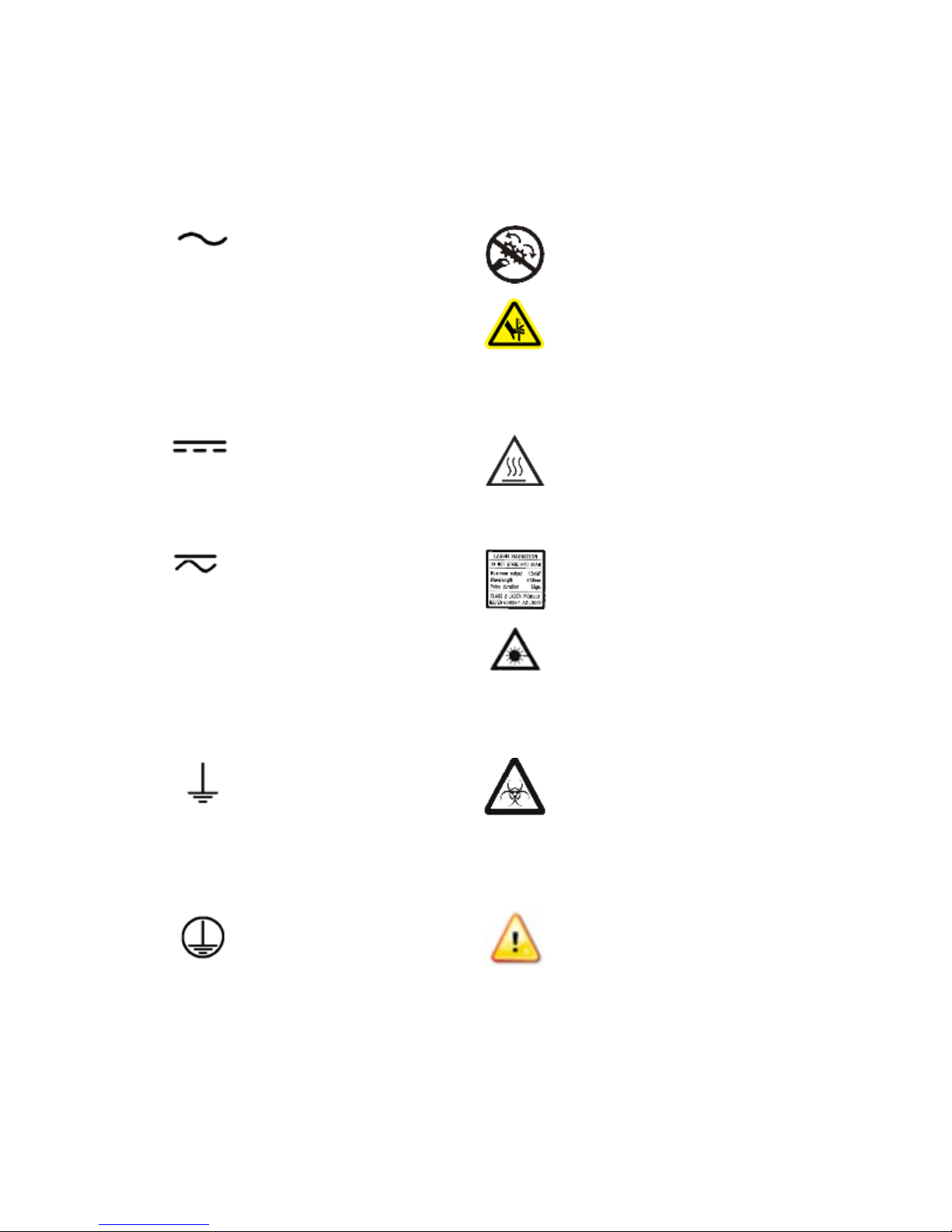
Safety Symbols
Some of the following symbols may appear on the instrument or accessories:
Alternating current
Courant alternatif
Wechselstrom
Corriente alterna
Corrente alternata
Warning, risk of crushing or
pinching
Attention, risque d'écrasement et
pincement
Warnen, Gefahr des Zerquetschens
und Klemmen
Precaución, riesgo del
machacamiento y sejeción
Attenzione, rischio di schiacciare ed
Direct current
Courant continu
Gleichstrom
Corriente continua
Corrente continua
Both direct and alternating
current
Courant continu et courant
alternatif
Gleich - und Wechselstrom
Corriente continua y
corriente alterna
alternata
Earth ground terminal
Borne de terre
Erde (Betriebserde)
Borne de tierra
Terra (di funzionamento)
Warning, hot surface
Attention, surface chaude
Vorsicht, heiße Oberfläche
Precaución, superficie caliente
Attenzione, superfice calda
Laser radiation: Do not stare into
beam
Rayonnement laser: Ne pas
regarder dans le faisceau
Laserstrahlung: nicht in den strahl
blicken
Radiación de laser: No mire
fijamente al rayo
Radiazione di laser: Non stare nel
Warning, potential biohazards
Attention, risques biologiques
potentiels
Warnung! Moegliche biologische
Giftsoffe
Atención, riesgos biológicos
Attenziones, rischio biologico
Protective conductor
terminal
Borne de terre de protection
Schultzleiteranschluss
Borne de tierra de
protección
Terra di protezione
Cytation 5
Caution (refer to accompanying
documents)
Attention (voir documents
d'accompanement)
Achtung siehe Begleitpapiere
Atención (vease los documentos
incluidos)
Attenzione, consultare la doc
annessa
xii | Preface
Chiuso
On (Supply)
Marche (alimentation)
Ein (Verbindung mit dem
Netz)
Conectado
Off (Supply)
Arrêt (alimentation)
Aus (Trennung vom Netz)
Desconectado
Aperto (sconnessione dalla
rete di alimentazione)
Consult instructions for use
Consulter la notice d'emploi
Gebrauchsanweisung beachten
Consultar las instrucciones de uso
Consultare le istruzioni per uso
In vitro diagnostic medical device
Dispositif médical de diagnostic in
vitro
Medizinisches In-Vitro
Diagnostikum
Dispositivo médico de diagnóstico
in vitro
Dispositivo medico diagnostico in
vitro
Warning, risk of electric
shock
Attention, risque de choc
électrique
Gefährliche elektrische
schlag
Precaución, riesgo de
sacudida eléctrica
Attenzione, rischio di scossa
elettrica
Separate collection for electrical
and electronic equipment
Les équipements électriques et
électroniques font l'objet d'une
collecte sélective
Getrennte Sammlung von Elektround Elektronikgeräten
Recogida selectiva de aparatos
eléctricos y electrónicos
Raccolta separata delle
apparecchiature elettriche ed
elettroniche
BioTek Instruments, Inc.

Installation

2 | Installation
Item
Part #
Cytation 5 Operator's Manual (delivered on USB flash
drive)
#2 Phillips screwdriver
01188
9/64" hex wrench
01623
Models with the imaging module:
FireWire cable
1220538
Microplate slide holder
1220548
Isolation table
1220521
Objective adapter collar wrench
1222187
Objective setup plate
1222531
3/32" hex wrench
48570
Models with an external dispense module (packed separately), with the following
accessories:
Injector
8040541
Inlet tubes (2) from supply bottles to syringe drives
7082121
250-µL syringes (2)
7083000
Package Contents
1321000
Power cord set (specific to installation environment):
Europe (Schuko)
USA/International
United Kingdom
Australia/New Zealand
USB cable 75108
FireWire desktop interface
OR
FireWire laptop card and power supply
75010
75011
75012
75013
01604
1220535
Power supply only:
01062
BioTek Instruments, Inc.
1: Unpack and Inspect the Reader | 3
Item
Part #
Syringe thumbscrews
19511
Priming plate
8042202
Injector tip priming trough
8042068
Dispense module communication cable
75107
Dispense module front cover
8042197
Dispense module box
8040534
Supply bottles (2, 30 mL)
7122609
Supply bottle holders (2)
8042193
Injector tip cleaning stylus and plastic storage bag
2872304
Strap reagent racks (6)
7212035
Models with the gas controller ("G" models)(packed separately):
Gas controller unit, CO2/O2 control
1210500
Shipping accessories, CO2/O2 control
1210010
Gas Controller Unit, CO2 only
1210504
Shipping accessories, CO2 only
1210009
1: Unpack and Inspect the Reader
The Cytation 5 should be removed from the box by two people. The instrument
with all available modules weighs up to 80 pounds (36.6 kg).
Save all packaging materials. If you need to ship the reader to BioTek for repair
or replacement, you must use the original materials. Using other forms of
commercially available packaging, or failing to follow the repackaging
instructions, may void your warranty.
During the unpacking process, inspect the packaging, reader, and accessories
for shipping damage. If the reader is damaged, notify the carrier and your
BioTek representative. Keep the shipping boxes and the packaging materials
for the carrier's inspection. BioTek will arrange for repair or replacement
immediately.
1. Open the shipping box, remove the instrument from the box, and place it on
a level, stable surface.
2. Place the packaging materials back into the shipping box for reuse if the
instrument needs to be shipped again.
3. For the instruments with the imaging module: Open the accessories box, and
remove the isolation table.
Cytation 5

4 | Installation
2: Unpack and Inspect the Dispenser
If applicable:
1. Open the shipping box. Remove the accessories box and foam insert that
contains the injector tubing and bottle holders.
2. Lift out the dispenser and place it on a level surface.
3. Open the accessories box and remove its contents.
4. Place all packaging materials into the shipping box for reuse if the dispenser
needs to be shipped.
3: Unpack and Inspect the Gas Controller
If applicable:
1. Open the shipping box. Remove the accessories, and set them aside.
2. Lift out the gas controller, and place it on a level surface.
3. Place all packaging materials into the shipping box for reuse if the gas
controller needs to be shipped.
4: Select an Appropriate Location
Install the reader on a level, stable surface in an area where ambient temperatures
between 18°C (64°F) and 30°C (86°F) can be maintained.
Leave at least six inches of space between the instrument’s rear panel and any other
object. This space ensures proper air flow in and out of the instrument.
The reader is sensitive to extreme environmental conditions. Avoid the following:
• Excessive humidity. Condensation directly on the sensitive electronic circuits
can cause the instrument to fail internal self-checks. The humidity must be in
the range of 10–85%, non-condensing.
• Excessive ambient light. Bright light may affect the reader’s optics and
readings, reducing its linear range.
• Dust. Readings may be affected by extraneous particles (such as dust) in the
microplate wells. A clean work area is necessary to ensure accurate readings.
• Vibration. The instrument should be installed in a vibration-free environment.
Be sure to position the instrument away from other devices that could
potentially create vibration during the read process.
If you are installing a BioStack for operation with the Cytation 5, you may
wish to seat the instruments in their alignment plates now. Refer to the
stacker's operator's manual for more information.
BioTek Instruments, Inc.
4: Select an Appropriate Location | 5
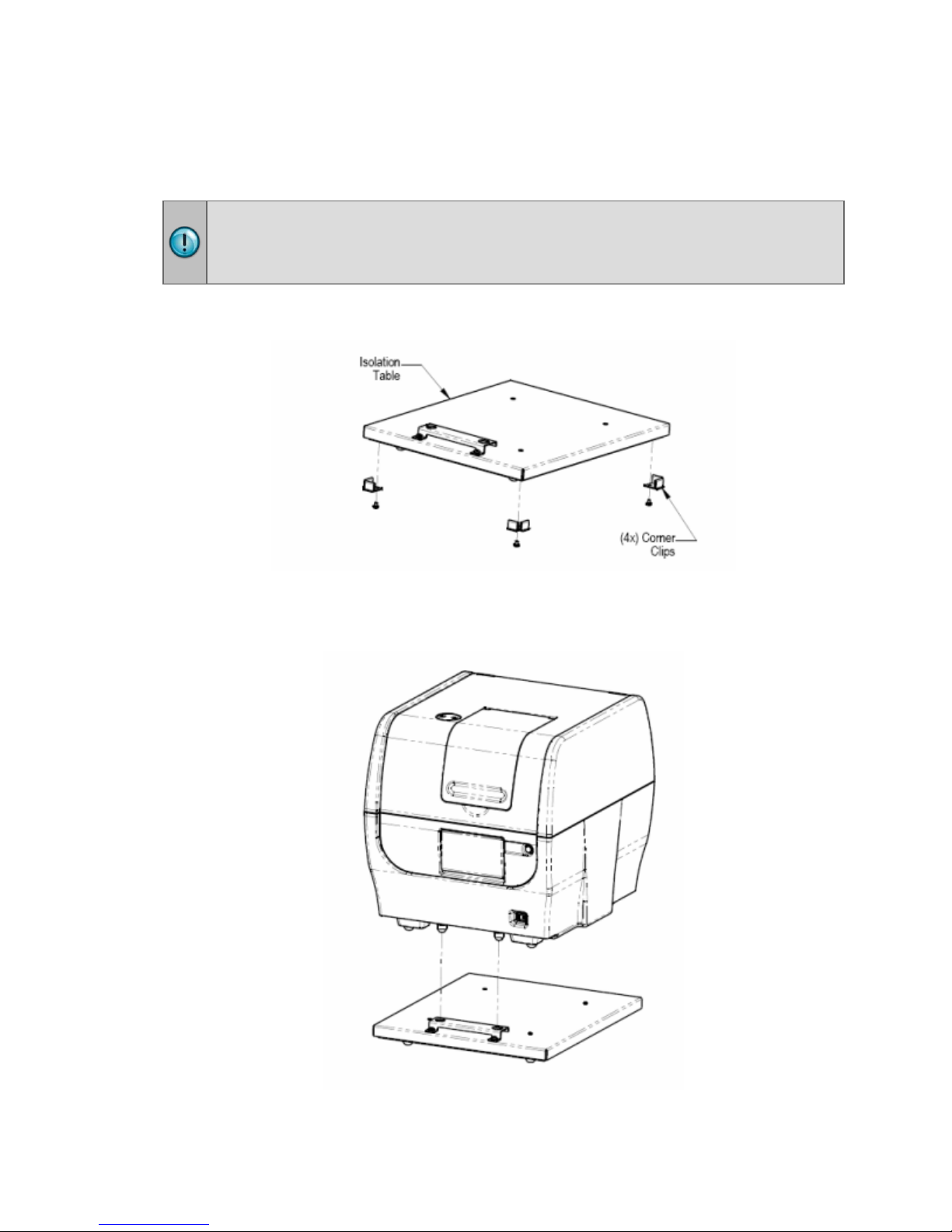
Installing Instruments with the Isolation Table
Cytation 5 models with the imaging module can be used with an isolation table,
which helps to eliminate vibration during image reads.
Do not use the isolation table when operating the Cytation 5 with a microplate
stacker. Store the isolation table in a clean, dry location.
1. Remove the four corner clips from the isolation table.
2. Place the isolation table in the selected installation location.
3. Place the instrument on the table as shown next:
Cytation 5
6 | Installation
The isolation table contains material that dampens vibration. Over time, this material
becomes compressed and can lose effectiveness. The isolation table has a color
indicator that turns from green to red to show when the table should be replaced
because the dampening material has been compressed.
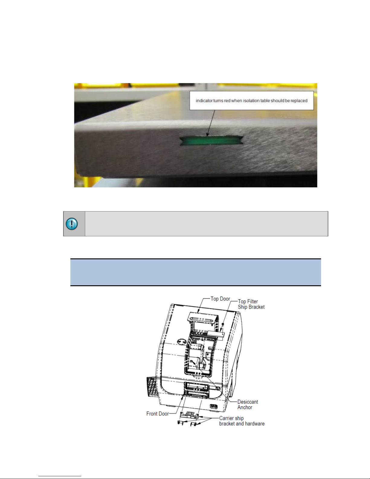
5: Remove the Shipping Hardware
Remove all shipping hardware before you turn on the reader.
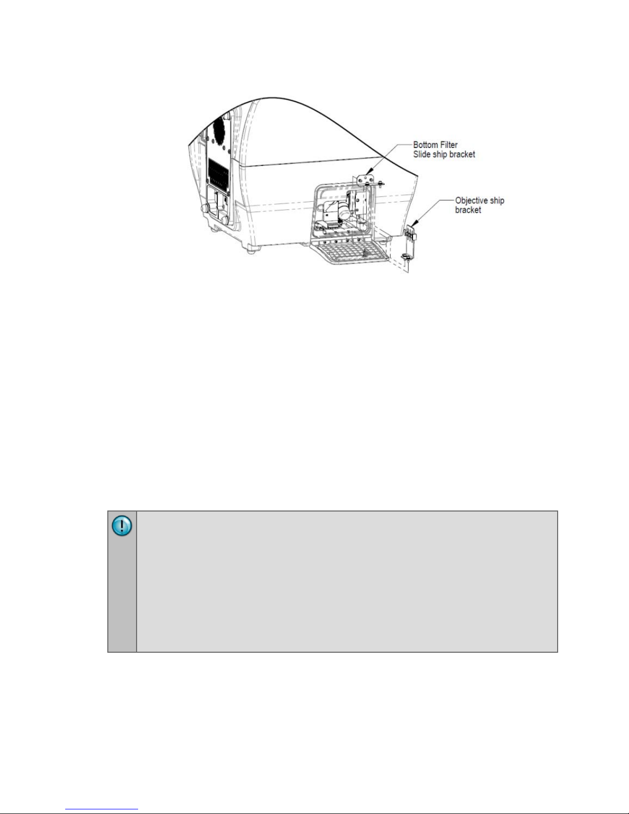
1. Locate the shipping hardware.
The figures below depict a Cytation 5 with the filter module and imaging
module.
BioTek Instruments, Inc.
6: Install the Power Supply | 7
2. Open the top door, and remove the reusable zip tie and desiccant packet
from the desiccant anchor.
3. If equipped, use the supplied screwdriver to remove the top filter shipping
bracket.
4. Open the front door, and using the supplied screwdriver, remove the carrier
shipping bracket.
5. If equipped with the imaging module, use a 9/64" hex wrench to remove the
bottom filter slide ship bracket
6. Push the filter slide back, and remove the two-piece objective ship bracket.
7. Store the shipping hardware in a safe location, in case the instrument needs
to be shipped again.
6: Install the Power Supply
Power Rating. The instrument must be connected to a power receptacle that
provides voltage and current within the specified rating for the system. Use of
an incompatible power receptacle may produce electrical shock and fire
hazards.
Electrical Grounding. Never use a plug adapter to connect primary power to
the instrument. Use of an adapter disconnects the utility ground, creating a
severe shock hazard. Always connect the system power cord directly to an
appropriate receptacle with a functional ground.
1. Locate the power inlet on the back of the reader.
2. Examine the power supply's plug. It has a small groove that lines up with a
Cytation 5
tab inside the power inlet.
3. Insert the plug into the power inlet and plug the power supply's cord into an
appropriate power receptacle.
8 | Installation
Do not plug the power supply into a power receptacle until after the
power supply is connected to the instrument.
7: Install the Gas Controller (if applicable)
The gas controller is an external module that enables the user to control CO2 and O2
concentrations inside the attached instrument’s reading chamber. If you purchased
the module for operation with the Cytation 5, refer to the Gas Controller User Guide
for installation instructions.
8: Unpack and Install the Joystick (if
applicable)
If applicable:
1. Open the shipping box, lift out the joystick, and place it on a level surface.
2. Place all packaging materials into the shipping box for reuse if the joystick
needs to be shipped.
3. Locate the joystick cable. Plug one end into the port on the back of the
joystick. Plug the other end into the joystick port on the rear of the reader.
9: Install the Dispenser
Place the dispense module on top of the reader or on top of the gas
controller (if equipped). Do not place the dispenser next to the reader.
BioTek Instruments, Inc.

9: Install the Dispenser | 9
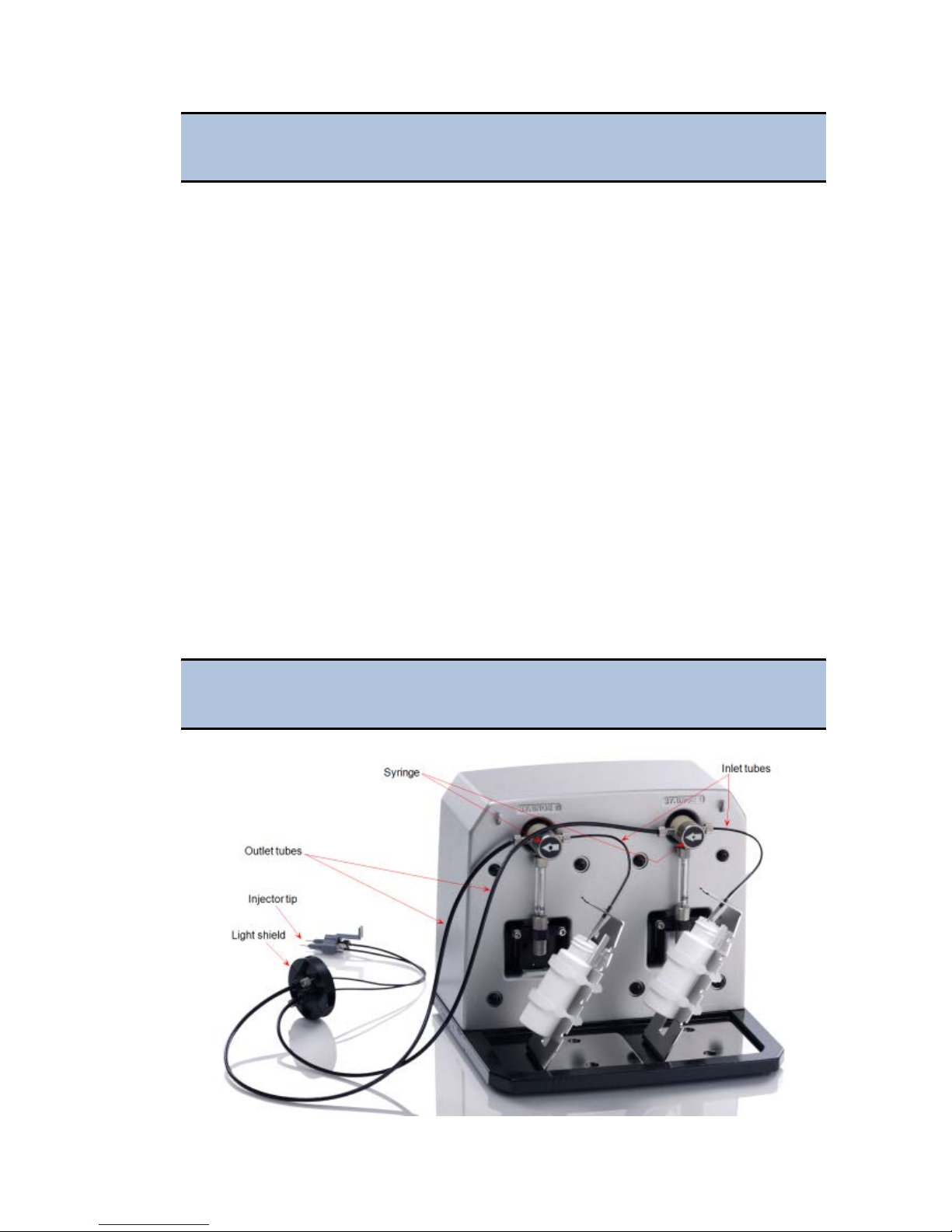
1. Open the plastic bag containing the injector tube and tips. Remove the clear
plastic shrouds from the tubes.
2. Remove the two inlet tubes from their plastic canisters.
3. Identify the two syringe valves on the dispense module. Each is labeled with
a left-pointing arrow.
When installing the inlet and outlet tubes, do not use any tools. Fingertighten only!
4. Screw the fitting of one inlet tube into the right side of the Syringe 1 valve.
5. Identify the #1 outlet tube, and screw it into the left side of the Syringe 1
valve.
6. Repeat these steps to attach the inlet and outlet tubing for Syringe 2.
It is critical that the tubing is installed in the correct ports. Otherwise,
injected fluid may miss the intended well.
7. Remove the round tubing feed-through cover from the top of the reader (2
screws). Store the cover and screws with the shipping hardware in case the
reader needs to be shipped again.
8. Thread the injector tip holder, with outlet tubing connected to both ports,
through the hole in the top of the reader.
9. Open the reader's top door, and, holding the injector tip holder by the tab,
insert the injector tips into the appropriate holes inside the reader.
A magnet located between the injector tips helps to guide the tips into
place and secures them in the reader.
10. Place the tubing feed-through cover over the hole in the top of the reader and
finger-tighten the thumbscrews to secure it.
11. Remove the two syringes from their protective boxes. They are identical and
interchangeable.
12. Install both syringes.
• Hold the syringe vertically with the threaded end at the top.
• Screw the top of the syringe into the bottom of the syringe valve. Finger-
tighten only.
• Carefully pull down the bottom of the syringe until it rests inside the hole
in the bracket.
• Pass a thumbscrew up through this hole and thread it into the bottom of
the syringe. Hold the syringe to prevent it from rotating while tightening
the thumbscrew. Finger-tighten only.
Cytation 5
10 | Installation
The Cytation 5 is controlled by Gen5 software running on a host computer.
provided in Gen5 Getting Started Guide to install the software.
13. Locate the dispenser cable. Plug one end into the port on the left side of the
dispenser. Plug the other end into the “Dispenser Port” on the rear of the
reader.
14. Locate the injector tip-cleaning stylus, packaged in a small cylinder. Attach
the cylinder to the back of the dispenser for storage.
10: Connect the Host Computer
The Cytation 5 is equipped with a USB port for connection to the host computer.
Connect the supplied USB cable between the USB port on the back of the reader and
an available USB port on the computer.
11: Install Gen5
There is a certain sequence of events that must be followed to ensure that the
software is properly installed and configured. Please follow the instructions
12: Turn on the Reader
If you have not already done so, turn on the reader. The reader’s power switch is
located on the lower-right corner of the front panel. The reader performs a system
test. When the test is completed, the reader extends the microplate carrier.
The carrier eject button, located above to the reader’s power switch, can
be used to extend/retract the microplate carrier.
13: Establish Communications
Before performing this step, refer to the instructions that shipped with
the USB Driver Software on the Gen5 software media to install the
necessary drivers.
1. If not already done, start Gen5 and log in if prompted. The default System
Administrator password is admin.
2. From the Gen5 main screen, select
and click
3. Set the Reader Type to
4. Select
Add Reader.
Cytation 5, and click OK to continue.
Plug & Play.
System > Instrument Configuration
BioTek Instruments, Inc.

14: Install the Imager Module | 11
A Cytation 5 must be connected via USB to the computer and turned
on to appear in the Available Plug & Play Readers list.
5. To test that Gen5 can communicate with the instrument, click Test
Communications
displays a success message. Return to Gen5’s main screen.
. If the communication attempt is successful, Gen5
Communication Errors
If the communication attempt is not successful, try the following:
• Is the reader connected to the power supply and turned on?
• Is the communication cable firmly attached to both the reader and the
computer?
• Did you select the correct Reader Type in Gen5?
• Did you install the USB driver software?
If you remain unable to get Gen5 and the reader to communicate with
each other, contact BioTek’s Technical Assistance Center.
14: Install the Imager Module
Several steps are required to install the imager module.
1. Install the FireWire card and driver
2. Set up Gen5 for imaging
3. Install the objectives, LED cubes, and imaging filter cubes, and run Auto
Calibration
Tools:
• Screwdriver: Desktop computer users typically need a screwdriver to install the
FireWire card.
• 3/32" hex (or Allen) wrench
1. FireWire Video Card: Computer and Camera Setup
BioTek supplies the required FireWire card (PCI Express Card-IEEE-1394b) for either
a desktop computer or a laptop. Follow the applicable instructions for your
workplace, then install the FireWire software driver on your computer.
Cytation 5
12 | Installation
Desktop Computer: Install the FireWire Card
To avoid electrostatic discharge and damage to internal components,
ground yourself by using wrist grounding straps or by touching a metal
surface on the computer's chassis.
The following directions provide general steps for installing a PCI Express
card. Talk to your company's IT representative for assistance with these
steps. For more detailed help, contact BioTek TAC.
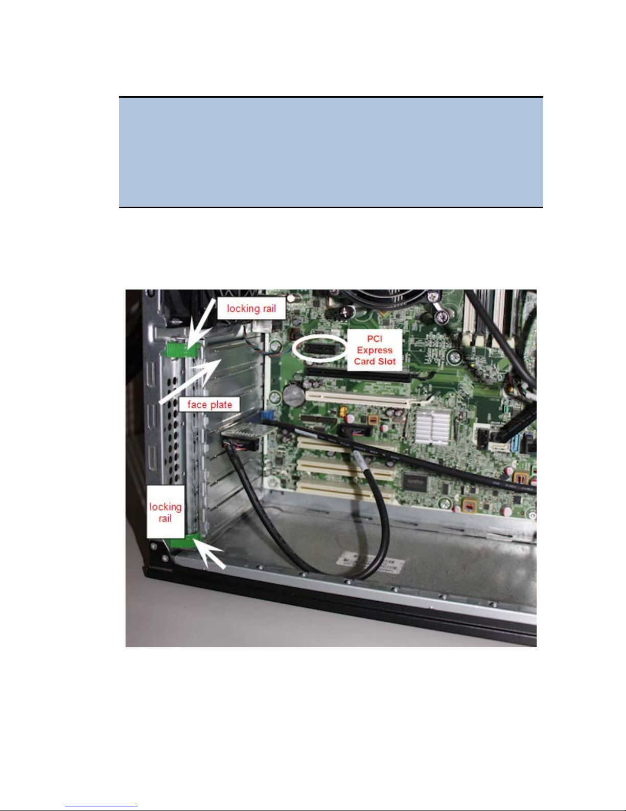
1. Turn off your computer, then remove the outside case. Depending on the
computer, remove either one side of the tower or the entire cover.
2. Locate the PCI Express slot. Open the card retainer, and remove any existing
graphics card (if necessary) or blank port located in the PCI Express slot.
3. Insert the PCI Express card, aligning it with its slot.
4. Press the card firmly into place, and secure the card with a locking rail or
screws.
5. Replace your computer's outside case, then power on the computer.
BioTek Instruments, Inc.
14: Install the Imager Module | 13
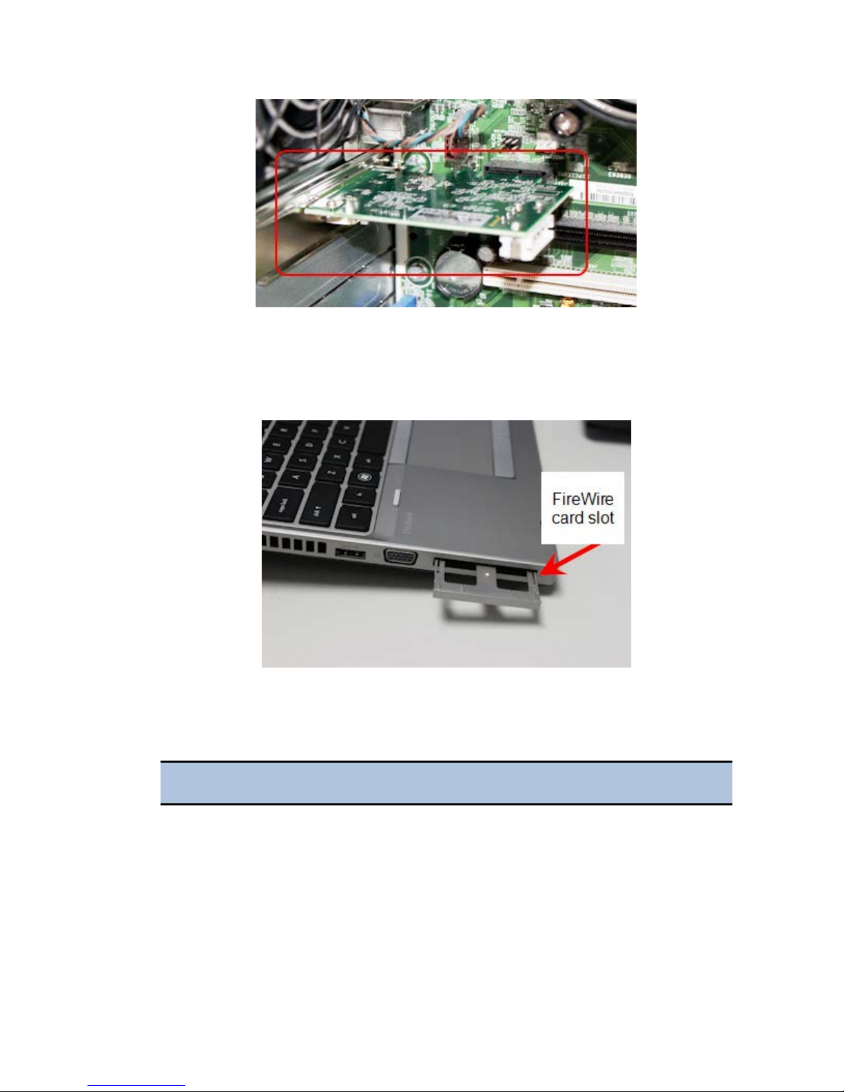
Laptop Computer: Install the FireWire Card
1. Remove the PCI Express port cover or any existing PCI Express card from
your laptop.
2. Touch a metal object to discharge any static electricity.
3. Remove the PCI Express card from the packaging.
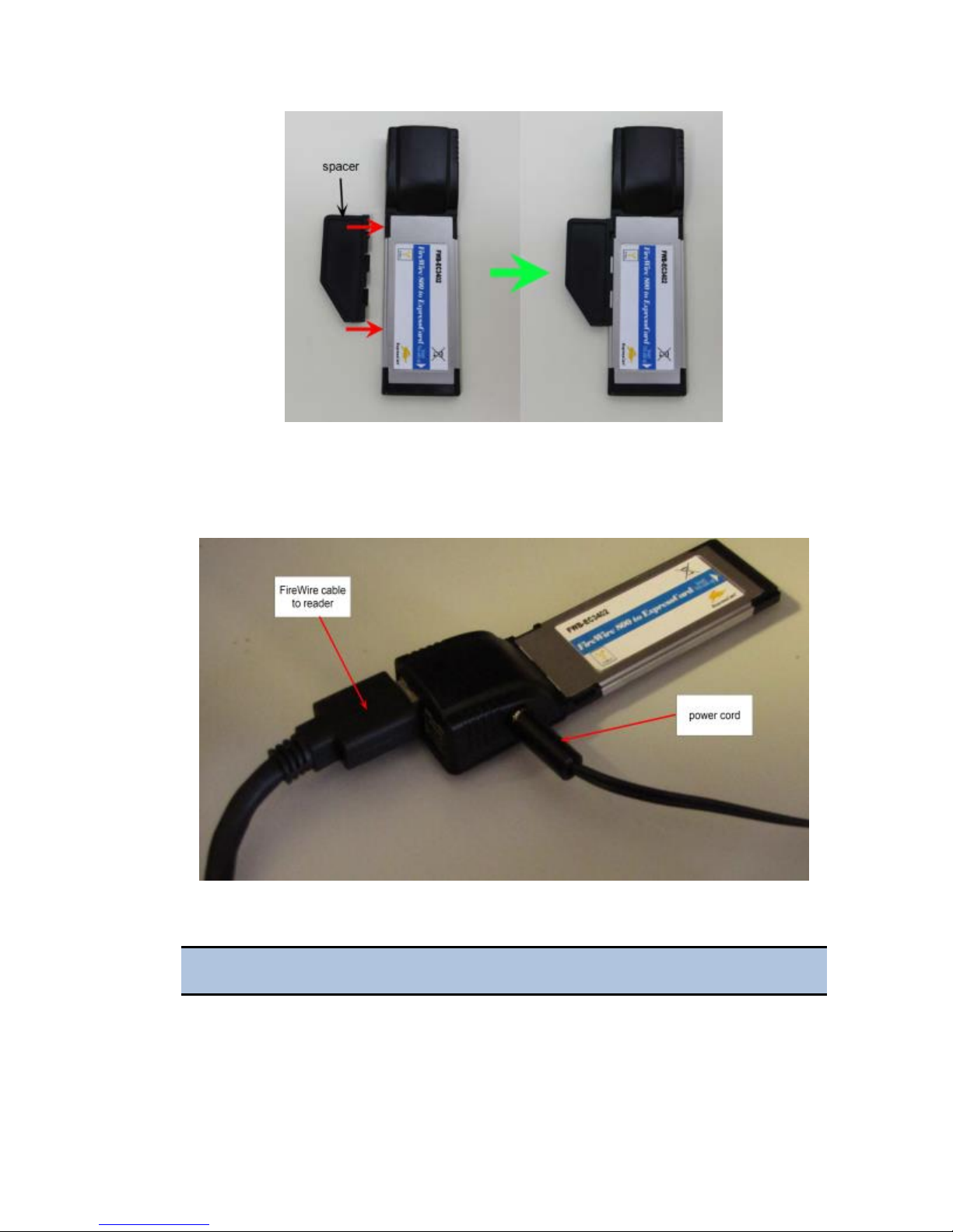
4. Attach the spacer, if required, to the FireWire PCI Express card.
The spacer does not fit tightly. Ensure that it does not fall off.
Cytation 5
14 | Installation
5. Insert the FireWire Express card, with the label facing up, into the
appropriate slot on your laptop.
6. Plug the power cord into the card, then plug the cord into a power outlet.
Install the FireWire Driver
You must install the PCI Express card before performing this step.
1. Navigate to the Gen5 program files on your computer, for example,
C:\Program Files\BioTek\Gen5 2.07.
BioTek Instruments, Inc.
14: Install the Imager Module | 15
2. Open the Firewire Drivers folder, and then open the folder appropriate for
your computer: Windows_32 (for Windows 32-bit) or Windows_64 (for
Windows 64-bit).
3. In Windows 7 and higher, right-click
as Administrator
to run the driver installer. When the installer is finished,
InstallPGRDriver.bat and select Run
a message appears: "SUCCESS: Installed package <path to package>". If you
do not see this message, contact BioTek TAC.
4. After installing the FireWire driver, restart your computer.
5. When the reboot process is complete, insert one end of the FireWire cable
into the back of the reader, and insert the other end into the new port (in the
card you installed) on your computer.
Establish Communication with the Camera
1. From the Gen5 main screen, select System > Instrument Configuration,
select
Cytation 5, and then click View/Modify.
2. Click
Camera Information. If communication is successful, Gen5 displays
information about the camera.
Troubleshooting Communication with the Camera
• Have you established communication with the instrument first?
• Did you install the FireWire software driver?
• Is the FireWire cable installed? Is your laptop card plugged into an electrical
outlet?
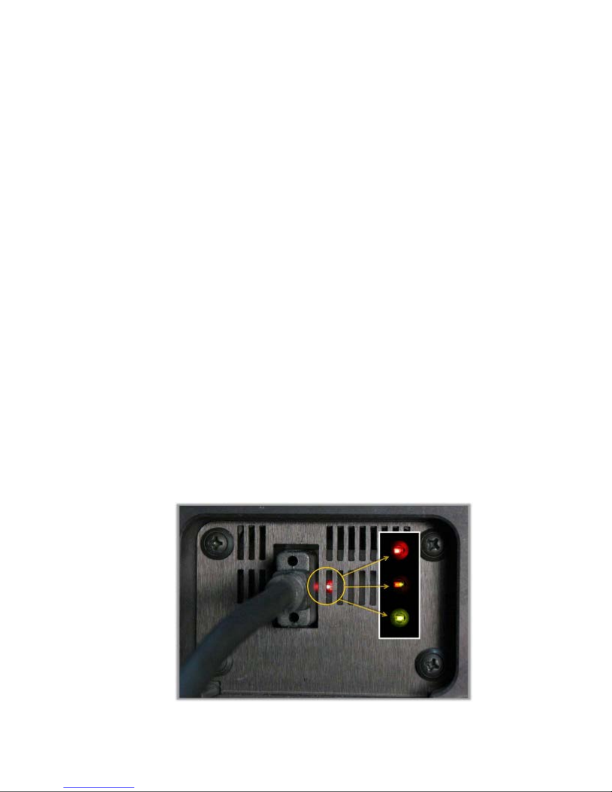
• Is the LED light on the back of the reader lit up?
• Red: Power to the camera from the FireWire card
• Half-Red/Half-Green: Ready state
• Green: Communicating/activity
Cytation 5

16 | Installation
2. Set Up Gen5 for Imaging
Configuration information must be set before any optical components are installed.
Use Gen5 to update the instrument's onboard settings. The LED cubes and imaging
filter cubes must be installed with the reader off. Follow these installation steps in
the order in which they are given.
1. In Gen5, select
View/Modify > Setup
System > Instrument Configuration > Cytation 5 >
.
2. On the Imaging Configuration tab, input the objective and LED cube and
imaging filter cube configurations (see 3a. Setting the Objective, LED Cube,
and Imaging Filter Cube Configuration on page 17), then click
Values
.
Send
Click Access next to an objective position in the Objective
Configuration area to lower the focusing system into the desired
access position and to rotate the objective turret to the selected
objective's installation position.
3. Install the objectives (see 3b. Install the Objectives on page 17) in their
defined locations.
4. Power off the instrument, and install the LED cubes and imaging filter cubes
(see 3c. Install the LED Cubes and Imaging Filter Cubes on page 17) in their
defined locations. Close the side access door.
Leave Gen5 open with the Reader Setup dialog onscreen while
performing the next steps.
5. Power on the instrument. After the self-test, the instrument will beep and the
eject button LED will be red, indicating that the objectives must be
calibrated.
6. Press the carrier eject button to stop the beeping.
7. Click
Auto Calibration. Note that this process can take up to 15 minutes on
an instrument with six objective installed.
Phase contrast components are calibrated in the factory before shipment.
You do not need to run the Phase Ring Configuration and Calibration
routines at this time.
BioTek Instruments, Inc.

14: Install the Imager Module | 17
3a. Setting the Objective, LED Cube, and Imaging Filter Cube
Configuration
When you install an LED cube, an imaging filter cube, or an objective, you must set
the cubes' and objectives' configuration before physically changing or installing
them.
If you physically install an LED cube, an imaging filter cube, or an
objective before setting the new configuration, the instrument may fail its
self-test.
1. From the main Gen5 screen, click System > Instrument Configuration.
2. Select the
Imaging Configuration tab.
3. In the Objective Configuration area, select the objective for the position or
positions you want to define, or select
objective from the instrument. Click
4. In the LED and Imaging Filter Cube Configuration area, select the filter cube
for the position you want to define, or select
filter cube from the instrument. The corresponding LED cube part number is
filled in automatically.
5. Click
6. For LED cube and imaging filter cube changes, follow the on-screen
procedure.
Cytation 5, click View/Modify > Setup, and select the
None if you are removing an
Access.
None if you are removing the
Send Values.
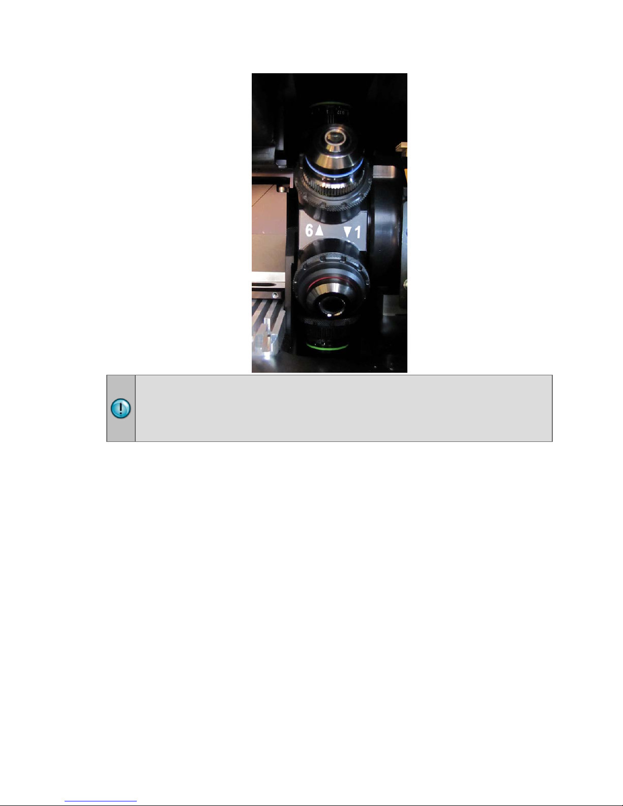
3b. Install the Objectives
Before installing a 20X, 40X, or 60X objective, either phase or standard,
set its correction collar to match your plate type. See the Cytation 5
Operator’s Manual for more information and instructions.
After defining the objectives and their locations in Gen5:
1. Turn the knob on the side access door to release the latch, and open the door.
Cytation 5
18 | Installation
If you are installing an objective with a correction collar (i.e., a 20X, 40X, or
60X objective), be sure to grasp the objective by the adapter, not by the
correction collar, to avoid changing the correction collar settings.
2. Screw each objective into its defined position. Do not overtighten the
objectives.
3c. Install the LED Cubes and Imaging Filter Cubes
1. With the instrument powered off, slide the filter slide out of the instrument.
2. Place the new LED cube in the appropriate position (Position 1, 2, 3, or 4) on
the filter slide.
3. Use the 3/32" hex wrench to screw the LED cube onto the filter slide.
4. Place the imaging filter cube on top of the LED cube you installed, and use
the hex wrench to screw it to the LED cube.
5. Insert the LED cube’s wire clip into the socket on the carrier.
BioTek Instruments, Inc.
 Loading...