

Page 1
Isolera
User Manual
Page 2

Safety and Document Conventions
The Isolera system should only be operated and maintained by trained individuals. Please read this manual
carefully before working with the system. To guarantee safe and effective operation it is absolutely necessary to
follow all of the instructions in this user manual. All information is believed to be complete and accurate at the
time of publication, but is subject to change.
Pay close attention to text with a NOTE or WARNING heading. A NOTE gives information that is crucial to the
operation being described. A WARNING indicates important information that will prevent harm to personnel
and/or damage to the system.
NOTE
Note text appears in the manual to provide additional or crucial information about
the current topic. It may indicate a situation in which the system may not perform
as expected unless specific guidelines are followed.
WARNING
The Warning note indicates a hazard that could result in serious injury to the user
and/or damage to the equipment unless good laboratory practices (GLP) and/or
manufacturer's guidelines are followed.
Warranty and Liability
See the “Biotage Terms & Conditions of Sale” document at www.biotage.com.
Trademark Acknowledgement
The following trademarks are owned by Biotage® AB: Biotage, Biotage ZIP, Advancer, Advancer Kilobatch,
Advancer 350, AFFINILUTE, Endeavor, EVOLUTE, ExploraSep, Firefly design ( ), FLASH+, FlashMaster,
FlashVac, Horizion, HPFC, HP-SIL, HP-Sphere, Initiator, Initiator+, Isolera, Isolera Four, Isolera LS, Isolera One,
Isolera Prime, Isolera Spektra, Isolera Spektra Four, Isolera Spektra LS, Isolera Spektra One, ISOLUTE, IST,
IST design ( ), KILOPREP, KP-C18-HS, KP-C18-WP, KP-C4-WP, KP-NH, KP-Sil, MIP4SPE, MIP Rule of 6,
MIP[4]Process, MIP[4]Proteins, PathFinder, PRESSURE+ 48, PRESSURE+ 96, RapidTrace, RapidTrace +,
Resolux, Samplet, SIM, SNAP, SNAP Ultra, SP1, SP4, SPE Dry 96, SPE Dry 96 Dual, SP Wave, Syro Wave,
TurboVap, VacMaster, V-10, ZIF, ZIF-SIM, ZIP-Sphere, and 1-Point Support.
Other product and company names mentioned herein may be trademarks or registered trademarks and/or
service marks of their respective owners, and are used only for explanation and to the owners' benefit, without
intent to infringe.
Copyright
Biotage Sweden AB reserves the right to make changes to the information contained herein without prior notice.
No part of this manual may be reproduced or transmitted in any form or by any means, electronic or
mechanical, for any purpose, without the expressed written permission of Biotage Sweden AB.
© Copyright 2007–2012 Biotage Sweden AB. All rights reserved.
User Documentation List
The following documents are provided on the “Isolera User Documentation” CD (P/N 411831):
• “Isolera Installation and Safety”, P/N 411828
• “Isolera User Manual” (this publication), P/N 411829
• “Quick Guide for Isolera”, P/N 411830
• “Isolera Safety Translations”, P/N 412861
Page ii
Page 3

Table of Contents
1: Description and Specifications - - - - - - - - - - - - - - - - - - - - - - - - - - - - - - - - - - - 1-1
General System Description - - - - - - - - - - - - - - - - - - - - - - - - - - 1-1
Basic System Components - - - - - - - - - - - - - - - - - - - - - - - - - 1-2
System Configurations - - - - - - - - - - - - - - - - - - - - - - - - - - - 1-2
Programmed Functions - - - - - - - - - - - - - - - - - - - - - - - - - - - 1-3
User Documentation - - - - - - - - - - - - - - - - - - - - - - - - - - - - 1-3
Accessories - - - - - - - - - - - - - - - - - - - - - - - - - - - - - - - - 1-3
Software Description - - - - - - - - - - - - - - - - - - - - - - - - - - - - - - 1-7
Main Menu - - - - - - - - - - - - - - - - - - - - - - - - - - - - - - - - 1-7
Data Administration Mode - - - - - - - - - - - - - - - - - - - - - - - - - 1-7
System Mode - - - - - - - - - - - - - - - - - - - - - - - - - - - - - - - 1-8
Chemistry Mode - - - - - - - - - - - - - - - - - - - - - - - - - - - - - - 1-9
Method Tab (Chemistry Mode)- - - - - - - - - - - - - - - - - - - - - - - - 1-11
Status Tab (Chemistry Mode) - - - - - - - - - - - - - - - - - - - - - - - - 1-11
Results Tab (Chemistry Mode)- - - - - - - - - - - - - - - - - - - - - - - - 1-14
Solvents Tab (Chemistry Mode) - - - - - - - - - - - - - - - - - - - - - - - 1-15
Isolera Remote Viewer - - - - - - - - - - - - - - - - - - - - - - - - - - - 1-16
Specifications - - - - - - - - - - - - - - - - - - - - - - - - - - - - - - - - - 1-17
General System Specifications- - - - - - - - - - - - - - - - - - - - - - - - 1-17
Operational Performance Specifications - - - - - - - - - - - - - - - - - - - - 1-18
Solvent Specifications - - - - - - - - - - - - - - - - - - - - - - - - - - - 1-19
Chemical Resistance of the Peristaltic Pump Tube (Isolera LS) - - - - - - - - - - 1-20
2: Data Administration - - - - - - - - - - - - - - - - - - - - - - - - - - - - - - - - - - - - - - - - - - 2-1
Log into the Data Administration Mode - - - - - - - - - - - - - - - - - - - - - - 2-1
Administrate the Cartridge List - - - - - - - - - - - - - - - - - - - - - - - - - 2-2
Add a Cartridge Type - - - - - - - - - - - - - - - - - - - - - - - - - - - 2-2
Delete an Unused Cartridge Type - - - - - - - - - - - - - - - - - - - - - - 2-2
Edit a Cartridge Type- - - - - - - - - - - - - - - - - - - - - - - - - - - - 2-3
Select Cartridge Types to List - - - - - - - - - - - - - - - - - - - - - - - - 2-3
Administrate the Method List - - - - - - - - - - - - - - - - - - - - - - - - - - 2-3
Delete Methods - - - - - - - - - - - - - - - - - - - - - - - - - - - - - - 2-3
Export Methods - - - - - - - - - - - - - - - - - - - - - - - - - - - - - - 2-4
Import Methods - - - - - - - - - - - - - - - - - - - - - - - - - - - - - - 2-4
Set Default Methods - - - - - - - - - - - - - - - - - - - - - - - - - - - - 2-4
Administrate the Rack List - - - - - - - - - - - - - - - - - - - - - - - - - - - 2-5
Add a Rack Type - - - - - - - - - - - - - - - - - - - - - - - - - - - - - 2-5
Delete an Unused Rack Type - - - - - - - - - - - - - - - - - - - - - - - - 2-6
Edit a Rack Type - - - - - - - - - - - - - - - - - - - - - - - - - - - - - 2-6
Select Rack Types to List - - - - - - - - - - - - - - - - - - - - - - - - - - 2-6
Administrate the Result List - - - - - - - - - - - - - - - - - - - - - - - - - - - 2-6
Export and Delete Result Records - - - - - - - - - - - - - - - - - - - - - - 2-7
Clean Up the System’s Database- - - - - - - - - - - - - - - - - - - - - - - 2-7
Page iii
Page 4

Administrate the Solvent List - - - - - - - - - - - - - - - - - - - - - - - - - - 2-8
Add a Solvent - - - - - - - - - - - - - - - - - - - - - - - - - - - - - - - 2-8
Delete an Unused Solvent - - - - - - - - - - - - - - - - - - - - - - - - - 2-8
Edit a Solvent - - - - - - - - - - - - - - - - - - - - - - - - - - - - - - - 2-9
Select Solvents to List - - - - - - - - - - - - - - - - - - - - - - - - - - - 2-9
Administrate the User List - - - - - - - - - - - - - - - - - - - - - - - - - - - 2-9
Add a User Account - - - - - - - - - - - - - - - - - - - - - - - - - - - - 2-9
Change the Password or Privilege - - - - - - - - - - - - - - - - - - - - - - 2-10
Delete a User Account - - - - - - - - - - - - - - - - - - - - - - - - - - - 2-10
Reset the Number of Performed Runs - - - - - - - - - - - - - - - - - - - - 2-10
3: System Settings - - - - - - - - - - - - - - - - - - - - - - - - - - - - - - - - - - - - - - - - - - - - 3-1
Log into the System Mode - - - - - - - - - - - - - - - - - - - - - - - - - - - 3-1
Change Detector Settings - - - - - - - - - - - - - - - - - - - - - - - - - - - - 3-2
Enable or Disable the Internal Detector - - - - - - - - - - - - - - - - - - - - 3-2
Connect and Enable an External Detector - - - - - - - - - - - - - - - - - - - 3-2
Disable an External Detector - - - - - - - - - - - - - - - - - - - - - - - - 3-3
Enable or Disable the Leak Detector - - - - - - - - - - - - - - - - - - - - - 3-3
Change General Settings - - - - - - - - - - - - - - - - - - - - - - - - - - - - 3-4
Set the Date and Time - - - - - - - - - - - - - - - - - - - - - - - - - - - 3-4
Enable or Disable Mouse Pointer - - - - - - - - - - - - - - - - - - - - - - - 3-4
Set the Pressure Unit - - - - - - - - - - - - - - - - - - - - - - - - - - - 3-4
Set the Language Used in the Chemistry Mode- - - - - - - - - - - - - - - - - 3-4
Enable the λ-All Detection Mode and TLC to Step Gradient Editor - - - - - - - - - 3-5
Configure a Network Connection - - - - - - - - - - - - - - - - - - - - - - - - - 3-5
Change Report Settings - - - - - - - - - - - - - - - - - - - - - - - - - - - - 3-6
Set Up a Printer and Auto Print of Reports - - - - - - - - - - - - - - - - - - 3-6
Set Up File Sharing and Auto Save of Reports - - - - - - - - - - - - - - - - - 3-7
Set Up Auto Send of Reports - - - - - - - - - - - - - - - - - - - - - - - - 3-8
Change Runtime Settings - - - - - - - - - - - - - - - - - - - - - - - - - - - - 3-8
Enable or Disable Audible Alarm - - - - - - - - - - - - - - - - - - - - - - - 3-8
Enable or Disable Automatic Rack Allocation- - - - - - - - - - - - - - - - - - 3-8
Enable or Disable Peak Mode - - - - - - - - - - - - - - - - - - - - - - - - 3-9
Enable or Disable Auto Extend- - - - - - - - - - - - - - - - - - - - - - - - 3-9
Enable or Disable Monitoring of Reservoirs - - - - - - - - - - - - - - - - - - 3-9
Enable or Disable Run Requirement Estimation - - - - - - - - - - - - - - - - 3-10
Specify How Flushes Are Performed - - - - - - - - - - - - - - - - - - - - - 3-10
Configure Collection and Fractionation - - - - - - - - - - - - - - - - - - - - 3-11
Maintenance - - - - - - - - - - - - - - - - - - - - - - - - - - - - - - - - - 3-11
Export the System Configuration and Logs - - - - - - - - - - - - - - - - - - 3-11
Restore the System Configuration - - - - - - - - - - - - - - - - - - - - - - 3-11
Back Up and Restore the System’s Database - - - - - - - - - - - - - - - - - 3-12
Calibrate the Touch Screen - - - - - - - - - - - - - - - - - - - - - - - - - 3-12
Calibrate the Fraction Collector - - - - - - - - - - - - - - - - - - - - - - - 3-13
Calibrate the Internal Detector - - - - - - - - - - - - - - - - - - - - - - - 3-13
Perform an Intensity Scan of the Internal Detector - - - - - - - - - - - - - - - 3-13
Clean the Collect Valve - - - - - - - - - - - - - - - - - - - - - - - - - - - 3-13
Release Stuck Check Valves- - - - - - - - - - - - - - - - - - - - - - - - - 3-14
View and Reset the Usage Statistics - - - - - - - - - - - - - - - - - - - - - 3-14
Page iv
Page 5

4: Operation - - - - - - - - - - - - - - - - - - - - - - - - - - - - - - - - - - - - - - - - - - - - - - - - - 4-1
Start Up the System - - - - - - - - - - - - - - - - - - - - - - - - - - - - - - 4-1
Shut Down the System - - - - - - - - - - - - - - - - - - - - - - - - - - - - - 4-1
Control the UV Lamp - - - - - - - - - - - - - - - - - - - - - - - - - - - - - - 4-2
Create, Open, and Edit Methods - - - - - - - - - - - - - - - - - - - - - - - - - 4-2
Create or Open a Method - - - - - - - - - - - - - - - - - - - - - - - - - - 4-2
Calculate Gradient from TLC Data - - - - - - - - - - - - - - - - - - - - - - 4-10
Create a Method Using the Method Wizard - - - - - - - - - - - - - - - - - - 4-13
Gradient Optimization - - - - - - - - - - - - - - - - - - - - - - - - - - - 4-13
Create a Method Using a Web Browser - - - - - - - - - - - - - - - - - - - - 4-14
Prepare and Run a Purification- - - - - - - - - - - - - - - - - - - - - - - - - - 4-15
Prepare the System for a Run - - - - - - - - - - - - - - - - - - - - - - - - 4-15
Run a Purification - - - - - - - - - - - - - - - - - - - - - - - - - - - - - 4-19
Change the Processing Order - - - - - - - - - - - - - - - - - - - - - - - - - - 4-22
Monitor and Control a Purification - - - - - - - - - - - - - - - - - - - - - - - - 4-23
Monitor the Purification in Progress - - - - - - - - - - - - - - - - - - - - - 4-23
Bypass the Automatic UV Lamp Warm-up Period - - - - - - - - - - - - - - - - 4-23
End Initial Waste and Start Collecting Fractions - - - - - - - - - - - - - - - - 4-23
Collect Through the Waste Channel - - - - - - - - - - - - - - - - - - - - - 4-24
Start and End an Isocratic Segment - - - - - - - - - - - - - - - - - - - - - 4-24
Control a Manual Collection - - - - - - - - - - - - - - - - - - - - - - - - - 4-24
Edit and Manually Extend a Purification - - - - - - - - - - - - - - - - - - - - 4-24
Pause, End, or Abort a Purification - - - - - - - - - - - - - - - - - - - - - - 4-25
Unload a Purification - - - - - - - - - - - - - - - - - - - - - - - - - - - - - - 4-26
Flush a Cartridge with Air - - - - - - - - - - - - - - - - - - - - - - - - - - 4-26
Purge a Cartridge - - - - - - - - - - - - - - - - - - - - - - - - - - - - - 4-27
Access Result Records - - - - - - - - - - - - - - - - - - - - - - - - - - - - - 4-28
Search for Records - - - - - - - - - - - - - - - - - - - - - - - - - - - - 4-28
View, Print, and Save Reports on a USB Memory Device or the Network - - - - - - 4-29
Save Records on a USB Memory Device or the Network - - - - - - - - - - - - - 4-31
View System Status and Results from Your Office - - - - - - - - - - - - - - - - - 4-31
Solvent and Waste Handling- - - - - - - - - - - - - - - - - - - - - - - - - - - 4-32
Assign Solvents to the Solvent Inlets - - - - - - - - - - - - - - - - - - - - - 4-32
Set the Reservoir Volumes - - - - - - - - - - - - - - - - - - - - - - - - - 4-32
Prime the System - - - - - - - - - - - - - - - - - - - - - - - - - - - - - 4-33
Access the Isolera Remote Viewer - - - - - - - - - - - - - - - - - - - - - - - - 4-35
5: Maintenance - - - - - - - - - - - - - - - - - - - - - - - - - - - - - - - - - - - - - - - - - - - - - - - 5-1
Contact Biotage 1-Point Support - - - - - - - - - - - - - - - - - - - - - - - - - 5-1
Accessories - - - - - - - - - - - - - - - - - - - - - - - - - - - - - - - - - - 5-1
All Isolera Systems - - - - - - - - - - - - - - - - - - - - - - - - - - - - 5-1
Isolera Prime, Isolera One, and Isolera Four- - - - - - - - - - - - - - - - - - 5-2
Isolera LS - - - - - - - - - - - - - - - - - - - - - - - - - - - - - - - - 5-2
Spare Parts - - - - - - - - - - - - - - - - - - - - - - - - - - - - - - - - - - 5-3
Clean the Exterior of the System- - - - - - - - - - - - - - - - - - - - - - - - - 5-3
Implement a Mobile Phase Change - - - - - - - - - - - - - - - - - - - - - - - - 5-3
Clean the Detector Flow Cell - - - - - - - - - - - - - - - - - - - - - - - - - - 5-3
Clean or Release Valves - - - - - - - - - - - - - - - - - - - - - - - - - - - - 5-4
Page v
Page 6

Clean the Pump Check Valves - - - - - - - - - - - - - - - - - - - - - - - - 5-4
Release Stuck Check Valves- - - - - - - - - - - - - - - - - - - - - - - - - 5-5
Clean the Collect Valve - - - - - - - - - - - - - - - - - - - - - - - - - - - 5-5
Clean or Replace the Sample Loading Pump Tubing- - - - - - - - - - - - - - - - - 5-5
Clean the Sample Loading Pump Tubing - - - - - - - - - - - - - - - - - - - 5-5
Replace the Sample Loading Pump Tubing - - - - - - - - - - - - - - - - - - 5-6
Sonicate Solvent Inlet Filters - - - - - - - - - - - - - - - - - - - - - - - - - - 5-6
Leaks - - - - - - - - - - - - - - - - - - - - - - - - - - - - - - - - - - - - 5-7
Shut Down the System - - - - - - - - - - - - - - - - - - - - - - - - - - - 5-7
Internal Leakage - - - - - - - - - - - - - - - - - - - - - - - - - - - - - 5-7
External Leakage - - - - - - - - - - - - - - - - - - - - - - - - - - - - - 5-8
Assembling Tubes Correctly - - - - - - - - - - - - - - - - - - - - - - - - - 5-9
Replace the Fuses - - - - - - - - - - - - - - - - - - - - - - - - - - - - - - - 5-10
Replace the Needle - - - - - - - - - - - - - - - - - - - - - - - - - - - - - - 5-10
Replace the Detector Lamp(s) - - - - - - - - - - - - - - - - - - - - - - - - - - 5-11
6: Troubleshooting - - - - - - - - - - - - - - - - - - - - - - - - - - - - - - - - - - - - - - - - - - - - 6-1
Contact Biotage 1-Point Support - - - - - - - - - - - - - - - - - - - - - - - - - 6-1
Accessories and Spare Parts- - - - - - - - - - - - - - - - - - - - - - - - - - - 6-1
Fraction Collector-Related Problems - - - - - - - - - - - - - - - - - - - - - - - 6-1
Pump-Related Problems - - - - - - - - - - - - - - - - - - - - - - - - - - - - 6-2
Internal Detector-Related Problems - - - - - - - - - - - - - - - - - - - - - - - 6-3
Gradient Problems - - - - - - - - - - - - - - - - - - - - - - - - - - - - - - - 6-4
Leak Detected- - - - - - - - - - - - - - - - - - - - - - - - - - - - - - - - - 6-5
Overpressure Detected - - - - - - - - - - - - - - - - - - - - - - - - - - - - - 6-5
7: Contact Information- - - - - - - - - - - - - - - - - - - - - - - - - - - - - - - - - - - - - - - - - - 7-1
Manufacturer - - - - - - - - - - - - - - - - - - - - - - - - - - - - - - - - - 7-1
Biotage Sweden AB - - - - - - - - - - - - - - - - - - - - - - - - - - - - - - 7-1
Sales Offices and Distributors - - - - - - - - - - - - - - - - - - - - - - - - - - 7-1
Technical Support - - - - - - - - - - - - - - - - - - - - - - - - - - - - - - - 7-1
A: Collection and Fractionation - - - - - - - - - - - - - - - - - - - - - - - - - - - - - - - - - - - - A-1
Collection and Fractionation Methods - - - - - - - - - - - - - - - - - - - - - - - A-1
Collection Methods- - - - - - - - - - - - - - - - - - - - - - - - - - - - - A-1
Fractionation Methods - - - - - - - - - - - - - - - - - - - - - - - - - - - A-1
Detector Signals- - - - - - - - - - - - - - - - - - - - - - - - - - - - - - A-1
Possible Combinations - - - - - - - - - - - - - - - - - - - - - - - - - - - A-2
Collection and Fractionation Parameters - - - - - - - - - - - - - - - - - - - A-3
Shoulder Slope and Valley Fractionation - - - - - - - - - - - - - - - - - - - - - A-5
Fractionation Using the Shoulder Slope Parameter - - - - - - - - - - - - - - - A-5
Fractionation Using the Valley Slope Parameter - - - - - - - - - - - - - - - - A-7
Collection and Fractionation Examples - - - - - - - - - - - - - - - - - - - - - - A-8
Threshold Collection - - - - - - - - - - - - - - - - - - - - - - - - - - - - A-8
Slope Collection - - - - - - - - - - - - - - - - - - - - - - - - - - - - - - A-8
Slope Collection and Threshold Fractionation - - - - - - - - - - - - - - - - - A-9
Valley Fractionation - - - - - - - - - - - - - - - - - - - - - - - - - - - - A-9
Shoulder Slope Fractionation - - - - - - - - - - - - - - - - - - - - - - - - A-10
Auto Extend of Gradient - - - - - - - - - - - - - - - - - - - - - - - - - - - - A-10
Page vi
Page 7
Chapter
Description and
1
Specifications
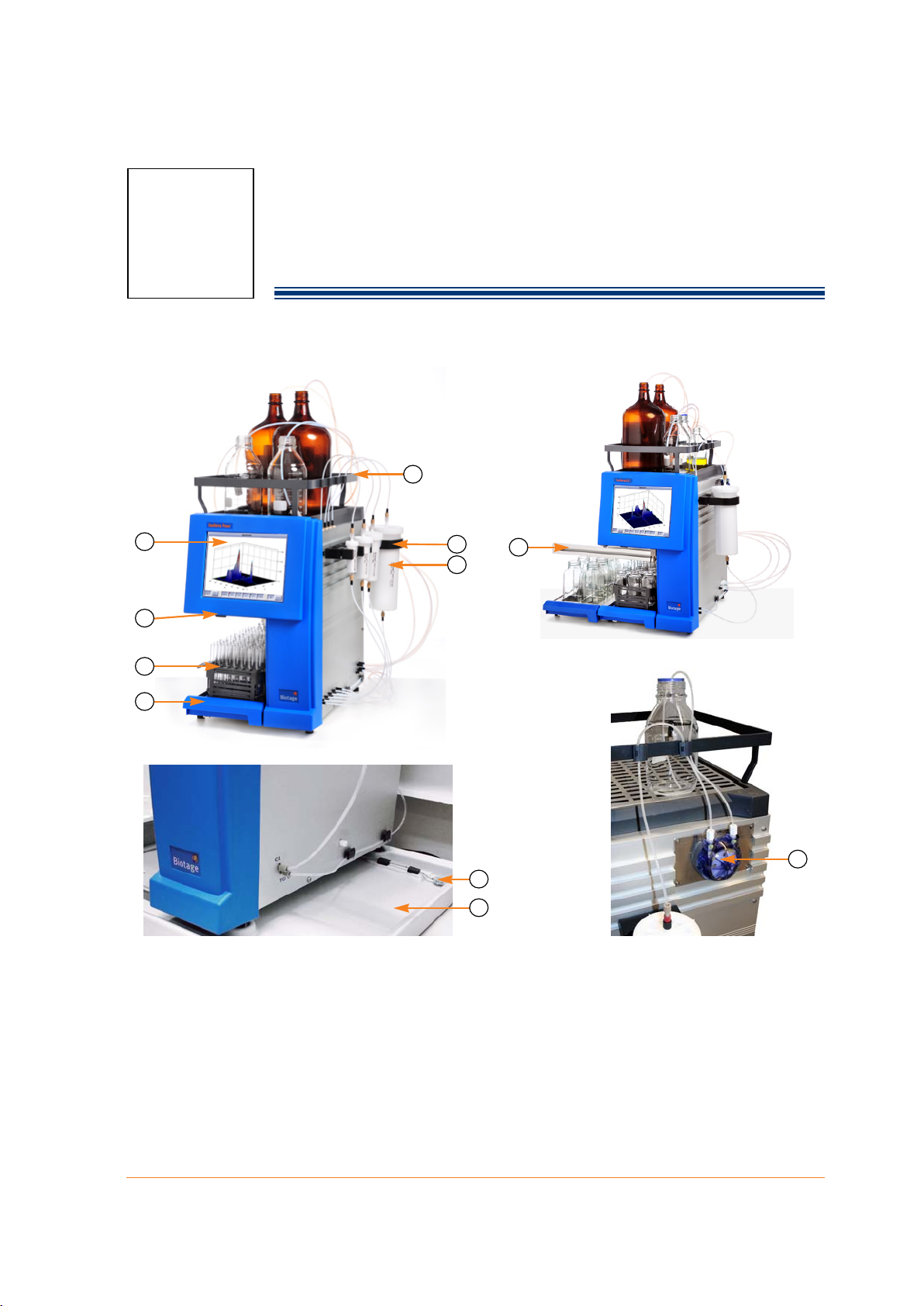
1.1 General System Description
Isolera Four Isolera LS
F
A
B
D
E
G
H
C
Sample Loading Pump
on Isolera LS
Biotage Leak Detector
K
I
J
A Touch Screen G Cartridge Holder
B Power Switch H SNAP Cartridge
C Collection Arm I Leak Detector (optional on Isolera Prime,
D Collection Rack J Leak Tray (optional)
E Collection Tray K Sample Loading Pump (only on Isolera LS)
F Solvent Tray
Figure 1-1. Isolera Systems
411829-L, Description and Specifications April 2012 Page 1-1
One, and Four and standard on Isolera LS)
Page 8
1
1.1.1 Basic System Components
The Isolera system is a high-performance flash chromatography system, consisting of the following
integrated components:
• A touch screen display, which is a solvent-resistant, color LCD screen with a resolution of
800 x 600 pixels. It serves both as a display and as the system’s input device via on-screen
touch controls.
• A fraction collector, which collects fractions into a wide variety of collection racks and vessels.
• A pump module, which directs liquid flow through the system. A default flow rate is specified
for each cartridge but, if desired, the flow rate can be changed. If the flow rate is increased,
the system will start the run at the default flow rate and then regulate towards the flow rate
defined in the method. Note that the system regulates on both flow rate and pressure. If
90% of the maximum allowed pressure is reached before the defined flow rate, the flow rate
at 90% pressure will be used.
• An internal detector, which provides the system with information on the light absorbance of
the solvents and samples passing through the detector flow cell. (It is also possible to
connect an external detector, e.g. Biotage ELSD-1080.)
1.1.2 System Configurations
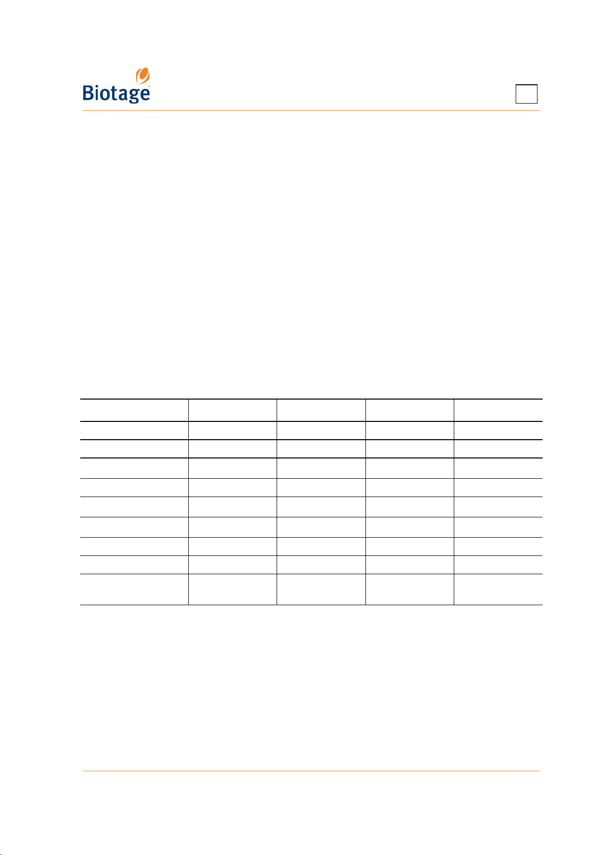
There are four system platforms available: Biotage Isolera Prime™, Biotage Isolera™ One, Biotage
Isolera™ Four, and Biotage Isolera™ LS (Large Scale). The differences are listed in the table below.
Table 1: System Differences
Isolera Prime* Isolera One*
Leak Detector: Optional Optional Optional Standard
Sample Loading Pump: No No No Yes
Collection Trays: 1
Solvent Inlets: 2 4 4 4
Cartridge Positions: 1
Waste Channels: 1
Pump Type: Single-piston Dual-piston Dual-piston Dual-piston
Flow Rate: 1 to 100 ml/min 1 to 200 ml/min 1 to 200 ml/min 50 to 500 ml/min
‡
Internal Detector:
* An Isolera Prime system can be upgraded to and Isolera One or Isolera Four system.
An Isolera One system can be upgraded to an Isolera Four system.
†
One collection tray is standard, but by expanding the fraction collector, it is possible to use two
collection trays (see Figure 1-1) at the same time. The maximum collection volume (with no rack
change) is then 9600 ml instead of 4800 ml (with the 480 ml bottle rack). These systems are called
EXP systems (Isolera One EXP and Isolera Four EXP).
‡
The internal detector is available in three models: 1) 200-400 nm (variable UV detector), 2) 200-800
nm (UV-VIS), and 3) 254 nm (fixed UV detector). Note that the UV-VIS detector is not available with
Isolera Prime and the fixed UV detector is not available with Isolera LS.
Fixed or variable
Fixed, variable, or
1 or 2
1
1
UV-VIS
†
‡
Isolera Four Isolera LS
†
1 or 2
41
41
Fixed, variable, or
UV-VIS
‡
Variable or UV-
VIS
2
‡
Biotage Leak Detector is available for safe, unattended operation. The sample loading pump, on
Isolera LS, can be used for injection of liquid samples into cartridges. This is useful when using
large cartridges and sample volumes.
411829-L, Description and Specifications April 2012 Page 1-2
Page 9
1
1.1.3 Programmed Functions
The Isolera system can be programmed to perform the following functions:
• Generate user-defined elution gradients
• Store and implement a large number of independent chromatographic methods
• Control and collect fractions based on light absorbance
• Collect fractions into a wide variety of collection racks and vessels
• Produce detailed, printable purification reports
1.1.4 User Documentation
The following documents are provided on the “Isolera User Documentation” CD (P/N 411831):
• “Isolera Installation and Safety”, P/N 411828
• “Isolera User Manual” (this publication), P/N 411829
• “Quick Guide for Isolera”, P/N 411830
• “Isolera Safety Translations”, P/N 412861
Online Help
To view context-sensitive help, press the Help button found in the right-hand panel. The following
buttons are available in the help window:
: View the safety requirements for the Isolera system. You must observe all these safety
requirements when installing and operating the Isolera system. Failure to install or use the system
in a manner specified by Biotage may result in personal injury and/or equipment damage.
: View instructions for tasks that can be performed in the present software mode (the Chemistry,
Data Administration, or System mode).
: View information on the tabs and buttons in the right-hand panel.
/ : Scroll down or up through the text (when a help window has more than one screenful of
information).
Back: Return to the last help topic that you viewed.
Close: Exit the help.
1.1.5 Accessories
Cartridges
The Isolera system is designed to operate with Biotage SNAP™, Biotage SNAP Ultra™ and Biotage
ZIP™ cartridges, which have easy-to-use Luer-lok™ connections. FLASH+
cartridges can also be used but may require tube adapters and a separate ring stand.
All SNAP and SNAP Ultra disposable cartridge components are made from materials meeting USP
Class VI specifications, which minimize organic extractables providing cleaner fractions.
SNAP cartridges are available packed with silica (KP-Sil), high-performance silica (HP-Sil), C
C18-HS), or NH (KP-NH) media. SNAP 750g and 1500g are available packed with silica (KP-Sil), C
(KP-C18-HS), or NH (KP-NH). Biotage ZIP cartridges are all packed with silica (KP-Sil).
SNAP Ultra cartridges deliver double the purification capacity of other flash cartridges by utilizing
™
Biotage HP-Sphere
higher surface area provides twice the loading capacity of lower surface area silicas. This improved
load capacity means that a smaller SNAP Ultra cartridge can be used to replace a more expensive and
larger competitive cartridges.
, small particle, 25 μm spherical silica with a 40% increase in surface area. The
®
and ISOLUTE®
18
(KP-
18
411829-L, Description and Specifications April 2012 Page 1-3
Page 10
1
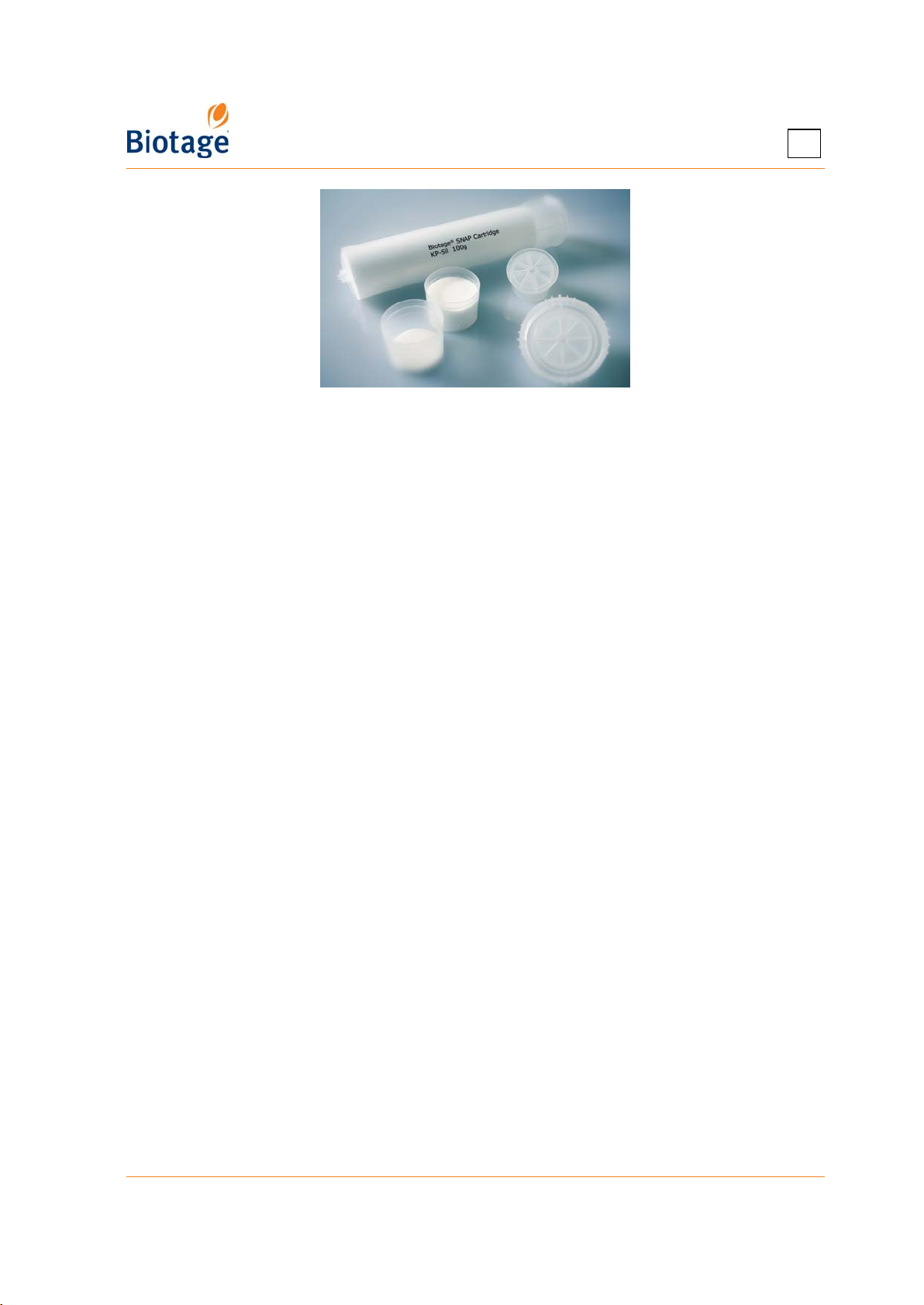
Figure 1-2. SNAP 100g Cartridge and Samplets
Note that SNAP and SNAP Ultra 10g to 30g and Biotage ZIP 5g to 45g cannot be used on Isolera LS,
and SNAP 1500g is not recommended for use on Isolera Prime, Isolera One, or Isolera Four. SNAP
750g, Flash 75S, Flash 75M, and Flash 75L are not recommended for use on Isolera Prime.
Sample Loading Methods for SNAP and SNAP Ultra Cartridges
Biotage SNAP and SNAP Ultra cartridges offer several types of loading techniques including three
internal dry loading options.
Liquid Loading
Liquid samples can be:
• Injected into the SNAP or SNAP Ultra cartridge inlet Luer fitting using a syringe or, when using
an Isolera LS system, the sample loading pump.
• Loaded onto the frit using a pipette (not possible when using SNAP 750g or 1500g).
Samples should be dissolved at the highest concentration in the weakest solvent. Use of a strong,
polar solvent will compromise purification efficiency.
Internal Dry Loading
If internal dry loading is to be used (not possible with SNAP 750g and larger cartridges), the
cartridge insert must be removed. Internal loading can be achieved using:
• Prepacked Samplet
Prior to insertion, the solvent should be evaporated in open air or in vacuum. Prepacked Samplet
cartridges are available in the same media types that are available for the cartridges.
• Empty Samplet cartridges.
If media other than those available in prepacked Samplet cartridges is required (e.g. scavenger
or catch-and-release resin, or other media), it can be easily packed into empty Samplet
cartridges.
• Bulk loading.
Dried, preadsorbed sample on media is added directly to the top of the cartridge. Specific media
amounts are required; see the documentation supplied with the cartridge.
External Dry Loading
Dried, preadsorbed sample on media can be loaded externally using a DLV-030, DLV-070, DLV-500
(for SNAP 750g and larger cartridges). They all attach directly to the SNAP
inlet Luer fitting; DLV-500 uses a tube connection. For further information, see the user
documentation supplied with DLV-30 and DLV-70 (P/N 413107), and DLV-500 (P/N 412625).
®
cartridges, which are inserted into the SNAP or SNAP Ultra cartridge.
or SNAP Ultra
cartridge
411829-L, Description and Specifications April 2012 Page 1-4
Page 11
1
Sample Loading Methods for Biotage ZIP Cartridges
Liquid samples can be injected into the Biotage ZIP cartridge inlet Luer fitting using a syringe or,
when using an Isolera LS system, the sample loading pump.
Dried, preadsorbed sample on media can be loaded externally using a dry load vessel (DLV-030 or
DLV-070).
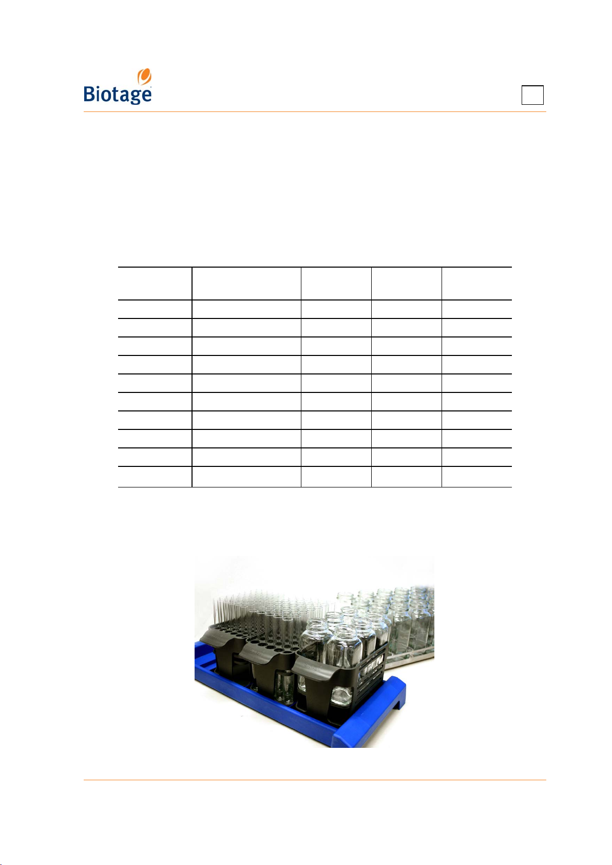
Collection Racks and Vessels
The Isolera software comes with a preconfigured list of Biotage collection racks. The vessel size
range is from 9 ml test tubes to 480 ml bottles. You may add other racks to this list (see “Add a
Rack Type” on page 2-5).
Rack Type
13 x 100 mm* 13 mm x 100 mm 9 ml 48 4
16 x 100 mm* 16 mm x 100 mm 14 ml 35 4
18 x 130 mm 17.5 mm x 130 mm 18 ml 28 4
16 x 150 mm* 16 mm x 150 mm 22 ml 35 4
18 x 150 mm 18 mm x 150 mm 27 ml 28 4
25 x 150 mm 25 mm x 150 mm 45 or 53 ml 15 4
120 ml 120 ml bottles 120 ml 6 4
240 ml 240 ml bottles 240 ml 18 1
480 ml 480 ml bottles 480 ml 10 1
Funnel rack
* Only included in the preconfigured list for Isolera Prime, Isolera One, and Isolera Four. Not
recommended on Isolera LS.
†
Only included in the preconfigured list for Isolera LS.
†
Vessel Diameter x
Length
Any vessel up to 10 l Up to 10 l 32 1
Vessel
Volume
No of
Vessels
No of Racks
per Tray
Figure 1-3. Typical Racks Used with Isolera
411829-L, Description and Specifications April 2012 Page 1-5
Page 12
1
Isolera LS Funnel Rack Kit
The maximum collection volume for Isolera LS can be increased from 9.6 liters up to 320 liters by
using a funnel rack kit from Biotage. The funnel rack kit comes with two racks (16 positions each)
and a cart with wheels that holds the Isolera LS system and the collection vessels. For more
information, please contact your local representative.
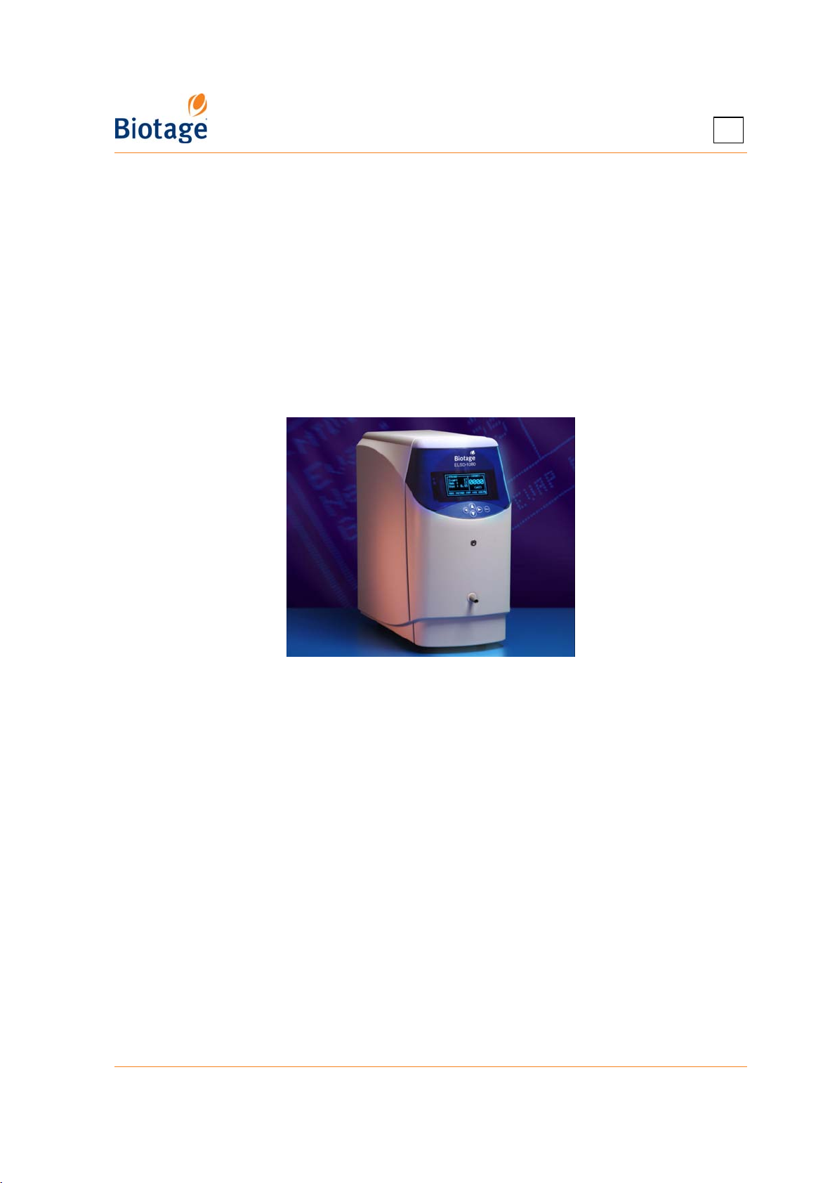
Biotage ELSD-1080 Detector
ELSD-1080 (evaporative light-scattering detector) is a universal detector designed for use with
Isolera One and Isolera Four systems when purifying compounds with little or no UV absorption
such as carbohydrates, steroids, lipids, and terpenes.
ELSD-1080 provides intelligent method design which enables the chemist to independently set
nebulizer and evaporator temperatures for a particular compound or compound class. Independent
temperature control helps ensure that all compounds are detected.
Figure 1-4. Biotage ELSD-1080 Detector
Order Accessories
To order accessories, please contact your local representative. A condensed accessory list is
available on page 5-1.
411829-L, Description and Specifications April 2012 Page 1-6
Page 13
1
1.2 Software Description
1.2.1 Main Menu
The system’s main menu provides access to the three different software modes:
• Chemistry: Set up, control, monitor, and review a purification.
• Data Administration: Administrate cartridge types, methods, rack types, results, solvents,
and user accounts.
• System: Change detector, network, reporting, and runtime settings, set the system clock, set
the language used in the Chemistry mode, enable the λ-all detection mode and the TLC to
Step Gradient editor (requires a Spektra license), calibrate the touch screen, fraction
collector, and internal detector, perform an intensity scan of the internal detector, release
stuck check valves, clean the collect valve, back up and restore the database, export system
logs, view and reset usage statistics, etc.
The main menu also provides software version information through its About button, access to
context-sensitive help through its Help button, and contains the Shut Down button, which is used
in the system shutdown process.
NOTE
Only users with system owner privilege can log into the Data
Administration and System modes.
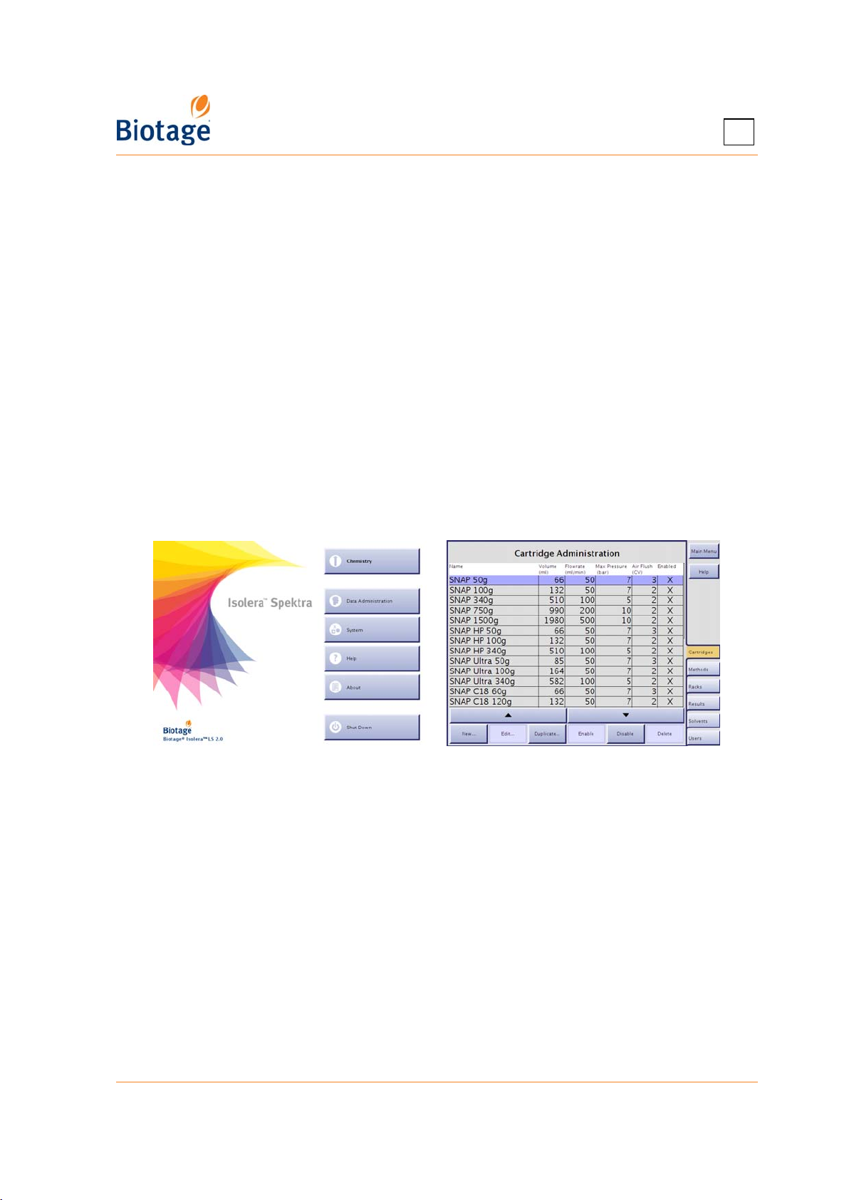
Figure 1-5. Main Menu and Data Administration Mode (Isolera LS Shown)
1.2.2 Data Administration Mode
In the Data Administration mode, the software is divided into six (6) tabs that can be accessed in
the right-hand panel (see Figure 1-5). Here is a short description of what you can do at each tab:
• Cartridges: Add, edit, and delete user defined cartridge types. It is also possible to select
the cartridge types that will appear in the cartridge selection list when setting up a method in
the Chemistry mode.
• Methods: Export, import, and delete methods. It is also possible to set default methods, i.e. a list
of methods that the users can choose from when creating a new method in the Chemistry mode.
• Racks: Add, edit, and delete user defined rack types. It is also possible to select the rack types
that will appear in the rack selection list when setting up a method in the Chemistry mode.
• Results: Export and delete result records, and clean up the system’s database. The records
can be exported as CSV files (comma-delimited text files), PDF files, and XML files.
• Solvents: Add, edit, and delete user defined solvents. It is also possible to select the solvents
that will appear in the solvent selection list when setting up a method in the Chemistry mode.
• Users: Add, edit, and delete user accounts.
411829-L, Description and Specifications April 2012 Page 1-7
Page 14
1
Buttons in the Right-hand Panel
The following buttons are available in the right-hand panel:
• Main Menu: Go to the main menu to enter the System mode, enter the Chemistry mode,
view software version information, or shut down the system.
• Help: View context-sensitive help.
1.2.3 System Mode
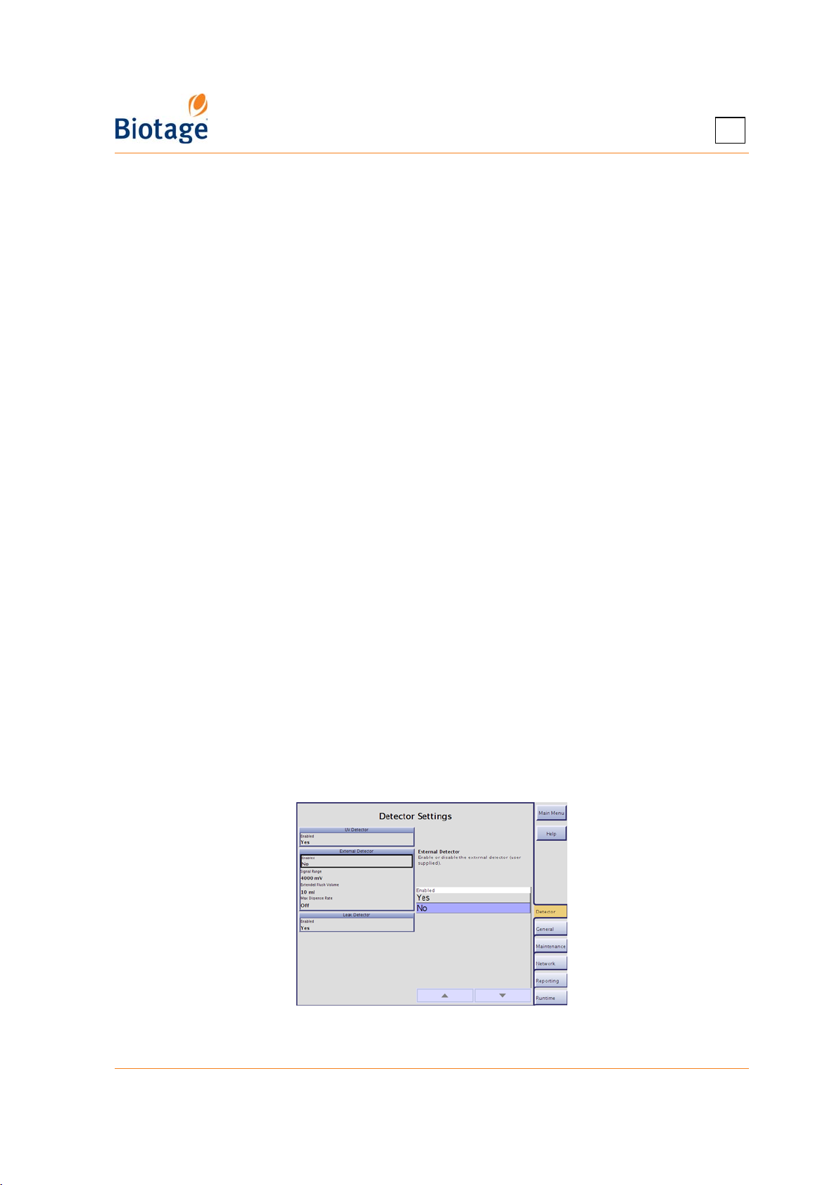
In the System mode, the software is divided into six (6) tabs that can be accessed in the right-hand
panel (see Figure 1-6). Here is a short description of what you can do at each tab:
• Detector: Enable or disable the internal detector, an external detector (e.g. Biotage ELSD-
1080), and Biotage Leak Detector.
• General: Set the system clock, the pressure unit to be used by the system (bar or psi), and
the language used in the software’s Chemistry mode, enable the λ-all detection mode and
the TLC to Step Gradient editor (requires a Spektra license), and enable or disable the mouse
pointer.
• Maintenance: Calibrate the touch screen, fraction collector, and internal detector, perform
an intensity scan of the internal detector, release stuck check valves, clean the collect valve,
back up and restore the database, export the system configuration and logs, restore the
system configuration, and view and reset usage statistics.
• Network: Configure a network connection and set up file sharing so that reports, methods,
backups, and the system configuration and logs can be saved in a share folder on your
network.
• Reporting: Connect a network printer with postscript support or a USB printer to the
system. It is also possible to enable or disable automatic printing, saving (in the share
folder), and e-mailing (to the e-mail address specified in the user’s account) of purification
reports.
• Runtime: Specify how flushes are performed, change collection and fractionation
parameters, and enable or disable automatic rack allocation, Peak Mode (in the status view),
auto extend of the gradient, audible alarm (e.g. when rack change is needed), solvent and
waste monitoring, and vessel, solvent, and waste estimation.
Buttons in the Right-hand Panel
The following buttons are available in the right-hand panel:
• Main Menu: Go to the main menu to enter the Data Administration mode, enter the
Chemistry mode, view software version information, or shut down the system.
• Help: View context-sensitive help.
Figure 1-6. System Mode
411829-L, Description and Specifications April 2012 Page 1-8
Page 15
1
1.2.4 Chemistry Mode
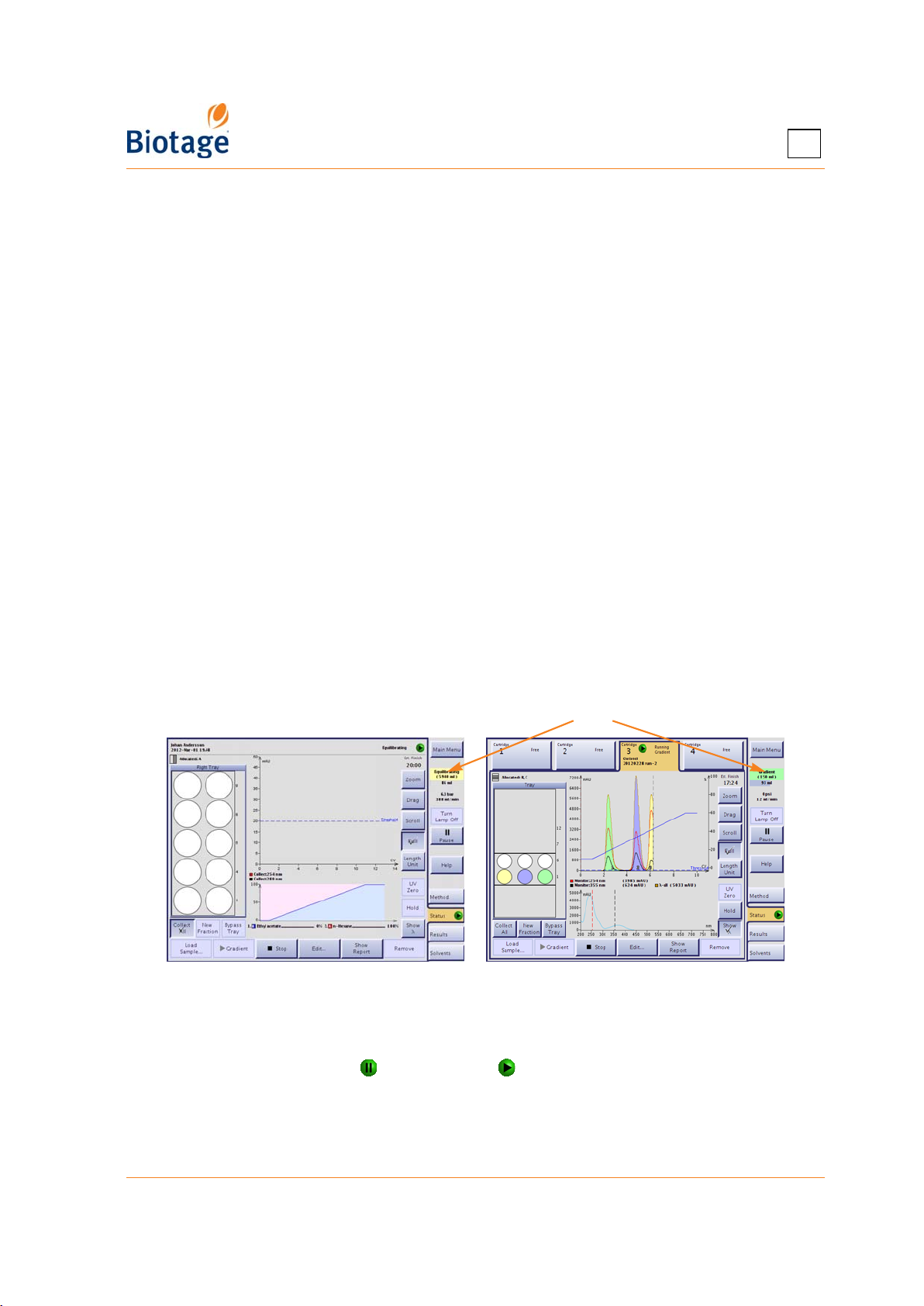
In the Chemistry mode, the software is divided into four (4) tabs that can be accessed in the righthand panel (see Figure 1-7). Here is a short description of what you can do at each tab:
• Method: Create, open, and edit a method, and assign it to a cartridge mounted on the
system, select the rack position(s) to be used, and start or queue up* the purification.
• Status: View information on a cartridge mounted on the system, monitor and edit the
purification in progress, enable injection of a liquid sample, and start or queue up* a
purification after a finished equilibration step. It is also possible to enable or disable the
Collect All mode, manually instruct the system to switch to a new collection vessel, start and
stop collecting through the waste channel, start and end an isocratic segment, change the
processing order of queued purifications*, and manually end (or abort) and remove a
purification.
• Results: Search and view the results of all purifications stored in the system’s database, on
a USB memory device (if connected), or in a share folder on your network (if connected).
Result reports can be printed to a network printer with postscript support or a local USB
printer and saved as PDF files on a USB memory device or in a share folder on your network.
It is also possible to create a new method with the same purification parameters as the ones
used in a previous purification. If desired, the system can help you to optimize the gradient
to isolate one of the peaks and reduce the amount of solvent used.
• Solvents: Assign solvents to the solvent inlets, set the solvent and waste reservoirs’
volumes (if monitoring of solvent and waste are enabled), prime the solvent inlets and, when
using an Isolera LS system, control the sample loading pump. It is also possible to flush a
cartridge with air to empty it of remaining solvents
remaining pressure before unloading it.
* Purifications can be queued up when using an Isolera Four system.
†
The Air Flush feature is not available when using an Isolera Prime system.
†
and purge a cartridge to release any
Task field
Figure 1-7. Chemistry Mode (Isolera LS and
Isolera Four EXP with Spektra License Shown)
Status and Task Field
The system can be idle, paused ( ), or processing ( ). When the system is processing, the
following tasks can be in progress:
• UV ON: The system turns on the detector lamp(s).
• Eq. Flush: Before an equilibration is started, the system runs an equilibration flush to empty
the solvent inlets of solvents used in the previous purification and fills them with new solvents.
411829-L, Description and Specifications April 2012 Page 1-9
Page 16
• Equilibrating: The system is running an equilibration.
• UV Warm-up: The UV lamp is being warmed up. This takes approximately 7.5 minutes.
• UV Zero: The system is setting the UV zero level.
• Baseline Det.: The system is measuring the solvent absorbance of the gradient so that the
maximum solvent absorbance spectrum can be subtracted from the signal presented by the
detector during the gradient run. For more information on baseline correction, see “Specify
Collection Parameters at the Collection Tab” on page 4-8. (Only available on systems with a
Spektra license installed.)
• Gradient Flush: After a performing a baseline detection, the system flushes the system with
the solvent mix used in the start of the gradient.
• Sample Pump: The sample pump is in use. (Only available on Isolera LS.)
• Gradient: The system is running a purification. If the system is collecting on the tray, the
background color is green. If fractions are collected through the waste channel (i.e. the
Bypass Tray option is enabled), the background color is magenta.
• Line Flush, Air Flush, Purge, and Detector Flush: After the gradient purification stage is
completed, the system performs enabled flushes (in the System mode) and a system
decompression process (Purge). It is also possible to manually instruct the system to perform
an Air Flush and a Purge. Note that the Air Flush feature is not available with Isolera Prime.
• Prime: The system is priming the solvent inlet(s).
Buttons in the Right-hand Panel
The following buttons are available in the right-hand panel:
• Main Menu: Go to the main menu to enter the Data Administration mode, enter the System
mode, view software version information, or shut down the system.
• Turn Lamp On/Skip Warm Up/Turn Lamp Off: Manually turning the detector lamp(s) on
and off. The UV lamp should be turned on approximately 7.5 minutes before operation so it
can warm up and stabilize. When the lamp(s) has/have been manually turned on, the Turn
Lamp On button toggles to a Skip Warm Up button, which can be used when you want to skip
the UV lamp warm-up period and begin the run. However, if the UV lamp has not reached
operating temperature, purification results may not be optimal. To prolong lamp life, the
lamp(s) is/are turned off automatically if the system is idle (no purification is started and no
user interaction is detected) for approximately two hours.
• Pause/Resume: To pause a purification, press the Pause button. The collection arm returns
to its home position (the inner right corner), the system is paused, and the Pause button is
toggled to a Resume button. To resume the operation, press the Resume button.
1
WARNING
Keep your hands out of range of the collection arm until it has stopped
moving (with the collection arm in the inner right corner).
• Help: View context-sensitive help.
NOTE
Only users with system owner privilege can log into the Data
Administration and System modes.
411829-L, Description and Specifications April 2012 Page 1-10
Page 17
1
1.2.5 Method Tab (Chemistry Mode)
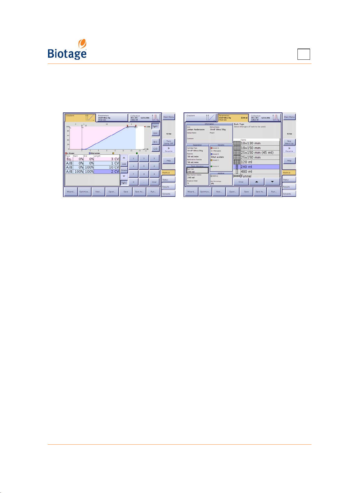
At the Method tab, in the software’s Chemistry mode, you can create, open, and edit a method,
and assign it to a cartridge mounted on the system, select the rack position or positions to be used,
and start or queue up* the purification.
Figure 1-8. Method Tab (Isolera LS Shown)
There are different ways of creating a new method:
• Create a new method. If using the method wizard, it will guide you step-by-step through
the setup of a run. You can also use the TLC to Linear Gradient editor or the TLC to Step
Gradient editor (requires a Spektra license) to calculate a purification gradient and get
cartridge and sample load recommendations. After setting up the method, you can save it by
entering a unique method name.
• Base the new method on an existing method. You can either base the method on one of
the preconfigured Biotage methods or a method created and saved in the system’s database,
on a USB memory device, or in a share folder on the network. After editing, you can save the
method under a new name by entering a unique method name. The original method remains
unaltered under its original name.
• Base the new method on a previous purification (at the Results tab). After editing the
purification parameters, you can save it by entering a unique method name.
NOTE
You do not have to save your method to be able to run it.
1.2.6 Status Tab (Chemistry Mode)
At the Status tab, in the software’s Chemistry mode, you can:
• View information on a cartridge mounted on the system. Available information is: user,
sample name, status, allocated rack(s), and the estimated time when the system will have
completed the purification.
• Enable injection of a liquid sample using a syringe or the sample loading pump (the Load
Sample button) and start or queue up* a purification after a finished equilibration step.
(Only Isolera LS is equipped with the sample loading pump.)
• Change the processing order of queued purifications.*
• Start and end an isocratic segment (the Hold button).
• Enable or disable the Collect All mode and manually instruct the system to switch to a new
collection vessel.
* Purifications can be queued up when using an Isolera Four system.
411829-L, Description and Specifications April 2012 Page 1-11
Page 18

1
• Monitor and edit a purification in progress. While a purification is running, the programmed
gradient and a dynamic chromatogram are displayed. The chromatogram can be magnified,
dragged to the desired position, etc. If a Spektra license has been installed on your system,
the absorbance spectrum for the whole detector range can be viewed in the gradient view by
pressing the Show λ button. The gradient is then displayed in the chromatogram.
• Start and stop collecting through the waste channel (the Bypass Tray button).
• Stop – end (the enabled flushes and a purge will be performed) or abort – a purification.
• Clear a cartridge position in the software (the Remove button).
WARNING
When pressing the Stop button, keep your hands out of range of the
collection arm until it has stopped moving (with the collection arm in the
inner right corner).
NOTE
If you want to end or abort a purification in progress, press the Stop
button.
It is not possible to edit a purification during the flushes and purge.
When using an Isolera Four system, queued equilibrations take priority
over queued gradient runs.
Cartridge Status
The status of a cartridge can be one of the following:
• Free: No purification is assigned to the cartridge.
• Queued Equilibration/Gradient Run*: The equilibration or gradient run is queued and will
be performed when the system has completed the task(s) in progress.
• Equilibrating: The system is running the equilibration.
• Equilibration Finished: The equilibration is completed. Press the Load Sample button to
load the liquid sample and then the Gradient button to start or queue up* the gradient run.
• Running Gradient: The system is running the gradient.
• Finished: The purification is completed.
• Manually Extended: The purification was manually extended after it was completed. Press
the Gradient button to start or queue up* the extended run.
* Purifications can be queued up when using an Isolera Four system.
NOTE
When using an Isolera Four system, queued equilibrations take priority
over queued gradient runs.
411829-L, Description and Specifications April 2012 Page 1-12
Page 19
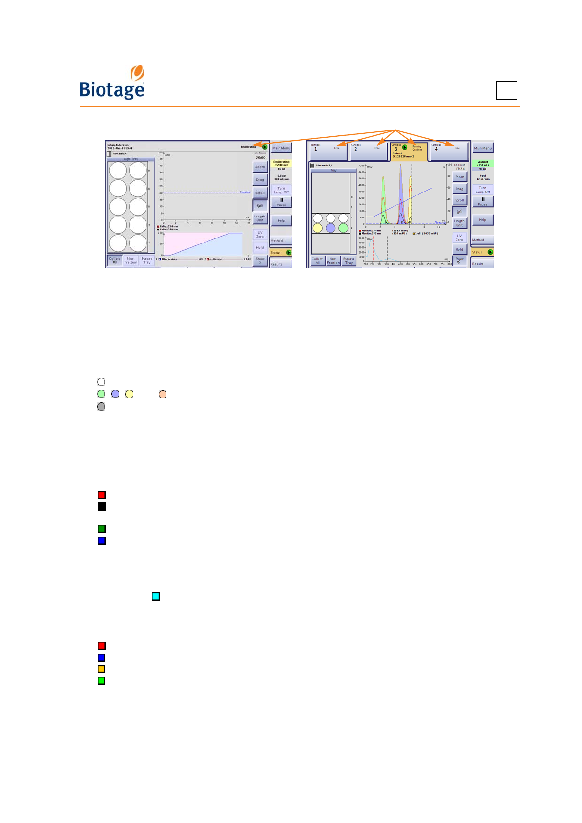
1
Cartridge status
Figure 1-9. Status Tab (Isolera LS and
Isolera Four EXP with Spektra License Shown)
Color Legends
Fractions
Fractions that are already collected can be located by matching their colors on the chromatogram
with the vessel colors in the tray overview:
= The vessel is allocated but has not been used.
, , , and = The vessel contains a fraction.
= The vessel contains flush liquid.
If fractions are collected through the waste channel (i.e. the Bypass Tray mode is enabled), the
fractions are colored in magenta in the chromatogram and numbered W1, W2, and so on.
Light Absorbance
Light absorbance and the Start Threshold (if defined) are displayed in the chromatogram using the
following colors:
= Absorption measured by the internal detector, channel 1.
= Absorption measured by the internal detector, channel 2. (Not available if using the fixed
detector.)
= Absorption measured by the external detector (when connected).
= The defined threshold in mAU.
The defined wavelengths and the measured absorption in mAU
chromatogram.
If a Spektra license has been installed on your system, the absorbance spectrum for the whole
detector range ( ) can be viewed in the gradient view by pressing the Show λ button.
Gradient Graph and Table
The colors used in the gradient graph and table are:
= Solvent A and the equilibration line (only in the graph).
= Solvent B and the gradient line in segments with Solvent A and B (only in the graph).
= Solvent C and the gradient line in segments with Solvent B and C (only in the graph).*
= Solvent D and the gradient line in segments with Solvent C and D (only in the graph).*
The gradient graph shows the defined gradient (excluding the additive*). The actual percentage of
pumped solvents (including the additive*, if used) are displayed underneath the graph.
* Not available when using an Isolera Prime system.
are displayed underneath the
411829-L, Description and Specifications April 2012 Page 1-13
Page 20
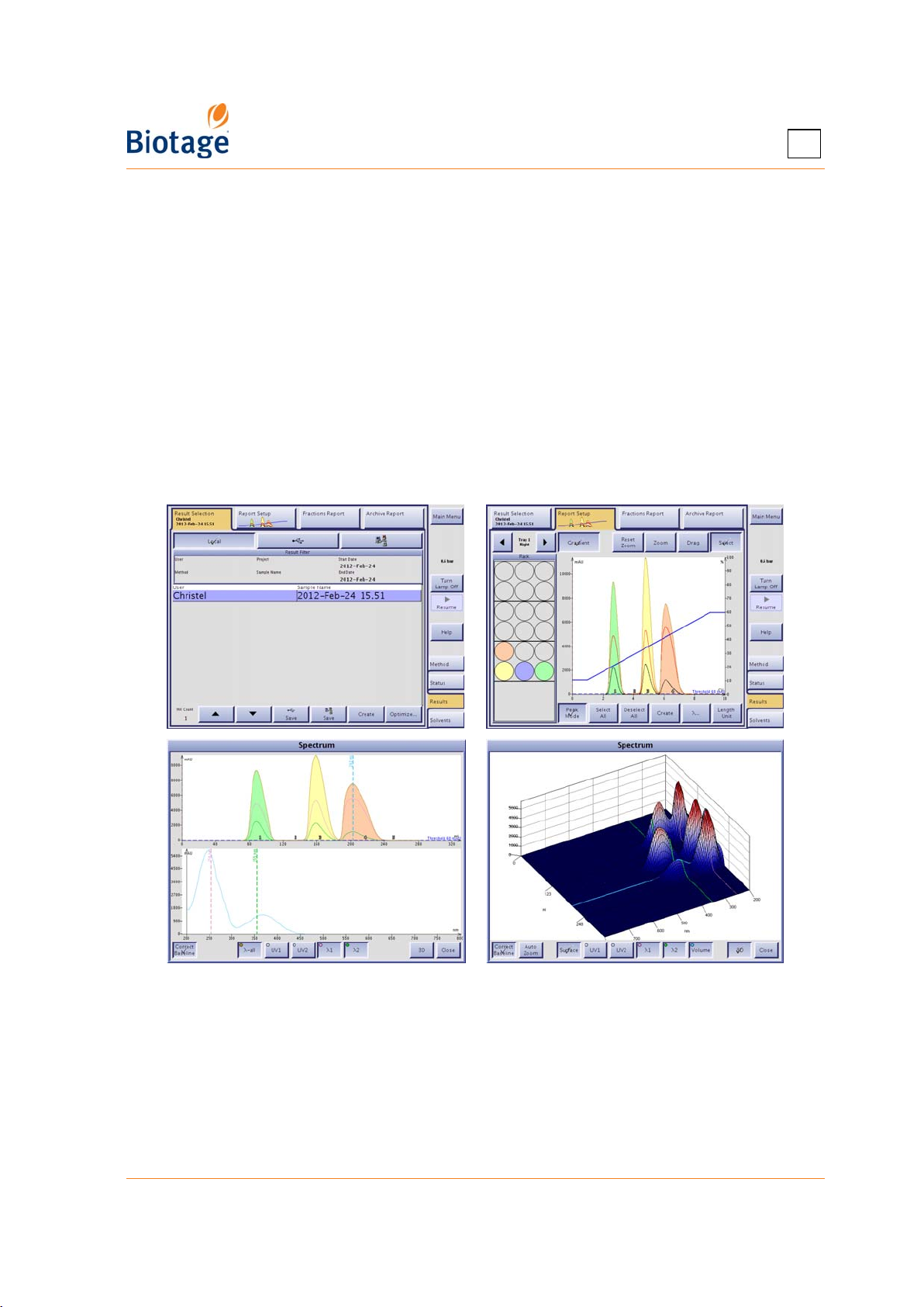
1
1.2.7 Results Tab (Chemistry Mode)
Purifications that are processed on the system are stored as individual records in the system’s
database. The records can, if desired, be saved by the user as XML files (text files including all raw
data) on a USB memory device or in a share folder on the network.
At the Results tab, in the Chemistry mode, it is possible to search and view the results of all
purifications stored in the system’s database, on a USB memory device (if connected), or in a share
folder on your network (if connected). Two result reports are available for each purification: 1) an
archive report with purification details, a chromatogram, a 3D absorbance spectrum for the whole
detector range (requires a Spektra license), TLC data (if entered in the TLC to Step Gradient editor)
and 2) a fraction report. These reports can be printed to a network printer with postscript support
or a local USB printer and saved as PDF files on a USB memory device or in a share folder on your
network.
At the Results tab, it is also possible to create a new method with the same purification
parameters as the ones used in a previous purification. If desired, the system can help you to
optimize the gradient to isolate one of the peaks and reduce the amount of solvent used.
Figure 1-10. Results Tab with Spektra License
Result and Fraction Selection
All records that match the specified filter settings are listed at the Result Selection tab. Select the
record you want to view; both a fraction and an archive report are displayed. If a record that you
want to view is not listed, change the filter settings by pressing the Result Filters field. Possible
search criteria are 1) user name, 2) project name, 3) method name, 4) sample name, and 5) date
when the purification was run. Note that the result filter is case sensitive.
411829-L, Description and Specifications April 2012 Page 1-14
Page 21
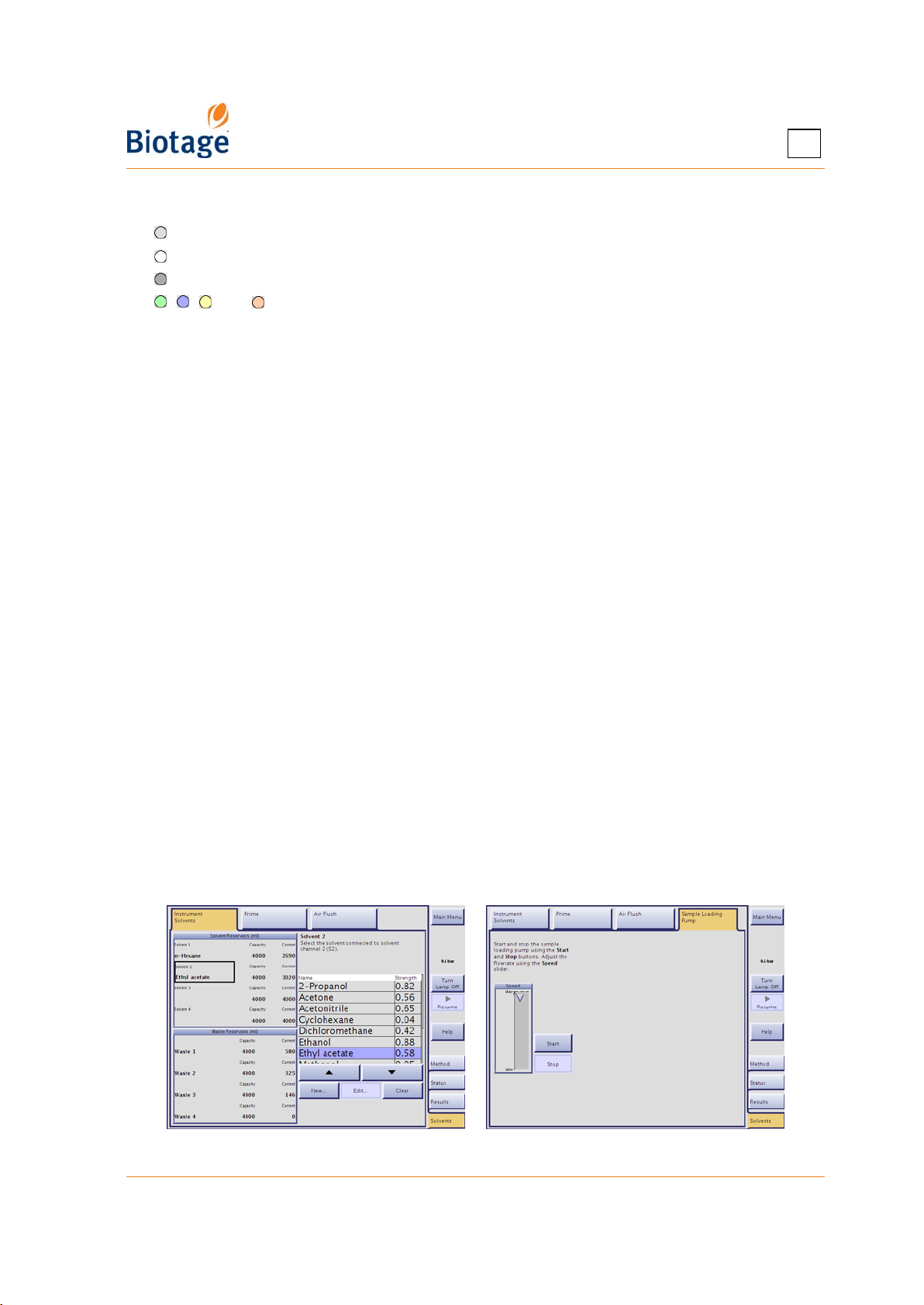
1
At the Report Setup tab, you can select the fractions to be displayed in the reports. The colors
used in the tray overview are:
= The vessel has not been used for the viewed purification.
= The vessel is deselected.
= The vessel is selected and contains flush liquid.
, , , and =The vessel is selected and contains a fraction. (The vessel color corresponds
with the fraction color in the chromatogram.)
If a Spektra license has been installed on your system, you can view a 2D and 3D absorbance
spectrum for the whole detector range by pressing the λ... button. Here you can also modify how
the 3D spectrum is presented in the archive report.
To create a method with the same purification parameters as the ones used in the selected record,
press the Create button at the Result Selection or Report Setup tab, or if you want help
optimizing the gradient, press the Optimize button.
1.2.8 Solvents Tab (Chemistry Mode)
At the Solvents tab, in the software’s Chemistry mode, you can:
• Assign a solvent to each of the solvent inlets on the right side of the system. When a
purification is run, the software references the solvent assignments to determine which
solvent inlets that are connected to the solvents used in the method. Therefore, it is
important that the solvents be assigned accurately. If you change the solvent that is
connected to a particular inlet, you must make the corresponding change in the software.
To assign a solvent, press the applicable Solvent text box.
• Enter the capacities and current fluid levels for the waste and solvent reservoirs
each time you empty a waste reservoir or replenish a solvent. The system will issue a
warning when it is time to replenish a solvent or empty a waste reservoir. To enter values,
press the applicable text box. (This feature is only available if the monitoring of solvent and
waste are enabled, see “Enable or Disable Monitoring of Reservoirs” on page 3-9.)
• Prime the solvent inlets to 1) remove any air bubbles from the pump and solvent inlets by
flushing them with solvents or 2) empty the solvent inlets of solvents used in the previous
purification and fill them with new solvents.
• Flush a cartridge with air to empty it of remaining solvents before unloading it. This
feature is not available with Isolera Prime.
• Purge a cartridge to release any remaining pressure before unloading it.
• Control the sample loading pump when cleaning the pump tubing or emptying the tubing
of solvent and/or sample before replacing it. (Only Isolera LS is equipped with the sample
loading pump.)
Figure 1-11. Solvents Tab (Isolera Four and Isolera LS Shown)
411829-L, Description and Specifications April 2012 Page 1-15
Page 22
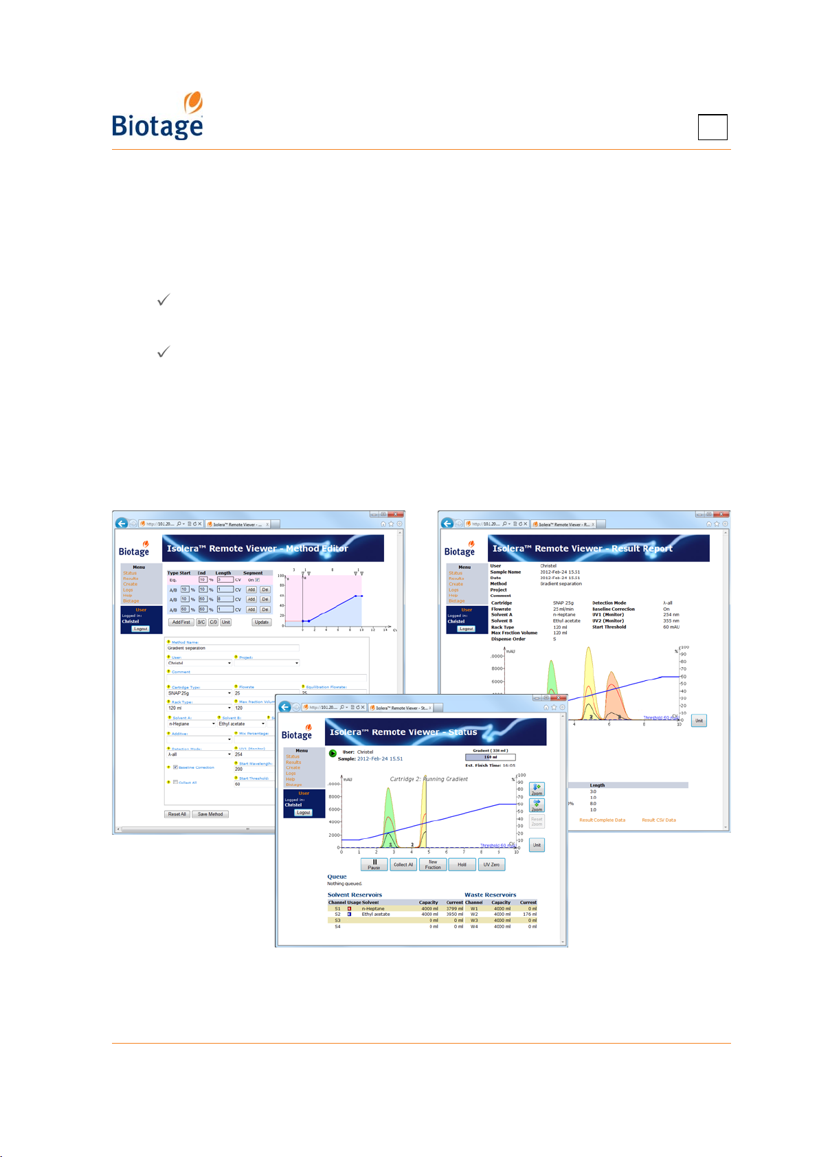
1
1.2.9 Isolera Remote Viewer
With the system connected to your network, it is possible to perform the following tasks through a
standard web browser (through the Isolera Remote Viewer feature):
• Create a new method. If desired, the method can be based on a previous purification found
in the Results view.
• Check the status of the system and the progress of a purification.
• Instruct the system to start and stop collecting fractions by clicking the Collect All button
( = fractions are collected).*
• Instruct the system to switch to a new collection vessel by clicking the New Fraction button.*
• Instruct the system to start and end an isocratic segment by clicking the Hold button
( = isocratic hold is enabled).*
• Instruct the system to pause the purification in progress by clicking the Pause button. For
safety reasons, it is only possible to pause and not resume a run from your office.
• Instruct the system to set the current UV level to 0 (zero) AU by clicking the UV Zero
button.*
• View, print, and export purification results.
* You must be logged in as the user defined in the purification run.
To access the Isolera Remote Viewer, see page 4-31.
Figure 1-12. Isolera Remote Viewer
(System with Four Solvent Inlets and Spektra License Shown)
411829-L, Description and Specifications April 2012 Page 1-16
Page 23
1.3 Specifications
1.3.1 General System Specifications
Power
Input Voltage 100-240 VAC, 50/60 Hz
Fuses 4.0 TA/250 V, P/N 411916 (2 required)
Max Power Consumed 200 VA
Certification
Certificates CE, UL, CAN/CSA
Directives LVD, Directive 2006/95/EC
EMC, Directive 2004/108/EC
WEEE, Directive 2002/96/EC
Standards EN 61010-1: 2001
EN 1127-1:2007
EN 61326-1:2006
CAN/CSA-C22.2 No. 61010-1-04
UL 61010-1:2004
1
Fluid Path (Wetted) Materials
The wetted parts of the system contain stainless steel, FFKM, PEEK, PP, PE, FEP, PTFE, silica, carbon fiber filled PTFE,
and fused silica, which are not affected by common chromatographic solvents.
The Isolera LS system is delivered with two kinds of peristaltic pump tubes. Ensure that the used peristaltic pump
tube is compatible with the solvents and sample to be used; see section 1.3.4 on page 1-20.
Dimensions and Weights
Dimensions Width: 355 mm (14") or, when using a system with two collection trays, 577 mm
Weights 30-35 kg (66-77 lbs) depending on system configuration
(22.7");
Height: 596 mm (23.5");
Depth: 497 mm (19.6")
At least three centimeters (one inch) of space should be maintained between the
system’s rear panel and other objects to allow proper ventilation.
Environmental
Location A laboratory fume hood with capacity to handle leakage of solvents. If using an Isolera
Temperature 15°C to 32°C (59°F to 89.6°F)
Humidity 20% to 95% at room temperature
LS Funnel Rack Kit, a walk-in fume hood must be used.
Interfaces
LAN port, two USB ports (2.0), mouse port, VGA port, external detector port, and leak detector port
411829-L, Description and Specifications April 2012 Page 1-17
Page 24
1.3.2 Operational Performance Specifications
Cartridge Positions
Isolera Prime, One, and LS1
Isolera Four 4 (with separate waste channels)
Solvents
1
Solvent Supply A maximum of 2 x 4 liter (Isolera Prime) or 4 x 4-liter (Isolera One, Four, and LS) non-
glass reservoirs on top of the system (the solvent tray). Larger reservoirs can be placed
on the side of the system. If using glass reservoirs, up to 2.5-liter reservoirs can be
placed on the solvent tray.
Fraction Collector
Fraction Volume Programmable from 1 to 9999 ml (Isolera Prime, One, and Four) or
Max Fraction Number 192 fractions with no rack change (384 with two collection trays), 13x100 mm racks
Max Total Volume 4800 ml with no rack change (9600 ml with two collection trays), 480 ml bottle racks
Rack Types 13x100 mm*, 16x100 mm*, 18x130 mm (for 17.5 x 130 mm test tubes)*,
5 to 99999 ml (Isolera LS), depending on rack type
If using Isolera LS with a funnel rack, the maximum total volume is 320 liter
16x150 mm*, 18x150 mm, 25x150 mm, 120 ml, 240 ml, 480 ml, and funnel rack
* Not recommended on Isolera LS.
†
Cannot be used with Isolera One or Isolera Four.
Internal Detector
Wavelength
Amplitude Range 0 to 6 AU (Absorbance Units); accuracy of ± 0.04 AU
Flow Cell Optical Path 0.3 mm
UV lamp Deuterium discharge, 25 W
Tungsten lamp 10 W (used with the UV-VIS detector)
200 nm to 400 nm (variable), 200 to 800 nm (UV-VIS), or 254 nm (fixed)
The UV-VIS detector is not available with Isolera Prime and the fixed UV detector is not
available with Isolera LS. (Isolera Prime can be upgraded to an Isolera One or Four system.)
†
Pump
Flow Rate Range 1 to 100 ml/min (Isolera Prime), 1 to 200 ml/min (Isolera One and Four), or 50 to 500
Pressure Range 0 to 10 bar (0 to 145 psig)
ml/min (Isolera LS), in 1 ml/min increments
Gradient
Gradient Precision ±3%(Isolera Prime) or ±2%(Isolera One, Four, and LS)
Sample Loading Pump (Isolera LS)
Flow Rate Range 0 to 200 ml/min
Pressure Range 0 to 2 bar (0 to 29 psig)
Display
Screen 10.4" LCD; TFT active matrix; 800 x 600 resolution
Touch Screen Solvent stable
411829-L, Description and Specifications April 2012 Page 1-18
Page 25
1.3.3 Solvent Specifications
Many solvents are considered to be hazardous to humans and the
environment, so take appropriate safety precautions when using them.
Comply with Material Safety Data Sheets (MSDS) and any other applicable
regulations for the safe use, handling, transporting, storage, and disposal
of these solvents.
1
WARNING
Selectivity
Solvent CAS No. EC No.
Acetone 67-64-1 200-662-2 0.56 6 (VIa) 330 3.6 247.4
Acetonitrile 75-05-8 200-835-2 0.65 6 (VIb) 190 1.4 93.6
Cyclohexane 110-82-7 203-806-2 0.04 0 210 1.5 103.4
Dichloromethane
(Methylene chloride)
Ethanol 64-17-5 200-578-6 0.88 2 (II) 210 1.3 90.0
Ethyl acetate 141-78-6 205-500-4 0.58 6 (VIa) 255 1.4 98.3
n-Heptane 142-82-5 205-563-8 0.01 0 210 0.7 47.4
n-Hexane 110-54-3 203-777-6 0.01 0 210 2.3 161.6
Methanol 67-56-1 200-659-6 0.95 2 (II) 210 1.9 129.7
2-Propanol 67-63-0 200-661-7 0.82 2 (II) 210 0.6 44.0
Tetrahydrofuran 109-99-9 203-726-8 0.57 3 (III) 220 2.5 172.4
Toluene 108-88-3 203-625-9 0.29 7 (VII) 286 0.4 29.1
Water 7732-18-5 231-791-2 1.00 0 190 0.3 23.4
1
Neue U. D. HPLC Columns Theory, Technology, and Practice, Wiley-VCH (1997).
2
Dean J. A. Lange’s Handbook of Chemistry, 15th edition, McGraw-Hill (1999).
3
Snyder L. R. and Kirkland J. J. Introduction to Modern Liquid Chromatography, Wiley (1979).
75-09-2 200-838-9 0.42 5 (V) 235 6.9 475.3
Strength
1,2
Class
3
UV Cutoff
(nm)
Vapor
Pressure at
20°C (psi)
Vapor
Pressure at
20°C (mbar)
411829-L, Description and Specifications April 2012 Page 1-19
Page 26
1
1.3.4 Chemical Resistance of the Peristaltic Pump Tube (Isolera LS)
The Isolera LS system is delivered with two kinds of peristaltic pump tubes. Ensure that the used
pump tube is compatible with the solvents and sample to be used.
NOTE
The peristaltic pump tube has limited use. To avoid the risk of crosscontamination and decreased pump performance, it is recommended that
the peristaltic pump tube is discarded after each run. If you still want to
reuse the peristaltic pump tube, clean the tube as soon as possible as
described in section 5.8.1 on page 5-5.
Solvent
Acetetic acid Yes No n-Heptane Limited Yes
Acetone Limited No n-Hexane No Yes
Acetonitrile Yes No Isopropanol Limited Yes
Ammonia Yes Yes Methanol Yes Yes
Dichloromethane No Yes Pyridine Limited Limited
Ethanol Yes Yes Toluene No Yes
Ethyl acetate Limited No Triethylamine No Yes
Formic acid Yes Yes Water Yes Yes
Limited: The peristaltic pump tube must be discarded after each run.
The chemical resistance was tested in room temperature as follows: The peristaltic tube was
1) weighed, 2) submerged in solvent for three hours, 3) dried and visually inspected, 4) submerged for
another three hours, 5) dried, visually inspected, and weighed, and 6) dried for 24 hours and weighed.
PharMed,
P/N 412480
Fluran,
P/N 412481
Solvent
PharMed,
P/N 412480
Fluran,
P/N 412481
411829-L, Description and Specifications April 2012 Page 1-20
Page 27
Chapter
Data Administration
(Data Administration Mode)
2
WARNING
Before performing any procedures in this chapter, please read and observe
the safety requirements in the “Isolera Installation and Safety” document
(P/N 411828). Failure to follow those requirements may result in personal
injury and/or equipment damage.
2.1 Log into the Data Administration Mode
You must log into the Data Administration mode to be able to administrate cartridge types,
methods, rack types, results, solvents, and user accounts.
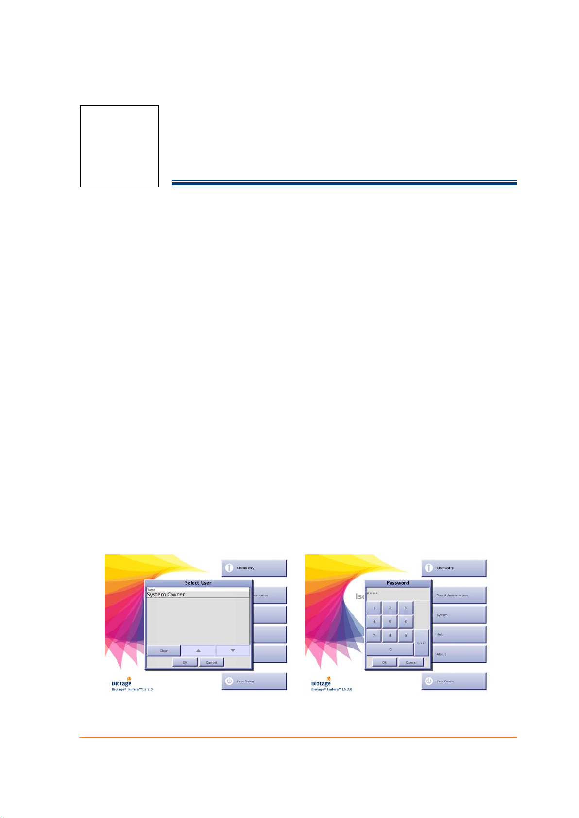
1. If you are not at the main menu, press Main Menu in the right-hand panel.
2. Press Data Administration. All user accounts with system owner privilege are listed in the
Select User dialog.
3. Select your user name. If you have not been assigned a user name and/or system owner
privilege, please contact your system supervisor.
4. Press OK. If your account is password-protected, the Password dialog opens.
a. Enter your password using the keypad. For the purpose of security, password characters
appear as asterisks.
b. Press OK. If you have entered a valid password, the software is opened in the Data
Administration mode.
For more information about the software modes, see “Software Description” on page 1-7.
NOTE
The first time you log into the Data Administration mode, log in using the
user account “System Owner” and the password “1234”. Before you log
out, it is strongly recommended that the password is changed (see
“Administrate the User List” on page 2-9).
Figure 2-1. Log into the Data Administration Mode
(Isolera LS with Spektra License Shown)
411829-L, Data Administration April 2012 Page 2-1
Page 28
2
2.2 Administrate the Cartridge List
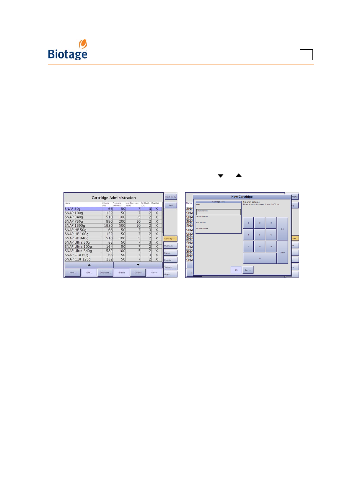
The software comes with a preconfigured list of cartridges and their settings. At the Cartridges
tab, in the software’s Data Administration mode, you may add other cartridges to this list, and
select the cartridge types that will appear in the cartridge selection list when setting up a method in
the Chemistry mode. It is also possible to edit and delete user defined cartridge types.
NOTE
The preconfigured Biotage cartridges cannot be edited or deleted.
SNAP and SNAP Ultra 10g to 30g and Biotage ZIP 5g to 45g cannot be used
on Isolera LS. SNAP 1500g is not recommended for use on Isolera Prime,
Isolera One, or Isolera Four. SNAP 750g, Flash 75S, Flash 75M, and Flash
75L are not recommended for use on Isolera Prime.
To scroll a list down or up, press or .
Figure 2-2. Cartridges Tab (Isolera LS Shown)
2.2.1 Add a Cartridge Type
1. Press New... or, if you want to base the new cartridge type on an existing one, select the
cartridge and press Duplicate... at the Cartridges tab. The New Cartridge dialog opens.
2. Enter the cartridge settings. (A setting can be entered when the corresponding text box has
been selected.) The cartridge parameters are:
• The name of the cartridge type.
• The column volume (CV) in ml.
• The default flow rate in ml/min.
• The maximum pressure in bar or psi (see “Set the Pressure Unit” on page 3-4). If the
maximum pressure is exceeded during a purification, the run will be paused and the
system has to be purged until an acceptable pressure level is reached.
• The air flush volume in CV.
3. To save the new cartridge type, press OK.
2.2.2 Delete an Unused Cartridge Type
1. Select the cartridge that you want to delete at the Cartridges tab.
2. Press Delete. The Confirm Delete dialog opens.
3. To confirm delete, press Yes.
411829-L, Data Administration April 2012 Page 2-2
Page 29
2
2.2.3 Edit a Cartridge Type
1. Select the cartridge that you want to edit at the Cartridges tab.
2. Press Edit.... The Edit Cartridge dialog opens.
3. Edit the cartridge settings. (A setting can be edited when the corresponding text box has been
selected.)
4. To save the changes, press OK.
2.2.4 Select Cartridge Types to List
1. If you want a cartridge type to appear when setting up a method in the Chemistry mode, select
it at the Cartridges tab and press Enable.
2. If you do
select it at the Cartridges tab and press Disable.
not want a cartridge type to appear when setting up a method in the Chemistry mode,
2.3 Administrate the Method List
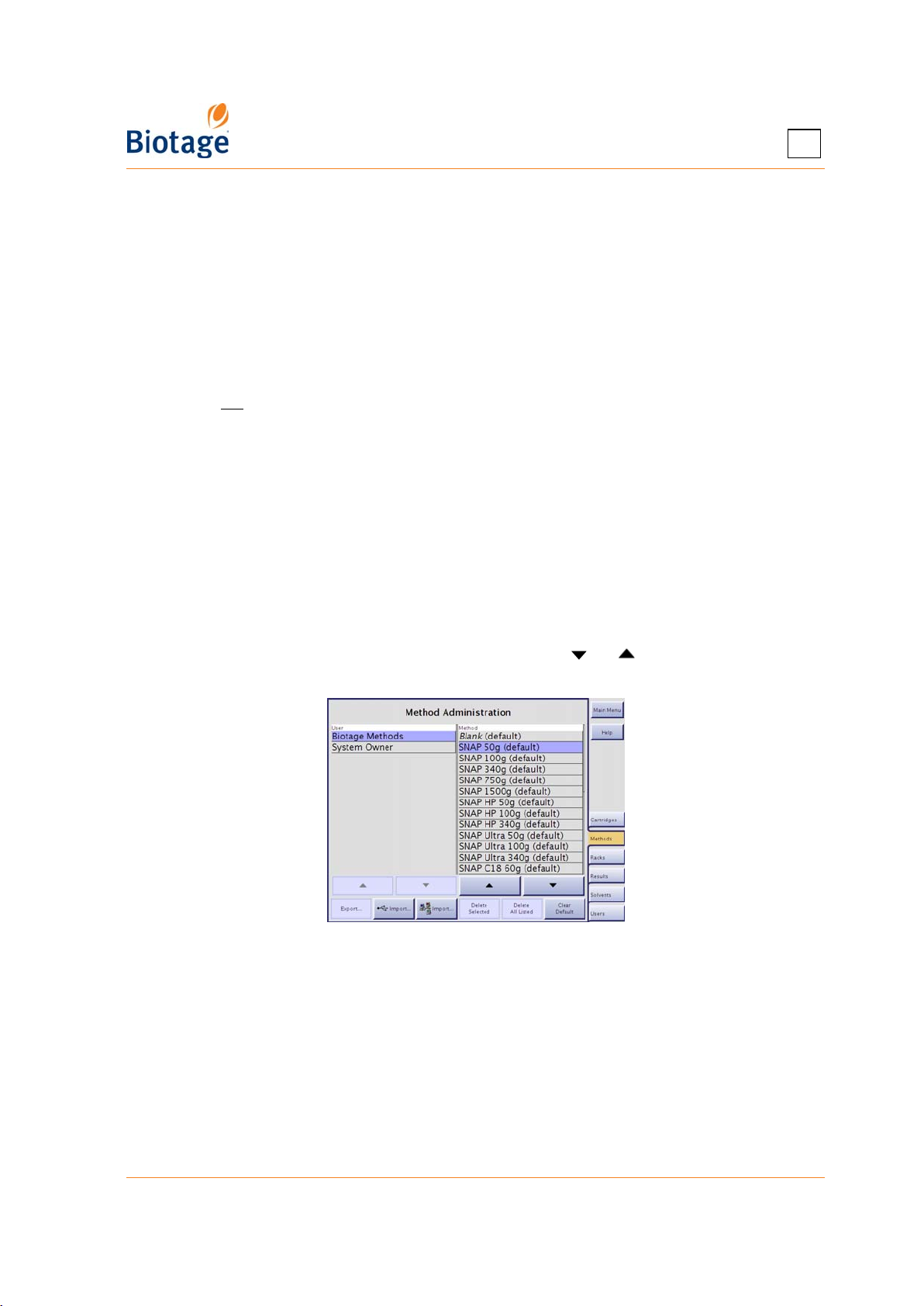
At the Methods tab, in the software’s Data Administration mode, all saved methods are listed. You
can export, import, and delete methods. It is also possible to set default methods, i.e. a list of
methods that the users can choose from when setting up a new method in the Chemistry mode.
(If the user wants to base a new method on a method that is not set as a default method, the user
will have to browse for the method.)
NOTE
The preconfigured Biotage methods cannot be exported or deleted.
To scroll a list down or up, press or .
Figure 2-3. Methods Tab (Isolera LS Shown)
2.3.1 Delete Methods
You can either delete a single method or all methods of a user.
1. Select the owner of the method(s) in the user list at the Methods tab.
2. If you want to delete a single method, select the method and press Delete Selected.
3. If you want to delete all methods of the selected user, press Delete All Listed.
4. To confirm delete, press Yes in the Confirm Delete dialog.
411829-L, Data Administration April 2012 Page 2-3
Page 30

2.3.2 Export Methods
You can export a single method, all methods of a user, or all saved methods to a USB memory
device or to a share folder on your network (if file share has been set up; see page 3-7).
1. If you want to export a single method, select the owner of the method in the user list at the
Methods tab and then select the method.
2. If you want to export all methods of a user, select the user at the Methods tab.
3. Press Export.... The Export Methods dialog opens.
4. Select the desired export option, Selected Method, All For Selected User, or All.
5. To save the method(s) to a USB memory device:
a. Connect the memory device to the USB port located underneath the touch screen.
b. Press Export.
6. To save the method(s) in the specified share folder, press Export. This button is only
available if file share has been set up; see page 3-7.
The methods are saved at \biotage\isolera\methods\.
2.3.3 Import Methods
NOTE
If you import a method with a solvent, cartridge, rack, user, or project that
is not available on the system, it will also be imported. The decision is
based on the name of the solvent, cartridge, etc., and will not consider
their settings.
2
You can either import a single method or all methods available on a USB memory device or in a
share folder on your network (if file share has been set up; see page 3-7). The method(s) to import
must be available at “USB”:\biotage\isolera\methods or “share folder”\biotage\isolera\methods.
1. If you want to import the method(s) to a certain user, select the user at the Methods tab.
2. To import method(s) available on a USB memory device:
a. Connect the memory device to the USB port located underneath the touch screen.
b. Press Import.... The Import Methods from USB dialog opens.
3. To import method(s) available in the specified share folder, press Import.... The Import
Methods from Network dialog opens.
4. To import a single method, select the method and then select Selected Method in the
Method(s) to Import list.
5. To import all methods, select All in the Method(s) to Import list.
6. Select import destination. You can either save the method(s) to the user selected in step 1,
To Selected User, or to the user defined in the method(s), To Original Users.
7. To import the method(s), press OK.
2.3.4 Set Default Methods
To set a method as a default method, i.e. add it to the list of methods that the users can choose
from when setting up a new method in the Chemistry mode:
1. At the Methods tab, select the method that you want to add to the list of default methods.
2. Press Set As Default.
To remove a method from the list of default methods:
1. At the Methods tab, select the method that you want to remove from the list of default methods.
2. Press Clear Default.
411829-L, Data Administration April 2012 Page 2-4
Page 31
2
2.4 Administrate the Rack List
The software comes with a preconfigured list of racks and their settings. At the Racks tab, in the
software’s Data Administration mode, you may add other racks to this list, and select the rack types
that will appear in the rack selection list when setting up a method in the Chemistry mode. It is also
possible to edit and delete user defined rack types.
NOTE
The preconfigured Biotage racks cannot be edited or deleted.
The funnel rack kit from Biotage can only be used with Isolera LS.
To scroll a list down or up, press or .
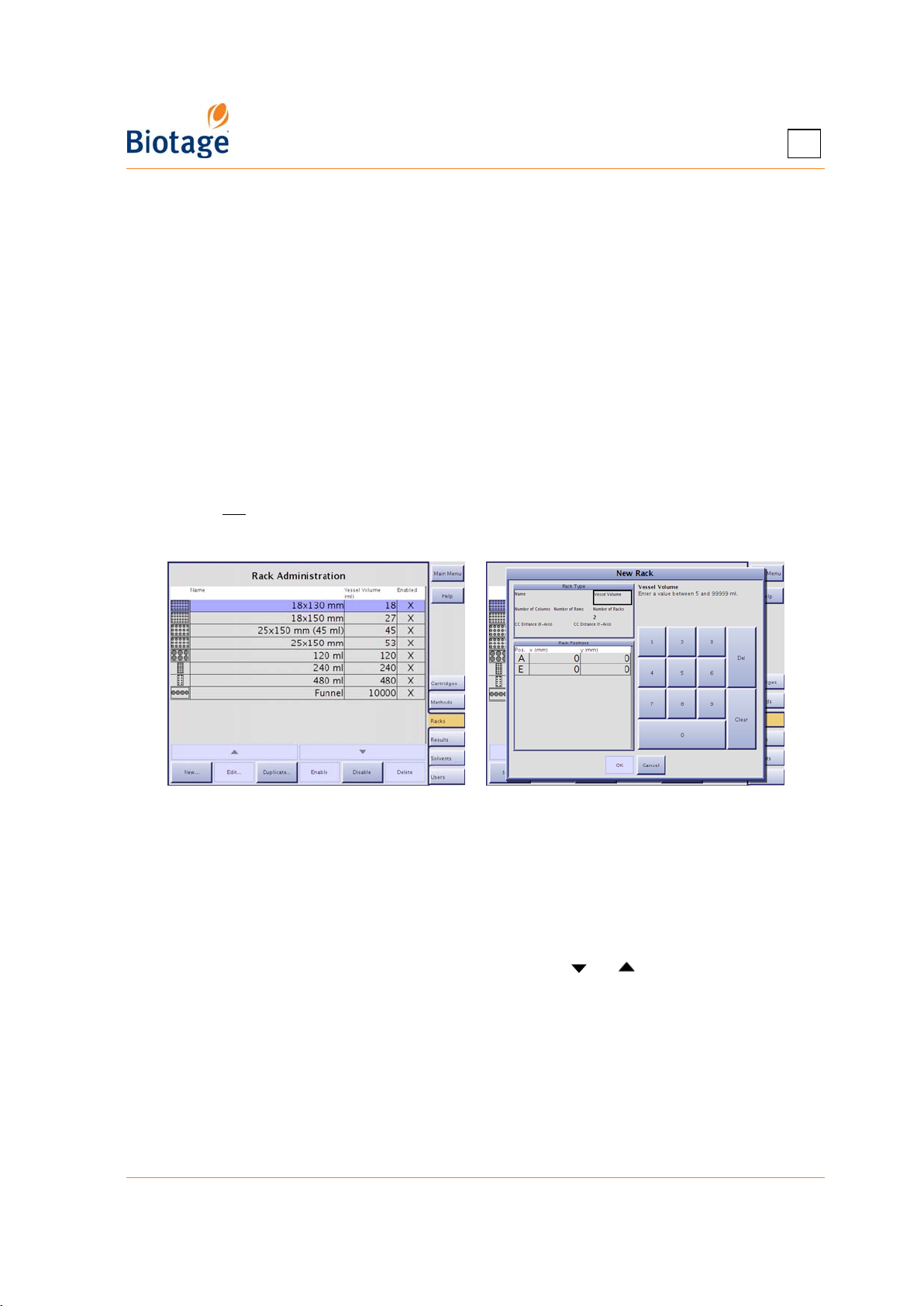
2.4.1 Add a Rack Type
1. Press New... or, if you want to base the new rack type on an existing one, select the rack and
press Duplicate... at the Racks tab. The New Rack dialog opens.
2. Enter the rack settings. (A setting can be entered when the corresponding text box has been
selected.) The rack parameters are:
• The name of the rack type.
• The vessel volume in ml.
•
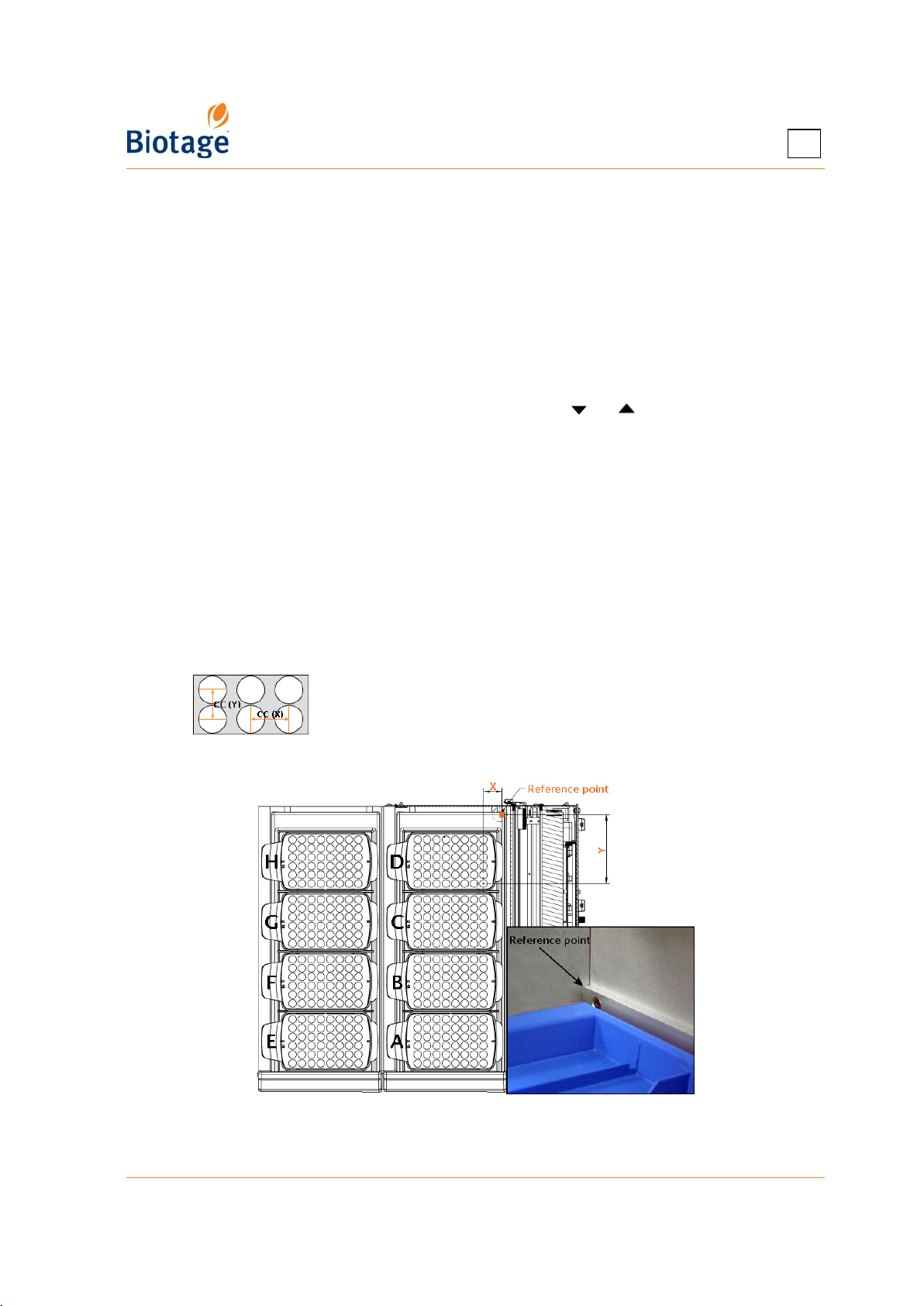
The number of columns and rows of vessels in a rack. For example, the racks in Figure 2-4
have six (6) rows and eight (8) columns each.
• The maximum number of racks that can be loaded onto a system with two collection
trays. Can be either two or eight, i.e. one or four racks per tray.
•
The CC distance between vessel positions along the x-axis and the y-axis; see image below.
• The x- and y-coordinates for the first vessel position of each rack on the collection area;
see Figure 2-4.
Figure 2-4. X- and Y-Coordinates for Rack Position D
3. To save the new rack type, press OK.
411829-L, Data Administration April 2012 Page 2-5
Page 32
2
2.4.2 Delete an Unused Rack Type
1. Select the rack that you want to delete at the Racks tab.
2. Press Delete. The Confirm Delete dialog opens.
3. To confirm delete, press Yes.
2.4.3 Edit a Rack Type
1. Select the rack that you want to edit at the Racks tab.
2. Press Edit.... The Edit Rack dialog opens.
3. Edit the rack settings. (A setting can be edited when the corresponding text box has been
selected.)
4. To save the changes, press OK.
2.4.4 Select Rack Types to List
1. If you want a rack type to appear when setting up a method in the Chemistry mode, select it at
the Racks tab and press Enable.
2. If you do
select it at the Racks tab and press Disable.
not want a rack type to appear when setting up a method in the Chemistry mode,
Figure 2-5. Racks Tab (Isolera LS Shown)
2.5 Administrate the Result List
Each purification is stored as an individual record in the system’s database. At the Results tab, in
the software’s Data Administration mode, you can export and delete result records and clean up the
system’s database.
NOTE
To scroll a list down or up, press or .
411829-L, Data Administration April 2012 Page 2-6
Page 33
2
2.5.1 Export and Delete Result Records
You can either export a single or all listed records to a USB memory device or to a share folder on
your network (if file share has been set up; see page 3-7). The records can be exported as CSV files
(text files including all detector data), PDF files, or XML files (text files including all raw data). CSV
files can be imported into Microsoft Excel or other applications that can handle comma-delimited
text files.
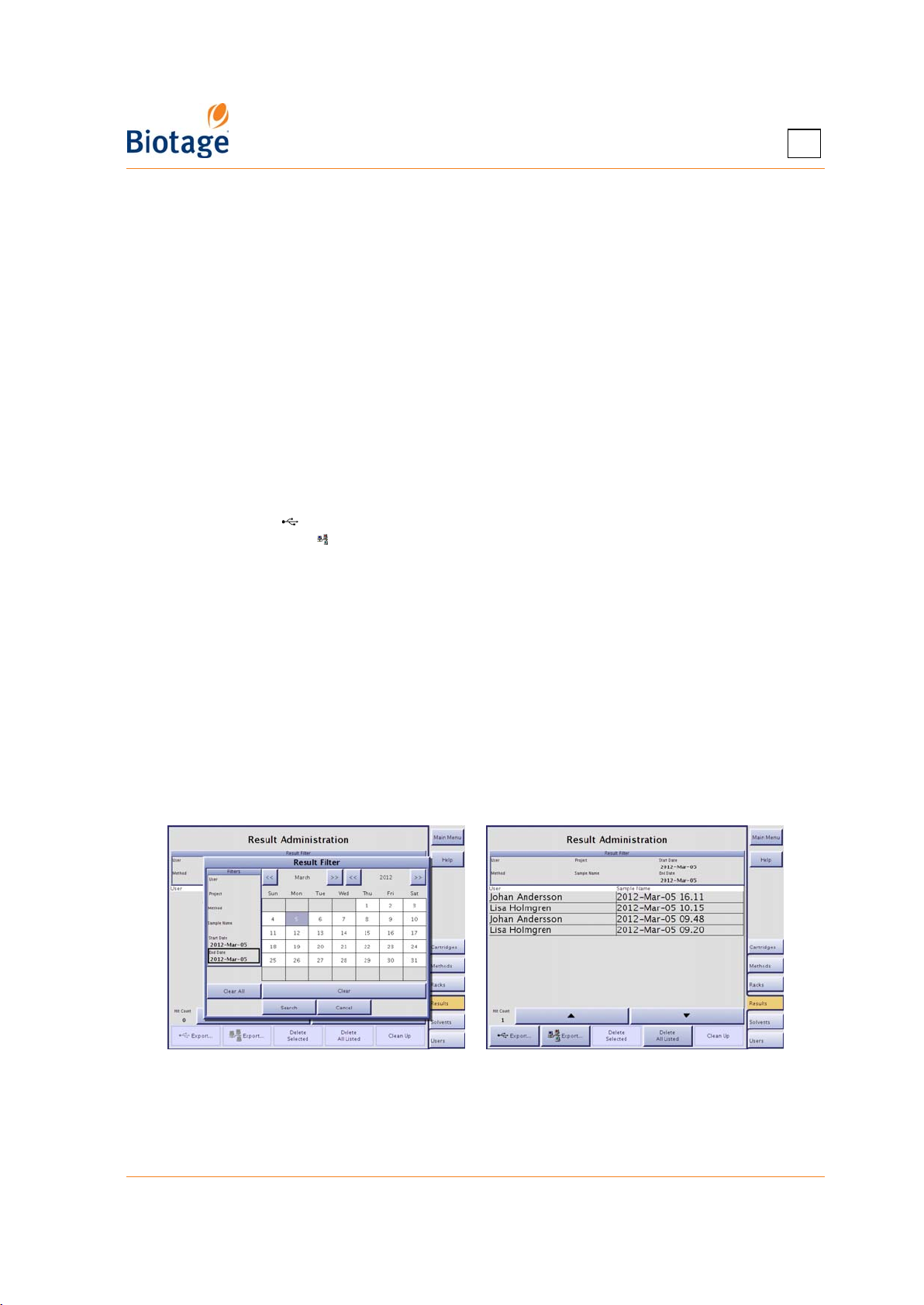
1. All records that fit the specified filter settings are listed at the Results tab. If a record that you
want to export or delete is not listed, change the filter settings:
a. Press the Result Filter field. The Result Filter dialog opens.
b. Specify the search criteria. (If you want to list all result records, press Clear All.)
c. To search, press Search. If there are records matching your filter settings, they are listed
in chronological order at the Results tab. Note that the result filter is case sensitive.
2. To export a single or all listed records as a CSV file (comma-delimited text file), PDF file, or a
XML file:
a. If you want to export the record(s) to a USB memory device, connect the memory device
to the USB port located underneath the touch screen.
b. If you want to export a single record, select it.
c. Either press Export... to export the record(s) to the USB memory device connected in
step 2a, or press Export... to export the record(s) to the specified share folder. The
Export Results dialog opens.
d. Select the desired export option, Selected or All Listed.
e. Press Export CSV, Export PDF, or Export XML.
3. To delete a single or all listed records:
a. To delete a single record, select it and press Delete Selected.
b. To delete all the listed records, i.e. delete all the records that fit the settings of the result
filter, press Delete All Listed.
c. To confirm delete, press Yes in the Confirm Delete dialog.
2.5.2 Clean Up the System’s Database
If the Clean Up button is enabled, there are one or more purifications available in the database
that cannot be displayed at the Results tab, likely due to power failure during a purification. To
remove the purification(s), press Clean Up.
Figure 2-6. Results Tab
411829-L, Data Administration April 2012 Page 2-7
Page 34
2
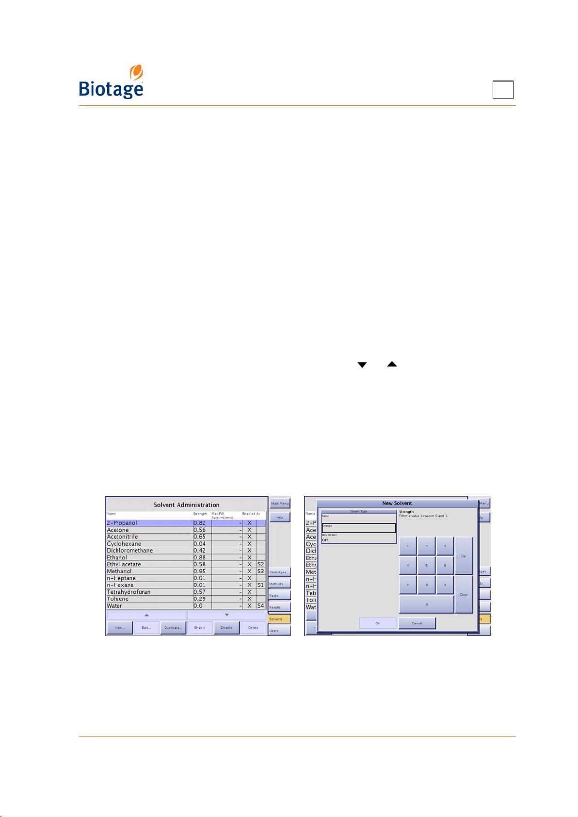
2.6 Administrate the Solvent List
The software comes with a preconfigured list of solvents and their settings. At the Solvents tab, in
the software’s Data Administration mode, you may add other solvents to this list, and select the
solvents that will appear in the solvent selection list when setting up a method in the Chemistry
mode. It is also possible to edit and delete user defined solvents.
The solvent parameters are:
• The solvent name.
• The solvent strength value, a value between 0 and 1.
• The maximum speed at which the solvent can be drawn into the pump during the fill stroke,
in ml/min. The valid range is 1 to 200 ml/min when using an Isolera Prime, Isolera One or
Isolera Four system and 50 to 500 ml/min when using an Isolera LS system. If this
parameter is turned off, the system’s maximum fill rate will be used (i.e. 200 ml/min or
500 ml/min).
1
Neue U. D. HPLC Columns Theory, Technology, and Practice, Wiley-VCH (1997).
2
Dean J. A. Lange’s Handbook of Chemistry, 15th edition, McGraw-Hill (1999).
NOTE
The preconfigured solvents cannot be edited or deleted.
To scroll a list down or up, press or .
1,2
2.6.1 Add a Solvent
1. Press New... or, if you want to base the new solvent on an existing one, select the solvent and
press Duplicate... at the Solvents tab. The New Solvent dialog opens.
2. Enter a unique solvent name, the solvent strength, and the maximum fill rate (i.e the maximum
speed at which the solvent can be drawn into the pump during the fill stroke) by selecting the
corresponding text box. To turn off the maximum fill rate and use the system’s maximum fill
rate, select the Max Fill Rate text box and press Off.
3. To save the new solvent, press OK.
Figure 2-7. Solvents Tab (System with Four Solvent Inlets Shown)
2.6.2 Delete an Unused Solvent
1. Select the solvent that you want to delete at the Solvents tab.
2. Press Delete. The Confirm Delete dialog opens.
3. To confirm delete, press Yes.
411829-L, Data Administration April 2012 Page 2-8
Page 35

2
2.6.3 Edit a Solvent
1. Select the solvent that you want to edit at the Solvents tab.
2. Press Edit.... The Edit Solvent dialog opens.
3. Edit the solvent settings. (A setting can be edited when the corresponding text box has been
selected.)
4. To save the changes, press OK.
2.6.4 Select Solvents to List
1. If you want a solvent to appear when setting up a method in the Chemistry mode, select it at
the Solvents tab and press Enable.
2. If you do
it at the Solvents tab and press Disable.
not want a solvent to appear when setting up a method in the Chemistry mode, select
2.7 Administrate the User List
At the Users tab, in the software’s Data Administration mode, you can add, edit, and delete user
accounts. The user parameters are:
Name: The user name will be used in the various user name selection boxes as well as in the
purification records. The user name is typically the person’s name, initials, employee number, etc.
Password: It is possible to password-protect a user account. The password will be used when
saving a method and, for users with system owner privilege, when entering the Data Administration
and System modes.
E-mail: If the system is connected to your network and the Auto Send Reports option is enabled
(see page 3-8), an e-mail with a result report will be sent to the e-mail address specified in the
user’s account when a purification has been completed. An e-mail will also be sent to the user when
user interaction is required, e.g. when a rack has to be replaced, a solvent needs to be replenished
(if monitoring is enabled), a waste reservoir needs to be emptied (if monitoring is enabled), and a
leak is detected (if using Biotage Leak Detector).
Privilege: A user can have chemist or system owner privilege:
• The chemist privilege gives the user access to the Chemistry mode, i.e. the user can set up
and run purifications, and view results.
• The system owner privilege gives the user both the chemist privilege (see above) and access
to the Data Administration mode (the user can administrate cartridge types, methods, rack
types, results, solvents, and user accounts) and to the System mode (the user can change
detector, network, reporting, and runtime settings, set the system clock, calibrate the touch
screen, fraction collector, and internal detector, perform an intensity scan of the internal
detector, release stuck check valves, back up and restore the database, export the system
configuration and logs, restore the system configuration, etc).
Performed Runs: The number of runs performed by the user.
NOTE
To scroll a list down or up, press or .
2.7.1 Add a User Account
1. Press New... or, if you want to base the new user account on an existing one, select the
account and press Duplicate... at the Users tab. The New User dialog opens.
2. Enter a unique user name, the password, the e-mail address, and the privilege by selecting the
corresponding text box.
3. To save the new user, press OK.
411829-L, Data Administration April 2012 Page 2-9
Page 36
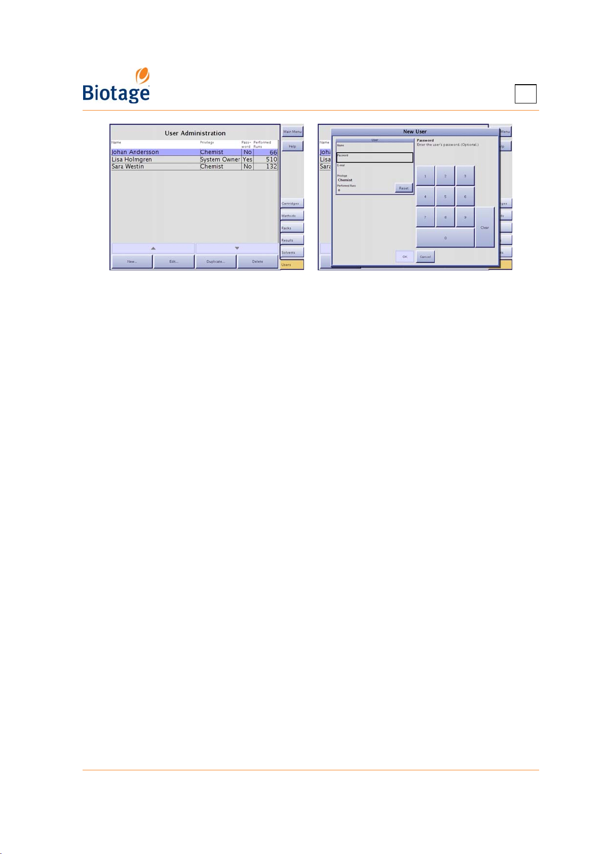
Figure 2-8. Users Tab
2.7.2 Change the Password or Privilege
1. Select the user account that you want to edit at the Users tab.
2. Press Edit.... The Edit User dialog opens.
3. Edit the user settings. (A setting can be entered when the corresponding text box has been
selected.) If you change the user name, all methods and result records associated with the user
will be updated.
4. To save the changes, press OK.
2
2.7.3 Delete a User Account
WARNING
All the results and methods of the user will also be deleted.
1. Select the user account that you want to delete at the Users tab.
2. Press Delete. The Confirm Delete dialog opens.
3. To confirm delete, press Yes.
2.7.4 Reset the Number of Performed Runs
1. Select the user account that you want to reset at the Users tab.
2. Press Edit.... The Edit User dialog opens.
3. Press Reset in the User field. The Reset Performed Runs dialog opens.
4. To confirm reset, press Yes.
411829-L, Data Administration April 2012 Page 2-10
Page 37
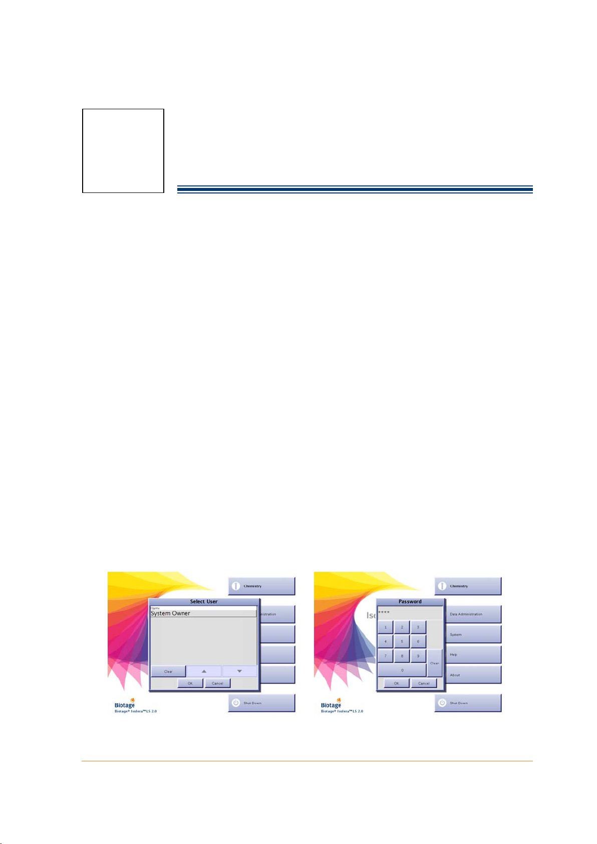
Chapter
System Settings
(System Mode)
3
WARNING
Before performing any procedures in this chapter, please read and observe
the safety requirements in the “Isolera Installation and Safety” document
(P/N 411828). Failure to follow those requirements may result in personal
injury and/or equipment damage.
3.1 Log into the System Mode
You must log into the System mode to be able to change detector, network, reporting, and runtime
settings, set the system clock, calibrate the touch screen, fraction collector, and internal detector,
perform an intensity scan of the internal detector, release stuck check valves, clean the collect
valve, back up and restore the database, export system logs, restore the system configuration, etc.
1. If you are not at the main menu, press Main Menu in the right-hand panel.
2. Press System. All user accounts with system owner privilege are listed in the Select User dialog.
3. Select your user name. If you have not been assigned a user name and/or system owner
privilege, please contact your system supervisor.
4. Press OK. If your account is password-protected, the Password dialog opens.
a. Enter your password using the keypad. For the purpose of security, password characters
appear as asterisks.
b. Press OK. If you have entered a valid password, the software is opened in the System mode.
For more information about the software modes, see “Software Description” on page 1-7.
NOTE
The first time you log into the System mode, log in using the user account
“System Owner” and the password “1234”. It is strongly recommended
that the password for “System Owner” is changed; see “Administrate the
User List” on page 2-9.
Figure 3-1. Log into the System Mode (Isolera LS with Spektra License Shown)
411829-L, System Settings April 2012 Page 3-1
Page 38

3
3.2 Change Detector Settings
3.2.1 Enable or Disable the Internal Detector
1. Select the Detector tab in the right-hand panel.
2. To enable or disable the internal detector, select the Enabled text box in the UV Detector field
and select Yes or No.
3.2.2 Connect and Enable an External Detector
NOTE
The external detector and the tube assembly must be able to handle a
maximum dispense rate of 200 ml/min (
Isolera One, or Isolera Four system) or 500 ml/min (when using an
Isolera LS system
As some external detectors have flow rate limitations (e.g. ELSD), the flow
stream may need to be split so that the majority of the flow is directed
through the internal detector and a proportion diverted to the external
detector, or the dispense rate (i.e. the speed at which liquid is pushed into
the tubing of the external detector) must be limited (see step 7 below).
Please contact the external detector manufacturer for flow rate
specifications.
) and a maximum pressure of 10 bar.
when using an Isolera Prime,
The external ELSD-1080 detector from Biotage shall be unpacked and
installed by an authorized Biotage service engineer. Should you need to
move the detector, see the instructions in the ELSD-1080 Getting Started
Guide (P/N 412941).
To connect and enable an external detector:
1. Connect the external detector (with an analog output signal from 0 V up to a maximum of 5 V)
to the EXT UV port at the rear of the system using a male DE-9 connector:
Pin Connection
1 Signal 0-5 V, referenced to pin 2
2 Ground
3-9 Not connected
Figure 3-2. Male DE-9 Connector
2. Connect the internal and external flow cells in series or by using a splitter, or move the internal
detector's inlet and outlet tubing (see Figure 3-3) to the external flow cell. Ensure that you use
as short extra tubing as possible. For more information, please refer to the manufacturer of the
external detector. Tip! If the flow cells are connected in series and the pressure exceeds 10 bar
(i.e. the run is aborted), retry using a splitter.
3. Select the Detector tab in the right-hand panel.
4. Select the Enabled text box in the External Detector field and select Yes.
5. Select the Signal Range text box and enter the maximum voltage of the signal from the
external detector. The valid range is 1 mV to 5000 mV. During the run, the system will convert
0 mV to 0 mAU and the maximum voltage to 6000 mAU.
411829-L, System Settings April 2012 Page 3-2
Page 39
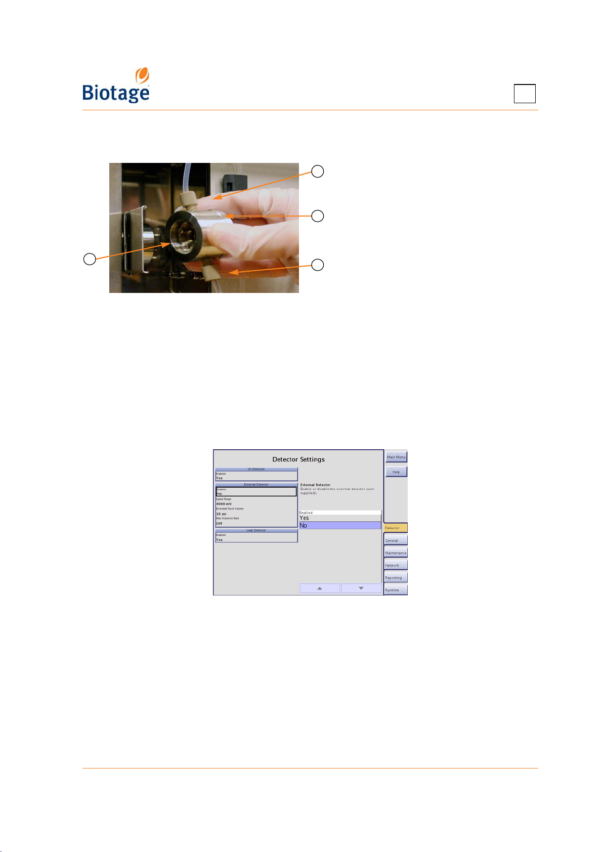
3
6. Select the Extended Flush Volume text box and enter the amount of solvent that has to be
added to the flushes due to the flow cell volume and/or the extra tubing associated with the
external detector.
A
A Flow Cell Outlet Tube
B Flow Cell
B
C Flow Cell Inlet Tube
D Opened Retaining Latch
D
Figure 3-3. Internal Detector Flow
C
Cell (Isolera Prime, One, and Four
Shown)
7. Select the Max Dispense Rate text box and enter the maximum speed at which liquid can be
pushed into the tubing of the external detector during the dispense stroke. The valid range is
1 to 200 ml/min when using an Isolera Prime, Isolera One, or Isolera Four system and 50 to
500 ml/min when using an Isolera LS system. If this parameter is turned off, the system's
maximum dispense rate will be used (i.e. 200 ml/min or 500 ml/min).
3.2.3 Disable an External Detector
To disable the external detector:
1. Select the Detector tab in the right-hand panel.
2. Select the Enabled text box in the External Detector field and select No.
Figure 3-4. Detector Tab
3.2.4 Enable or Disable the Leak Detector
Biotage Leak Detector can be used for safe, unattended operation. The leak detector is standard on
Isolera LS and optional on Isolera Prime, Isolera One, and Isolera Four.
To enable Biotage Leak Detector:
1. For installation instructions, see the “Moving an Isolera System” section in the “Isolera
Installation and Safety” document (P/N 411828).
2. Select the Detector tab in the right-hand panel.
3. Select the Enabled text box in the Leak Detector field and select Yes.
411829-L, System Settings April 2012 Page 3-3
Page 40
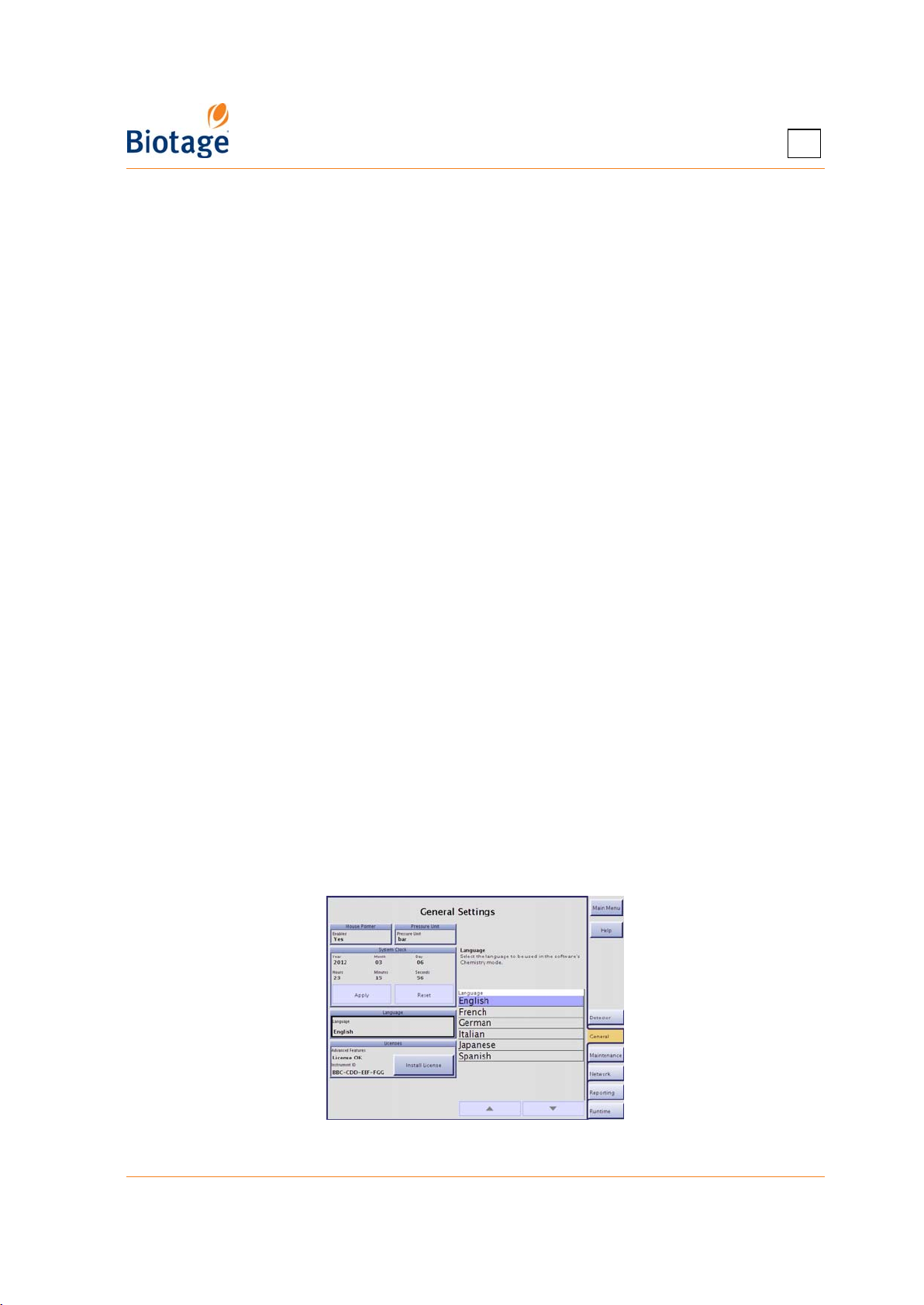
3
To disable Biotage Leak Detector:
1. Select the Detector tab in the right-hand panel.
2. Select the Enabled text box in the Leak Detector field and select No.
3.3 Change General Settings
3.3.1 Set the Date and Time
Setting the date and time correctly ensures an accurate date and time stamp for your result records
and can help you search for specific records.
1. Select the General tab in the right-hand panel.
2. Edit the date and time settings in the System Clock field by selecting the corresponding text box.
3. To apply your new settings, press Apply.
4. For the settings to take effect, restart the system:
a. Press Main Menu.
b. Press Shut Down.
c. When the message It is now safe to turn off the system appears on the screen, turn off
the system. The power switch is located underneath the touch screen.
d. Turn on the system.
3.3.2 Enable or Disable Mouse Pointer
When connecting a mouse to the MOUSE or USB port at the rear of the system, you need to enable
the mouse pointer.
1. Select the General tab in the right-hand panel.
2. To enable or disable the mouse pointer, select the Enabled text box in the Mouse Pointer field
and select Yes or No.
3.3.3 Set the Pressure Unit
1. Select the General tab in the right-hand panel.
2. Select the Pressure Unit text box and select the unit to be used by the system, bar or psi.
3.3.4 Set the Language Used in the Chemistry Mode
1. Select the General tab in the right-hand panel.
2. Select the Language text box and select the language to be used in the software’s Chemistry mode.
Figure 3-5. General Tab
411829-L, System Settings April 2012 Page 3-4
Page 41

3
3.3.5 Enable the λ-All Detection Mode and TLC to Step Gradient Editor
To enable the λ-all detection mode and the TLC to Step Gradient editor, you need a Spektra license.
To purchase a Spektra license, please contact your local representative. Note that the license is not
available for Isolera Prime systems.
To install a Spektra license for the λ-all detection mode and the TLC to Step Gradient editor:
1. Save the Spektra license file in a “biotage/isolera/” directory on a USB memory device.
2. Connect the memory device to the USB port located underneath the touch screen.
3. Select the General tab in the right-hand panel.
4. Press Install License in the Licenses field.
5. If the license is valid, License OK appears in the Advanced Features text box.
6. Remove the USB memory device.
7. Restart the system:
a. Press Main Menu and then Shut Down.
b. When the message It is now safe to turn off the system appears on the screen, turn off
the system. The power switch is located underneath the touch screen.
c. Turn on the system.
3.4 Configure a Network Connection
With your system connected to the network, it is possible to:
• Print purification reports to a network printer with postscript support; see “Set Up a Printer and
Auto Print of Reports” on page 3-6.
• Receive a report by e-mail when a purification has been completed; see “Set Up Auto Send of
Reports” on page 3-8.
• Receive an e-mail when user interaction is required during a purification, e.g. when the system
run out of empty collection vessels.
• Make your reports and methods available to other users by saving them in a share folder on
your network; see “Set Up File Sharing and Auto Save of Reports” on page 3-7.
• Back up your database and save the system configuration and logs in a share folder on your
network; see “Back Up and Restore the System’s Database” and “Export the System
Configuration and Logs” on page 3-12.
With the system connected to your network, it is also possible to perform the following tasks
through a standard web browser (through the Isolera Remote Viewer feature):
• Create a new method. If desired, the method can be based on a previous purification found
in the Results view.
• Check the status of the system and the progress of a purification.
• Instruct the system to start and stop collecting fractions by clicking the Collect All button
( = fractions are collected).*
• Instruct the system to switch to a new collection vessel by clicking the New Fraction button.*
• Instruct the system to start and end an isocratic segment by clicking the Hold button
( = isocratic hold is enabled).*
• Instruct the system to pause the purification in progress by clicking the Pause button. For
safety reasons, it is only possible to pause and not resume a run from your office.*
• Instruct the system to set the current UV level to 0 (zero) AU by clicking the UV Zero
button.*
• View, print, and export purification results.
* You must be logged in as the user defined in the purification run.
411829-L, System Settings April 2012 Page 3-5
Page 42
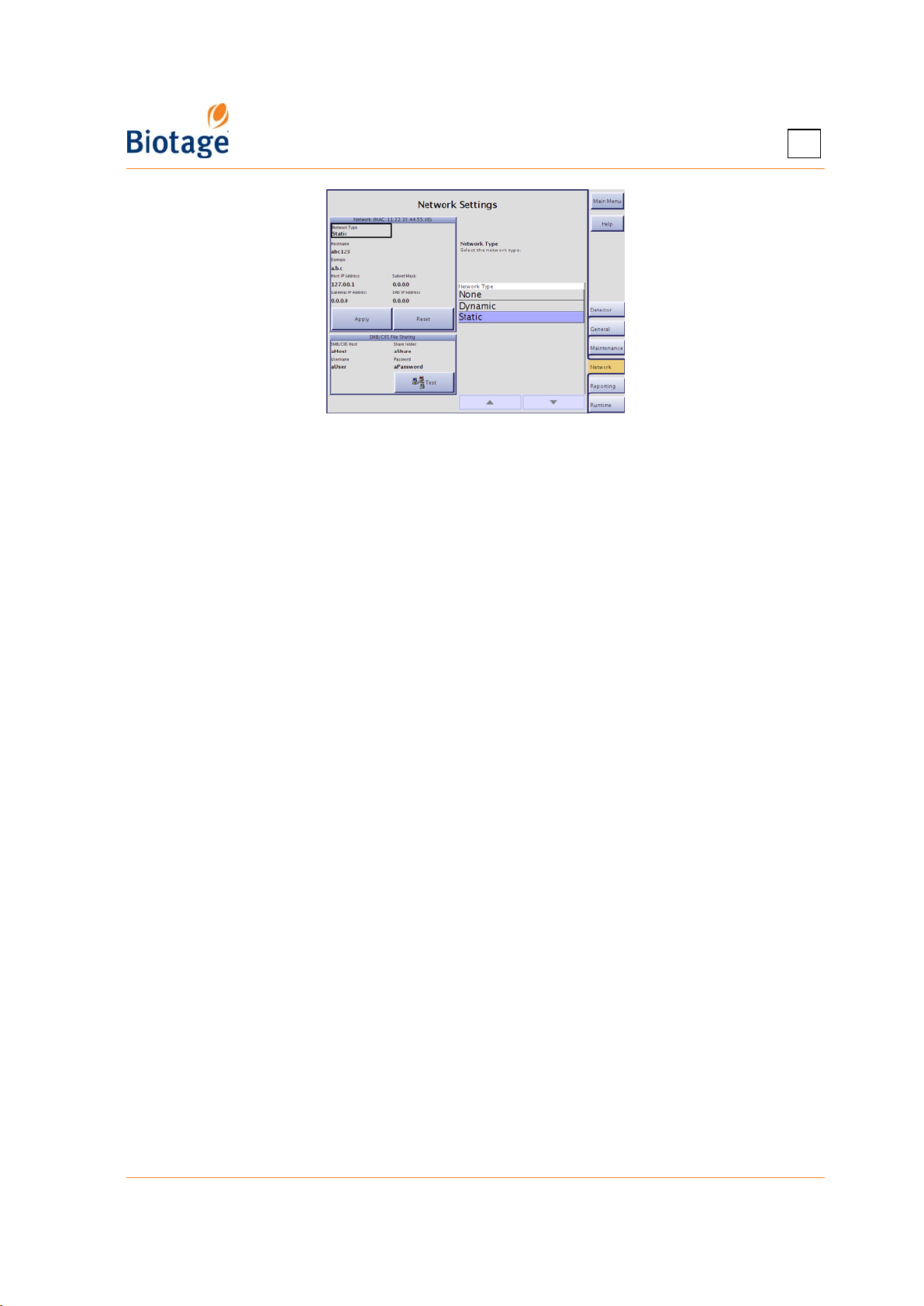
Figure 3-6. Network Tab
To configure the network connection:
1. Connect a shielded category 5 TP cable to the ETHERNET port.
2. Select the Network tab in the right-hand panel.
3. Select the Network Type text box and select Dynamic or Static.
4. Edit the network settings in the Network field. For more information, contact your IT
administrator. (To reset changes that have not been applied, press Reset.)
5. To apply your new settings, press Apply.
6. For the network configurations to take effect, restart the system:
a. Press Main Menu and then Shut Down.
b. When the message It is now safe to turn off the system appears on the screen, turn off
the system. The power switch is located underneath the touch screen.
c. Turn on the system.
3
To access the Isolera Remote Viewer:
1. Enter the URL http://MACHINENAME in a web browser (where MACHINENAME is the hostname
or the host IP address entered in the Network field above). Tip! You can also find the
hostname and host IP address in the About dialog at the main menu.
2. Press ENTER and the Isolera Remote Viewer web page is loaded. The page is automatically
updated every five seconds.
3.5 Change Report Settings
3.5.1 Set Up a Printer and Auto Print of Reports
If you want reports to be automatically printed when a purification has been completed, select the
Auto Print Reports text box at the Reporting tab and select Yes.
NOTE
If connecting a network printer, only printers with postscript
support can be used with the system.
To connect a USB printer to the system:
1. Connect your printer to the USB port at the rear of the system.
2. Turn the printer on.
3. Select the Reporting tab in the right-hand panel.
4. Select the Printer Type text box and select Local.
411829-L, System Settings April 2012 Page 3-6
Page 43
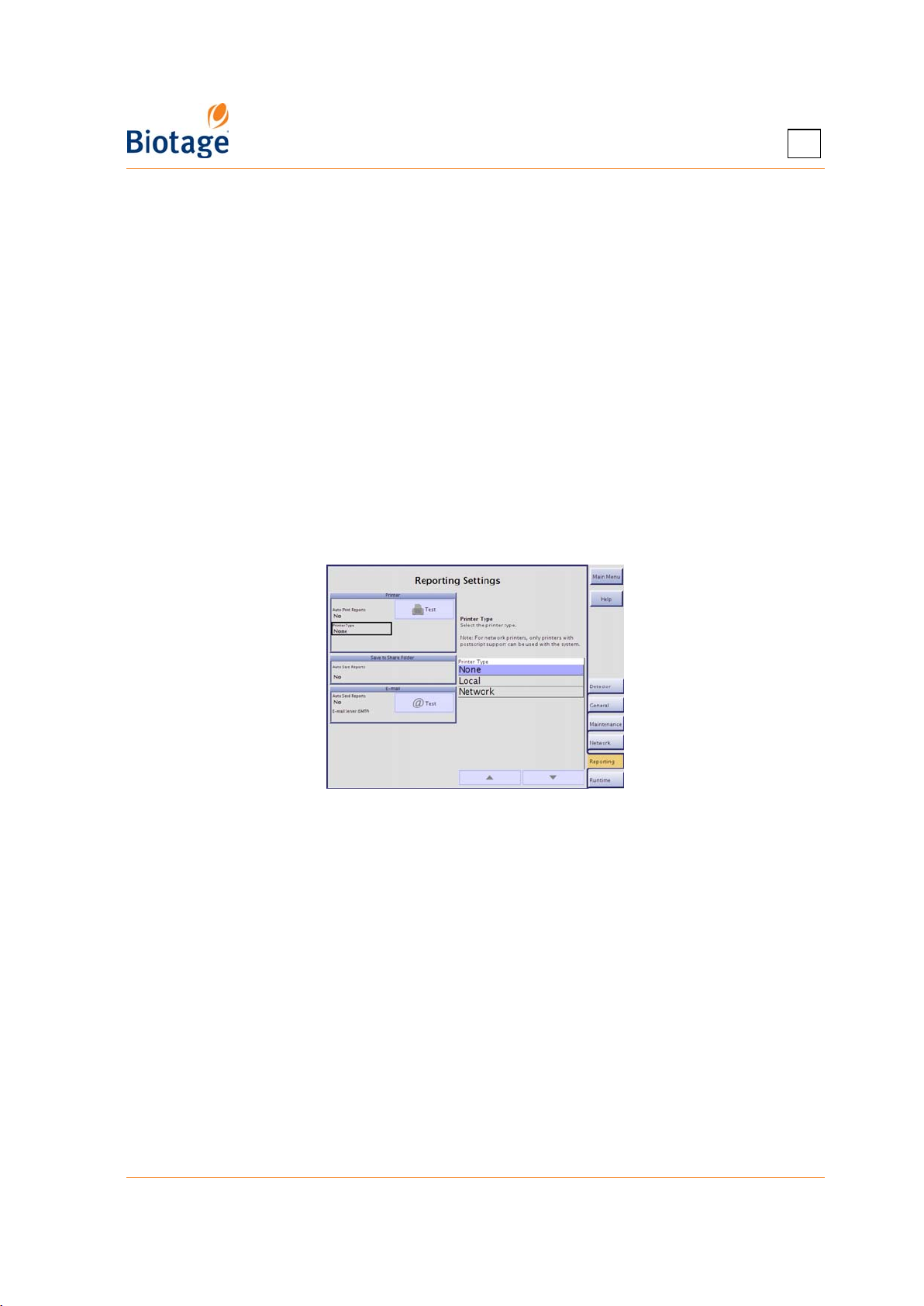
3
5. Select the Printer Model text box. The Printer Setup Wizard opens.
6. Read and follow the instructions that appear on the screen. Tip! If the Isolera system does not
have a matching printer driver for the connected printer, select Generic in the wizard’s
manufacturer list and check if there is a printer protocol available that is supported by your
printer (check the printer user manual).
7. When you have completed the printer setup using the wizard, select the Paper Size text box
and then select the desired paper format.
8. To test the connection, press Test in the Printer field. If a test page is printed, the connection
is working properly.
To connect a network printer with postscript support to the system:
1. Configure the network connection; see instructions on page 3-5.
2. Select the Reporting tab in the right-hand panel.
3. Select the Printer Type text box and select Network.
4. Enter the correct Network Printer Name and Network Printer Port by selecting the
corresponding text box. Contact your IT administrator for more information.
5. Select the Paper Size text box and then select the desired paper format.
6. To test the connection, press Test in the Printer field. If a test page is printed, the connection
is working properly.
Figure 3-7. Reporting Tab
3.5.2 Set Up File Sharing and Auto Save of Reports
If the Auto Save Reports option is enabled, a report is saved in a share folder on your network when
a purification has been completed. The report is saved as a PDF and/or a XML file (a text file
including all raw data).
1. Configure the network connection; see instructions on page 3-5.
2. Select the Network tab in the right-hand panel.
3. Enter the correct hostname, name of the share folder, user name, and password by selecting
the corresponding text box in the SMB/CIFS File Sharing field. Contact your IT administrator
for more information.
4. To test the connection, press Test in the SMB/CIFS File Sharing field.
5. If you want a report to be automatically saved in the specified share folder when a purification
has been completed:
a. Select the Reporting tab in the right-hand panel.
b. Select the Auto Save Reports text box and select the desired report format, PDF, XML
(text files including all raw data), or PDF and XML.
411829-L, System Settings April 2012 Page 3-7
Page 44
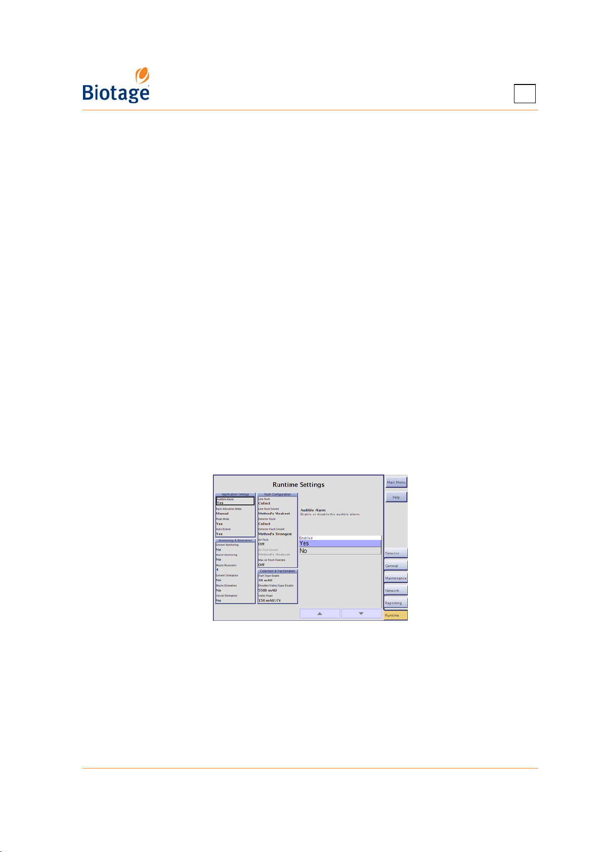
3
3.5.3 Set Up Auto Send of Reports
If the Auto Send Reports option is enabled, a report is sent to the e-mail address specified in the
user’s account when a purification has been completed. An e-mail will also be sent to the user when
user interaction is required, e.g. when a rack has to be replaced, a solvent needs to be replenished
(if monitoring is enabled), a waste reservoir needs to be emptied (if monitoring is enabled), and a
leak is detected (if using Biotage Leak Detector).
1. Configure the network connection; see instructions on page 3-5.
2. Select the Reporting tab in the right-hand panel.
3. Enter the outgoing e-mail server address by selecting the E-mail Server (SMTP) text box.
For more information, contact your IT administrator.
4. Select the Auto Send Reports text box and select Yes.
5. To test the connection, press Test in the E-mail field. The Test E-mail dialog opens.
6. Enter your e-mail address and press Send. If you receive a test message, the connection is
working properly.
3.6 Change Runtime Settings
3.6.1 Enable or Disable Audible Alarm
If the Audible Alarm option is enabled, an audible warning will sound in the following situations:
1) rack change is needed, 2) leakage (if using Biotage Leak Detector), 3) high pressure, 4) low
solvent volume (if solvent monitoring is enabled), 5) full waste reservoir (if waste monitoring is
enabled), 6) misalignment of the collection arm, 7) pump failure, 8) waste reservoir has to be
reconnected (when using the bypass tray function), and 9) the hold function has been active for
8 hours.
1. Select the Runtime tab in the right-hand panel.
2. To enable or disable the audible alarm, select the Audible Alarm text box and select Yes or No.
Figure 3-8. Runtime Tab (Isolera Four Shown)
3.6.2 Enable or Disable Automatic Rack Allocation
If automatic rack allocation is enabled, racks or vessels (depending on the selected method) are
automatically allocated one at a time as they are needed. The collection area must therefore at all
times be loaded with racks in all positions.
Two automatic rack allocation methods are available:
• Automatic: The system allocates racks in sequence, starting with rack A, then B, and so
forth. With this allocation method, the collection tray can be shared by several runs with the
same rack type but a single rack cannot be shared by several runs.
411829-L, System Settings April 2012 Page 3-8
Page 45
3
• Automatic Vessel: The system allocates vessels in sequence, starting with the first vessel
in rack A, the second in rack A, and so forth. With this rack allocation method, racks can be
shared by several runs but the collection tray cannot be shared by several users.
When enabling automatic rack allocation on an Isolera Four system, the following rules also apply:
• All racks on the collection tray must be of the same type. The rack type to be used is
decided by the first purification that is queued up.
• Allocation only when needed. No rack or vessel allocation is performed when a
purification is queued up. When the run is started racks or vessels are allocated one at a time
as they are needed.
• Always replace all racks when asked to. If the system runs out of vessels, you will be
asked to replace all racks in the collection area at the same time (even if some of the racks
have been used by previous runs).
To enable or disable automatic rack allocation:
1. Select the Runtime tab in the right-hand panel.
2. Select the Rack Allocation Mode text box.
3. To enable automatic rack allocation, select Automatic or Automatic Vessel.
4. To disable automatic rack allocation, select Manual.
3.6.3 Enable or Disable Peak Mode
If Peak Mode is enabled, all fractions of a peak will have the same color in the status view (the
Status tab in the Chemistry mode).
1. Select the Runtime tab in the right-hand panel.
2. To enable or disable Peak Mode in the status view, select the Peak Mode text box and select
Yes or No.
3.6.4 Enable or Disable Auto Extend
If Auto Extend is enabled and the system is collecting fractions and remaining light absorption is
detected when the system nears the end of a purification, the system enters the Auto-Extend
mode. This extends the gradient purification stage of the run with 25% of the total gradient length
using the final conditions in the method.
1. Select the Runtime tab in the right-hand panel.
2. To enable or disable Auto Extend, select the Auto Extend text box and select Yes or No.
3.6.5 Enable or Disable Monitoring of Reservoirs
If the Solvent Monitoring and Waste Monitoring options are enabled, the system will issue a warning
when it is time to replenish a solvent and empty a waste reservoir.
To enable solvent and/or waste monitoring:
1. Select the Runtime tab in the right-hand panel.
2. To track solvent levels, select the Solvent Monitoring text box and select the level when the
processing shall be paused and refill requested.
3. To track waste levels, select the Waste Monitoring text box and select the level when the
processing shall be paused and emptying requested.
4. If using an Isolera Four system, ensure to select the number of waste reservoirs to be used in
the Waste Reservoir text box. The waste can either be pooled into a single waste reservoir
(insert all four waste outlet tubes into a single waste reservoir) or collected in four waste
reservoirs (insert each waste outlet tube into a single waste reservoir).
5. If you want an audible alarm to sound when it is time to replenish a solvent or empty a waste
reservoir, check that the Audible Alarm option is enabled (see page 3-8).
411829-L, System Settings April 2012 Page 3-9
Page 46
3
6. In the Chemistry mode, enter the capacities and current fluid levels for the solvent and/or
waste reservoirs; see “Set the Reservoir Volumes” on page 4-32. (For the system to be able to
maintain a running calculation of fluid levels in each reservoir, the capacities and current fluid
levels for the reservoirs must be entered each time you empty a waste reservoir or replenish a
solvent.)
To disable solvent and/or waste monitoring:
1. Select the Runtime tab in the right-hand panel.
2. Select the Solvent Monitoring and/or Waste Monitoring text box and select No.
3.6.6 Enable or Disable Run Requirement Estimation
If you enable vessel, solvent, and waste estimation, you will be informed (when allocating the
cartridge and rack positions) if a sufficient quantity of vessels is allocated, if a sufficient quantity of
the correct solvent is present in each solvent reservoir, and if the waste reservoir has sufficient
capacity for the run.
To enable or disable vessel, solvent, and/or waste estimation, select the corresponding text box and
select Yes or No. If using an Isolera Four system, ensure to select the number of waste reservoirs
to be used in the Waste Reservoir text box. The waste can either be pooled into a single waste
reservoir (insert all four waste outlet tubes into a single waste reservoir) or collected in four waste
reservoirs (insert each waste outlet tube into a single waste reservoir).
3.6.7 Specify How Flushes Are Performed
At the end of a purification, i.e. after the gradient purification stage is completed, the system
performs a:
• Line Flush: The system flushes the inlet line and the cartridge with 9 ml (when using an
Isolera Prime, Isolera One, or Isolera Four system) or 20 ml (when using an Isolera LS
system) of the specified solvent or solvent mix.
• Air Flush: The system flushes the inlet line and the cartridge with air and a small amount of
the specified solvent or solvent mix. The flush volume depends on the cartridge type.
Air Flush is optional. This feature is not available with Isolera Prime.
• Detector Flush: The system flushes the detector with 27 ml (when using an Isolera Prime,
Isolera One, or Isolera Four system) or 45 ml (when using an Isolera LS system) of the
specified solvent or solvent mix.
To change the flush settings:
1. Select the Runtime tab in the right-hand panel.
2. To enable or disable the line flush, select the Line Flush text box and select Collect (the line
flush will be collected on the collection tray), To Waste (the line flush will be sent to waste), or
Off (no line flush will be performed).
3. To enable or disable the detector flush, select the Detector Flush text box and select Collect
(the detector flush will be collected on the collection tray), To Waste (the detector flush will be
sent to waste), or Off (no detector flush will be performed).
NOTE
If the automatic line flush is disabled, ensure to prime the cartridge flow
path before each run.
We recommend that the detector flush is kept enabled. A dirty detector
flow cell has decreased transmissivity, which causes increased noise level,
decreased response, and difficulties performing UV Zero.
411829-L, System Settings April 2012 Page 3-10
Page 47

3
4. To enable or disable air flush, select the Air Flush text box and select To Waste or Off. This
feature is not available with Isolera Prime.
5. To change the solvent or solvent mix to be used for the line, detector, and/or air flush, select
the corresponding text box and select the desired solvent or solvent mix:
• Method
• System – The system will flush with the weakest or strongest solvent mounted on the system.
• Gradient – The system will flush with the solvent mix used in the start or the end of the
gradient. (Not available for air flush.)
• Channel x
3, or 4); see “Assign Solvents to the Solvent Inlets” on page 4-32. Note that Isolera One,
Four, and LS have four solvent inlets while Isolera Prime has two.
–
The system will flush with the weakest or strongest solvent used in the run.
–
The system will flush with the solvent mounted on the specified channel (1, 2,
3.6.8 Configure Collection and Fractionation
Refer to the “Collection and Fractionation” appendix on page A-1 for details.
1. Select the Runtime tab in the right-hand panel.
2. Select the Start Slope Enable text box and enter the value when start slope is enabled.
3. Select the Shoulder/Valley Slope Disable text box and enter the level when shoulder and
valley fractionation is disabled.
4. Select the Valley Slope text box and enter the level when valley fractionation occurs.
3.7 Maintenance
3.7.1 Export the System Configuration and Logs
If requested by 1-Point Support™ to send in your system’s log files, follow the instructions below.
The system configuration and logs can be saved on a USB memory device connected to the USB
port at the front of the system or in a share folder on your network (if file share has been set up;
see page 3-7).
1. Select the Maintenance tab in the right-hand panel.
2. If you want to save the system configuration and logs on a USB memory device:
a. Connect the memory device to the USB port located underneath the touch screen.
b. Press Export in the System Configuration and Logs field.
3. If you want to save the system configuration and logs in the specified share folder, press
Export in the System Configuration and Logs field.
4. The system configuration and logs are saved as a zip file at \biotage\isolera\logs\. Send the zip
file to 1-Point Support; see “Contact Information” on page 7-1.
3.7.2 Restore the System Configuration
The system configuration contains all the settings available in the System mode except for the
internal detector calibration (which is stored on the detector), the local printer (if connected), and
the date and time.
NOTE
Only restore the system configuration when instructed to do so by Biotage.
Do not restore the system configuration on your Isolera system using a
system configuration for another Isolera system.
If you have problem with the restore, please contact 1-Point Support.
411829-L, System Settings April 2012 Page 3-11
Page 48

3
To restore the system configuration e.g. after an update of the system's operating system:
1. Select the Maintenance tab in the right-hand panel.
2. Connect the USB memory device containing the zip file with the desired system configuration to
the USB port located underneath the touch screen. Note that the zip file must be saved at
\biotage\isolera\logs\ on the USB memory device.
3. Press Restore Configuration in the System Configuration and Logs field.
4. In the Select Zip File dialog, select the zip file and press OK. The Restore from USB Device
dialog opens.
5. To confirm restore, press Restore.
6. When the Restore Successful dialog appears, press OK. The Restart Required dialog opens.
7. Read the instructions in the dialog on how to restart the system and then press OK.
8. Restart the system.
9. If you have a USB printer connected to the system, set up the printer as described in “Set Up a
Printer and Auto Print of Reports” on page 3-6.
10. Verify that the calibration of the touch screen and the fraction collector is working properly. If
the system needs to be recalibrated; see “Calibrate the Touch Screen” on page 3-12 and
“Calibrate the Fraction Collector” on page 3-13.
3.7.3 Back Up and Restore the System’s Database
To back up the database:
1. Select the Maintenance tab in the right-hand panel.
2. If you want to save the backup on a USB memory device:
a. Connect a memory device to the USB port located underneath the touch screen.
b. Press Back Up in the Back Up and Restore Database field.
3. If you want to save the backup in the specified share folder, press Back Up in the Back Up
and Restore Database field. The backup file is saved at \biotage\isolera\backup\.
To restore the database:
1. Select the Maintenance tab in the right-hand panel.
2. If the backup file you want to use to restore the database is saved on a USB memory device
(at \biotage\isolera\backup\):
a. Connect the memory device to the USB port located underneath the touch screen.
b. Press Restore in the Back Up and Restore Database field.
3. If the backup is available in the specified share folder (at \biotage\isolera\backup\), press
Restore in the Back Up and Restore Database field.
4. In the Select Backup File dialog, select the backup file and press OK. The Restore from USB
Device/Share Folder dialog opens.
5. To confirm restore, press Restore.
3.7.4 Calibrate the Touch Screen
If the touch screen needs to be recalibrated, use the following procedure.
1. Select the Maintenance tab in the right-hand panel.
2. Press Calibrate in the Touch Screen field. Read and follow the instructions that appear on the screen.
411829-L, System Settings April 2012 Page 3-12
Page 49
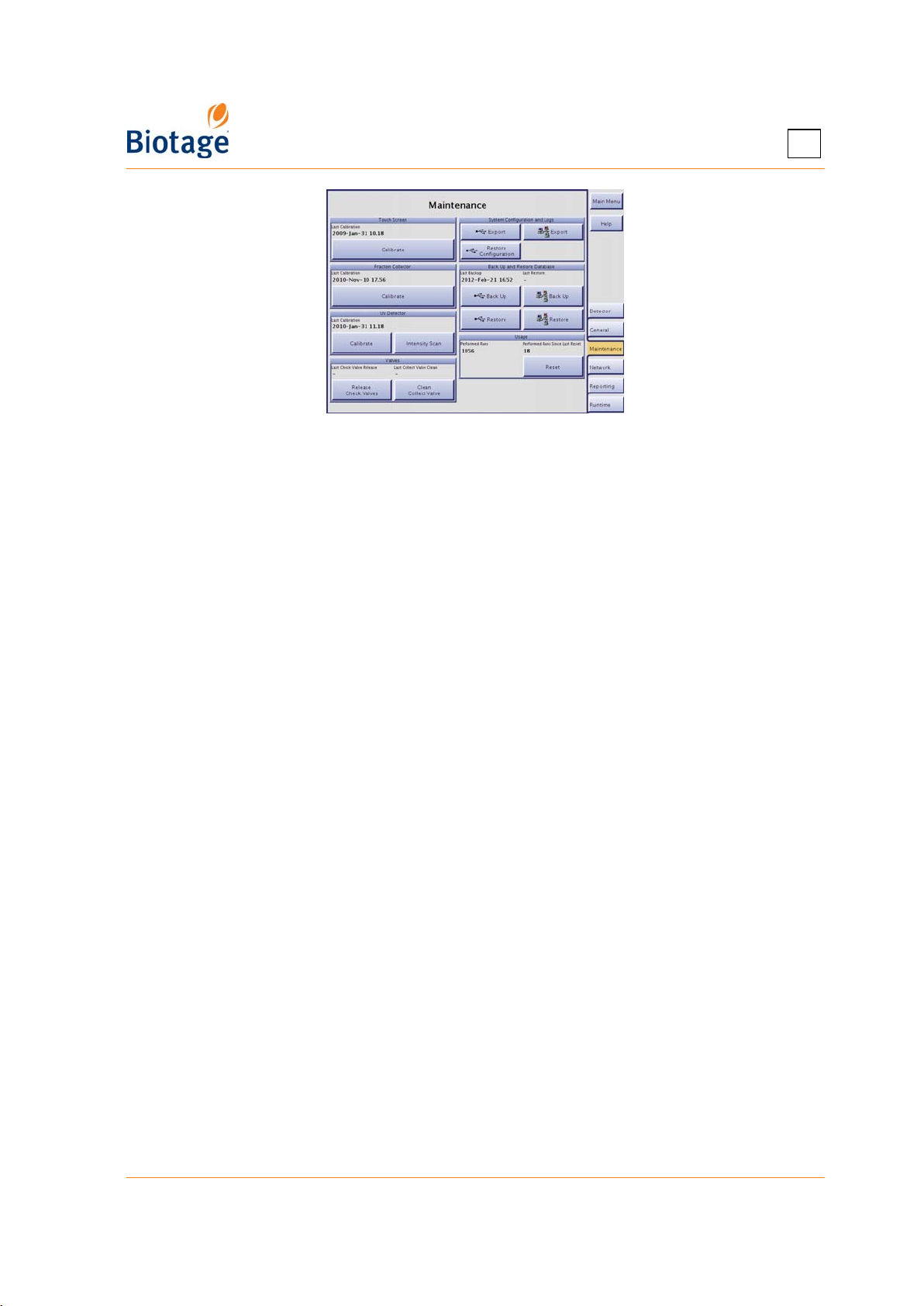
3
Figure 3-9. Maintenance Tab
3.7.5 Calibrate the Fraction Collector
If the fraction collector needs to be recalibrated, use the following procedure.
1. Select the Maintenance tab in the right-hand panel.
2. Press Calibrate in the Fraction Collector field. Read and follow the instructions that appear
on the screen.
3.7.6 Calibrate the Internal Detector
If the internal detector needs to be recalibrated (e.g. when a new detector lamp or flow cell has
been installed), use the following procedure.
NOTE
Only perform an intensity and absorbance calibration when you have
installed a new detector lamp. If you have installed a new detector flow
cell, perform an absorbance calibration. (The type of calibration is selected
in the wizard.)
1. Select the Maintenance tab in the right-hand panel.
2. Press Calibrate in the UV Detector field. Read and follow the instructions that appear on the
screen.
3.7.7 Perform an Intensity Scan of the Internal Detector
If requested by 1-Point Support to perform an intensity scan, follow the instructions below.
1. Select the Maintenance tab in the right-hand panel.
2. Press Intensity Scan in the UV Detector field. Read and follow the instructions that appear on the
screen. When the intensity scan has been completed successfully, the data is saved in a system log.
3. Export all system logs as described on page 3-11.
4. Send the system logs to 1-Point Support; see “Contact Information” on page 7-1.
3.7.8 Clean the Collect Valve
Dripping needle and/or inconsistent dispensing volumes can be signs of a dirty collect valve. Use
the following procedure to clean the collect valve.
1. Select the Maintenance tab in the right-hand panel.
2. Press Clean Collect Valve in the Valves field. Read and follow the instructions that appear on
the screen.
411829-L, System Settings April 2012 Page 3-13
Page 50
3
3.7.9 Release Stuck Check Valves
Low or inconsistent flow delivery volume and/or superimposed periodic UV or UV-VIS signals can be
signs of sticking check valves. Use the following procedure to release stuck check valves.
1. Select the Maintenance tab in the right-hand panel.
2. Press Release Check Valves in the Valves field. Read and follow the instructions that appear
on the screen.
3.7.10 View and Reset the Usage Statistics
Both the number of runs performed on the system since it was installed and the number of runs
performed since the last reset are displayed in the Usage field at the Maintenance tab.
To reset the usage statistics:
1. Select the Maintenance tab in the right-hand panel.
2. Press Reset in the Usage field. The Reset Performed Runs dialog opens.
3. To confirm reset, press Yes.
411829-L, System Settings April 2012 Page 3-14
Page 51

Chapter
Operation
(Chemistry Mode)
4
WARNING
Before performing any procedures in this chapter, please read and observe
the safety requirements in the “Isolera Installation and Safety” document
(P/N 411828). Failure to follow those requirements may result in personal
injury and/or equipment damage.
4.1 Start Up the System
It is recommended that you start up the system in the following order:
1. Ensure that all liquid lines are connected correctly and securely; see Figure 4-10 on page 4-16.
WARNING
To avoid being struck by the collection arm, keep your hands out of range
of the collection arm while the homing routine runs in step 2 below.
2. Turn on the system. The power switch is located underneath the touch screen. The collection
arm moves through its homing routine and the system boots to the system’s main menu.
3. To set up, control, monitor, and review a purification, press Chemistry. The system is opened
in the Chemistry mode.
If you want to administrate cartridge types, methods, rack types, results, solvents, and user
accounts, see “Log into the Data Administration Mode” on page 2-1.
If you want to change detector, network, reporting, and runtime settings, set the system clock, set
the language used in the Chemistry mode, enable the λ-all detection mode and the TLC to Step
Gradient editor (requires a Spektra license), calibrate the touch screen, fraction collector, and
internal detector, perform an intensity scan of the internal detector, release stuck check valves,
clean the collect valve, back up and restore the database, export the system configuration and logs,
restore the system configuration, view and reset usage statistics, etc, see “Log into the System
Mode” on page 3-1.
For more information about the software modes, see “Software Description” on page 1-7.
4.2 Shut Down the System
WARNING
Failure to perform an orderly system shutdown may result in user data
corruption. If possible, avoid shutting down during a purification.
Use the following procedure to perform an orderly system shutdown:
1. If you are not at the main menu, press Main Menu in the right-hand panel.
2. Press Shut Down.
3. When the message It is now safe to turn off the system appears on the screen, turn off the
system. The power switch is located underneath the touch screen.
4. If desired, unplug the power cord from the power outlet.
411829-L, Operation April 2012 Page 4-1
Page 52

4
4.3 Control the UV Lamp
The internal detector uses an ultraviolet (UV) lamp and, if using the UV-VIS detector, a tungsten lamp in
its detection process. The UV lamp must be warmed up in order for the signal to be accurate and stable.
NOTE
The UV lamp should be turned on 7.5 minutes before starting a purification
so the UV lamp can reach operating temperature.
The lamp(s) is/are automatically turned on when:
• The Isolera system is switched on.
• The user enters the Chemistry mode (i.e. press the Chemistry button in the main menu).
• The user starts a run (i.e. press the button in the Run Parameters dialog). However, before
starting the run, the software waits (approximately 7.5 minutes) for the UV lamp to warm up.
You can also turn on the detector lamp(s) manually by pressing Turn Lamp On in the right-hand
panel. By doing this ahead of time, you can avoid the delay that is required if the software turns the
lamp(s) on at the start of a run.
To prolong lamp life, the lamp(s) is/are turned off automatically if the system is idle (no purification
is started and no user interaction is detected) for approximately two hours.
Bypass the Automatic UV Lamp Warm-up Period
You can bypass the automatic UV lamp warm-up period by pressing Skip Warm Up in the right-
hand panel. However, if the UV lamp has not reached operating temperature, purification results
may not be optimal.
4.4 Create, Open, and Edit Methods
4.4.1 Create or Open a Method
NOTE
If you want to use the method wizard, see page 4-13. The wizard will
guide you step-by-step through the setup of a purification with a gradient
including up to three steps using two solvents.
To scroll a list down or up, press or .
1. To create a new method:
a. Select the Method tab in the right-hand panel and press New....
b. If the system is configured to use default methods (see “Set Default Methods” on page 2-4),
the New Method dialog opens. Select the default method that you want to base your method
on and press OK. (If there is only one default method, it will be opened when you press New.)
2. To open and edit an existing method:
a. Select the Method tab in the right-hand panel and press Open....
b. If the method is stored in the system’s database, select the owner of the method in the
Open Method dialog. All methods of the selected user are listed. To select one of the
preconfigured Biotage methods, select the user “Biotage Methods”.
c. If the method is stored on a USB memory device, connect the device to the USB port
located underneath the touch screen and press in the Open Method dialog.
d. If the method is stored in the share folder on your network, press in the Open Method
dialog.
e. Select the method and press OK.
411829-L, Operation April 2012 Page 4-2
Page 53
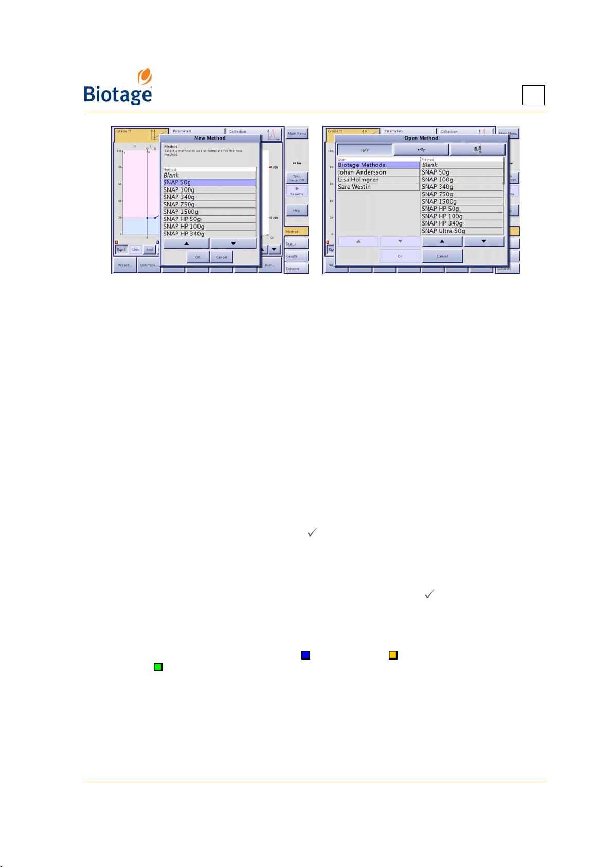
Figure 4-1. New Method and Open Method Dialogs (Isolera LS Shown)
3. To create a method from a previous purification:
a. Select the Results tab in the right-hand panel.
b. Select the run at the Result Selection tab and press Create. For information on how to
find the desired run, see “Search for Records” on page 4-28. The method is opened at the
Method tab and can be edited and/or saved. If desired, the system can help you to
optimize the gradient to isolate one of the peaks and reduce the amount of solvent used.
For instructions, see “Create a Gradient at the Gradient Tab” on page 4-3.
4
Create a Gradient at the Gradient Tab
NOTE
If you want to calculate the gradient from TLC data, see page 4-10.
Isolera One, Four, and LS have four solvent inlets (A, B, C, and D) while
Isolera Prime has two (A and B).
1. Select the Gradient tab.
2. The gradient can be set up using the gradient table and/or the gradient graph. To show or hide
the gradient table, press the Table button ( = gradient table is shown).
3. In the graph, the X-axis indicates the length and the Y-axis indicates the percentage of Solvent B
(if a blue gradient line), Solvent C (if a yellow gradient line), or Solvent D (if a green gradient
line) in the solvent mix. To change the length unit, press the Unit button repeatedly until the
desired unit appears; CV (Column Volumes), milliliter, or minutes. CV is the default unit.
4. If you want to equilibrate the cartridge before the run, press Equil. ( = equilibration is
enabled). The default equilibration length is 3 CV (3 to 5 CV are recommended for full
equilibration).
5. To add a gradient segment, select a segment in the gradient table or the graph (see Figure 4-2)
and press Add. The new segment will be added after the selected segment.
6. To add a gradient segment with Solvent B ( ) and Solvent C ( ) and/or with Solvent C and
Solvent D ( ), press B/C and/or C/D. The new segment will be added at the end of the gradient.
7. To delete a gradient segment, select it in the gradient table or the graph (see Figure 4-2) and
press Delete.
411829-L, Operation April 2012 Page 4-3
Page 54
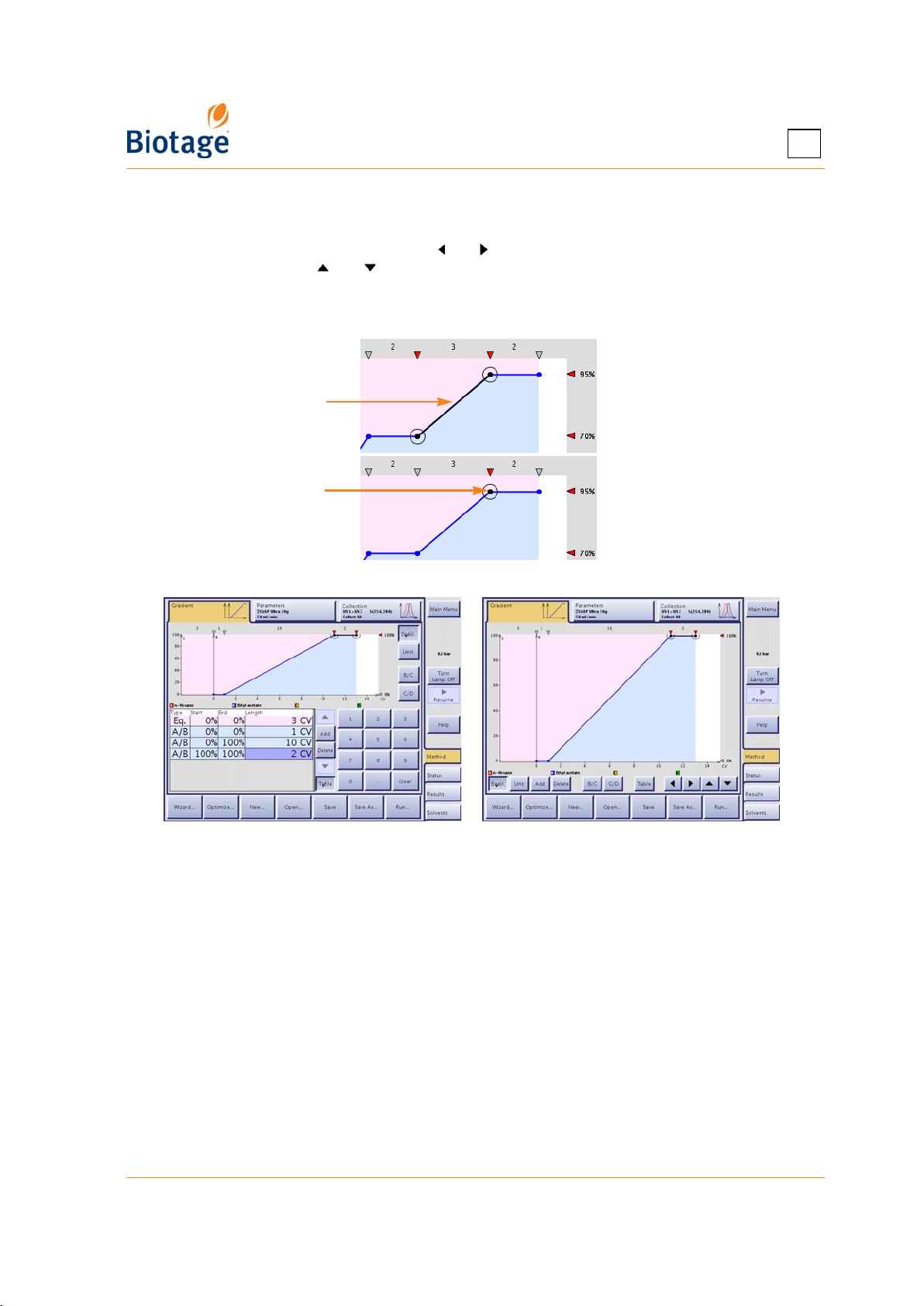
8. To increase or decrease the length of a gradient segment or change the solvent mix:
• Using the gradient graph: Drag the segment or node to the desired position (with 0.5 CV
and 5% resolution). To fine tune (with 0.1 CV and 1% resolution), select a segment or
node (see Figure 4-2) and use the and buttons to increase or decrease the length of a
segment and the and buttons to increase or decrease the solvent percentage. The
fine tuning buttons are only available when the gradient table is not shown.
• Using the gradient table: Select the value you want to change and enter the desired value
using the keypad.
Selected segment
Selected node
Figure 4-2. Selected Gradient Segment and Node
4
Figure 4-3. Gradient Tab With and Without Gradient Table
(System With Four Solvent Inlets Shown)
Specify the Method Parameters at the Parameters Tab
1. Select the Parameters tab.
2. Select the User text box and select your user name. If you have not been assigned a user
name, please contact your system supervisor.
3. Select the Cartridge Type text box and select the cartridge type to be used. If you do not want
to use the default flow rate and/or equilibration flow rate for the cartridge type, select the
corresponding text box and enter the desired flow rate. See Table 4-3 on page 4-21 for
recommended flow rates. The maximum flow rate that can be used depends on:
• the maximum fill rate(s) defined for the used solvent(s) in the Data Administration mode,
and
• the maximum dispense rate of the system (200 ml/min for Isolera Prime, One and Four,
and 500 ml/min for Isolera LS) or, if using an external detector, the maximum dispense
rate defined for the external detector in the System mode.
411829-L, Operation April 2012 Page 4-4
Page 55
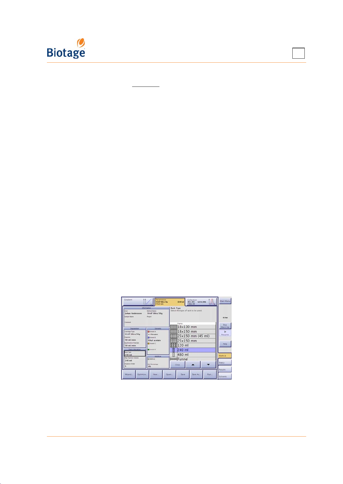
4
As a single-piston pump only delivers liquid during the dispense stroke, the maximum flow rate
when using an Isolera Prime system is equal to (Max Fill Rate x Max Dispense Rate)/(Max Fill
Rate + Max Dispense Rate).
80 ml/min and you use a external detector with the maximum dispense rate of 100 ml/min, the
highest flow rate that can be used is (50x100)/(50+100)=33 ml/min. If the external detector is
disabled, the highest flow rate that can be used is (50x200)/(50+200)=40 ml/min.
If small test tubes are to be used, ensure to adjust the flow rate so that no
splashing will occur when fractions are collected.
4. Select the Rack Type text box and select the rack type to be used; see Table 4-1 on page 4-7
for guidance. If you do not want to use the default max fraction volume for the vessel type
and/or the default dispensation order (S-pattern), select the corresponding text box and
change the setting. The software prevents you from entering a fraction volume that will
overflow the vessels.
5. Select the solvents to be used by selecting the corresponding text box in the Solvents field.
(They should be the solvents determined by the TLC procedure.) To show all solvents, press
Show All. To only show the solvents connected to the system, press Show Connected. Note
that the solvent percentages are specified at the Gradient tab.
For reversed-phase purification with methanol and water, it is strongly
recommended to premix the water with 5% of methanol and degass either
through vacuum or sonication. Degassing of protic solvent blends
decreases out-gassing of entrapped air during gradient elution, which will
impact gradient performance and flow rates.
Examples: If the fill rates for the used solvents are 50 ml/min and
WARNING
NOTE
If automatic rack allocation is enabled, all racks on the collection tray must
be of the same type. When using an Isolera Four system, the rack type to
be used is decided by the first purification that is queued up. Any
purification queued up after that must use the same rack type. To change
rack type, wait until all present runs are finished and then remove them at
the Status tab.
Figure 4-4. Parameters Tab (Isolera LS Shown)
411829-L, Operation April 2012 Page 4-5
Page 56

4
Optional Method Parameters
• Method Name: If you want to save the method, select the Method Name text box and enter a
method name. If you are editing an existing method and save it under a new name, the original
method remains unaltered under its original name.
• Sample Name: If left blank, the sample name will be auto-generated when the purification is
performed. To enter a sample name, select the Sample Name text box.
• Project: If you want the method to be associated with a project, select the Project text box
and select or create the project.
• Comment: If you want to enter a comment, select the Comment text box.
• Additive: If you want to use a fixed percentage of additive during the purification, select the
additive to be used (by selecting the Additive text box) and the percentage of the additive in
the solvent mix (by selecting the Mix Percentage text box. Not available with Isolera Prime.
Rack Selection
Based on 13 CV gradient in Collect All mode (with slope and valley fractionation disabled), the
following apply in the rack selection table on page 4-7:
Requires one (1) rack of this type.
Requires multiple racks of this type, but no rack change during the run. See the number of
racks required in the table.
Rack change required during the run. See the number of racks required in the table.
Not recommended.
Note that:
• Isolera Prime can only be used with one collection tray.
• The maximum collection volume for Isolera LS can be increased from 9.6 liters up to 320 liters
by using a funnel rack kit from Biotage. The funnel rack kit comes with two racks (16 positions
each) and a cart with wheels that holds the Isolera LS system and the collection vessels. For
more information, please contact your local representative.
411829-L, Operation April 2012 Page 4-6
Page 57
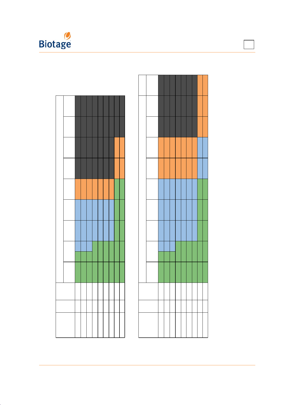
4
#
(1980)
1500g
§
75L
(1056)
§
(990)
750g
§
75M
(528)
340g
(510/582)
§
75S
(264)
100g
Cartridge Type (CV in ml**)
(132/164)
System with One Collection Tray
50g
(66/85)
2/2 3/3 5
§
75L
(1056)
§
(990)
750g
§
75M
(528)
¶
340g
(510/582)
75S
(264)
100g
Cartridge Type (CV in ml**)
(132/164)
50g
System with Two Collection Trays
(66/85)
2/2 3/3 5 9/10 9
2/2 2 3 3 6
Table 4-1: Rack Selection Table
25g*
(33/45)
10g*
(15/17)
(ml)
Volume
per Tray
per
Tray
Racks
Rack Type
4 432 x 4 2 2/3 4/5 8
4 490 x 4 2 2/3 4/5 7
4 504 x 4 2 2/3 4/5 7
†
†
†
13x100 mm
16x100 mm
18x130 mm
‡
795 x 4
4 770 x 4 2/2 3/3 5
†
16x150 mm
18x150 mm 4 756 x 4 2/2 3/3 5
25x150 mm 4
120 ml 4 720 x 4 2/2 3/3 5
240 ml 1 4320 2/2 2
480 ml 1 4800 2/2 2
411829-L, Operation April 2012 Page 4-7
25g*
(33/45)
10g*
(15/17)
(ml)
Volume
per Tray
per
Tray
Racks
Rack Type
4 432 x 4 2 2/3 4/5 8 16/18 16
4 490 x 4 2 2/3 4/5 7 14/16 15
4 504 x 4 2 2/3 4/5 7 14/15 14
†
†
†
16x100 mm
18x130 mm
13x100 mm
‡
795 x 4
4 770 x 4 2/2 3/3 5 9/10 9
†
16x150 mm
18x150 mm 4 756 x 4 2/2 3/3 5 9/10 10
25x150 mm 4
120 ml 4 720 x 4 2/2 3/3 5 10/11 10
240 ml 1 4320 2/2 2 3 4 6
*
Cannot be used on Isolera LS.† Not recommended for use on Isolera LS.‡ When using 53-ml test tubes.
480 ml 1 4800
Not available with Isolera Prime. Two collection trays can be used if the system is upgraded to Isolera One or Four.
§
¶
#
**
When two column volumes are listed, the first is for SNAP and the second is for SNAP Ultra.
Not recommended for use on Isolera Prime, Isolera One, or Isolera Four.
Not recommended for use on Isolera Prime.
Page 58
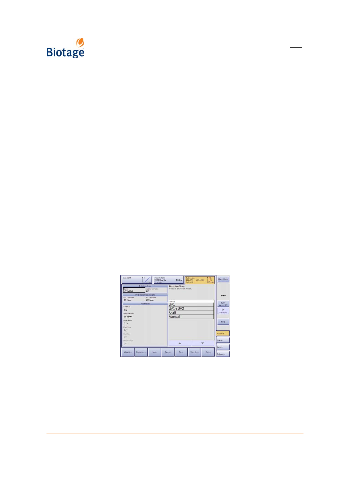
4
Specify Collection Parameters at the Collection Tab
1. Select the Collection tab.
2. Select the Source text box and select a detection mode:
• UV1+UV2: Control the collection and fractionation using both wavelength channels.
Possible collection and fractionation parameters are Collect All, Start Threshold, Slope,
Shoulder, and Valley. (Only available if you have the variable or the UV-VIS detector.)
• UV1: Control the collection and fractionation using one wavelength channel. (If you have
the variable or the UV-VIS detector, channel 2 is used for monitoring of the run.) Possible
collection and fractionation parameters are Collect All, Start Threshold, Slope, Shoulder,
and Valley.
• λ-all: The system uses average absorbance within a user-defined range for collection and
fractionation. Possible collection and fractionation parameters are Collect All, Start
Threshold, and Valley. (Only available on systems with a Spektra license installed.)
• Manual: Control the collection manually; enabling or disabling Collect All.
• External: Control the collection and fractionation using an external detector (e.g. an
Biotage ELSD-1080 detector). Possible collection and fractionation parameters are Collect
All and Start Threshold.
3. If you want the system to perform baseline correction, turn on the Baseline Correction
option. (Only available on systems with a Spektra license installed.)
If this option is turned on, the gradient run is preceded by a short solvent light absorbance
detection phase. During this phase, the light absorbance of the used solvents is measured at all
wavelengths that will be used for collection and fractionation (UV1, UV1+UV2, or λ-all). The
measurement results in a baseline containing the maximum absorbance of the solvent system at
each wavelength used, a solvent absorbance spectrum. During the gradient run, the maximum
solvent absorbance spectrum is subtracted from the signal presented by the detector.
4. If you have the variable or the UV-VIS detector, enter the wavelengths to be used for channel 1
(UV1) and channel 2 (UV2) by selecting the corresponding text box. The possibility to set
these wavelengths can help optimize compound detection since a compound’s absorption of
light varies with the wavelength.
Figure 4-5. Collection Tab with Spektra License
411829-L, Operation April 2012 Page 4-8
Page 59
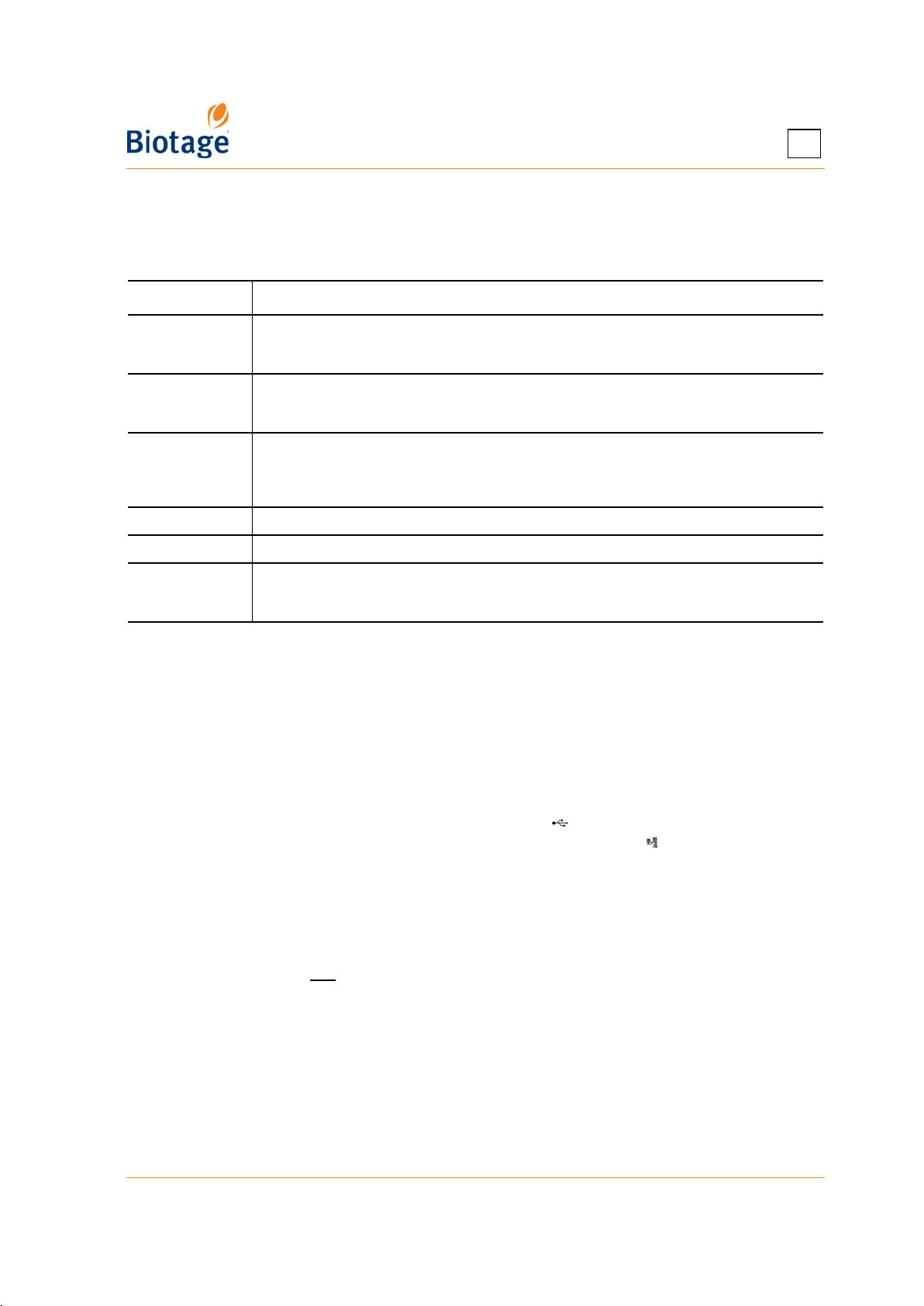
4
5. Specify the collection and fractionation settings to be used in the Parameters field. Refer to
Table 4-2 below for guidance. For more information; see the “Collection and Fractionation”
appendix on page A-1.
Table 4-2: Collection and Fractionation Parameters
Parameter Description
Start
Wavelength
End Wavelength The longest wavelength to be included in the λ-all signal. The range is 200 to 400 nm
Collect All Light absorbance of sample is monitored, but collection is based on the gradient’s total
Start Threshold Used to collect samples with an absorbance exceeding the set absorbance threshold.
Initial Waste Delay collection until a specified volume has been delivered to the waste.
Slope Collection is based on the start slope of light peaks. Refer to the “Collection and
The shortest wavelength to be included in the λ-all signal. The range is 200 to 400 nm
(dual variable UV detector) or 200 to 800 nm (UV-VIS detector). Note that this
parameter is only available with the λ-all detection mode.
(dual variable UV detector) or 200 to 800 nm (UV-VIS detector). Note that this
parameter is only available with the λ-all detection mode.
volume. When using the detection mode UV1+UV2 or UV1, valley fractionation is
enabled by default in the System mode. If disabled, fractionation is based on the max
fraction volume for the vessel type.
Fractionation” appendix on page A-1 for details. Note that slope collection is only
possible with the UV1 and UV1+UV2 detection modes.
Save and/or Run the Method
1. If you want to save the method and reuse it in the future:
a. To save the method in the system’s database, press Save. If your user account is
password-protected, the Password dialog opens. Enter your password, using the keypad,
and press OK.
b. To save the method on a USB memory device or the network:
1. Press Save As. The Save As dialog opens.
2. Select the user name and enter the method name by selecting the corresponding text box.
3. To save the method on a USB memory device, connect the device to the USB port
located underneath the touch screen and press Save.
4. To save the method in a share folder on your network, press Save. (If the button is
disabled, no file sharing has been set up. See “Set Up File Sharing and Auto Save of
Reports” on page 3-7.)
2. To run a purification using the (saved or unsaved) method, see “Prepare and Run a Purification”
on page 4-15.
NOTE
You do not have to save your method to be able to run it.
411829-L, Operation April 2012 Page 4-9
Page 60
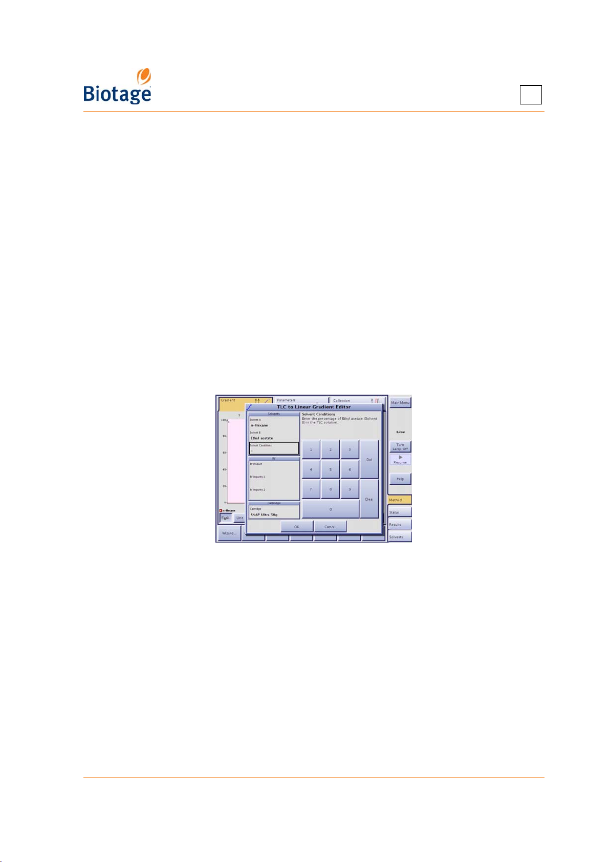
4
4.4.2 Calculate Gradient from TLC Data
Use the TLC to Linear Gradient editor or the TLC to Step Gradient editor (requires a Spektra license)
to calculate a purification gradient and get cartridge and sample load recommendations.
TLC to Linear Gradient
The software’s TLC to Linear Gradient editor is used to enter the following parameters obtained
from a TLC procedure:
values for the compound of interest and the closest eluting compounds on the leading and
•R
f
trailing sides of the compound of interest.
• Solvents and their percentages.
The software uses these values to calculate a purification gradient and recommend cartridge type
for your sample mass or vice versa.
1. Select the Method tab in the right-hand panel.
2. Press Optimize... and if the Optimize... dialog opens, press Open TLC to Linear Gradient
Editor. The TLC to Linear Gradient editor opens.
3. Select the two solvents to be used by selecting the Solvent A and Solvent B text boxes.
Normally the solvent with the lower solvent strength is selected as Solvent A.
4. Select the Solvent Conditions text box and enter the percentage of Solvent B in the TLC
solution.
Figure 4-6. TLC to Linear Gradient Editor
5. Select the Rf Product text box and enter the Rf value of the product of interest.
6. Enter the R
and Rf Impurity 2 text boxes. A value for Rf Impurity 1 is required.
7. Select the Cartridge text box and select a cartridge type with a loading capacity exceeding
your crude sample mass.
8. To save the data, press OK. The TLC to Linear Gradient editor closes and the software
calculates the purification gradient based on the TLC data and displays it at the Gradient tab.
9. Set up the rest of the method parameters; see “Specify the Method Parameters at the
Parameters Tab” on page 4-4 and “Specify Collection Parameters at the Collection Tab” on
page 4-8.
10. To save the method and reuse it in the future, see “Save and/or Run the Method” on page 4-9.
11. To run a purification using the (saved or unsaved) method, see “Prepare and Run a Purification”
on page 4-15.
411829-L, Operation April 2012 Page 4-10
value of the impurity closest below and above the product in the Rf Impurity 1
f
Page 61
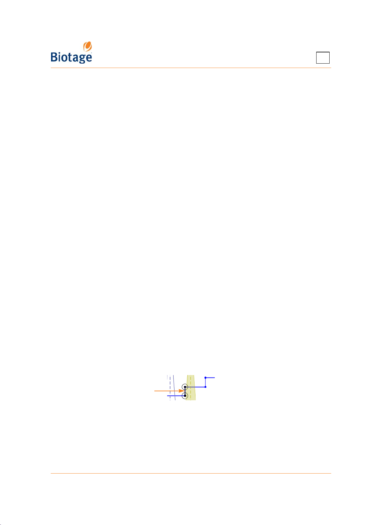
4
TLC to Step Gradient
The software’s TLC to Step Gradient editor is used to enter the following parameters:
• The R
• The percentage of the strongest solvent in the TLC solution, for each TLC plate.
• The crude sample mass.
The software uses these values to calculate a purification gradient and recommend a cartridge type.
Note the following when using the TLC to Step Gradient editor:
• At least two TLC plates with R
• Accuracy of prediction can be reduced if using alcohols, such as methanol and ethanol, very
• Reversed-phase chromatography is currently not supported.
• Store the TLC plates in a dry and dark place.
• Use only freshly prepared TLC solutions.
• Slight variation in migration rates will be observed if samples are applied too near to the
To create a purification gradient using the TLC to Step Gradient editor:
1. Select the Method tab in the right-hand panel.
2. Press Optimize.... The Optimize... dialog opens.
3. Press Open TLC to Step Gradient Editor. The TLC to Step Gradient editor opens.
4. Enter the percentage of the strongest solvent in the TLC solution, for each TLC plate, by
pressing the “0%” table headers.
To add a plate, press Add Plate....
To delete a plate, select its table header and press Delete Plate. Note that two plates are
required to predict the mobility of the compounds.
5. Enter the R
corresponding table cells. Valid range is 0.05 to 0.95.
To add a compound, press Add Compound....
To delete a compound, select its table header and press Delete Compound.
6. If desired, enter the name of each compound by pressing the compound table headers.
7. To view and modify (if desired) the predicted step gradient, select the Gradient and Peaks tab.
value for each compound of interest, for each TLC plate.
f
values greater than 0.04 are necessary to predict the mobility
f
of the compounds.
volatile modifiers such as diethyl ether, or additives that permanently alter the properties of
the silica.
edge of the TLC plate. Apply samples at least 10 mm from the edge to avoid the edge effect.
value for each compound of interest, for each TLC plate, by pressing the
f
• To exclude e.g. the last compound, select the second last compound by pressing on its
label and then press End Gradient At Selected Peak.
• To modify the outcome, drag a peak (by dragging the compound label) or a gradient
segment to the desired position.
Selected segment
8. If desired, select the compound of interest by pressing on its label and press Set Peak of
Interest.
9. When satisfied with the gradient, select the Cartridge Selection tab.
10. Select the Sample Mass text box and enter the crude sample mass.
11. Select the Cartridge text box and select a cartridge type with a loading capacity exceeding
your crude sample mass. If a peak of interest has been set (see step 8), the load capacity is
calculated according to the smallest CV between the peak of interest and the peak before and
411829-L, Operation April 2012 Page 4-11
Page 62
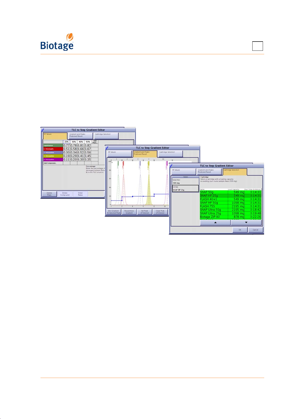
4
after. If no peak of interest has been set, the load capacity for each cartridge type is calculated
according to the smallest CV.
12. To close the TLC to Step Gradient editor and open a method containing the purification gradient
at the Method tab, press OK.
13. Set up the rest of the method parameters; see “Specify the Method Parameters at the
Parameters Tab” on page 4-4 and “Specify Collection Parameters at the Collection Tab” on
page 4-8.
14. To save the method and reuse it in the future, see “Save and/or Run the Method” on page 4-9.
15. To run a purification using the (saved or unsaved) method, see “Prepare and Run a Purification”
on page 4-15.
Figure 4-7. TLC to Step Gradient Editor
411829-L, Operation April 2012 Page 4-12
Page 63
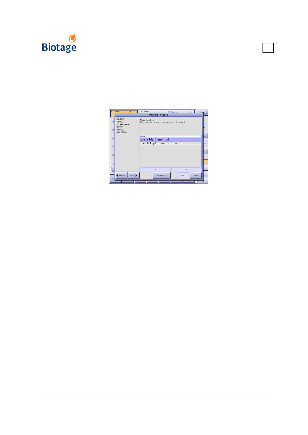
4
4.4.3 Create a Method Using the Method Wizard
The method wizard will guide you step-by-step through the setup of a purification with a gradient
including up to three steps using two solvents.
1. Select the Method tab in the right-hand panel.
2. Press Wizard.... The method wizard opens.
Figure 4-8. Method Wizard
3. Read and follow the instructions that appear on the screen. (See Table 4-1 on page 4-7 for
guidance in selecting rack type.)
4. If you want to save the method and reuse it in the future:
a. Press Save to Editor.
b. Enter a unique method name by selecting the Method Name text box at the
Parameters tab.
c. Press Save. If your user account is password-protected, the Password dialog opens.
Enter your password, using the keypad, and press OK.
5. To run a purification using the method, press Run....
6. Prepare the system as described on page 4-15.
7. Proceed with step 5 in “Run a Purification” on page 4-19.
4.4.4 Gradient Optimization
Linear gradients can be automatically optimized by converting them to step gradients which
reduces solvent use.
NOTE
Gradients that are optimized on an Isolera Prime, Isolera One, or Isolera
Four system cannot be run on an Isolera LS system due to the different
system volumes used for the calculation, and vice versa.
Clear separation between the peaks is required to receive a relevant result.
1. Select the Results tab in the right-hand panel.
2. Select the run at the Result Selection tab. For information on how to find the desired run, see
“Search for Records” on page 4-28.
3. Press Optimize.... The Gradient Optimization dialog opens.
411829-L, Operation April 2012 Page 4-13
Page 64
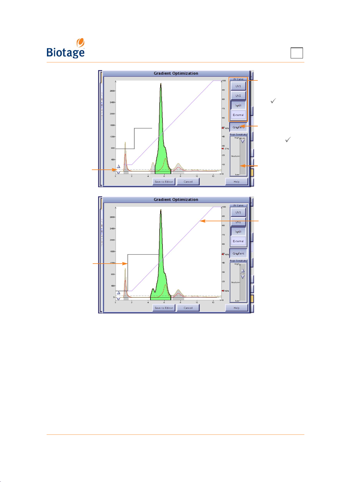
4
Select the curve
to base the
optimization
on ( )
Press to toggle
between
showing ( )
and hiding the
original gradient
Use this slider
to adjust the
threshold
Optimized step
gradient
Use this slider
to adjust the
peak sensitivity
Original
gradient
Figure 4-9. Gradient Optimization Dialog
4. To show the actual peaks, adjust the peak sensitivity and/or the threshold using the sliders (see
Figure 4-9).
5. Select/press the peak that you want to collect. The suggested step gradient is displayed.
6. When you are pleased with the result, press Save to Editor. The method is opened at the
Method tab and can be edited and/or saved.
4.4.5 Create a Method Using a Web Browser
See “Access the Isolera Remote Viewer” on page 4-35.
411829-L, Operation April 2012 Page 4-14
Page 65
4
4.5 Prepare and Run a Purification
4.5.1 Prepare the System for a Run
1. If no equilibration is to be performed and an internal dry loading technique is to be used (see
page 1-4), load the sample. See Table 4-3 on page 4-21 for cartridge loading capacity.
2. Load the cartridge (see Figure 4-10 on page 4-16) and collection rack(s) that you want to use.
3. If you want to use the sample loading pump (only available on Isolera LS), see “Prepare the
Sample Loading Pump for a Run (Only Isolera LS)” on page 4-17.
4. Ensure that a sufficient quantity of the correct solvent is present in each solvent reservoir and
that the waste reservoir has sufficient capacity for the run. To assign solvents and set reservoir
capacities and current levels, see page 4-32.
5. If you need to prime the system due to change of solvent or air bubbles, see page 4-33. Note
that all solvent inlets must be primed with solvent.
6. To turn on the detector lamp(s) in advance, press Turn Lamp On in the right-hand panel (in
the software).
NOTE
The UV lamp should be turned on approximately 7.5 minutes before
operation so it can warm up and stabilize.
If automatic rack allocation is enabled, the collection area must at all
times be loaded with racks in all positions.
All solvent inlets must be primed with solvent to achieve the specified
pump performance.
411829-L, Operation April 2012 Page 4-15
Page 66
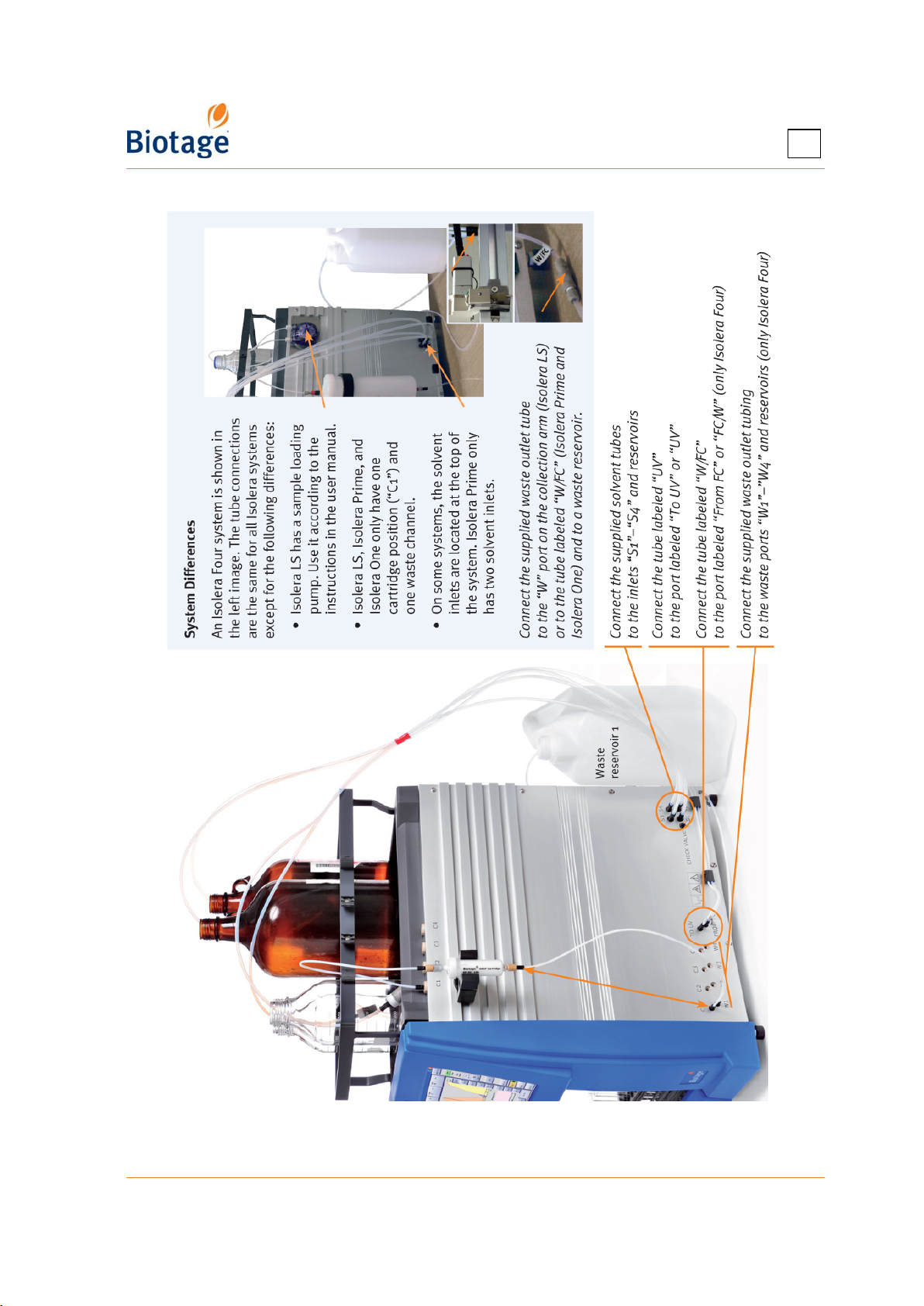
4
Figure 4-10. Tube Connections
411829-L, Operation April 2012 Page 4-16
Page 67
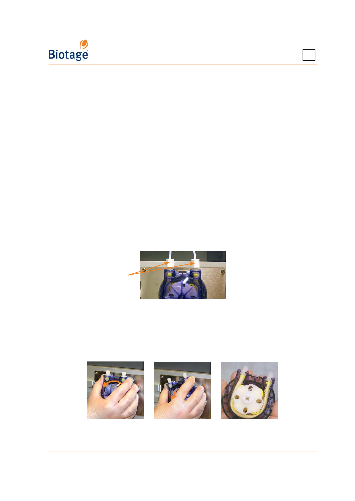
Prepare the Sample Loading Pump for a Run (Only Isolera LS)
NOTE
The peristaltic pump tube has limited use. To avoid the risk of crosscontamination and decreased pump performance, it is recommended that
the peristaltic pump tube is discarded after each run.
The system is delivered with two kinds of peristaltic pump tubes (PharMed
and Fluran). Ensure that the used peristaltic pump tube is compatible with
the solvents and sample to be used; see section 1.3.4 on page 1-20.
Samples to be loaded using the sample load pump must be fully dissolved.
Particulates in the sample may cut or weaken the peristaltic pump tube
causing a sample leak.
Only Isolera LS is equipped with the sample loading pump.
To empty the pump tubing of liquid and mount a new peristaltic pump tube:
1. Place the pump’s outlet line into a waste reservoir.
2. Select the Solvents tab in the right-hand panel (in the software) and then the Sample
Loading Pump tab.
3. Press Start to start the pump and draw air into the inlet line.
4. When the pump tubing is empty, press Stop.
5. Remove the inlet and outlet tubing by removing the two screws; see Figure 4-11.
4
Remove screws
Figure 4-11. Remove the Inlet and Outlet Tubing
6. Remove the pump by turning it counterclockwise and then pulling it out; see Figure 4-12.
7. Replace the tube inside the pump. Ensure that the new tube is compatible with the solvents and
sample to be used in the next run; see section 1.3.4 on page 1-20.
8. Remount the pump and the inlet and outlet tubing. If necessary, replace the inlet and outlet
tubing.
Figure 4-12. Remove the Sample Loading Pump
411829-L, Operation April 2012 Page 4-17
Page 68
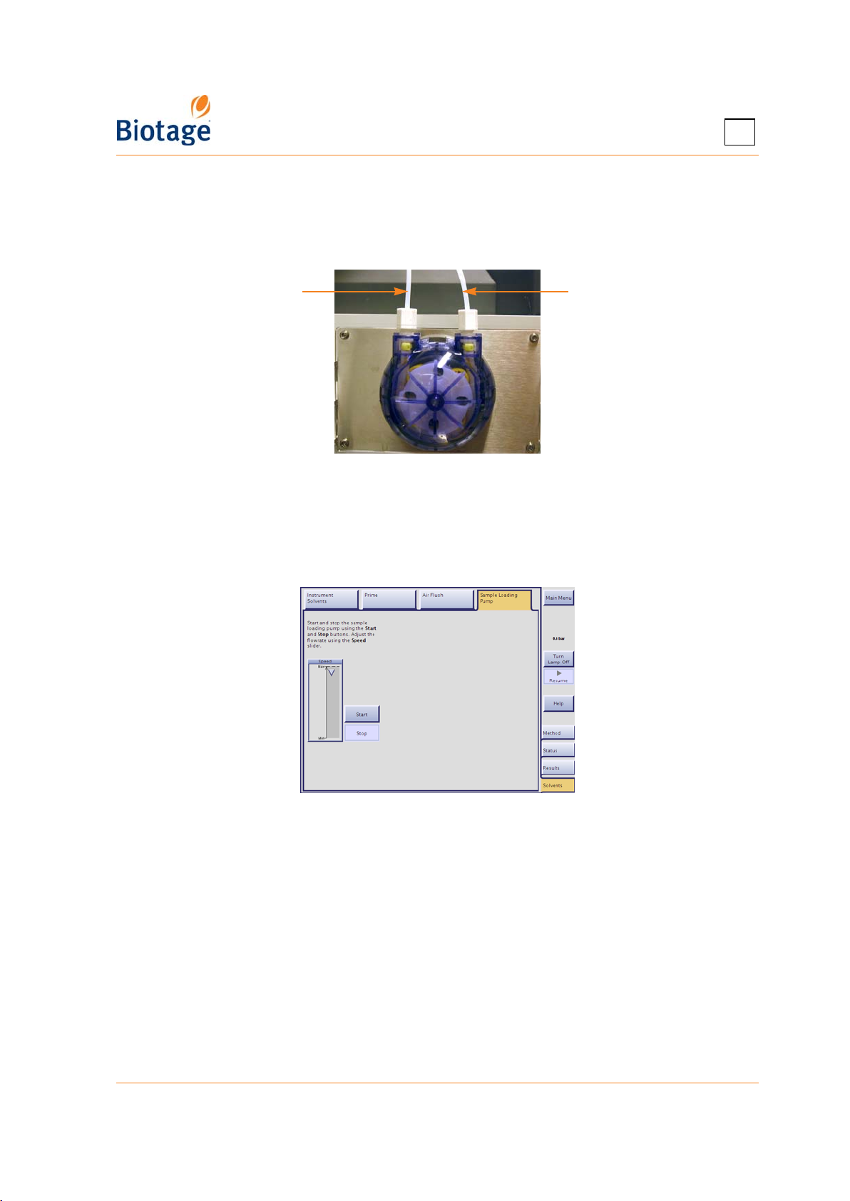
To reuse the peristaltic pump tube used in the previous run (not recommended – see the note
above), flush and fill the tubing with a solvent suitable for the next purification:
1. Place the pump’s inlet line into the solvent of your choice.
2. Place the pump’s outlet line into a waste reservoir.
Outlet line Inlet line
Figure 4-13. Sample Loading Pump
3. Select the Solvents tab in the right-hand panel (in the software) and then the Sample
Loading Pump tab.
4. To start the pump, press Start. Adjust the flow rate using the Speed slider.
5. When you are done, press Stop.
4
Figure 4-14. Sample Loading Pump Tab
6. Connect the pump’s outlet line to the cartridge’s inlet.
7. Place the pump’s inlet line into the sample.
411829-L, Operation April 2012 Page 4-18
Page 69

4.5.2 Run a Purification
WARNING
If you at any time during a purification need to pause the system, press
the Pause button in the right-hand panel (in the software). The collection
arm returns to its home position (the inner right corner) and the system is
paused. Note that the system is pressurized when it is paused. To resume
operation, press the Resume button.
1. Prepare the system as described on page 4-15.
2. Select the Method tab in the right-hand panel.
3. Open or create a new method, see “Create, Open, and Edit Methods” on page 4-2.
4. To run a purification using the displayed method, press Run.... The Run Parameters and
(if estimation is enabled) the Estimation dialog opens. To enable or disable estimation, see
“Enable or Disable Run Requirement Estimation” on page 3-10.
5. In the Run Parameters dialog:
a. Select/press the rack position(s) to be used ( ).
b. If using an Isolera Four system, select/press the cartridge position to be used ( ).
c. If the run is to be performed without equilibration and you want to inject a liquid sample
into the cartridge, you can either use a syringe or the sample loading pump (only
available on Isolera LS). See Table 4-3 on page 4-21 for cartridge loading capacity.
To use the sample loading pump: Press Load Sample and read and follow the
instructions in the Load Sample dialog. When you are done, press Close and connect the
cartridge inlet tubing to the cartridge’s inlet (see Figure 4-10). If you want to reuse the
peristaltic pump tube in the next run (not recommended), clean the tube with methanol
as soon as possible. Note that the sample loading pump can be cleaned while a
purification is in progress. For more information and instructions, see page 5-5.
4
NOTE
When using an Isolera Four system with automatic rack allocation
enabled, several runs (using the displayed method) can be queued up
simultaneously by selecting two or more cartridge positions in the Run
Parameters dialog.
6. In the Estimation dialog (if present), ensure that a sufficient quantity of the correct solvent is
present in each solvent reservoir, the waste reservoir has sufficient capacity for the run, and the
sufficient number of vessels have been allocated.
7. To start or queue up* the purification, press Equilibrate/Gradient (see Figure 4-15). The
Status tab is selected. Before the run is started, the system performs a UV Zero using the
gradient's initial solvent mix. Note that a gradient run is not started until the UV lamp is
sufficiently warmed up.
8. When the equilibration step (if included) is finished:
a. Load your sample; see “Sample Loading Methods for SNAP and SNAP Ultra Cartridges” on
page 1-4. If a liquid sample is used, press Load Sample... at the Status tab to enable
sample injection. The Load Sample dialog opens. To load a sample using the sample
loading pump (only available on Isolera LS), read and follow the instructions in the dialog.
When you have finished loading the sample, press Close and connect the cartridge inlet
tubing to the cartridge’s inlet (see Figure 4-10). See Table 4-3 on page 4-21 for cartridge
loading capacity.
b. Start or queue up* the gradient run by pressing Gradient at the Status tab.
* Purifications can be queued up when using an Isolera Four system.
411829-L, Operation April 2012 Page 4-19
Page 70
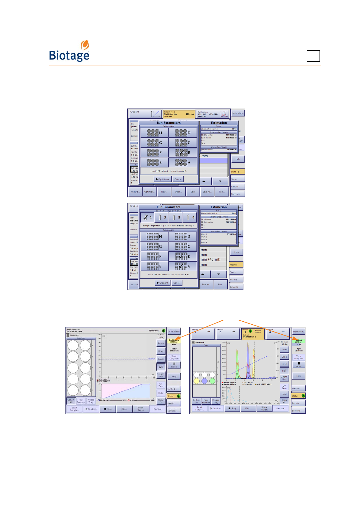
NOTE
When using an Isolera Four system, queued equilibrations take priority
over queued gradient runs.
Isolera One EXP and
Isolera LS
Rack positions for
120 ml racks:
4
Isolera Four EXP
Rack positions for
16x100 mm racks:
Figure 4-15. Run Parameters and Estimation Dialogs
Task field
Figure 4-16. Status Tab (Isolera LS and Isolera Four EXP
with Spektra License Shown)
411829-L, Operation April 2012 Page 4-20
Page 71

Table 4-3: Load Capacity Under Gradient Conditions
4
Cartridge
SNAP 10g* 15 10 100-200 200-350 350-500 10-20
SNAP 25g* 33 25 250-500 500-875 875-1250 20-40
SNAP 50g 66 50 500-1000 1000-1750 1750-2500 50-100
SNAP 100g 132 100 1000-2000 2000-3500 3500-5000 50-100
SNAP 340g 510 340 3400-6800 6800-8900 8900-17000
SNAP 750g
SNAP 1500g
SNAP HP 10g* 15 10 200-400 400-700 700-1000 10-20
SNAP HP 25g* 33 25 500-1000 1000-1750 1750-2500 20-40
SNAP HP 50g 66 50 1000-2000 2000-3500 3500-5000 50-100
SNAP HP 100g 132 100 2000-4000 4000-7000 7000-10000 50-100
SNAP HP 340g 510 340 6800-13600 13600-17800 17800-34000
SNAP Ultra 10g* 17 10 <200 200-1000 1000-2000 10-50
SNAP Ultra 25g* 45 25 <500 500-2500 2500-5000 20-100
SNAP Ultra 50g 85 50 <1000 1000-5000 5000-10000
SNAP Ultra 100g 164 100 <2000 2000-10000 10000-20000
SNAP Ultra 340g 582 340 <6800 6800-34000 34000-68000
SNAP C18 12g* 15 12 <60 <504 <996 5-20
SNAP C18 30g* 33 30 <210 <1740 <3000 15-40
SNAP C18 60g 66 60 <540 <4500 <7020 25-50
SNAP C18 120g 132 120 <2040 <8040 <14040 25-50
SNAP C18 400g 510 400 <11200 <26000 <40000 50-100
SNAP NH 11g* 15 11 100-200 200-350 350-500 10-20
SNAP NH 28g* 33 28 250-500 500-875 875-1250 20-40
SNAP NH 55g 66 55 500-1000 1000-1750 1750-2500 50-100
SNAP NH 110g 132 110 1000-2000 2000-3500 3500-5000 50-100
SNAP NH 375g 510 375 3400-6800 6800-8900 8900-17000
Biotage ZIP 5g* 8 5 50-100 100-175 175-250 5-20
Biotage ZIP 10g* 15 10 100-200 200-350 350-500 10-20
Biotage ZIP 30g* 45 30 300-600 600-1050 1050-1500 20-40
Biotage ZIP 45g* 60 45 450-900 900-1575 1575-2250 50-100
Biotage ZIP 80g 102 80 800-1600 1600-2800 2800-4000 50-100
Biotage ZIP 120g 170 120 1200-2400 2400-4200 4200-6000 50-100
FLASH 75S
FLASH 75M
FLASH 75L
Column
Volume
(ml)
§
§
§
§
990 750 7500-15000 15000-26000 26000-35500
‡
1980 1500 15000-30000 30000-52000 52000-76000 300-500
264 200 2000-4000 4000-7000 7000-10000
528 400 4000-8000 8000-14000 14000-20000
1056 800 8000-16000 16000-28000 28000-40000
Silica
Weight
(g)
Load Capacity
CV 0.1-1.9
(mg)
Load Capacity
CV 2.0-3.9
(mg)
Load Capacity
CV 4.0+
(mg)
Flow Rate
(ml/min)
65-300
100-500
65-300
30-150
30-150
65-325
65-300
100-500
100-500
100-500
†
†
†
†
†
†
†
†
†
†
* Cannot be used on Isolera LS.
†
When using Isolera Prime, the maximum flowrate is limited to 100 ml/min.
When using Isolera One or Isolera Four, the maximum flow rate is limited to 200 ml/min.
‡
Not recommended for use on Isolera Prime, Isolera One, or Isolera Four.
§
Not recommended for use on Isolera Prime.
411829-L, Operation April 2012 Page 4-21
Page 72
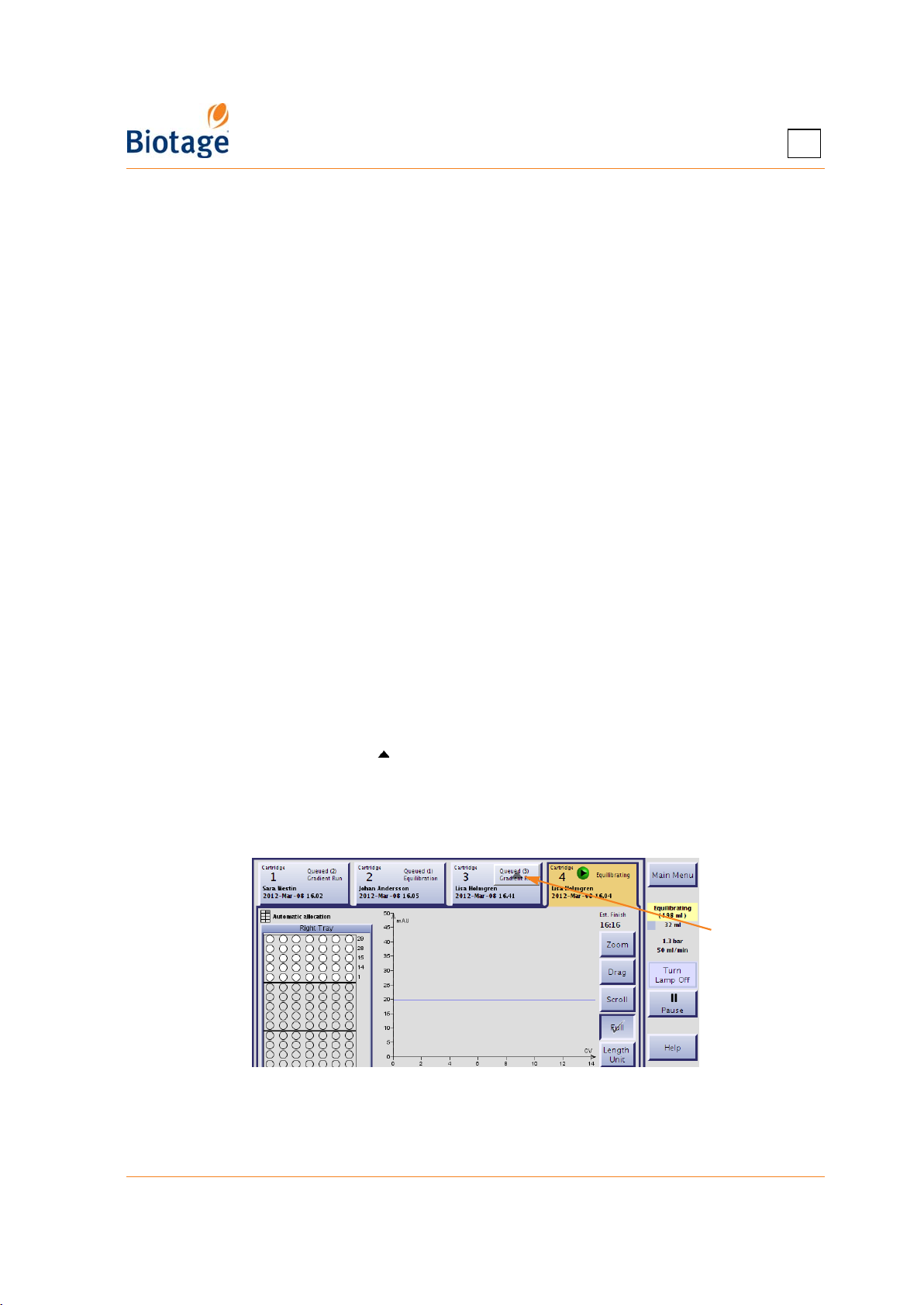
4
Replace and Allocate Racks During the Run
If more fractions are to be collected than can fit in the allocated rack(s), the system pauses, the
collection arm returns to the home position (the inner right corner), and the Load New Racks
dialog opens. Replace the rack(s) according to the dialog and press the Resume button to resume
the run. The collection is resumed in the first vessel in the lowest lettered rack. For example, if
racks B and C are allocated for the run, the collection is resumed in rack B in vessel 1.
You can at any time allocate free rack positions by pressing Edit... at the Status tab. (This is not
possible if automatic rack allocation is enabled.)
NOTE
When using an Isolera Four system with automatic rack allocation enabled,
you have to replace all racks in the collection area at the same time when
asked to (even if some of the racks have been used by previous runs).
Auto-Extend Mode
If the system is collecting fractions and remaining light absorption is detected when the system
nears the end of a purification, the system enters the Auto-Extend mode (if enabled in the system
mode). This extends the gradient purification stage of the run with 25% of the total gradient length
using the final conditions in the method.
Line Flush, Decompression, and Detector Flush
After the gradient purification stage is finished, the system performs a line flush (if enabled), air
flush (if enabled), system decompression, and a detector flush (if enabled). To enable or disable
flushes, specify whether enabled flushes are collected or not, and specify which solvents to use for
the flushes, see “Specify How Flushes Are Performed” on page 3-10. Note that the Air Flush feature
is not available with Isolera Prime.
4.6 Change the Processing Order
When using an Isolera Four system, it is possible to change the processing order. To move up a
purification in the queue, press the button at the Status tab; see Figure 4-17 below.
NOTE
Queued equilibrations take priority over queued gradient runs.
If you press this
button, the run
on cartridge 3
will be performed
prior to the run
on cartridge 1
Figure 4-17. Change the Processing Order
411829-L, Operation April 2012 Page 4-22
Page 73
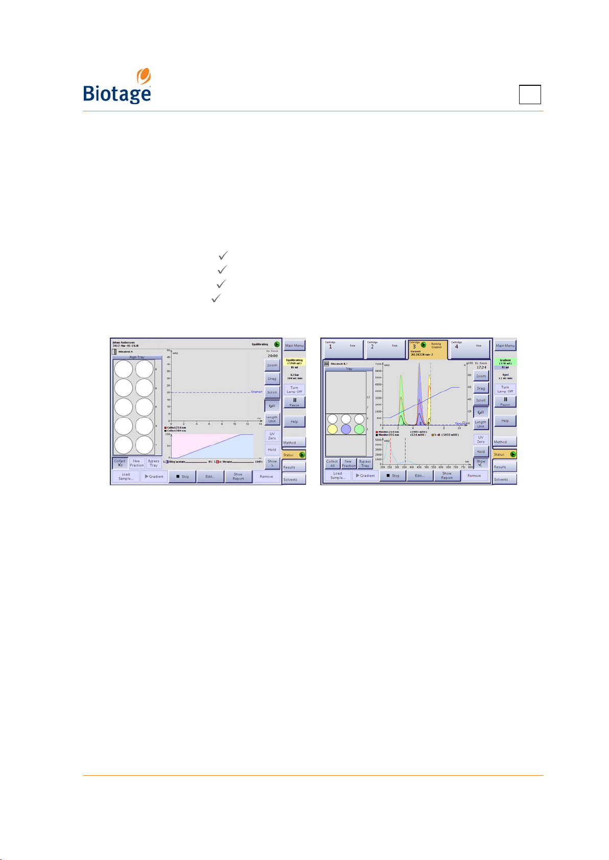
4
4.7 Monitor and Control a Purification
4.7.1 Monitor the Purification in Progress
Select the Status tab in the right-hand panel. While a purification is running, one graph displays
the programmed gradient and the other a dynamic chromatogram. If a Spektra license has been
installed on your system, an absorbance spectrum for the whole detector range can be viewed in
the gradient view by pressing the Show λ button. The gradient is then displayed in the
chromatogram.
You can adjust the chromatogram view by using the following buttons:
• Zoom: When enabled ( ), you can select a region of the chromatogram to magnify (zoom in).
• Drag: When enabled ( ), you can drag the chromatogram to the desired position.
• Scroll: When enabled ( ), the present reading +1 CV and -3 CV is shown on the horizontal axis.
• Full: When enabled ( ), all readings on the horizontal axis are shown.
• Length Unit: Toggle the horizontal axis unit between CV, minutes, and milliliter.
• UV Zero: Used to set the current UV level to 0 (zero) AU.
Figure 4-18. Status Tab (Isolera LS and Isolera Four EXP
with Spektra License Shown)
Cartridge Status and Color Legends
See page 1-13 for a description of the colors used in the tray overview, chromatogram, gradient
graph, and absorbance spectrum (requires a Spektra license).
See page 1-12 for a list of the different status of a cartridge.
4.7.2 Bypass the Automatic UV Lamp Warm-up Period
You can bypass the automatic UV lamp warm-up period by pressing Skip Warm Up in the right-
hand panel. However, if the UV lamp has not reached operating temperature, purification results
may not be optimal.
4.7.3 End Initial Waste and Start Collecting Fractions
If you want to end an Initial Waste phase prematurely and start collecting fractions, press Start
Collect at the Status tab.
411829-L, Operation April 2012 Page 4-23
Page 74
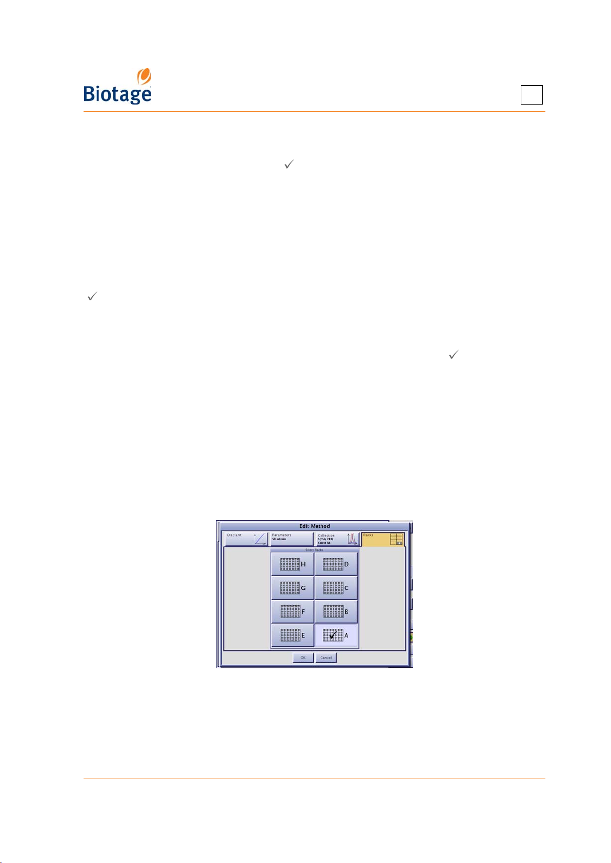
4
4.7.4 Collect Through the Waste Channel
If you want to start collecting fractions through the waste channel, press the Bypass Tray button
at the Status tab during the gradient run ( = collection through waste is enabled). You will be
requested to connect a collection vessel to the waste channel and enter the max collection volume
of the vessel. You can at any time switch to a new collection vessel by pressing New Fraction or
stop collecting through the waste channel and go back to collecting on the tray by pressing the
Bypass Tray button.
Fractions collected through the waste channel are colored in magenta in the chromatogram and
numbered W1, W2, and so on.
4.7.5 Start and End an Isocratic Segment
You can at any time during the gradient run start an isocratic segment by pressing the Hold button
( = isocratic hold is enabled). End the segment by pressing the Hold button again.
4.7.6 Control a Manual Collection
If you have set up a purification with manual collection, you can instruct the system to start and
stop collecting fractions by pressing the Collect All button at the Status tab ( = fractions are
collected). The system will fill each collection vessel according to the defined max fraction volume.
You can at any time switch to a new collection vessel by pressing New Fraction.
4.7.7 Edit and Manually Extend a Purification
If the system is collecting fractions and remaining light absorption is detected when the system
nears the end of a purification, the system enters the Auto-Extend mode (if enabled in the system
mode). This extends the gradient purification stage of the run with 25% of the total gradient length
using the final conditions in the method.
To edit and manually extend a purification:
1. Select the Status tab in the right-hand panel.
2. Press Edit.... The system is paused and the Edit Method dialog opens.
Figure 4-19. Edit Method Dialog
3. Edit the method settings.
4. To save the changes and resume the operation (if the system was paused), press OK.
411829-L, Operation April 2012 Page 4-24
Page 75

4
5. If you extended a finished run or edited a gradient run that was not started or queued up*,
press Gradient to start (or queue up*) the run. Note that if you extend a run on an Isolera
Four system and UV Zero has been performed on another cartridge in between, the system will
perform a UV Zero.
NOTE
When using an Isolera Four system, queued equilibrations take priority
over queued gradient runs.
* Purifications can be queued up when using an Isolera Four system.
4.7.8 Pause, End, or Abort a Purification
WARNING
Keep your hands out of range of the collection arm until it has stopped
moving (with the collection arm in the inner right corner).
The system is pressurized when it is paused.
Pause and Resume a Purification
1. To pause a purification in progress, press Pause in the right-hand panel (in the software). The
collection arm returns to its home position (the inner right corner) and the system is paused.
2. To resume the run from the point at which it was paused, press Resume in the right-hand panel.
End or Abort a Purification
1. Select the Status tab in the right-hand panel.
2. If the purification is in progress:
a. Press Stop. The collection arm returns to its home position (the inner right corner), the
system is paused, and the Stop dialog opens.
b. If you want the system to perform all enabled flushes and line purges, press End.
c. If you do
release any remaining pressure in the cartridge, press Purge... in the Purge dialog that
opens. (If there are queued runs*, the processing of the queue is started by pressing
Resume in the right-hand panel.)
3. If the purification is not started, i.e. the equilibration is finished but the gradient run is not
started or the run is queued up*, press Remove.
* Purifications can be queued up when using an Isolera Four system.
not want the system to perform the enabled flushes and purges, press Abort. To
411829-L, Operation April 2012 Page 4-25
Page 76
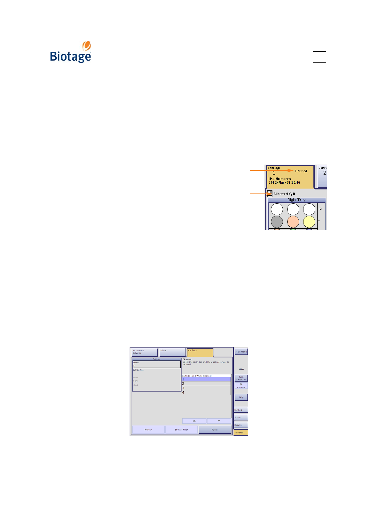
4
4.8 Unload a Purification
When the purification is finished (check that the cartridge’s status is “Finished” at the Status tab),
unload the cartridge and rack(s) as described below.
1. If necessary, empty the cartridge of remaining solvents and pressure by using the air flush and
purge features at the Solvents tab. See “Flush a Cartridge with Air” below and “Purge a
Cartridge” on page 4-27. Note that the Air Flush feature is not available with Isolera Prime.
2. If using an Isolera Four system and the system is processing, press Pause.
3. Unload the cartridge. To avoid leakage, plug the cartridge’s inlet and outlet fittings and couple
the inlet and outlet tubes together.
4. Unload the rack(s) used by the run. Allocated racks are listed at the Allocated heading at the
Status tab.
5. If using an Isolera Four system with
automatic rack allocation enabled, load
new, empty racks of the same type.
6. To clear the cartridge and rack
positions in the software, press
Remove.
7. To resume processing of queued runs*,
press Resume....
Cartridge status
Allocated racks
Figure 4-20. Cartridge Status and Allocated
Racks (Isolera Four EXP Shown)
* Purifications can be queued up when using an Isolera Four system.
4.8.1 Flush a Cartridge with Air
NOTE
It is not possible to flush a cartridge with air when using an Isolera Prime
system.
Empty the cartridge of remaining solvents using the Air Flush feature. If you want the system to
automatically perform an air flush at the end of a purification, enable the Air Flush option (see
“Specify How Flushes Are Performed” on page 3-10).
Figure 4-21. Air Flush Tab (Isolera Four Shown)
411829-L, Operation April 2012 Page 4-26
Page 77

4
To manually instruct the system to perform an air flush:
1. Select the Solvents tab in the right-hand panel.
2. Select the Air Flush tab.
3. If using an Isolera Four system, select the Channel text box and select the cartridge to be
flushed and the waste reservoir to be used.
4. Ensure the correct cartridge type is displayed in the Cartridge Type text box. To change,
select the Cartridge Type text box and select the cartridge type mounted on the system.
5. If you want to change the default flush volume, select the Volume text box.
6. For the pump to work properly, a small amount of solvent has to be used. By default the system
will flush with the weakest solvent used in the run. To change, select the Solvent text box and
select the desired solvent.
7. Ensure that a sufficient quantity of the selected solvent is present in the solvent reservoir (1% of
the air flush volume is used) and that the waste reservoir has sufficient capacity for the air flush.
8. To start flushing, press Start.
4.8.2 Purge a Cartridge
Any remaining pressure after a purification can be released using the purge feature.
1. Select the Solvents tab in the right-hand panel.
2. Select the Purge tab.
3. If using an Isolera Four system, select the Channel text box and select the cartridge to be
purged and the waste reservoir to be used.
4. Ensure that a waste reservoir is connected to the waste channel.
5. To purge, press Purge. The Purge dialog opens.
6. When the pressure has been reduced to an acceptable level, press End in the Purge dialog.
411829-L, Operation April 2012 Page 4-27
Page 78
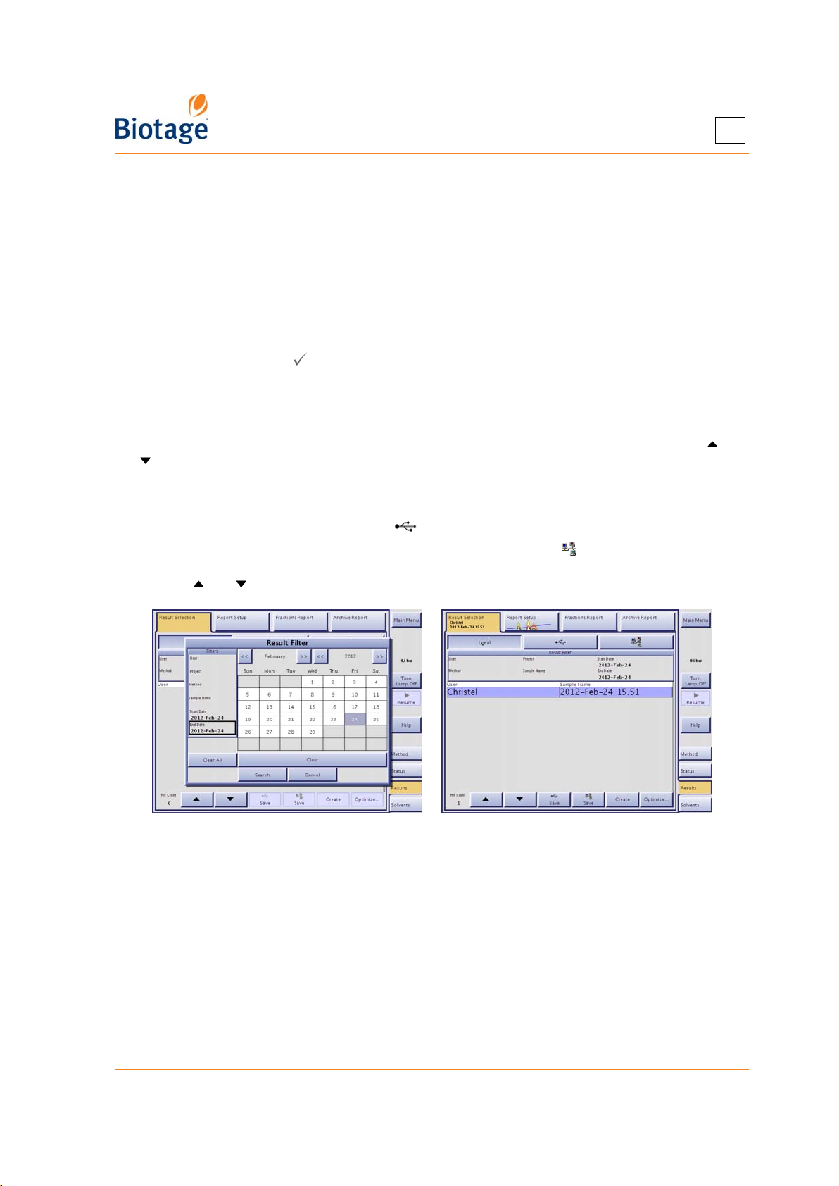
4
4.9 Access Result Records
4.9.1 Search for Records
Purifications that are processed on the system are stored as individual records in the system’s
database. Possible search criteria for these records are 1) user name, 2) project name, 3) method
name, 4) sample name, and 5) date when the purification was run.
To search for records in the system’s database:
1. Select the Results tab in the right-hand panel.
2. Select the Result Selection tab.
3. If Local is not selected ( ), press Local.
4. Press the Result Filter field. The Result Filter dialog opens.
5. Specify the filter settings. Note that the result filter is case sensitive. (If you want to list all
result records, press Clear All.)
6. To search, press Search. If there are records matching your search criteria, they are listed in
chronological order. If more records are found than can be displayed at one time, use the and
buttons to scroll through the records.
To search for records on a USB memory device or on the network:
1. To search records stored on a USB memory device, connect the device to the USB port located
underneath the touch screen and press .
2. To search records stored in the share folder on your network, press . (If the button is disabled,
no file sharing has been set up. See “Set Up File Sharing and Auto Save of Reports” on page 3-7.)
3. Use the and buttons to scroll through the records.
Figure 4-22. Search for Records
411829-L, Operation April 2012 Page 4-28
Page 79
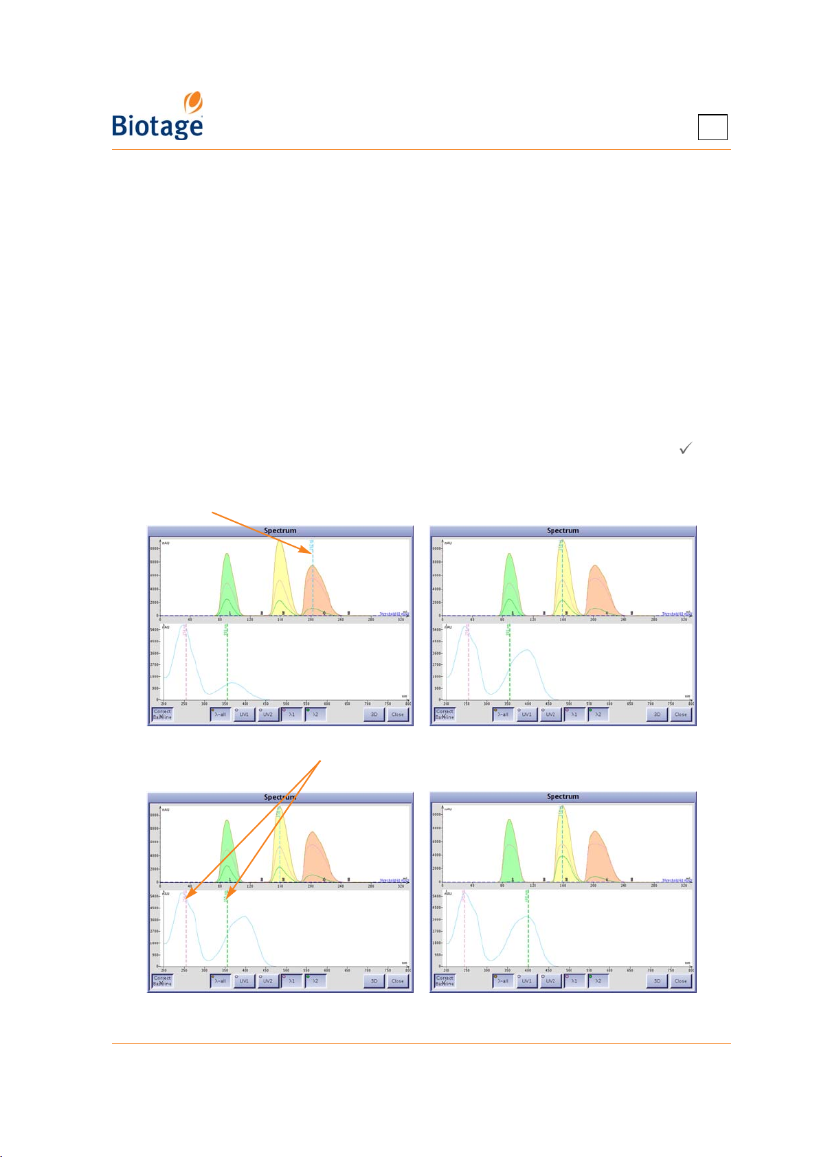
4
4.9.2 View, Print, and Save Reports on a USB Memory Device or the
Network
Two result reports are available for each purification: 1) an archive report with purification details, a
chromatogram, a 3D absorbance spectrum for the whole detector range (requires a Spektra
license), and TLC data (if entered in the TLC to Step Gradient editor) and 2) a fraction report. These
reports can be printed to a network printer with postscript support or a local USB printer and saved
as PDF files on a USB memory device or in a share folder on your network.
1. Select the Results tab in the right-hand panel.
2. Select the desired record at the Result Selection tab. (If the record is not listed, see “Search
for Records” above.) An archive report with purification details, a chromatogram, a 3D
absorbance spectrum for the whole detector range (requires a Spektra license), and TLC data
(if entered in the TLC to Step Gradient editor) for the selected record is available at the
Archive Report tab and a fraction report is available at the Fraction Report tab.
3. To view a 2D and 3D absorbance spectrum for the whole detector range (requires a Spektra
license):
a. Press λ... at the Report Setup tab. The Spectrum dialog opens.
b. To enable or disable baseline correction, press Correct Baseline. When enabled ( ), the
maximum solvent absorbance spectrum is subtracted from the signal presented by the
detector.
Drag this line to another position to show the absorbance spectrum at that time.
Drag one or both of these lines to other wavelengths to show the chromatogram at
those wavelengths.
Figure 4-23. 2D Absorbance Spectrum
411829-L, Operation April 2012 Page 4-29
Page 80
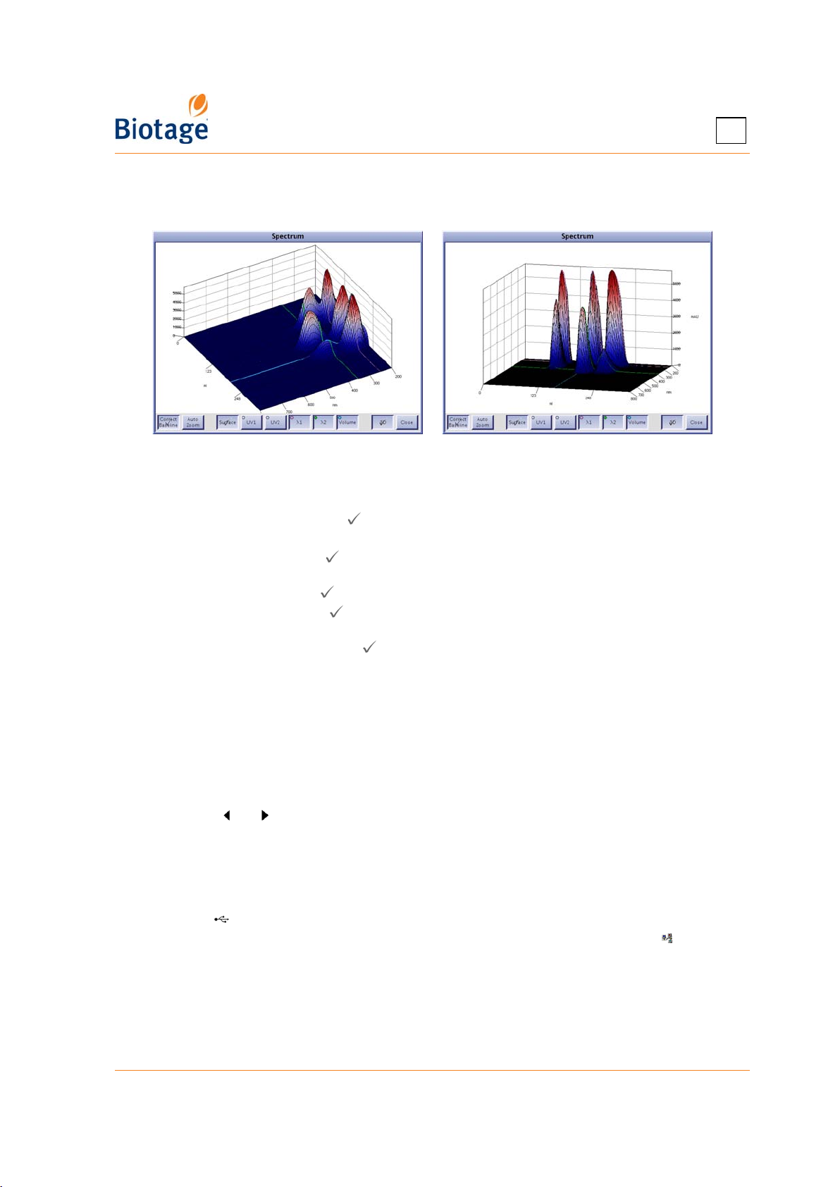
4
c. To show a 3D absorbance spectrum instead, press 3D. Drag the 3D spectrum to change
the perspective, see the examples below in Figure 4-24. Note that the way it looks here is
the way it will look in the archive report.
Figure 4-24. 3D Absorbance Spectrum in Different Perspectives
4. To modify the fraction and archive reports, select the Report Setup tab. The following buttons
can be used to modify the reports:
• Gradient: When enabled ( ), the programmed gradient is shown in the chromatogram.
• Reset Zoom: Reset the zoom to default.
• Zoom: When enabled ( ), you can select a region of the chromatogram to magnify
(zoom in). This is useful when the chromatogram displays many fractions close together.
• Drag: When enabled ( ), you can drag the chromatogram to the desired position.
• Select: When enabled ( ), you can select and deselect fractions in the chromatogram.
(Fractions can at any time be selected and deselected in the tray overview.)
• Peak Mode: When enabled ( ), you can select a peak by selecting one of its fractions.
All fractions of a peak have the same color.
• Select All: Select all fractions.
• Deselect All: Deselect all fractions.
• λ...: Modify how the 3D absorbance spectrum is presented in the archive report. See step 3
above.
• Length Unit: Change the horizontal axis (the x-axis) unit by pressing the button
repeatedly until the desired unit appears; CV, minutes, or milliliter.
If there was one or more rack changes during the run, or the run was performed on a system
with two collection trays with allocated racks on both trays, toggle between the racks by
pressing the and buttons.
5. To print the archive or fraction report to the (local or network) printer connected to the system,
press Print at the corresponding tab. (If the button is disabled, no printer has been installed.
See “Set Up a Printer and Auto Print of Reports” on page 3-6.)
6. To save the selected report as a PDF file on a USB memory device:
a. Connect a USB memory device to the USB port located underneath the touch screen.
b. Press Save. The report is saved at “USB”:\biotage\isolera\results.
7. To save the selected report as a PDF file in a share folder on your network, press Save. The
report is saved at “share folder”\biotage\isolera\results\. (If the button is disabled, no file
sharing has been set up. See “Set Up File Sharing and Auto Save of Reports” on page 3-7.)
411829-L, Operation April 2012 Page 4-30
Page 81
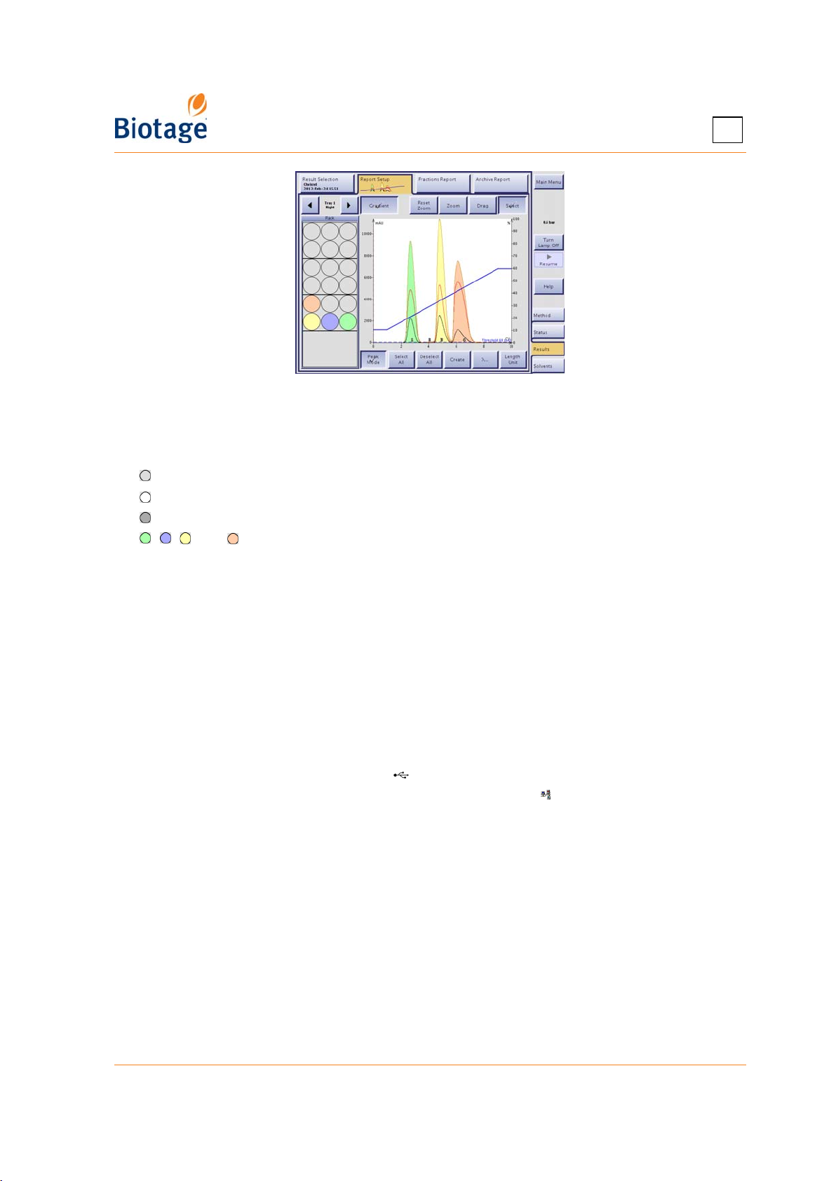
Figure 4-25. Report Setup Tab
Color Legend
The colors used at the Report Setup tab are:
= The vessel has not been used for the viewed purification.
= The vessel is deselected.
= The vessel is selected and contains flush liquid.
, , , and = The vessel is selected and contains a fraction. (The vessel color corresponds
with the fraction color in the chromatogram.)
4
If fractions are collected through the waste channel (i.e. the Bypass Tray mode is enabled), the
fractions are colored in magenta in the chromatogram and numbered W1, W2, and so on.
4.9.3 Save Records on a USB Memory Device or the Network
Purifications that are processed on the system are stored as individual records in the system’s
database. The records can, if desired, be saved by the user as XML files (text files including all raw
data) on a USB memory device or in a share folder on the network. The XML files can be opened on
any Isolera system with the same or newer version of the software.
1. Select the Results tab in the right-hand panel.
2. Select the desired record. (If the record is not listed, see “Search for Records” on page 4-28.)
3. To save the record on a USB memory device, connect the device to the USB port located
underneath the touch screen and press Save.
4. To save the records in the share folder on your network, press Save. (If the button is
disabled, no file sharing has been set up. See “Set Up File Sharing and Auto Save of Reports” on
page 3-7.)
4.10 View System Status and Results from Your Office
See “Access the Isolera Remote Viewer” on page 4-35.
411829-L, Operation April 2012 Page 4-31
Page 82
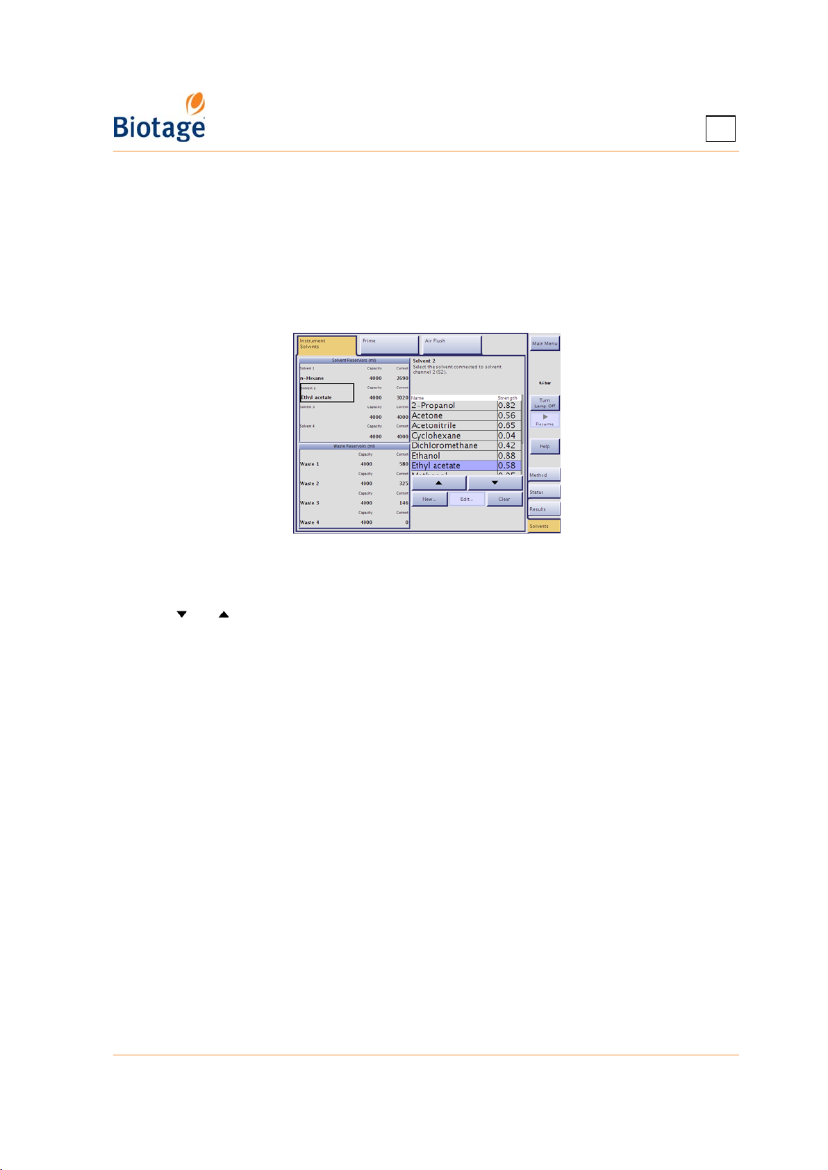
4.11 Solvent and Waste Handling
4.11.1 Assign Solvents to the Solvent Inlets
When a purification is run, the software references the solvent assignments to determine which
solvent inlets that are connected to the solvents used in the method.
1. Select the Solvents tab in the right-hand panel.
2. Select the Instrument Solvents tab.
4
Figure 4-26. Solvents Tab (Isolera Four Shown)
3. Press one of the Solvent text boxes.
4. Select the solvent that you want to assign to the selected inlet. To scroll the list down or up,
press and . The software comes with a preconfigured list of solvents and their parameters.
You may add other solvents to this list (press New...) and edit user defined solvents (select the
solvent and press Edit...).
5. If solvent monitoring is enabled, select the Capacity text box and enter the capacity of the
solvent reservoir.*
6. If solvent monitoring is enabled, select the Current text box and enter the current solvent level
of the reservoir.*
7. Repeat step 3 through 6 for all solvent inlets.
* These values are used by the system to track reservoir capacity. To enable this feature, see “Enable or
Disable Monitoring of Reservoirs” on page 3-9.
4.11.2 Set the Reservoir Volumes
If the monitoring of solvent and/or waste levels is enabled (see “Enable or Disable Monitoring of
Reservoirs” on page 3-9), you have to enter the capacities and current fluid levels for the solvent
and waste reservoirs each time you empty a waste reservoir or replenish a solvent.
1. Select the Solvents tab in the right-hand panel.
2. Select the Instrument Solvents tab.
3. Enter the capacity of a reservoir by pressing the applicable Capacity text box.
4. Enter the current level of a reservoir by pressing the applicable Current text box.
411829-L, Operation April 2012 Page 4-32
Page 83
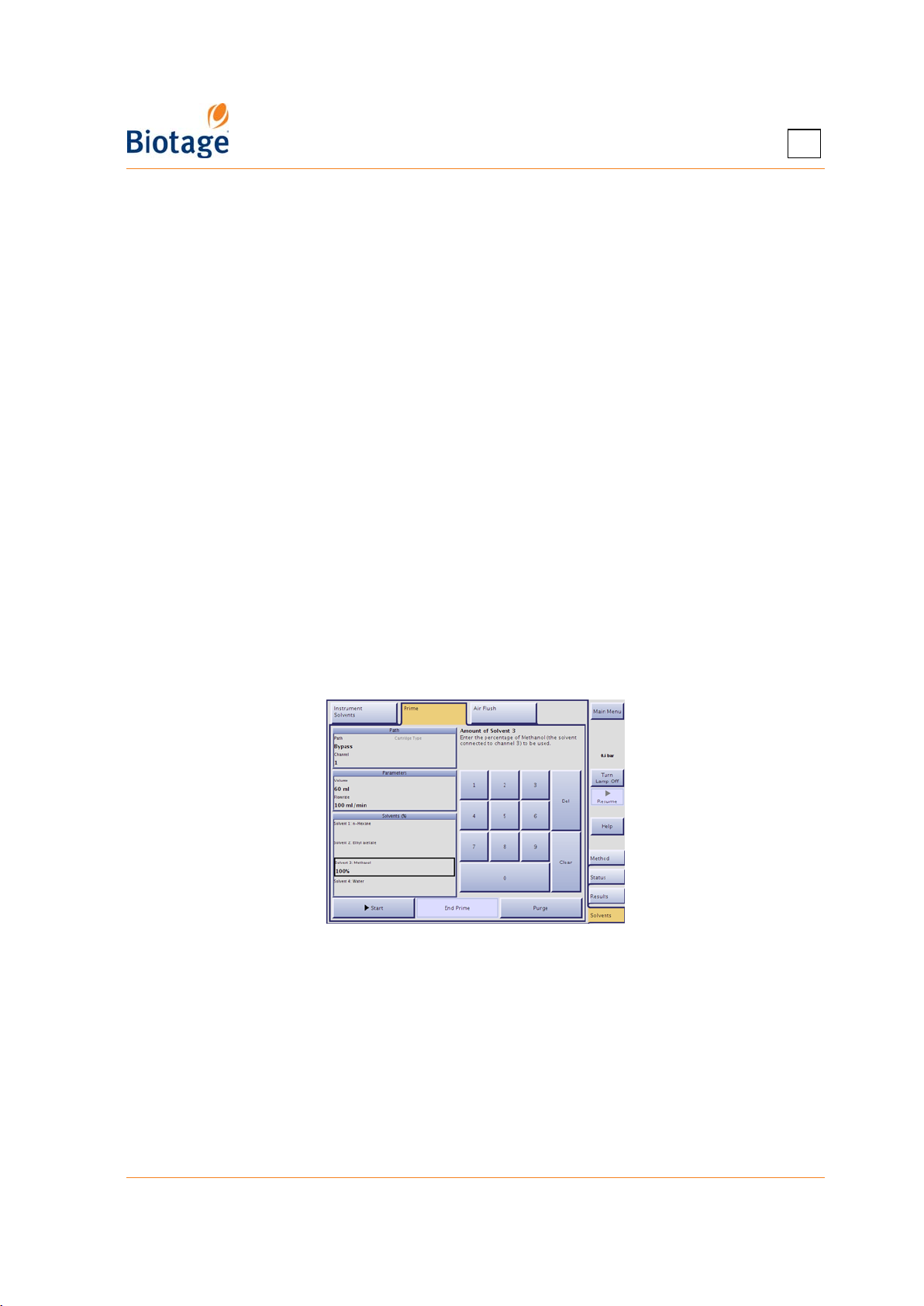
4
4.11.3 Prime the System
Before you start a purification on your Isolera system, you might need to prime the solvent inlets to:
• Remove any air bubbles from the pump and the solvent inlets by flushing them with solvents.
• Empty the solvent inlets of solvents used in the previous purification and fill them with new
solvents.
WARNING
Never prime the Isolera system without a cartridge mounted on the
system or without the cartridge’s inlet and outlet tubing coupled together.
To avoid leakage, check all tubes and fittings before priming the system.
NOTE
All solvent inlets must be primed with solvent to achieve the specified
pump performance.
To prime the system:
1. Ensure that a sufficient quantity of the solvent(s) you want to use is present in the solvent
reservoir(s) and the waste reservoir has sufficient capacity for the prime.
2. Select the Solvents tab in the right-hand panel.
3. Ensure that the solvents are assigned accurately to the solvent inlets at the Instrument
Solvents tab. If the capacity and current volume values are available for the waste and/or
solvent reservoirs (i.e. the monitoring of levels is enabled), check that the values are correct.
To make changes, see “Assign Solvents to the Solvent Inlets” and “Set the Reservoir Volumes”
on page 4-32.
4. Select the Prime tab.
Figure 4-27. Prime Tab (Isolera Four Shown)
5. If using an Isolera Four system, select the Channel text box and select the cartridge position
and waste reservoir to be used.
6. Select the Path text box and select the prime path. If you do not want to prime the cartridge,
press Bypass.
7. If you selected the path With Cartridge, select the Cartridge Type text box and select the
cartridge type mounted on the system.
8. Select the Volume text box and enter the total prime volume.
If you want to fill a solvent inlet with a new solvent, we recommend that you prime with at least
40 ml (when using an Isolera Prime, Isolera One, or Isolera Four system) or 50 ml (when using
an Isolera LS system) of that solvent. If you also want to fill the liquid lines from the pump to
411829-L, Operation April 2012 Page 4-33
Page 84

4
the (selected*) waste valve with the same solvent, we recommend that you prime with at least
60 ml when using an Isolera Prime, Isolera One, or Isolera Four system or 100 ml when using
an Isolera LS system.
9. Select the Flowrate text box and enter the flow rate. The maximum flow rate that can be used
depends on:
• the maximum fill rate(s) defined for the used solvent(s) in the Data Administration mode,
and
• the maximum dispense rate of the system (200 ml/min for Isolera Prime, One and Four,
and 500 ml/min for Isolera LS) or, if using an external detector, the maximum dispense
rate defined for the external detector in the System mode.
As a single-piston pump only delivers liquid during the dispense stroke, the maximum flow rate
when using an Isolera Prime system is equal to (Max Fill Rate x Max Dispense Rate)/(Max Fill
Rate + Max Dispense Rate).
80 ml/min and you use a external detector with the maximum dispense rate of 100 ml/min, the
highest flow rate that can be used is (50x100)/(50+100)=33 ml/min. If the external detector is
disabled, the highest flow rate that can be used is (50x200)/(50+200)=40 ml/min.
10. Enter the percentage of each solvent connected to the system that shall be used in the prime.
If using an Isolera LS system and a solvent inlet line is empty or filled with air bubbles, you
should prime it separately. (If several solvents are listed and you only want to use one solvent,
enter “100” for the solvent that you want to use and enter “0” or press Clear for the other
solvent(s).)
11. To start priming, press Start.
* When using an Isolera Four system.
Examples: If the fill rates for the used solvents are 50 ml/min and
411829-L, Operation April 2012 Page 4-34
Page 85
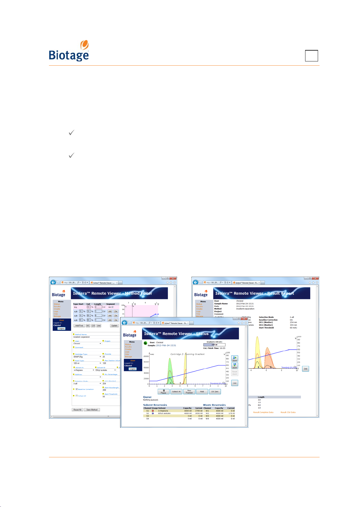
4
4.12 Access the Isolera Remote Viewer
With the system connected to your network, it is possible to perform the following tasks through a
standard web browser (through the Isolera Remote Viewer feature):
• Create a new method. If desired, the method can be based on a previous purification found
in the Results view.
• Check the status of the system and the progress of a purification.
• Instruct the system to start and stop collecting fractions by clicking the Collect All button
( = fractions are collected).*
• Instruct the system to switch to a new collection vessel by clicking the New Fraction button.*
• Instruct the system to start and end an isocratic segment by clicking the Hold button
( = isocratic hold is enabled).*
• Instruct the system to pause the purification in progress by clicking the Pause button. For
safety reasons, it is only possible to pause and not resume a run from your office.
• Instruct the system to set the current UV level to 0 (zero) AU by clicking the UV Zero button.*
• View, print, and export purification results.
* You must be logged in as the user defined in the purification run.
To access the Isolera Remote Viewer:
1. Enter the URL http://MACHINENAME in a web browser (where MACHINENAME is the hostname
or the host IP address). The hostname and host IP address are available in the About dialog at
the main menu.
2. Press ENTER and the Isolera Remote Viewer web page is loaded. The page is automatically
updated every five seconds.
NOTE
If you need help accessing the Isolera Remote Viewer, contact your IT
administrator.
Figure 4-28. Isolera Remote Viewer
(System with Four Solvent Inlets and Spektra License Shown)
411829-L, Operation April 2012 Page 4-35
Page 86

Chapter
Maintenance
5
WARNING
Before performing any procedures in this chapter, please read and observe
the safety requirements in the “Isolera Installation and Safety” document
(P/N 411828). Failure to follow those requirements may result in personal
injury and/or equipment damage. If the system has been damaged and
does not function properly, shut it down and contact Biotage 1-Point
Support immediately.
5.1 Contact Biotage 1-Point Support
If your system has been damaged and does not function properly, shut it down and contact Biotage
1-Point Support. See contact details on page 7-1.
5.2 Accessories
To order cartridges, please see the Biotage Product Catalog. The catalog can be downloaded at
www.biotage.com. For a complete list of accessories, please contact you local representative.
5.2.1 All Isolera Systems
Accessory Quantity Part Number
Test tube rack, 18 x 130 mm (for 17.5 x 130 mm test tubes)
Not recommended on Isolera LS.
Test tube rack, 18 x 150 mm 4 411792
Test tube rack, 25 x 150 mm 4 411793
Bottle rack, 120 ml 4 411794
Bottle rack, 240 ml 1 411934
Bottle rack, 480 ml 1 411929
120 ml bottles 96 08742
240 ml bottles 84 08743
480 ml bottles 24 411935
Rack number guide for 18 x 130 mm and 18 x 150 mm racks 4 413176
Rack number guide for 25 x 150 mm rack 4 413175
Collection tray for Isolera racks 1 411853
Cartridge holder for SNAP and SNAP Ultra 50g to 120g 1 411923
Cartridge holder for SNAP and SNAP Ultra 340g to 400g 1 411924
Cartridge holder nut 1 411340
4 412593
411829-L, Maintenance April 2012 Page 5-1
Page 87
5
Accessory Quantity Part Number
Leak detector for systems with one collection tray (Prime, One, and Four
systems)
Leak detector for systems with two collection trays (EXP and LS systems) 1 412062
1 412019
5.2.2 Isolera Prime, Isolera One, and Isolera Four
Accessory Quantity Part Number
Test tube rack, 13 x 100 mm 4 411789
Test tube rack, 16 x 100 mm 4 411790
Test tube rack, 16 x 150 mm 4 411791
Rack number guide for 13 x 100 mm rack
Rack number guide for 16 x 100 mm and 16 x 150 mm racks 4 413177
Expanded bed upgrade 1 411926
Cartridge holder for SNAP and SNAP Ultra 10g to 12g 1 411922
Cartridge holder for SNAP and SNAP Ultra 25g to 30g 1 411776
Sample injection valve, 3-way 1 FIV-VLV-1000
Sample injection valve (3-way) to SNAP or SNAP Ultra cartridge adapter 1 411081
Biotage ELSD-1080, external detector 1 ISO-ELSD-
4 413178
1080
5.2.3 Isolera LS
Accessory Quantity Part Number
Sample pump tube, PharMed (limited use)
Peristaltic pump tube, incl. connectors. See the chemical resistance
properties on page 1-20.
Sample pump tube, Fluran (limited use)
Peristaltic pump tube, incl. connectors. See the chemical resistance
properties on page 1-20.
Sample pump tube, ChemSure
Peristaltic pump tube, incl. connectors. Can be used with both non-polar
and polar solvents.
Cartridge holder for SNAP 750g and 1500g 1 412422
Male Luer fitting for SNAP 750g and 1500g 1 412537
Female Luer fitting for SNAP 750g and 1500g 1 412358
Sample injection valve, 3-way 1 413027
Funnel rack kit including two racks, portable cart, bottle board, positioning
shafts (for the bottles), and leak detector
1 412480
1 412481
1 412482
1 FNRK-032
411829-L, Maintenance April 2012 Page 5-2
Page 88
5
5.3 Spare Parts
A list of spare parts is available at www.biotage.com.
5.4 Clean the Exterior of the System
Regular cleaning of the touch screen, if performed properly, extends the touch screen life and
protects it from contaminants that cause unnecessary wear. Always turn the system off before
cleaning the screen.
WARNING
When cleaning the touch screen, use only non-ammonia based window
cleaner and do not apply the liquid directly to the screen as this could
introduce liquid into the screen electronics section, which could damage
electronic components.
NOTE
Avoid harsh cleaners and chemicals, and getting moisture inside the system.
1. Shut down the system as described on page 4-1.
2. Disconnect the power cord from the power outlet.
3. To clean the touch screen, wipe with a clean, non-abrasive, dry cloth. If this does not clean the
screen properly, then you may apply a small amount of non-ammonia based window cleaner
to a clean, non-abrasive cloth and then wipe the screen with the damp cloth. The cleaning liquid
must be applied to the cloth only. After cleaning, wipe dry with a clean, non-abrasive cloth.
4. To clean the exterior of the system, clean the surfaces using a clean, lint-free cloth, lightly
dampened with water. If required, a small amount of mild soap may also be used. After
cleaning, wipe dry with a clean, lint-free cloth.
5.5 Implement a Mobile Phase Change
To avoid faults during a mobile phase change, it is necessary to perform the change throughout the
entire chromatographic system (i.e. in the reservoir, pump, injector, column, and detector). The
procedure is to fill and flush the system, using the prime function (see page 4-33), with a series of
mutually miscible solvents until a gradual change to the new mobile phase (solvent) is
accomplished. If this procedure is not observed, precipitation may occur not only in the detector
flow cell but also in other parts of the system. For example, to change from an organic mobile
phase to aqueous solutions, it is necessary to flush the whole system with acetone or an alcohol
(e.g. isopropanol).
5.6 Clean the Detector Flow Cell
WARNING
Ultraviolet (UV) light can injure your eyes. Do not operate the Isolera
system with the detector flow cell removed and the retaining latch open.
Keep the detector flow cell clean and protect it from dust and chemical spills. Particular attention
should be paid to preventing the flow cell from leaking.
A dirty cell has decreased transmissivity, which causes increased noise level, decreased response,
and difficulties performing both auto and manual UV Zero functions.
411829-L, Maintenance April 2012 Page 5-3
Page 89
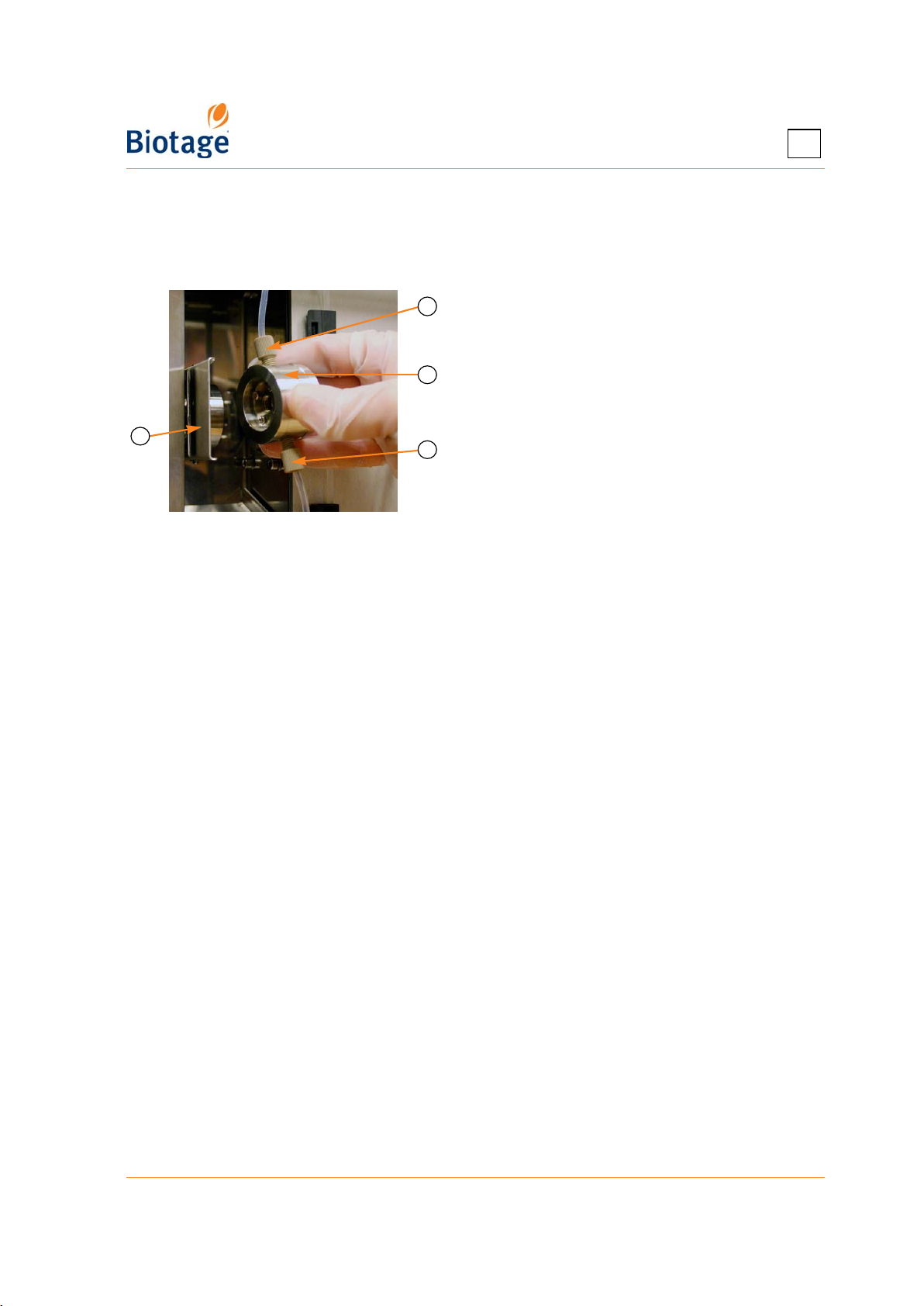
5
To clean the detector flow cell:
1. Shut down the system as described in on page 4-1.
2. While placing one hand under the flow cell (to prevent it from falling), pull outward on the
retaining latch to unlock the flow cell, and then carefully remove the flow cell from the system.
A
NOTE
The retaining latch should close with
little effort. If the retaining latch is
difficult to close, the flow cell is probably
B
D
C
misaligned.
A Flow Cell Outlet Tube
B Flow Cell
C Flow Cell Inlet Tube
D Opened Retaining Latch
Figure 5-1. Remove the Detector Flow Cell (Isolera Prime, One, and Four Shown)
3. Disconnect the inlet and outlet tubing from the flow cell and visually inspect the cell for
contamination.
4. Flush the flow cell with a series of miscible solvents. Select the solvents based on the
contamination. It is possible to use both organic and inorganic solvents and diluted solutions of
acids (e.g. H
attack stainless steel, PTFE, or fused silica windows.
5. Visually re-examine cell windows for visible contamination. If contamination is still present,
repeat step 4. If you are not able to remove the contamination, replace the flow cell (P/N 09869
for Isolera Prime. One, and Four systems and P/N 412324 for Isolera LS systems) and perform
an absorbance calibration (see “Calibrate the Internal Detector” on page 3-13).
6. Reconnect the tubing to the flow cell.
7. Carefully insert the flow cell and close the retaining latch.
or HNO3 diluted with distilled water in a ratio of 1:20 to 1:10), unless they
2SO4
5.7 Clean or Release Valves
5.7.1 Clean the Pump Check Valves
If the last purification of the day is performed with a halogenated solvent (e.g. DCM), we
recommend that you flush the pump check valves with methanol or a similar solvent. Use the
following procedure to flush the pump check valves.
1. Place the solvent inlet line used with the halogenated solvent into methanol or a similar solvent.
2. Ensure that the waste reservoir has sufficient capacity for the flush.
3. Select the Solvents tab in the right-hand panel.
4. Select the Prime tab.
5. If using an Isolera Four system, select the Channel text box and select the cartridge position
and waste reservoir to be used.
6. Select the Path text box and press Bypass.
7. Ensure that the cartridge’s inlet and outlet tubing are coupled together.
8. Select the Volume text box and enter the total flush volume. We recommend that you flush with
at least 30 ml (Isolera Prime), 60 ml (Isolera One and Isolera Four), or 100 ml (Isolera LS).
411829-L, Maintenance April 2012 Page 5-4
Page 90
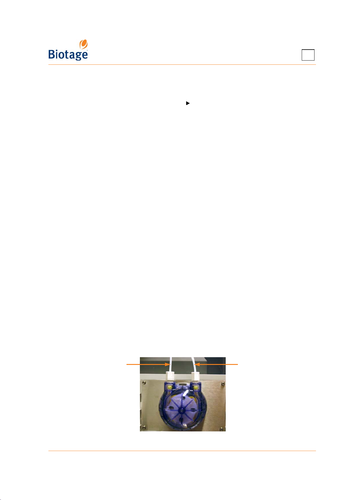
5
9. Select the Flowrate text box and set the flow rate to 100 ml/min (Isolera Prime), 200 ml/min
(Isolera One and Isolera Four) or 500 ml/min (Isolera LS).
10. Enter 100 percentage for the solvent inlet line used for methanol. Enter “0” or press Clear for
the other solvents that are connected.
11. To start flushing the pump check valves, press Start.
5.7.2 Release Stuck Check Valves
Low or inconsistent flow delivery volume and/or superimposed periodic UV signals can be signs of
sticking check valves. Use the following procedure to release stuck check valves.
1. Log into the System mode; see page 3-1.
2. Select the Maintenance tab in the right-hand panel.
3. Press Release Check Valves in the Valves field. Read and follow the instructions that appear
on the screen.
5.7.3 Clean the Collect Valve
Dripping needle and/or inconsistent dispensing volumes can be signs of a dirty collect valve. Use
the following procedure to clean the collect valve.
1. Select the Maintenance tab in the right-hand panel.
2. Press Clean Collect Valve in the Valves field. Read and follow the instructions that appear on
the screen.
5.8 Clean or Replace the Sample Loading Pump Tubing
NOTE
The peristaltic pump tube has limited use. To avoid the risk of crosscontamination and decreased pump performance, it is recommended that
the peristaltic pump tube is discarded after each run.
Only Isolera LS is equipped with the sample loading pump.
5.8.1 Clean the Sample Loading Pump Tubing
If you want to reuse the peristaltic pump tube (not recommended – see note above), clean the tube
with sample solvent as soon as possible after the sample loading. Note that the sample loading
pump can be cleaned while a purification is in progress.
1. Place the pump’s inlet line into a reservoir with the sample solvent.
2. Place the pump’s outlet line into a waste reservoir.
Outlet line Inlet line
Figure 5-2. Sample Loading Pump
411829-L, Maintenance April 2012 Page 5-5
Page 91
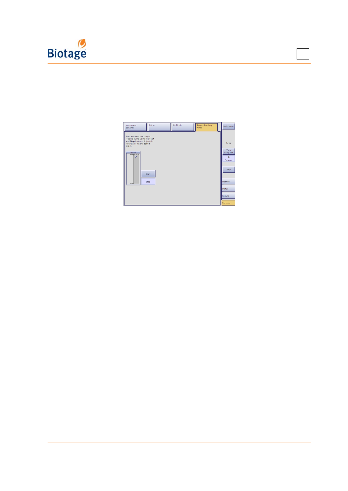
5
3. Select the Solvents tab in the right-hand panel (in the software) and then the Sample
Loading Pump tab.
4. To start the pump, press Start. Adjust the flow rate using the Speed slider.
5. After rinsing with solvent, continue flushing the sample loading pump with air for a minimum of
one minute.
6. When you are done, press Stop.
Figure 5-3. Sample Loading Pump Tab
5.8.2 Replace the Sample Loading Pump Tubing
See “Prepare the Sample Loading Pump for a Run (Only Isolera LS)” on page 4-17.
5.9 Sonicate Solvent Inlet Filters
A solvent inlet filter is installed on the end of each solvent inlet line. The solvent inlet filters protect
the pump and cartridges from damage due to particulate contamination. These filters should be
cleaned (sonicated) or replaced every 1000 hours of operation or every 12 months, whichever
comes first (P/N 412720 for Isolera Prime, One, and Four systems and P/N 412628 for Isolera LS
systems). If using a system where the filers are not screwed onto the solvent inlets lines, we
recommend that you replace both the inlet lines and the filters (P/N 413008 for Isolera One and
Isolera Four, and P/N 413017 for Isolera LS, both kits include four inlets lines and four filers).
411829-L, Maintenance April 2012 Page 5-6
Page 92
5.10 Leaks
Follow all generally-accepted lab safety procedures and applicable laws
and regulations.
Always follow local and national safety regulations and the solvent
manufacturer’s safety, handling, storage, and disposal recommendations;
see solvent manufacturer’s MSDS sheets.
Always follow the Principles of Good Laboratory Practice when handling
potentially hazardous substances.
The Isolera system operates using electricity, which can introduce
additional hazards with certain solvents if not properly connected, vented,
or set up with recommended manufacturer approved settings.
Personnel working with or near the Isolera system must wear protective
clothing, safety gear, and eye protection that have been approved by
applicable local and national safety regulations.
Use only tubing, nuts, and ferrules supplied by Biotage.
5
WARNING
5.10.1 Shut Down the System
If a leakage is observed, shut down the system as follows:
1. If the Leak Detected dialog is open, close it by pressing Close.
2. If a purification is in progress, press Stop at the Status tab and then Abort in the Stop dialog.
3. If a prime is in progress, press End Prime at the Solvents tab.
4. If an air flush (started by the user) is in progress, press End Air Flush at the Solvents tab.
The Air Flush feature is not available with Isolera Prime.
5. If using an Isolera Four system, remove any queued purifications at the Status tab by pressing
Remove.
6. Press Main Menu in the right-hand panel.
7. Press Shut Down.
8. When the message It is now safe to turn off the system appears on the screen, turn off the
system. The power switch is located underneath the touch screen.
5.10.2 Internal Leakage
Internal leakage, due to e.g. worn pump seals or tube fittings, is drained through drain ports
underneath the system.
If an internal leakage is observed:
1. Shut down the system as described in section 5.10.1.
2. Disconnect the power cord from the power outlet.
3. Ensure that the leakage is not external; check all tubes and connections for leaks.
4. Contact Biotage 1-Point Support; see contact details on page 7-1.
411829-L, Maintenance April 2012 Page 5-7
Page 93
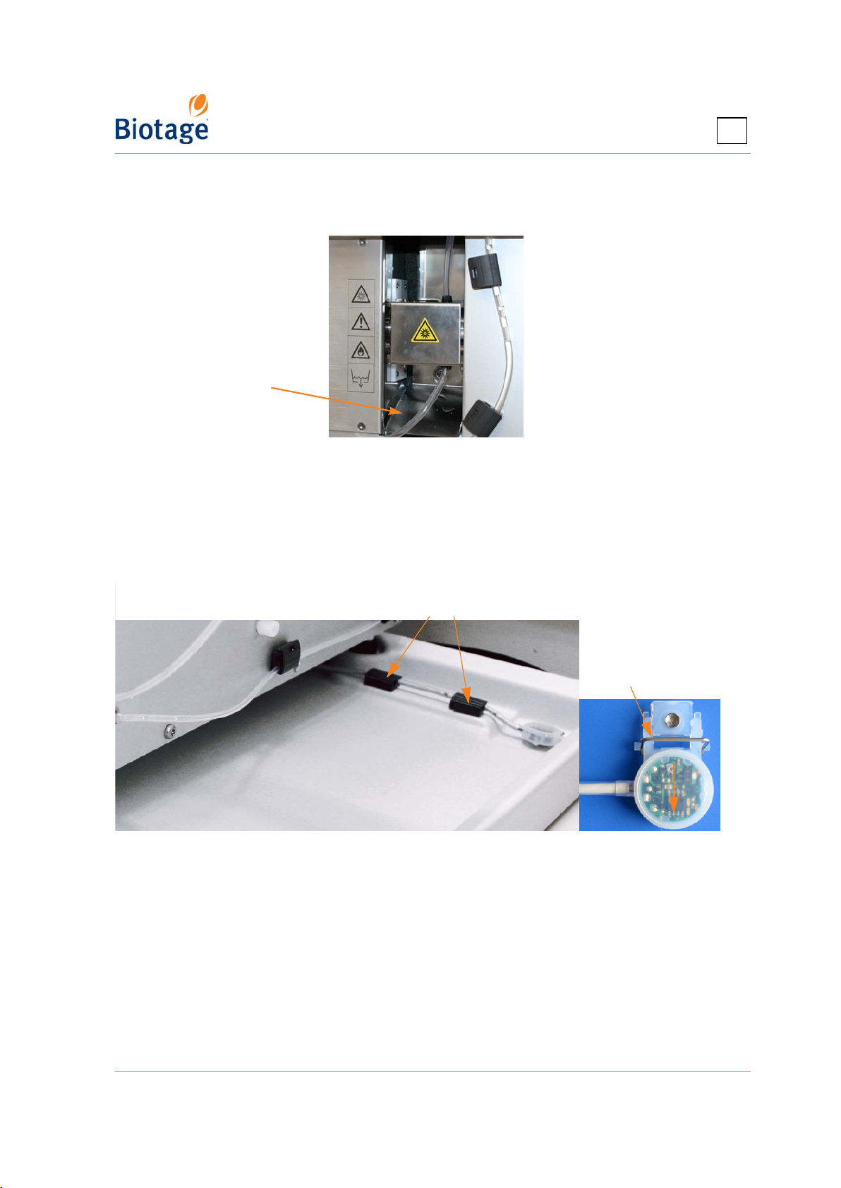
5
5.10.3 External Leakage
External leakage may occur due to e.g. loose fittings or damaged tubing. Any leakage in the
detector flow cell is drained via the drip sheet; see Figure 5-4 on page 5-8.
Drip sheet
Figure 5-4. Drainage of Leakage from the Detector Flow Cell (Isolera LS Shown)
If an external leakage is observed:
1. Shut down the system as described in section 5.10.1.
2. Disconnect the power cord from the power outlet.
3. Remove the spillage using the appropriate safety precautions.
4. If using Biotage Leak Detector, ensure that the leak detector and the leak tray (including the
space underneath the detector) is cleaned and wiped dry.
Unsnap the detector cable here
Open hatch
Leak tray
Figure 5-5. Isolera System with Leak Detector
5. Check all tubes and connections for leaks. Ensure that the tubes are assembled correctly; see
“Assembling Tubes Correctly” on page 5-9. Use caution when tightening fittings to prevent
stripped threads or crushed ferrules. Replace damaged tubing; a list of spare parts is available
at www.biotage.com.
411829-L, Maintenance April 2012 Page 5-8
Page 94
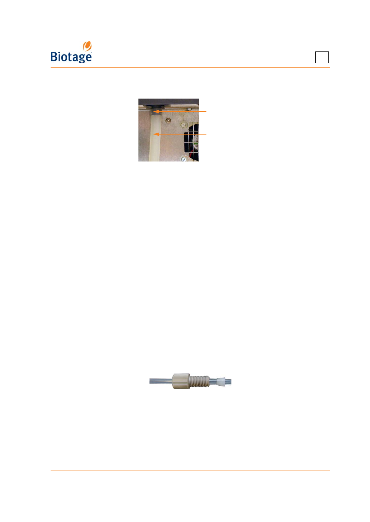
5
6. Ensure that the drain tube for the solvent tray is not damaged and is safely connected to the
Drain port at the rear of the system. The other end shall be inserted into a separate waste
reservoir.
Drain port
Drain tube
Figure 5-6. Drainage of Spillage on the Solvent Tray
WARNING
To avoid being struck by the collection arm, keep your hands out of range
of the collection arm while the homing routine runs in step 7 below.
7. Once you have located and taken care of the leakage, reconnect the system and turn it on. The
collection arm moves through its homing routine and the system boots to the system’s main
menu.
8. Check all tubes and connections for leaks using the prime function; see “Prime the System” on
page 4-33. Prime with water or another suitable solvent.
9. If the problem persists, press End Prime, shut down the system (see page 4-1), disconnect
the power cord from the power outlet, and contact Biotage 1-Point Support (see contact details
on page 7-1).
5.10.4 Assembling Tubes Correctly
WARNING
Shut down the system before replacing any tubing.
Use only tubing, nuts, and ferrules supplied by Biotage.
All external tubing on the Isolera systems except for the tubing inside the collection arm can be
replaced by the user; a list of spare parts is available at www.biotage.com.
If using an Isolera system with flangeless tubing, please notice that proper sealing is only achieved
with the ferrule oriented as shown in Figure 5-7, with the tapered portion of the ferrule facing
toward the nut. The ferrule should be placed near the end of the tube as shown below.
Figure 5-7. Flangeless Tubing with Properly Oriented Ferrule
If using super flangeless tubing, ensure the ferrules are fitted onto the tube ends as described in
the instructions supplied with the ferrules.
When using (super) flangeless tubing, use caution when finger tightening fittings to prevent
stripped threads or crushed ferrules.
411829-L, Maintenance April 2012 Page 5-9
Page 95
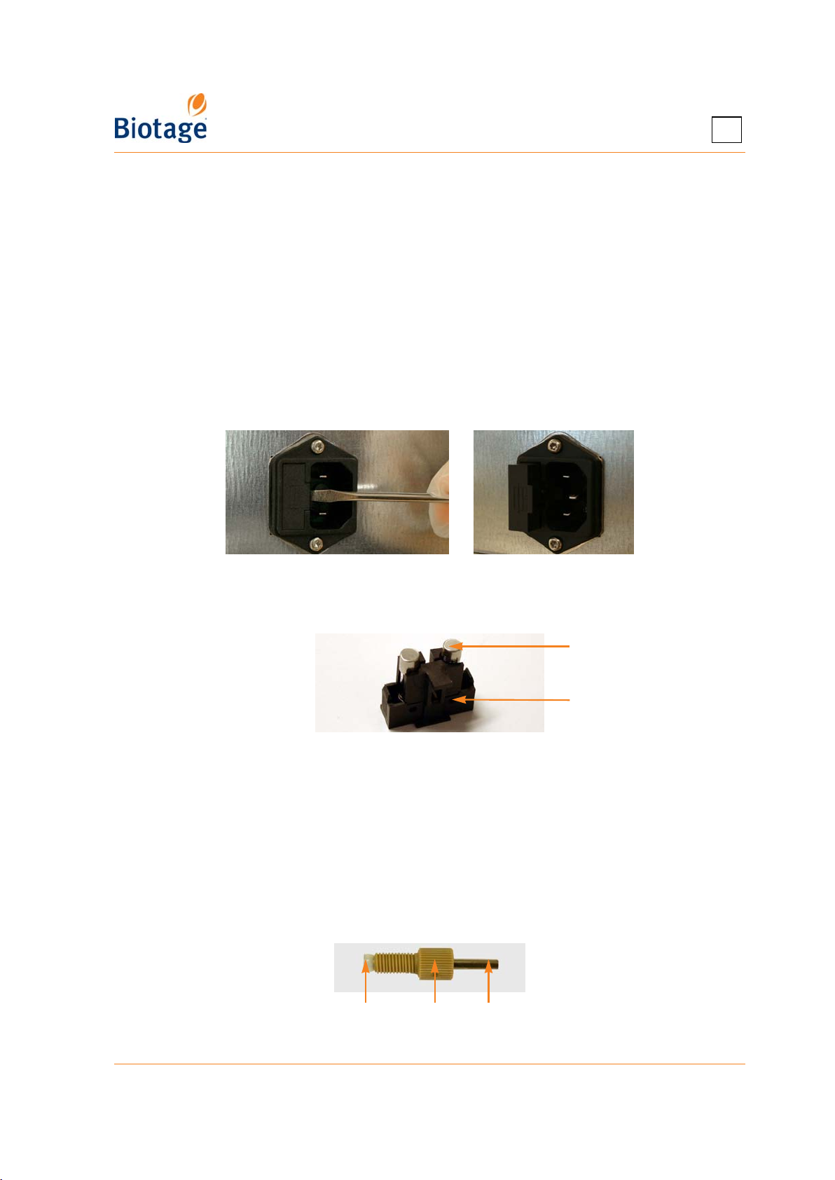
5
5.11 Replace the Fuses
WARNING
The system uses double-pole fusing (both sides of the line are fused). Fire
hazard; always replace with the same type and rate fuses only. If the
system is damaged or does not function properly, contact Biotage 1-Point
Support for repair information (see contact details on page 7-1).
1. Shut down the system as described on page 4-1.
2. Disconnect the power cord from the power outlet.
3. Unplug the power cord from the rear of the system. (You will not be able to remove the fuse
holder if the power cord is plugged in.)
4. Loosen the fuse holder by carefully prying under the notch on the left side of the holder with a
small standard (flat blade) screwdriver; see Figure 5-8.
Figure 5-8. Loosen the Fuse Holder
5. Grasp the fuse holder with your fingers and pull it out of the system.
Fuse
Fuse holder
Figure 5-9. Replace the Fuses
6. Replace the two fuses with new fuses of the same type and rate, 4.0 TA/250 V (P/N 411916).
7. Put the fuse holder back in place.
5.12 Replace the Needle
1. Shut down the system as described on page 4-1.
2. Remove the malfunctioning needle.
3. Assemble the new needle, ferrule, and peek nut (P/N 411915 for Ø1.65 needle and P/N 412616
for Ø3.2 needle). Ensure that the needle is aligned with the end of the ferrule; see Figure 5-10.
NeedlePeak nutFerrule
Figure 5-10. Assemble the Needle, Ferrule, and Nut
411829-L, Maintenance April 2012 Page 5-10
Page 96
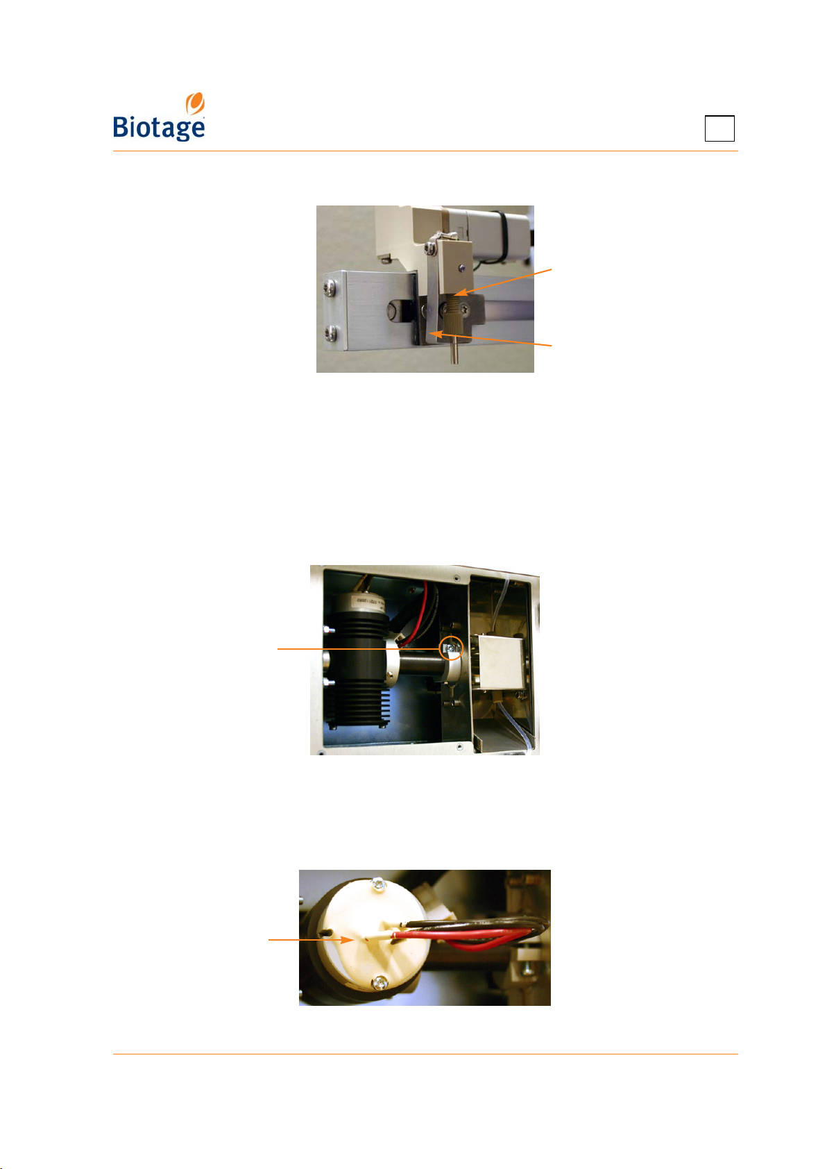
5
4. Mount the needle on the collection arm. Ensure that the needle is touching the needle guide.
Mount the
needle here
The needle
should touch the
needle guide
Figure 5-11. Mount the Needle on the Collection Arm
5.13 Replace the Detector Lamp(s)
1. Shut down the system as described on page 4-1.
2. Disconnect the power cord from the power outlet.
3. Remove the internal detector service panel at the left side of the system using a Torx 10
screwdriver.
4. Loosen the screw locking the UV lamp in a vertical position (see Figure 5-12) using a Torx 20
screwdriver.
Locking screw
Figure 5-12. Loosen the Locking Screw
(Fixed and Variable Detector Shown)
5. Turn the UV lamp into a horizontal position with the lamp socket facing you; see Figure 5-13.
6. Remove the two screws on the lamp socket (see Figure 5-13) using a Torx 10 screwdriver.
Lamp socket
Figure 5-13. Turn the UV Lamp and Remove
411829-L, Maintenance April 2012 Page 5-11
Page 97
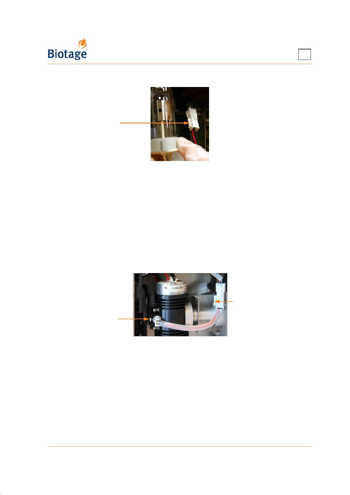
7. Pull out the UV lamp and disconnect it from the power cable; see Figure 5-14.
Press here and
disconnect the
UV lamp
Figure 5-14. Disconnect the UV Lamp
NOTE
Do no touch the UV lamp glass.
8. Mount a new UV lamp (P/N 09830 for all internal Isolera detectors except UV-VIS and P/N
412970 for UV-VIS). Ensure the power cable is positioned so that it does not get in contact with
the fans at the left side of the UV lamp.
9. If using a UV-VIS detector, replace the tungsten lamp (P/N 412970):
a. Loosen the screw holding the tungsten lamp in position using the wrench delivered with
the system.
b. Pull out the tungsten lamp and disconnect it from the power cable; see Figure 5-15.
c. Mount a new tungsten lamp. Ensure the lamp is fully inserted and the power cable is
positioned so that it does not get in contact with the fans at the left side of the UV lamp.
5
Press here
and disconnect
Locking screw
the lamp
Figure 5-15. Disconnect the Tungsten Lamp
10. When you are done, put the service panel back in place.
11. Reconnect the system and turn it on.
12. When the main menu appears, log into the System mode (see page 3-1).
13. Ensure that the detector flow cell is clean (see page 5-3) and then perform an intensity
calibration:
a. Select the Maintenance tab in the right-hand panel.
b. Press Calibrate in the UV Detector field. Read and follow the instructions that appear on
the screen.
411829-L, Maintenance April 2012 Page 5-12
Page 98

Chapter
Troubleshooting
6
WARNING
Before performing any procedures in this chapter, please read and observe
the safety requirements in the “Isolera Installation and Safety” document
(P/N 411828). Failure to follow those requirements may result in personal
injury and/or equipment damage. If the system has been damaged and
does not function properly, shut it down and contact Biotage 1-Point
Support immediately.
6.1 Contact Biotage 1-Point Support
If your problem persists, or for assistance at any time during troubleshooting, contact Biotage
1-Point Support. See contact details on page 7-1.
6.2 Accessories and Spare Parts
A condensed list of accessories is available on page 5-1. For a complete list, please contact you
local representative.
A list of spare parts is available at www.biotage.com.
6.3 Fraction Collector-Related Problems
Problem Possible Causes Solutions
1. The collection arm
does not position
correctly over each
collection vessel.
2. Dripping needle
and/or inconsistent
dispensing
volumes
.
a. Misaligned rack(s). Ensure that the rack(s) is/are aligned correctly.
b. Wrong rack type
selected in the
software.
c. Incorrect rack
parameters. (Only if
using a user-defined
rack type.)
d. The collection arm is
obstructed.
e. Improper calibration
of the collection arm.
Dirty collect valve.
Ensure that you select the correct rack type when
setting up a method; see “Create, Open, and Edit
Methods” on page 4-2.
Ensure that the correct rack parameters have been
entered for the used rack type; see “Administrate
the Rack List” on page 2-5.
Remove any obstacles that obstruct or restrict arm
movement.
Calibrate the collection arm; see “Calibrate the
Fraction Collector” on page 3-13.
Clean the collect valve with methanol or a similar
solvent using the Collect Valve Clean Wizard; see
page 3-13.
411829-L, Troubleshooting April 2012 Page 6-1
Page 99
6.4 Pump-Related Problems
NOTE
If using highly volatile (i.e. high vapor pressure) solvents such as
dichloromethane, reservoir elevation is strongly recommended. Use the
solvent tray at the top of the system. It is also highly advisable to reduce
the flow rate and, if possible, lower the ambient temperature. See “Solvent
Specifications” on page 1-19 for the vapor pressure of different solvents.
Problem Possible Causes Solutions
6
1. Air bubbles moving
through the
cartridge outlet
tubing in a steady
stream during
solvent delivery.
Note that saturation
of a cartridge takes
a minimum of 3 CV.
2. Low or inconsistent
flow delivery volume
and/or
superimposed
periodic detector
signals.
a. Little or no solvent
in the lines.
b. One or more solvent
inlet lines are loose.
c. One or more solvent
inlet filters are
plugged.
a. One or more pump
check valves are not
functioning properly.
b. One or more pump
check valves are not
functioning properly
due to particulates
in the solvent.
c. Solvent vaporization
during refill stroke.
1. Replenish the solvent reservoir(s).
2. Ensure that all used solvent inlet lines are
submerged in solvent; see “Prime the System” on
page 4-33.
Check fittings, loosen, and retighten. If using
flangeless tubing, see “Assembling Tubes Correctly” on
page 5-9. If using super flangeless tubing, ensure that
the ferrules are fitted onto the tube ends as described
in the instructions supplied with the ferrules.
Sonicate or replace the solvent inlet filters; see
page 5-6.
Re-circulating the solvent is not recommended.
Particulate-free solvent is required.
If the problem persists, the pump piston seals or the
check valve seals may be worn. Please contact Biotage
1-Point Support; see contact details on page 7-1.
1. Flush the pump check valves with methanol or a
similar solvent using the Check Valves Release
Wizard; see page 3-14.
2. Check for leaks in the tubing or fittings; see “Leaks”
on page 5-7.
3. If the problem persists, the pump piston seals or
the check valve seals may be worn. Please contact
Biotage 1-Point Support; see contact details on
page 7-1.
1. Flush the pump check valves with methanol or a
similar solvent using the Check Valves Release
Wizard; see page 3-14.
2. If the problem persists, please contact Biotage
1-Point Support (see page 7-1).
1. Elevate the solvent reservoir(s); use the solvent
tray.
2. If possible, lower the ambient temperature.
3. Sonicate or replace the solvent inlet filters; see
page 5-6.
4. Reduce the fill rate for the used solvents (in the
Data Administration mode). Note that Max Fill
Rate parameter can only be changed for userdefined solvents. If using a pre-defined solvent,
make a copy of it and then change the fill rate.
411829-L, Troubleshooting April 2012 Page 6-2
Page 100
Problem Possible Causes Solutions
6
3. The pump does not
deliver solvent.
a. No or insufficient
solvent in the
reservoir(s).
b. Stuck pump check
valve(s).
c. Blockage in solvent
line(s).
d. Leakage. Check for leaks in the tubing or fittings; see “Leaks” on
1. Replenish the solvent reservoir(s).
2. Ensure that all used solvent inlet lines are
submerged in solvent; see “Prime the System” on
page 4-33.
Flush the pump check valves with methanol or a similar
solvent using the Check Valves Release Wizard; see
page 3-14.
1. Sonicate or replace the solvent inlet filters; see
page 5-6.
2. Flush the entire system with methanol or
isopropanol at a low flow rate; see “Prime the
System” on page 4-33.
page 5-7.
6.5 Internal Detector-Related Problems
Problem Possible Causes Solutions
1. Noise. a. Dirty flow cell. Clean the flow cell; see page 5-3.
b. Flow cell incorrectly
inserted.
2. Drifting baseline. a. Dirty flow cell. Clean the flow cell; see page 5-3.
b. Solvent is high-
absorbing at the
selected
wavelength(s).
c. Lamp(s) is/are
defective.
3. Missing peaks when
using baseline
correction.
4. The UV Detector
Failure dialog
appears during auto
or manual UV Zero.
Solvent(s) are highabsorbing over a wide
range of wavelengths.
a. Dirty flow cell. Clean the flow cell; see page 5-3.
b. Highly absorbing
solvent(s).
c. Sample in the flow
cell.
Open the retaining latch and turn the flow cell upside
down.
Change the collection and fractionation wavelength(s)
or turn the Baseline Correction option on (if using a
system with a Spektra license installed).
Replace the lamp(s) and recalibrate the internal
detector; see page 5-11.
Note: If the UV lamp has been used for more than
2000 hours, the message The detector lamp has been
used for x hours and should be replaced appears at
start up.
If expected peaks do not show when you have the
Baseline Correction option turned on and are using
solvents that are high-absorbing over a wide range of
wavelengths (e.g. acetone, and toluene), try
performing the run without baseline correction.
Choose less absorbing solvent(s).
Retry performing the UV Zero when there is no sample
in the flow cell.
If the problem persists, please contact Biotage 1-Point
Support (see page 7-1).
411829-L, Troubleshooting April 2012 Page 6-3
 Loading...