

Page 1
Reference Manual
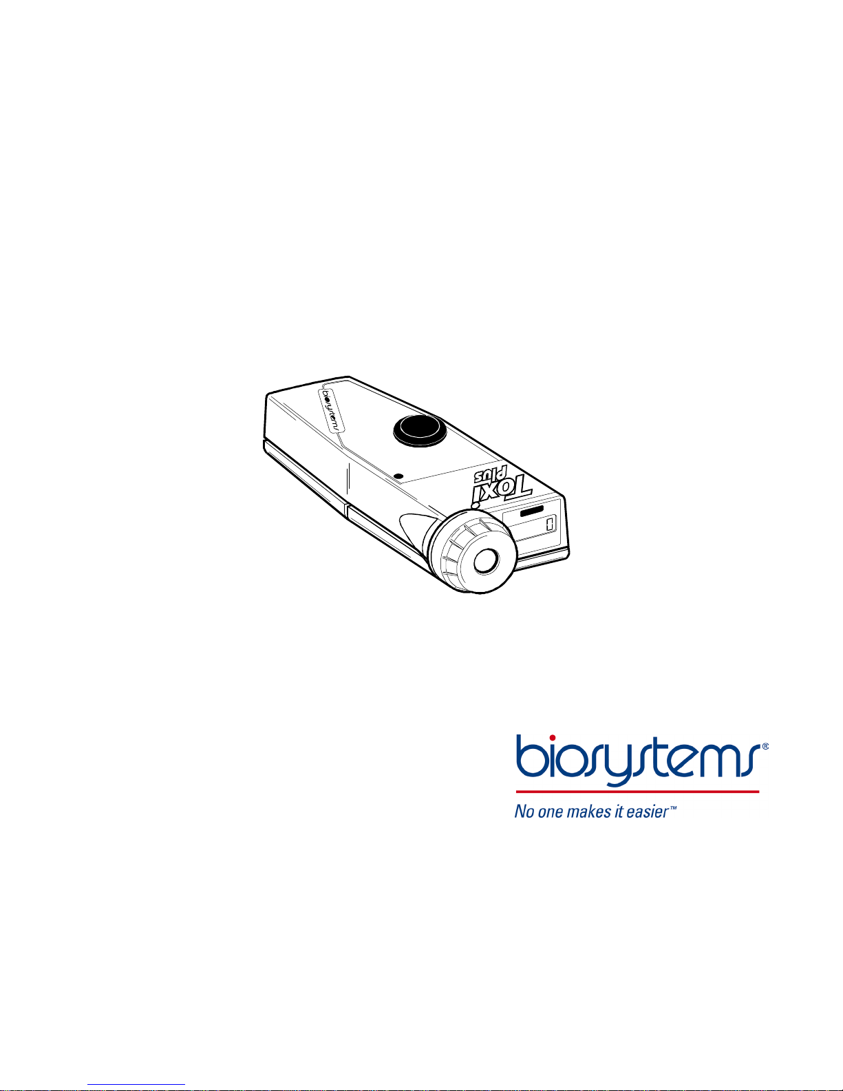
Toxi Plus
Single Sensor Gas Detector
651 South Main St.
Middletown, CT 06457
860-344-1079
FAX 860-344-1068
04AUG2004
P/N: 13-044 Version 3.3
0
Page 2

1
Page 3

THE TOXI PLUS PERSONAL PORTABLE GAS
DETECTOR HAS BEEN DESIGNED FOR THE
DETECTION AND MEASUREMENT OF POTENTIALLY
HAZARDOUS ATMOSPHERIC CONDITIONS
IN ORDER TO ASSURE THAT THE USER IS
PROPERLY WARNED OF POTENTIALLY
DANGEROUS CONDITIONS, IT IS ESSENTIAL THAT
THE INSTRUCTIONS IN THIS MANUAL BE READ,
FULLY UNDERSTOOD, AND FOLLOWED.
AVERTISSEMENT: LIRE ATTENTIVEMENT LES
INSTRUCTIONS AVANT DE METTRE EN MARCHE.
651 South Main St., Middletown, Connecticut 06457
No page or part of this operation manual may be reproduced in any form
without written permission of the copyright owner shown above.
Toxi Plus Operation Manual
Copyright 2004
by
Biosystems LLC
All rights reserved.
2
Page 4

Table of Contents
Introduction 5
Warnings and Cautions ................................................................................... 6
A. Signal Words ................................................................................... 6
B. Warnings ......................................................................................... 6
Chapter 1 Toxi Plus Description 8
1.1 Toxi Plus capabilities ....................................................................... 8
1.2 Methods of sampling ....................................................................... 8
1.3 Sensor options................................................................................. 8
1.3.1 Electrochemical toxic sensors............................................................................. 8
1.4 One Button Auto Calibration............................................................ 8
1.5 Display backlight.............................................................................. 9
1.6 Alarm logic....................................................................................... 9
1.6.1 Atmospheric hazard alarms ................................................................................ 9
1.6.2 Low battery alarms.............................................................................................. 9
1.7 Special microprocessor features ................................................... 10
1.8 Classification for intrinsic safety .................................................... 10
1.9 Options .......................................................................................... 10
1.9.1 Sensors............................................................................................................. 10
1.9.2 Vibrator alarm ................................................................................................... 10
1.9.3 Remote sample draw assembly ........................................................................ 10
1.9.4 Weather cover .................................................................................................. 10
1.9.5 Training video ................................................................................................... 10
1.10 Toxi Plus design components........................................................ 10
1.11 Toxi Plus accessories.................................................................... 11
Chapter 2 Basic operation 12
2.1 Overview of Toxi Plus operation.................................................... 12
2.1.1 Operational warnings and cautions................................................................... 12
2.1.2 Turning the Toxi Plus on ................................................................................... 12
2.1.3 Turning the Toxi Plus off ................................................................................... 12
2.1.4 Start-up sequence............................................................................................. 12
2.2 Operating modes ........................................................................... 12
2.2.1 Text Only mode................................................................................................. 12
2.2.2 Basic mode ....................................................................................................... 13
2.2.3 Technician mode............................................................................................... 13
2.3 Toxi Plus batteries ......................................................................... 14
2.3.1 Low battery voltage alarms ............................................................................... 14
2.3.2 Battery replacement.......................................................................................... 14
2.4 Methods of sampling ..................................................................... 15
2.4.1 Using the hand aspirated sample draw kit ........................................................ 15
Chapter 3 Calibration 16
3.1 Verification of accuracy.................................................................. 16
3.1.1 Effect of contaminants on Toxi Plus sensors .................................................... 16
3
Page 5

3.1.1.1 Effects of contaminants on toxic gas sensors 16
3.1.1.2 Biosystems “CO Plus” dual purpose carbon monoxide / hydrogen sulfide sensor 17
3.1.1.2.1Relative response of the “CO Plus” sensor to CO and H
S gases 17
2
3.2 Fresh air "zero" calibration............................................................. 18
3.3 Functional (bump) test................................................................... 18
3.4 Auto-calibration.............................................................................. 18
3.4.1 Fresh air "zero" auto-calibration sequence....................................................... 19
3.4.1.1 Reading “Too High” or “Too Low” for zero adjust 19
3.4.2 “Span” auto-calibration sequence ..................................................................... 20
3.5 Manual calibration procedure ........................................................ 20
3.5.1 “Forced” fresh air "zero" through keypad buttons ............................................. 20
Chapter 4 Advanced Functions 23
4.1 Setting alarm levels ....................................................................... 23
4.1.1 Alarm adjustment sequence.............................................................................. 23
4.1.2 “Alarm Latch” command.................................................................................... 24
4.1.3 Restoring the factory default alarm settings...................................................... 24
4.2 Re-setting the calibration gas concentration ................................. 25
4.3 Setting the security beep interval................................................... 26
Chapter 5 Trouble Shooting and Repair 27
5.1 Replacing Toxi Plus sensor ........................................................... 27
5.2 Troubleshooting............................................................................. 27
5.2.1 Unit will not turn on ........................................................................................... 27
5.2.2 Unit will not turn off ........................................................................................... 27
5.2.3 Sensor readings unstable ................................................................................. 27
5.2.4 Display is blank ................................................................................................. 27
5.2.5 No audible alarm............................................................................................... 28
5.2.6 Keypad buttons don't work................................................................................ 28
5.2.7 Can’t make a “One Button” auto zero adjustment (“Too High” or “Too Low” for zero
adjust) 28
5.4 Returning your Toxi Plus to Biosystems for service or repair ........ 28
Appendices 29
Appendix A Toxic gas measurement - Ceilings, TWAs and STELs........ 29
Appendix B How to determine where your alarms should be set ............ 31
Appendix C How to calibrate your Toxi Plus in contaminated air ............ 32
Appendix D Suggested Calibration Gases .............................................. 32
Appendix E Cross Sensitivity Data .......................................................... 33
Appendix F Toxi Plus sensor ranges....................................................... 33
Appendix G: Biosystems Standard Warranty Gas Detection Products ........ 34
4
Page 6

Introduction
The Toxi Plus is a personal, portable, microprocessor controlled, single sensor gas
detector. The hazard the Toxi Plus is designed to detect is determined by the type of
sensor installed at the time of purchase. The Toxi Plus may be configured for the
detection of carbon monoxide (CO), hydrogen sulfide (H2S), sulfur dioxide (SO2), or may
be equipped with a dual purpose “CO Plus” sensor for the simultaneous measurement
of both CO and H2S.
The Toxi Plus uses a top-mounted LCD (liquid crystal display) to show readings of the
gas being measured as well as other messages. An audible alarm and alarm light warn
users of hazardous conditions. An optional vibrator type alarm is also available for use
in high noise or other environments requiring additional warnings. A manually
activated display back-light insures that the LCD may be easily read even in dim light
conditions. The Toxi Plus offers a choice of three modes of operation, (“OK”, Basic
and Technician) providing the right amount of information for users with different skill
levels. Biosystems’ “One Button” operating logic allows all procedures necessary for
normal day-to-day operation, including fully automatic calibration adjustment, through
use of the single on/off “Mode” button.
The Toxi Plus is Classified by Underwriters Laboratories, Inc. and the Canadian
Standards Association (pending) as to Intrinsic Safety for use in Hazardous Locations
Class I, Division 1, Groups A, B, C, and D. Classification for intrinsic safety is based on
tests conducted in explosive gas / air (21 % Oxygen) mixtures only.
WARNING: SUBSTITUTION OF COMPONENTS MAY IMPAIR INTRINSIC SAFETY.
AVERTISSEMENT: LA SUBSTITUTION DE COMPOSANTS PEUT
COMPROMETTRE LA SÉCURITÉ INTRINSÈQUE.
CAUTION: FOR SAFETY REASONS THIS EQUIPMENT MUST BE OPERATED AND
SERVICED BY QUALIFIED PERSONNEL ONLY. READ AND UNDERSTAND THE
INSTRUCTION MANUAL COMPLETELY BEFORE OPERATING OR SERVICING.
ATTENTION: POUR DES RAISONS DE SÉCURITÉ, CET ÉQUIPMENT DOIT ETRE
UTILISÉ, ENTRETENU ET RÉPARÉ UNIQUEMENT PAR UN PERSONNEL QUALIFIÉ.
ÉTUDIER LE MANUEL D'INSTRUCTIONS EN ENTIER AVANT D'UTILISER, 'ENTRETENIR
OU DE RÉPARER L'ÉQUIPMENT.
CAUTION: ANY RAPID UP-SCALE READING FOLLOWED BY A DECLINING OR ERRATIC
READING MAY INDICATE A GAS CONCENTRATION BEYOND UPPER SCALE LIMIT
WHICH MAY BE HAZARDOUS.
Avertissement: Toute lecture rapide et positive, suivie d'une baisse subite au erratique
de la valeur, peut indiquer une concentration de gaz hors gamme de détection qui peut
être dangereuse.
5
Page 7
Warnings and Cautions
A. Signal Words
The following signal words, as defined by ANSI Z535.4-1998, are used in the Toxi PlusOperator’s
Guide.
indicates an imminently hazardous situation which, if not avoided, will result
in death or serious injury.
indicates a potentially hazardous situation which, if not avoided, could result
in death or serious injury.
indicates a potentially hazardous situation, which if not avoided, may result
in moderate or minor injury.
CAUTION
which, if not avoided, may result in property damage.
used without the safety alert symbol indicates a potentially hazardous situation
B. Warnings
1. The Toxi Plus personal, portable gas detector has been designed for the
detection of specific toxic gas accumulations. An alarm condition indicates the presence of a
potentially life-threatening hazard and should be taken very seriously.
2.
procedures. The safest course of action is to immediately leave the affected area, and to return only
after further testing determines that the area is once again safe for entry. Failure to immediately
leave the area may result in serious injury or death.
3.
long as the bulb is being squeezed.
4.
known concentration calibration gas. Failure to check accuracy can lead to inaccurate and
potentially dangerous readings.
5.
replaced immediately. An instrument equipped with a sensor that fails calibration may not be used
until testing with known concentration test gas determines that accuracy has been restored, and the
instrument is once again fit for use.
6.
unless the concentration of your calibration gas differs from the concentration of the calibration gas
that is normally supplied by Biosystems for use in calibrating the Toxi Plus.
7.
calibrating the Toxi Plus can lead to dangerously inaccurate readings and may void the standard
Biosystems warranty.
Biosystems offers calibration kits and long-lasting cylinders of test gas specifically developed for
easy calibration. Customers are strongly urged to use only Biosystems calibration materials when
calibrating the Toxi Plus
8.
9.
only. Read, understand and follow the directions set forth in this reference manual before operating
the Toxi Plus.
10.
O2) Only.
In the event of an alarm condition it is important to follow established
Hand aspirated remote sampling only provides continuous gas readings as
The accuracy of Toxi Plus instruments should be checked periodically with
A sensor that cannot be calibrated or is found to be out of tolerance must be
Do not reset the calibration gas concentration setpoints in the Toxi Plus
Use of non-standard calibration gas and/or calibration kit components when
Substitution of components may impair intrinsic safety.
For safety reasons the Toxi Plus must be operated by qualified personnel
The Toxi Plus has been tested for intrinsic safety in Explosive Gas/AIR(21.0%
6
Page 8

7
Page 9

Chapter 1 Toxi Plus
Description
1.1 Toxi Plus capabilities
The Toxi Plus gas detector can be
customized to meet specific customer
requirements. This chapter discusses
some of these special features as well as
basic capabilities used on a day-to-day
basis.
1.2 Methods of sampling
The Toxi Plus may be used as either a
"Diffusion" or "Sample-Draw" type
monitoring device.
In normal operation, the Toxi Plus detector
is worn on the belt, clipped into the user's
shirt pocket, suspended on the neck
lanyard, or held in the hand. Once turned
on, the Toxi Plus monitors continuously.
The atmosphere reaches the sensor by
diffusing through a dust and water-resistant
protective filter directly into the sensor.
Normal air movements are enough to carry
the sample to the sensor. The sensor
reacts to changes in the concentration of
the hazard being measured. Values are
constantly updated and displayed on the
Toxi Plus LCD.
This type of "diffusion" operation monitors
only the atmosphere that immediately
surrounds the detector.
It is possible to use a sample draw kit to
obtain readings from remote locations with
a hand-operated squeeze-bulb, which is
used to draw the sample in through a probe
assembly and a length of hose back to the
instrument. Use of the sample draw kit is
covered in section 2.4.
1.3 Sensor options
The Toxi Plus can be configured to monitor
for any one of several different atmospheric
hazards. The hazard the Toxi Plus is
designed to detect is determined by the
sensor. The type of sensor must be
specified at the time the instrument is
purchased. The types of sensors currently
available include substance-specific
electrochemical sensors for the detection of
carbon monoxide (CO), hydrogen sulfide
(H2S), and sulfur dioxide (SO2). In addition,
a dual purpose “CO Plus” sensor for the
simultaneous detection of both CO and H2S
is also available for occasions when a
single sensor detector must be used to
monitor for the presence of multiple
hazards.
Toxic gas readings are given in PPM (parts
per million) concentrations.
1.3.1 Electrochemical toxic
sensors
The Toxi Plus uses highly specific,
electrochemical toxic sensors that have
been designed to minimize the effects of
common interfering gases. Biosystems
uses substance specific sensors to provide
accurate, dependable readings for carbon
monoxide (CO), hydrogen sulfide (H2S),
and sulfur dioxide (SO2). In addition to
these substance specific sensors,
Biosystems also offers the “CO Plus”
electrochemical sensor. The CO Plus
sensor is a dual purpose sensor designed
to simultaneously respond to both to CO
and H2S.
Contact Biosystems for additional
information concerning the
appropriateness of the “CO Plus”
sensor for specific applications.
1.4 One Button Auto Calibration
The Toxi Plus detector has been designed
for easy verification of accuracy.
Biosystems’ “One Button” logic means that
all normal day-to-day operating
procedures, including automatic calibration
adjustment, can be made with the on/off
MODE button.
Accuracy of the Toxi
Plus should be checked periodically
with known concentration calibration
8
Page 10

gas. Failure to check accuracy can lead
to inaccurate and potentially dangerous
readings.
Calibration is a two step procedure. In the
first step the Toxi Plus is taken to an area
where the atmosphere is fresh and a "zero"
adjustment is made. The second step of
the calibration procedure is the sensor
response or "span" adjustment. In this
step the toxic sensor is exposed to known
concentration calibration gas. If the
instrument notes there is a deviation from
the expected response, it will automatically
adjust itself so that the readings match the
concentration of the gas being used.
Calibration procedures are discussed in
detail in Chapter 3.
1.5 Display backlight
A manually activated display backlight
allows the LCD to be read in dim light
conditions. Pressing the on/off MODE
button once at any time during normal
operation causes the backlight to be
activated for 10 seconds. In the event of a
gas alarm the backlight turns on
automatically and remains on until the
alarm condition clears.
1.6 Alarm logic
Toxi Plus alarms are user adjustable and
may be set anywhere within the range of
the sensor. When an alarm set point is
exceeded a two-toned audible alarm
sounds, a bright red LED alarm light
flashes, and (if equipped) the optional
vibrator type alarm is activated.
Toxi Plus alarms are normally selfresetting. When readings drop back below
the pre-set alarm levels, the instrument
returns to normal operation, and the visual
and audible alarms cease.
Toxi Plus alarms may also be set so that
they "latch." With the alarms latched, once
an alarm occurs both visual and audible
alarms continue to sound even after the
atmospheric hazard has cleared. The
instrument must be manually reset to
silence the alarms.
Procedures for latching Toxi Plus alarms
are given in Chapter 4.
1.6.1 Atmospheric hazard
alarms
The Toxi Plus personal,
portable gas detector has been
designed for the detection of dangerous
atmospheric conditions. An alarm
condition indicates the presence of a
potentially life-threatening hazard and
should be taken very seriously.
In the event of an alarm
condition it is important to follow
established procedures. The safest
course of action is to immediately leave
the affected area, and to return only after
further testing determines that the area
is once again safe for entry. Failure to
immediately leave the area may result in
serious injury or death.
Three alarm set-points have been provided
for Toxi Plus detectors: TWA (Time
Weighted Average), STEL (Short Term
Exposure Limit), and Ceiling. Toxi Plus
alarm settings are set at the factory in the
most conservative way possible.
The procedures for adjusting alarm set
points or restoring the factory default
settings are given in Chapter 4.
1.6.2 Low battery alarms
The Toxi Plus uses 3 AAA alkaline
batteries for power. A fresh set of batteries
should provide up to 1,500 hours of normal
operation.
When it is time to replace the batteries a
"B" will appear in the lower left hand corner
of the display screen, and the audible
alarm will “beep” once per minute until the
battery is replaced. The user should have
approximately one to two weeks of useful
life remaining. Batteries should be
replaced as soon as possible after any low
battery message is displayed.
9
Page 11

See section 2.3 of this manual for
battery replacement procedures.
1.7 Special microprocessor
features
Several automatic programs prevent
tampering and misuse of the Toxi Plus.
Each time the detector is turned on, an
electronic self-test is performed. The
sensor, LED alarm light, and audible alarm
are automatically evaluated, and the
battery is monitored continuously for proper
voltage.
Optional setup choices include adding a
security beep, latching the alarms,
changing the concentration of the gas that
is used during Auto Calibration adjustment,
as well as changing or restoring the factory
alarm settings by using the 4 push-buttons
on the instrument keypad.
Chapter 4 describes advanced technical
features and setup choices in detail.
1.9.2 Vibrator alarm
An internally mounted vibrating alarm is
optionally available for use in high noise or
other environments requiring additional
warnings. The vibrator alarm option must
be specified at the time the instrument is
purchased.
1.9.3 Remote sample draw
assembly
An optional hand aspirated (squeeze bulb)
sample draw kit is available for use in
situations where the sample must be
obtained from remote locations. The
sample draw kit consists of a sample draw
adaptor, squeeze bulb, sample probe
assembly, spare filters, and 10 feet of
sample tubing.
1.9.4 Weather cover
An optional leather weather cover is
available for use in environmentally harsh
locations, or where additional protection is
desired.
1.8 Classification for intrinsic
safety
The Toxi Plus is Classified by
Underwriters Laboratories, Inc., and the
Canadian Standards Association
(pending) as to Intrinsic Safety for use in
Hazardous Locations Class I, Division 1,
Groups A, B, C, & D.
Classification for intrinsic safety is
based on tests conducted in explosive
gas / air (21 % Oxygen) mixtures only.
1.9 Options
1.9.1 Sensors
Toxi Plus detectors may be configured for
the detection of carbon monoxide (CO),
hydrogen sulfide (H2S), sulfur dioxide (SO2),
or equipped with a “CO Plus” sensor for the
simultaneous measurement of both CO and
H2S. The sensor selected must be
specified at the time of purchase.
1.9.5 Training video
A comprehensive 25-minute training video
is available to augment and support the
written Owner’s Manual.
1.10 Toxi Plus design components
(1) Case: The instrument is enclosed in a
durable, gasketed case constructed of a
metal plated ABS / polycarbonate material.
(2) LCD display: A top mounted liquid
crystal display (LCD) meter allows display
of readings, messages, and other
information. A manually activated backlight insures that the LCD may be easily
read even in dim light conditions.
(3) Alarm light: A bright red top-mounted
LED (light emitting diode) alarm light
visually warns users when an alarm level is
exceeded.
(4) Audible alarm: A loud two-toned
audible alarm is also provided to warn
users of hazardous conditions.
10
Page 12
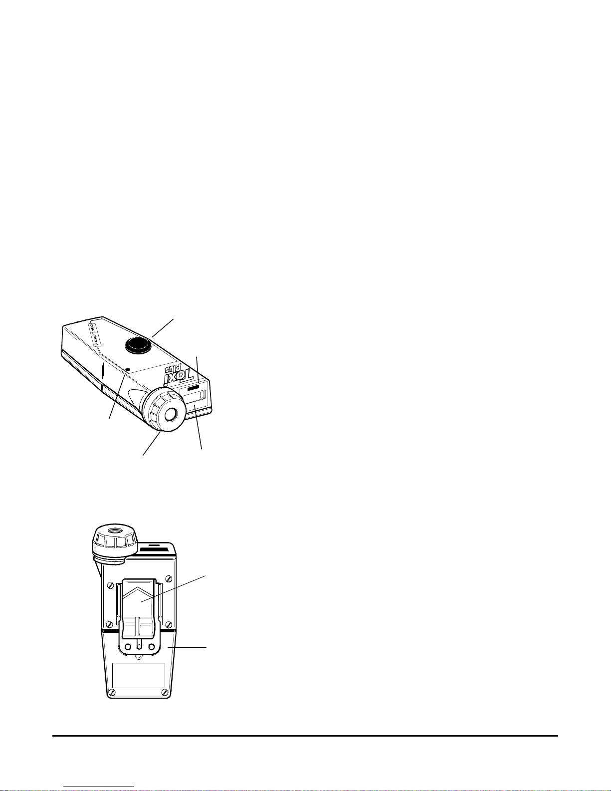
(5) MODE button: The on/off "Mode"
button is used to turn the instrument on and
off as well as control most day-to-day
functions.
(6) Protective cap: A protective O-ring
sealed cap and moisture barrier filter are
protect the sensor from damage.
(7) Sensor: The top-mounted sensor may
be easily accessed for replacement or
repair.
(8) Bottom surface: The stainless steel
belt clip may be removed to allow access to
the 4 hidden push-buttons ("CAL", "ALM",
"+" and "-") used to control advanced
functions.
One button controls all normal
day-to-day operations including
Auto Calibration adjustment
Bright LED alarm
light
1.11 Toxi Plus accessories
Toxi Plus detectors are shipped complete
with sensor, set of three AAA alkaline
batteries (installed), calibration adaptor,
owner’s manual and quick reference card.
Optional Toxi Plus accessories include
sample draw kit, weather cover, training
video, and internally mounted vibrator
alarm (vibrator option must be specified at
time of purchase).
Optional built-in
vibrator alarm for
high noise
environments
Loud two-tone
audible alarm
Accurate
electrochemical
sensor
Easy to read LCD
display with backlight
Figure 1.1: Toxi Plus external features
Belt clip
Battery
compartment
cover
Figure 1.2: Toxi Plus bottom surface
11
Page 13
Chapter 2 Basic operation
2.1 Overview of Toxi Plus
operation
(Note: The software version installed may
differ with that shown above.) The second
shows the type of sensor installed:
The Toxi Plus offers a choice of three
modes of operation, "Text Only," "Basic,"
and "Technician”. Operating mode
selection should be based on how much
information is required, the skill level of the
user, and the nature of the job.
2.1.1 Operational warnings and
cautions
The full list of operational warnings and
cautions are contained at the front of
this manual immediately preceding
chapter 1.
2.1.2 Turning the Toxi Plus on
The black switch on the top of the Toxi Plus
case is called the MODE button. It is used
to turn the Toxi Plus on and off, as well as
to control most other operations of the
instrument. Press and hold the MODE
button for one second to turn the Toxi Plus
on.
2.1.3 Turning the Toxi Plus off
Turn the Toxi Plus off by pressing and
holding the MODE button down for 3
seconds.
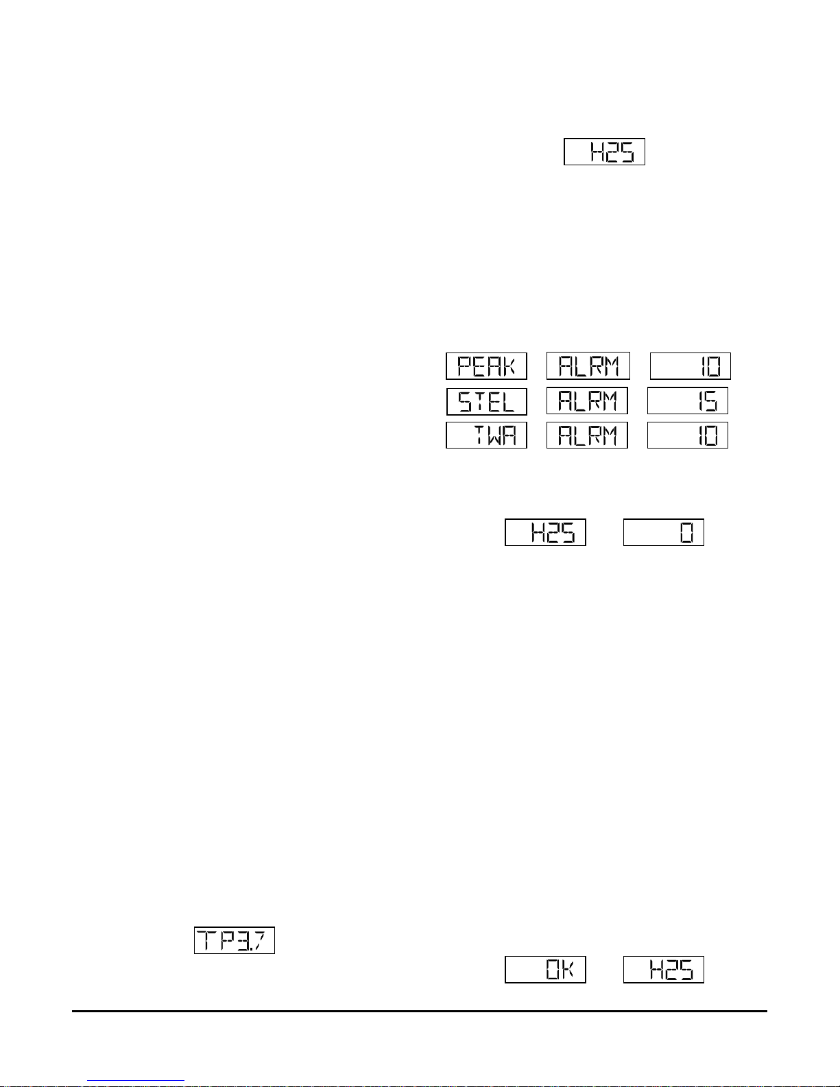
Additional screens will briefly appear
indicating the current Peak, STEL, and
TWA alarm set-points. For instance, a
hydrogen sulfide Toxi Plus with default
alarm settings being operated in the
Technician mode would show the following
sequence of factory installed (default)
alarm set points when the instrument is first
turned on:
→ → →
→ → →
→ →
The current gas reading screen for the gas
being measured will then be shown
alternating with the sensor identifier screen.
↔
Note: The alarm set-point screens are
omitted when the instrument is turned on
while in the "Basic" or "Text Only" modes.
In “Text Only” mode, “OK” will be shown
unless an alarm condition is present.
2.1.4 Start-up sequence
After the detector has been turned on, it will
automatically go through an electronic self
test and start up sequence that takes
approximately twenty seconds. During the
self test sequence the LCD backlight will be
activated, the visual LED alarm light will
flash, the audible alarm will sound, and (if
equipped) the optional vibrator alarm will
briefly activate. During start-up the LCD
display will also show several messages or
"screens" in sequence. The first screen
displays the software version number:
2.2 Operating modes
Three operating modes provide Toxi Plus
users with the right amount of information
to meet their monitoring needs. The Toxi
Plus is designed to be as simple or as
sophisticated as the job that needs to be
done.
2.2.1 Text Only mode
The simplest mode of operation is the "Text
Only" mode. In this mode, during normal
operation the LCD screen does not display
numerical readings, only the indication
"OK". This screen alternates with the
sensor identifier screen.
↔
12
Page 14
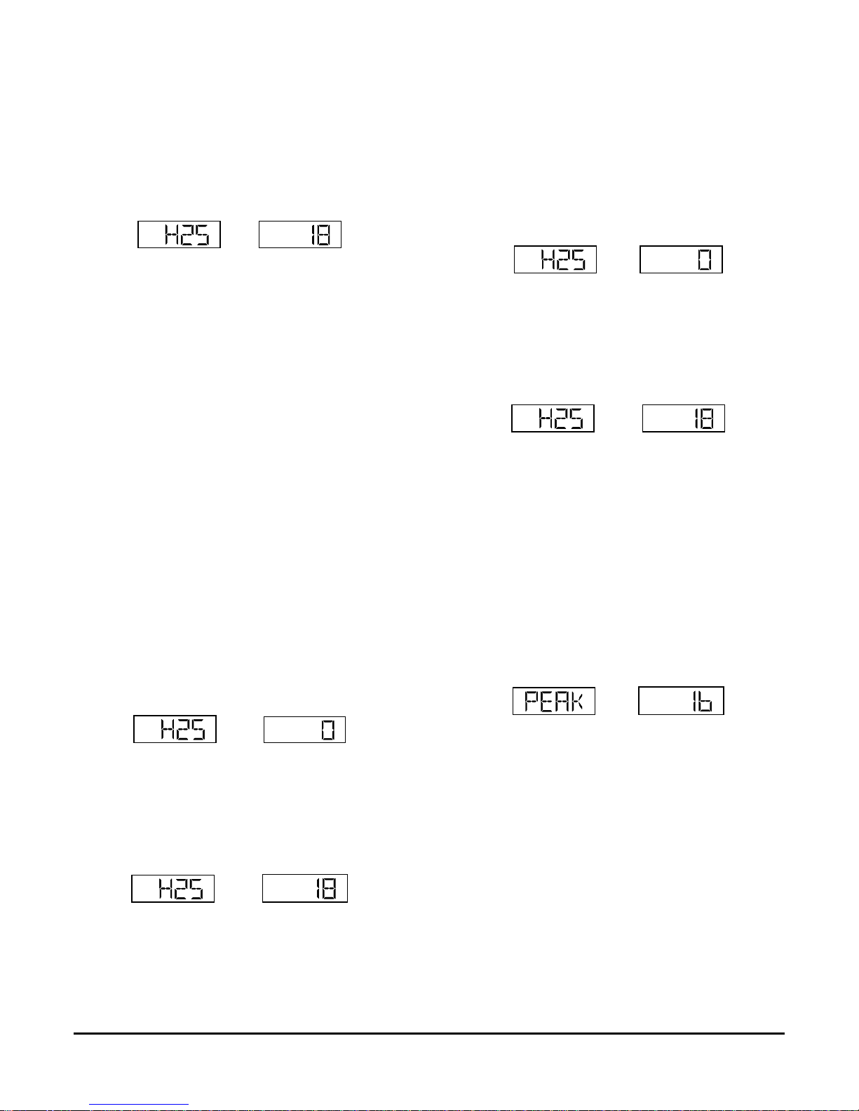
If an alarm condition occurs, that is, when
the sensor readings exceed a pre-set alarm
level, the indication changes from "OK" to
the numerical value, the LED alarm light
flashes, the audible alarm sounds, and (if
equipped) the optional vibrator alarm is
activated.
↔
Toxi Plus alarms are normally selfresetting. When readings drop back below
the pre-set alarm levels, the screen reverts
to the "OK" indication, and visual and
audible alarms cease.
2.2.2 Basic mode
The "Basic" mode of operation is designed
for users with a higher level of
understanding, and a need for numerical
readings, but who are not experts in gas
detection.
In the Basic mode, as in the “Text Only”
mode, the user has access to only one
"screen" of information; the current gas
readings. The major difference between
the two modes is that in the Basic mode
numerical gas level readings are always
provided, whereas in the Text Only mode
only an indication that conditions are "OK"
is provided unless the instrument is in
alarm.
2.2.3 Technician mode
"Technician Mode" provides access to all
advanced functions and displays. When
the instrument is turned on in the
Technician Mode, following the completion
of the start-up and self-test sequence, the
meter display will show numeric readings
for the gas being measured.
↔
An alarm condition occurs when sensor
readings exceed a pre-set alarm level.
During an alarm the numerical reading
changes to reflect the new value, the LED
alarm light flashes, and the audible alarm
sounds.
↔
Toxi Plus alarms are normally selfresetting. When readings drop back below
the pre-set alarm levels, visual and audible
alarms cease, and normal operation of the
instrument resumes.
In Technician Mode, press the MODE
button to scroll through the additional
screens of information. The first screen is
the gas level display discussed above.
Press the MODE button once to display the
peak reading of the gas being measured
since the instrument was switched on.
Basic mode current gas level screen:
↔
An alarm condition occurs when sensor
readings exceed a pre-set alarm level.
During an alarm the numerical reading
changes to reflect the new value, the LED
alarm light flashes, and the audible alarm
sounds.
↔
Toxi Plus alarms are normally selfresetting. When readings drop back below
the pre-set alarm levels, visual and audible
alarms cease, and normal operation of the
instrument resumes.
↔
Press the MODE button again to view the
STEL (Short Term Exposure Level) of the
toxic gas being measured. The STEL
(Short Term Exposure Limit) for a particular
toxic gas is the maximum average
concentration to which an unprotected
worker may be exposed in any 15 minute
interval during the day. The STEL value
displayed is the average concentration for
the most recently completed 15 minutes of
operation.
Since STEL calculations are made using
the most recent fifteen-minute monitoring
interval, it is not possible to compute a toxic
gas STEL until the Toxi Plus has been
13
Page 15
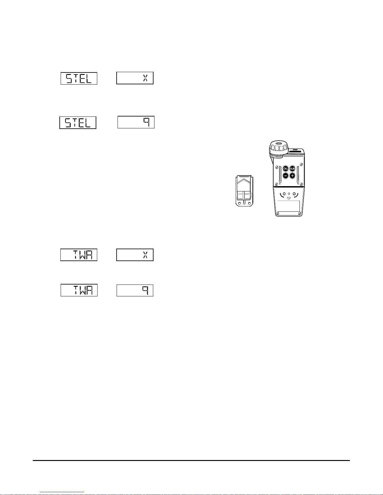
monitoring for at least fifteen minutes. Until
the minimum monitoring time has elapsed,
the STEL screen will show an "X" where
the reading should be.
↔
After fifteen minutes have elapsed, the
STEL screen will show the appropriate
numerical value.
↔
Press the MODE button again to display
TWA (Time Weighted Average) exposure
levels. Time Weighted Average or TWA
values are calculated by taking the sum of
exposure to a particular toxic gas in the
current operating session in terms of partsper-million-hours and dividing by an eighthour period. It is not possible to compute a
toxic gas TWA until the Toxi Plus has been
monitoring for at least one hour. Until the
minimum monitoring time has elapsed, the
TWA screen will show an "X" where the
reading should be.
four mini-push-buttons. Then
simultaneously press and hold the "+" and
"-" buttons until the word “MODE” is
displayed. Each time the operating mode
is changed the display screen will briefly
indicate which operating mode has been
selected.
Note: Shifting modes or otherwise
reprogramming the instrument should
only be done by employees who are
authorized to do so.
Figure 2.2. Toxi Plus with belt clip
removed exposing the four keypad
push-buttons
↔
After an hour has elapsed, the TWA screen
will show the appropriate numerical value.
↔
Pressing the MODE button again to return
current gas readings.
Regardless of operating mode selection,
anytime the Toxi Plus is on, it is
remembering the peak readings of all
gases measured, and is calculating both
long term Time Weighted Averages and
Short Term Exposure Levels (for toxic gas
reading detectors) and will go into alarm
whenever appropriate.
2.2.4 Changing operating modes
It’s possible to change operating modes
while the instrument is in use without
affecting the on-going calculations used to
determine Peak, STEL and TWA alarms.
Simply slide the belt clip at the back of the
instrument out of the way to expose the
2.3 Toxi Plus batteries
The Toxi Plus uses a set of three AAA
disposable alkaline batteries. A fresh set of
batteries should power the instrument for
up to 1,500 hours of operation.
2.3.1 Low battery voltage
alarms
When it is time to replace the batteries a
"B" will appear in the lower left hand corner
of the display screen, and the audible
alarm will “beep” once per minute until the
batteries are replaced. Once the “B” is
shown, the user should have approximately
one to two weeks of useful battery life
remaining.
2.3.2 Battery replacement
Toxi Plus batteries should be replaced as
soon as possible after a low battery ("B”)
message has been noticed.
Use the following procedure to change the
batteries.
14
Page 16

(1) Turn the instrument off.
(2) Remove the belt clip from the bottom of
the instrument by sliding it completely
free of the belt clip mounts.
(3) Loosen and remove the two screws
securing the battery compartment cover
to the instrument case. (The screws
must be completely removed to detach
the battery compartment cover from the
instrument case.)
(4) Gently remove the battery compartment
cover by sliding it backwards then lifting
it free from the instrument case.
(5) Remove the old batteries.
(6) Make sure the battery terminals are
clean.
(7) Install the new batteries. Use high
quality alkaline batteries only. (Make
sure that the batteries are aligned in the
correct directions, and that all battery
polarities are correct.)
(8) Replace the battery compartment cover,
screws, and belt clip.
(9) Accuracy of the Toxi Plus detector
must be verified by exposure to
known concentration test gas before
the instrument is put back into
service.
2.4 Methods of sampling
The Toxi Plus may be used as either a
"Diffusion" or "Sample-Draw" type
monitoring device.
In normal operation, the Toxi Plus detector
is worn on the belt, clipped into a shirt
pocket, suspended from the neck lanyard,
or held by hand. Once turned on, the Toxi
Plus monitors continuously. The
atmosphere being measured gets to the
sensor by diffusing through a protective
moisture barrier filter. Normal air
movements are enough to carry the sample
to the sensor.
The sensor reacts to changes in the
concentration of the gas being measured.
Values are quickly updated and displayed
on the LCD meter. This type of "diffusion"
operation monitors only the atmosphere
that immediately surrounds the detector.
It is possible to use the Toxi Plus to sample
remote locations by using a sample draw
kit. The Toxi Plus kit uses hand-aspirated
squeeze bulb to draw a sample-back to the
instrument through a hose and probe
assembly.
2.4.1 Using the hand aspirated
sample draw kit
(1) Connect the slip-on sample draw cup
with the squeeze bulb and hose
assembly. (Connect the end of the short
length of hose closest to the bulb to the
sample draw cup. Connect the other
end of the hose to the sample probe.)
(2) Cover the end of the sample draw
probe assembly with a finger, and
squeeze the aspirator bulb. If there are
no leaks in the sample draw kit
components, the bulb should stay
deflated for a few seconds.
(3) Insert the end of the sample probe into
the location to be sampled.
(4) Squeeze the aspirator bulb several
times to draw air from the remote
location to the sensor compartment.
Allow one squeeze of the bulb for every
one foot of sampling hose.
Caution: Hand aspirated remote
sampling only provides continuous gas
readings as long as the bulb is being
squeezed.
Each time a reading is desired, it is
necessary to squeeze the bulb a sufficient
number of times to bring a fresh sample to
the sensor.
15
Page 17
Chapter 3 Calibration
The Toxi Plus detector has been
designed for easy calibration. The
MODE button is used to enter the “AutoCalibration” mode, and automatically
make all calibration adjustments. It is
also possible to manually calibrate the
instrument by using simple push-button
controls located on the instrument
keypad.
“One-Button Auto-Cal” procedures
are discussed in Section 3.4. Manual
calibration procedures are discussed
in Section 3.5.
3.1 Verification of accuracy
The accuracy of
Toxi Plus instruments should be
checked periodically with known
concentration calibration gas. Failure
to check accuracy can lead to
inaccurate and potentially dangerous
readings.
Verification of accuracy is a two step
procedure. In the first step the Toxi Plus
is taken to an area where the
atmosphere is fresh and the readings are
checked. If the readings differ from
those expected in fresh air a "zero"
adjustment must be made. The second
step is to make sure the sensor is
accurate by exposing it to known
concentration test gas and noting the
response. Readings are considered
accurate when they are within ±10% of
the expected concentration as given on
the calibration gas cylinder. If readings
are accurate, there is no need to adjust
your gas detector. If the readings are
inaccurate, the instrument must be span
calibrated before further use.
Biosystems offers calibration kits and
long lasting cylinders of test gas
specifically developed for easy Toxi Plus
calibration. Customers are urged to use
Biosystems calibration materials when
calibrating their Toxi Plus detectors.
Use of nonstandard calibration gas and/or
calibration kit components when
calibrating the Toxi Plus can lead to
dangerously inaccurate readings and
may void the standard Biosystems
warranty.
3.1.1 Effect of contaminants
on Toxi Plus sensors
The atmosphere in which the Toxi Plus
monitor is being used can have an effect
on the sensor. Sensors may be
poisoned or suffer degraded
performance if exposed to certain
substances.
The accuracy of
the Toxi Plus should be checked
immediately following any known
exposure to contaminants by testing
with known concentration test gas
before further use.
3.1.1.1 Effects of contaminants on
toxic gas sensors
Biosystems “substance-specific”
electrochemical used to measure CO,
H2S and SO2 have been carefully
designed to minimize the effects of
common interfering gases. “Substancespecific” sensors are designed to
respond only to the gas that they are
supposed to measure. The higher the
specificity of the sensor the less likely
the sensor will be affected by exposure
to other gases which may be incidentally
present. For instance, a “substancespecific” carbon monoxide sensor is
deliberately designed not to respond to
other gases that may be present at the
same time, such as hydrogen sulfide or
methane.
Although great care has been taken to
reduce cross-sensitivity, some interfering
gases may still have an effect on toxic
16
Page 18

sensor readings. In some cases the
interfering effect may be positive and
result in readings that are higher than
actual. In other cases the interference
may be negative and produce readings
that are lower than actual or even result
in negative gas readings.
Cross sensitivity of Toxi Plus toxic
sensors to common interfering gases
is listed in Appendix E.
3.1.1.2 Biosystems “CO Plus” dual
purpose carbon monoxide / hydrogen
sulfide sensor
Carbon monoxide and hydrogen sulfide
are the two most widely occurring toxic
gases found in the industrial workplace.
In addition to “substance specific”
sensors designed to measure these toxic
hazards, Biosystems also offers a dual
purpose sensor designed to
simultaneously detect both carbon
monoxide and hydrogen sulfide. The
“CO Plus” sensor is ideal for situations
requiring use of a single sensor to
monitor simultaneously for both toxic
hazards.
The “CO Plus” sensor has been
designed to respond to both carbon
monoxide and hydrogen sulfide, and can
be calibrated for the direct detection of
either hazard. Since the sensor has
been designed to respond to both
hazards at once, it cannot discriminate
between or tell which of the two gases is
producing the reading. The sensor can’t
tell which hazard is present in what
specific concentrations, but it will go into
alarm if readings exceed the instrument’s
alarm level for a CO or H2S hazard.
Note: When a specific contaminant
such as hydrogen sulfide is known to
be potentially present the best
approach is usually to use a direct
reading substance specific sensor. If
hydrogen sulfide is known to be
potentially present, the sensor
selected should be specifically for the
detection of H2S, and calibrated
directly to this hazard.
Calibration of the CO
Plus sensor with multi-component
calibration gas mixtures containing
both CO and H2S may lead to
inaccurate and potentially dangerous
readings.
Biosystems “CO Plus” sensors are
designed for the simultaneous detection
of both carbon monoxide and hydrogen
sulfide. The calibration gas used to
calibrate “CO Plus” sensors may contain
only one of these two gases. If a “CO
Plus” sensor is calibrated with a mixture
that contains both carbon monoxide and
hydrogen sulfide readings may be
dangerously low.
Biosystems multi-component calibration
gas mixtures which contain both carbon
monoxide and hydrogen sulfide are
labeled as “Not for use with CO Plus
sensors”.
Note: “CO Plus” sensors are normally
calibrated to carbon monoxide. The
calibration gas normally used
contains a mixture of 50 PPM CO.
3.1.1.2.1 Relative response of the “CO
Plus” sensor to CO and H2S gases
A “CO Plus” sensor which has been
properly calibrated to carbon monoxide
will be exactly accurate for the substance
to which it was calibrated. OSHA (1989)
permissible exposure limits for carbon
monoxide specify an 8 hour TWA limit of
35 PPM. If the “CO Plus” sensor is
calibrated to carbon monoxide then
exposed to 35 PPM carbon monoxide the
reading will be 35 PPM.
The “CO Plus” sensor will also show a
“relative response” to other interfering
gases. When calibrated on carbon
monoxide the relative response of the
“CO Plus” sensor to hydrogen sulfide is a
ratio of about 3.5 to 1.0. This means a
17
Page 19

concentration of about 10 PPM hydrogen
sulfide would produce a “CO+” sensor
reading of 10 X 3.5 or 35 PPM.
This is a very convenient relative
response. The 8 hour TWA permissible
exposure limit for hydrogen sulfide is 10
PPM. This means that the “CO+” gas
alarms will be tripped any time the
concentration of hydrogen sulfide
exceeds the permissible exposure limit.
Note: Cross sensitivity of the “CO
Plus” sensor to carbon monoxide,
hydrogen sulfide and other common
interfering gases is listed in Appendix
E.
3.2 Fresh air "zero" calibration
The fresh air "zero" must be done in
fresh, uncontaminated air. In this
procedure the instrument automatically
adjusts its readings to match the
concentrations present in fresh air.
Fresh air contains 0 PPM toxic gas.
If the Toxi Plus cannot be taken to an
area where the air is fresh, or if it is not
certain whether or not the air is
uncontaminated, special procedures are
required. These procedures are
discussed at greater length in Appendix
C.
The second step is to verify the accuracy
of the sensor by exposing it to known
concentration test gas.
3.3 Functional (bump) test
A simple functional (bump) test is all that
is needed to verify accuracy.
To perform a functional (bump) test, turn
the Toxi Plus on, and wait at least three
minutes to allow the readings to fully
stabilize. Make sure the instrument is
located in fresh air. Check to see that
the readings match the concentrations
present in fresh air. If the Toxi Plus is
operated in either the Basic or
Technician mode readings should equal
0 PPM. If the instrument is operated in
the Text Only mode all readings should
indicate conditions are “OK”. If
necessary, fresh air zero the instrument
using the procedures discussed in
Section 3.4.1.
Slip on the calibration adapter as
discussed in Section 3.4.2, and flow
calibration gas to the sensor. Wait for
the readings to stabilize. (Forty-five
seconds to one minute is usually
sufficient.) Note the readings. Readings
are considered accurate when they are
within ±10% of the expected
concentration as given on the calibration
gas cylinder. If readings are accurate,
there is no need to adjust your gas
detector. If the readings are inaccurate,
the instrument must be span calibrated
before further use.
Readings which are more than 10
percent higher or any amount lower
than expected indicate the instrument
must be adjusted using the "span"
calibration procedures discussed in
Section 3.4.2 before further use.
Note: It is necessary to be in either
the Basic or Technician operating
mode in order to make calibration
adjustments. When the instrument is
operated in the Text Only “OK” mode
a functional (bump) test is the
procedure used to verify accuracy. If
the readings are accurate, it is safe to
use the instrument without further
adjustment.
3.4 Auto-calibration
Biosystems “One-Button AutoCalibration” mode may be used to verify
accuracy any time during normal
operation while the instrument is being
used in either the Basic or Technician
operating mode.
Press the MODE button 3 times in rapid
sequence to place the instrument in the
18
Page 20
“Auto-Calibration” mode. Once in the
Auto Calibration mode the adjustments
are made automatically.
Auto-calibration is a two step procedure.
In the first step the Toxi Plus is taken to
an area where the atmosphere is fresh
and a "zero" adjustment is made
automatically by pressing the on / off
MODE button. The second step is the
sensor response or "span" calibration
adjustment. In this step the accuracy of
the Toxi Plus sensor is established by
exposing it to known concentration
calibration gas.
3.4.1 Fresh air "zero" autocalibration sequence
The fresh air zero procedure may only
be done while the instrument is being
operated in either the Technician or
Basic operating mode.
(1) Turn the instrument on and make
sure gas readings are given in
numbers.
If readings are given in the form of
“OK” text messages the instrument is
currently being operated in the “Text
Only” mode. It will be necessary to
change to either the Basic or
Technician operating mode. Switch
modes (if necessary) by
simultaneously holding down the "+"
and"-" keys as discussed in Chapter
2. Each time the operating mode is
changed, the LCD screen will briefly
indicate the current operating mode.
(2) Wait at least three minutes after
turning the instrument on to allow
sensor readings to stabilize fully
before initiating auto-calibration
procedures.
(3) Make sure the instrument is located
in an area where the air is known to
be fresh.
operation, and put it into the “AutoCalibration” mode.
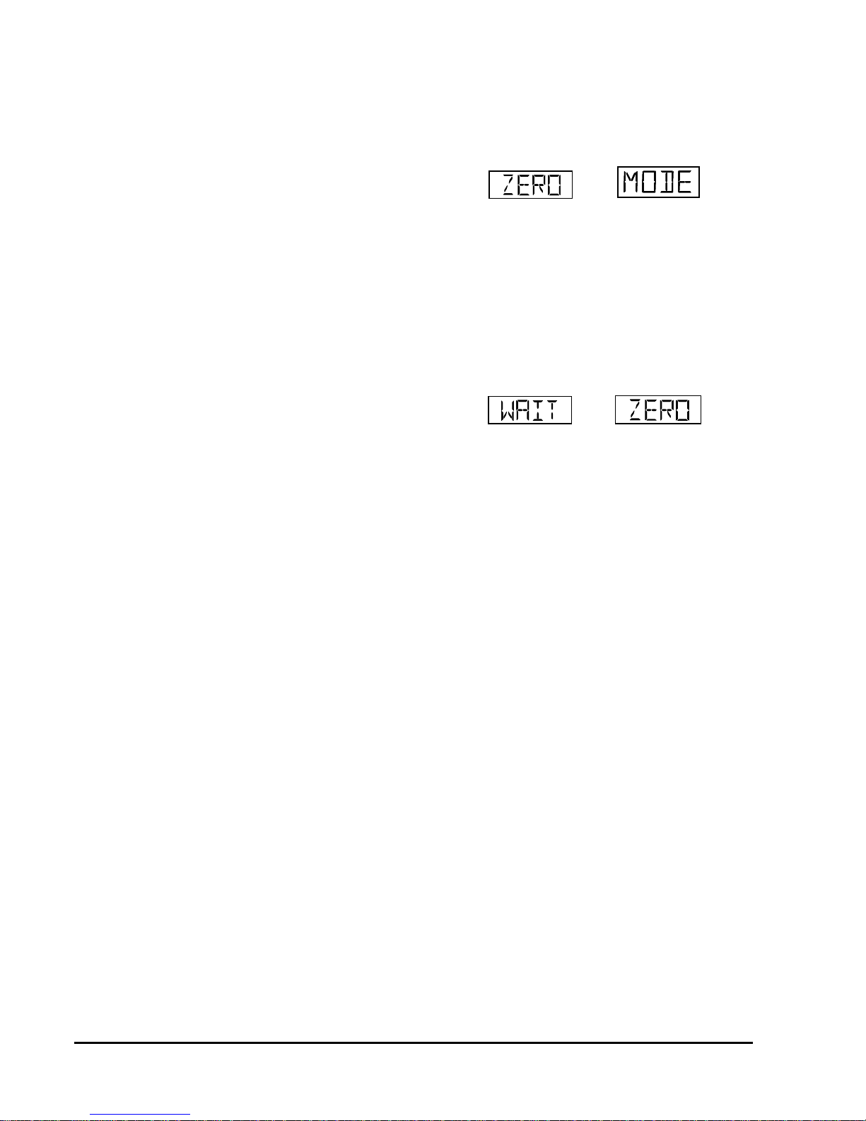
A screen will briefly display the
message “ZERO MODE”.
→
(5) Press the MODE button within five
seconds to initiate the fresh air
adjustment. (If the MODE button is
not pushed within 5 seconds, the
instrument will return to normal
operation.)
The screen will show the message
“WAIT ZERO” while the adjustment is
being completed.
↔
(6) Following successful completion of
the “zero” auto-calibration, the display
will prompt you with the message
“SPAN MODE” to continue with a
span calibration adjustment.
3.4.1.1 Reading “Too High” or “Too
Low” for zero adjust
To reduce the chances of the Toxi Plus
being inadvertently zeroed in
contaminated air, only small adjustments
are allowed through the use of the “One
Button” auto-zero sequence. If the
necessary adjustments are too large the
display will indicate that the reading is
too low or too high for zero adjustment.
In this case the instrument must be fresh
air zeroed using the “Cal” button on the
instrument keypad and procedures
discussed in Section 3.5.1 of this
manual.
Once the instrument has been
successfully zeroed using the “Cal”
button, subsequent calibration
adjustments may be made using the
MODE button and “One Button Auto Cal”
logic discussed in this section.
(4) Press the MODE button 3 times
within two seconds. This will "wake
up" the instrument from normal
19
Page 21
3.4.2 “Span” auto-calibration
sequence
After successful completion of the “zero”
auto-calibration adjustment the display
will show the message “SPAN MODE”.
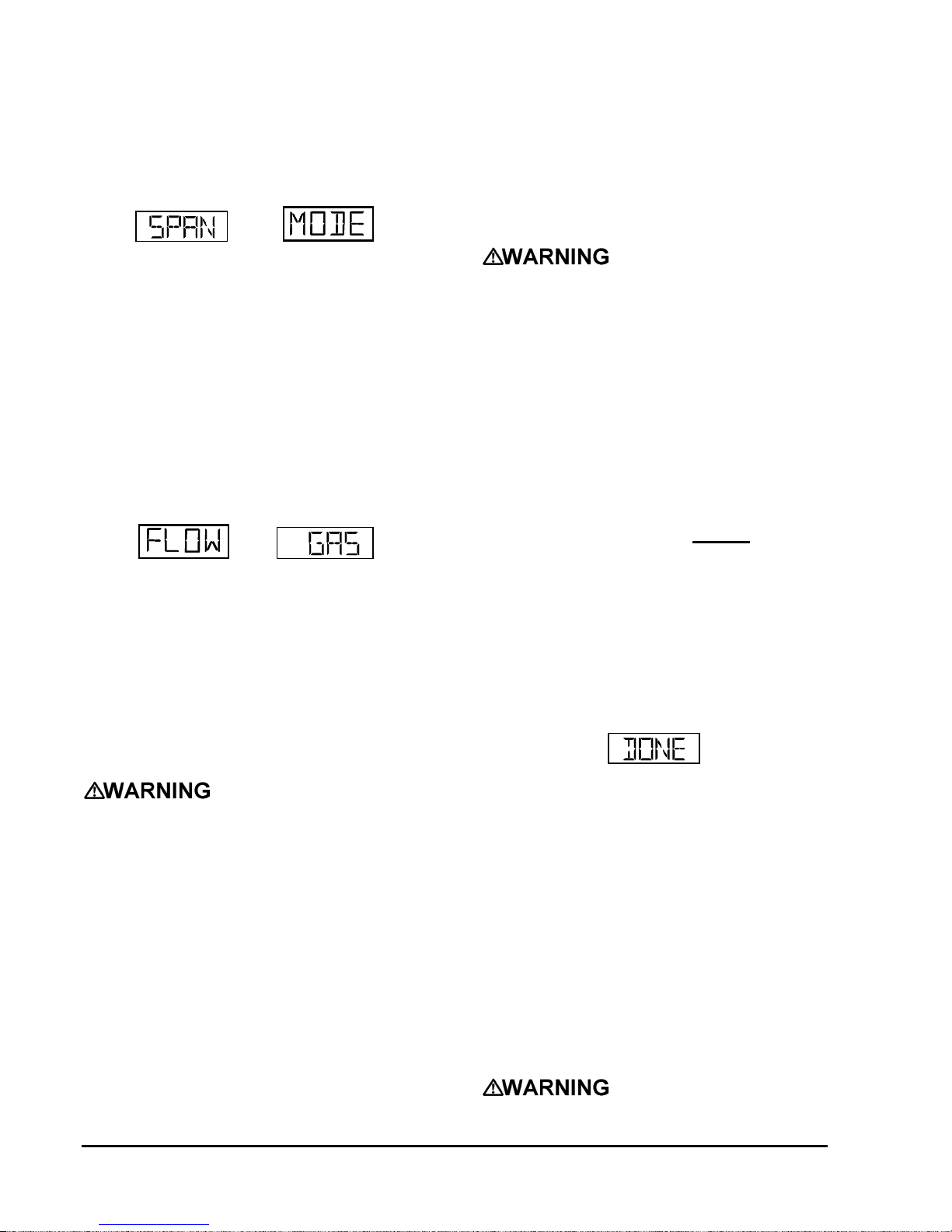
↔
If the MODE button is not pushed within
five seconds a span calibration
adjustment will not be made, and the
instrument will be returned to normal
operation.
(1) Press the MODE button within 5
seconds to initiate “span” autocalibration. A screen will ask you to
“FLOW GAS”. The instrument will
continue to display this screen until it
determines that calibration gas has
been applied.
↔
Note: It is possible to exit the autocalibration mode at any time prior to
completion by pressing and holding
down the MODE button for 3 seconds
to turn the instrument off.
(2) Attach the cylinder of calibration gas,
regulator, short section of tubing and
calibration adapter to the Toxi Plus
detector.
Make sure the
regulator, cylinder seating surfaces
and threads are clean and dry before
attaching the regulator to the cylinder
of gas. Introduction of contaminants
through the regulator fittings may
alter or degrade the concentration of
the gas contained in the cylinder and
may lead to inaccurate and potentially
dangerous gas readings.
The regulator will automatically begin
flowing calibration gas as soon as it is
screwed into the cylinder of gas.
(3) The instrument will display the
sensor readings as they rise. When
they have stabilized at their highest
value, the instrument will note the
response and, if necessary, adjust the
readings to match the concentration of
gas being used to calibrate the
detector. (The instrument will beep as
the adjustment is being made.)
Calibration values
shown on the “Span Adjust” screen
as the sensor is adjusted must match
those appearing on the calibration
gas cylinder(s) that will be used to
calibrate the Toxi Plus. Non-matching
calibration gas and calibration gas
value settings will lead to inaccurate
and potentially dangerous readings.
If the concentration does not match it
will be necessary to assign a new
calibration gas concentration as
discussed in Chapter 4 before
continuing with the auto-span
adjustment.
(4) When span adjustment has been
completed, the display will show the
message “DONE”, after which the
instrument will return to the gas
indicator mode, and display the
current gas readings.
Note: Make sure the calibration
adaptor and all other fittings have
been removed from the detector
before it is returned to service.
3.5 Manual calibration
procedure
It is also possible to calibrate the Toxi
Plus manually using the four buttons on
the instrument keypad.
3.5.1 “Forced” fresh air
"zero" through keypad
buttons
Only perform the
“forced” fresh air calibration in an
atmosphere that is known to be free
20
Page 22
of toxic gases. Performing a “forced”
fresh air calibration in a contaminated
atmosphere will lead to inaccurate
and potentially dangerous readings.
(1) Turn the instrument on.
(2) Wait at least three minutes after
turning the instrument on to allow
sensor readings to stabilize fully
before initiating the fresh air zero
procedure.
(3) Slide the belt clip towards the rear of
the instrument exposing the four
buttons on the instrument keypad.
(4) Verify that the instrument is in the
Basic or Technician operating mode.
Switch modes (if necessary) by
simultaneously holding down the "+"
and"-" keys.
(5) Make sure the instrument is located
in an area where the air is known to
be fresh.
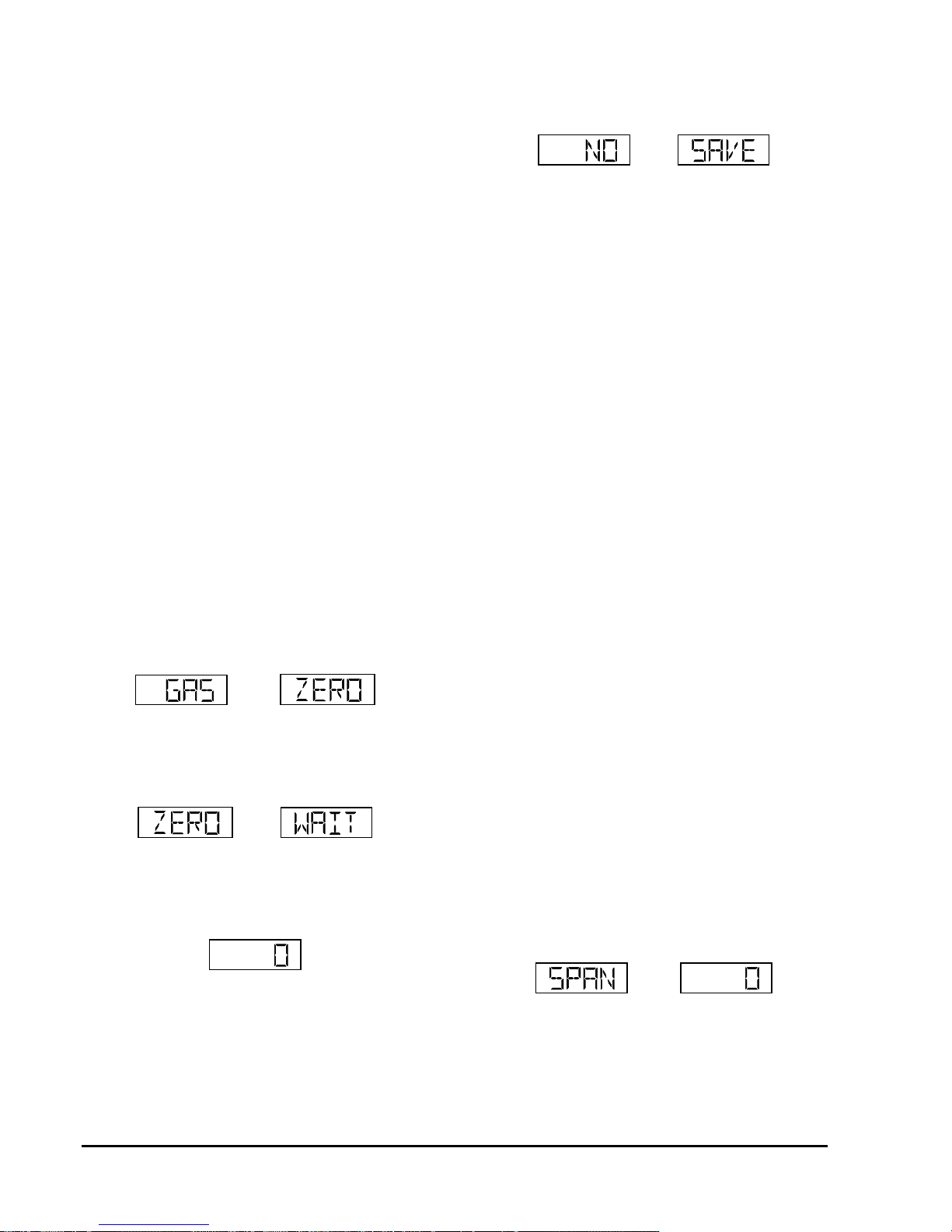
(6) Press the keypad button marked
"Cal". The “GAS ZERO” calibration
message will appear on the instrument
LCD.
↔
(7) Press “Cal” to automatically zero the
instrument. The LCD will show the
message “ZERO WAIT” while the
adjustment is being made.
↔
(8) After completion of the zero
adjustment the Toxi Plus
automatically returns to the gas
reading screen display.
instrument will then return to normal
operation.
↔
3.5.2 Span calibration using keypad
buttons
Span calibration procedures using
buttons on the instrument keypad are
only necessary when the adjustment
necessary to restore accuracy is outside
the permissible window of adjustment for
“One Button Auto Calibration”
procedures. Span calibration using the
keypad buttons may only be done while
in the Basic or Technician operating
mode.
(1) Turn the instrument on.
(2) Remove the belt clip by sliding it free
from the belt clip mounts to expose
the four mini-push-buttons.
(3) Verify that the instrument is in the
Technician or Basic operating mode.
Switch modes (if necessary) by
simultaneously holding down the "+"
and"-" keys. Each time that the
operating mode is changed, the LCD
screen will briefly indicate the current
operating mode.
(4) Turn the instrument off by pressing
the MODE button for three full
seconds.
(5) With the unit turned off, press and
hold down the "Cal" button.
(6) While holding down the "Cal" button,
press the MODE button to turn the Toxi
Plus back on. A screen showing the
message “SPAN” will be displayed which
alternates with the sensor readings.
(9) Pressing the MODE button causes
the calibration values in the memory
to remain unchanged from the last
time a fresh air adjustment was made.
An information screen is displayed
briefly which verifies that the zero
values have not been changed. The
↔
Press and hold the MODE button for
three seconds to cancel the
calibration.
(7) Attach the cylinder of gas, regulator,
short section of tubing and calibration
adaptor to the Toxi Plus. Make sure
21
Page 23
the regulator, cylinder seating
surfaces, and threads are clean and
dry.
(8) The regulator will automatically
begin flowing gas at the correct flow
rate as soon as it is fully screwed in.
When the readings stabilize, use the
"+" and "-" keys to raise or lower the
readings to match the concentration
printed on the calibration cylinder
label.
(9) Make sure the correct cylinder of gas
is attached before attempting to adjust
the span! If the concentration of gas
reaching the sensor is too low to allow
the instrument to be adjusted, or if the
wrong type of gas is applied to the
sensor being adjusted, the alarms will
be activated and a screen will be
displayed indicating that the
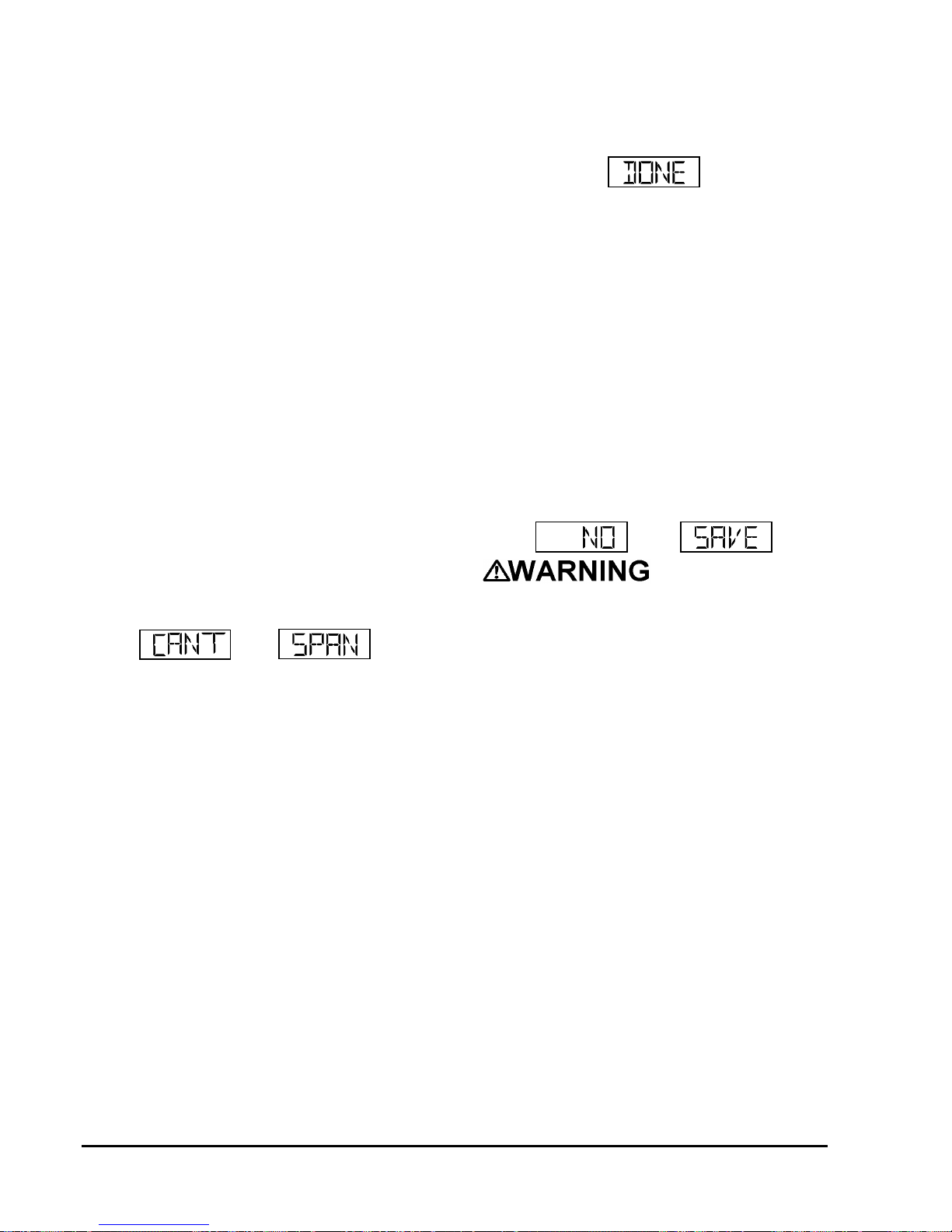
instrument “CANT / SPAN”. Pressing
the MODE button clears the “CANT
SPAN” message and returns the
instrument to normal operation.
↔
In the event that a “CANT SPAN”
message is displayed, verify the type
and concentration of the gas being
used is correct for the sensor being
calibrated, and replace the cylinder if
necessary. Verify that the flow rate of
the regulator is 1.0 liters per minute.
If the "CANT SPAN" message is
repeated it may indicate that the
sensor is unresponsive, or dead, and
requires replacement.
(11) When span calibration has been
completed, press and hold the "Cal"
button down until the LCD screen
indicates that calibration is complete
by showing the message “DONE”.
The Toxi Plus will then turn itself off.
Caution: The “Cal” button must be
held down until the screen indicates
that span calibration has been
successfully completed.
If the button is released before this
message is displayed, span values will
not be updated, and remain unchanged
from the last time a span calibration was
successfully completed.
Pressing the MODE button at any time
cancels the manual span calibration
procedure. A screen will announce “NO
SAVE” after which the instrument will
turn itself off.
↔
A sensor that
cannot be calibrated or is found to be
out of tolerance must be replaced
immediately. An instrument equipped
with a toxic gas sensor that fails
calibration may not be used until
testing with known concentration test
gas determines that accuracy has
been restored, and the instrument is
once again fit for use.
Pressing the MODE button at any time
during the span adjustment cancels the
procedure, and causes the calibration
values in memory to remain unchanged
from the last time a span calibration
adjustment was made.
22
Page 24
Chapter 4 Advanced
Functions
The Toxi Plus microprocessor circuitry
makes possible a number of advanced
features and capabilities. Although
this chapter has been designed
primarily to be of benefit to "experts"
there are several sections that may be
of interest to other Toxi Plus users.
The keypad consists of four mini push
buttons that are located under the
beltclip on the bottom of the detector.
The technique for making advanced
setup changes requires several
buttons to be pressed at the same
time.
Pressing
combinations of buttons not
explicitly covered in this section
may result in unintended changes to
the instrument setup.
4.1 Setting alarm levels
Toxi Plus alarms are user adjustable
and may be set anywhere within the
range of the sensor channel. When an
alarm set point is exceeded a loud
audible alarm sounds, the bright red
LED alarm light blinks, and (if
equipped) the optional vibrator alarm
is activated.
Toxi Plus alarms are normally selfresetting. When readings drop back
below the pre-set alarm levels, visual
and audible alarms cease, and normal
operation of the instrument resumes.
It is possible to set Toxi Plus alarms so
that they "latch." In the latched
condition, once an alarm occurs both
visual and audible alarms continue to
sound even after the atmospheric
hazard has cleared. Press the MODE
button to reset the instrument, silence
the alarms and restore normal
operation. Procedures for latching
Toxi Plus alarms are given in
Section 4.2.
4.1.1 Alarm adjustment
sequence
To change alarm settings, the
instrument must be placed in the
"Alarm Adjust" mode. Once in this
mode, alarm set points may be
adjusted.
In many cases it is possible to comply
with OSHA guidelines while using
higher alarm points than those used by
Biosystems. It is important to note that
the default alarm point settings used in
the Toxi Plus design are very
conservative in order to provide
maximum worker safety.
Toxi Plus default alarm setting are
listed in Appendix B.
To enter the alarm adjust mode:
(1) Turn the instrument on.
(2) Remove the belt clip to expose
the four mini-push-buttons.
(3) Verify that the instrument is in the
Technician operating mode.
Switch modes (if necessary) by
simultaneously holding down the
"+" and"-" keys. Each time that
the operating mode is changed,
the display will briefly indicate the
current operating mode.
(4) Turn the instrument off by
pressing and holding the MODE
button for three full seconds.
(5) With the unit turned off, press and
hold down the "Alarm" button,
then press the MODE button to
turn the Toxi Plus back on.
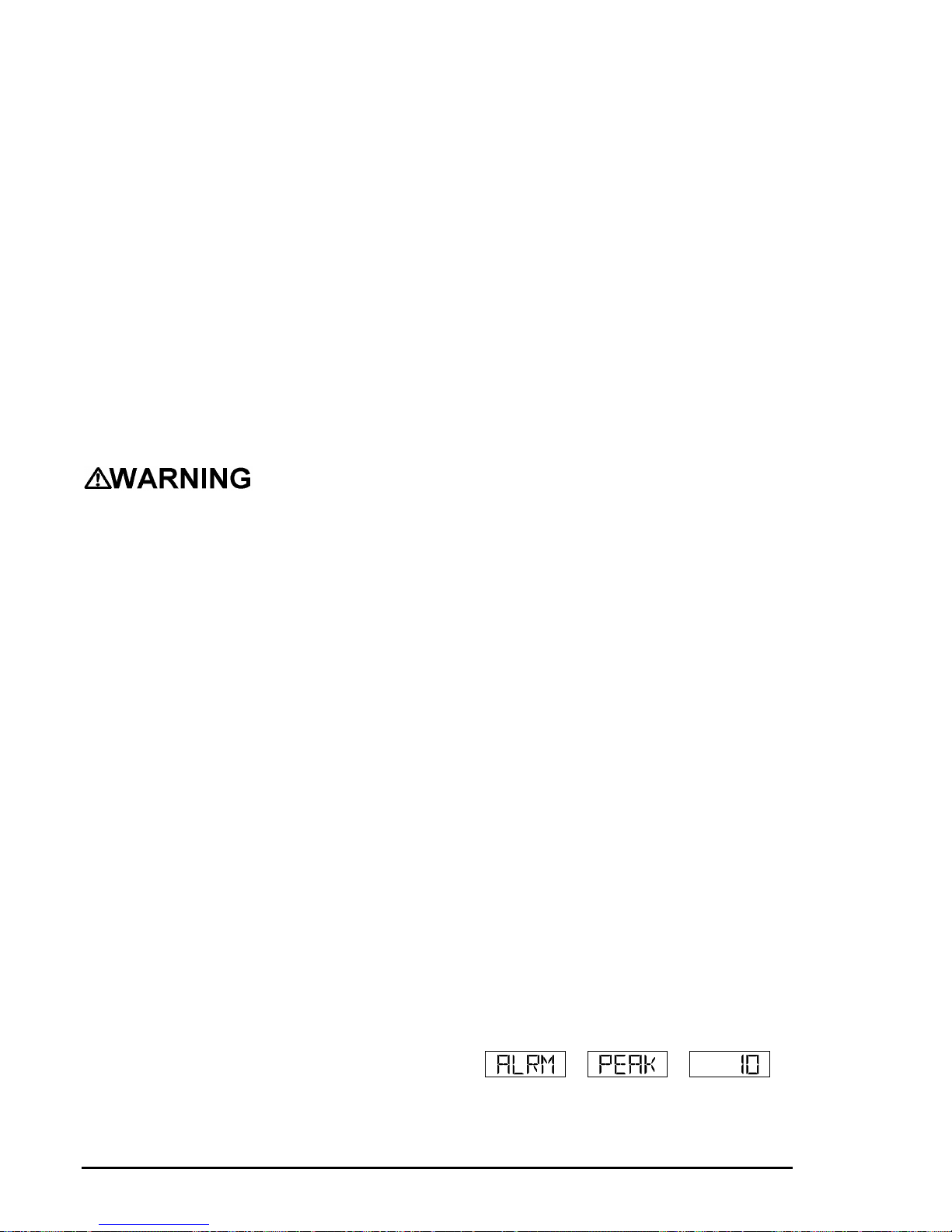
(6) A screen will appear showing the
first alarm point to be adjusted,
and the current alarm set point.
→ →
(7) Press the “Cal” button again to
advance to the next available
23
Page 25

alarm adjustment option. Press
the MODE button at any time to
cancel the alarm adjustment and
return the instrument to the gas
readings screen.
(9) When the desired alarm adjust
option has been reached, the "+"
and "-" keys are used to raise or
lower the alarm set point.
(10) When all alarm adjustments have
been completed, press and hold
the "Alarm" button down until an
information screen indicates that
alarm adjustment is complete.
The instrument will display the “ALRM
LOCK” screen used to latch or lock
Toxi Plus alarms as discussed in
Section 4.2. Press the MODE button
again to turn the Toxi Plus detector off.
4.1.2 “Alarm Latch”
command
Toxi Plus alarms are normally selfresetting. When readings drop back
below the pre-set alarm levels, visual
and audible alarms cease, and normal
operation of the instrument resumes.
It is possible to set Toxi Plus alarms so
that they "latch." In the latched
condition, once an alarm occurs both
visual and audible alarms continue to
sound even after the atmospheric
hazard has cleared. Press the MODE
button to reset the instrument, silence
the alarms and restore normal
operation.
Use the following procedure to “latch”
the Toxi Plus alarms:
(1) Make sure the Toxi Plus detector
is in the Technician mode (as
discussed in Section 2.2.4), then
turn the instrument off.
(2) Turn the instrument on while
pressing and holding down the
“Alarm” button. This will place the
instrument in the “Alarm Adjust
Mode”.
(3) Adjust and save the current alarm
settings, or press mode to exit
without making changes to the
current settings. As the instrument
leaves the “Alarm Adjust Mode” the
unit will display alternating “ALRM
/ LOCK” messages for 4 seconds.
The instrument will then display
the current status of the alarm
latch feature (“ON” or “OFF”).
(4) Use the “+” or “-” key to change
the alarm latch setting.
(5) Once the proper setting has been
selected, press and hold down the
“Alarm” button for three seconds.
Do not release the “Alarm” button
until the LCD displays the
message “DONE” to indicate that
the new setting has been
successfully entered.
Press the MODE button at any
time to cancel the procedure. The
LCD will show the message “NO
SAVE” to indicate that the setting
has not been changed.
4.1.3 Restoring the factory
default alarm settings
Toxi Plus alarm settings are set at the
factory in the most conservative way
possible. (See Appendix B) It is
possible to restore these default
settings at any time by doing the
following.
(1) Turn the instrument on and make
sure it is in the Technician Mode.
(See Section 2.2.4.)
(2) Press the "Alarm" button on the
instrument key-pad. The display
will briefly show the default alarm
message, and the type of sensor
currently installed.
→ →
24
Page 26
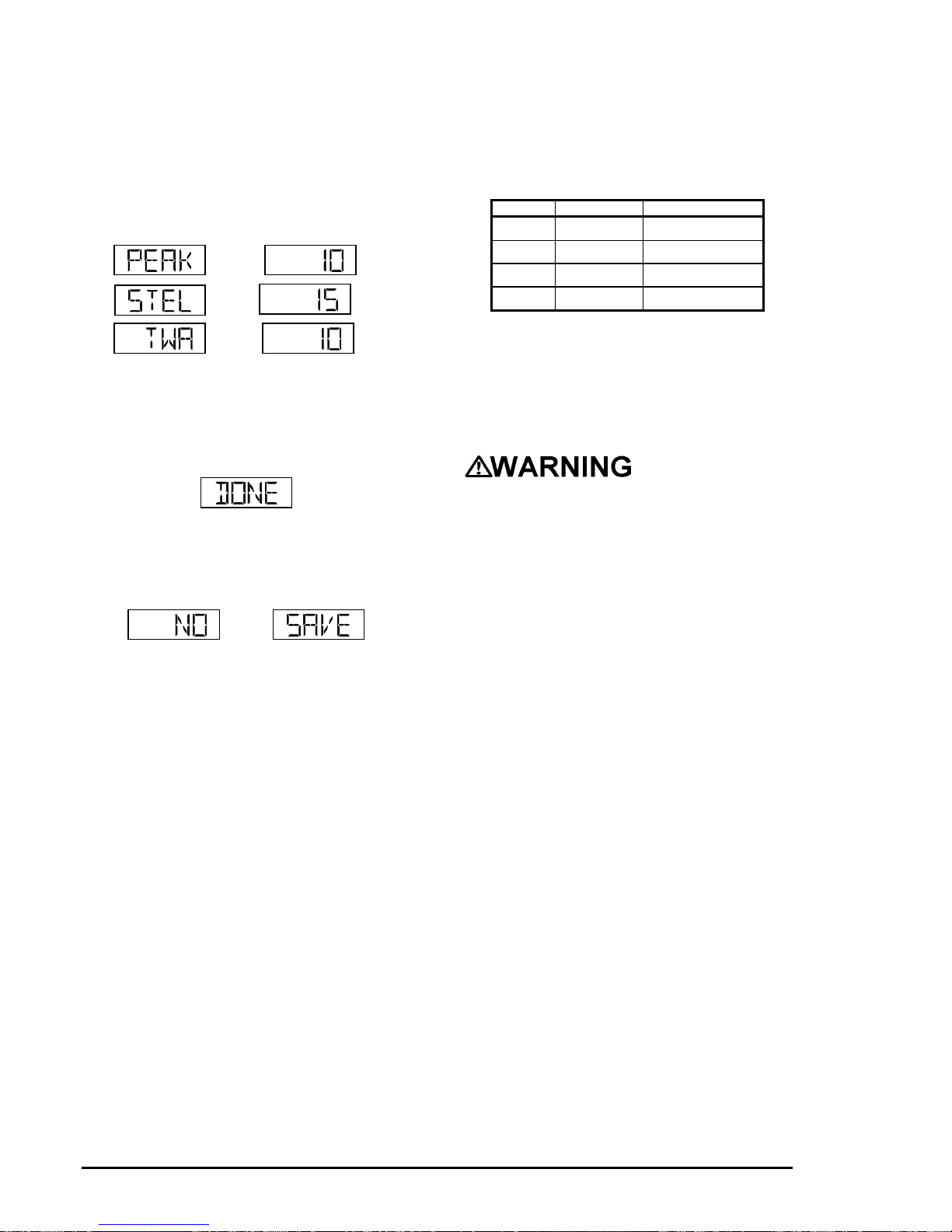
(3) The specific default alarm settings
will then be shown in continuous
rotation. In the case of a Toxi
Plus with a hydrogen sulfide
sensor installed, the following
sequence of screens would be
shown and repeated.
→
→
→
→
→
(5) Push and hold the "Alarm" button
to restore the factory default alarm
settings. The display indicates
when the settings have been
restored:
(6) If the "Mode" button is pushed,
the current alarm settings remain
unchanged, and the display
shows the following screen:
sensor during auto calibration, the
instrument automatically adjusts the
sensitivity of the carbon monoxide to
produce readings that match this 50
PPM concentration.
Sensor Gas Used Concentration
CO CO 50 PPM
CO+ CO 50 PPM
H2SH2S 25 PPM
SO
SO
2
2
10 PPM
Table 5.1. Default Toxi Plus
calibration gas concentrations
It is necessary to re-set the calibration
gas concentration stored in instrument
memory before making use of a
different calibration gas concentration.
Do not reset the
calibration gas concentration unless
you are using a calibration gas
concentration that differs from that
normally supplied by Biosystems
for use in calibrating your
instrument.
↔
(7) After selection of the default or
current alarm settings has been
made, the display returns to the
current gas reading screen.
4.2 Re-setting the calibration
gas concentration
During auto calibration adjustment the
Toxi Plus adjusts the sensitivity of the
sensor to match the concentration of
the gas used to calibrate the sensor.
The value the instrument uses to
adjust the reading is the calibration
gas concentration stored in the
instrument memory.
For instance, Biosystems normally
supplies calibration gas containing 50
PPM carbon monoxide for use in
calibrating CO Toxi Plus detectors.
This is the default calibration gas
concentration stored in the instrument
memory. When gas is applied to the
Customers are strongly urged to
use only Biosystems calibration
materials when calibrating their Toxi
Plus detector. Use of non-standard
calibration gas and/or calibration kit
components can lead to
dangerously inaccurate readings
and may void the standard
Biosystems warranty.
Use the following procedure to re-set
the calibration gas concentration:
(1) Make sure the Toxi Plus detector
is in the Technician mode (as
discussed in Section 2.2.4), then
turn the instrument off.
(2) Turn the instrument on while
pressing and holding down the “+”
button.
The Toxi Plus LCD will display
alternating “CAL” and “GAS”
messages for 4 seconds. The
display will then alternate between
25
Page 27

the current concentration stored in
memory and the “GAS” message
screens.
(4) Use the “+” and “-” buttons to set
the security beep interval (the time
between beeps).
(3) Use the “+” and “-” buttons to
change the concentration.
(4) Once the proper new
concentration has been selected,
press and hold down the “Alarm”
button for three seconds. Do not
release the “Alarm” button until the
LCD displays the message
“DONE” to indicate that the new
value has been successfully
entered.
Pressing the MODE button at any
time cancels the procedure. The
LCD will show the message “NO
SAVE” to indicate that the
calibration gas concentration
values have not been changed.
4.3 Setting the security beep
interval
The interval may be set in
increments of one minute anywhere
between 0 and 60 minutes. Setting
the interval to 0 turns the security
beep back off.
(5) Once the proper setting has been
selected, press and hold down the
“Alarm” button for three seconds.
Do not release the “Alarm” button
until the LCD displays the
message “DONE” to indicate that
the new setting has been
successfully entered.
Pressing the MODE button at any
time cancels the procedure. The
LCD will show the message “NO
SAVE” to indicate that the setting
has not been changed.
The security beep screen allows the
Toxi Plus to be programmed to emit an
audible alarm "beep" on a regular
basis while the instrument is in
operation. This periodic beep serves
as a reminder that the instrument is on.
Use the following procedure to turn the
security beep on:
(1) Make sure the Toxi Plus detector
is in the Technician mode (as
discussed in Section 2.2.4), then
turn the instrument off.
(2) Turn the instrument on while
pressing and holding down the “-”
button.
(3) The Toxi Plus LCD will display
alternating “SEC” and “BEEP”
messages for 4 seconds. The
display will then alternate between
the current security beep interval
in minutes and the message “MIN”.
26
Page 28

Chapter 5 Trouble Shooting
and Repair
5.1 Replacing Toxi Plus sensor
5.2.1 Unit will not turn on
Possible causes:
Battery discharged, microprocessor /
software malfunction.
The Toxi Plus must
be recalibrated before being returned to
service any time the sensor is removed
or replaced.
To replace a sensor:
(1) Make sure the Toxi Plus is turned off.
(2) Gently unscrew (1/4 turn counter
clockwise) and remove the protective
sensor cap.
(3) Gently pry the sensor out of its socket.
(4) Verify that the type of sensor to be
installed matches the label on the
front of the Toxi Plus detector.
(5) Make sure the pins are properly
aligned and gently press the
replacement sensor into place.
(6) Make sure the correct color coded
filter in the protective sensor cap is
replaced along with the new sensor.
(A spare filter should have been
supplied together with the
replacement sensor.) The color of the
filter should match the color of the ID
ring on the upper surface of the
sensor. Use a blunt object to push
the old filter out of the sensor cap,
and using a finger, press the new filter
into place. Be careful not to rip the
filter membrane.
(7) Replace the protective sensor cap.
(8) Allow at least one to two hours for the
sensor to stabilize.
(9) Recalibrate the new sensor.
5.2 Troubleshooting
There are a few troubleshooting and repair
procedures that can be done in the field.
Caution: The following repair
procedures should only be performed by
authorized personnel.
Solution(s):
Take the instrument to a non-hazardous
location. Replace the batteries and
attempt to turn on. (Make sure that the
batteries are properly aligned, and that
all battery polarities are correct.) If the
instrument still fails to turn on, return to
factory for repair.
5.2.2 Unit will not turn off
Possible causes:
Microprocessor / software malfunction,
low or bad battery, faulty on / off mode
switch.
Solution(s):
Take the instrument to a non-hazardous
location, replace the batteries, and
attempt to turn the detector back on. If
the instrument fails to turn on, return to
factory for repair.
5.2.3 Sensor readings unstable
Possible causes:
Loose connection, bad sensor, improper
calibration, expired calibration gas.
Solution(s):
Check that the sensor is firmly in place.
Check calibration gas dating. Recalibrate sensor. Replace sensor if
necessary.
5.2.4 Display is blank
Possible causes:
Battery voltage too low. Operating
temperature too low. Bad LCD display
assembly. Microprocessor locked-up or
"crashed".
Solution(s):
Take the instrument to a non-hazardous
location. If cold, allow instrument to
warm back up to room temperature.
Replace the batteries and attempt to
Page 29

turn the instrument back on. If the
instrument still fails to turn on, return to
factory for repair.
5.2.5 No audible alarm
Possible causes:
Loose connection, alarm failure.
Solution(s):
Return to factory for repair.
5.2.6 Keypad buttons don't
work
Possible causes:
Not in Basic or Technician mode,
microprocessor locked-up or "crashed",
loose connection, switch failure.
Solution(s)
Switch to Technician operating mode.
Take the instrument to a non-hazardous
location. Replace the batteries and
attempt to turn the instrument back on.
If keypad buttons still fail to operate
properly return to factory for repair.
5.2.7 Can’t make a “One
Button” auto zero adjustment
(“Too High” or “Too Low” for
zero adjust)
Possible causes:
The atmosphere in which the instrument
is located is contaminated (or was
contaminated at the time the instrument
was last zeroed); instrument is still
attached to calibration fittings; a new
sensor has just been installed;
instrument has been dropped or banged
since last turned on.
5.4 Returning your Toxi Plus to
Biosystems for service or
repair
Please contact the Biosystems Service
Department at (860) 344-1079 to obtain a
“Return Authorization” number prior to
shipment. A Biosystems Service
representative will record all relevant
information or special instructions at that
time.
To insure safe transport please use the
original Toxi Plus packing materials, or
other packing materials which similarly
protect the instrument and accessories.
Note: The return authorization number
must be clearly marked on the outside of
the box.
Prominently showing the return
authorization number on the outside of the
box ensures that it is immediately identified
and logged into our system at the time it is
received. Proper tracking helps avoid
unnecessary delays in completion of
service procedures.
Please contact the Biosystems Service
Department at (860) 344-1079 or 800 7116776 if you require any additional
information.
Thank you for choosing
the Toxi Plus, and thank
you for choosing
Biosystems.
Solution(s):
Remove any calibration gas fittings,
take the instrument to fresh air and
allow readings to stabilize. Do a
manual fresh air zero adjustment using
buttons on the instrument keypad as
discussed in Section 3.5.1.
28
Page 30

Appendices
Appendix A Toxic gas
measurement - Ceilings, TWAs and
STELs
Many toxic substances are commonly
encountered in industry. The presence of
toxic substances may be due to materials
being stored or used, the work being
performed, or may be generated by natural
processes. Exposure to toxic substances
can produce disease, bodily injury, or death
in unprotected workers.
It is important to determine the amounts of
any toxic materials potentially present in
the workplace. The amounts of toxic
materials potentially present will affect the
procedures and personal protective
equipment which must be used. The safest
course of action is to eliminate or
permanently control hazards through
engineering, workplace controls,
ventilation, or other safety procedures.
Unprotected workers may not be exposed
to levels of toxic contaminants which
exceed Permissible Exposure Limit (PEL)
concentrations. Ongoing monitoring is
necessary to insure that exposure levels
have not changed in a way that requires
the use of different or more rigorous
procedures or equipment.
Airborne toxic substances are typically
classified on the basis of their ability to
produce physiological effects on exposed
workers. Toxic substances tend to produce
symptoms in two time frames.
Higher levels of exposure tend to produce
immediate (acute) effects, while lower
levels of long-term (chronic) exposure may
not produce physiological symptoms for
years.
air produces rapid paralysis of the
respiratory system, cardiac arrest, and
death within minutes.
Carbon monoxide (CO) is a good example
of a chronically toxic gas. Carbon
monoxide bonds to the hemoglobin
molecules in red blood cells. Red blood
cells contaminated with CO are unable to
transport oxygen. Although very high
concentrations of carbon monoxide may be
acutely toxic, and lead to immediate
respiratory arrest or death, it is the long
term physiological effects due to chronic
exposure at lower levels that take the
greatest toll of affected workers. This is the
situation with regards to smokers, parking
garage attendants, or others chronically
exposed to carbon monoxide in the
workplace. Exposure levels are too low to
produce immediate symptoms, but small
repeated doses reduce the oxygen carrying
capacity of the blood over time to
dangerously low levels. This partial
impairment of the blood supply may lead
over time to serious physiological
consequences.
Because prudent monitoring programs must
take both time frames into account, there
are three independent exposure
measurements and alarm types built into
the Toxi Plus design.
1. Ceiling level:
OSHA has assigned some, but not all, toxic
substances with a ceiling level. This is the
highest concentration of a toxic substance
to which an unprotected worker should ever
be exposed, even for a very short time.
Never enter an environment even
momentarily when concentrations of
toxic substances exceed the ceiling
level.
Hydrogen sulfide (H2S) is a good example
of an acutely toxic substance which is
immediately lethal at relatively low
concentrations. Exposure to a 1,000 PPM
(parts per million) concentration of H2S in
29
Page 31
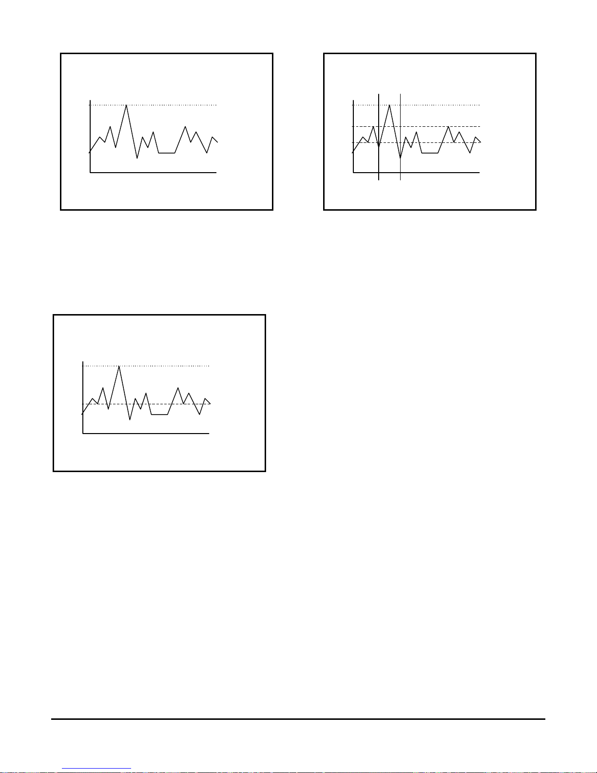
Time History Graph
Time History Graph
Ceiling
2. Time Weighted Average (TWA):
The maximum average concentration to
which an unprotected worker may be
exposed over an eight hour working day.
During this time, STEL and ceiling
concentration limits may not be
exceeded.
Time History Graph
Ceiling
15 Minutes
Ceiling
STEL
TWA
(8 hour)
TWA
3. Short Term Exposure Limits
(STEL):
Toxic substances may have short term
exposure limits which are higher than the
eight hour TWA. The STEL is the
maximum average concentration to which
an unprotected worker may be exposed in
any fifteen minute interval during the day.
During this time, neither the eight hour
TWA or the ceiling concentration may be
exceeded.
Any fifteen minute periods in which the
average STEL concentration exceeds the
permissible eight hour TWA must be
separated from each other by at least one
hour. A maximum of four of these periods
are allowed per eight hour shift.
30
Page 32

Appendix B How to determine
where your alarms should be set
1. Toxic gas alarms
The Toxi Plus has three separate alarm
points for toxic gases: Ceiling, STEL, and
TWA.
OSHA has assigned some, but not all, toxic
substances with a ceiling or "Peak"
exposure level. This is the highest
concentration of a toxic substance to which
an unprotected worker should ever be
exposed, even for a very short time. Never
enter an environment even momentarily
when concentrations of toxic substances
exceed the ceiling level.
The Time Weighted Average ( or TWA) is
the maximum average concentration to
which an unprotected worker may be
exposed over an eight hour working day.
During this time, STEL and ceiling
concentration limits may not be exceeded.
OSHA has assigned some, but not all, toxic
substances with a Short Term Exposure
Limit. The STEL is the maximum average
concentration to which an unprotected
worker may be exposed in any fifteen
minute interval during the day. During this
time, neither the eight hour TWA or the
ceiling concentration may be exceeded.
Any fifteen minute periods in which the
average STEL concentration exceeds the
permissible eight hour TWA must be
separated from each other by at least one
hour. A maximum of four of these periods
are allowed per eight hour shift.
The table below shows the highest levels at
which these alarms should be set. If OSHA
has not determined a ceiling value, for
greatest safety the Toxi Plus ceiling alarm
should be set at the same value as the
STEL alarm. If OSHA has not determined a
STEL value, the Toxi Plus STEL alarm
should be set at the same value as the
TWA.
2. U. S. Department of Labor,
Occupational Safety and Health
Administration (OSHA) Permissible
Exposure Limits for select toxic gases:
In the following table "NA" indicates no
value has been assigned by OSHA.
Note: Customers should be aware that
OSHA permissible exposure limits may
be subject to change.
Recent court decisions have affected
the enforcement of permissible
exposure limits published or modified
since the initial enactment of OSHA in
1971. The following table shows the
OSHA permissible exposure limits as
published in the 1989 edition of the
Code of Federal Regulations (29 CFR
1910.1000). It is recommended that
customers verify that the values given
below are correct and current before
using them to update their alarm setpoints.
OSHA (1989) Permissible Exposure Limits:
Gas Ceiling TWA STEL
CO 200 PPM 35 PPM NA
H2S NA 10 PPM 15 PPM
SO2 NA 2.0 PPM 5.0 PPM
3. Toxi Plus default alarm settings
The most conservative possible way to set
alarms is the method used by Biosystems
for the Toxi Plus default alarm settings.
The Ceiling alarm is set at the factory
at the 8 hour TWA level (when this is
given). With this setting, it is unlikely that
either the STEL or TWA alarm will ever be
activated. For other values, contact
Biosystems or your authorized distributor.
31
Page 33

Biosystems Toxi Plus default alarm
settings:
Gas Ceiling TWA STEL
CO 35 PPM 35 PPM 100 PPM
H2S 10 PPM 10 PPM 15 PPM
SO2 2.0 PPM 2.0 PPM 5.0 PPM
Note: When a “CO Plus” sensor is
installed the default alarm settings are
automatically assigned on the basis of
the calibration gas selected for use. If
carbon monoxide is selected as the
calibration gas, carbon monoxide alarm
settings are automatically assigned. If
hydrogen sulfide is selected as the
calibration gas, hydrogen sulfide alarm
settings are automatically assigned.
Appendix D Suggested
Calibration Gases
Warning: Use of non-standard
calibration gas and / or calibration kit
components when calibrating your Toxi
Plus can lead to dangerously inaccurate
readings and may void the standard
Biosystems warranty.
Biosystems offers calibration kits and
long lasting cylinders of test gas
specifically developed for easy Toxi
Plus
calibration. Customers are strongly
urged to use only Biosystems
calibration materials when calibrating
their Toxi Plus.
Appendix C How to calibrate your
Toxi Plus in contaminated air
Calibration of the Toxi Plus is a two-step
process. The first step is to expose the
sensors to contaminate-free fresh air and
perform a fresh air calibration.
Unfortunately, there are some locations
which are never completely free of
contaminants. An example would be a
furnace intensive area which always has a
background concentration of a few PPM
CO. To make calibration easy in this case,
it is necessary to use special calibration
"Zero Contaminant" gas. This gas cylinder,
Biosystems part number 9039, is used in
conjunction with the sample draw
calibration adapter. Flow the zero
contaminant gas across the sensors for a
minute, just as if you were doing a span
calibration. Then do the fresh air
calibration steps described in Chapter 3 of
the owners manual.
Part
Number
54-9033 Carbon
54-9034 Hydrogen sulfide
54-9037 Sulfur dioxide
54-9039 Zero air (20.9 %
Calibration gas
mixture
monoxide (CO)
(50 PPM in air)
(H2S) (25 PPM
in nitrogen)
(SO2) (10 PPM
in nitrogen)
oxygen in
nitrogen)
Comments
Use for fresh air
calibration in
contaminated areas.
32
Page 34

Appendix E Cross Sensitivity
Data
1
Appendix F Toxi Plus sensor
ranges
The table below lists the cross sensitivity of
electrochemical toxic sensors used in the
Toxi Plus portable gas detectors to gases
other than their target gas. Depending on
the nature of the reaction each gas has
with the sensor, the effect can either
decrease the signal (negative cross
sensitivity) or increase the signal; (positive
cross sensitivity). Each figure represents
the reaction of the sensor to 100 PPM of
gas, thus providing a percentage sensitivity
to that gas relative to its target gas.
SENSOR TYPE
Carbon
monoxi
de (CO)
Hydroge
n sulfide
(H2S)
CO Plus
(Cal to
CO)
CO Plus
(Cal to
H2S)
Sulfur
dioxide
(SO2)
CO 100 < 10 100 25 0
H2S < 10 100 ~ 350 100 0
SO2 < 10 ~ 20 ~ 65 ~ 15 100
NO < 30 < 0 ~ 25 ~ 6 0
NO2 < 15 ~ - 20 ~ - 60 - 15 ~ -
120
Cl2 < 10 ~ - 20 ~ - 40 ~ - 10 < 5
H2 < 60 < 5 < 60 < 15 0
HCN < 15 0 ~ 40 ~ 10 < 50
HCl < 3 0 ~ 5 ~ 1 0
NH3 0 0 0
Ethy
~ 50 0 0
lene
The following tables display the ranges for
currently available sensors for use in the
Toxi Plus. Nominal range values indicate
the gas-level range which the Toxi Plus can
detect over extended periods of operation.
“Max overload” values indicate the highest
instantaneous reading that the Toxi Plus
will be able to attain for a given sensor
type.
Toxic Sensor
Type
Nominal
range (PPM)
Max
overload
CO 0-999 999
H2S 0-100 250
SO2 0-100 250
“CO Plus”
0-999 999
(Cal. to CO)
“CO Plus”
0-50 150
(Cal. to H2S)
1
Data derived in part from City Technology Limited, Product Data
Handbook Oct. 1, 1992
33
Page 35
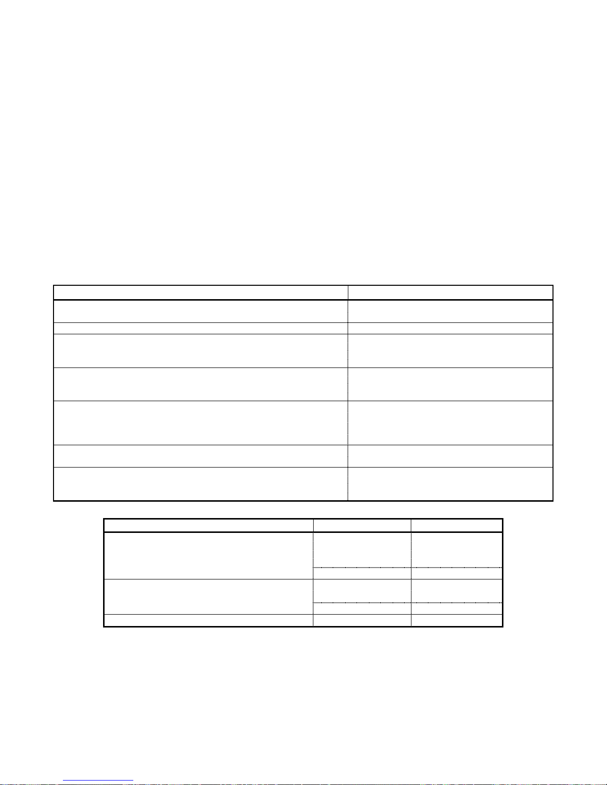
Appendix G: Biosystems Standard Warranty Gas Detection Products
General
Biosystems LLC (hereafter Biosystems) warrants gas detectors, sensors and accessories manufactured and sold by
Biosystems, to be free from defects in materials and workmanship for the periods listed in the tables below.
Damages to any Biosystems products that result from abuse, alteration, power fluctuations including surges and lightning
strikes, incorrect voltage settings, incorrect batteries, or repair procedures not made in accordance with the Instrument’s
Reference Manual are not covered by the Biosystems standard warranty.
The obligation of Biosystems under this warranty is limited to the repair or replacement of components deemed by the
Biosystems Instrument Service Department to have been defective under the scope of this standard warranty. To
receive consideration for warranty repair or replacement procedures, products must be returned with transportation and
shipping charges prepaid to Biosystems at its manufacturing location in Middletown, Connecticut, or to a Biosystems
Authorized W arranty Service Center. It is necessary to obtain a return authorization number from Biosystems prior to
shipment.
THIS WARRANTY IS EXPRESSLY IN LIEU OF ANY AND ALL OTHER WARRANTIES AND REPRESENTATIONS,
EXPRESS OR IMPLIED, INCLUDING BUT NOT LIMITED TO, THE WARRANTY OF FITNESS FOR A PARTICULAR
PURPOSE. BIOSYSTEMS WILL NOT BE LIABLE FOR LOSS OR DAMAGE OF ANY KIND CONNECTED TO THE
USE OF ITS PRODUCTS OR FAILURE OF ITS PRODUCTS TO FUNCTION OR OPERATE PROPERLY.
Instrument & Accessory Warranty Periods
Product(s) Warranty Period
PhD5, PhD Lite, PhD Plus, PhD Ultra Cannonball3, , MultiVision, Ex
Chek, Toxi, Toxi/Oxy Plus, Toxi/Oxy Ultra
Toxi/Oxy Pro 2 years from date of purchase
Toxi/Oxy Limited
Mighty-Tox
Mighty-Tox 2
Prorated credit is given towards repair or purchase of a new unit of
the same type.
IQ Systems, Series 3000, Airpanel, Travelpanel, ZoneGuard,
Gas9Chek1 and Gas9Chek4
Battery packs and chargers, sampling pumps and other
components, which by their design are consumed or depleted during
normal operation, or which may require periodic replacement
Sensor Warranty Periods
Instrument(s) Sensor Type(s) Warranty Period
O2, LEL**, CO,
CO+, H
Cannonball3, MultiVision, Toxi/Oxy Pro
Toxi, Toxi/Oxy Plus, Toxi/Oxy Ultra, Ex
Chek
All Others All Sensors 1 Year
** Damage to combustible gas sensors by acute or chronic exposure to known sensor poisons such as volatile
lead (aviation gasoline additive), hydride gases such as phosphine, and volatile silicone gases emitted from
silicone caulks/sealants, silicone rubber molded products, laboratory glassware greases, spray lubricants, heat
transfer fluids, waxes & polishing compounds (neat or spray aerosols), mold release agents for plastics injection
molding operations, waterproofing formulations, vinyl & leather preservatives, and hand lotions which may contain
ingredients listed as cyclomethicone, dimethicone and polymethicone (at the discretion of Biosystems Instrument
Service department) void Biosystems’ Standard Warranty as it applies to the replacement of combustible gas
sensors.
Tox
All Other Sensors 1 Year
LEL**, CO, CO+,
H
All Other Sensors 1 Year
As long as the instrument is in service
2 years after activation or 2 years after the
“Must Be Activated By” date, whichever comes
first
90 days after activation or 90 days after the
“Must Be Activated By” date, whichever comes
first
0 – 6 months of use 100% credit
6 – 12 months of use 75% credit
12 – 18 months of use 50% credit
18 – 24 months of use 25% credit
One year from the date of purchase
One year from the date of purchase
S & Duo-
2
S
2
2 YearsPhD5, PhD Lite, PhD Plus, PhD Ultra,
2 Years
 Loading...