

Page 1
Reference Manual
PhD Ultra
Multi Gas Detector
651 South Main Street
Middletown, CT 06457 USA
860 344-1079, 800 711-6776
FAX 860 344-1068
http://www.biosystems.com
Version 2.60 28JAN2008
Part Number 13-037
1
Page 2

THE PhD ULTRA PERSONAL PORTABLE GAS DETECTOR HAS BEEN DESIGNED FOR
THE DETECTION OF OXYGEN DEFICIENCIES, FLAMMABLE GAS, AND TOXIC VAPOR
ACCUMULATIONS.
IN ORDER TO ASSURE THAT THE USER IS PROPERLY WARNED OF POTENTIALLY
DANGEROUS ATMOSPHERIC CONDITIONS, IT IS ESSENTIAL THAT THE INSTRUCTIONS
IN THIS MANUAL BE READ, FULLY UNDERSTOOD, AND FOLLOWED.
AVERTISSEMENT: LIRE ATTENTIVEMENT LES INSTRUCTIONS AVANT DE METTRE EN
MARCHE.
Biosystems LLC, A Bacou-Dalloz Company
No page or part of this operation manual may be reproduced in any form
without written permission of the copyright owner shown above.
PhD Ultra Operation Manual
Version 2.60
Copyright 2008
by
Middletown, Connecticut 06457
All rights reserved.
2
Page 3

Table of Contents
INTRODUCTION 7
SIGNAL WORDS 7
WARNINGS 8
CHAPTER 1 PHD ULTRA DESCRIPTION 9
1.1 P
1.2 M
1.3 M
1.4 C
1.5 I
1.6 A
1.7 INSTRUMENT FIRMWARE REQUIREMENT FOR COMPATIBILITY WITH THE IQ SYSTEM 12
1.8 C
1.9 O
1.10 P
1.11 P
1.11 P
CHAPTER 2 BASIC OPERATION 15
2.1 O
2.2 O
HDULTRA CAPABILITIES 9
ETHODS OF SAMPLING 9
ULTI-SENSOR CAPABILITY 9
ALIBRATION 9
NSTRUMENT IDENTIFIERS 10
LARM LOGIC 10
1.6.1 Atmospheric hazard alarms 10
1.6.2 Sensor overrange alarms 10
1.6.3 Low battery alarms 10
1.6.3.1 LOW BATTERY ALARM SETTINGS FOR NICAD BATTERY PACKS 11
1.6.3.2 LOW BATTERY ALARM SETTINGS FOR ALKALINE BATTERY PACKS 11
1.6.4 Other alarms and special microprocessor features 11
1.6.4.1 COMBUSTIBLE SENSOR “OVER-LIMIT” ALARM LATCH 11
1.6.4.2 MISSING SENSOR 11
1.6.4.3 “NEEDS CAL” 11
1.6.4.4 “CAN’T ID SENSOR” 11
1.6.4.5 DOWN-SCALE OR NEGATIVE READING ALARMS 12
1.6.4.6 TEMPERATURE OUT OF RANGE 12
1.6.4.7 OTHER ELECTRONIC SAFEGUARDS 12
1.6.4.8 SECURITY BEEP 12
LASSIFICATION FOR INTRINSIC SAFETY 12
PTIONS 12
1.9.1 Sensors 12
1.9.2 Batteries 12
1.9.2.1 NICAD BATTERY PACK 13
1.9.2.2 DISPOSABLE ALKALINE BATTERY PACK 13
1.9.3 Continuous sample draw pump 13
HDULTRA DESIGN COMPONENTS 13
HDULTRA ACCESSORIES 14
1.11.1 “Alkaline” PhD Ultra detectors 14
1.11.2 “NiCad” PhD Ultra detectors 14
HDULTRA KITS 14
1.11.1 PhD Ultra Confined Space Kits 14
1.11.2 PhD Ultra Value Packs 14
PERATION OVERVIEW 15
2.1.1 Turning the PhD Ultra on 15
2.1.2 Start-up sequence 15
2.1.3 Other start-up screens 16
2.1.3.1 “SELF-ADJUSTING” OR “CORRECTING” 16
2.1.3.2 “NON-STANDARD ALARMS” 16
2.1.3.3 “NEEDS CAL” 16
2.1.4 Turning the PhD Ultra off 16
PERATING MODES 16
3
Page 4

2.2.1 Text Only mode 16
2.2.2 Basic mode 17
2.2.3 Technician mode 17
2.2.3.1 PEAK READINGS 17
2.2.3.2 STEL READINGS 17
2.2.3.3 TWA READINGS 18
2.2.3.4 RUNTIME SCREEN 18
2.2.4 Changing operating modes 18
2.3 B
ATTERIES 18
2.3.1 NiCad battery pack 19
2.3.2 Disposable alkaline battery pack 19
2.3.3 Low battery alarms 19
2.3.3.1 LOW BATTERY ALARM SETTINGS FOR NICAD BATTERY PACKS 19
2.3.3.2 LOW BATTERY ALARM SETTINGS FOR ALKALINE BATTERY PACKS 19
2.3.4 Recharging NiCad battery packs 19
2.3.4.1 CHARGING PROCEDURE WITH NICAD BATTERY PACK INSTALLED 20
2.3.4.2 CHARGING THE NICAD BATTERY PACK SEPARATELY FROM THE INSTRUMENT 20
2.3.4.3 “CYCLING” NICAD BATTERY PACKS 20
2.4 METHODS OF SAMPLING 21
2.4.1 Using the hand aspirated sample draw kit 21
2.4.2 Continuous (slip-on) sample draw pump 21
2.4.2.1 USING THE CONTINUOUS SAMPLE DRAW PUMP 22
2.4.2.2 PROTECTIVE “LOW FLOW” SHUT-DOWNS 23
2.4.2.3 RESUMING DIFFUSION MONITORING 23
2.4.3 Sample probe assembly 23
2.4.3.1 CHANGING SAMPLE PROBE FILTERS 23
2.4.3.2 CHANGING SAMPLE PROBE TUBES 23
2.5 BIOSYSTEMS EEPROM EQUIPPED “SMART SENSORS” 24
2.5.1 Identification of type of sensor by instrument 24
2.5.2 Other information stored with the sensor EEPROM 24
2.5.3 Sensor replacement 24
2.5.4 Missing sensor 24
2.5.5 “Can’t ID sensor” 24
CHAPTER 3 CALIBRATION 25
3.1 V
ERIFICATION OF ACCURACY 25
3.1.1 Effect of contaminants on PhD Ultra sensors 25
3.1.1.1 EFFECTS OF CONTAMINANTS ON OXYGEN SENSORS 25
3.1.1.2 EFFECTS OF CONTAMINANTS ON COMBUSTIBLE SENSORS 25
3.1.1.2.1 Effects of high concentrations of combustible gas on the combustible sensor 26
3.1.1.3 EFFECTS OF CONTAMINANTS ON TOXIC GAS SENSORS 26
3.1.2 Biosystems “CO Plus” dual purpose carbon monoxide / hydrogen sulfide sensor 26
3.1.2.1 RELATIVE RESPONSE OF THE “CO PLUS” SENSOR TO CARBON MONOXIDE AND HYDROGEN
SULFIDE 27
3.1.3 Choosing the correct calibration gas mixture 27
3.2 F
3.3 F
3.4 A
RESH AIR "ZERO" CALIBRATION 27
UNCTIONAL (BUMP) TEST 28
UTO-CALIBRATION 28
3.4.1 Fresh air "zero" auto-calibration sequence 28
3.4.1.1 READING “TOO HIGH” OR “TOO LOW” FOR ZERO ADJUST 29
3.4.2 “Span” auto-calibration sequence 29
3.5 M
ANUAL CALIBRATION PROCEDURE 30
3.5.1 Manual fresh air "zero" through keypad buttons 30
4
Page 5

3.5.2 Span calibration using keypad buttons 31
CHAPTER 4 PHD ULTRA ADVANCED FUNCTIONS 33
4.1 P
4.2 S
HDULTRA ADVANCED FEATURES OVERVIEW 33
ETTING ALARM LEVELS 33
4.2.1 Alarm adjustment sequence 33
4.2.2 Viewing current or restoring the factory default alarm settings 34
4.2.2.1 VIEWING CURRENT ALARM SETTINGS 34
4.2.2.2 VIEWING OR RESTORING FACTORY DEFAULT ALARM SETTINGS 34
4.3 INSTRUMENT SETUP 34
4.3.1 Configuration setup choices 35
4.3.2 Changing the precision of the toxic sensor read-out 35
4.3.3 Assigning an instrument identification number 35
4.3.4"Alarm latch" command 35
4.3.5 OK Latch - Text Only mode 36
4.3.6 Security beep 36
4.3.7 Low temperature alarms 36
4.3.8 Operating mode 36
4.3.9 Combustible sensor setting 36
4.3.9.1 CALIBRATING THE COMBUSTIBLE SENSOR IN CH4 MODE. 37
4.3.10 Calibration gas concentration 37
4.3.10.1 “CO PLUS” SENSOR CALIBRATION GAS SCREEN 37
4.3.11 Temperature Compensation 38
4.3.12 Saving changes and exiting the Instrument Setup mode 38
4.4 R
4.5 R
E-INITIALIZING THE PHDULTRA 38
ECORD KEEPING 39
4.5.1 PhD Ultra datalogging overview 39
4.5.2 Optional Datalink and Gas Detection Database Software Kit 39
4.5.3 Adjusting record keeping parameters 40
4.5.3.1 ENTERING THE DATALOGGING ADJUST MODE 40
4.5.3.2 ADJUSTING THE SAMPLING INTERVAL 40
4.5.3.3 SETTING THE TIME AND DATE 40
4.5.3.4 SETTING THE COMMUNICATION RATE 41
4.5.3.5 CLEAR DATALOGGER MEMORY VIA PUSH-BUTTONS 41
4.5.3.6 EXITING THE DATALOGGING ADJUST MODE 42
4.5.4 Downloading recorded data 42
4.5.4.1 VIEWING DATA 42
4.5.5 Entering user ID and monitoring location identification number 42
4.5.5.1 LIST SET: SELECT USER / LOCATION INFORMATION FROM THE LIST 43
4.5.5.2 CUSTOM SET: ENTER NEW OR MODIFY USER / LOCATION INFORMATION 43
4.5.6 Downloading recorded data to a computer 44
4.5.7 Display “Service Due” dates 44
4.6 P
ASSCODE OVERVIEW 44
4.6.1.1 CHANGING THE PASSCODE 45
4.6.1.2 ENABLE/DISABLE THE PASSCODE 45
4.7 SOFTW ARE /FLASH UPLOAD 45
CHAPTER 5 TROUBLE-SHOOTING AND REPAIR 46
5.1 C
5.2 T
HANGING PHDULTRA SENSORS 46
ROUBLESHOOTING 47
5.2.1 Re-booting the microprocessor software 47
5.2.2 Specific problems 47
5.2.2.1 PROBLEM: UNIT WILL NOT TURN ON 47
5
Page 6

5.2.2.2 PROBLEM: UNIT WILL NOT TURN OFF 47
5.2.2.3 PROBLEM: SENSOR READINGS UNSTABLE IN A KNOW N FRESH AIR ENVIRONMENT 48
5.2.2.4 PROBLEM: "X" APPEARS IN PLACE OF READING FOR SENSOR 48
5.2.2.5 PROBLEM: DISPLAY IS BLANK 48
5.2.2.6 PROBLEM: NO AUDIBLE ALARM 48
5.2.2.7 PROBLEM: KEYPAD BUTTONS (+,-, CAL, ALARM) DON'T WORK 48
5.2.2.8 PROBLEM: CAN’T MAKE A “ONE BUTTON” AUTO ZERO ADJUSTMENT (LCD SHOWS “TOO HIGH”
OR “TOO LOW” FOR ZERO ADJUST) 48
5.3 CHANGING THE PHDULTRA MICROPROCESSOR PROM CHIP 48
5.4 M
OTORIZED PUMP MAINTENANCE 49
5.4.1 Internal pump filter replacement 50
5.4.2 Specific problems with motorized pump 51
5.4.2.1 PUMP WILL NOT TURN ON 51
5.4.2.2 CAN’T RESUME NORMAL OPERATION AFTER A “LOW FLOW” SHUT DOW N 51
5.5 RETURNING YOUR PHDULTRA TO BIOSYSTEMS FOR SERVICE OR REPAIR 51
APPENDICES 52
PPENDIX ATOXIC GAS MEASUREMENT -CEILINGS,TWAS AND STELS 52
A
PPENDIX BHOW TO DETERMINE W HERE TO SET YOUR ALARMS 53
A
PPENDIX CHOW TO CALIBRATE YOUR PHDULTRA IN CONTAMINATED AIR 56
A
PPENDIX DSUGGESTED CALIBRATION GASES 57
A
PPENDIX EPHDULTRA TOXIC SENSOR CROSS SENSITIVITY DATA 58
A
PPENDIX FCALIBRATION FREQUENCY 59
A
PPENDIX GBIOSYSTEMS STANDARD WARRANTY GAS DETECTION PRODUCTS 60
A
6
Page 7

Introduction
The PhD Ultra is a personal, portable, microprocessor controlled gas detector that can monitor up to four
atmospheric hazards simultaneously. The PhD Ultra measures oxygen, combustible gas, and up to two additional
toxic gases. The PhD Ultra uses a top-mounted, back-lit, "Supertwist" LCD (liquid crystal display) to
simultaneously show readings of the gases being measured. A loud audible alarm and individual alarm lights for
each gas being monitored warn users of hazards.
The PhD Ultra offers a choice of three modes of operation, providing the right amount of information for users with
different needs. The PhD Ultra microprocessor software allows true one-button operation. All procedures
necessary for day-to-day operation, including automatic calibration adjustment, are controlled through the single
on / off “mode” button. Biosystems EEPROM equipped “Smart Sensors” automatically let the instrument know
which sensors are currently installed, assign the appropriate alarm settings, and let the instrument know if any
changes have been made to the sensors since the last time the instrument was turned on. Two types of
interchangeable battery packs (NiCad and disposable alkaline) provide up to 12 hours of continuous use.
The PhD Ultra is Classified by Underwriters Laboratories, Inc. and the Canadian Standards Association as to
Intrinsic Safety for use in Hazardous Locations Class I, Division 1, Groups A, B, C, and D.
Classification for intrinsic safety is based on tests conducted in explosive gas / air (21 % oxygen) mixtures only.
The PhD Ultra should not be used for combustible gas monitoring in atmospheres where oxygen concentrations
exceed 21.0% oxygen.
ONLY THE COMBUSTIBLE GAS DETECTION PORTION OF THIS INSTRUMENT HAS BEEN ASSESSED FOR
PERFORMANCE BY CSA.
UNIQUEMENT, LA PORTION POUR DÉTECTER LES GAZ COMBUSTIBLES DE CET INSTRUMENT A ÉTÉ ÉVALUÉE
PAR UNDERWRITERS LABORATORIES.
SUBSTITUTION OF COMPONENTS MAY IMPAIR INTRINSIC SAFETY.
AVERTISSEMENT: LA SUBSTITUTION DE COMPOSANTS PEUT COMPROMETTRE LA SÉCURITÉ INTRINSÈQUE.
FOR SAFETY REASONS THIS EQUIPMENT MUST BE OPERATED AND SERVICED BY QUALIFIED PERSONNEL
ONLY. READ AND UNDERSTAND THE INSTRUCTION MANUAL COMPLETELY BEFORE OPERATING OR
SERVICING.
ATTENTION: POUR DES RAISONS DE SÉCURITÉ, CET ÉQUIPMENT DOIT ETRE UTILISÉ, ENTRETENU ET RÉPARÉ
UNIQUEMENT PAR UN PERSONNEL QUALIFIÉ. ÉTUDIER LE MANUEL D'INSTRUCTIONS EN ENTIER AVANT
D'UTILISER, 'ENTRETENIR OU DE RÉPARER L'ÉQUIPMENT.
ANY RAPID UP-SCALE READING FOLLOWED BY A DECLINING OR ERRATIC READING MAY
INDICATE A GAS CONCENTRATION BEYOND UPPER SCALE LIMIT WHICH MAY BE HAZARDOUS.
Avertissement: Toute lecture rapide et positive, suivie d'une baisse subite au erratique de la valeur, peut
indiquer une concentration de gaz hors gamme de détection qui peut être dangereuse.
Signal Words
The following signal words, as defined by ANSI Z535.4-1998, are used in the PhD Ultra
Reference Manual.
indicates an imminently hazardous situation which, if not avoided,
will result in death or serious injury.
indicates a potentially hazardous situation which, if not avoided,
could result in death or serious injury.
indicates a potentially hazardous situation, which if not avoided, may
result in moderate or minor injury.
CAUTION used without the safety alert symbol indicates a potentially hazardous situation
which, if not avoided, may result in property damage.
7
Page 8

Warnings
1.
of dangerous atmospheric conditions. An alarm condition indicates the presence of a potentially
life-threatening hazard and should be taken very seriously.
2.
The safest course of action is to immediately leave the affected area, and to return only after further
testing determines that the area is once again safe for entry. Failure to immediately leave the area
may result in serious injury or death.
3.
Eveready EN91 size AA 1.5V Alkaline batteries in the PhD Ultra Alkaline Battery Pack. Substitution of
batteries may impair intrinsic safety.
4.
concentration calibration gas. Failure to check accuracy can lead to inaccurate and potentially
dangerous readings.
5.
known exposure to contaminants by testing with known concentration test gas before further use.
Failure to check accuracy can lead to inaccurate and potentially dangerous readings.
6.
replaced immediately. An instrument that fails calibration may not be used until testing with known
concentration test gas determines that accuracy has been restored, and the instrument is once again
fit for use.
7.
gas concentration that differs from the one that is normally supplied by Biosystems for use in
calibrating the PhD Ultra.
The PhD Ultra personal, portable gas detector has been designed for the detection
In the event of an alarm condition it is important to follow established procedures.
Use only Duracell MN1500 or Ultra MX1500, Eveready Energizer E91-LR6, or
The accuracy of the PhD Ultra should be checked periodically with known
The accuracy of the PhD Ultra should be checked immediately following any
A sensor that cannot be calibrated or is found to be out of tolerance should be
Do not reset the calibration gas concentration unless you are using a calibration
Customers are strongly urged to use only Biosystems calibration materials when calibrating the PhD
Ultra. Use of non-standard calibration gas and/or calibration kit components can lead to
dangerously inaccurate readings and may void the standard Biosystems warranty.
8.
calibrating the PhD Ultra can lead to inaccurate and potentially dangerous readings and may void the
standard Biosystems warranty.
Biosystems offers calibration kits and long-lasting cylinders of test gas specifically developed for
easy PhD Ultra calibration. Customers are strongly urged to use only Biosystems calibration
materials when calibrating the PhD Ultra.
9.
10.
personnel only. Read and understand this reference manual before operating or servicing the PhD
Ultra.
11. A rapid up-scale reading followed by a declining or erratic reading may indicate a
hazardous combustible gas concentration that exceeds the PhD Ultra’s zero to 100 percent LEL
detection range.
Use of non-standard calibration gas and/or calibration kit components when
Substitution of components may impair intrinsic safety.
For safety reasons this equipment must be operated and serviced by qualified
8
Page 9

Chapter 1 PhD Ultra Description
1.1 PhD Ultra capabilities
The PhD Ultra gas detector can be configured to
meet a wide variety of requirements. This chapter
provides an overview of many of the features of the
PhD Ultra. More detailed descriptions of the
features of the PhD Ultra are contained in the
subsequent chapters of this manual.
1.2 Methods of sampling
The PhD Ultra may be used in either diffusion or
sample-draw mode. In either mode, the gas sample
must reach the sensors for the instrument to register
a gas reading. The sensors are located inside of the
instrument under the sensor grill cover.
In diffusion mode, the atmosphere being measured
reaches the sensors by diffusing through vents in
the sensor compartment cover. Normal air
movements are enough to carry the sample to the
sensors. The sensors react quickly to changes in
the concentrations of the gases being measured.
Diffusion-style operation monitors only the
atmosphere that immediately surrounds the
detector.
The PhD Ultra can also be used to sample remote
locations with either the hand-aspirated sampledraw kit that is included with every PhD Ultra, or
with a motorized continuous sample draw pump that
is available separately. During remote sampling,
the gas sample is drawn into the sensor
compartment through the probe assembly and a
length of tubing.
Use of the sample draw kits is covered in
Chapter 2.
1.3 Multi-sensor capability
The PhD Ultra can be configured to simultaneously
monitor oxygen, combustible gases and vapors and
up to two toxic gases. Sensors can be added,
removed and replaced in the field. The PhD Ultra
microprocessor and “Smart Sensor” circuitry
eliminates the need for manual switch setting and
other laborious set-up procedures.
It is necessary to verify the accuracy of the PhD
Ultra by calibration with known concentration
test gas whenever a change is made to the
sensors installed in the instrument.
The PhD Ultra design uses highly specific,
electrochemical toxic sensors that have been
designed to minimize the effects of common
interfering gases. These sensors provide accurate,
dependable readings for toxic gases commonly
encountered during confined space entry and other
industrial applications. A wide variety of toxic
sensors is available for use in the PhD Ultra.
In addition to sensors designed to measure specific
toxic hazards, Biosystems also offers a dual
purpose electrochemical sensor designed to detect
both carbon monoxide and hydrogen sulfide. The
“CO Plus” sensor is ideal for situations requiring use
of a single sensor to monitor for both toxic hazards.
Different measurement units are used depending on
the gas being measured:
Sensor Range Resolution
LEL 0 – 100% LEL 1% LEL
O2 0 – 30 %/Vol. 0.1%
CO 0 – 1000 PPM 1 PPM
H2S 0 – 200 PPM 1 PPM
SO2 0 – 150 PPM 0.1 PPM
NH
3
(-04 version)
CO Plus
Cl2 0 – 50 PPM 0.1 PPM
ClO2 0 – 15 PPM 0.1 PPM
NO 0 – 350 PPM 1 PPM
NO2 0 – 50 PPM 0.1 PPM
HCN 0 – 100 PPM 0.2 PPM
PH3 0 – 20 PPM 0.1 PPM
NH
3
(-21 version)
Table 1.3. PhD Ultra Ranges and Resolutions by
0 – 50 PPM 1 PPM
CO: 0 – 1000 PPM
H
2
0 – 100 PPM 1 PPM
S: 0 – 200 PPM
Sensor Type
1 PPM
Sensor configuration procedures are discussed
in greater detail in section 2.5.
1.4 Calibration
The PhD Ultra detector has been designed for easy
calibration.
Accuracy of the PhD Ultra
should be checked periodically with known
concentration calibration gas. Failure to check
accuracy can lead to inaccurate and potentially
dangerous readings.
Accuracy may be verified at any time while the
instrument is in normal operation. Press the mode
button three times within two seconds to place the
instrument in “Auto-Calibration Mode”.
Calibration is a two step procedure. In the first step
the PhD Ultra is taken to an area where the
atmosphere is fresh and a "zero" adjustment is
made automatically by pressing the on / off mode
button.
The second step is the sensor response or "span"
calibration adjustment. In this step the accuracy of
the sensors is verified by exposing them to known
concentration calibration gas. Once again, if
necessary, the sensitiv ity or “span” is adjusted
automatically.
Calibration procedures are discussed in detail in
Chapter 3.
9
Page 10

Use of these procedures is reserved for
authorized personnel.
immediately leave the area may result in serious
injury or death.
1.5 Instrument identifiers
The PhD Ultra includes two built-in instrument
identifiers: the Instrument ID and Serial Numbers.
The instrument serial number is assigned at the
factory and is shown on the label on the back of the
instrument case. It is also permanently stored in the
instrument memory and is displayed in the startup
screens. The instrument serial number may not be
modified by the user.
The instrument ID number is an identifier that is
assigned by the user. For instructions on changing
the instrument ID number see section 4.3.3.
1.6 Alarm logic
PhD Ultra gas alarms are user adjustable and may
be set anywhere within the range of the sensor
channel. When an alarm set point is exceeded a
loud audible alarm sounds and a bright red LED
alarm light flashes for each sensor that is in alarm.
PhD Ultra gas alarms are normally self-resetting.
When readings drop back below the pre-set alarm
levels, the instrument returns to normal operation,
and the visual and audible alarms cease.
It is possible to set PhD Ultra gas alarms so that
they "latch". In the latched condition, once an alarm
occurs both visual and audible alarms continue to
sound even after the atmospheric hazard has
cleared. The instrument must then be manually
reset before the alarms are silenced.
1.6.1 Atmospheric hazard alarms
The PhD Ultra portable gas
detector has been designed for the detection of
deficiencies of oxygen, accumulations of
flammable gases and vapors, and
accumulations of toxic vapors. An alarm
condition indicating the presence of one or
more of these potentially life-threatening
hazards should be taken very seriously.
In the event of an alarm
condition it is important to follow established
procedures. The safest course of action is to
immediately leave the affected area, and to
return only after further testing determines that
the area is once again safe for entry. Failure to
immediately leave the area may result in serious
injury or death.
followed by a declining or erratic reading may
indicate a hazardous combustible gas
concentration that exceeds the PhD Ultra’s zero
to 100 percent LEL detection range. Failure to
A rapid up-scale reading
The combustible gas alarm is activated when the
percent LEL (Lower Explosive Limit) gas
concentration exceeds the pre-set alarm point.
Two oxygen alarm set points have been provided;
one for low concentrations associated with oxygen
deficiency and one for high concentrations
associated with oxygen enrichment.
Three alarm set points have been provided for each
toxic gas monitored; TWA (Time Weighted
Average), STEL (Short Term Exposure Limit), and
Ceiling.
Appendices A and B discuss alarm levels and
factory default alarm settings. The procedure
for adjusting alarm set points is discussed in
Chapter 4.
1.6.2 Sensor overrange alarms
If a sensor is exposed to a concentration of gas that
exceeds its established range, the PhD Ultra will go
into alarm. If the PEAK alarm is enabled, the
overrange alarm appears exactly the same as a
PEAK alarm, that is, the LED over the gas name
and the audible alarm are activated. If the PEAK
alarm is disabled, the overrange alarm is indicated
by flashing the numerical reading on and off while
the LED over the gas name and the audible alarm
are also activated. This applies to all toxic sensors.
If the LEL sensor goes into overrange alarm the
display will alternate between an “X” for the LEL
reading and an “LEL SENSOR OVER LIMIT”
message.
In the event of an LEL
overrange alarm the PhD Ultra must be turned
off, brought to an area that is known to be safe
and then turned on again to reset the alarm.
Note: The PhD Ultra features automatic warning
against LEL sensor response failure due to lack
of oxygen. When oxygen levels fall below 10%
of gross volume, the PhD Ultra will intermittently
display a message indicating that O
for LEL to operate.
is too low
2
1.6.3 Low battery alarms
The PhD Ultra may be equipped with either a
rechargeable NiCad or an alkaline battery pack.
Alarms will be activated whenever battery voltage is
too low to allow the safe operation of the instrument.
The PhD Ultra is designed to automatically
determine which type of battery pack has been
installed, and use the appropriate low battery alarm
settings.
10
Page 11

1.6.3.1 Low battery alarm settings for NiCad
battery packs
The PhD Ultra includes low battery alarms that are
activated whenever battery voltage approaches a
level that will soon lead to instrument shut down.
When the battery voltage in NiCad-equipped
instruments is reduced to approximately 3.3 volts,
an audible alarm will sound and the display will
indicate that a low battery condition exists. At this
stage, the low battery alarms may be silenced for a
fifteen-minute period by pressing the MODE button.
After the first low battery alarm, the alarm will sound
again every fifteen minutes until the voltage drops
to the “Very Low Battery” level.
The “Very Low Battery” level occurs when the
battery voltage drops to 3.25 volts. Due to the risk
of imminent shut down, when the battery voltage
reaches the “Very Low Battery” level it is no longer
possible to silence the low battery alarms. At this
point, it is necessary to immediately leav e the
hazardous area in which the instrument is being
used.
When the voltage drops below 3.25 volts, the PhD
Ultra will display a "Dead Battery" message to warn
the user of imminent shut down. The instrument will
then automatically turn itself off.
Following any low battery alarm the batteries should
be replaced if the PhD Ultra is equipped with
alkaline batteries or the battery should be recharged
if the PhD Ultra is equipped with a NiCad
rechargeable battery.
1.6.3.2 Low battery alarm settings for alkaline
battery packs
If the PhD Ultra has been equipped with a
disposable alkaline battery pack, the initial low
battery alarm will be activated when voltage is
reduced to 3.2 Volts. Protective shutdown occurs at
3.1 Volts.
Use only Duracell MN1500 or
Ultra MX1500, Eveready Energizer E91-LR6, or
Eveready EN91 size AA 1.5V Alkaline batteries.
Substitution of batteries may impair intrinsic
safety.
1.6.4 Other alarms and special
microprocessor features
PhD Ultra software includes a number of additional
alarms designed to safeguard proper use of the
instrument. When the PhD Ultra detects that an
electronic fault or failure condition has occurred the
proper audible and visual alarms will be activated
and an explanatory message will be displayed.
The PhD Ultra is designed to
detect potentially life threatening atmospheric
conditions. Any alarm condition should be
taken seriously. The safest course of action is
to immediately leave the affected area, and
return only after further testing determines that
the area is once again safe for entry
.
1.6.4.1 Combustible sensor “over-limit” alarm
latch
Protective software “latches” the combustible alarm
when the sensor is exposed to 100 % LEL
combustible gas. Under these conditions the
combustible gas reading will show an “X” to indicate
an over-limit condition. The current gas reading
display will alternate with a screen showing the
message “LEL sensor over limit”. The audible and
visual alarms will sound continuously until the
instrument is manually reset by turning it off, and
then turning the instrument back on in an area
where the air is known to be fresh.
The “over-limit” alarm condition is discussed in
detail in Chapter 3.
1.6.4.2 Missing sensor
The PhD Ultra continually monitors sensor status.
When the instrument recognizes that a sensor is
missing, the display will show “X” instead of the
normal gas reading, the audible alarm will sound
and the LED indicator for the affected sensor will be
activated. Alarms will be silenced when the sensor
is replaced.
1.6.4.3 “Needs Cal”
Whenev er the instrument is turned on, the PhD
Ultra automatically determines and displays
readings for the sensors that are recognized by the
instrument. If changes have been made to the type
or number of sensors installed since the last time
the instrument was turned on, the audible alarm will
be activated and a “Needs Calibration” message will
be displayed. A message screen will indicate which
sensors must be calibrated before further use.
A sensor that cannot be
calibrated or is found to be out of tolerance
must be replaced immediately. An instrument
that fails calibration may not be used until
testing with known concentration test gas
determines that accuracy has been restored,
and the instrument is once again fit for use.
1.6.4.4 “Can’t ID sensor”
If the PhD Ultra is unable to read the EEPROM of a
smart sensor currently installed, or if a smart sensor
is removed while the instrument is turned off without
being replaced with another sensor, a “Can’t ID
Sensor” message will be displayed for the affected
sensor channel (e.g. toxic 1”). Press the mode
button to acknowledge the condition and the
instrument will proceed to operate with those
sensors that can be successfully read.
11
Page 12

1.6.4.5 Down-scale or negative reading alarms
Significantly negative or “down-scale” readings
cause the activation of PhD Ultra audible and visual
alarms. Downscale alarm settings are assigned at
the factory on a sensor-specific basis. For most
toxic sensors the downscale alarm is set to negative
one-half of the TWA alarm currently installed. (As
an example, if the TWA alarm is set at 15 PPM,
readings of negative 7.5 PPM would activate this
alarm.)
1.8 Classification for intrinsic safety
The PhD Ultra is Classified by Underwriters
Laboratories, Inc. and the Canadian Standards
Association as to Intrinsic Safety for use in
Hazardous Locations Class I, Division 1, Groups A,
B, C, & D. This means that the PhD Ultra has been
successfully tested for safety in combustible gas /
air (21 % oxygen) mixtures.
1.9 Options
1.6.4.6 Temperature out of range
The PhD Ultra design includes a temperature sensor
located inside the instrument case in the area where
the gas sensors are located. The microprocessor
automatically adjusts the sensor output to
compensate for temperature changes in the area in
which the instrument is being operated. If the
temperature falls outside the range for which the
instrument can fully compensate, the current gas
reading screen will show a “T” in place of the
reading for the affected sensor.
1.6.4.7 Other electronic safeguards
Several automatic programs prevent tampering and
misuse of the PhD Ultra by unauthorized persons.
Each time the detector is turned on, an electronic
self-test is performed that assures the user of proper
performance. The sensors, LED alarm lights, and
audible alarm are automatically tested whenever the
PhD Ultra is turned on. The battery is monitored
continuously for proper voltage. Detected electronic
faults cause the activation of the appropriate alarms
and the display of the appropriate explanatory
message.
1.6.4.8 Security beep
The PhD Ultra may also be set-up to periodically
“beep” to indicate that the instrument is turned on.
Adding a security beep as well as making use of
other optional set-up choices is done by using the
four buttons on the instrument keypad located under
the belt clip on the back of the instrument housing.
Chapter 4 describes PhD Ultra advanced
technical features in greater detail.
1.7 Instrument Firmware Requirement
for Compatibility with the IQ
System
Biosystems IQ System is an automated calibration
station coupled with a data management system.
To be compatible with the IQ System, the PhD Ultra
must have instrument firmware version 3.40 or
higher.
Instrument firmware version is given immediately
after the PhD Ultra is turned on.
1.9.1 Sensors
The PhD Ultra can be configured to detect oxygen,
combustible gas, and up to two toxic gases. The
sensor configuration may be changed in the field, or
specified at the time of purchase. Calibration is
required after any sensor change.
1.9.2 Batteries
PhD Ultra batteries are housed in removable snapin battery packs. Two types of battery packs
(rechargeable NiCad and alkaline) are available for
use. Battery packs are clearly labeled as containing
either NiCad or disposable alkaline batteries.
Battery packs are interchangeable. Battery packs
can be replaced while the instrument is in the field.
It is not necessary to open the instrument case to
replace the battery pack that is currently installed.
The PhD Ultra should be turned off before changing
or replacing battery packs. A spring-loaded catch
holds the battery pack firmly in place in the
instrument chassis. To remov e the battery pack first
pull back on the spring loaded catch, then pull the
battery pack upward and backwards (towards the
rear of the instrument).
To replace the battery pack, seat the notch in the
front of the battery pack housing to the matching lip
in the PhD Ultra instrument case. When the battery
pack is properly positioned, press down gently on
the rear of the battery pack to engage the spring
loaded catch.
Do not store or leave your PhD Ultra with the
battery pack removed.
Toxic sensors must be allowed to “warm-up” or
stabilize when first installed in an instrument. When
there is a power interruption (as when the battery
pack is removed) the toxic sensors begin to
destabilize. The longer a toxic sensor is without
power the longer it will take for re-stabilization.
See the sensor stabilization chart in section 5.1
for more details.
Note: The PhD Ultra is designed to turn itself on
whenever a battery pack is removed and
replaced. This is to ensure that in the event of
an interruption in power the instrument is not
accidentally turned off. Any time the battery
12
Page 13
pack is momentarily removed or replaced with
another it will be necessary to manually turn the
PhD Ultra off if the instrument is not going to be
put to immediate use.
1.9.2.1 NiCad battery pack
The rechargeable NiCad battery pack is designed to
provide up to 12 hours of continuous use. The
NiCad battery pack is a sealed assembly and may
not be disassembled in the field.
The NiCad battery may be recharged while the pack
is installed in the instrument, or the battery pack
may be removed from the instrument for separate
recharging in the PhD Ultra Fast Charger.
Fully assembled NiCad battery packs may be
removed or replaced while the instrument is being
used in a hazardous location.
To maintain intrinsic safety,
the PhD Ultra may not be located in a hazardous
location while being recharged. If the NiCad
battery pack is being recharged separately from
the instrument, then the PhD Ultra Fast Charger
must not be located in a hazardous area.
order to protect the sensors, pump, and other PhD
Ultra components from damage.
Pump status is continuously monitored by the
microprocessor. A flashing “P” in the upper left
corner of the instrument display indicates when the
pump is attached and operating properly. Low flow
or other pump fault conditions activate an audible
alarm and cause the display of the appropriate
explanatory message.
The sample pump is powered directly by the PhD
Ultra battery. Both alkaline and NiCad battery packs
are designed to provide at least 8 hours of
continuous pump operation even when the
instrument is operated in low light conditions and the
backlight is continuously lit.
1.10 PhD Ultra design components
1.9.2.2 Disposable alkaline battery pack
The PhD Ultra may also be equipped with a battery
pack designed to hold 3 AA disposable alkaline
batteries. A set of alkaline batteries will provide up
to 12 hours of continuous use. The alkaline battery
pack is removed in the same manner as the NiCad
pack. The alkaline pack must be remov ed from the
instrument in order to replace expended batteries.
The alkaline pack is opened by removing the
Phillips screw on the bottom of the battery pack,
then squeezing the ends of the pack and gently
removing the cover.
Only fully assembled alkaline
battery packs may be removed or replaced while
the instrument is being used in a hazardous
location. Alkaline battery packs may not be
opened and alkaline batteries may not be
replaced while the battery pack is located in a
hazardous area.
Battery replacement and charging procedures
are covered in greater detail in chapter 2.
1.9.3 Continuous sample draw pump
An optional slip-on, motorized sample-draw pump is
available for situations requiring continuous "hands
free" remote monitoring. The PhD Ultra’s Intrinsic
Safety Classification by UL and CSA includes the
use of the PhD Ultra pump.
The pump contains a pressure sensor that detects
when water or other fluids are being drawn into the
unit, and immediately acts to shut off the pump in
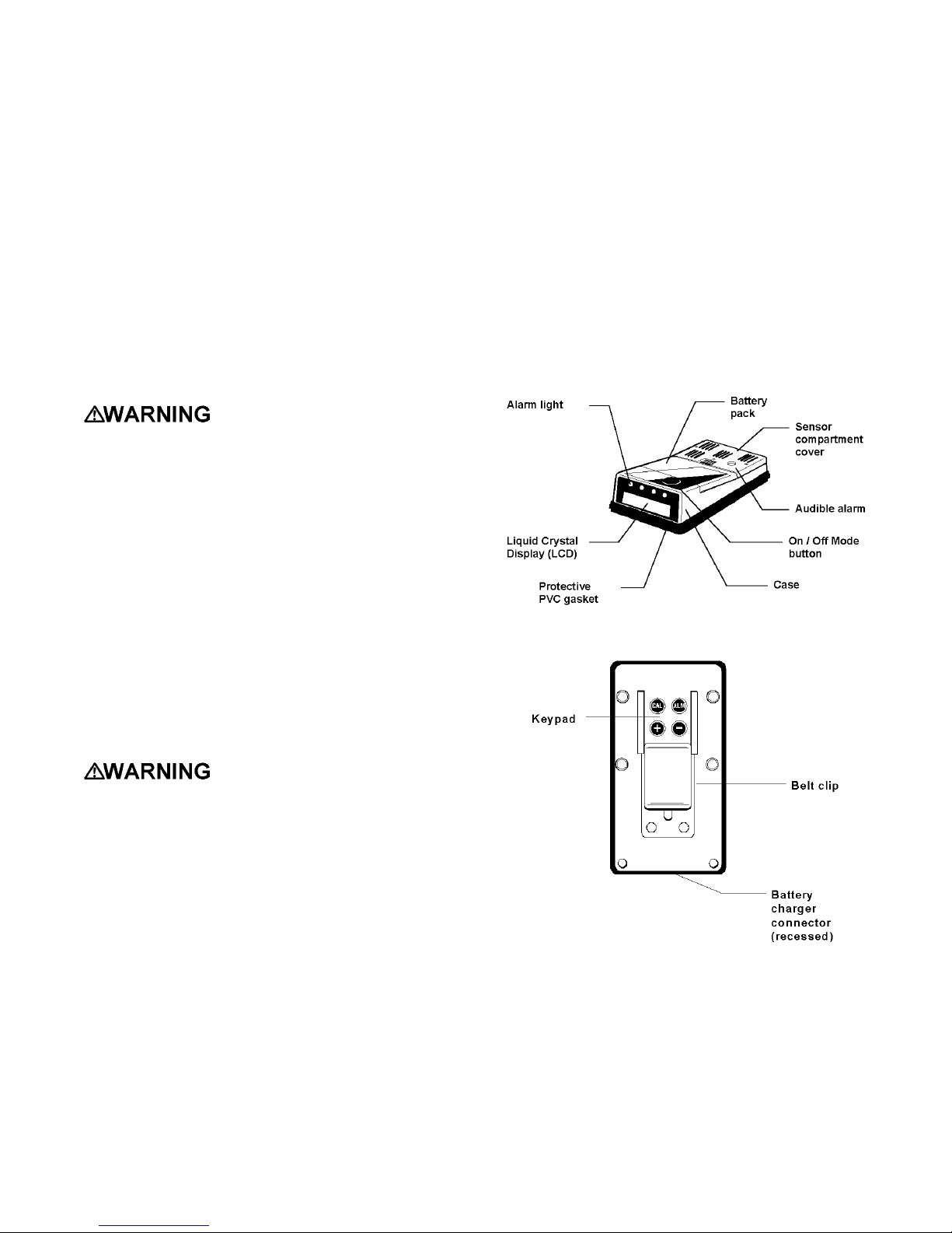
Figure 1.10.1. Major PhD Ultra Features (Top and
Front Surfaces)
Figure 1.10.2. Major PhD Ultra Features (Bottom)
(1) Case: The instrument is enclosed in a solid,
stainless steel-impregnated polycarbonate case.
A water-resistant PVC gasket between the upper
and lower sections of the case protects against
leakage or exposure to liquids.
(2) Front face: The front face of the instrument
houses the meter display and alarm lights.
13
Page 14

(3) LCD display: A "Supertwist" liquid crystal
display (LCD) meter allows display of readings,
messages, and other information.
(4) Alarm lights: Four LED (light emitting diode)
alarm lights provide a visual indication of alarm
state. Each light is dedicated to a single
channel of detection, and will emit a bright red
light when a sensor alarm level is exceeded.
One of the alarm light assemblies also includes
a photo-sensor used to monitor the level of
background illumination. An automaticallyactivated backlight brightens the meter display
whenever the instrument is taken into a dark
area.
(5) On / Off "mode" button: The large black push-
button is called the "mode" button. It is used to
turn the PhD Ultra on and off and to control
most other operations, including the automatic
calibration adjustment.
(6) Sensor compartment cover: The sensors are
protected by a vented sensor compartment
cover. Its own protective filter cap indiv idually
protects each sensor. A water-resistant PVC
gasket and inner-liner protect the instrument
against leakage or exposure to liquids.
(7) Audible alarm orifice: A cylindrical orifice
extending through the sensor compartment
cover houses the audible alarm. The waterproof
audible alarm seats directly to the PVC innerliner to protect the instrument against leakage or
exposure to liquids.
(8) Battery pack: Two types of interchangeable
battery packs (rechargeable NiCad and
disposable alkaline) are available for use in the
PhD Ultra. NiCad battery packs may be
recharged while the pack is installed in the
instrument, or the battery pack may be removed
from the instrument and recharged separately.
Chapter 2 of the PhD Ultra owner's manual
covers battery replacement and charging
procedures.
(9) Battery charger connector: A water-resistant
connector at the rear of the case is used to
connect the PhD Ultra to the “drop in” style PhD
Ultra fast charger.
(10) Bottom surface: A sturdy clip allows the
user to wear the PhD Ultra on a belt or other
article of clothing. Snaps are prov ided to hold
the PhD Ultra securely in the padded leather
weather cover.
(11) Key pad: The key pad is located on the
back of the PhD Ultra under the belt clip. Slide
the belt clip towards the rear of the instrument to
access the four small push-buttons. The key
pad consists of, four buttons labeled “+”, “-”,
“CAL”, and "ALM”. These buttons are normally
only used during set-up and other programming
procedures.
Use of these push buttons is reserved for
authorized personnel.
1.11 PhD Ultra accessories
Each PhD Ultra is delivered in a foam lined box
containing the PhD Ultra detector, padded leather
weather cover, carrying strap, sample draw /
calibration adopter, hand-aspirated sample-draw kit
(with 10 feet of sample draw tubing), 2 feet of
additional tubing for use during calibration,
reference manual, quick reference card, and
comprehensive training video.
The sample draw kit comprises a slip-on sample
draw / calibration adapter, squeeze bulb, sample
probe, replacement sample probe filters, and ten
feet of tubing.
1.11.1 “Alkaline” PhD Ultra detectors
If the PhD Ultra has been purchased as an “alkaline”
instrument the standard accessories also include an
alkaline battery pack and a set of 3 disposable AA
alkaline batteries.
1.11.2 “NiCad” PhD Ultra detectors
If the PhD Ultra has been purchased as a “NiCad”
instrument the standard accessories additionally
include a NiCad battery pack, slip in PhD Ultra fast
charger, as well as a spare alkaline battery pack and
set of disposable batteries.
1.11 PhD Ultra kits
PhD Ultra detectors may also be purchased as part
of complete kits.
1.11.1 PhD Ultra Confined Space Kits
Besides the standard accessories included with
every PhD Ultra, Confined Space Kits also include
calibration fittings, regulator, one cylinder of each of
the appropriate calibration gases and foam lined
waterproof carrying case for the instrument,
calibration materials and other accessories.
Cylinders used in Confined Space Kits contain
either 58 or 103 liters depending on the specific
mixture of gas.
1.11.2 PhD Ultra Value Packs
It is also possible to order the PhD Ultra configured
as a “Value Pack”. The Value Pack comprises an
alkaline PhD Ultra, all standard accessories, 34 liter
cylinder of all-in-one calibration gas, fixed flow rate
regulator, and foam lined carrying case.
14
Page 15
Chapter 2 Basic operation
Note: If the date and time are incorrect, see
section 4.5.3.3 for instructions.
2.1 Operation overview
2.1.1 Turning the PhD Ultra on
The large black push-button on the top of the PhD
Ultra case is called the "MODE" button. It is used to
turn the PhD Ultra on and off, and to control most
other operations of the instrument. Push the mode
button once to turn the PhD Ultra on.
2.1.2 Start-up sequence
After the detector has been turned on, it will
automatically go through an electronic self test and
start up sequence that will take approximately thirty
seconds. During the self-test sequence, the display
backlight will momentarily turn on, the visual LED
alarm lights will flash, and the audible alarm will
sound. The PhD Ultra will also determine which
“Smart Sensors” are currently installed, and whether
there have been any changes since the last time the
instrument was used.
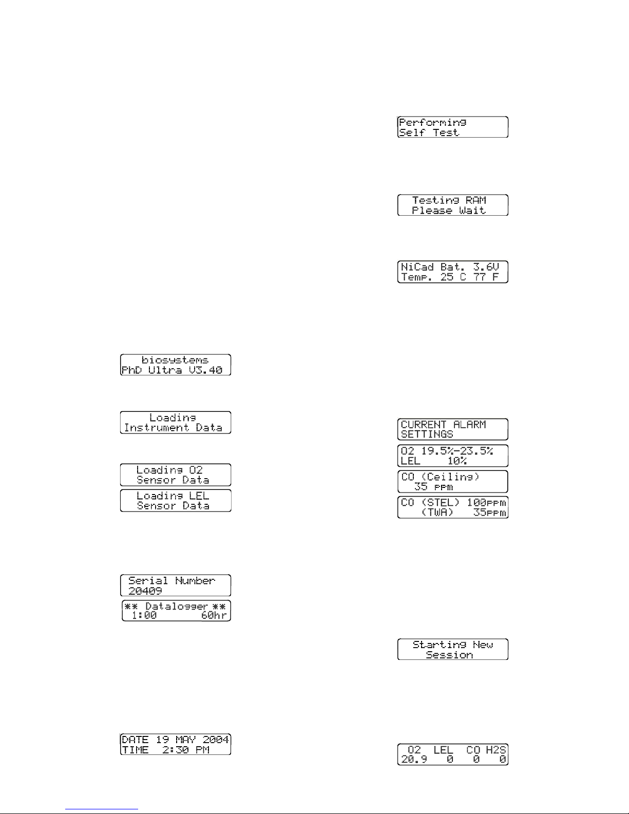
The first screen shown during the start-up sequence
gives the instrument’s software version number.
The instrument will proceed to load instrument and
sensor data.
The PhD Ultra automatically evaluates itself to
determine its electronic fitness for use by
performing an electronic self-test.
During the self-test the audible alarm will sound and
each LED alarm light will be briefly activated. The
system’s onboard memory (RAM) will then be
tested.
The next screen shows the type of battery pack
installed, the current battery pack voltage, and
temperature in both Centigrade and Fahrenheit.
The temperature displayed is not necessarily the
temperature of the ambient air that surrounds the
instrument. The temperature shown is actually a
reading taken on the inside of the instrument case in
the area where the sensors are located. This
information is used by the PhD Ultra microprocessor
to properly adjust the sensor output when the
instrument is used in changing temperatures.
The current alarm settings will be shown before the
instrument is ready for use.
A screen will be shown for each sensor that is
recognized in the instrument.
etc.
The instrument serial number will be shown followed
by the datalogger interval screen.
The figure at the left represents the sampling
interval in minutes. The figure at the right
represents the operating time before the oldest data
will be overwritten by new data.
For more information on the datalogger
sampling interval settings, see section 4.5.3.
The instrument’s current date and time settings will
then be shown.
Note: PhD Ultra gas reading alarms are user
adjustable and may be set anywhere within the
range of the sensor channel. In many cases it is
possible to comply with OSHA guidelines while
using higher alarm points than the “default”
factory alarm settings. Factory default settings
may be easily restored at any time. The
procedure for changing or restoring the default
alarm settings is discussed in Chapter 4.
The final screen in the self-test and start-up
sequence is the current gas level screen. This
screen shows the kind of sensors currently installed
and the current readings. When the instrument is
operated in either the “Basic” or “Technician” mode,
numerical readings are shown.
15
Page 16
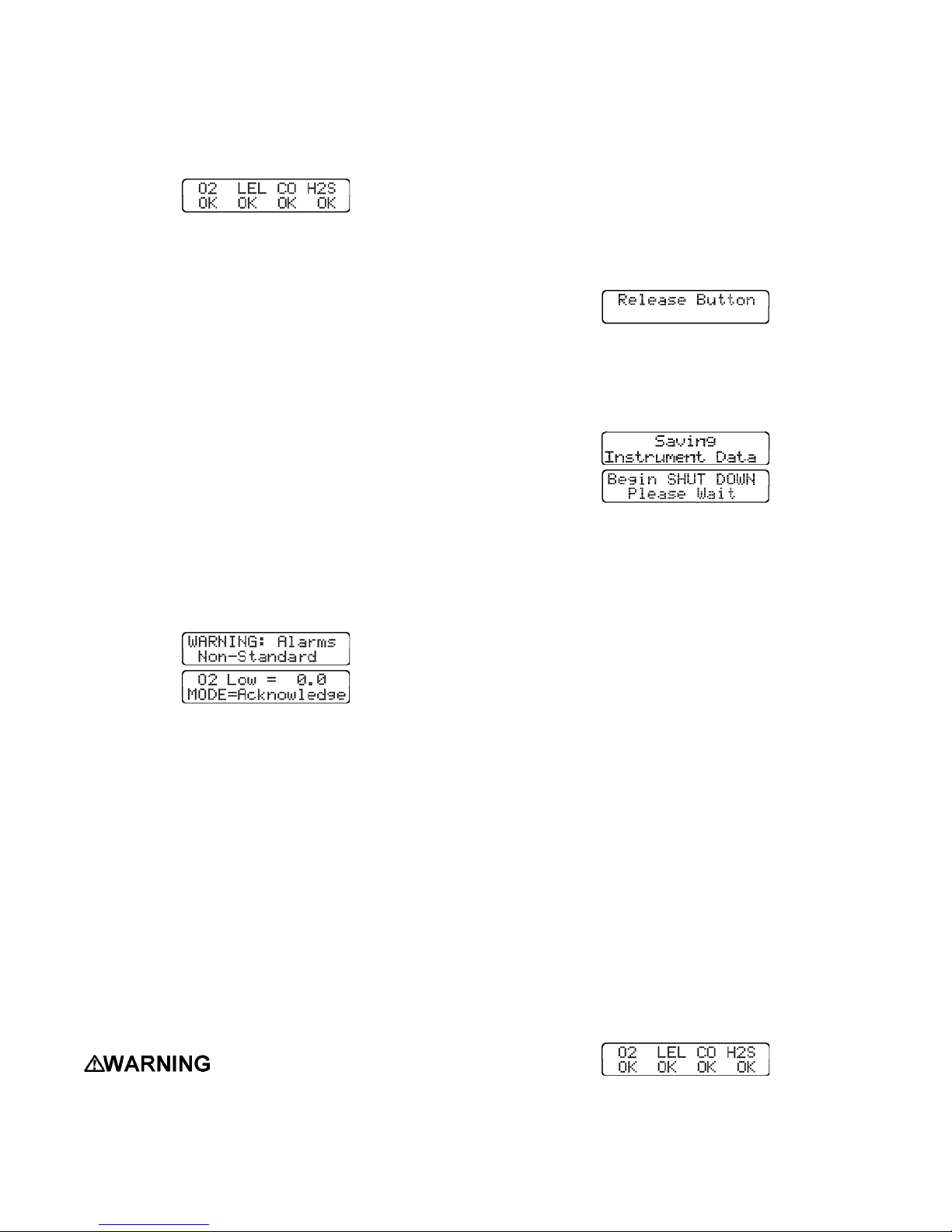
If the instrument is operated in the “Text Only” mode
an “OK” message will be displayed as long as an
alarm set point has not been exceeded. If the
readings exceed a pre-set alarm level, the message
changes from “OK” to a numerical reading, the LED
alarm light flashes, and the audible alarm sounds.
2.1.3 Other start-up screens
Several additional screens may be shown under
some circumstances. Usually the screen message
is self-explanatory.
2.1.3.1 “Self-adjusting” or “Correcting”
In some cases the PhD Ultra may detect an
electronic fault or need for adjustment when first
turned on. A screen will indicate the nature of the
fault. If the instrument is capable of correctly
adjusting itself a screen will indicate “Self Adjusting”
or “Correcting”. When the correction has been
successfully completed the instrument will continue
the self-test and start-up sequence.
2.1.3.2 “Non-standard alarms”
If the instrument determines that dangerously nonstandard or custom oxygen or LEL combustible gas
alarms have been selected, the LCD will display the
message “Non-Standard Alarms” at start-up. The
LCD will display the alarm settings for the affected
sensors.
The “Needs Cal” warning message may be
acknowledged (and silenced) by pressing the mode
button.
2.1.4 Turning the PhD Ultra off
Hold the mode button down for three seconds to
turn the instrument off. In order to prevent
accidental shut downs, the mode button must be
depressed for a full three seconds in order to turn
the instrument off. After three seconds (marked by
three beeps of the audible alarm) the LCD display
will display the message "Release button”.
If the button is released prior to the display of the
"Release button" message, the instrument will not
turn off.
After the button is released the LCD display will
save intrument data and then shut down
The shutdown sequence is complete when the
meter display blanks out in about ten seconds.
2.2 Operating modes
The PhD Ultra offers a choice of three modes of
operation, "Text Only”, "Basic”, and "Technician”.
Mode selection is a function of how much
information is required, the skill level of the user,
and the nature of the job.
Press the mode button to proceed with the nonstandard settings.
Note: Factory default settings may be easily
restored at any time. The procedure for
restoring factory default alarm settings is
discussed in Chapter 4.
2.1.3.3 “Needs Cal”
Biosystems EEPROM equipped “smart” sensors
automatically identify themselves to the PhD Ultra in
which they are installed. The PhD Ultra is aware
any time sensors are added, deleted, changed or
replaced. Any time a change is made to the
sensors, the PhD Ultra will display the message
“Needs Cal” followed by a list of the affected
sensors. This is an indication that the accuracy of
the affected sensors should be verified by exposure
to known concentration test gas before further use.
Following a “Needs Cal”
warning, the PhD Ultra should not be put back
into service or used until the accuracy of any
affected sensor has been verified by exposure to
the appropriate known concentration test gas.
Regardless of operating mode selection, anytime
the PhD Ultra is on it is remembering the peak
readings of all gases measured, and is calculating
both Time Weighted Averages and Short Term
Exposure Levels for any toxic gas sensors installed.
Regardless of operating mode, the PhD Ultra will go
into alarm whenever an alarm set point is exceeded.
An alarm condition occurs when one of the sensor
readings exceeds a pre-set alarm level. When an
alarm condition occurs, the current gas readings
screen will change to reflect the new gas value, the
LED alarm lights will flash, and the audible alarm
will sound.
2.2.1 Text Only mode
The simplest mode of operation is the "Text Only"
mode. In this mode, during normal operation, the
LCD screen does not display numerical readings,
only the indication "OK”.
An alarm condition occurs when one of the sensor
readings exceeds a pre-set alarm level. The
indication will change from "OK" to the numerical
gas value that is registered by the instrument. The
16
Page 17
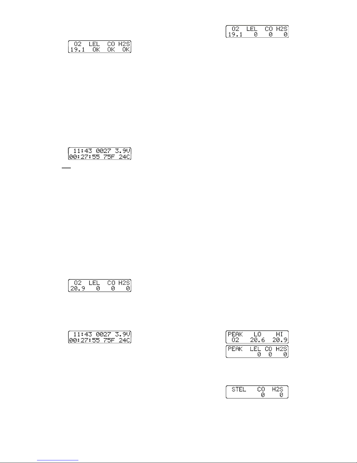
LED alarm lights will flash and the audible alarm will
sound during an alarm condition.
PhD Ultra alarms are normally self-resetting. When
readings drop back below the pre-set alarm levels,
the screen returns to the "OK" indication, and visual
and audible alarms cease.
In Text Only mode, press the mode button to toggle
between the two available screens. The first screen
is the current gas readings screen, which in Text
Only mode will show OK unless an alarm set point
has been exceeded. Press the mode button to
access the runtime screen, which shows the time,
battery voltage, running time for the instrument
since last turned on (in hours and minutes), and
temperature (in both Fahrenheit and Centigrade).
Note: It is not possible to make calibration
adjustments while the PhD Ultra is operated in
the Text Only mode. The PhD Ultra must be
operated in either Basic or Technician mode in
order to initiate the “Auto-Calibration”
sequence.
2.2.2 Basic mode
The "Basic" mode of operation provides the user
with numerical readings at all times, but keeps
operation of the gas detector simple.
In Basic mode the user has access to two "screens"
of information. Press the mode button to toggle
between the two available screens. The first screen
is the current gas readings screen, which will always
provide numerical readings in Basic mode.
PhD Ultra alarms are normally self-resetting. When
readings drop below the pre-set alarm levels, visual
and audible alarms cease, and the instrument
resumes normal operation.
2.2.3 Technician mode
The "Technician Mode" provides access to all
advanced functions and displays, including the
automatic calibration subroutines.
Calibration procedures are discussed in detail in
Chapter 3.
In Technician mode, following completion of the
start-up and self-test sequence, the current gas
readings screen will be shown with numeric displays
for all sensors. An alarm condition occurs when one
of the sensor readings exceeds a pre-set alarm
level. In an alarm condition, the numerical readings
change to reflect the new value, the LED alarm light
flashes, and the audible alarm sounds.
PhD Ultra alarms are normally self-resetting. When
readings drop back below the pre-set alarm levels,
visual and audible alarms cease, and normal
operation of the instrument resumes.
Press the mode button to scroll through the
numerous screens of information available in
Technician mode.
2.2.3.1 Peak readings
From the current gas readings screen in Technician
mode, press the mode button once to display the
“Peak” readings for the gases being measured.
These readings represent the highest (or in the case
of oxygen highest and lowest) values registered by
the instrument during any period of operation. Peak
readings are updated on a second by second basis.
Press the mode button to access the runtime
screen, which shows battery voltage, running time
for the instrument since last turned on (in hours and
minutes), and temperature (in both Fahrenheit and
Centigrade).
In Basic mode it is possible to enter the “AutoCalibration” mode in order to make zero and span
calibration adjustments. This feature is not enabled
when the instrument is operated in the Text Only
mode.
Calibration procedures are discussed in detail in
Chapter 3.
An alarm condition occurs when one of the sensor
readings exceeds a pre-set alarm level. The
numerical reading changes to reflect the new value,
the LED alarm light flashes, and the audible alarm
sounds.
The PhD Ultra will automatically cycle between two
peak reading screens, one for oxygen, and one for
the other gases being measured. The oxygen peak
reading screen shows both the high (HI) and low
(LO) readings.
2.2.3.2 STEL readings
Press the mode button again to display the “STEL”
readings for the toxic sensors currently installed.
The STEL (Short Term Exposure Limit) for a
particular toxic gas is the maximum average
concentration to which an unprotected worker may
be exposed in any 15 minute interval during the day.
The STEL value displayed by the PhD Ultra is the
17
Page 18
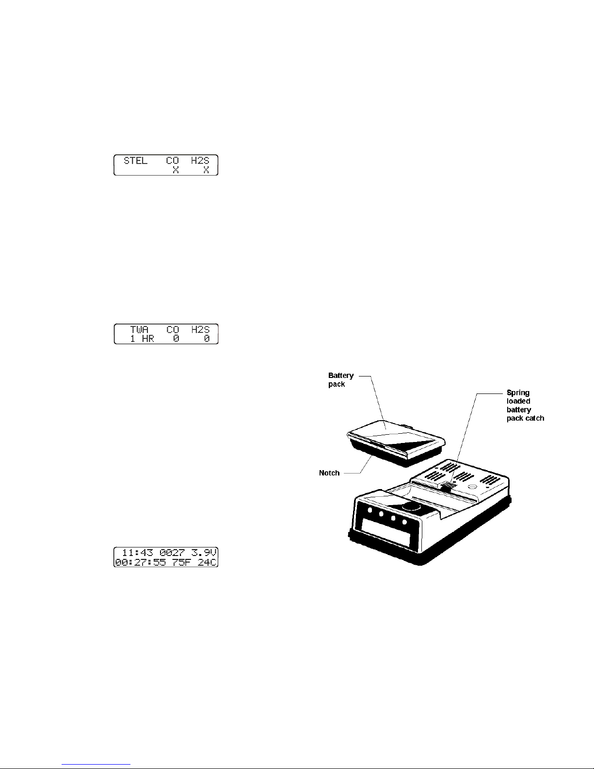
average concentration for the most recently
completed 15 minutes of operation.
Note: For the first 15 minutes after the PhD
Ultra is initially turned on the STEL reading is a
projected value. The PhD Ultra will begin
projecting a STEL value after the first 30
seconds of operation. For the first 30 seconds
the STEL screen will show an "X" where the
reading should be.
The STEL reading is constantly updated. Audible
and visual gas alarms will be activated whenever
the most recent 15-minute average exceeds the
STEL alarm set point.
Appendix A discusses Permissible Exposure
Limit alarm calculations in greater detail.
2.2.3.3 TWA readings
Press the mode button again to display the TWA
(Time Weighted Average) exposure levels. TWA
values are calculated by projecting exposures over
an eight-hour period.
It is not possible to compute a toxic gas TWA until
the PhD Ultra has been monitoring for at least 15
minutes. Until the minimum monitoring time has
elapsed, the TW A screen will show an "X" where the
reading should be.
Note: After 30 minutes the screen will also
begin to indicate how long the instrument has
been on. This “run time” indication will be
given in hours and completed 15-minute
intervals.
Note: Shifting modes or otherwise
reprogramming the instrument should only be
done by employees who are authorized to do so.
2.3 Batteries
PhD Ultra batteries are housed in removable battery
packs. Two types of battery packs (rechargeable
NiCad and alkaline) are available for use. Battery
packs are fully interchangeable and can be replaced
while the instrument is in the field. It is not
necessary to open the instrument case to replace or
change the battery pack.
Battery packs are clearly labeled as containing
either NiCad or disposable alkaline batteries. The
gasketed battery packs are held firmly in place by a
spring-loaded catch on the instrument. The PhD
Ultra should be turned off before changing or
replacing battery packs.
Note: The PhD Ultra is designed to turn itself on
whenever a battery pack is removed and then
replaced. This is to ensure that in the event of a
power interruption the instrument is not
accidentally turned off. Any time the battery
pack is momentarily removed or replaced with
another it will be necessary to manually turn the
PhD Ultra off if the instrument is not going to be
put to immediate use.
2.2.3.4 Runtime screen
Press the mode button again to display the runtime
screen, which shows battery voltage, running time
for the instrument since last turned on (in hours and
minutes), and temperature (in both Fahrenheit and
Centigrade).
Press the mode button again to return to the current
gas readings screen.
2.2.4 Changing operating modes
To change operating modes, simply slide the belt
clip located on the back of the PhD Ultra case
downward to expose the four push buttons on the
instrument keypad. Push the "+" and "-" buttons at
the same time to change operating modes. Each
time the operating mode is changed the display
screen will briefly indicate the operating mode that
has been selected. The instrument will not incur
any loss of data due to a change in operating mode.
Figure 2.3. PhD Ultra with Battery Pack Removed
To remove the battery pack pull back on the springloaded catch, and pull the battery pack upward and
backwards (towards the rear of the instrument). To
replace the battery pack, seat the notch at the front
of the battery pack housing to the matching lip in the
PhD Ultra instrument case. When the battery pack
is properly positioned, press down gently on the rear
of the battery pack to engage the spring loaded
catch.
18
Page 19
2.3.1 NiCad battery pack
When the PhD Ultra is operated in the diffusion
mode, the rechargeable NiCad battery pack will
provide up to 12 hours of continuous use. The
NiCad pack is a sealed assembly that may not be
disassembled in the field. The NiCad battery may
be recharged while the pack is installed in the
instrument, or the battery pack may be removed
from the instrument and recharged separately in the
PhD Ultra Fast Charger.
Fully assembled NiCad battery packs may be
removed or replaced while the instrument is being
used in a hazardous location.
The PhD Ultra must be located
in a non-hazardous location during the charging
cycle. Charging the PhD Ultra in a hazardous
location may impair intrinsic safety.
The PhD Ultra is Classified by Underwriters
Laboratories, Inc. and the Canadian Standards
Association as to Intrinsic Safety for use in Class
I, Division 1, Groups A, B, C, & D Hazardous
Locations. This classification is void while the
PhD Ultra is operated while connected to the
battery charger in hazardous areas.
voltage is too low to allow the safe operation of the
instrument.
Battery pack voltage may be checked at any time
while the instrument is in normal operation by
pressing the mode button to access the runtime
screen. Allow the PhD Ultra to operate two to three
minutes before checking battery voltage. A reading
of 3.8 Volts or higher indicates that either type of
battery pack has sufficient power to provide eight
hours of continuous operation.
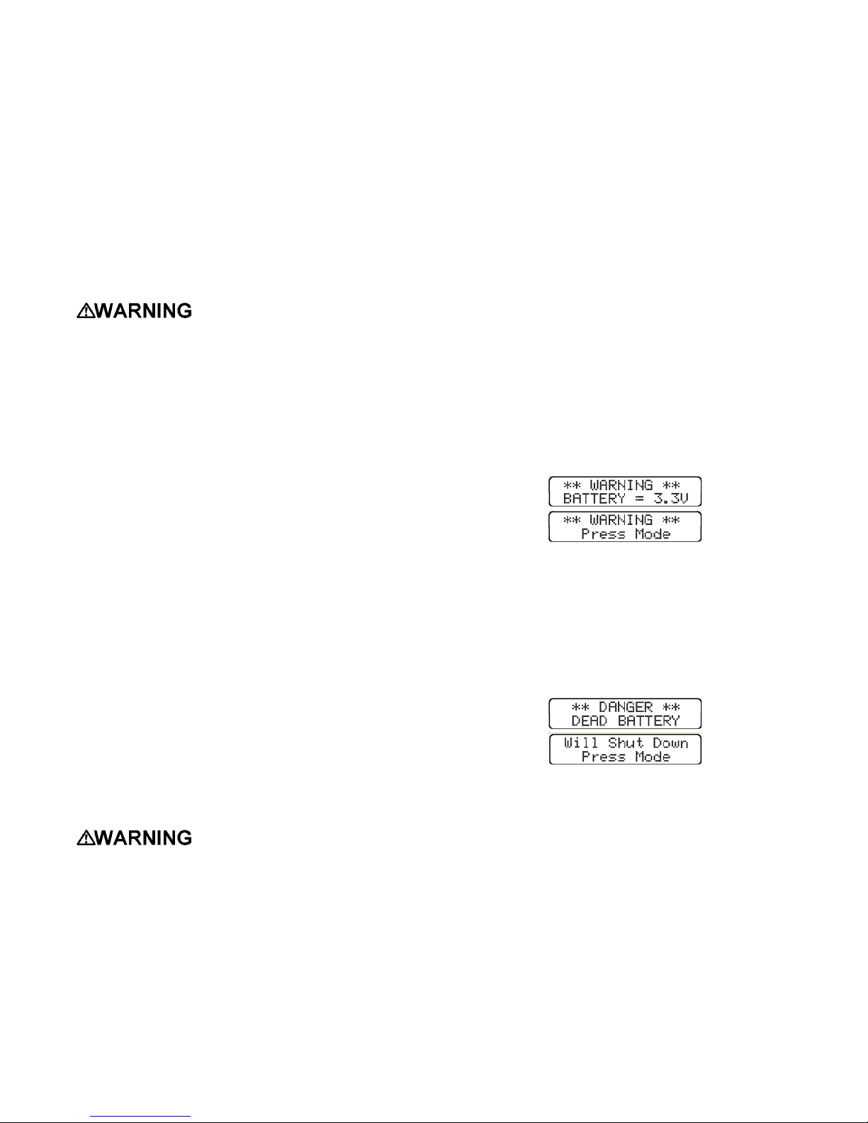
2.3.3.1 Low battery alarm settings for NiCad
battery packs
When NiCad battery pack voltage is reduced to 3.3
Volts, an audible alarm will sound, and the display
screen will indicate that a low battery condition
exists. At this stage, the low battery alarms may be
silenced for a fifteen-minute period by pressing the
mode button. The alarm will continue to sound
every fifteen minutes until the voltage reaches 3.25
Volts.
The initial low battery screen alternates with a
second screen that indicates that the alarm may be
silenced by pressing the mode button.
2.3.2 Disposable alkaline battery pack
The PhD Ultra may also be equipped with a battery
pack designed to hold a set of 3 AA disposable
alkaline batteries. When the PhD Ultra is operated
in diffusion mode, the alkaline battery pack will
provide up to 12 hours of continuous use. The
alkaline pack must be removed from the instrument
in order to replace the batteries. The alkaline
battery pack is removed in the same manner as the
NiCad pack. To maintain intrinsic safety the
alkaline battery pack cover is held in place by a
captive screw that is located in the center of the
underside of the battery pack. To open the alkaline
pack, use a screwdriver to loosen the screw and
gently remove the cover.
Make sure that replacement batteries are properly
aligned in the battery pack housing before returning
the instrument to service.
The alkaline battery pack must
be located in a non-hazardous location
whenever the alkaline batteries are removed
from it. Removing the alkaline batteries from
the alkaline battery pack in a hazardous location
may impair intrinsic safety.
2.3.3 Low battery alarms
The PhD Ultra is designed to automatically
determine which type of battery pack has been
installed, and use the appropriate low battery
alarms. Alarms will be activated whenever battery
When battery pack voltage has dropped to 3.25
Volts it is no longer safe to continue to use the
instrument until the battery has been recharged. At
this point the alarm will begin to sound continuously,
and may no longer be silenced by pushing the mode
button. If voltage drops below 3.25 Volts the PhD
Ultra will display a "Dead Battery" message to warn
the user of imminent shut down. The instrument will
then automatically turn itself off.
The PhD Ultra NiCad battery pack should be
recharged as soon as possible after any low battery
alarm. It is important to recharge or replace the
battery pack before further use.
2.3.3.2 Low battery alarm settings for alkaline
battery packs
If the PhD Ultra has been equipped with a
disposable alkaline battery pack, the initial low
battery alarm will be activated when voltage is
reduced to 3.2 Volts. Protective shutdown occurs at
3.1 Volts.
2.3.4 Recharging NiCad battery packs
Standard accessories included with every “NiCad”
instrument include a slip-in PhD Ultra “Fast
Charger”. Each standard Fast Charger assembly
19
Page 20
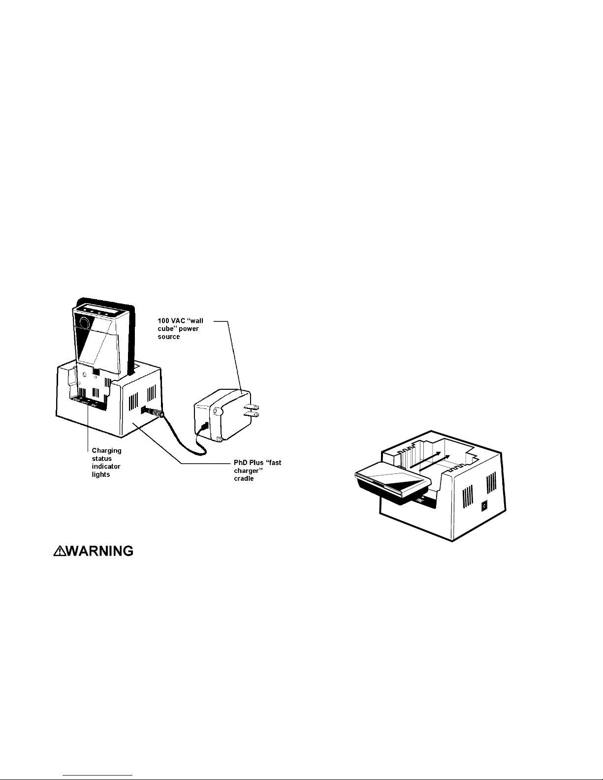
consists of two components a slip-in cradle and a
110 VAC “wall cube” type power source. European
and Australian chargers may use a different wall
cube.
NiCad battery packs may be recharged while they
are installed in the PhD Ultra detector, or they may
be removed from the instrument for separate
recharging. The Fast Charger is designed to
completely recharge NiCad battery packs in 2 hours.
When “fast” charging is complete the charger
automatically converts to a “trickle” charge to avoid
damage to the battery pack due to overcharging.
CAUTION: PhD Ultra NiCad battery packs may
only be charged with Biosystems battery
chargers. Use of any other charger may result
in damage to the instrument and voids the
standard Biosystems warranty.
NiCad battery pack equipped PhD Ultra detectors
should be kept continuously on the charger at all
times when not in use.
(4) Slip the PhD Ultra into the charger cradle and
check to see that the “FAST” (fast charger)
indicator LED on the charger cradle is lit.
Note: The “FAST” indicator will initially
light up and remain lit for the first 15
minutes of charging regardless of battery
pack voltage.
(5) When charging is complete the “FAST” indicator
will turn off. Charging is complete any time
after the “TRIC” (trickle charge) indicator is lit.
2.3.4.2 Charging the NiCad battery pack
separately from the instrument
(1) Check that the instrument is turned off. (If it is
not, press the mode button until the message
"Release button" appears on the screen.
(2) Connect the charger cradle to the 110 VAC “wall
cube” power source.
(3) Plug the “wall cube” in and check to see that the
“PWR” (power-on) indicator LED on the charger
cradle is lit.
(4) Remove the NiCad battery pack from the PhD
Ultra
Figure 2.3.4. PhD Ultra Fast Charger (standard
version)
2.3.4.1 Charging procedure with NiCad battery
pack installed
The PhD Ultra must be located
in a non-hazardous location during the charging
cycle. Charging the PhD Ultra in a hazardous
location may impair intrinsic safety.
(1) Check that the instrument is turned off. (If it is
not, press the mode button until the message
"Release button" appears on the screen.)
(2) Connect the charger cradle to the 110 VAC “wall
cube” power source.
(3) Plug the “wall cube” in and check to see that the
“PWR” (power-on) indicator LED on the charger
cradle is lit.
(5) Slip the NiCad battery pack into the charger as
shown in Figure 2.3.4.2. Check to see that the
“FAST” (fast charge) indicator LED is lit.
(6) Charging is complete any time after the “TRIC”
(trickle charge) indicator is lit.
Figure 2.3.4.2. Placement of NiCad Battery Pack in
Fast Charger
2.3.4.3 “Cycling” NiCad battery packs
If the NiCad battery duration is not being received,
try exercising or "cycling" the battery. To cycle the
NiCad battery pack:
(1) Install the battery pack in the PhD Ultra and turn
the instrument on.
(2) Allow the instrument to run until the low battery
voltage alarms have been activated.
(3) Recharge the NiCad battery pack.
20
Page 21
(4) Repeat procedure as necessary.
Over a period of three or four days of cycling it is
frequently possible to restore a significant portion of
lost performance. If cycling fails to improve
performance, the battery pack will probably need to
be replaced.
2.4 Methods of sampling
The PhD Ultra may be used as either a "Diffusion"
or "Sample-Draw"-type monitoring device.
In normal operation, the PhD Ultra detector is worn
on the belt, used with its shoulder strap, or held in
the hand. Once turned on, the PhD Ultra monitors
continuously. The atmosphere being measured
reaches the sensors by diffusing through vents in
the sensor compartment cover. Normal air
movements are enough to carry the sample to the
sensors. The sensors react quickly to changes in
the concentrations of the gases being measured.
This type of "diffusion" operation monitors only the
atmosphere that immediately surrounds the
detector.
It is possible to use the PhD Ultra to sample remote
locations by using a sample-draw kit. Two sampledraw kits are available. In each case the gas
sample is drawn in through a probe assembly, and
travels through a length of hose back to the
instrument. One type of kit uses a hand-operated
squeeze-bulb to draw the sample through the hose
while the other uses a motorized continuous
mechanical pump that draws its power directly from
the PhD Ultra battery pack. A hand-aspirated
sample-draw kit is included as an accessory with
every PhD Ultra.
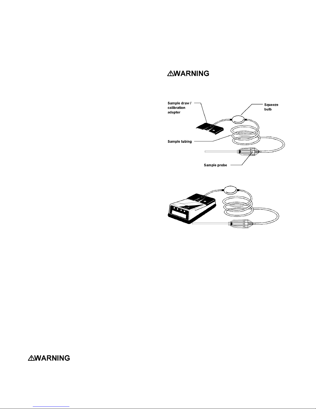
2.4.1 Using the hand aspirated sample
draw kit
(1) Connect the slip-on sample draw / calibration
adapter with the squeeze bulb and hose
assembly.
(2) Connect the end of the hose closest to the bulb
to the sample draw adapter.
(3) Connect the other end of the hose to the sample
probe as shown in Figure 2.4.1.1.
(4) Attach the sample draw adapter to the PhD
Ultra as shown in Figure 2.4.1.2.
(5) Cover the end of the sample draw probe
assembly with a finger, and squeeze the
aspirator bulb. If there are no leaks in the
sample draw kit components, the bulb should
stay deflated for a few seconds.
Failure to test the sample
draw kit prior to each use may result in
inaccurate readings.
(6) Insert the end of the sample probe into the
location to be sampled.
(7) Squeeze the aspirator bulb one time for each
foot of sample hose for the sample to reach the
sensor compartment. Then continue squeezing
the bulb for an additional 45 seconds until
readings stabilize.
Failure to correctly follow the
usage instructions for the sample draw kit may
lead to inaccurate readings.
(8) Note the gas measurement readings.
Figure 2.4.1.1. PhD Ultra hand aspirated sample draw
kit
Figure 2.4.1.2. PhD Ultra with hand aspirated sample
draw kit attached
CAUTION: Hand aspirated remote sampling
only provides continuous gas readings for the
area in which the probe is located when the bulb
is being continuously squeezed.
Each time a reading is desired, it is necessary to
squeeze the bulb a sufficient number of times to
bring a fresh sample to the sensor compartment and
to continue squeezing for another 45 seconds or
until readings stabilize. If continuous remote
sampling is required, a battery operated, continuous,
mechanical sample-draw pump should be used.
2.4.2 Continuous (slip-on) sample draw
pump
Use of the slip-on sample draw pump allows the
PhD Ultra to continuously monitor remote locations.
The pump is powered directly by the PhD Ultra
battery. A flashing “P” indicator in the upper left
corner of the LCD display indicates that the pump is
attached and in normal operation.
21
Page 22
CAUTION: Never perform remote sampling
with the PhD Ultra without the sample probe
assembly. The sample probe handle contains
replaceable filters designed to block moisture
and remove particulate contaminants. If the
pump is operated without the probe assembly in
place, contaminants may cause damage to the
pump, sensors and internal components of the
PhD Ultra.
The sample draw pump includes a unique pressure
sensor designed to protect the PhD Ultra from
exposure to water or other liquids. If there is a
change in pressure in the sample draw assembly
due to fluid intake, the pump immediately shuts
down. After a few seconds audible and visual
alarms indicating a low flow condition will also be
activated.
CAUTION: Insertion of the sample draw tube
into a fluid horizontally or at a low angle may
lead to water ingress and may cause damage to
the PhD Ultra.
The pressure sensor in the sample draw pump is
designed to detect changes while the sample-draw
probe is being held in a vertical position. If the
probe is held horizontally or at a low angle when
inserted into a fluid, a pressure drop sufficient to
cause the pump to shut down may not be generated,
and water could be drawn into the pump assembly.
In order to avoid potential damage, care must be
taken to keep the probe vertical any time fluids
might be present.
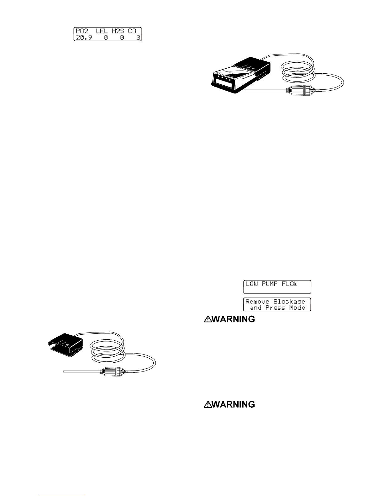
Figure 2.4.2.1.2. PhD Ultra with sample drawing
pump attached
(3) Slip the pump onto the PhD Ultra as shown
above in Figure 2.4.2.1.2.
(4) Make sure the pump is securely attached. (You
should hear a solid “click” as the pump housing
catch engages with the edge of the sensor grill
cover.)
(5) The pump will turn on automatically when
properly attached to the PhD Ultra.
(6) Cover the end of the sample draw probe
assembly with a finger. If there are no leaks in
the sample draw kit components, the pump
should go into a low-flow alarm and shut down,
and the audible and v isual low flow alarms
should be activated. A message screen will
identify that there is a low pump flow condition.
A second screen will advise you to remove the
blockage and press “mode” to resume
operation.
2.4.2.1 Using the continuous sample draw pump
(1) Turn the PhD Ultra on.
Figure 2.4.2.1.1. Sample draw pump and probe
assembly
(2) Connect the slip-on battery operated pump with
the hose and probe assembly as shown above
in Figure 2.4.2.1.1.
Failure to test the pump and
sample draw kit prior to each use may result in
inaccurate readings.
(7) Insert the end of the sample probe into the
location to be sampled.
(8) Wait long enough for the pump to have drawn
the sample through the entire length of hose,
and for the sensors to have stabilized. (Allow
one additional second for each foot or three
seconds for each meter of sample hose.)
Failure to correctly follow the
usage instructions for the pump sample draw kit
may lead to inaccurate readings.
(9) Note gas measurement readings
22
Page 23
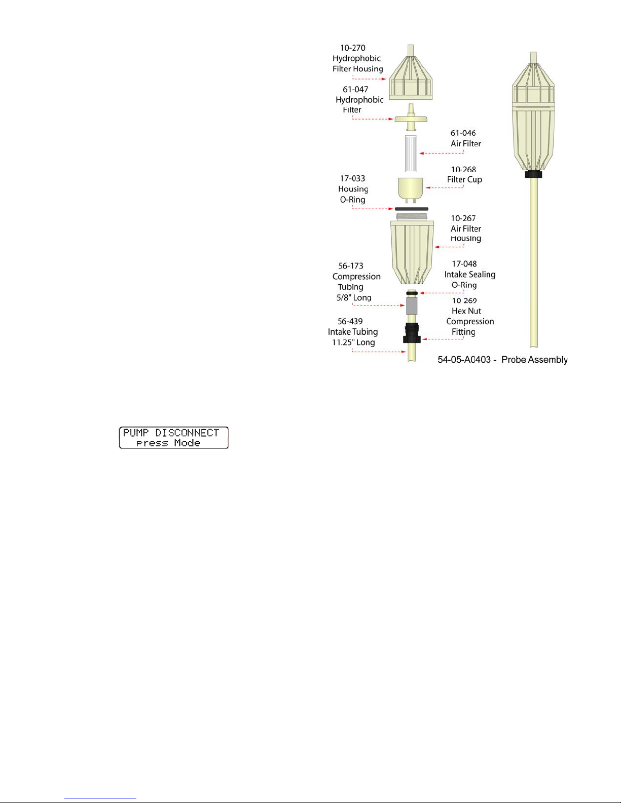
2.4.2.2 Protective “low flow” shut-downs
If a protective pump shut-down occurs, the following
steps should be taken before the instrument is put
back into use:
(1) Turn off the PhD Ultra detector and disconnect
the sample draw pump.
(2) Remove the sample draw assembly from the
area being monitored. Be careful to keep the
sample draw probe in a vertical position.
(3) Examine the sample draw probe and hose to
make sure no fluids remain trapped.
(4) Allow any trapped fluids to completely drain. (It
may be necessary to disconnect the hose or
sample draw probe before drainage can occur.)
(5) Replace the sample draw probe filters if
necessary.
(6) Re-attach the pump in fresh air and wait for
readings to stabilize.
(7) Resume sampling.
2.4.2.3 Resuming diffusion monitoring
In order to stop using the pump and resume
diffusion monitoring, simply disconnect the pump
assembly from the PhD Ultra. The audible and
visual alarms will be activated and the LCD will
display the message “Pump Disconnect”. Press the
mode button to acknowledge and resume normal
diffusion operation.
2.4.3 Sample probe assembly
The sample probe handle contains moisture barrier
and particulate filters designed to remove
contaminants that may cause harm to either the
continuous pump or the instrument. Never operate
the sample draw pump unless the hose and
probe assembly is attached!
Particulate contaminants are removed by means of
a cellulose filter similar to those used in filter
cigarettes. The hydrophobic filter includes a 0.1 Pm
Teflon¥ barrier which blocks the flow of moisture as
well as any remaining particulate contaminants.
Figure 2.4.3. PhD Ultra sample probe assembly
Sample probe filters should be replaced whenever
visibly discolored due to contamination, or when the
continuous pump “low flow” alarm indicates
blockage. A spare filter replacement kit (part
number 54-05-K0401) is included with every PhD
Ultra.
2.4.3.1 Changing sample probe filters
The threaded sample probe handle is unscrewed (as
shown in Figure 2.4.3.) to access the filters. The
particulate filter is held in place by means of a clear
filter bowl. To replace the particulate filter, remove
the old filter and bowl, insert a new filter into the
bowl, and slide the bowl back into place in the probe
handle. The hydrophobic barrier filter fits into a
socket in the rear section of the probe handle. (The
narrow end of the hydrophobic barrier filter is
inserted towards the rear of the handle.)
2.4.3.2 Changing sample probe tubes
The standard 11.5” long butyrate probe tube is held
in place by means of a hex-nut compression fitting
and compression sleeve. The standard probe tube
is designed to be easily interchangeable with other
custom length sections of 1/4” OD tubing, or probe
tubes made of other materials (such as stainless
steel).
Probe tubes are exchanged by loosening the hexnut compression fitting, removing the old tube,
sliding the compression sleeve into place around the
23
Page 24

new tube, inserting the new tube into the probe
handle, and finally replacing and re-tightening the
hex-nut.
Note: The sample probe must be checked for
leakage (as discussed in Section 2.4.1.)
whenever filters or probe tubes are exchanged
or replaced before it is returned to service.
2.5 Biosystems EEPROM equipped
“Smart Sensors”
Each sensor installed in a PhD Ultra detector is
equipped with its own non-volatile memory storage
device or “EEPROM”. The contents of the sensor’s
memory device are designed to be read and
updated directly by the PhD Ultra. The fact that
each sensor is capable of remembering and
communicating important information about itself to
the instrument allows for a number of important PhD
Ultra operating benefits.
2.5.1 Identification of type of sensor by
instrument
Any sensor installed in the PhD Ultra automatically
identifies itself to the instrument microprocessor.
The PhD Ultra automatically recognizes the sensors
installed, displays the sensor on the liquid crystal
display (LCD) and assigns the correct alarm
settings.
2.5.3 Sensor replacement
Sensor replacement procedures are covered in
detail in section 5.1.
2.5.4 Missing sensor
The PhD Ultra is able to determine if a sensor is
removed or becomes disconnected while the
instrument is in normal operation. Removal of a
sensor while the instrument is turned on will trigger a
“Missing Sensor” display message, and cause the
audible and visual alarms for the affected sensor
channel to be activated.
2.5.5 “Can’t ID sensor”
If the PhD Ultra is unable to read the EEPROM of a
smart sensor currently installed, or if a smart sensor
is removed while the instrument is turned off without
being replaced with another sensor, a “Can’t ID
Sensor” message will be displayed, and the affected
sensor channel, (for instance, “Toxic 1”) will be
identified.
Press the mode button to acknowledge the
condition, and allows the use of the instrument for
those sensors that can be successfully read by the
instrument.
2.5.2 Other information stored with the
sensor EEPROM
Besides being identified by type of sensor, recorded
sensor information also includes the sensor serial
number, the most recent calibration settings,
temperature compensation curves, and the most
recent alarm settings. The PhD Ultra automatically
updates all of this data for the sensors currently
installed whenever the instrument is turned on,
whenever a change is made during operation, and
whenever the instrument is turned off.
If a sensor is changed or replaced the PhD Ultra
notes that a change has occurred, displays a “Needs
Cal” message the next time the instrument is turned
back on, and identifies the affected sensors. Even if
the change is only to replace one sensor with
another of the same kind, the PhD Ultra will still
note the change in serial numbers of the sensors
installed, and display the “Needs Cal” message.
The accuracy of sensors
identified as “Needing Calibration” must be
verified by exposure to known concentration
calibration gas before the PhD Ultra is put back
into service. Failure to do so may result in
inaccurate and potentially dangerous readings.
24
Page 25

Chapter 3 Calibration
The PhD Ultra multi-gas detector has been designed
for easy calibration. A single control, the on/off
mode button, is used to initiate the automatic
calibration sequence and to automatically make
calibration adjustments.
It is also possible to manually calibrate the
instrument by using the four pushbuttons located on
the instrument keypad.
“One-Button Auto-Calibration” procedures are
discussed in Section 3.4. Manual calibration
procedures are discussed in Section 3.5.
3.1 Verification of accuracy
Accuracy of the PhD Ultra
should be checked periodically with known
concentration calibration gas. Failure to check
accuracy can lead to inaccurate and potentially
dangerous readings.
Always check the expiration
date on calibration gas cylinder(s) prior to use.
Expired calibration gas can lead to inaccurate
and potentially dangerous readings.
Verification of accuracy is a two step procedure. In
the first step the PhD Ultra is taken to an area where
the atmosphere is fresh and the readings are
checked. If the readings differ from those expected
in fresh air, a "zero" adjustment must be made.
Step two is to make sure the sensors are accurate
by exposing them to a test gas of known
concentration and noting the sensor response.
Oxygen readings are considered to be accurate
when the display is within ±0.5% of the expected
concentration as given on the calibration gas
cylinder. LEL and toxic readings are considered
accurate when they are between 90% and 120% of
the expected value as given on the calibration gas
cylinder. (CSA requires the reading to fall between
100% and 120% to be considered accurate). If
readings are accurate, there is no need to adjust
your gas detector. If the readings are inaccurate,
the instrument must be span calibrated before
further use.
Biosystems offers calibration kits and long lasting
cylinders of test gas specifically developed for easy
PhD Ultra calibration.
Use of non-standard
calibration gas and/or calibration kit
components when calibrating the PhD Ultra can
lead to inaccurate and potentially dangerous
readings, and may void the standard
Biosystems warranty.
Customers are strongly urged to use only
Biosystems calibration materials when
calibrating the PhD Ultra.
3.1.1 Effect of contaminants on PhD Ultra
sensors
The atmosphere in which the PhD Ultra monitor is
being used can have an effect on the sensors.
Sensors may be poisoned or suffer degraded
performance if exposed to certain substances.
There are three basic types of sensors that may be
installed in the PhD Ultra detector: oxygen,
combustible gas (LEL), and electrochemical toxic.
Each type of sensor uses a slightly different
detection principle so the conditions that affect the
accuracy of the sensors vary from one type of
sensor to the next.
The accuracy of the PhD Ultra
sensors should be checked immediately
following any known exposure to contaminants
by testing with known concentration test gas
before further use.
3.1.1.1 Effects of contaminants on oxygen
sensors
Oxygen sensors may be affected by prolonged
exposure to "acid" gases such as carbon dioxide.
The oxygen sensors used in Biosystems instruments
are not recommended for continuous use in
atmospheres which contain more than 25% CO
3.1.1.2 Effects of contaminants on combustible
sensors
Combustible sensors may be affected by exposure
to substances containing silicone (found in many
lubricants and hydraulic fluids), the tetra-ethyl-lead
in "leaded" gasoline, and halogenated hydrocarbons
(Freons, or solvents such as trichloroethylene and
methylene chloride). High concentrations of
hydrogen sulfide may also damage the sensor.
Note: See the Biosystems Standard Warranty in
Appendix G for a more extensive list of LEL
sensor contaminants.
Note: If the combustible sensor suffers a loss of
sensitivity, it tends to be lost first with regards
to methane.
A partially poisoned sensor might still respond
accurately to propane while showing a dangerously
reduced response to methane.
Biosystems’ “Propane Equivalent” calibration gas
mixtures have been developed to eliminate this
potentially dangerous source of calibration error.
Biosystems’ “Propane Equivalent” mixtures are
based on methane, so any loss of sensitivity to
methane is detected (and can be corrected)
immediately.
.
2
25
Page 26

Using Biosystems brand calibration gas and
regularly verifying accuracy ensures that proper
sensitivity is maintained for the life of the
sensor.
3.1.1.2.1 Effects of high concentrations of
combustible gas on the combustible sensor
The accuracy of combustible sensors may also be
affected by exposure to high concentrations of
combustible gas. To minimize the chance for
damage or loss of sensitivity to the combustible
sensor, the PhD Ultra is designed to "alarm latch"
whenever the concentration of combustible gas
exceeds 100 percent LEL. Under these conditions
the combustible gas reading will show an “X” to
indicate an over-limit condition. The current gas
reading display will alternate (toggle) with a screen
showing the message “LEL sensor over limit”. The
audible and visual alarms will sound continuously
until the instrument is manually reset by turning it
off, then turning the instrument back on in an area
where the air is known to be fresh.
A combustible sensor overrange alarm indicates a potentially explosive
atmosphere. Failure to leave the area
immediately may result in serious injury or
death!
In the event of a combustible
sensor over-range alarm, the PhD Ultra must be
turned off, brought to an area that is known to
be safe and then turned on again to reset the
alarm.
Make sure that the PhD Ultra
is located in fresh air before turning the
instrument back on after a combustible sensor
alarm latch condition has occurred. Fresh air
calibration adjustments may only be made when
the PhD Ultra is located in air that is known to
be fresh. After a combustible sensor alarm-latch
condition occurs, the accuracy of the
combustible gas sensor must be verified by
exposure to known percentage LEL test gas
before further use.
Note: The combustible sensor used in the PhD
Ultra requires a minimum of 10% oxygen by
volume in order to generate accurate
combustible gas readings. Combustible sensor
accuracy may be diminished if the instrument is
used in oxygen-deficient atmospheres.
A rapid up-scale reading
followed by a declining or erratic reading may
indicate a hazardous combustible gas
concentration that exceeds the PhD Ultra’s zero
to 100 percent LEL detection range. Failure to
leave the area immediately may result in serious
injury or death!
Avertissement: Toute lecture rapide et positive,
suivie d'une baisse subite au erratique de la
valeur, peut indiquer une concentration de gaz
hors gamme de détection qui peut être
dangereuse.
3.1.1.3 Effects of contaminants on toxic gas
sensors
Biosystems “substance-specific” electrochemical
“smart sensors” used to measure toxic gases have
been carefully designed to minimize the effects of
common interfering gases. “Substance-specific”
sensors are designed to respond only to the gases
that they are supposed to measure. The higher the
specificity of the sensor the less likely the sensor will
be affected by exposure to other gases which may
be incidentally present in the environment. For
instance, a “substance-specific” carbon monoxide
sensor is deliberately designed not to respond to
other gases that may be present at the same time,
such as hydrogen sulfide and methane.
Although great care has been taken to reduce crosssensitivity, some interfering gases may still have an
effect on toxic sensor readings. In some cases the
interfering effect may be positive and result in
readings that are higher than actual. In other cases
the interference may be negative and produce
readings that are lower than actual.
Cross sensitivity of PhD Ultra toxic sensors to
common interfering gases is listed in Appendix
E.
3.1.2 Biosystems “CO Plus” dual purpose
carbon monoxide / hydrogen sulfide
sensor
Carbon monoxide and hydrogen sulfide are the two
most common toxic gases associated with confined
space entry. In addition to “substance specific”
sensors designed to measure these toxic hazards,
Biosystems also offers a dual-purpose sensor
designed to detect both carbon monoxide and
hydrogen sulfide. The “CO Plus” sensor is ideal for
situations requiring use of a single sensor to monitor
simultaneously for both toxic hazards.
The “CO Plus” sensor is ideal for situations requiring
the use of a single sensor to monitor simultaneously
for both CO and H
need to definitiv ely know which hazard is being
encountered. While the “CO Plus” sensor will
simultaneously detect both carbon monoxide and
hydrogen sulfide, it is only possible to directly
monitor for one of these hazards.
Note: When a specific contaminant such as
hydrogen sulfide is known to be potentially
present, the best approach is usually to use a
direct reading substance specific sensor. The
OSHA standard for permit required confined
S, in which the user does not
2
26
Page 27

space entry (29 CFR 1910.146) explicitly requires
the use of direct reading, substance specific
sensors whenever a particular toxic hazard is
known to be likely to be present. If hydrogen
sulfide is known to be potentially present, one
of the toxic sensors selected should be
specifically for the detection of H
S, and
2
calibrated directly to this hazard.
The “CO Plus” sensor can be calibrated to either
hydrogen sulfide or carbon monoxide. In order to
change the type of gas used to calibrate the “CO
Plus” sensor, it is necessary to enter the
“Configuration Setup” menu as discussed in Chapter
4 and select the new calibration gas.
Do not use multi-component
calibration gas mixtures containing both carbon
monoxide and hydrogen sulfide when
calibrating a PhD Ultra with a CO Plus sensor
installed. Calibration of the CO Plus sensor
with multi-component calibration gas mixtures
containing both CO and H
S may lead to
2
inaccurate and potentially dangerous readings.
Biosystems multi-component calibration gas
mixtures containing both carbon monoxide and
hydrogen sulfide are labeled as “Not for use
with CO Plus sensors”.
Biosystems “CO Plus” sensors are designed for the
simultaneous detection of both carbon monoxide
and hydrogen sulfide. “CO Plus” sensors may be
calibrated to either carbon monoxide or hydrogen
sulfide. The calibration gas used to calibrate “CO
Plus” sensors may contain only one or the other of
these two gases. Calibrating a “CO Plus” sensor
with a gas mixture containing both carbon monoxide
and hydrogen sulfide may produce dangerously low
readings.
Biosystems multi-component calibration gas
mixtures that contain both carbon monoxide and
hydrogen sulfide are labeled as “Not for use with CO
Plus sensors”.
With the CO Plus sensor, the
calibration gas setting determines whether the
instrument is configured for the direct reading
of CO, or for the direct reading of H
2
S.
Calibration gas corresponding to the direct
reading requirement must be used in the
calibration of the instrument. If carbon
monoxide is chosen in the calibration gas
setting option, the display will show CO+ and
carbon monoxide must be used to verify
accuracy. Similarly, if hydrogen sulfide is
chosen in the calibration gas setting option, the
instrument will display H
S+ and hydrogen
2
sulfide must be used to verify accuracy. Use of
the incorrect calibration gas may lead to
inaccurate and potentially dangerous readings.
If the sensor is calibrated to carbon monoxide the
current gas reading display will identify a “CO+”
sensor as currently installed and the PhD Ultra will
automatically use the alarm settings for carbon
monoxide. If hydrogen sulfide is chosen as the
calibration gas the display will identify the sensor
installed as an “H
S+” sensor and H2S alarm settings
2
will automatically be used.
3.1.2.1 Relative response of the “CO Plus”
sensor to carbon monoxide and
hydrogen sulfide
A properly calibrated “CO Plus” sensor will respond
accurately to the gas to which it is calibrated.
OSHA has assigned an 8-hour TWA of 35 PPM as
the permissible exposure limit for carbon monoxide.
If the “CO Plus” sensor is calibrated to carbon
monoxide and then exposed to 35 PPM carbon
monoxide, the reading will be 35 PPM.
The “CO Plus” sensor will also show a “relative
response” to other interfering gases. When
calibrated to carbon monoxide the relative response
of the “CO Plus” sensor to hydrogen sulfide is a ratio
of about 3.5 to 1.0. This means a concentration of
about 10 PPM hydrogen sulfide would produce a
“CO+” sensor reading of 10 X 3.5 or 35 PPM.
This is a very convenient relative response. The 8hour TWA permissible exposure limit for hydrogen
sulfide is 10 PPM. This means that the “CO+” gas
alarms will be tripped any time the concentration of
hydrogen sulfide exceeds the permissible exposure
limit.
Note: Cross sensitivity of the “CO Plus” sensor
to carbon monoxide, hydrogen sulfide and other
common interfering gases is listed in Appendix
E.
3.1.3 Choosing the correct calibration gas
mixture
The best results are obtained when calibration is
done using the same gas that is expected to be
encountered while actually using the instrument.
Sensor performance, calibration gas strategies
and “Propane Equivalent” calibration gas
mixtures are discussed in greater detail in
Appendix B. A listing of currently available
Biosystems calibration gas mixtures is
contained in Appendix D.
3.2 Fresh air "zero" calibration
The fresh air "zero" must be done in fresh,
uncontaminated air. In this procedure the
instrument automatically adjusts its oxygen,
combustible gas, and toxic gas readings to match
the concentrations present in fresh air (20.9 percent
, 0 percent LEL, 0 PPM toxic gas).
O
2
27
Page 28

Since fresh air contains 20.9 percent oxygen, the
fresh air “zero” calibration is the only calibration
needed for the oxygen sensor in the PhD Ultra.
Toxic and combustible gas sensors must also
undergo span calibration to ensure accuracy.
If the PhD Ultra cannot be taken to an area where
the air is fresh, or if it is not certain whether or not
the air is uncontaminated, special procedures are
required. These special procedures are discussed
at greater length in Appendix C.
3.3 Functional (bump) test
Always check the expiration
date on calibration gas cylinder(s) prior to use.
Expired calibration gas can lead to inaccurate
and potentially dangerous readings.
Note: It is necessary to be in either the Basic or
Technician operating mode to make calibration
adjustments. When the instrument is operated
in the Text Only “OK” mode a functional (bump)
test is the procedure used to verify accuracy. If
the readings are accurate, it is safe to use the
instrument without further adjustment.
The accuracy of the PhD Ultra may be verified at
any time by performing a simple functional (bump)
test.
To perform a functional (bump) test, do the
following:
(1) Turn the PhD Ultra on and wait at least three
minutes to allow the readings to fully stabilize.
(2) Make sure the instrument is located in fresh air.
(3) Verify that the current gas readings match the
concentrations present in fresh air. If the PhD
Ultra is in Basic or Technician operating mode
the fresh air readings should equal 20.9 % O
% LEL or 0.0 % CH
(by volume), and 0 PPM
4
2
, 0
for any toxic sensors installed. If the instrument
is operated in the Text Only mode all readings
should indicate that conditions are “OK”. If
necessary, fresh air calibrate the instrument
using the procedures discussed in section 3.4.1.
below.
(4) Apply the calibration gas as shown above in
figure 3.4.2.
(5) Wait for the readings to stabilize. (Forty-five
seconds to one minute is usually sufficient.
Reactive gas sensors may take longer.)
(6) Note the readings. LEL and toxic readings are
considered accurate when they are between
90%* and 120% of the expected concentration
as given on the calibration gas cylinder.
Oxygen readings should fall within ±0.5%/(vol.)
of the expected concentration as given on the
calibration gas cylinder.
Note: If LEL or toxic gas concentration readings
are not between 90%* and 120% of the expected
values during a functional (bump) test, the
instrument must be adjusted using the "span"
calibration procedures discussed in section
3.4.2 before further use.
* The Canadian Standards Association (CSA)
requires the instrument to undergo calibration
when the displayed value during a bump test
fails to fall between 100% and 120% of the
expected value for the gas.
3.4 Auto-calibration
Biosystems one-button “Auto-Calibration” mode may
be used to verify accuracy any time during normal
operation while the instrument is being used in
either the Basic or Technician operating mode.
Press the mode button three times in rapid
succession to place the instrument in the “AutoCalibration” mode. Adjustments are made
automatically simply by pressing the on / off mode
button.
Auto-calibration is a two step procedure. In the first
step the PhD Ultra is taken to an area where the
atmosphere is fresh and a "zero" adjustment is
made automatically by pressing the on / off mode
button. The second step is the sensor response or
"span" calibration adjustment. In this step the
accuracy of the PhD Ultra sensors is established by
exposing them to known concentration calibration
gas. Once again, the sensitivity or “span” is
automatically adjusted.
3.4.1 Fresh air "zero" auto-calibration
sequence
The fresh air zero procedure may only be done
while the instrument is being operated in either the
Technician or Basic operating mode.
(1) Turn the instrument on and make sure gas
readings are given in numbers.
If readings are given in the form of “OK” text
messages the instrument is currently being
operated in the “Text Only” mode. It will be
necessary to change to either the Basic or
Technician operating mode. Switch modes (if
necessary) by simultaneously holding down the
"+" and"-" key. Each time the operating mode is
changed, the LCD screen will briefly indicate the
new operating mode.
(2) Wait at least three minutes after turning the
instrument on to allow sensor readings to
stabilize fully before initiating auto-calibration
procedures.
(3) Make sure the instrument is located in an area
where the air is known to be fresh.
28
Page 29
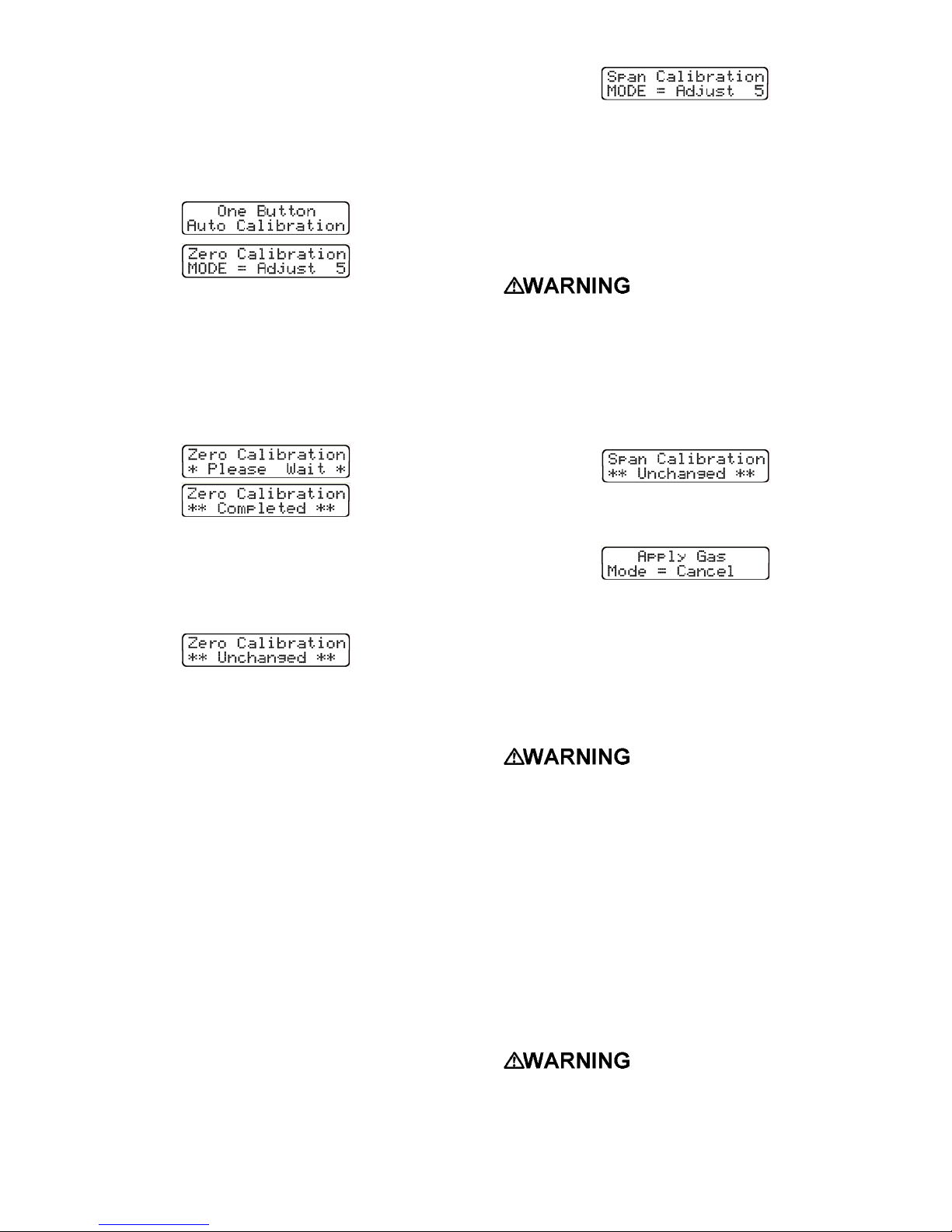
(4) Press the mode button three times within two
seconds. This will "wake up" the instrument
from normal operation, and put it into the “AutoCalibration” mode. A screen will briefly display
the message “One button Auto-Calibration”.
This screen will be followed by the "Zero
Calibration Adjustment” screen.
This screen also includes a timer that counts
down the number of seconds left to initiate the
adjustment.
(5) Press the mode button within five seconds to
initiate the fresh air adjustment. An information
screen will be briefly displayed while the
adjustments are being made, and another when
the adjustments have been completed.
(6) If the mode button is not pushed within five
seconds a fresh air zero adjustment will not be
made. A message screen indicating that the
zero values have not been changed will be
briefly displayed, and the instrument will return
to normal operation.
3.4.1.1 Reading “Too High” or “Too Low” for
zero adjust
To reduce the chances of the PhD Ultra being
inadvertently zero calibrated in contaminated air,
only small adjustments are allowed through the use
of the “One Button” auto-zero sequence. If the
necessary adjustments are too large the display will
indicate the sensor (or sensors) affected, and a
message screen will indicate that the reading is “Too
Low” or “Too High” for zero adjustment. In this case
the instrument must be fresh air zeroed using the
“CAL” button on the instrument keypad and
procedures discussed in Section 3.5.1 of this
manual.
Once the instrument has been successfully zeroed
using the “CAL” button, subsequent calibration
adjustments may be made using the mode button
and “One Button Auto Calibration” logic discussed in
this section.
3.4.2 “Span” auto-calibration sequence
After successful completion of the “zero” autocalibration adjustment the display will show the
“Span Calibration Adjustment” screen.
This screen also includes a timer that counts down
the number of seconds left to initiate the
adjustment.
Note: If the MODE button is pressed at any time
prior to completion of the calibration, the
calibration procedure will be cancelled, no
adjustments will be made and the instrument
will return to normal operation.
Wait at least 3 minutes after
turning the instrument on to allow sensor
readings to stabilize fully before initiating any
calibration procedures. Failure to wait three
minutes before initiating calibration procedures
may lead to inaccurate and potentially
dangerous readings. If a sensor has just been
replaced, the stabilization period may be longer
(see the chart in section 5.1).
(1) Press the mode button within 5 seconds to
initiate “span” auto-calibration. A screen will
instruct you to “Apply Gas”.
The instrument will continue to display this
screen until it determines that calibration gas
has been applied. (Auto-span may be canceled
at any time during the procedure by pressing the
mode button.)
(2) Attach the cylinder of calibration gas, regulator,
short section of tubing and calibration adapter to
the PhD Ultra as shown in Figure 3.4.2.
Make sure the regulator,
cylinder-seating surfaces and threads are clean
and dry before attaching the regulator to the
cylinder of gas. Introduction of contaminants
through the regulator fittings may alter or
degrade the concentration of the gas contained
in the cylinder and may lead to inaccurate and
potentially dangerous gas readings.
CAUTION: The use of regulators with on/off
valves may introduce contaminants into the gas
cylinder and may lead to the breakdown of
reactive gases prior to the cylinder expiration
date. Biosystems strongly recommends the use
of continuous fixed-flow regulators for all
calibration procedures.
Use of non-standard
calibration gas and/or calibration kit
components when calibrating the PhD Ultra may
lead to dangerously inaccurate readings and
may void the standard Biosystems warranty.
29
Page 30
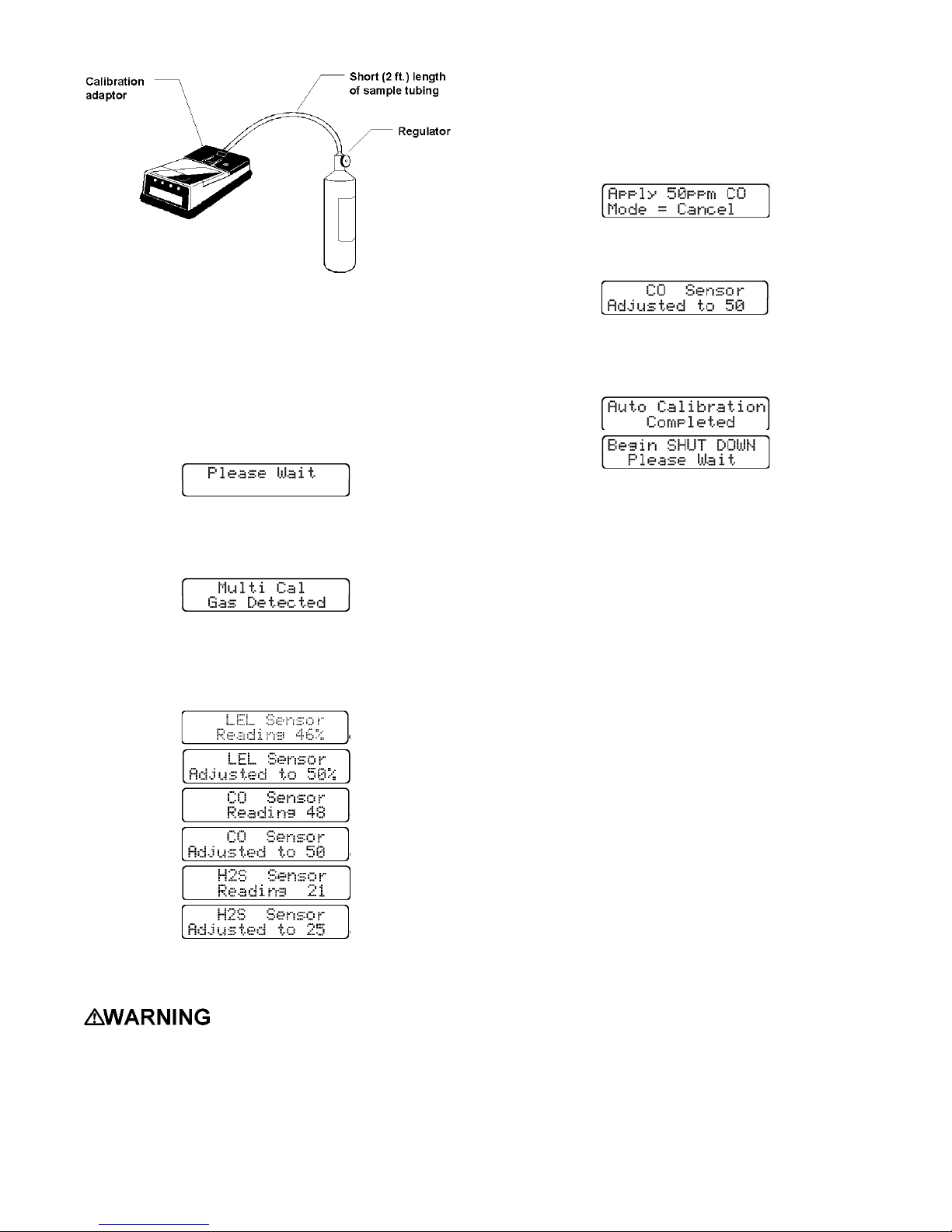
Figure 3.4.2. PhD Ultra calibration setup
The regulator will automatically begin to flow
calibration gas as soon as it is screwed into the
cylinder of gas. Be sure to use a 1.0 liter/minute
regulator with the PhD Ultra.
(3) When the instrument detects that calibration gas
has reached the sensors, the display will show
the message “Please Wait”.
(4) If the instrument determines that the calibration
gas being used is a multi-component mixture
the display will show the message “Multi Cal
Gas Detected”.
The instrument will then show a succession of
screens as each sensor that can be calibrated
using the multi-component mixture is adjusted
in turn. The entire span adjustment process is
automatic.
Note: If multiple cylinders of calibration gas are
used during calibration, it will be necessary to
change cylinders between span adjustments. In
this case the display will indicate the type and
concentration of the next cylinder of calibration
gas to be applied.
When the instrument has detected that the
proper gas has been applied the sensor will be
adjusted.
(6) When all sensors currently installed have been
successfully span adjusted, the display will
announce “Auto Calibration Completed”. The
instrument will then shut itself off.
(7) Remove all fittings from the PhD Ultra, and
press the mode button to turn the instrument on
and resume normal operation.
Note: It is possible to exit the auto-calibration
mode at any time prior to completion by
pressing and holding down the mode button to
turn the instrument off. The instrument will
retain the updated settings for those sensors
whose span adjustments have been completed.
Sensors that were not successfully adjusted at
the time the auto-calibration sequence was
terminated will trigger a “Needs Cal” message at
the time the instrument is next turned on. The
accuracy of those remaining sensors should be
verified by exposure to known concentration
test gas before the instrument is put back into
service.
(5) As each sensor is adjusted the screen indicates
the concentration and type of test gas that is
being used to calibrate the sensor.
Calibration values shown in
the calibration value table must match those
that appear on the calibration gas cylinder(s)
that will be used to calibrate the PhD Ultra. Nonmatching calibration gas and calibration gas
value settings will lead to inaccurate and
potentially dangerous readings.
3.5 Manual calibration procedure
It is also possible to calibrate the PhD Ultra
manually using the four buttons on the instrument
keypad.
3.5.1 Manual fresh air "zero" through
keypad buttons
Note: The manual fresh air “zero” calibration
procedure bypasses the PhD Ultra’s safeguards
against calibration in a contaminated
atmosphere. Be sure to perform this calibration
in an area where the air is known to be fresh.
(1) Turn the instrument on.
(2) Wait at least three minutes after turning the
instrument on to allow sensor readings to
stabilize fully before initiating the fresh air zero
procedure.
30
Page 31
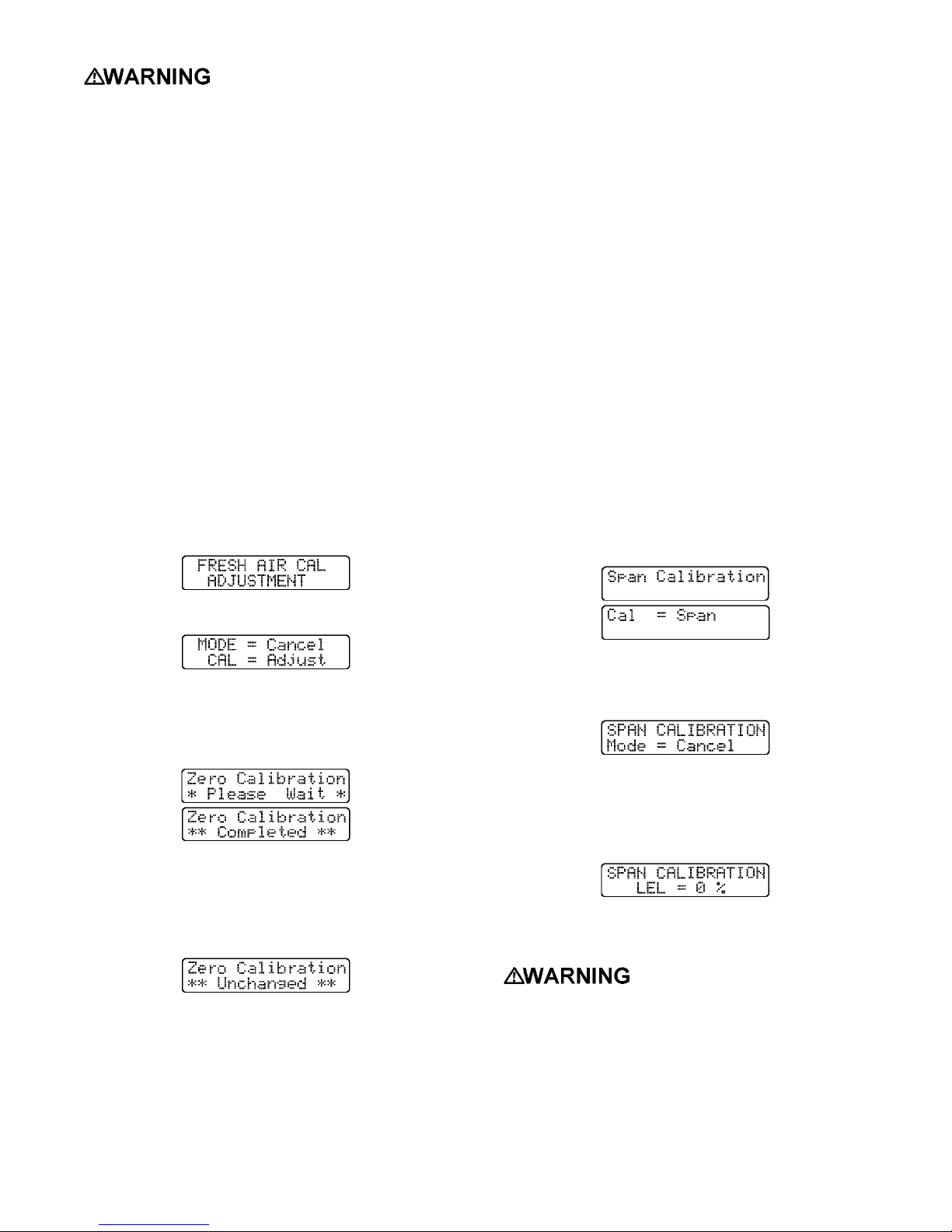
Wait at least 3 minutes after
turning the instrument on to allow sensor
readings to stabilize fully before initiating any
calibration procedures. Failure to wait three
minutes before initiating calibration procedures
may lead to inaccurate and potentially
dangerous readings. If a sensor has just been
replaced, the stabilization period may be longer
(see the chart in section 5.1).
(3) Slide the belt clip towards the rear of the
instrument exposing the four buttons on the
instrument keypad.
(4) Verify that the instrument is in the Basic or
Technician operating mode. To change
operating modes simultaneously hold down the
"+" and"-" keys.
Each time that the operating mode is changed,
the LCD screen will briefly indicate the current
operating mode.
(5) Make sure the instrument is located in an area
where the air is known to be fresh.
(6) Press the keypad button marked "Cal". The
fresh air calibration message will appear briefly
on the instrument LCD.
of only a single sensor is desired. Span calibration
using the keypad buttons may only be done while in
the Basic or Technician operating mode.
(1) Turn the instrument on.
(2) Slide the belt clip towards the rear of the
instrument exposing the four buttons on the
instrument keypad.
(3) Verify that the instrument is in the Basic or
Technician operating mode. To change
operating modes simultaneously hold down the
"+" and"-" keys.
Each time that the operating mode is changed,
the LCD screen will briefly indicate the current
operating mode.
(4) Turn the instrument off by pressing the mode
button for three full seconds until the "release
button" message appears in the screen.
(5) With the unit turned off, press and hold down
the "Cal" button.
(6) While holding down the "Cal" button, press the
mode button to turn the PhD Ultra back on. The
“Span Calibration” message will appear briefly
on the screen. This message is followed by a
screen showing the message “Cal = Span”.
(7) The fresh air calibration message will be
followed by the zero-adjustment screen.
(8) Press "Cal" to automatically zero the instrument.
An information screen will be briefly displayed
while the adjustments are being made, and
another when the adjustments have been
completed.
(9) Pressing the mode button causes the calibration
values in the memory to remain unchanged
from the last time a fresh air adjustment was
made. An information screen will be displayed
briefly which verifies that the zero values have
not been changed.
(10) After completion of the zero adjustment the
PhD Ultra will automatically return to the gas
reading screen display.
3.5.2 Span calibration using keypad
buttons
Span calibration procedures using buttons on the
instrument keypad are most useful when calibration
(7) Press the keypad button marked “Cal” to make
a span adjustment. A screen will briefly display
the message “Span Calibration; Mode =
Cancel”.
Press the mode button at any time to cancel the
calibration mode.
The “Span Calibration” screen will be followed
by another showing the first sensor to be
adjusted.
(8) Attach the cylinder of calibration gas, regulator,
short section of tubing and calibration adapter to
the PhD Ultra as shown in Figure 3.4.2.
Make sure the regulator,
cylinder seating surfaces and threads are clean
and dry before attaching the regulator to the
cylinder of gas. Introduction of contaminants
through the regulator fittings may alter or
degrade the concentration of the gas contained
in the cylinder and may lead to inaccurate and
potentially dangerous gas readings.
31
Page 32
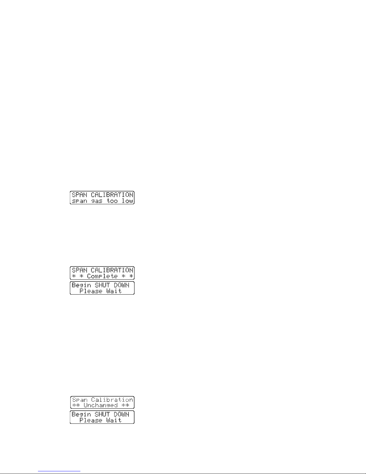
Note: Make sure to use the calibration / sample
draw adapter supplied with the hand aspirated
sample draw assembly. Do not use the battery
operated sample draw pump for this purpose.
(9) A Biosystems standard fixed flow regulator will
automatically begin flowing gas at the correct
flow rate as soon as it is fully screwed in. When
the readings stabilize, use the "+" and "-" keys
to raise or lower the readings to match the
concentration printed on the calibration cylinder
label.
(10) When the span calibration for a particular
sensor is completed, advance to the next
channel by pushing the "Cal" button.
(11) Make sure the correct cylinder of gas is
attached before attempting to adjust the span!
If the concentration of gas reaching the sensor
is too low to allow the instrument to be adjusted,
or if the wrong type of gas is applied to the
sensor being adjusted, a screen will be
displayed indicating that the span gas
concentration is too low.
Verify that the flow rate of the regulator is 1.0
liters per minute. Replace the cylinder, or
choose the correct sensor, and continue.
(12) When span calibration has been completed
for all channels, press and hold the "Cal" button
down until the information screen indicates that
calibration is complete. The PhD Ultra will then
turn itself off.
Note: The “CAL” button must be held down
until the screen indicates that span calibration
has been successfully completed.
If the button is released before this message is
displayed, span values will not be updated, and
remain unchanged from the last time a span
calibration was successfully completed.
Pressing the mode button at any time cancels the
manual span calibration mode. A screen will
announce “Span Calibration Unchanged”. This will
be followed by another announcing “Begin Shut
Down, Please Wait”. The instrument will then turn
itself off.
32
Page 33
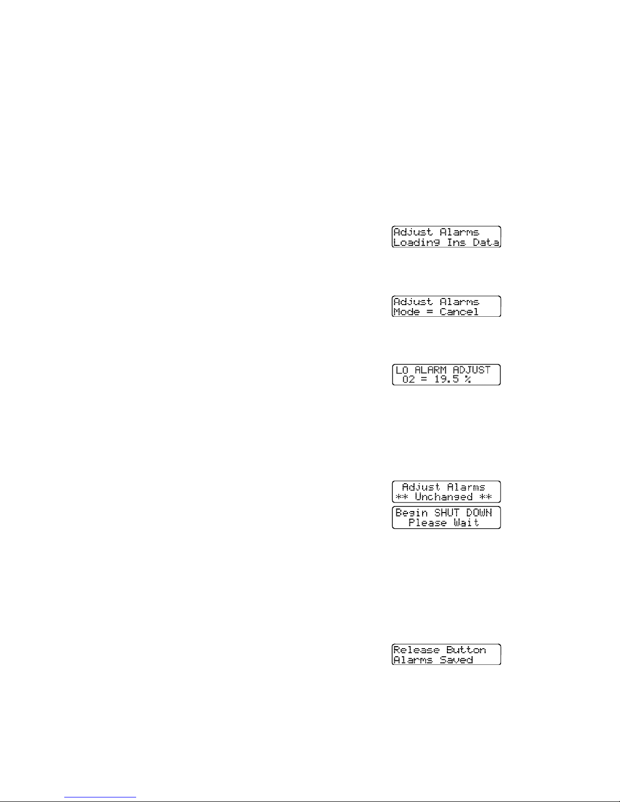
Chapter 4 PhD Ultra Advanced
Functions
PhD Ultra default alarm setting are listed in
Section 5 of Appendix B.
To enter the “Alarm Adjust” mode:
4.1 PhD Ultra advanced features
overview
PhD Ultra microprocessor circuitry makes a number
of advanced features and capabilities possible. The
four buttons located on the instrument keypad may
be used to change alarm set-points, to change the
kind or concentration of calibration gas used during
auto-span calibration procedures, to assign an
instrument ID number, or to make use of other PhD
Ultra optional setup choices.
Use of keypad buttons to setup or reprogram
the PhD Ultra is reserved for authorized
personnel.
These techniques frequently require several buttons
to be pressed and held at the same time.
Caution: Do not press any combination of
buttons other than those listed below. Doing so
may result in the loss of stored data in the PhD
Ultra’s datalogger memory.
4.2 Setting alarm levels
PhD Ultra gas alarms are user adjustable and may
be set anywhere within the range of the sensor
channel. When an alarm set point is exceeded a
loud audible alarm sounds, and an individual bright
red LED alarm light for each affected sensor blinks.
PhD Ultra alarms are normally self-resetting.
Alarms cease as soon as readings drop below the
alarm set point. It is possible, if desired, to set PhD
Ultra alarms so that they "latch". When an alarm
occurs with the alarms latched the visual and
audible alarms will continue even after the
atmospheric hazard has cleared. The instrument
must be manually reset by pressing the mode
button. Pressing the mode button silences the
alarms and returns the instrument to normal
operation.
Procedures for latching PhD Ultra alarms are
given in Section 4.3.
(1) Make sure the instrument is turned off.
(2) Slide the belt clip towards the rear of the
instrument to expose the four buttons on the
instrument keypad.
(3) While holding down the "Alarm" button, press
the mode button to turn the PhD Ultra back on.
The software version screen will be shown
briefly. The screen will then show a number of
screens to indicate that the instrument is loading
sensor and instrument data.
Do not release the “Alarm” button until the
"Adjust Alarms" message appears on the
display screen.
This will be followed by a screen showing the
first alarm point to be adjusted, which is typically
the oxygen sensor alarm.
Note: Pressing the mode button at any time
cancels the “Alarm Adjust” mode. The
instrument will display a screen indicating
“Adjust Alarms, Unchanged”. This screen
will be followed by another announcing
“Begin Shut Down, Please Wait”. The
instrument will then turn itself off.
(5) Press the “CAL” button to advance the display
to the next available alarm adjustment option.
(6) When the desired alarm adjustment has been
reached, use the "+" and "-" keys to raise or
lower the alarm setting.
4.2.1 Alarm adjustment sequence
Note: Factory default settings can be restored at
any time during normal operation by using the
procedures discussed in Section 4.2.2.
In many cases it is possible to comply with OSHA
guidelines while using higher alarm points than
those used by Biosystems. It is important to note
that the default alarm point settings in the PhD Ultra
are very conservative in order to maximize worker
safety.
(7) When all alarm adjustments have been
completed, press and hold the "Cal" button down
until the screen advises you to “Release Button”.
An information screen will indicate when alarm
adjustment is complete. This screen will be
followed by another announcing “Begin Shut Down,
Please Wait”. The instrument will then turn itself
off.
33
Page 34
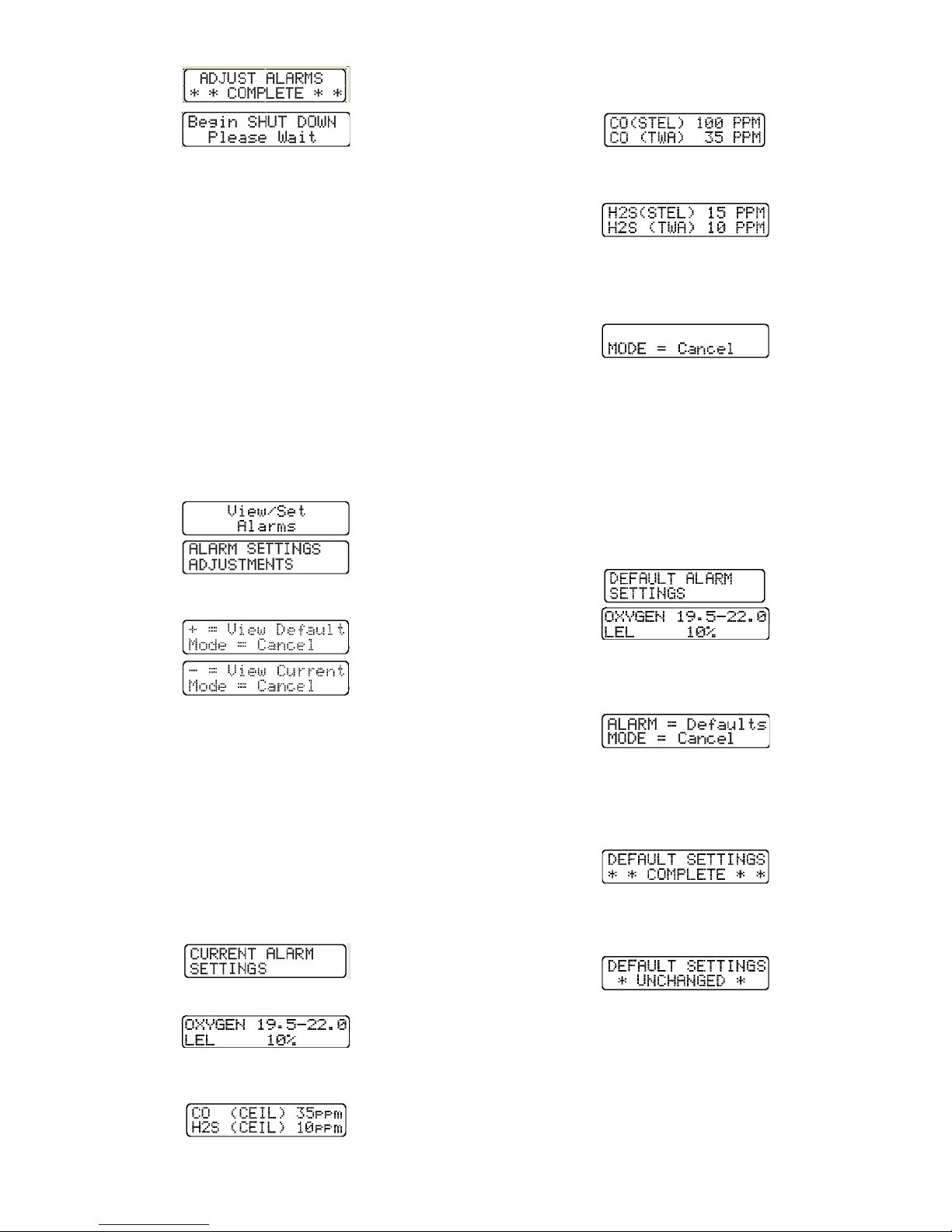
The STEL and TWA alarm set points for the toxic
sensor currently installed in toxic sensor position 1:
4.2.2 Viewing current or restoring the
factory default alarm settings
PhD Ultra alarm settings are set very conservatively
at the factory. (See Appendix B.) Factory default
settings may be restored at any time while the
instrument is being operated in either Basic or
Technician operating mode by doing the following:
(1) Turn the instrument on. Verify that the
instrument is in Basic or Technician operating
mode. Switch modes (if necessary) by
simultaneously holding down the "+" and"-"
keys. Each time that the operating mode is
changed, the LCD screen will briefly indicate the
current operating mode.
(2) Press the "ALM" button on the instrument key-
pad. The display will briefly show the following
screens:
These screens will be followed by two message
screens that will cycle back and forth.
The STEL and TWA alarm set points for the toxic
sensor currently installed in toxic sensor position 2:
The final screen in the sequence shows the
message “Mode = Cancel”. Pressing the mode
button at any time returns the PhD Ultra to normal
operation.
4.2.2.2 Viewing or restoring factory default
alarm settings
(1) Perform steps 1 and 2 above in section 4.2.2.
(2) Press “+” to view the factory default alarm
settings for the sensors currently installed. A
screen will show the message “Default Alarm
Settings”. This screen will be followed by
several more showing the specific alarm
settings for each type of sensor currently
installed.
4.2.2.1 Viewing current alarm settings
(1) Perform steps 1 and 2 above in section 4.2.2.
(2) Press “-” to view the current alarm settings. A
screen will show the message “Current Alarm
Settings”. This screen will be followed by
screens showing the specific alarm settings for
each sensor that is currently recognized. These
screens will be shown in continuous rotation. In
the case of a PhD Ultra with combustible,
oxygen, carbon monoxide, and hydrogen sulfide
sensors installed, the following sequence of
screens would be shown:
Oxygen and combustible gas (LEL):
The ceiling alarm set-points for the toxic sensors
currently installed:
Etc.
The final screen in the sequence shows the
message “Alarm = Defaults, Mode = Cancel”.
These screens will be shown in continuous
rotation.
(3) Press the "ALM" button to restore the default
alarms. The following screen will be shown:
(4) If the mode button is pushed, the current alarm
settings will remain unchanged, and the display
will show the following screen:
(5) After selection of the default or current alarm
settings has been made, the PhD Ultra will
return to normal operation and the display will
revert to the current gas reading screen.
4.3 Instrument setup
The following options are controlled through the
Instrument Setup mode:
34
Page 35
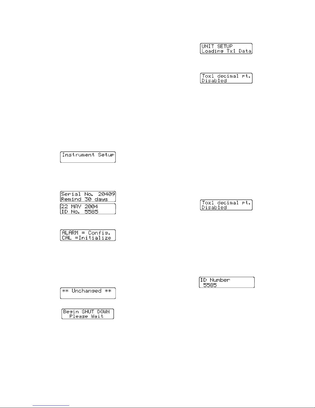
Alarm latch
Security beep,
Toxic sensor decimal point,
Calibration gas settings
User ID number.
The display will briefly show screens indicating the
instrument is loading “Unit Setup” data from the
currently installed sensors.
Each of these options is described in greater detail
below.
To enter Instrument Setup mode:
(1) Make sure the instrument is turned off.
(2) Slide the belt clip towards the rear of the
instrument to expose the four buttons on the
instrument keypad.
(3) While holding down the "+" and “-” buttons,
press the mode button to turn the PhD Ultra
back on.
Do not release the “+” and “-” buttons until
the "Instrument Setup" message appears on
the display screen.
This will be followed by a series of screens
showing the instrument serial number, current
reminder setting, date and instrument ID
number.
The screen will then display the first setup choice,
which is the Tox1 Decimal point.
Press the “CAL” button to advance the display to the
next available setup option or press Mode to exit
from the instrument setup screens.
4.3.2 Changing the precision of the toxic
sensor read-out
The toxic decimal point settings will be the first
screen shown after the PhD Ultra successfully loads
the instrument configuration settings.
The toxic gas read-out may be given in full partsper-million (PPM) increments, or in tenths of partsper-million (0.1 PPM) increments. If the decimal
point is enabled, 0.1 PPM increments will be shown
during normal operation for the specified toxic. If
the decimal point is disabled readings will be shown
in full part per million increments. If the decimal
point is enabled readings will be shown in 0.1 part
per million increments.
This screen will be followed by a screen showing
the first instrument setup choices.
Note: Pressing the mode button at any time will
return the instrument to normal operation. The
instrument will display a screen indicating the
setup is “Unchanged”. This screen will be
followed by another announcing “Begin Shut
Down, Please Wait”. The instrument will then
turn itself off.
p
Press “ALM” to make configuration / setup
choices.
4.3.1 Configuration setup choices
To enter the instrument configuration, follow steps
1-3 in section 4.3 above. Than press the ALM
button.
Pressing the “+” button changes the setting.
Pressing the “CAL” button advances to the second
(Toxic 2) sensor channel.
4.3.3 Assigning an instrument
identification number
To assign the instrument an ID number, first enter
the configuration set up choices menu as described
in section 4.3.1. Then press and release the “CAL”
button to advance to the “ID Number” screen.
Use the “+” and “-” keys to assign any five digit
number between 1 and 25,000. Select "0" if no ID
number is desired. Press the “CAL” button to move
on to the next option.
Note: The instrument serial number is
programmed into the PhD Ultra’s memory and
may not be changed. The instrument ID number
may be set as needed by the user.
4.3.4"Alarm latch" command
To access the alarm latch settings, first enter the
configuration set up choices menu as described in
section 4.3.1. Then press and release the “CAL”
button to advance to the “Alarm Latch” screen.
35
Page 36
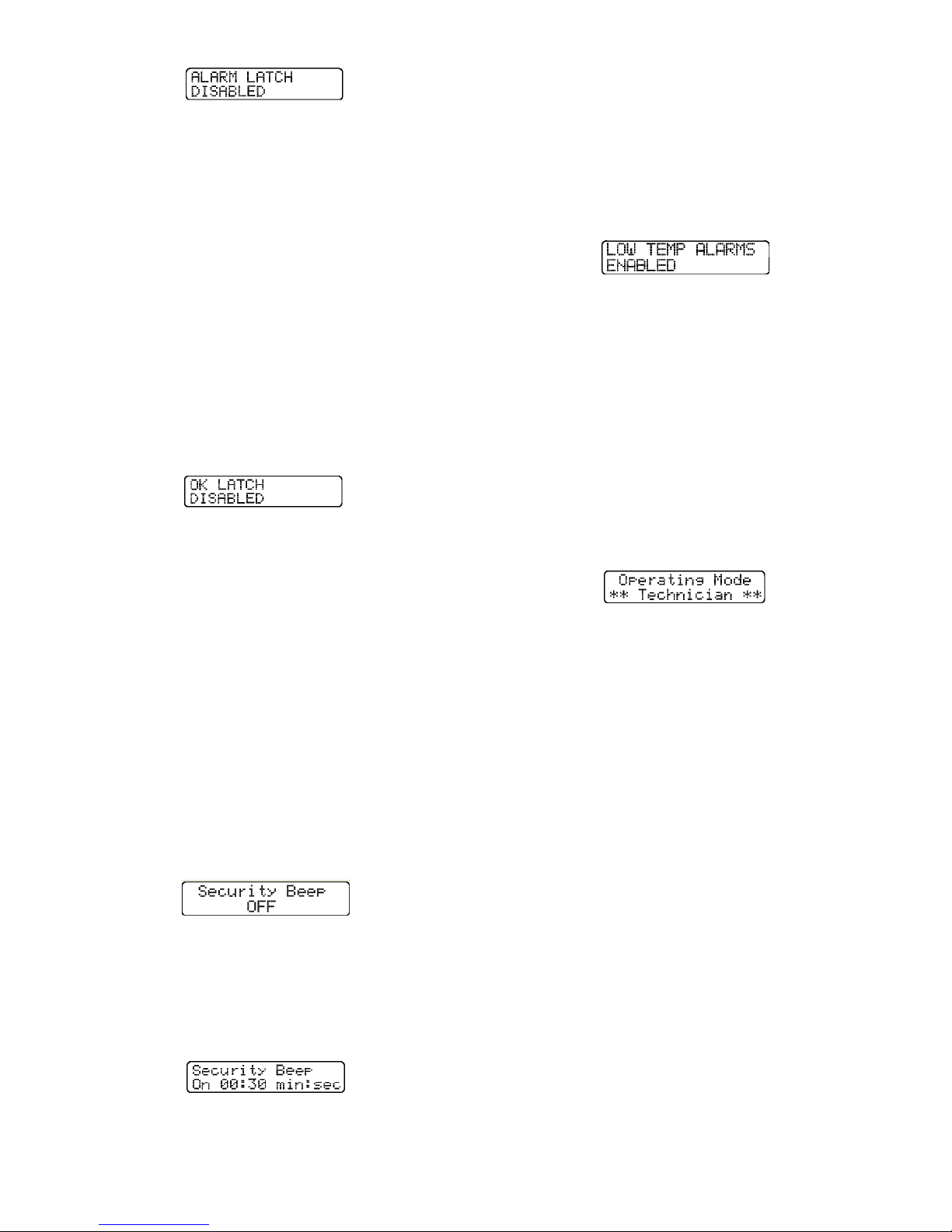
PhD Ultra alarms are normally self-resetting, which
means that the alarms cease as soon as reading
drops below the alarm set point.
PhD Ultra alarms can be configured so that they
"latch”. In the latched condition, once an alarm
occurs both visual and audible alarms continue to
sound even after the atmospheric hazard has
cleared. The instrument must be manually reset by
pressing the mode button. Pressing the mode
button silences the alarms and restores normal
operation.
Press the “+” or “-” key to change the alarm latch
setting.
4.3.5 OK Latch - Text Only mode
To access the OK latch settings, first enter the
configuration set up choices menu as described in
section 4.3.1. Then press and release the “CAL”
button to advance to the “OK Latch” screen.
If an alarm condition occurs and clears while the
PhD Ultra is operated in text-only mode with the OK
latch enabled, the instrument will continue to display
numeric readings for the sensor that was in alarm.
This allows the user to know that an alarm condition
was present during the current operating session.
If an alarm condition occurs and clears while the
PhD Ultra is operated in text-only mode with the OK
latch disabled, the PhD Ultra will automatically
return to the OK display for the sensor that was in
alarm.
Use the “+” or “-” keys to change the “OK Latch”
setting.
4.3.6 Security beep
To access the security beep settings, first enter the
configuration set up choices menu as described in
section 4.3.1. Then press and release the “CAL”
button to advance to the “Security Beep” screen.
The security beep screen allows the PhD Ultra to be
programmed to emit an audible alarm "beep" on a
specified interval while the instrument is in
operation. This periodic beep serves as a reminder
that the instrument is on.
Use the "+" and “-” buttons to turn the security beep
on or off.
and "-" keys to set the interval. (Setting the interval
to “0” will turn the security beep off.)
4.3.7 Low temperature alarms
To access the low temperature alarms settings, first
enter the configuration set up choices menu as
described in section 4.3.1. Then press and release
the “CAL” button to advance to the “Low Temp
Alarms” screen.
The PhD Ultra includes both high and low
temperature alarms for all sensors recognized by
the instrument. The alarm setpoints are preprogrammed into the individual sensor EE-proms
and may not be modified in any way, but the high or
low temperature alarms for all recognized sensors
can be enabled or disabled depending on the needs
of the user.
Press the “+” or “-“ key to change the setting.
4.3.8 Operating mode
To change the operating mode, first enter the
configuration set up choices menu as described in
section 4.3.1. Then press and release the “CAL”
button to advance to the “Operating Mode” screen.
Use the “+” or “-” buttons to choose the operating
mode of the instrument when next turned on in
normal operation.
See section 2.2 above for a detailed description
of operating modes and functions.
4.3.9 Combustible sensor setting
The PhD Ultra may be configured to show
combustible gas readings in terms of percent of LEL
(Lower Explosive Limit) or in terms of the percent by
volume of methane (CH
With the PhD Ultra configured to read in terms of
percent by volume of methane (CH
sensor must be calibrated to the actual percent by
volume of methane used in Biosystems calibration
gas cylinders, not to the %LEL value giv en on the
label. The actual percentage by volume of CH
be stamped in indelible black ink on the side of the
cylinder body. For example, Biosystems popular allin-one mix, part number 54-9044E, with 50% LEL
propane equivalent will list ±1.62% CH
of the cylinder body. In this case, the percent by
volume CH
calibration gas value should be set to
4
1.62%.
).
4
), the LEL
4
will
4
on the side
4
Once the security beep is turned on the screen will
show an additional indicator message showing the
minutes and seconds between beeps. Use the "+"
To change this setting do the following:
(1) Move to the “Instrument Setup” screen as
described in section 4.3.1 and use the ‘CAL’ key
36
Page 37
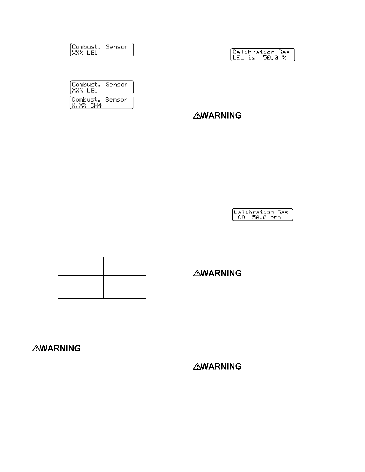
to scroll through the setup options until you
reach the combustible sensor screen.
If an LEL combustible gas sensor has been
installed, the LEL sensor’s calibration gas
concentrations will be the first shown.
(2) Press the “+” or “-“ keys to change the
combustible from reading in LEL to reading in
CH4.
(3) Press and hold the “CAL” key to save changes.
Note: Once the combustible sensor reading has
been changed to %CH4, it will appear as such in
all modes until it is changed back to reading in
LEL.
4.3.9.1 Calibrating the combustible sensor in
mode.
CH
4
With the PhD Ultra configured in the volume %
methane (CH
) mode, the LEL sensor will also be
4
calibrated to the actual volume percent methane
used in Biosystems calibration gas cylinders, not the
%LEL value given on the label. The actual volume
% CH
will be stamped on the side on the cylinder
4
body with indelible ink. For example, Biosystems
popular all-in-one mix of 54-9044E, with 50% LEL
propane equivalent will list 1.62% CH
on the
4
cylinder body. For easy reference, the actual
volume % CH
for the following Biosystems LEL
4
component mixtures is listed in the following table.
LEL Component
Description
50% LEL Methane 2.50
50% LEL Propane
Equivalent
50% LEL Pentane
Equivalent
Table 4.7.2.1 Percent LEL versus volume percent
methane for Biosystems calibration gas cylinders.
Volume %
Methane (CH
1.62
1.25
)
4
4.3.10 Calibration gas concentration
Calibration gas concentration values may be viewed
and adjusted through the instrument set up screens.
Calibration values shown in
the calibration value table must match those
appearing on the calibration gas cylinder(s) that
will be used to calibrate the PhD Ultra. Nonmatching calibration gas and calibration gas
value settings will lead to inaccurate and
potentially dangerous readings.
To adjust the calibration gas concentration:
(1) Move to the “Instrument Setup” screen as
described in section 4.3.1 and use the ‘CAL’ key
to scroll through the setup options until you
reach the “Calibration Gas” screen
This screen indicates the concentration and type
of test gas that will be used to calibrate the
instrument. In the example abov e the screen
indicates that “50 % LEL span gas” will be used.
(2) Use the “+” and “-” buttons to change the
concentration of the gas that will be used.
Calibration values shown in
the calibration value table must match those
appearing on the calibration gas cylinder(s) that
will be used to calibrate the PhD Ultra. Nonmatching calibration gas and calibration gas
value settings will lead to inaccurate and
potentially dangerous readings.
(3) Press the “CAL” button to advance to the
calibration gas that will be used for the next
sensor currently installed. Once again, use the
“+” and “-” buttons to make a change in the
concentration of the calibration gas that will be
used.
(3) Press and hold the “CAL” key to save changes.
4.3.10.1 “CO Plus” sensor calibration gas
screen
The “CO Plus” sensor may be calibrated to either
hydrogen sulfide or carbon monoxide.
Do not use multi-component
calibration gas mixtures containing both carbon
monoxide and hydrogen sulfide when
calibrating a PhD Ultra with a CO Plus sensor
installed. Calibration of the CO Plus sensor
with multi-component calibration gas mixtures
containing both CO and H
S may lead to
2
inaccurate and potentially dangerous readings.
Biosystems multi-component calibration gas
mixtures containing both carbon monoxide and
hydrogen sulfide are labeled as “Not for use
with CO Plus sensors”.
With the CO Plus sensor, the
calibration gas setting determines whether the
instrument is configured for the direct reading
of CO, or for the direct reading of H
S.
2
Calibration gas corresponding to the direct
reading requirement must be used in the
calibration of the instrument. If carbon
monoxide is chosen in the calibration gas
setting option, the display will show CO+ and
carbon monoxide must be used to verify
accuracy. Similarly, if hydrogen sulfide is
37
Page 38
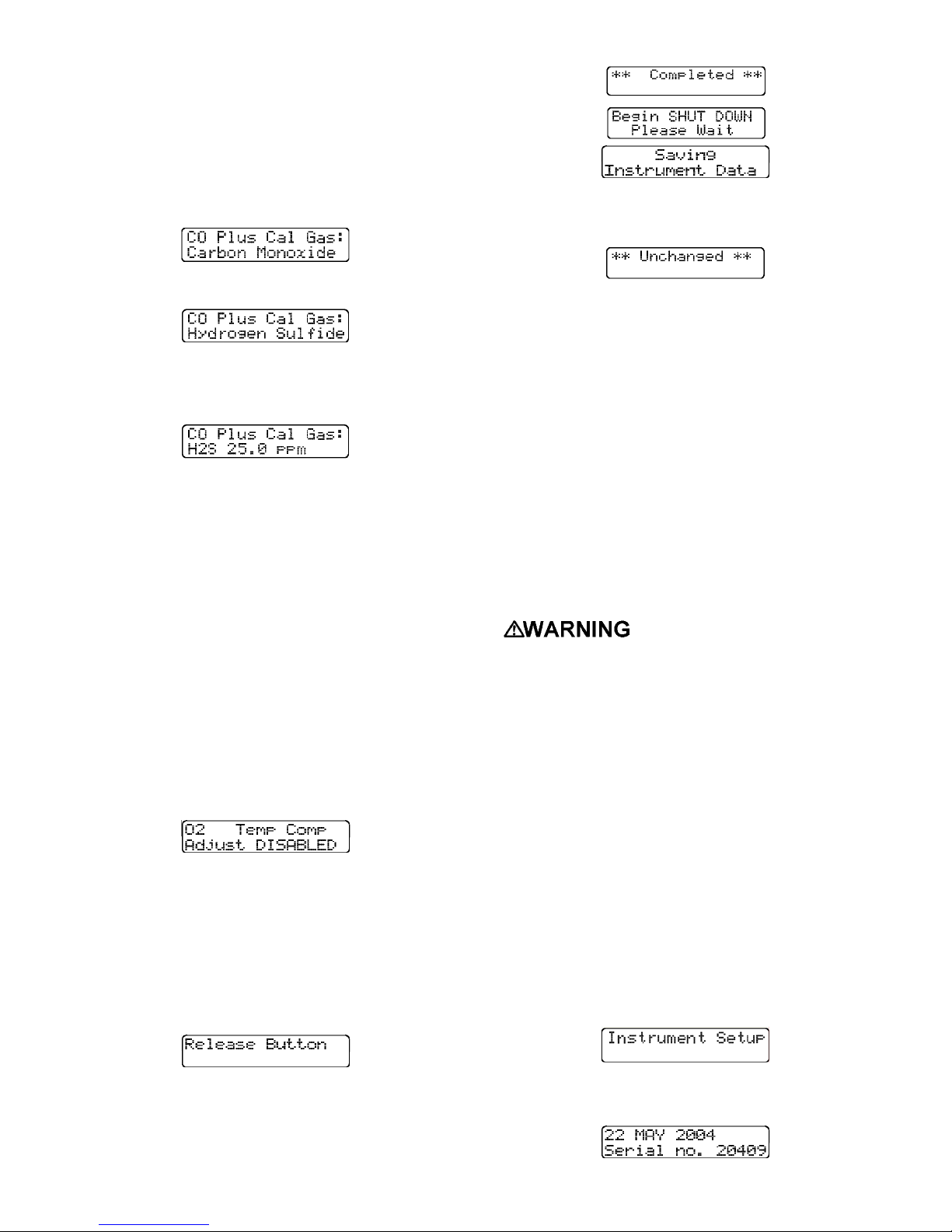
chosen in the calibration gas setting option, the
instrument will display H
sulfide must be used to verify accuracy. Use of
the incorrect calibration gas may lead to
inaccurate and potentially dangerous readings.
S+ and hydrogen
2
If the instrument recognizes a “CO Plus” sensor, the
display will show the “CO Plus Calibration Gas”
screen.
Use the “+” button to change the calibration gas
setting for the “CO Plus” sensor.
Once the appropriate calibration gas selected, press
the “CAL” button to advance to the next screen
showing the concentration of the gas chosen to
calibrate the “CO Plus” sensor.
Use the “+” and “-” buttons to change the
concentration of the gas that will be used.
4.3.11 Temperature Compensation
The PhD Ultra includes built-in temperature
compensation curves that allow the instrument to
give more accurate readings across a broad range
of operating temperatures. Temperature
compensation may be enabled or disabled by the
user as needed.
Note: The default setting for temperature
compensation is enabled. Biosystems
discourages disabling the PhD Ultra’s
temperature compensation.
(1) Move to the “Instrument Setup” screen as
described in section 4.3.1 and use the ‘CAL’ key
to scroll through the setup options until you
reach the “O2 Temp Comp” screen.
The PhD Ultra will then turn itself off.
Pressing mode button to cancel the changes and
save the prev ious configuration.
4.4 Re-initializing the PhD Ultra
During production, all PhD Ultra detectors are
initially setup or programmed with the same
standard or “default” configuration (unless the
purchaser requests otherwise). The default
configuration may be restored at any time by using
the following procedure.
CAUTION:
datalogger memory and cause the instrument to
revert to the default configuration. Verify that
any information needed from the datalogger has
been extracted prior to re-initializing the
instrument. If custom alarm and setup choices
are in use, remember to reset the alarm settings
and optional setup choices immediately
following the re-initialization.
PhD Ultra must be calibrated before being put
back into service. Failure to calibrate the
instrument following re-initialization may result
in inaccurate and potentially dangerous
readings.
To re-initialize the PhD Ultra:
(1) Make sure the instrument is turned off.
(2) Slide the belt clip towards the rear of the
instrument exposing the four buttons on the
instrument keypad.
Re-initialization will clear the
Following initialization, the
(2) Use the “+” and “-” buttons to change the
setting.
4.3.12 Saving changes and exiting the
Instrument Setup mode
When the PhD Ultra is properly configured, press
and hold the “CAL” button to save the changes. The
PhD Ultra will instruct you to release the button after
about 3 seconds.
A screen will briefly announce that changes have
been made and the instrument setup has been
updated.
(3) With the instrument turned off, simultaneously
press and hold down the "+" and “-” buttons.
(4) While holding down the "+" and “-” buttons,
press the mode button to turn the PhD Ultra
back on.
Do not release the “+” and “-” buttons until
the “Instrument Setup” message appears on
the display screen.
The display will then show the release date of
the software currently installed and the userassigned instrument ID number.
38
Page 39
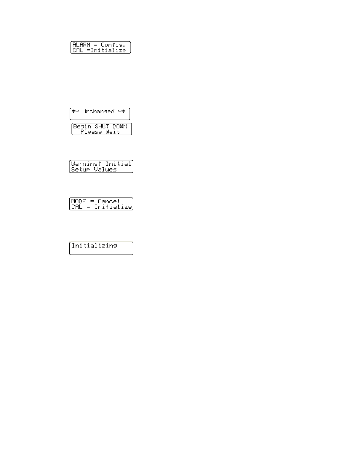
This screen will be followed by a screen showing
the first instrument setup choices.
Note: Pressing the mode button at any time
cancels the Instrument Setup mode. The
instrument will display a screen indicating
setup “Unchanged”. This screen will be
followed by another announcing “Begin
Shut Down, Please Wait”. The instrument
will then turn itself off.
(5) Press “Cal” to begin the re-initialization
sequence. The display will briefly show the
“Initialization Warning” screen.
This screen will be followed by the “Initialization”
screen. Press Mode to cancel the initialization
or
"sessions" when a one minute logging interval is
specified. Using a longer datalogging interval
increases the length of monitoring time for which
data may be stored. For instance, if a datalogging
interval of two minutes is selected 120 hours of
monitoring data may be stored.
Datalogging is a "transparent" function that is
continually in operation. As long as the datalogger
has not been disabled, the instrument will begin
recording data as soon as the instrument is turned
on. The information stored by the datalogger may
be downloaded to a Windows-compatible PC to
create a permanent record, or directly displayed by
the PhD Ultra.
4.5.2 Optional Datalink and Gas Detection
Database Software Kit
Biosystems optional “Datalink” kits allows two-way
communication between your PhD Ultra and an IBM
compatible personal computer. Two kits are
available: The “Datalink Software Kit” (part number
54-05-K0201) includes software, interface cable and
reference manual. The “Datalink Kit” (part number
54-05-K0203) includes software, interface cable and
reference manual as well as a “Datadock” fast
charger / computer interface cradle.
Press Mode to cancel the initialization or press
the "Cal" button to re-initialize the PhD Ultra.
The screen will briefly show the message
“Initializing”.
(7) The instrument will turn itself off when re-
initialization is complete.
4.5 Record keeping
4.5.1 PhD Ultra datalogging overview
Whenev er the PhD Ultra is turned on, the
datalogger automatically records gas readings, turnon / turn-off times, temperatures, battery conditions,
the 8 most recent calibration dates and settings,
types of sensors currently installed, sensor serial
numbers, warranty expiration and service due dates,
temperature compensation curves, and current
alarm settings.
If a sensor is changed or replaced, the PhD Ultra
notes that a change has occurred, displays a “Needs
Cal” message the next time the instrument is turned
back on, and identifies the affected sensors. Even if
the change is only to replace one sensor with
another of the same kind, the PhD Ultra will still
note the change in serial numbers of the sensors
installed, and display the “Needs Cal” message.
The PhD Ultra can store the exposure values for up
to 3,600 data intervals. This is enough for the
storage of up to 60 hours of four gas monitoring
broken into as many as 45 individual monitoring
Datalink software serves two basic functions: getting
stored information out of the instrument and into
your computer, and using files stored in your
computer to setup or "program" your PhD Ultra.
It is important to note that it is not necessary to use
the Datalink software to program your instrument.
Configuration and setup options may be
programmed directly by using the built-in buttons on
the instrument keypad.
On the other hand, Datalink software has been
designed to make programming, downloading, and
data analysis as easy as pushing a button. The
software allows optional instrument setups to be
created by filling out forms right on the computer
screen.
Most functions (such as downloading stored
information from the instrument to your PC, or
uploading configuration setup files from your PC to
the instrument) are automatic.
Once information has been "downloaded" to the
computer, it may be used for a variety of purposes.
Data may be displayed and reviewed in detail
through the computer monitor screen, or used to
automatically generate and print reports, tables and
graphs of time history exposure data. It is also
possible to export records to other software
applications in the form of ASCII text or a
spreadsheet format. Another option is to simply
retain the downloaded records for later use.
Note: The material in this section is primarily
designed to acquaint our customers with
39
Page 40
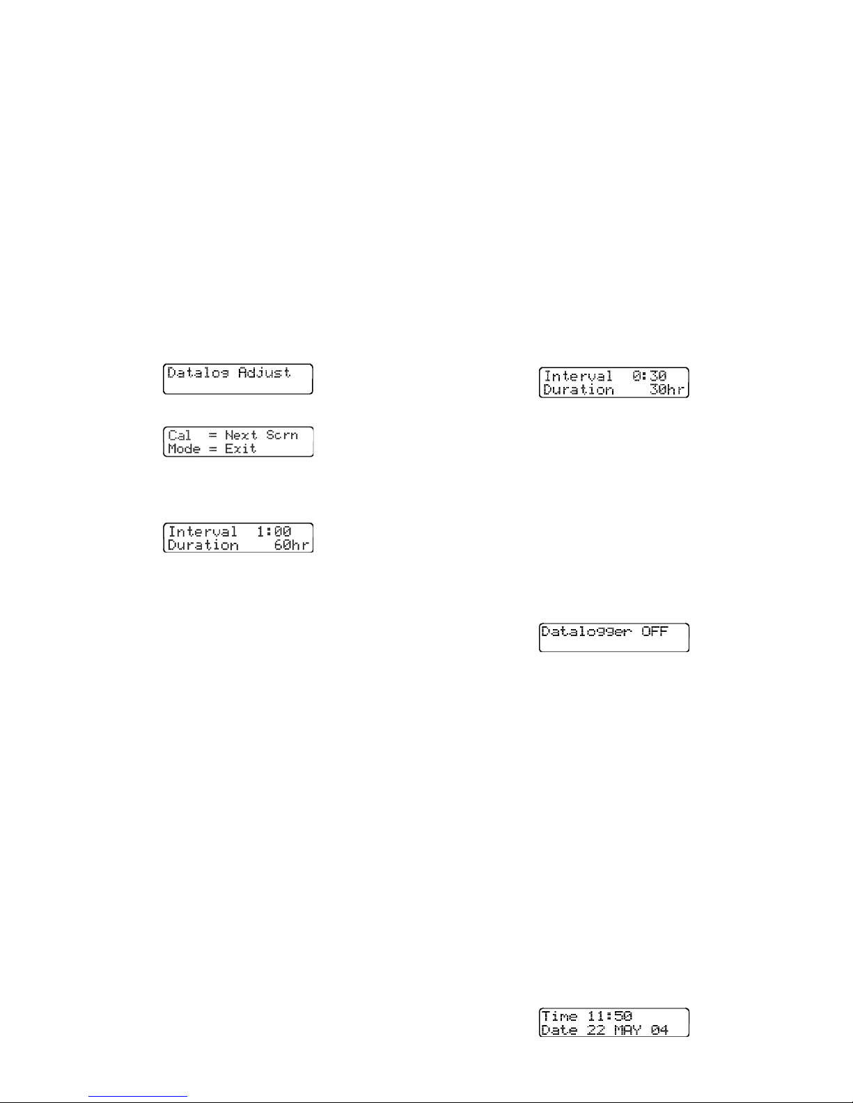
“manual” PhD Ultra setup and download
procedures. Consult the Datalink Reference
Manual for complete instructions in the use of
Datalink software.
4.5.3 Adjusting record keeping parameters
It is possible to customize the way the PhD Ultra
records data in a number of different ways. Options
include extended recording time, tagging the
exposure data with time and date information, or
assigning a location number.
4.5.3.1 Entering the Datalogging Adjust mode
Turn on the PhD Ultra while holding down the "+"
button. (The unit must be in the Technician mode
prior to being turned on.) The Datalog Adjust screen
will briefly appear followed by a screen with further
instructions.
Adjustments to the datalogging interval do not
effect the way in which TWA, STEL, Ceiling, and
Peak exposure values are calculated.
To modify the datalogger interval, first enter the
datalogging adjust mode as described in section
4.5.3.1. Once the interval adjustment screen is
reached, use the “+” and “-“ keys to adjust the
interval to any value between one second and one
hour. The PhD Ultra is capable of logging 3600
points of data. The “Duration” indicates the number
of hours at the current interval setting before the
oldest data will be overwritten by new data. For
instance, using the default datalogger interval
setting of 1 minute will allow 60 hours of data to be
recorded before the PhD Ultra memory is full. If an
interval value of 30 seconds is selected, the
duration will be cut in half, and the memory will be
filled in 30 hours as shown below:
p
Press the Cal key to scroll through the adjustments
that are available. The sample interval adjustment
screen will be the first shown.
4.5.3.2 Adjusting the sampling interval
Whenev er the PhD Ultra is turned on it immediately
begins to monitor, calculate, and log exposure
levels for the atmospheric hazards it is set up to
detect.
The datalogger samples continuously, so the data
stream must be broken into discreet intervals to be
recorded. The datalogging interval defines the
frequency of the breaks in the data stream. The
interval may be set anywhere between one second
and one hour as described below. The default
datalogging interval is 1 minute.
There is a finite amount of memory storage
available in the PhD Ultra. Once the memory is
“full”, the PhD Ultra will begin to write the new data
over the oldest data. In this way, the newest data is
always conserved. Different sensor configurations
and/or datalogging intervals may increase or
decrease the length of time before old data is
overwritten. A longer sampling interval will allow
the retention of more hours of data before old data
is overwritten making the PhD Ultra ideal for longterm sampling projects.
Note: Calculations that are made on an ongoing
basis (i.e. TWA, STEL, Ceilings, and Peak
exposure values) are updated at regular
intervals by the PhD Ultra microprocessor.
Once the memory is “full”, the PhD Ultra will begin
to write the new data over the oldest data. In the
example above, that means that new data will start
replacing old data after 30 hours of monitoring.
Selecting a longer sampling interval will allow more
data to be retained before the oldest data is
overwritten. If an interval of 15 minutes is selected,
the detector is able to log 900 hours of monitoring
data, making the PhD Ultra ideal for long-term
sampling projects.
If datalogging is not desired, reduce the interval
setting to :00:00 to deactivate the datalogger.
To quit and save the new settings press and hold
the “CAL” button. Release the “CAL” button when
the instrument instructs you to release it. The
screen will then show that the datalogger
adjustments have been saved. Pressing the mode
button at any point in the procedure will return the
settings to their former levels. To proceed to other
adjustments, press and release the “CAL” button at
any time.
4.5.3.3 Setting the time and date
To access the time and date settings, first enter the
datalogger adjust mode as discussed in section
4.5.3.1. Then press and release the Cal button
twice to reach the time and date settings. The Time
and Date Screen accesses the PhD Ultra’s internal
real-time clock and calendar date. A cursor will
highlight the value to be adjusted. Pressing the "+"
and "-" buttons will change the value. Pressing the
“Alarm” button will advance the cursor to the next
unit.
40
Page 41
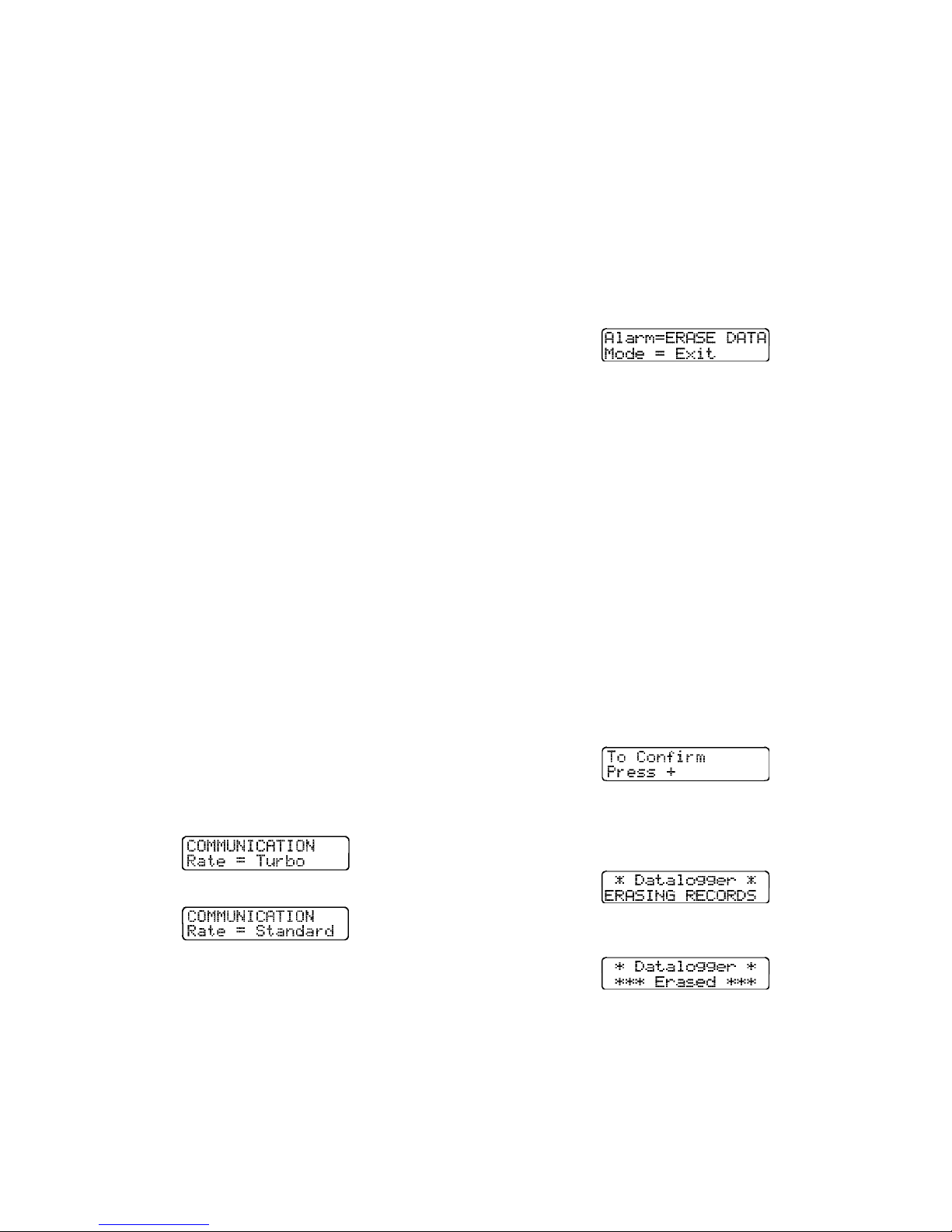
To quit and save the new settings press and hold
the “CAL” button. Release the “CAL” button when
the instrument instructs you to release it. The
screen will then show that the datalogger
adjustments have been saved. Pressing the mode
button at any point in the procedure will return the
settings to their former levels. To proceed to other
adjustments, press and release the “CAL” button at
any time.
4.5.3.4 Setting the communication rate
To access the communications rate settings, first
enter the datalogger adjust mode as discussed in
section 4.5.3.1. Then press and release the Cal
button three times to reach the communications rate
settings. This screen is used to set the speed or
“Baud rate” at which the PhD Ultra sends
information to your personal computer or printer.
There are two communication rate settings, “Turbo”
(38,200 Baud) or “Standard” (9,600 Baud).
Most personal computers are able to transmit and
receive at the higher rate. Since communication at
the slower rate requires a greater amount of time to
download the same amount of data, the “Turbo” rate
should normally be selected.
If the PC is unable to establish communication with
the PhD Ultra at the higher communication rate, the
software is designed to “time out” the attempt, and
display a message on the computer monitor
indicating that the software is “unable to
communicate with instrument”.
Note: At least one additional attempt to
download data should be made before making a
decision to modify the communication rate.
Check all connections before making a second
attempt.
the instrument instructs you to release it. The
screen will then show that the datalogger
adjustments have been saved. Pressing the mode
button at any point in the procedure will return the
settings to their former levels. To proceed to other
adjustments, press and release the “CAL” button at
any time.
4.5.3.5 Clear datalogger memory via pushbuttons
To clear the datalogger memory, first enter the
datalogger adjust mode as discussed in section
4.5.3.1. Then press and release the CAL button
until the following screen is shown:
The PhD Ultra can store the monitoring results for
up to 3,600 data intervals in instrument memory at
any time. When monitoring data is downloaded to a
personal computer, the entire contents of the
memory are transmitted. That means the amount of
time required for downloading is dependent on the
amount of recorded information in the instrument
memory. Once monitoring data has been
successfully downloaded to the PC, there is usually
no reason to retain it in instrument memory.
Caution: Make sure that any session
information that will be needed later is safely
downloaded and stored prior to clearing the
instrument memory. Once session data has
been cleared from the datalogger memory, it will
no longer be retrievable.
Press the “Alarm” button to erase data. The
instrument will display a screen asking you to
confirm that you wish to proceed.
Selecting the “Standard” rate allows successful
communication with nearly all personal computers.
Pressing the “+” and “-” toggles the communication
rate setting between turbo and standard.
pn
Note: Both the PhD Ultra and the Datalink
software must be modified when a change is
made to the communication rate.
If the instrument is set to one rate while the software
is set to the other, proper communication will not be
possible. The software communication rate setting
can be modified through the “PC Setup” screen as
discussed in the PhD Ultra Datalink manual.
To quit and save the new settings press and hold
the “CAL” button. Release the “CAL” button when
Press the “+” button to proceed with clearing the
datalogger. The instrument will display a screen
indicating that the instrument is erasing monitoring
records.
A screen will announce when the datalogger has
been erased.
Note: This procedure only clears data recorded
during monitoring sessions. Alarm settings,
calibration adjustments, user names and
locations and feature settings are not affected
by this procedure.
41
Page 42
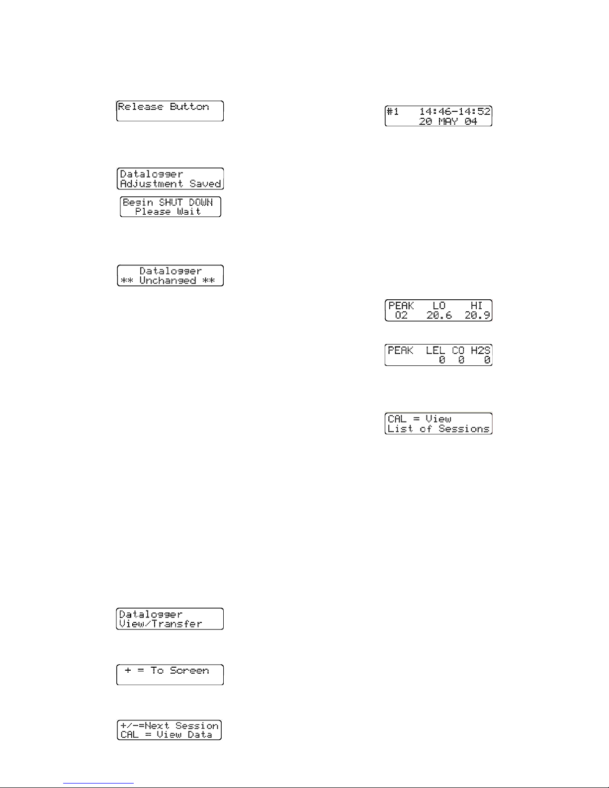
4.5.3.6 Exiting the Datalogging Adjust mode
When the PhD Ultra is properly configured, press
and hold the CAL button to save the changes. You
will be instructed to release the CAL button.
Press “+” to view the most recent monitoring
session. Press “-“ to view the oldest monitoring
session in the datalogger memory. After a few
seconds, the PhD Ultra will automatically show the
most recent monitoring session.
A screen will briefly announce that changes have
been made and the configuration updated. The
PhD Ultra will then shut itself down.
To exit from the datalogger configuration screens
without making or accepting any changes, press the
mode button at any time.
4.5.4 Downloading recorded data
PhD Ultra record keeping capabilities are most
useful when used together with Biosystems’ PC
Based “Datalink” Gas Detector Database Software.
Although downloading the recorded data to a
computer file offers the most complete way to
examine the data, it is not necessary to interface the
instrument with a computer in order to review the
data through the LCD or download directly to a
serial printer. Reviewing recorded data directly
through the instrument display screen allows the
user to answer two very important questions:
(1) Were my workers using their instruments?
(2) Did the atmosphere have any problems?
4.5.4.1 Viewing data
The Record Keeping Data Transfer mode is entered
by turning the PhD Ultra on while holding down the
"-" key. The unit must be in the Technician mode
prior to being turned on to access record keeping.
Change modes if necessary as discussed in
Section 2.2.4.
The Record Keeping Data Transfer screen will be
shown followed briefly.
After a few seconds, the following screen will be
shown:
Press the + button to view data. The display will
briefly shows the following screen.
The numbers in this screen signify the session
number (1), the time the session was started and
completed, (14:46 - 14:52), and the date of the
monitoring session (May 20, 2004). If a location has
been entered, it will also be shown.
Use the "+" and "-" keys to select the appropriate
session, then press the “CAL” button to view the
readings from session "1".
The instrument will automatically cycle between two
peak reading screens, one for oxygen, and one for
the other gases being measured. The oxygen peak
reading screen shows both the high (HI) and low
(LO) readings.
p
Following the peak readings screen for the LEL and
toxic sensors, the PhD Ultra will show the following
screen:
Press “CAL” to return to the list of monitoring
sessions.
Press the mode button at any time to exit the Data
Transfer / Record Keeping mode and turn the PhD
Ultra off.
4.5.5 Entering user ID and monitoring
location identification number
It is possible to assign alphanumeric identification
codes of up to 13 characters each to specify the
user or location name for the monitoring sessions.
This information is automatically added to all
downloaded records and reports for the session.
It is possible to enter up to 10 users and up to 15
locations in the instrument memory by using
Biosystems’ Datalink software to upload the lists
from a personal computer. It is also possible to
modify the current user name and monitoring
location directly through use of buttons on the
instrument keypad.
Once the lists are in the instrument memory it is
possible to “scroll” through the av ailable choices and
either pick the appropriate name and location from
the list. New information may also be entered, but
42
Page 43
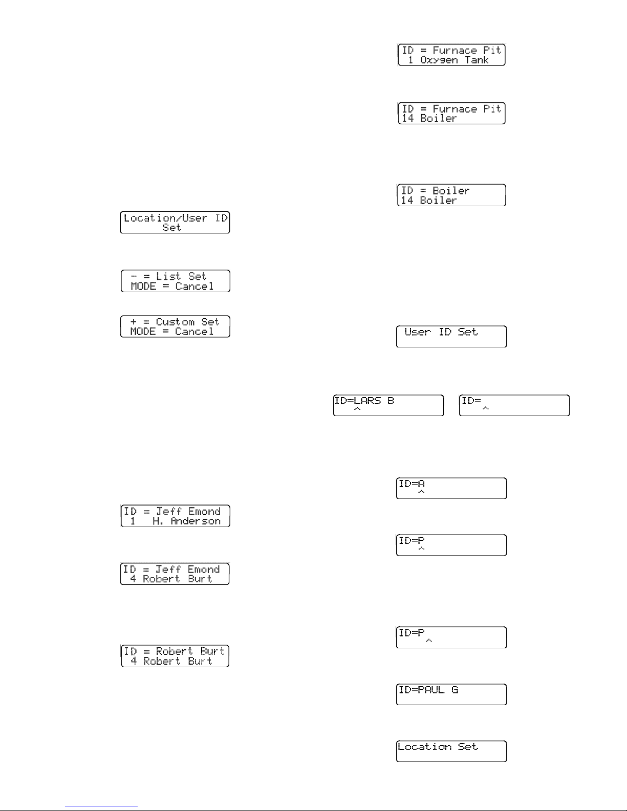
will not be retained in the location or user list for
future use.
This ID feature is available for use while the
instrument is operated in any of the normal
operating modes (Text Only, Basic, or Technician).
Note: Datalink software versions 1.35 and lower
do not support all location / user ID features.
Contact Biosystems to obtain updated software.
Press the "+" key while monitoring in the normal gas
reading screen to review or modify user or location
ID. The PhD Ultra will briefly display the “Set User /
Location” screen.
This instrument will then alternate between the
following two screens:
pn
The "+" and "" keys are used to scroll through the
list. Up to 15 locations may be stored at any time.
When the correct location ID is shown on the bottom
row, press the “ALM” button to make it the current
location. The new current location name will be
displayed on the top row.
Press the mode button to accept the current location
ID and return to normal operation.
4.5.5.2 Custom Set: Enter new or modify user /
location information
Follow the instructions above in section 4.5.5. Then
press the "+" key. The PhD Ultra will briefly display
the “User ID Set” before moving on to the current
user screen.
The “List Set” choice is used to choose from names
and locations already in the instrument memory.
The “Custom Set” choice is used to modify the
“current” user ID or location information.
4.5.5.1 List Set: Select user / location
information from the list
Press the “
” key to display the list of the users
currently in the instrument memory. The first screen
will show the name that the instrument has identified
as the current user on the top row, with the name of
the first user on the list in the instrument memory on
the second row.
The "+" and "" keys are used to scroll through the
list. Up to 10 names may be stored at any time.
When the correct user ID is shown on the bottom
row, press the “ALM” button to make it the current
user. The new current user name will be displayed
on the top row.
If a user has been assigned, the user’s name will be
shown. If a use has not been assigned, the space
after “ID=” will be blank.
or
The arrow on the bottom line indicates the position
of the cursor. The “+” and “-“ keys are used to scroll
through the letters and numbers. Press the “+” key
once and the letter A will be shown.
Continue to use the “+”and “-“ keys until the
appropriate letter or number is shown.
Once the appropriate letter is shown, press the
“ALM” button to move to the next letter to the right.
The cursor will move right by one position. To
move the cursor left by one position, press the ‘CAL”
button.
Once the user ID is set, press the mode button to
display the list of locations currently in the
instrument memory. The first screen will show the
current monitoring location on the top row, with the
name of the first location on the list in the
instrument memory on the second row.
Continue entering the letters until the new name is
shown.
Press the mode button at any time to move on to
the location screens.
43
Page 44
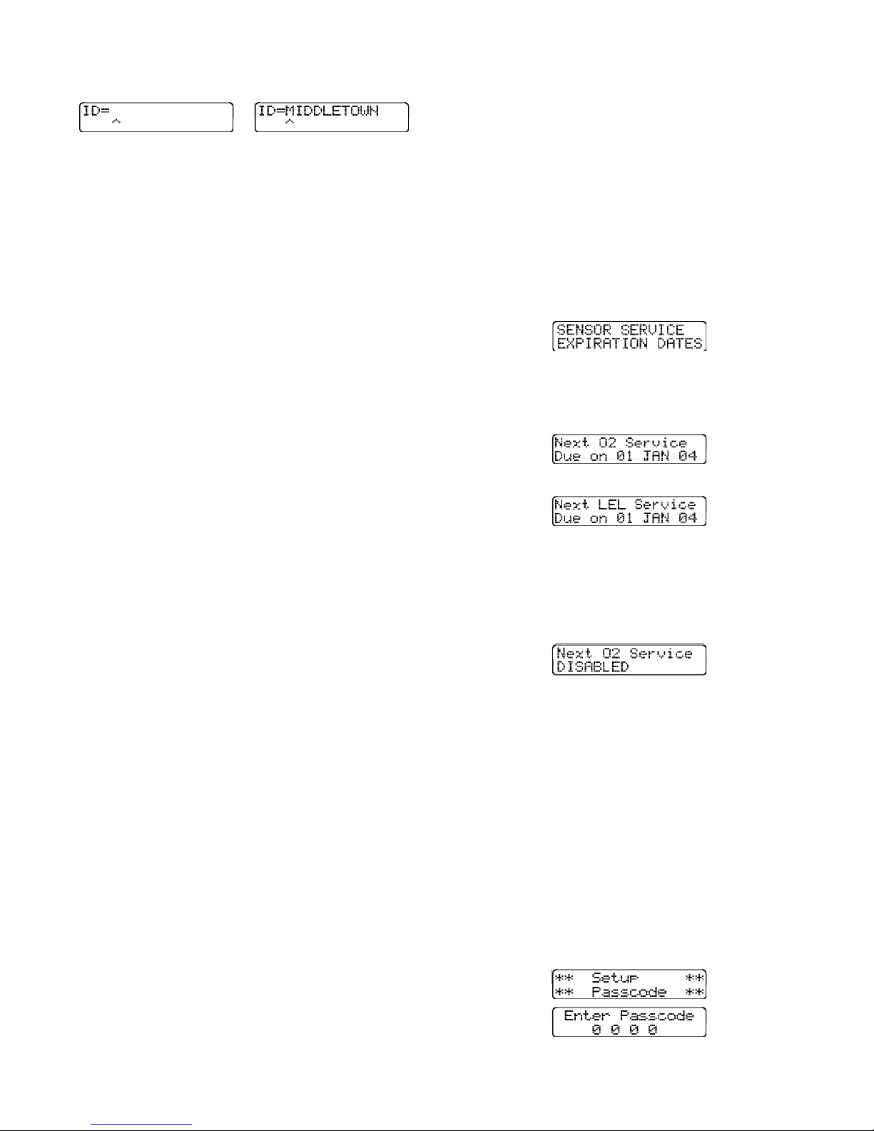
If a location has not been assigned, the screen will
be blank other than showing “ID=”
or
Follow the directions above for the user name and
enter the location name. Once the location has
been entered, press the mode button to save the
monitoring location and return to normal operation.
Note: Only the current user name and
monitoring location can be modified through the
instrument keypad. Modification of the user
name and location lists in instrument memory
requires use of Biosystems’ Datalink Software
and connection with a personal computer as
discussed in the PhD Ultra Datalink Manual.
Service due dates may be reviewed either via
Datalink software or by using buttons on the
instrument keypad to display the dates directly on
the instrument LCD.
Note: It is not possible to assign a new service
due date through the instrument keypad.
Changing or assigning a new service due date
may only by done via personal computer and
PhD Ultra Datalink software.
Service due dates may be reviewed by pressing the
“-” button at any time while the instrument is being
used in a normal operating mode. A screen will
indicate as the instrument begins to display the
assigned dates.
4.5.6 Downloading recorded data to a
computer
PhD Ultra record keeping capabilities are most
useful when used together with Biosystems Datalink
Gas Detector Database Software for use with IBM
compatible Personal Computers. To download data
to a personal computer:
(1) Make sure the PhD Ultra is turned off.
(2) Connect the PhD Ultra Datadock RS-232 cable
to an available COM port on your computer.
(3) Slip the PhD Ultra into the Datadock.
(4) Load Biosystems PhD Ultra Datalink software
on your personal computer.
(5) Choose “Retrieve Data from Instrument” from
the “Datalogger” menu.
(6) The Datalink software will automatically “wake
up” the PhD Ultra, and initiate data transfer.
(7) When downloading is complete the PhD Ultra
will shut itself back off.
Consult the Datalink Owner’s Manual for instructions
on how to review, store and export data, generate
reports, or make use of other advanced features for
the examination and storage of data.
4.5.7 Display “Service Due” dates
PhD Ultra Datalink software may be used to assign
an optional “Service Due” date for each sensor. Any
time after this date is passed a “Service Due”
message will be displayed whenever the instrument
is first turned on. Pressing the mode button
acknowledges the message and allows normal
operation. The message will continue to be
displayed each time the instrument is turned on until
a new service due date is assigned. Since this
information is stored directly with the sensor
EEPROM, a service due alarm will be activated
even if the sensor is removed from one instrument
and installed in another.
This screen will be followed others showing the
assigned service due date for each sensor currently
installed. These screens will continue to be shown
in rotation.
p
p
etc.
If no service due date has been assigned, the
screen will indicate that the warning has been
disabled.
Pressing the mode button at any time returns the
instrument to normal operation.
4.6 Passcode Overview
The PhD Ultra has an option that when enabled,
requires that a passcode be entered before any of
the advanced features or the automatic span
calibration can be activated. This passcode is a 4
digit number which can be set to any number from
“0 0 0 1” to “9 9 9 9”.
To enter passcode options, turn the PhD Ultra on
while holding down both the “+” and “ALM” buttons.
When you hear an audible beep from the alarm let
go of the “+” and “ALM” buttons. The Setup
Passcode screen will be shown briefly followed by
the Enter Passcode screen.
44
Page 45
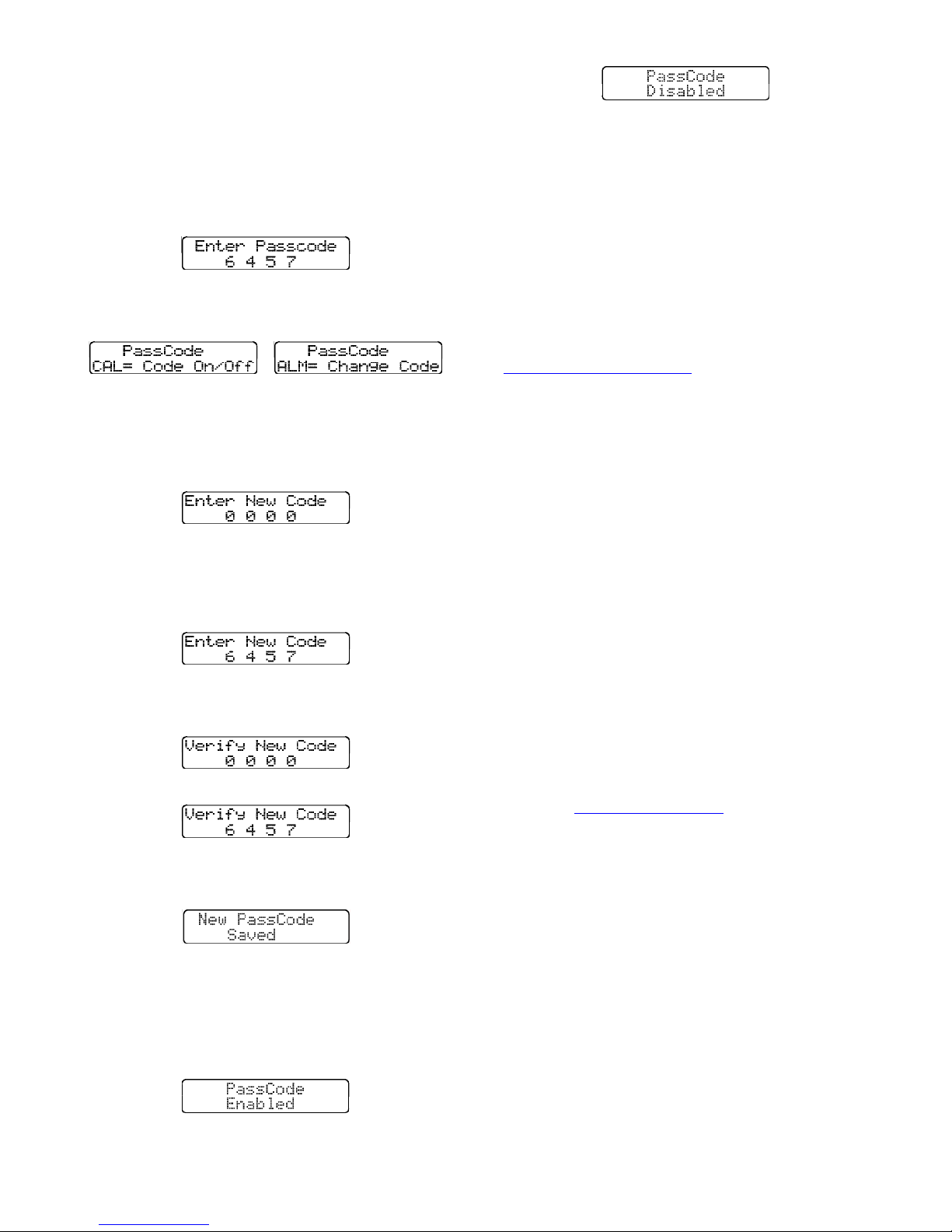
To continue in the passcode setup option, enter the
passcode. If this is the first time entering the
passcode option or the passcode has been saved as
“0 0 0 0”, press CAL to move on to the next screen.
Otherwise, enter the passcode by using the “+” and
“-“ buttons to adjust the digit in each place. The
“ALM” button is used to move from place to place.
The digit which is blinking is the number which can
be modified with the “+” or “-“ button.
Once the passcode has been entered, press the
“CAL” button. The display will toggle back and forth
between the following screens.
4.6.1.1 Changing the passcode
First enter passcode options as described above in
section 4.6. Once the PassCode options are shown,
press ALM. The Enter New Code screen will be
shown.
Enter the new passcode by using the “+” and “-“
buttons to adjust the digit in each place. The “ALM”
button is used to move from place to place. The
digit which is blinking is the number which can be
modified with the “+” or “-“ button.
Once the passcode has been entered, press CAL.
The instrument will prompt you to verify the new
passcode by entering it a second time.
To enable the passcode option press the “+”
button.
Press the “CAL” button to save the new setting.
Press the mode button to cancel. If the mode
button is pressed then a screen will be displayed
which states “Code Setting Unchanged” the
instrument will then shutdown.
4.7 Software / Flash Upload
For instruments with software versions greater than
3.40, the instrument software in the PhD Ultra may
be updated at any time. New software will be
available through the biosystems website at
http://www.biosystems.com
Once the new software is downloaded from the
Internet, it must then be uploaded into the
instrument through the PhD Ultra Datadock.
Note: Instruments with software prior to version
3.40 must be returned to Biosystems for the
software upgrade. Once the instrument is
updated with a version greater than version
3.39, it may then be updated as discussed
below.
CAUTION
will be wiped clean when the new software is
uploaded. Be sure to download any instrument
data that you may need in the future prior to
uploading the new flash.
The Flash download is a two-step download process
that will prepare your PC to update the flash
program of your PhD Ultra. To install the files:
The PhD Ultra’s datalogger memory
.
Enter the new passcode.
Press the “CAL” button to accept. A screen will
quickly appear stating that the new passcode has
been saved.
4.6.1.2 Enable/disable the passcode
To enable or disable the passcode option, first enter
passcode options as described above in section 4.6.
Once the PassCode options are shown, press
“CAL”. The following screen will appear displaying
the current status of the passcode option.
To disable the passcode option press the “-“
button.
1. Close all applications (except the internet
connection) that are currently running on your
computer.
2. Go to www.biosystems.com
Technical Information icon from the entry
screen.
3. Click on Software Downloads.
4. Select PhD Ultra.
5. Follow the directions given on the screen to
download the flash utility program and then the
flash file itself.
45
and select the
Page 46
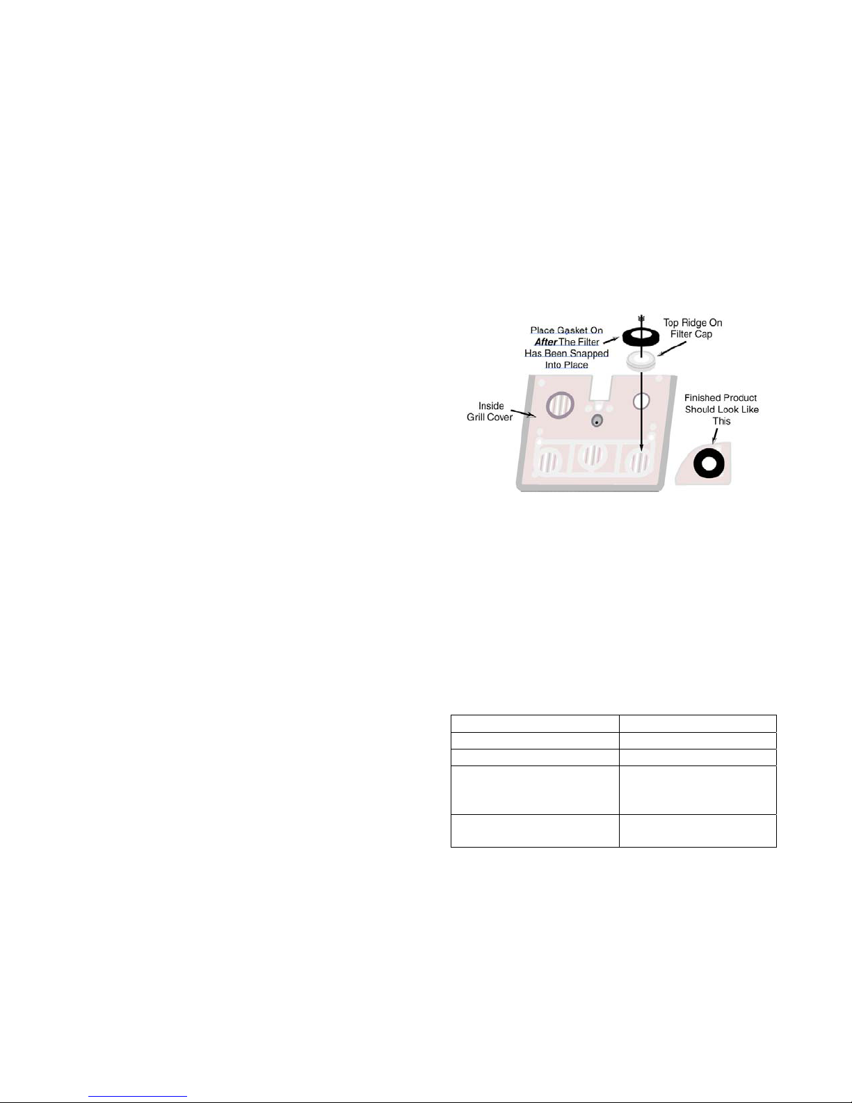
Chapter 5 Trouble-shooting and
repair
Repair procedures may only be performed by
authorized personnel!
5.1 Changing PhD Ultra sensors
The PhD Ultra is designed to recognize the “Smart
Sensors” that are currently installed. Once a sensor
is recognized, the instrument automatically sets
itself up with the appropriate alarm settings for the
sensor. The instrument automatically notices when
changes have been made to the sensors installed
since the instrument was last turned on.
Note: Any changes made to the sensors
installed, even changing one sensor for another
of the exact same type will trigger a “Needs Cal”
message the next time the instrument is turned
on. The PhD Ultra must be recalibrated before
being returned to service following any sensor
change.
The PhD Ultra must be turned off prior to removing
or replacing sensors. A Phillips screwdriver is used
to remove the three screws securing the sensor
cover to the PhD Ultra case.
To replace a sensor:
(1) Make sure the PhD Ultra is turned off.
(2) Remove the three philips screws from the
sensor cover and remove the sensor cover.
For replacement of existing sensors perform
steps A3 and A4.
(A3) From the outer surface of the sensor cover
gently push out, with a flat blade screwdriver,
the metal screen, gasket/spacer, filter/snap ring
assembly in the position above the sensor(s) to
be replaced and discard it. The metal screen is
not to be reused and its absence will not affect
performance.
(A4) Remove any remaining traces of adhesive
from the recessed hole in the sensor cover.
Then proceed to step C5 or D5 depending on
the sensor type.
For first time sensor installation perform steps
B3 and B4.
(B3) From the outer surface of the sensor cover,
push out yellow dust cap with a blunt tool.
(C5) Place the new filter/snap ring assembly, with
ridge side up, onto the recessed hole in the
sensor cover. Firmly press into place. Then
peel the backing paper from the new rubber
gasket and place, adhesive side down, centered
over the newly mounted filter/snap ring
assembly. Now proceed to step 6.
For Reactive Gas Sensors: SO
, ClO2 perform step D5.
Cl
2
, NO2, PH3, HCN,
2
(D5) Place the new teflon spacer onto the
recessed hole in the sensor cover. Firmly press
into place. For optimal sensor response, there
is no sensor cover-mounted, external filter
element used with these sensors. Now proceed
to step 6.
(6) Press the replacement sensor into place.
(7) Replace the sensor cap.
(8) The new sensor must be allowed to stabilize
prior to use. The following chart giv es a
breakdown by sensor type with the required
stability period for current PhD Ultra sensors.
The instrument does not need to be turned on
while new sensors are stabilizing, but
functioning batteries must be installed in the
instrument. If the instrument is a NiCad unit, it
may be placed in a powered charger for the
duration of the stabilization period.
Sensor Stabilization Period
Oxygen (54-04-90) 1 hour
LEL (54-04-80) 5 minutes
All PhD Ultra toxic
sensors except those
15 minutes
shown below
54-04-04 NH3 Sensor
54-04-06 NO Sensor
24 hours
9. The PhD Ultra will automatically recognize the
changes that have been made upon turn on and
display the “Warning Needs Cal” message.
(B4) Remove sensor blank from the sensor
compartment. Then proceed to step C5 or D5
depending on the sensor type.
For Sensors O
, LEL, CO, CO Plus, H2S, NO
2
perform step C5
10. Recalibrate the PhD Ultra with calibration gas
appropriate for the new sensor before the
instrument is put back into service.
PhD Ultra programming includes safeguards to
recognize maladjusted sensors. If the settings on
the new sensor are significantly different from those
of the old it will trigger a message that the sensor is
46
Page 47
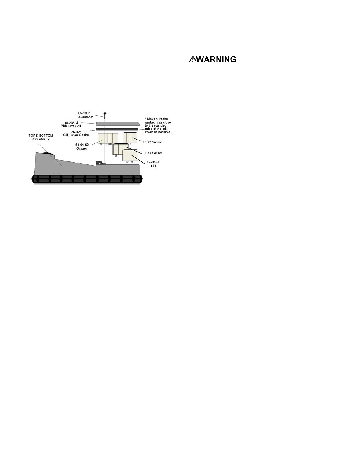
reading “Too Low” or “Too High” for One-Button
Auto-Calibration fresh air adjustment.
Once the new sensor has been fresh-air calibrated
using the “manual” calibration procedure, it will then
be possible to do subsequent fresh air and span
calibrations by using the mode button and OneButton Auto-Calibration procedures.
Note: The first fresh air calibration adjustment
after installation of a new sensor should be
done using the “manual” calibration procedure
as discussed in section 3.5 of this manual.
If the re-boot is unsuccessful and the instrument is a
NiCad model, try the procedure again while the
instrument is connected to a 110 VAC power source
through the battery charger.
The PhD Ultra must be located
in a non-hazardous location during the charging
cycle. Charging the PhD Ultra in a hazardous
location may impair intrinsic safety.
The PhD Ultra is Classified by Underwriters
Laboratories, Inc., the Canadian Standards
Association, and European Community
Certification as to Intrinsic Safety for use in
Hazardous Locations Class I, Groups A, B, C,
and D. This classification is void while the PhD
Ultra is operated while connected to the battery
charger in hazardous areas.
5.2.2 Specific problems
5.2.2.1 Problem: Unit will not turn on
Possible causes:
.
Figure 5.1.1. PhD Ultra sensor compartment cover
and sensors
5.2 Troubleshooting
There are a few troubleshooting and repair
procedures that can be done in the field.
5.2.1 Re-booting the microprocessor
software
Occasionally it may be necessary to re-boot or "cold
start" the PhD Ultra microprocessor software.
Disconnecting the battery, static discharge, or use of
keypad push-buttons in unauthorized combinations
may occasionally cause the microprocessor to
lockup or "crash". In this event it may be necessary
re-boot the microprocessor before the PhD Ultra can
be turned back on and put back into normal
operation.
The most significant symptom of a microprocessor
lock-up is the inability to turn the instrument back on
in the normal manner. The inability to turn the
instrument on may also result from a dead battery.
Make sure the NiCad battery is recharged, or the
alkaline batteries are replaced before attempting
to re-boot.
To re-boot the microprocessor:
(1) Remove the snap-in battery pack. (Make sure
to pull the battery pack completely free from the
instrument.)
(2) Replace the battery pack.
(3) If the re-boot procedure has been successful,
the instrument should resume normal operation.
Battery discharged, microprocessor / software
malfunction.
Solution(s):
Take the instrument to a non-hazardous
location. If equipped with an alkaline battery
pack replace the batteries and attempt to turn
on. If equipped with a rechargeable NiCad
battery pack, plug the PhD Ultra into the battery
charger for several minutes. W ith the
instrument still connected to the battery charger,
attempt to turn the detector on. If this works,
the battery needs to be recharged or replaced.
If the instrument still fails to turn on, re-boot the
microprocessor using the procedures discussed
in Section 5.2.1. If the instrument still fails to
turn on, return to factory for repair.
5.2.2.2 Problem: Unit will not turn off
Possible causes:
Software malfunction, low or bad battery, faulty
on / off mode switch.
Solution(s):
Hold mode button down for thirty seconds. This
should turn the instrument off. Take the
instrument to a non-hazardous location. If
equipped with an alkaline battery pack replace
the batteries and attempt to turn the instrument
back on. If equipped with a NiCad battery pack
plug the PhD Ultra into the battery charger for
several minutes. With the instrument still
connected to the battery charger, attempt to turn
the detector on. If this works, the battery needs
to be recharged or replaced. If the instrument
still fails to turn on, re-boot the microprocessor
47
Page 48

using the procedures discussed in Section 5.2.1.
If the instrument still fails to turn on, return to
factory for repair.
Not in Basic or Technician mode,
microprocessor locked-up or "crashed", loose
connection, switch failure.
5.2.2.3 Problem: Sensor readings unstable in a
known fresh air environment
Possible causes:
Loose connection, bad sensor, improper
calibration, calibration gas has expired.
Solution(s):
Check that the sensor is firmly in place. Check
calibration gas dating. Recalibrate sensor.
Replace sensor if necessary.
5.2.2.4 Problem: "X" appears in place of reading
for sensor
Possible causes:
Sensor failure. Loose connection.
Solution(s):
Check to see sensor is firmly in place.
Recalibrate. Replace sensor if necessary.
5.2.2.5 Problem: Display is blank
Possible causes:
Battery voltage is too low. Operating
temperature is too low. Bad LCD display
assembly. Microprocessor locked-up or
"crashed".
Solution(s):
Take the instrument to a non-hazardous
location. If cold, allow instrument to warm up to
room temperature. If equipped with an alkaline
battery pack replace the batteries and attempt to
turn the instrument back on. If equipped with a
NiCad battery pack plug the PhD Ultra into the
battery charger for several minutes. With the
instrument still connected to the battery charger,
attempt to turn the detector on. If this works,
the battery needs to be recharged or replaced.
If the instrument still fails to turn on, re-boot the
microprocessor using the procedures discussed
in Section 5.2.1. If the instrument still fails to
turn on, return to factory for repair.
5.2.2.6 Problem: No audible alarm
Possible causes:
Loose connection, alarm failure.
Solution(s):
Return to factory for repair.
5.2.2.7 Problem: Keypad buttons (+,-, Cal,
Alarm) don't work
Possible causes:
Solution(s)
Switch to Technician operating mode. Take the
instrument to a non-hazardous location. If
equipped with an alkaline battery pack replace
the batteries and attempt to turn the instrument
back on. If equipped with a NiCad battery pack
plug the PhD Ultra into the battery charger for
several minutes. With the instrument still
connected to the battery charger, attempt to turn
the detector on. If this works, the battery needs
to be recharged or replaced. If the instrument
still fails to turn on, re-boot the microprocessor
using the procedures discussed in Section 5.2.1.
If keypad buttons still fail to function, return to
factory for repair.
5.2.2.8 Problem: Can’t make a “One Button”
auto zero adjustment (LCD shows “Too
High” or “Too Low” for zero adjust)
Possible causes:
The atmosphere in which the instrument is
located is contaminated (or was contaminated at
the time the instrument was last zeroed);
instrument is still attached to calibration fittings;
a new sensor has just been installed; instrument
has been dropped or banged since last turned
on.
Solution(s):
Remove any calibration gas fittings, take the
instrument to fresh air and allow readings to
stabilize. Perform a manual fresh air zero
adjustment using buttons on the instrument
keypad as discussed in Section 3.5.1.
5.3 Changing the PhD Ultra
microprocessor PROM chip
The PhD Ultra is a microprocessor-controlled
design. A Programmable Read Only Memory
(PROM) chip located on the main circuit board is
used to program the instrument. New
microprocessor software versions are installed by
removing the old PROM chip, and replacing it with
the newer version.
Note: PROM chip replacement requires opening
the instrument and removing an electronic
component located on the main circuit board of
the detector. This procedure should not be
done by unauthorized persons. In many cases it
may be better to return the detector to the
factory for this procedure.
To replace the PhD Ultra PROM chip:
(1) Make sure that the PhD Ultra is turned off.
48
Page 49
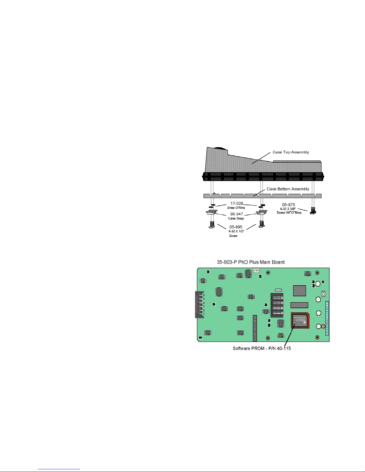
(2) Remove the battery pack.
(3) Remove the sensor grill cover by removing the
three screws on the front of the instrument to
access the sensor compartment.
(4) Gently pull all of the sensors out of their
sockets.
(5) Remove the 6 screws holding the instrument
case together as shown in Figure 5.3.1 and
separate the two halves of the case. (Be careful
to note which screws are equipped with O-rings,
and which are used to secure the weather cover
snaps.)
(6) Carefully remove the main circuit board and
liquid crystal display assembly from the
instrument housing.
(7) Disconnect the three-wire plug that connects the
main board to the audible alarm.
(8) Turn the main circuit board over to locate the
PROM chip in its socket. Note the exact
orientation of the chip in the socket.
Note: The PROM chip is located on the
same side of the main circuit board as the
four light emitting diodes (LEDs) and LCD
ribbon connector. The PROM is located in a
socket near the upper right hand corner of
the board as shown in Figure 5.3.2. The
reference designator (an electronic
component indicator number printed on the
main circuit board) is “U23”.
(9) Use the chip extraction tool supplied with the
replacement PROM to remove the old PROM
chip. (It is usually best to gently rock the tool
back and forth to loosen the PROM from the
socket rather than pulling it straight out.)
Be careful not to crimp any wires as the main
board is reattached.
(12) Reassemble the case, being careful the
protective gasket is properly positioned between
the two sections of the instrument case. Make
sure that all screws, snaps, and O-rings are
properly positioned.
(13) Replace the battery pack.
(14) Re-initialize the PhD Ultra as discussed in
Section 4.4 of this manual.
(15) Verify that all configuration, alarm and
service due settings are correct.
(14) Calibrate the instrument before returning
to service!
Figure 5.3.1. PhD Ultra upper and lower case
assembly
Note: Biosystems strongly recommends use of
a PROM removal tool or "chip puller" to remove
the old PROM. A chip puller should have been
supplied with your replacement PROM. Do not
use small screwdrivers or other nonrecommended devices to remove the old PROM!
Use of non-recommended devices can easily
cause damage to the PROM socket.
Chip pullers are readily available from most
local electronic supply stores or may be
obtained directly from Biosystems.
(10) Insert the new PROM chip into the socket.
Be careful to properly align the flat corner of the
chip with the flat corner of the PROM socket.
(11) Reinstall the main board. Make sure the
ribbon cable connecting the main board to the
meter display board and the audible alarm
connector are properly attached.
5.3.2. PhD Ultra main circuit board (showing
placement of software PROM)
5.4 Motorized pump maintenance
Use of the optional motorized sample draw pump
(part number 54-05-A0101) allows the PhD Ultra to
continuously monitor remote locations. The slip-on
pump obtains power directly from the PhD Ultra
battery, and runs continuously as long as the
instrument is turned on. The instrument constantly
monitors the pump for proper performance. (A
flashing “P” indicator is the upper left corner of the
49
Page 50
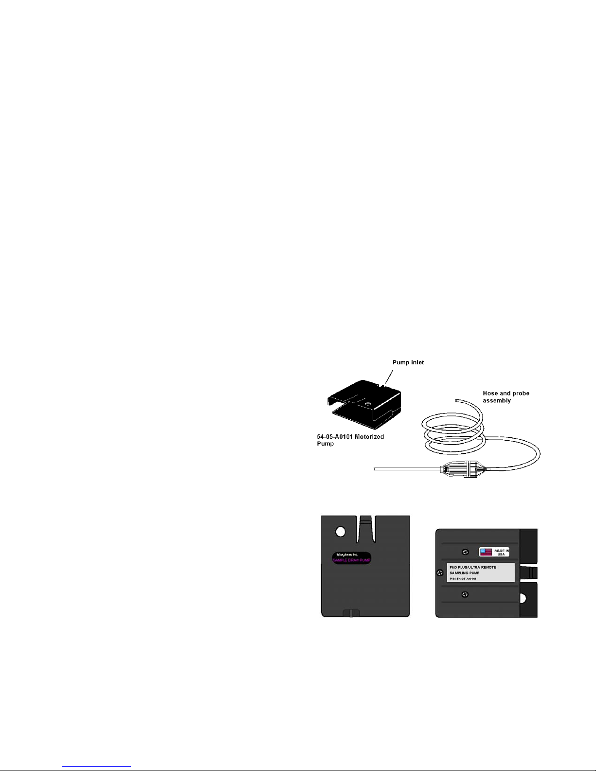
LCD display indicates that the pump is attached and
in normal operation.)
The sample draw pump includes a unique pressure
sensor designed to protect the PhD Ultra from
exposure to water or other liquids. If there is a
change in pressure in the sample draw assembly
due to fluid intake, the pump immediately shuts
down. After a few seconds audible and visual
alarms indicating a low flow condition will also be
activated.
CAUTION: Never perform remote sampling
with the PhD Ultra without the sample probe
assembly. The sample probe handle contains
replaceable filters designed to block moisture
and remove particulate contaminants. If the
pump is operated without the probe assembly in
place, contaminants may cause damage to the
pump, sensors and internal components of the
PhD Ultra.
Procedures for proper use of the motorized
sample pump are contained in Chapter 2.
Replacement of sample probe filters is
discussed in Section 2.4.3.1.
As an additional safeguard, the pump also contains
an internally housed particulate filter. If the pump is
operated without the sample probe assembly in
place, or in particularly dirty atmosphere, this
internal filter can become clogged and periodically
require replacement. Standard accessories
included with every 54-05-A0101 motorized pump
include a package of 10 replacement 61-001 filters.
(1) Attach the pump to your PhD Ultra and turn the
instrument on. Wait for the instrument to
complete the self-test sequence.
(2) Verify that the pump is operating normally, and
that a flashing “P” indicating proper pump
performance may be seen in the upper left hand
corner of the instrument LCD.
(3) Remove the hose and probe assembly from the
pump (if currently attached) then cover the
pump inlet with a finger. If there are no leaks in
the internal pneumatics the pump should go into
a low-flow alarm and shut down, and the audible
and visual low flow alarms should be activated.
A message screen will identify that there is a
low pump flow condition. A second screen will
advise you to remove the blockage and press
“mode” to resume operation.
(4) Press “mode” to reset the pump and continue
the test.
(5) Reattach the hose and probe assembly. Cover
the end of the sample probe tube, and verify
once again that the pump shuts down and that
the low flow alarms are activated.
(6) Press “mode” to reset the pump and resume
normal operation.
5.4.1 Internal pump filter replacement
Use the following procedure for replacing the
internal pump filter:
(1) Remove the three bottom screws from the pump
assembly and disassemble the upper and lower
sections of the pump case as shown in Figure
5.4.3.
(2) Remove the two pieces of tubing from the filter
cap by gently twisting and pulling until the ends
are free.
(3) Remove the filter cap and replace the used 61-
001 filter.
(4) Reattach the filter cap and tubing. Make sure
the tubing is secure to the filter cap before
reassembling the pump case.
(5) Reassemble the upper and lower sections of the
pump case. Do not over-tighten the three
screws!
Proper pump operation must be verified before
the pump is put back into service.
Use the following procedure to verify pump
performance:
Figure 5.4.1. Motorized sample draw pump and
probe assembly
Figure 5.4.2. Top and bottom views of motorized
54-05-A0101 sample pump case
50
Page 51
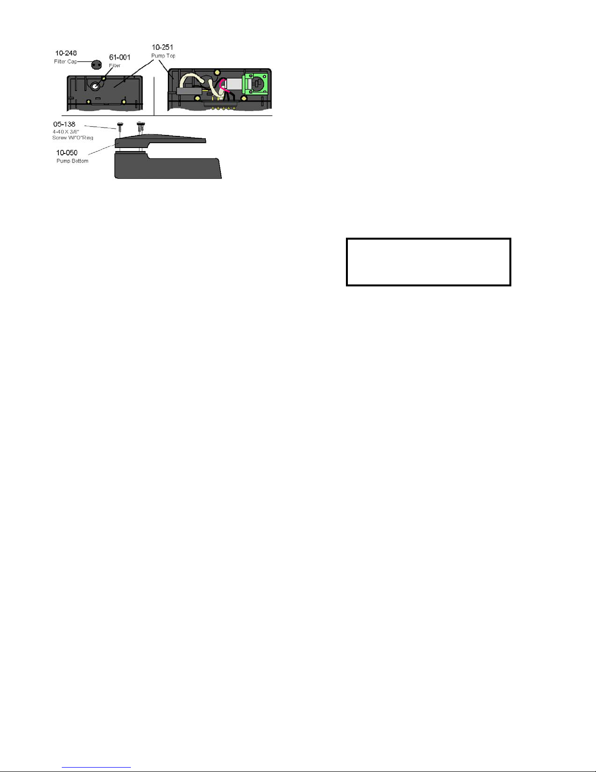
Figure 5.4.3. Cutaway views of 54-05-A0101
motorized pump showing major component
assemblies
5.4.2 Specific problems with motorized
pump
5.4.2.1 Pump will not turn on
Possible causes:
Pump is not properly attached to the instrument.
Instrument is not turned on. Instrument battery
doesn’t have enough power for pump operation.
Note: The return authorization number must be
clearly marked on the outside of the box.
Prominently showing the return authorization
number on the outside of the box ensures that it is
immediately identified and logged into our system at
the time it is received. Proper tracking helps avoid
unnecessary delays in completion of service
procedures.
Note: It is usually best to return the instrument
together with all accessories such as spare
battery packs, chargers, and optional sample
drawing pumps.
Please contact the Biosystems Service
Department at (860) 344-1079 if you require any
additional information.
Thank you for choosing the
PhD Ultra, and thank you for
choosing Biosystems.
Solution(s):
Make sure pump is properly attached to
instrument (it may be necessary to remove the
instrument weather cover until the pump is
attached), recharge or replace instrument
battery pack.
5.4.2.2 Can’t resume normal operation after a
“Low Flow” shut down
Possible causes:
Sample probe or internal pump filters need
replacement, sample hose kinked, sample
probe and probe assembly contains fluids.
Solution(s):
Turn off PhD Ultra, remove pump, disconnect
sample probe and hose assembly, allow any
trapped fluids to drain; replace filters as
necessary, examine hose to make sure there
are no kinks blocking normal flow.
5.5 Returning your PhD Ultra to
Biosystems for service or repair
Please contact the Biosystems Serv ice Department
at (860) 344-1079 to obtain a “Return Authorization”
number prior to shipment. A Biosystems Service
representative will record all relevant information or
special instructions at that time.
To insure safe transport please use the original PhD
Ultra packing materials, or other packing materials
which similarly protect the instrument and
accessories.
51
Page 52
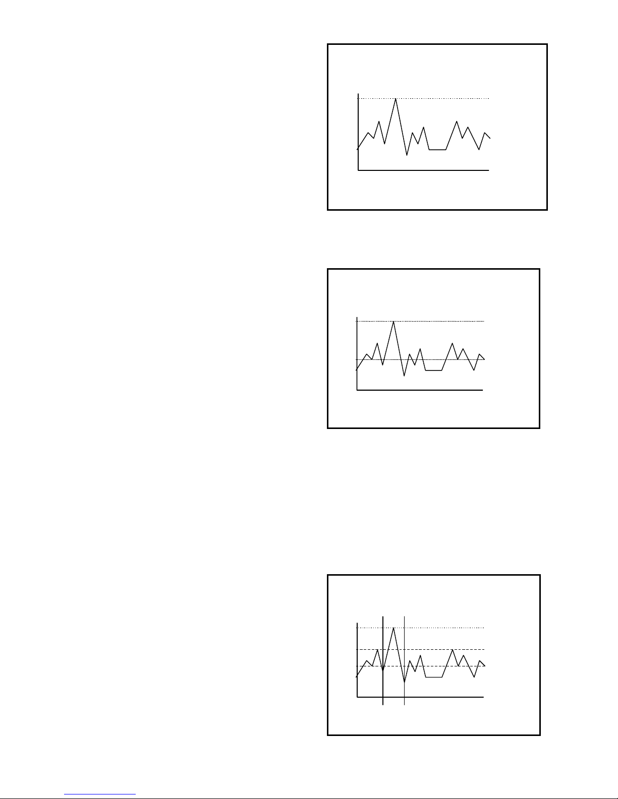
Appendices
Appendix A Toxic gas measurement -
Ceilings, TWAs and STELs
Many toxic substances are commonly encountered in industry. The
presence of toxic substances may be due to materials being stored
or used, the work being performed, or may be generated by natural
processes. Exposure to toxic substances can produce disease,
bodily injury, or death in unprotected workers.
It is important to determine the amounts of any toxic materials
potentially present in the workplac e. T he amounts of toxic materials
potentially present will affect the procedures and personal protective
equipment which must be used. The safest course of action is to
eliminate or permanently control hazards through engineering,
workplace controls, ventilation, or ot her safety procedures .
Unprotected workers may not be exposed to levels of toxic
contaminants which exceed P ermiss ible Exposure Limit (PEL)
concentrations. Ongoing monitoring is necessary to insure that
exposure levels have not changed in a way that requires the use of
different or more rigorous procedures or equipment.
Airborne toxic substanc es are typically class if ied on the basis of
their ability to produce physiological effects on exposed workers.
Toxic substances tend to produce symptoms in two time frames.
Higher levels of exposure tend to produce immediate (acute) effects,
while lower levels of long-term (chronic) exposure may not produce
physiological symptoms for years.
Hydrogen s ulfide (H2S) is a good example of an acutely toxic
substance which is immediately lethal at relatively low
concentrations. Exposure to a 1,000 ppm (parts per million)
concentration of H2S in air produces rapid paralysis of the
respiratory s ystem, c ardiac arres t, and death within minutes.
Carbon monoxide (CO) is a good example of a chronically toxic gas.
Carbon monoxide bonds to the hemoglobin molecules in red blood
cells. Red blood c ells contaminated with CO are unable to transport
oxygen. Although very high concentrations of carbon monoxide may
be acutely toxic, and lead to immediate respiratory arrest or death, it
is the long term physiological effects due to chronic exposure at
lower levels that take the greatest toll of affected workers. This is
the situation with regards to smokers, parking garage attendants, or
others chronically exposed to carbon monoxide in the workplace.
Expos ure levels are too low to produce immediate symptoms, but
small repeated doses reduce the oxygen carrying capacity of the
blood over time to dangerously low levels. This partial impairment of
the blood supply may lead over time to serious physiological
consequences.
Because prudent monitoring programs must take both time frames
into account, there are three independent expos ure measurements
and alarm types built into the PhD Ultra design.
1. Ceiling level:
OSHA has assigned some, but not all, toxic substances with a
ceiling level. This is the highest concentration of a toxic substance
to which an unprotected worker should ever be exposed, even for a
very short time. Never enter an environment even momentarily
when concentrations of toxic substances exceed the ceiling
level.
Time History Graph
Ceiling
2. Time Weighted Average (TWA):
The maximum average concentration to which an unprotected
worker may be exposed over an eight hour working day. During this
time, STEL and ceiling concentration limits may not be exceeded.
Time History Graph
(8 hour)
Ceiling
TWA
3. Short Term Exposure Limits (STEL):
Toxic substances may have short term exposure limits which are
higher than the eight hour TWA. The STEL is the maximum
average concentration to which an unprotected worker may be
exposed in any fifteen minute interval during the day. During this
time, neither the eight hour TW A or the ceiling concentration may be
exceeded.
Any f if teen minute periods in whic h the average STEL c onc entration
exceeds the permissible eight hour TWA must be separated from
each other by at least one hour. A maximum of four of these periods
are allowed per eight hour shift.
Time History Graph
TWA
Ceiling
STEL
15 Minutes
52
Page 53

Appendix B How to determine where to
set your alarms
1. Oxygen alarms
Two oxygen alarm set points have been provided; one for
low concentrations associated with oxygen deficiencies,
and one for high concentrations associated with oxygen
enrichment.
Oxygen deficiency is the leading cause of worker fatality
during confined space entry. All confined spaces must be
tested for oxygen deficiency before entry. Normal fresh
air contains 20.9 percent O2. Any environment in which
the oxygen concentration is less than 19.5 percent has
been determined by OSHA to be oxygen deficient. The
normal PhD Ultra low-alarm setting for oxygen deficiency
is 19.5 percent.
Common causes of this hazard are bacterial action,
displacement of oxygen by other gases, oxidation
(rusting), consumption (burning), or absorption by
materials such as wet activated carbon.
The PhD Ultra will also alarm for an excess of oxygen.
Too much oxygen in an environment can result in an
increased flammability hazard. The new OSHA
standard for confined space entry (29 CFR 1910.146)
requires that oxygen concentrations not exceed 23.5
percent. The normal setting for the high oxygen alarm is
23.5 percent.
2. Combustible gas alarms
As an environment becomes contaminated with
combustible gases or vapors, concentrations can climb
until they eventually reach ignitable or explosive levels.
The minimum amount of a combustible gas or vapor in
air which will explosively burn if a source of ignition is
present is the Lower Explosive Limit (LEL) concentration.
PhD Ultra combustible gas readings are given in percent
LEL, with a range of zero to one-hundred percent
explosive. The PhD Ultra combustible gas sensor is nonspecific and responds to all combustible gases and
vapors.
Combustible sensors contain two coils of fine wire coated
with a ceramic material to form beads. These two beads
are strung onto the opposite arms of a balanced
Wheatstone Bridge circuit. The "active" bead is
additionally coated with a palladium based material that
allows catalyzed combustion to occur on the surface of
the bead. The palladium catalyst is not consumed in the
combustion reaction, it simply enables it to occur. It is
not necessary for the combustible vapor to be present in
LEL concentrations in order for this reaction to occur.
Even trace amounts of combustible gas present in the air
surrounding the sensor will be catalytically burned on the
surface of the bead.
The "reference" bead lacks the palladium outer coating
but in other respects exactly resembles the active bead.
A voltage is applied across the active and reference
elements, causing them to heat. If combustible vapors
are present, the active bead will be heated by the reaction
to a higher temperature. The temperature of the
untreated reference bead is unaffected by the presence of
gas. The difference between the temperatures of the two
beads will be proportional to the amount of combustible
gas present.
Since the two beads are strung on the opposite arms of a
Wheatstone Bridge electrical circuit, the difference in
temperature between the beads is perceived by the
instrument as a change in electrical resistance.
It is important to note that catalytic "hot bead" type
combustible sensors require the presence of oxygen (at
least 8 - 10 percent by volume) in order to detect
accurately. A combustible sensor in a 100 percent pure
combustible gas or vapor environment will produce a
reading of zero percent LEL.
The amount of heat produced by the combustion of a
particular gas on the active bead will reflect the "Heat of
Combustion" for that gas. Heats of combustion may vary
from one combustible gas to another. For this reason
readings may vary between equivalent concentrations of
different combustible gases.
A combustible gas and vapor reading instrument may be
calibrated to any number of different gases or vapors. If
an instrument is only going to be used for a single type of
gas over and over again, it is usually best to calibrate the
instrument to that particular hazard. If the instrument is
calibrated to a particular gas it will be accurate for that
gas. This is what is illustrated in Figure 2.1.
CALIBRATION
STANDARD
100
N
RELATIVE
LEL METER
RESPONSE
100
80
60
40
20
20 40 60
A
T
AL LEL NENTRATI
Figure 2.1. Combustible sensor response to the gas
used to calibrate the sensor
Note that in a properly calibrated instrument, a
concentration of 50 percent LEL produces a meter
response (reading) of 50 percent LEL.
The Figure 2.2 illustrates what may be seen when a
combustible reading instrument is used to monitor gases
other than the one to which it was calibrated. The chart
53
Page 54
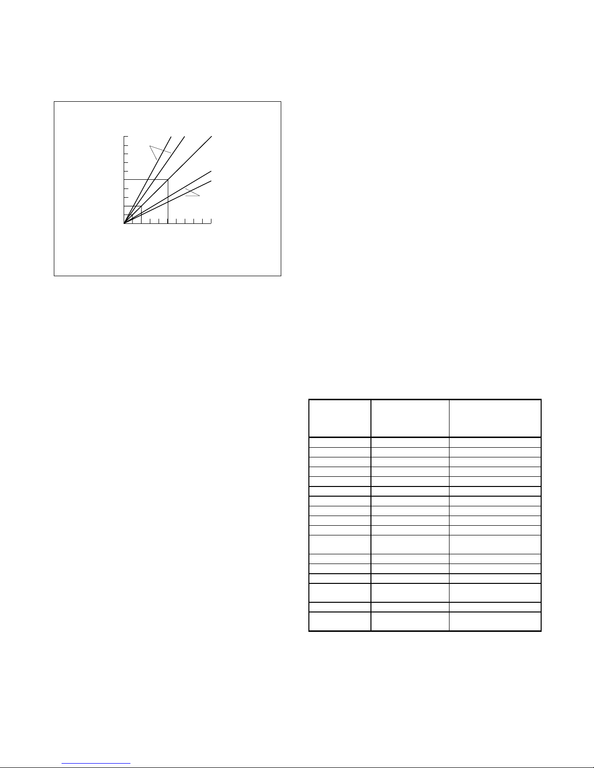
shows the "relative response curves" of the instrument to
several different gases.
STANDARD
1
RELATIVE
LEL METER
RESPONSE
CALIBRATION
OTHER
GASES
80
40
20
4
2
ACTUAL LEL CONCENTRATION
80
OTHER
GASES
100
CALIBRATION
STANDARD
Figure 2.2. Relative response curves
Note that the response to the gas to which the instrument
was calibrated, the "calibration standard”, is still precisely
accurate. For the other gases the responses are a little
off.
In the case of some gases the readings are a little high.
This results in the instrument going into alarm a little bit
early. This type of error is not dangerous, since it results
in workers exiting the affected area sooner than they
absolutely have to.
Gases which produce lower relative readings than the
calibration standard can result in a more potentially
dangerous sort of error. In the chart example above the
"worst case" gas only produces a meter reading of 50
percent LEL even when the actual concentration is 100
percent explosive. If the alarm were set to go off when
the display reads 50 percent LEL, the alarm would sound
simultaneously with the explosion!
If on the other hand the alarm is set to go off when the
display reads 20 percent LEL, a 50 percent concentration
of the same "worst case" gas is enough to cause an
alarm.
It may be seen from the graph that the amount of relative
error decreases the lower the alarm point is set. If the
alarm point is set at 10 percent LEL, the differences due
to relative response of the combustible sensor are
minimal.
When it is not possible to calibrate directly to the gas
to be measured, or when the combustible gas is an
unknown, an alarm set point of 10 percent LEL or
less should be selected.
In the new standard for "Permit Required Confined Space
Entry" (29 CFR 1910.146) OSHA has determined that a
combustible hazard exists whenever the concentration of
combustible gas or vapor exceeds 10 percent LEL. Per
this standard confined spaces with concentrations which
exceed 10 percent LEL may not be entered. Likewise,
workers are required to immediately leave anytime
readings exceed 10 percent LEL.
The standard combustible alarm set-point for the
PhD Ultra is 10 percent LEL.
2.1. Calculating relative responses
There are theoretical ways to estimate the relative
response of a sensor calibrated on one combustible gas
to exposure to another gas. This is done by taking the
actual instrument reading, and multiplying it by a
correction factor.
It is very important to understand that if an error is made
in determining the specific kind of gas present, and the
wrong correction factor is used, the accuracy of the
calculation may be significantly affected.
In actual practice, the relative response varies
somewhat from sensor to sensor.
The response ratios may also shift over the life of a
particular sensor, especially in the event the sensor
loses sensitivity as a consequence of being
“poisoned”.
It is very important to treat gas concentration
calculations based on theoretical relative response
ratios cautiously. Correction factors for PhD Ultra
combustible gas sensors:
Combustible
Gas / Vapor
Hydrogen 0.54 0.83
Methane 0.65 1.0
Propane 1.0 1.5
n-Butane 1.0 1.5
n-Pentane 1.1 1.7
n-Hexane 1.2 1.8
n-Heptane 1.3 2.0
n-Octane 1.6 2.5
Methanol 0.65 1.0
Ethanol 0.76 1.2
Isopropyl
Alcohol
Acetone 0.93 1.4
Ammonia 0.46 0.71
Toluene 1.6 2.5
Methyl Ethyl
Ketone
Ethyl Acetate 1.2 1.8
Gasoline
(Unleaded)
Correction factor
when instrument
is calibrated on
Propane
1.0 1.5
1.2 1.8
1.1 1.7
Correction factor
when instrument is
calibrated on Methane
2.1.1. Using correction factors
As an illustration, consider a PhD Ultra calibrated on
methane, which is then used to monitor ethanol. When
calibrated to methane, the instrument is actually less
54
Page 55

responsive to ethanol than to methane, so the readings
will be low. Multiplying the instrument reading by the
correction factor for ethanol will produce the true
concentration.
Given that the correction factor for ethanol is 1.2, if the
instrument reading is 40 percent LEL, then the true
concentration is seen to be about 48% LEL.
(40 % LEL) X (1.2) = 48% LEL)
Instrument Correction Actual
Reading Factor Concentration
It is important to note that the correction factor for ethanol
is different when the instrument is calibrated on propane.
In the case of a propane calibrated instrument,
instrument readings for ethanol will be high. Given that
the correction factor for ethanol in this case is 0.76; when
the instrument reads 40 percent LEL, the true
concentration for ethanol is 30% LEL.
Biosystems’ “Propane Equivalent” calibration mixtures
are based on methane, but in concentrations which are
designed to produce a level of sensitivity “equivalent” to
that provided by a mixture which contains a 50% LEL
concentration of propane. Because Biosystems’
equivalent mixtures are based on methane, any loss of
sensitivity to methane is detected (and can be corrected)
immediately.
Use of other gases such as pentane or hexane to
calibrate the instrument should be reserved for situations
where these are either the gases predominantly present,
or where the relative response to the calibration gas
closely approximates that of the actual gas to be
measured.
Verifying accuracy before each day’s use insures that
proper sensitivity is maintained over the life of the
combustible sensor.
(40 % LEL) X (.76) = (30% LEL)
Instrument Correction Actual
Reading Factor Concentration
2. Effects of contaminants on combustible sensors
Combustible sensors may be affected by exposure to
silicone containing substances (found in many lubricants
and hydraulic fluids), the tetra-ethyl-lead in "leaded"
gasoline, and halogenated hydrocarbons (Freons£, or
solvents such as trichloroethylene and methylene
chloride). High concentrations of hydrogen sulfide may
also damage the sensor.
If sensitivity of the combustible sensor is lost due to
poisoning, it tends to be lost first with regards to
methane!
A partially poisoned sensor might still respond accurately
to propane while showing a dangerously reduced
response to methane.
2.3. Choosing the right calibration gas for
combustible sensors
The best results are obtained when calibration is done
using the same gas that is expected to be encountered
while actually using the instrument. When not sure what
combustible gases might be encountered, it is important
to choose a calibration gas that will provide a level of
sensitivity which is typical of the widest range of
combustible gases.
Propane provides a sensor response which is more
typical of the wide range of combustible gases and
vapors than any other calibration mixture. The only
drawback to using propane based calibration gas
mixtures is that a partially poisoned sensor might still
respond accurately to propane while showing a
dangerously reduced response to methane.
Use of Biosystems’ “Propane Equivalent” calibration
mixtures guards against this potentially dangerous sort of
calibration error.
3. Toxic gas alarms
The PhD Ultra has three separate alarm points for toxic
gases: Ceiling, STEL, and TWA.
OSHA has assigned some, but not all, toxic substances
with a ceiling or "Peak" exposure level. This is the
highest concentration of a toxic substance to which an
unprotected worker should ever be exposed, even for a
very short time. Never enter an environment even
momentarily when concentrations of toxic substances
exceed the ceiling level.
The Time Weighted Average ( or TWA) is the maximum
average concentration to which an unprotected worker
may be exposed over an eight hour working day. During
this time, STEL and ceiling concentration limits may not
be exceeded.
OSHA has assigned some, but not all, toxic substances
with a Short Term Exposure Limit. The STEL is the
maximum average concentration to which an unprotected
worker may be exposed in any fifteen minute interval
during the day. During this time, neither the eight hour
TWA or the ceiling concentration may be exceeded. Any
fifteen minute periods in which the average STEL
concentration exceeds the permissible eight hour TWA
must be separated from each other by at least one hour.
A maximum of four of these periods are allowed per eight
hour shift.
The table below shows the highest levels at which these
alarms should be set. If OSHA has not determined a
ceiling value, for greatest safety the PhD Ultra ceiling
alarm should be set at the same value as the STEL
alarm. If OSHA has not determined a STEL value, the
PhD Ultra STEL alarm should be set at the same value
as the TWA.
4. U. S. Department of Labor, Occupational Safety
and Health Administration (OSHA) Permissible
Exposure Limits for select toxic gases:
55
Page 56

In the following table "NA" indicates no value has been
assigned by OSHA.
Note: Customers should be aware that OSHA
permissible exposure limits may be subject to
change.
Recent court decisions have affected the
enforcement of permissible exposure limits
published or modified since the initial enactment of
OSHA in 1971. The following table shows the OSHA
permissible exposure limits as published in the 1989
edition of the Code of Federal Regulations (29 CFR
1910.1000). It is recommended that customers verify
that the values given below are correct and current
before using them to update their alarm set-points.
OSHA (1989) Permissible Exposure Limits:
Gas Ceiling STEL TWA
CO 200 ppm NA 35 ppm
H2S NA 15 ppm 10 ppm
SO2 NA 5.0 ppm 2.0 ppm
5. PhD Ultra default alarm settings
The most conservative possible way to set alarms is the
method used by Biosystems for the PhD Ultra default
alarm settings. The Ceiling alarm is set at the factory
at the 8 hour TWA level (when this is given). With this
setting, it is unlikely that either the STEL or TWA alarm
will ever be activated. For other values, contact
Biosystems or your authorized distributor.
Appendix C How to calibrate your PhD
Ultra in contaminated air
Calibration of the PhD Ultra is a two-step process. The
first step is to expose the sensors to contaminate-free air
with an oxygen concentration of 20.9% and perform a
fresh air calibration.
Unfortunately, there are some locations which are never
completely free of contaminants. An example would be a
furnace intensive area which always has a background
concentration of a few ppm CO. To make calibration
easy in this case, it is necessary to use special calibration
"Zero Contaminant" gas. This gas cylinder, Biosystems
part number 9039, is used in conjunction with the sample
draw calibration adapter. Flow the zero contaminant gas
across the sensors for a minute, just as if you were doing
a span calibration. Then do the fresh air calibration steps
described in Chapter 3 of the owners manual.
Gas Ceiling TWA STEL
CO 35 ppm 35 ppm 100 ppm
H2S 10 ppm 10 ppm 15 ppm
SO2 2.0 ppm 2.0 ppm 5.0 ppm
Cl2 0.5 ppm 0.5 ppm 1.0 ppm
HCN 4.7 ppm 4.7 ppm 4.7 ppm
NH3 25 ppm 25 ppm 35 ppm
NO 25 ppm 25 ppm 25 ppm
NO2 1.0 ppm 1.0 ppm 1.0 ppm
Oxygen (O2) Low alarm:
19.5%
Combustible gas 10 % LEL
High alarm:
22.0%
Biosystems PhD Ultra default alarm settings
Note: When a “CO Plus” sensor is installed the
default alarm settings are automatically assigned on
the basis of the calibration gas selected for use. If
carbon monoxide is selected as the calibration gas,
carbon monoxide alarm settings are automatically
assigned. If hydrogen sulfide is selected as the
calibration gas, hydrogen sulfide alarm settings are
automatically assigned.
56
Page 57
Appendix D Suggested Calibration
Gases
Use of non-standard
calibration gas and/or calibration kit
components when calibrating the PhD Ultra can
lead to inaccurate and potentially dangerous
readings, and may void the standard
Biosystems warranty.
Biosystems offers calibration kits and long lasting
cylinders of test gas specifically developed for easy
PhD Ultra calibration. Customers are strongly urged
to use only Biosystems calibration materials when
calibrating their PhD Ultra.
1. Mixtures currently available:
Because combustible gas sensors have different
responses to different combustible gases (see Appendix
B), Biosystems offers several choices for combustible
calibration gas.
Carbon monoxide, sulfur dioxide, and hydrogen sulfide
are all currently available from Biosystems in small (103
or 58 liter), disposable, standard calibration gas
cylinders.
Please note: Biosystems EZ Cal¥ multi-component
calibration gas mixtures are available for use with
many common PhD Ultra detector configurations.
The calibration gas supplied in Confined Space Kits
is normally an all-in-one mixture when one is
available. If an all-in-one mixture is not desired,
please order the PhD Ultra and calibration materials
separately.
Part
Number
54-9045E
54-9041
54-9042E
54-9043
54-9044E
54-9031 Methane (CH4) (2.5%
54-9032 Propane (C3H8)
54-9032E Propane (propane
54-9038 n - Hexane (C6H14)
54-9033 Carbon monoxide
54-9034 Hydrogen sulfide
54-9037 Sulfur dioxide (SO2)
54-9039 Zero air (20.9 %
Calibration gas
mixture
EZ Cal¥ Value Pack
multi-component
calibration gas (CO 50
ppm, propane
equivalent 50% LEL, in
air)
EZ Cal¥ multicomponent gas (CO
50 ppm, methane 50%
LEL, in air)
EZ Cal¥ multicomponent gas (CO
50 ppm, propane
equivalent 50% LEL, in
air)
EZ Cal¥ multicomponent gas (CO
50 ppm, H2S 25 ppm,
methane 50% LEL, in
air )
EZ Cal¥ multicomponent gas (CO
50 ppm, H2S 25 ppm,
propane equivalent
50% LEL, in air )
by volume = 50% LEL
in air)
(1.1% percent by
volume = 50% LEL in
air)
equivalent 50% LEL, in
air)
(0.3% by volume =
25% LEL in air)
(CO) (50 ppm in air)
(H2S) (25 ppm in
nitrogen)
(10 ppm in nitrogen)
oxygen in nitrogen)
Comments
Only for use with 54-12-022
“Value Pack” style fixed f low
rate regulator.
Recommended for general
purpose use for instruments
with CO and LEL sensors
installed.
Not for use with “CO Plus”
sensors.
Not for use with “CO Plus”
sensors. Recommended for
general purpose use for
instruments with CO, H2S
and LEL sensors installed.
Use when monitoring for
pres ence of methane or
natural gas only.
Use when monitoring for
pres ence of propane or
gases with similar response
ratios only.
Recommended for use for
general purpose
combustible gas monitoring.
Use when monitoring for
pres ence of hexane or
gases with similar response
ratios only.
Use for fresh air c alibration
in c ontaminated areas .
57
Page 58

1
Appendix E PhD Ultra Toxic Sensor Cross Sensitivity Data
The table below lists the cross sensitivity of electrochemical toxic sensors used in Biosystems portable gas detectors to
gases other than their target gas. Depending on the nature of the reaction each gas has with the sensor, the effect can
either decrease the signal (negative cross sensitivity) or increase the signal; (positive cross sensitivity). Each figure
represents the reaction of the sensor to 100 ppm of gas, thus providing a percentage sensitivity to that gas relative to its
target gas.
The table below lists the cross sensitivity of electrochemical toxic sensors used in Biosystems portable gas detectors to
gases other than their target gas. Depending on the nature of the reaction each gas has with the sensor, the effect can
either decrease the signal (negative cross sensitivity) or increase the signal; (positive cross sensitivity). Each figure
represents the reaction of the sensor to 100 ppm of gas, thus providing a percentage sensitivity to that gas relative to its
target gas.
CO H2S SO2 NO NO2 Cl2 H
Carbon
monoxide
(CO)
Hydrogen
sulfide (H2S)
“CO Plus”
(Cal to CO)
“CO Plus”
(Cal to H2S)
Sulfur
dioxide
(SO2)
Nitric oxide
(NO)
Nitrogen
dioxide
(NO2)
Chlorine
(Cl2)
100 < 3 0 < 10
< 10 100 < 20 0
100
a 350 a 50 a 25 60 a 40 40 a 40 a 5
25 100
0 0 100 0
0 ~ 35 ~ 5 100 < 40 0 0 0
0
~
20
0
~
20
a 15 a 6 15 a 10 15 a 10 a 1
<
0.5
0 0 120 100 0 0 0 0 0
d - 20
~ 20 ~ 20
~ 100
0 100
< 10 < 40 < 15 0 0 < 100
- 5 0 < 50 0 0 0
|100
HCN HCl NH3 Ethyl-
2
< 0.1 0 0 0 0
0 0 0 0 0
d 15
PH
ene
0 0
3
Hydrogen
cyanide
(HCN)
Phosphine
(PH3)
Ammonia(N
H3)
(-04 Version)
< 3 ~ 600 ~ 395 0
- ~ 25 < 0.1
0 ~ 100 ~ 60 ~ 20 0 ~ 50 0 ~ 5 0 100
1
Data derived in part from City Technology Limited, Product Data Handbook
~
120
58
~
140
0 100 ~ 35 - 5 ~ 25
d 2
Oct. 1, 1992
100
Page 59

Appendix F Calibration
Frequency
One of the most common questions
that we are asked at Biosystems is:
“How often should I calibrate my
gas detector?”
Sensor Reliability and Accuracy
Today’s sensors are designed to provide years of reliable service. In fact,
many sensors are designed so that
with normal use they will only lose 5%
of their sensitivity per year or 10%
over a two-year period. Given this, it
should be possible to use a sensor for
up to two full years without any
significant loss of sensitivity.
A lot of sensors indeed do last that
long with only minimal loss of
sensitivity. However, there are a
number of reasons why a sensor may
unexpectedly lose additional sensitivity
or even fail to respond to gas. Such
reasons include desiccation,
poisoning, physical restriction of
airflow, overexposure, leakage, and
mechanical damage due to dropping
or immersion.
Verification of Accuracy
With so many reasons why a sensor
can lose sensitivity and given the fact
that dependable sensors can be key to
survival in a hazardous environment,
frequent verification of sensor
performance is paramount.
There is only one sure way to verify
that a sensor can respond to the gas
for which it is designed. That is to
expose it to a known concentration of
target gas and compare the reading
with the concentration of the gas. This
is referred to as a “bump” test. This
test is very simple and takes only a
few seconds to accomplish. The
safest course of action is to do a
“bump” test prior to each day’s
use. It is not necessary to make a
calibration adjustment if the readings
are between 90%* and 120% of the
expected value. As an example, if a
CO sensor is checked using a gas
concentration of 50 PPM it is not
necessary to perform a calibration
unless the readings are either below
45 PPM or above 60 PPM.
** The Canadian Standards
Association (CSA) requires the
instrument to undergo calibration
when the displayed value during a
bump test fails to fall between 100%
and 120% of the expected value for
the gas.
Lengthening the Intervals between
Verifications of Accuracy
We are often asked whether there are
any circumstances in which the
period between accuracy checks may
be lengthened.
Biosystems is not the only
manufacturer to be asked this
question! One of the professional
organizations to which Biosystems
belongs is the Industrial Safety
Equipment Association (ISEA). The
“Instrument Products” group of this
organization has been very active in
developing a protocol to clarify the
minimum conditions under which the
interval between accuracy checks
may be lengthened.
A number of leading gas detection
equipment manufacturers have
participated in the development of the
ISEA guidelines concerning
calibration frequency. Biosystems
procedures closely follow these
guidelines.
If your operating procedures do not
permit daily checking of the sensors,
Biosystems recommends the
following procedure to establish a
safe and prudent accuracy check
schedule for your Biosystems
instruments:
1. During a period of initial use of at
least 10 days in the intended
atmosphere, check the sensor
response daily to be sure there is
nothing in the atmosphere that is
poisoning the sensor(s). The period
of initial use must be of sufficient
duration to ensure that the sensors
are exposed to all conditions that
might have an adverse effect on
the sensors.
2. If these tests demonstrate that it
is not necessary to make
adjustments, the time between
checks may be lengthened. The
interval between accuracy checking
should not exceed 30 days.
3. When the interval has been
extended the toxic and combustible
gas sensors should be replaced
immediately upon warranty
expiration. This will minimize the
risk of failure during the interval
between sensor checks.
4. The history of the instrument
response between verifications
should be kept.
59
Any conditions, incidents,
experiences, or exposure to
contaminants that might have an
adverse effect on the calibration state
of the sensors should trigger
immediate re-verification of accuracy
before further use.
5. Any changes in the environment in
which the instrument is being used,
or changes in the work that is being
performed, should trigger a
resumption of daily checking.
6. If there is any doubt at any time as
to the accuracy of the sensors, verify
the accuracy of the sensors by
exposing them to known
concentration test gas before further
use.
Gas detectors used for the detection of
oxygen deficiencies, flammable gases
and vapors, or toxic contaminants must
be maintained and operated properly to
do the job they were designed to do.
Always follow the guidelines provided
by the manufacturer for any gas
detection equipment you use!
If there is any doubt regarding your gas
detector's accuracy, do an accuracy
check! All it takes is a few moments to
verify whether or not your instruments
are safe to use.
One Button Auto Calibration
While it is only necessary to do a
“bump” test to ensure that the sensors
are working properly, all current
Biosystems gas detectors offer a one
button auto calibration feature. This
feature allows you to calibrate a
Biosystems gas detector in about the
same time as it takes to complete a
“bump” test. The use of automatic
bump test and calibration stations can
further simplify the tasks, while
automatically maintaining records
Don't take a chance
with your life.
Verify accuracy frequently!
Please read also Biosystems’ application
note: AN20010808 “Use of ‘equivalent’
calibration gas mixtures”. This
application note provides procedures to
ensure safe calibration of LEL sensors
that are subject to silicone poisoning.
All of Biosystems Applications Notes are
located on the Biosystems website at
http://www.biosystems.com
Page 60
Appendix G Biosystems Standard Warranty Gas Detection Products
General
Biosystems LLC (hereafter Biosystems) warrants gas detectors, sensors and accessories manufactured and sold by
Biosystems, to be free from defects in materials and workmanship for the periods listed in the tables below.
Damages to any Biosystems products that result from abuse, alteration, power fluctuations including surges and lightning
strikes, incorrect voltage settings, incorrect batteries, or repair procedures not made in accordance with the Instrument’s
Reference Manual are not covered by the Biosystems standard warranty.
The obligation of Biosystems under this warranty is limited to the repair or replacement of components deemed by the
Biosystems Instrument Service Department to have been defective under the scope of this standard warranty. To
receive consideration for warranty repair or replacement procedures, products must be returned with transportation and
shipping charges prepaid to Biosystems at its manufacturing location in Middletown, Connecticut, or to a Biosystems
Authorized W arranty Service Center. It is necessary to obtain a return authorization number from Biosystems prior to
shipment.
THIS WARRANTY IS EXPRESSLY IN LIEU OF ANY AND ALL OTHER WARRANTIES AND REPRESENTATIONS,
EXPRESS OR IMPLIED, INCLUDING BUT NOT LIMITED TO, THE WARRANTY OF FITNESS FOR A PARTICULAR
PURPOSE. BIOSYSTEMS WILL NOT BE LIABLE FOR LOSS OR DAMAGE OF ANY KIND CONNECTED TO THE
USE OF ITS PRODUCTS OR FAILURE OF ITS PRODUCTS TO FUNCTION OR OPERATE PROPERLY.
Instrument & Accessory Warranty Periods
Product(s) Warranty Period
PhD5, PhD Lite, PhD Plus, PhD Ultra, Cannonball3, MultiVision, Toxi,
Toxi/Oxy Plus, Toxi/Oxy Ultra, ToxiVision, Ex Chek
Toxi/Oxy Pro, MultiPro 2 years from date of purchase
Toxi Limited
Toxi3Ltd
®
Mighty-Tox
Mighty-Tox 2
Prorated credit is given towards repair or purchase of a new unit of the
same type.
IQ Systems, Series 3000, Airpanel, Travelpanel, ZoneGuard,
Gas9Chek1 and Gas9Chek4
Battery packs and chargers, sampling pumps and other components,
which by their design are consumed or depleted during normal
operation, or which may require periodic replacement
Sensor Warranty Periods
Instrument(s) Sensor Type(s) Warranty Period
PhD Plus, PhD Ultra, PhD5, PhD
Lite, Cannonball3, MultiVision,
MultiPro, ToxiVision, ToxiPro, Ex
Chek
Toxi, Toxi/Oxy Plus, Toxi/Oxy Ultra
O2, LEL**, CO, CO+, H2S
& Duo-Tox
All Other Sensors 1 Year
CO, CO+, H2S 2 Years
All Other Sensors 1 Year
All Others All Sensors 1 Year
** Damage to combustible gas sensors by acute or chronic exposure to known sensor poisons such as volatile
lead (aviation gasoline additive), hydride gases such as phosphine, and volatile silicone gases emitted from
silicone caulks/sealants, silicone rubber molded products, laboratory glassware greases, spray lubricants, heat
transfer fluids, waxes & polishing compounds (neat or spray aerosols), mold release agents for plastics injection
molding operations, waterproofing formulations, vinyl & leather preservatives, and hand lotions which may contain
ingredients listed as cyclomethicone, dimethicone and polymethicone (at the discretion of Biosystems Instrument
Service department) void Biosystems’ Standard Warranty as it applies to the replacement of combustible gas
sensors.
60
As long as the instrument is in service
2 years after activation or 2 years
after the “Must Be Activated By” date,
whichever comes first
3 years after activation or 3 years
after the “Must Be Activated By” date,
whichever comes first
90 days after activation or 90 days
after the “Must Be Activated By” date,
whichever comes first
0 – 6 months of use 100% credit
6 – 12 months of use 75% credit
12 – 18 months of use 50% credit
18 – 24 months of use 25% credit
One year from the date of purchase
One year from the date of purchase
2 Years
 Loading...