

Biostar U8668 Owner's Manual

FCC Information and Copyright
This equipment has been tested and found to comply with the
limits of a Class B digital device, pursuant to Part 15 of the FCC
Rules. These limits are designed to provide reasonable protection
against harmful interference in a residential installation. This
equipment generates, uses and can radiate radio frequency
energy and, if not installed and used in accordance with the
instructions, may cause harmful interference to radio
communications. There is no guarantee that interference will not
occur in a particular installation.
The vendor makes no representations or warranties with respect
to the contents here of and specially disclaims any implied
warranties of merchantability or fitness for any purpose. Further
the vendor reserves the right to revise this publication and to
make changes to the contents here of without obligation to notify
any party beforehand.
Duplication of this publication, in part or in whole, is not allowed
without first obtaining the vendor’s approval in writing.
The content of this user’s manual is subject to be changed without
notice and we will not be responsible for any mistakes found in
this user’s manual. All the brand and product names are
trademarks of their respective companies.

Table of Contents
Notice .............................................................................................1
Mainboard Features ...............................................................2
1. Features Introduction......................................................................... 2
1-1. Hardware............................................................................................................ 2
1-2. BIOS & Software............................................................................................ 6
1-3. Package Contents.......................................................................................... 6
2. Mainboard Configuration................................................................... 7
2-1. Layout of U8668 ............................................................................................ 7
2-2. Component Index ......................................................................................... 8
3. CPU Configuration ............................................................................... 9
3-1. CPU Socket 478 Configuration Steps:............................................... 9
3-2. CPU Fan Header: JCFAN1....................................................................... 10
3-3. System Fan Header: JSFAN1 (Optional) ....................................... 11
4. Jumpers, Headers & Connectors.................................................. 12
4-1. Front Panel Connector: JPANEL1 ....................................................... 13
4-2. ATX 20-pin Power Connector: JATXPWR1 .................................... 15
4-3. ATX 12V Power Connector: JATXPWR2 ......................................... 15
4-4. Hard Disk Connectors: IDE1/IDE2.................................................... 16
4-5. Floppy Disk Connector: FDD1.............................................................. 16
4-6. Wake On LAN Header: JWOL1............................................................ 16
4-7. Clear CMOS Jumper: JCMOS1 ............................................................. 17
4-8. CNR Code Primary/Secondary Selection: JCODECSEL......... 17
4-9. Front USB Header: JUSB3 (with USB1.0 spe) ........................... 18
i

Table of Contents
4-10. 5V / 5VSB Selection for KB: JKBV1 ............................................... 18
5. RAM Module Configuration............................................................. 19
5-1. DDR SDRAM ................................................................................................... 19
5-2. SDRAM............................................................................................................... 20
5-3. How to install DDR/SDRAM DIMM Module ................................... 21
6. Peripheral Port Features ................................................................. 23
6-1. PS/2 Mouse / Keyboard Connector: JKBMS1 ............................. 23
6-2. USB & LAN Port Connectors: JUSBLAN1 ....................................... 24
6-3. Serial and Parallel Interface Ports...................................................... 26
6-4. Game (Joystick/MIDI) Port Connector: JAUD_GAME ............ 29
6-5. Audio Port Connectors: JSPKR1/JLIN1/JMIC1............................ 29
6-6. Audio Subsystem......................................................................................... 30
ii
Chapter 1 Motherboard Description
Notice
Introduction of system
This mainboard is designed to take advantage of the latest industry
technology to provide you with the ultimate solution in data
processing. In the tradition of its predecessors, this mainboard
continues a commitment to reliability and performance and strives
for full compliance and compatibility with industry software and
hardware standards.
U8668 Features:
1.Contains on board I/O facilities that include two serial ports, a parallel
port, a PS/2 mouse port, a PS/2 keyboard port, audio ports, USB
ports and a game port.
2.Contains on board IDE facilities for IDE devices such as hard disks
and CD-ROM Drives.
3.Supports the Intel Pentium ® 4 processor, a leading edge processor.
Complies with PC ATX form factor specifications.
4.Supports popular operating systems such as Windows NT, Windows
2000, Windows ME, Windows XP, Novell, LINUX and SCO UNIX.
1-1
Chapter 1 Motherboard Description
Mainboard Features
1. Features Introduction
1-1. Hardware
CPU:
1.Provides Socket-478.
2.Supports the Intel Pentium ® 4 processor providing the new generation power
for high-end workstations and servers.
Speed:
1.Runing at 400 MHz Front Side Bus frequency.
2.Supports up to 2.4 GHz CPU core speeds.
3.The 33MHz 32 bit PCI 2.2 compliant.
4.The 66MHz AGP 2.0 compliant interface supports 1x, 2x and 4x data transfer
mode.
Chipset:
1.Chipset – VIA VT8751 (P4M266)/ VT8233A.
2.Chipset – Winbond W83697HF.
DRAM Memory:
1.Supports 100MHz or 133MHz SDRAM devices
2.Supports 200MHz, 266MHz DDR SDRAM devices.
3.Supports 64Mb, 128Mb, 256Mb and 512Mb technologies for x8 and 16
devices.
4.Max of 2 Double-Sided DIMMs SDRAM or DDR SDRAM with unbuffered /
Registered.
5.The largest memory capacity is 2 GB.
1-2

Chapter 1 Motherboard Description
Shadow RAM:
Motherboard is equipped with a memory controller providing shadow RAM and
support for ROM BIOS.
Green Functionality:
1.Supports Award BIOS ™ power management functionality.
2.Has a power down timer from 1 to 15 minutes.
BUS Slots:
1.Contains 1 AGP slot.
2.Contains 1 CNR slot.
3. Contains 3 32-bit PCI bus slots
Flash Memory:
1.Supports flash memory functionality.
2.Supports ESCD functionality.
Built in VGA:
1. High Resolution CRT RGB Interface
1.250 MHz RAMDAC on chip with Gamma Correction.
2.Horizontal / Vertical Sync outputs compliant with Monitor Power
Management protocols.
3.I2C Serial Bus for DDC Monitor Communications.
2. 2D Hardware Acceleration Features
1. ROP3 Ternary Raster Operation BitBLTs.
2. 8, 16 and 32 bpp mode acceleration.
3. Integrated Savage4 2D/ 3D Graphics Controller and Video
Accelerator
1. Optimized Shared Memory Architecture (SMA).
1-3

Chapter 1 Motherboard Description
2. 16 / 32 MB frame buffer using system memory.
3. Floating-point triangle setup engine.
4. Single circle 128-bit 3D architecture.
5. 8M triangles /second setup engine.
6. 140M pixels second trilinear fill rate.
7. Full internal AGP 4x performance.
8. Microsoft Direct X texture compression.
9. Next generation, 128-bit 2D graphics engine.
10. High quality DVD video playback.
11. 2D / 3D resolutions up to 1920x1440.
4. 3D Rendering Features
1. Single-pass multiple textures.
2. Anisotropic filtering.
3. 8-bit stencil buffer.
4. 32-bit true color rendering.
5. Specular lighting and diffuse shading.
6. Alpha blending modes.
7. Massive 2K x 2K textures.
8. MPEG-2 video textures.
9. Vertex and table fog.
10. 16 or 24-bit Z-buffering.
11. Reflection mapping, texture morphing, shadows, procedural textures and
atmospheric effects.
Built in IDE Facilities:
1.Supports four IDE hard disk drives.
2.Supports PIO Mode 4, Master Mode, and high performance hard disk drives.
3.Supports disk transfer rates up to 133 MB/second.
4.Supports Ultra DMA 33, Ultra DMA 66, Ultra DMA 100, Ultra DMA 133 Bus
Master Modes.
5.Supports IDE interface with CD-ROM.
6.Supports high capacity hard disk drives.
7.Supports LBA mode.
1-4

Chapter 1 Motherboard Description
AC’97 Sound Codec Onboard:
1.AC-LINK protocol comfliance.
2.Compliant with AC’97 specification.
3.18-bit full duplex stereo ADC, DACs.
4.SNR>95 Bb throughmixer and DAC.
I/O facilities:
1.One multi-mode Parallel Port capable of supporting the following
specifications:
Standard & Bidirection Parallel Port.
Enhanced Parallel Port (EPP).
Extended Capabilities Port (ECP).
Normal
2.Supports two serial ports, 16550 UART.
3.Supports Infrared Data Transmission using IrDA.
4.Supports PS/2 mouse and PS/2 keyboard.
5.Supports 360KB, 720KB, 1.2MB, 1.44MB, and 2.88MB floppy disk drives.
Universal Serial Bus:
Supports two back panel Universal Serial Bus Ports and two front panel
Universal Serial Bus Ports.
Hardware Monitor Function:
1.Monitors CPU Fan Speed.
2.Monitors System Voltage.
Dimensions (MATX form-factor):
24.5cm x 24.5cm (WxL)
1-5
Chapter 1 Motherboard Description
1-2. BIOS & Software
1.Award legal BIOS.
2.Supports APM1.2.
3.Supports USB Function.
4.Supports ACPI.
Operating System:
Offers the highest performance for MS-DOS, Windows NT, Windows 2000,
Windows ME, Windows XP, Novell, LINUX, and SCO UNIX etc.
1-3. Package Contents
1.HDD Cable.
2.FDD Cable.
3.Flash Memory Writer for BIOS Update.
4.USB Cable (Optional).
5.Rear I/O Panel for MATX Case (Optional).
6.Fully Setup Driver CD.
1-6
Chapter 1 Motherboard Description
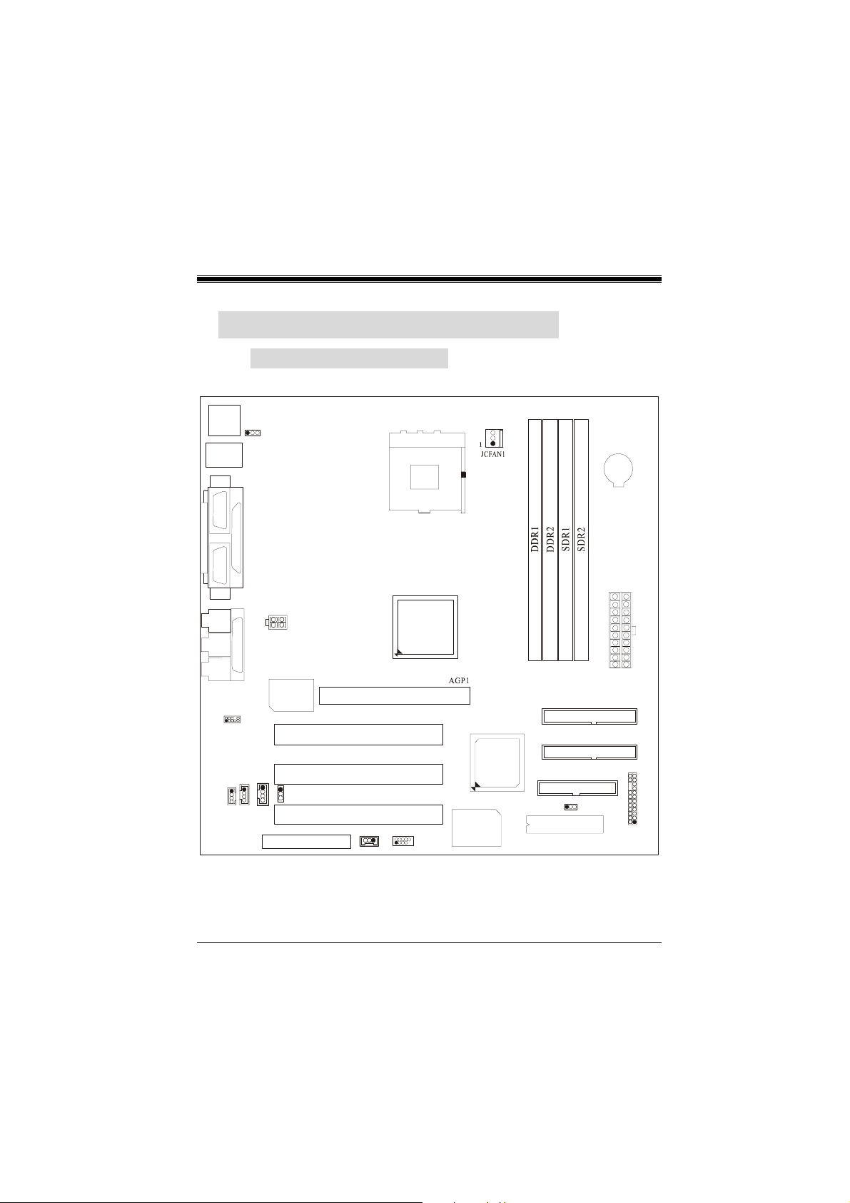
2. Mainboard Configuration
2-1. Layout of U8668
JKBMS1
K/B
&
Mouse
JLAN
USB & LAN
JCOM1
COM1
VGA1
JVGA1
SPKR-OUT
LINE-IN
MIC-IN
JAUDIO1
2
1
JCDIN2
1
Parallel Port
JPRNT1
GAME Port
10
9
1
JCDIN1
JKBV1
JATXPWR2
U16
Realtek
RTL 81 00B
JTAD1
11
1
JCODECSEL
CNR SLOT
PCI SLOT
PCI SLOT
PCI SLOT
CNR1
AGP SLOT
JWOL1
Socket 478
JUSB3
2
1
1
CPU
VT8751
PCI1
PCI2
PCI3
10
9
CPU1
U13
VT8233A
Winbond
W83697HF
PRIMARY IDE CONN.
U19
SECONDARY IDE CONN.
FLOPPY DISK CONN.
1
BIOS
JATXPWR1
JCMOS1
BAT1
JPANEL1
2324
12
1-7

Chapter 1 Motherboard Description
2-2. Component Index
1-8
 Loading...