

Page 1
TP67B+ Setup Manual
FCC Information and Copyright
This equipment has been tested and found to comply with the limits of a Class
B digital device, pursuant to Part 15 of the FCC Rules. These limits are designed
to provide reasonable protection against harmful interference in a residential
installation. This equipment generates, uses, and can radiate radio frequency
energy and, if not installed and used in accordance with t he instructions, may
cause harmful interference to radio communications. There is no guarantee
that interference will not occur in a particular installation.
The vendor makes no representations or warranties with respect to the
contents here and specially disclaims any implied warranties of merchantability
or fitness for any purpose. Further the vendor reserves the right to revise this
publication and to make changes to the contents here without obligation to
notify any party beforehand.
Duplication of this publication, in part or in whole, is not allowed without first
obtaining the vendor’s approval in writing.
The content of this user’s manual is subject to be changed without notice and
we will not be responsible for any mistakes found in this user’s manual. All the
brand and product names are trademarks of their respective companies.
Dichiar azione di confor mità
sintetica
Ai sensi dell’art. 2 comma 3 del D.M.
275 del 30/10/2002
Si dichiara che questo prodotto è
conforme alle normative vigenti e
soddisfa i requisiti essenziali richiesti
dalle direttive
2004/108/CE, 2006/95/CE e
1999/05/CE
quando ad esso applicabili
Short De cla rat ion of conf ormity
We declare this product is complying
with the laws in force and meeting all
the essential requirements as specified
by the directives
2004/108/CE, 2006/95/CE and
1999/05/CE
whenever these laws may be applied
Page 2

Table of Contents
Chapter 1: Introduction ........................................ 1
1.1 Before You Start......................................................................................... 1
1.2 Package Checklist..................................................................................... 1
1.3 Motherboard Features.............................................................................. 2
1.4 Rear Panel Connectors.............................................................................. 3
1.5 Motherboard Layout................................................................................. 4
Chapter 2: Hardware Installation .......................... 5
2.1 Installing Central Processing Unit (CPU) ............................................... 5
2.2 FAN Headers.............................................................................................. 7
2.3 Installing System Memory ........................................................................ 8
2.4 Connectors and Slots................................................................................ 10
Chapter 3: Headers & Jumpers Setup .................. 14
3.1 How to Setup Jumpers............................................................................. 14
3.2 Detail Settings .......................................................................................... 14
Chapter 4: RAID Functions .................................. 19
4.1 Operating System.................................................................................... 19
4.2 Raid Arrays............................................................................................... 19
4.3 How RAID Works ..................................................................................... 19
Chapter 5: T-Series BIOS & Software................... 23
5.1 T-Series UEFI BIOS ................................................................................... 23
5.2 T-Series Software...................................................................................... 26
Chapter 6: Useful Help ........................................ 36
6.1 Driver Installation Note.......................................................................... 36
6.2 Extra Information.................................................................................... 37
6.3 Troubleshooting....................................................................................... 38
Appendix: SPEC In Other Languages ................... 39
German.................................................................................................................. 40
French .................................................................................................................... 42
Italian..................................................................................................................... 44
Spanish ................................................................................................................... 46
Portugue se ............................................................................................................ 48
Polish...................................................................................................................... 50
Russian ................................................................................................................... 52
Arabic..................................................................................................................... 54
Japanese ................................................................................................................ 56
Page 3
CHAPTER 1: INTRODUCTION
TP67B+
1.1 B
EFORE YOU START
Thank you for choosing our product. Before you start installing the
motherboard, please make sure you follow the instructions below:
Prepare a dry and stable working environment with
sufficient lighting.
Always disconnect the computer from power outlet
before operation.
Before you take the motherboard out from anti-static
bag, ground yourself properly by touching any safely
grounded appliance, or use grounded wrist strap to
remove the static charge.
Avoid touching the components on motherboard or the
rear side of the board unless necessary. Hold the board
on the edge, do not try to bend or flex the board.
Do not leave any unfastened small parts inside the
case after installation. Loose parts will cause short
circuits which may damage the equipment.
Keep the computer from dangerous area, such as heat
source, humid air and water.
The operating temperatures of the computer should be
0 to 45 degrees Celsius.
1.2 PACKAGE CHECKLIST
Serial ATA Cable X 3
Rear I/O Panel for ATX Case X 1
User’s Manual X 1
Fully Setup Driver CD X 1
USB 2.0 Cable X1 (optional)
Serial ATA Power Cable X 1 (optional)
Note: The package contents may be different due to area or your motherboard version.
1
Page 4

Motherboard Manual
1.3 MOTHERBOARD FEATURES
Socket 1155
CPU
Chipset
Super I/O
Main
Memory
SATA 2 & 3
LAN
Sound
Codec
USB3.0
Slots
On Board
Connectors
Int e l Core i7 / i5 / i3 / Pent iu m / Ce le ron
processor
Intel P67
IT8728
Prov ides the most common ly used legac y
Super I/O functionality.
Low Pin Count Interface
DDR3 DIMM Slots x 4
Max Memory Capacity 16GB
Each DIMM supports 512MB/
1GB/2GB/4GB DDR3
Integrated Serial ATA Controller
Realtek RTL 8111E
ALC892
NEC uPD720200 Data transfer rates up to 600 MB/s
PCI slot x2 Supports PCI expansion cards
PCI-E Gen2 x16 @ x16 s lot x1 Supports PCI-E Gen2 x16 expansion card
PCI-E Gen2 x16 @ x4 slot x1 Supports PCI-E Gen2 x4 expansion card
PCI-E Gen2 x1 slot x1 Supports PCI-E Gen2 x1 expansion card
SATA3 Connector x2 Each co nnector s upports 1 SATA3 devices
SATA2 Connector x4 Each co nnector s upports 1 SATA2 devices
Front Panel Connector x1 Supports front panel facilities
Front Audio Connector x1 Supports front panel audio function
CPU Fan Header x1 CPU Fan power supply (with Smart Fan function)
System Fan Header x2 System Fan Power supply
SPEC
Supports Execute D isab le Bit / Enh anced Intel
SpeedSt ep® / Inte l Ar ch ite cture-64 / Ex tended
Memory 64 Technology / V irtualization Technology /
Hyp er T hr eading
En v iron ment Co n tro l in it iat ives ,
Hardware Monitor Controller
Fan Sp eed Contro ller
ITE's "S mart Guard ian" funct ion
Dual Channel Mode DDR3 memory modu le
Supports DDR3 1066 / 1333
Supports DDR3 1600 (OC) / 1866 (OC) / 2133 (OC)
Register ed DIMM and ECC D IMM is not supported
Data transfer rates up to 3.0 Gb/s / 6.0 Gb/s.
SATA Version 2.0 / 3.0 specification compliant
10 / 100 Mb/s / 1Gb/s auto negot iation
Half / Full duplex capability
5.1 channels audio out
High Definition Audio
2
Page 5
Back Panel
I/O
Board Size
OS Support
TP67B+
SPEC
Clear CMOS Head er x1 Restore CMOS dat a to facto ry default
USB2.0 Co nnector x2 Each conne ctor s upports 2 fro nt panel USB2.0 ports
Consumer IR Connector x1 Supports infrared funct ion
Serial Port Connector x1 Connects to RS-232 Port
S/PDIF out Connector x1 Supports digital audio out function
Power Connector (24pin) x1 Connects to Power supply
Power Connector (8pin) x1 Connects to Power supply
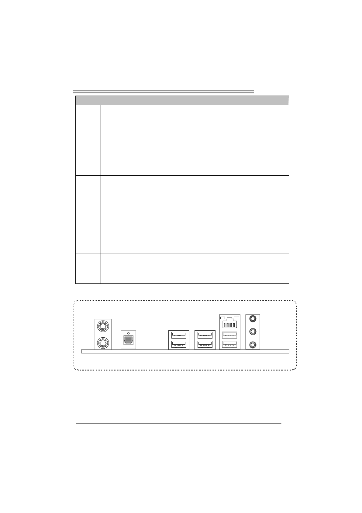
PS/2 Keybo ard x1
PS/2 Mous e x1
S/PDIF Out x1
LAN port x1
USB2.0 Port x4
USB3.0 Port x2
Audio Jack x3
305 (W) x 220 (L) mm ATX
Windows XP / Vista / 7
Connects to PS/2 Keyboard
Connects to PS/2 Mouse
Provides digital audio out function
Connect to RJ-45 et hernet cable
Connect to USB2.0 devices
Connect to USB3.0 devices (by NEC uPD720200)
and USB2.0/USB1.X devices (by P67)
Provide Audio-In/Out and Mic. connect ion
Biostar reserves the r ight to add or remove support
for any OS with or without notice
1.4 REAR PANEL CONNECTORS
PS/2
Mouse
USB3.0X2
PS/2
Keyboard
S/PDIF
Out
USB2.0X2
NOTE: USB3.0 ports are backward compatible with USB2.0/USB1.X devices. USB3.0 is
controlled by NEC uPD720200, but, USB2.0/USB1.X is controlled b y P67.
LAN
Line In/
Surround
Line Out
Mic In 1/
Bass/ Center
USB2.0X2
3
Page 6
Motherboard Manual
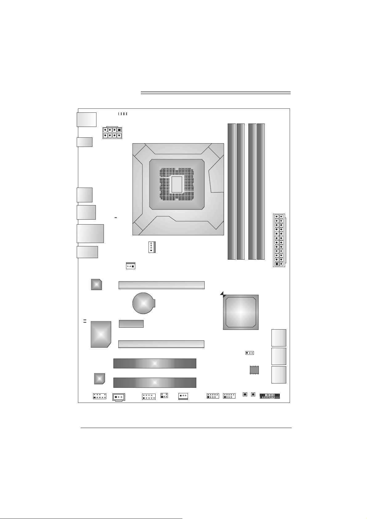
1.5 MOTHERBOARD LAYOUT
PH4
PH2
PH3
KBMS1
PH1
SPDIF1
USB1
USB3_0
RJ4 5USB1
AUD IO1
LED_D1
LED _ D2
ATXPW R2
LAN
Super
I/O
VTT _LED1
SYS_FAN1
PEX1_1
Socket 1155
CPU_FAN1
PEX16_1
BAT1
PEX16_2
CPU1
DDR 3_ A1
DDR 3_ A2
Intel
P67
DB2DR3_
DDR 3_ B1
ATXPW R1
SATA1
4
CODEC
JSPDIFOUT1
F_AUDIO1
Note: represents the 1■
PCI1
PCI2
J_CO M1
CIR1
SYS_FAN2
st
pin.
PA N EL 1
SATA 2
SATA 3
JCMOS1
BIOS
SW_RST1
F_USB1F_U SB2
SW_PW R1
Page 7
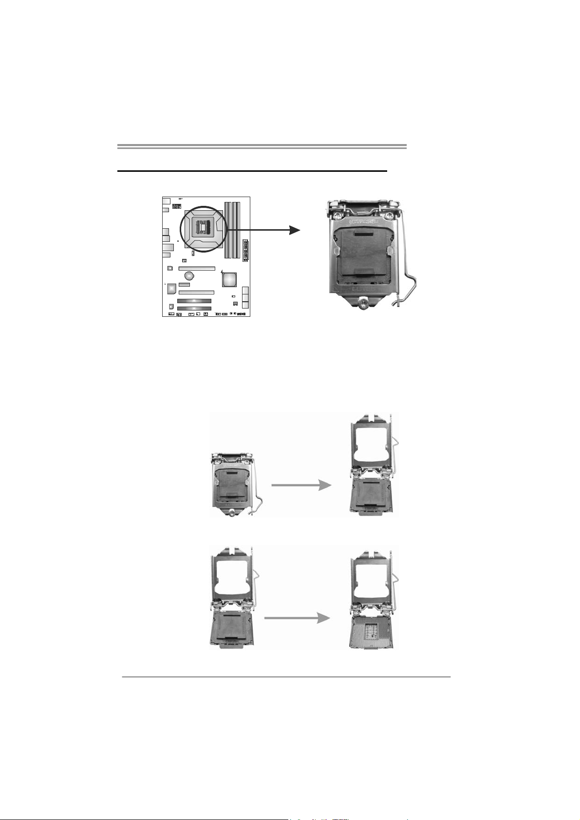
CHAPTER 2: HARDWARE INSTALLATION
TP67B+
2.1 I
NSTALLING CENTRAL PROCESSING UNIT (CPU)
Special Notice:
Remove Pin Cap before installation, and make good preservation
for future use. When the CPU is removed, cover the Pin Cap on the
empty socket to ensure pin legs won’t be damaged.
Step 1: Pull the socket locking lever out from the socket and then raise
the lever up.
Step 2: Remove the Pin Cap.
5
Page 8
Motherboard Manual
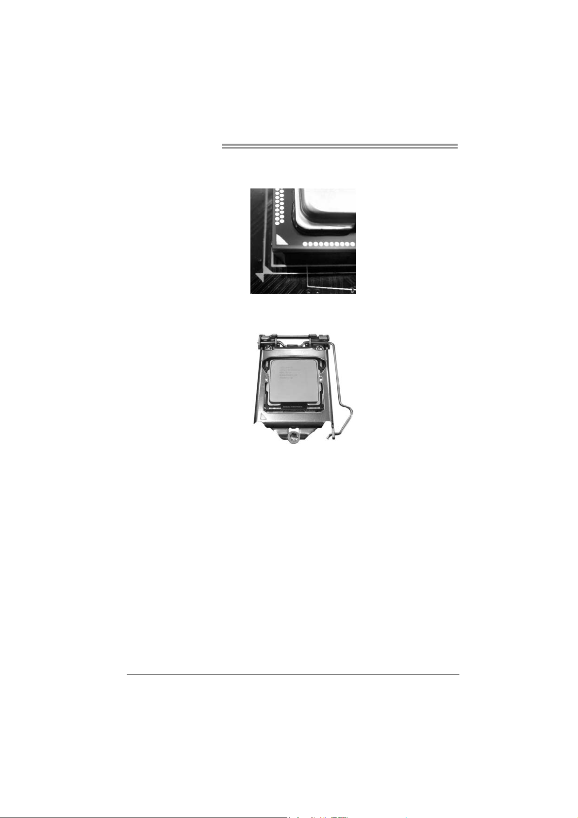
Step 3: Look for the triangular cut edge on socket, and the golden dot on
CPU should point forwards this triangular cut edge. The CPU will
fit only in the correct orientation.
Step 4: Hold the CPU down firmly, and then lower the lever to locked
position to complete the installation.
Step 5: Put the CPU Fan and heatsink assembly on the CPU and buckle it
on the retention frame. Connect the CPU FAN power cable into
the CPU_FAN1 to complete the installation.
6
Page 9
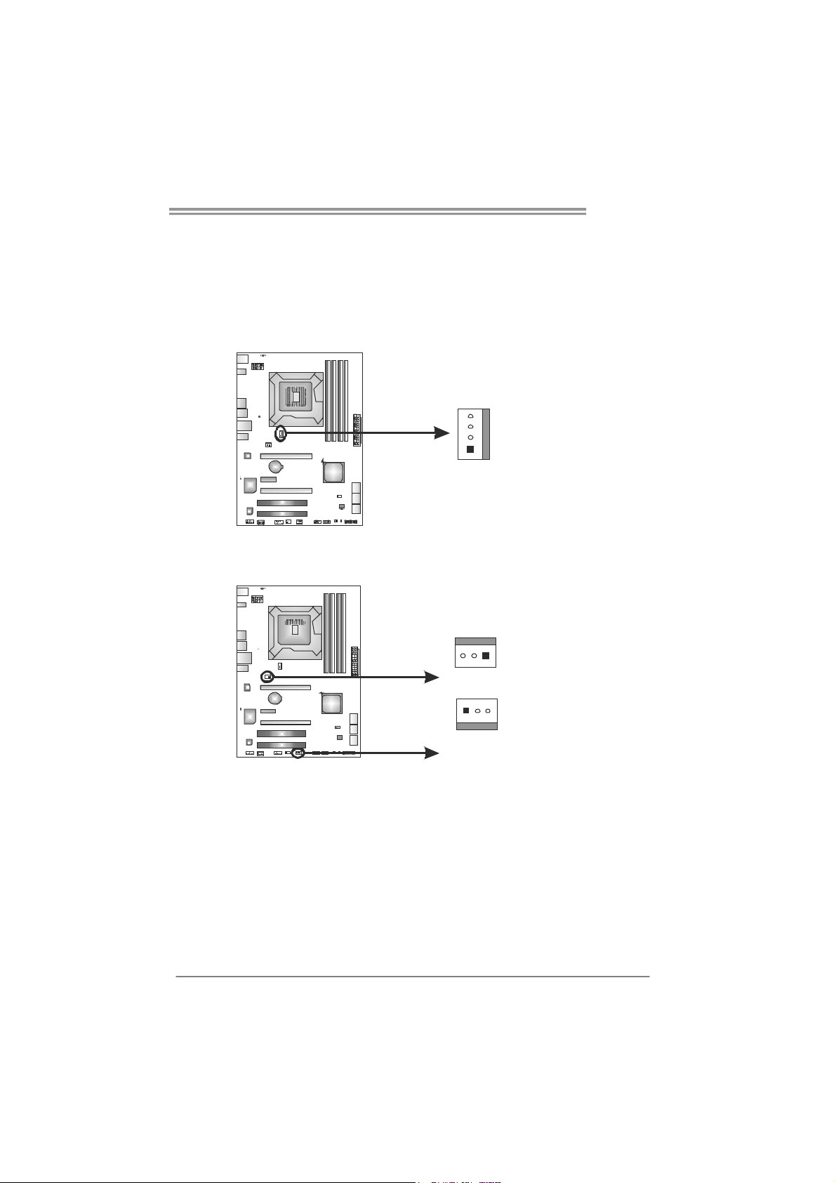
2.2 FAN HEADERS
These fan headers support cooling-fans built in the computer. The fan
cable and connector may be different according to the fan manufacturer.
Connect the fan cable to the connector while matching the black wire to
pin#1.
CPU_FAN1: CPU Fan Header
Pin
Assignment
1 Ground
4
1
SYS_FAN1/SYS_FAN2: System Fan Headers
SYS_FAN1
13
2 +12V
3
4 Smart Fan
Pin
1 Ground
2 +12V
3 FAN RPM rate
FAN RPM r ate
sense
Control
Assignment
sense
TP67B+
3
1
SYS_FAN2
Note:
The SYS_FAN1/SYS_FAN2 support 3-pin head connectors; the CPU_FAN1 supports
4-pin head connector. When connecting with wires onto connectors, please note that the
red wire is the positive a nd should be connected to pin#2, and the black wire is Ground
and should be co nnected to GND.
7
Page 10
Motherboard Manual
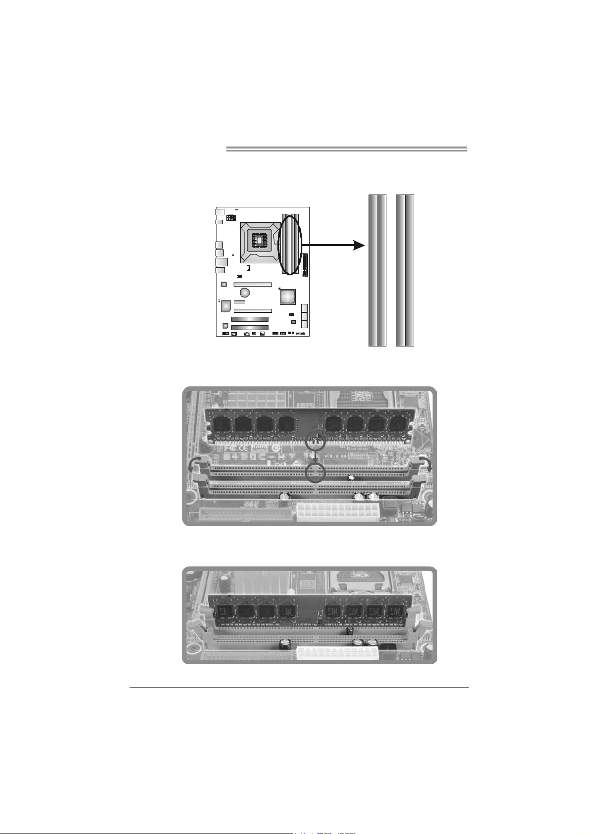
2.3 INSTALLING SYSTEM MEMORY
A. Memory Modules
DDR3_A1
DDR3_B1
DDR3_A2
1. Unlock a DIMM slot by pressing the retaining clips outward. Align a
DIMM on the slot such that the notch on the DIMM matches the
break on the Slot.
DDR3_B2
2. Insert the DIMM vertically and firmly into the slot until the retaining
chip snap back in place and the DIMM is properly seated.
8
Page 11
TP67B+
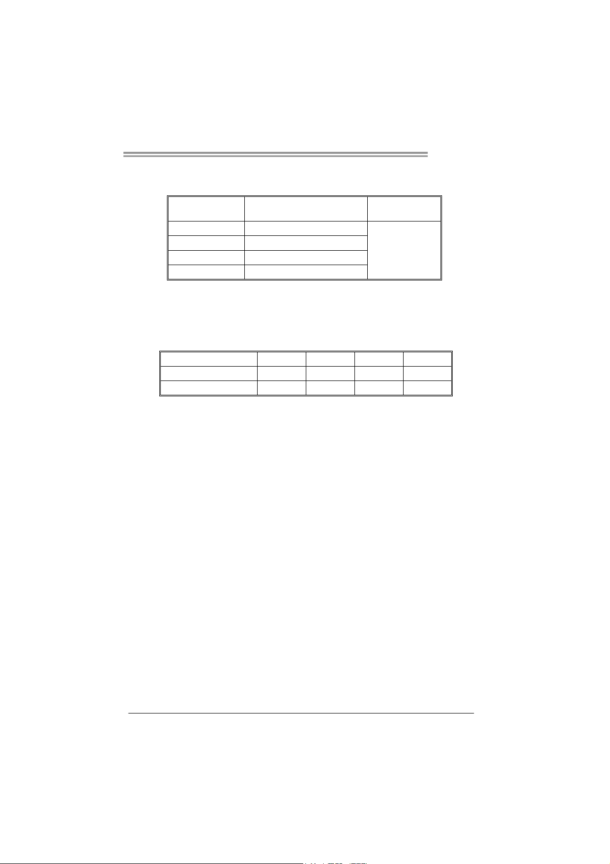
B. Memory Capacity
DIMM Socket
Location
DDR3_A1 512MB/1GB/2GB/4GB
DDR3_A2 512MB/1GB/2GB/4GB
DDR3_B1 512MB/1GB/2GB/4GB
DDR3_B2 512MB/1GB/2GB/4GB
DDR3 Module
Total Mem ory
Size
Max is 16GB.
C. Dual Channel Memory Installation
Please refer to the following requirements to activate Dual Channel function:
Install memory module of the same density in pairs, shown in the table.
Dual Channel Status DDR3_A1 DDR3_A2 DDR3_B1 DDR3_B2
Enabled X O X O
Enabled O O O O
(O means memory installed, X means memory not installed.)
The DRAM bus width of the memory module must be the same (x8 or
x16)
Note:
Memory module must be installed in DDR3-A2 or DDR3-B2 to boot the
system.
9
Page 12

Motherboard Manual
2.4 CONNECTORS AND SLOTS
SATA1: Serial ATA3 Connecto rs
The motherboard has a PCI to SATA Controller with 2 channels SATA3 interface,
it satisfies the SATA 3.0 spec and with transfer rate of 6.0Gb/s.
SATA2/3: Serial ATA2 Connectors
The motherboard has a PCI to SATA Controller with 4 channels SATA2 interface,
it satisfies the SATA 2.0 spec and with transfer rate of 3.0Gb/s.
SATA3 SATA2
Pin
Assignment
1 Ground
2 TX+
3 TX4 Ground
5 RX6 RX+
7 Ground
Assignment
Pin
1 Ground
2 TX+
3 TX4 Ground
5 RX6 RX+
7 Ground
10
Page 13
TP67B+
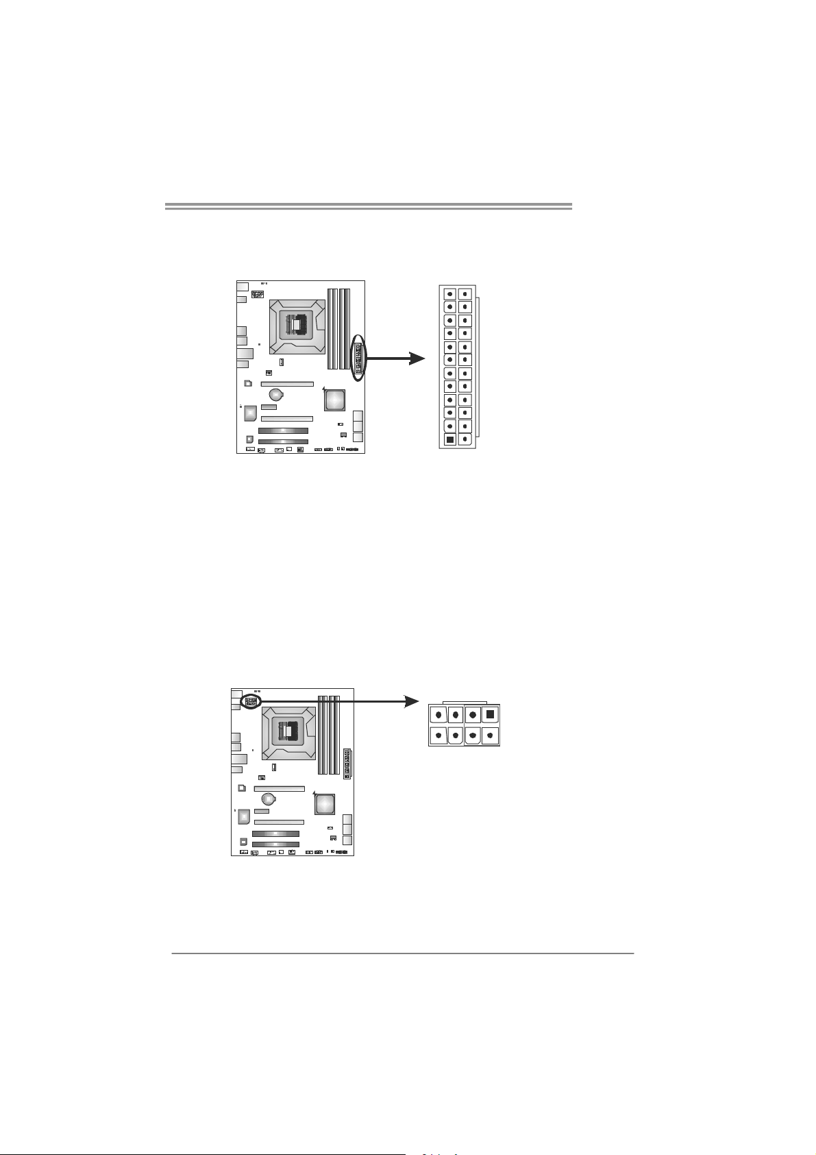
ATXP W R1: ATX Power Source Connector
This connector allows user to connect 24-pin power connector on the ATX
power supply.
12
1
Pin Assignment Pin Assignment
13 +3.3V 1 +3.3V
14 -12V 2 +3.3V
15 Ground 3 Ground
16 PS_ON 4 +5V
17 Ground 5 Ground
18 Ground 6 +5V
19 Ground 7 Ground
20 NC 8 PW_OK
21 +5V 9 Standby Voltage+5V
22 +5V 10 +12V
23 +5V 11 +12V
24 Ground 12 +3.3V
ATXP W R2: ATX Power Source Connectors
These connectors provide +12V to CPU power circuit.
58
24
13
14
Pin
1 +12V
2 +12V
3 Ground
4 Ground
Assignment
Note:
Before you power on the system, please make sure that ATXPWR1& ATXPWR2
connectors have been well plugged-in.
If the CPU power plug is 4-pin, please plug it into Pin 1-2-5-6 of ATXPWR2/3.
11
Page 14
Motherboard Manual
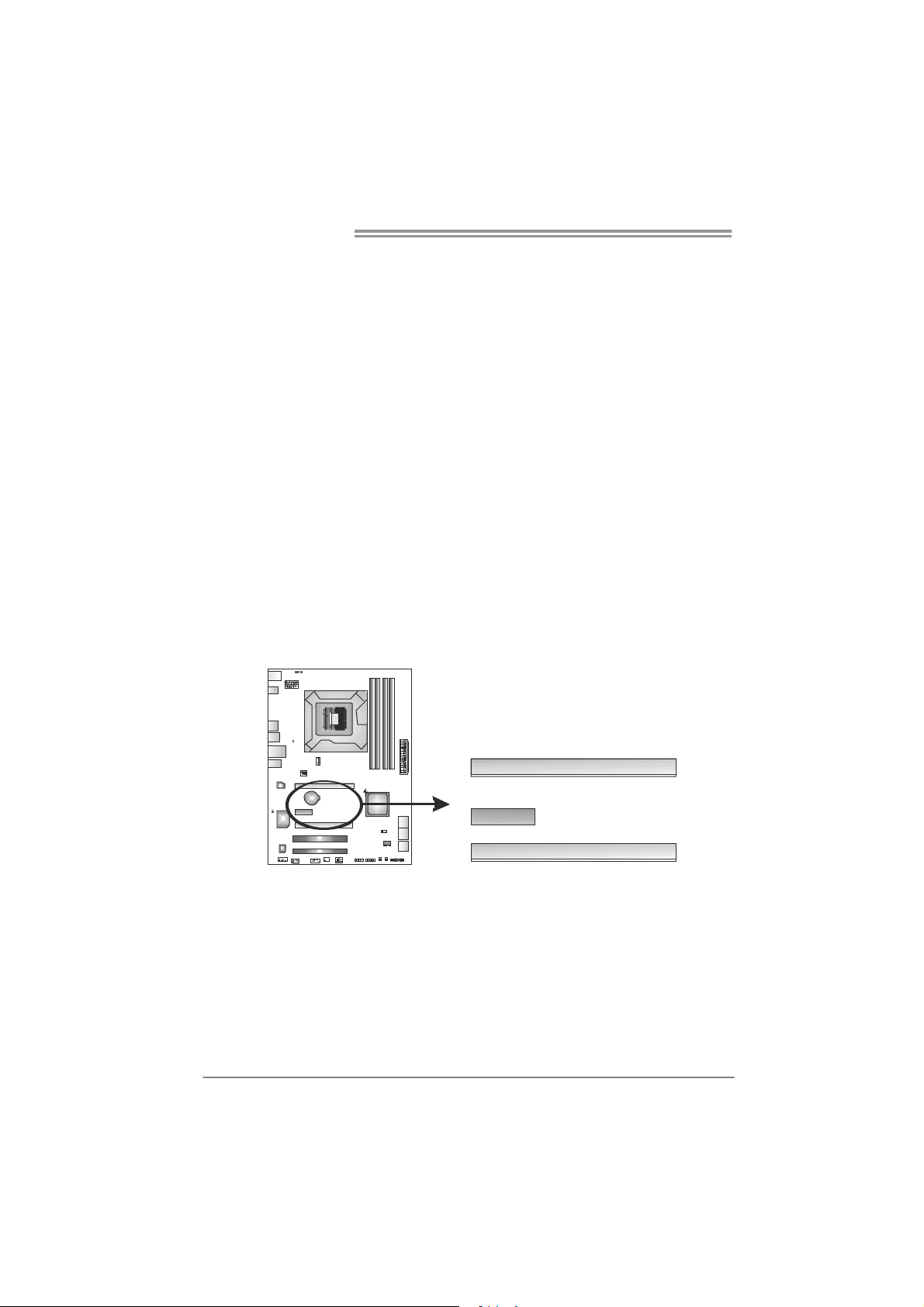
PEX16_1: PCI-Express Gen2 x16 Slot
- PCI-Express 2.0 compliant.
- Maximum theoretical realized bandwidth of 8GB/s simultaneously per
direction, for an aggregate of 16GB/s totally.
- PCI-Express Gen2 supports a raw bit-rate of 5.0Gb/s on the data pins.
- 2X bandwidth over the PCI-Express 1.1 architecture.
PEX16_2: PCI-Express Gen2 x4 Slot
- PCI-Express 2.0 compliant.
- Maximum theoretical realized bandwidth of 2GB/s simultaneously per
direction, for an aggregate of 4GB/s totally.
- 2X bandwidth over the PCI-Express 1.1 architecture.
PEX1_1: PCI-Express Gen2 x1 Slot
- PCI-Express 2.0 compliant.
- Data transfer bandwidth up to 500MB/s per direction; 1GB/s in total.
- PCI-Express supports a raw bit-rate of 2.5Gb/s on the data pins.
- 2X bandwidth over the PCI-Express 1.1 architecture.
12
PEX16_1
PEX1_1
PEX16_2
Page 15
TP67B+
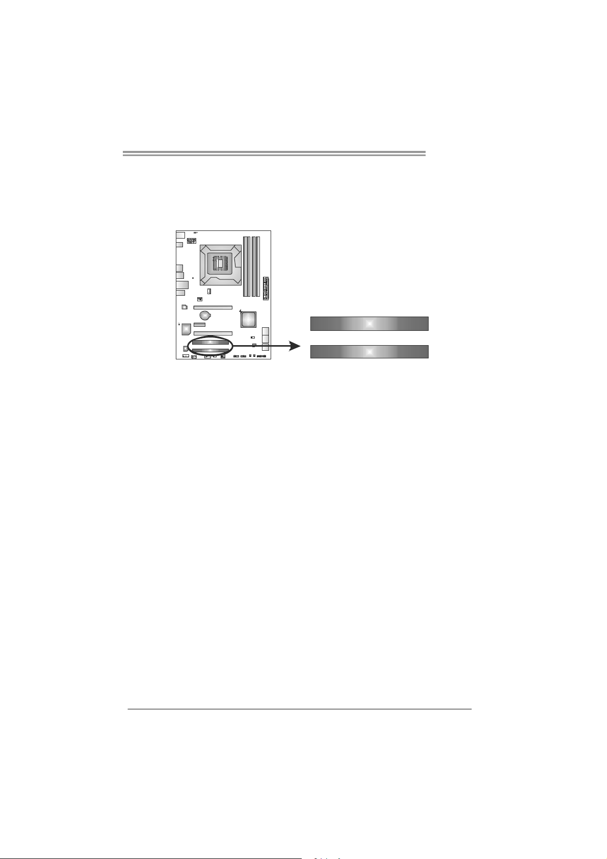
PCI1/PCI2: Peripheral Component Interconnect Slots
This motherboard is equipped with 2 standard PCI slots. PCI stands for
Peripheral Component Interconnect, and it is a bus standard for expansion
cards. This PCI slot is designated as 32 bits.
PCI1
PCI2
13
Page 16
Motherboard Manual
CHAPTER 3: HEADERS & JUMPERS SETUP
3.1 H
OW TO SETUP JUMPERS
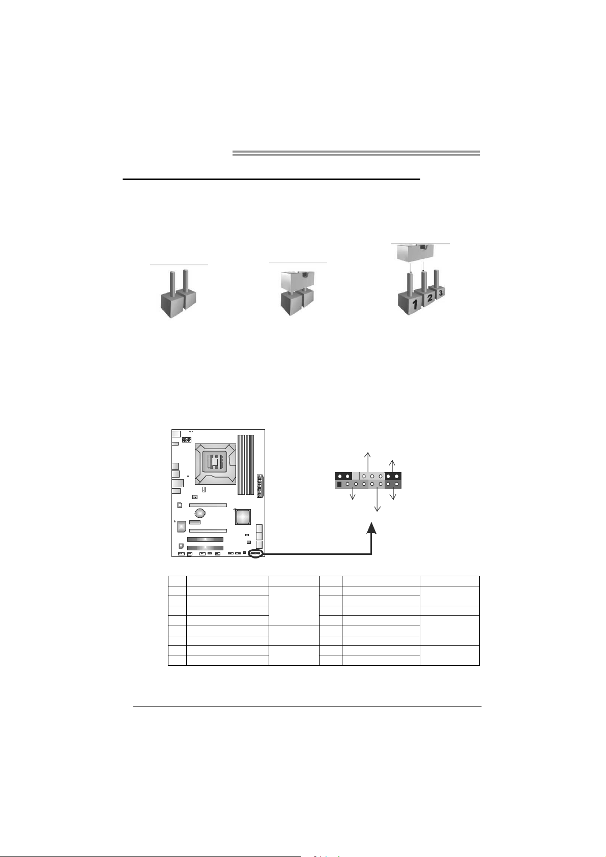
The illustration shows how to set up jumpers. When the jumper cap is
placed on pins, the jumper is “close”, if not, that means the jumper is
“open”.
Pin opened Pin closed Pin1-2 closed
3.2 DETAIL SETTINGS
PANEL1: Front Panel Header
This 16-pin connector includes Power-on, Reset, HDD LED, Power LED, and
speaker connection. It allows user to connect the PC case’s front panel switch
functions.
9
1
POW _LED
SPK
++
HLED
+
On/Off
-
-
RST
16
8
14
Pin Assignment Function Pin Assignment Function
1 +5V 9 N/A
2 N/A 10 N/A
3 N/ A 11 N/ A N/ A
4 Speaker
5 HDD LED (+) 13 Power LED (+)
6 HDD LED (-)
7 Ground 15 Power button
8 Reset control
Speaker
Connector
Hard drive
LED
Reset button
12 Power LED (+)
14 Power LED (-)
16 Ground
N/A
Power LED
Power-on button
Page 17
TP67B+
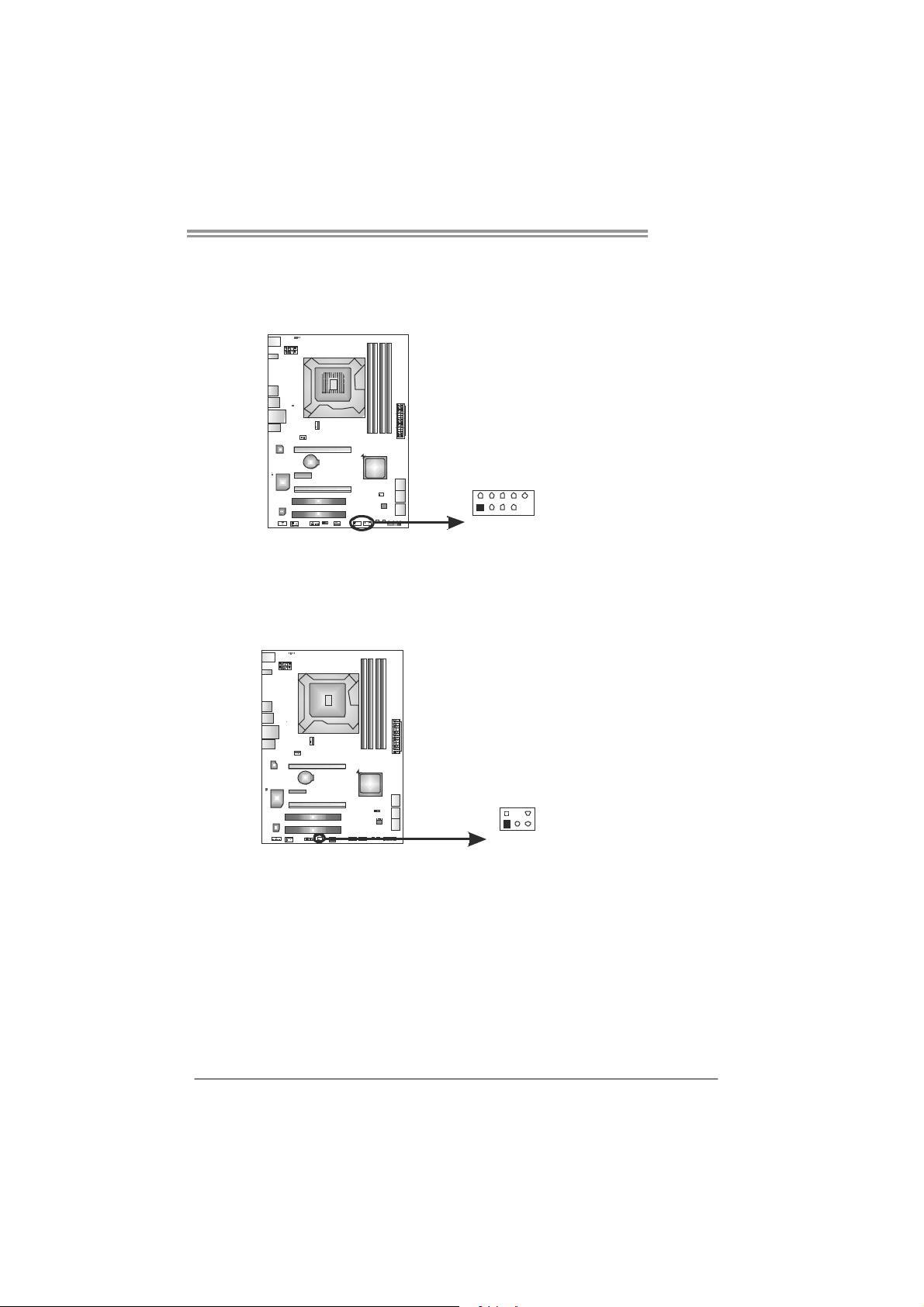
F_USB1/F_USB2: Headers for USB 2.0 Ports at Front Panel
These headers allow user to connect additional USB cable on the PC front panel,
and also can be connected with internal USB devices, like USB card reader.
Assignment
Pin
1 +5V (fused)
2 +5V (fused)
3 USB4 USB5 USB+
6 USB+
F_ USB1USB2 F_
2
10
7 Ground
8 Ground
9 Key
10 NC
CIR1: Consumer IR Connector
This header is for infrared remote control and communication.
1
125
9
6
Pin Assignment
1 IrDA serial input
2 Ground
3 Ground
4 Key
5 IrDA serial output
6 IR Power
15
Page 18
Motherboard Manual
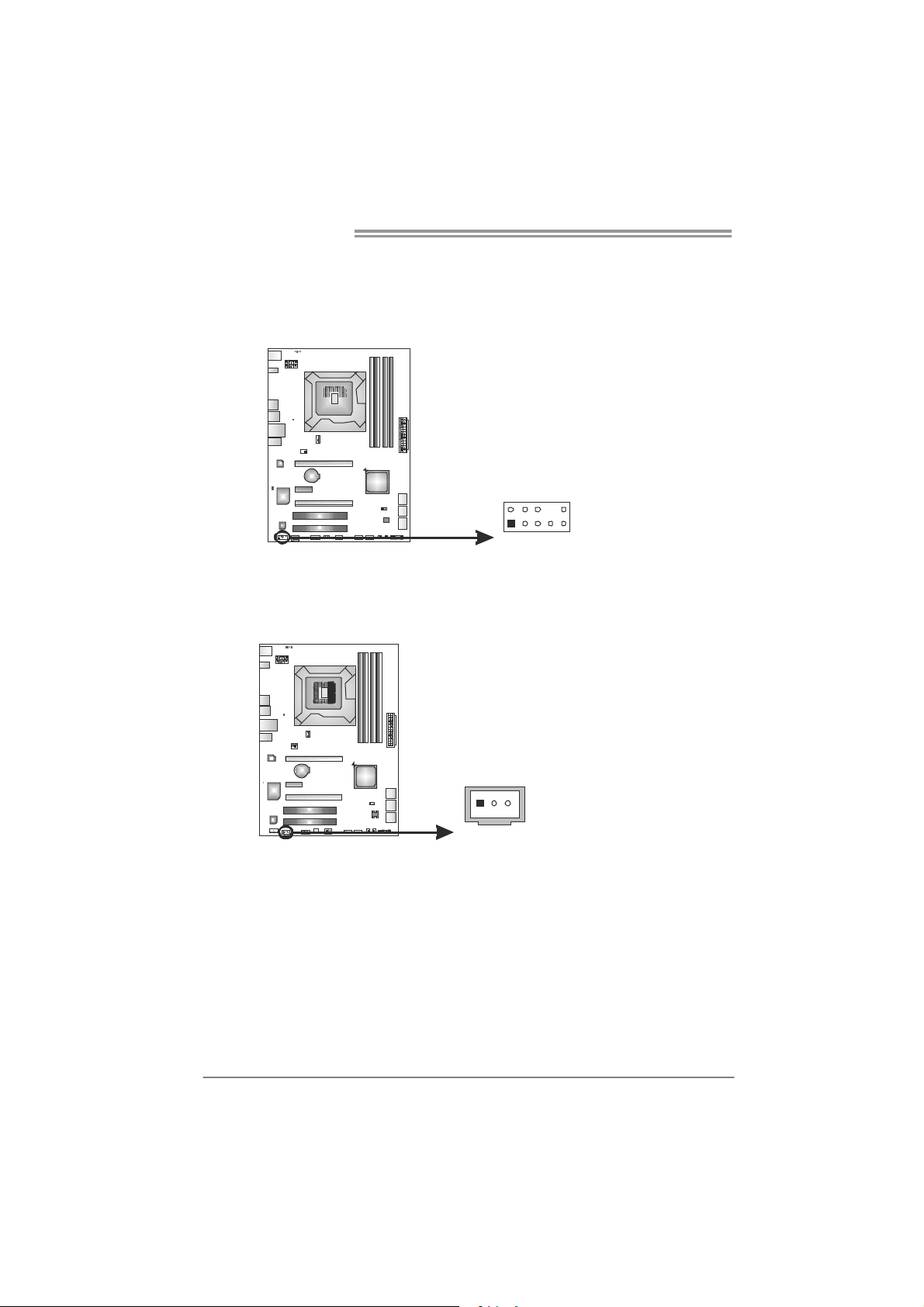
F_AUDIO1: Front Panel Audio Header
This header allows user to connect the front audio output cable with the PC front
panel. This header allows only HD audio front panel connector; AC’97 connector
is not acceptable.
Pin Assignment
1 Mic Left in
2 Ground
3 Mic Right in
4 GPIO
5 Right line in
6 Jack Sense
7 Front Sense
8 Key
2
10
9 Left line in
10 Jack Sense
1
9
JSPDIFOUT1: Digital Audio-out Connector
This connector allows user to connect the PCI bracket SPDIF output header.
Pin
Assignment
1 +5V
2 SPDIF_OUT
3 Ground
31
16
Page 19
TP67B+
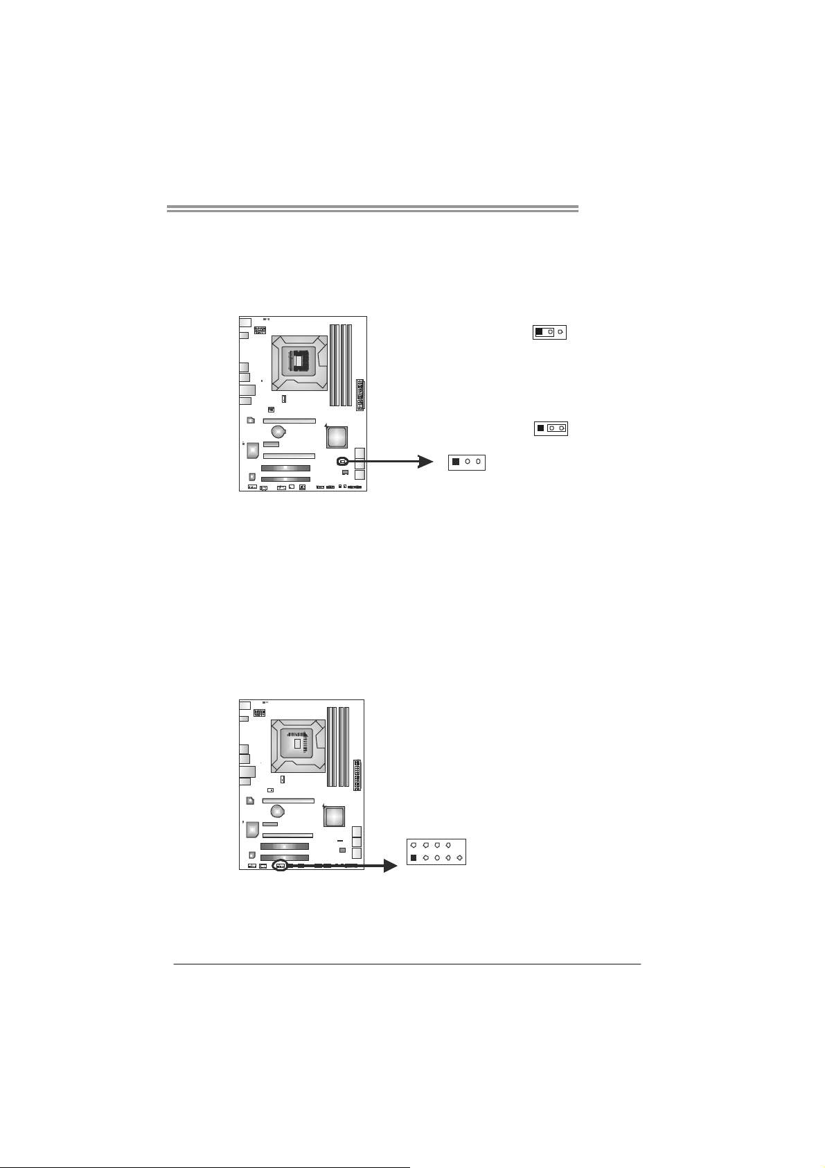
JCMOS1: Clear CMOS Header
Placing the jumper on pin2-3 allows user to restore the BIOS safe setting and
the CMOS data. Please carefully follow the procedures to avoid damaging the
motherboard.
13
Pin 1-2 Close:
Normal Operation (default).
Pin 2-3 Close:
Clear CMOS data.
13
13
※ Clear CMOS Procedures:
1. Remove AC power line.
2. Set the jumper to “Pin 2-3 close” .
3. Wait for five seconds.
4. Set the jumper to “Pin 1-2 close” .
5. Power on the AC.
6. Reset your desired password or clear the CMOS data.
J_COM1: Serial Port Connector
The motherboard has a Serial Port Connector for connecting RS-232 Port.
Pin
Assignment
1 Carrier detect
2 Received data
3 Transmitted data
4 Data terminal ready
5 Signal ground
6 Data set ready
210
19
7 Request to send
8 Clear to send
9 Ring indicator
10 NC
17
Page 20
Motherboard Manual
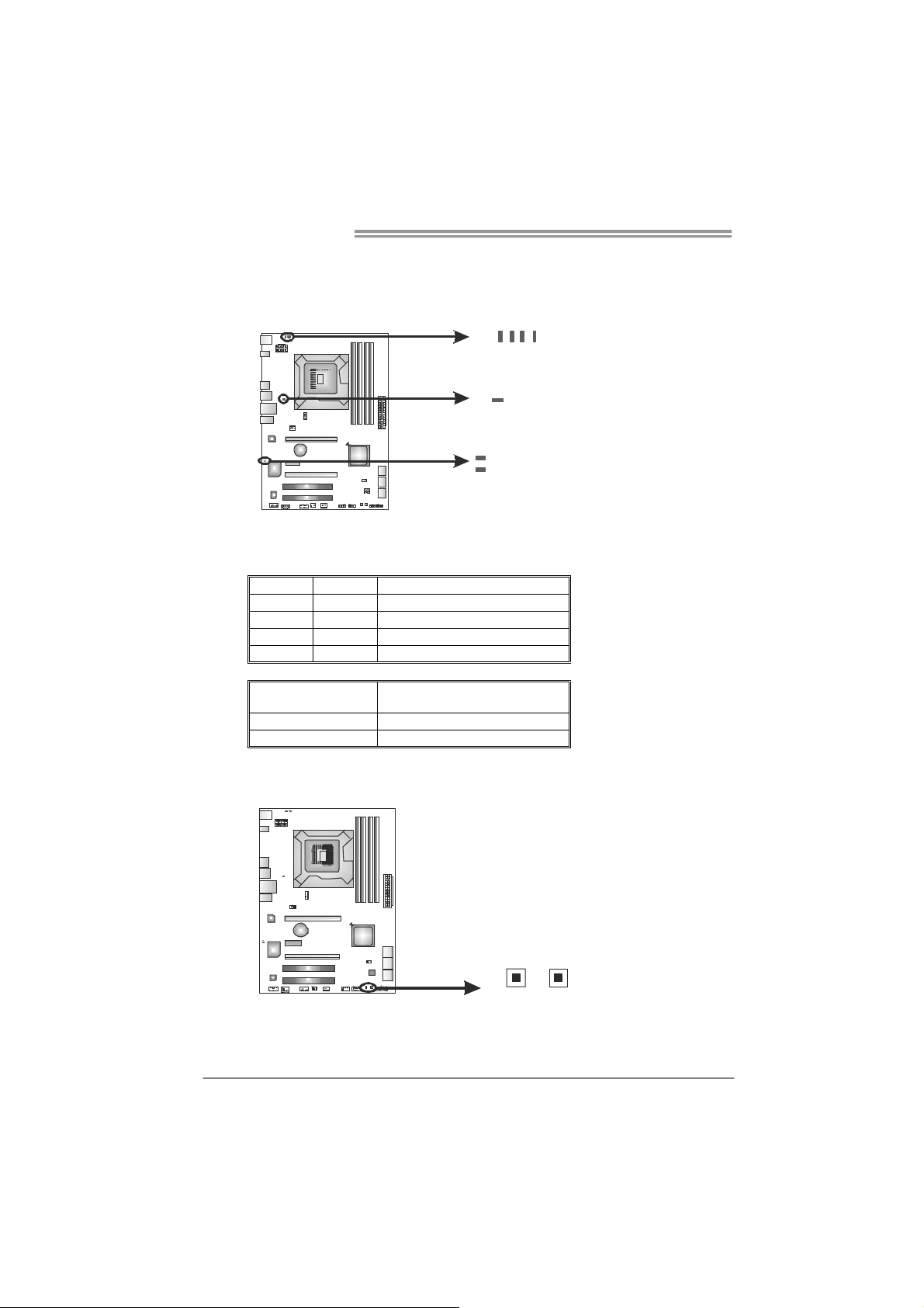
On-Board LED Indicators
There are 7 LED indicators on the motherboard showing system status.
LED_D1 & LED_D2: Debug Indicators
PH1 ~ PH4 / VTT_LED1: Power Status Indicators
Please refer to the tables below for specific messages:
LED_D1 LED_D2 Message
ON ON Norma l
ON OFF Memory Error
OFF ON VGA Error
OFF OFF Abnormal: CPU / Chipset error.
PH1 ~ PH4
VTT_LED1
ON Phase Active
OFF Phase Inactive
On-Board Buttons
There are 2 on-board buttons.
Phase Indicator
PH3
PH4
PH2
VTT_LED1
LED_D1
LED_D2
PH1
18
SW_RST1: Reset button.
SW_PWR1: Power Switch button.
SW_PWR1
SW_RST 1
Page 21
CHAPTER 4: RAID FUNCTIONS
TP67B+
4.1 O
Supports Windows Vista and Windows 7.
PERATING SYSTEM
4.2 RAID ARRAYS
RAID supports the following types of RAID arrays:
RAID 0: RAID 0 defines a disk striping scheme that improves disk read and write times for
many applications.
RAID 1: RAID 1 defines techniques for mirroring data.
RAID 10: RAID 10 combines the techniques used in RAID 0 and RAID 1.
RAID 5: RAID 5 provides fault to lerance and better utilization of disk capacity.
4.3 HOW RAID WORKS
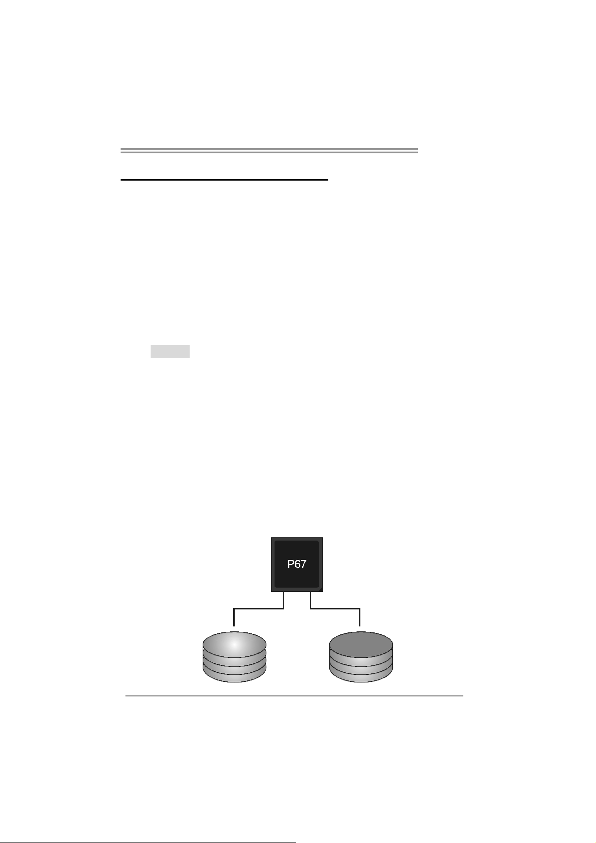
RAID 0:
The controller “stripes” data across multiple drives in a RAID 0 array system. It breaks
up a large f ile into smaller blocks and performs disk rea ds an d writ es a cro ss m ultip le
drives in parallel. The size of each block is determined by the stripe size parameter,
which you set during the creation of the RAID set based on the system environment. This
technique reduces overall disk access time and offers high bandwidth.
Features and Benefits
Drives: Minimum 2, and maximum is up to 6 or 8. Depending on the
platform.
Uses: Intended for non-critical data requiring high data throughput, or any
environment that does not require fault tolerance.
Benefits: provides increased data throughput, especially for large files. No
capacity loss penalty for parity.
Drawbacks: Does not deliver any fault tolerance. If any drive in the array
fails, all data is lost.
Fault Tolerance: No.
Block 1
Blo ck 3
Blo ck 5
Block 2
Blo ck 4
Blo ck 6
19
Page 22
Motherboard Manual
RAID 1:
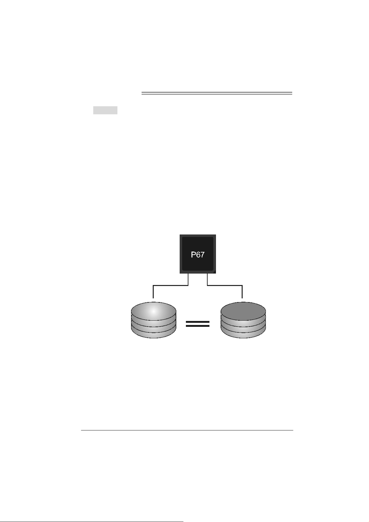
Every read and write is actually carried out in parallel across 2 disk drives in a RAID 1
array system. The mirrored (backup) copy of the data can reside on the same disk or on a
second redundant drive in the array. RAID 1 provides a hot-standby copy of data if the
active volume or drive is corrupted or becomes unavailable because of a hardware failure.
RAID techniques can be applied for high-availability solutions, or as a form of automatic
backup that eliminates tedious manual backups to more expensive and less reliab le
media.
Features and Benefits
Drives: Minimum 2, and maximum is 2.
Uses: RAID 1 is ideal for small databases or any other application that
requires fault tolerance and minimal capacity.
Benefits: Provides 100% data redundancy. Should one drive fail, the
controller switches to the other drive.
Drawbacks: Requires 2 drives for the storage space of one drive.
Performance is impaired during drive rebuilds.
Fault Tolerance: Ye s .
20
Block 1
Block 2
Block 3
Block 1
Block 2
Block 3
Page 23
TP67B+
RAID 10:
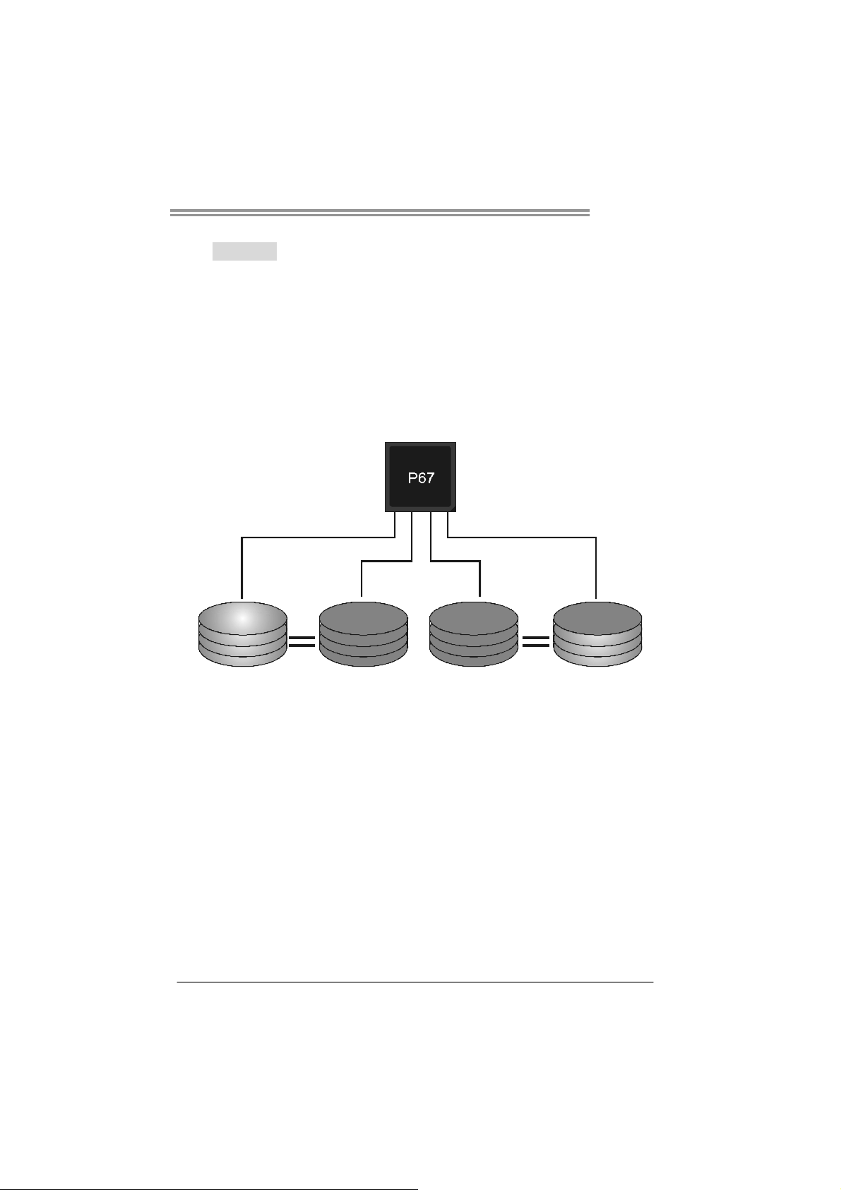
RAID 1 drives can be stripped using RAID 0 techniques. Resulting in a RAID 10
solution for improved resiliency, performance and rebuild performance.
Features and Benefits
Drives: Minimum 4, and maximum is 6 or 8, depending on the platform.
Benefits: Optimizes for both fault tolerance and performance, allowing for
automatic redundancy. May be simultaneously used with other RAID levels
in an array, and allows for spare disks.
Drawbacks: Requires twice the available disk space for data redundancy,
the same as RAID level 1.
Fault Tolerance: Ye s .
Block 1
Block 3
Block 5
Block 1
Block 3
Block 5
Block 2
Block 4
Block 6
Block 2
Block 4
Block 6
21
Page 24
Motherboard Manual
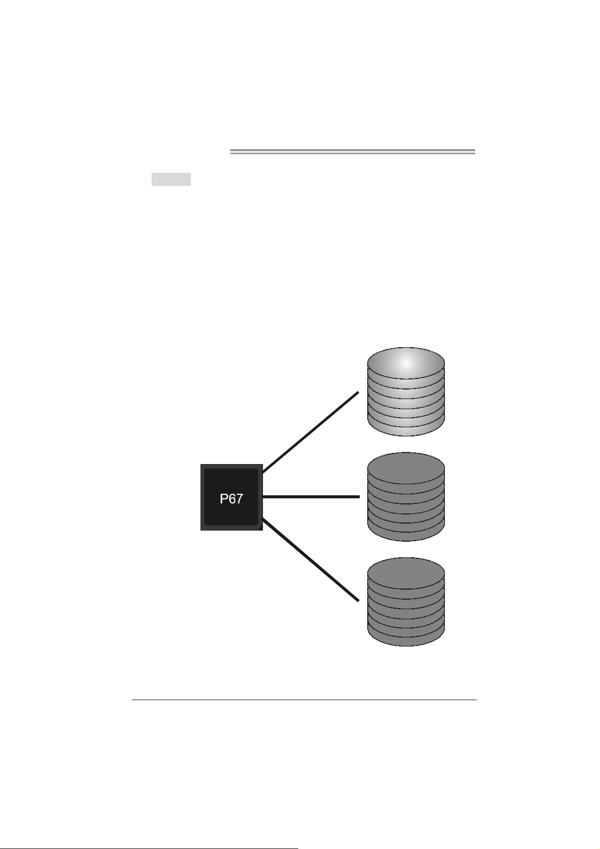
RAID 5:
RAID 5 stripes both data and parity information across three or more drives. It writes
data and parity blocks across all the drives in the array. Fault tolerance is maintained by
ensuring that the parity information for any given block of data is placed on a different
drive from those used to store the data itself.
Features and Benefits
Drives: Mi nimu m 3.
Uses: RAID 5 is recommended for transaction processing and general
purpose service.
Benefits: An ideal combination of good performance, good fault tolerance,
and high capacity and storage efficiency.
Drawbacks: Individual block data transfer rate same as a single disk. Write
performance can be CPU intensive.
Fault Tolerance: Yes.
Disk 1
DATA 1
DATA 3
PA RI T Y
DATA 7
DATA 9
PA RI T Y
22
Disk 2
DATA 2
PA RI T Y
DATA 5
DATA 8
PA RI T Y
DATA 11
Disk 3
PA RI T Y
DATA 4
DATA 6
PA RI T Y
DATA 10
DATA 12
Page 25

CHAPTER 5: T-SERIES BIOS & SOFTWARE
Y
p
TP67B+
5.1 T-S
ERIES UEFI BIOS
T-Series UEFI BIOS Features
Overclocking Navigator Engine (O.N.E.)
Self Recovery System (S.R.S)
Smart Fan Function
BIO-Flasher: Update UEFI BIOS file from USB Flash Drive
!! WARNING !!
For better system performance, the UEFI BIOS firmware is being
continuously updated. The UEFI BIOS information described below
in this manual is for your reference only and the actual UEFI BIOS
information and settings on board may be different from this
manual. For further information of setting up the UEFI BIOS,
lease refer to the UEFI BIOS Manual in the Setup CD.
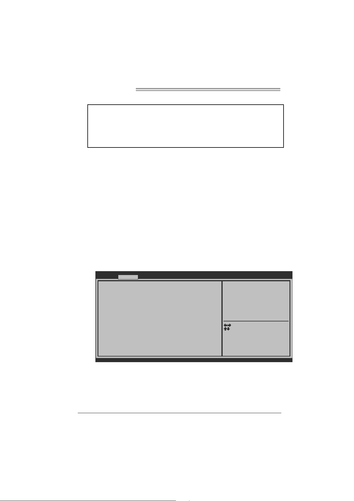
A. Overclocking Navigator Engine (O.N.E.)
O.N.E provides 4 systems allowing users to customize personal overclock
settings: Manual CPU System, Manual Memory System, Manual PWM
System, and Manual Voltage System.
Main Adva nce d Chips et Boot Sec ur ity O.N. E S ave & E xit
Noti ce : Ple ase C le ar CM OS if sy st em no di splay
aft er ov er clock ing
Star t Page [P age - Ma in]
==== Ma nual CPU system == ==
Fixe d CPU R atio [D isabl ed]
CPU Ra tio 28
CPU Ba se Cl ock(1 /100 MH Z) 10 000
CPU Co re Cu rrent Max(Am p) 10 5
Powe r Limit 1 Va lu e (Wa tt) 95
Powe r Limit 2 Sw it ch [E nable d]
Powe r Limit 2 Va lu e 11 8
Enha nc ed In tel S pe edSte p T ech [E nable d]
Turb o Mode [E nable d]
1 Co re Rati o Lim it 31
2 Co re Rati o Lim it 30
3 Co re Rati o Lim it 30
4 Co re Rati o Lim it 29
CPU C1 E [E nable d]
Versi on x.xx .xxxx . C opyri gh t© 20 1x, Ame ric an Me gatre nd s, In c.
Notice:
Not all types of Intel CPU perform above overclock setting ideally; the difference will be based on the
selected CPU model.
BIOS SE TUP U TILI T
You ca n set the ent rance P age
when y ou en ter U EFI BIOS
Setu p
Selec t Scr een
Selec t Ite m
Selec t
Ente r
+/-
Chang e Opt .
F1
Gener al Help
F3
Optim iz ed Defau lts
F4
Save & Res et
ESC
Exit
23
Page 26
Motherboard Manual
Y
NOTE
Overclock is an optional process, but not a “must-do” process; it is not
recommended for inexperienced users. Therefore, we will not be responsible
for any hardware damage which may be caused by overclocking. We also
woul d no t guarantee any overclocking performance.
B. Self Recovery System (S.R.S.)
This function can’t be seen under UEFI BIOS setup, and is always on whenever
the system starts up.
However, it can prevent system hang-up due to inappropriate overclock
actions.
When the system hangs up, S.R.S. will automatically log in the default UEFI
BIOS setting, and all overclock settings will be re-configured.
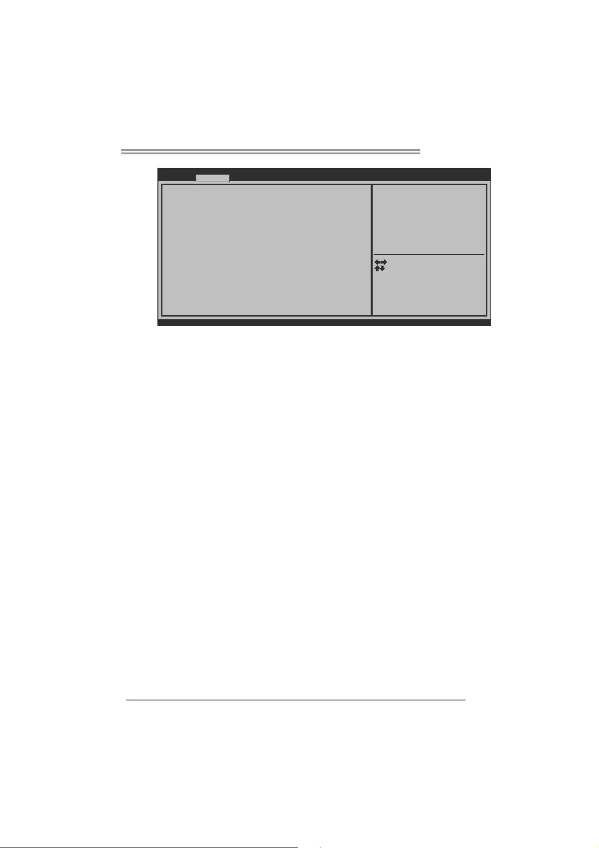
C. Smart Fan Function
Smart Fan Function is under “Smart Fan Control” in “Advanced Menu”.
This is a brilliant feature to control CPU/System Temperature vs. Fan speed.
When enabling Smart Fan function, Fan speed is controlled automatically by
CPU/System temperature.
This function will protect CPU/System from overheat problem and maintain the
system temperature at a safe level.
Main Advanced
> PCI Subsystem Settings
> ACPI Settings/WakeUp Event control
> CPU Configuration
> SATA Configuration
> USB Configuration
> SMART FAN Control
> Super IO Configuration
> H/W Monitor
Chip se t Boo t
BIOS SETUP UTILIT
Security O.N.E Save & Exit
SMART FAN Control
24
Sele ct Scre en
Sele ct Item
Ente r
Sele ct
+/-
Chan ge Opt.
F1
General Help
Optimized Defaults
F3
Save & Re set
F4
ESC
Exit
Version x.xx.xxxx. Copyright© 201x, American Megatrends, Inc.
↓
Page 27
TP67B+
Advanced
SMART FAN Control
CPU Smart FAN [Disabled]
> CPU FAN Calibrate
Control Mode [Manual]
FAN Ctrl OFF( C)
FAN Ctrl ON( C)
FAN Ctrl Start value
FAN Ctrl Sensitive
o
o
Version x.xx.xxxx. Copyright© 201x, American Megatrends, Inc.
BIOS SETUP UTILITY
CPU FAN Smart control
function. [Disabled]: Full ON
[Auto]:By parameters below.
Sele ct Scre e n
Sele ct Item
Sele ct
Ente r
Chan ge Opt.
+/-
General Help
F1
Optimized Defaults
F3
Save & Re se t
F4
ESC
Exit
CPU Smart FAN
This item allows you to control the CPU Smart Fan function.
CPU FAN Calibrate
Press [ENTER] to calibrate CPU FAN.
Control Mode
This item provides several operation modes of the fan.
Fan Ctrl OFF(℃)
When CPU temperature is lower than this value, the CPU fan will keep
lowest RPM. The range is from 0~127, with an interval of 1.
Fan Ctrl On(℃)
When CPU temperature is higher than this value, the CPU fan controller
will turn on. The range is from 0~127, with an interval of 1.
Fan Ctrl Start Value
This item sets CPU FAN Start Speed Value. The range is from 0~127, with
an interval of 1.
Fan Ctrl Sensitive
The bigger the numeral is, the higher the FAN speed is. The range is from
0~127, with an interval of 1.
25
Page 28
Motherboard Manual
5.2 T-SERIES SOFTWARE
Installing T-Series Software
1. Insert the Setup CD to the optical drive. The driver installation program
would appear if the Auto-run function has been enabled.
2. Select Software Installation, and then click on the respective software
title.
3. Follow the on-screen instructions to complete the installation.
Launching T-Series Software
After the installatio n process is completed, you will see the software icon
showing on the desktop. Double-click the icon to launch it.
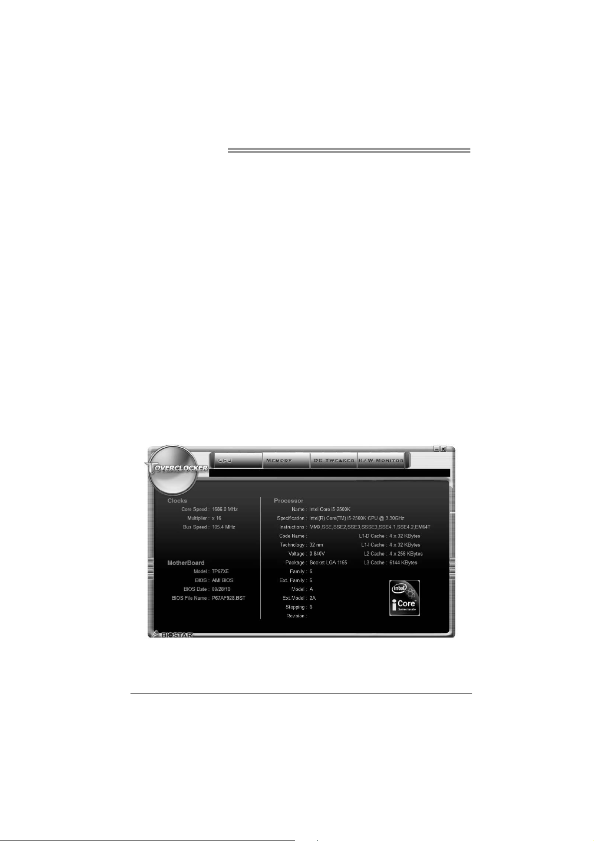
TOverclocker
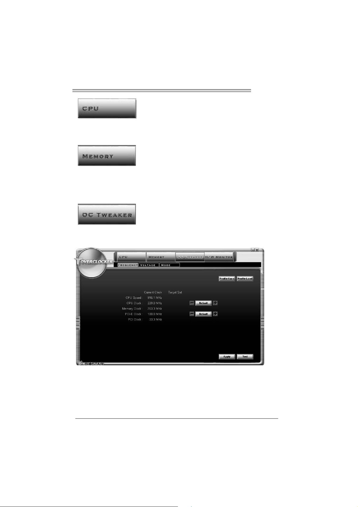
TOverclocker presents a simple Windows-based system performance
enhancement and manageability utility. It features several powerful and easy
to use tools such as Overclocking for enhancing system performance, also for
special enhancement on CPU and Memory. Smart-Fan management and PC
health are for monitoring system status.This utility also allows you to make
overclocking profiles saving unlimitedly, and pre-set OC modes are for easy
OC. (The illustration below is for reference only)
26
Page 29
TP67B+
The CPU tab provides information on the CPU and motherboard.
The Memory tab provides information on the memory module(s).
You can select memory module on a specific slot to see its information.
The OC Tweaker tab allows you to change system clock settings and voltages
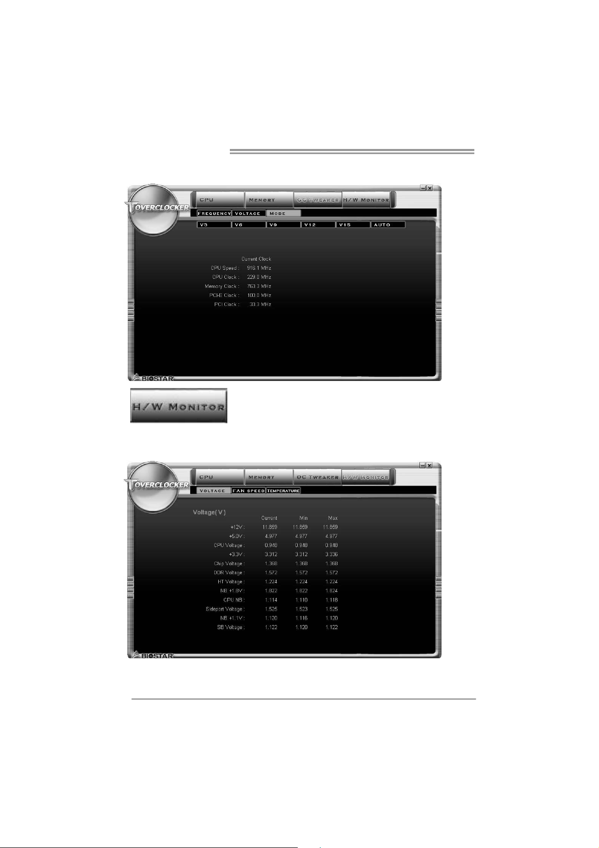
settings. It also provides six pre-set modes for you:
27
Page 30
Motherboard Manual
3 Pre-set Modes: V6, V12, AUTO for different overclocking experience.
The HW Monitor tab allows you to monitor hardware voltage, fan speed, and
temperature. Besides, you also can set related values for CPU Smart Fan.
28
Page 31
TP67B+
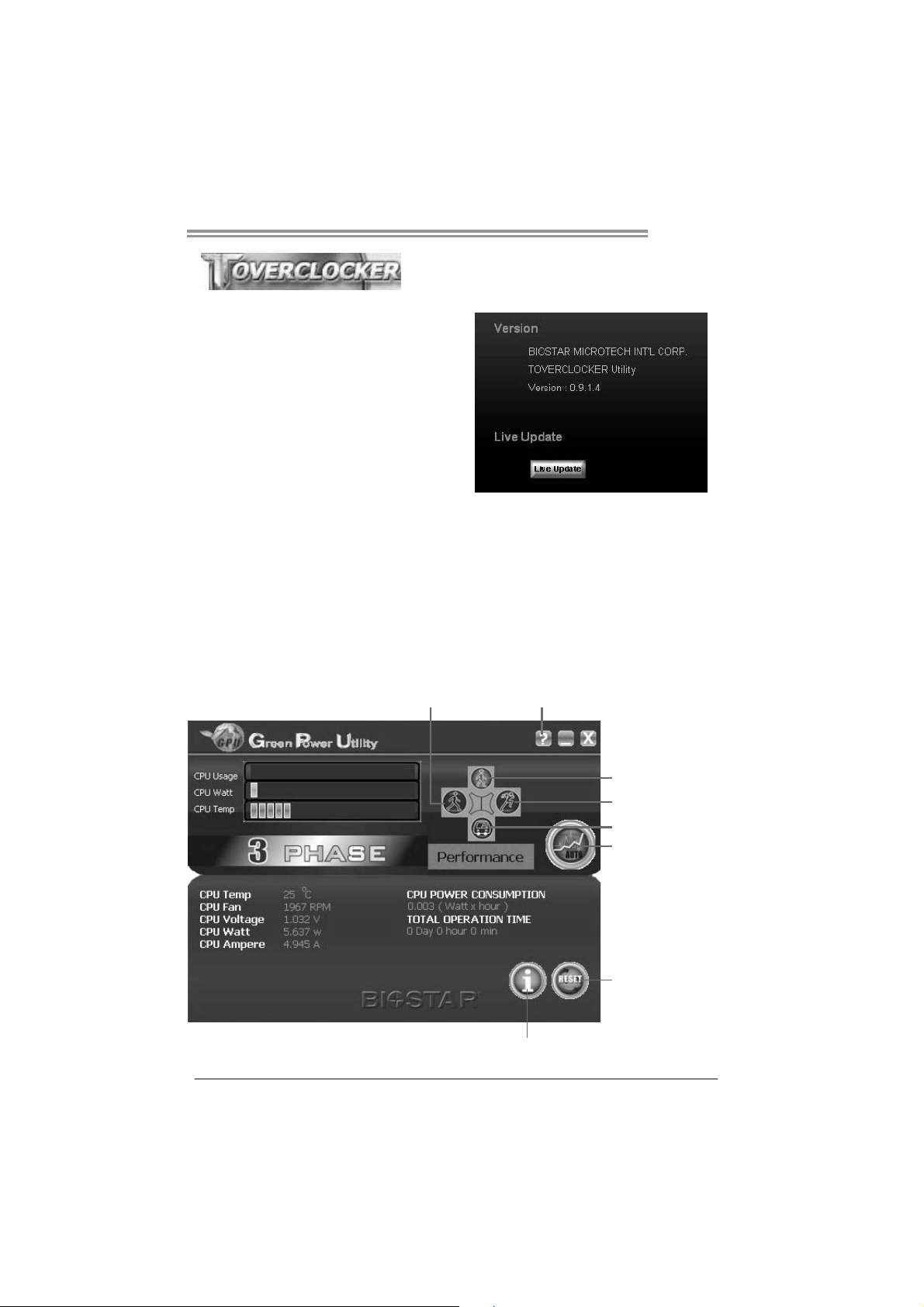
Pressing TOVERCLOCKER logo
displays information about
manufacturer and software version.
You ca n upd ate cur r e nt ver sion by
clicking the button “Live Update.”
Green Power II Utility
BIOSTAR G.P.U II (Green Power Utility) is a new function. The utility enhances
energy efficiency by disabling extra phases while CPU is on light loading; it
features 4+1 power phases, current power saving, and toal power saving. This
tool integrates a friendly GUI to monitor your CPU Usage, CPU Watt, and CPU
Temperature. Moreover, it optimizes power saving and best power efficiency
on your system. (The illustration below is for reference only)
Display manufacturer &
Typical Mode
software version information
Performance
Mode
Medium Mode
Maxi-Energy Mode
Auto Phase Mode
Re set T im e &
Cons um ption
Display CPU
information
29
Page 32

Motherboard Manual
G.P.U Mode Setting
This utility provides five modes, upon your requirements, to improve
system performance or to save power consumption.
Note: Even if the modes saving more power consumption are chosen, the
system still can keep excellent performance.
Auto Phase Mode
System switches the mode automatically according to current system
loading condition.
Performance Mode
This is the mode saving power consumption most. Least energy will
be used in the system.
Typical Mode
Compared with that in Performance Mode, energy consumption in this
mode is a little bit more.
Medium Mode
This is the standard system power saving mode.
Maxi-Energy Mode
This is the best system performance mode.
30
Page 33
TP67B+
e
eHot-Line (Optional)
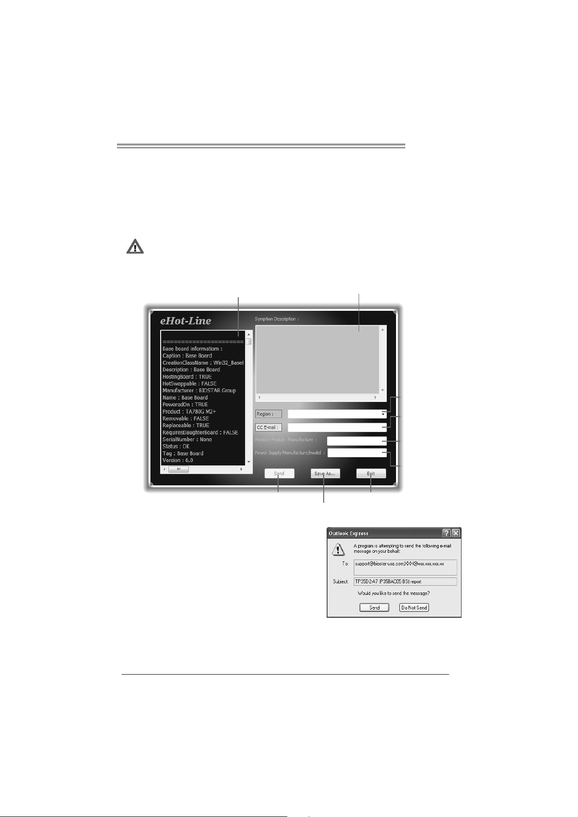
eHot-Line is a convenient utility that helps you to contact with our
Tech-Support system. This utility will collect the system information which is
useful for analyzing the problem you may have encountered, and then send
these information to our tech-support department to help you fix the problem.
Before you use this uti lity, please set Outlook Express as yo ur default e-mail clie nt applica tion program.
rep resents impo rtant
*
information t hat you
must provi de. Withou t
this informat ion, you may
not be able to send ou t
the mail.
This block will show
the infor mation which
would be collect ed in
the mail.
Send the mail ou t.
Describe co ndition
*
of your syst em.
Save these information to a .txt fil
Exit this dialog.
Select your area or
*
the area clos e to yo u.
Provid e the e-mail
addres s that you would
like to send the copy to.
Provide t he name of
*
the memory module
manufactu rer.
Provid e the name of
the power suppl y
manufac tur er and t he
model no .
After filling up this information, click “Send”
to send the mail out. A warning dialog would
appear asking for your confirmation; click
“Send” to confirm or “Do Not Send” to cancel.
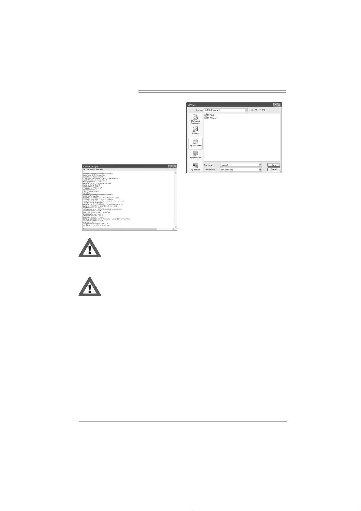
If you want to save this information to a .txt file, click “Save As…” and then you
will see a saving dialog appears asking you to enter file name.
31
Page 34
Motherboard Manual
Enter the file name and then click
“Save”. Your system information
will be saved to a .txt file.
We will not share custo mer ’s data with any other third parties,
so please feel free to provide your system information while using
eHot-Line service.
Open the saved .txt file, you will see
your system information including
motherboard/BIOS/CPU/video/
device/OS information. This
information is also concluded in the
sent mail.
32
If you are not using Outlook Express as your default e-mail client
application, you may need to save the system information to a .txt file
and send the file to our tech support with other e-mail application.
Page 35
BIOS Update
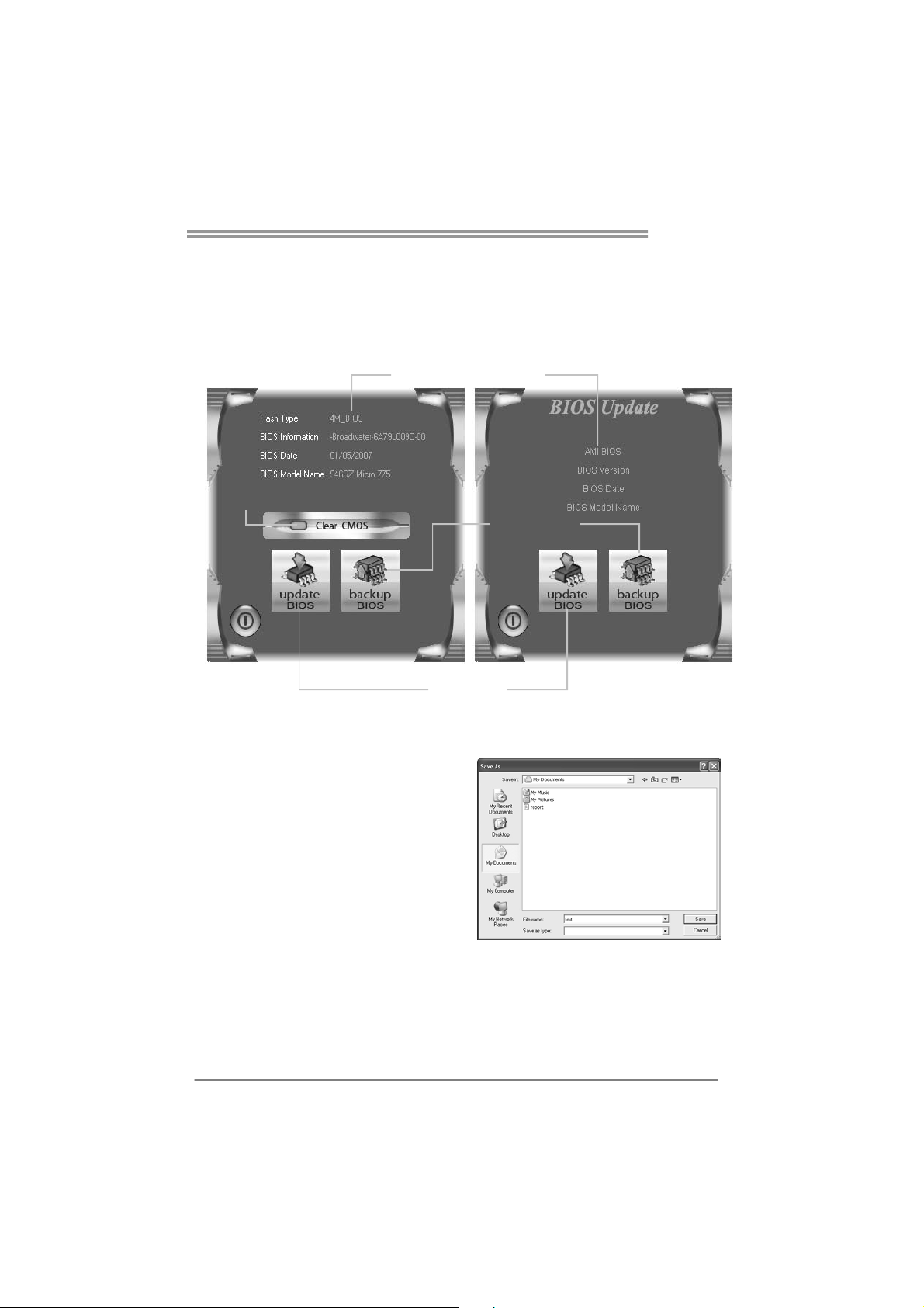
BIOS Update is a convenient utility which allows you to update your
motherboard BIOS under Windows system.
TP67B+
AWARD BIOS AMI BIOS
Clear CMOS function
(Only for AWARD BIOS)
Show current BIOS information
Save cur rent B IOS
to a .bin file
Update BIOS
with a BIOS file
<Backup BIOS>
Once click on this button, the saving
dialog will show. Choose the
position to save file and enter file
name. (We recommend that the file
name should be English/number
and no longer than 7 characters.)
Then click Save.
33
Page 36
Motherboard Manual
<Update BIOS>
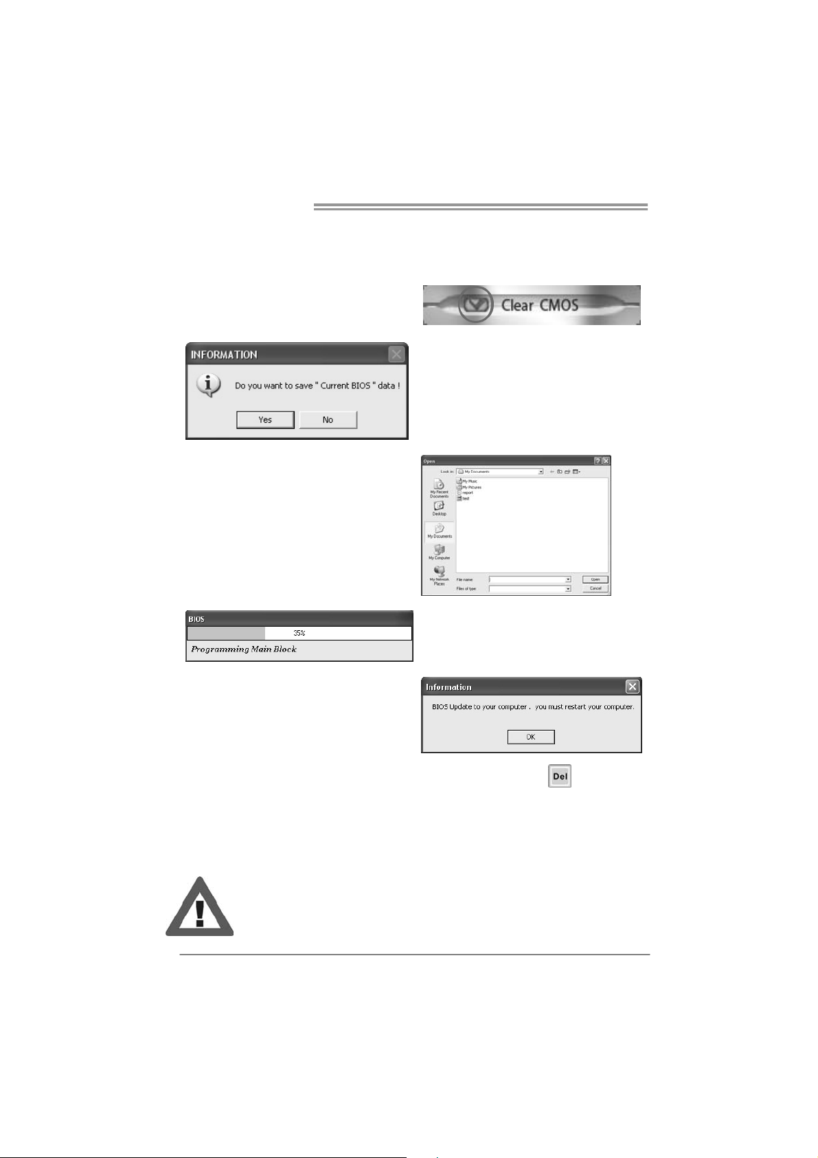
Before doing this, please download the proper BIOS file from the website.
For AWARD BIOS, update BIOS procedure
should be run with Clear CMOS function, so
please check on Clear CMOS first.
Then click Update BIOS button, a
dialog will show for asking you backup
current BIOS. Click Ye s for BIOS
backup and refer to the Backup BIOS
procedure; or click No to skip this
procedure.
After the BIOS Backup procedure, the
open dialog will show for requesting the
BIOS file which is going to be updated.
Please choose the proper BIOS file for
updating, then click on Open.
The utility will update BIOS with the
proper BIOS file, and this process may
take minutes. Please do not open any
other applications during this process.
After the BIOS Update process, click on
OK to restart the system.
While the system boots up and the full screen logo shows, press <Delete>
key to enter BIOS setup.
In the BIOS setup, use the Load Optimized Defaults function and then Save and
Exit Setup to exit BIOS setup. BIOS Update is completed.
All the information and content above about the T-Series software are subject to be
changed without notice. For better performance, the software is being continuously
updated. The information and pictures described above are for your reference only.
The actual i nformation and settings on board may be s lightly different from this
manual.
34
Page 37
TP67B+
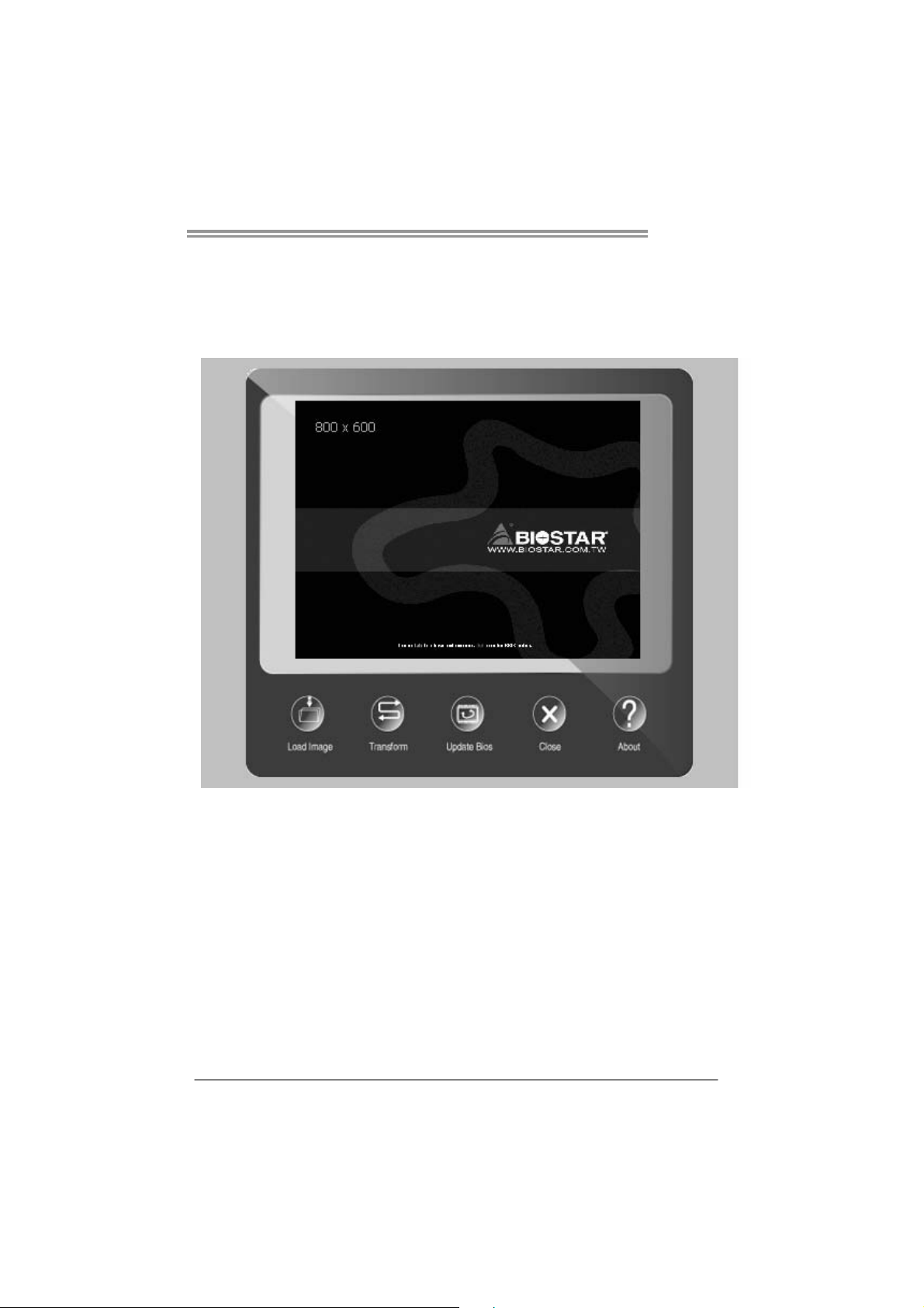
BIOScreen Utility (Optional)
This utility allows you to personalize your boot logo easily. You can choose
JPG or BMP as your boot logo so as to customize your computer.
Please follow the following instructions to update boo logo:
1. Load Image:Choose the picture as the boot logo.
2. Transform:Transform the picture for BIOS and preview the result.
3. Update Bios:Write the picture to BIOS Memory to complete the update.
35
Page 38
Motherboard Manual
CHAPTER 6: USEFUL HELP
6.1 D
RIVER INSTALLATION NOTE
After you installed your operating system, please insert the Fully Setup
Driver CD into your optical drive and install the driver for better system
performance.
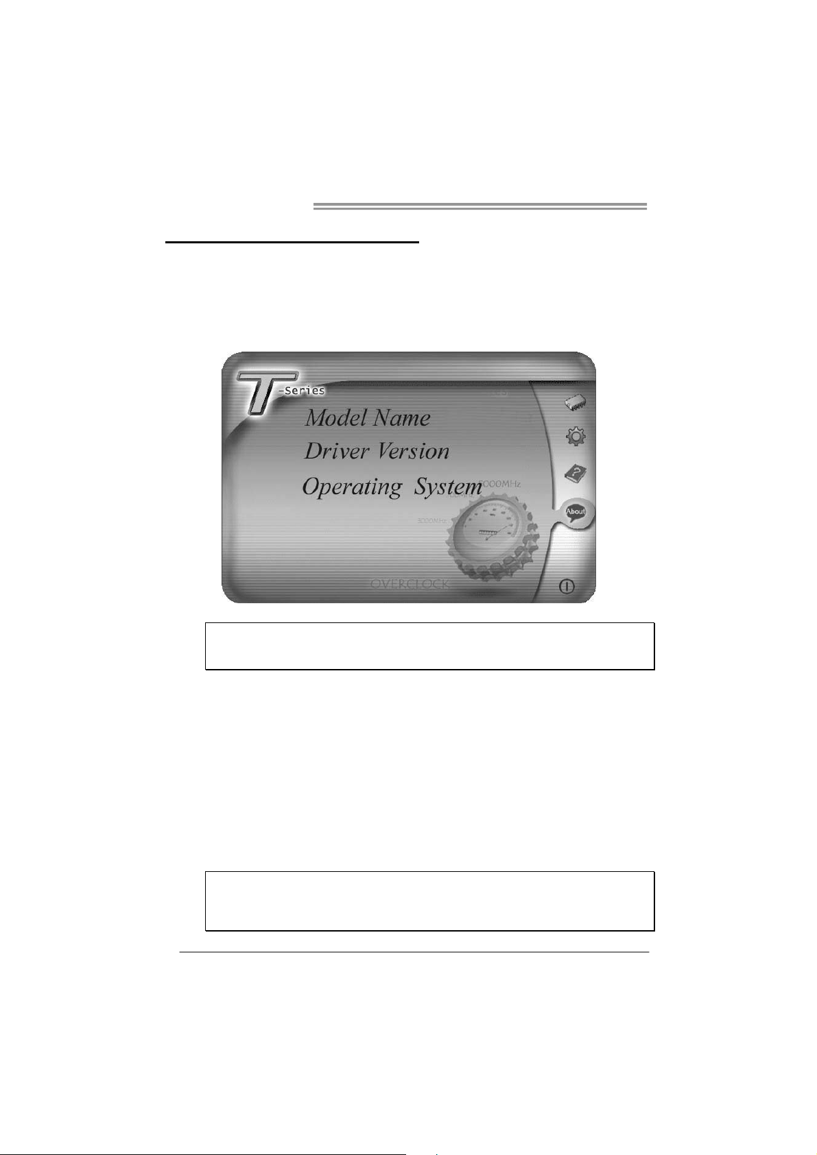
You will see the following window after you insert the CD
The setup guide will auto detect your motherboard and operating system.
Note:
If this window didn’t show up after you insert the Driver CD, please use file browser to
locate and execute the file SETUP.EXE under your optical drive.
A. Driver Installation
To install the driver, please click on the Driver icon. The setup guide will
list the compatible driver for your motherboard and operating system.
Click on each device driver to launch the installation program.
B. Software Installation
To install the software, please click on the Software icon. The setup guide
will list the software available for your system, click on each software title
to launch the installation program.
C. Manual
Aside from the paperback manual, we also provide manual in the Driver
CD. Click on the Manual icon to browse for available manual.
Note:
You will need Acrobat Reader to open the manual file. Please download the latest version
of Acrobat Reader so ftware from
http://www.adobe.com/products/acrobat/readstep2.html
36
Page 39

6.2 EXTRA INFORMATION
CPU Overheated
If the system shutdown automatically after power on system for
seconds, that means the CPU protection function has been activated.
When the CPU is over heated, the motherboard will shutdow n
automatically to avoid a damage of the CPU, and the system may not
power on again.
In this case, please double check:
1. The CPU cooler surface is placed evenly with the CPU surface.
2. CPU fan is rotated normally.
3. CPU fan speed is fulfilling with the CPU speed.
After confirmed, please follow steps below to relief the CPU protection
function.
1. Remove the power cord from power supply for seconds.
2. Wait for seconds.
3. Plug in the power cord and boot up the system.
Or you can:
1. Clear the CMOS data.
(See “Close CMOS Header: JCMOS1” section)
2. Wait for seconds.
3. Power on the system again.
TP67B+
37
Page 40

Motherboard Manual
6.3 TROUBLESHOOTING
Probable Solution
1. There is no power in the system.
Power LED does not shine; the
fan of the power supply does not
work
2. Indicator light on keyboard does
not shine.
System is inoperative. Keyboard lights
are on, power indicator lights are lit,
and hard drives are running.
System does not boot from a hard disk
drive, but can be booted from optical
drive.
System only boots from an optical
drive. Hard disks can be read,
applications can be used, but system
fails to boot from a hard disk.
Screen message shows “Invalid
Configuration” or “CMOS Failure.”
System cannot boot after user installs a
second hard drive.
1. Make sure power cable is
securely plugged in.
2. Replace cable.
3. Contact technical support.
Using even pressure on both ends of
the DIMM, press down firmly until the
module snaps into place.
1. Check cable running from disk to
disk controller board. Make sure
both ends are securely plugged
in; check the drive type in the
standard CMOS setup.
2. Backing up the hard drive is
extremely important. All hard
disks are capable of breaking
down at any time.
1. Back up data and applications
files.
2. Reformat the hard drive.
Re-install applications and data
using backup disks.
Review system’s equipment. Make sure
correct information is in setup.
1. Set master/slave jumpers
correctly.
2. Run SETUP program and select
correct drive types. Call the drive
manufacturers for compatibility
with other drives.
38
Page 41

TP67B+
This page is intentionally left blank.
39
Page 42

Motherboard Manual
APPENDIX: SPEC IN OTHER LANGUAGES
G
ERMAN
Sp ezif ika tio nen
Socket 1155
CPU
Chipsatz
Super E/A
Arbeitsspeich
er
SATA 2 & 3 Integrierter Serial ATA-Controller
LAN Realtek RTL 8111E
HD
Audio-Unters
tützung
USB3.0
Int e l Core i7 / i5 / i3 / Pent iu m / Ce le ron
Prozessoren
Intel P67
IT8728
Biet et die h äufig ver wend eten a lten S up er
E/A-Funktionen.
Low Pin Count-Schnittstelle
DDR3 DIMM-Steckplätze x 4
Max. 16GB Arbeitsspeicher
Jeder DIMM unterstützt 512MB/
1GB/2GB/4GB DDR3.
ALC892
NEC uPD720200 Datenübertragungsraten bis zu 600 MB / s
Unterstützt Execute Disable Bit / Enhanced Intel
SpeedSt ep® / Inte l Ar ch ite cture-64 / Ex tended
Memory 64 Technology / V irtualization Technology /
Hyp er T hr eading
Umgebungskontrolle,
Hardware-Überwachung
Lüfterdrehzahl-Controller/-Überwachung
"Smart Guardian"-Funktion von ITE
Dual-Kanal DDR3 Speichermodul
Unterstützt DDR3 1066 / 1333
Unterstützt DDR3 1600(OC) / 1866 (OC) / 2133(OC )
registrierte DIMMs. ECC DIMMs werden nicht
unterstützt.
Datentransferrate bis zu 3.0Gb/s / 6.0Gb/s.
Konform mit d er SATA-Spezifikation Version 2.0 / 3.0
10 / 100 / 1000 Mb/s Auto-Negotiation
Halb-/ Vollduplex-Funktion
Unterstützt High-Definition Audio
5.1-Kanal-Audioausgabe
PCI-Steckplatz x 2
Steckplätz e
PCI-E Gen2 x 16 @ x16 Steckplatz x1
PCI-E Gen2 x 16 @ x4 Steckplatz x1
PCI-E Gen2 x1-Steckplatz x1
40
Page 43
Onboard-Ans
chluss
TP67B+
Sp ezif ika tio nen
SATA3-Anschluss x2 Jeder Anschluss unterstützt 1 SATA3-Laufwerk
SATA2-Anschluss x4 Jeder Anschluss unterstützt 1 SATA2-Laufwerk
Fronttafelanschluss x1 Unterstützt die Fronttafelfunktionen
Front-Audioanschluss x1 Unterstützt die Fronttafel-Audioanschlussfunktion
CPU-Lüfterstromversorgungsanschluss (mit Smart
CPU-Lüfter-Sockel x1
Fan -F un ktio n)
System-Lüfter-Sockel x2 System-Lüfter-Stromversorgungsanschluss
"CMOS löschen "-Sockel x1
USB2.0-Anschluss x2 Jeder Anschluss unterstützt 2
Front taf el- USB 2.0-A ns chlüsse
Verbraucher-IR Anschluss x1
Serieller Anschluss x1
S/PDIF Ausgangsanschluss x1 Unterstützt die digitale Audioausgabefunktion
Stromanschluss (24-polig) x1
St romansch luss (8-po lig ) x1
Rückseiten-E
/A
Platinengröße
OS-Unterstüt
zung
PS/2-Tastatur x1
PS/2- Maus x 1
S/PDIF Heraus x1
LAN-Anschluss x1
USB2.0-Anschluss x4
USB3.0-Anschluss x2
Audioanschluss x3
305 mm (B) X 220 mm (L) ATX
Windows XP / Vista / 7
USB3.0 Geräte (durch NEC uPD720200)
USB2.0/USB1.X Geräte (durch P67 )
Biostar behält sich das Recht vor, ohne Ankündigung
die Unterstützung für ein Betriebssystem
hinzuzufügen oder zu entfernen.
41
Page 44

Motherboard Manual
FRENCH
SPEC
UC
Chipset
Super E/S
Mémoire
principale
SATA 2 & 3
Socket 1155
Pro c esseurs Int e l Core i7 / i5 / i3 / Pen t iu m /
Celeron
Intel P67
IT8728
Fournit la fonctionnalité de Super E/S
patrimoniales la plus utilisée.
Int e rfa ce à f a ib le co mpt e d e b roches
Fentes DDR3 DIMM x 4
Capacité mé mo ire max i male de 16 Go
Chaque DIMM prend en charge des DDR3 de
512Mo/1Go/2Go/4Go
Contrô leur Serial ATA int é gr é :
Prend en cha rge les techno log ies d'exécution de b it
de désactivation / Intel SpeedStep® optimisée/
d'architectur e Inte l 64 / de mé moire ét endue 64 / de
virtualisation / Hyper Threading
Initiatives de contrôle environnementales,
Mon iteur d e mat ériel
Contrôleur /moniteur de vitesse de ventilateur
Fonction "Gardien intelligent" de l'ITE
Modu le d e mé mo ir e D DR3 à mo d e à dou b le vo ie
Prend en charge la DDR3 1066 / 1333
Prend en charge la DDR3 1600 (OC) / 1866 (OC) /
2133 (OC)
Les DIMM à registres et DIMM avec code correcteurs
d'erreurs ne sont pas prises en charge
Taux de transfert jusqu'à 3.0Go/s / 6.0Go/s.
Conforme à la spécification SATA Version 2.0 / 3.0
LAN
Prise en
charg e
aud io HD
USB3.0
Fentes
42
Realtek RTL 8111E
10 / 100 / 1000 Mb/s négociation automatique
Half / Full duplex capability
Prise en charg e de l' aud io haut e déf in it ion
ALC892
Sortie aud io à 5 .1 voies
NEC uPD720200 Taux de transfert de données jusqu'à 600 Mo / s
Fente PCI x2
Fente PCI-E Gen2 x 16 @ x16 x1
Fente PCI-E Gen2 x 16 @ x4 x1
Fente PCI-E Gen2 x1 x1
Page 45
Connecteur
embarqu é
E/S du
panneau
arrière
Dimensions
de la carte
Support SE
TP67B+
SPEC
Connecteur SATA3 x2
Connecteur SATA2 x4
Connecteur du panneau avant x1 Prend en charge les équipements du panneau avant
Connect eur Audio du panne au avant x 1 Prend en charge la fonct ion aud io du pann eau avant
Embase de ventilateur UC x1
Embase de ventilateur système x2 Alimentation électrique du ventilateur système
Embase d'effacement CMOS x1
Connecteur USB2.0 x2
Connecteur de IR du consommateur x1
Port série x1
Connecteur de sortie S/PDIF x1
Connecteur d'aliment at ion x1
(24 broches)
Connecteur d'aliment at ion x1
(8 broch es)
Clavier PS/2 x1
Souris PS/2 x1
Sortie S/PDIF x1
Port LAN x1
Port USB2.0 x4
Port USB3.0 x2
Fiche aud io x3
305 mm (l) X 220 mm (H) ATX
Windows XP / Vista / 7
Chaque connecteur pr end en charg e 1 périphérique
SATA3
Chaque connecteur pr end en charg e 1 périphérique
SATA2
Alimentation électrique du ventilateur UC (avec
fonction de ventilateur intelligent)
Chaque connecteur prend en charge 2 ports USB2.0
de panneau avant
Prend en charge la fonction de sortie audio
numérique
USB3.0 dispositifs (par NEC uPD720200)
USB2.0/USB1.X dispositifs (par P67)
Biostar se réserve le droit d'ajouter ou de supprimer
le support de SE avec ou sans pr éavis
43
Page 46

Motherboard Manual
ITALIAN
SPECIFICA
CPU
Chipset
Super I/O
Memoria
principale
SATA 2 & 3
Socket 1155
Pro ces s o re Intel Cor e i7 / i5 / i3 /
Pentium / Celeron
Intel P67
IT8728
Fo rnis ce le fun z ionalit à lega cy Super I/O
usate più comunemente.
Interfaccia LPC (Low Pin Count)
Alloggi DIMM DDR3 x 4
Capacità massima della memoria 16GB
Ciascun DIMM supporta DDR3
512MB/1GB/2GB/4GB
Co ntroller S erial ATA integrat o
Supporto di Ex ecute Disable Bit / Enhanced
Intel SpeedStep® / Architettura Intel 64 /
Tecnologia Extended Memory 64 / Tecnologia
Virtualization / Hyper Threading
Funzioni di controllo dell’ambiente:
Monitoraggio hardware
Co ntroller / Mo nitorag g io ve lo cit à ventolina
Funzione "Smart Guardian" di ITE
Modulo di memoria DDR3 a canale doppio
Supporto di DDR3 1066 / 1333
Supporto di DDR3 1600 (OC) / 1866 (OC) /
2133 (OC)
DIMM r egistrati e DIMM ECC non sono
supportati
Velocità di trasferimento dei dati fino a 3.0Gb/s
/ 6.0Gb/s.
LAN
Supporto
audio HD
USB3.0
Allo g gi
44
Compatibile specifiche SATA Versione 2.0/3.0
Negoziazione automatica 10 / 100 / 1000 Mb/s
Realtek RTL 8111E
Capacità Half / Full Dup lex
Supporto audio High-Definition (HD)
ALC892
Uscita audio 5.1 canali
NEC uPD720200 Velocità di trasferimento dati fino a 600 MB / s
Allo g gio PC I x 2
Allo g gio PCI-E Gen2 x16 @ x16 x1
Allo g gio PCI-E G en 2 x16 @ x4 x 1
Alloggio PCI Express Gen2 x1 x1
Page 47
Connettori
su scheda
I/O
pannello
posteriore
Dimension
i scheda
Sistemi
operat ivi
supportati
TP67B+
SPECIFICA
Connettore SATA3 x2 Ciascun connettore supporta 1 unità SATA3
Connettore SATA2 x4 Ciascun connettore supporta 1 unità SATA2
Co nnett ore pann ello fro n tale x 1 S upport a i s ervizi de l p an nello fro ntale
Connettore audio frontale x1 Supporta la funzione audio pannello frontale
Co llett o re vent o lina C PU x 1
Co llett o re vent o lina s is t em a x 2 Alimentazione ven tolin a d i sistema
Co llett o re cancellaz io ne CMOS x 1
Connettore USB2.0 x2
Connettore IR del consumatore x1
Porta seriale x1
Connettore output S/PDIF x1 Supporta la funzione d’output audio digitale
Connettore alimentaz ione x1
(24 pin)
Connettore alimentazione x 1
(8 pin)
Tas t i era PS /2 x 1
Mou s e PS/2 x 1
S/PDIF Fuori x1
Porta LAN x1
Porta USB2.0 x4
Porta USB3.0 x2
Connettore audio x3
305 mm (larghezza) x 220 mm
(altez za)
Windows XP / Vista / 7
Alimentazione ventolina CPU (con funzione
Smart Fan)
Ciascun connettore supporta 2 porte USB2.0
pannello frontale
USB3.0 dispositivi (da NEC uPD720200)
USB2.0/US B1.X dis positivi (da P67)
ATX
Biostar si riserva il diritto di aggiungere o
rimuovere il supporto di qualsiasi sistema
operativo senza preavviso.
45
Page 48

Motherboard Manual
SPANISH
Especificación
CPU
Conjunto de
chips
Súper E/S
Memoria
principal
SATA 2 & 3
Socket 1155
Pro c esador In tel Cor e i7 / i5 / i3 / Pent iu m /
Celeron
Intel P67
IT8728
Le ofrece las funcionalidades heredadas de
us o más común S úper E/S.
Interfaz de cuenta Low Pin
Ranuras DIMM DDR3 x 4
Capacidad máxima de memoria de 16GB
Cada DIMM admite DDR de
512MB/1GB/2GB/4GB
Controlador ATA Serie Integrado
Admite Bit de d eshabilitación de ejecución / Intel
SpeedSt ep® Mejorado / Int el Architecture- 64 /
Tecnolog ía Extended Memor y 64 / Tecno log ía de
virtualizac ión / Hyper Thr ead ing
In iciat ivas d e co ntro l d e ent o rno ,
Monitor hardware
Controlador/monitor de velocidad de ventilador
Función "Guardia inteligente" de ITE
Módulo de memoria DDR3 de canal Doble
Admite DDR3 de 1066 / 1333
Admite DDR3 de 1600(OC) / 1866(OC) / 2133(OC)
No admite DIMM registrados o DIMM compatibles
con ECC
Tasas de transferencia de hasta 3.0 Gb/s / 6.0 Gb/s.
Co mp at ible co n la vers ió n SATA 2.0 / 3 .0.
Red Local
Soporte de
sonido HD
USB3.0
Ranuras
46
Realtek RTL 8111E
Negociación de 10 / 100 / 1000 Mb/s
Funciones Half / Full dúplex
Soporte de sonido de Alta Definición
ALC892
Salida de sonido de 5.1 canales
NEC uPD720200 Tasas de transferencia de datos hasta 600 MB / s
Ranura PCI X2
Ranura PCI-E Gen2 x16 @ x16 X1
Ranura PCI-E Gen2 x16 @ x4 X1
Ranura PCI-E Gen2 x 1 X1
Page 49
Conectores
en p laca
Panel
trasero de
E/S
Ta maño d e
la placa
Soporte de
sistema
operativo
TP67B+
Especificación
Conector SATA3 X2 Cada conector soporta 1 dispositivos SATA3
Conector SATA2 X4 Cada conector soporta 1 dispositivos SATA2
Co necto r de p ane l f ron tal X1 S o port a in s talaciones en e l p ane l front a l
Conector de sonido frontal X1 Soporta funciones de sonido en el panel frontal
Cabecera de ventilador de CPU X1 Fuente de alimentación de ventilador de CPU (con
función Smart Fan)
Cabecera de ventilador de sistema X2 Fuente de alimentación de ventilador de sistema
Cabecera de borrado de CMOS X1
Conector USB2.0 X2 Cada conector soporta 2 puertos USB2.0 frontales
Conector de IR del consumidor X1
Puert o ser ie X1
Conector de salida S/PDIF X1 Soporta función de salida de sonido digital
Conector de alimentación X1
(24 patillas)
Conector de alimentación X1
(8 patillas)
Tec lad o P S /2 X1
Ratón PS/2 X1
Salida S/PDIF x1
Puerto de red local X1
Puert o USB2.0 X4
Puert o USB3.0 X2
Conector de sonido X3
305 mm. (A) X 220 Mm. (H) ATX
Windows XP / Vista / 7
USB3.0 dispositivos (por NEC uPD720200)
USB2.0/USB1.X dispositivos (por P67)
Biostar se reserva el derecho de añadir o retirar el
soporte de cualquier SO con o sin aviso previo.
47
Page 50

Motherboard Manual
PORTUGUESE
ESPECIFICAÇÕES
Socket 1155
CPU
Chipset Intel P67
Especificaçã
o Super I/O
Memória
principal
SATA 2 & 3 Controlador Serial ATA integrado
LAN Realtek RTL 8111E
Suporte
para áudio
de alta
definição
USB3.0
Ranhuras
Pro c essador Int e l Core i7 / i5 / i3 / Pent iu m /
Celeron
IT8728
Proporciona as funcionalidades mais
utilizadas em termos da especificação Super
I/O.
Interface LPC (Low Pin Count).
Ranhuras DIMM DDR3 x 4
Capacidad e máx ima d e memória: 16 GB
Cada módulo DIMM suporta uma memória
DDR3 de 512MB/ 1GB/2GB /4GB
ALC892
NEC uPD720200 Taxas de transferência de dados até 600 MB / s
Ranhura PCI x2
Ranhura PCI-E Gen2 x16 @ x16 x1
Ranhura PCI-E Gen2 x16 @ x4 x1
Ranhura PCI-E Gen2 x 1 x1
Suporta as tecno logias Ex ecut e Disab le B it /
Enhanced Int el SpeedStep® / Inte l Arqu itect ure - 64
/ Extended Memor y 64 / Virtualization / Hyper
Thread ing
In iciat ivas p ar a con t ro lo do amb ient e
Monitorização do hardware
Controlador/Monitor da velocidade da ventoinha
Função "S mart Gu ardian" d a ITE
Módulo de memória DDR3 de canal duplo
Suporta módulos DDR3 1066 / 1333
Suporta módulos DDR3 1600 (OC) / 1866 (OC) /
2133 (OC)
Os módulos DIMM registados e os DIMM ECC não
são suportados
Velocidades de transmissão de dados até 3.0 Gb/s /
6.0 Gb/s.
Compat ib ilidade co m a esp ecif ica ção SATA versão
2.0 / 3.0.
Auto negociação de 10 / 100 / 1000 Mb/s
Capacidade semi/full-duplex
Suporta a especificação High-Definition Audio
Saída de áudio de 5.1 canais
48
Page 51
Conectores
na placa
Entradas/S
aídas no
painel
traseiro
Tamanho
da placa
Sistemas
operativos
suportados
TP67B+
ESPECIFICAÇÕES
Conector SATA3 x2 Cada conector suporta 1 dispositivo SATA3
Conector SATA2 x4 Cada conector suporta 1 dispositivo SATA2
Conector do painel frontal x1 Para suporte de várias funções no painel frontal
Conector de áud io frontal x1 Suporta a fun ção de áud io no paine l fronta l
Conector da ventoinha da CPU x1
Conector da ventoinha do sistema x2 Alimentação da ventoinha do s istema
Conector para limpeza do CMOS x1
Conector USB2.0 x2
Conector de IR do consumidor x1
Porta série x1
Conector de saída S /PDIF x 1 Supo rta a saída de áudio d ig ita l
Conector de alimentação x1
(24 pinos)
Conector de alimentação x1
(8 p inos)
Tec lad o P S /2 x1
Rato PS/2 x1
Saíd a S/PDIF x1
Porta LAN x1
Porta USB2.0 x 4
Porta USB3.0 x 2
Tomada de áudio x3
305 mm (L) X 220 mm (A) ATX
Windows XP / Vista / 7
Alimentação da ventoinha da CPU (com a função
Smart Fan)
Cada conector suporta 2 portas USB2.0 no painel
frontal
USB3.0 dispositivos (por NEC uPD720200)
USB2.0/USB1.X dispositivos (por P67)
A Biostar reserva-se o direito de adicionar ou
remover suporte para qualquer sistema operativo
com ou sem av is o prévio.
49
Page 52

Motherboard Manual
POLISH
SPEC
Procesor
Chipset
Pamięć
główna
Super I/O
SATA 2 & 3
Socket 1155
Pro c esor Int e l Core i7 / i5 / i3 / Pent iu m /
Celeron
Intel P67
Gniazda DDR3 DIMM x 4
Maks. wielkość pamięci 16GB
Każde gniazdo DIMM obs ługuje moduły
512MB/1GB/2GB/4GB DDR3
IT8728
Zapewnia najbardziej powszechne funkcje
Super I/O.
Interfejs Low Pin Count
Zintegrowany kontroler Serial ATA
Obsługa Execute D is able B it / Enhanced Intel
SpeedSt ep® / Inte l Ar ch ite cture-64 / Ex tended
Memory 64 Technology / V irtualization Technology /
Hyp er T hr eading
Mod uł pamięci DDR3 z trybem podwójnego kanału
Obsługa DDR3 1066 / 1333
Obsługa DDR3 1600 (OC) / 1866 (OC) / 2133 (OC)
Brak obsług i Register ed DIMM oraz ECC DIMM
Funkcje kontroli warunków pracy,
Mon itor H /W
Kontroler/Monitor prędkości wentylatora
Funkcja ITE "S mart Gu ard ian"
Transfer danych do 3.0 Gb/s / 6.0 Gb/s.
Zgodność ze specyfikacją SATA w wersji 2.0 / 3.0.
10 / 100 / 1000 Mb/s z automatyczną negocjacją
LAN
Obsługa
aud io HD
USB3.0
Gniazda
50
Realtek RTL 8111E
ALC892
NEC uPD720200 Cena transferu danych do 600 MB / s
Gniazdo PCI x2
Gniazdo PCI-E Gen2 x16 @ x16 x1
Gniazdo PCI-E Gen2 x16 @ x4 x1
Gniazdo PCI-E Gen2 x 1 x1
szybkości
Działanie w tryb ie połowicznego / pełnego dupleksu
Obsługa H ig h-Definition A ud io
5.1 kanałowe wyjście audio
Page 53
Złącza
wbud owane
Back Panel
I/O
Wymiary
płyty
Obsluga
systemu
operacyjne
go
TP67B+
SPEC
Złącze SATA3 x2 Każde złącze obs ługuje 1 urządzenie SATA3
Złącze SATA2 x4 Każde złącze obs ługuje 1 urządzenie SATA2
Złącze panela przedniego x1 Obsługa elementów panela przedniego
Przedn ie złącze aud io x1 Obsługa funkcji audio na panelu przednim
Złącze główkow e went ylatora
procesora x1
Złącze główkow e went ylatora
systemowego x2
Złącze główkowe kasowan ia CMOS x1
Złącze USB2.0 x2
Złącze Konsument IR x1
Port szeregowy x1
Złącze wyjścia S/PDIF x1 Obsługa funkcji cyfrowego wyjścia audio
Złącze zasilania (24 pinowe) x1
Złącze zas ilania (8 p ino we) x1
Klawiatura PS/2 x1
Mys z PS /2 x1
wyjścia S/PDIF x1
Port LAN x1
Port USB2.0 x4
Port USB3.0 x2
Gniazdo audio x3
305 mm (S) X 220 mm (W) ATX
Windows XP / Vista / 7
Zasilanie wentylatora procesora (z funkcją Smart
Fan )
Zasilanie wentylatora systemowego
Każde złącze obs ługuje 2 porty USB2.0 na panelu
przednim
USB3.0 urz ądzeń (przez NEC uPD720200)
USB2.0/USB1.X urządzeń (przez P67)
Biostar zastrzega sobie prawo dodawania lub
odwoływ ania obsłu g i dowo ln ego s ys t emu
operacyjnego bez powiado mienia.
51
Page 54

Motherboard Manual
RUSSIAN
CPU
(центральн
ый
процессор)
Набо р
микросхем
Основная
память
Super I/O
SATA 2 & 3
Локальная
сеть
Звуко вая
поддержка
жесткого
диска
USB3.0
Слоты
Socket 1155
Процессор Inte l Cor e i7 / i5 / i3 / Pent iu m /
Celeron
Intel P67
Слоты DDR3 DIMM x 4
Максимальная ёмкость памяти 16 ГБ
Каждый модуль DIMM поддерживает
512МБ /1ГБ/2ГБ/4ГБ DDR3
IT8728
Обеспечивает наиболее используемые
действующие фун кцио нальные
возможно сти Super I/O.
Интерфейс с низким коли чест вом выво до в
Встроенное последовательное устро йство
управления ATA
Realtek RTL 8111E
ALC892
NEC uPD720200 скорости передачи данных до 600 МБ / с
Слот PCI x2
Слот PCI-E Gen2 x16 @ x16 x1
Слот PCI-E Gen2 x16 @ x4 x1
Слот PCI-E Gen2 x 1 x1
СПЕЦ
Поддержка технологий Execut e D isab le Bit /
Enhanced Inte l SpeedStep® / Intel Arch it ecture-64
/ Extended Memory 64 Technology / технологии
виртуализац ия / Hyper Threading
Мод уль памяти с двух канальн ым режимом DDR3
Поддержка DDR3 1066 / 1333
Поддержка DDR3 1600(OC) / 1866(OC) / 2133(OC)
Не поддерживает зарегистрированные модули
DIMM and ECC DIMM
Инициативы по охране окружающей среды,
Аппаратный монитор
Регул ятор скорости вентилято ра/ монитор
Функция ITE "Smart Guard ian"
(Интеллектуальная защита)
скорость передачи данных до 3.0 гигабит/с /
6.0 гигабит/с.
Соответствие спецификации SATA версия 2.0/3.0
Автоматическое согласование 10 / 100 / 1000
Мб/с
Частичная / полная дуплексная способность
Звуко вая поддержка High- D ef inition
5.1канальный звуковой выход
52
Page 55
Встроенны
й разъём
Задняя
панель
средств
ввода-выв
ода
Размер
панели
Поддержка
OS
TP67B+
СПЕЦ
Разъ ём SATA3 x2 Каждый разъём поддерживает 1 устройство SATA3
Разъ ём SATA2 x4 Каждый разъём поддерживает 1 устройство SATA2
Разъ ём на лицевой панели x1 Поддержка устройс тв на лицевой панели
Входной звуковой разъём x1
Контактирующее приспособление
вентил ятора центрального процессора x1
Контактирующее приспособление
вентил ятора системы x2
Открытое контактирующее
приспособление CMOS x1
USB2.0-разъём x2
Разъ ём едок а ИКЫЙ x1
Последоват ельный порт x1
Разъ ём вывода для S/PDIF x1 Поддержка вывода цифровой звуковой функц ии
Разъ ем питания (24 вы вод) x1
Разъ ем питания (8 вывод) x2
Клавиатура PS/2 x1
Мышь PS/2 x1
вывод а для S/PDIF x1
Порт LAN x1
USB2.0-порт x4
USB3.0-порт x2
Гнездо для подключения
наушников x3
305 мм (Ш) X 220 мм (В) ATX
Windows XP / Vista / 7
Поддержка звуко вых функций на лицевой
панели
Источник питания для вентилятор а центрального
процессора (с функц ией интеллектуального
вентил ятора)
Источник пит ания для вентилятора системы
Каждый разъём поддерживает 2 USB2.0-порта на
лицевой панели
USB3.0 устройств (по NEC uPD720200)
USB2.0/USB1.X ус тройств (по P67)
Biostar сохраняет за собой право добавлять или
удалять средства обеспечения для OS с или без
предварительного уведомле ния .
53
Page 56

Motherboard Manual
ARABIC
تﺎﻔﺻاﻮﻤﻟا
تﺎﻴﻨﻘﺗ ﻢﻋﺪﺗExecute D isab le B it / Enhanced Intel
SpeedSt ep® / Inte l Ar ch ite cture-64 / Ex tended
تﺎﺠﻟﺎﻌﻣ Int e l Co r e i7 / i5 / i3 / Pentium /
Memory 64 Technology / Virtualization Technology /
Hyp er T hr eading
Intel P67
Socket 1155
Celeron ﺑ ددﺮﺘ ی ﻰﻟإ ﻞﺼ
ةﺮآاذ ةﺪﺣوDDR3 ﻘﻟا ﺔﺝودﺰﻣةﺎﻨ
ﺔﺤﺘﻓDDR3 DIMM دﺪﻋ4
ىﻮﺼﻗ ةﺮآاذ ﺔﻌﺳ16 ﺖیﺎﺑ ﺎﺠﻴﺝ
ﺔﺤﺘﻓ ﻞآ ﻢﻋﺪﺗDIMM عﻮﻥ ﻦﻣ ةﺮآاذ ﻢﻋﺪﺗ DDR3 ﺔﻌﺳ
ﺔﻔﻴﻇو"S mart Guard ian" ﻦﻣ ITE
ﻞﻘﻧ تﺎﻧﺎﻴﺒﻟا تﺎﻋﺮﺴﺑ ﻞﺼﺗ ﻰﻟإ 3.0 ﺖﺑﺎﺠﻴﺝ/ ﺔﻴﻧﺎﺛ / 6.0
ﺔﻘﺑﺎﻄﻣ تﺎﻔﺹاﻮﻤﻟ SATA راﺪﺹﻹا 2.0 / 3.0.
/512 و ﺖیﺎﺑ ﺎﺠﻴﻣ 1/
ﺖﺑﺎﺠﻴﺝ/ ﺔﻴﻧﺎﺛ.
عﻮﻥ ﻦﻣ ةﺮآاﺬﻟا ﻢﻋﺪﺗDDR3 تﺎﻌﺳ 1066 / 1333ﺖیﺎﺑ ﺎﺠﻴﻣ
ﻢﻋﺪﺗ ةﺮآاﺬﻟا ﻦﻣ عﻮﻧ DDR3 تﺎﻌﺳ 1866 (OC) / 2133
(OC) / 160 0(OC) ﺎﺠﻴﻣ ﺖیﺎﺑ
و2/و 4 ﺎﺠﻴﺝﺖیﺎﺑ
ةﺮآاﺬﻟا ﻖﺋﺎﻗر ﻢﻋﺪﺗ ﻻDIMM ﻊﻣ ﻖﻓاﻮﺘﺗ ﻻ ﻲﺘﻟا ﻚﻠﺗو ECC
ﻞﺋﺎﺳو ﻢﻜﺤﺘﻟا ﻲﻓ ﺔﺌﻴﺒﻟا:
IT8728
ﺐﻗاﺮﻣ ﺔﻓﺮﻌﻤﻟ ﺔﻟﺎﺣ ةﺰﻬﺝﻷا
ﺮﻓﻮﺗ ﺔﻔ ﻴﻇو Super I/O ﺮﺜآﻷا ًﺎﻣ ا ﺪ ﺨ ﺘ ﺳا.
ﺐﻗاﺮﻣ ﻲﻓ ﺔﻋﺮ ﺳ ﺔﺣوﺮﻤﻟا
ﺗﻢﻋﺪ ﺔﻴﻨﻘ ﺗ Low Pin Count Interface
ﻢﻜﺤﺘﻣ Serial ATA ﻞﻣﺎﻜﺘﻣ
ةﺪﺣو ﺔﺠﻟﺎﻌﻤﻟا
ﺔیﺰآﺮﻤﻟا
ﺔﻋﻮﻤﺠﻣ ﺢﺋاﺮﺸﻟا
ةﺮآاﺬﻟا ﺔﻴﺴﻴﺋﺮﻟا
Super I/O
SATA 2 & 3
تﻻﺪﻌﻣ ﻖﻧل تﺎﻧﺎﻴﺑ ﻞﺼﺗ ﻰﻟإ 600 ﺎﻐﻴﻣ ﺖیﺎﺑ / ﺔﻴﻧﺎﺛ
ةﺰﻬﺝأ ﻦﻣ ﺪﺣاو ﺬﻔﻨﻣ ﻞآ ﻢﻋﺪیSATA3 ﺬﻔﻨﻣSATA3 دﺪﻋ2
54
ضوﺎﻔﺗ ﻲﺋﺎﻘﻠﺗ 10/100 ﺎﺠﻴﻣ ﺖیﺎﺑ /ﺔﻴﻥﺎﺙ و1ﺎﺠﻴﺝ ﺖﺑ/ﺔﻴﻥﺎﺙ
ﺔﻴﻥﺎﻜﻣإ ﻞﻘﻨﻟ ا جودﺰﻤﻟا ﻞﻣﺎﻜﻟا/ﻲﻔﺼﻨﻟا
ﻢﻋﺪﺗ ﺔﻴﻨﻘﺗ تﻮﺼﻟا ﻲﻟﺎﻋ ﻒیﺮﻌﺘﻟا ﻦﻣ
5.1 تاﻮﻨﻗ جﺮﺨﻟ تﻮﺼﻟا
ﺔﺤﺘﻓPCI دﺪﻋ2
ﺔﺤﺘﻓPCI-E Gen2 x16 @ x16 دﺪﻋ1
ﺔﺤﺘﻓPCI-E Gen2 x16 @ x4 دﺪﻋ1
ﺔﺤﺘﻓPC I-E Ge n2 x 1 دﺪﻋ1
Realtek RTL 8111E
ALC892
NEC uPD720200
ﺔﻜﺒﺵ ﺔﻴﻠﺥاد
ﻢﻋد تﻮﺼﻟا ﻲﻟﺎﻋ
ﻒیﺮﻌﺘﻟا
USB3.0
تﺎﺤﺘﻔﻟا
ﺬﻓﺎﻨﻤﻟا ﻰﻠﻋ ﺢﻄﺳ
Page 57
تﺎﻔﺻاﻮﻤﻟا
ﺪی ةﺰﻬﺝأ ﻦﻣ ﺪﺣاو ﺬﻔﻨﻣ ﻞآ ﻢﻋSATA2 ﺬﻔﻨﻣSATA2 دﺪﻋ4
ﺔﻴﻣﺎﻣﻷ ا ﺔﺣﻮﻠﻟا تاﺰﻴﻬﺠﺗ ﻢﻋﺪی ﺔﻴﻣﺎﻣﻷا ﺔﺣﻮ ﻠﻟا ﺬﻔﻨﻣ دﺪﻋ1
ﺔﻴﻣﺎﻣﻷا ﺔﺣﻮ ﻠﻟﺎ ﺑ تﻮﺼﻟا ﺔﻔﻴﻇو ﻢﻋﺪی ﻲﻣﺎﻣﻷا تﻮﺼﻟا ﺬﻔﻨﻣ دﺪﻋ1
ﺔﻔﻴﻇو ﻊﻣ ﺔﺠﻟﺎﻌﻤﻟا ةﺪﺣو ﺔﺣوﺮﻤﻟ ﺔﻗﺎﻄﻟا ﻞﻴﺹﻮﺘﻟSmart Fan ﺔیﺰآﺮﻤﻟا ﺔﺠﻟﺎﻌﻤﻟا ةﺪﺣو ﺔﺣوﺮﻣ ﺔﻠﺹو دﺪﻋ1
مﺎﻈﻨﻟا ﺔﺣوﺮﻤﻟ ﺔﻗﺎﻄﻟا ﻞﻴﺹﻮﺘﻟ مﺎﻈﻨﻟا ﺔﺣوﺮﻣ ﺔﻠﺹو دﺪﻋ2
ﺢﺴ ﻣ ﺔﻠﺹوCMOS دﺪﻋ1
ﻲﺘﺤﺘﻓ ﺬﻔﻨﻣ ﻞآ ﻢﻋﺪیUSB2.0ﺔﻴﻣﺎﻣﻷ ا ﺔﺣﻮﻠﻟﺎﺑ ﺬﻔﻨﻣUSB2.0 دﺪﻋ2
ﺬﻔﻨﻣ ﺔﻜﻠﻬﺘﺴﻣ ﺖﺤﺗ ﺮﻤﺣﻷا دﺪﻋ1
ﻲﻠﺴﻠﺴﺗ ﺬﻔ ﻨﻣ دﺪﻋ1
ﻲﻤﻗﺮﻟا تﻮﺼﻟا جﺮﺥ ﺔﻔﻴﻇو ﻢﻋﺪی جﺮﺥ ﺬﻔﻨﻣS/PDIF دﺪﻋ1
ﺔﻗﺎﻄﻟا ﻞﻴﺹﻮﺗ ﺬﻔﻨﻣ)24سﻮﺑد( دﺪﻋ1
ﺔﻗﺎﻄﻟا ﻞﻴﺹﻮﺗ ﺬﻔﻨﻣ)8ﺲﻴﺑﺎﺑد( دﺪ ﻋ1
TP67B+
ﺔﺣﻮﻠﻟا
ﻆﻔﺘﺤﺗ Biostar ﺎﻬﻘﺤﺑ ﻲﻓ ﺔﻓ ﺎﺿإ وأ ﺔﻟازإ ﻢﻋﺪﻟا يﻷ مﺎﻈﻥ ﻞﻴﻐﺸﺗ رﺎﻄﺥﺈﺑ وأ
نوﺪﺑ رﺎﻄﺥإ.
(NEC uPD720200 ﻦﻣ ﻞﺒﻗ ) ةﺰﻬﺝﻷا USB3.0
(P67 ﻦﻣ ﻞﺒﻗ ) ةﺰﻬﺝﻷا USB2.0/USB1.X
AT X 305 ﻢﻣ)ضﺮﻋ (X 220 ﻢﻣ)عﺎﻔﺗرا(
Windows XP / Vista / 7
ﺢﻴﺗﺎﻔﻣ ﺔﺣﻮﻟPS/2 دﺪﻋ1
سوﺎﻣ PS/2 دﺪﻋ1
S/PDIF Out دﺪﻋ1
ﺔﻴﻠﺤﻣ لﺎﺼﺗا ﺔﻜﺒﺵ ﺬﻔﻨﻣ دﺪﻋ1
ﺬﻓﺎﻨﻣUSB2.0 ﻋ دﺪ4
ﺬﻓﺎﻨﻣ ﻞﺥد/جﺮﺥ
ﺔﺣﻮﻠﻟا ﺔﻴﻔﻠﺨﻟا
ﺬﻓﺎﻨﻣUSB3.0 دﺪﻋ2
تﻮﺹ ﺲﺒﻘﻣ دﺪﻋ36
ﻢﺠﺣ ﺔﺣﻮﻠﻟا
ﻢﻋد ﺔﻤﻈﻥأ ﻞﻴﻐﺸﺘﻟا
55
Page 58

Motherboard Manual
JAPANESE
仕様
CPU
チップセット
メインメモリ
Super I/O
SATA 2 & 3
LAN
Socket 1155
Int e l Cor e i7 / i5 / i3 / Pent iu m / Celeron プロ
セッサ
Intel P67
DDR3 DIMMスロット x 4
最大メモリ容 量16GB
各DIMMは 512MB/1GB/2GB/4GB DDR3をサ
ポート
IT8728
もっとも一般 に使 用されるレ ガシーSuper I/O機
能を採用して いま す。
低ピンカウン トイ ンターフェ イス
統合シリアルATA コントロー ラ
Realtek RTL 8111E
Execute Disable Bit / Enh anc ed Intel SpeedStep® /
Intel Architecture-64 / Extended Memory 64
Technology / Virtualiz ation Technology / Hyper
Thread ingをサポート します
デュアル チ ャン ネルモードDDR3メモリモジ ュール
DDR3 1066 / 1333 をサポート
DDR3 1600(OC) / 1866(OC) / 2133(OC) をサポート
登録済みDIMMとECC DIMMはサポ ートされま せん
環境コントロ ール イニシアチ ブ、
H/Wモニター
ファン速度コ ント ローラ/ モニター
ITE の「スマート ガー ディアン」 機能
最高3.0 Gb/秒 / 6.0 Gb /秒のデー タ転送 速度
SATAバージョン2 .0 / 3.0仕様に準拠 。
10 / 100 / 1000 Mb/秒のオート ネゴシ エーション
半/全二重機能
HDオ ーディ
オのサポート
USB3.0
スロット
56
ALC892
ハイデフィニ ショ ンオーディ オのサポー ト
5.1 チ ャンネルオ ーディ オアウト
NEC uPD720200 データ転送速 度最 大600 MB /秒の
PCIスロット x2
PCI-E Gen2 x16 @ x16スロット x1
PCI-E Gen2 x16 @ x4ス ロット x1
PCI Express Gen2 x 1ス ロット x1
Page 59

オンボードコ
ネクタ
TP67B+
仕様
SATA3コネクタ x2 各コネクタは 1つのSATA3デバイスをサ ポートしま す
SATA2コネクタ x4 各コネクタは 1つのSATA2デバイスをサ ポートしま す
フロントパネ ルコ ネクタ x1 フロントパネ ル機 能をサポー トします
フロントオー ディ オコネクタ x1 フロントパネルオ ーディ オ機能をサ ポートしま す
CPUファンヘッダ x1 CPUファン電源装置(スマートフ ァン 機能を搭載 )
システムファ ンヘ ッダ x2 システ ムファン電 源装置
CMOSクリアヘッダ x1
USB2.0コネ クタ x2
消費者IR コネクタ x1
シリアルポー ト x1
S/PDIFアウトコネ クタ x1 デジタルオー ディ オアウト機 能をサ ポートしま す
電源コネクタ (24 ピン) x1
電源コネクタ (8ピン) x1
各コネクタは 2つのフロ ントパネル USB2.0ポー トをサポ
ートします
背面パネル
I/O
ボードサイズ
OSサポー ト
PS/2キーボード x1
PS/2マウス x1
S/PDIF アウ ト x1
LANポート x1
USB2.0ポー ト x4
USB3.0ポー ト x2
オーディオジ ャッ ク x3
305 mm (幅) X 220 mm (高さ) ATX
Windows XP / Vista / 7
USB3.0デバ イス (で NEC uPD720200)
USB2.0/USB1.Xデバイ ス (で P67 )
Biostarは事前の サポートな しにOSサ ポー トを追加ま たは
削除する権利 を留 保します。
2010/10/27
57
 Loading...