

Page 1

T H 67+ /TH67 UEFI BIOS Man u al
i
UEFI BIOS Setu p.......................................................................................1
1 Main Menu...............................................................................................3
2 Adv anced Menu...... ............ ............ ............ ............ ............ ............ .........4
3 PCIPnP Menu........................................................................................16
4 Boot Menu..............................................................................................21
5 C hipse t Menu.........................................................................................24
6 O.N.E Menu...........................................................................................25
7 Exit Menu...............................................................................................32
Page 2

T H 67+ /TH67 UEFI BIOS Man u al
UEFI BIOS Setup
Introduction
T he purpose of this manual is to describe the settings in the AMI UEFI BIOS S etup
program on this motherboard. The Setup program allows users to modify the basic
system confi gur ation and save these settings to NVRAM .
UEFI BIOS determines what a computer can do without accessing programs from a
disk. This system controls most of the input and output devices such as keyboard,
mouse, s erial po rts an d disk dri ves. B IOS acti vates at th e first s tage of t he bo oti ng
process, loading and executing the operating system. Some additional features, such
as virus and password protection or chipset fine-tuning options are also included in
UEF I BIOS .
T he rest of this manual will to guide you through the options and settings in UEFI
BIOS S etup.
Plug and Play Support
This A MI UE FI BIOS supports the Plug and Play V e r sion 1.0A spe c ification.
EPA Green PC Support
T his AM I UEF I BIOS supports Version 1.03 of the EPA Green P C specifi c ation.
ACPI Supp ort
AMI ACPI UEFI BIOS support Version 1.0/2.0 of Advanced Configuration and
Power interface specification (ACPI). It provides ASL code for power
management and device configuration capabilities as defined in the ACPI
specific ation, developed by Microsoft , Intel and Toshiba.
PCI Bus Support
This AMI UEFI BIOS also supports Version 2.3 of the Intel PCI (Peripheral
Component Interconnect) loc al bus specifi cation.
DRA M Support
DDR3 SD R AM (Do uble D ata Rat e III S ynchronous DR AM) is supported.
1
Page 3
T H 67+ /TH67 UEFI BIOS Man u al
Su ppor t e d CP Us
T his AM I UEF I BIOS supports the Intel CPU.
Using Setup
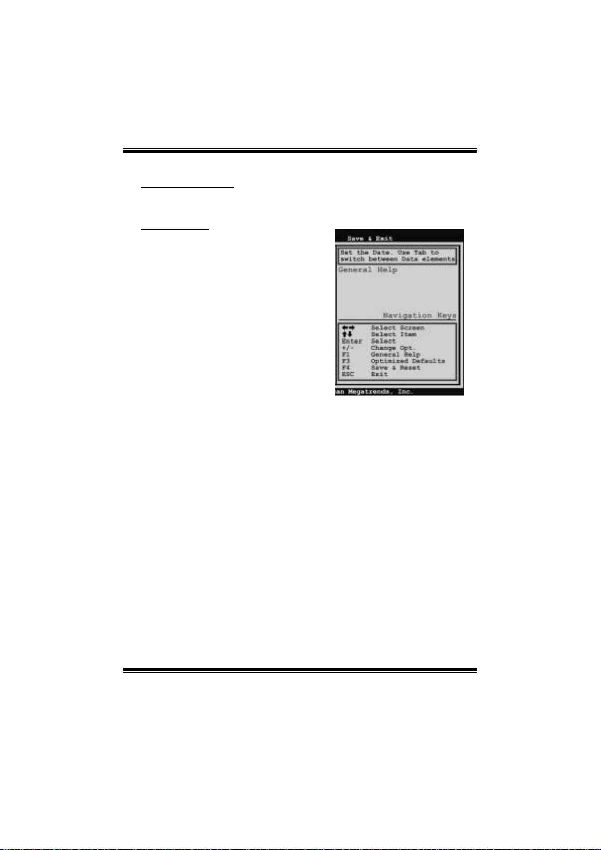
When starting up the computer, press
<Del> during the Power-On Self-Test
(POST) to enter the UEFI BIOS setup
utility.
In the UEFI BIOS setup utility, you will
see General Help description at the top
right corner, and this is providing a brief
description of the selected item.
Navigation Keys for that particular menu
are at t he bottom right corner, and you can
us e thes e keys to select item and ch ange
the settings.
Notice
z The default UEFI BIOS settings apply for most conditions to ensure optimum
perform ance of the motherboard. If the system becomes unstable after changing
any settings, please load the default settings to ensure system’s compatibility and
stability. Use Load Setup Defaul t under t he Exit Menu.
z For better system performance, the UEFI BIOS firmware is being continuously
updated. T he UEFI BIOS information described in this manual is for your refe rence
only. The actual UEFI BIOS information and settings on board may be slightly
di fferent fro m th i s m anual.
z T he content of this manual is subject to be chang ed without notice. W e will not be
responsible for any mi stakes found in this user’s manual and any system damage that
may be caused by wrong-settings.
2
Page 4
T H 67+ /TH67 UEFI BIOS Man u al
1 Main Menu
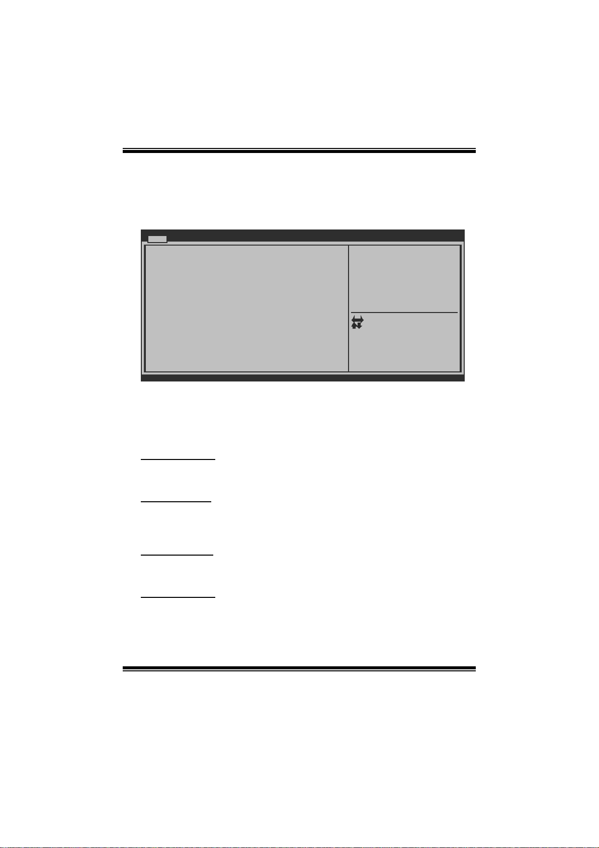
Once you enter AMI UEFI BIOS Setup Utility, the Main Menu will appear on the
scre en providing an overview of the basic syst em inform ation.
Main Advanced Chipset Boot Security O.N.E
BIOS Information
Compliency
Mo del Nam e
Marketing Name
Bu ild Dat e
To tal Mem ory
System Language [English]
System Date [Fri 01 /01/2010]
System
Time
Access Level Administrator
Version x.xx.xxxx. Copyright© 201x, American Megatrends, Inc.
BI OS SET UP UTILITY
[00:00:00]
BIOS Information
Shows system information including UEFI BIOS version, model name, marketing
name, built date, etc.
Save & Exit
Set the Date. Use Tab to
switch between Data elements.
Select Screen
Select Item
Enter
Select
+/-
Change Opt.
F1
G ener al Help
F3
Optimized Defaults
F4
S ave & R eset
ESC
Exit
Total Memory
Shows sys tem memory size, VGA shard memory wil l be excluded.
System Date
Set the system date. Note that the ‘Day’ automatically changes when you set the
date.
System Time
Set the system internal clock.
Acc ess Lev el
S h o ws th e access l ev el of current u s er.
3
Page 5
T H 67+ /TH67 UEFI BIOS Man u al
2 Advanced Menu
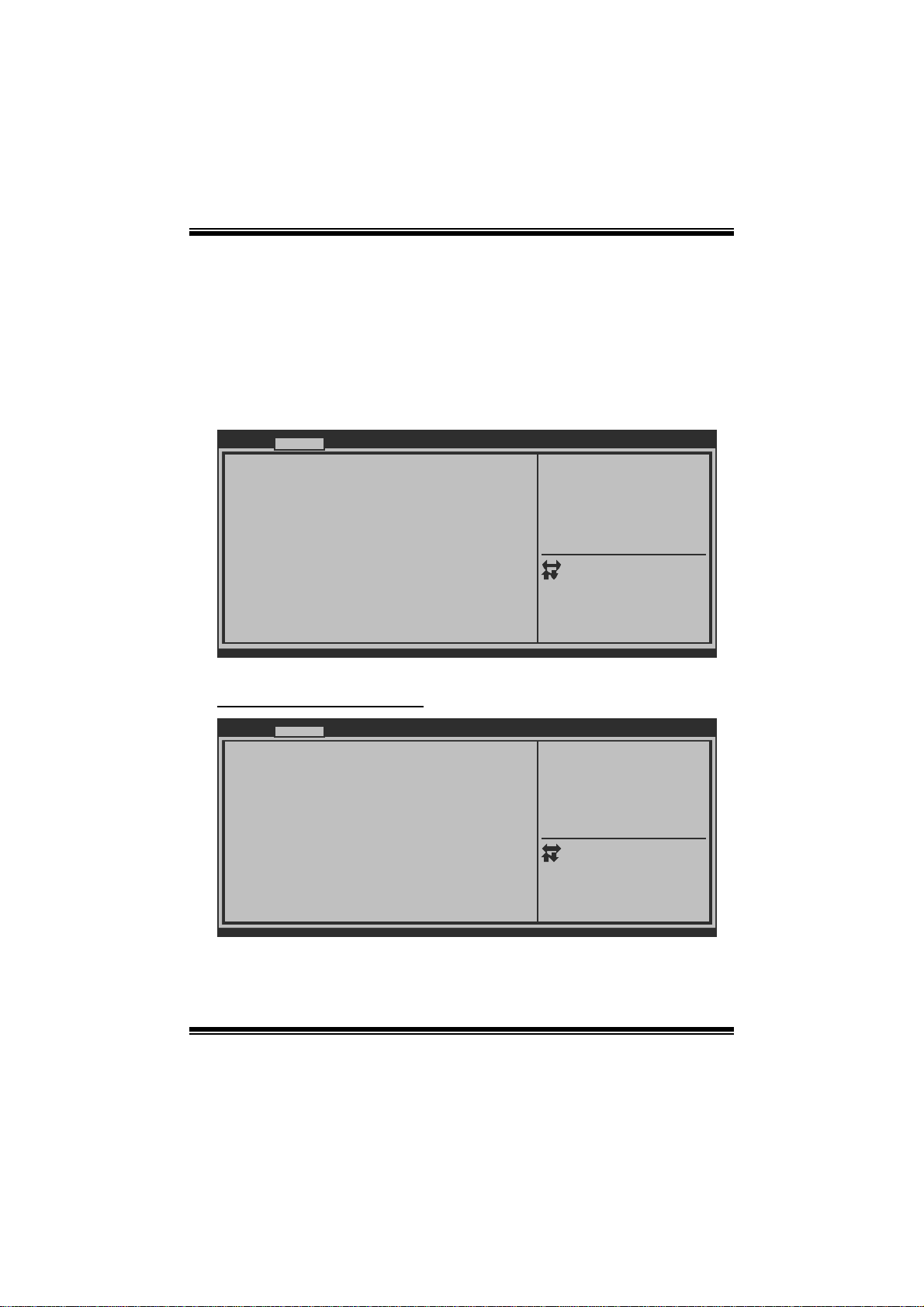
T he Advanced Menu allows you to configure the setti ngs of CP U, Super I/O, P ower
Management, and other system devices.
Notice
z Beware of that setting inappropriate values in items of this menu may cause
system to m alfunction.
Main Advanced Chipset Boot Security O.N.E Save & Exit
> PCI Sub sys tem Setti ngs
> ACPI Settings/WakeUp Event control
> CPU Con fig uration
> SATA Co nfigurati on
> USB Con fig uration
> SMAR T F AN Control
> Super IO Configuration
> H/W Mon ito r
Version x.xx.xxxx. Copyright© 201x, American Megatrends, Inc.
BI OS SET UP UTILITY
PCI, PCI-X and PCI Express
Settings.
Select Screen
Select Item
Enter
Select
+/-
Change Opt.
F1
G ener al Help
F3
Optimized Defaults
F4
S ave & R eset
ESC
Exit
PCI Subsystem Settings
Advanced
PCI Bus Driver Version V x.xx.xx
PCI ROM Priority [Legacy ROM]
PCI Common Settings
PCI Latency Timer [32 PCI Bus Clocks]
VGA Palette Snoop [Disabled]
PCI Express Device Settings
No Snoop [Enabled]
Maximum Payload [Auto]
Maximum Read Request [Auto]
PCI Express Link Settings
ASPM Support [Disabled]
WARNING: Enabling ASPM may cause some
PCI-E devices to fail
Version x.xx.xxxx. Copyright© 201x, American Megatrends, Inc.
BI OS SET UP UTILITY
I n case of mul tiple Opiton
ROMs (Legacy and EFI
Compatible), specifies what
P CI Opti on ROM to launc h.
Select Screen
Select Item
Enter
Select
+/-
Change Opt.
F1
G ener al Help
F3
Optimized Defaults
F4
S ave & Rese t
ESC
Exit
4
Page 6

T H 67+ /TH67 UEFI BIOS Man u al
PCI ROM Priori t y
In case of multiple option ROMs (Legacy and EFI Compatible), this item specifies
what P C I Option R OM to launch
Options: Legacy ROM (De fault) / EFI Compatible ROM
PCI Latency Timer
T his item sets the value to be programmed into PCI Latency Timer Register.
Options: 32 PCI Bus Clocks (Default) / 64 PCI Bus C locks / 96 PCI Bus Clocks /
128 PC I Bus C locks / 160 PCI Bus Clocks / 192 PCI Bus Clocks / 224
PCI Bus Clocks / 248 PCI Bus Clocks
VG A Palette S noop
T his i tem enables or disables VGA Palette Registers Snooping.
Options: Disabled (De fault) / Enabled
No Snoop
T his i tem enables or disables PCI Express Device No Snoop option.
Options: Enabled (Default) / Disabled
Maximu m Paylo ad
T his item sets Maximum Payload of PCI Express Device or allows System BIOS to
sel ect t h e val ue.
Options: Auto (Default) / 128 Bytes / 256 Bytes / 512 Bytes / 1024 Bytes / 2048
Bytes / 4096 Bytes
Maximu m Rea d Requ est
This item sets Maximum Read Request Size of PCI Express Device or allows
System BIO S to se lect th e value.
Options: Disabled (De fault) / Enabled
ASPM Supp ort
This item sets the ASPM Level: Force LO – Force all links to LO State; Auto –
B IOS au t o co nfig u res ; Dis ab l ed – Di s ab les A S PM.
Options: Disabled (De fault) / Auto / Force LO
5
Page 7
T H 67+ /TH67 UEFI BIOS Man u al
AC P I Set t ings/WakeUp Event control
Advanced
EuP Control [Disabled]
ACPI Sleep State [S1 (CPU Stop Clock)]
PME Wake up from S5 [Disabled]
Wake system with Fixed Time [Disabled]
Wake up date [EveryDay]
Wake up hour 0
Wake up minute 0
Wake up second 0
Ring-In Wake up from S5 [Disabled]
PS2 Keyboard PowerOn [Disabled]
Stroke key [Wake Key]
Sp ecif ic key
PS2 Mouse PowerOn [Disabled]
USB Device Wakeup from S3/S4 [Disabled]
Version x.xx.xxxx. Copyright© 201x, American Megatrends, Inc.
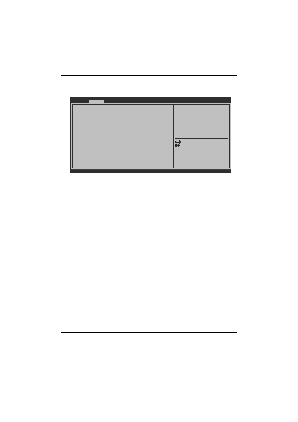
EuP Control
W h en Eu P is enabl ed , the sys t em w i ll m eet EuP requi rem ent .
Options: Disabled (De fault) / Enabled
ACPI Sleep State
BI OS SET UP UTILITY
When EuP Enabled,System meets
E uP requ irement.
Select Screen
Select Item
Select
Enter
+/-
Change Opt.
F1
G ener al Help
F3
Optimized Defaults
F4
S ave & R eset
ESC
Exit
This item selects the highest ACPI sleep state the system will enter when the
SUS PEND button is pressed.
Options: S1 (CPU Stop Clock) (Default) / Suspend Disabled / S3 (Suspend to
RAM)
PME Wake up from S5
Th e it em enables t h e s yst em t o wak e from S5 u s i ng PM E event .
Options: Disabled (De fault) / Enabled
W ak e sy stem wit h Fi xed T i m e
Th i s i t em en ables o r d isab l es t he sy s t em to w ak e o n b y al arm ev ent. Wh en thi s i t em
is enabled, the system will wake on the hr::min::sec specified.
Options: Disabled (De fault) / Enabled
6
Page 8

T H 67+ /TH67 UEFI BIOS Man u al
Wake up date
You can choose which date the syst em will boot up.
Wake up hour / Wake up minute / Wa ke up second
You can choose the system boot up time, input hour, minute and second to specify.
Ring-In Wake up from S5
T his item enables the system to wake from S 5 using Ring-In event.
Options: Disabled (De fault) / Enabled
PS2 Keyboard PowerOn
T his i tem allows you to control the keyboard power on function.
Options: Disabled (De fault) / Any Key / S troke Key / S pecifi c Key
Stroke Keys Selected
T his i tem will show only when Keyboard P owerOn is set “Stroke Key.”
Options: Wake Key (Default) / Power Key / Ctrl+F 1 / C trl+F2 / Ctrl+ F3 /
C t rl +F 4 / Ct rl + F5 / Ct rl +F 6
Specific Key Enter
This item will show only when Keyboard PowerOn is set “Specific Key.” Press
Enter to set Specific key.
PS2 Mou s e PowerO n
T his i tem allows you to control the mouse power on function.
Options: Disabled (De fault) / Enabled
USB Device Wakeup from S3/S4
T his i tem allows you to enable or disabled the USB resume from S3/S4 function.
Options: Disabled (De fault) / Enabled
7
Page 9
T H 67+ /TH67 UEFI BIOS Man u al
CPU Configurati on
Advanced
CPU Configuration
EMT64
Processor Speed
Processor Stepping
Microcode Revision
Processor Cores
In tel HT Tec hnology
Active Processor Cores [All]
Limit CPUID Maximum [Disabled]
Execute-Disable Bit [Enabled]
Hardware Prefetcher [Enabled]
Adjacent Cache Line Prefetch [Enabled]
In tel Vir tualization Tech nology [Disabled]
Power Technology [Energy Efficient]
Local x2APIC [Disabled]
Version x.xx.xxxx. Copyright© 201x, American Megatrends, Inc.
Acti ve Pro c essor C ores
Th i s i t em sets nu mb er of cores to en ab l e in each proces s o r packag e.
Options: All (De fault) / 1 / 2 / 3
Lim it CPUID Maxi mum
When the computer is booted up, the operating system executes the CPUID
instruction to identify the processor and its capabilities. Befo re it can do so, it must
first query the processor to find out the highest input value CPUID recognizes. T his
determines the kind of basic information C PUID can provide the operati ng syst em.
Options: Disabled (De fault) / Enabled
BI OS SET UP UTILITY
Number of cores to enable in
each processor package.
Select Screen
Select Item
Enter
Select
+/-
Change Opt.
F1
G ener al Help
F3
Optimized Defaults
F4
S ave & Rese t
ESC
Exit
E xecute-D i sab le B it
XD can prevent certai n cl as s es o f m al ici ous b uffer ov er flow at t ack s when comb i n ed
with a supporting OS (Windows S erver 2003 SP1, Windows XP SP2, SuSE Linux
9.2, RedHat Enterprise 3 Update 3. ).
Options: Enabled (Default) / Disabled
8
Page 10

T H 67+ /TH67 UEFI BIOS Man u al
Hardware Prefetcher
Th e proces s o r h as a h ard war e pre fet cher th at au t om at i cal l y anal yzes i t s req u irem ents
and pre fet ch es dat a and in s t ru ct ion s fro m t he memo ry i nt o t he L ev el 2 cach e t h at ar e
likely to be required in the near future. This reduces the latency associated with
m emory read s.
Options: Enabled (Default) / Disabled
Adj acent Cache Line Prefetch
The processor has a hardware adjacent cache line prefet ch mechanism that
aut o mat i cal l y fet ch es an ext ra 6 4-by t e cach e l i n e whenev er t he p ro cesso r requests for
a 64-byte cach e line. This reduces cache latency by making the next cache line
immediately available if the processor requir es it as well.
Options: Enabled (Default) / Disabled
Intel Virtualization Te ch
Virtualization Technology can virtually separate your system resou rce into several
parts, thus enhance the performance when running virtual machines or multi
interfa ce systems.
Options: Disabled (De fault) / Enabled
Power Technology
Th is i tem enables the po wer ma nagement f eature s.
Op t i ons : Energ y Effici en t (D efau l t ) / Dis ab l ed / C u sto m
CPU C3 Re port
Th i s it em en ables/ d is ables CP U C3 (ACPI C2) report to O S.
Options: Disabled (Default) / ACPI C -2 / ACP I C-3
CPU C6 Re port
Th i s it em en ables/ d is ables CP U C6 (ACPI C3) report to O S.
Options: Enabled (Default) / Disabled
Package C State Limit
This item sets Package C State Limit.
Options: No Limit (Default) / C0 / C1 / C6 / C7
9
Page 11

T H 67+ /TH67 UEFI BIOS Man u al
Local x2APIC
T his i tem enables Local x2AP IC. Some OS es do not support this featu re.
Options: Disabled (De fault) / Enabled
SATA Configurati on
Advanced
SATA Configuration
SATA Mode [IDE Mode]
Serial-ATA Controller 0 [Compatible]
Serial-ATA Controller 1 [Enhanced]
SATA Port1:
SATA Port2:
SATA Port3:
SATA Port4:
SATA Port5:
SATA Port6:
Version x.xx.xxxx. Copyright© 201x, American Megatrends, Inc.
SATA Mode
This ite m se ts SATA Mod e.
Options: IDE Mode (Default) / AHCI Mode / RAID Mode / Disabled
BI OS SET UP UTILITY
( 1) IDE Mod e. (2) AHCI Mode.
( 3) RAID Mode.
Select Screen
Select Item
Enter
Select
+/-
Change Opt.
F1
G ener al Help
F3
Optimized Defaults
F4
S ave & R eset
ESC
Exit
Se rial-ATA Con troller 0
T his item enables/disables Serial AT A Controller 0.
Options: Compatible (Default) / Disabled / Enhanced
Se rial-ATA Con troller 1
T his item enables/disables Serial AT A Controller 1.
Options: Enhanced (Default) / Disabled
Ag g ressi ve L ink Power Ma nagem ent
Aggressive Link Power M anagement Support.
Options: Enabled (Default) / Disabled
10
Page 12

T H 67+ /TH67 UEFI BIOS Man u al
Spin Up Device
If this item is enabled for any of ports, Staggered Spin Up will be performed, and
only the drives that have this option enabled will spin up at boot. Otherwise, all
drives spi n up at boot.
Options: Disabled (De fault) / Enabled
Hot Plug
SATA P orts Hot P lug Support.
Options: Enabled (Default) / Disabled
USB Configurati on
Advanced
USB Configuration
USB Devices:
Legacy USB Support [Enabled]
EHCI Hand-off [Disabled]
Port 60/64 Emulation [Enabled]
Version x.xx.xxxx. Copyright© 201x, American Megatrends, Inc.
Legacy USB Support
T his item determines if the BIOS should provide legacy support fo r USB devices
li ke the key board, mouse, and USB dri ve. T hi s is a useful fe ature wh en using s uch
USB devices with operating systems that do not natively support USB (e.g.
Microsoft DOS or Windows NT).
Options: Enabled (Default) / Disabled / Auto
EHCI Ha nd-Off
T his i s a workaround for OSes without EHCI hand-off support. The EHCI ownership
change should be claimed by EHC I driver.
Options: Disabled (De fault) / Enabled
BI OS SET UP UTILITY
Enables Legacy USB support.
AUTO opiton disables legacy
s upp ort if no USB devices a re
c onn ected. DISABLE opti on
will keep USB devices
available only for EFI
applications.
Select Screen
Select Item
Select
Enter
+/-
Change Opt.
F1
G ener al Help
F3
Optimized Defaults
F4
S ave & R eset
ESC
Exit
11
Page 13

T H 67+ /TH67 UEFI BIOS Man u al
Port 60/64 Emulation
T his items enables I/O port 60h/64h emulation support. This should be enabled for
the complete US B keyboard legacy support for non-USB aware OSes.
Options: Enabled (Default) / Disabled
SM ART FAN Co nt r ol
Advanced
SMA RT FAN Control
CPU Smart FAN [Disabled]
> CPU FAN Calibrate
Control Mode [Manual]
FAN Ctrl OFF( C)
FAN Ctrl ON(C)
FAN Ctrl Start value
FAN Ctrl Sensitive
o
o
Version x.xx.xxxx. Copyright© 201x, American Megatrends, Inc.
CPU Smart FAN
This ite m allo w s you to contr ol the CPU Smart Fan function.
Options: Disabled (De fault) / Auto
CPU FAN Cal i br ate
Press [ENT ER] to calibrate CPU FAN.
Contr ol Mode
T his i tem provides several oper ation modes of the fan.
Options: Quiet / Aggressive / Manual
Fan Ctrl OFF (℃)
BI OS SET UP UTILITY
C PU FAN Sma rt control
function. [Disabled]: Full ON
[Auto]:By parameters below.
Select Screen
Select Item
Enter
Select
+/-
Change Opt.
F1
G ener al Help
F3
Optimized Defaults
F4
S ave & R eset
ESC
Exit
When C PU temperature is lower than this value, the CPU fan will keep lowest RPM.
Options: 10 (℃) (defaul t )
12
Page 14

T H 67+ /TH67 UEFI BIOS Man u al
Fan Ctrl On(℃ )
When C PU temperature is higher than this value, the CPU fan controller will turn on.
Options: 20 (℃) (Defaul t )
Fan Ctrl S tart Va l ue
This ite m se ts CPU FA N Start S pe ed Va lue.
Options: 50 (Default)
Fan Ctrl Sensitive
T he bigger the numeral is, the higher the F AN speed is.
Options: 30 (Default)
Super IO Configuration
Advanced
Su per IO Con figuration
Su per IO Chi p
Restore AC Power Loss [Power Off]
> Serial Port 0 Configuration
> CIR Controller Configuration
BI OS SET UP UTILITY
Specify what state to go to
w hen power is re-applied
a fte r a power failure.
Select Screen
Select Item
Select
Enter
+/-
Change Opt.
F1
G ener al Help
F3
Optimized Defaults
F4
S ave & R eset
ESC
Exit
Version x.xx.xxxx. Copyright© 201x, American Megatrends, Inc.
Restore AC Power Loss
T his s etting specifies how your system should behave a fte r a power fail or interrupts
occurs. Power Off: Leaving the system in power-off status after power recovers.
P ower ON : P oweri ng on t he system immediatel y when power ret urns . Last S tat e: 1.
Leaving the system in power-off if the system shuts down at DC off status; 2.
Powering on the system immediately if the system shuts down at DC on status.
Options: Power Off (Default) / Power On / Last S tate
13
Page 15
T H 67+ /TH67 UEFI BIOS Man u al
Serial P or t 0 Configuration
Advanced
Serial Port 0 Configuration
Serial Port [Enabled]
Device Settings
Change Settings [Auto]
Version x.xx.xxxx. Copyright© 201x, American Megatrends, Inc.
Serial Port
Th i s it em en abl es o r disab l es Serial P o rt (COM ).
Options: Enabled (Default) / Disabled
Change Settin g s
T his item selects an optimal setting for Super IO device.
Options: Auto (Default)
BI OS SET UP UTILITY
Enable or Disable Serial Port
(COM)
Select Screen
Select Item
Select
Enter
+/-
Change Opt.
F1
G ener al Help
F3
Optimized Defaults
F4
S ave & R eset
ESC
Exit
CIR Controll er Conf iguratio n
Advanced
CIR Controller Configuration
CIR Controller [Disabled]
Version x.xx.xxxx. Copyright© 201x, American Megatrends, Inc.
BI OS SET UP UTILITY
CIR Contro ller
T his item enables or disables CIR Controller.
Options: Disabled (De fault) / Enabled
14
Enable or Disable CIR
Controller
Select Screen
Select Item
Enter
Select
+/-
Change Opt.
F1
G ener al Help
F3
Optimized Defaults
F4
S ave & R eset
ESC
Exit
Page 16
T H 67+ /TH67 UEFI BIOS Man u al
Change Settin g s
T his item selects an optimal setting for Super IO device.
Options: Auto (Default)
H/W Monitor
Advanced
PC Health Status
ShutDown Temperature [Disabled]
CPU temperature :
System temperature :
CPU Fan Speed :
SYS FAN1 Speed :
SYS FAN2 Speed :
CPU Vcore :
DRAM Voltage :
Vcc SA :
IGD Voltage :
Vcc IO :
+12V :
+ 5V :
Version x.xx.xxxx. Copyright© 201x, American Megatrends, Inc.
Shutdown Temperature
T his i tem allows you to set up the C P U shutdown Temperature.
Options: Disabled (De fault) / 70 /158 / 75 /167 / 80 /176 / 85 /185 ℃℉℃℉℃℉ ℃℉
/ 90 /194℃℉
BI OS SET UP UTILITY
ShutDown Temperature
Select Screen
Select Item
Select
Enter
+/-
Change Opt.
F1
G ener al Help
F3
Optimized Defaults
F4
S ave & R eset
ESC
Exit
15
Page 17

T H 67+ /TH67 UEFI BIOS Man u al
3 Chipset Menu
T his section describes configuring the PCI bus system. PCI, or Personal Computer
Interconnect, is a system which allows I/O devices to operate at speeds nearing the
speed of the CPU itself uses when communicating with its own special components.
Notice
z Beware of that setting inappropriate values in items of this menu may cause
syste m to ma lfunc tion .
Main Advanced Chipset Boot Security O.N.E Save & Exit
> Nort h B ridge
> Sou
th Bridge
> Onboard PCI-E Devices
Version x.xx.xxxx. Copyright© 201x, American Megatrends, Inc.
BI OS SET UP UTILITY
No rth Bri dge Param eters
Select Screen
Select Item
Select
Enter
Change Opt.
+/F1
G ener al Help
Optimized Defaults
F3
S ave & R eset
F4
Exit
ESC
16
Page 18

T H 67+ /TH67 UEFI BIOS Man u al
Nort h Bridge
Chipset
Memory Information
To tal Mem ory
DDR3_A1
DDR3_A2
DDR3_B1
DDR3_B2
VT-d [Disabled]
Initate Graphic Adapter [PEG/IGD]
IGD Memory [64M]
Render Standby [Enabled]
IGD Multi-Monitor [Disabled]
DVMT Mode Select [DVMT Mode]
DVMT/FIXED Memory [256MB]
PCI Express Port [Auto]
PEG Force Gen1 [Disabled]
Detect Non-Compliance Device [Enabled]
Version x.xx.xxxx. Copyright© 201x, American Megatrends, Inc.
VT-d
T his item enables/disables VT -d function.
Options: Disabled (De fault) / Enabled
Initiate G raphic Adapter
BI OS SET UP UTILITY
VT-d Enable/Disable
Select Screen
Select Item
Select
Enter
Change Opt.
+/F1
G ener al Help
Optimized Defaults
F3
S ave & R eset
F4
Exit
ESC
T his item allows you to select which graphics controller to use as the primary boot
device.
Options: PEG/PCI (Default) / IGD / PCI/IGD / PCI/P EG / PEG/IGD
IGD Memory
T his item sets IGD Share Memory Size.
Options: 64M (De fault) / Disabled / 32M / 128M
Render Sta ndby
Th i s i t em en ables / d i s ables R en der S t an d by by Int ernal Graphi cs D evic e.
Options: Enabled (Default) / Disabled
IGD Multi- Mo nit or
T his item enables/disables IGD Multi-Monitor by Internal Graphics Device.
Options: Disabled (De fault) / Enabled
17
Page 19

T H 67+ /TH67 UEFI BIOS Man u al
DVMT M ode Select
T his i tem selects DVMT Mode used by Internal Graphics Device.
Options: DVM T M ode (Default) / F ixed Mode
DVMT/FIXED Memory Size
DVMT stands for “ Dynamic Video Memory T echnology”. T his is an enhancement
of the unified memory architecture (UMA) concept. DVMT will set the optimum
amount of memory to be allocated for a balance between graphics and system
perform ance. DVMT dynamically respond to system requirements and applications
demands, by allocating the proper amount of display, texturing and buffer memory
after the oper ating system has booted.
Options: 256MB (Default) / 128MB / Maximum
PCI Express Po rt
T his i tem allows user to control P C I Express x16 Port.
Options: Auto (Default) / Disabled / Enabled
PEG Force GEN1
Some non-graphics PCI-E devices may not follow PCI-E Specification and may
incorre ctly report their Gen capability or link width.
Options: Disabled (De fault) / Enabled
Detect Non-Compliance Device
Detect Non-Compli ance PC I Express Device in PEG.
Options: Enabled (Default) / Disabled
18
Page 20

T H 67+ /TH67 UEFI BIOS Man u al
South Br idge C onfigura tion
Chipset
ME Version
SB Chipset Configuration
SMBus Controller [Enabled]
Au dio Con figuration
Azalia HD Audio [Enabled]
Azalia internal HDMI codec [Enabled]
Hi gh P recision Eve nt Timer Configu ration
High Precision Timer [Enabled]
USB Configuration
All USB 1.0/2.0 Devices [Enabled]
EHCI Controller 1 [Enabled]
EHCI Controller 2 [Enabled]
Version x.xx.xxxx. Copyright© 201x, American Megatrends, Inc.
SMBus Controller
T his item enables/disables SMBus Controller.
Options: Enabled (Default) / Disabled
Aza lia HD Audio
T his item enables/disables Azalia HD Audio.
Options: Enabled (Default) / Disabled
Azal ia int ern al HDMI codec
T his item enables/disables internal HDMI codec for Azalia.
Options: Enabled (Default) / Disabled
BI OS SET UP UTILITY
Enabled/Disabled SMBus
Controller.
Select Screen
Select Item
Select
Enter
Change Opt.
+/F1
G ener al Help
Optimized Defaults
F3
S ave & R eset
F4
Exit
ESC
High P recision Timer
T his item enables/disables the High P recision Event T imer.
Options: Enabled (Default) / Disabled
All USB 1.0/2.0 Devices
T his i tem enables/disables All US B 1.0/2. 0 Devices.
Options: Enabled (Default) / Disabled
19
Page 21

T H 67+ /TH67 UEFI BIOS Man u al
EHCI Controller 1
T his i tem enables/disables USB 2.0 (EHCI) Support.
Options: Enabled (Default) / Disabled
EHCI Controller 2
T his i tem enables/disables USB 2.0 (EHCI) Support.
Options: Enabled (Default) / Disabled
Onboard PC I-E Devices
Chipset
Onboard PCI-E Devices
LA N0 M AC ID =
Legacy OpROM Support
Launch PXE OpROM [Disabled]
Launch Storage OpROM [Enabled]
Onboard PCIE Giga LAN [Auto]
Onboard USB3.0 [Auto]
Onboard PCI Bridge [Auto]
Version x.xx.xxxx. Copyright© 201x, American Megatrends, Inc.
BI OS SET UP UTILITY
Enable or Disable Boot Option
for Legacy Network Devices.
Select Screen
Select Item
Select
Enter
Change Opt.
+/F1
G ener al Help
Optimized Defaults
F3
S ave & R eset
F4
Exit
ESC
Launch PXE OpROM
T his item enables/disables Boot Option for Legacy Network D evices.
Options: Disabled (De fault) / Enabled
Launch Storage OpROM
This item enables/disables Boot Option for Legacy Mass Storage Devices with
Option ROM.
Options: Enabled (Default) / Disabled
Onboard PCIE G iga LAN
T his i tem enables/disables Onboard P CIE Giga LAN.
Options: Auto (Default) / Disabled / Enabled
20
Page 22

T H 67+ /TH67 UEFI BIOS Man u al
Onboard USB3 .0
T his item enables/disables Onboard USB3.0.
Options: Auto (Default) / Disabled / Enabled
Onboard PCI Bridge
T his i tem enables/disables Onboard P CI Bridge.
Options: Auto (Default) / Disabled / Enabled
21
Page 23
T H 67+ /TH67 UEFI BIOS Man u al
4 Boot Menu
T his m enu allows you to setup the system boot options.
Main Advanced Chipset Boot Security O.N.E Save & Exit
Boot Configuration
Setup Prompt Timeout 1
Bootup NumLock State [On]
Full Logo Screen display [Enabled]
CS M16 Mod ule Versi on
GateA20 Active [Upon Request]
Interrupt 19 Capture [Disabled]
Boot Option Priorities
Boot Option #1
Boot Option #2
Boot Option #3
CD/DVD ROM Drive BBS Priorities
Hard Drive BBS Priorities
Version x.xx.xxxx. Copyright© 201x, American Megatrends, Inc.
Setup Prompt Timeout
T his item sets number of seconds to wait for setup activation key.
Options: 1 (Default)
BI OS SET UP UTILITY
Number of seconds to wait for
se tup act ivation key.
Enter
+/-
F1
F3
F4
ESC
Select Screen
Select Item
Select
Change Opt.
G ener al Help
Optimized Defaults
S ave & R eset
Exit
Boot up Num L ock St at e
T his i tem selects the keyboard NumLock state.
Options: On (Default) / Off
Full Screen LOGO Disp lay
T his i tem allows you to enable/disable Full Screen LOGO Show function.
Options: Enabled (Default) / Disabled
GateA 20 Active
Upon Request – FA20 can be disabled using BIOS services. Always – do not allow
disabling GA20; this option is us eful when any RT code is executed above 1MB
Options: Upon Request (Defaul t) / Always
22
Page 24

T H 67+ /TH67 UEFI BIOS Man u al
Interrupt 19 Capture
Interrupt 19 is the software interrupt that handles the boot disk function. When set
to Enabled, this item allows the option ROMs to trap interrupt 19.
Options: Disabled (De fault) / Enabled
Boot Option #1/#2/#3
T he 3 items specify the boot device prio rity sequence from the available devices.
T he number of device items that appears on the screen depends on the number o f
devices installed in the system.
CD /DV D RO M Dri ve BBS P r ior it ie s
T his i tem sets the order of the legacy devic es in this group.
Hard Drive BBS Priorities
T his i tem sets the order of the legacy devic es in this group.
23
Page 25
T H 67+ /TH67 UEFI BIOS Man u al
5 Security Menu
Main Advanced Chipset Boot Security O.N.E Save & Exit
Pa sswo rd Description
If ONL Y the Administr ator’s password is set,
then this only limits access to Setup and is
only asked for when entering Setup.
If ONLY the User’s password is set, then this
is a power on password and must be entered to
boot or enter Setup. In Setup the User will
have Administrator rights.
The password must be 3 to 20 characters long.
Administrator Password
User Password
Version x.xx.xxxx. Copyright© 201x, American Megatrends, Inc.
BI OS SET UP UTILITY
Set Setup Administrator
Password
Enter
+/F1
F3
F4
ESC
Admi nistrator Pass wo rd
This ite m se ts A dministra tor Pa sswo r d.
Use r P assword
This ite m se ts U se r Passwor d .
Select Screen
Select Item
Select
Change Opt.
G ener al Help
Optimized Defaults
S ave & R eset
Exit
24
Page 26
T H 67+ /TH67 UEFI BIOS Man u al
6 O.N.E Menu
T his s ubmenu allows you to change voltage and clock of various devi ces.
(However, we suggest you use the default setting. Changing the voltage and clock
improperly may damage the device.)
Notice
z Beware of that setting inappropriate values in items of this menu may cause
system to m alfunction.
Main Advanced Chipset Boot Security O.N.E Save & Exit
Notice: Please Clear CMOS if system no display
after overclocking
Start Page [Page - Main]
====Manual CPU system====
Fixed CPU Ratio [Disabled]
CPU Ratio 31
CPU Core Current Max(Amp) 150
Power Limit 1 Value (Watt) 95
Power Limit 2 Switch [Enabled]
Power Limit 2 Value 118
En hanc ed Intel SpeedStep Tech [Enabled]
Turbo Mode [Enabled]
CPU CIE [Enabled]
Graphics Core Ratio Limit 22
CPU Clock 100
Spread Spectrum [Auto]
Version x.xx.xxxx. Copyright© 201x, American Megatrends, Inc.
BI OS SET UP UTILITY
You can set the entrance Page
wh en y ou enter UEFI BIOS
Setup
Select Screen
Select Item
Select
Enter
Change Opt.
+/F1
G ener al Help
Optimized Defaults
F3
S ave & R eset
F4
Exit
ESC
Start Page
You can set the entrance page when you enter UEFI BIOS S etup.
Options: P age – Main (De fault) / Page – Advanced / P age – Chipset / Page – Boot
/ Page – Security / Page – O.N. E / Page – Save & Exit
Fixed CPU Ratio
T his item enables/disables Fixed CP U Ratio all the time.
Options: Disabled (De fault) / Enabled
CPU Ratio
T his item allows you to set the CP U ratio. This item is adjustable only when Fixed
CPU Ratio is set to Enabled.
Options: 31 (Default) / 10 ~ 50
25
Page 27

T H 67+ /TH67 UEFI BIOS Man u al
CPU Core Current Max (Amp)
T his item sets the Max instantaneous current allowed at any given time.
Options: 150 (Default)
Power Limit 1 Value (Watt)
This item sets the power limit value which CPU must not exceed over a specific
time.
Options: 95 (Default)
Power Limi t 2 Switch
T his item enables/disables Power Limit 2 Switch.
Options: Enabled (Default) / Disabled
Power Limi t 2 Value
T his i tem sets P ower Lim it Val ue whi ch C PU must not exceed in a sho rt durat ion
time.
Options: 118 (Default)
Enhanced Intel Sp eedStep Technology
T his i tem enables/di sables Enhanced Intel SpeedStep T echnol ogy.
Options: Enabled (Default) / Disabled
Turbo M ode
This ite m en a bles/disables Turbo Mode .
Options: Enabled (Default) / Disabled
CPU C1 E
C1E is “Enhanced Halt State” function, this function helps to save power and
decr ease he at by lowering C P U frequen cy while the process or is not working.
Options: Enabled (Default) / Disabled
Gra phi c s Co re Rat io Limi t
T his item sets Graphics Core Ratio Limit.
Options: 22 (Default)
26
Page 28

T H 67+ /TH67 UEFI BIOS Man u al
CPU Clock
This ite m se ts CPU Clock.
Options: 100 (Default)
Sp read Spectrum
T his i tem allows you to control S pread Spectrum function.
Options: Auto (De faul t) / Disabled / +/- 0. 20 / +/- 0.25 / +/- 0.375 / +/- 0.50
DDR3 DR AM M ulti plie r
T his i tem allows you to set DDR3 DRAM Multiplier.
Options: Auto (Default) / 10.67 / 13.33
DRA M Timing Control
T his item allows you to choose to manually or automatically regul ate the DRAM
Timing.
Options: By SPD (Default) / Manual / XMP P rofile 1 / XMP Profile 2
DR AM Comman d Rat e
T his i tem allows you to select com mand rate of DDR3.
Options: Auto (Default) / 1T / 2T
CAS# La t ency (tCL)
T his i tem allows you to select CAS Latency of DDR3.
Options: 7 (De fault) / 3 ~ 15
Row Precharge Time ( tRP)
T his i tem allows you to select Row P recharge T ime of DDR3.
Options: 7 (De fault) / 3 ~ 15
RAS# t o CAS# Delay (tRCD)
T his i tem allows you to select Row Address to Column Address Delay of DDR3.
Options: 7 (De fault) / 3 ~ 15
27
Page 29

T H 67+ /TH67 UEFI BIOS Man u al
RAS# Activ e Time (tRAS)
T his i tem allows you to select Row Active T im e of DDR3.
Options: 20 (De fault) / 9 ~ 63
Write Recovery Time (tWR)
T his i tem allows you to select Int ernal Write to Read C ommand Delay of DDR 3.
Options: 8 (De fault) / 3 ~ 31
Row Refresh Cycle Time (tRFC)
T his i tem allows you to select Minimum R efr esh Recovery T im e of DDR 3.
Options: 59 (De fault) / 15 ~ 255
Write to Read De lay (tWTR )
T his i tem allows you to select Int ernal Write to Read Com mand Delay of DDR3.
Options: 4 (De fault) / 3 ~ 31
Active to A ctive Delay (tRRD)
T his i tem allows you to select Row Active to Row Active Delay of DDR3.
Options: 4 (De fault) / 4 ~ 15
Rea d CA S# Precharge (tRTP)
T his i tem allows you to select Read to Precharge Delay of DDR3.
Options: 4 (De fault) / 4 ~ 15
Four Activ e Wind ow Delay (tFAW)
T his i tem allows you to select Four Active Window Delay of DDR3.
Options: 16 (De fault) / 4 ~ 63
CPU Request VCore
T his item sets CP U Request Voltage.
CPU VCore Mode
T his item sets the mode of C PU over voltage.
Options: SPEC Voltage (Default) / Auto / Offset Mode / F ixed Mode
28
Page 30

T H 67+ /TH67 UEFI BIOS Man u al
CPU VCore Offset
T his item sets CP U Vcore Offset Voltage.
CPU VCo re Fi xed
T his item sets CP U Vcore Fixed Voltage.
IG D VCore Mode
T his item sets the mode of the IGD cor e power supply.
Options: SPEC Voltage (Default) / Auto / Offset Mode / F ixed Mode
IGD VCore Offset
T his item sets IGD Vcore Offset Voltage.
IGD VCo re Fixed
T his item sets IGD Vcore Fixed Voltage.
Ph ase Control
T his item sets PWM Phase C ontrol method.
Options: CPU Power State (De fault) / Full On
PWM W ork Frequency
This ite m se ts PWM Work Freque nc y .
Options: Auto (De faul t) / 200 KHz / 185 KHz / 165 KHz / 145 KHz
PW M I-OUT Overrid e
T his item enables/disables PWM I-OUT Override.
Options: Disabled (De fault) / Enabled
PWM Thermal report O v erride
T his item enables/disables PWM Thermal Override.
Options: Disabled (De fault) / Enabled
29
Page 31

T H 67+ /TH67 UEFI BIOS Man u al
VCore LoadLine
This ite m se ts V Cor e L oadLine.
Options: Enabled (Default) / Disabled / 87.5% LoadLine / 75.0% LoadLine /
62.5% LoadLine / 50.0% LoadLi ne / 37.5% LoadLin e / 25.0% LoadLine
/ 12. 5% LoadLin e
CPU PLL
T his i tem sets CPU PLL power suppl y.
DRA M Voltage
This ite m se ts D RAM V oltage .
Vcc SA
T his i tem s ets CPU Sys tem Agent (memory contro ller, DMI, PC Ie co ntro llers, and
display engine) power supply.
PCH Voltage
This ite m se ts PCH Volta ge.
Vcc I O
T his i tem sets CPU High frequency I/O logic power supply.
30
Page 32
T H 67+ /TH67 UEFI BIOS Man u al
DDR3 Slot 1/2/3/ 4 Information
T hese items display SPD information of DDR3 memory.
DDR3 Module Information
Memory Type
Memory Manufacturer
Part Number
Memory Ext.
DRAM Speed
DRAM Voltage
DRAM tCL
DRAM tRCD
DRAM tRP
DRAM tRAS
DRAM tRFC
DRAM tWR
DRAM tWTR
DRAM tRRD
DRAM tRTP
Version x.xx.xxxx. Copyright© 201x, American Megatrends, Inc.
BI OS SET UP UTILITY
O.N.E
Select Screen
Select Item
Select
Enter
Change Opt.
+/F1
G ener al Help
Optimized Defaults
F3
S ave & R eset
F4
Exit
ESC
31
Page 33
T H 67+ /TH67 UEFI BIOS Man u al
7 Exit Menu
This menu allows you to load the optimal default settings, and save or discard the
changes to the BIOS items.
Main Advanced Chipset Boot Security O.N.E Save & Exit
Discard Changes and Exit
Save Changes and Reset
Restore Defaults
Boot Override
Bu ilt- in EFI Shell
Version x.xx.xxxx. Copyright© 201x, American Megatrends, Inc.
Discard Changes and Exit
BI OS SET UP UTILITY
Ex it s ystem setup wit hout
saving any changes.
Select Screen
Select Item
Select
Enter
Change Opt.
+/-
G ener al Help
F1
Optimized Defaults
F3
S ave & R eset
F4
ESC
Exit
Abandon all changes made during the current session and exit setup.
Save Changes and Reset
R es et th e s y s tem after savi n g th e chang es.
Restore Defaults
This selection allows you to reload the BIOS when problem occurs during system
booting sequence. These configurations are factory settings optimized for this
system .
Built-in EFI Shell
Press enter to execute UEFI BIOS built-in EFI Shell..
32
 Loading...