

Page 1

TForce4 AM2 Setup Manual
FCC Information and Copyright
This equipment has been tested and found to comply with the limits of a Class
B digital device, pursuant to Part 15 of the FCC Rules. These limits are designed
to provide reasonable protection against harmful interference in a residential
installation. This equipment generates, uses and can radiate radio frequency
energy and, if not installed and used in accordance with the instructions, may
cause harmful interference to radio communications. There is no guarantee
that interference will not occur in a particular installation.
The vendor makes no representations or warranties with respect to the
contents here and specially disclaims any implied warranties of merchantability
or fitness for any purpose. Further the vendor reserves the right to revise this
publication and to make changes to the contents here without obligation to
notify any party beforehand.
Duplication of this publication, in part or in whole, is not allowed without first
obtaining the vendor’s approval in writing.
The content of this user’s manual is subject to be changed without notice and
we will not be responsible for any mistakes found in this user’s manual. All the
brand and product names are trademarks of their respective companies.
Page 2

Table of Contents
Chapter 1: Introduction.......................................... 1
1.1 Before You Start ................................................................................1
1.2 Package Checklist.............................................................................1
1.3 Motherboard Features......................................................................2
1.4 Rear Panel Connectors .....................................................................3
1.5 Motherboard Layout ........................................................................4
Chapter 2: Hardware Installation............................ 5
2.1 Installing Central Processing Unit (CPU)......................................5
2.2 FAN Headers......................................................................................7
2.3 Installing System Memory................................................................8
Connectors and Slots............................................................................................10
Chapter 3: Headers & Jumpers Setup.................... 12
3.1 How to Setup Jumpers ....................................................................12
3.2 Detail Settings..................................................................................12
Chapter 4: NVIDIA RAID Functions ...................... 20
4.1 Operation System............................................................................20
4.2 Raid Arrays ......................................................................................20
4.3 How RAID Works.............................................................................20
5.1: T-Power Introduction .....................................................................23
5.2: T-Power BIOS Feature....................................................................24
5.3 T-Power Windows Feature ............................................................32
Chapter 6: Useful Help .......................................... 41
6.1 Driver Installation Note .................................................................41
6.2 Award BIOS Beep Code ..................................................................42
6.3 Extra Information ...........................................................................42
6.4 Troubleshooting...............................................................................44
Appendencies: SPEC In Other Language............... 46
German .................................................................................................................46
France....................................................................................................................48
Italian....................................................................................................................50
Spanish ..................................................................................................................52
Portuguese............................................................................................................54
Polish .....................................................................................................................56
RUSSIAN ................................................................................................................58
ARABIC..................................................................................................................60
JAPANESE .............................................................................................................62
Page 3

TForce4 AM2
1
CHAPTER 1: INTRODUCTION
1.1 B
EFORE YOU START
Thank you for choosing our product. Before you start installing the
motherboard, please make sure you follow the instructions below:
Prepare a dry and stable working environment with
sufficient lighting.
Always disconnect the computer from power outlet
before operation.
Before you take the motherboard out from anti-static
bag, ground yourself properly by touching any safely
grounded appliance, or use grounded wrist strap to
remove the static charge.
Avoid touching the components on motherboard or the
rear side of the board unless necessary. Hold the board
on the edge, do not try to bend or flex the board.
Do not leave any unfastened small parts inside the
case after installation. Loose parts will cause short
circuits which may damage the equipment.
Keep the computer from dangerous area, such as heat
source, humid air and water.
1.2 PACKAGE CHECKLIST
FDD Cable X 1
HDD Cable X 1
Serial ATA Cable X 1
Serial ATA Power Cable X 1
Rear I/O Panel for ATX Case X 1
User’s Manual X 1
Fully Setup Driver CD X 1
USB 2.0 Cable X1 (optional)
S/PDIF out Cable X 1 (optional)
Page 4
Motherboard Manual
2
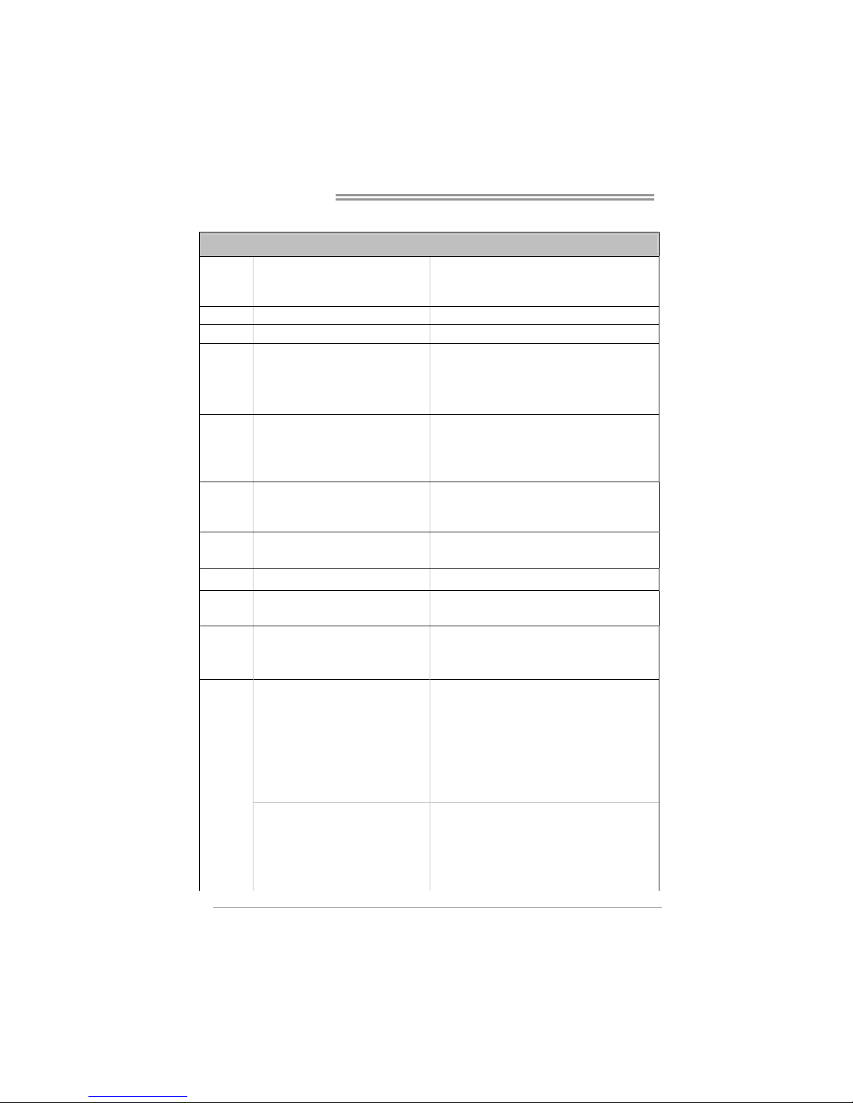
1.3 MOTHERBOARD FEATURES
SPEC
CPU
Socket AM2
AMD Athlon 64 / Athlon 64 FX / Althlon
64X2 / Sempron processors
AMD 64 Architecture enables 32 and 64 bit computing
Supports Hyper Transport and Cool=n=Quiet
FSB Support HyperTransport Supports up to 1000 MHz Bandwidth
Chipset
nVIDIA nForce4
Super I/O
ITE 8712F
Provides the most commonly used legacy
Super I/O functionality.
Low Pin Count Interface
Environment Control initiatives,
H/W Monitor
Fan Speed Controller
ITE's "Smart Guardian" function
Main
Memory
DIMM Slots x 4
Each DIMM supports 256/512MB & 1GB
DDR2
Max Memory Capicity 4GB
Dual Channel Mode DDR2 memory module
Supports DDR2 400 / 533 / 667 / 800
Registered DIMM and Non-ECC DIMM is not supported
IDE
Integrated IDE Controller
Ultra DMA 33 / 66 / 100 / 133 Bus Master
Mode
supports PIO Mode 0~4,
SATA
Integrated Serial ATA Controller
Data transfer rates up to 1.5 Gb/s.
SATA Version 1.0 specification compliant.
LAN Realtek 8201CL PHY 10 / 100 Mb/s Auto-Negotiation
Sound ALC 655 / 658 (optional)
6 channels audio out
AC 97 Version 2.3
PCI slot x4 Supports PCI expansion cards
PCI Express x16 slot x1 Supports PCI Express x16 expansion cards
Slots
PCI Express x 1 slot x2 Supports PCI Express x1 expansion cards
Floppy connector x1 Each connector supports 2 Floppy drives
Printer Port connector x1 Each connector supports 1 Printer port
IDE Connector x2 Each connector supports 2 IDE device
SATA Connector x4 Each connector supports 1 SATA devices
Front Panel Connector x1 Supports front panel facilities
Front Audio Connector x1 Supports front panel audio function
CD-in Connector x1 Supports CD audio-in function
S/PDIF out connector x1 Supports digital audio out function
CPU Fan header x1 CPU Fan power supply (with Smart Fan function)
System Fan header x3 System Fan Power supply
Chassis open header (optional) x1 For chassis intruder detection function
On Board
Connector
CMOS clear header x1 Restore CMOS data to factory default
Page 5

TForce4 AM2
3
SPEC
USB connector x3 Each connector supports 2 front panel USB ports
Power Connector (24pin) x1 Connects to Power supply
Power Connector (4pin) x1 Connects to Power supply
Back Panel
I/O
PS/2 Keyboard x1
PS/2 Mouse x1
Serial Port x1
LAN port x1
USB Port x4
Audio Jack x3
Connects to PS/2 Keyboard
Connects to PS/2 Mouse
Provide RS-232 Serial connection
Connects to RJ-45 ethernet cable
Connects to USB devices
Provide Audio-In/Out and microphone connection
Board Size 218 x 293 (mm)
Special
Features
NVIDIA nTunes
RAID 0 / 1 / 0+1 support
OS Support Windows 2K / XP
Biostar Reserves the right to add or remove support for
any OS With or without notice.
1.4 REAR PANEL CONNECTORS
Line In
Line Out
Mic In
PS/2
Mouse
PS/2
Keyboard
COM1 COM2
(optional)
USBX2USBX2
LAN
Page 6

Motherboard Manual
4
1.5 MOTHERBOARD LAYOUT
JKBMS1
JUSB4
JAUDIO1
JUSBLAN1
BIOS
PCI-EX1_1
PCI1
FDD1
BAT1
JCOM1
JUSBV2
JCDIN1
Codec
LAN
JAUDIO1
JATXPWR2
JPRNT1
PCI2
Super I/O
JUSBV1
JUSB2
JUSB3
DDR2A1
JSFAN1
JCMOS1
JPANEL1
IDE1
JATXPWR1
JCFAN1
JSATA4JSATA3
JSFAN2
JNFAN1
JDDRII_2.3V
LED_D1
LED_D2
DDR2B1
DDR2B2
DDR2A2
JKBMSV1
PCI-EX16
PCI-EX1_2
PCI4
PCI3
nVIDIA
nForce4
JSATA2JSATA1
JCOM2
IDE2
JUSB4
JSPDIF_OUT1
RSTSW2 PWRSW1
(optional)
Note: represents the 1■
st
pin.
Page 7
TForce4 AM2
5
CHAPTER 2: HARDWARE INSTALLATION
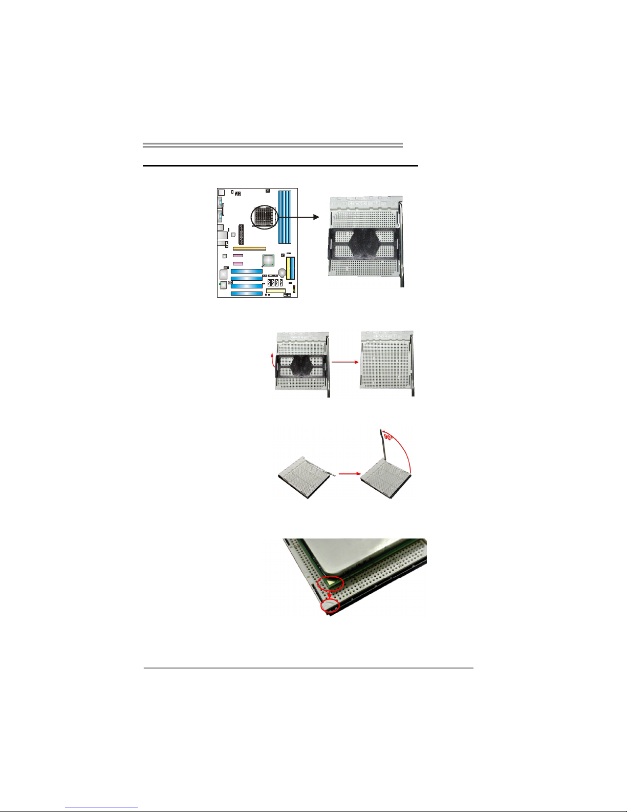
2.1 INSTALLING CENTRAL PROCESSING UNIT (CPU)
Step 1: Remove the socket protection cap.
Step 2: Pull the lever toward direction A from the socket and then raise the
lever up to a 90-degree angle.
Step 3: Look for the white triangle on socket, and the gold triangle on
CPU should point towards this white triangle. The CPU will fit only
in the correct orientation.
Page 8
Motherboard Manual
6
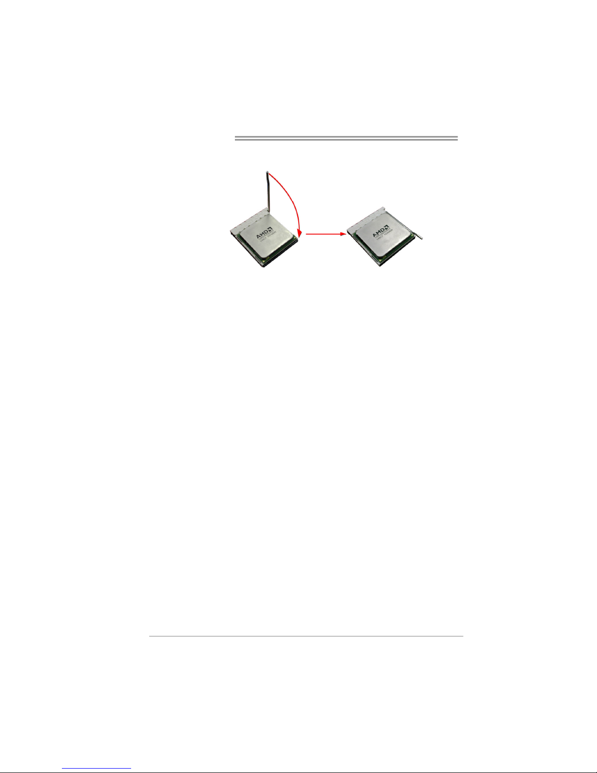
Step 4: Hold the CPU down firmly, and then close the lever toward direct
B to complete the installation.
Step 5: Put the CPU Fan on the CPU and buckle it. Connect the CPU
FAN power cable to the JCFAN1. This completes the installation.
Page 9
TForce4 AM2
7
2.2 FAN HEADERS
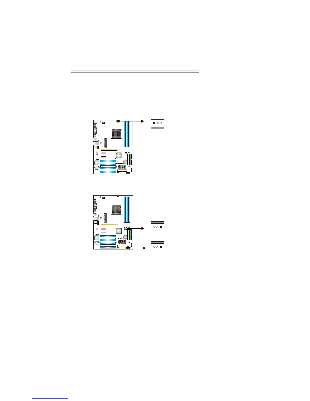
These fan headers support cooling-fans built in the computer. The fan
cable and connector may be different according to the fan manufacturer.
Connect the fan cable to the connector while matching the black wire to
pin#1.
JCFAN1: CPU Fan Header
Pin
Assignment
1 Ground
2 Smart Fan
Control
13
JCFAN1
3 FAN RPM rate
sense
JSFAN1/ JSFAN2: System Fan Header
JNFAN1: North Bridge Fan Header
Pin
Assignment
1 Ground
2 +12V
1133
JNFAN1
JSFAN2
JSFAN1
3 FAN RPM rate
sense
Note:
The JCFAN1、JSFAN1/JSFAN2 and JNFAN1 support 3-pin head connector. When
connecting with wires onto connectors, please note that the red wire is the positive and
should be connected to pin#2, and the black wire is Ground and should be connected to
GND.
Page 10
Motherboard Manual
8
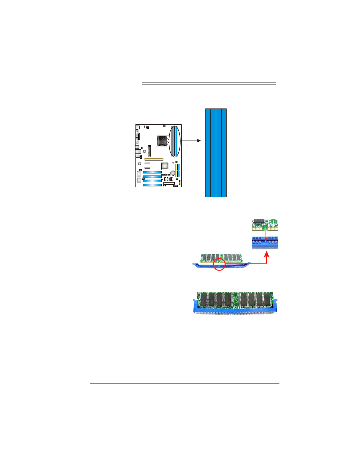
2.3 INSTALLING SYSTEM MEMORY
A. Memory Modules
DDR2A1
DDR2B1
DDR2A2
DDR2B2
1. Unlock a DIMM slot by pressing the retaining clips outward. Align a
DIMM on the slot such that the notch on the DIMM matches the
break on the Slot.
2. Insert the DIMM vertically and firmly into the slot until the retaining
chip snap back in place and the DIMM is properly seated.
Page 11
TForce4 AM2
9
B. Memory Capacity
DIMM Socket
Location
DDR Module
Total Memory
Size
DDR2A1 256MB/512MB/1024MB
DDR2B1 256MB/512MB/1024MB
DDR2A2 256MB/512MB/1024MB
DDR2B2 256MB/512MB/1024MB
Max is 4GB.
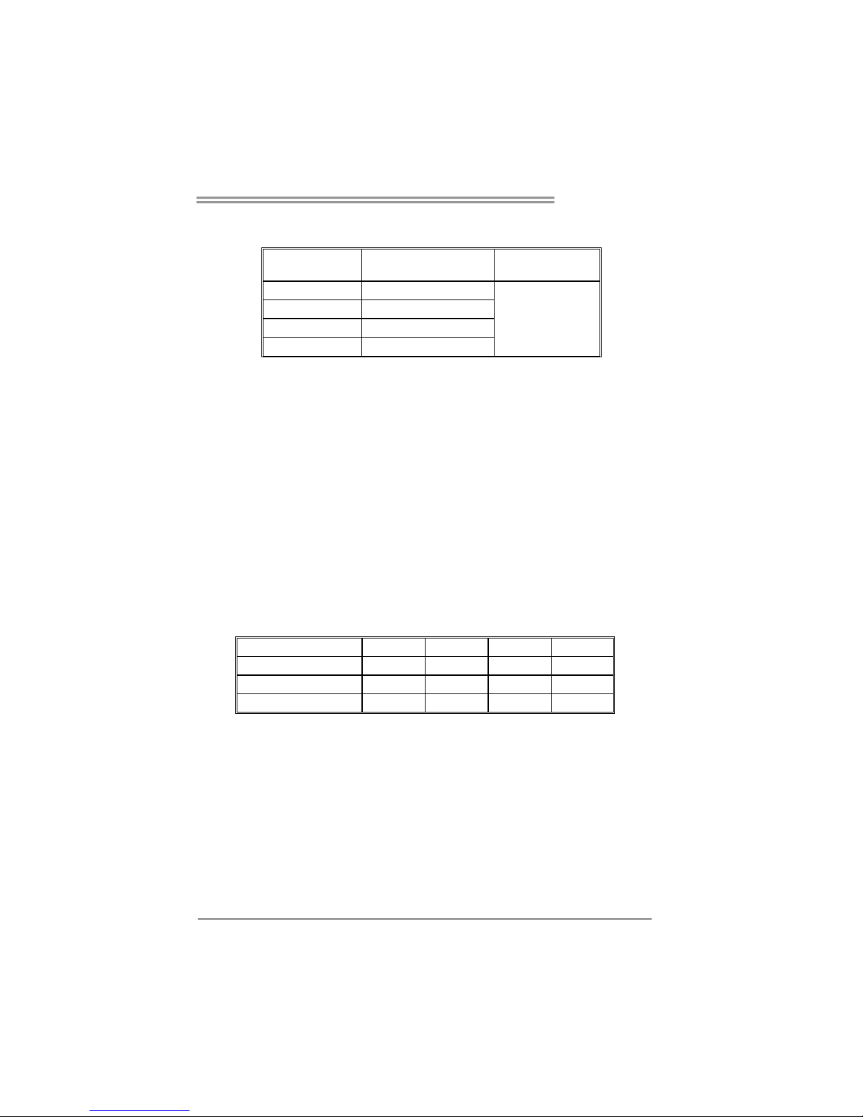
C. Dual Channel Memory installation
To trigger the Dual Channel function of the motherboard, the memory module
must meet the following requirements:
Install memory module of the same density in pairs, shown in the following
table.
Dual Channel Status
DDR2A1
DDR2B1 DDR2A2 DDR2B2
Enabled O O X X
Enabled X X O O
Enabled O O O O
(O means memory installed, X means memory not installed.)
The DRAM bus width of the memory module must be the same (x8 or
x16)
Page 12
Motherboard Manual
10
CONNECTORS AND SLOTS
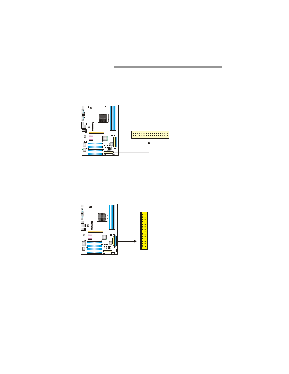
FDD1: Floppy Disk Connector
The motherboard provides a standard floppy disk connector that supports 360K,
720K, 1.2M, 1.44M and 2.88M floppy disk types. This connector supports the
provided floppy drive ribbon cables.
3
4
1
2
33
IDE1/IDE2: Hard Disk Connectors
The motherboard has a 32-bit Enhanced PCI IDE Controller that provides PIO
Mode 0~4, Bus Master, and Ultra DMA 33/66/100/133 functionality. It has two
HDD connectors IDE1 (primary) and IDE2 (secondary).
The IDE connectors can connect a master and a slave drive, so you can
connect up to four hard disk drives. The first hard drive should always be
connected to IDE1.
21
3940
IDE2
IDE1
Page 13
TForce4 AM2
11
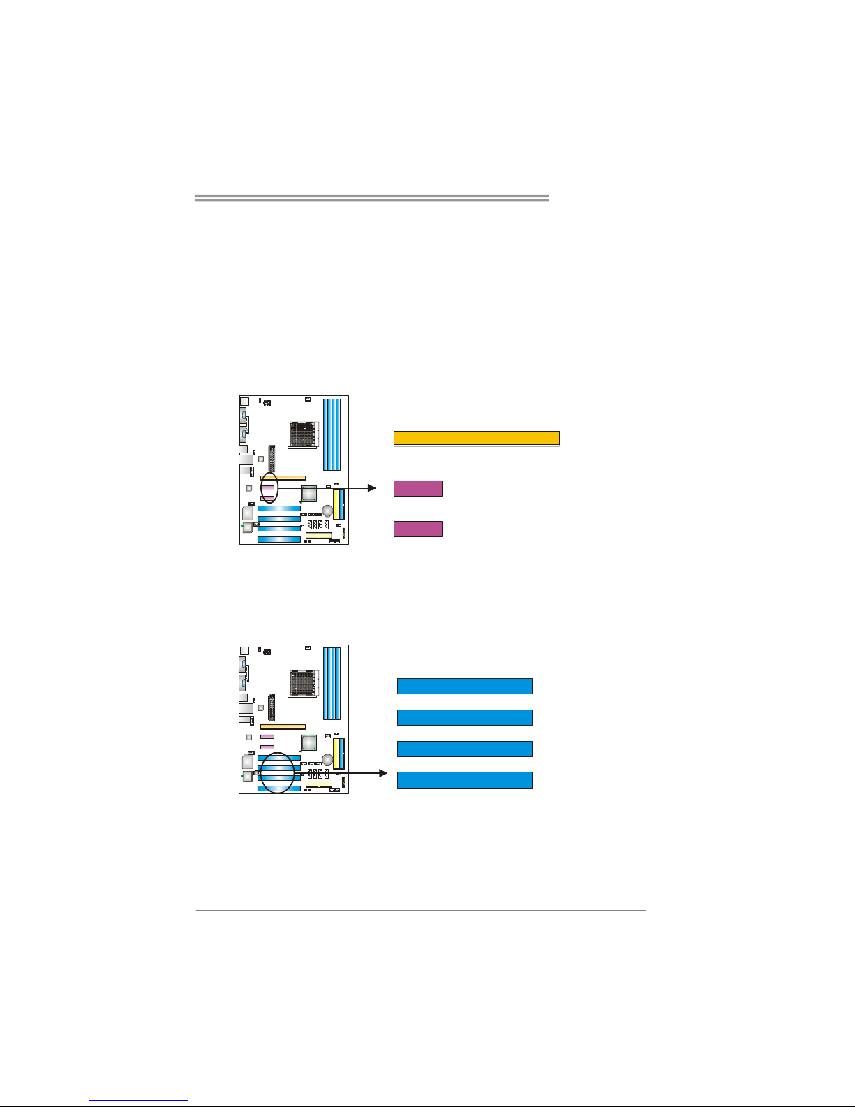
PCI-Ex16: PCI-Express x16 Slot
- PCI-Express 1.0a compliant.
- Maximum theoretical realized bandwidth of 4GB/s simultaneously per
direction, for an aggregate of 8GB/s totally.
PCI-Ex1_1/PCI-Ex1_2: PCI-Express x1 slots
- PCI-Express 1.0a compliant.
- Data transfer bandwidth up to 250MB/s per direction; 500MB/s in total.
- PCI-Express supports a raw bit-rate of 2.5Gb/s on the data pins.
- 2X bandwidth over the traditional PCI architecture.
PCI-EX1_1
PCI-EX16
PCI-EX1_2
PCI1~PCI4: Peripheral Component Interconnect Slots
This motherboard is equipped with 4 standard PCI slots. PCI stands for
Peripheral Component Interconnect, and it is a bus standard for expansion
cards. This PCI slot is designated as 32 bits.
PCI3
PCI4
PCI1
PCI2
Page 14

Motherboard Manual
12
CHAPTER 3: HEADERS & JUMPERS SETUP
3.1 H
OW TO SETUP JUMPERS
The illustration shows how to set up jumpers. When the jumper cap is
placed on pins, the jumper is “close”, if not, that means the jumper is
“open”.
Pin opened Pin closed Pin1-2 closed
3.2 DETAIL SETTINGS
JPANEL1: Front Panel Header
This 16-pin connector includes Power-on, Reset, HDD LED, Power LED, Sleep
button and speaker connection. It allows user to connect the PC case’s front
panel switch functions.
1
SLP
PWR_LED
On/Off
RST
HLED
SPK
++
+
2
-
-
1516
Pin Assignment Function Pin Assignment Function
1 +5V 9 Sleep control
2 N/A 10 Ground
Sleep button
3 N/A 11 N/A N/A
4 Speaker
Speaker
Connector
12 Power LED (+)
5 HDD LED (+) 13 Power LED (+)
6 HDD LED (-)
Hard drive
LED
14 Power LED (-)
Power LED
7 Ground 15 Power button
8 Reset control
Reset button
16 Ground
Power-on button
Page 15
TForce4 AM2
13
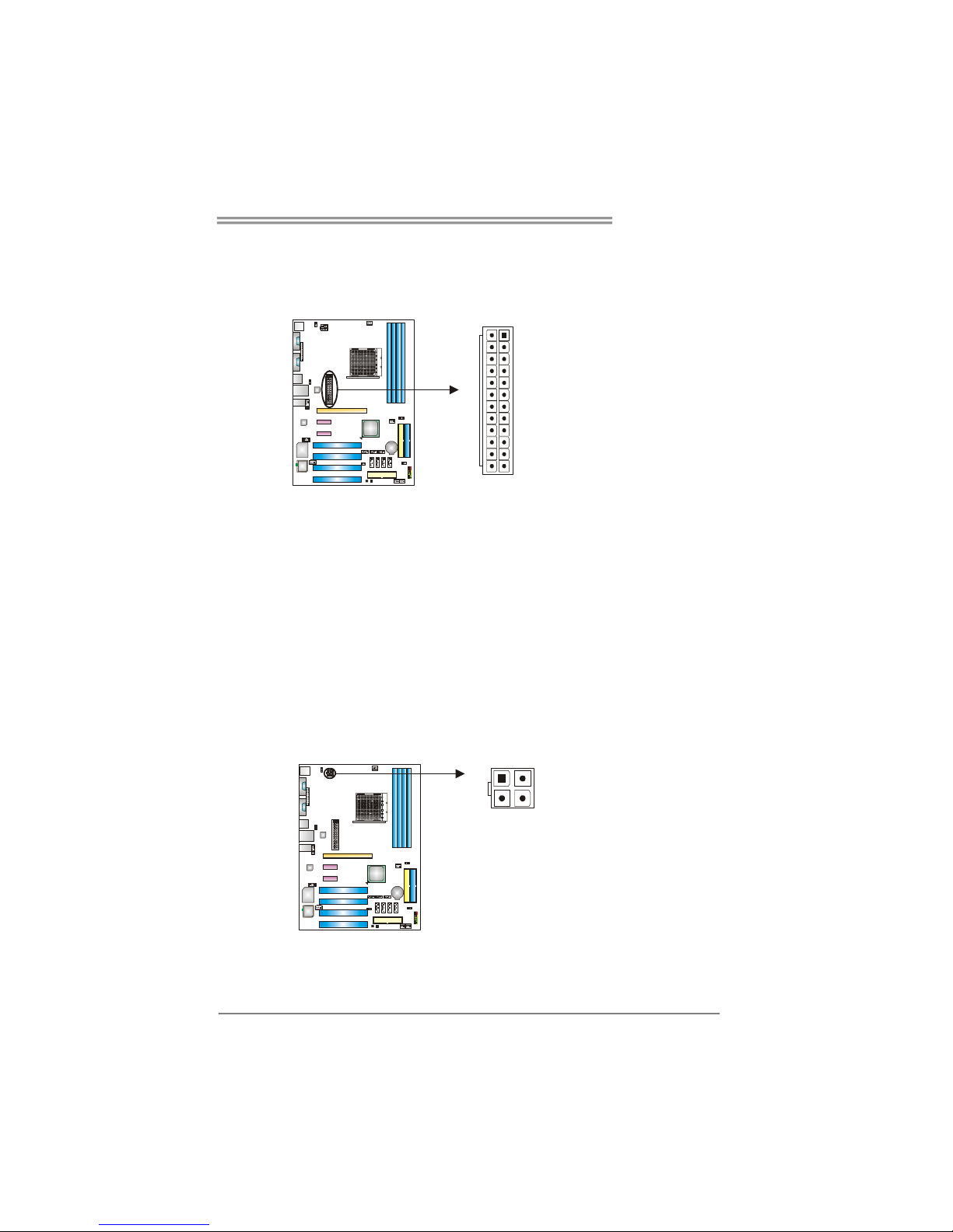
JATXPWR1: ATX Power Source Connector
This connector allows user to connect 24-pin power connector on the ATX
power supply.
113
1224
Pin Assignment Pin Assignment
13 +3.3V 1 +3.3V
14 -12V 2 +3.3V
15 Ground 3 Ground
16 PS_ON 4 +5V
17 Ground 5 Ground
18 Ground 6 +5V
19 Ground 7 Ground
20 NC 8 PW_OK
21 +5V 9 Standby Voltage+5V
22 +5V 10 +12V
23 +5V 11 +12V
24 Ground 12 +3.3V
JATXPWR2: ATX Power Source Connector
By connecting this connector, it will provide +12V to CPU power circuit.
Pin
Assignment
1 +12V
2 +12V
3 Ground
1
3
2
4
4 Ground
Page 16
Motherboard Manual
14
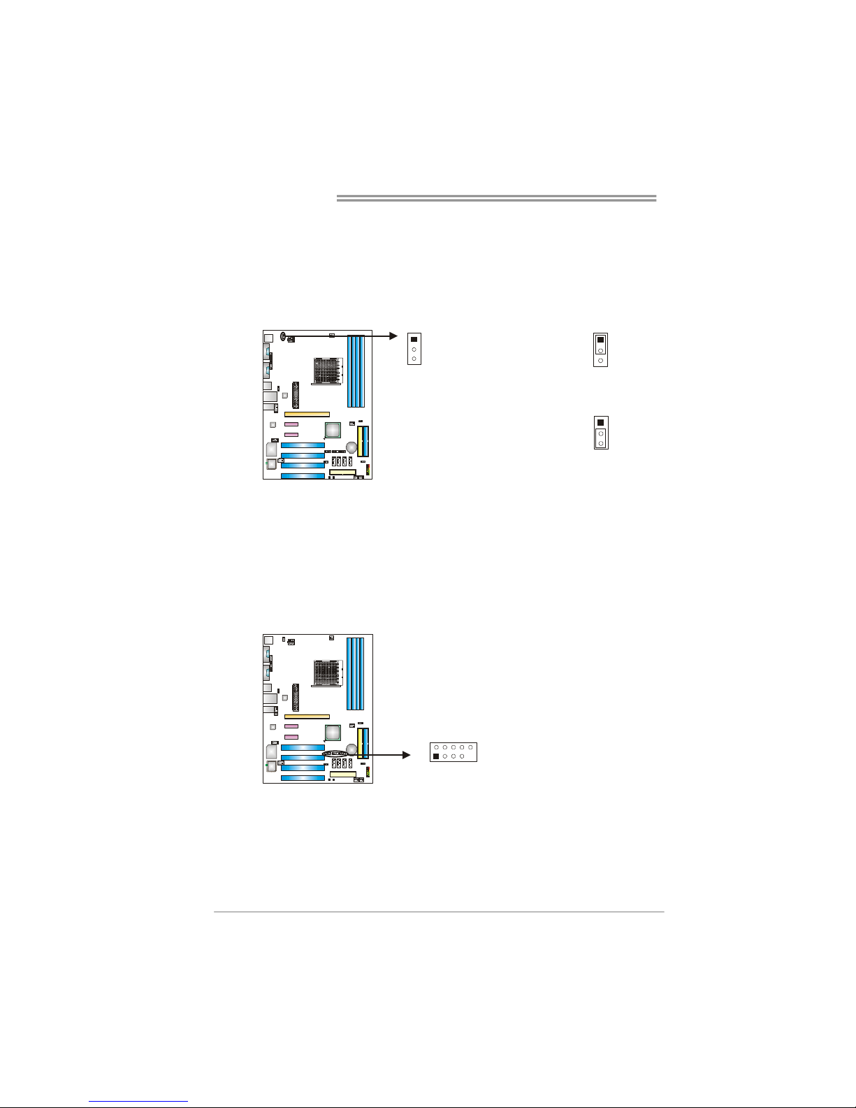
JKBMSV1: Power Source Selection Headers for Keyboard/Mouse
Pin 1-2 Close:
JKBMSV1: +5V for PS/2 keyboard and mouse。
Pin 2-3 Close:
JKBMSV1: PS/2 keyboard and mouse are powered with +5V standby
voltage.
1
3
Pin 1-2 close
1
3
1
3
Pin 2-3 close
JUSB2/JUSB3/JUSB4: Headers for USB 2.0 Ports at Front Panel
This header allows user to connect additional USB cable on the PC front panel,
and also can be connected with internal USB devices, like USB card reader.
Pin
Assignment
1 +5V (fused)
2 +5V (fused)
3 USB4 USB5 USB+
6 USB+
7 Ground
8 Ground
9 Key
JUSB2 JUSB3 JUSB4
1
2
9
10
10 NC
Page 17
TForce4 AM2
15
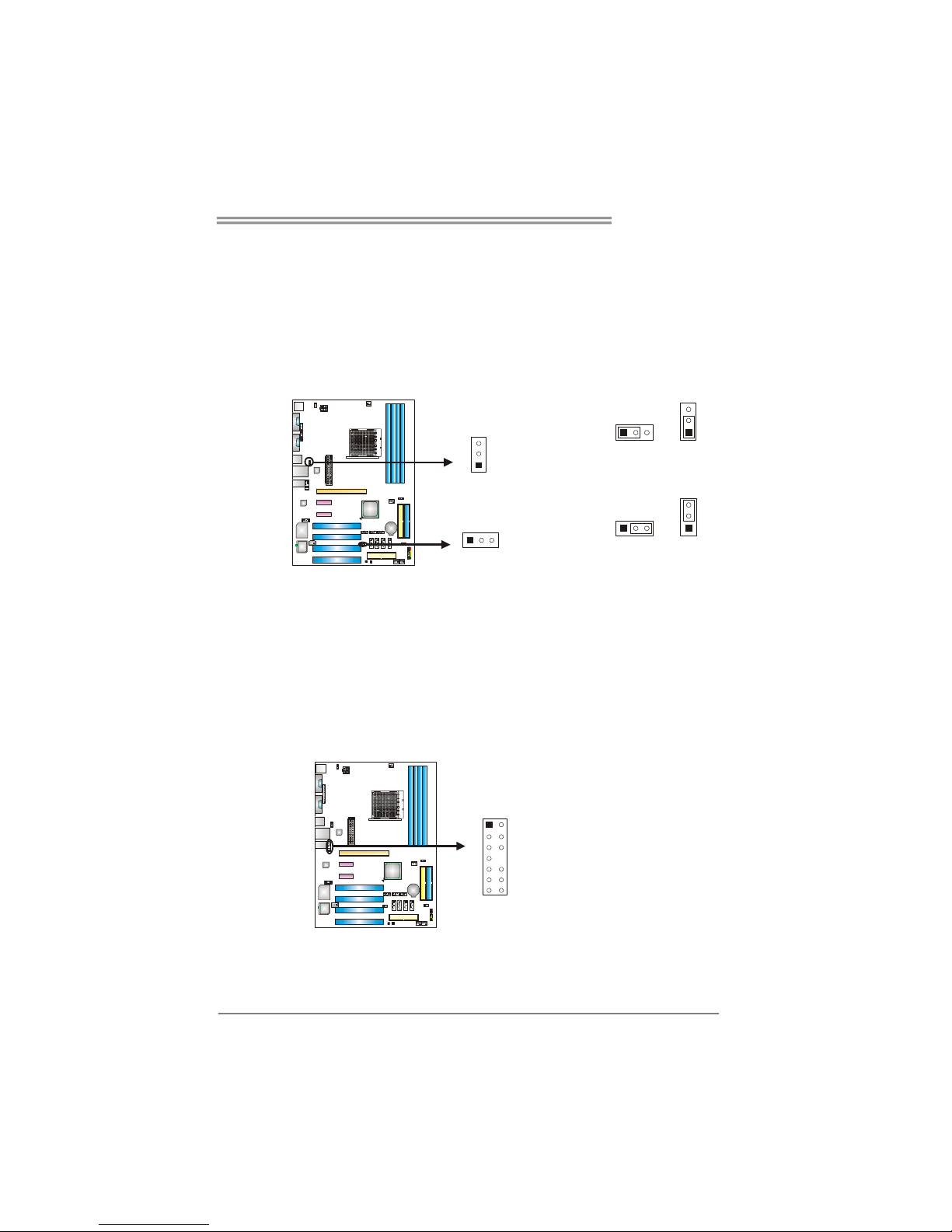
JUSBV1/JUSBV2: Power Source Headers for USB Ports
Pin 1-2 Close:
JUSBV1: +5V for USB ports at JUSBLAN1.
JUSBV2: +5V for USB ports at front panel (JUSB1/JUSB2/JUSB3).
Pin 2-3 Close:
JUSBV1: USB ports at JUSBLAN1 are powered by +5V standby voltage.
JUSBV2: USB ports at front panel (JUSB1/JUSB2/JUSB3) are powered by
+5V standby voltage.
3
1
1
3
Pin 1-2 close
JUSBV1
JUSBV2
113
3
3
1
1
3
Pin 2-3 close
Note:
In order to support this function “Power-On system via USB device,” “JUSBV1/ JUSBV2”
jumper cap should be placed on Pin 2-3 individually.
JFAUDIO1: Front Panel Audio Header
This header allows user to connect the front audio output cable with the PC front
panel. It will disable the output on back panel audio connectors.
Pin Assignment
1 Mic in/center
2 Ground
3 Mic power/Bass
4 Audio power
5 Right line out/
Speaker out Right
6 Right line out/
Speaker out Right
7 Reserved
8 Key
9 Left line out/
Speaker out Left
10 Left line out/
Speaker out Left
11 Right line in/
Rear speaker Right
12 Right line in/
Rear speaker Right
13 Left line in/
Rear speaker Left
1
13
2
14
14 Left line in/
Rear speaker Left
Page 18
Motherboard Manual
16
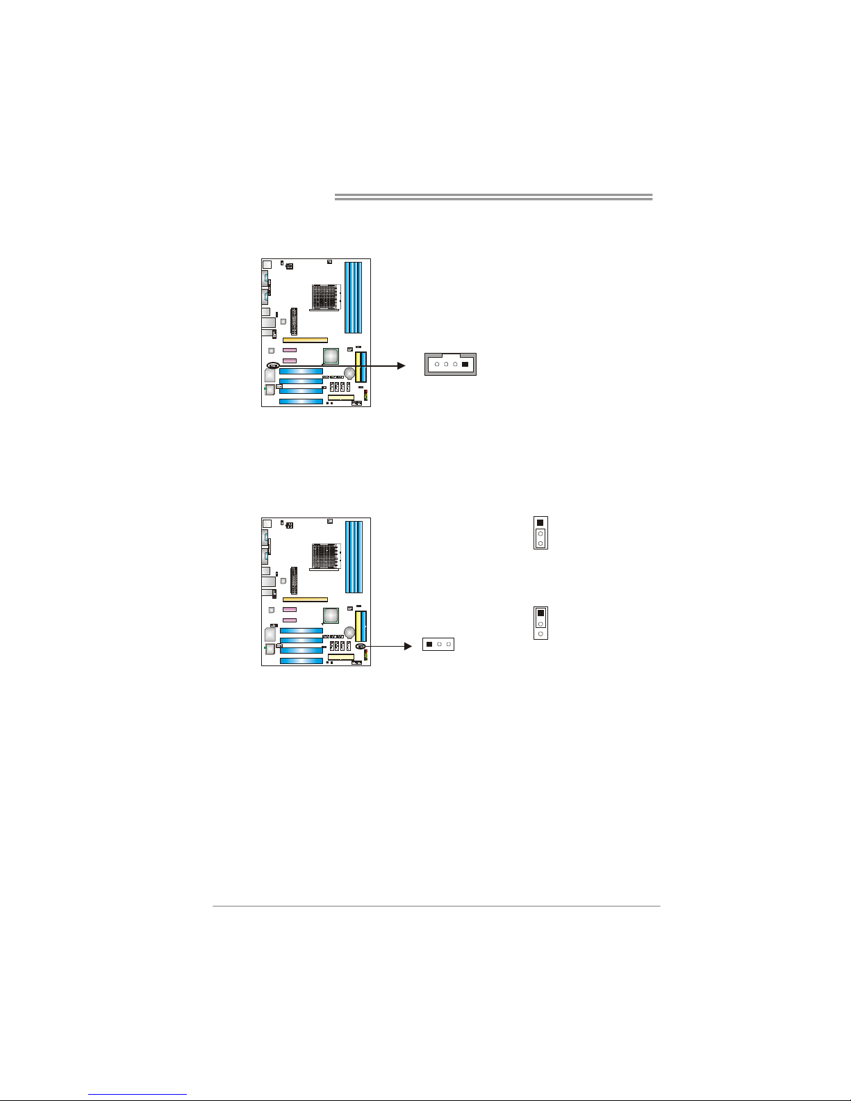
JCDIN1: CD-ROM Audio-in Connector
This connector allows user to connect the audio source from the variaty devices,
like CD-ROM, DVD-ROM, PCI sound card, PCI TV turner card etc..
Pin
Assignment
1 Left Channel Input
2 Ground
3 Ground
14
4 Right Channel Input
JCMOS1: Clear CMOS Header
By placing the jumper on pin2-3, it allows user to restore the BIOS safe setting
and the CMOS data, please carefully follow the procedures to avoid damaging
the motherboard.
1
3
Pin 1-2 Close:
Normal Operation (default).
13
1
3
Pin 2-3 Close:
Clear CMOS data.
※ Clear CMOS Procedures:
1. Remove AC power line.
2. Set the jumper to “Pin 2-3 close”.
3. Wait for five seconds.
4. Set the jumper to “Pin 1-2 close”.
5. Power on the AC.
6. Reset your desired password or clear the CMOS data.
Page 19
TForce4 AM2
17
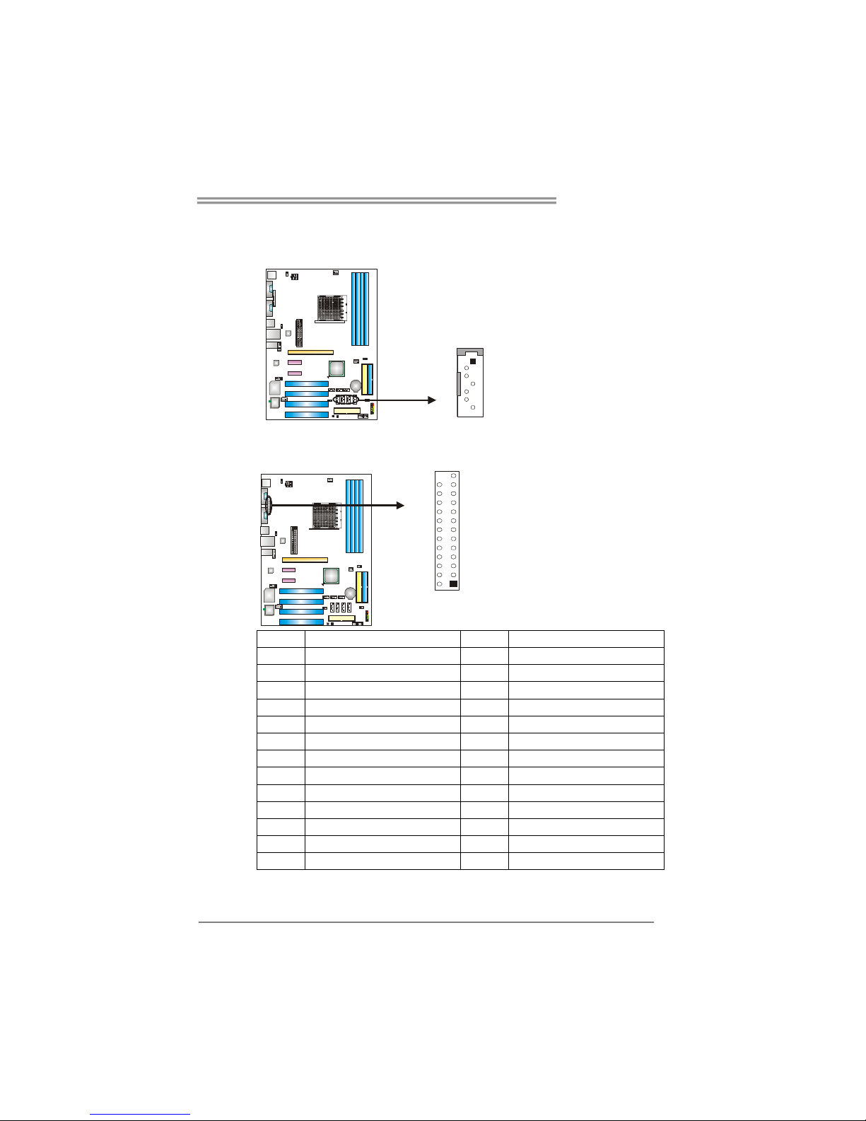
JSATA1~JSATA4: Serial ATA Connectors
The motherboard has a PCI to SATA Controller with 4 channels SATA interface,
it satisfies the SATA 1.0 spec and with transfer rate of 1.5Gb/s.
Pin
Assignment
1 Ground
2 TX+
3 TX4 Ground
5 RX6 RX+
JSATA1 JSATA2 JSATA3 JSATA4
1
4
7
7 Ground
JPRNT1: Printer Port Connector
This header allows you to connector printer on the PC.
12
25
Pin Assignment Pin Assignment
1 -Strobe 14 Ground
2 -ALF 15 Data 6
3 Data 0 16 Ground
4 -Error 17 Data 7
5 Data 1 18 Ground
6 -Init 19 -ACK
7 Data 2 20 Ground
8 -Scltin 21 Busy
9 Data 3 22 Ground
10 Ground 23 PE
11 Data 4 24 Ground
12 Ground 25 SCLT
13 Data 5
Page 20
Motherboard Manual
18
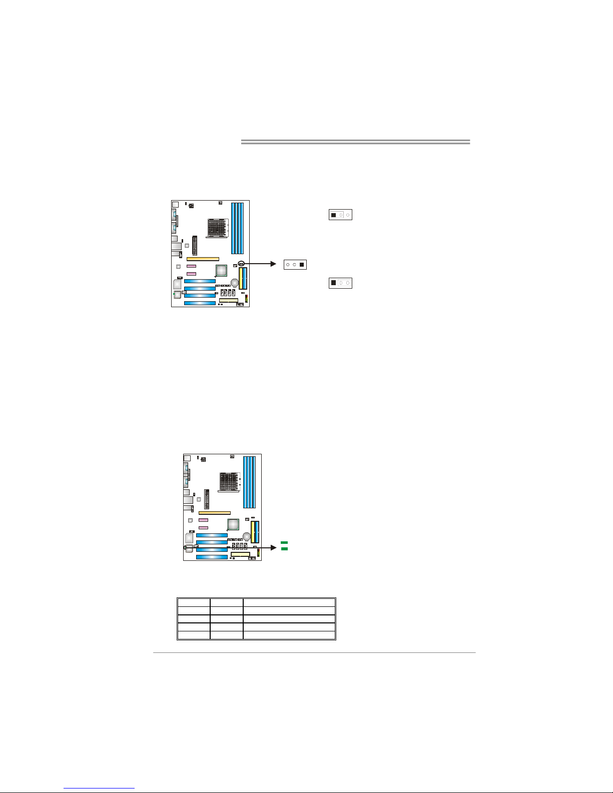
Header for Memory Voltage Overclocking: JDDRII_2.3V
When processing Memory Voltage Overclocking, please place the jumper to
pin1-2 Closed. The Default setting is Pin 2-3 Closed.
1
3
Pin 1-2 Close:
Memory voltage 2.3V.
13
1
3
Pin 2-3 Close:
Normal status (default).
Note:
1. When “JDDRII_2.3V” jumper cap is placed on Pin 2-3, memory voltage
can be manually adjusted under CMOS setup.
2. When “JDDRII_2.3V” jumper cap is placed on Pin 1-2, memory voltage
will be fixed at 2.3V automatically, and can’t be adjusted under COMS
setup.
Before setting memory voltage overclocking, please ensure that your DDR
supports up to 2.3V. (Consulting your DDR supplier)
On-Board LED Indicators
There are 2 LED indicators on the motherboard to show system status.
LED_D1
LED_D2
LED_D1 and LED_D2:
These 2 LED indicate system power on diagnostics.
Please refer to the table below for different messages:
LED_D1 LED_D2 Message
ON ON Normal
ON OFF Memory Error
OFF ON VGA Error
OFF OFF Abnormal: CPU / Chipset error.
Page 21
TForce4 AM2
19
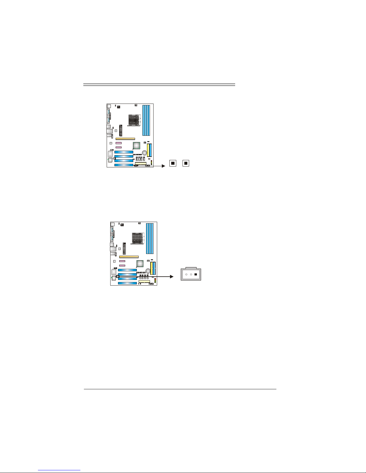
On-Board Buttons (optional)
There are 2 on-board buttons.
PWRSW RSTSW
(Optional)
(Optional)
PWRSW1:
This is an on-board Power Switch button.
RSTSW2:
This is an on-board Reset button.
JSPDIF_OUT1: Digital Audio-out Connector
This connector allows user to connect the PCI bracket SPDIF output header.
Pin
Assignment
1 +5V
2 SPDIF_OUT
13
3 Ground
Page 22
Motherboard Manual
20
CHAPTER 4: NVIDIA RAID FUNCTIONS
4.1 O
PERATION SYSTEM
z Supports Windows XP Home/Professional Edition, and Windows 2000 Professional.
4.2 RAID ARRAYS
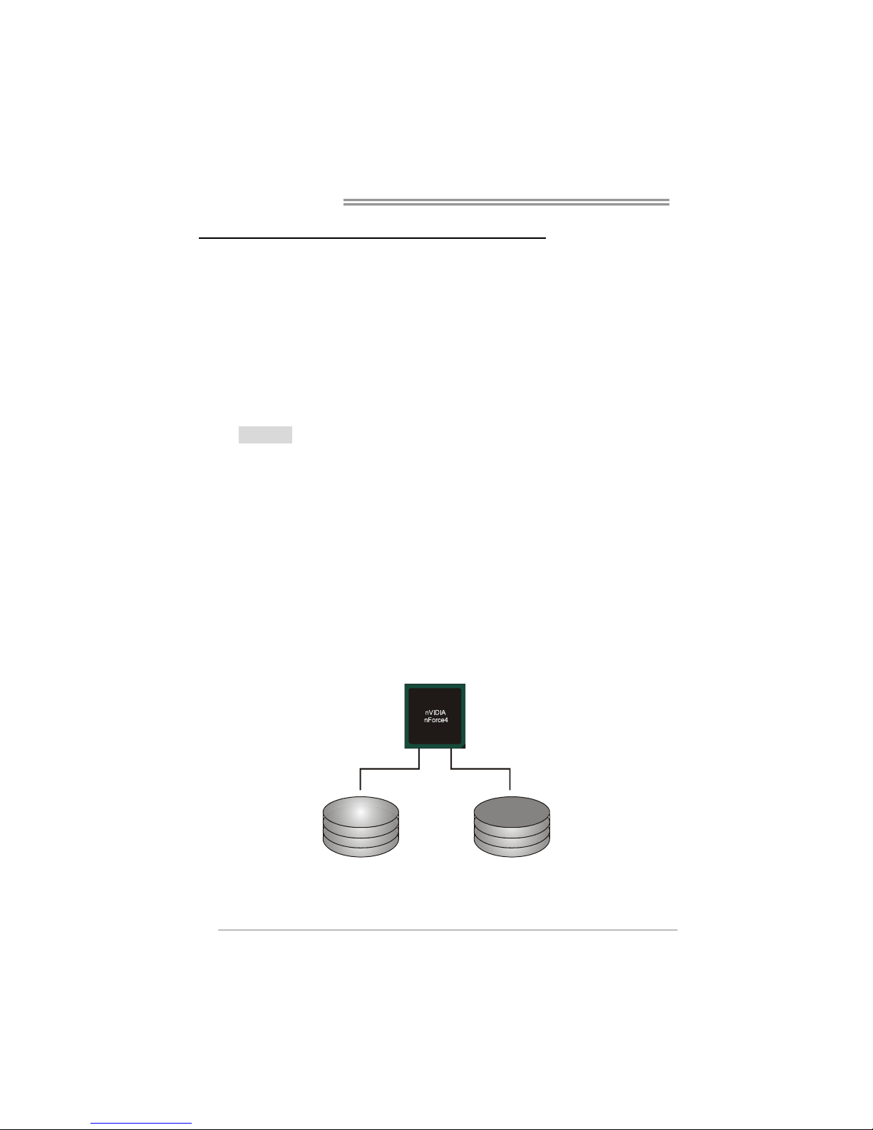
NVRAID supports the following types of RAID arrays:
RAID 0: RAID 0 defines a disk striping scheme that improves disk read and write times for
many applications.
RAID 1: RAID 1 defines techniques for mirroring data.
RAID 0+1: RAID 0+1 combines the techniques used in RAID 0 and RAID 1.
4.3 HOW RAID WORKS
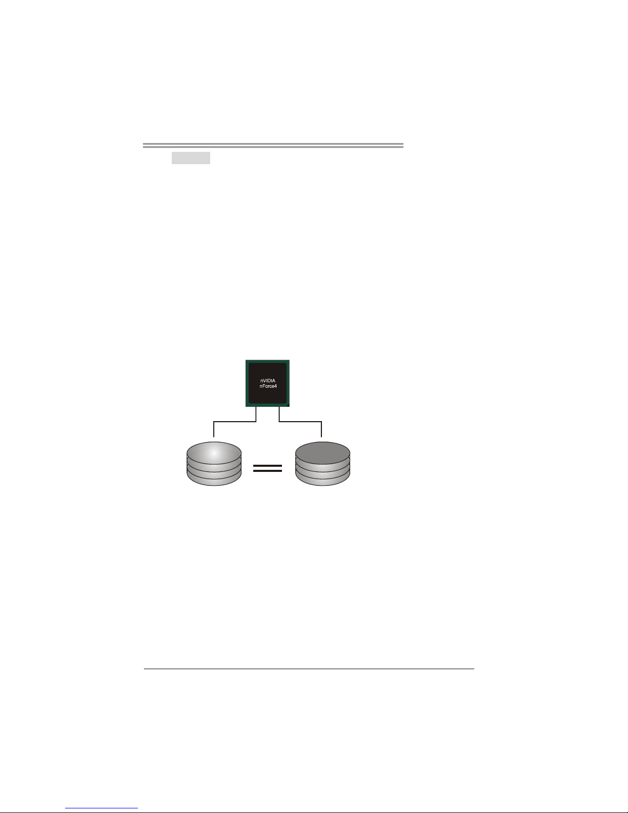
RAID 0:
The controller “stripes” data across multiple drives in a RAID 0 array system. It breaks
up a large file into smaller blocks and performs disk reads and writes across multiple
drives in parallel. The size of each block is determined by the stripe size parameter,
which you set during the creation of the RAID set based on the system environment. This
technique reduces overall disk access time and offers high bandwidth.
Features and Benefits
Drives: Minimum 1, and maximum is up to 6 or 8. Depending on the
platform.
Uses: Intended for non-critical data requiring high data throughput, or any
environment that does not require fault tolerance.
Benefits: provides increased data throughput, especially for large files. No
capacity loss penalty for parity.
Drawbacks: Does not deliver any fault tolerance. If any drive in the array
fails, all data is lost.
Fault Tolerance: No.
Block 1
Block 3
Block 5
Block 2
Block 4
Block 6
Page 23
TForce4 AM2
21
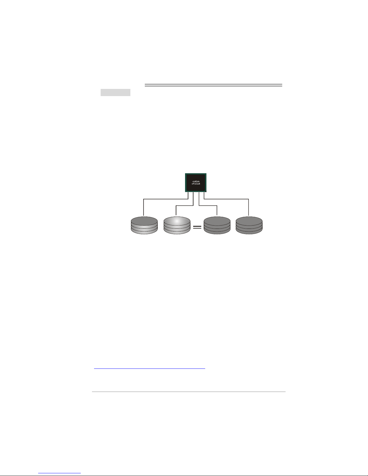
RAID 1:
Every read and write is actually carried out in parallel across 2 disk drives in a RAID 1
array system. The mirrored (backup) copy of the data can reside on the same disk or on
a second redundant drive in the array. RAID 1 provides a hot-standby copy of data if
the active volume or drive is corrupted or becomes unavailable because of a hardware
failure.
RAID techniques can be applied for high-availability solutions, or as a form of
automatic backup that eliminates tedious manual backups to more expensive and less
reliable media.
Features and Benefits
Drives: Minimum 2, and maximum is 2.
Uses: RAID 1 is ideal for small databases or any other application that
requires fault tolerance and minimal capacity.
Benefits: Provides 100% data redundancy. Should one drive fail, the
controller switches to the other drive.
Drawbacks: Requires 2 drives for the storage space of one drive.
Performance is impaired during drive rebuilds.
Fault Tolerance: Yes.
Block 1
Block 2
Block 3
Block 1
Block 2
Block 3
Page 24
Motherboard Manual
22
RAID 0+1:
RAID 0 drives can be mirrored using RAID 1 techniques. Resulting in a RAID 0+1
solution for improved performance plus resiliency.
Features and Benefits
- Drives: Minimum 4, and maximum is 6 or 8, depending on the platform.
- Benefits: Optimizes for both fault tolerance and performance, allowing for
automatic redundancy. May be simultaneously used with other RAID
levels in an array, and allows for spare disks.
- Drawbacks: Requires twice the available disk space for data redundancy,
the same as RAID level 1.
- Fault Tolerance: Yes.
Block 2
Block 4
Block 6
Block 1
Block 3
Block 5
Block 2
Block 4
Block 6
Block 1
Block 3
Block 5
※ For more detailed setup information, please refer to the Driver CD, or go to
http://www.nvidia.com/page/pg_20011106217193.html
to download NVIDIA nForce Tutorial
Flash.
Page 25

TForce4 AM2
23
CHAPTER 5: OVERCLOCK QUICK GUIDE
5.1: T-P
OWER INTRODUCTION
Biostar T-Power is a whole new utility that is designed for overclock users.
Based on many precise tests, Biostar Engineering Team (BET) has
developed this ultimate overclock engine to raise system performance.
No matter whether under BIOS or Windows interface, T-Power is able to
present the best system state according to users’ overclock setting.
T-Power BIOS Features:
Overclocking Navigator Engine (O.N.E.)
CMOS Reloading Program (C.R.P.)
Memory Integration Test (M.I.T., under Overclock Navigator Engine)
Integrated Flash Program (I.F.P.)
Smart Fan Function (under PC Health Status)
Self Recovery System (S.R.S)
T-Power Windows Feature:
Hardware Monitor
Overclock Engine
Smart Fan Function
Life Update
Page 26
Motherboard Manual
24
5.2: T-POWER BIOS FEATURE
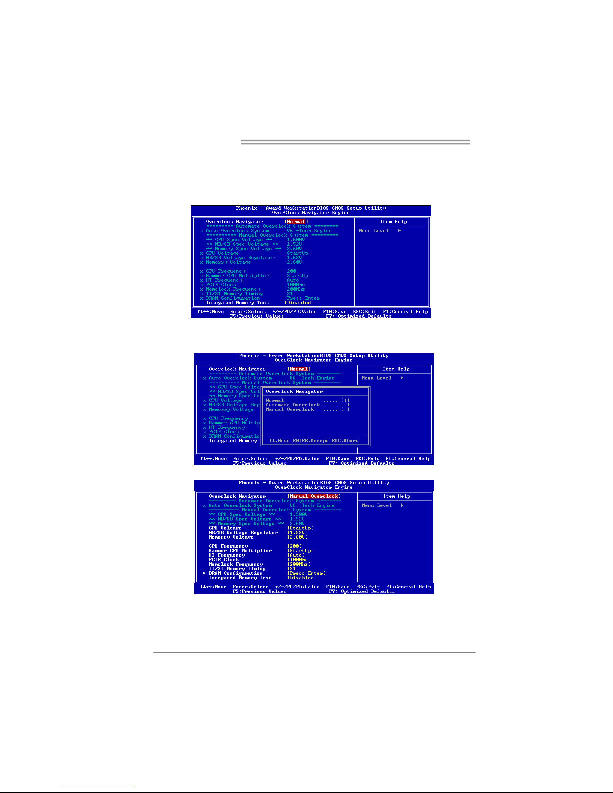
A. Overclocking Navigator Engine (O.N.E.):
ONE provides two powerful overclocking engines: MOS and AOS for both
Elite and Casual overclockers.
Manual Overclock System (M.O.S.)
MOS is designed for experienced overclock users.
It allows users to customize personal overclock settings.
Page 27

TForce4 AM2
25
CPU Overclock Setting:
CPU Voltage:
This function will increase CPU stability when overclocking. However, the
CPU temperature will increase when CPU voltage is increased.
Choices: The adjustable range is from 0.800V to 2.310V.
CPU Frequency:
CPU Frequency is directly in proportion to system performance. To
maintain the system stability, CPU voltage needs to be increased also
when raising CPU frequency.
Choices: This range is from 200 to 450, with an interval of 1MHz.
Memory Overclock Setting:
Memory Voltage:
This function will increase memory stability when overclocking.
Choices: The range is from 1.800V to 2.100V, with an interval of 0.100V.
Memclock Frequency:
To get better system performance, sometimes downgrading the memory
frequency is necessary when CPU frequency is adjusted over the upper
limit.
Choices: DDR2 400, DDR2 533, DDR2 667, DDR2 800 (MHz).
PCI-Express Overclock Setting:
PCIE Clock:
It helps to increase VGA card performance.
Choices: The range is from 100 to 145, with an interval of 1MHz.
Chipset Overclock Setting:
Chipset Voltage Regulator:
This function will increase chipset stability when overclocking.
Choices: 1.550V, 1.600V, 1.650V, 1.700V.
HT Frequency:
We recommend users to set this item at “x4” when overclocking.
Choices: x1, x2, x3, x4, x5, Auto.
Page 28
Motherboard Manual
26
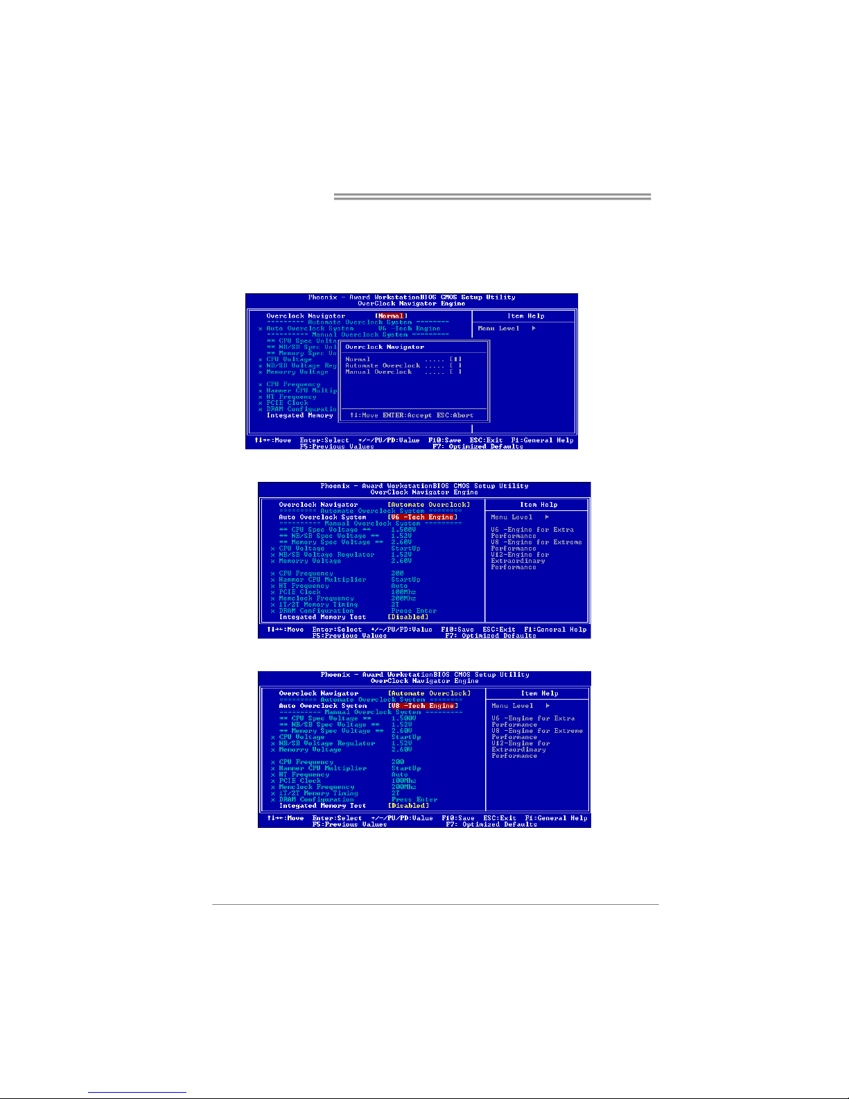
Automatic Overclock System (A.O.S.)
For beginners in overclock field, BET had developed an easy, fast, and
powerful feature to increase the system performance, named A.O.S.
Based on many tests and experiments, A.O.S. provides 3 ideal overclock
configurations that are able to raise the system performance in a single
step.
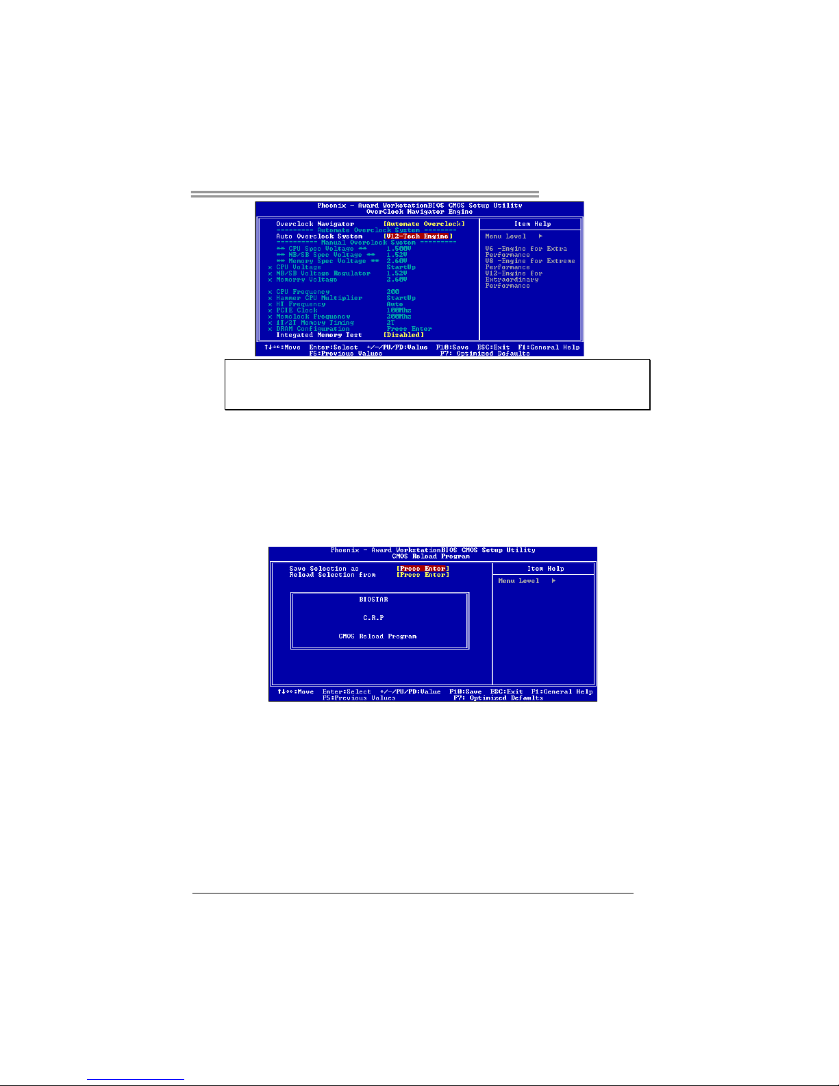
V6 Tech Engine:
This setting will raise about 10%~15% of whole system performance.
V8 Tech Engine:
This setting will raise about 15%~25% of whole system performance.
V12 Tech Engine:
This setting will raise about 25%~30% of whole system performance.
Page 29
TForce4 AM2
27
Notices:
1. Not all types of AMD CPU perform above overclock setting ideally; the difference will be based
on the selected CPU model.
2. From BET experiments, the Atholon64 FX CPU is not suitable for this A.O.S. feature.
B. CMOS Reloading Program (C.R.P.):
It allows users to save different CMOS settings into BIOS-ROM.
Users are able to reload any saved CMOS setting for customizing system
configurations.
Moreover, users are able to save an ideal overclock setting during overclock
operation.
There are 50 sets of record addresses in total, and users are able to name the
CMOS data according to personal preference.
Page 30
Motherboard Manual
28
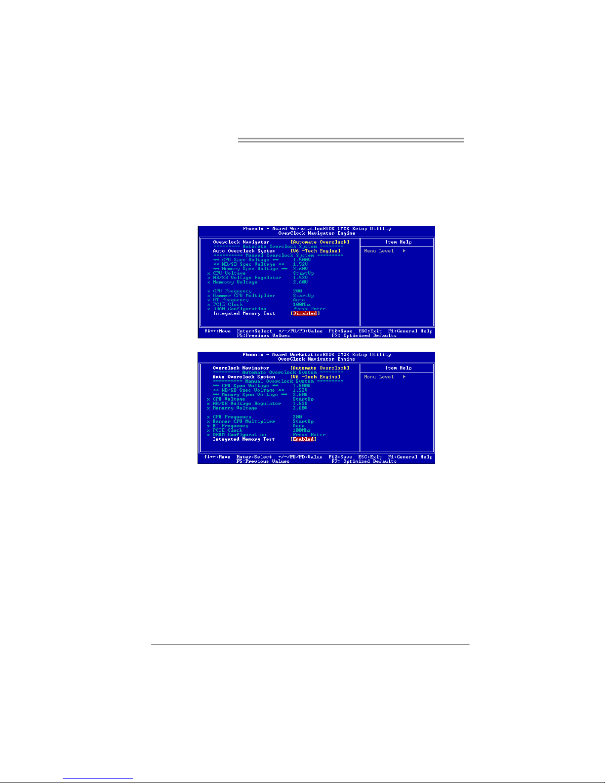
C. Memory Integration Test (M.I.T.):
This function is under “Overclocking Navigator Engine” item.
MIT allows users to test memory compatibilities, and no extra devices or
software are needed.
Step 1:
The default setting under this item is “Disabled”; the condition parameter should
be changed to “Enable” to proceed this test.
↓
Step 2:
Save and Exit from CMOS setup and reboot the system to activate this test.
Run this test for 5 minutes (minimum) to ensure the memory stability.
Step 3:
When the process is done, change the setting back from “Enable” to “Disable”
to complete the test.
Page 31
TForce4 AM2
29
D. Self Recovery System (S.R.S.):
This function can’t be seen under T-Power BIOS setup; and is always on
whenever the system starts up.
However, it can prevent system hang-up due to inappropriate overclock
actions.
When the system hangs up, S.R.S. will automatically log in the default BIOS
setting, and all overclock settings will be re-configured.
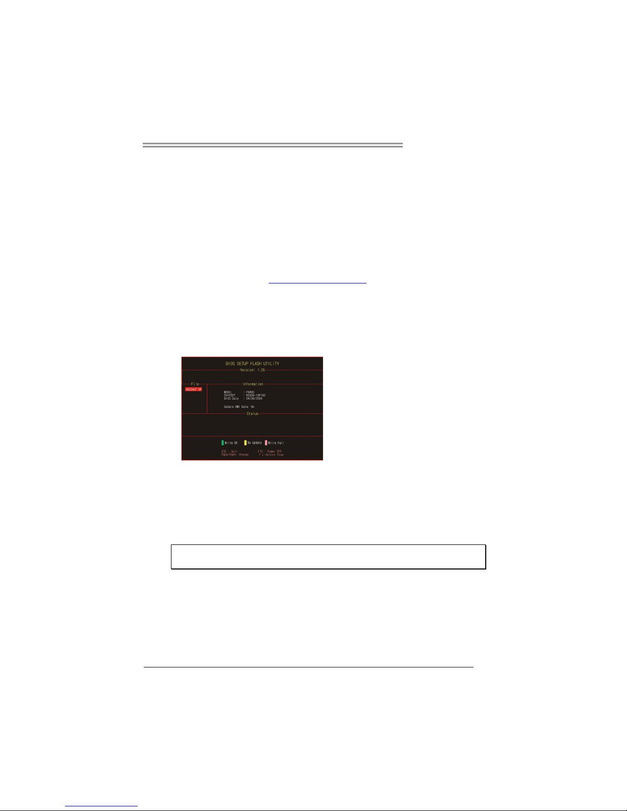
E. Integrated Flash Program (I.F.P.):
IFP is a safe and quick way to upgrade BIOS.
Step 1:
Go to Biostar website (http://www.biostar.com.tw
) to download the latest BIOS
file. Then, save the file into a floppy disk.
Step 2:
Insert the floppy disk and reboot the system to get into CMOS screen.
Step 3:
Select the item “Integrated Flash Program” to get the following frame and
choose the BIOS file downloaded in step 1.
Step 4:
Press “Enter” key to start BIOS file loading, and BIOS updating will process
automatically.
Step 5:
When the BIOS update is completed, press YES to the message “Flash done,
Reset system”, and the system will reboot automatically to finish the process.
Advise:
You can update the system BIOS by simply pressing “Enter” key for three times.
Page 32
Motherboard Manual
30
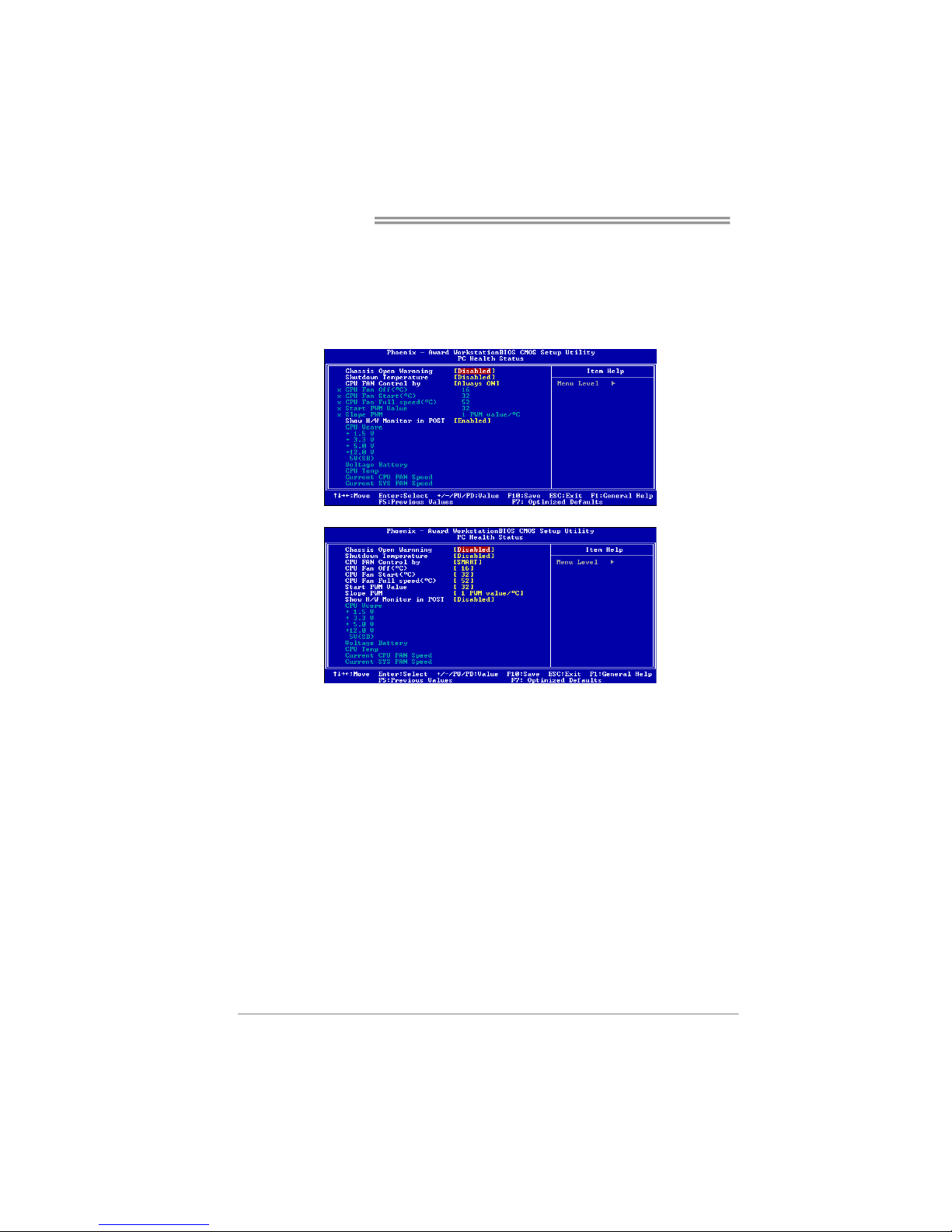
F. Smart Fan Function:
Smart Fan Function is under “PC Health Status”.
This is a brilliant feature to control CPU Temperature vs. Fan speed.
When enabling Smart Fan function, Fan speed is controlled automatically by
CPU temperature.
This function will protect CPU from overheat problem and maintain the system
temperature at a safe level.
↓
CPU Fan Off <℃>:
If the CPU temperature is lower than the set value, the CPU fan will turn
off. The range is from 0℃~127℃, with an interval of 1℃.
Choices: 16℃ (default).
CPU Fan Start <℃>
The CPU fan starts to work when CPU temperature arrives to this set
value. The range is from 0℃~127℃, with an interval of 1℃.
Choices: 32℃ (default).
CPU Fan Full speed <℃>
When CPU temperature arrives to the set value, the CPU fan will work
under Full Speed. The range is from 0℃~127℃, with an interval of 1℃.
Choices: 52℃ (default).
Page 33
TForce4 AM2
31
Start PWM Value
When CPU temperature arrives to the set value, the CPU fan will work
under Smart Fan Function mode. The range is from 0~127, with an
interval of 1.
Choices: 32 (default).
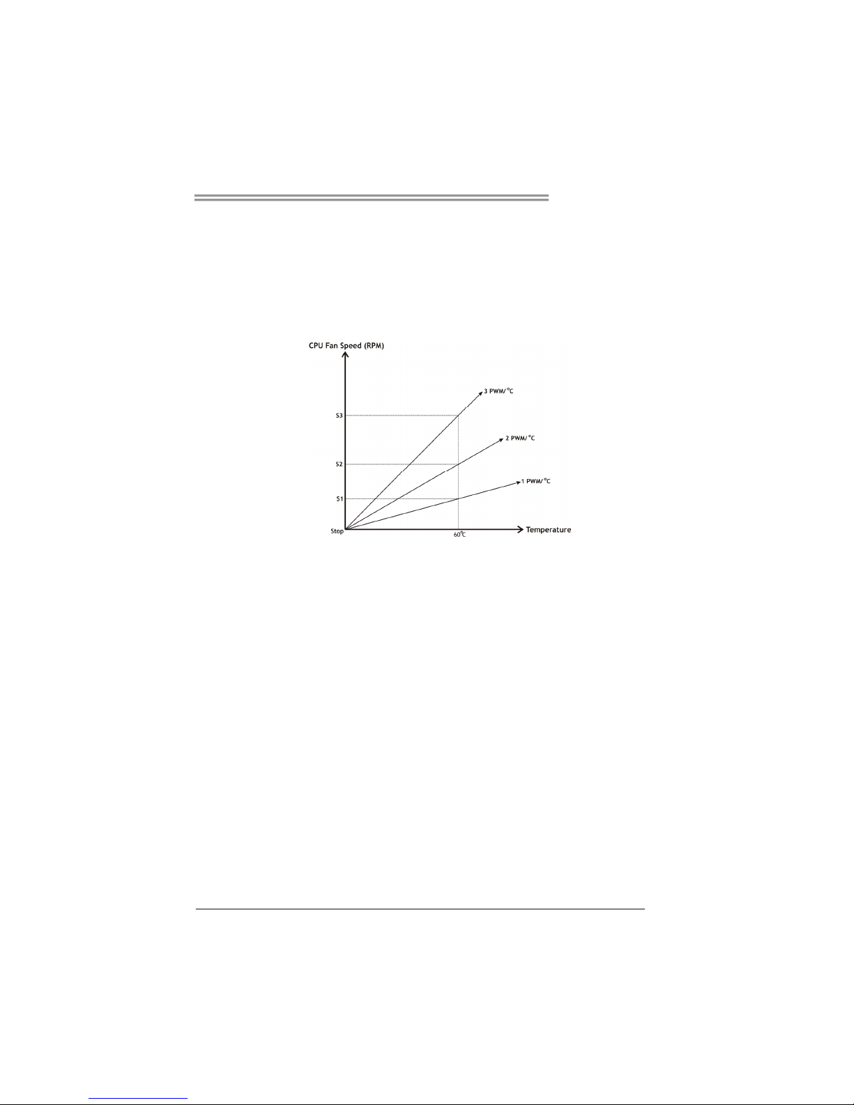
Slope PWM
Choices: 1 PWM Value/℃ (default), 2 PWM Value/℃, 4 PWM Value/℃, 8
PWM Value/℃, 16 PWM Value/℃, 32 PWM Value/℃, 64PWM Value/℃.
S1: CPU temperature is 60℃, and PWM value is 1 PWM/℃.
S2: CPU temperature is 60℃, and PWM value is 2 PWM/℃.
S3: CPU temperature is 60℃, and PWM value is 3 PWM/℃.
Increasing the value of slope PWM will raise the speed of CPU fan.
As in above diagram, when the CPU temperature reaches 60℃, the CPU
fan speed for 3 PWM/℃ is higher than 1 PWM/℃ (S1<S2<S3).
Page 34
Motherboard Manual
32
5.3 T-POWER WINDOWS FEATURE
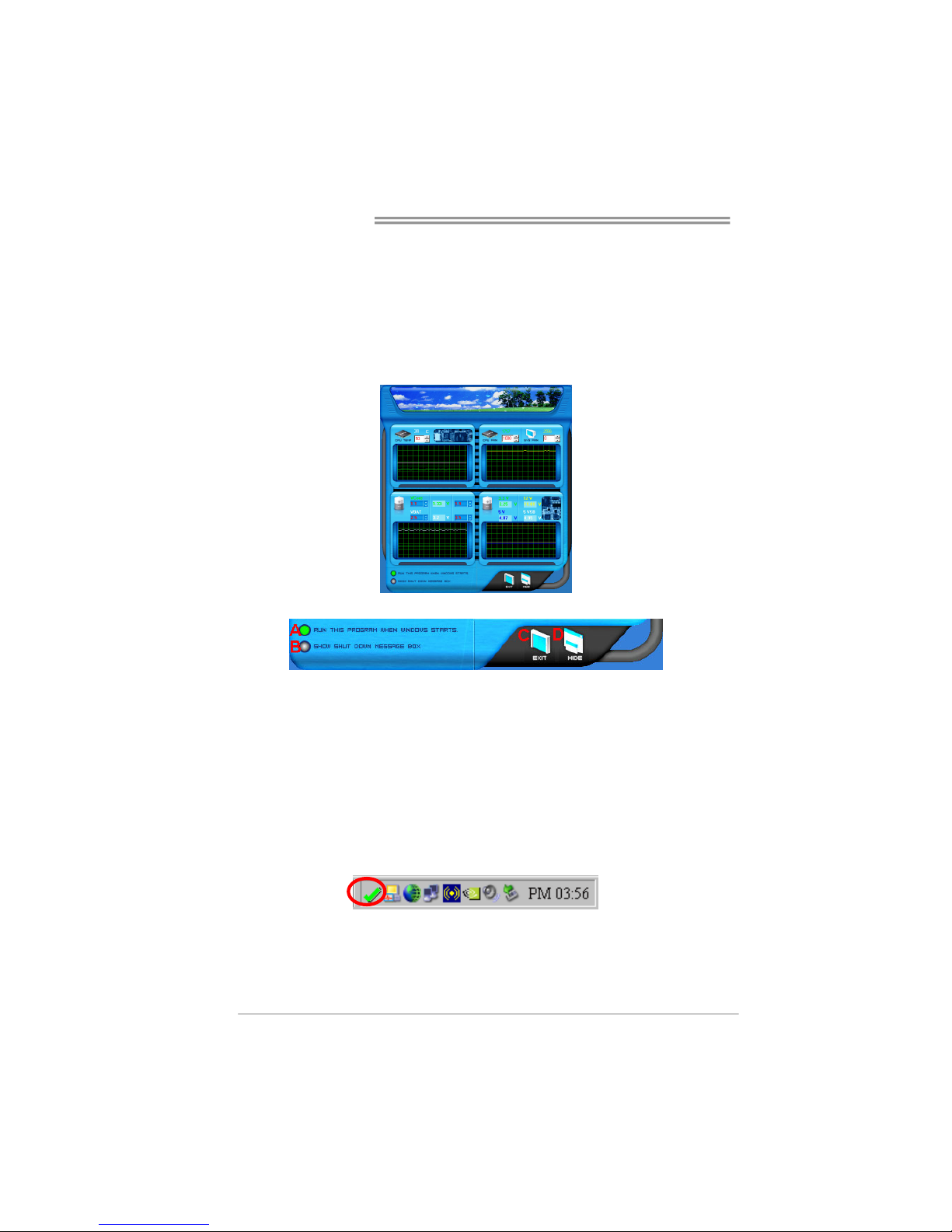
A.Hardware Monitor:
T-Power Hardware monitor allows users to monitor system voltage,
temperature and fan speed accordingly.
Additionally, a rescue action will be taken by the program automatically
while the system faces an abnormal condition. The program will trigger an
alarm or shut down the system when unpredictable errors occur.
All the monitoring items are illustrated by a waveform diagram.
Hardware Monitor Toolbar
i. Start-up Setting
Click on this item to run Hardware Monitor Program when the Windows
starts-up.
ii. Dialogue-Box Setting
Click on this item to pop-up warning dialogue-box when PC system is
abnormal.
iii. Exit
Click on this item to exit Hardware Monitor Program.
iv. Hide
Click on this item to hide this program in system tray. When hiding the
program, there will be a check icon in the system tray.
Page 35
TForce4 AM2
33
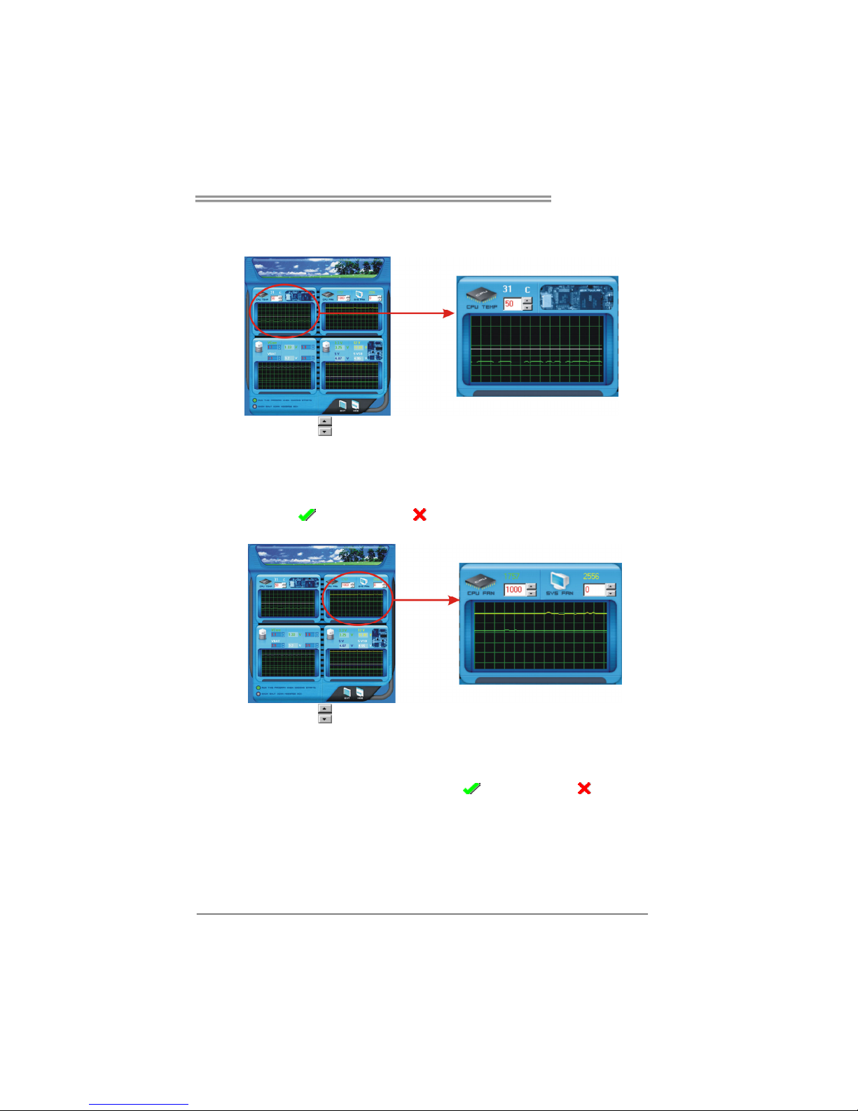
CPU Temperature
This column configures the CPU temperature. There is a waveform to
represent the status of CPU temperature.
By adjusting , users can easily configure the upper limit of CPU
temperature for system operating.
In this diagram, the white line represents the upper limit which user-set for CPU
temperature and the green line shows present CPU temperature.
If the CPU temperature is higher than the upper limit, the status line color will
change from green to red, and a warning sound will alert you. Also, the system
tray icon
would change to .
FAN Speed
By adjusting , users can easily configure the lower limit of the fan speed.
In this diagram, the green line shows present CPU Fan speed, and the yellow
line shows System Fan speed (if any).
If any one of the fans speeds is lower than the set value, the status line will
change into a red warning line, and the program will trigger an alarm system
automatically. Also, the system tray icon would change to .
Page 36
Motherboard Manual
34
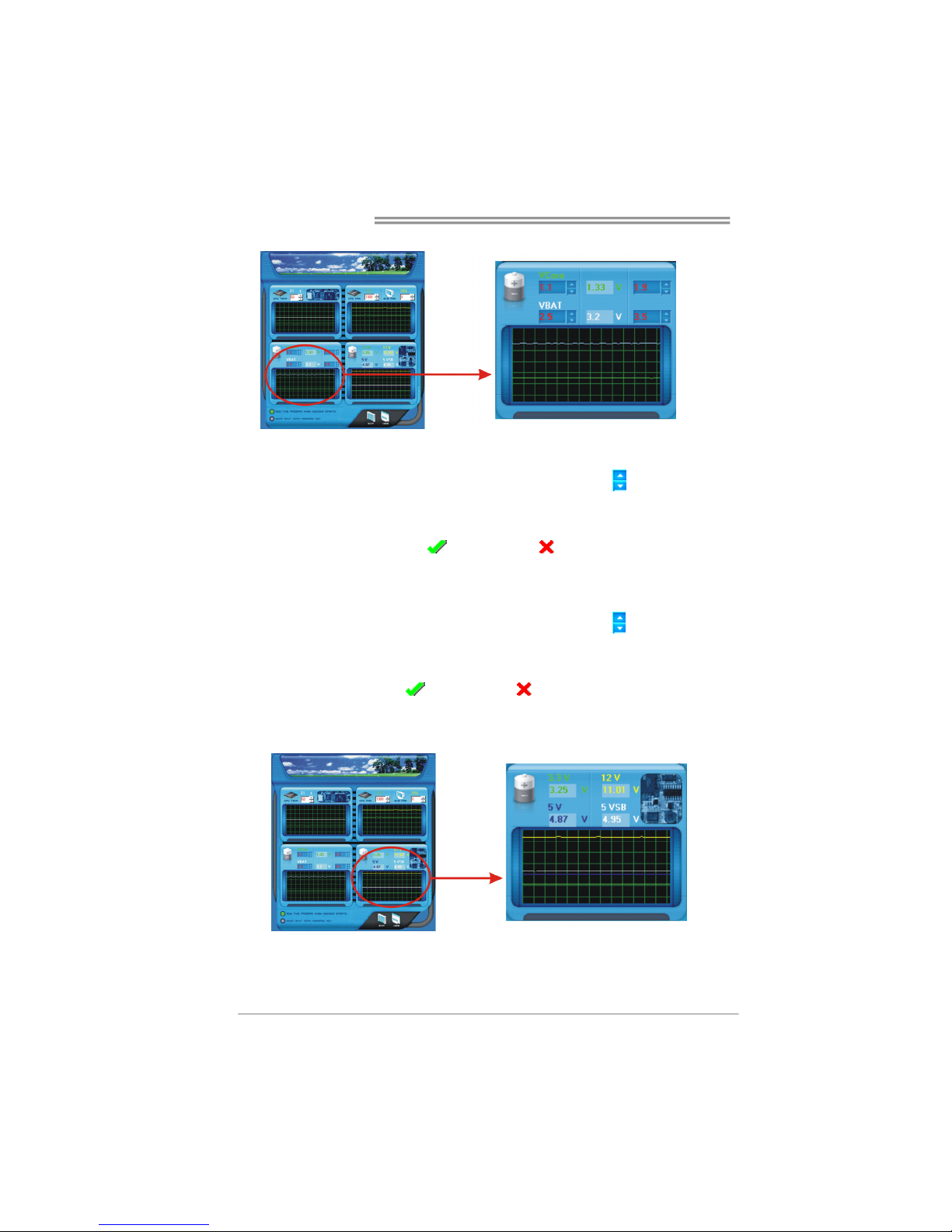
CPU/Battery Voltage
i. VCore
This item displays the CPU voltage, represented by a light blue line.
Users can set the upper and lower limit by adjusting
to monitor the
CPU operating voltage.
If CPU voltage is higher or lower than the set value, the status line will
change into a red warning line, and a warning sound will alert you. Also,
the system tray icon
will change to .
ii. VBAT
This item displays the CMOS battery voltage, represented by a light green
line.
Users can set the upper and lower limit by adjusting
to monitor the
status of battery voltage.
If battery voltage is higher or lower than the set value, the status line will
change to a red warning line, and a warning sound will alert you. Also, the
system tray icon will change to .
Reference data
This column represents the status of power supply voltage and cannot be
adjusted, it is only for present status reference.
Page 37
TForce4 AM2
35
B. Overclocking Configurations
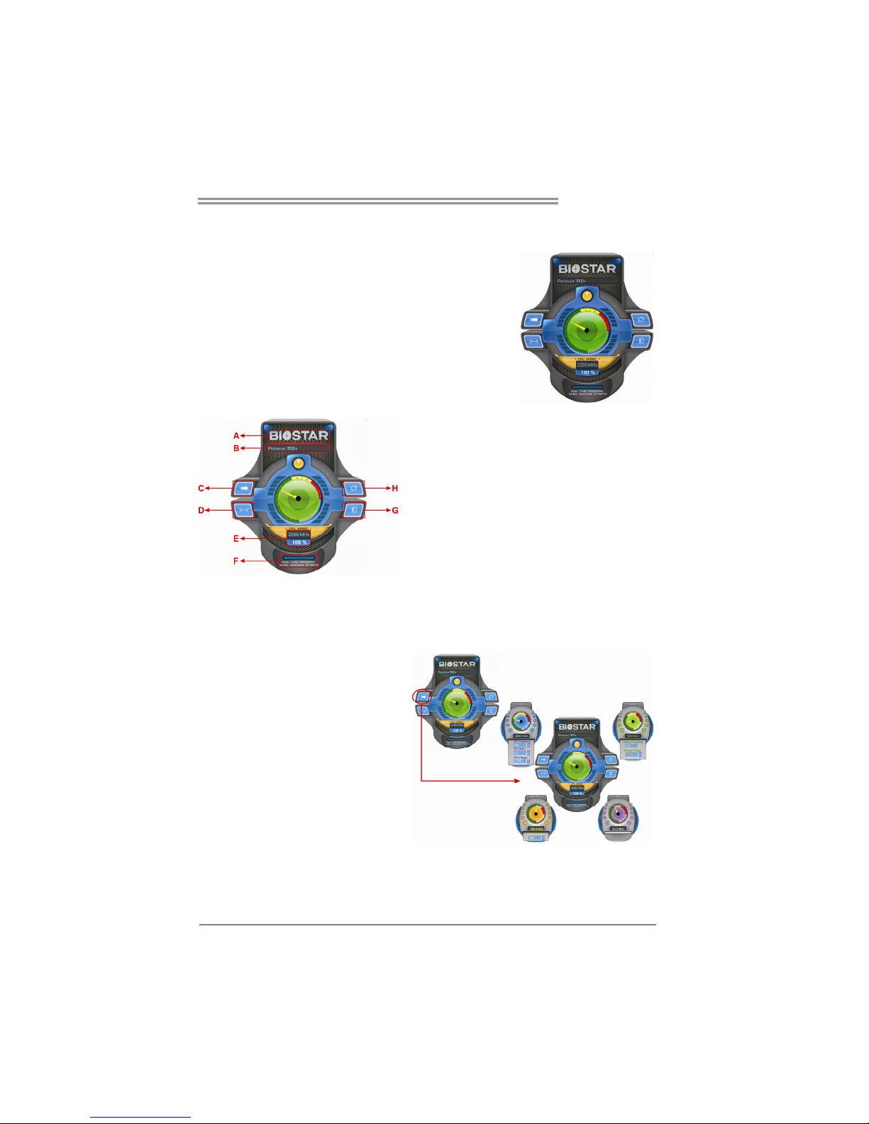
This diagram is designed for T-series
Overclocking utility. Friendly interface and solid
overclock features are the major concept of this
utility.
Graphic 1 will appear when activating this utility.
Graphic 1
Graphic 2
A. Clicking on “Biostar” will lead you to the
Biostar Homepage.
B. This column shows the CPU speed
information.
C. Click on this button and the utility will
pop-up 4 sub-screens (Please refers to
Graphic 3).
D. Click on this button to minimize this
program to taskbar.
E. This column shows present CPU speed
and overclocking percentage.
F. Clicking on this button will make the
program start up as soon as the
Windows starts up.
G. Click on this button to exit this overclock
utility.
H. Click on this button to reset all the
overclock features to default setting.
By adjusting the overclocking
features in 4 sub-screens, users can
tune the system performance to an
optimal level.
Graphic 3
Page 38
Motherboard Manual
36
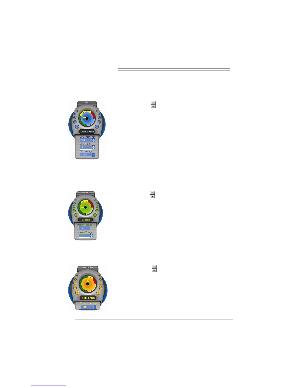
CPU Overclocking Settings:
By adjusting
can configure three items
for CPU overclocking.
A. CPU Frequency
Range: 200MHz~450MHz.
Interval: 1MHz.
B. CPU Ratio
Range: 4~25.
Interval: 1.
C. CPU Voltage
Range: 0.8V~2.0V.
Interval: 0.0125V.
Memory Overclocking Settings:
By adjusting
can configure two items for
Memory overclocking.
A. Memory Clock Frequency
Choices: 100, 133, 200, 266, 333, 400, 533,
667, 800.
B. Memory Voltage
Range: 1.8V~2.8V.
Interval: 0.1V.
AGP/PCI-Express Overclocking Setting:
By adjusting
can configure VGA card
overclocking. And this function helps to
increase VGA card performance.
Range: 100MHz~150MHz.
Interval: 1MHz.
Page 39
TForce4 AM2
37
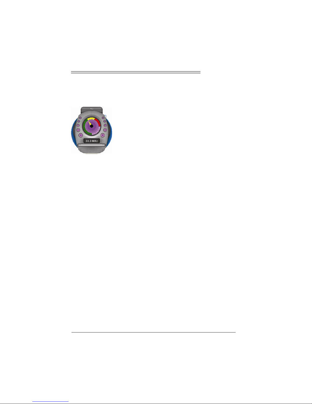
PCI Overclocking Setting:
This diagram shows present PCI working
status and helps to monitor PCI peripherals
working status.
This item cannot be adjusted.
Page 40
Motherboard Manual
38
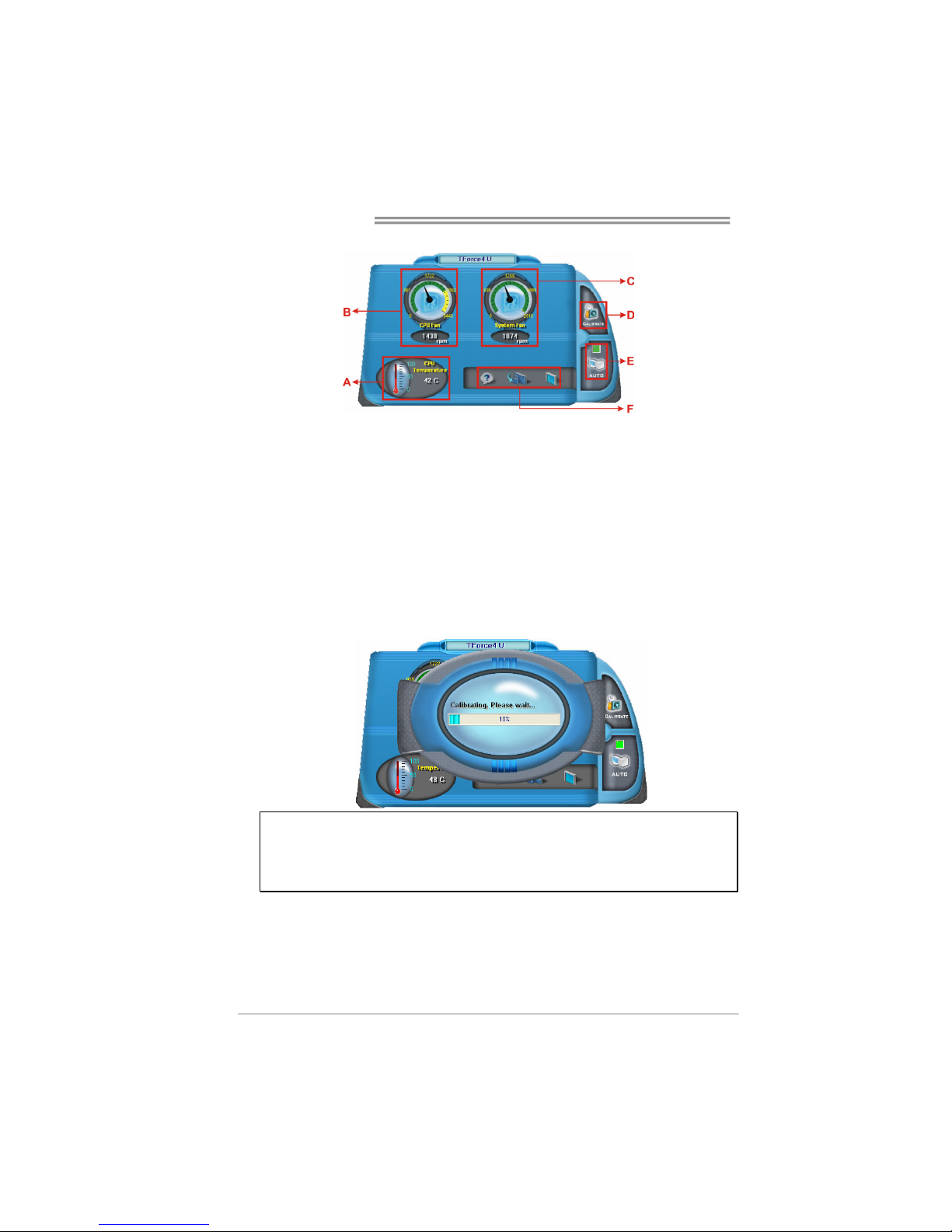
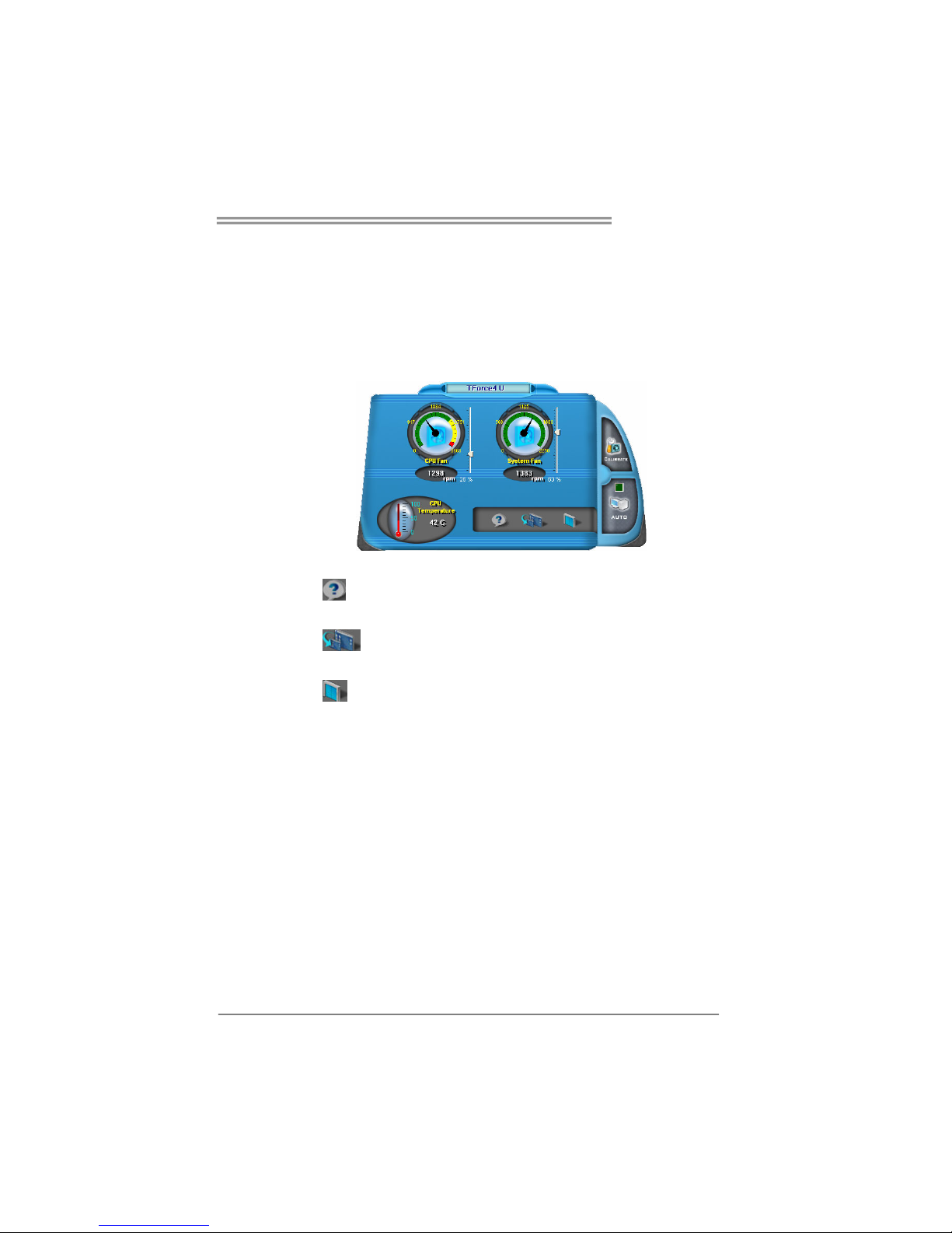
C. Smart Fan Function
When Smart Fan Function is activated, screens will pop-up to illustrate
the fan speed information.
i. CPU Temperature:
Show current CPU temperature.
ii. CPU Fan speed:
Show current CPU Fan speed.
iii. System Fan speed:
Show current system Fan speed.
iv. Calibrate:
When changing CPU Fan or System Fan, click on this button to
re-calibrate the Fan speed.
Note:
1. When Smart Fan Function activates for the first time, this calibrate function would
auto-run to get upper and lower limitation of CPU Fan and System Fan.
2. When calibrating process is done, the calibrating window will auto-close, and the
main screen will show new fan speed data.
Page 41
TForce4 AM2
39
v. Auto:
If the green indicator is lit up, the Smart Fan Function is “On”
(Default Setting).
Click on this button again to close Smart Fan Function, and a
screen as below would pop-up.
There will be pulling-meter besides the CPU Fan and System Fan,
the CPU Fan and the System Fan speed can be adjusted by
adjusting the Cursor Up or Down.
vi. Program Tool Bar:
z About:
Click on this button to get program-related information.
z
Minimize:
Click on this button to minimize the program to system tray
z
Exit:
Click on this button to exit this program.
Page 42
Motherboard Manual
40
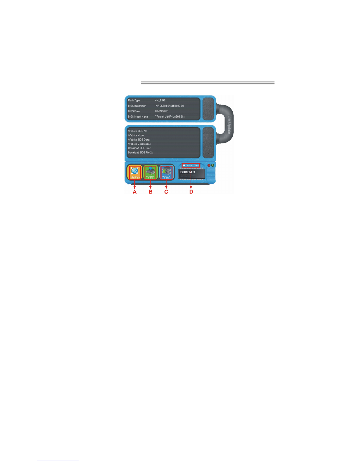
D. Live Update
When Live Update program is activated, a screen will pop up to illustrate
BIOS related information.
i. Link to Internet:
Click on this button will link to Biostar website and BIOS file will
be downloaded.
ii. Update BIOS:
Click on this button to run BIOS flashing process, and it’s easy
and safe.
iii. Backup BIOS:
Click on this button, and BIOS file will be saved into the
user-selected folder.
iv. Clear CMOS:
Click on this item will clear the CMOS Data. When carrying this
job, the previous CMOS data would be cleared and returned to
default setting.
Page 43
TForce4 AM2
41
CHAPTER 6: USEFUL HELP
6.1 D
RIVER INSTALLATION NOTE
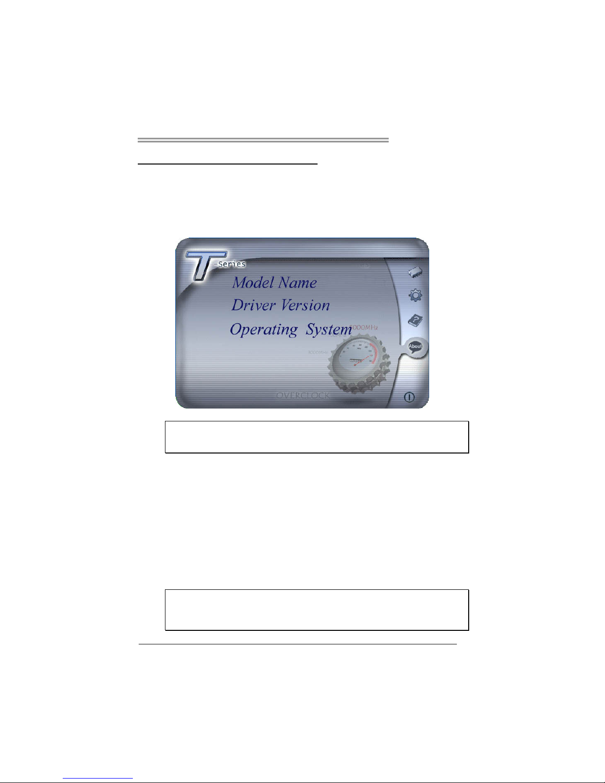
After you installed your operating system, please insert the Fully Setup
Driver CD into your optical drive and install the driver for better system
performance.
You will see the following window after you insert the CD
The setup guide will auto detect your motherboard and operating system.
Note:
If this window didn’t show up after you insert the Driver CD, please use file browser to
locate and execute the file SETUP.EXE under your optical drive.
A. Driver Installation
To install the driver, please click on the Driver icon. The setup guide will
list the compatible driver for your motherboard and operating system.
Click on each device driver to launch the installation program.
B. Software Installation
To install the software, please click on the Software icon. The setup guide
will list the software available for your system, click on each software title
to launch the installation program.
C. Manual
Aside from the paperback manual, we also provide manual in the Driver
CD. Click on the Manual icon to browse for available manual.
Note:
You will need Acrobat Reader to open the manual file. Please download the latest version
of Acrobat Reader software from
http://www.adobe.com/products/acrobat/readstep2.html
Page 44
Motherboard Manual
42
6.2 AWARD BIOS BEEP CODE
Beep Sound Meaning
One long beep followed by two short
beeps
Video card not found or video card
memory bad
High-low siren sound CPU overheated
System will shut down automatically
One Short beep when system boot-up No error found during POST
Long beeps every other second No DRAM detected or install
6.3 EXTRA INFORMATION
A. BIOS Update
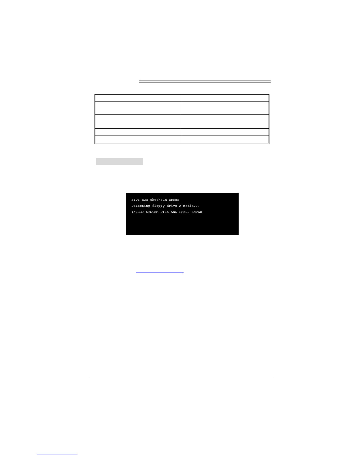
After you fail to update BIOS or BIOS is invaded by virus, the
Boot-Block function will help to restore BIOS. If the following message
is shown after boot-up the system, it means the BIOS contents are
corrupted.
In this Case, please follow the procedure below to restore the BIOS:
1. Make a bootable floppy disk.
2. Download the Flash Utility “AWDFLASH.exe” from the Biostar
website: www.biostar.com.tw
3. Confirm motherboard model and download the respectively BIOS
from Biostar website.
4. Copy “AWDFLASH.exe” and respectively BIOS into floppy disk.
5. Insert the bootable disk into floppy drive and press Enter.
6. System will boot-up to DOS prompt.
7. Type “Awdflash xxxx.bf/sn/py/r” in DOS prompt.
(xxxx means BIOS name.)
8. System will update BIOS automatically and restart.
9. The BIOS has been recovered and will work properly.
Page 45

TForce4 AM2
43
B. CPU Overheated
If the system shutdown automatically after power on system for
seconds, that means the CPU protection function has been activated.
When the CPU is over heated, the motherboard will shutdown
automatically to avoid a damage of the CPU, and the system may not
power on again.
In this case, please double check:
1. The CPU cooler surface is placed evenly with the CPU surface.
2. CPU fan is rotated normally.
3. CPU fan speed is fulfilling with the CPU speed.
After confirmed, please follow steps below to relief the CPU protection
function.
1. Remove the power cord from power supply for seconds.
2. Wait for seconds.
3. Plug in the power cord and boot up the system.
Or you can:
1. Clear the CMOS data.
(See “Close CMOS Header: JCMOS1” section)
2. Wait for seconds.
3. Power on the system again.
Page 46

Motherboard Manual
44
6.4 TROUBLESHOOTING
Probable Solution
1. No power to the system at all
Power light don’t illuminate, fan
inside power supply does not turn
on.
2. Indicator light on keyboard does
not turn on.
1. Make sure power cable is
securely plugged in.
2. Replace cable.
3. Contact technical support.
System inoperative. Keyboard lights
are on, power indicator lights are lit,
and hard drive is spinning.
Using even pressure on both ends of
the DIMM, press down firmly until the
module snaps into place.
System does not boot from hard disk
drive, can be booted from optical drive.
1. Check cable running from disk to
disk controller board. Make sure
both ends are securely plugged
in; check the drive type in the
standard CMOS setup.
2. Backing up the hard drive is
extremely important. All hard
disks are capable of breaking
down at any time.
System only boots from optical drive.
Hard disk can be read and applications
can be used but booting from hard disk
is impossible.
1. Back up data and applications
files.
2. Reformat the hard drive.
Re-install applications and data
using backup disks.
Screen message says “Invalid
Configuration” or “CMOS Failure.”
Review system’s equipment. Make sure
correct information is in setup.
Cannot boot system after installing
second hard drive.
1. Set master/slave jumpers
correctly.
2. Run SETUP program and select
correct drive types. Call the drive
manufacturers for compatibility
with other drives.
Page 47

TForce4 AM2
45
Page 48
Motherboard Manual
46
APPENDENCIES: SPEC IN OTHER LANGUAGE
G
ERMAN
Spezifikationen
CPU
Sockel AM2
AMD Athlon 64 / Athlon 64 FX / Althlon
64X2/ Sempron Prozessoren
Die AMD 64-Architektur unterstützt eine 32-Bit- und
64-Bit-Datenverarbeitung
Unterstützt Hyper Transport und Cool’n’Quiet
FSB
Unterstützt HyperTransport mit einer
Bandbreite von bis zu 1000 MHz
Chipsatz
nVIDIA nForce4
Super E/A
ITE 8712F
Bietet die häufig verwendeten alten
Super E/A-Funktionen.
Low Pin Count-Schnittstelle
Umgebungskontrolle,
Hardware-Überwachung
Lüfterdrehzahl-Controller
"Smart Guardian"-Funktion von ITE
Arbeitsspeich
er
DDR2 DIMM-Steckplätze x 4
Jeder DIMM unterstützt 256/512MB &
1GB DDR2.
Max. 4GB Arbeitsspeicher
Dual-Kanal DDR2 Speichermodul
Unterstützt DDR2 400 / 533 / 667 / 800 registrierte
DIMMs. Nicht-ECC DIMMs werden nicht unterstützt.
IDE Integrierter IDE-Controller
Ultra DMA 33 / 66 / 100 / 133 Bus Master-Modus
Unterstützt PIO-Modus 0~4,
SATA
Integrierter Serial ATA-Controller
Datentransferrate bis zu 1.5Gb/s
Konform mit der SATA-Spezifikation Version 1.0.
LAN
Realtek 8201CL PHY
10 / 100 Mb/s Auto-Negotiation
Halb-/ Vollduplex-Funktion
Audio-Codec
ALC 655 / 658 (optional)
6-Kanal-Audioausgabe
AC’97 Version 2.3
S/PDIF-Ausgang
PCI-Steckplatz x4
PCI Express x16 Steckplatz x1
Steckplätze
PCI Express x 1-Steckplatz x2
Diskettenlaufwerkanschluss x1 Jeder Anschluss unterstützt 2 Diskettenlaufwerke
Druckeranschluss Anschluss x1 Jeder Anschluss unterstützt 1 Druckeranschluss
IDE-Anschluss x2 Jeder Anschluss unterstützt 2 IDE-Laufwerke
SATA-Anschluss x4 Jeder Anschluss unterstützt 1 SATA-Laufwerk
Fronttafelanschluss x1 Unterstützt die Fronttafelfunktionen
Front-Audioanschluss x1 Unterstützt die Fronttafel-Audioanschlussfunktion
CD-IN-Anschluss x1 Unterstützt die CD Audio-In-Funktion
Onboard-Ans
chluss
S/PDIF-Ausgangsanschluss x1 Unterstützt die digitale Audioausgabefunktion
Page 49

TForce4 AM2
47
Spezifikationen
CPU-Lüfter-Sockel x1
CPU-Lüfterstromversorgungsanschluss (mit Smart
Fan-Funktion)
System-Lüfter-Sockel x3 System-Lüfter-Stromversorgungsanschluss
"Gehäuse offen"-Sockel (optional) x1 Zur Erkennung eines geöffneten Gehäuses
"CMOS löschen"-Sockel x1
USB-Anschluss x3 Jeder Anschluss unterstützt 2
Fronttafel-USB-Anschlüsse
Stromanschluss (24-polig) x1
Stromanschluss (4-polig) x1
Rückseiten-E
/A
PS/2-Tastatur x1
PS/2-Maus x1
Serieller Anschluss x1
LAN-Anschluss x1
USB-Anschluss x4
Audioanschluss x3
Platinengröße
.
218 mm (B) X 293 mm (L)
Sonderfunkti
onen
NVIDIA nTunes
Unterstützt RAID 0 / 1 / 0+1
OS-Unterstüt
zung
Windows 2K / XP
Biostar behält sich das Recht vor, ohne Ankündigung die
Unterstützung für ein Betriebssystem hinzuzufügen
oder zu entfernen.
Page 50
Motherboard Manual
48
FRANCE
SPEC
UC
Socket AM2
Processeurs AMD Athlon 64 / Athlon 64 FX
/ Althlon 64X2 / Sempron
L'architecture AMD 64 permet le calcul 32 et 64 bits
Prend en charge Hyper Transport et Cool’n’Quiet
Bus frontal
Prend en charge Hyper Transport jusqu'à
une bande passante de 1000 MHz
Chipset
nVIDIA nForce4
Super E/S
ITE 8712F
Fournit la fonctionnalité de Super E/S
patrimoniales la plus utilisée.
Interface à faible compte de broches
Initiatives de contrôle environnementales,
Moniteur de matériel
Contrôleur de vitesse de ventilateur
Fonction "Gardien intelligent" de l'ITE
Mémoire
principale
Fentes DDR2 DI M M x 4
Chaque DIMM prend en charge des DDR2
de 256/512 Mo et 1Go
Capacité mémoire maximale de 4 Go
Module de mémoire DDR2 à mode à double voie
Prend en charge la DDR2 400 / 533 / 667 / 800
Les DIMM à registres et DIMM sans code correcteurs
d'erreurs ne sont pas prises en charge
IDE
Contrôleur IDE intégré
Mode principale de Bus Ultra DMA 33 / 66 / 100 / 133
Prend en charge le mode PIO 0~4,
SATA
Contrôleur Serial ATA intégré :
Taux de transfert jusqu'à 1.5 Go/s.
Conforme à la spécification SATA Version 1.0
LAN
Realtek 8201CL PHY
10 / 100 Mb/s négociation automatique
Half / Full duplex capability
Codec audio ALC 655 / 658 (optional)
Sortie audio à 6 voies
AC’97 Version 2.3
Sortie (entrée) S/PDIF
Fente PCI x4
Slot PCI Express x16 x1
Fentes
Slot PCI Express x 1 x2
Connecteur de disquette x1
Chaque connector prend en charge 2 lecteurs de
disquettes
Connecteur de Port d'imprimante x1 Chaque connector prend en charge 1 Port d'imprimante
Connecteur IDE x2
Chaque connecteur prend en charge 2 périphériques
IDE
Connecteur SATA x4
Chaque connecteur prend en charge 1 périphérique
SATA
Connecteur du panneau avant x1 Prend en charge les équipements du panneau avant
Connecteur Audio du panneau avantx1 x1 Prend en charge la fonction audio du panneau avant
Connecteur
embarqué
Connecteur d'entrée CD x1 Prend en charge la fonction d'entrée audio de CD
Page 51
TForce4 AM2
49
SPEC
Connecteur de sortie S/PDIF x1 Prend en charge la fonction de sortie audio numérique
Embase de ventilateur UC x1
Alimentation électrique du ventilateur UC (avec
fonction de ventilateur intelligent)
Embase de ventilateur système x3 Alimentation électrique du ventilateur système
Embase d'ouverture de châssis x1
(optional)
Pour la fonction de détection d'intrus dans le châssis
Embase d'effacement CMOS x1
Connecteur USB x3
Chaque connecteur prend en charge 2 ports USB de
panneau avant
Connecteur d'alimentation x1
(24 broches)
Connecteur d'alimentation x1
(4 broches)
E/S du
panneau
arrière
Clavier PS/2 x1
Souris PS/2 x1
Port série x1
Port LAN x1
Port USB x4
Fiche audio x3
Dimensions
de la carte
218 mm (l) X 293 mm (H)
Fonctionnali
tés
spéciales
NVIDIA nTunes
Prise en charge RAID 0 / 1 / 0+1
Support SE Windows 2K / XP
Biostar se réserve le droit d'ajouter ou de supprimer le
support de SE avec ou sans préavis.
Page 52
Motherboard Manual
50
ITALIAN
SPECIFICA
CPU
Socket AM2
Processori AMD Athlon 64 / Athlon 64
FX / Althlon 64X2 / Sempron
L’architettura AMD 64 abilita la computazione 32
e 64 bit
Supporto di Hyper Transport e Cool’n’Quiet
FSB
Supporto di HyperTransport fino a
1000 MHz di larghezza di banda
Chipset
nVIDIA nForce4
Super I/O
ITE 8712F
Fornisce le funzionalità legacy Super
I/O usate più comunemente.
Interfaccia LPC (Low Pin Count)
Funzioni di controllo dell’ambiente:
Monitoraggio hardware
Controller velocità ventolina
Funzione "Smart Guardian" di ITE
Memoria
principale
Alloggi DIMM DDR2 x 4
Ciascun DIMM supporta DDR2
256/512MB e 1GB
Capacità massima della memoria 4GB
Modulo di memoria DDR2 a canale doppio
Supporto di DDR2 400 / 533 / 667 / 800
DIMM registrati e DIMM Non-ECC non sono
supportati
IDE
Controller IDE integrato
Modalità Bus Master Ultra DMA 33 / 66 / 100 /
133
Supporto modalità PIO Mode 0-4
SATA
Controller Serial ATA integrato
Velocità di trasferimento dei dati fino
a 1.5 Gb/s.
Compatibile specifiche SATA Versione 1.0.
LAN
Realtek 8201CL
Negoziazione automatica 10 / 100 Mb/s
Capacità Half / Full Duplex
Codec
audio
ALC 655 / 658(optional)
Uscita audio 6 canali
AC’97 Versione 2.3
Output S/PDIF
Alloggio PCI x4
Alloggio PCI Express x16 x1
Alloggi
Alloggio PCI Express x1 x2
Connettore floppy x1 Ciascun connettore supporta 2 unità Floppy
Connettore Porta stampante x1 Ciascun connettore supporta 1 Porta stampante
Connettore IDE x2 Ciascun connettore supporta 2 unità IDE
Connettore SATA x4 Ciascun connettore supporta 1 unità SATA
Connettore pannello frontale x1 Supporta i servizi del pannello frontale
Connettore audio frontale x1 Supporta la funzione audio pannello frontale
Connettore CD-in x1 Supporta la funzione input audio CD
Connettore output SPDIF x1 Supporta la funzione d’output audio digitale
Collettore ventolina CPU x1
Alimentazione ventolina CPU (con funzione Smart
Fan)
Collettore ventolina sistema x3 Alimentazione ventolina di sistema
Connettori
su scheda
Collettore apertura telaio x1
(optional)
Per la funzione di rilevamento intrusione telaio
Page 53
TForce4 AM2
51
SPECIFICA
Collettore cancellazione CMOS x1
Connettore USB x3
Ciascun connettore supporta 2 porte USB
pannello frontale
Connettore alimentazione x1
(24 pin)
Connettore alimentazione x1
(4 pin)
I/O
pannello
posteriore
Tastiera PS/2 x1
Mouse PS/2 x1
Porta seriale x1
Porta LAN x1
Porta USB x4
Connettore audio x3
Dimension
i scheda
218 mm (larghezza) x 293 mm
(altezza)
Caratterist
iche
speciali
nTunes NVIDIA
Supporto RAID 0 / 1 / 0+1
Sistemi
operativi
supportati
Windows 2K / XP
Biostar si riserva il diritto di aggiungere o
rimuovere il supporto di qualsiasi sistema
operativo senza preavviso.
Page 54
Motherboard Manual
52
SPANISH
Especificación
CPU
Conector AM2
Procesadores AMD Athlon 64 / Athlon 64
FX / Athlon 64X2 / Sempron
La arquitectura AMD 64 permite el procesado de 32 y
64 bits
Soporta las tecnologías Hyper Transport y Cool’n’Quiet
FSB
Admite HyperTransport con un ancho de
banda de hasta 1000 MHz
Conjunto de
chips
nVIDIA nForce4
Súper E/S
ITE 8712F
Le ofrece las funcionalidades heredadas de
uso más común Súper E/S.
Interfaz de cuenta Low Pin
Iniciativas de control de entorno,
Monitor hardware
Controlador de velocidad de ventilador
Función "Guardia inteligente" de ITE
Memoria
principal
Ranuras DIMM DDR2 x 4
Cada DIMM admite DDR de 256/512MB y
1GB
Capacidad máxima de memoria de 4GB
Módulo de memoria DDR2 de canal Doble
Admite DDR2 de 400 / 533 / 667 / 800
No admite DIMM registrados o DIMM no compatibles
con ECC
IDE Controlador IDE integrado
Modo bus maestro Ultra DMA 33 / 66 / 100 / 133
Soporte los Modos PIO 0~4,
SATA
Controlador ATA Serie Integrado
Tasas de transferencia de hasta 1.5 Gb/s.
Compatible con la versión SATA 1.0.
Red Local
Realtek 8201CL PHY
Negociación de 10 / 100 Mb/s
Funciones Half / Full dúplex
Códecs de
sonido
ALC 655 / 658 (opcional)
Salida de sonido de 6 canales
AC’97 Versión 2.3
Salida S/PDIF
Ranura PCI X4
Ranura PCI Express x16 X1
Ranuras
Ranura PCI express x 1 X2
Conector disco flexible X1 Cada conector soporta 2 unidades de disco flexible
Conector Puerto de impresora X1 Cada conector soporta 1 Puerto de impresora
Conector IDE X2 Cada conector soporta 2 dispositivos IDE
Conector SATA X4 Cada conector soporta 1 dispositivos SATA
Conector de panel frontal X1 Soporta instalaciones en el panel frontal
Conector de sonido frontal X1 Soporta funciones de sonido en el panel frontal
Conector de entrada de CD X1 Soporta función de entrada de sonido de CD
Conectores
en placa
Conector de salida S/PDIF X1 Soporta función de salida de sonido digital
Page 55
TForce4 AM2
53
Especificación
Cabecera de ventilador de CPU X1 Fuente de alimentación de ventilador de CPU (con
función Smart Fan)
Cabecera de ventilador de sistema X3 Fuente de alimentación de ventilador de sistema
Cabecera de chasis abierto(opcional) X1 Función de detección de intrusos en el chasis
Cabecera de borrado de CMOS X1
Conector USB X3 Cada conector soporta 2 puertos USB frontales
Conector de alimentación X1
(24 patillas)
Conector de alimentación X1
(4 patillas)
Panel
trasero de
E/S
Teclado P S/ 2 X 1
Ratón PS/2 X1
Puerto serie X1
Puerto de red local X1
Puerto USB X4
Conector de sonido X3
Tamaño d e
la placa
218 mm. (A) X 293 Mm. (H)
Funciones
especiales
NVIDIA nTunes
Admite RAID 0 / 1 / 0+1
Soporte de
sistema
operativo
Windows 2K / XP
Biostar se reserva el derecho de añadir o retirar el
soporte de cualquier SO con o sin aviso previo.
Page 56
Motherboard Manual
54
PORTUGUESE
ESPECIFICAÇÕES
CPU
Socket AM2
Processadores AMD Athlon 64 / Athlon 64
FX / Althlon 64X2 / Sempron
A arquitectura AMD 64 permite uma computação de 32
e 64 bits
Suporta as tecnologias Hyper Transport e Cool’n’Quiet
FSB
Suporta a tecnologia HyperTransport com
uma largura de banda até 1000 MHz
Chipset
nVIDIA nForce4
Especificaçã
o Super I/O
ITE 8712F
Proporciona as funcionalidades mais
utilizadas em termos da especificação
Super I/O.
Interface LPC (Low Pin Count).
Iniciativas para controlo do ambiente
Monitorização do hardware
Controlador da velocidade da ventoinha
Função "Smart Guardian" da ITE
Memória
principal
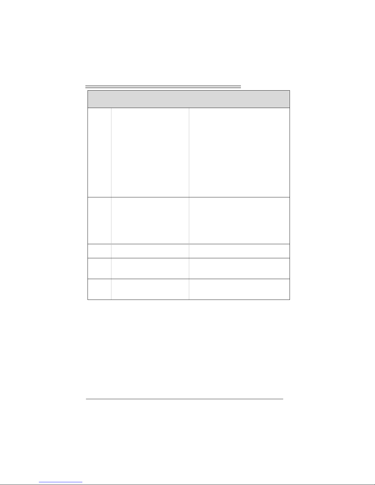
Ranhuras DIMM DDR2 x 4
Cada módulo DIMM suporta uma
memória DDR2 de 256/512 MB & 1 GB
Capacidade máxima de memória: 4 GB
Módulo de memória DDR2 de canal duplo
Suporta módulos DDR2 400 / 533 / 667 / 800
Os módulos DIMM registados e os DIMM Non-ECC não
são suportados
IDE
Controlador IDE integrado
Modo Bus master Ultra DMA 33 / 66 / 100 / 133
Suporta o modo PIO 0~4,
SATA
Controlador Serial ATA integrado
Velocidades de transmissão de dados até
1.5 Gb/s.
Compatibilidade com a especificação SATA versão 1.0.
LAN
Realtek 8201CL PHY
Auto negociação de 10 / 100 Mb/s.
Capacidade semi/full-duplex
Codec de
som
ALC 655 / 658 (opcional)
Saída de áudio de 6 canais
AC’97 Versão 2.3
Saída S/PDIF
Ranhura PCI x4
Ranhura PCI Express x16 x1
Ranhuras
Ranhura PCI Express x 1 x2
Conector da unidade de disquetes x1 Cada conector suporta 2 unidades de disquetes
Conector da para impressora x1 Cada conector suporta 1 Porta para impressora
Conector IDE x2 Cada conector suporta 2 dispositivos IDE
Conector SATA x4 Cada conector suporta 1 dispositivo SATA
Conector do painel frontal x1 Para suporte de várias funções no painel frontal
Conector de áudio frontal x1 Suporta a função de áudio no painel frontal
Conectores
na placa
Conector para entrada de CDs x1 Suporta a entrada de áudio a partir de CDs
Page 57
TForce4 AM2
55
ESPECIFICAÇÕES
Conector de saída S/PDIF x1 Suporta a saída de áudio digital
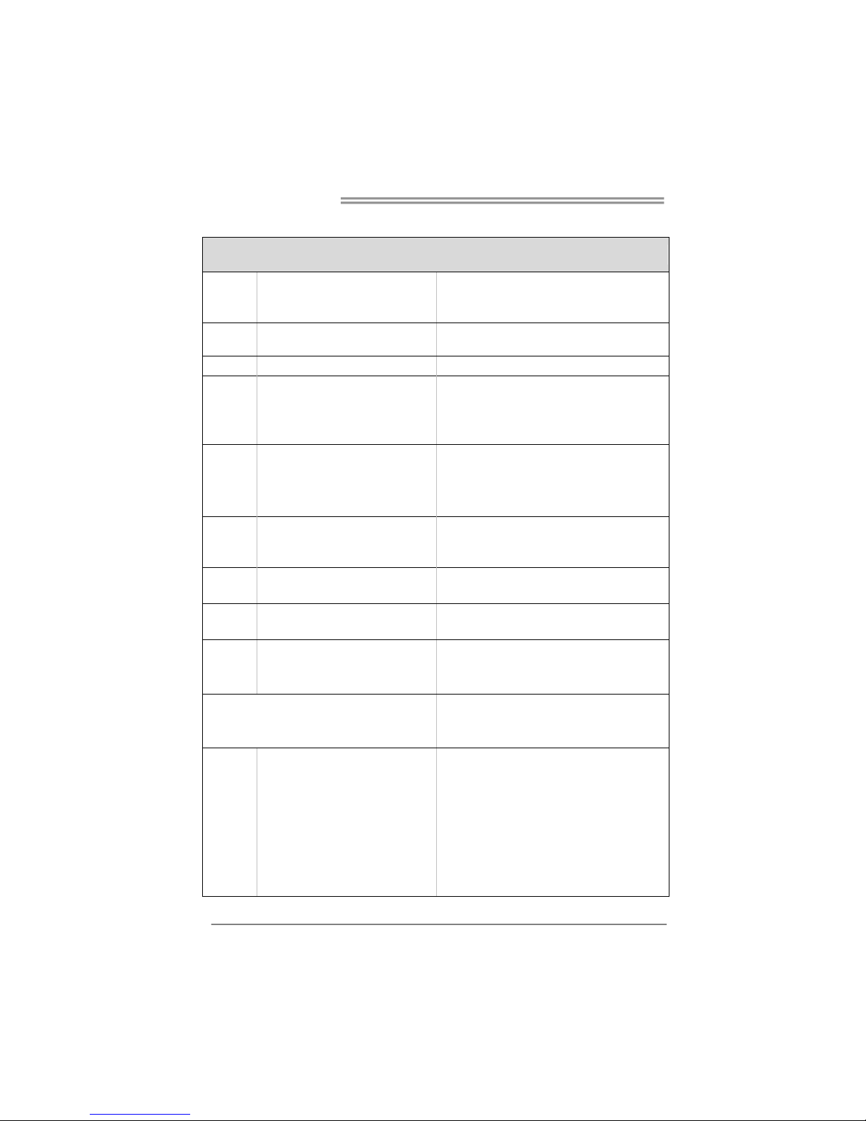
Conector da ventoinha da CPU x1
Alimentação da ventoinha da CPU (com a função Smart
Fan)
Conector da ventoinha do sistema x3 Alimentação da ventoinha do sistema
Conector para detecção da
abertura do chassis x1
Para detectar qualquer intrusão no chassis
Conector para limpeza do CMOS x1
Conector USB x3 Cada conector suporta 2 portas USB no painel frontal
Conector de alimentação x1
(24 pinos)
Conector de alimentação x1
(4 pinos)
Entradas/S
aídas no
painel
traseiro
Teclado P S/ 2 x 1
Rato PS/2 x1
Porta série x1
Porta LAN x1
Porta USB x4
Tomada de áudio x3
Ta ma n ho
da placa
218 mm (L) X 293 mm (A)
Característi
cas
especiais
nTunes da NVIDIA
Suporta as funções RAID 0 / 1 / 0+1
Sistemas
operativos
suportados
Windows 2K / XP
A Biostar reserva-se o direito de adicionar ou remover
suporte para qualquer sistema operativo com ou sem
aviso prévio.
Page 58
Motherboard Manual
56
POLISH
SPEC
Procesor
Socket AM2
AMD Athlon 64 / Athlon 64 FX / Procesory
Althlon 64X2 / Sempron
Architektura AMD 64 umożliwia przetwarzanie 32 i 64
bitowe
Obsługa Hyper Transport oraz Cool’n’Quiet
FSB
Obsługa HyperTransport o szerokości
pasma do 1000 MHz
Chipset
nVIDIA nForce4
Pamięć
główna
Gniazda DDR2 DIMM x 4
Każde gniazdo DIMM obsługuje moduły
256/512MB oraz 1GB DDR2
Maks. wielkość pamięci 4GB
Moduł pamięci DDR2 z trybem podwójnego kanału
Obsługa DDR2 400 / 533 / 667 / 800
Brak obsługi Registered DIMM oraz Non-ECC DIMM
Super I/O
ITE 8712F
Zapewnia najbardziej powszechne funkcje
Super I/O.
Interfejs Low Pin Count
Funkcje kontroli warunków pracy,
Monitor H/W
Kontroler prędkości wentylatora
Funkcja ITE "Smart Guardian"
IDE
Zintegrowany kontroler IDE
Ultra DMA 33 / 66 / 100 / 133 Tryb Bus
Master
obsługa PIO tryb 0~4,
SATA
Zintegrowany kontroler Serial ATA
Transfer danych do 1.5 Gb/s.
Zgodność ze specyfikacją SATA w wersji 1.0.
LAN
Realtek 8201CL PHY
10 / 100 Mb/s oraz automatyczną negocjacją szybkości
Działanie w trybie połowicznego / pełnego dupleksu
Kodek
dźwiękowy
ALC 655 / 658 (opcja)
8 kanałowe wyjście audio
AC’97 w wersji 2.3
Wyjście S/PDIF
Gniazdo PCI x4
Gniazdo PCI Express x16 x1
Gniazda
Gniazdo PCI Express x 1 x2
Złącze napędu dyskietek x1 Każde złącze obsługuje 2 napędy dyskietek
Złącze Port drukarki x1 Każde złącze obsługuje 1 Port drukarki
Złącze IDE x2 Każde złącze obsługuje 2 urządzenia IDE
Złącze SATA x4 Każde złącze obsługuje 1 urządzenie SATA
Złącze panela przedniego x1 Obsługa elementów panela przedniego
Przednie złącze audio x1 Obsługa funkcji audio na panelu przednim
Złącze wejścia CD x1 Obsługa funkcji wejścia audio CD
Złącza
wbudowane
Złącze wyjścia S/PDIF x1 Obsługa funkcji cyfrowego wyjścia audio
Page 59
TForce4 AM2
57
SPEC
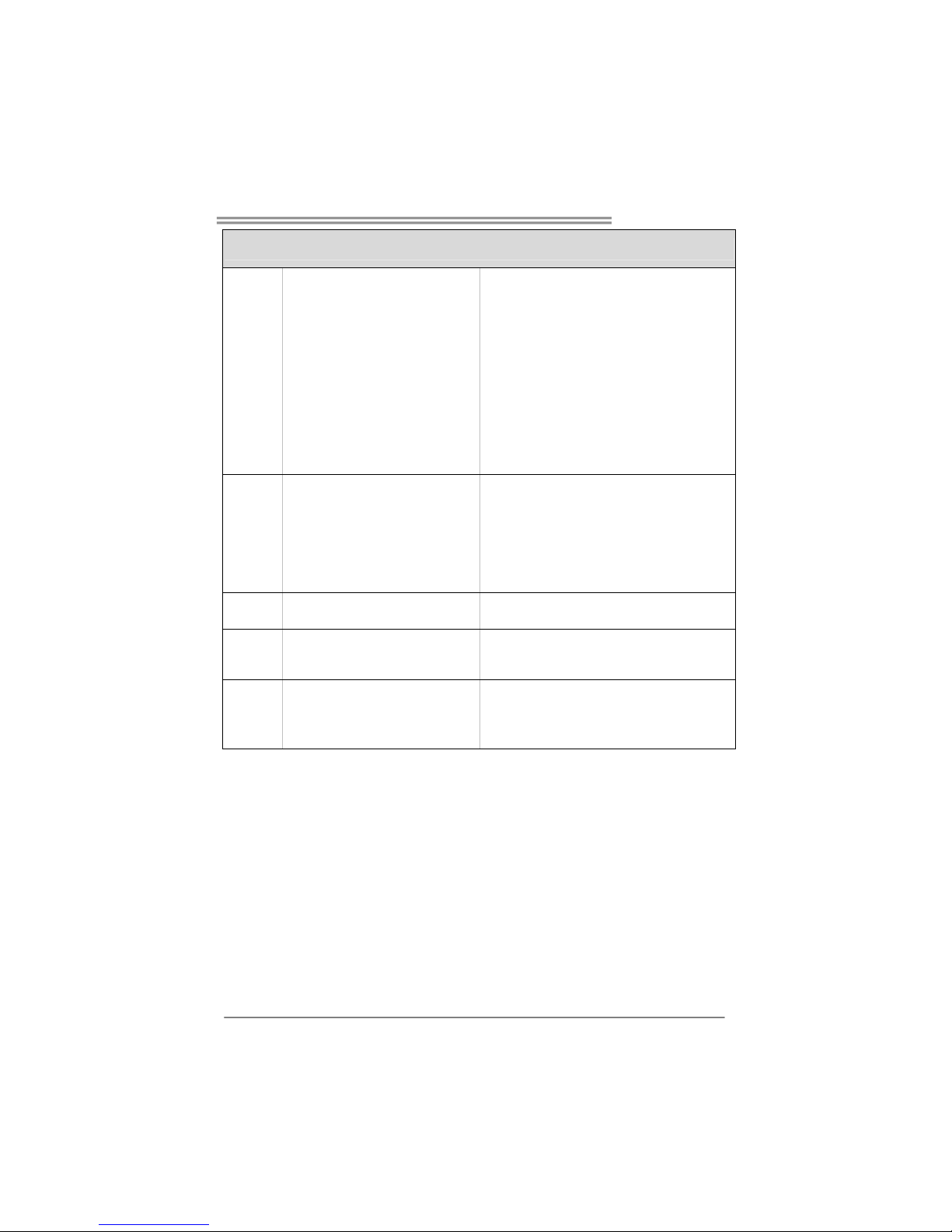
Złącze główkowe wentylatora procesora ... Zasilanie wentylatora procesora (z funkcją Smart Fan)
Złącze główkowe wentylatora
systemowego x3
Zasilanie wentylatora systemowego
Złącze główkowe otwarcia
obudowy (opcja) x1
Do funkcji wykrywania naruszenia obudowy
Złącze główkowe kasowania
CMOS x1
Złącze USB x3
Każde złącze obsługuje 2 porty USB na panelu
przednim
Złącze zasilania (24 pinowe) x1
Złącze zasilania (4 pinowe) x1
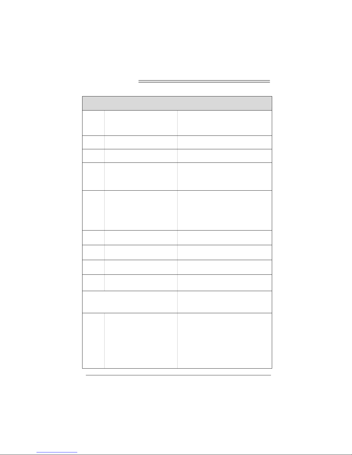
Back Panel
I/O
Klawiatura PS/2 x1
Mysz PS/2 x1
Port szeregowy x1
Port LAN x1
Port USB x4
Gniazdo audio x3
Wymiary
płyty
218mm (S) X 293 mm (W)
Funkcje
specjalne
NVIDIA nTunes.
Obsługa RAID 0 / 1 / 0+1
Obsluga
systemu
operacyjne
go
Windows 2K / XP
Biostar zastrzega sobie prawo dodawania lub
odwoływania obsługi dowolnego systemu
operacyjnego bez powiadomienia.
Page 60
Motherboard Manual
58
RUSSIAN
СПЕЦ.
CPU
(центральн
ый
процессор)
Гнездо AM2
Процессоры AMD Athlon 64 / Athlon 64
FX / Althlon 64X2 / Sempron
Архитектура AMD 64 разрешать обработка данных
на 32 и 64 бит
Поддержка Hyper Transport и Cool’n’Quiet
FSB
Поддержка HyperTransport с
пропускной способностью до 1000 МГц
Набор
микросхем
nVIDIA nForce4
Основная
память
Слоты DDR2 DIMM x 4
Каждый модуль DIMM поддерживает
256/512МБ & 1ГБ DDR2
Максимальная ёмкость памяти 4 ГБ
Модуль памяти с двухканальным режимом DDR2
Поддержка DDR2 400 / 533 / 667 / 800
Не поддерживает зарегистрированные модули
DIMM and Non-ECC DIMM
Super I/O
ITE 8712F
Обеспечивает наиболее используемые
действующие функциональные
возможности Super I/O.
Интерфейс с низким количеством
выводов
Инициативы по охране окружающей среды,
Аппаратный монитор
Регулятор скорости
Функция ITE "Smart Guardian" (Интеллектуальная
защита)
IDE
Встроенное устройство управления
встроенными интерфейсами устройств
Режим "хозяина" шины Ultra DMA 33 / 66 / 100 / 133
Поддержка режима PIO 0~4,
SATA
Встроенное последовательное
устройство управления ATA
скорость передачи данных до 1.5 гигабит/с.
Соответствие спецификации SATA версия 1.0.
Локальная
сеть
Realtek 8201CL PHY
Автоматическое согласование 10 / 100 Мб/с .
Частичная / полная дуплексная способность
Звуковой
кодек
ALC655 / 658 (дополнительно)
Шестиканальный звуковой выход
AC’97 Версия 2.3Вывод S/PDIF
Слот PCI x2
Слот PCI Express x16 x1
Слоты
Слот PCI Express x 1 x1
Разъём НГМД x1
Каждый разъём поддерживает 2 накопителя на
гибких магнитных дисках
Разъём Порт подключения принтера ....
Каждый разъём поддерживает 1 Порт подключения
принтера
Разъём IDE x2
Каждый разъём поддерживает 2 встроенных
интерфейса накопителей
Разъём SATA x4 Каждый разъём поддерживает 1 устройство SATA
Встроенны
й разъём
Разъём на лицевой панели x1 Поддержка устройств на лицевой панели
Page 61

TForce4 AM2
59
СПЕЦ.
Входной звуковой разъём x1 Поддержка звуковых функций на лицевой панели
Разъём ввода для CD x1 Поддержка функции ввода для CD
Разъём вывода для S/PDIF x1 Поддержка вывода цифровой звуковой функции
Контактирующее приспособление
вентилятора центрального процессора..
Источник питания для вентилятора центрального
процессора (с функцией интеллектуального
вентилятора)
Контактирующее приспособление
вентилятора системы x3
Источник питания для вентилятора системы
Шасси открытого контактирующего
приспособления (дополнительно) x1
Для функции обнаружения злоумышленника шасси
Открытое контактирующее
приспособление CMOS x1
USB-разъём x3
Каждый разъём поддерживает 2 USB-порта на
лицевой панели
Разъем питания (24 вывод) x1
Разъем питания (4 вывод) x1
Задняя
панель
средств
ввода-выв
ода
Клавиатура PS/2 x1
Мышь PS/2 x1
Последовательный порт x1
Порт LAN x1
USB-порт x4
Гнездо для подключения
наушников x3
Размер
панели
218 мм (Ш) X 293 мм (В)
Специальн
ые
технически
е
характерис
тики
NVIDIA nTunes
Поддержка RAID 0 / 1 / 0+1
Поддержка
OS
Windows 2K / XP
Biostar сохраняет за собой право добавлять или
удалять средства обеспечения для OS с или без
предварительного уведомления.
Page 62
Motherboard Manual
60
ARABIC
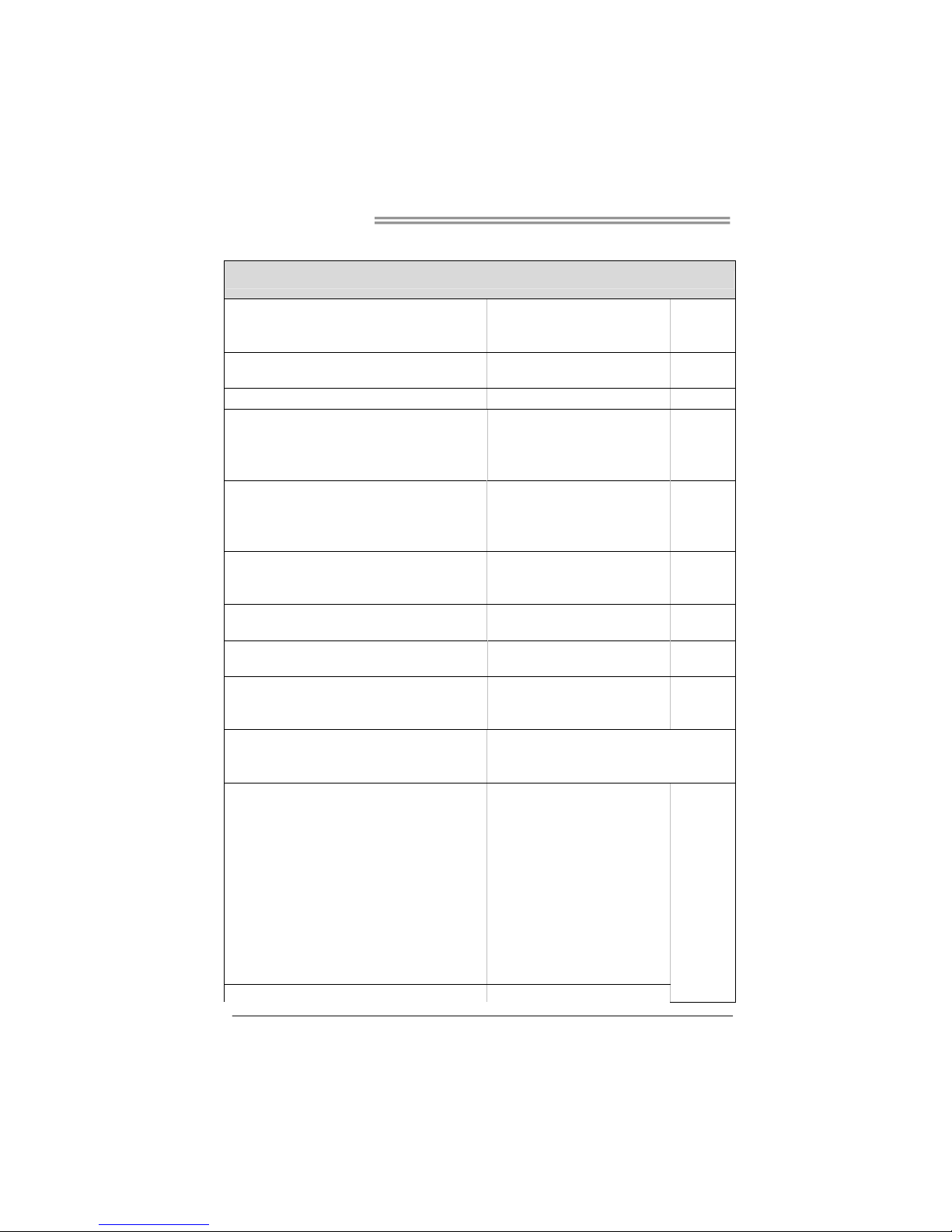
تﺎﻔﺻاﻮﻤﻟا
ﺔﺠﻟﺎﻌﻤﻟا ةﺪﺣو
ﺔﻳﺰآﺮﻤﻟا
ﺲﺒﻘﻡAM2
تﺎﺠﻟﺎﻌﻡAMD Athlon 64 / Athlon 64 FX /
Althlon 64X2 / Sempron
ﺔﻴﻨﻘﺗ ﻦﻜﻤﺗAMD 64 ﺔﻋﺮﺴﺏ ﺔﻴﺏﻮﺳﺎﺤﻟا تﺎﻴﻠﻤﻌﻟا ءاﺮﺝإ 32 و64 ﺖﺏ
ﺔﻴﻨﻘﺗ ﻢﻋﺪﺗHyper Transport و Cool’n’Quiet
ﻲﺒﻥﺎﺠﻟا ﻲﻡﺎﻡﻷا ﻞﻗﺎﻨﻟا
ﻴﻨﻘﺗ ﻢﻋﺪﺗ ﺔ HyperTransport ﻰﻟإ ﻞﺼﻳ ددﺮﺘﺏ 1000
ددﺮﺗ
ﺢﺋاﺮﺸﻟا ﺔﻋﻮﻤﺠﻡ
nVIDIA nForce4
ﺔﻴﺴﻴﺋﺮﻟا ةﺮآاﺬﻟا
ﺔﺤﺘﻓDDR2 DIMM دﺪﻋ4
ﺔﺤﺘﻓ ﻞآ ﻢﻋﺪﺗDIMM عﻮﻥ ﻦﻡ ةﺮآاذ ﻢﻋﺪﺗ DDR2 ﺔﻌﺳ
256/512 و ﺖﻳﺎﺏ ﺎﺠﻴﻡ 1 ﺎﺠﻴﺝﺖﻳﺎﺏ
ىﻮﺼﻗ ةﺮآاذ ﺔﻌﺳ4 ﺖﻳﺎﺏ ﺎﺠﻴﺝ
ةﺮآاذ ةﺪﺣوDDR2 ﻘﻟا ﺔﺝودﺰﻡةﺎﻨ
آاﺬﻟا ﻢﻋﺪﺗ عﻮﻥ ﻦﻡ ةﺮ DDR2 تﺎﻌﺳ 400 / 533 / 667 / 800ﺖﻳﺎﺏ ﺎﺠﻴﻡ
ةﺮآاﺬﻟا ﻖﺋﺎﻗر ﻢﻋﺪﺗ ﻻDIMM ﻊﻡ ﻖﻓاﻮﺘﺗ ﻻ ﻲﺘﻟا ﻚﻠﺗو ﺔﻠﺠﺴﻤﻟا ECC
Super I/O
ITE 8712F
ﺔﻔﻴﻇو ﺮﻓﻮﺗSuper I/O ًﺎﻡ ا ﺪ ﺨ ﺘﺳ ا ﺮﺜآﻷا .
ﺗﻢﻋﺪ ﺔﻴﻨﻘﺗ Low Pin Count Interface
ﺔﺌﻴﺒﻟا ﻲﻓ ﻢﻜﺤﺘﻟا ﻞﺋﺎﺳو:
ﻷا ﺔﻟﺎﺣ ﺔﻓﺮﻌﻤﻟ ﺐﻗاﺮﻡةﺰﻬﺝ
ﺔﺣوﺮﻤﻟا ﺔﻋﺮﺳ ﻲﻓ ﺐﻗاﺮﻡ
ﺔﻔﻴﻇو"Smart Guardian" ﻦﻡ ITE
ﺬﻔﻨﻡIDE
ﻢﻜﺤﺘﻡIDEﻞﻡﺎﻜﺘﻡ
ﺔﻴﻨﻘﺘﺏ ﻞﻗﺎﻥUltra DMA 33 / 66 / 100 / 133
ﻲﺴﻴﺋر ﻊﺿو
ﻊﺿو ﻢﻋدPIO Mode 0~4
SATA
ﻢﻜﺤﺘﻡSerial ATAﻞﻡﺎﻜﺘﻡ
ﻰﻟإ ﻞﺼﺗ تﺎﻋﺮﺴﺏ تﺎﻥﺎﻴﺒﻟا ﻞﻘﻥ1.5 ﺖﺏﺎﺠﻴﺝ/ﺔﻴﻥﺎﺙ.
تﺎﻔﺹاﻮﻤﻟ ﺔﻘﺏﺎﻄﻡSATA ا راﺪﺹﻹ 1.0.
ﺔﻴﻠﺥاد ﺔﻜﺒﺵ
Realtek 8201CL PHY
ﻲﺋﺎﻘﻠﺗ ضوﺎﻔﺗ10/100 ﺖﻳﺎﺏ ﺎﺠﻴﻡ /و ﺔﻴﻥﺎﺙ
ﻞﻡﺎﻜﻟا جودﺰﻤﻟا ﻞﻘﻨﻟا ﺔﻴﻥﺎﻜﻡإ/ﻲﻔﺼﻨﻟا
تﻮﺼﻟا ﻚﻳدﻮآ
ALC 655 / 658 )يرﺎﻴﺘﺥا(
6تﻮﺼﻟا جﺮﺨﻟ تاﻮﻨﻗ
راﺪﺹﻹا2.3 ﻦﻡ AC’97
جﺮﺥ S/PDIF
ﺔﺤﺘﻓPCI دﺪﻋ4
ﺔﺤﺘﻓx16 PCI Express دﺪﻋ1
تﺎﺤﺘﻔﻟا
ﺔﺤﺘﻓPCI Express x 1 دﺪﻋ2
ﺔﻥﺮﻡ صاﺮﻗأ كﺮﺤﻡ ﺬﻔﻨﻡ دﺪﻋ1 ﺔﻥﺮﻤﻟا صاﺮﻗﻸﻟ ﻦﻴآﺮﺤﻡ ﻢﻋﺪﻳ
ﺔﻌﺏﺎﻃ ﺬﻔﻨﻡ دﺪﻋ1
ﺬﻔﻨﻡIDE دﺪﻋ2 ةﺰﻬﺝأ ﻦﻡ ﻦﻴﻨﺙا ﺬﻔﻨﻡ ﻞآ ﻢﻋﺪﻳIDE
ﺬﻔﻨﻡSATA دﺪﻋ4 ةﺰﻬﺝأ ﻦﻡ ﺪﺣاو ﺬﻔﻨﻡ ﻞآ ﻢﻋﺪﻳSATA
ﺔﻴﻡﺎﻡﻷا ﺔﺣﻮﻠﻟا ﺬﻔﻨﻡ دﺪﻋ1 ﺔﻴﻡﺎﻡﻷا ﺔﺣﻮﻠﻟا تاﺰﻴﻬﺠﺗ ﻢﻋﺪﻳ
ﻲﻡﺎﻡﻷا تﻮﺼﻟا ﺬﻔﻨﻡ دﺪﻋ1 ﺔﻴﻡﺎﻡﻷا ﺔﺣﻮﻠﻟﺎﺏ تﻮﺼﻟا ﺔﻔﻴﻇو ﻢﻋﺪﻳ
ﺬﻔﻨﻡCD-IN دﺪﻋ1 ﺞﻡﺪﻤﻟا صﺮﻘﻟا تﻮﺹ ﻞﺥد ﺔﻔﻴﻇو ﻢﻋﺪﻳ
جﺮﺥ ﺬﻔﻨﻡS/PDIF دﺪﻋ1 ﻲﻤﻗﺮﻟا تﻮﺼﻟا جﺮﺥ ﺔﻔﻴﻇو ﻢﻋﺪﻳ
ﺔﻳﺰآﺮﻤﻟا ﺔﺠﻟﺎﻌﻤﻟا ةﺪﺣو ﺔﺣوﺮﻡ ﺔﻠﺹو دﺪﻋ1 ﺔﻗﺎﻄﻟا ﻞﻴﺹﻮﺘﻟ ﺔﺠﻟﺎﻌﻤﻟا ةﺪﺣو ﺔﺣوﺮﻤﻟ) ﺔﻔﻴﻇو ﻊﻡ Smart Fan(
مﺎﻈﻨﻟا ﺔﺣوﺮﻡ ﺔﻠﺹو دﺪﻋ3 مﺎﻈﻨﻟا ﺔﺣوﺮﻤﻟ ﺔﻗﺎﻄﻟا ﻞﻴﺹﻮﺘﻟ
ﻞﻜﻴﻬﻟا ﺢﺘﻓ ﺔﻠﺹو)يرﺎﻴﺘﺥا( دﺪﻋ1 ﻞﻜﻴﻬﻟا قاﺮﺘﺥا ﻦﻋ ﻒﺸﻜﻠﻟ
ﺢﻄﺳ ﻰﻠﻋ ﺬﻓﺎﻨﻤﻟا
ﺔﺣﻮﻠﻟا
ﺢﺴﻡ ﺔﻠﺹوCMOS دﺪﻋ1
Page 63
TForce4 AM2
61
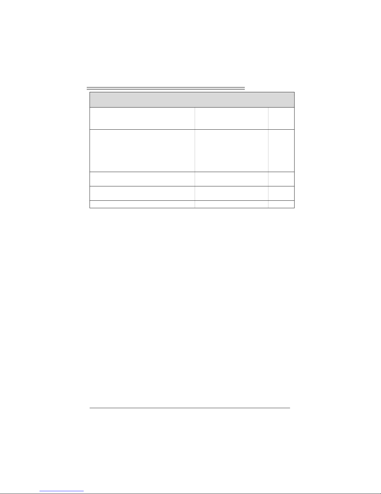
تﺎﻔﺻاﻮﻤﻟا
ﺬﻔﻨﻡUSB دﺪﻋ3 ﻲﺘﺤﺘﻓ ﺬﻔﻨﻡ ﻞآ ﻢﻋﺪﻳUSBﺔﻴﻡﺎﻡﻷا ﺔﺣﻮﻠﻟﺎﺏ
ﺔﻗﺎﻄﻟا ﻞﻴﺹﻮﺗ ﺬﻔﻨﻡ)24دسﻮﺏ( دﺪﻋ1
ﺔﻗﺎﻄﻟا ﻞﻴﺹﻮﺗ ﺬﻔﻨﻡ)4ﺲﻴﺏﺎﺏد( دﺪﻋ1
ﻞﺥد ﺬﻓﺎﻨﻡ/ جﺮﺥ
ﺔﻴﻔﻠﺨﻟا ﺔﺣﻮﻠﻟا
ﺢﻴﺗﺎﻔﻡ ﺔﺣﻮﻟPS/2 دﺪﻋ1
سوﺎﻡ PS/2 دﺪﻋ1
ﻲﻠﺴﻠﺴﺗ ﺬﻔﻨﻡ دﺪﻋ1
ﺔﻴﻠﺤﻡ لﺎﺼﺗا ﺔﻜﺒﺵ ﺬﻔﻨﻡ دﺪﻋ1
ﺬﻓﺎﻨﻡUSB دﺪﻋ4
تﻮﺹ ﺲﺒﻘﻡ دﺪﻋ3
ﺔﺹﺎﺥ ﺎﻳاﺰﻡ
NVIDIA nTunes
ﺔﻴﻨﻘﺗ ﻢﻋﺪﺗRAID 0 / 1 / 0+1
ﺔﺣﻮﻠﻟا ﻢﺠﺣ
218 ﻢﻡ)ضﺮﻋ (X 293 ﻢﻡ)عﺎﻔﺗرا(
ﻞﻴﻐﺸﺘﻟا ﺔﻤﻈﻥأ ﻢﻋد
Windows 2K / XP
ﻆﻔﺘﺤﺗBiostar رﺎﻄﺥإ نوﺪﺏ وأ رﺎﻄﺥﺈﺏ ﻞﻴﻐﺸﺗ مﺎﻈﻥ يﻷ ﻢﻋﺪﻟا ﺔﻟازإ وأ ﺔﻓﺎﺿإ ﻲﻓ ﺎﻬﻘﺤﺏ .
Page 64
Motherboard Manual
62
JAPANESE
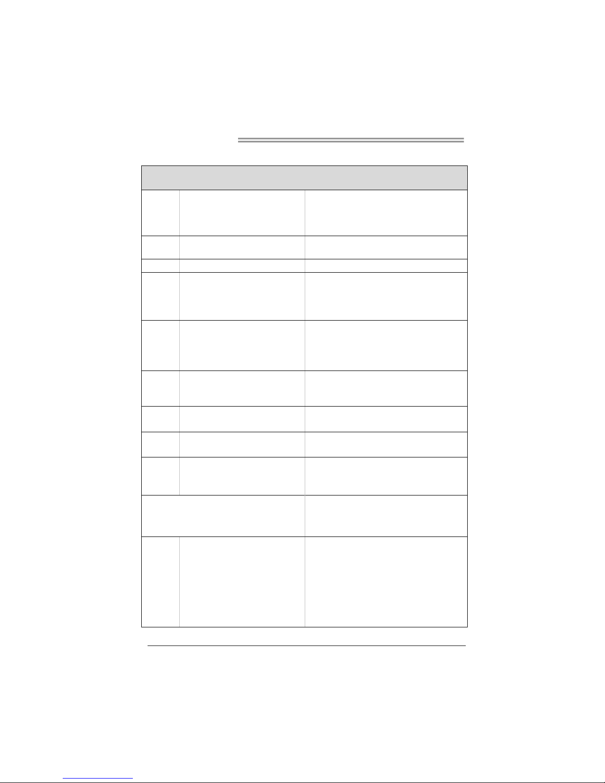
仕様
CPU
Socket AM2
AMD Athlon 64 / Athlon 64 FX / Althlon
64X2 / Sempron プロセッサ
AMD 64アーキテクチャでは、32ビットと64ビット計算が可
能です
ハイパートランスポートとクールアンドクワイアットをサポ
ートします
FSB
1000 MHz のバンド幅までハイパートランス
ポートをサポートします
チップセット
nVIDIA nForce4
メインメモリ
DDR2 DIMMスロット x 4
各DIMMは 256/512MB & 1GB DDR2をサポ
ート
最大メモリ容量4GB
デュアル チャンネルモードDDR2メモリモジュール
DDR2 400 / 533 / 667 / 800をサポート
登録済みDIMMと非ECC DIMMはサポートされません
Super I/O
ITE 8712F
もっとも一般に使用されるレガシーSuper I/O
機能を採用しています。
低ピンカウントインターフェイス
環境コントロールイニシアチブ、
H/Wモニター
ファン速度コントローラ/ モニター
ITEの「スマートガーディアン」機能
IDE
統合IDEコントローラ
Ultra DMA 33 / 66 / 100 / 133バスマスタモ
ード
PIO Mode 0~4のサポート、
SATA
統合シリアルATAコントローラ
最高 1.5 Gb/秒のデータ転送速度
SATAバージョン1.0仕様に準拠。
LAN
Realtek 8201CL PHY
10 / 100 Mb/秒のオートネゴシエーション
半/全二重機能
サウンド
Codec
ALC 655 / 658 (オプション)
6チャンネルオーディオアウト
AC’97バージョン2.3
S/PDIF アウト
PCIスロット x4
PCI Express x16スロット x1
スロット
PCI Express x 1スロット x2
フロッピーコネクタ x1 各コネクタは2つのフロッピードライブをサポートします
プリンタポートコネクタ x1 各コネクタは1つのプリンタポートをサポートします
IDEコネクタ x2 各コネクタは2つのIDEデバイスをサポートします
SATAコネクタ x4 各コネクタは1つのSATAデバイスをサポートします
フロントパネルコネクタ x1 フロントパネル機能をサポートします
フロントオーディオコネクタ x1 フロントパネルオーディオ機能をサポートします
オンボードコ
ネクタ
CDインコネクタ x1 CDオーディオイン機能をサポートし ます
Page 65
TForce4 AM2
63
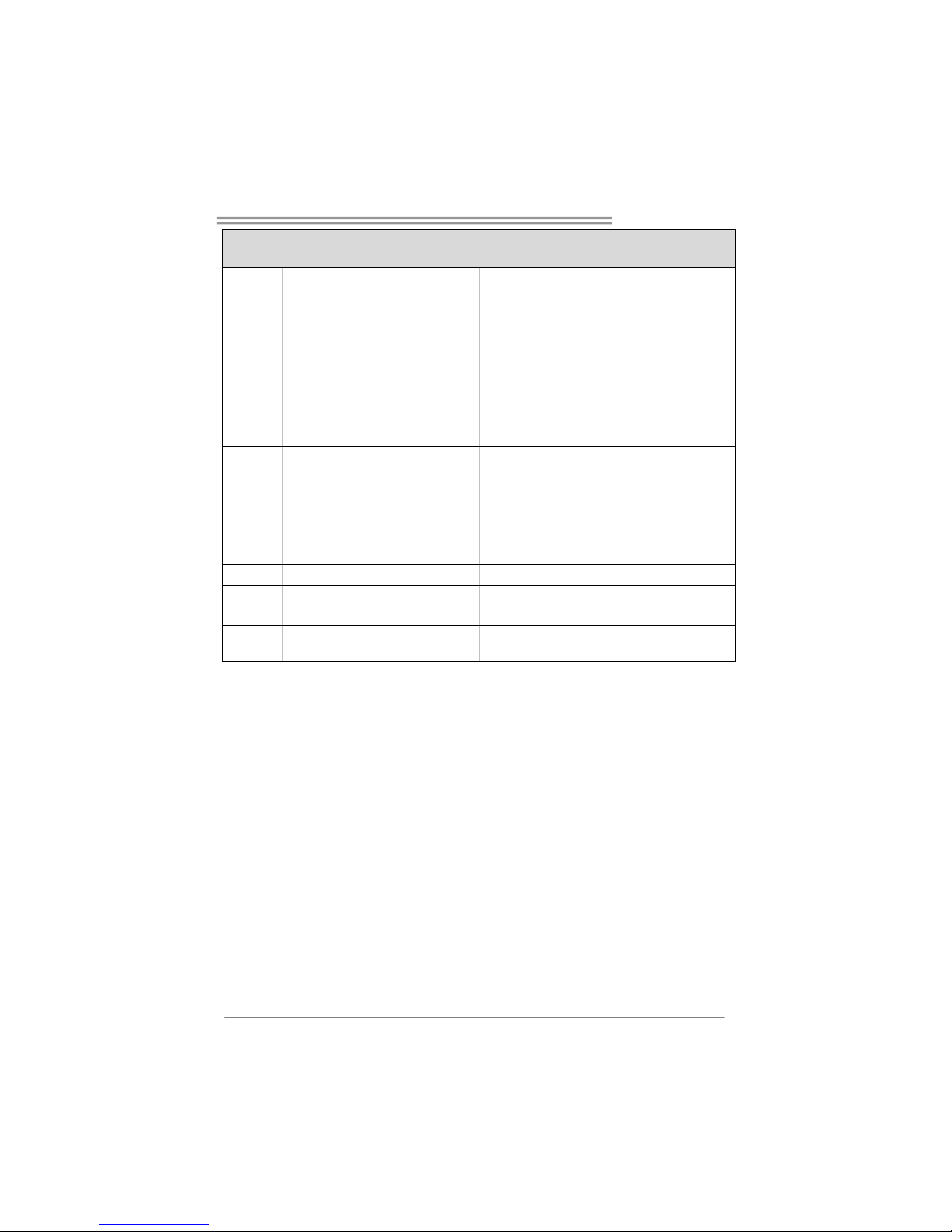
仕様
S/PDIFアウトコネクタ x1 デジタルオーディオアウト機能をサポートします
CPUファンヘッダ x1 CPUファン電源装置(スマートファン機能を搭載)
システムファンヘッダ x3 システムファン電源装置
シャーシオープンヘッダ(オプション) x1 シャーシ侵入検 出機能
CMOSクリアヘッダ x1
USBコネクタ x3
各コネクタは2つのフロントパネルUSBポートをサポートし
ます
電源コネクタ(24ピン) x1
電源コネクタ(4ピン) x1
背面パネル
I/O
PS/2キーボード x1
PS/2マウス x1
シリアルポート x1
LANポート x1
USBポート x4
オーディオジャック x3
ボードサイズ 218 mm (幅) X 293 mm (高さ)
特殊機能
NVIDIA nTunes
RAID 0 / 1 / 0+1 のサポート
OSサポート Windows 2K / XP
Biostarは事前のサポートなしにOSサポートを追加または削
除する権利を留保します。
 Loading...