

Page 1

TF520 A2+/TF560 A2+ Setup Manual
FCC Information and Copyright
This equipment has been tested and found to comply with the limits of a Class
B digital device, pursuant to Part 15 of the FCC Rules. These limits are designed
to provide reasonable protection against harmful interference in a residential
installation. This equipment ge nerates, uses, and can radiate radio frequency
energy and, if not i nstalled and used in accordance with the instructions, may
cause harmful interference to radio communications. There is no guarantee
that interference will not occur in a particular installation.
The vendor makes no representations or warranties with respect to the
contents here and specially disclaims any implied warranties of merchantability
or fitness for any purpose. Further the vendor reserves the right to revise this
publication and to make changes to the contents here without obligation to
notify any party beforehand.
Duplication of this publication, in part or in whole, is not allowed without first
obtaining the vendor’s approval in writing.
The content of this user’s manual is subject to be changed without notice and
we will not be responsible for any mistakes found in this user’s manual. All the
brand and product names are trademarks of their respective companies.
Page 2

Table of Contents
Chapter 1: Introduction ........................................ 1
1.1 Before You Start ................................................................................ 1
1.2 Package Checklist............................................................................. 1
1.3 Motherboard Features...................................................................... 2
1.4 Rear Panel Connectors (Ver 5.x)..................................................... 4
1.5 Rear Panel Conne ctors (Ver 6.x)..................................................... 4
1.6 Motherboard Layout......................................................................... 5
Chapter 2: Hardware Installation........................... 6
2.1 Installing Central Processing Unit (CPU)....................................... 6
2.2 FAN Headers...................................................................................... 8
2.3 Installing System Memory ................................................................ 9
2.4 Connectors and Slots....................................................................... 11
Chapter 3: Headers & Jumpers Setup ................... 13
3.1 How to Setup Jumpers .................................................................... 13
3.2 Detail Settings.................................................................................. 13
Chapter 4: NVIDIA RAID Functions...................... 20
4.1 Operation System............................................................................ 20
4.2 Raid Arrays...................................................................................... 20
4.3 How RAID Works............................................................................. 20
Chapter 5: OverClock Quick Guide ....................... 24
5.1 T-Power Introduction...................................................................... 24
5.2 T-Power BIOS Feature.................................................................... 25
5.3 T-Power Windows Feature ............................................................ 33
Chapter 6: Useful Help......................................... 38
6.1 Driver Installation Note.................................................................. 38
6.2 Award BIOS Beep Code.................................................................. 39
6.3 Extra Information............................................................................ 39
6.4 Troubleshooting............................................................................... 41
Appendencies: SPEC In Other Language .............. 42
German.................................................................................................................. 42
France .................................................................................................................... 44
Ita lian..................................................................................................................... 46
Spanish ................................................................................................................... 48
Portugue se ............................................................................................................ 50
Polish...................................................................................................................... 52
Russian ................................................................................................................... 54
Arabic..................................................................................................................... 56
Japanese ................................................................................................................ 58
Page 3

TF520 A2+/TF560 A2+
1
CHAPTER 1: INTRODUCTION
1.1 B
EFORE YOU START
Thank you for choosing our product. Before you start installing the
motherboard, please make sure you follow the instructions below:
Prepare a dry and stable working environment with
sufficient lighting.
Always disconnect the computer from power outlet
before operation.
Before you take the motherboard out from anti-static
bag, ground yourself properly by touching any safely
grounded appliance, or use grounded wrist strap to
remove the static charge.
Avoid touching the components on motherboard or the
rear side of the board unless necessary. Hold the board
on the edge, do not try to bend or flex the board.
Do not leave any unfastened small parts inside the
case after installation. Loose parts will cause short
circuits which may damage the equipment.
Keep the computer from dangerous area, such as heat
source, humid air and water.
1.2 PACKAGE CHECKLIST
HDD Cable X 1
Serial ATA Cable X 2
Rear I/O Panel for ATX Case X 1
User’s Manual X 1
Fully Setup Driver CD X 1
FDD Cable X 1 (optional)
USB 2.0 Cable X1 (optional)
S/PDIF out Cable X 1 (optional)
Serial ATA Power Cable X 1 (optional)
Page 4
Motherboard Manual
2
1.3 MOTHERBOARD FEATURES
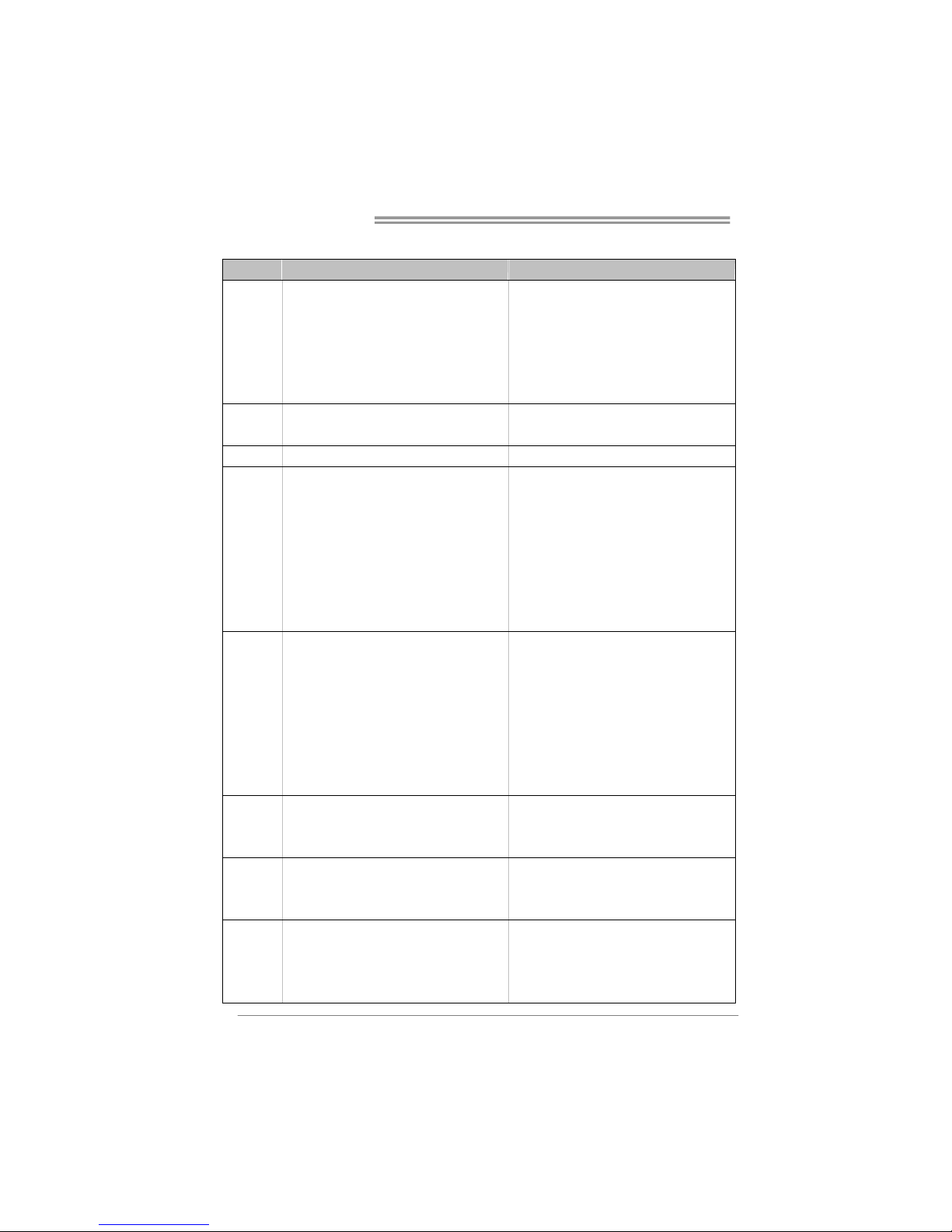
TF520 A2+ TF560 A2+
CPU
Socket AM2 / A M2+ (By B IOS update)
AMD Athlon 64 / Athlon 64 x2 / Sempron
processors
AMD 64 Architecture enables 32 and 64 b it
computing
Supports Hyper Transport and Cool=n=Quiet
Socket AM2 / A M2+ (By B IOS update)
AMD Athlon 64 / Athlon 64 x2 / Sempron
processors
AMD 64 Architecture enables 32 and 64 b it
computing
Supports Hyper Transport and Cool=n=Quiet
FSB
Support up to 1 GHz Bandwidth
Support HyperTransport
Support up to 1 GHz Bandwidth
Support HyperTransport
Chipset nVIDIA nForce 520 nVIDIA nForce 560
Super I/O
ITE 8716F
Prov ides the most common ly used leg ac y Super
I/O functionality.
Low Pin Count Interface
En v ironm en t Cont r ol in it iatives ,
H/W Mon ito r
Fan Sp eed Controller
ITE's "S mart Guard ian" function
ITE 8716F
Prov ides the most common ly used lega cy Supe r
I/O functionality.
Low Pin Count Interface
En v ironm en t Cont r ol in it iatives ,
H/W Mon ito r
Fan Sp eed Controller
ITE's "S mart Guard ian" function
Main
Memory
DIMM Slots x 4
Each DIMM supports 256/512MB & 1GB/2GB
DDR2
Max Memory Capicity 8GB
Dual Channel Mode DDR2 me mory mo du le
Supports DDR2 533 / 667 / 800
Register ed DIMM and ECC D IMM is not
supported
DIMM Slots x 4
Each DIMM supports 256/512MB & 1GB/2GB
DDR2
Max Memory Capicity 8GB
Dual Channel Mode DDR2 me mory mo du le
Supports DDR2 533 / 667 / 800
Register ed DIMM and ECC D IMM is not
supported
IDE
Int egr ated ID E Contro ller
Ultra DMA 33 / 66 / 100 / 133 Bus Master Mode
supports PIO Mode 0~4.
Int egr ated ID E Contro ller
Ultra DMA 33 / 66 / 100 / 133 Bus Master Mode
supports PIO Mode 0~4.
SATA II
Integrated Serial ATA Controller
Data transfer rates up to 3 Gb/s.
SATA Version 2 .0 s pec ific at ion co mpliant .
Integrated Serial ATA Controller
Data transfer rates up to 3 Gb/s.
SATA Version 2 .0 s pec ific at ion co mpliant .
LAN
Realtek RTL 8110SC / 8100C (optional)
10 / 100 Mb/s / 1Gb/s auto negot iation (Gigabit
bandwidth is for RTL 8110SC only)
Half / Full duplex capability
Realtek RTL 8110SC / 8100C (optional)
10 / 100 Mb/s / 1Gb/s auto negot iation (Gigabit
bandwidth is for RTL 8110SC only)
Half / Full duplex capability
Page 5
TF520 A2+/TF560 A2+
3
TF520 A2+ TF560 A2+
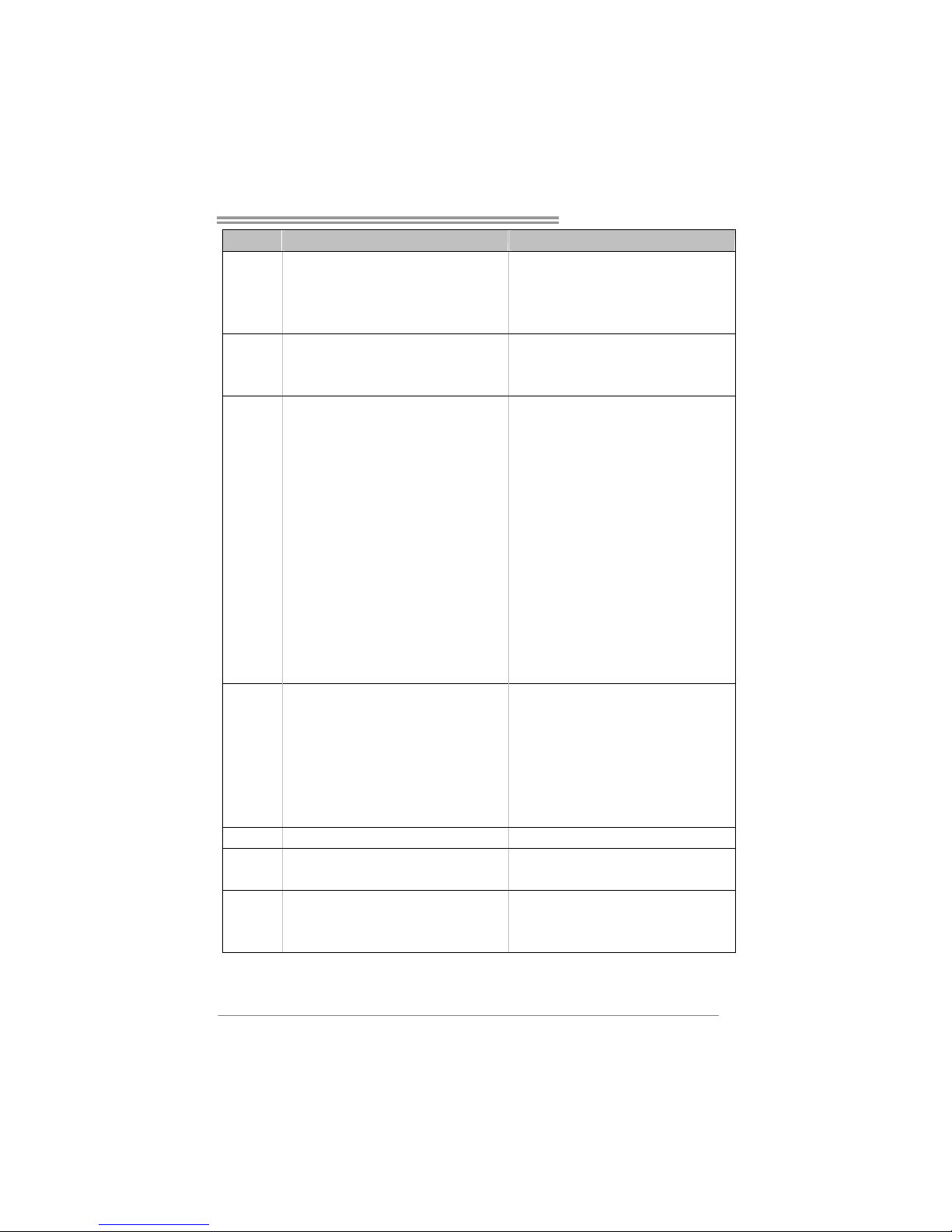
Sound
ALC888 (Ver 5.x) / ALC662 (Ver 6.x)
7.1 channels audio out (ALC888)
5.1 channels audio out (ALC662)
HD Aud io
ALC888 (Ver 5.x) / ALC662 (Ver 6.x)
7.1 channels audio out (ALC888)
5.1 channels audio out (ALC662)
HD Aud io
PCI slot x3 PCI slot x3
PCI Express x16 slot x1 PCI Express x16 slot x1
Slots
PCI Express x 1 slot x2 PCI Express x 1 slot x2
Floppy connect or x1 Floppy connector x1
Printer Port conne ctor x1 Printer Port connect or x1
IDE Conn ector x1 ID E Co nnecto r x1
SATA Connector x4 SATA Connector x4
Front Panel Connector x1 Front Panel Connector x1
Front Audio Connector x1 Front Audio Connector x1
CD-in Connector x1 CD-in Connector x1
S/PDIF out connector x1 S/PDIF out connector x1
CPU Fan header x1 CPU Fan header x1
System Fan head er x2 System Fan head er x2
CMOS clear header x1 CMOS clear header x1
USB co nnector x2 USB connector x 2
Power Connector (24pin) x1 Power Connector (24p in) x1
On Board
Connector
Power Connector (4pin) x2 Power Connector (4pin) x2
Back Panel
I/O
PS/2 Keybo ard x 1
PS/2 Mous e x1
Serial Port x1
LAN port x1
USB Port x6
Audio Jack (Ver 5.x) x6
Audio Jack (Ver 6.x) x3
PS/2 Keybo ard x 1
PS/2 Mous e x1
Serial Port x1
LAN port x1
USB Port x6
Audio Jack (Ver 5.x) x6
Audio Jack (Ver 6.x) x3
Board Size 244 mm (W) x 305 mm (L) 244 mm (W) x 305 mm (L)
Special
Features
NVIDIA nTunes
RAID 0 / 1 / 0+1 support
NVIDIA nTunes
RAID 0 / 1 / 0+1 / 5 support
OS Support
Windows 2K / XP / V ISTA
Biostar Reserves the right to add or remove
support for any OS With or without notice.
Windows 2K / XP / V ISTA
Biostar Reserves the right to add or remove
support for any OS With or without notice.
Page 6
Motherboard Manual
4
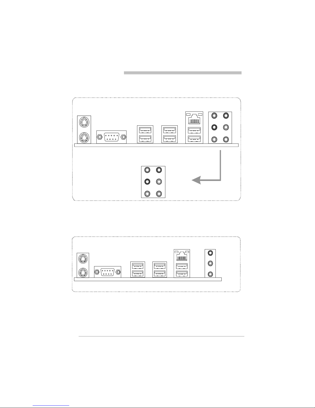
1.4 REAR PANEL CONNECTORS (VER 5.X)
PS/2
Mouse
PS/2
Keyboard
COM1 USB X2USBX2
LAN
Line In
Line Out
Mic In
Center
Rear
Side
USBX2
1.5 REAR PANEL CONNECTORS (VER 6.X)
PS/2
Mou se
PS/ 2
Keybo ard
COM1 USB X2USB X2
LAN
USB X2
Line In/
Surroun d
Line Out
Mic In 1/
Bass/ Center
Page 7
TF520 A2+/TF560 A2+
5
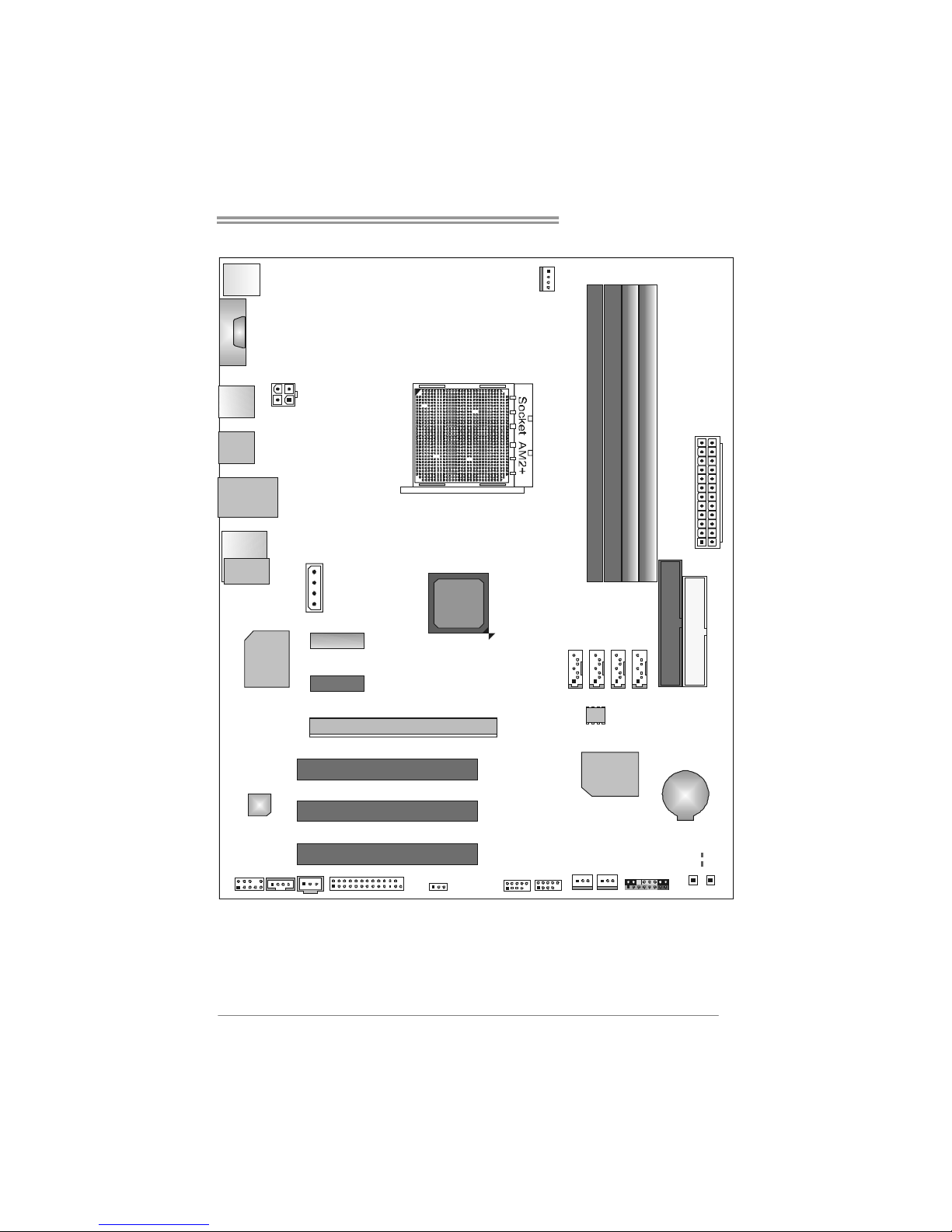
1.6 MOTHERBOARD LAYOUT
JKBMS1
JUSB2
AUD IO 2
(for Ver 5 .x)
PEX1_1
FDD1
BAT1
JCOM1
JCDIN1
Codec
JSPDIF_OUT
JATXPWR2
JPRNT1
PCI1
LAN
JUSB3 JUSB4
DIMMA1
JCMOS1
JPANEL1
IDE1
JATXPWR1
JCFAN1
DIMMB1
DIMMB2
DIMMA2
PEX1_2
PCI3
PCI2
nForce
520/560
SATA4
JAUDIOF1
PWRSW1RSTSW1
JUSBLAN1
JSFA N1
SATA3
SATA2
SATA1
PEX16_1
LED_D1
LED_D2
JATXPWR3
JUSB1
JAUDIO1
(for Ver 6. x)
JSFAN2
SUPER I/O
BIOS
Note: ■ represents the 1st pin.
Page 8
Motherboard Manual
6
CHAPTER 2: HARDWARE INSTALLATION
2.1 I
NSTALLING CENTRAL PROCESSING UNIT (CPU)
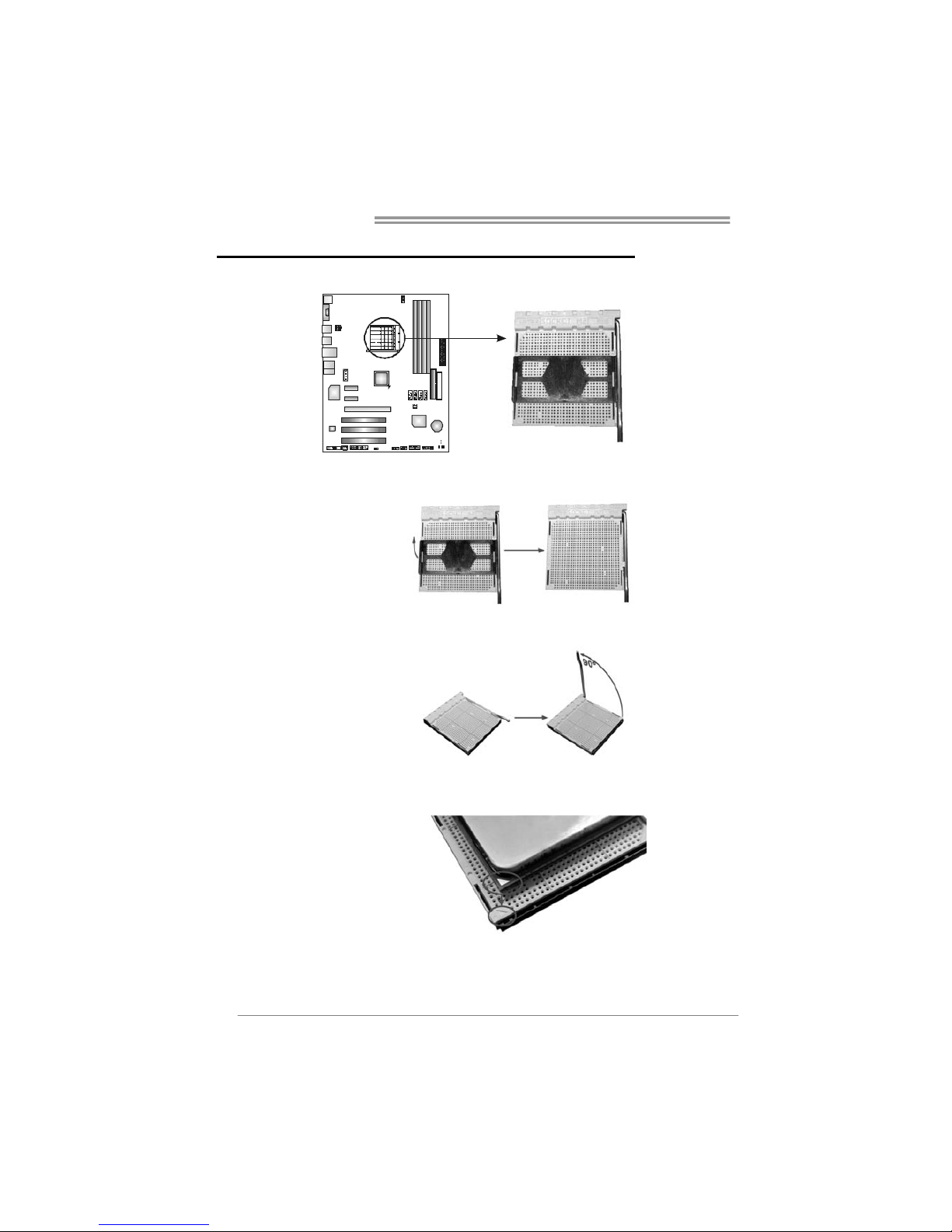
Step 1: Remove the socket protection cap.
Step 2: Pull the lever toward direction A from the socket and then raise the
lever up to a 90-degree angle.
Step 3: Look for the white triangle on socket, and the gold triangle on
CPU should point forwards this white triangle. The CPU will fit
only in the correct orientation.
Page 9
TF520 A2+/TF560 A2+
7
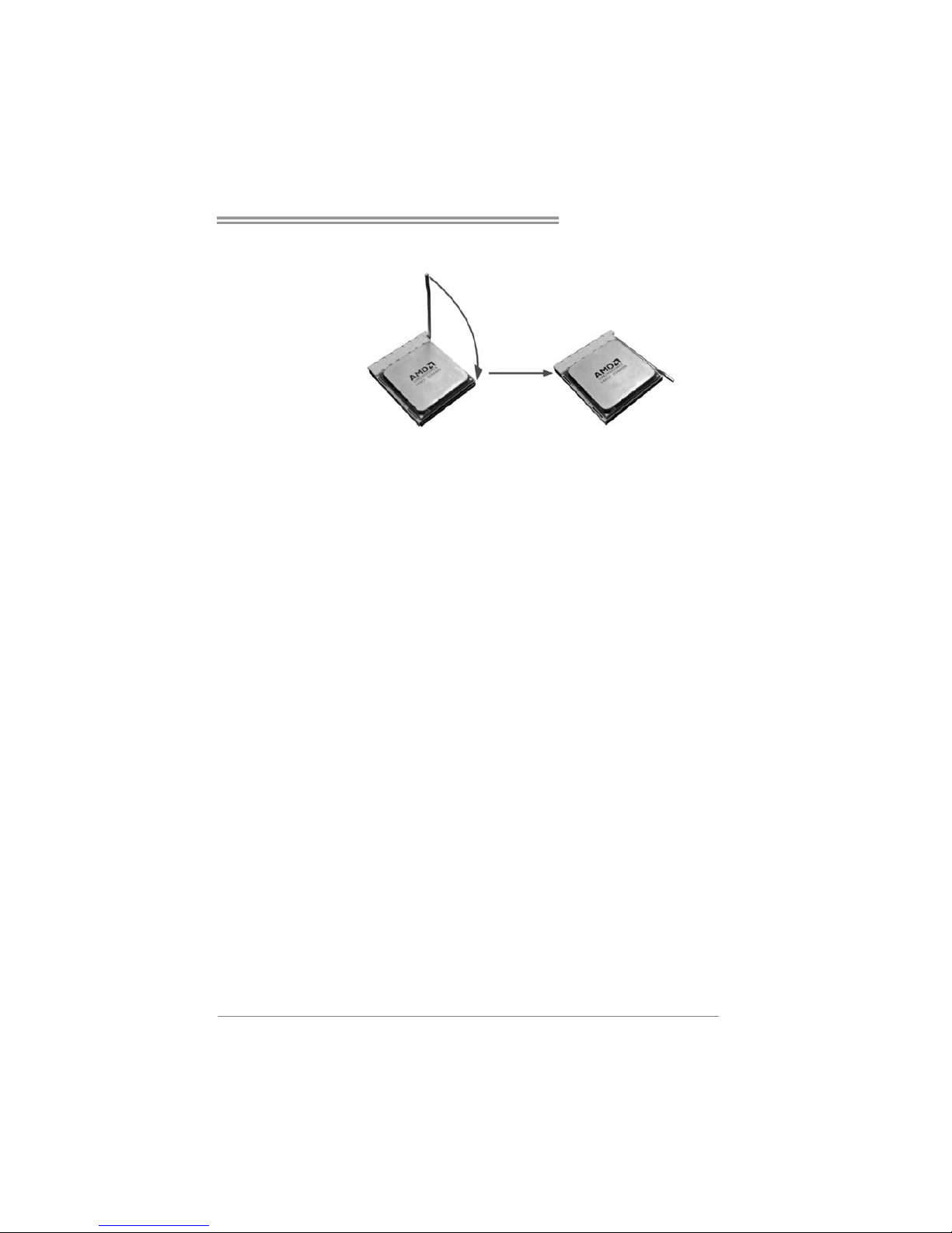
Step 4: Hold the CPU down firmly, and then close the lever toward direct
B to complete the installation.
Step 5: Put the CPU Fan on the CPU and buckle it. Connect the CPU
FAN power cable to the JCFAN1. This completes the installation.
Page 10
Motherboard Manual
8
2.2 FAN HEADERS
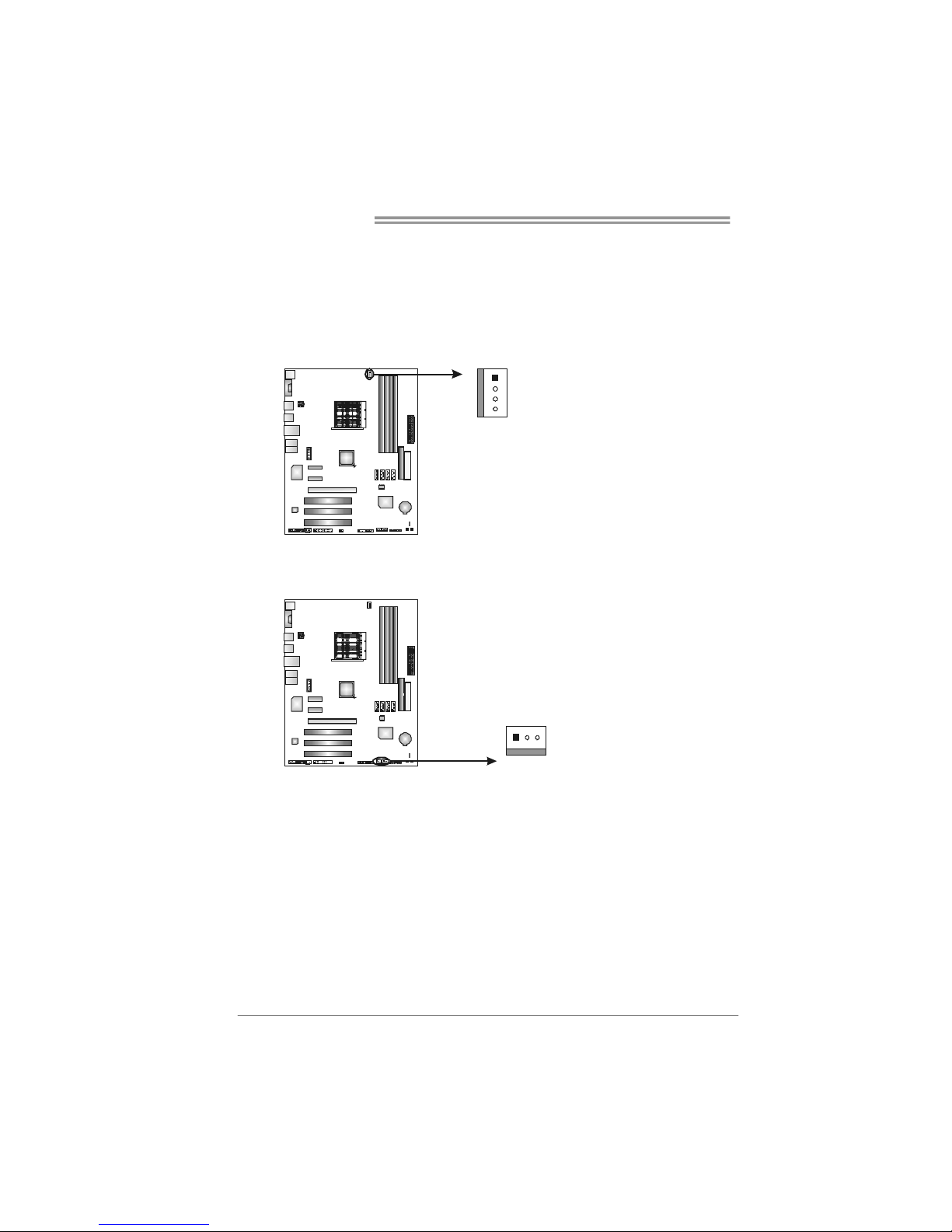
These fan headers support cooling-fans built in the computer. The fan
cable and connector may be different according to the fan manufacturer.
Connect the fan cable to the connector while matching the black wire to
pin#1.
JCFAN1: CPU Fan Header
Pin
Assignment
1 Ground
2 +12V
3
FAN RPM r at e
sense
1
4
4 Smart Fan
Control (By Fan)
JSFAN1/JSFAN2: System Fan Headers
Pin Assignment
1 Ground
2 +12V
13
JSFAN1 JSFAN2
3
FAN RPM
rate sense
Note:
The JCFAN1, JSFAN1, and JSFAN2 support 4-pin and 3-pin head connector. When
connecting with wires onto connectors, please note that the red wire is the positive and
should be co nnected to pin#2, and the black wire is Ground and should be connected to
GND.
Page 11
TF520 A2+/TF560 A2+
9
2.3 INSTALLING SYSTEM MEMORY
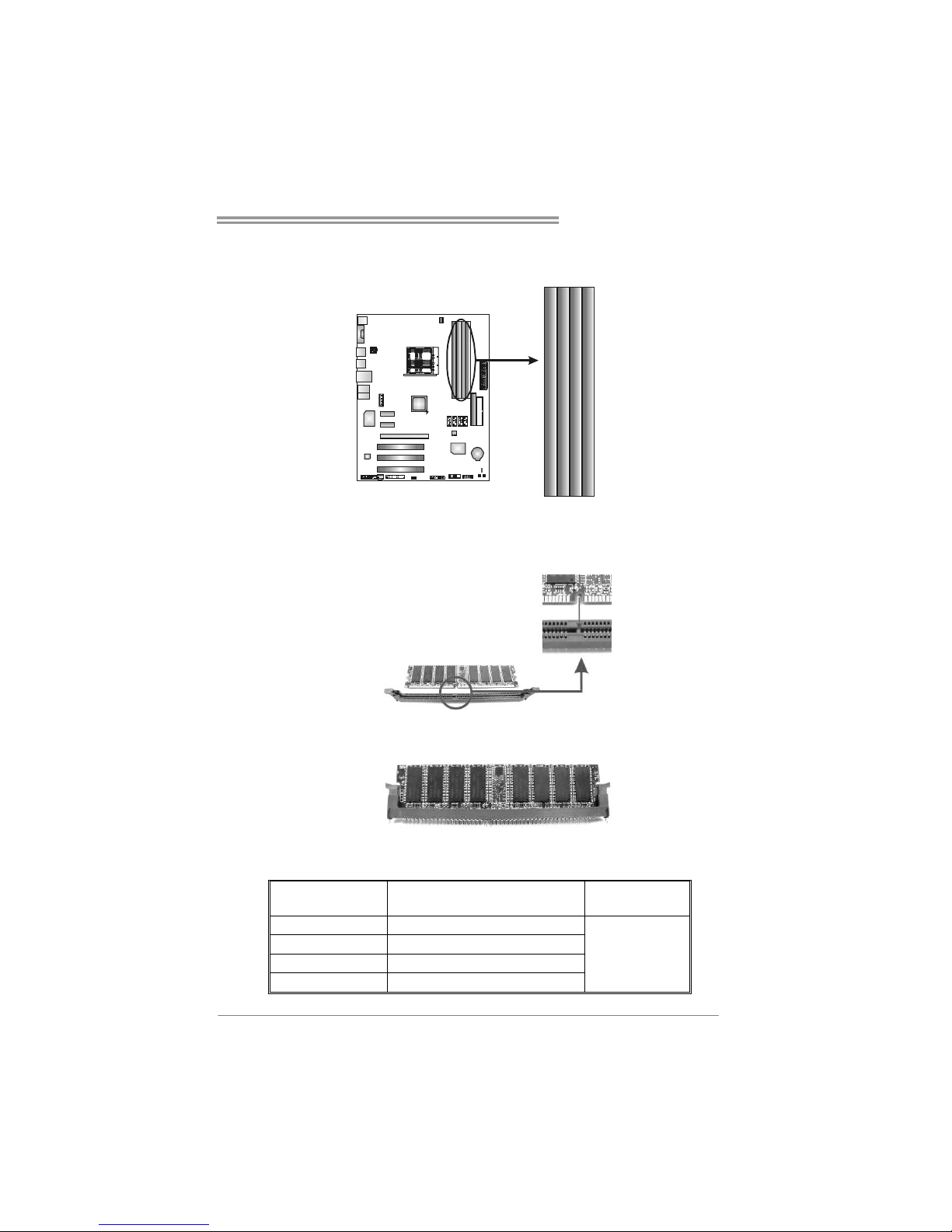
A. Memory Modules
DIMMA1
DIMMB1
DIMMB2
DIMMA2
1. Unlock a DIMM slot by pressing the retaining clips outward. Align a
DIMM on the slot such that the notch on the DIMM matches the
break on the Slot.
2. Insert the DIMM vertically and firmly into the slot until the retaining
chip snap back in place and the DIMM is properly seated.
B. Memory Capacity
DIMM Socket
Location
DDR2 Module
Total Memory
Size
DIMMA1 256MB/512MB/1GB/2GB
DIMMB1 256MB/512MB/1GB/2GB
DIMMA2 256MB/512MB/1GB/2GB
DIMMB2 256MB/512MB/1GB/2GB
Max is 8GB.
Page 12
Motherboard Manual
10
C. Dual Channel Memory installation
To trigger the Dual Channel function of the motherboard, the memory module
must meet the following requirements:
Install memory module of the same density in pairs, shown in the following
table.
Duual Channel Status
DIMMA1 DIMMB1 DIMMA2 DIMMB2
Enabled O O X X
Enabled X X O O
Enabled O O O O
(O means memory installed, X means memory not installed.)
The DRAM bus width of the memory module must be the same (x8 or
x16)
Page 13
TF520 A2+/TF560 A2+
11
2.4 CONNECTORS AND SLOTS
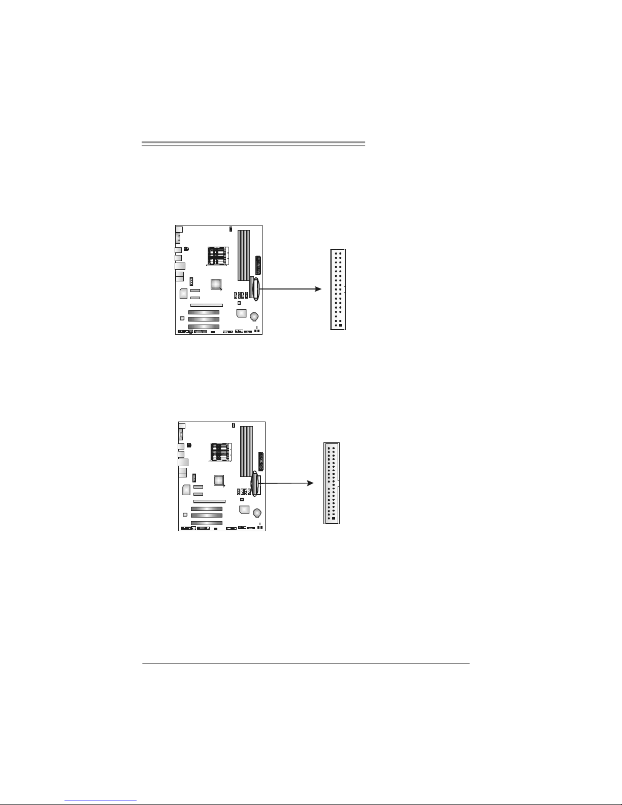
FDD1: Floppy Disk Connector
The motherboard provides a standard floppy disk connector that supports 360K,
720K, 1.2M, 1.44M and 2.88M floppy disk types. This connector supports the
provided floppy drive ribbon cables.
34 33
12
IDE1: Hard Disk Connectors
The motherboard has a 32-bit Enhanced PCI IDE Controller that provides PIO
Mode 0~4, Bus Master, and Ultra DMA 33/66/100/133 functionality.
The IDE connector can connect a master and a slave drive, so you can connect
up to two hard disk drives.
21
3940
Page 14
Motherboard Manual
12
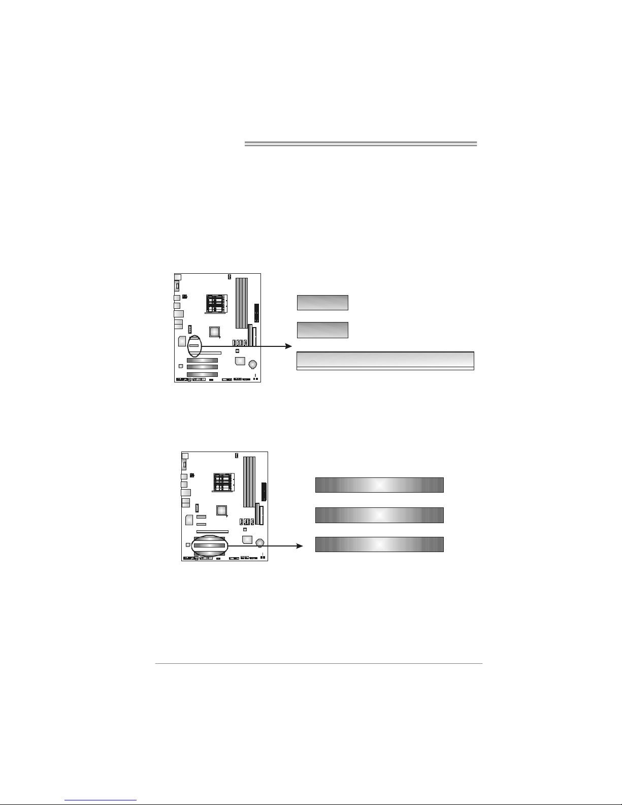
PEX16-1: PCI-Express x16 Slot
- PCI-Express 1.0a compliant.
- Maximum theoretical realized bandwidth of 4GB/s simultaneously per
direction, for an aggregate of 8GB/s totally.
PEX1_1/PEX1_2: PCI-Express x1 Slots
- PCI-Express 1.0a compliant.
- Data transfer bandwidth up to 250MB/s per direction; 500MB/s in total.
- PCI-Express supports a raw bit-rate of 2.5Gb/s on the data pins.
- 2X bandwidth over the traditional PCI architecture.
PEX1_1
PEX16_1
PEX1_2
PCI1~PCI3: Peripheral Component Interconnect Slots
This motherboard is equipped with 3 standard PCI slots. PCI stands for
Peripheral Component Interconnect, and it is a bus standard for expansion
cards. This PCI slot is designated as 32 bits.
PCI 1
PCI2
PCI3
Page 15
TF520 A2+/TF560 A2+
13
CHAPTER 3: HEADERS & JUMPERS SETUP
3.1 H
OW TO SETUP JUMPERS
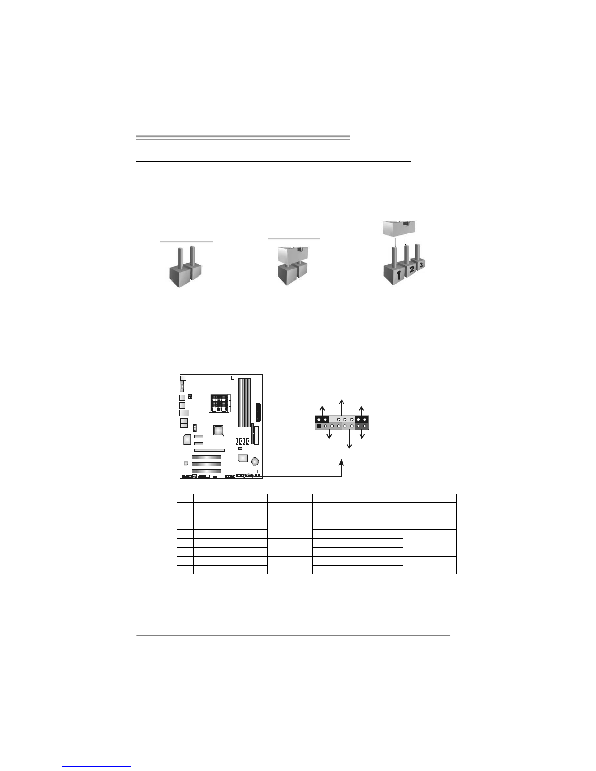
The illustration shows how to set up jumpers. When the jumper cap is
placed on pins, the jumper is “close”, if not, that means the jumper is
“open”.
Pin opened Pin closed Pin1-2 closed
3.2 DETAIL SETTINGS
JPANEL1: Front Panel Header
This 16-pin connector includes Power-on, Reset, HDD LED, Power LED, Sleep
button and speaker connection. It allows user to connect the PC case’s front
panel switch functions.
1
8
16
SLP
PWR_LED
On/Off
RST
HLED
SPK
++
+
9
-
-
Pin Assignment Function Pin Assignment Function
1 +5V 9 Sleep control
2 N/A 10 Ground
Sleep button
3 N/ A 1 1 N/ A N/A
4 Speaker
Speaker
Connector
12 Power LED (+)
5 HDD LED (+) 13 Power LED (+)
6 HDD LED (-)
Hard drive
LED
14 Power LED (-)
Power LED
7 Ground 15 Power button
8 Reset control
Reset button
16 Ground
Power-on button
Page 16
Motherboard Manual
14
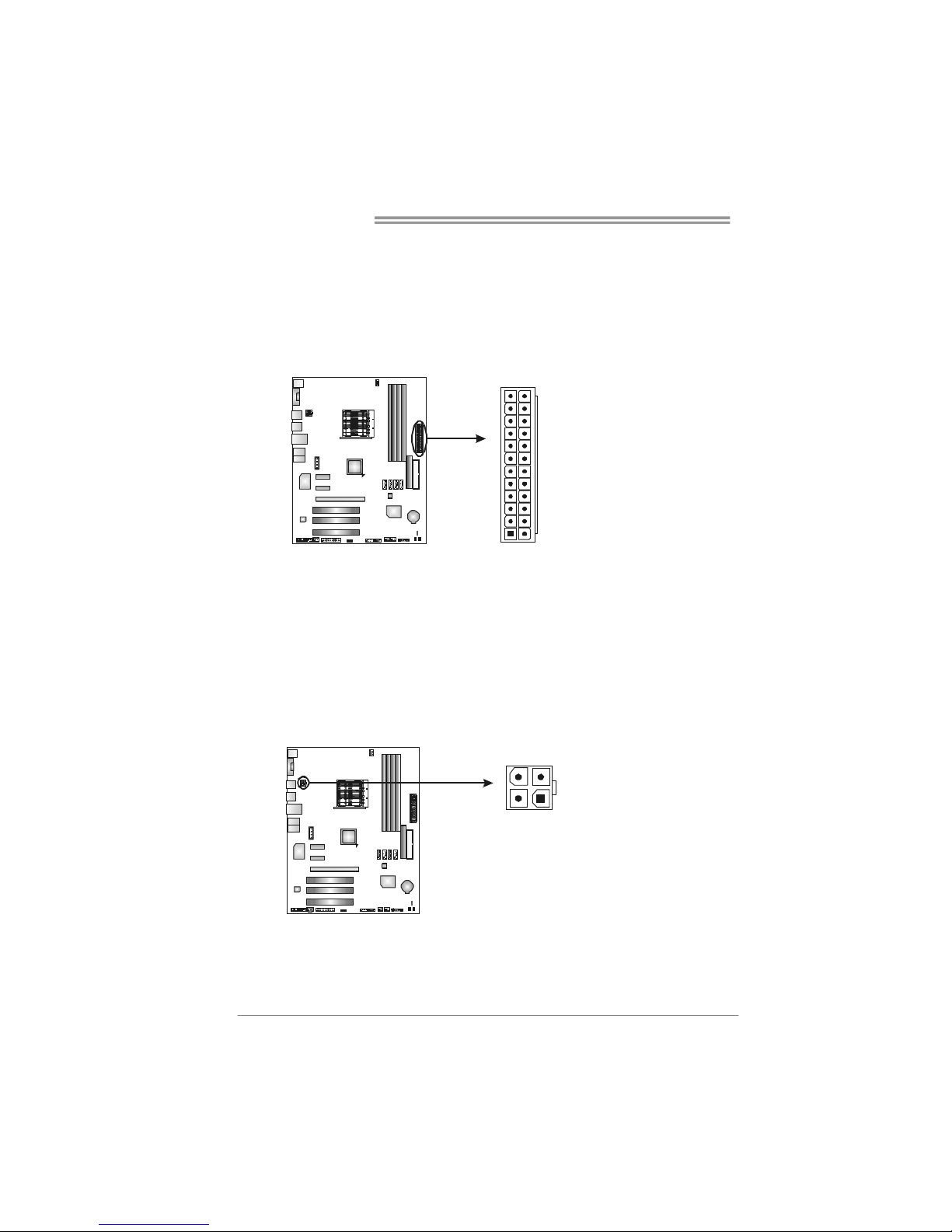
JATXPW R1: AT X Power Source Conne ctor
This connector allows user to connect 24-pin power connector on the AT X
power supply.
Pin Assignment
1 +3.3V
2 +3.3V
3 Ground
4 +5V
5 Ground
6 +5V
7 Ground
8 PW_OK
9 Standby Voltage +5V
10 +12V
11 +12V
12 +3.3V
13 +3.3V
14 -12V
15 Ground
16 PS-ON
17 Ground
18 Ground
19 Ground
20 NC
21 +5V
22 +5V
23 +5V
1
13
12
24
24 Ground
JATXPW R2: AT X Power Source Conne ctor
By connecting this connector, it will provide +12V to CPU power circuit.
Pin
Assignment
1 +12V
2 +12V
3 Ground
4 Ground
1
23
4
Page 17
TF520 A2+/TF560 A2+
15
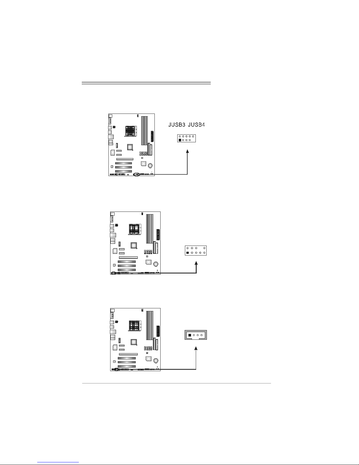
JUSB3/JUSB4: Headers for USB 2.0 Ports at Front Panel
This header allows user to connect additional USB cable on the PC front panel,
and also can be connected with internal USB devices, like USB card reader.
Pin
Assignment
1 +5V (fused)
2 +5V (fused)
3 USB4 USB5 USB+
6 USB+
7 Ground
8 Ground
9 Key
1
2910
JAUDIOF1: Front Panel Audio Header
This header allows user to connect the front audio output cable with the PC front
panel. It will disable the output on back panel audio connectors.
Pin Assignment
1 Mic Left in
2 Ground
3 Mic Right in
4 GPIO
5 Right line in
6 Jack Sense
7 Front Sense
8 Key
9 Left line in
10 Jack Sense
1
9
2
10
JCDIN1: CD-ROM Audio-in Connector
This connector allows user to connect the audio source from the variaty devices,
like CD-ROM, DVD-ROM, PCI sound card, PCI TV turner card etc.
Pin
Assignment
1 Left Channel
Input
2 Ground
3 Ground
1
4
4 Right Channel
Input
Page 18
Motherboard Manual
16
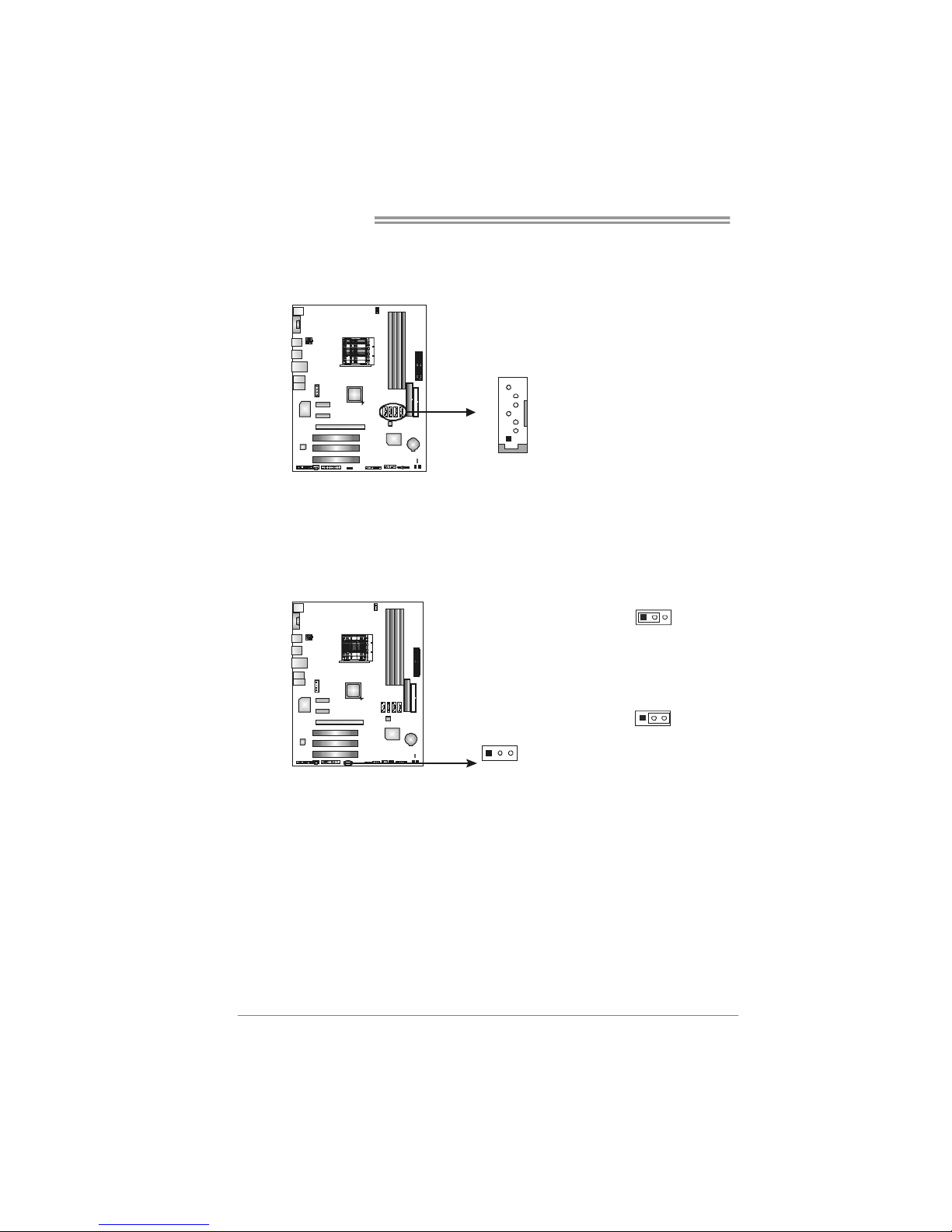
SATA1~SATA4: Serial AT A Connectors
The motherboard has a PCI to SATA Controller with 4 channels SATA interface,
it satisfies the SATA 2.0 spec and with transfer rate of 3.0Gb/s.
Pin
Assignment
1 Ground
2 TX+
3 TX4 Ground
5 RX6 RX+
1
4
7
SATA1
SATA3
SATA2 SATA4
7 Ground
JCMOS1: Clear CMOS Header
By placing the jumper on pin2-3, it allows user to restore the BIOS safe setting
and the CMOS data, please carefully follow the procedures to avoid damaging
the motherboard.
1
3
Pin 1-2 Close:
Normal Operation
(default).
13
1
3
Pin 2-3 Close:
Clear CMOS data.
※ Clear CMOS Procedures:
1. Remove AC power line.
2. Set the jumper to “Pin 2-3 close”.
3. Wait for five seconds.
4. Set the jumper to “Pin 1-2 close”.
5. Power on the AC.
6. Reset your desired password or clear the CMOS data.
Page 19
TF520 A2+/TF560 A2+
17
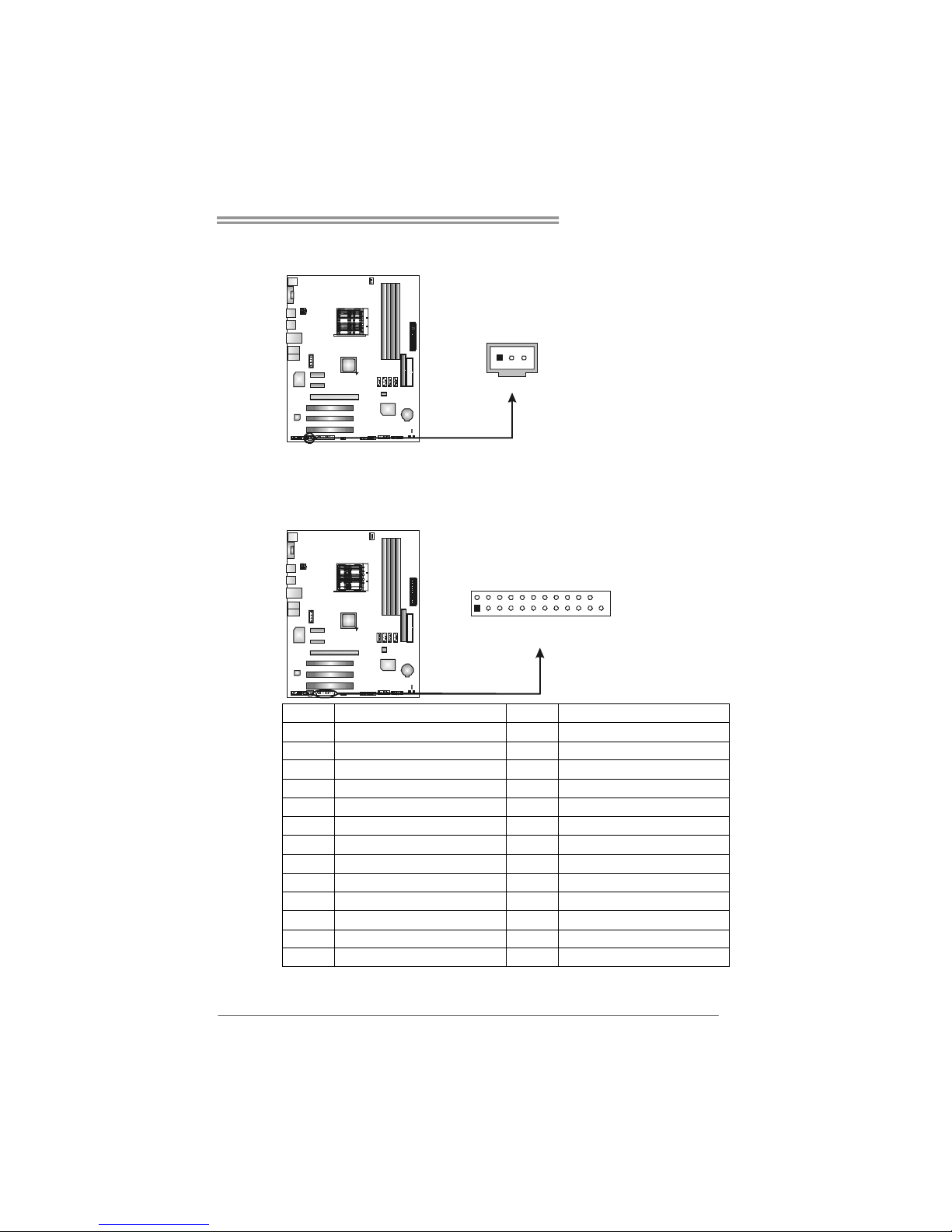
JSPDIF_OUT1: Digital Audio out Connector
This connector allows user to connect the PCI bracket SPDIF output header.
Pin
Assignment
1 +5V
2 SPDIF_OUT
1
3
3 Ground
JPRNT1: Printer Port Connector
This header allows you to connector printer on the PC.
2
1
25
Pin Assignment Pin Assignment
1 -Strobe 14 Ground
2 -ALF 15 Data 6
3 Data 0 16 Ground
4 -Error 17 Data 7
5 Data 1 18 Ground
6 -Init 19 -ACK
7 Data 2 20 Ground
8 -Scltin 21 Busy
9 Data 3 22 Ground
10 Ground 23 PE
11 Data 4 24 Ground
12 Ground 25 SCLT
13 Data 5 26 Key
Page 20
Motherboard Manual
18
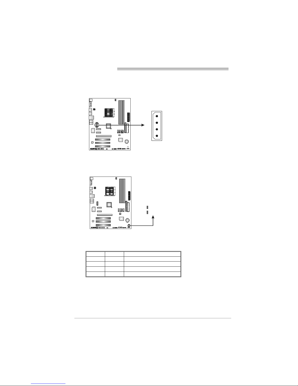
JATXPWR3: Auxiliary Power for Graphics
This connector is an auxiliary power connection for graphics cards. Exclusive
power for the graphics card provides better graphics performance.
Pin
Assignment
1 +12V
2 Ground
3 Ground
4 VCC
1
4
On-Board LED Indicators
There are 2 LED indicators on the motherboard to show system status.
LED_D1
LED_D2
LED_D1 and LED_D2:
These 2 LED indicate system power on diagnostics.
Please refer to the table below for different messages:
LED_D1 LED_D2 Message
ON ON Norma l
ON OFF Memory Error
OFF ON VGA Error
OFF OFF Abnormal: CPU / Chipset error.
Page 21

TF520 A2+/TF560 A2+
19
On-Board Buttons
There are 2 on-board buttons.
PWRSW1RSTSW1
PWRSW1:
This is an on-board Power Switch button.
RSTSW1:
This is an on-board Reset button.
Page 22
Motherboard Manual
20
CHAPTER 4: NVIDIA RAID FUNCTIONS
4.1 O
PERATION SYSTEM
z Supports Windows XP Home/Professional Edition, and Windows 2000 Professional.
4.2 RAID ARRAYS
NVRAID supports the following types of RAID arrays:
RAID 0: RAID 0 defines a disk striping scheme that improves disk read and write times for
many applicat ions.
RAID 1: RAID 1 defines techniques for mirroring data.
RAID 0+1: RAID 0+1 combines the techniques used in R AID 0 and RAID 1.
RAID 5: RAID 5 provides fault tolerance and better utilization of disk capacity.
4.3 HOW RAID WORKS
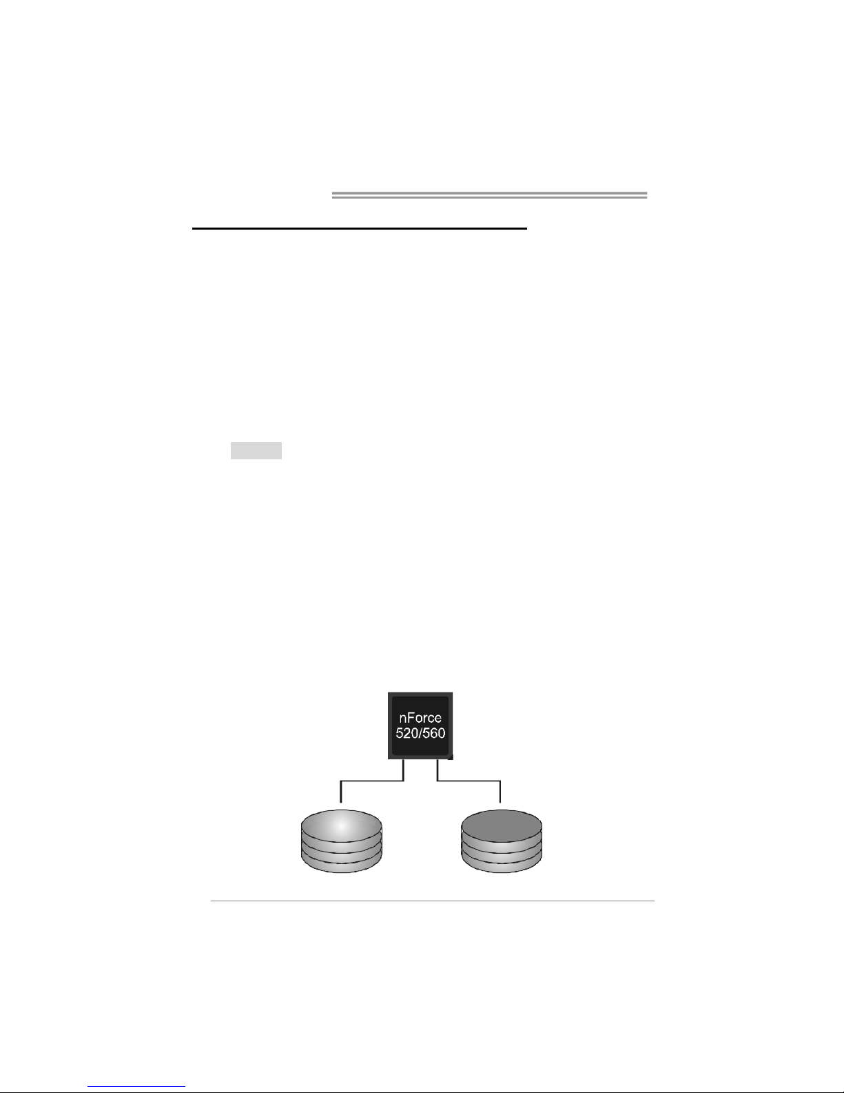
RAID 0:
The controller “stripes” data across multiple drives in a RAID 0 array system. It breaks
up a large f i le into sma ller bloc ks an d pe rfo rms d isk r ead s and writes acr oss multip le
drives in parallel. The size of each block is determined by the stripe size parameter,
which you set durin g the creation of the RAID set based on the system environment. This
technique reduces overall disk access time and offers high bandwidth.
Features and Benefits
Drives: Minimum 1, and maximum is up to 6 or 8. Depending on the
platform.
Uses: Intended for non-critical data requiring high data throughput, or any
environment that does not require fault tolerance.
Benefits: provides increased data throughput, especially for large files. No
capacity loss penalty for parity.
Drawbacks: Does not deliver any fault tolerance. If any drive in the array
fails, all data is lost.
Fault Tolerance: No.
Blo ck 1
Block 3
Block 5
Block 2
Block 4
Block 6
Page 23
TF520 A2+/TF560 A2+
21
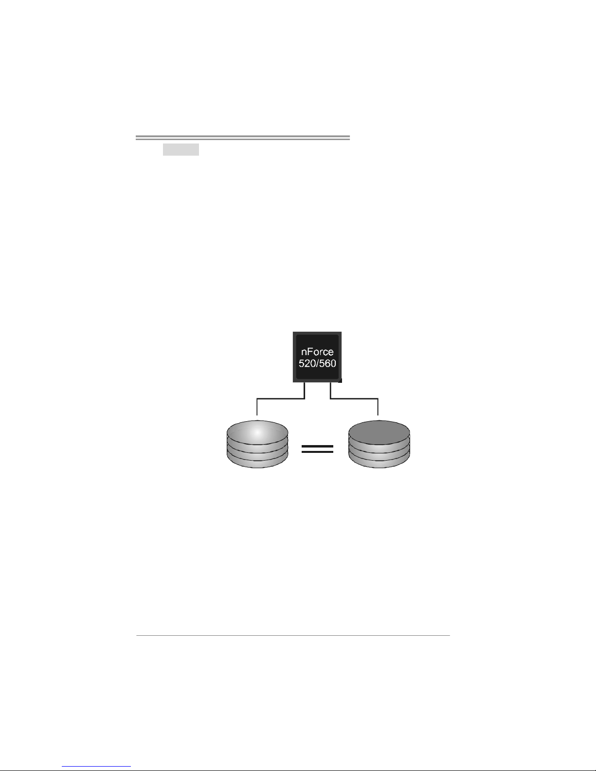
RAID 1:
Every read and write is actua lly carried out in parallel across 2 disk drives in a RAID 1
array system. The mirrored (backup) copy of the data can reside on the same disk or on a
second redundant drive in the array. RAID 1 provides a hot-standby copy of data if the
active volume or drive is corrupted or becomes unavailable because of a hardware failure.
RAID techniques can be applied for high-availability solut ions, or as a form of automatic
backup that eliminates tedious manual backups to more expensive and less reliab le
media.
Features and Benefits
Drives: Minimum 2, and maximum is 2.
Uses: RAID 1 is ideal for small databases or any other application that
requires fault tolerance and minimal capacity.
Benefits: Provides 100% data redundancy. Should one drive fail, the
controller switches to the other drive.
Drawbacks: Requires 2 drives for the storage space of one drive.
Performance is impaired during drive rebuilds.
Fault Tolerance: Yes.
Block 1
Block 2
Block 3
Block 1
Block 2
Block 3
Page 24
Motherboard Manual
22
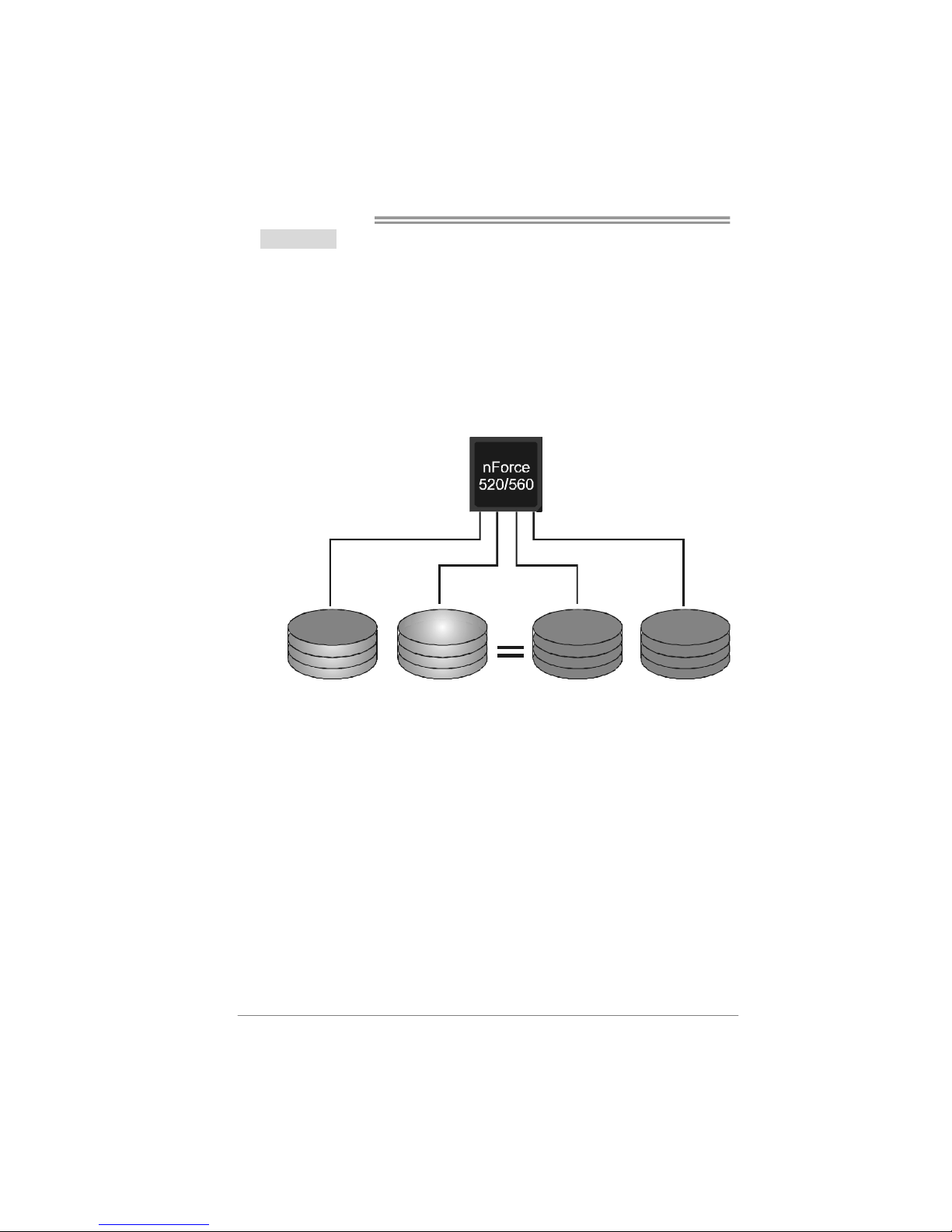
RAID 0+1:
RAID 0 drives can be mirrored us ing RAID 1 techniques. Resulting in a RAID 0+1
solution for improved performance plus resiliency.
Features and Benefits
Drives: Minimum 4, and maximum is 6 or 8, depending on the platform.
Benefits: Optimizes for both fault tolerance and performance, allowing for
automatic redundancy. May be si multaneously used with other RAID levels
in an array, and allows for spare disks.
Drawbacks: Requires twice the available disk space for data redundancy,
the same as RAID level 1.
Fault Tolerance: Yes.
Block 2
Block 4
Block 6
Bloc k 1
Block 3
Block 5
Block 2
Block 4
Block 6
Block 1
Block 3
Block 5
Page 25
TF520 A2+/TF560 A2+
23
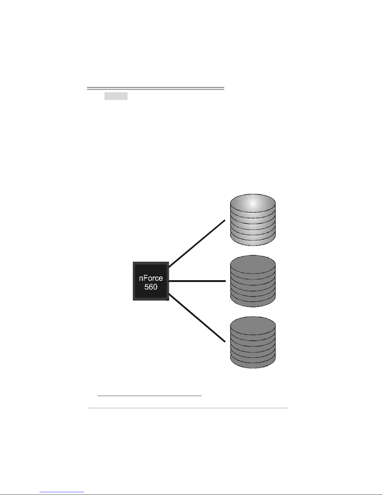
RAID 5:
RAID 5 stripes both data and parity information across three or more drives. It writes
data and parity blocks across all the drives in the array. Fault tolerance is maintained by
ensuring that the parity information for any given block of data is placed on a different
drive from those used to store the data itself.
Features and Benefits
Drives: Mini mu m 3.
Uses: RAID 5 is recommended for transaction processing and general
purpose service.
Benefits: An ideal combination of good performance, good fault tolerance,
and high capacity and storage efficiency.
Drawbacks: Individual block data transfer rate same as a single disk. Write
performance can be CPU intensive.
Fault Tolerance: Yes.
Disk 1
DATA 3
PARIT Y
DATA 7
DATA 1
DATA 9
PARIT Y
Disk 2
PARIT Y
DATA 5
DATA 8
DATA 2
PARIT Y
DATA 11
Disk 3
DATA 4
DATA 6
PARIT Y
PARIT Y
DATA 10
DATA 12
※ For more detailed setup information, ple ase refer to the Driver CD, or go to
http://www.nvidia.com/page/pg_20011106217193.html to download NVIDIA nForce Tutorial Flash.
Page 26
Motherboard Manual
24
CHAPTER 5: OVERCLOCK QUICK GUIDE
5.1 T-P
OWER INTRODUCTION
Biostar T-Power is a whole new utility that is desig ned for overclock users.
Based on many precise tests, Biostar Engineering Team (BET) has
developed this ultimate overclock engine to raise system performance.
No matter whether under BIOS or Windows interface, T-Power is able to
present the best system state according to users’ overclock setting.
T-Power BIOS Features:
Overclocking Navigator Engine (O.N.E.)
CMOS Reloading Program (C.R.P.)
Memory Integration Test (M.I.T., under Overclock Navigator Engine)
Integrated Flash Program (I.F.P.)
Self Recovery System (S.R.S)
Smart Fan Function (under PC Health Status)
T-Power Windows Feature:
Hardware Monitor
Overclock Engine
System Infor mation
!! WARNING !!
For better system performance, the BIOS firmware is being
continuously updated. The BIOS information described below in
this manual is for your reference only and the actual BIOS
information and settings on board may be different from this
manual. For further information of setting up the BIOS, please
refer to the BIOS Manual in the Setup CD.
Page 27
TF520 A2+/TF560 A2+
25
5.2 T-POWER BIOS FEATURE
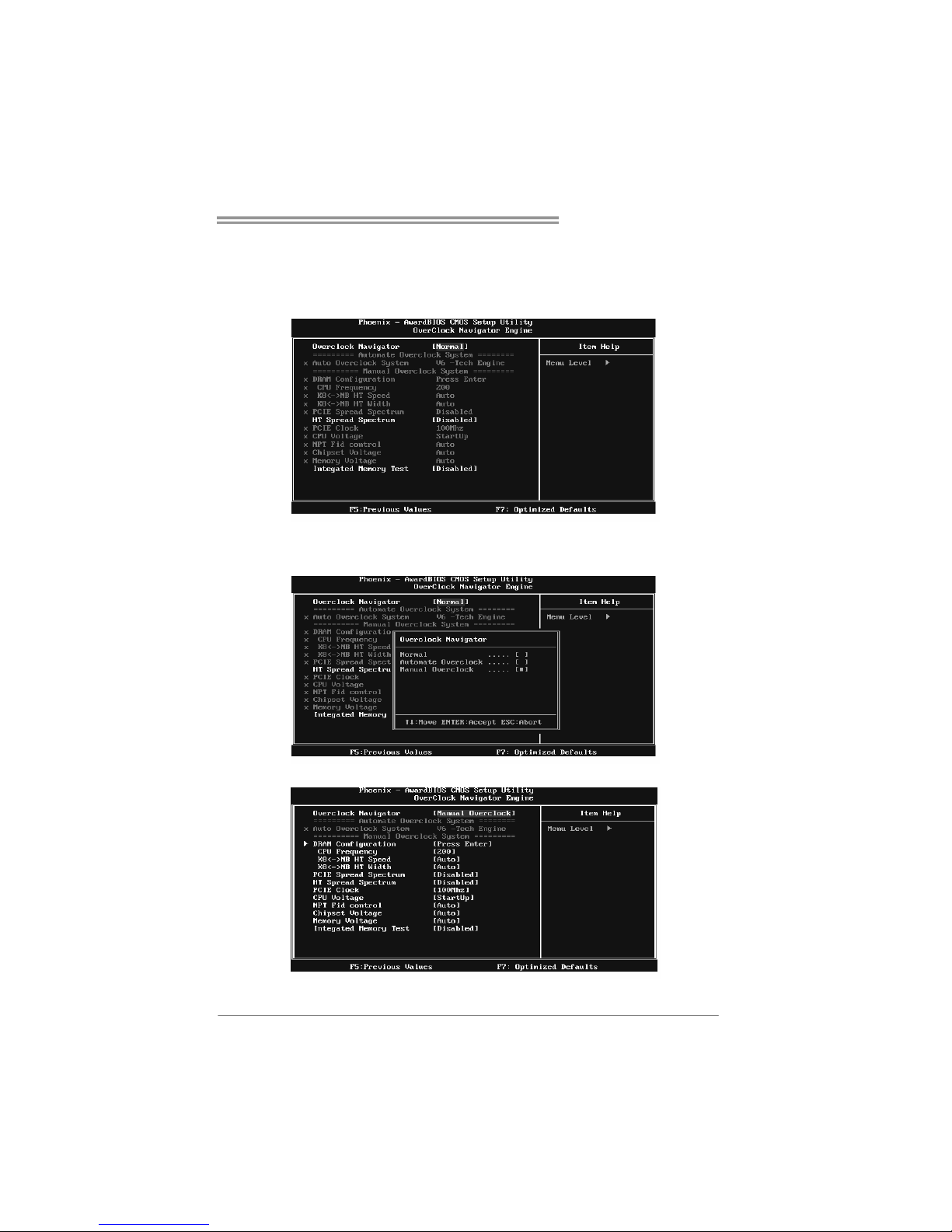
A. Overclocking Navigator Engine (O.N.E.):
ONE provides two powerful overclocking engines: MOS and AOS for both
Elite and Casual overclockers.
Manual Overclock System (M.O.S.)
MOS is designed for experienced overclock users.
It allows users to customize personal overclock settings.
Page 28

Motherboard Manual
26
DRAM Configuration:
Enter this function for more advanced DRAM settings.
CPU Frequency:
CPU Frequency is directly in proportion to system performance. To
maintain the system stability, CPU voltage needs to be increased also
when raising CPU frequency.
K8<->NB HT Spee d:
This option controls the HyperTransport speed of CPU to northbridge
chipset.
K8<->NB HT Width:
This option controls the HyperTransport width of CPU to northbridge
chipset.
PCIE Spread Spectrum:
This BIOS feature allows you to reduce the EMI of the PCI Express bus by
modulating the signals it generates so that the spikes are reduced to flatter
curves. Please disable this option when proceeding overclocking.
HT Spre ad Spectrum:
Please disable this option when proceeding overclocking.
PCIE Clock:
It helps to increase VGA card perfor mance.
CPU Voltage:
This function will increase CPU stability when overclocking. However, the
CPU temperature will increase when CPU voltage is increased.
NPT Fid Contro l:
This function allows you to adjust the frequency ratio of CPU.
Chipset Voltage:
This function will increase chipset stability when overclocking.
Memory Voltag e :
This function will increase memory stability when overclocking.
Page 29
TF520 A2+/TF560 A2+
27
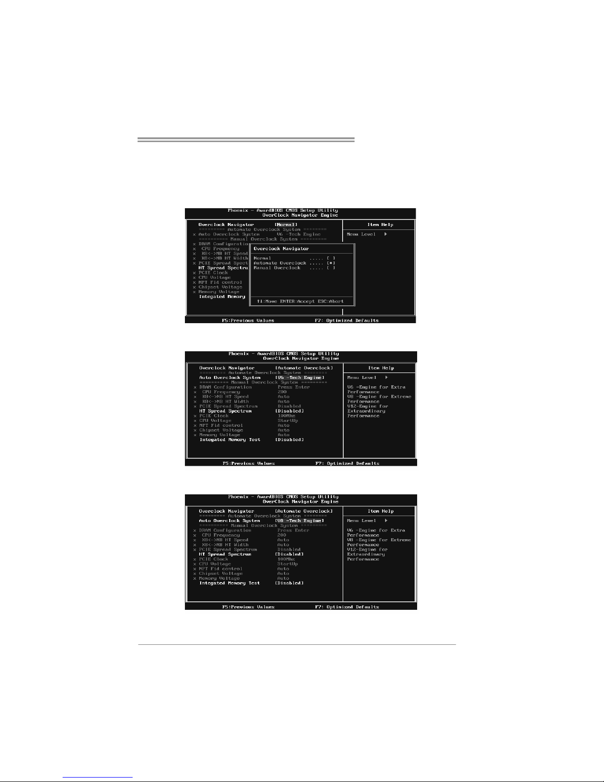
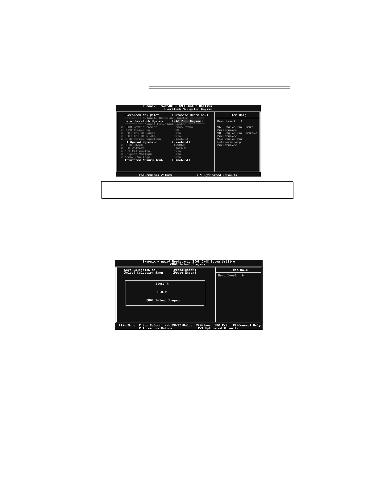
Automatic Overclock System (A.O.S.)
For beginners in overclock field, BET had developed an easy, fast, and
powerful feature to increase the system performance, named A.O.S.
Based on many tests and experiments, A.O.S. provides 3 ideal overclock
configurations that are able to raise the system performance in a single
step.
V6 Tech Engine:
This setting will raise about 10%~15% of whole system performance.
V8 Tech Engine:
This setting will raise about 15%~25% of whole system performance.
Page 30
Motherboard Manual
28
V12 Tech Engine:
This setting will raise about 25%~30% of whole system performance.
Notice s:
1. Not all types of AMD CPU perform above overclock setting ideally; the difference will be based
on the selected CPU model.
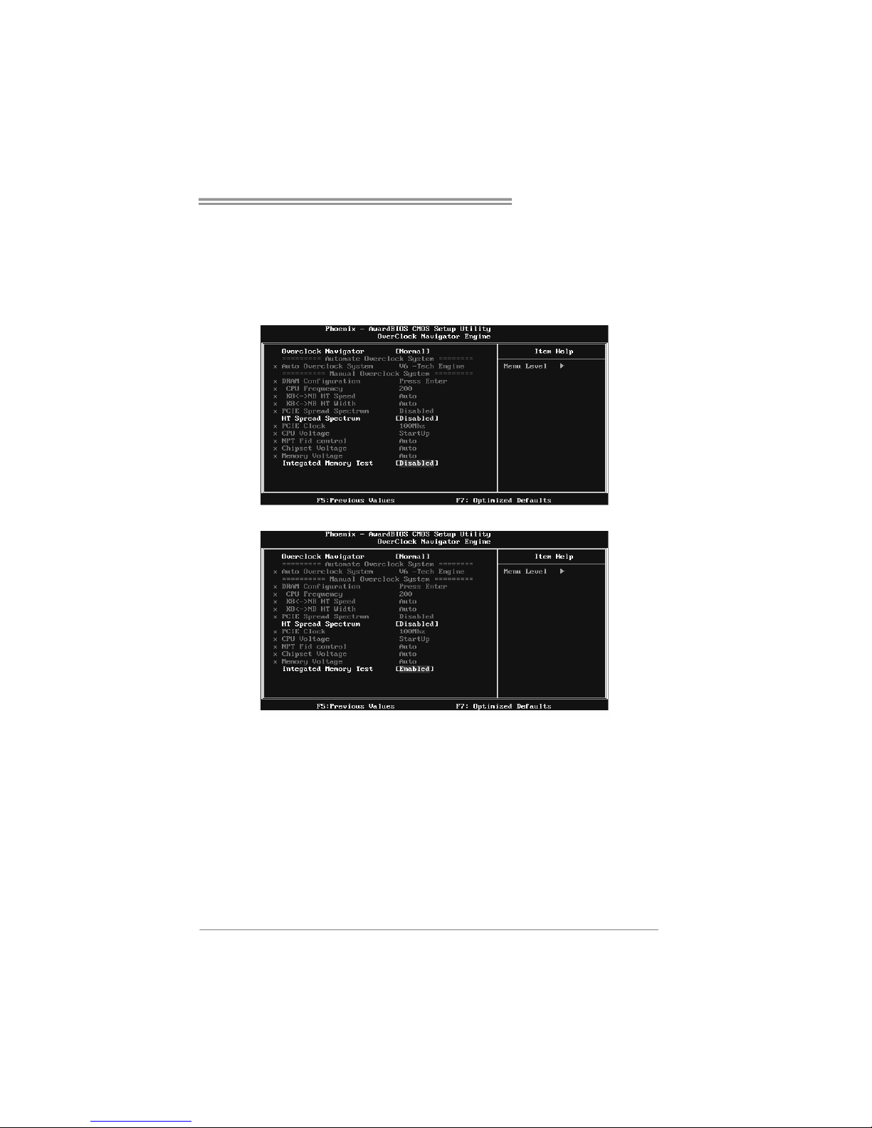
B. CMOS Reloading Program (C.R.P.):
It allows users to save different CMOS settings into BIOS-ROM.
Users are able to reload any saved CMOS setting for customizing system
configurations.
Moreover, users are able to save an ideal overclock setting during overclock
operation.
There are 50 sets of record addresses in total, and users are able to name the
CMOS data according to personal preference.
Page 31
TF520 A2+/TF560 A2+
29
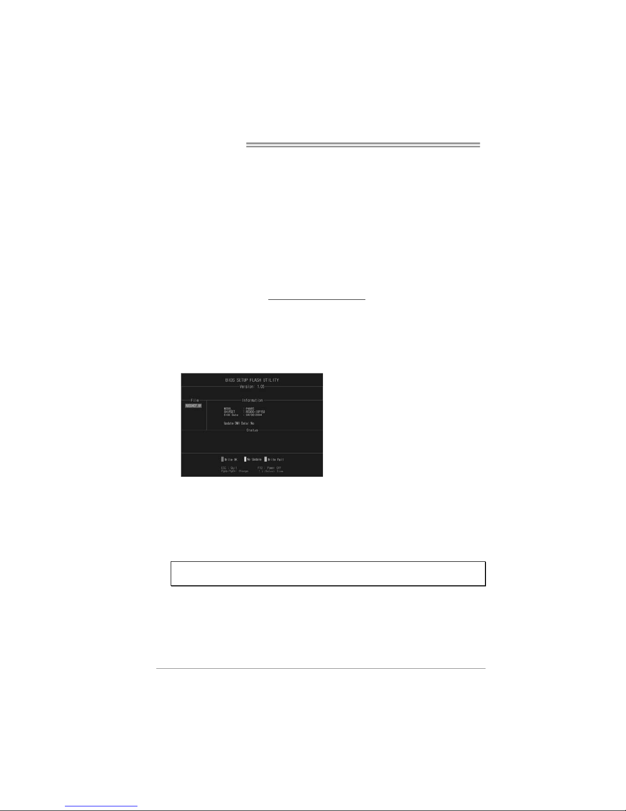
C. Memory Integration Test (M.I.T.):
This function is under “Overclocking Navigator Engine” item.
MIT allows users to test memory compatibilities, and no extra devices or
software are needed.
Step 1:
The default setting under this item is “Disabled”; the condition parameter should
be changed to “Enable” to proceed this test.
↓
Step 2:
Save and Exit from CMOS setup and reboot the system to activate this test.
Run this test for 5 minutes (minimum) to ensure the memory stability.
Step 3:
When the process is done, change the setting back from “Enable” to “Disable”
to complete the test.
Page 32
Motherboard Manual
30
D. Self Recovery System (S.R.S.):
This function can’t be seen under T-Power BIOS setup; and is always on
whenever the system starts up.
However, it can prevent system hang-up due to inappropriate overclock
actions.
When the system hangs up, S.R.S. will automatically log in the default BIOS
setting, and all overclock settings will be re-configured.
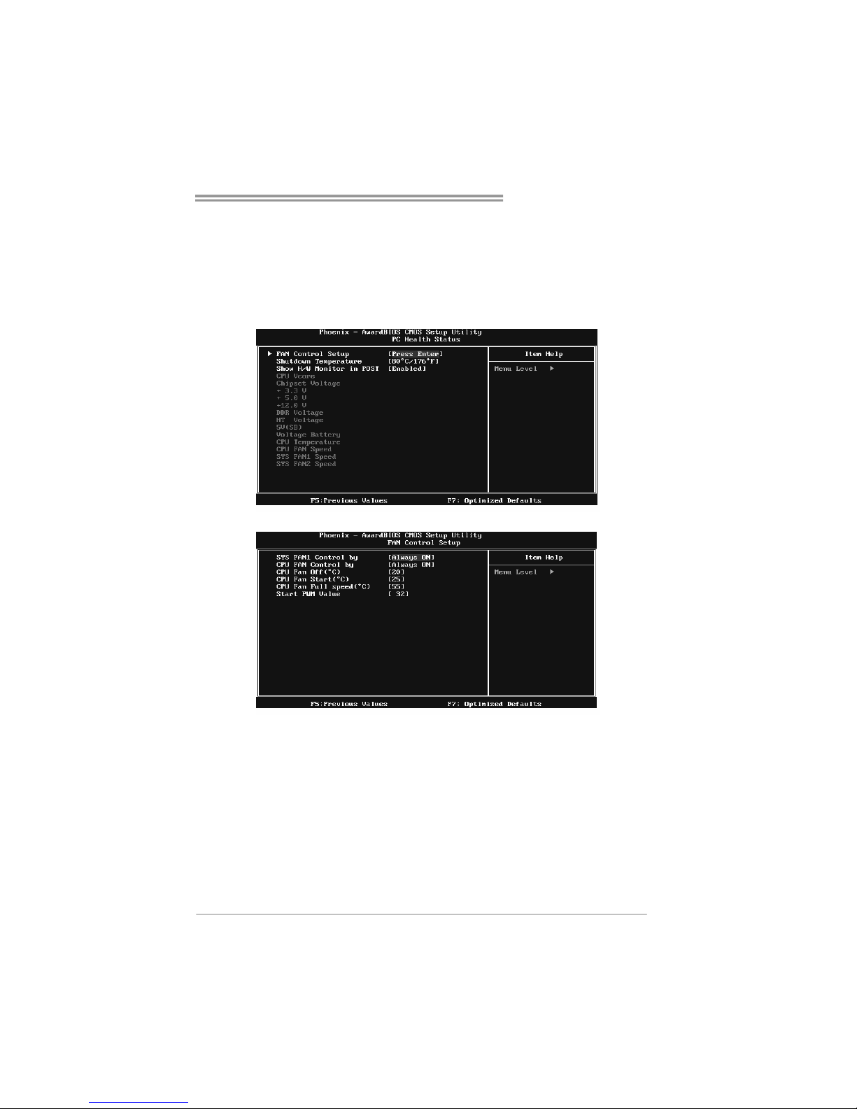
E. Integrated Flash Program (I.F.P.):
IFP is a safe and quick way to upgrade BIOS.
Step 1:
Go to Biostar website (http://www.biostar.com.tw
) to download the latest BIOS
file. Then, save the file into a floppy disk.
Step 2:
Insert the floppy disk and reboot the system to get into CMOS screen.
Step 3:
Select the item “Integrated Flash Program” to get the following frame and
choose the BIOS file downloaded in step 1.
Step 4:
Press “Enter” key to start BIOS file loading, and BIOS updating will process
automatically.
Step 5:
When the BIOS update is completed, press YES to the message “Flash done,
Reset system”, and the system will reboot automatically to finish the process.
Advise:
You can update the system BIOS by simply pressing “Enter” key for three times.
Page 33
TF520 A2+/TF560 A2+
31
F. Smart Fan Function:
Smart Fan Function is under “PC Health Status”.
This is a brilliant feature to control CPU Temperature vs. Fan speed.
When enabling Smart Fan function, Fan speed is controlled automatically by
CPU temperature.
This function will protect CPU from overheat problem and maintain the system
temperature at a safe level.
↓
SYS FAN1 Control by:
This option controls the northbridge fan. Select “ Smart” to activate smart
fan function for reducing the noise and power consuming of the fan.
CPU FAN Control by:
This option controls the CPU fan. Select “ Smart” to activate smart fan
function for reducing the noise and power consuming of the fan.
CPU Fan Off <℃>:
If the CPU temperature is lower than the set value, the CPU fan will turn
off. The range is from 0℃~127℃, with an interval of 1℃.
Page 34

Motherboard Manual
32
CPU Fan Start <℃>
The CPU fan starts to work when CPU temperature arrives to this set
value. The range is from 0℃~127℃, with an interval of 1℃.
CPU Fan Full speed <℃ >
When CPU temperature arrives to the set value, the CPU fan will work
under Full Speed. The range is from 0℃~127℃, with an interval of 1℃.
Start PWM Value
When CPU temperature arrives to the set value, the CPU fan will work
under Smart Fan Function mode. The range is from 0~127, with an
interval of 1.
Page 35
TF520 A2+/TF560 A2+
33
5.3 T-POWER WINDOWS FEATURE
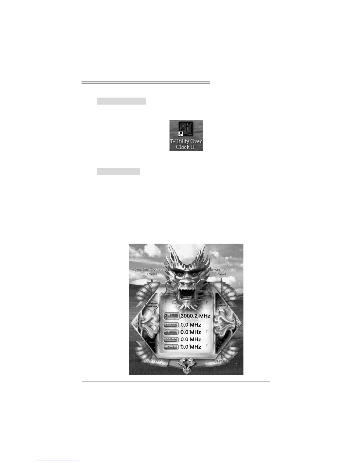
1. Desktop Icon
After the T-Utility has bee n installed, a T-Utility ico n will appear on the
desktop, just like the icon shown below.
Now you can launch the T-Utility simply by double-clicking the desktop
icon.
2. Main Panel
If you double-click the desktop icon, T-Utility will be launched. Please
refer to the following fig ure; the utility’s first window you will see is
Main Panel.
Main Panel contains features as follows:
a. Display the CPU Speed, CPU external clock, Memory clock, VGA
clock, and PCI clock information.
b. Contains About, Overclock/Overvoltage, and Hardware Monitor
Buttons for invoking respective panels. The On/Off button is for
closing the program.
Page 36
Motherboard Manual
34
3. Overclock/Overvoltage Panel
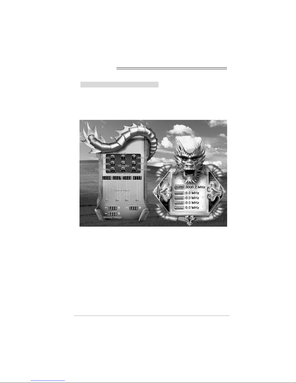
Click the Overclock/Overvoltage button in the Main Panel, the button
will be highlighted and the Overclock/Overvoltage Panel will show
up as the following figure. As you can see, the Overclock Panel is
on the upper side, and the Overvoltage Panel is on the lower side.
Page 37
TF520 A2+/TF560 A2+
35
Overclock Panel contains these features:
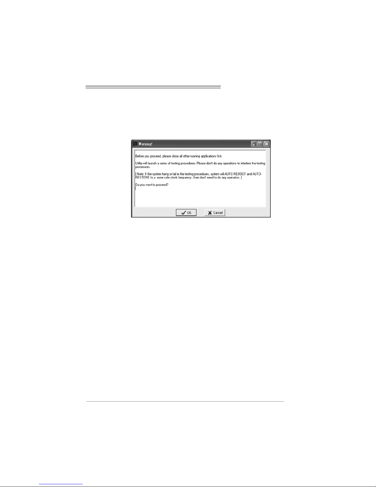
a. “Auto-Overclock”:
User can click this button and T-Utility will set the best and stable
performance and frequency automatically. A warning dialog as
below will show up to notify you that the system may become
unstable, click on “OK” to continue.
Then T-Utility will exec ute a series of testing until system fail.
Then system will do fail-safe reboot by using Watchdog function.
After reboot, launch the T-Utility again and the utility will load the
previously verified best and stable frequency.
b. “Verify”:
If you use the “Manual Adjust” bar to adjust the CPU frequency,
then you can click t his b utton and T-Utility will proceed a testing for
current frequency. If the testing is ok, then the current frequency
will be saved into system registry. If the testing fails, system will do
a fail-safe rebooting. After reboot, the T-Utility will restore to the
hardware default setting.
Warning:
Manually overclock is potentially dangerous, especially when the
overclocking percentage is over 110 %. We strongly recommend you
verify every speed you overclock by click the Verify button. Or, you can
just click Auto overclock button and let T-Utility automatically gets the
best result for you.
c. “V3 Engine”/“V6 Engine”/“V9 Engine”:
Provide user the ability to do real-time overclock adjustment.
d. “Recovery”:
Click t his b utton and the T-Utility will restore all values to the
hardware default setting.
Page 38
Motherboard Manual
36
e. “Save / Open Setting”:
Click Save button to save current setting to a file, and click Open
button to load a previously saved setting.
f. “Panel Color”:
Click this button to change the color of the panel.
Overvoltage Panel contains these features:
a. “CPU Voltage”:
This function allows user to adjust CPU voltage. Click on “+” to
increase or “-“ to decrease the CPU voltage.
b. “Memory Voltage”:
This function allows user to adjust Memory voltage. Click on “+”
to increase or “-“ to decrease the Memory voltage.
c. “Chipset Voltage”:
This function allows user to adjust Chipset voltage. Click on “+”
to increase or “-“ to decrease the Chipset voltage.
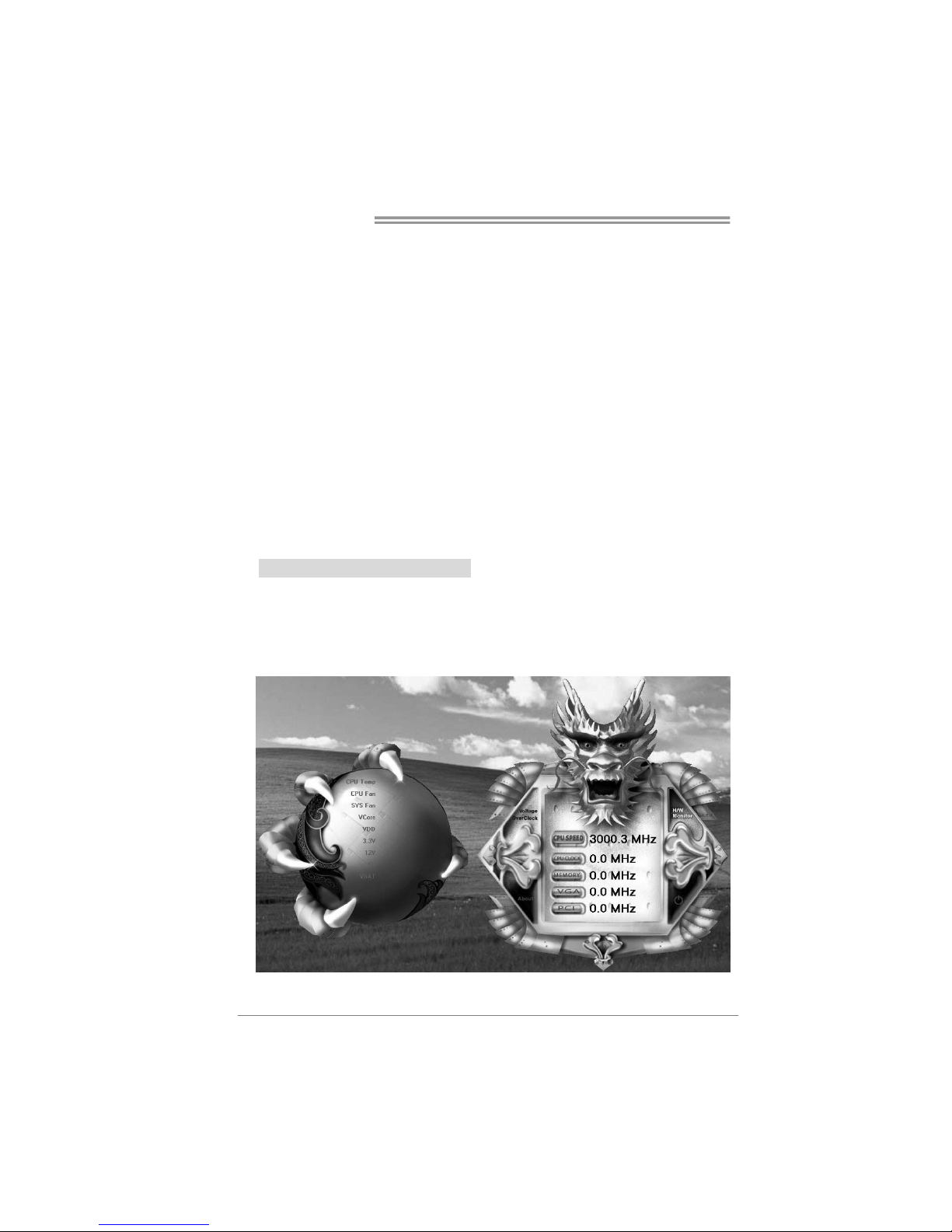
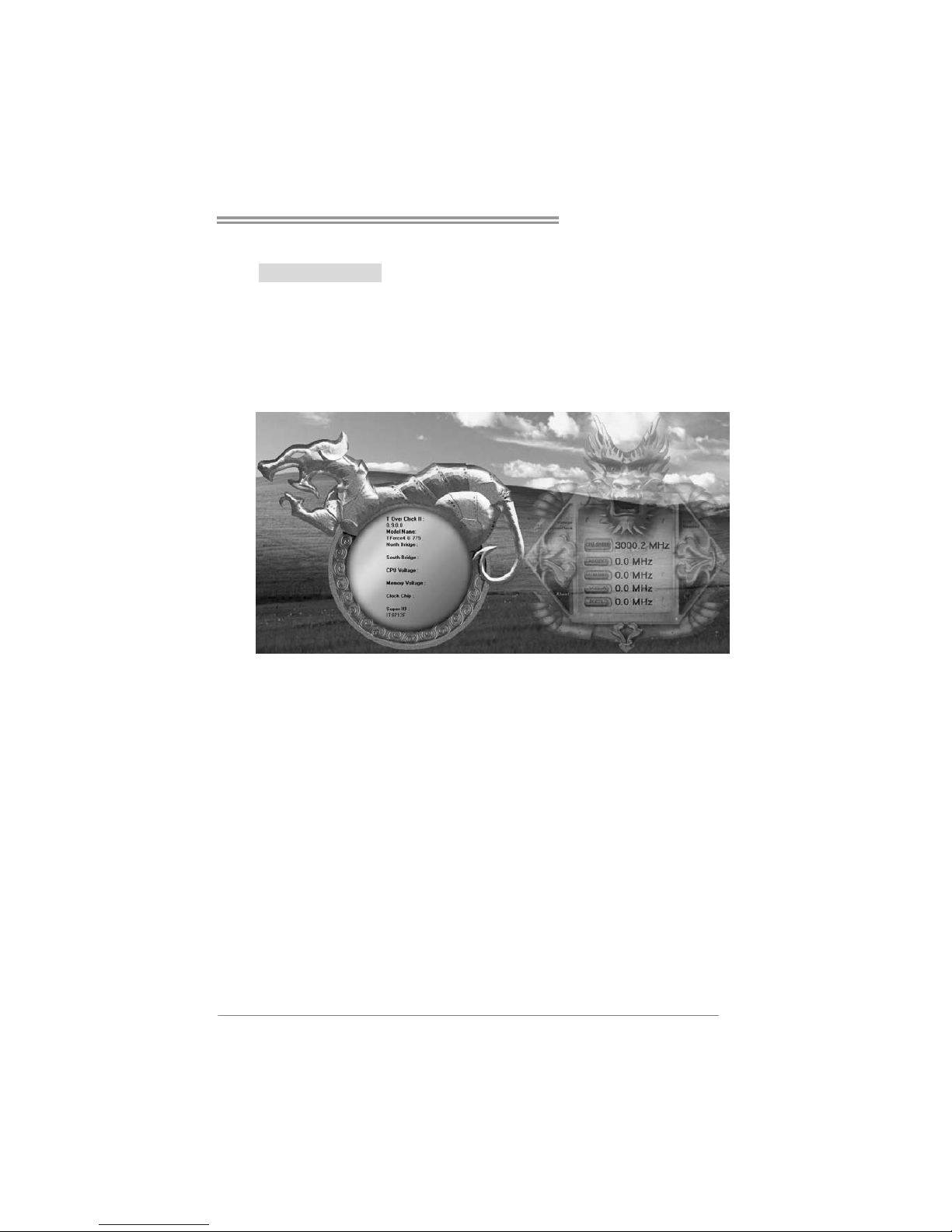
4. Hardware Monitor Panel
Click the Hardware Monitor button in Main Panel, the button will be
highlighted a nd the Hardware Monitor panel will s how up as the
following figure.
In this panel, you can get the real-time status information of your
system. The information will be refreshed e very 1 second.
Page 39
TF520 A2+/TF560 A2+
37
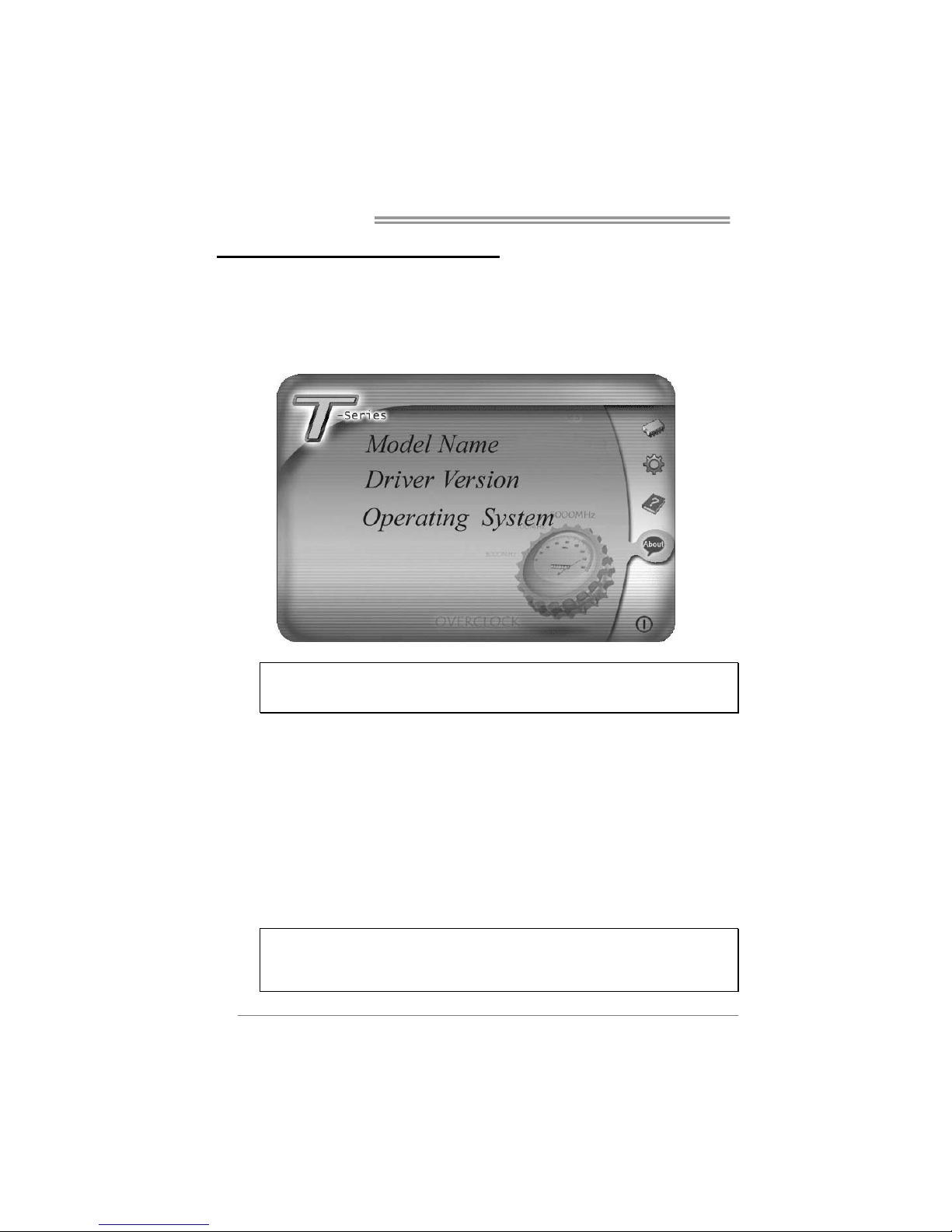
5. About Panel
Click the “about” button in Main Panel, the butto n will be highlighted
and the About Pa nel will show up as the following fig ure.
In this panel, you can get model name and detail information in hints
of all the chipset that are related to overclocking. You can also get
the the version number of T-Utility.
Note:
Because the overclock, overvoltage, and hardware monitor features
are controlled by several separate chipset, T-Utility divides these
features to separate panels. If one chipset is not on board, the
correlative button in Mai n panel will be disabled, but it will not
interfere with other panels’ functions. This property can make
T-Utility more robust.
Page 40
Motherboard Manual
38
CHAPTER 6: USEFUL HELP
6.1 D
RIVER INSTALLATION NOTE
After you installed your operating system, please insert the Fully Setup
Driver CD into your optical drive and install the driver for better system
performance.
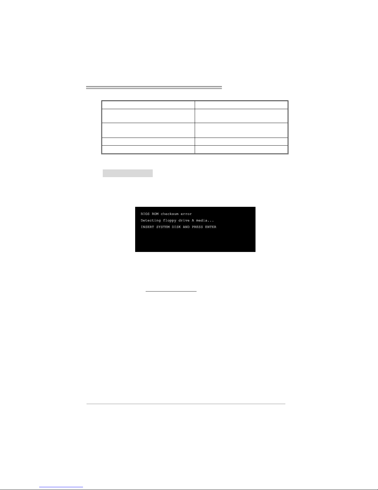
You will see the following window after you insert the CD
The setup guide will auto detect your motherboard and operating system.
Note:
If this window didn’t show up after you insert the Driver CD, please use file browser to
locate and execute the file SETUP.EXE under your optical drive.
A. Driver Installation
To install the driver, please click on the Driver icon. The setup guide will
list the compatible driver for your motherboard and operating system.
Click on each device driver to launch the installation program.
B. Software Installation
To install the software, please click on the Software icon. The setup guide
will list the software available for your system, click on each software title
to launch the installation program.
C. Manual
Aside from the paperback manual, we also provide manual in the Driver
CD. Click on the Manual icon to browse for available manual.
Note:
You will need Acrobat Reader to open the manual file. Please download the latest version
of Acrobat Reader so ftware from
http://www.adobe.com/products/acrobat/readstep2.html
Page 41
TF520 A2+/TF560 A2+
39
6.2 AWARD BIOS BEEP CODE
Beep Sound Meaning
One long beep followed by two short
beeps
Video card not found or video card
memory bad
High-low siren sound CPU overheated
System will shut down automatically
One Short beep when system boot-up No error found during POST
Long beeps every other second No DRAM detected or install
6.3 EXTRA INFORMATION
A. BIOS Update
After you fail to update BIOS or BIOS is invaded by virus, the
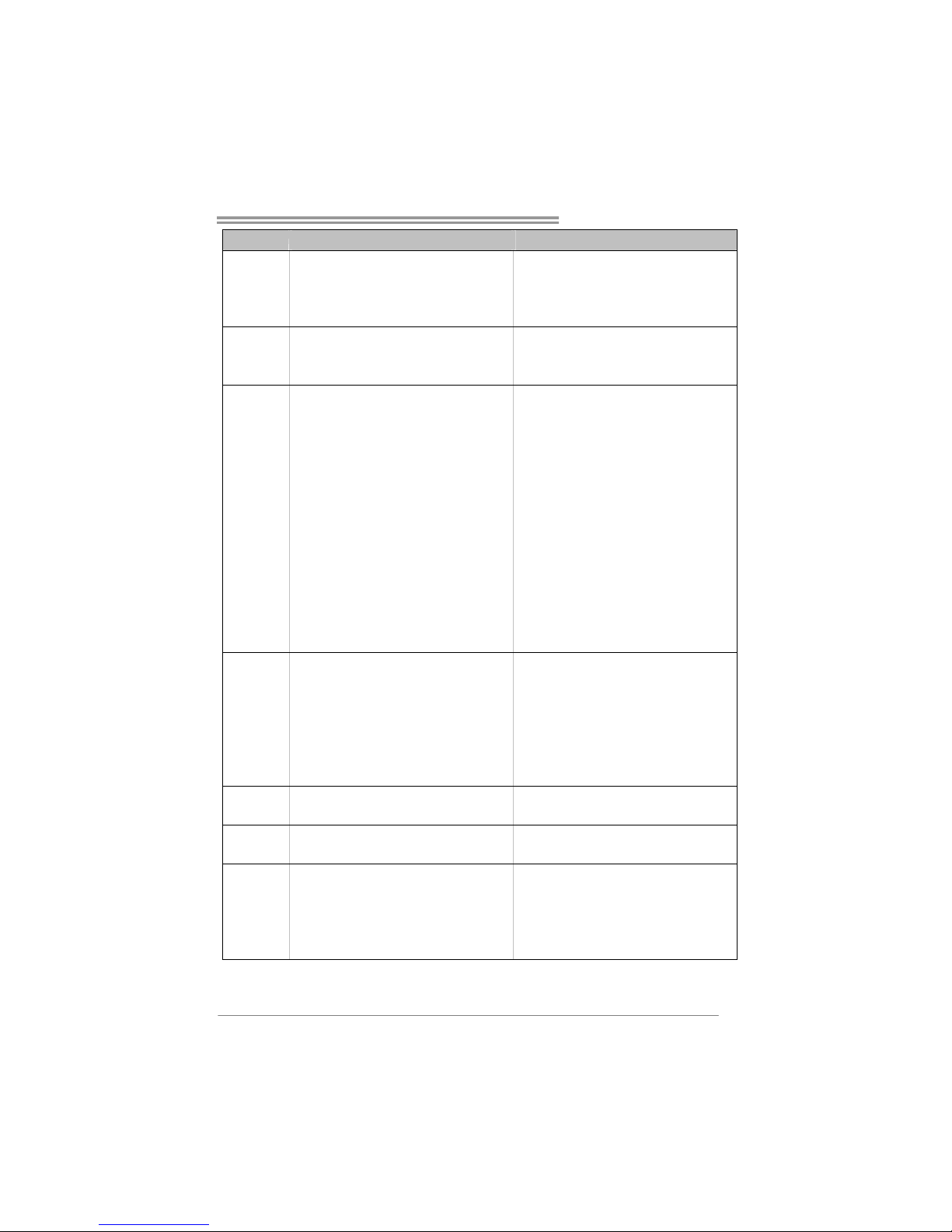
Boot-Block function will help to restore BIOS. If the following message
is shown after boot-up the system, it means the BIOS contents are
corrupted.
In this Case, please follow the procedure below to restore the BIOS:
1. Make a bootable floppy disk.
2. Download the Flash Utility “AWDFLASH.exe” from the Biostar
website: www.biostar.com.tw
3. Confirm motherboard model and download the respectively BIOS
from Biostar website.
4. Copy “AWDFLASH.exe” and respectively BIOS into floppy disk.
5. Insert the bootable disk into floppy drive and press Enter.
6. System will boot-up to DOS prompt.
7. Type “Awdflash xxxx.bf/sn/py/r” in DOS prompt.
(xxxx means BIOS name.)
8. System will update BIOS automatically and restart.
9. The BIOS has been recovered and will work properly.
Page 42

Motherboard Manual
40
B. CPU Overheated
If the system shutdown automatically after power on system for
seconds, that means the CPU protection function has been activated.
When the CPU is over heated, the motherboard will shutdow n
automatically to avoid a damage of the CPU, and the system may not
power on again.
In this case, please double check:
1. The CPU cooler surface is placed evenly with the CPU surface.
2. CPU fan is rotated normally.
3. CPU fan speed is fulfilling with the CPU speed.
After confirmed, please follow steps below to relief the CPU protection
function.
1. Remove the power cord from power supply for seconds.
2. Wait for seconds.
3. Plug in the power cord and boot up the system.
Or you can:
1. Clear the CMOS data.
(See “Close CMOS Header: JCMOS1” section)
2. Wait for seconds.
3. Power on the system again.
Page 43

TF520 A2+/TF560 A2+
41
6.4 TROUBLESHOOTING
Probable Solution
1. No power to the system at all
Power light don’t illuminate, fan
inside power supply does not turn
on.
2. Indicator light on keyboard does
not turn on.
1. Make sure power cable is
securely plugged in.
2. Replace cable.
3. Contact technical support.
System inoperative. Keyboard lights
are on, power indicator lights are lit,
and hard drive is spinning.
Using even pressure on both ends of
the DIMM, press down firmly until the
module snaps into place.
System does not boot from hard disk
drive, can be booted from optical drive.
1. Check cable running from disk to
disk controller board. Make sure
both ends are securely plugged
in; check the drive type in the
standard CMOS setup.
2. Backing up the hard drive is
extremely important. All hard
disks are capable of breaking
down at any time.
System only boots from optical drive.
Hard disk can be read and applications
can be used but booting from hard disk
is impossible.
1. Back up data and applications
files.
2. Reformat the hard drive.
Re-install applications and data
using backup disks.
Screen message says “Invalid
Configuration” or “CMOS Failure.”
Review system’s equipment. Make sure
correct information is in setup.
Cannot boot system after installing
second hard drive.
1. Set master/slave jumpers
correctly.
2. Run SETUP program and select
correct drive types. Call the drive
manufacturers for compatibility
with other drives.
Page 44

Motherboard Manual
42
APPENDENCIES: SPEC IN OTHER LANGUAGE
G
ERMAN
T F520 A2+ TF560 A2+
CPU
Sockel AM2 / AM2+(Durch BIOS Aktualisierung)
AMD Athlon 64 / Athlon 64 x2 / Sempron
Prozessoren
Die AMD 64-Architektur unterstützt eine 32-Bit-
und 64-Bit-Datenverarbeitung
Unterstützt Hyper Transport und Cool’n’Quiet
Sockel AM2 / AM2+(Durch BIOS Aktualisierung)
AMD Athlon 64 / Athlon 64 x2 / Sempron
Prozessoren
Die AMD 64-Architektur unterstützt eine 32-Bit-
und 64-Bit-Datenverarbeitung
Unterstützt Hyper Transport und Cool’n’Quiet
FSB
Unterstützt HyperTransport mit einer Bandbreite
von bis zu 1 GHz
Unterstützt HyperTransport mit einer Bandbreite
von bis zu 1 GHz
Chipsatz nVIDIA nForce 520 nVIDIA nForce 560
Super E/A
ITE 8716F
Biet et die h äuf ig verwend eten alten Sup er
E/A-Funktionen.
Low Pin Count-Schnittstelle
Umgebungskontrolle,
Hardware-Überwachung
Lüfterdrehz ahl-Controller
"Smart Guardian"-Funktion von ITE
ITE 8716F
Biet et die h äuf ig verwend eten alten Sup er
E/A-Funktionen.
Low Pin Count-Schnittstelle
Umgebungskontrolle,
Hardware-Überwachung
Lüfterdrehz ahl-Controller
"Smart Guardian"-Funktion von ITE
Arbeitsspeich
er
DDR2 DIMM-Steckplätze x 4
Jeder DIMM unterst ützt 256/512MB & 1GB/2GB
DDR2.
Max. 8GB Arbeitsspeicher
Dual-Kanal DDR2 Speichermodul
Unterstützt DDR2 533 / 667 / 800 registrierte
DIMMs. ECC DIMMs werden nicht unterstützt.
DDR2 DIMM-Steckplätze x 4
Jeder DIMM unterst ützt 256/512MB & 1GB/2GB
DDR2.
Max. 8GB Arbeitsspeicher
Dual-Kanal DDR2 Speichermodul
Unterstützt DDR2 533 / 667 / 800 registrierte
DIMMs. ECC DIMMs werden nicht unterstützt.
IDE
Int eg r iert er IDE-Co n t rolle r
Ultra DMA 33 / 66 / 100 / 133 Bus
Master-Modus Unterstützt PIO-Modus 0~4,
Int eg r iert er IDE-Co n t rolle r
Ultra DMA 33 / 66 / 100 / 133 Bus
Master-Modus Unterstützt PIO-Modus 0~4,
SATA II
Integrierter Serial ATA-Controller
Datentransferrate b is zu 3Gb/s
Konform mit d er SATA-Spezifikation Version 2.0.
Integrierter Serial ATA-Controller
Datentransferrate b is zu 3Gb/s
Konform mit d er SATA-Spezifikation Version 2.0.
LAN
Realtek RTL 8110SC / RTL 8100C(opt ional)
10 / 100 / 1000 Mb/s Auto-Negotiation
(Gigabit-Bandbreite nur beim RTL 8110SC)
Halb-/ Vollduplex-Funktion
Realtek RTL 8110SC / RTL 8100C(opt ional)
10 / 100 / 1000 Mb/s Auto-Negotiation
(Gigabit-Bandbreite nur beim RTL 8110SC)
Halb-/ Vollduplex-Funktion
Page 45
TF520 A2+/TF560 A2+
43
T F520 A2+ TF560 A2+
Audio-Codec
ALC888 (Ver 5.x) / ALC662 (Ver 6.x)
7.1-Kanal-Audioausgabe (ALC888)
5.1-Kanal-Audioausgabe (ALC662)
Unterstützt High-Definit ion Audio
ALC888 (Ver 5.x) / ALC662 (Ver 6.x)
7.1-Kanal-Audioausgabe (ALC888)
5.1-Kanal-Audioausgabe (ALC662)
Unterstützt High-Definit ion Audio
PCI-Steckplat z x3 PCI-Steckplat z x3
PCI Express x16 Steckplatz x1 PCI Express x16 Steckplatz x1
Steckplätze
PCI Express x 1-Steckplatz x2 PCI Express x 1-Steckplatz x2
Diskettenlaufwerkanschluss x1 Diskettenlaufwerkanschluss x1
Druckeranschluss Anschluss x1 Druckeranschluss Anschluss x1
IDE-Anschluss x1 IDE-Anschluss x1
SATA-Anschluss x4 SATA-Anschluss x4
Fronttafelanschluss x1 Fronttafelanschluss x1
Front-Audioanschluss x1 Front-Audioanschluss x1
CD-IN-Anschluss x1 CD-IN-Anschluss x1
S/PDIF-Ausgangsanschluss x1 S/PDIF-Ausgangsanschluss x1
CPU-Lüfter-Sockel x1 CPU-Lüfter-Sockel x1
System-Lüfter-Sockel x2 System-Lüfter-Sockel x2
"CMOS löschen "-So cke l x1 "CMOS löschen "-So ckel x1
USB-Anschluss x2 USB-Anschluss x2
Stromanschluss (24-polig) x1 Stromanschluss (24-polig) x1
Onboard-Ans
chluss
St romans ch luss (4 - polig ) x 2 S tro mansch luss (4-po lig) x 2
Rückseiten-E
/A
PS/2-Tastatur x1
PS/2- Maus x1
Serieller Anschluss x1
LAN-Anschluss x1
USB-Anschluss x6
Audioanschluss (Ver 5.x) x6
Audioanschluss (Ver 6.x) x3
PS/2-Tastatur x1
PS/2- Maus x1
Serieller Anschluss x1
LAN-Anschluss x1
USB-Anschluss x6
Audioanschluss (Ver 5.x) x6
Audioanschluss (Ver 6.x) x3
Plat inengröße
.
244 mm (B) X 305 mm (L) 244 mm (B) X 305 mm (L)
Sonderfunkti
onen
NVIDIA nTunes
Unterstützt RAID 0 / 1 / 0+1
NVIDIA nTunes
Unterstützt RAID 0 / 1 / 0+1 / 5
OS-Unterstüt
zung
Windows 2K / XP / V ISTA
Biostar behält sich das Recht vor, ohne
Ankündigung die Unterstützung für ein
Betriebssystem hinzuzufügen oder zu
entfern en.
Windows 2K / XP / V ISTA
Biostar behält sich das Recht vor, ohne
Ankündigung die Unterstützung für ein
Betriebssystem hinzuzufügen oder zu
entfern en.
Page 46

Motherboard Manual
44
FRANCE
TF520 A2+ TF560 A2+
UC
Socket AM2 / AM2+ (Par la mise à jour de BIOS)
Processeurs AMD Athlon 64 / Athlon 64 x2 /
Sempron
L'architecture AMD 64 permet le calcul 32 et 64
bits
Prend en charge Hyp er Transport et Cool’n’Qu iet
Socket AM2 / AM2+ (Par la mise à jour de BIOS)
Processeurs AMD Athlon 64 / Athlon 64 x2 /
Sempron
L'architecture AMD 64 permet le calcul 32 et 64
bits
Prend en charge Hyp er Transport et Cool’n’Qu iet
Bus frontal
Prend en charge Hyper Transport jusqu'à une
bande passante de 1 GHz
Prend en charge Hyper Transport jusqu'à une
bande passante de 1 GHz
Chipset nVIDIA nForce 520 nVIDIA nForce 560
Super E/S
ITE 8716F
Fournit la fonctionnalité de Super E/S
patrimoniales la plus utilisée.
Int e rfa ce à f aib le co mpt e d e b roches
Initiatives de contrôle environnementales,
Mon iteur d e mat ériel
Contrôleur de vitess e de ventilateur
Fonction "Gardien intelligent" de l'ITE
ITE 8716F
Fournit la fonctionnalité de Super E/S
patrimoniales la plus utilisée.
Int e rfa ce à f aib le co mpt e d e b roches
Initiatives de contrôle environnementales,
Mon iteur d e mat ériel
Contrôleur de vitess e de ventilateur
Fonction "Gardien intelligent" de l'ITE
Mémoire
principale
Fentes DDR2 D IM M x 4
Chaque DIMM prend en charge des DDR2 de
256/512 Mo et 1Go/2Go
Capacité mé mo ire max imale de 8 Go
Module de mémoire DDR2 à mode à double voie
Prend en charge la DDR2 533 / 667 / 800
Les DIMM à registres et DIMM avec code
correcteurs d'err eurs ne s ont pas prises en
charg e
Fentes DDR2 D IM M x 4
Chaque DIMM prend en charge des DDR2 de
256/512 Mo et 1Go/2Go
Capacité mé mo ire max imale de 8 Go
Module de mémoire DDR2 à mode à double voie
Prend en charge la DDR2 533 / 667 / 800
Les DIMM à registres et DIMM avec code
correcteurs d'err eurs ne s ont pas prises en
charg e
IDE
Contrôleur IDE intégré
Mode principale de Bus Ultra DMA 33 / 66 / 100 /
133
Prend en charge le mode PIO 0~4,
Contrôleur IDE intégré
Mode principale de Bus Ultra DMA 33 / 66 / 100 /
133
Prend en charge le mode PIO 0~4,
SATA
SATA II
Contrô leur Serial ATA int ég r é :
Taux de transfert jusqu'à 3 Go/s.
Co nfor me à l a s pécif icat ion SATA Vers ion 2. 0
Contrô leur Serial ATA int ég r é :
Taux de transfert jusqu'à 3 Go/s.
Co nfor me à l a s pécif icat ion SATA Vers ion 2. 0
LAN
Realtek RTL 8110SC / RTL 8100C(opt ional)
10 / 100 / 1000 Mb/s négociation automatique
(La bande passante Gigabit est pour le RTL
8110SC uniquement)
Half / Full duplex capability
Realtek RTL 8110SC / RTL 8100C(opt ional)
10 / 100 / 1000 Mb/s négociation automatique
(La bande passante Gigabit est pour le RTL
8110SC uniquement)
Half / Full duplex capability
Page 47
TF520 A2+/TF560 A2+
45
TF520 A2+ TF560 A2+
Codec audio
ALC888 (Ver 5.x) / ALC662 (Ver 6.x)
Sortie audio à 7.1 voies (ALC888)
Sortie audio à 5.1 voies (ALC662)
Prise en ch arg e de l' audio haut e déf inition Sort ie
ALC888 (Ver 5.x) / ALC662 (Ver 6.x)
Sortie audio à 7.1 voies (ALC888)
Sortie audio à 5.1 voies (ALC662)
Prise en ch arg e de l' audio haut e déf inition Sort ie
Fente PCI x3 Fente PCI x3
Slot PCI Express x16 x1 Slot PCI Express x16 x1 Fentes
Slot PCI Express x 1 x2 Slot PCI Express x 1 x2
Connecteur de disquette x1 Connecteur de d isquette x1
Connecteur de Port d'imprimante x1 Connecteur de Port d'imprimante x1
Connecteur IDE x1 Connecteur IDE x1
Connecteur SATA x4 Connecteur SATA x4
Connecteur du panneau avant x1 Connecteur du panneau avant x1
Connecteur Audio du panneau avant x1 Connecteur Audio du panneau avant x1
Connecteur d'entrée CD x 1 Connecteur d' entrée CD x 1
Connecteur de sortie S/PDIF x1 Connecteur d e sortie S/PDIF x1
Embase de ventilateur UC x1 Embase de ventilateur UC x1
Embase de ventilateur système x2 Embase de ventilateur système x2
Embase d'effacement CMOS x1 Embase d'effacement CMOS x1
Connecteur USB x2 Connecteur USB x2
Connecteur d'aliment ation x1
(24 broches)
Connecteur d'aliment ation x1
(24 broches)
Connecteur
embarqu é
Connecteur d'aliment ation x2
(4 broch es )
Connecteur d'aliment ation x2
(4 broch es )
E/S du
panneau
arrière
Clavier PS/2 x1
Souris PS/2 x1
Port série x1
Port LAN x1
Port US B x6
Fiche audio (Ver 5.x) x6
Fiche audio (Ver 6.x) x3
Clavier PS/2 x1
Souris PS/2 x1
Port série x1
Port LAN x1
Port US B x6
Fiche audio (Ver 5.x) x6
Fiche audio (Ver 6.x) x3
Dimensions
de la carte
244 mm (l) X 305 mm (H) 244 mm (l) X 305 mm (H)
Fonctionnali
tés
spéciales
NVIDIA nTunes
Prise en charg e RAID 0 / 1 / 0 +1
NVIDIA nTunes
Prise en charge RAID 0 / 1 / 0+1 / 5
Support SE
Windows 2K / XP / V ISTA
Biostar se réserve le droit d'ajouter ou de
supprimer le support de SE avec ou sans préavis.
Windows 2K / XP / V ISTA
Biostar se réserve le droit d'ajouter ou de
supprimer le support de SE avec ou sans préavis.
Page 48

Motherboard Manual
46
ITALIAN
TF520 A2+ TF560 A2+
CPU
Socket AM2 / AM2+(Dall'aggiornamento di
BIOS)
Processori AMD Athlon 64 / Athlon 64 x2 /
Sempron
L’archit et t u ra AMD 6 4 abilita la
computazione 32 e 64 bit
Supporto di Hyper Transport e Cool’n’Quiet
Socket AM2 / AM2+(Dall'aggiornamento di
BIOS)
Processori AMD Athlon 64 / Athlon 64 x2 /
Sempron
L’archit et t u ra AMD 6 4 abilita la
computazione 32 e 64 bit
Supporto di Hyper Transport e Cool’n’Quiet
FSB
Supporto di HyperTransport fino a 1 GHz di
larghezza di banda
Supporto di HyperTransport fino a 1 GHz di
larghezza di banda
Chipset nVIDIA nForce 520 nVIDIA nForce 560
Super I/O
ITE 8716F
Fo rnis ce le f unzionalit à leg a cy S uper I/O
usate più comunemente.
Interfaccia LPC (Low Pin Count)
Funzioni di controllo dell’ambiente:
Monitoraggio hardware
Co ntroller velo c it à ventolin a
Funzione "Smart Guardian" di ITE
ITE 8716F
Fo rnis ce le f unzionalit à leg a cy S uper I/O
usate più comunemente.
Interfaccia LPC (Low Pin Count)
Funzioni di controllo dell’ambiente:
Monitoraggio hardware
Co ntroller velo c it à ventolin a
Funzione "Smart Guardian" di ITE
Memoria
principale
Alloggi DIMM DDR2 x 4
Ciascun DIMM supporta DDR2 256/512MB e
1GB/2GB
Capacità massima della memoria 8GB
Modulo di memoria DDR2 a canale doppio
Supporto di DDR2 533 / 667 / 800
DIMM r egistrati e DIMM ECC non sono
supportati
Alloggi DIMM DDR2 x 4
Ciascun DIMM supporta DDR2 256/512MB e
1GB/2GB
Capacità massima della memoria 8GB
Modulo di memoria DDR2 a canale doppio
Supporto di DDR2 533 / 667 / 800
DIMM r egistrati e DIMM ECC non sono
supportati
IDE
Co n troller IDE int eg rat o
Modalità Bus Master Ultra DMA 33 / 66 /
100 / 133
Supporto modalità PIO Mode 0-4
Co n troller IDE int eg rat o
Modalità Bus Master Ultra DMA 33 / 66 /
100 / 133
Supporto modalità PIO Mode 0-4
SATA II
Co ntroller Ser ia l ATA in t eg rat o
Velocità di trasferimento dei dati fino a 3
Gb/s.
Co mp at ib ile s p ec if iche S ATA Vers ione 2.0.
Co ntroller Ser ia l ATA in t eg rat o
Velocità di trasferimento dei dati fino a 3
Gb/s.
Co mp at ib ile s p ec if iche S ATA Vers ione 2.0.
LAN
Realtek RTL 8110SC / RTL 8100C(opt ional)
Negoziazione automatica 10 / 100 / 1000
Mb/s (la larghezza di banda Gigabit è solo
per RTL 8110SC)
Capacità Half / Full Dup lex
Realtek RTL 8110SC / RTL 8100C(opt ional)
Negoziazione automatica 10 / 100 / 1000
Mb/s (la larghezza di banda Gigabit è solo
per RTL 8110SC)
Capacità Half / Full Dup lex
Page 49
TF520 A2+/TF560 A2+
47
TF520 A2+ TF560 A2+
Codec
audio
ALC888 (Ver 5.x) / ALC662 (Ver 6.x)
Uscita audio 7.1 canali (ALC888)
Uscita audio 5.1 canali (ALC662)
Supporto audio High-Definition (HD)
ALC888 (Ver 5.x) / ALC662 (Ver 6.x)
Uscita audio 7.1 canali (ALC888)
Uscita audio 5.1 canali (ALC662)
Supporto audio High-Definition (HD)
Allo g g io PC I x 3 A llo ggio PC I x3
Alloggio PCI Express x16 x1 Alloggio PCI Express x16 x1
Allo g g i
Alloggio PCI Express x1 x2 Alloggio PCI Express x1 x2
Connettore floppy x1 Connettore floppy x 1
Connettore Porta stampante x1 Connettore Porta stampante x1
Connettore IDE x1 Connettore IDE x1
Connettore SATA x 4 Connettore SATA x 4
Connettore pannello frontale x 1 Connettore pannello frontale x1
Connettore audio frontale x1 Connettore audio frontale x1
Connettore CD-in x1 Connettore CD-in x1
Connettore output SPDIF x1 Connettore output SPDIF x1
Co llett o r e ventolina C PU x 1 C ollet t o re vent o lin a C PU x1
Co llett o r e ventolina sistema x 2 Co llet t o re vent o lin a s is t ema x 2
Co llett o r e cance llaz ione CMOS x1 Co llet t o re cance llaz ione CMOS x1
Connettore USB x2 Connettore USB x2
Connettore alimentaz ione x 1
(24 pin)
Connettore alimentaz ione x 1
(24 pin)
Connettori
su scheda
Connettore alimentaz ione x2
(4 pin)
Connettore alimentaz ione x2
(4 pin)
I/O
pannello
posteriore
Tas tie r a PS / 2 x1
Mou s e PS/2 x1
Porta seriale x1
Port a LAN x1
Port a USB x6
Connettore audio (Ver 5.x) x6
Connettore audio (Ver 6.x) x3
Tas tie r a PS / 2 x1
Mou s e PS/2 x1
Porta seriale x1
Port a LAN x1
Port a USB x6
Connettore audio (Ver 5.x) x6
Connettore audio (Ver 6.x) x3
Dimension
i scheda
244 mm (larghezza) x 305 mm (altezza) 244 mm (larghezza) x 305 mm (altezza)
Caratterist
iche
speciali
nTunes NVIDIA
Supporto RAID 0 / 1 / 0+1
nTunes NVIDIA
Supporto RAID 0 / 1 / 0+1 / 5
Sistemi
op erat ivi
supportati
Windows 2K / XP / VISTA
Biostar si riserva il diritto di aggiungere o
rimuovere il supporto di qualsiasi sistema
operativo senza preavviso.
Windows 2K / XP / VISTA
Biostar si riserva il diritto di aggiungere o
rimuovere il supporto di qualsiasi sistema
operativo senza preavviso.
Page 50

Motherboard Manual
48
SPANISH
TF520 A2+ TF560 A2+
CPU
Conector AM2 / AM2+ (Por BIOS actualiza)
Procesadores AMD Athlon 64 / Athlon 64 x2 /
Sempron
La arquitectura AMD 64 permite el procesado de
32 y 64 bits
Soporta las tecnologías Hyper Transport y
Cool’n’Quiet
Conector AM2 / AM2+ (Por BIOS actualiza)
Procesadores AMD Athlon 64 / Athlon 64 x2 /
Sempron
La arquitectura AMD 64 permite el procesado de
32 y 64 bits
Soporta las tecnologías Hyper Transport y
Cool’n’Quiet
FSB
Admite HyperTransport con un ancho de banda
de hasta 1 GHz
Admite HyperTransport con un ancho de banda
de hasta 1 GHz
Conjunto de
chips
nVIDIA nForce 520 nVIDIA nForce 560
Súper E/S
ITE 8716F
Le ofrece las funcionalidades heredadas de uso
más común Súper E/S.
Interfaz de cuenta Low Pin
In iciat ivas de cont rol d e ent o rno ,
Monitor hardware
Controlador de velocidad de ventilador
Función "Guardia inteligente" de ITE
ITE 8716F
Le ofrece las funcionalidades heredadas de uso
más común Súper E/S.
Interfaz de cuenta Low Pin
In iciat ivas de cont rol d e ent o rno ,
Monitor hardware
Controlador de velocidad de ventilador
Función "Guardia inteligente" de ITE
Memoria
principal
Ranuras DIMM DDR2 x 4
Cada DIMM admite DDR de 256/512MB y
1GB/2GB
Capacidad máxima de memoria de 8GB
Módulo de memoria DDR2 de canal Doble
Admite DDR2 de 533 / 667 / 800
No admite DIMM registrados o DIMM
comp atib les con ECC
Ranuras DIMM DDR2 x 4
Cada DIMM admite DDR de 256/512MB y
1GB/2GB
Capacidad máxima de memoria de 8GB
Módulo de memoria DDR2 de canal Doble
Admite DDR2 de 533 / 667 / 800
No admite DIMM registrados o DIMM
comp atib les con ECC
IDE
Controlador IDE integrado
Modo bus maestro U ltra DMA 33 / 66 / 100 / 133
Soporte los Modos PIO 0~4,
Controlador IDE integrado
Modo bus maestro U ltra DMA 33 / 66 / 100 / 133
Soporte los Modos PIO 0~4,
SATA II
Controlador ATA Serie Integrado
Tasas de transferencia de hasta 3 Gb/s.
Co mp at ible co n la versión S ATA 2.0.
Controlador ATA Serie Integrado
Tasas de transferencia de hasta 3 Gb/s.
Co mp at ible co n la versión S ATA 2.0.
Red Local
Realtek RTL 8110SC / RTL 8100C (opcional)
Negociación de 10 / 100 / 1000 Mb/s (el ancho
de banda Gigabit es únicamente para 8110SC)
Funciones Half / Full dúplex
Realtek RTL 8110SC / RTL 8100C (opcional)
Negociación de 10 / 100 / 1000 Mb/s (el ancho
de banda Gigabit es únicamente para 8110SC)
Funciones Half / Full dúplex
Page 51
TF520 A2+/TF560 A2+
49
TF520 A2+ TF560 A2+
Códecs de
sonido
ALC888 (Ver 5.x) / ALC662 (Ver 6.x)
Salida de sonido de 7.1 canales (ALC888)
Salida de sonido de 5.1 canales (ALC662)
Soporte de sonido de Alta Definición
ALC888 (Ver 5.x) / ALC662 (Ver 6.x)
Salida de sonido de 7.1 canales (ALC888)
Salida de sonido de 5.1 canales (ALC662)
Soporte de sonido de Alta Definición
Ranura PCI X3 Ranura PCI X3
Ranura PCI Express x16 X1 Ranura PCI Express x16 X1
Ranuras
Ranura PCI express x 1 X2 Ranura PCI express x 1 X2
Conector disco flexible X1 Conector disco flexible X1
Conector Puerto de impresora X1 Conector Puerto de impresora X1
Conector IDE X1 Conector IDE X1
Conector SATA X4 Conector SATA X4
Conector de panel frontal X1 Conector de panel frontal X1
Conector de sonido frontal X1 Conector de sonido frontal X1
Conector de entrada de CD X1 Conector de entrada de CD X1
Conector de salida S/PDIF X1 Conector de salida S/PDIF X1
Cabecera de ventilador de CPU X1 Cabecera de ventilador de CPU X1
Cabecera de ventilador de sistema X2 Cabecera de ventilador de sistema X2
Cabecera de borrado de CMOS X1 Cabecera de borrado de CMOS X1
Conector USB X2 Conector USB X2
Conector de alimentación X1
(24 patillas)
Conector de alimentación X1
(24 patillas)
Conectores
en p laca
Conector de alimentación X2
(4 patillas)
Conector de alimentación X2
(4 patillas)
Panel
trasero de
E/S
Tec la do PS /2 X1
Ratón PS/2 X1
Puert o ser ie X1
Puerto de red local X1
Puert o USB X6
Conector de sonido (Ver 5.x) X6
Conector de sonido (Ver 6.x) X3
Tec la do PS /2 X1
Ratón PS/2 X1
Puert o ser ie X1
Puerto de red local X1
Puert o USB X6
Conector de sonido (Ver 5.x) X6
Conector de sonido (Ver 6.x) X3
Ta maño de
la placa
244 mm. (A) X 305 Mm. (H) 244 mm. (A) X 305 Mm. (H)
Funciones
especiales
NVIDIA nTunes
Admite RAID 0 / 1 / 0+1
NVIDIA nTunes
Admite RAID 0 / 1 / 0+1 / 5
Soporte de
sistema
operativo
Windows 2K / XP / V ISTA
Biostar se reserva el derecho de añadir o retirar
el soporte de cualquier SO con o s in aviso previo.
Windows 2K / XP / V ISTA
Biostar se reserva el derecho de añadir o retirar
el soporte de cualquier SO con o s in aviso previo.
Page 52
Motherboard Manual
50
PORTUGUESE
TF520 A2+ TF560 A2+
CPU
Socket AM2 / AM2+ (Por B IOS atu alize )
Processadores AMD Athlon 64 / Athlon 64 x2 /
Sempron
A arq uite ctura A MD 64 p erm ite uma co mput ação
de 32 e 64 bits
Sup orta as tecno log ias H yper Transpo rt e
Cool’n’Quiet
Socket AM2 / AM2+ (Por B IOS atu alize )
Processadores AMD Athlon 64 / Athlon 64 x2 /
Sempron
A arq uite ctura A MD 64 p erm ite uma co mput ação
de 32 e 64 bits
Sup orta as tecno log ias H yper Transpo rt e
Cool’n’Quiet
FSB
Suporta a tecnologia HyperTransport com uma
largura d e banda at é 1 GHz
Suporta a tecnologia HyperTransport com uma
largura d e banda at é 1 GHz
Chipset nVIDIA nForce 520 nVIDIA nForce 560
Especificaçã
o Super I/O
ITE 8716F
Proporciona as funcionalidades mais utilizadas
em termos da especificação Super I/O.
Interface LPC (Low Pin Count).
In iciat ivas par a cont r o lo do amb ient e
Monitorização do hardware
Controlador da velocidade da ventoinha
Função "S mart Gu ardian" d a ITE
ITE 8716F
Proporciona as funcionalidades mais utilizadas
em termos da especificação Super I/O.
Interface LPC (Low Pin Count).
In iciat ivas par a cont r o lo do amb ient e
Monitorização do hardware
Controlador da velocidade da ventoinha
Função "S mart Gu ardian" d a ITE
Memória
principal
Ranhuras DIMM DDR2 x 4
Cada módulo DIMM suporta uma memória
DDR2 de 256/512 MB & 1 GB/2 GB
Capacidad e máxima d e me mór ia: 8 GB
Módulo de memória DDR2 de canal duplo
Suporta módulos DDR2 533 / 667 / 800
Os módulos DIMM registados e os DIMM ECC
não são suportados
Ranhuras DIMM DDR2 x 4
Cada módulo DIMM suporta uma memória
DDR2 de 256/512 MB & 1 GB/2 GB
Capacidad e máxima d e me mór ia: 8 GB
Módulo de memória DDR2 de canal duplo
Suporta módulos DDR2 533 / 667 / 800
Os módulos DIMM registados e os DIMM ECC
não são suportados
IDE
Controlador IDE integrado
Modo Bus master Ultra DMA 33 / 66 / 100 / 133
Suporta o modo PIO 0~4,
Controlador IDE integrado
Modo Bus master Ultra DMA 33 / 66 / 100 / 133
Suporta o modo PIO 0~4,
SATA II
Controlador Serial ATA integrado
Velocidades de transmissão de dados até 3 Gb/s.
Co mpat ib ilidad e co m a es pecifica ção S ATA
versão 2.0 .
Controlador Serial ATA integrado
Velocidades de transmissão de dados até 3 Gb/s.
Co mpat ib ilidad e co m a es pecifica ção S ATA
versão 2.0 .
LAN
Realtek RTL 8110SC / RTL 8100C(opcional)
Auto negociação de 10 / 100 / 1000 Mb/s (a
largura de banda Gigabit refere-se apenas à
especificação RTL 8110SC)
Capacidade semi/full-duplex
Realtek RTL 8110SC / RTL 8100C(opcional)
Auto negociação de 10 / 100 / 1000 Mb/s (a
largura de banda Gigabit refere-se apenas à
especificação RTL 8110SC)
Capacidade semi/full-duplex
Page 53
TF520 A2+/TF560 A2+
51
TF520 A2+ TF560 A2+
Codec de
som
ALC888 (Ver 5.x) / ALC662 (Ver 6.x)
Saída de áudio de 7.1 canais (ALC888 )
Saída de áudio de 5.1 canais (ALC662 )
Suporta a especificação High-Definition Audio
ALC888 (Ver 5.x) / ALC662 (Ver 6.x)
Saída de áudio de 7.1 canais (ALC888 )
Saída de áudio de 5.1 canais (ALC662 )
Suporta a especificação High-Definition Audio
Ranhura PCI x3 Ranhura PCI x3
Ranhura PCI Express x16 x1 Ranhura PCI Express x16 x1
Ranhuras
Ranhura PCI Express x 1 x2 Ranhura PCI Express x 1 x2
Conector da unidade de disquetes x1 Conector da unidade de disquetes x1
Conector da para impressora x1 Conector d a para impressora x1
Conector IDE x1 Conector IDE x1
Conector SATA x4 Conector SATA x4
Conector do painel frontal x1 Conector do painel frontal x1
Conector de áudio frontal x1 Conector de áudio frontal x1
Conector par a ent r ada d e CDs x 1 Conecto r para entrada d e CDs x1
Conector de saída S/PDIF x1 Conector de saída S/PDIF x1
Conector da ventoinha da CPU x1 Conector da vento inha da CPU x1
Conector da ventoinha do sistema x2 Conector da ventoinha do sistema x2
Conector para limpeza do CMOS x1 Conector para limpeza do CMOS x1
Conector USB x2 Conector USB x2
Conector de alimentação x1
(24 pinos)
Conector de alimentação x1
(24 pinos)
Conectores
na placa
Conector de alimentação x2
(4 p inos)
Conector de alimentação x2
(4 p inos)
Entradas/S
aídas no
painel
traseiro
Tec la do PS /2 x1
Rato PS/2 x1
Port a s ér ie x1
Port a LAN x1
Port a USB x6
Tomada de áudio (Ver 5.x) x6
Tomada de áudio (Ver 6.x) x3
Tec la do PS /2 x1
Rato PS/2 x1
Port a s ér ie x1
Port a LAN x1
Port a USB x6
Tomada de áudio (Ver 5.x) x6
Tomada de áudio (Ver 6.x) x3
Tamanho
da placa
244mm (L) X 305 mm (A) 244mm (L) X 305 mm (A)
Característi
cas
especiais
nTunes da NVIDIA
Suporta as funções RA ID 0 / 1 / 0+1
nTunes da NVIDIA
Suporta as funções RA ID 0 / 1 / 0+1 / 5
Sistemas
operativos
suportados
Windows 2K / XP / V ISTA
A Biostar reserva-se o direito de adicionar ou
remover suporte para qualquer sistema
operativo com ou sem aviso prévio.
Windows 2K / XP / V ISTA
A Biostar reserva-se o direito de adicionar ou
remover suporte para qualquer sistema
operativo com ou sem aviso prévio.
Page 54

Motherboard Manual
52
POLISH
TF520 A2+ TF560 A2+
Procesor
Socket A M2 / AM2+ (Przez BIOS modernizować)
AMD Athlon 64 / Athlon 64 x2 / Sempron
Procesory
Architektura AMD 64 umożliwia przetwarzanie
32 i 64 bitowe
Obsługa Hyper Transport oraz Cool’n’Quiet
Socket A M2 / AM2+ (Przez BIOS modernizować)
AMD Athlon 64 / Athlon 64 x2 / Sempron
Procesory
Architektura AMD 64 umożliwia przetwarzanie
32 i 64 bitowe
Obsługa Hyper Transport oraz Cool’n’Quiet
FSB
Obsługa HyperTransport o szerokości pasma do
1 GHz
Obsługa HyperTransport o szerokości pasma do
1 GHz
Chipset nVIDIA nForce 520 nVIDIA nForce 560
Pamięć
główna
Gniazda DDR2 DIMM x 4
Każde gniazdo DIMM obsługuje moduły
256/512MB oraz 1GB/2GB DDR2
Maks. wielkość pamięci 8GB
Mod uł pamięci DDR2 z trybem podwójnego
kana łu
Obsługa DDR2 533 / 667 / 800
Brak obsług i Register ed DIMM oraz ECC D IMM
Gniazda DDR2 DIMM x 4
Każde gniazdo DIMM obsługuje moduły
256/512MB oraz 1GB/2GB DDR2
Maks. wielkość pamięci 8GB
Mod uł pamięci DDR2 z trybem podwójnego
kana łu
Obsługa DDR2 533 / 667 / 800
Brak obsług i Register ed DIMM oraz ECC D IMM
Super I/O
ITE 8716F
Zapewnia najbardziej powszechne funkcje Super
I/O.
Interfejs Low Pin Count
Funkcje kontroli warunków pracy,
Mon itor H /W
Kontroler prędkości wenty lato ra
Funkcja ITE "S mart Guardian"
ITE 8716F
Zapewnia najbardziej powszechne funkcje Super
I/O.
Interfejs Low Pin Count
Funkcje kontroli warunków pracy,
Mon itor H /W
Kontroler prędkości wenty lato ra
Funkcja ITE "S mart Guardian"
IDE
Zintegrowany kontroler IDE
Ultra DMA 33 / 66 / 100 / 133 Tryb Bus Master
obsługa PIO tryb 0~4,
Zintegrowany kontroler IDE
Ultra DMA 33 / 66 / 100 / 133 Tryb Bus Master
obsługa PIO tryb 0~4,
SATA II
Zintegrowany kontroler Serial ATA
Transfer danych do 3 Gb/s.
Zgodność ze specyfikacją SATA w wersji 2. 0.
Zintegrowany kontroler Serial ATA
Transfer danych do 3 Gb/s.
Zgodność ze specyfikacją SATA w wersji 2. 0.
LAN
Realtek RTL 8110SC / RTL 8100C (opcja)
10 / 100 / 1000 Mb/s z automatyczn ą nego cjacją
szybkości (Pasmo gigabitowe wyłączn ie dla RTL
8110SC)
Działanie w tryb ie p ołowicznego / pełnego
dupleksu
Realtek RTL 8110SC / RTL 8100C (opcja)
10 / 100 / 1000 Mb/s z automatyczn ą nego cjacją
szybkości (Pasmo gigabitowe wyłączn ie dla RTL
8110SC)
Działanie w tryb ie p ołowicznego / pełnego
dupleksu
Page 55
TF520 A2+/TF560 A2+
53
TF520 A2+ TF560 A2+
Kodek
dźwiękowy
ALC888 (Ver 5.x) / ALC662 (Ver 6.x)
7.1 kanałowe wyjście aud io (ALC888 )
5.1 kanałowe wyjście aud io (ALC662 )
Obsługa H ig h-Def in it io n Aud io
ALC888 (Ver 5.x) / ALC662 (Ver 6.x)
7.1 kanałowe wyjście aud io (ALC888 )
5.1 kanałowe wyjście aud io (ALC662 )
Obsługa H ig h-Def in it io n Aud io
Gniazdo PCI x3 Gniazdo PCI x3
Gniazdo PCI Express x16 x1 Gniazdo PCI Express x16 x1
Gniazda
Gniazdo PCI Express x 1 x2 Gniazdo PCI Express x 1 x2
Złącze napędu dyskietek x1 Złącze napędu dyskietek x1
Złącze Port drukarki x1 Złącze Port drukarki x1
Złącze IDE x1 Złącze IDE x1
Złącze SATA x4 Złącze S ATA x4
Złącze panela przedniego x1 Złącze panela przedniego x1
Przedn ie złącze aud io x1 Przedn ie złącze aud io x1
Złącze wejścia CD x1 Złącze wejścia CD x1
Złącze wyjścia S/PDIF x1 Złącze wyjścia S/PDIF x1
Złącze g łówkowe wentylatora procesorax1 Złącze g łówkowe wentylatora procesorax1
Złącze główkowe wentylatora systemowegox2 Złącze główkowe wentylatora systemowegox2
Złącze główkowe kasowan ia
CMOS x1
Złącze główkowe kasowan ia
CMOS x1
Złącze USB x2 Złącze US B x2
Złącze zasilania (24 pinowe) x1 Złącze zasilania (24 pinowe) x1
Złącza
wbud owane
Złącze zas ilania (4 p ino we) x2 Złącze zas ilania (4 p ino we) x2
Back Panel
I/O
Klawiatura PS/2 x1
Mys z PS /2 x 1
Port szeregowy x1
Port LAN x1
Port US B x6
Gniazdo audio (Ver 5.x) x6
Gniazdo audio (Ver 6.x) x3
Klawiatura PS/2 x1
Mys z PS /2 x 1
Port szeregowy x1
Port LAN x1
Port US B x6
Gniazdo audio (Ver 5.x) x6
Gniazdo audio (Ver 6.x) x3
Wymiary
płyty
244 mm (S) X 305 mm (W) 244 mm (S) X 305 mm (W)
Funkcje
specjalne
NVIDIA nTunes.
Obsługa RAID 0 / 1 / 0+1
NVIDIA nTunes.
Obsługa RAID 0 / 1 / 0+1 / 5
Obsluga
systemu
operacyjne
go
Windows 2K / XP / V ISTA
Biostar zastrzega sobie prawo dodawania lub
odwoływ ania obsług i dowo lneg o s ystemu
operacyjnego b ez powiado mien ia.
Windows 2K / XP / V ISTA
Biostar zastrzega sobie prawo dodawania lub
odwoływ ania obsług i dowo lneg o s ystemu
operacyjnego b ez powiado mien ia.
Page 56

Motherboard Manual
54
RUSSIAN
TF520 A2+ TF560 A2+
CPU
(центральн
ый
процессор)
Гнездо AM2 / AM2+ (Обновл ением BIOS)
Процессоры AMD Athlon 64 / Athlon 64 x2 /
Sempron
Арх итектур а AMD 64 разрешать обработка
данных на 32 и 64 бит
Поддержка Hyper Transp ort и Cool’n’Quiet
Гнездо AM2 / AM2+ (Обновл ением BIOS)
Процессоры AMD Athlon 64 / Athlon 64 x2 /
Sempron
Арх итектур а AMD 64 разрешать обработка
данных на 32 и 64 бит
Поддержка Hyper Transp ort и Cool’n’Quiet
FSB
Поддержка HyperTransport с про пускной
способностью до1GГц
Поддержка HyperTransport с про пускной
способностью до1GГц
Набо р
микросхем
nVIDIA nForce 520 nVIDIA nForce 560
Основная
память
Слоты DDR2 DIMM x 4
Каждый модуль DIMM поддерживает
256/512МБ & 1ГБ/2ГБ DDR2
Максимальная ёмкос ть памяти 8 ГБ
Мод уль памяти с двух канальн ым режимом
DDR2
Поддержка DDR2 533 / 667 / 800
Не поддерживает зарегистрированные
модули DIMM and ECC DIMM
Слоты DDR2 DIMM x 4
Каждый модуль DIMM поддерживает
256/512МБ & 1ГБ/2ГБ DDR2
Максимальная ёмкос ть памяти 8 ГБ
Мод уль памяти с двух канальн ым режимом
DDR2
Поддержка DDR2 533 / 667 / 800
Не поддерживает зарегистрированные
модули DIMM and ECC DIMM
Super I/O
ITE 8716F
Обеспечивает наиболее используем ые
действующие фун кц ио н ал ьн ы е возможности
Super I/O.
Интерфейс с ни зким количество м выводов
Инициативы по охране окружающей среды,
Аппаратный монитор
Регул ятор скорости
Функц ия ITE "Sm art Guard ian "
(Интеллектуальная защита)
ITE 8716F
Обеспечивает наиболее используем ые
действующие фун кц ио н ал ьн ы е возможности
Super I/O.
Интерфейс с ни зким количество м выводов
Инициативы по охране окружающей среды,
Аппаратный монитор
Регул ятор скорости
Функц ия ITE "Sm art Guard ian "
(Интеллектуальная защита)
IDE
Встроенное устройство упр авл ени я
встроенными интерфейсами устр ойств
Режи м "хозяина" шины Ultra DMA 33 / 66 / 100
/ 133
Поддержка режима PIO 0~4,
Встроенное устройство упр авл ени я
встроенными интерфейсами устр ойств
Режи м "хозяина" шины Ultra DMA 33 / 66 / 100
/ 133
Поддержка режима PIO 0~4,
SATA II
Встроенное последовательное ус тройство
упра вления ATA
скорость передачи данных до 3 гигабит/с.
Соответствие специ фикации SATA версия 2.0.
Встроенное последовательное ус тройство
упра вления ATA
скорость передачи данных до 3 гигабит/с.
Соответствие специ фикации SATA версия 2.0.
Локальная
сеть
Realtek RTL 8110SC /
RTL 8100C (дополнительно)
Автоматическо е сог лас овани е 10 / 100 / 1000
Мб/с (гигабитная пропускная способность
только для гигабитного физи чес ко г о уровн я)
Частичная / полна я дуплексная способность
Realtek RTL 8110SC /
RTL 8100C (дополнительно)
Автоматическо е сог лас овани е 10 / 100 / 1000
Мб/с (гигабитная пропускная способность
только для гигабитного физи чес ко г о уровн я)
Частичная / полна я дуплексная способность
Page 57
TF520 A2+/TF560 A2+
55
TF520 A2+ TF560 A2+
Звуко во й
кодек
ALC888 (Ver 5.x) / ALC662 (Ver 6.x)
7.1канальный звуковой вых од (ALC888)
5.1канальный звуковой вых од (ALC662)
Звуко ва я поддержка High- Def in it io n
ALC888 (Ver 5.x) / ALC662 (Ver 6.x)
7.1канальный звуковой вых од (ALC888)
5.1канальный звуковой вых од (ALC662)
Звуко ва я поддержка High- Def in it io n
Слот PCI x3 Слот PC I x3
Слот PCI Express x16 x1 Слот PCI Express x16 x1
Слоты
Слот PCI Express x 1 x2 Слот PCI Express x 1 x2
Разъ ём НГМ Д x1 Разъём НГМД x1
Разъём По рт подключения принтераx1 Разъ ём Порт подключения принтераx1
Разъ ём IDE x 1 Разъём ID E x 1
Разъ ём SATA x4 Разъ ём SATA x4
Разъ ём на лицевой панели x1 Разъ ём на лицевой па нели x1
Входной звуковой разъём x1 Входной звуково й разъём x1
Разъ ём ввода для CD x1 Разъём ввода для CD x1
Разъ ём вывода для S/PDIF x1 Ра зъ ём вывод а для S/PDIF x1
Контактирующее приспособление
вентил ятора ц ентрального процессораx1
Контактирующее приспособление
вентил ятора ц ентрального процессораx1
Контактирующее приспособление
вентил ятора системы x2
Контактирующее приспособление
вентил ятора системы x2
Открытое контактир ующ ее приспособление
CMOS x1
Открытое контактир ующ ее приспособление
CMOS x1
USB- разъём x2 USB-разъём x2
Разъ ем питания (24 вы во д) x1 Разъ ем питания (24 вы вод) x1
Встроенны
й разъём
Разъ ем питания (4 вы вод ) x2 Ра зъ ем питания (4 выво д) x2
Задняя
панель
средств
ввода-выв
ода
Клавиатура PS/2 x1
Мышь PS/2 x1
Последоват ельны й порт x1
Пор т LAN x1
USB- порт x6
Гнездо для подключения
наушников (Ver 5.x ) x6
Гнездо для подключения
наушников (Ver 6.x ) x3
Клавиатура PS/2 x1
Мышь PS/2 x1
Последоват ельны й порт x1
Пор т LAN x1
USB- порт x6
Гнездо для подключения
наушников (Ver 5.x ) x6
Гнездо для подключения
наушников (Ver 6.x ) x3
Разм ер
панели
244 мм (Ш) X 305 мм (В) 244 мм (Ш) X 305 мм (В)
Специальн
ые
технически
е
характерис
тики
NVIDIA nTunes
Поддержка RAID 0 / 1 / 0+1
NVIDIA nTunes
Поддержка RAID 0 / 1 / 0+1 / 5
Поддержка
OS
Windows 2K / XP / V ISTA
Biostar сохраняет за собой право добавлять
или удалять средства обеспечения для OS с
или без предварительного уведо мл ени я.
Windows 2K / XP / V ISTA
Biostar сохраняет за собой право добавлять
или удалять средства обеспечения для OS с
или без предварительного уведо мл ени я.
Page 58

Motherboard Manual
56
ARABIC
TF520 A2+ TF560 A2+
ﺔﺠﻟﺎﻌﻤﻟا ةﺪﺣو
ﺔﻳﺰآﺮﻤﻟا
ﺲﺒﻘﻡAM2+( ﻲﺑ ﺲﺑ ﻲﺗﺪﺑأ) / AM2
تﺎﺠﻟﺎﻌﻡAMD Athlon 64 /
Athlon 64 x2 / Sempron
ﺔﻴﻨﻘﺗ ﻦﻜﻤﺗ AMD 64 ﺔﻋﺮﺴﺏ ﺔﻴﺏﻮﺳﺎﺤﻟ ا تﺎﻴﻠﻤﻌﻟا ءاﺮﺝإ 32 و64 ﺖﺏ
ﺔﻴﻨﻘ ﺗ ﻢﻋﺪﺗHyper Transpo rt و Cool’n’Quiet
ﺲﺒﻘﻡAM2+( ﻲﺑ ﺲﺑ ﻲﺗﺪﺑأ) / AM2
تﺎﺠﻟﺎﻌﻡAMD Athlon 64 /
Athlon 64 x2 / Sempron
ﺔﻴﻨﻘﺗ ﻦﻜﻤﺗ AMD 64 ﺔﻋﺮﺴﺏ ﺔﻴﺏﻮﺳﺎﺤﻟ ا تﺎﻴﻠﻤﻌﻟا ءاﺮﺝإ 32 و64 ﺖﺏ
ﺔﻴﻨﻘ ﺗ ﻢﻋﺪﺗHyper Transpo rt و Cool’n’Quiet
ﻲﺒﻥﺎﺠﻟا ﻲﻡﺎﻡﻷا ﻞﻗﺎﻨﻟا
ﺔﻴﻨﻘ ﺗ ﻢﻋﺪﺗHyperTransport ﻰﻟإ ﻞﺼﻳ ددﺮﺘﺏ 1000ددﺮﺗ
ﺔﻴﻨﻘ ﺗ ﻢﻋﺪﺗHyperTransport ﻰﻟإ ﻞﺼﻳ ددﺮﺘﺏ 1000ددﺮﺗ
ﺢﺋاﺮﺸﻟا ﺔﻋﻮﻤﺠﻡ
nVIDIA nForce 520 nVIDIA nForce 560
ﺔﻴﺴﻴ ﺋﺮﻟا ةﺮآاﺬﻟا
ﺔﺤﺘﻓDDR2 DIM M دﺪﻋ4
ﺔﺤﺘﻓ ﻞآ ﻢﻋﺪﺗDIMM عﻮﻥ ﻦﻡ ةﺮآاذ ﻢﻋﺪﺗ DDR2 ﺔﻌﺳ 256/512 ﺎﺠﻴﻡ
و ﺖﻳﺎﺏ1/2 ﺎﺠﻴﺝﺖﻳﺎﺏ
ىﻮﺼﻗ ةﺮآاذ ﺔﻌﺳ8 ﺖﻳﺎﺏ ﺎﺠﻴﺝ
ةﺮآاذ ةﺪﺣوDDR2 ﻘﻟا ﺔﺝودﺰﻡةﺎﻨ
عﻮﻥ ﻦﻡ ةﺮآاﺬﻟا ﻢﻋﺪﺗDDR2 تﺎﻌﺳ 533 / 667 / 800ﺖﻳﺎﺏ ﺎﺠﻴﻡ
ةﺮآاﺬﻟا ﻖﺋﺎﻗر ﻢﻋﺪﺗ ﻻDIMM ﻊﻡ ﻖﻓاﻮﺘﺗ ﻻ ﻲﺘﻟا ﻚﻠﺗو ECC
ﺔﺤﺘﻓDDR2 DIM M دﺪﻋ4
ﺔﺤﺘﻓ ﻞآ ﻢﻋﺪﺗDIMM ﻦﻡ ةﺮآاذ ﻢﻋﺪﺗ عﻮﻥ DDR2 ﺔﻌﺳ 256/512 ﺎﺠﻴﻡ
و ﺖﻳﺎﺏ1/2 ﺎﺠﻴﺝﺖﻳﺎﺏ
ىﻮﺼﻗ ةﺮآاذ ﺔﻌﺳ8 ﺖﻳﺎﺏ ﺎﺠﻴﺝ
ةﺮآاذ ةﺪﺣوDDR2 ﻘﻟا ﺔﺝودﺰﻡةﺎﻨ
عﻮﻥ ﻦﻡ ةﺮآاﺬﻟا ﻢﻋﺪﺗDDR2 تﺎﻌﺳ 533 / 667 / 800ﺖﻳﺎﺏ ﺎﺠﻴﻡ
ةﺮآاﺬﻟا ﻖﺋﺎﻗر ﻢﻋﺪﺗ ﻻDIMM ﻊﻡ ﻖﻓاﻮﺘﺗ ﻻ ﻲﺘﻟا ﻚﻠﺗو ECC
Super I/O
ITE 8716F
ﺔﻔﻴﻇ و ﺮﻓﻮﺗSuper I/O ًﺎ ﻡ اﺪ ﺨﺘﺳا ﺮﺜآﻷا.
ﺗﻢﻋﺪ ﺔﻴﻨﻘ ﺗ Low Pin Count In terface
ﺔﺌﻴﺒﻟا ﻲﻓ ﻢﻜﺤﺘﻟا ﻞﺋﺎﺳو:
ةﺰﻬﺝﻷا ﺔﻟﺎﺣ ﺔﻓﺮﻌﻤﻟ ﺐﻗاﺮﻡ
ﺔﺣوﺮﻤﻟا ﺔﻋﺮﺳ ﻲﻓ ﺐﻗاﺮﻡ
ﺔﻔﻴﻇو"S mart Gu ard ian" ﻦﻡ IT E
ITE 8716F
ﺔﻔﻴﻇ و ﺮﻓﻮﺗSuper I/O ًﺎ ﻡا ﺪﺨ ﺘ ﺳ ا ﺮﺜآﻷا .
ﺗﻢﻋﺪ ﺔﻴﻨﻘ ﺗ Low Pin Count In terface
ﻲﻓ ﻢﻜﺤﺘﻟا ﻞﺋﺎﺳوﺔﺌﻴﺒﻟا:
ةﺰﻬﺝﻷا ﺔﻟﺎﺣ ﺔﻓﺮﻌﻤﻟ ﺐﻗاﺮﻡ
ﺔﺣوﺮﻤﻟا ﺔﻋﺮﺳ ﻲﻓ ﺐﻗاﺮﻡ
ﺔﻔﻴﻇو"S mart Gu ard ian" ﻦﻡ IT E
ﺬﻔﻨﻡIDE
ﻢﻜﺤﺘﻡIDE ﻞﻡﺎﻜﺘﻡ
ﺔﻴﻨﻘ ﺘﺏ ﻞﻗﺎﻥUltra DMA 33 / 66 / 100 / 133
ﻲﺴﻴﺋر ﻊﺿو
ﻊﺿو ﻢﻋدPIO Mode 0~4
ﻢﻜﺤﺘﻡIDE ﻞﻡﺎﻜﺘﻡ
ﺔﻴﻨﻘ ﺘﺏ ﻞﻗﺎﻥUltra DMA 33 / 66 / 100 / 133
ﻲﺴﻴﺋر ﻊﺿو
د ﻊﺿو ﻢﻋ PIO Mod e 0~4
SATA II
ﻢﻜﺤﺘﻡSerial ATAﻞﻡﺎﻜﺘﻡ
ﻰﻟإ ﻞﺼﺗ تﺎﻋﺮﺴﺏ تﺎ ﻥﺎﻴﺒﻟا ﻞﻘﻥ3 ﺖﺏﺎﺠﻴﺝ/ﺔﻴﻥﺎﺙ.
تﺎﻔﺹاﻮﻤﻟ ﺔﻘﺏﺎﻄﻡSATA راﺪﺹﻹا 2.0.
ﻢﻜﺤﺘﻡSerial ATAﻞﻡﺎﻜﺘﻡ
ﻰﻟإ ﻞﺼﺗ تﺎﻋﺮﺴﺏ تﺎ ﻥﺎﻴﺒﻟا ﻞﻘﻥ3 ﺖﺏﺎﺠﻴﺝ/ﺔﻴﻥﺎﺙ.
تﺎﻔﺹاﻮﻤﻟ ﺔﻘﺏﺎﻄﻡSATA راﺪﺹﻹا 2.0.
ﺔﻴﻠﺥاد ﺔﻜﺒﺵ
Realtek RTL 8110SC /
RTL 8100C )يرﺎﻴﺘﺥا(
ﻲﺋﺎﻘﻠﺗ ضو ﺎﻔﺗ10/100 ﺖﻳﺎﺏ ﺎﺠﻴﻡ /و ﺔﻴﻥﺎﺙ1ﺖﺏ ﺎﺠﻴﺝ/ﺔﻴﻥﺎﺙ
ﻰﻠﻋ ﻂﻘﻓ رﻮﺼﻘﻡ ﺖﺏﺎﺠﻴﺠﻠﻟ يددﺮﺘﻟا قﺎﻄﻨﻟاRTL 8110SC
ﻞﻡﺎﻜﻟا جودﺰﻤﻟا ﻞﻘﻨﻟا ﺔﻴﻥﺎﻜﻡإ/ﻲﻔﺼﻨﻟا
Realtek RTL 8110SC /
RTL 8100C )يرﺎﻴﺘﺥا(
ﻲﺋﺎﻘﻠﺗ ضو ﺎﻔﺗ10/100 ﺖﻳﺎﺏ ﺎﺠﻴﻡ /و ﺔﻴﻥﺎﺙ1 ﺎﺠﻴﺝﺖﺏ/ﺔﻴﻥﺎﺙ
ﻰﻠﻋ ﻂﻘﻓ رﻮﺼﻘﻡ ﺖﺏﺎﺠﻴﺠﻠﻟ يددﺮﺘﻟا قﺎﻄﻨﻟاRTL 8110SC
ﻞﻡﺎﻜﻟا جودﺰﻤﻟا ﻞﻘﻨﻟا ﺔﻴﻥﺎﻜﻡإ/ﻲﻔﺼﻨﻟا
Page 59
TF520 A2+/TF560 A2+
57
TF520 A2+ TF560 A2+
تﻮﺼﻟا ﻚﻳدﻮآ
ALC888 (Ver 5.x) / ALC662 (Ver 6.x)
(ALC888)7.1تﻮﺼﻟا جﺮﺨﻟ تاﻮﻨﻗ
(ALC662)5.1تﻮﺼﻟا جﺮﺨﻟ تاﻮﻨﻗ
ﻦﻡ ﻒﻳﺮﻌﺘﻟا ﻲﻟ ﺎﻋ تﻮﺼﻟا ﺔﻴﻨﻘﺗ ﻢﻋﺪﺗ
ALC888 (Ver 5.x) / ALC662 (Ver 6.x)
(ALC888)7.1تﻮﺼﻟا جﺮﺨﻟ تاﻮﻨﻗ
(ALC662)5.1تﻮﺼﻟا جﺮﺨﻟ تاﻮﻨﻗ
ﻦﻡ ﻒﻳﺮﻌﺘﻟا ﻲﻟ ﺎﻋ تﻮﺼﻟا ﺔﻴﻨﻘﺗ ﻢﻋﺪﺗ
ﺔﺤﺘﻓPCI دﺪﻋ3 ﺔﺤﺘﻓPCI دﺪﻋ3
ﺔﺤﺘﻓx16 PCI Express دﺪﻋ1 ﺔﺤﺘﻓx16 PCI Express دﺪﻋ1
تﺎﺤﺘﻔﻟا
ﺔﺤﺘﻓPCI Express x 1 دﺪﻋ2 ﺔﺤﺘﻓPCI Express x 1 دﺪﻋ2
ﺔﻥﺮﻡ صاﺮﻗأ كﺮﺤﻡ ﺬﻔ ﻨﻡ دﺪﻋ1 ﺔﻥﺮﻡ صاﺮﻗأ كﺮﺤﻡ ﺬﻔ ﻨﻡ دﺪﻋ1
ﺔﻌﺏﺎﻃ ﺬﻔﻨﻡ دﺪﻋ1 ﺔﻌﺏﺎﻃ ﺬﻔﻨﻡ دﺪﻋ1
ﺬﻔﻨﻡIDE دﺪﻋ1 ﺬﻔﻨﻡID E دﺪﻋ1
ﺬﻔﻨﻡSATA دﺪﻋ4 ﺬﻔﻨﻡSATA دﺪﻋ4
ﺔﻴﻡﺎﻡﻷا ﺔﺣﻮ ﻠﻟا ﺬﻔﻨﻡ دﺪﻋ1 ﺔ ﻴﻡﺎﻡﻷا ﺔﺣﻮ ﻠﻟا ﺬﻔﻨﻡ دﺪﻋ1
ﺎﻡﻷا تﻮﺼﻟا ﺬﻔﻨﻡﻲﻡ دﺪﻋ1 ﻲﻡﺎﻡﻷا تﻮﺼﻟا ﺬﻔ ﻨﻡ دﺪﻋ1
ﺬﻔﻨﻡCD-IN دﺪﻋ1 ﺬﻔﻨﻡCD-IN دﺪﻋ1
جﺮﺥ ﺬﻔﻨﻡS/PDIF دﺪﻋ1 جﺮﺥ ﺬﻔﻨﻡS/PDIF دﺪﻋ1
ﺔﻳﺰآﺮﻤﻟا ﺔﺠﻟﺎﻌﻤﻟا ةﺪﺣو ﺔﺣوﺮﻡ ﺔﻠﺹو دﺪﻋ1 ﺔﻳﺰآﺮﻤﻟا ﺔﺠﻟﺎﻌﻤﻟا ةﺪﺣو ﺔﺣوﺮﻡ ﺔﻠﺹو دﺪﻋ1
مﺎﻈﻨﻟا ﺔﺣوﺮﻡ ﺔﻠﺹو دﺪﻋ2 مﺎﻈﻨﻟا ﺔﺣوﺮﻡ ﺔﻠﺹو دﺪﻋ2
ﻡ ﺔﻠﺹو ﺢﺴCMOS دﺪﻋ1 ﺢﺴ ﻡ ﺔﻠﺹوCMOS دﺪﻋ1
ﺬﻔﻨﻡUS B دﺪﻋ2 ﺬﻔﻨﻡUS B دﺪﻋ2
ﺔﻗﺎﻄﻟا ﻞﻴﺹﻮﺗ ﺬﻔﻨﻡ)24سﻮﺏد( دﺪﻋ1 ﺔﻗﺎﻄﻟا ﻞﻴﺹﻮﺗ ﺬﻔﻨﻡ)24سﻮﺏد( دﺪﻋ1
ﺢﻄﺳ ﻰﻠﻋ ﺬﻓﺎﻨﻤﻟا
ﺔﺣﻮﻠﻟا
ﺔﻗﺎﻄﻟا ﻞﻴﺹﻮﺗ ﺬﻔﻨﻡ)4ﺲﻴﺏﺎﺏد( دﺪﻋ2 ﺔﻗﺎﻄﻟا ﻞﻴﺹﻮﺗ ﺬﻔﻨﻡ)4ﺲﻴﺏﺎﺏد( دﺪﻋ2
ﻞﺥد ﺬﻓﺎﻨﻡ/ جﺮﺥ
ﺔﻴﻔﻠﺨﻟا ﺔﺣﻮﻠﻟا
ﺢﻴﺗﺎﻔﻡ ﺔﺣﻮﻟPS/2 ﻋ دﺪ1
سوﺎﻡ PS/2 دﺪﻋ1
ﻲﻠﺴﻠﺴﺗ ﺬﻔ ﻨﻡ دﺪﻋ1
ﺔﻴﻠﺤﻡ لﺎﺼﺗا ﺔﻜﺒﺵ ﺬﻔﻨﻡ دﺪﻋ1
ﺬﻓﺎﻨﻡUS B دﺪﻋ6
تﻮﺹ ﺲﺒﻘﻡ(Ver 5.x) دﺪﻋ6
تﻮﺹ ﺲﺒﻘﻡ(Ver 6.x) دﺪﻋ3
ﺢﻴﺗﺎﻔﻡ ﺔﺣﻮﻟPS/2 دﺪﻋ1
سوﺎﻡ PS/2 دﺪﻋ1
ﻲﻠﺴﻠﺴﺗ ﺬﻔ ﻨﻡ دﺪﻋ1
ﺔﻴﻠﺤﻡ لﺎﺼﺗا ﺔﻜﺒﺵ ﺬﻔﻨﻡ دﺪﻋ1
ﺬﻓﺎﻨﻡUS B دﺪﻋ6
تﻮﺹ ﺲﺒﻘﻡ(Ver 5.x) دﺪﻋ6
تﻮﺹ ﺲﺒﻘﻡ(Ver 6.x) دﺪﻋ3
ﺔﺹﺎﺥ ﺎﻳاﺰﻡ
NVIDIA nTunes
ﺔﻴﻨﻘ ﺗ ﻢﻋﺪﺗRAID 0 / 1 / 0+1
NVIDIA nTunes
ﺔﻴﻨﻘ ﺗ ﻢﻋﺪﺗRAID 0 / 1 / 0+1 / 5
ﺔﺣﻮﻠﻟا ﻢﺠﺣ
244 ﻢﻡ)ضﺮﻋ (X 305 ﻢﻡ)عﺎﻔﺗرا( 244 ﻢﻡ)ضﺮﻋ (X 305 ﻢﻡ)عﺎﻔﺗرا(
ﻞﻴﻐﺸﺘﻟا ﺔﻤﻈﻥأ ﻢﻋد
Windows 2K / XP / V ISTA
ﻆﻔﺘﺤﺗBiostar وأ رﺎﻄﺥﺈﺏ ﻞﻴﻐﺸﺗ مﺎﻈﻥ يﻷ ﻢﻋﺪﻟا ﺔﻟازإ وأ ﺔﻓﺎﺿ إ ﻲﻓ ﺎﻬﻘﺤﺏ
رﺎﻄﺥإ نوﺪﺏ.
Windows 2K / XP / V ISTA
ﻆﻔﺘﺤﺗBiostar وأ رﺎﻄﺥﺈﺏ ﻞﻴﻐﺸﺗ مﺎﻈﻥ يﻷ ﻢﻋﺪﻟا ﺔﻟازإ وأ ﺔﻓﺎﺿ إ ﻲﻓ ﺎﻬﻘﺤﺏ
رﺎﻄﺥإ نوﺪﺏ.
Page 60

Motherboard Manual
58
JAPANESE
TF520 A2+ TF560 A2+
CPU
Socket AM2 / AM2+ (BIOSアップデートで )
AMD Athlon 64 / Athlon 64 x2 / Sempron プロ セ
ッサ
AMD 64アーキ テクチャで は、32ビットと 64ビッ ト計
算が可能です
ハイパートラ ンスポート とク ールアンド クワイ アット
をサポートし ます
Socket AM2 / AM2+ (BIOSアップデートで )
AMD Athlon 64 / Athlon 64 x2 / Sempron プロ セ
ッサ
AMD 64アーキ テクチャで は、32ビットと 64ビッ ト計
算が可能です
ハイパートラ ンスポート とク ールアンド クワイ アット
をサポートし ます
FSB
1 GHz の バンド幅ま でハイ パートラン スポートを サポ
ートします
1 GHz の バンド幅ま でハイ パートラン スポートを サポ
ートします
チップセット nVIDIA nForce 520 nVIDIA nForce 560
メインメモリ
DDR2 DIMMスロット x 4
各DIMMは 256/512MB & 1GB/2GB DDR2をサポ
ート
最大メモリ容 量8GB
デュアル チ ャン ネルモードDDR2メモリモジ ュール
DDR2 533 / 667 / 800をサポー ト
登録済みDIMMとECC DIMMはサポ ートされま せん
DDR2 DIMMスロット x 4
各DIMMは 256/512MB & 1GB/2GB DDR2をサポ
ート
最大メモリ容 量8GB
デュアル チ ャン ネルモードDDR2メモリモジ ュール
DDR2 533 / 667 / 800をサポー ト
登録済みDIMMとECC DIMMはサポ ートされま せん
Super I/O
ITE 8716F
もっとも一般 に使用され るレ ガシーSuper I/O機能を
採用していま す。
低ピンカウン トインター フェ イス
環境コントロ ールイニシ アチ ブ、
H/Wモニター
ファン速度コ ントローラ / モニター
ITE の「スマート ガー ディアン」 機能
ITE 8716F
もっとも一般 に使用され るレ ガシーSuper I/O機能を
採用していま す。
低ピンカウン トインター フェ イス
環境コントロ ールイニシ アチ ブ、
H/Wモニター
ファン速度コ ントローラ / モニター
ITE の「スマート ガー ディアン」 機能
IDE
統合ID Eコントローラ
Ultra DMA 33 / 66 / 100 / 133バスマ スタ モード
PIO Mode 0~4のサポート 、
統合ID Eコントローラ
Ultra DMA 33 / 66 / 100 / 133バスマ スタ モード
PIO Mode 0~4のサポート 、
SATA II
統合シリアルATA コントロー ラ
最高3 Gb/秒の データ転送 速度
SATAバージョン2.0仕様に準拠。
統合シリアルATA コントロー ラ
最高3 Gb/秒の データ転送 速度
SATAバージョン2.0仕様に準拠。
LAN
Realtek RTL 8110SC / RTL 8100C(オプション )
10 / 100 / 1000 Mb/秒のオート ネゴシ エーション
(G igab itバ ンド幅 はRTL 8110SC専用 です )
半/全二重機能
Realtek RTL 8110SC / RTL 8100C(オプション )
10 / 100 / 1000 Mb/秒のオート ネゴシ エーション
(G igab itバ ンド幅 はRTL 8110SC専用 です )
半/全二重機能
Page 61
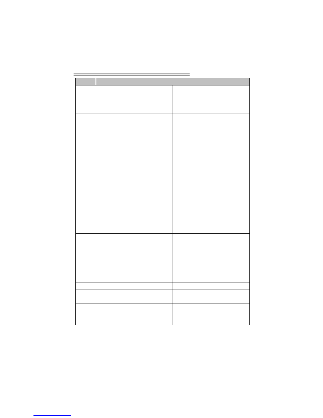
TF520 A2+/TF560 A2+
59
TF520 A2+ TF560 A2+
サウンド
Codec
ALC888 (Ver 5.x) / ALC662 (Ver 6.x)
7.1チャンネル オーディオ アウ ト (ALC888)
5.1チャンネル オーディオ アウ ト (ALC662)
ハイデフィニ ションオー ディ オのサポー ト
ALC888 (Ver 5.x) / ALC662 (Ver 6.x)
7.1チャンネル オーディオ アウ ト (ALC888)
5.1チャンネル オーディオ アウ ト (ALC662)
ハイデフィニ ションオー ディ オのサポー ト
PCIスロット x3 PCIス ロット x3
PCI Express x16スロット x1 PCI Express x16スロット x1 スロット
PCI Express x 1スロット x2 PCI Express x 1スロット x2
フロッピーコ ネクタ x1 フロッピーコネク タ x1
プリンタポー トコネクタ x1 プリンタポー トコネクタ x1
IDE コネクタ x1 IDEコネク タ x1
SATAコネクタ x4 SATAコネクタ x4
フロントパネ ルコネクタ x1 フロントパネ ルコネクタ x1
フロントオー ディオコネ クタ x1 フロントオー ディオコネ クタ x1
CDインコネクタ x1 CDインコネクタ x1
S/PDIFアウトコネ クタ x1 S/PDIFアウトコネクタ x1
CPUファンヘッダ x1 CPUファンヘッダ x1
システムファ ンヘッダ x2 システムファ ンヘ ッダ x2
CMOSクリアヘッダ x1 CMOSクリアヘッダ x1
USBコネク タ x2 USBコネクタ x2
電源コネクタ (24 ピン) x1 電源コ ネクタ(24 ピン) x1
オンボードコ
ネクタ
電源コネクタ (4ピン) x2 電源コ ネクタ(4ピン) x2
背面パネル
I/O
PS/2キーボード x1
PS/2マウス x1
シリアルポー ト x1
LANポート x1
USBポート x6
オーディオジ ャック(V er 5.x ) x6
オーディオジ ャック(V er 6.x ) x3
PS/2キーボード x1
PS/2マウス x1
シリアルポー ト x1
LANポート x1
USBポート x6
オーディオジ ャック(V er 5.x ) x6
オーディオジ ャック(V er 6.x ) x3
ボードサイズ 244 mm (幅) X 305 mm (高さ) 244 mm (幅) X 305 mm (高さ)
特殊機能
NVIDIA nTunes
RAID 0 / 1 / 0+1のサ ポー ト
NVIDIA nTunes
RAID 0 / 1 / 0+1 / 5 の サポー ト
OSサポー ト
Windows 2K / XP / V ISTA
Biostarは事前の サポートな しにOSサ ポートを追 加ま
たは削除する 権利を留保 しま す。
Windows 2K / XP / V ISTA
Biostarは事前の サポートな しにOSサ ポートを追 加ま
たは削除する 権利を留保 しま す。
2007/05/21
Page 62

TF520 A2+/TF560 A2+ BIOS Manual
i
BIOS Setup ................................................................................................ 1
1 Main Menu ............................................................................................. 3
2 Standard CMOS Features..................................................................... 7
3 Advanced BIOS Features ...................................................................... 9
4 Advanced Chipset Features................................................................. 16
5 Integrated Peripherals......................................................................... 18
6 Power Management Setup................................................................... 25
7 PnP/PCI Configurations...................................................................... 29
8 PC Health Status .................................................................................. 32
9 Over Clock Navigator.......................................................................... 35
10 CMOS Reload Program (C.R.P.)...................................................... 42
Page 63

TF520 A2+/TF560 A2+
1
BIOS Setup
Introduction
The purpose of this manual is to describe the settings in the Phoenix-Award™
BIOS Setup program on this motherboard. T he Setup program allows users to
modify the basic system co nfiguratio n and save these settings to CMOS RAM.
The power of CMOS RAM is supplied b y a battery so that it retains the Setup
info rmat ion when the po wer is turned off.
Basic Inp ut-O utput Sys tem (BIOS) d et er mines what a co mput er can do without
access ing programs from a disk. This system controls most of the input and
outp ut devic es suc h as keybo ard, mous e, serial ports a nd d isk drives. BI OS
activates at the firs t stage of the booting process, loading and executing the
operating system. Some additional features, such as virus and password
protectio n or chipset fine-tuning options are also included in BIOS.
The rest of this manual will to guide you through the options and settings in
BIOS Setup.
Plug and Pla y Support
This PHO ENIX-AWARD BIOS suppo rts t he Plug and Play Vers io n 1. 0A
spec ification and ESCD (Extended System Configuration Data) write.
EPA Green PC Support
This PHOENIX-AWARD BIOS supports Version 1.03 o f the EPA Green PC
spec ification.
APM Support
This PHOENI X-AW ARD BIO S suppo rts Version 1.1& 1.2 of t he Adva nc ed
Power Management (APM) specification. Power management features are
implemented via the System Management Interrupt (SMI). Sleep and Suspend
power management modes are supported. Power to the hard disk drives and
video monitors can also be managed by this PHOENIX-AWARD BIOS.
Page 64

TF520 A2+/TF560 A2+
2
ACPI Support
Pho enix-Award ACPI BIOS support Version 1.0b of Advanced Configuration
and Power interface specification (ACPI). It provides ASL code for power
management and device configuration capabilit ies as defined in the ACPI
specification, developed by Microsoft, Intel and Toshib a.
PCI Bus Support
This PHO ENIX-AWARD BIOS also s upports Version 3.0 of the Intel PCI
(Peripheral Component Interconnect) local bus specific atio n.
DRAM Support
DDR SDRAM (Double Data Rate Synchronous DRAM) is supported.
Supported CPUs
This PHOENIX-AWARD BIOS supports the AMD CPU.
Using Setup
Use the arrow keys to highlight items in most of the place, p res s <Enter> to
select, use the <PgUp> and <PgDn> keys to change entries, press <F1> for help
and p ress <Esc> to quit. The following table provides more d etail about how to
navigate in the Setup p rogra m by using the k eybo ard.
Keystroke Function
Up arrow Move to p revio us item
Down arrow Move to next item
Left arro w Move to the item o n the left (menu bar )
Right arrow Move to the item o n the ri ght (me nu bar)
Move Enter Move to the item you desired
PgUp key Increase the numeric value or make changes
PgDn key Decrease the numeric value or make changes
+ Key Increase the numeric value or make c hanges
- Key Decrease the numeric value or make changes
Esc key Main Menu – Quit a nd not save changes into CMOS
Status Page Setup Menu and Option Page Setup Me nu – Exit
Current page and return to Main Menu
F1 key General help on Setup navigation keys
F5 key Load previous values from CMOS
F7 key Load the optimized defaults
F10 key Save all the CMOS cha nges and exit
Page 65

TF520 A2+/TF560 A2+
3
1 Main Menu
Once yo u enter Phoenix-Award BIOS™ CMOS Setup Utility, the Main Menu
will appear on the screen. The Main Menu allows you to s elect from several
setup functions. Use the arrow keys to select among the items and press <Enter>
to accept and enter the s ub-menu.
Figure 1: Main Menu
Stan dard CMO S Fe atures
This submenu contains industry standard configurable options.
Advanced BIOS Features
This submenu allo ws yo u to conf igure ad vanc ed features o f the BIOS.
!! WARNING !!
For better system performance, the BIOS firmware is being
continuo us ly upd ated. The BI OS info rmat io n d escrib ed in
this manual (Figure 1, 2, 3, 4, 5, 6, 7, 8, 9) is fo r yo ur
reference only. The actual BIOS information and settings on
board may be slightly different from this manual.
Page 66
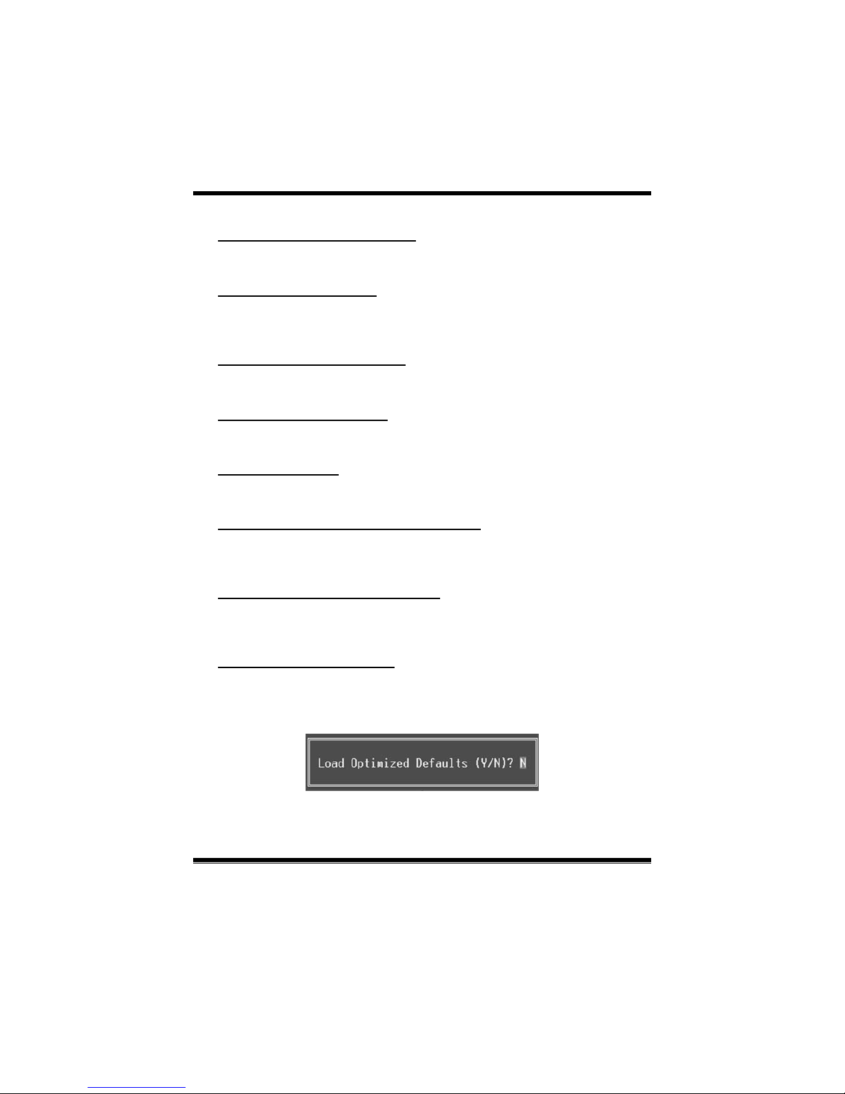
TF520 A2+/TF560 A2+
4
Advanced Chipset Features
This submenu allows you to configure special chipset features.
Integrated Peripherals
This s ub menu allo ws you to configure certain IDE hard dr ive optio ns and
Programmed Input/ Output features.
Power Management Setup
This submenu allows you to configure the power management features.
PnP/PCI Configurations
This submenu allows you to configure certain “Plug and Play” and PCI options.
PC Health Status
This submenu allo ws yo u to monito r the hardwar e of yo ur s yst em.
OverClock Navigator Engine (O.N.E.)
ONE provides two powerful overclock engines, MOS & AOS for both
overclock expertise and beginner.
CMOS Reload Program (C.R.P.)
The CMOS Reload Pro gram (CRP) allows yo u to save different CMOS s ettings
into BIOS-ROM.
Load Optimized Defaults
This selection allo ws you to reload the BIOS when problem occurs during
system booting sequence. These configurations are factory settings optimized
for this syst em. A confirmat ion message will be displayed before defaults are
set.
Page 67
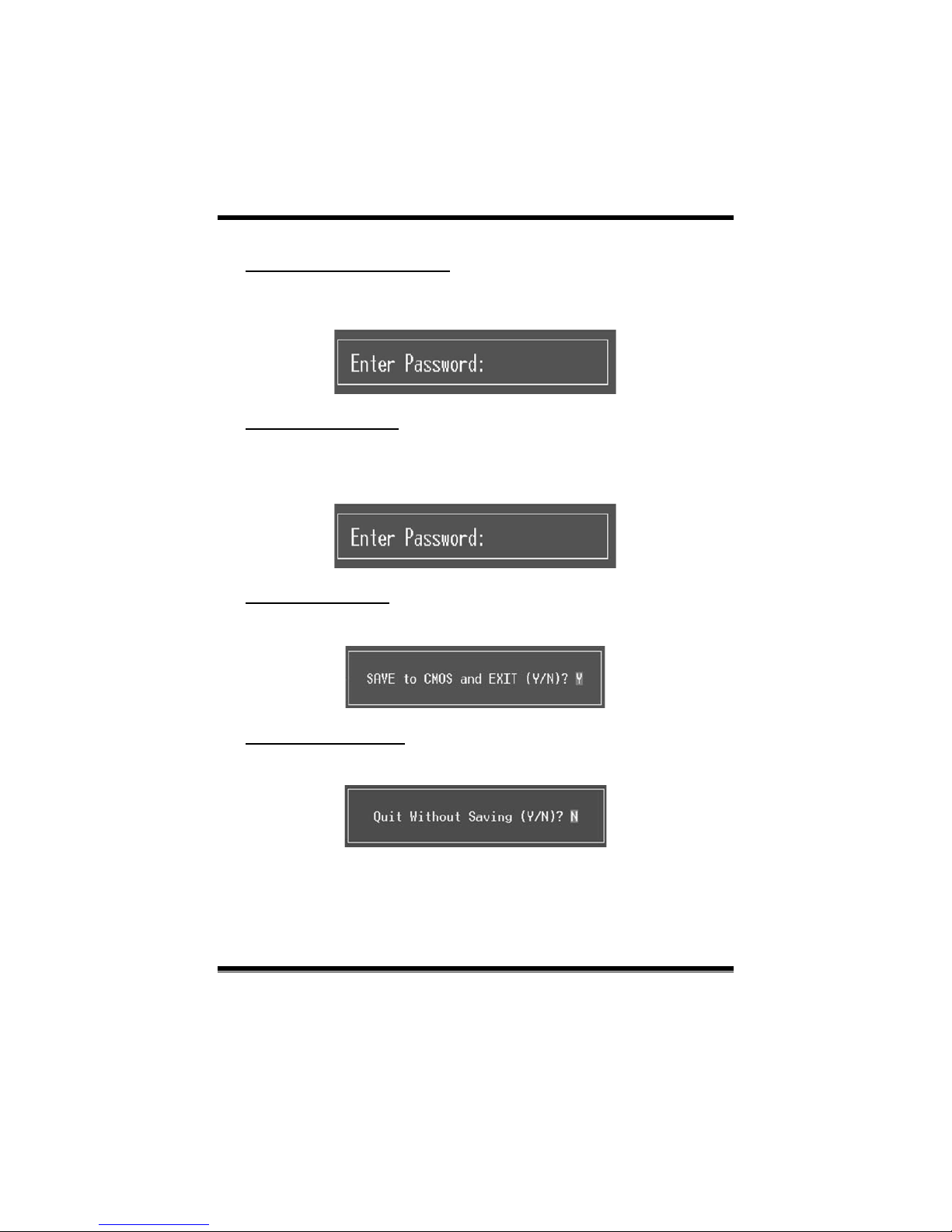
TF520 A2+/TF560 A2+
5
Set Supervisor Password
Setting the sup ervisor pass word will prohibit everyone except the supervisor
from making changes us ing the CMOS Setup Utility. You will b e pro mpted with
to ent er a pass word.
Set User Password
If the Supervisor P assword is not set, then the User Password will func tio n in
the s ame way as th e Super visor Pass wo rd. If t he S uperviso r Password is set and
the User P ass word is set, the “User” will only be able to view configurations but
will not be able to change them.
Save & Exit Setup
Save all configuration changes to CMOS (memory) and exit setup. Confirmation
message will be displayed before proceeding.
Exit Without Saving
Abandon all changes made d uring the current session and exit setup.
Confirmation mess age will be displayed before p roceeding.
Page 68
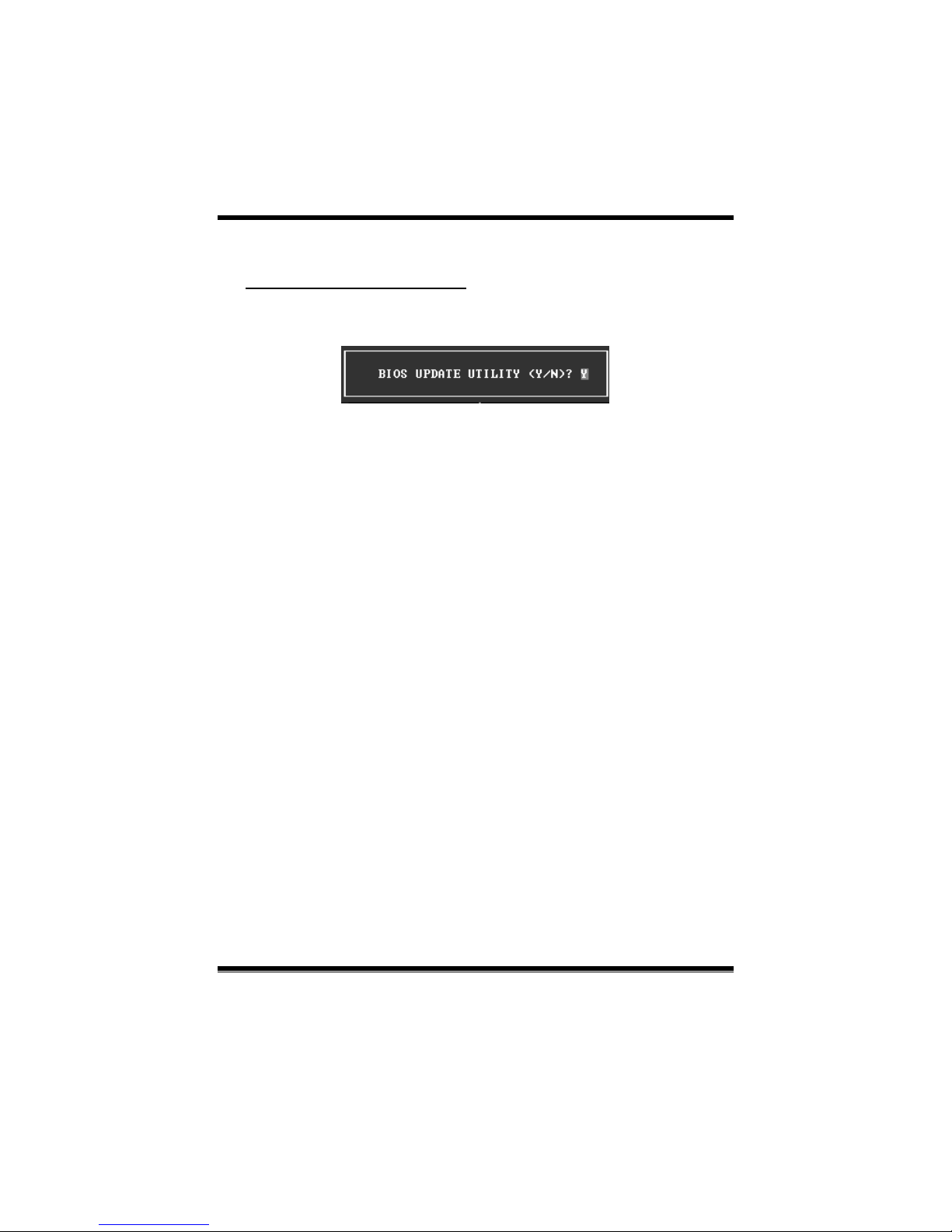
TF520 A2+/TF560 A2+
6
Integrate Flashing Program
This is a very s af e way to upgr ad e BIOS.
By pressing “ Enter” key for three times, and the upgrading process will be
completed easily.
Page 69
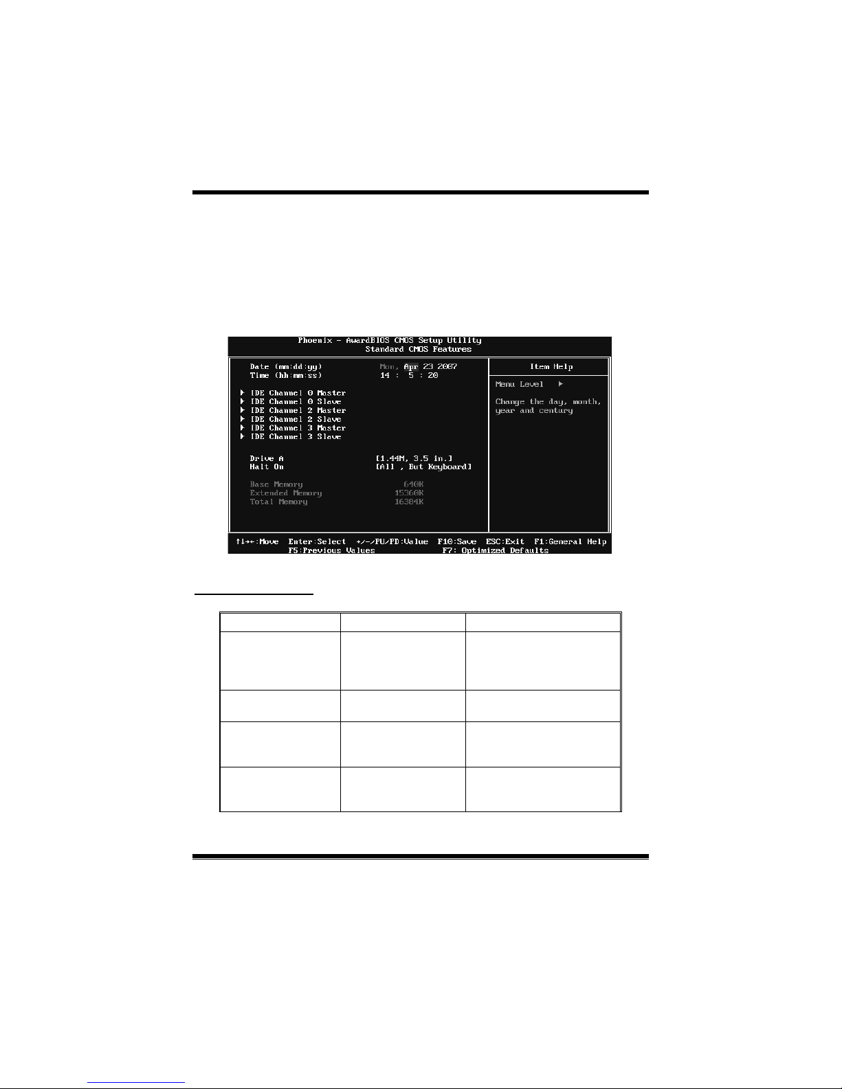
TF520 A2+/TF560 A2+
7
2 Standard CMOS Features
The items in Standard CMOS Setup Menu are divided into s everal categories.
Each cate gory inc lud es no, one or mo re than one setup it ems. Us e the arrow
keys to highlight the item and then use the<P gUp> or <Pg Dn> keys to select the
value you want in each item.
Figure 2: Standard CMOS Setup
Main Menu Selections
This table shows the items and the available options on the Main Menu.
Item Option s Description
Date mm : dd : yy
Set the system date. Note
that the ‘Day’ automatically
changes when you set the
date.
Time hh : mm : ss
Set the system internal
clock.
IDE Channel 0/2/3
Master
Options are in its sub
menu.
Press <Enter> to enter the
sub menu of detailed
options
IDE Channel 0/2/3
Slave
Options are in its sub
menu.
Press <Enter> to enter the
sub menu of detailed
options.
Page 70

TF520 A2+/TF560 A2+
8
Item Option s Description
Drive A
360K, 5.25 in
1.2M, 5.25 in
720K, 3.5 in
1.44M, 3.5 in
2.88M, 3.5 in
None
Select the type of floppy
disk drive installed in your
system.
Halt On
All Errors
No Errors
All, but Keyboard
All, but Diskette
All, but Disk/ Key
Select the situation in which
you want the BIOS to stop
the POST process and
notify you.
Base Memory N/A
Displays the amount of
conventional memory
detected during boot up.
Extended Memory N/A
Displays the amount of
extended memory detected
during boot up.
Total Memory N/A
Displays the total memory
available in the system.
Page 71
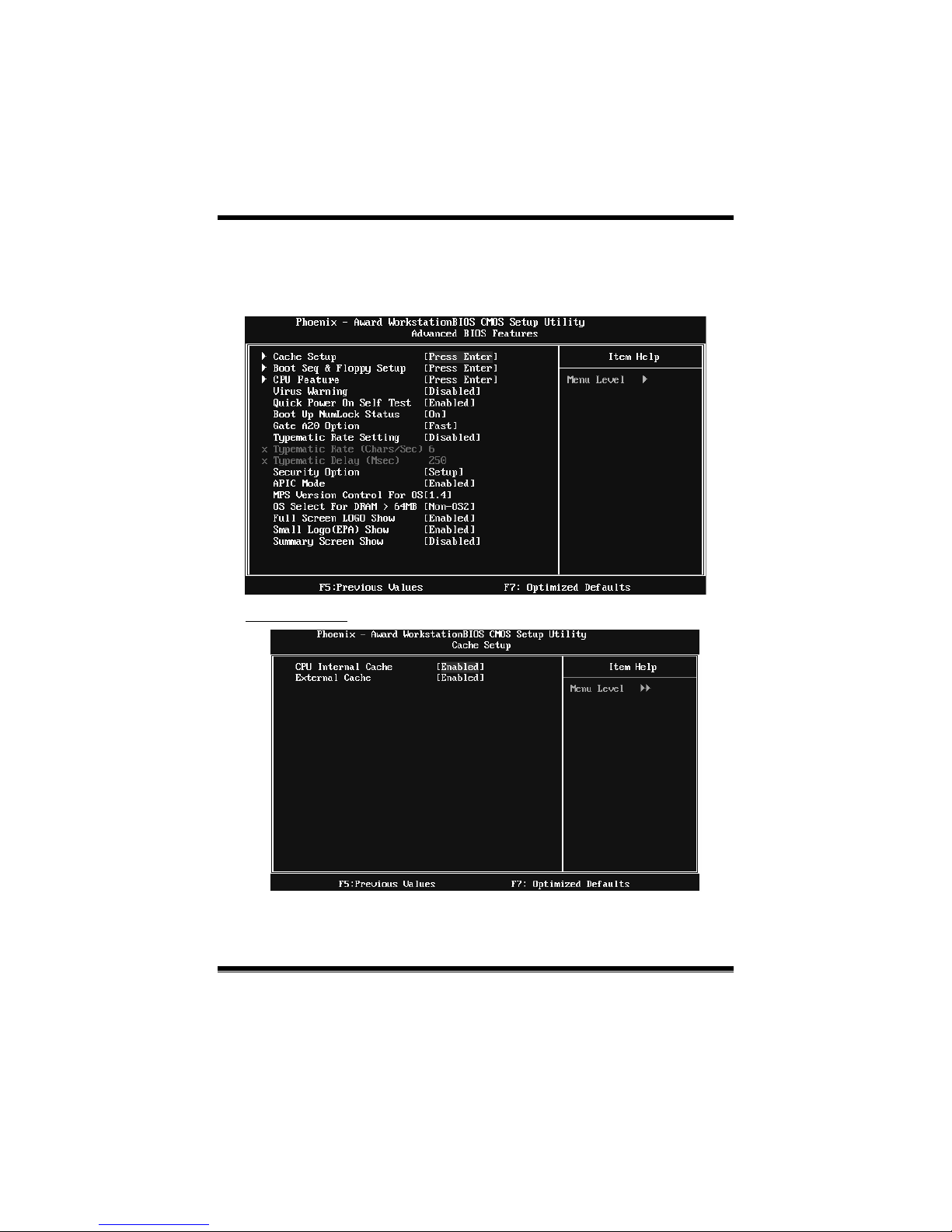
TF520 A2+/TF560 A2+
9
3 Advanced BIOS Features
Figure 3: Advanced BIOS Setup
Cache Setup
Page 72

TF520 A2+/TF560 A2+
10
CPU Internal Cache
Depending on the CPU/chipset in use, you may be able to increase memory
ac cess tim e with this opt io n.
Enable d (default) Enable cache.
Disab led Disab le cache.
External Cache
This option enables or d isables “Level 2” secondary cache on the CPU, which
may improve performance.
Enable d (default) Enable cache.
Disabled Disable cache.
Boot Seq & Floppy Setup
This item allows you to setup boot sequence & Floppy.
Page 73
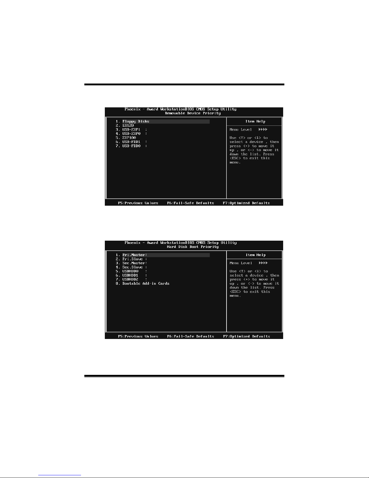
TF520 A2+/TF560 A2+
11
Removable Device Priority
Select Removable Boot Device Priority.
The Choices: Flopp y Dis ks, Zip 1 00, USB-FDD0, US B-F DD1, US B-ZIP 0,
USB-ZIP 1, LS 120.
Hard Disk Boot Priority
The BIOS will attempt to arrange the Hard Disk boot sequence automatically.
You can change the Hard Disk booting s equence here.
The Choices: Pri. Master, Pri. Slave, Sec. Master, Sec. Slave, USB HDD0, USB
HDD1, USB HDD2, and Bootable Add-in Cards.
Page 74
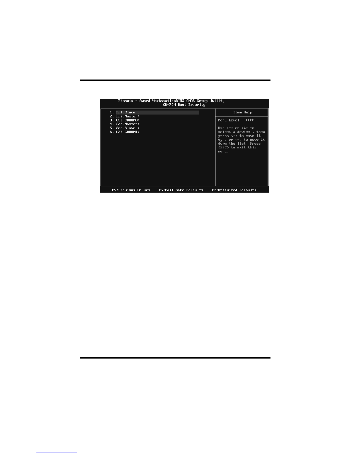
TF520 A2+/TF560 A2+
12
CD-ROM Boot Priority
The Choices: P ri. Master, Pri. Slave, Sec. Master, Sec. Slave, USB-CDROM0,
USB-CDROM1.
First/Second/Third Boot Device
The BIOS will attempt to load the operating system in th is order.
The Choices: Removable, Hard Disk, CDROM, Legacy LAN, Disab led.
Boot Other Device
When enabled, BIOS will try to load the operating system from other device
when it failed to load from the three devices above.
The Choices: Enabled (default), Disabled
Boot Up Floppy Seek
When enabled, System will test the floppy dr ives to determine if they have 40
or 80 tracks during boot up. Disabling this option reduces the time it takes to
boot-up.
The Choices: Enabled (default), Disabled.
Page 75
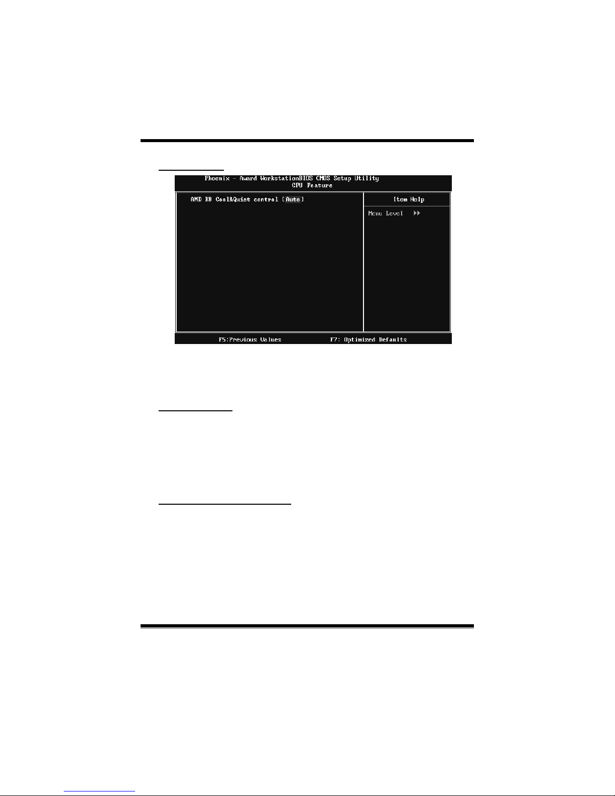
TF520 A2+/TF560 A2+
13
CPU Feature
AMD K8 Co o l&Quiet con tr o l
The item allows you select K8 Cool’n’Quiet control.
The Choices: Auto (default), Dis abled.
Virus Warning
This option allows you to choose the VIRUS Warning featur e that is used to
protect the IDE Hard Disk boot sector. If this function is enabled and an attempt
is made to write to the boot sector, BIOS will display a warning message on the
screen and sound an alarm beep.
Disabled (default) Virus protectio n is disabled.
Enabled Virus protectio n is activated.
Quick Power On Self Test
Enabling this option will cause an abridged version of the Power On Self-Test
(POS T) to execut e aft er yo u power up the comput er.
Disabled Normal POST.
Enabled (def ault) Enab le quic k POST.
Page 76

TF520 A2+/TF560 A2+
14
Boot Up NumLock Status
Selec ts the NumLoc k S t ate after the s ystem switc hed o n.
The Choices:
On (default) Nu mp ad is n umb er keys .
Off Numpad is arrow keys.
Gate A20 Option
Select if chipset or keyboard controller should control Gate A20.
Normal A pin in the keyboard contro ller controls GateA20.
Fast (default) Lets chips et co ntrol Gate A20.
Typematic Rate Setting
When a key is held down, the keystroke will rep eat at a rate determined by the
keybo ard controller. When enabled, the typematic rate and typematic delay can
be configured.
The Choices: Disabled (default ), Enabled.
Typematic Rate (Chars/Sec)
Sets the rat e at whic h a ke ystroke is repeat ed when you hold the key do wn.
The Choices: 6 (d efault), 8, 10, 12, 15, 20, 24, 30.
Typematic Delay (Msec)
Sets the delay time after the key is held down before it begins to rep eat the
keystroke.
The Choices: 250 (default), 500, 750, 1000.
Security Option
This option will enable only individuals with passwords to b ring the system
online and/or to use the CMOS Setup Utility.
System: A password is required for the system to boot and is also
required to acc ess the Setup Utility.
Setup (default): A p ass word is required to acc ess t he Setup Utility o nly.
This will o nly apply if p ass words are set from the Setup main menu.
Page 77

TF520 A2+/TF560 A2+
15
APIC MOD E
Selecting Enabled enables APIC device mode reporting from the BIOS to the
operating sys tem.
The Choices: Enabled (default), Disabled.
MPS Version Control For OS
The BIOS supports version 1.1 and 1.4 of the Intel multiprocessor specification.
Selec t vers io n s upport ed by the operat io n sys tem running on this co mputer.
The Choices: 1.4 (default), 1.1.
OS Select For DRAM > 64MB
A choice other than Non-OS 2 is o nly used for OS 2 systems with memory
exceeding 64MB.
The Choices: Non-OS2 (def ault), OS2.
Full Screen LOGO Show
This item allows you to enable/disable Full Screen LOGO Show.
The Choices: Enabled (default), Disabled.
Small Logo(EPA) Show
This item allows you to selec t whether the “S mall Lo go” shows. Enabled
(default) “Small Logo” shows when system boots up. Disabled No “Small
Logo” shows when system boots
The Choices: Enabled (default), Disabled.
Summary Screen Show
This item allows you to enable/disab le the summary screen. Summary screen
means system configuration and PCI device listing.
The Choices: Disabled (default ), En abled.
Page 78
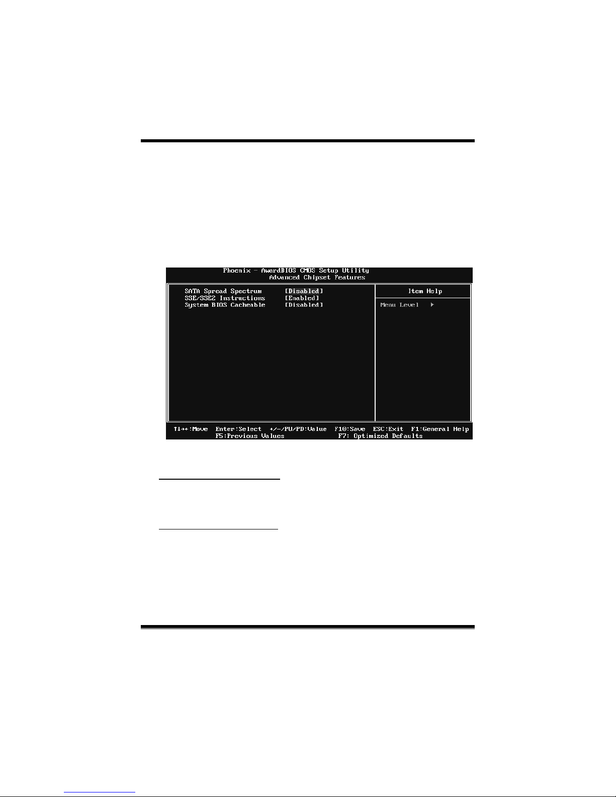
TF520 A2+/TF560 A2+
16
4 Advanced Chipset Features
This submenu allo ws you to configure the specific features of the chipset
installed on your system. This chipset manage bus speeds and access to system
memory resources, such as DRAM. It also coordinates communications with the
PCI b us. The default settings that came with your system have been optimized
and t herefore s hould not be changed unless you are suspicious that the sett ings
have b een changed incorrectly.
Figure 4: Advanced Chipset Setup
SATA Spread Spectrum
This item allows you to enable/disable the Spread Spectrum functio n.
The Choices: Disabled (default ), Enabled.
SSE/SSE2 instructions
This item allows you to enable/disable SS E/SS E2 instruction.
The Choices: Enabled (default), Dis abled.
Page 79

TF520 A2+/TF560 A2+
17
System BIOS Cacheable
Selec ting the “Enab led ” option allows c aching o f th e system BIOS ROM at
F0000h-FFFFFh, which is able to improve the system performanc e. However,
any programs that attempts to write to this memory block will cause conflicts
and result in system errors.
The Choices: Disabled (default ), Enabled.
Page 80
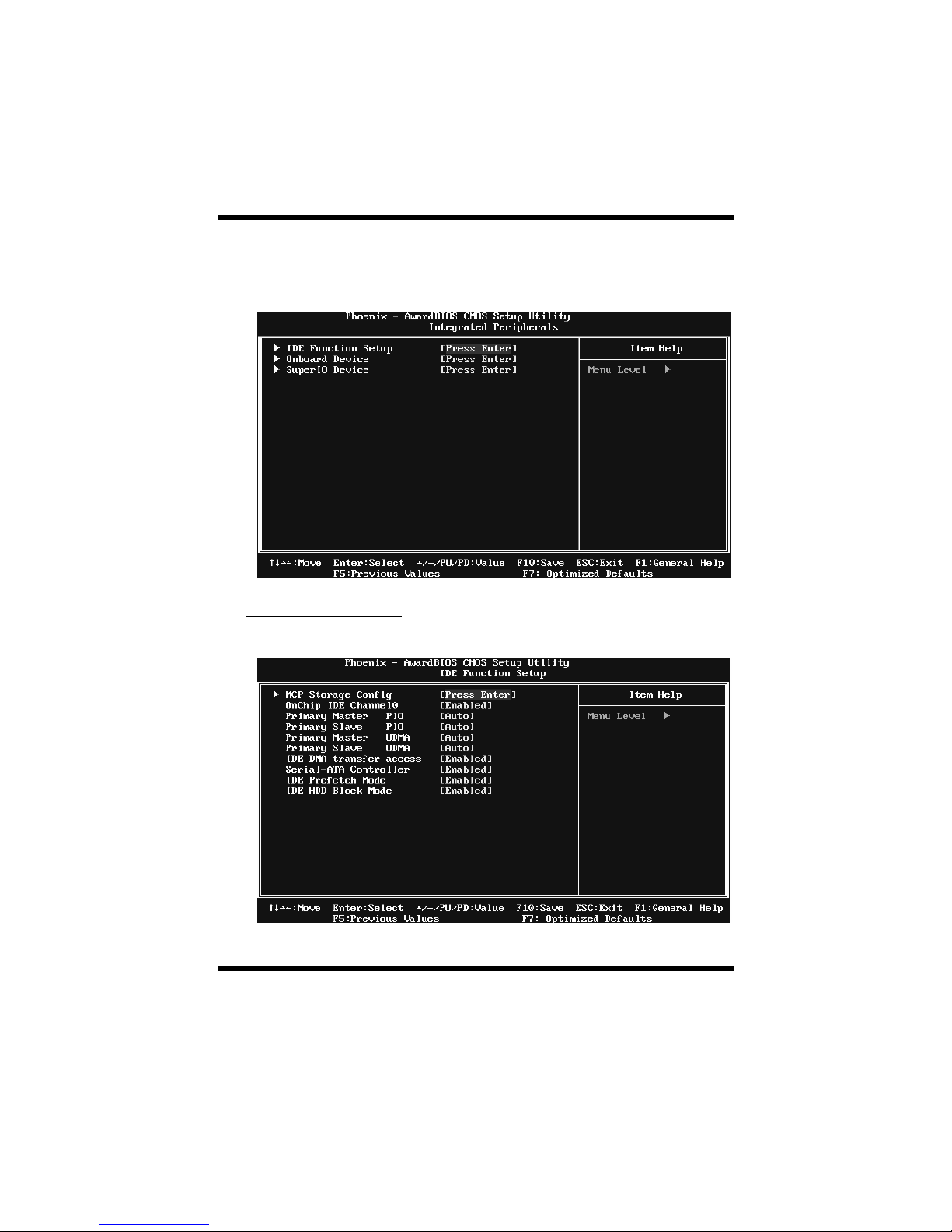
TF520 A2+/TF560 A2+
18
5 Integrated Peripherals
Figure 5. Integrated Peripherals
IDE Function Setup
Highlight the “Press Enter” lab el next to the “IDE Function Setup” label and
press enter key will take you a submenu with t he fo llo wing opt ions:
Page 81
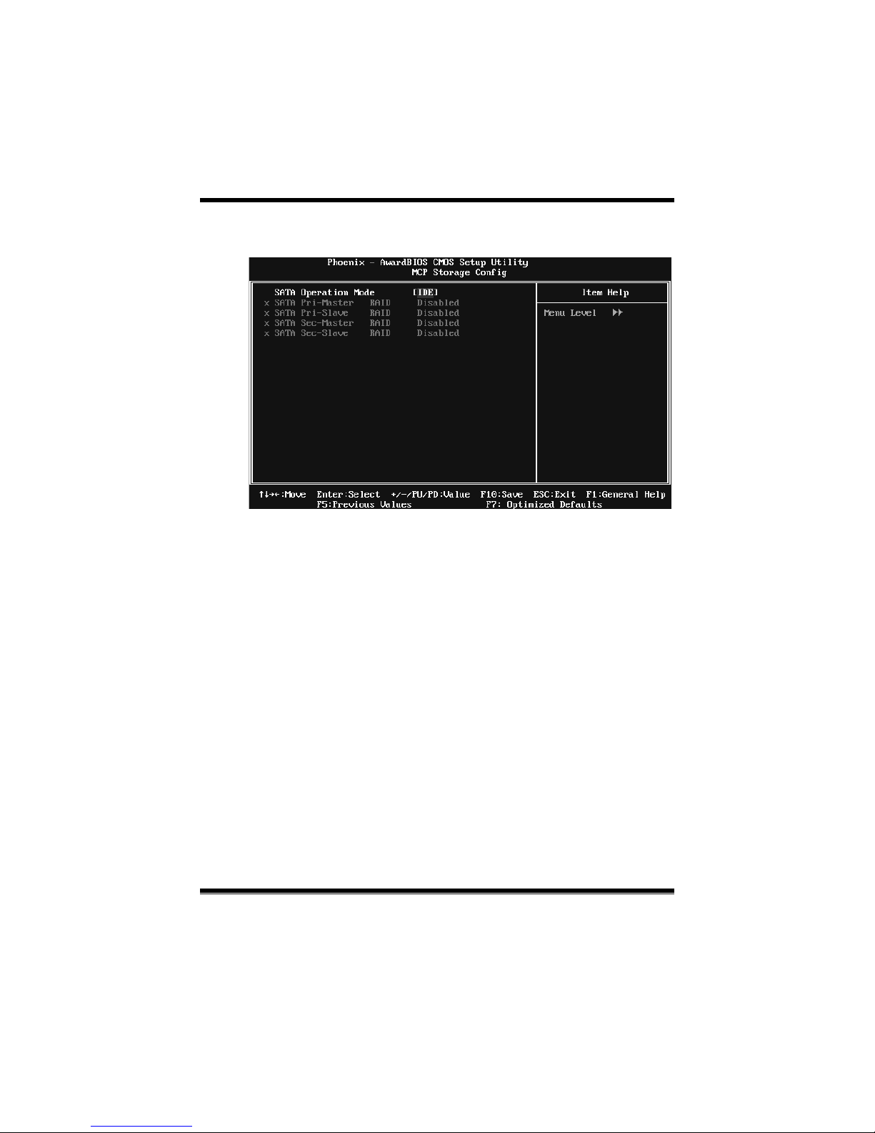
TF520 A2+/TF560 A2+
19
MCP Storage Config
SATA Operation Mode
This option allows you to choose SATA function.
The Choices: IDE (default), RAID, AHCI.
SATA Pri-/Sec- Master/Slave RAID
This option allows you to enable or disable SATA Primary/Secondary RAID.
The Choices: Disabled (default), Enabled.
OnChip IDE Cha nne l 0
The motherboard chipset contains a P CI IDE interface with support for two
IDE channels. Select “Enabled” to activate the first and/or second IDE interface.
Select “Disabled” to deactivate an interface if you are going to install a primary
and/or secondary add-in IDE interface.
The Choices: Enabled (default), Disabled.
Primary Master/Slave PIO
The IDE PIO (Programmed Input / Output) fields let you set a PIO mode (0-4)
for each of the IDE devices that the onboard IDE interface supports. Modes 0
to 4 will increase performance progressively. In Auto mode, the system
automatically determines the best mode for each device.
The Choices: Auto (default), Mode0, Mode1, Mode2, Mode3, Mode4.
Page 82

TF520 A2+/TF560 A2+
20
Primary Master/Slave UDMA
Ultra DMA function can be implemented if it is supported by the IDE hard
drives in your system. As we ll, your operating environment requires a DMA
driver (Windows 95 or OSR2 may need a third party IDE bus master driver). If
your hard drive and your system software both support Ultra DMA, select Auto
to enable BIOS support.
The Choices: Auto (default), Disabled.
IDE DMA Transfer Access
This item allows you to enable or disable the IDE DMA transfer access.
The Choices: Enabled (default), Disabled.
Serial-ATA Controller
This item allows you to enable or disable the SATA controller.
The Choices: Enabled (default), Disabled.
IDE Prefetch Mode
The “onboard” IDE drive interfaces supports IDE prefetch function for faster
drive access. If the interface on your drive does not support prefetching, or if
you install a primary and/or secondary add- in IDE interface, set this opt ion to
“Disab led”.
The Choices: Enabled (default), Disabled.
IDE HDD Block Mode
Block mode is also called block transfer, multip le commands, or multiple
sectors read / write. If your IDE hard drive supports block mode (most new
drives do), select Enabled for automatic detect ion of the optimal number of
block mode (most new drives do), select Enabled for automatic detection of the
optima l number of block read / write per sector where the drive can support.
The Choices: Enabled (default), Disabled.
Page 83
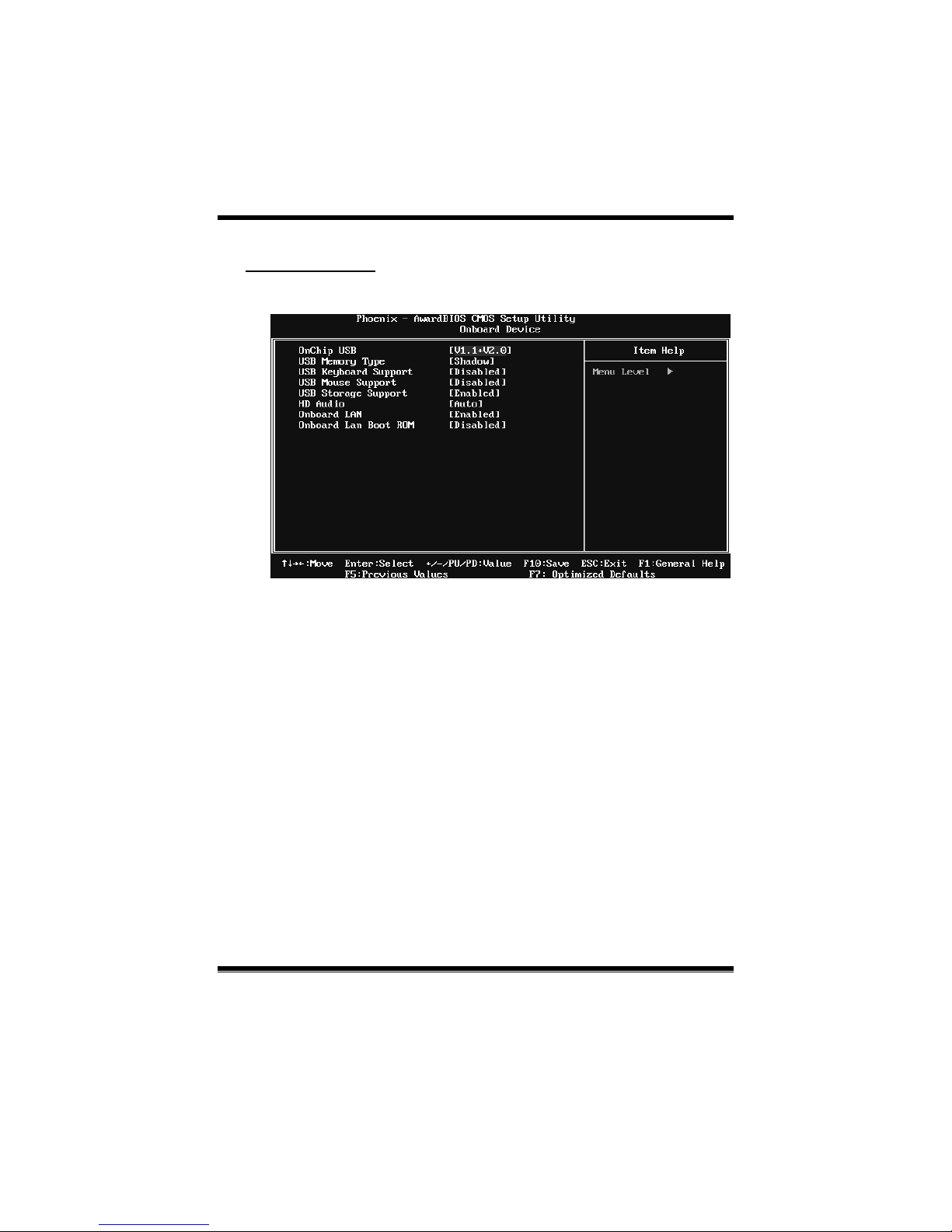
TF520 A2+/TF560 A2+
21
Onboard Device
Highlight t he “Press Enter” label next to the “Onboard Device” label and press
the enter key will take you a submenu with the following options :
OnChip USB
This option should be enabled if your system has a USB installed on the system
board. You may need to disable this feature if you add a higher performance
controller.
The Choices: V1.1+V2.0 (default), Disabled, V1.1
USB Memory Type
This option allows you to choose the USB memory type.
The Choices: SHADOW (default), Base Memory(640K).
USB Keyboard Support
This item allows you to enable or disable the USB Keyboard Legacy Support.
Enabled Enable USB Keyboard Support.
Disabled (default) Disab le USB Keyboard Support.
Page 84

TF520 A2+/TF560 A2+
22
USB Mouse Support
This item allows you to enable or disable the USB Mouse Legacy Support.
Enabled USB Mouse Support.
Disabled (default) Disab le USB Mouse Support.
USB Storage Support
This item allows you to enable or disable the USB storage device Legacy
Support.
Enable d (default) USB storage Support.
Disab led Disable USB storage Support.
HD Audio
This option allows you to control the onboard HD audio.
The Choices: Auto (default), Disabled.
Onboard LAN
This option allows you to control the onboard LAN.
The Choices: Enabled (default), Disabled.
Onboard LAN Boot ROM
This item allows you to enable or disable the Onboard LAN Boot ROM.
The Choices: Disabled (def ault ), Enab led.
Page 85

TF520 A2+/TF560 A2+
23
SuperIO Device
Press Enter to configure the Super I/O device.
Onboard FDC Controller
Select enabled if your system has a floppy disk controller (FDC) installed on
the system board and you wish to use it. If you installed another FDC or the
system uses no floppy drive, select disab led in this field.
The Choices: Enabled (default), Disabled.
Onboard Serial Port 1
Select an address and corresponding interrupt for the first and second serial
ports.
The Choices: 3 F8/IRQ4 (default), Disabled, 2F8/IRQ3, 3E8/IRQ4, 2E8/IRQ3,
Auto.
Onboard Parallel Port
This item allows you to determine access onboard parallel port controller with
which I/O Address.
The Choices: 378/IRQ7 (default), 278/IRQ5, 3BC/IRQ7, Disabled.
Page 86

TF520 A2+/TF560 A2+
24
Parallel Port Mode
This item allows you to determine how the paralle l port should function. The
default value is SPP.
The Choices:
SPP (def ault) Usin g Para llel port as Sta ndard Pr inte r P ort.
EPP Usin g P ara lle l P o rt as En h anced Pa r allel P ort.
ECP U sin g Par allel po rt as Ext ended Ca p abil it ies Port.
ECP +EPP Usin g P aralle l port a s ECP & EPP m od e.
ECP Mode Use DMA
Select a DMA Channel for the port.
The Choices: 3 (default), 1.
Page 87
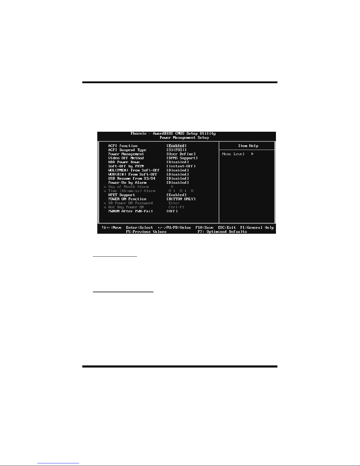
TF520 A2+/TF560 A2+
25
6 Power Management Setup
The Power Management Setup Menu allows you to configure your system to
utilize energy conservation and power up/power down features.
Figure 6. Power Manageme nt Setup
ACPI Function
This item displa ys the status of the Advanced Co nfigurat ion and Po wer
Management (ACPI).
The Choices: Enabled (default), Disabled.
ACPI Suspend Type
The item allo ws you to s elect the sus p end typ e u nder the ACPI operating
system.
The Choices: S1 (POS) (default) Power on Susp end
S3 (STR) S uspend to RAM
S1 & S3 POS+STR
Page 88

TF520 A2+/TF560 A2+
26
Power Management
This c ategory allo ws you to s elect the po wer saving method and is dir ectly
re la ted to t he fo llo wing mo d es :
1. HDD Po we r Do wn.
2. Susp end Mode.
There are three options of Power Management, three o f which have fixed mode
settings
Min. Power Saving
Minimum power management.
Suspend Mode = 1 hr.
HDD Power Down = 15 min
Max. Power Saving
Maximum power management only available for sl CPU’s.
Suspend Mode = 1 min.
HDD Power Down = 1 min.
Use r Define (d efault)
Allow you to set each op tio n individ ually.
Whe n you choos e user define, you can ad just each of the it em from 1 min. to 1
hr. excep t for HDD Power Down which ranges from 1 min. to 15 min.
Video Off Method
This option determines the manner when the monitor goes blank.
V/H SYNC+ Blank
This selection will cause the system to turn off the vertical and horizontal
synchronization ports and write blanks to the video buffer.
Blank Screen
This optio n only writes blanks to the vid eo buffer.
DPM S S u ppo rt (default)
Initial display power management signaling.
HDD Power Down
When enabled, the hard-disk drives will power down after a set time of system
inactivity. All other devices remain active.
The Choices: Disabled (d efault), 1 Min, 2 Min, 3 Min, 4 Min, 5 Min, 6 Min, 7
Min, 8 Min, 9 Min, 10 Min, 11 Min, 12 Min, 13 Min, 14 Min, 15Min.
Page 89

TF520 A2+/TF560 A2+
27
Soft-Off by PBTN
This item determines the behavior of system power button. Instant off turn off
the po wer immediat ely, and Delay 4 Sec. will require you to press and hold the
power button for 4 s eco nds to c ut off the system po wer.
The Choices: Delay 4 Sec, Ins tant-Off (default).
WOL(PME#)/ From Soft-Off
This item allo ws you to enable or disable Wake On LAN from Soft-Off
function.
The Choices: Disabled (default ), Enabled.
WOR(R I#) From Soft-Off
This item allows you to enable or disable Wake O n Ring from Soft-Off function.
The Choices: Disabled (default ), Enabled.
USB Resume From S3/S4
This item allows you to enable or disabled the USB resume from S3/S4
function.
The Choices: Disabled (default ), En abled.
Power-On by Alarm
This function is for setting date and time for your computer to boot up. When
enabled, you c a n choose t he date and time to b oo t up th e system.
The Choices: Disabled (default ), Enabled.
Date (of Month) Alar m
You c an c hoos e whic h month the sys t em wil l boot up.
Time (hh:mm:ss) Alarm
You can choose the system boot up time, input hour, minute and s econd to
specify.
Note: If you have c hange the setting, yo u must le t t he sys te m boot up until it
goes to the op erating s ystem, befo re this func tion wil l work.
HPET Support
This optio n allows you to d is abled or enables the High Precisio n Event T imer.
The Choices: Enabled (default), Dis abled.
Page 90

TF520 A2+/TF560 A2+
28
POWER ON Function
This item allows you to choose the power on method.
The Choices: Button Only(de fault), Pass wo rd, Hot Key, Mouse Move/Click,
Mouse Double Click, Any Key, Keyboard 98.
KB Power ON Password
Input password and press Enter to set the Keyboard power o n password.
Hot Key Power ON
Choos e the Hot Key co mbinatio n to boo t up the system.
The Choices : Ctrl-F1 (d efault), Ctrl-F2, Ctrl-F3, Ctrl-F4, Ctrl-F 5, Ctrl-F6,
Ctrl-F7, Ctrl-F8, Ctrl-F9, Ctrl-F10, Ctrl-F11, and Ctrl-F12.
POWER After PWR-Fail
This s etting sp ec if ies how your system should b ehave after a power fail or
interr upts occurs. By c hoos ing off wil l lea ve the co mp u ter in the power o ff s tate.
Choosing On will reboot the computer. Former-Sts will restore the system to the
status before po wer failure or interrupt occ urs.
The Choices: Off (default), On, Former-Sts.
Page 91
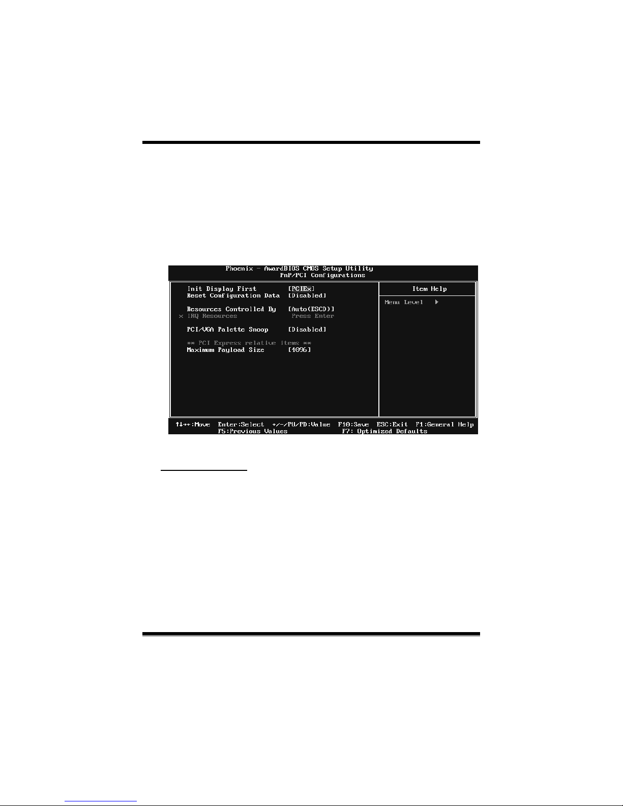
TF520 A2+/TF560 A2+
29
7 PnP/PCI Configurations
This section desc ribes configuring the PCI bus system. PCI, or Personal Computer
Inte rconnect, is a syst em which allows I/O devic es to oper ate at sp eeds ne aring the
speed of the CPU itself uses when communicating with its own special components.
This section covers some very technical items and it is strongly recommended that
only expe r ienc ed users s ho uld make a ny c hanges to the default settings.
Figure 7: PnP/PCI Configurations
Init Display First
This item allows you to decide to active whet her PCI Slot or on-chip VGA first.
The Choices: PCI Slot, PCIEx (default).
Page 92

TF520 A2+/TF560 A2+
30
Reset Configuration Data
The s ys tem BIOS s uppo rts t he P nP featur e whic h req uires the s yst em to reco rd
whic h resourc es are as s igned and pro tects reso urces fro m co nflict.
Every per iph eral devic e has a node, whic h is called ESCD. This nod e records
whic h resourc es are ass igned to it. The system needs to record and upda te ESCD
to the memory locations. These locations ar e reserv ed in the sys tem BIOS. If the
Disabled (default) option is chosen, the system‘s ESCD will update only when
the new c o nf ig uration var ies fro m the last one. If t he Enab led optio n is chosen,
the system is forc ed to updat e ESCDs and then is auto matically set to the
“Disabled ” mode.
The above settings will be shown on the screen o nly if “Manu al” is chosen for
the r es ourc es contro lled by funct io n.
Legac y is the t erm, which signif ies t hat a res ourc e is ass igned to the IS A Bus
and p rovid es non-PnP ISA add-o n c ards. PCI / IS A P nP s ignify that a reso urc e
is assigned to the PCI Bus or provides for ISA PnP add-on cards and
peripherals.
The Choices: Disabled (default ), Enabled.
Resources Controlled By
By Choos ing “Auto(ESCD)” (default), the system BIOS will detect the system
resources and automatically assign the relative IRQ and DMA channel for each
peripheral. By Choosing “Manual”, the user will need to assign IRQ & DMA for
add-on cards. Be sure that there are no IRQ/DMA and I/O port conflicts.
The Choices: Auto (ESCD) (default), Manual.
IRQ Resources
This submenu will allo w you to ass ign each system interrupt a type, depending
on the type of device using the interrupt. When you press the “Press Enter” tag,
you will b e d irect ed to a submenu that will allow you to conf igure the system
interrupts . T his is only configurable when “Resources Contro lled By” is set to
“Manual”.
IRQ-5 assigned to PCI Device
IRQ-7 assigned to PCI Device
IRQ-9 assigned to PCI Device
IRQ-10 assigned to PCI Device
IRQ-11 assigned to PCI Device
IRQ-14 assigned to PCI Device
Page 93

TF520 A2+/TF560 A2+
31
PCI / VGA Palett e Snoop
Some old graphic controllers need to “snoop” on the VGA palette and then map
it to their d isp lay as a way to provide boo t information and VGA compatibility.
This item allows such snooping to take place.
The Choices: Disabled (default ), Enabled
Ma xi mu m Pa ylo ad Size
Set t he maximum payload size fo r T ransac tio n pac kets (TLP).
The Choice: 4096 (default.), 128, 256, 512, 1024, 2048.
Page 94
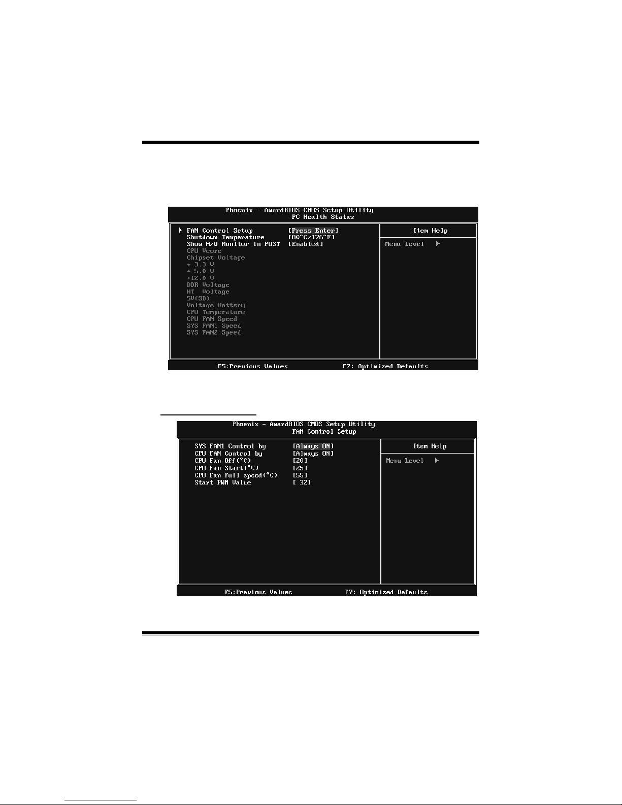
TF520 A2+/TF560 A2+
32
8 PC Health Status
Figure 8: PC Health Status
Fan Control Setup
Page 95

TF520 A2+/TF560 A2+
33
SYS FAN1 Control By
The Choice “smart” can make your northbridge FAN to reduce noise.
The Choices: Always ON (default), Smart.
CPU FAN Control By
The Choice “smart” can make your CPU FAN to reduce noise.
The Choices: Always ON (default), Smart.
CPU Fan Off<℃>
If the CPU Temperature is lower than the set value, FAN will turn off.
The Choices: Min=0,.Max=20, Key in a DEC number.
CPU Fan Start<℃>
CPU fan starts to work under smart fan function when arrive this set
value.
The Choices: Min=0,.Max=50, Key in a DEC number.
CPU Fan Full speed <℃>
Whe n CP U temper ature is reac h th e set value, the CP U fan will work
under Full Speed.
The Choices: Min=0,.Max=80, Key in a DEC number.
Start PWM Value
Whe n CP U temperatu re arrives to th e set value, the CPU fan will work
under Smart Fan Func t ion mod e. T he r ange is from 0~127, with an
interval of 1.
The Choices: Min=0,.Max=127, Key in a DEC number.
Shutdown Temperature
This item allows you to set up the CPU shutdo wn Temp erat ure. This item is
only effective under W indows 98 ACPI mode.
The C hoices: Disabled, 60℃/ 140℉, 65℃/ 149℉, 70℃/ 158℉, 75℃/ 167℉,
80℃/ 176℉ (Default), 85℃/ 185℉, 90℃/ 194℉.
Show H/W Monitor in POST
If you co mp ut er c o nt ains a mo nitoring syst em, it will show P C hea lt h status
during POST stage. The item offers several different delay times.
The Choices: Enabled (default), Disabled.
Page 96

TF520 A2+/TF560 A2+
34
CPU Vcore, Chipset Voltage, +3.3V, +5.0V, +12.0V, DDR
Voltage, HT Voltage, 5V<SB>, Voltage Battery
Detect the sys tem’s volt age status automatically.
CPU Temperature
This field disp lays the current temp er ature of CPU.
CPU FAN Speed
This field disp lays the current sp eed o f C P U fan.
SYS FAN1/FAN2 Speed
This field disp lays the current sp eed o f S YSTEM fan.
Page 97
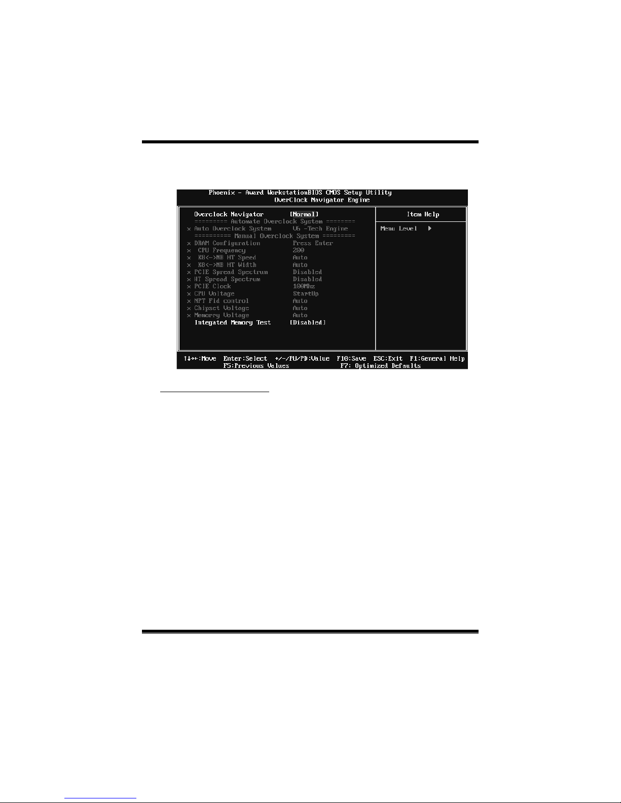
TF520 A2+/TF560 A2+
35
9 Over Clock Navigator
OverClock Navigator
OverClock .Navigator is designed for beginners in overcloc k field.
Bas ed on many test and experiments from Biostar Engineer Team, OverClock
Navigator provides 3 default overclock configurations that are able to raise the
system performance
The Choices: Normal (def ault), Auto mate Overclock, Manual Overc loc k
Page 98
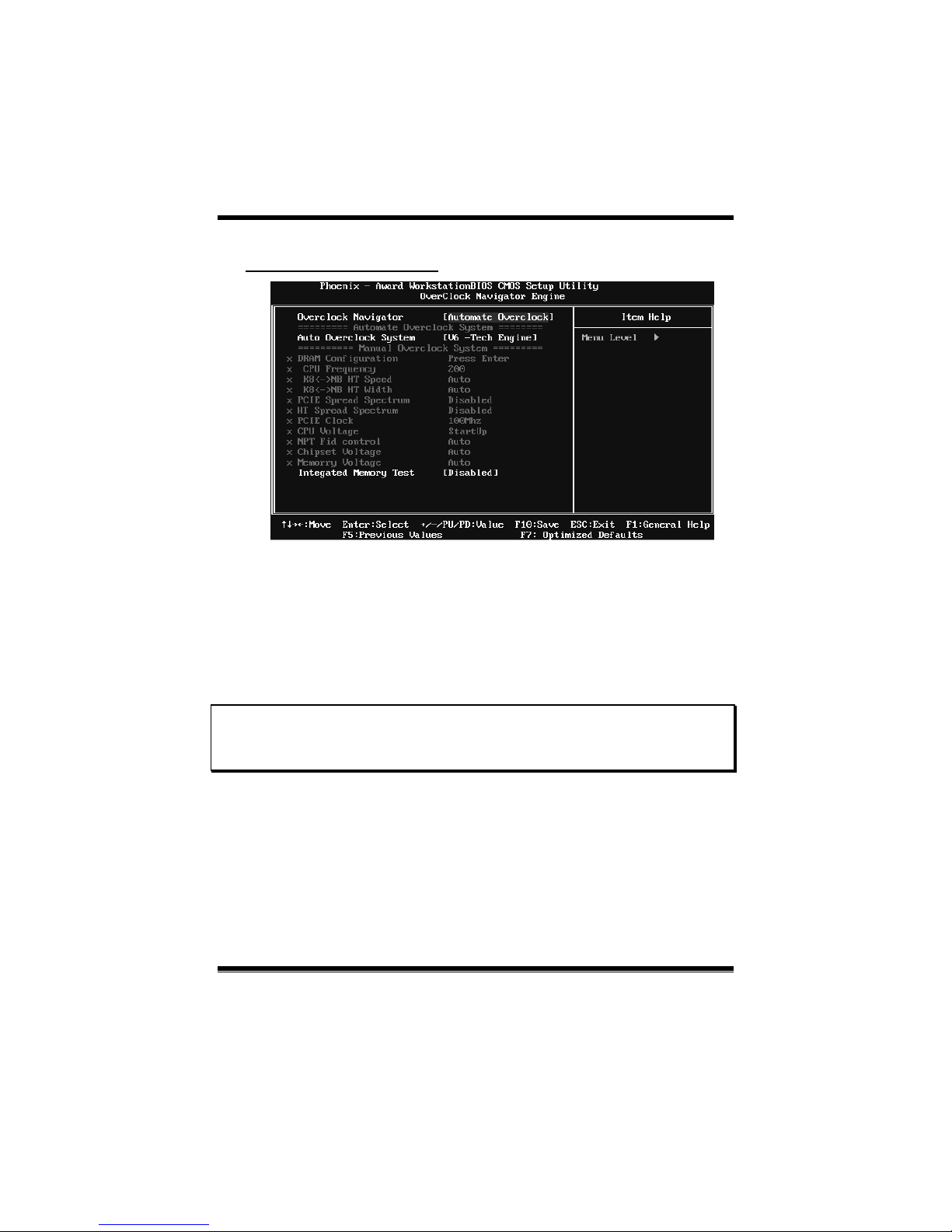
TF520 A2+/TF560 A2+
36
Auto OverClock System
The Overclock Navigator provides 3 different engines helping you to overclock
your system. These engines will boost your system performance to different
level.
The Choices:
V6 Tech Engine
This setting will raise about 5%~10% of whole system performance.
V8 Tech Engine
This setting will raise about 15%~25% of whole system p erformanc e.
V12 T ech Engine
This setting will raise about 25%~30% of whole system p erformanc e.
Cautions:
1. Not every AMD CPU performs the above overclock setting idea lly; the difference may vary
with the inst a lled C P U mod e l.
2. From BET exper im ent, th e Atho lo n64 FX CP U is not s uitable f o r this A.O.S. fea tu re.
Page 99
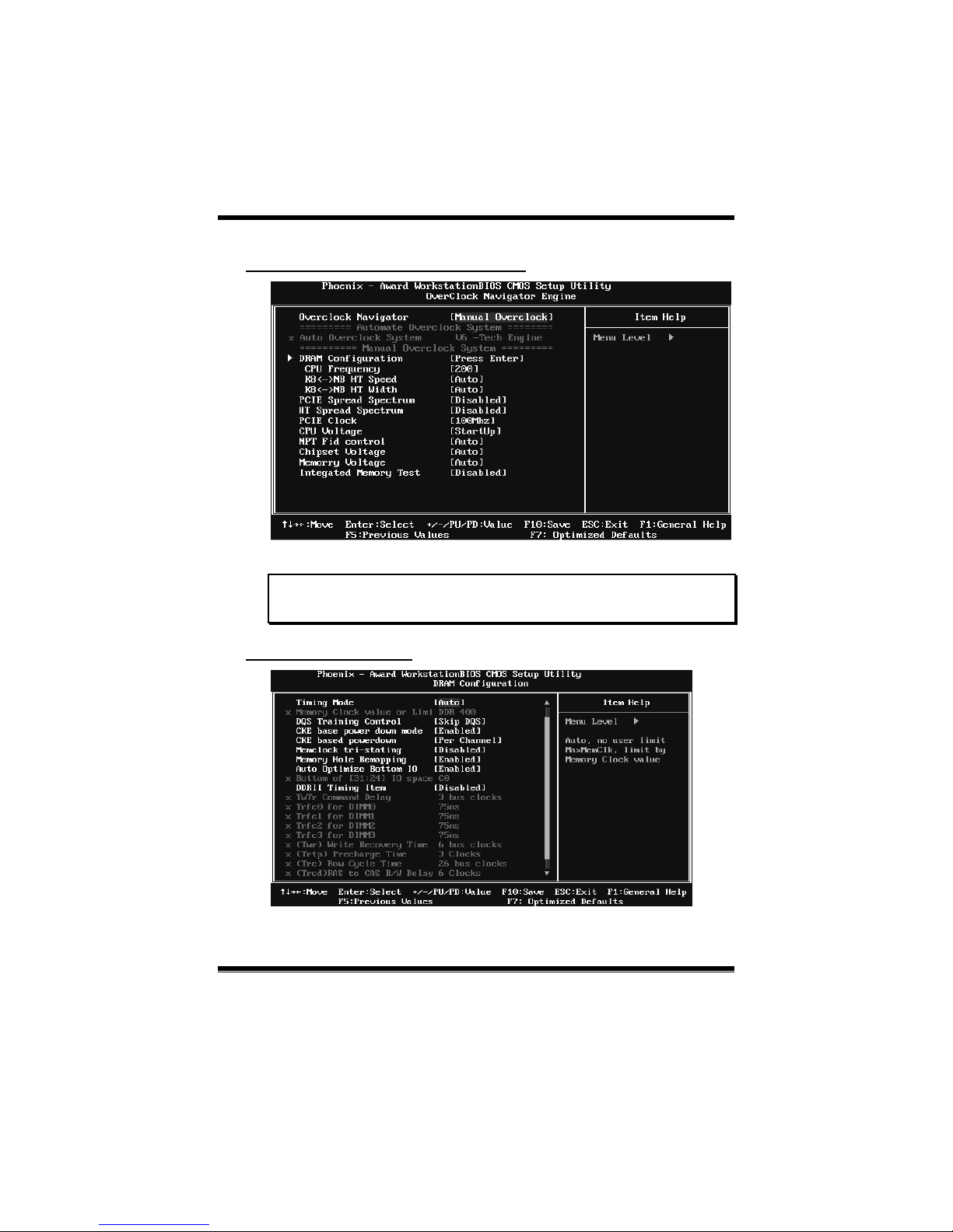
TF520 A2+/TF560 A2+
37
Manual Overclock System (M.O.S.)
MOS is designed for experienced overclock users.
It allows users to customize personal overclock setting.
Note:
Based on our test results; the overclock function achieved the best performance on AMD
3000+ CP U
DRAM Configuration
Page 100

TF520 A2+/TF560 A2+
38
Timing Mode
T his item a llow s you to c hoose to man u ally or au tomatica lly re gu late the DDR
Timing.
The Choices: Auto (def ault), MaxMem C lk.
Memory Clock Value OR Limi
The Choices: DDR 400 (default), DDR 533, DDR 667, DDR 800.
DQS Training Control
The Choices: P erform DQS, Skip DQS (default).
CKE base power down mode
The Choices: Disabled (def ault ), Enab led.
CKE based power down
The Choices: Per Channel (default), Per CS.
Memclock tri-stating
The Choices: Disabled (default), Enabled.
Memory Hole Remapping
The Choices: Enabled (default), Disabled.
Auto Optimize Bottom IO
The Choices: Enabled (default), Disabled.
Bottom of [31:24] IO space
The Choices: C0 (default); Min=0000, Max=00FF, key in a HEX number.
DDRII Timing Item
The Choices: Disabled (default), Enabled.
TwT r Co mma nd Delay
The Choices: 3 bus clocks (default), 1 bus clocks, 2 bus clocks.
Trfc0 for DIMM0
The Choices: 75ns (default), 105ns, 127.5ns, 195ns, 327.5ns.
Trfc1 for DIMM1
The Choices: 75ns (default) , 105ns, 127.5ns, 195ns, 327.5ns.
 Loading...