

Page 1

M
i
7
N
C
D
P
r
o
M
M
7
7
N
N
C
C
D
D
P
r
o
P
r
o
FCC Infor mation and Copyright
This equipment has been tested and found to com ply with the limits of a
Class B digital device, pursuant to Part 15 of the FCC Rules. T hese limits
are designed to provide reasonable protection against harmful
int erference in a residential ins t allation. This equipment g enerat es, uses
and can radiate radio frequency energy and, if not installed and used i n
ac cordan ce wit h the in stru ction s, ma y cau se harm fu l in terf eren ce t o radi o
communications. There is no guarantee th at interference will not occur in
a partic ular installation.
The vendor makes no repr esentations or warranties with respect to the
contents here of and specially disclaims any implied
merchantabi li ty or fitness fo r a ny purpose. F urther the vendor reserves
the right to revise this publication and to make changes to the contents
here of without obligation to notify any party beforehand.
Duplication of this publication, in part or in whole, is not allowed without
first obtaining the vendor’s approval in writing.
The con tent of this user’s manual is subject to be changed without notice
and we will not be responsible for any mistakes found in this user’s
manual. All the brand and product names are trademarks of their
r es p e c t iv e co m pa ni e s.
warran ties of
Page 2

C
C
C
o
o
t
n
e
t
n
t
n
e
t
n
t
n
e
t
n
o
LAYOUT OF M7N CD PRO .....................................................................1
COMPONENT INDEX............................................................................. 2
ENGLISH...................................................................................................3
M7NCD Pro Features..................................................................................3
Packag e contents.......................................................................................4
How to setup Jumper.................................................................................4
CPU Ins t alla tion......... ........................ ........................................................5
D DR DIMM Module s : DI MMB1 - 2, DIMMA1......................................................6
Jumpers, Headers, Connectors & Slots.........................................................7
DEUT SCH................................................................................................13
Spezifikationen von M7NCD Pro................................................................. 13
Verpackungsinhalt...................................................................................14
Einstellung der Jumper.............................................................................15
Inst alla tion der CP U.... ........................ ........................ ........................ ......15
D DR- DI MM- Mod ul es : DI MMB1- 2, DIMMA1....................................................16
Installation von DD R-Modul....................................................................... 17
Jumpers, Headers, Anschlüsse & Slots....................................................... 17
WA TCH DOG TE CHN OLOG Y ...... ............ ............ ............ ............ .......23
STUDIO FUN!..........................................................................................24
Introdu ction.............................................................................................24
Hardware Re qui re m e nts.................................. ........................ ..................24
Installation Procedure...............................................................................24
Booting to StudioFun!..............................................................................26
Media contro l..........................................................................................27
Control Panel.......................................................................................... 28
Sof t ware Det ails......... ........................ ........................ ........................ ......30
Select Region.......................................................................................... 32
Screensaver............................................................................................ 33
Display Settings.......................................................................................34
File Manager............................................................................................ 35
TROUBLE SHOOTIN G......................................................................... 37
PROBLEMLÖSUNG.............................................................................. 38
ii
Page 3
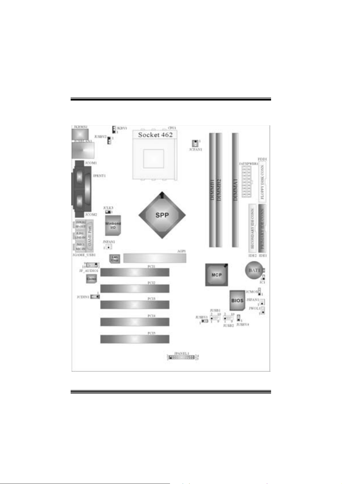
Layout of M7NCD P r o
※NOTE: ●represent s the f irst pin.
1
Page 4
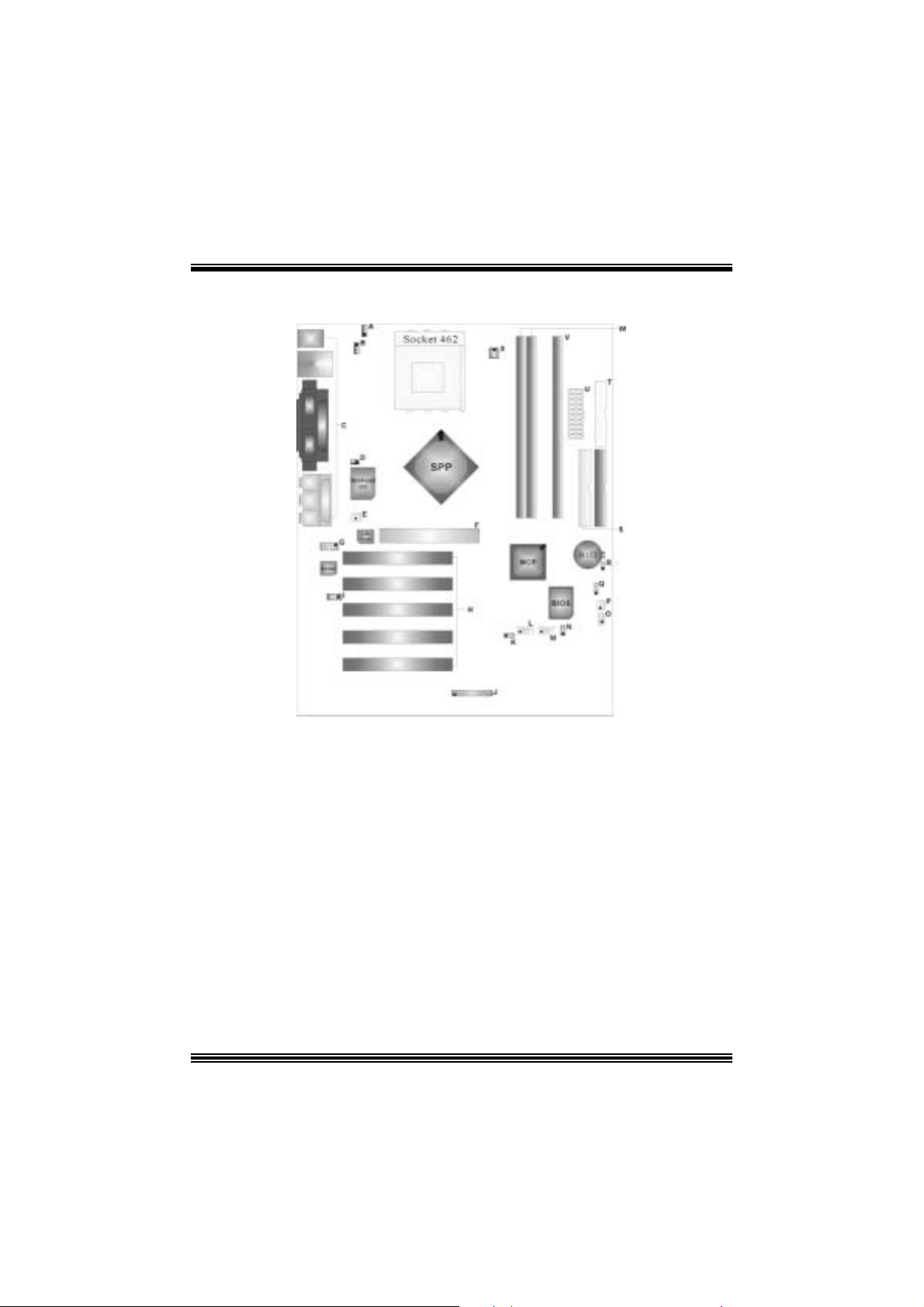
Compone nt Index
A. 5V/5VSB Selection for Keyboar d L. Front USB Header (JUSB1)
a n d mouse (JKBV1) M. Front US B Head er (JUSB2)
B. Power Sour ce Selection f or USB N. Power Source Selection for USB
(JUSBV2) (JUSBV4)
C. Back Panel Connector O. Wake On LAN Header (JW OL1)
D. Frequency Selection (JCLK3) P. System FAN Header (JSF AN1)
E. Nor th Bridge Fan Header (JNFAN1) Q. Clear CMO S F u nction ( JCMOS )
F. Accelerated Graphi cs Port Slot R. Case Open Connector (JC 1)
(AGP1) S. IDE Connectors (IDE1-2)
G. Front Audio He ader (J F_AUDIO1) T. Floppy Disk Connector (FDD1)
H. PCI BUS S lots (PCI1-5 ) U. ATX Power Connector (JATX PWER1)
I. CD-RO M Audio-In Header (JCDIN1 ) V. DIMM Modules (DIMMA1)
J. Front Panel Connector (JPANEL1) W . DIMM Modules (DI MMB1-2)
K. Power Sour ce Selection f or USB X. CPU Fan Connector (J CFAN 1)
(JUSBV1)
2
Page 5

English
M7NCD Pro Features
A. Har dware
CPU
Pr ov ide s S o cke t-462 .
Su pports the AMD® proc essor up t o XP 3200+.
F ront Side Bus at 266/333/400 MHz.
Chipset
N ort h Br idge: nFORC E2 SP P.
Sout h Bridge: nMCP.
oH igh Speed 800Mb/s Hyper-Trans port interface to the MCP.
Main Me m o ry
Support s up t o 3 DDR devices .
Support s 266/ 333/ 400MHz (wit hout ECC ) DD R dev ices.
High performanc e 128 bit DDR 400 Twin Bank Mem ory Arc hitecture.
Maxi mu m me mo ry s i ze o f 3GB.
Super I/O
Chip: Winbond W83 627H F.
Slots
F ive 32- PCI bus master slots.
One AGP: nAGP3.0 8X interfac e at 533Mb/s.
oSupports AGP 2X, 4X, 8X.
On Board IDE
Supports four IDE di s k dri ves.
Supports PIO Mode 4, Master Mode and Ult ra DMA 33/ 66/100/ 133 Bus Mast er
Mode.
On Bo ard AC’97 Sound Cod ec
Chip: ALC650.
Compliant with AC ’97 s pec ificat ion.
AC9 9 2.2/2. 3 interfac e.
Support s 6 c hannels.
On Board Periphera ls
a. R e ar si de
2 s erial port s.
1 parallel port. (SPP/EPP/ECP m ode)
Audio ports in horizontal position.
1 LAN port. (optional)
3
Page 6
PS/2 mouse and PS/2 keyboard.
2 USB2.0 ports.
b. F ront Si d e
1 floppy port supports 2 F DDs with 360K, 720K, 1.2M, 1. 44M and 2.88Mby t es.
4 USB2.0 port s.
1 front audio header.
Dimensions
ATX F orm F actor: 24.4cm X 30.4cm (W X L)
B. BIOS & S oftware
BIOS
Award legal Bios .
APM1.2.
ACPI.
USB Function.
Software
S upports C PU SaviorTM, 9t h T ouchTM, FLASHER™, WinFlasher
(optional) and Watc hdog
Offers the highest performance for Windows 98 SE, Windows 2000, W indows Me,
Windows XP, SC O UNIX etc.
TM
.
TM
, St udioF un!
TM
Package contents
HDD Ca b le X1
FDD Cable X1
User’s Manual X1
USB Cable X1 (optional)
Rear I/ O Panel for ATX Cas e X1 (optional)
Fully Setup Driver CD X1
St udioF un! Application CD X1 (optional)
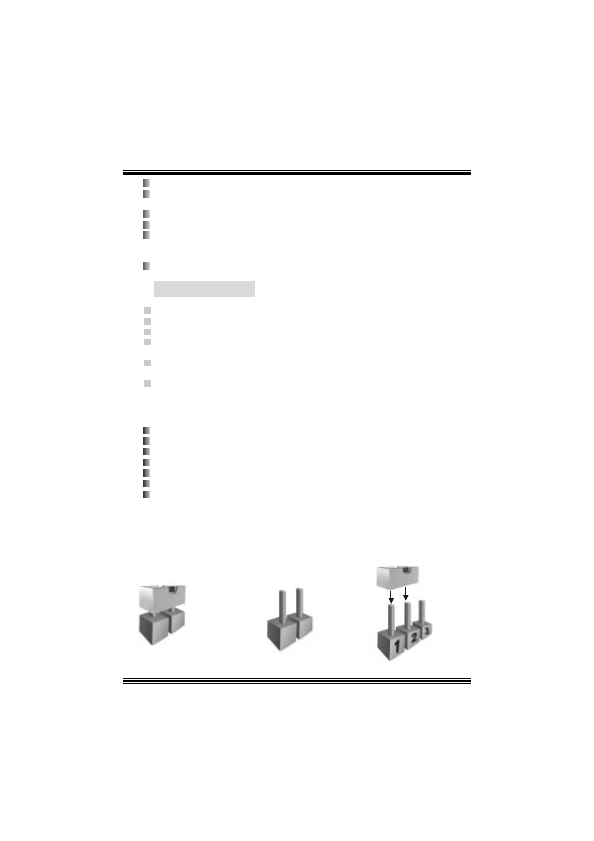
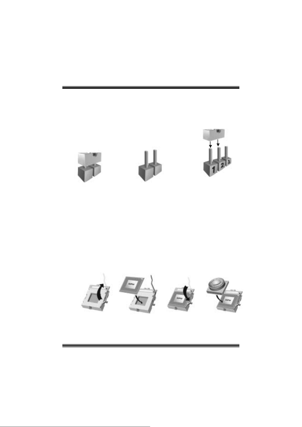
Ho w to setup Jumper
The illustrat ion sho ws how jum pe rs are s e tu p. When the Jum per c ap is placed on pins, the
jumper is “close”. If no jumper cap is placed on the pins, the jumper is ”open”. The
illust rat ion sho ws a 3-pin jumper whos e pin 1and 2 are “close” when jumper c ap is placed
on thes e 2 pins .
Jumper close Jumper open Pin1-2 close
4
Page 7
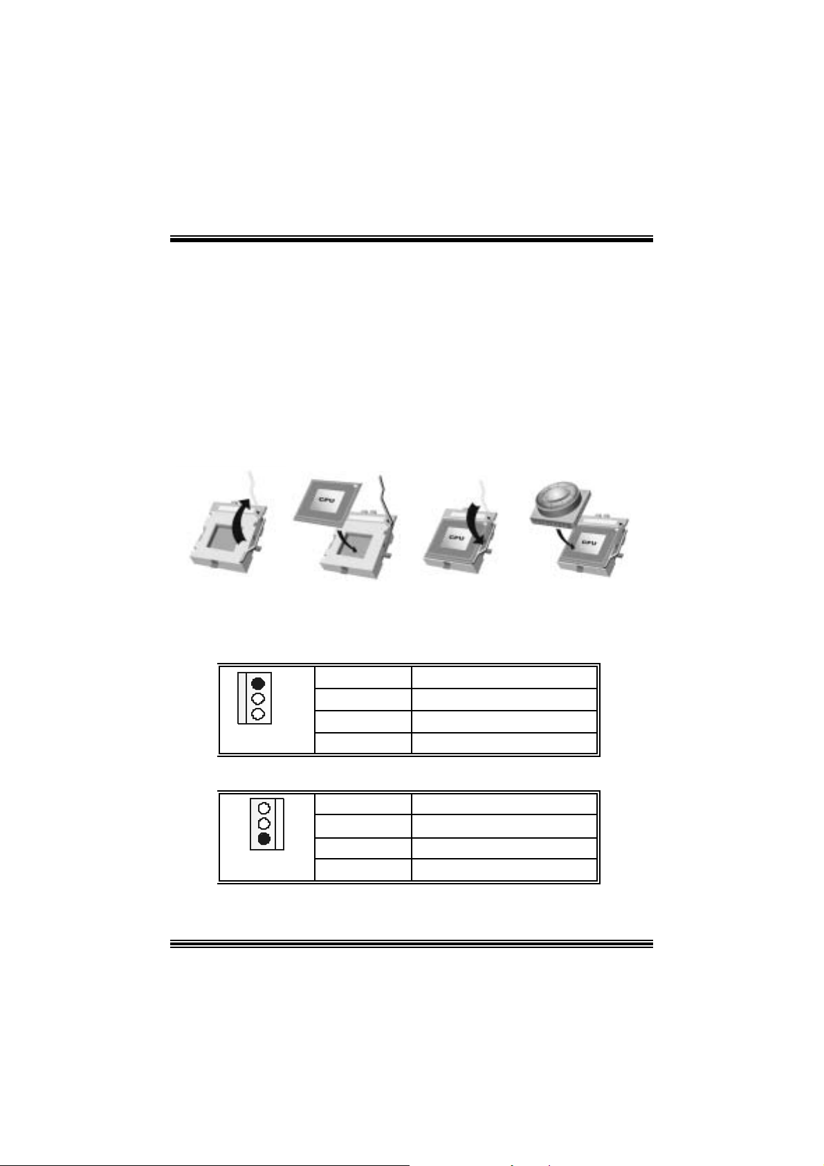
CPU Installation
Step1: Pull the lever sideway s away from the s ock et and then raise the lever up to a
90 -degree angl e.
Step2: Look for the white dot/c ut edge. The whit e dot/cut edge should point towards the
lev er pivot. The C PU will f it only in the c orrect orient ation.
Step3: Hold the CPU down fir ml y, and then close the lever.
Step4: Put t he C PU f an on t he C PU and buck le it. Connect the CPU fan power c able t o
the JCFAN1. This completes the installation.
Step1 Step2 Step3 Step4
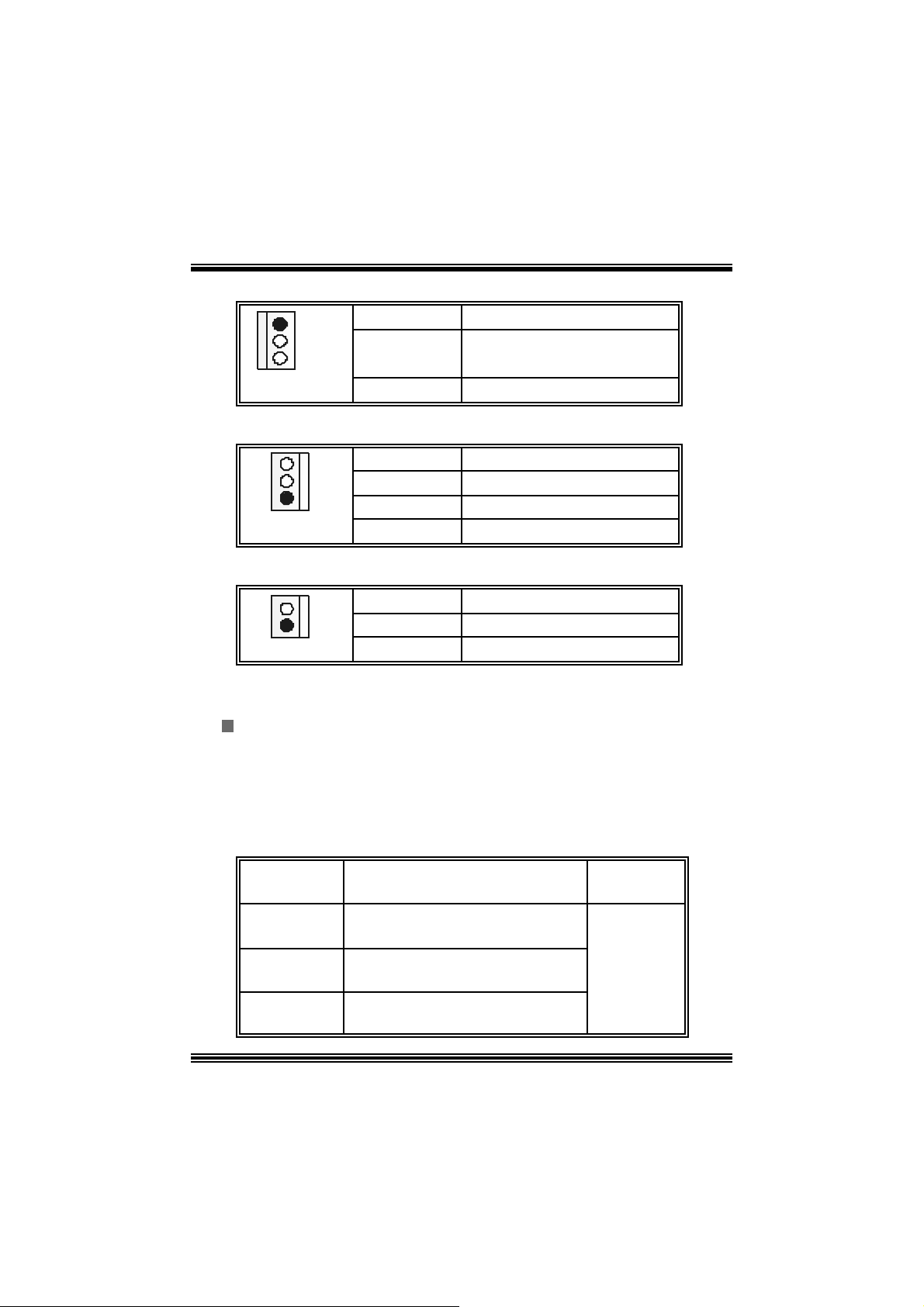
CPU Fan Header: JC FAN1
1
JCFAN1
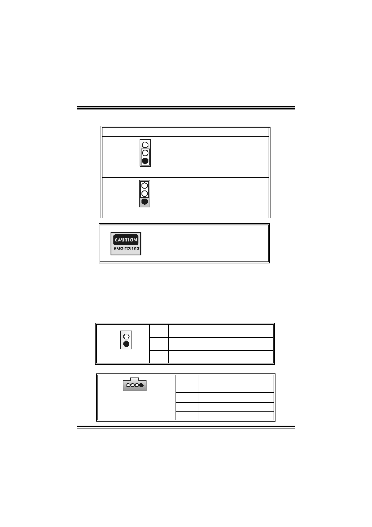
S ystem Fan Header: JSFAN1
1
JSFAN1
Pin No. A ssi gnm e nt
1 Ground
2
3
+12V
Sense
Pin No. A ssi gnm e nt
1
2
3
5
Ground
+12V
Sense
Page 8
North Bridge Fan Header: JNFAN 1
Pin No. A ssi gnm e nt
1
JNFAN1
1
2
Ground
+12V
D DR DIMM Mod ules : DIMMB 1 -2, D IMMA1
For Du al- chann el DDR (1 28-b it) hi gh perfo r m an ce , at least 2 or more
DIMM modules must be installed. (It has to be the combination of
DIMM A and DIMM B.) With only one DIMM installed, the memory
performs onl y at 64-bit.
DR AM Access Time: 2.5V Un buff ere d DDR 266/333/40 0 MHz Type re qui red.
DRAM Type: 64MB/ 128MB/ 256MB/ 512MB/ 1GB DI MM Module (184 pin)
Total Memory Size wit h Unbuffere d DI MM s
DI MM S ocket
DDR Mod u l e To tal Memory
Location
DIMMB1 64MB/128MB/256MB/512MB/1GB
DIMMB2 64MB/128MB/256MB/512MB/1GB
DIMMA1 64MB/128MB/256MB/512MB/1GB
***On ly for refer en ce***
Installing DDR Module
1. Unlock a DIMM slot by pressing the
retaining clips outward. Align a DIMM on
t he s lot s uc h t hat t he no t c h on th e D IMM
ma t ches t he break o n the sl ot .
2. Ins ert the DIMM f irmly and vertically into
the s lot until the ret ain ing c hip s nap back in
place and the Dimm is properly seat ed.
*1
*1
*1
Size (MB)
Max is
3GB
6
Page 9
Jumpers, Headers, Connectors & Slots
Floppy Disk Connector: FDD1
The mot herboard provides a standard f loppy disk connector that supports 360K,
720K, 1.2M, 1.44M and 2.88M floppy disk types. This connector supports the
prov ided f loppy drive ribbon cables .
Hard Disk Connectors: IDE1/ IDE2
The motherboard has a 32-bit Enhanced PCI IDE Controller that provides PIO
Mode 0~4, Bus Mast er, and Ultra DMA 33/ 66/ 100/ 133 functionality. It has t wo
HDD connec t ors IDE1 (primary) and IDE2 (secondary).
The ID E c onnectors can c onnect a master and a slav e driv e, so you can connect
up to four hard disk drives . The f irst hard drive s hould alway s be c onnected t o
IDE1.
Peripheral Component Interconnect Slots: PCI 1-5
This m ot herboard is equipped with 5 st andard PCI s lots. PCI stands for Peripheral
Component I nterconnec t, and it is a bus standard for expansion cards. This PCI
slot is des ignated as 32 bits.
Accelerate d Graphics Port Slot: AGP1
Your monitor will attach directly to that video card. This motherboard supports
video cards f or PC I s lots, but it is als o equipped with an Accelerated Graphics Port
(AGP). An AGP c ard will take advantage of AGP technology f or improv ed video
efficiency and perform ance, es pecially with 3D graphics.
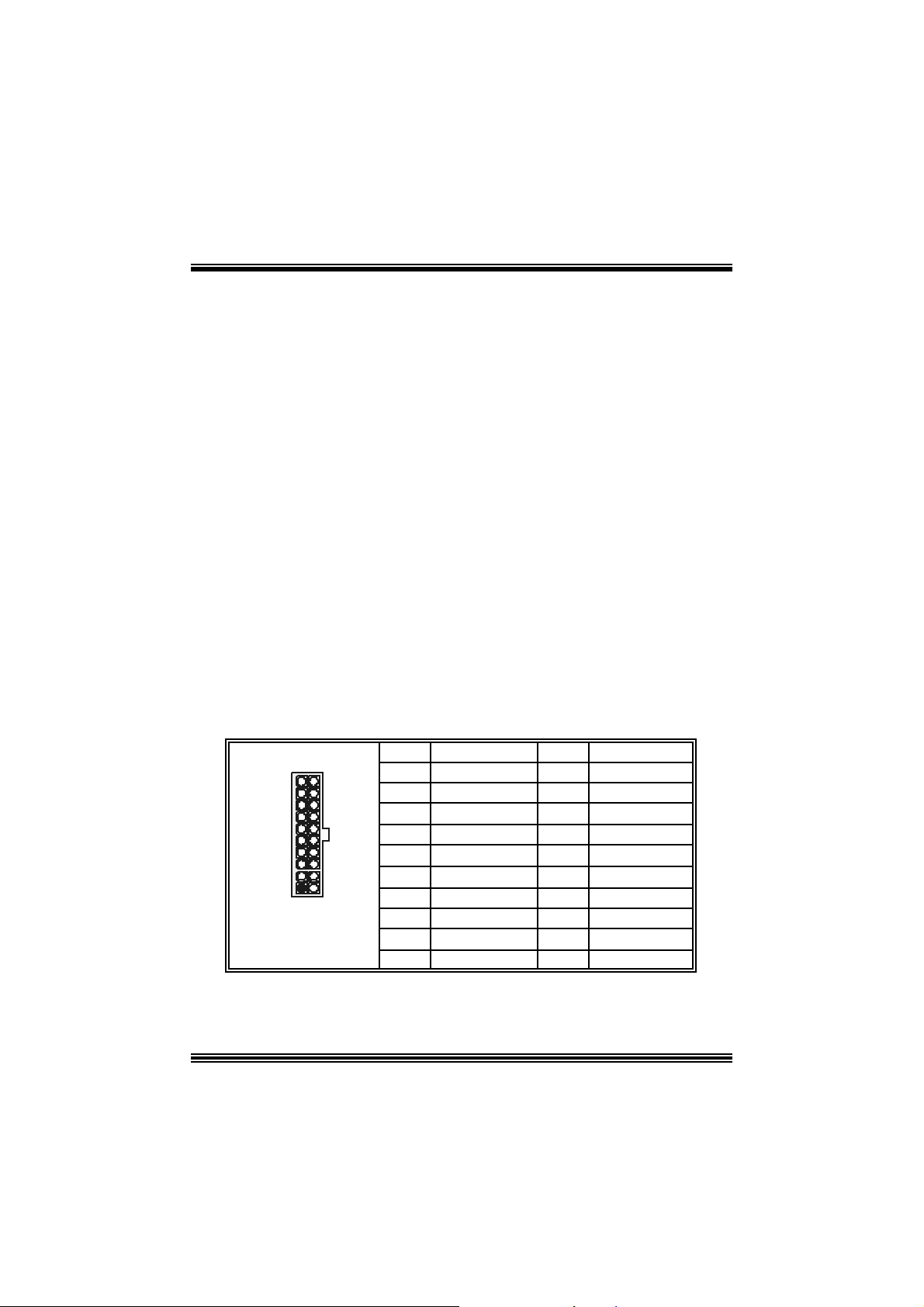
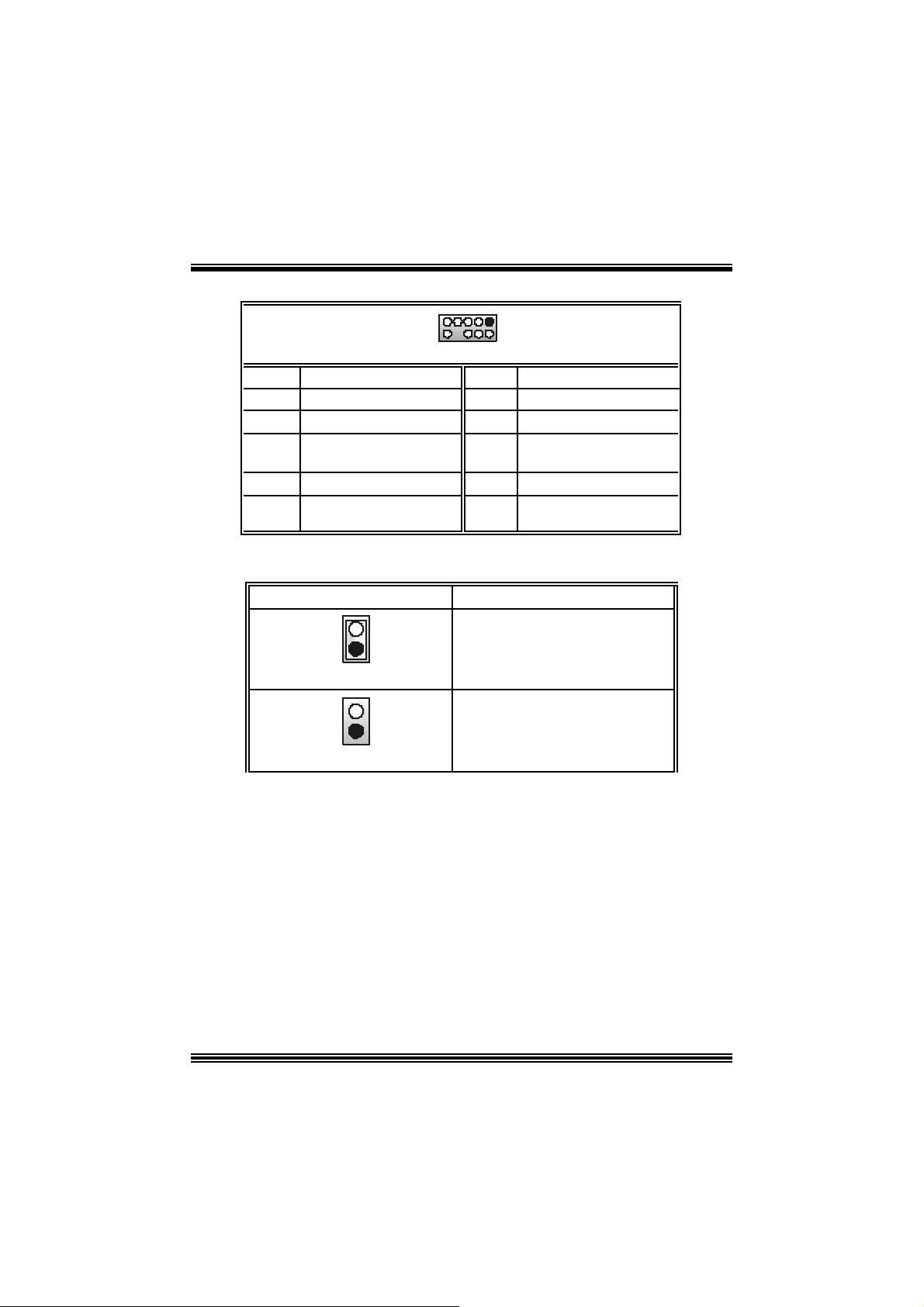
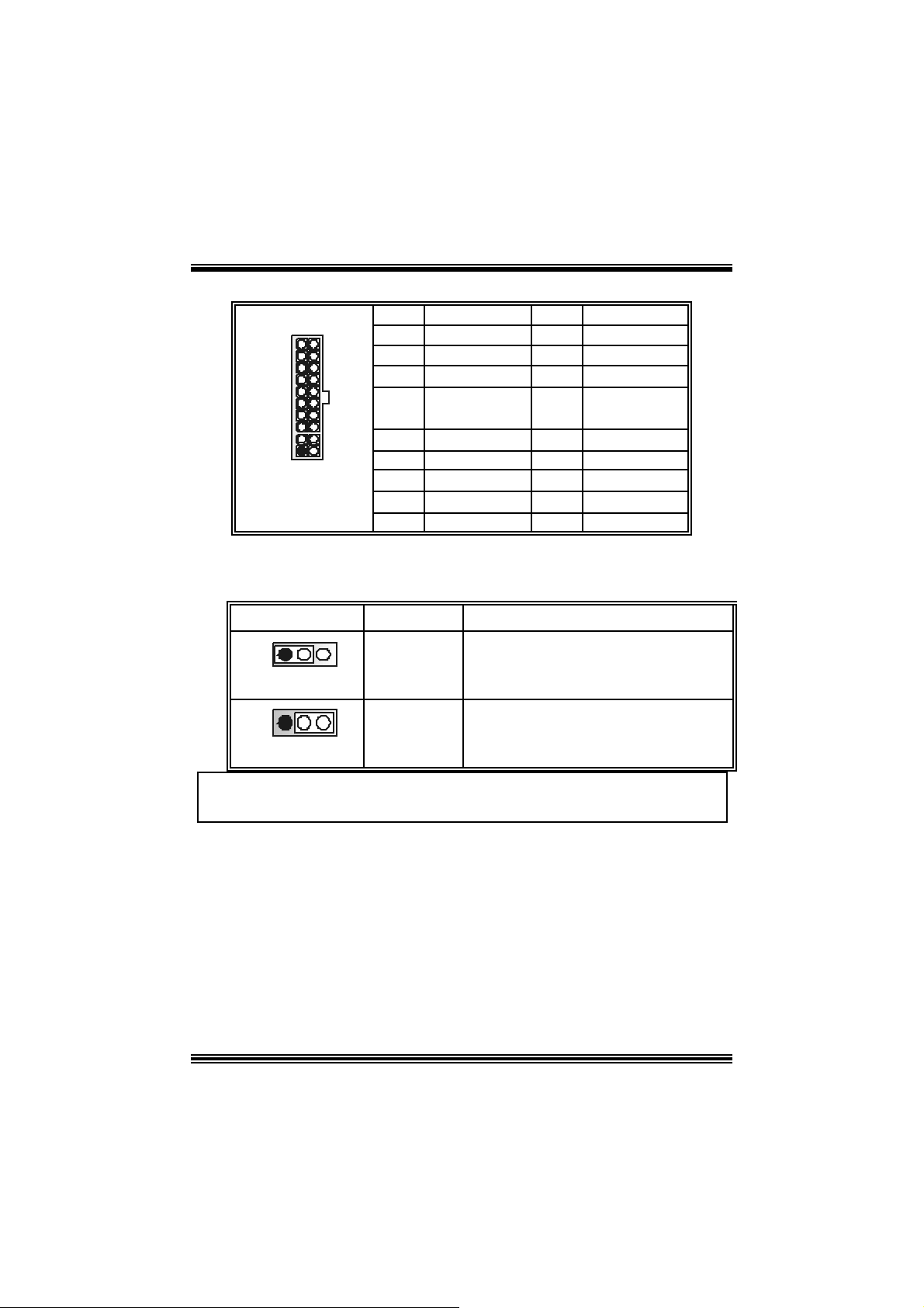
Power Conn ectors: JATXPWER1
PIN Assignment PIN Assignment
1 +3.3V 11 +3.3V
2 +3.3V 12 -12V
3 Ground 13 Ground
4 +5V 14 PS_ON
5 Ground 15 Ground
6 +5V 16 Ground
7 Ground 17 Ground
8 PW_OK 18 -5V
9 +5V_SB 19 +5V
10 +12V 20 +5V
10
1
JATXPWER1
20
11
7
Page 10
0
9
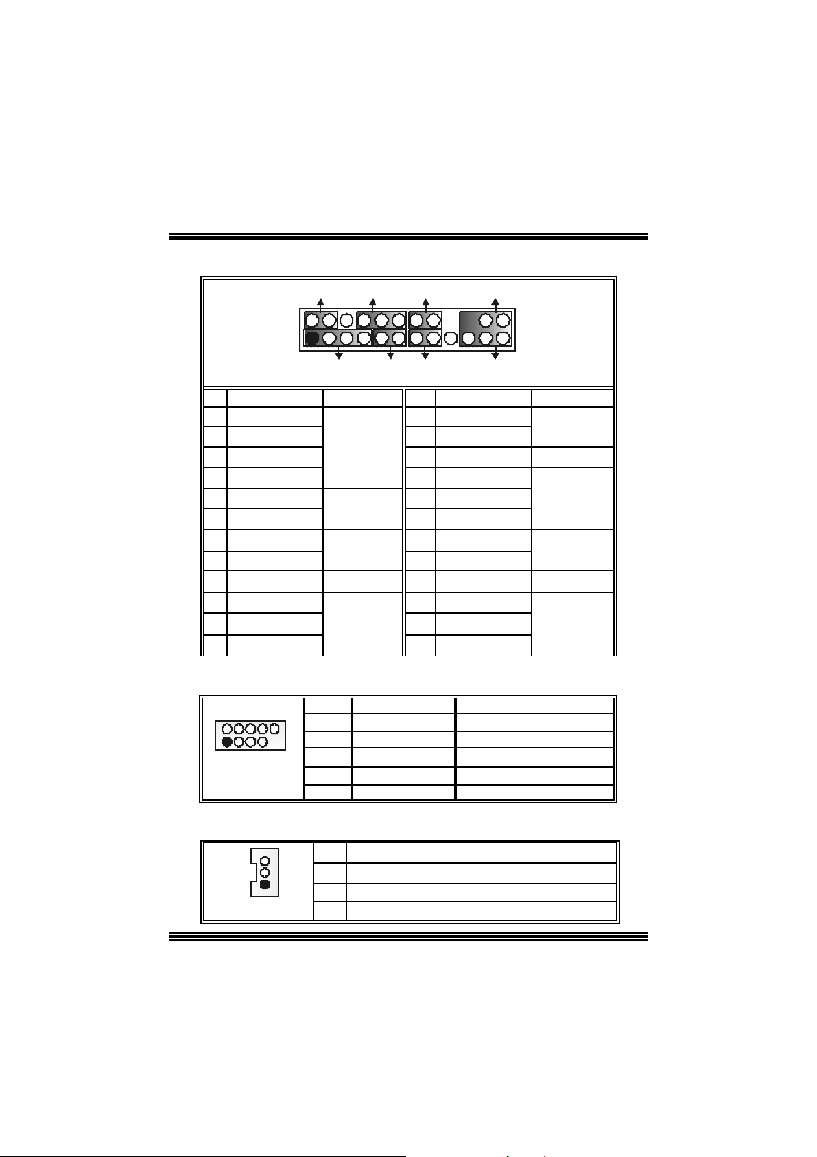
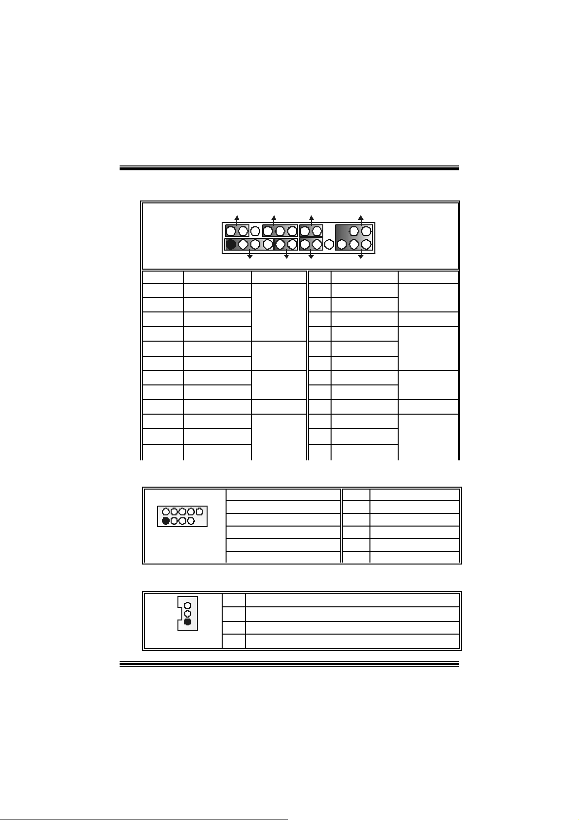
Front Pane l Conne ctor: JPANEL1
SLP
JPANEL1
Pin Assignment Function Pin Assignment Function
1 +5V 2 Sleep C ontrol
3 NA 4 Ground
5 NA 6 NA NA
7 Speaker
9 H DD L E D (+ ) 10 Power LED (+)
11 H DD LED (-)
13 Ground 14 Power Button
15 Reset Control
17 NA 18 KEY
19 NA 20 KEY
21 +5V 22 Ground
23 IRTX
2
123
PWR_LED
(+) (-)(+)
SPK
Hard Dr ive
(+) (-)
HLED
RST
Speaker
Connector
8 Power LED (+)
LED 12 Power LED (-)
Reset
Button
IrDA
Connector
16 Ground
24 IRRX
IRON/ OFF
IR
24
Sleep
Button
POWER
LED
Power-on
Button
IrDA
Connector
Front USB Header: JUSB1/2
Pin Assignment Pin Assignment
1
1
3
5
7
+5V(fused)
USBP4-
USBP4+
Ground
2
4
6
8
+5V(fused)
USBP5-
USBP5+
Ground
2
1
JUSB1/2
9 KEY 10 NA
Wake On LAN He ader: JWOL1
Pin Assignment
1
JWOL1
1 +5V_SB
2
3 Wake u p
8
Ground
Page 11
h
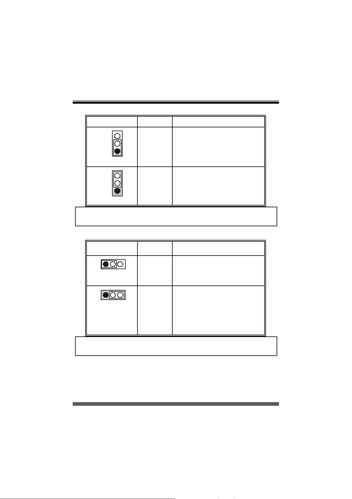
Power Source Selection for Keyboard/ Mo use: JKBV1
JKBV1 Assignment Description
3
1
Pin 1-2 c los e
3
1
Pin 2-3 c los e
+5 V
+5V Standby
Voltage
+5V for keybo ard and mouse
PS/2 Mous e and PS/2 Key board are
powered with +5V standby v oltage
Note: In order to power-on keyboard and mouse function, “JKBV1” jumper
cap should be placed on pin 2-3.
Power S our ce Selecti on fo r USB: JUSBV1/ JUS BV2/ JUSBV4
JUSBV1/JUSBV2/
JUSBV4
1 3
Pin 1-2 c los e
1 3
Pin 2-3 c los e
Assignment Description
+5V Standby
+5 V
Voltage
JUSB V1: 5V for JUSB 1 port
JU SBV2: 5V for JU SBLAN1 port
JUSB V4: 5V for JUSB2 port
JU SBV1: JUSB1 port powered with
standby v olt age of 5V
JUSBV2: JU SBLAN1 port powered wit
standby v olt age of 5V
JU SBV4: JUSB2 port powered with
standby v olt age of 5V
Note: In order to power-on USB devices function, “JUSBV1/JUSBV2/
JUSBV4” jumper cap shoul d be placed on pin 2-3 respectivel y.
9
Page 12
Clear CMOS Jumper: JCMOS
p
JCMOS Assignment
3
1
Pin 1-2 C lose
3
1
Pin 2-3 C lose
The fo llowing procedu res a re for res etting the
BIOS
assword . It is i mportant to follow these
ins truct ions c lose ly.
※ Clear CMOS Procedures:
1. R emov e AC power line.
2. Set the jumper to “Pin 2-3 C lose”.
3. Wa it for fi ve seconds.
4. Set the jumper to “Pin 1-2 C lose”.
5. Power on t he AC .
6. Reset your desired pas sword or clear th e CMOS data .
Ca se Op e n Connec tor : JC1
Norm al Operation (def ault)
Clear CMOS Data
Pin
1
JC1
1
2
Case Open Signal
CD-ROM Audio-In Heade r: JCDIN1
Pin Assignment
1
2
3
4
10
JCDIN1
1
Assign m ent
Ground
Left Channel In put
Ground
Ground
Right Channel In put
Page 13
Front Panel Audio Header: JF_AUDIO1
9
10
JF_AUDIO1
Pin Assignment Pin Assi gnment
1
3
5
7
9
Mic I n / C e nter
Mic Power/ Bass
Right Line Out/ Speaker
Ou t Ri ght
Reserved
Left Line Out/ Speaker
Out Left
1
2
2
4
Right Line Out/ Speaker
6
8
10
Ground
Audio Power
Ou t Ri ght
Left Line Out/ Speaker
Out Left
Key
System Ope ration Mode: JCLK3
Note: W hen ov erclock function failed and system is unable to boot-up, please
follow the instructio n below:
1. Tu r n off th e system.
2 . Closed the JCLK3 jumper .
3. Turn on the sys t em.
4. Enter CMOS s et up menu and load def ault s sett ings .
5. Tu r n off th e system.
6. Open t he JCLK3 jum per.
7. Turn on the sys t em.
JCLK3 Assignment
1
Pin 1-2 Clos e
1
Pin 1-2 Open
User Mode (def ault )
(133/ 166 MHz)
Safe mode
(100 MHz)
11
Page 14
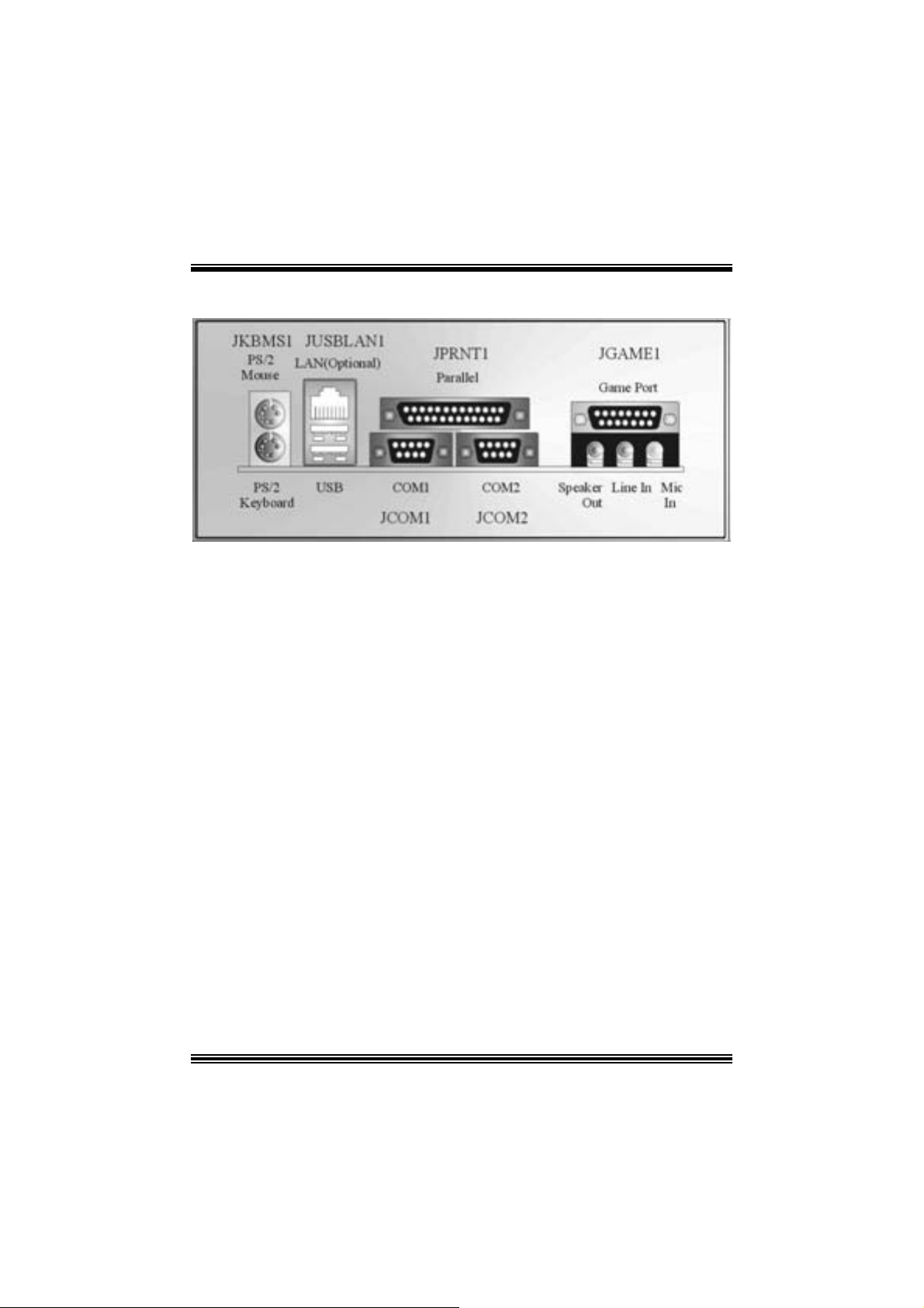
B ack Panel Connectors
12
Page 15

Deutsch
Spezifikatione n von M7 NCD Pro
A. Har dware
CPU
Unterstützung für Sockel 462.
Unterstützung für den AMD® Prozessor bis zu XP 3200+.
F SB mit 266/ 333/ 400 MHz.
Chipsatz
N orthbridge: nF ORCE2 SPP.
Sout hbridge: MCP.
Hauptspeicher
Unter stützung fü r 3 DDR Ge räte.
Unterstützung für 266/333/ 400MHz (ohne ECC) DDR Gerät e.
128-Bit H igh-Performance DDR400 mit der Twin-Bank Archit ektur.
D ie m ax imale Speichergröße ist 3GB.
Super I/O
Chip: Winbond W83 627H F.
Slots
F ünf 32-Bit PCI -Bus-Slots .
Ein AGP-Slot: n AGP3.0 8X Int erfac e bei 533Mb/ s.
o U nterstüt zung f ür AGP2.0 2X, 4X und 8X.
Onboard-IDE
Unterstützung fü r vi er IDE Diskettenl au fwe rke.
U nterstüt zung für PIO Modus 4, Mas t er Modus und Ultra DMA 33/66/100/133 Bus
Mast e r Mo dus .
On-board AC’97 Sound Codec
Chip: ALC650.
Ent s pricht die Spezifikation von AC ’97.
AC 99 2. 2/2. 3 I nterfac e.
Unterstützung für 6-Kanal.
Onboard-Peripheriegeräte
a. R ü c kwan d
2 Se riell-Ports.
1 parallele Sc hnittstelle. (SPP/EPP/ECP-Modus )
1 horizontales Audio-Port.
1 LAN -Port. (opt ional)
Unterstützung für PS/2-Maus und PS/2-Tast at ur.
13
Page 16

2 USB2.0-Ports.
b. Vorder seit e
1 F loppy-Port m it Unterstützung f ür 2 Dis k et t enlauf werke.(360KB, 720KB, 1.2MB,
1.44MB und 2.88MB)
4 USB2.0-Ports.
1 Audio-Header für die Vondersei te
Abmessungen
ATX F orm -Fac tor: 24.4 X 30.4c m (W X L)
B. BIOS & S oftware
BIOS
Award legal Bios .
APM1.2.
ACPI.
USB Funktion.
Software
Unterstützung für CPU Savio rTM, 9th Touc hTM, FLASHE R™, Win FlasherTM,
StudioFun!
Unter stützung für die am mei s ten verbreiteten Be triebsyste me wie Wi ndows 98SE,
Windows 2000, W indows ME, Windows XP and SC O UNIX usw.
TM
(optional) and WatchdogTM.
Verpack ungsinhalt
HDD K a b le X1
FDD Kable X1
Benut zer Handbuch X1
USB Kable X1 (optional)
I/O-Rückwand f ür ATX Gehäuse X1 (optional)
Treiber C D für Installation X 1
St udioF un! Anwendung CD X1 (optional)
14
Page 17
Ei nst e l lu ng de r Jum per
Die Abbildung verdeutlicht, wie Jumper eingestellt werden. Pins werden durch die
Jum per-Kappe v erdeckt, ist der Jum per ”geschlossen”. Keine Pins werden durch die
Jum per-Kappe verdeckt, is t der Jum per “geöffnet”. Die Abbiildung zeigt einen 3-Pin
Jumper dessen Pin1 und Pin2 ”geschlossen“ sind, bzw. es befindet sich eine
Jum per-Kappe auf dies en beiden Pins.
Jumper geschlossen Jumper geöffnet Pin1-2 geschlossen
In stallat ion der CPU
Sc hritt 1 : Z iehen Sie den H ebel s eitlich vom Sockel weg. Heben Sie den Hebel dann
in 90-Grad-Winkel nac h oben.
Sc hritt 2 : Suchen Sie nac h der scharfen Kant e, die auf D rehpunkt des Hebels
weisen m uss . Die CPU passt nur, wenn s ie ric htig aus geric ht et ist.
Sc hritt 3 : D rück en Sie die CPU f est in den Sock el und s c hließ en Sie den Hebel.
Sc hritt 4 : Ste cken Sie Ih ren CPU-Lüf ter auf die CPU. Schließen Sie die Stromversorgung sstecker
für CPU -Lüft er an JCFAN1 an. D ann beenden Sie die Installat ion.
Schritt 1 Schritt 2 Schritt 3 Schritt 4
15
Page 18
CPU- Lüfter Headers: JCFAN1
1
Pin
1
JCFAN1
2
3
Belegung
Masse
+12V
Sensor
System-Lüfter Headers: JSFAN 1
Pin
1
1
JSFAN1
2
3
Belegung
Masse
+12V
Sensor
Northbridge-Lüfter Header: JNFAN1
Pin
1
JNFAN1
2
1
Belegung
Masse
+12V
DDR- DI MM- Module s: DIMMB1-2, DIMMA1
Für D ual -Kana l DDR (128 -Bi t) Hi gh-Per fo rmance, muss man mindeste ns
2 oder m e hr DIMM-Modul e ins ta l lie r e n. (Es ist unbe din gt, daß m an DIMMA
mit DIMMB als ein Paar benutzt.) Wenn man nur ein DIMM installiert,
funktioniert der Spreicher nur 64-Bit.
DRAM-Zugriffszeit: 2.5V nicht registrierter DDR 266/333/400 MHz Typ
erforderlich.
DR AM Ty pen: 64MB/ 128MB/ 256MB/ 512MB/ 1GB D IMM-Module (184-Pin)
Gesa m t Spei che rgröße v on ni cht reg is trierte r DIMM s
DIMM-Sockel
Standort
DIMMB1 64MB/128MB/256MB/512MB/1GB
DIMMB2 64MB/128MB/256MB/512MB/1GB
DIMMA1 64MB/128MB/256MB/512MB/1GB
DDR-Modul Speichergröße
*1
*1
*1
**Nur als Refer enz***
16
maxi mal
3GB
Page 19

Installation von DDR-Modul
1. Öffnen Sie einen DIMM-Slots, indem Sie
die seitlich Chips nach außen drücken.
Ric ht en Sie das D I MM-Modul so über dem
Slot aus, dass das Modul mit der Kerbe in
den Slot passt.
2. Drüc ken Sie das DIMM-Modul in den Slot,
bis die seitlic hen Clips zuschnappen und
das Modul fest sitzt.
Jumpers, Headers, Anschlüsse & Slots
Diskettenanschluss: FDD1
Das Motherboard enthält einen st andardmäßigen Diskettenans chluss, der 360K-,
720K-, 1.2M-, 1.44M- und 2.88M-Disketten unterstützt. Dieser Anschluss
unt ers tützt die mit gelief erte Bandkabel des Diskettenlauf werks.
Fe stplatt enanschlüsse: IDE1 und ID E2
Das Mainboard hat einen 32-Bit Enhanced PCI IDE-Controller, der die Modi
PIO0~4, Bus Mast er sowie die U ltra DMA/33/ 66/100/133- Funkt ion zur Verfügung
stellt. Dieser ist mit zweii HDD-Anschlüssen versehen IDE1 (primär) und IDE2
(sekundär).
Die ID E-Anschlüsse k önnen eine Master- und eine Slav e-Festplatte v erbinden, so
dass bis zu 4 Festplatten angeschlossen werden können. Die erste Festplatte
sollte im m er an IDE1 angeschlossen werden.
Periphera l Component Int erconnect Slots: P CI1-5
Dieses Motherboard ist m it 5 standardmäß igen PCI-Slots ausgestattet. PC I steht
für Peripheral Component Interc onnect und bezieht sich auf einem Busst andard für
Erweiterungskarten, der den älteren ISA-Busstandard in den meisten
Schnittst ellen ers etzt hat. Dieser PCI-Slot ist f ür 32 bits v orgesehen.
Accelerate d Graphics Port Slot: AGP1
Ihr Monitor wird direkt an die Grafikkarte angeschlossen. Dieses Motherboard
unterstützt Grafikkarten f ür PCI-Slots, aber es ist auch mit einem Accelerated
Graphic s Port ausges tattet. AGP-Karten v erwenden die AGP-Technologie, um die
Wirks amk eit und Leistung v on Videosignalen zu v erbessern, besonders wenn es
sich um 3D-Graf iken handelt.
17
Page 20
Anschlüsse für die Vo rderseite: J PANEL1
SLP
JPANEL1
Pin Belegung Funktion Pin Belegung Funktion
1 +5V 2 Sleep Cont rol
3 Kein 4 Masse
5 Kein 6 Kein Kein
7 Lautsprecher
9 HDD LED (+) 10 P ower L ED ( +)
11 HDD LED (-)
13 Masse 14 Power-Knopf
15 Reset Control
17 Kein 18 Schlüsse Kein Pin
19 Kein 20 Schlüsse
21 +5V 22 Masse
23 IRTX
2
1
PWR_LED
(+) (-)(+)
SPK
(+) (-)
HLED
Lautsprecher
Anschluss
Festplatte
LED
Zurücksetzn-
Knopf
IrDA-
Anschluss
IRON/ OFF
24
23
RST
8 P ow er L ED ( +)
12 Power LE D (-)
16 Masse
24 IRRX
IR
Schlafen-
Knopf
Power-
LED
Power-On
Knopf
IrDA
Anschluss
Front USB Header: JUSB1/2
2
1
JUSB1/2
10
9
Pin
1
3
5
7
9
Belegung
+5V(geschmelzt)
USBP4-
USBP4+
Masse
Schlüsse
Pin
2
4
6
8
10
Belegung
+5V(geschmelzt)
USBP5-
USBP5+
Masse
Kein
Wake On LAN He ader: JWOL1
1
JWOL1
Pin
1 +5V_S B
2
3 Wake-up
18
Belegung
Masse
Page 21
Stromversorgungsanschluss: JATXP WER1
10
20
1
11
JATXPWR1
PIN Belegung PIN Belegung
1 +3.3V 11 +3.3V
2 +3.3V 12 -12V
3 Masse 13 Masse
4 +5V 14 PS_ON
5 Masse 15 Masse
6 +5V 16 Masse
7 Masse 17 Masse
8 PW_OK 18 -5V
9 +5V_SB 19 +5V
10 +12V 20 +5V
Auswahl von Stromversorgungsmodi für Tastatur/ Maus:
JKBV1
JKBV1 Beschreibung Funktion
1 3
Pin 1-2
geschlossen
1 3
Pin 2-3
geschlossen
+5 V
+ 5V r eserv i ert e
Spannung
PS/2-Maus und PS/2-Tast at ur werden durch
5V für Tas tatur und Maus
5V res erviert e Spannung akt iviert
Anmerkung: Um die “power-on by Keyboard and Mouse“ Funktion zu
behandel n, sollen Pin2-3 durch die Jumperkappe verdeckt werden.
19
Page 22

Auswahl von Stromsversorgungsmodi für USB: JUSB V1/
JUS BV2/JUSBV4
JUSBV1/JUSBV2/
JUSBV4
1 3
Pin 1-2 geschlossen
1 3
Pin 2-3 geschlossen
Beschreibung Funktion
+5 V
+5V_SB JU SBV1: JUSB1 ist a ktiviert durch
JUSBV1 : 5V für JUSB1
JUSBV2: 5V für JUS BLAN1
JU SBV4: 5V für JU SB2
die reservierte 5V Spannang
JUSBV2: JU SBLAN1 ist ak t iviert
durc h die reservierte 5V Spannang
JU SBV4: JUSB2 ist akt iviert durch die
res ervierte 5V Spannang
Anmerkung: Um die “power-on by USB-Geräte” Funktion zu behandeln,
sollen pi n2-3 vo n JU BV1/ JUBV2/ JU SBV4 durch di e.
Jumper zum Löschen CMOS: JCMOS
JCMOS
3
1
Pin 1-2 gesc hlossen
3
1
Pin 2-3 gesc hlossen
Die folgend e Schritte leiten Si e, das Kennwort für
BIOS -System zurückzusetzen. Es ist wichtig, die
Anweisung zu folgen.
Beschreibu ng
Normale Operation (D ef ault)
CMO S-Daten Lös c hen
20
Page 23

※ Prozeß zum Löschen des CMOS:
1. Aussc halten Sie den AC-Netzstec k er.
2. Lassen Sie Pin 2-3 von JC OMS1 ges hclossen sein.
3. Bitte wart en Sie 15 Sekunden.
4. Lassen Sie Pin 1-2 von JC OMS1 ges hclossen sein.
5. Schließ en Sie den AC-Netzsteck er an.
6. Z urüc kset zen Sie das Kennwort nach ihrem Wille oder lös c hen
Sie die C MOS-D aten.
Anschluss für Gehäuse-Ö ffnen: JC1
Pin
1
JC1
1
2
Belegung
Gehäus e Öffnen Signal
Masse
CD-ROM Audio-In Heade r: JCDIN1
1
JCDIN1
Pin Belegung
1
2
3
4
Link-Kanal Eingabe
Masse
Masse
Rec ht -Kanal Eingabe
Front Panel Audio Header: JF_AUDIO1
9
10
JF_AUDIO1
Pin Belegung Pin Belegung
1
3
5
7
9
*R es erviert: N icht in Gebrauc h
Mikrofon-Eingang
Mikrofon-Betriebsspannung
Recht Line-Out
Reserv iert
Link Line-Out
2
4
6
8
10
1
2
Audio-Spannung
Recht Line-Out
Schlüsse
Link Line-Out
Masse
21
Page 24

System Ope ration Modus: JCLK3
Anmerkung: Wenn “Überspanng Funkt ion” nicht gelungen ist folgen Sie bitt e
die I nstruktion darunter:
1. Bitt e vausschalton Sie den AC-N otzsteck er.
2. Lassen Sie Pin 1-2 v on JC LK3 geschloss en sein.
3. Schließen Sie den AC-Notzstecker an.
4. Betreten Sie “CMOS Setup Menü” und wählen s ie D efault-Set t ing.
5. Ausschalten Sie den AC -N etzstec k er wieder.
6. Lassen Sie Pin 1-2 v on JC LK3 geöffnet s ein.
7. Schließen Sie den AC-Netzstecker wieder.
JCLK3 Assignment
1
Pin 1-2 Geöffnet
1
Pin 1-2 Gesc hlossen
Benut zer Modus (default)
(133/ 166 MHz)
Sic herheit Modus
(100 MHz)
Anschlüsse für die Rückwand
22
Page 25

Watc hdog Technology
It is im portant to know that when overclock ing, the syst em c an b e a t a v ul nerable s tate .
Theref ore, t he BIOSTAR Watc hdog Technology was designed t o prot ect your PC under
dangerous over-clock s ituations. Any ov er-clock ing that reaches the threshold settings,
the W atchdog Tec hnology will disable y our system from rebooting in the BIOS s etting.
Under this circumstanc e, pleas e power of f your PC. After that, pres s <Ins ert> and power
on y our system simultaneous ly to restart your system. This user-f riendly design can
sav e you f rom s quandering your t ime on opening the case just to c lear the C MOS. I n the
end, t hanks to the Watchdog Technology, everyt hing is back at a safe and sound!
23
Page 26

StudioFun!
Introduction
StudioF un! is a media-player based on optimized GNU/ Linux distribution. It play s D VD,
VCD , MP3, Audio CD and various other k nown file f ormats. You can tak e s naps hots of
video and customize the saved images as screens avers. Y ou can also store the images
on USB mass storage dev ic es like flash disks and USB floppy disks.
Hardware Requirements
The supported hardware list of StudioFun! grows up every day. So please check the
hwreq.txt located in the root of StudioFun! Installation CD to get the most updated
information.
Ins tallatio n Proce dure
Ins ert the StudioFun! Installation CD in a CD/DVD ROM drive and let the system boot
through the CD. The dis k will boot and bring up the grub boot loader installation menu.
Two opt ions are specif ied.
24
Page 27

Installation
This option will do the basic installation of the distribution. The installation works on
pre-inst alled windows or GNU / Linux dist ribution.
On select ing the ’installat ion’ option the inst aller boots and display s a dialog box indicat ing
the s pace required and waits f or a confirmation. Selecting O k will continue t he inst allat ion
while select ing Canc el will t erm inate t he installation and reboot the mac hine.
If Windows or GNU/Linux is the only OS installed on the hard disk wit h no f ree space, it
will resize the partit ion, eit her NTFS or FAT32 or ex t 2, and install StudioFun!. I n c as e the
hard dis k has a 128MB of free s p ace av ailable, t he installatio n will us e the f ree spac e.
Aft er installing the base system y ou will be prompt ed to select the res olution f rom the
following choice s
1. 1024x768 (rec om m ended)
2. 800x 600
3. 640x 480
Select the desired res olut ion. The default is 1024x768 for high-end graphic s.
Nex t y ou will be prompted t o c hoose t he DVD area/region s elec tion code. Choose t his
bas ed on the ty p e of D VDs y ou will be playin g.
The installation procedure will then probe for the type of mouse installed. The distribution
currently supports PS/2, USB and Serial mice. In case of serial m ouse you will hav e to
mov e the mouse when prompt ed. The ot her two are probed and inst alled automatic ally.
The installation procedure will now finish, the CD is eje c ted and a dialog box prompting to
reboot t he m achine is dis play ed. Pres s OK butt on and enjoy StudioFun!.
3.1.1 Error Messages
1. Media c orrupted!! Pleas e check the media! The CD -RO M is corrupt ed.
2. Extract ion of base sy s tem failed!! Pleas e try again later!! The C D -ROM is corrupted.
3. Unsupported hardware found, Aborting... If you try to install StudioFun! on an
unsupported and undocumented hardware the abov e error m ess age is popped.
4. N o device found! This error message is given if t here is no hard disk in the sy stem.
25
Page 28

Recovery
In c ase of a MBR c orruption, this option should be us ed. It will aut omatically probe the
hard disk m aster boot record and f ind out the inst alled operat ing system(s ). On succ ess it
will re-inst all the boot loader with correct options in the MBR. Any c ustom boot loader
option specified from other GNU/Linux installations will get over written by the newly
probed one.
B o oting to S t udioF un!
After Installation is ov er, rem ove the CD f rom the CD-ROM and restart the machine. After
the machine reboots, you will get the GRUB boot loader menu screen. Select the
StudioF un opt ion to boot to the St udioFun! partition.
26
Page 29

After comple te bo ot up, you get to th e main Des ktop scr een. Th e following section is
a com plete descript ion of the Desktop applicat ion.
Desktop
This is t he m ain shell of t he StudioFun s of t ware. It basic ally com prises of two cat egories ,
one is the main "media control" part and t he other is the "control panel".
Media control
The media c ontrol part of t he D eskt op has the following cont rols:
1. VCD
This c ontrol will glo w whenev e r a VCD is d etected in a DVD/CD-R OM drive. The VCD will
be auto-play ed only when it is put in to the drive when the Desktop (StudioF un! shell) is up
and running, otherwise, the control will simply glow to inform the user about a VCD
27
Page 30

present in t he DVD/CD-ROM driv e.
2. DVD
This control will glow whenever a DVD is detected in a DVD drive. The DVD will be
auto-played only when it is put in to the driv e when the D esk top (St udioFun! shell) is up
and running, otherwise, the control will simply glow to inform the user about a DVD
present in t he DVD/CD-ROM.
3. MP3
This c ontrol will glo w whenev e r a MP3 is detected in a DVD/CD-R OM drive. The MP3 will
be auto-play ed only when it is put in to the drive when the Desktop (StudioF un! shell) is up
and running, otherwise, the control will simply glow to inform the user about a MP3
present in t he DVD/CD-ROM driv e.
4. AU DIO
This control will glow whenever a AUDI O is detec ted in a D VD/CD -ROM driv e. The AUDI O
will be auto-play ed only when it is put in t o t he driv e w hen the Desktop (StudioFun! shell)
is up and running, otherwise, the control will simpl y glo w to inf orm the user about a AUDI O
present in t he DVD/CD-ROM driv e.
5. FILE
This co ntrol will glow whenever a File C D (CDs with other media type files) is det ect ed in a
DVD/CD-ROM drive. The File CD will be auto-play ed only when it is put in to the driv e
when the D esktop (StudioFun! shell) is up and running, otherwise, the control will simply
glow to inform the user about a F ile CD present in t he D VD/CD -R OM driv e.
6. EJECT MEDIA
This cont rol when c lick ed will ejec t any MP3 or File CDs f rom any of the DVD/C DR OM
driv es. In case there were no MP3 or File CDs it will eject the def ault medium, (i.e.), the
CD -ROM driv e in c ase if the user has both D VD/ CD-ROM driv e or else it will eject the
default DVD /CD-ROM drive .
7. EXIT
This is the "Power on/ off" control of the D esktop (StudioFun! shell).
Control P anel
Cont rol panel part has five icons, which are shortcuts t o other applic at ions pres ent in t he
StudioFun sof tware. Tool tips are provided on t he icons when the m ous e is rolled over
them.
28
Page 31

1. Select Region
Clicking t his icon will inv oke the applicat ion for selection DVD region settings . R ef er t o
sec t ion 5. 2 Select DVD Region application for more details.
2. Screensaver
Clicking this icon will invoke the screensav er application. Refer to section 5.3
Screensaver for more details.
3. Display Settings
Clicking this ic on will inv oke t he applicat ion for c hanging the screen resolutions. Ref er t o
se cti on 5.4, D i sp l a y Se ttin g s f or more det ails.
4. File Manager
Clicking thi s icon will invoke the file manager. Re fer to section 5 .6 File manager fo r mo r e
details .
Wh en u ser h as a DVD and a CD -ROM Drive:
If user has bot h DVD and a CD -R OM drive, DVD driv e will be giv en t he pref erence when
both the drives hold valid media in them , i.e., if the CD -ROM driv e has a media and a DVD
drive also has a media, and the StudioFun! is start ed, then the media inside t he DVD drive
will be play ed.
If in c ase the media in CD-R OM takes a longer tim e to get recognized than t he media
insid e t he D VD drive, th e media in the CD -R OM will be play e d, onc e if it is reco gnized.
Other general user scenarios
When a user clicks o n a ny of th e m edi a -c o n t rols when it is not glowing, exc ept eject m edia
and exit, the media-player will just com e up and wait f or user input .
NO DUPLIC ATE INSTANCE OF ANY APPLIC ATION WILL BE ALLOWED TO
RUN.
29
Page 32

S oftware Details
XIN E
XI N E is a m ultimedia player. I t plays bac k Audio CD, DVD, and VCD. It also decodes
mult imedia files like AVI, MOV, WMV, and MP3 from loc al dis k drives . I t interprets many of
the m ost common multimedia form ats available - and som e of the unc omm on formats,
too.
• Features of Xi ne
a. Skinnable GUI
b. Navigation controls (seeking, pause, fast, slow, next
chapter, etc)
c. On Screen Display (OSD) feat ures
d. DVD and external subtitles
e. DVD/VCD menus (requires ext ernal plugin)
f. A udio and subtitle channel selection
g. Cl osed Caption su ppo r t
h. Brightness, contrast, audio volume, hue, sat uration
adjusting requires hardw are/driver support)
i. Playlists
j. Image snapshot
k. Audio resampling
l. Soft ware de-interlacing algorithms
m. Configuration dialog
n. Aspect ratio chang ing
o. Fullscreen disp la y
• Supported File formats
a. Video CD
b. M P EG program streams (.mpg, .mpeg)
c. o gg (.og g) avi (.avi)
d. asf (.asf, .wmv)
e. QuickTime (.mov )
30
Page 33

f. MPEG-Video (.mpv, .m2v)
g. MPEG-Audio (.mp2, .mp3)
h. WAV (.wav) V ideo Codecs
i. MPEG 1/2
j. MPEG 4 (aka OpenDivX)
k. MS MP EG 4
a. C hapter 5: Software Details 10
l. Windows Media Video 7
m. Motion JPEG
• Remote Cont rol sup p ort.
a. Infrared interface
b. User-friendly
• Usage of S tudioFun! with CelomaChrome skin
a. Select VCD button to play a VCD disc
b. Select DVD button to play a DVD disc
c. Select CDDA button to p lay a Audio cd
d. Select next chapter or MRL (>>|) button to play next track
in Audio CD, VCD and MP3 songs and to play next
chapter in DVD
e. Select p revio us chapter or MRL (|< <) button to play
previous t rack in Audio CD, VCD and MP3 songs and to
play previous chapter in D VD
f. Sel ect slow mot ion (<<) butt on to play t he video / audio in
slow motion (Select play b utton after reaching t he required
position)
g. Select fast motion (>>) button to play the video / audio in
fast mot ion ( Select play button after reaching the required
position)
h. Select subs + / - button to select the approp riate subtitle
(Usable while pla ying
i. Select audio + / - button to select the appropriate audio
track (For example when
j. The DVD contains one audio track in English and the
other wit h some ot her language,
k. Usable while playing DVD’ s)
31
Page 34

l. j. Select hide button to hide the control p anel of the player
m. k. Select menu button to use menu’s while p lay ing DVD
n. l. Select co ntrol button t o ad just brightness / color
o. Select setup butt on to modify the s ettings of the play er
p. Select f.scr button t o show the video output of the play er in
q. Select snap butt on to take a snapshot of the currently
r. Sel ect plist button to add / remove / mana ge playlist
s. Select mrl button to add new file to play
Error Messa ges
full screen mode
playing video
The following error message is given if an unknown
file format is selected through Xine MRL browser
and played.
While playing mp3 files, if the user stops playing and
tries to select the DVD button, then the following
error message is shown
Select Region
Overview
Select region is a ut ility to set a DVD region. With t he help of t his applic ation us er can set
or change a DVD region. Only one region c an be set at a tim e.
About Select Region
Wit h the help of t his application y ou c an set a region for DV D. Only one region can be set
at a time. If y ou keep the mous e point er on any region, y ou can v iew t he c ount ries, which
comes u nder that region.
Ok - Click to set the selected region.
Canc el - Click to quit the application.
How to select DVD region
You can selec t only one region at a time. You can change your selec tion by clicki ng on
any ot her region.
• A snapshot of the applicat ion is shown below:
32
Page 35

Screensaver
Screensaver
The xscreens aver daem on waits until t he k eyboard and m ous e have been idle for a period,
and then runs a graphics demo chosen at random. The dem o is term inated as s oon as
there is any m ouse or key board act iv ity.
The xscreensaver-demo program is the graphical user interface to xscreensaver. It lets
you t une the v arious paramet ers us ed by the xscreensav er daemon, and browse through
the graphics dem os.
StudioF un! com es with xscreens aver when you click on the sc reensav er ic on the
applicat ion com es up. Then user c an c hoos e v arious graphics dem os like
chbg, halo,hypercube or hyperball.
Screensa ver come s with various options
• Preview Option: W hen a user selects a particular graphic s demo and clicks on preview
button the demo come s up.
• Blank After Option: The screens aver will blan k the screen aft er t he keyboard and mous e
have been idle default tim e is 1m inut e and user can change the s ett ings.
• Cycle After Option: When screensav er is running this cycle time defines the time lim it f or
each screensav er.
• Mode Screens aver com es with various modes:
1. R andom Screen Saver: W hen user choos es t his option, Screens av er cyc les t hrough
various graphic s dem os randomly
33
Page 36

2. Only one Screen Saver: W hen user chooses this opt ion, screensav er display s only one
graphics dem o.
3. Blank S creen O nly: When user choose s thi s option, screensaver only blan ks the screen
inst ead of dis playing t he graphics demo.
4. D isable Screen Saver: When user chooses this option, screens av er is disabled.
• Various G raphics Dem os
XSc reensaver comes wit h various screens aver
Chbg: This screensav er displays the images stored in StudioFun! t he time gap between
images is 5 seconds.
Hyperball
Hyperc ube
Halo
Strange
• A snapshot of the applicat ion is shown below:
Display Settings
Display Settings
Displa y setting is a progra m to change the current resolution settings of the Display.
By def ault user of St udioF un will be given a choic e to select between any of the fo llow ing
34
Page 37

three resolut ions.
• 640x480
• 800x600
• 1024x768
The current resolution of t he Display will be selected by default. It requires rest art of t he
StudioFu n to re flect the changes made.
File Manager
Overview
File manger is an u tility to cop y file s from de ferent de v ice s to hard disk and vi ce versa.
Us er can copy files f rom dev ices such as, floppy, cdrom and flashdisk to hard disk. And
also fro m hard dis k to floppy and flashdi sk.
About File manager
The hard disk files are stored in a direct ory called “/studiofun” on t he hard disk. You can
also delete files from hard disk, bu t you cannot delete file s from any de vi ce.
Select device - C ont ains t he devic e names /f loppy, /c drom and /f las hdisk. Select a
device fro m /to which you want to copy fi les .
twice to mount the device.
List Directories - Shows the list of directories of the s elected device af ter double
click in g it.
Floppy /cdrom/Flashdisk - Shows the c ontent s of the selected directory from t he “List
direc t ories“ field aft er double click ing it.
Hard disk - Shows the cont ents of a directory c alled “/ studiof un”.
Add (>>) - Click to copy selected files from a device to hard disk.
Add (<<) - Click to copy selected files from hard disk to a device.
Remove - C l ick to delete fil e s from ha r d di sk.
Exit - Click to quit the application.
P l ease do u b l e cl ic k th e d evice o p ti o n
35
Page 38

36
Page 39

Trouble Shoot ing
e
e
r
y
plugg
e
g up
y
pp
a
prog
e
r
PROBABLE SOLUTION
No power to the system at all P ower light don’t
illuminate, fan inside power supply does not turn
on. Indicator light on keyboard does not turn on
PROBABLE SOLUTION
System inoperative. Keyboard lights are on,
power indicator lights are lit, hard drive is
sp in ning.
System does not boot from hard disk dri ve, can
be booted from CD-ROM drive.
System only boots from CD-ROM. Hard disk can
be read and applications can be used but
booting from hard disk is i mpossible.
PROBABLE SOLUTION
PROBABLE SOLUTION
* Make sure power cable is securely plugged i n
* Repl ac e c abl e
* Contac t techni cal s uppo rt
* Using even pressure on both ends of th
DIM M, press down firmly until the modul
snaps into p l ace.
* Check cable running from disk to dis k controlle
board. Make sure both ends are securel
ed in; check the drive type in th
standard CMOS setup.
* Backin
important. All hard disks are capable o
breaking down at any time.
* Bac k up data and applications files. Reforma
the hard drive. Re-install a
using backup dis ks.
the hard drive is extremel
l icat ions and dat
PROBABLE SOLUTION
Screen m essage says “Invalid Configuration” or
“CMOS Failure.”
PROBABLE SOLUTION
Cannot boot s ystem after ins talling second hard
drive.
* Review system’s equipment . Make sure
c or r ect infor m a t io n is in s et u p.
* Set master/slave jum p e rs c o rrectly.
* Run SETUP
types. Call drive manufacturers fo
compatibility wi th other drives.
37
ram and select correct driv
Page 40

g
g
e
e
yp
r
p
e
g
n
n
e
n
d
g
.
d
.
,
n
Problemlösung
MÖG LI CHE URSA CHE LÖSUNG
Das System hat keine Spannungsversorgung.
Die Stromanzei
Inneren der Stromversorgung wird nicht
eingeschaltet. Tastaturleuchten sind nic ht an.
Das System funktioniert nicht. Die
Tastaturleuchten sind an, die Stromanzeige
leuchtet, die Festplatte dreht sich.
Das System wird von der Festplatte nicht
hochgefahren, vom CD-ROM-Treiber aber ja.
Das System wird nur von der CD-ROM
hochgefahren. Die Festpl atte wird gelesen und
die Anwendungen sind funktionsfähig, aber es
ist nicht möglic h, das System von der Festplatte
zu starten.
Auf dem Bildschirm erscheint die Meldung
“Ungültige Konfiguration” oder “CMOS Fehler.”
Das System kann nach der Installation einer
zweiten Festplatte nicht hochgefahren werden.
e l euchtet nicht, der Lüfter im
MÖG LI CHE URSA CHE LÖSUNG
MÖG LI CHE URSA CHE LÖSUNG
MÖG LI CHE URSA CHE LÖSUNG
MÖG LI CHE URSA CHE LÖSUNG
MÖG L ICHE URSACHE LÖSUNG
* Ve r sic h er n S ie si ch , d as s das Str o mk abe l ri ch ti
angebracht ist
* Ers etzen Sie das Stromkabel
* Wenden Sie sich an Ihre Kundendiensts telle
* Drück en Sie das DIMM-Modul bei gleichem
Druck an beide Seiten, bis es einrastet.
* Überprüfen Sie das Kabel zwischen Festplatt
und Festplatten-Controller. Versichern Si
si ch , das s bei de E nden ri c htig angebrach
sind; überprüfen S ie den Laufwerkt
standardmäßigen CMOS-Einrichtung.
* Ein Backu
Festplatten können irgendwann beschädi
werden.
* Machen Sie eine Sicherungskopie von alle
Daten und Anwendungsdateien. Formatiere
Sie die Festplatte und reins talli eren S ie di
Anwendungen und Daten mit Hilfe vo
Backup-Disks.
* Überprüfen Sie di e Systemkomponenten un
versichern Sie sich, das diese richti
ei ngerichtet si nd.
* Setzen Sie die Master/Slave-Jumper ric htig ein
* Führen Sie das SETUP-Programm aus un
wählen Sie die richtigen Laufwerktypen
Wenden Sie sic h an den Laufwerkhersteller
um die Kompatibilität mit anderen Laufwerke
zu überprüfen.
der Fe stplatte ist se h r wichtig. All
in de
38
Page 41

05/21/2003
39
Page 42

M7NCD Pro BIOS Setup
BIOS Setup........................................................................................1
1 Main Menu.....................................................................................................3
2 Standard CMOS Features ..............................................................................6
3 Advanced BIOS Features...............................................................................9
4 Advanced Chipset Features..........................................................................12
5 Integrated Peripherals ..................................................................................16
6 Power Management Setup ........................................................................... 20
7 PnP /PCI Configurations...............................................................................23
8 PC Health Status ..........................................................................................25
9 Frequency Control .......................................................................................27
i
Page 43

M7NCD Pro BIOS Setup
BIOS Setup
Introduction
T his manua l disc ussed Award™ Setup p rogram bu ilt in to the ROM BIOS. T he Setup
program allows users to modify the basic system configuration. This special information is
th en st ored in ba tte ry-b acke d RAM so that it r etain s the Set up info rmatio n when the power
is turned off.
T he Award B IO S™ insta lled in you r com puter system’s RO M (R ead Only Me mory ) is a
custom version of an industry standard BIOS. This means that it supports AMD
input/output system. The BIOS provides critical low- level support for standard devices
such as disk drives and serial and parallel ports.
Addin g important has customized the Award BIOS™, but nonstandard, features such as
virus and password protection as well as special support for detailed fine-tuning of the
chipset controlling the entire system.
The rest of this manual is intended to guide you through the process of configuring your
system using Setup.
Plug and Play Support
These AWARD BIOS supports the Plug and Play Version 1.0A specification. ESCD
(Extended System Configuration Data) write is supported.
EPA Green PC Support
This AWARD BIOS supports Version 1.03 of the EP A Green PC specification.
APM Support
These AWARD BIOS supports Vers ion 1.1&1.2 of the Advanced P ower Management
(APM) specif ication. Power management features are implemented via the System
Management Interrupt (SMI). Sleep and Suspend power management modes are supported.
Power to the hard disk drives and video monitors can be managed by this AWARD BIOS.
®
processor
1
Page 44

M7NCD Pro BIOS Setup
PCI Bus Suppo rt
This AW ARD BIOS also supports Version 2.1 of the Intel PCI (Peripheral Component
Interconnect) local bus specification.
DRAM Support
DDR SDRAM (Double Data Rate Synchronous DRAM) are supported.
Suppo rted CP Us
This AWARD BIOS supports the AMD
Us i ng Se t u p
In general, you use the arrow keys to highlight items, press <Enter> to select, use the
<PgUp> and <PgDn> keys to change entries, press <F1> for help and press <Esc> to quit.
The following table provides more detail about how to navigate in the Setup program by
using the keyboard.
Keystroke Function
Up arrow Move to p revio us item
Down arrow Move to next i tem
Left arro w Move to the item o n the left (menu bar)
Right arrow Move to t he item o n the ri ght (menu bar)
Move Enter Move to the item you desired
PgUp key Inc rease the numeric value or make changes
PgDn key Decrease the numeric value or make changes
+ Key Increase the numeric value or make c hanges
- Key Decrease the numeric value or make changes
Esc key Main Menu – Quit and not save changes into CMOS
F1 k ey Genera l help o n Se t up navi ga tio n ke ys
F5 key Load previous values from CMOS
F7 key Load the optimized defaults
F10 key Save all the CMOS changes and exit
®
CPU.
Status Page Setup Me nu and Option Page Setup Menu – Exit
Current page and return to Main Menu
2
Page 45

M7NCD Pro BIOS Setup
1 Main Menu
Once you enter Award BIOS™ CMOS Setup Utility, the Main Menu will appear on the
screen. The Main Menu allows you to select from several setup functions. Use the arrow
keys to select among the items and press <Enter> to accept and enter the sub-menu.
!! WARNING !!
The information about BIOS defaults on manual (Figu re
1,2,3,4,5,6,7,8,9) is just for reference, please refer to the BIOS
installed on board, for update information.
Figure 1. Main Menu
Standard CM OS Features
This submenu contains industry standard configurable options.
Advance d BIOS Features
This submenu allows you to configure enhanced features of the BIOS.
Advanced Chipset Features
This submenu allows you to configure special chipset features.
Integrated Pe ripherals
This submenu allows you to configure certain IDE hard drive options and Programmed
3
Page 46

M7NCD Pro BIOS Setup
Input/ Output features.
Power Management Setup
This submenu allows you to configure the power management features.
PnP/PCI Configurations
This submenu allows you to configure certain “Plug and Play” and PCI options.
PC Health Status
This submenu allows you to monitor the hardware of your system.
Frequenc y/ Voltage Contro l
This submenu allows you to change CPU Vcore Vo lta ge and CP U/PCI clock. (Howe ver,
this function is strongly recommended not to use. Not properly change the voltage and
clock may cause CPU or M/B damage!)
Lo a d Op ti mize d De fa ul ts
This selection allows you to reload the BIOS when the system is having problems
particularly w ith the boot sequence. These configurations are factory settings optim ized
for this system. A confirmation message will be displayed before defaults are set.
Set Supervisor Password
Setting the supervisor password will prohibit everyone except the supervisor from making
changes using the CMOS Setup Utility. You will be prompted with to enter a password.
4
Page 47

M7NCD Pro BIOS Setup
Set User Password
If the Supervisor Password is not set, then the User Password will function in the same way
as the Supe rvisor P asswor d. If th e Supervis or Pas swor d is set and the User Pa ssword is
set, the “User” will only be able to view configurations but will not be able to change them.
Save & Exit Setup
Exit Without Saving
Upgrade BIOS
Save all configuration changes to CMOS(memory) and exit setup. Confirmation message
will be displayed before proceeding.
Abandon all changes made during the current session and exit setup. confirmation
message will be displayed before proceedin g.
This submenu allows you to upgrade bios.
5
Page 48

M7NCD Pro BIOS Setup
2 Standard CMOS Features
The items in Standard CMOS Setup Menu are divided into 10 categories. Each category
includes no, one or more than one setup items. Use the arrow keys to highlight the item and
then use the<PgUp> or <PgDn> keys to select the value you want in each item.
Figure 2. Standard CM OS Setup
6
Page 49

M7NCD Pro BIOS Setup
Main Menu Selec tions
This table shows the selections that you can make on the Main Menu.
Item Options Description
Date mm : dd : yy Set the system date. Note
Time hh : mm : ss Set the system internal
IDE Primary Master Options are in its su b
menu.
IDE Primary Slave Options are in its sub
menu.
IDE Secondary Master Options are in its sub
menu.
IDE Secondary Slave Options are in its sub
menu.
Drive A
Drive B
Video EGA/VGA
360K, 5.25 in
1.2M, 5.25 in
720K, 3.5 in
1.44M, 3.5 in
2.88M, 3.5 in
None
CGA 40
CGA 80
MONO
that the ‘Day’ automatically
changes when you set the
date.
clock.
Press <Enter> to enter the
sub menu of detailed
options
Press <Enter> to enter the
sub menu of detailed
options.
Press <Enter> to enter the
sub menu of detailed
options.
Press <Enter> to enter the
sub menu of detailed
options.
Selec t the type of floppy
disk drive installed in your
system.
Select the default video
device.
7
Page 50

M7NCD Pro BIOS Setup
Item Options Description
Halt On All Errors
No Errors
All, but Keyboard
All, but Diskette
All, but Disk/ Key
Base Memory N/A Displays the amount of
Extended Memory N/A Displays the amount of
Total Memory N/A Displays the total memory
Select the situation in which
you want th e BIOS to st op
the POST process and
notify you.
conventional memory
detected during boot up.
extended memory detected
during boot up.
available in the system.
8
Page 51

M7NCD Pro BIOS Setup
3 Advanced BIOS Features
Fig ure 3. Adva nced BIOS Setup
Boot Seq & Floppy Setup
First/ Second/ Third/ Boo t Other Device
These BIOS attempt to load the operating system from the device in the sequence
selected in these items.
The Choices: Floppy, LS120, HDD-0, SCSI, CDROM, HDD-1, HDD-2, HDD-3,
ZIP100, USB-FDD, USB-ZIP, USB-CDROM, USB-HDD, LAN, HPT370,
Disab led, Enabled.
Swap Floppy Drive
For systems with two floppy drives, this option allows you to swap logical drive
assignments.
The Choices: Disabled (default), Enabled.
Boot Up Floppy Seek
Enabling th is option will test the floppy drives to determine if they have 40 or 80
tracks. Disablin g this option reduces the time it takes to boot-up.
The Choices: Disabled, En abled (default).
9
Page 52

M7NCD Pro BIOS Setup
Cache Setup
CP U Int ernal C ache
Depending on the CPU/chipset in use, you may be able to increase memory
access time with this option.
The Choices:
Enabled (default) Enable cache.
Disab led Disable cache.
External Cache
This option you to enable or disable “Level 2” secondary cache on the CPU,
which may improve performance.
The Choices:
Enabled (default) Enable cache.
Disab led Disable cache.
Virus Warning
T his op tion allows yo u to choo se the Viru s Warnin g feature t hat is used to prote ct the I DE
Hard Disk boot sector. If this function is enabled and an attempt is made to write to the
boot sector, BIOS will display a warning message on the screen and sound an alarm beep.
Disabled (default) Virus protection is disabled.
Enabled Virus protection is activated.
Quick Power On Self Test
Enabling this option will cause an abridged version of the Power On Self-Test (POST) to
execute after you power up the computer.
Enabled (default) Enable quick POST.
Disabled Normal POST.
Boot Up NumLock Status
Selects the NumLock. State after power on.
On (default) Numpad is number keys.
Off Numpad is arrow keys.
Gate A20 Option
Select if chipset or keyboard controller should control Gate A20.
Normal A pin in the keyboard controller
controls Gate A20.
Fast (default) Lets chipset control Gate A20.
Typematic Rate Setting
When a key is held down, the keystroke will repeat at a rate determined by the keyboard
controller. When enabled, the typematic rate and typematic delay can be configured.
The Choices: Disabled (default), Enabled.
10
Page 53

M7NCD Pro BIOS Setup
Typematic Rate (Chars/Sec)
Sets the rate at which a keystroke is repeated when you hold the key down.
The Choices: 6 (default), 8,10,12,15,20,24,30.
Typematic Delay (Msec)
Sets the delay time after the key is held down before it begins to repeat the keystroke.
The Choices: 250 (default), 500,750,1000.
Securi ty Optio n
This option will enable only individuals w ith passwords to br ing the system online and/or
to use the CMOS Setup Utility.
System A password is required for the system to boot and is
Setup (default) A password is required to access the Setup Utility
This will only apply if passwords are set from the Setup main menu.
APIC Mode
By selecting Enabled enables ACPI device mode reporting from the BIOS to the operating
system.
The Choices: Enabled (default), Disabled.
MPS Vers ion Co ntrol For OS
The BIOS supports version 1.1 and 1.4 of the Intel multiprocessor specificat ion.
Select version supported by the operation system running on this computer.
The Choices: 1.4 (default), 1.1.
OS Select For DRAM > 64MB
A choice other than Non-OS2 is only used for OS2 systems with memory exceeding 64MB.
The Choices: Non-OS2 (default), OS2.
Video BIOS Shadow
Determines whether video BIOS will be copied to RAM for faster execution.
The Choices:
Enabled (default) Optional ROM is enabled.
Disabled Optional ROM is disabled.
Summary Screen Show
This item allows you to enable/ disable display the Summary Screen Show.
The Choices: Disabled (default), Enabled.
also required to access the Setup Utility.
only.
11
Page 54

M7NCD Pro BIOS Setup
4 Advanced Chipset Features
This submenu allows you to configure the specific features of the chipset installed on your
system. This chipset manage bus speeds and access to system memory resources, such as
DRAM. It also coordinates communications with the P CI bus. The default settings that came
with your system have been optimized and therefore should not be changed unless you are
suspicious that the settings have been changed incorrectly.
Fig ure 4. Adva nce d Chipse t Setup
System Performance
Optimal (Default)
T his ite m allo ws you t o use the most stab le set tings .
Expert
T his ite m allo ws ful l customiza t io n of perform ance .
Ag gressive
This item allows you to use the overclocked settings for higher performance but
with h igher risk of inestability.
Turbo
12
Page 55

M7NCD Pro BIOS Setup
FSB Frequenc y
This item allows you to select the FSB Frequency.
The Cho ices: 100MHz (Default), 133MHz, 166MHz, 200MHz.
CPU Interface
Optimal (Default)
T his ite m allows you t o use the most stab le CP U / FSB par ameters .
Ag gressive
This item allows you to use overclocked CPU/ FSB parameters.
Turbo
Memory Freq uenc y
Select “Auto” for best performance.
The Cho ices: By SPD (Default), 50%, 60%, 66%, 75%, 80%, 83%, 100%, 120%,
125%, 133%, 150%, 166%, 200%, Auto.
Memo ry T i mi n gs
Optimal (Default)
T his ite m allo ws you t o use the most stab le set tings .
Expert
This item allows you to enter timings manually.
Turbo
T(RAS)
This item allows you to set System Performance to “Optimal” to use the delay
recommended by the DIMM’s manufacturer.
The Cho ices: 7 (Default), 1, 2, 3, 4, 5, 6, 8, 9, 10, 11, 12, 13, 14, 15.
T(RCD)
This item allows you to set System Performance to “Optimal” to use the delay
recommended by the DIMM’s manufacturer.
The Cho ices: 1 (Default), 2, 3, 4, 5, 6, 7.
T (RP)
This item allows you to set System Performance to “Optimal” to use the delay
recommended by the DIMM’s manufacturer.
The Cho ices: 1 (Default), 2, 3, 4, 5, 6, 7.
13
Page 56

M7NCD Pro BIOS Setup
CAS Latency
This item allows you to set System Performance to “Optimal” to use the delay
recommended by the DIMM’s manufacturer.
The Cho ices: 2.5 (Default), 2.0, 3.0.
FSB Spread Spectrum
This item allows you to select the FSB Spread Spectrum.
The Cho ices: 0.50% (Defa ult).
AGP Spread Spectrum
This item allows you to select the AGP Spread Spectrum.
The Cho ices: Disabled (D efau lt).
Frame Buffer Size
This item allows you to select the Frame Buffer Size.
AGP Ape rture Size (MB)
Select the size of the Accelerated Graphics Port (AGP) aperture. The apertures is a portion
of the PCI memory address range dedicated for graphics memory address space. Host
cycles that hit the aperture range are forwarded to the AGP without any translation.
AGP Frequency
This item allows you to select the AGP Frequency.
AGP 8X Support
This item allows you to enable or disable AGP 8X Support.
AGP Fast Write Capability
T his ite m allows you En abled or Disab led AGP Fast Wr ite Cap abil ity.
CPU Thermal Throttling
T his ite m allows you to select the CPU The rmal Thr ottlin g.
The Cho ices: 32M (Default), 8M, 16M, 64M, 128M, Disabled.
The Choices: 64 (default), 4, 8, 16, 32, 128, 256.
The Choices: Auto ( Defa ult) , 50MHz, 66M Hz, 67MHz, 68M Hz, 69MHz,
70MHz, 71MHz, 72MHz, 73MHz, 74MHz, 75MHz, 76MHz, 77MHz, 78MHz,
79MHz, 80MHz, 81MHz, 82MHz, 83MHz, 84MHz, 85MHz, 86MHz, 87MHz,
90MHz, 93MHz, 95MHz, 97MHz, 100MHz.
The Cho ices: Enabled (Default), Disabled.
The Cho ices: Enabled (Default), Disabled.
The Choices: 50% (Default), Disabled, 87.5%, 75%, 62.5%, 37.5%, 25%,
14
Page 57

M7NCD Pro BIOS Setup
12.5%.
System BIOS Cacheable
Selecting Enabled allows you caching of the system BIOS ROM at F0000h~FFFFFh,
resulting a better system performance. However, if any program writes to this memory area,
a system error may result.
The Cho ices: Ena bled, Disabled (default).
Video RAM Cacheable
Enabling this option allows caching of the video R AM, resulting a better system
performance. However, if any program writes to this memory area, a system error may
re sult.
The Choices: Disabled (default), Enabled.
15
Page 58

M7NCD Pro BIOS Setup
5 Integrated Peripherals
Figure 5. Integrated Peripherals
IDE F unc tion Setup
The chipset contains a PCI IDE interface with support for two IDE channels.
Select “Enabled” to activate the first and / or second IDE interface. If you install a primary
and / or secondary add-in IDE interface, select “Disabled” to deactivate an interface. If you
hi gh li ght th e lite ra l “P r ess E nter” next t o the “Onchip IDE Con trol” labe l and the n pre ss th e
enter key, it will take you a submenu with the following options:
OnChip IDE Channel 0/1
The motherboard chipset contains a P CI IDE interface with support for
two IDE channels. Select “Enabled” to activate the first and/or second IDE
interface. Select “Disabled” to deactivate an interface if you are going to install a
primary and/or secondary add-in IDE interface.
The Choices: Enabled (default), Disabled.
Prima ry / Secondary Master / Slave PIO
The IDE PIO (Programmed Input / Output) fields let you set a PIO mode (0-4)
for each of the IDE devices that the onboard IDE interface supports. Modes 0
through 4 provides successively increased performance. In Auto mode, the
system automatically determines the best mode for each device.
The Choices: Auto (default), Mode0, Mode1, Mode2, Mode3, Mode4.
16
Page 59

M7NCD Pro BIOS Setup
IDE Primary / Secondary Master / Slave UDMA
Ultra DMA/100 functiona lity can be implemented if it is supported by the IDE
hard drives in your system. As well, your operating environment requires a DMA
driver (Windows 95 OSR2 or a third party IDE bus master driver). If your hard
drive and your system software both support Ultra DMA/100, select Auto to
enable BIOS support.
The Choices: Auto (default), Disabled.
IDE Prefetch Mode
The “onboard” IDE drive interfaces supports IDE prefetching for faster drive
access. If the interface does not support prefetching. If you install a primary
and/or secondary add-in IDE interface, set this option to “Disabled”.
The Choices: Enabled (default), Disabled.
IDE HDD Block Mode
Blo ck mode is a ls o called b loc k tra nsf er, multip le co mm ands , or multip le se ctor
read / write. If your IDE hard drive supports block mode (most new drives do),
select Enabled for automatic detection of the optimal number of block mode
(most new drives do), select Enabled for automatic detection of the optimal
number of block read / write per sector where the drive can support.
The Choices: Enabled (default), Disabled.
Onboa rd De vice
AC97 Audio
This item allows you to decide to enable/ disable to support AC97 Audio.
The Choices: Auto (default), Disabled.
AC97 Modem
This item allows you to decide to enable/ disable to support AC97 Modem.
The Choices: Auto (default), Disabled.
MAC LAN (nVIDIA)
T his ite m allows you t o select MAC LAN.
The Choices: Auto (Default), Disabled.
Ma chin e MAC (NV ) Addre ss
This item allows you to enable or disable Machine MAC Address.
The Choices: Disabled (Default), Enabled.
MAC (NV) Address Input
Onchip 1394 Chip
This item allows you to set the Onchip 1394 Chip.
The Choices: Auto (Default), Disabled.
Init Display First
17
Page 60

M7NCD Pro BIOS Setup
This item allows you to decide to active whether PCI Slot or on-chip VGA first.
The Choices: Onboard/AGP, PCI Solt (default).
OnChip USB
T his ite m allows you t o set the o nch ip USB.
The Choices: V1.1+V2.0 (default), Disabled, V1.1.
USB Keyboard Suppo rt
T he default value is D isabled .
Enabled Enable USB Keyboard Support.
Disabled (default) Disable USB Keyboard Support.
Onboa rd I/O Chi p Se tup
On bo ard FDC Co ntro ller
Select Enabled if your system has a floppy disk controller (FDC) installed on the
system board and you wish to use it. If install and FDC or the system has no
floppy drive, select Disab led in this field.
The Choices: Enabled (default), Disabled.
On bo a rd Serial P ort 1
Select an address and corresponding interrupt for the first and second serial ports.
The Cho ices: 3F8/IRQ4 (default), Disabled, Auto, 2F8/IRQ3,
3E8/IRQ4, 2E8/IRQ3.
On bo a rd Serial P ort2
Select an address and corresponding interrupt for the first and second serial ports.
The Choices: Disabled, 3F8/IRQ4, 2F8/IRQ3 (default), 3E8/IRQ4, 2E8/IRQ3,
Auto.
UART Mode Select
This item allows you to determine which Infra Red (IR) function of onboard I/O
chip.
The Choices: Normal, ASKIR, IrDA (default).
RxD, TxD Active
This item allows you to determine which Infrared (IR) function of onboard I/O
chip.
The Choices: Hi / Lo (default), Hi / Hi, Lo / Hi, Lo / Lo.
IR Transm issio n Dela y
T his ite m allows you t o enab le/dis ab le IR tr ansm iss ion d e lay .
The Choices: Enabled (default), Disabled.
UR2 Duplex Mo de
Select the value requ ired by the IR device connected to the IR port. Full-duplex
mo de permits simultaneous t wo-d irection t ransmission. H alf- duple x mode
18
Page 61

M7NCD Pro BIOS Setup
permits transmission in one direction only at a time.
The Choices: Half ( def ault) , Full.
Use IR Pins
Consult your IR peripheral documentation to select the correct setting of the TxD
and RxD signals.
The Choices: IR-Rx2Tx2 (default), RxD2, TxD2.
Onboard Parallel Port
This item allows you to determine access onboard parallel port controller with
which I/O address.
The Choices: 378/IRQ7 (default), 278/IRQ5, 3BC/IRQ7, Disabled.
Parallel Port Mode
The default value is SPP.
SPP (default) Usin g Paralle l port as Standard P rinter Port.
EP P Us in g P aralle l port as En hanc ed Para lle l
Port.
EC P Usin g Paralle l por t as E xtende d Capab ilities
Port
EC P+EPP Usin g Pa ralle l port as ECP & EPP mode.
EPP Mode Select
Select EPP port type 1.7 or 1.9.
The Choices: EPP 1.7(default), EPP1.9.
ECP Mode Use DMA
Select a DMA Channel for the port.
The Choices: 3 (default), 1.
Game Port Address
Game Port I/O Address.
The Choices: 201 (default), 209, Disabled.
Midi Port Address
Midi P ort Base I/O Address.
The Choices: 330 (default), 300, 290, Disabled.
Midi Port IRQ
This determines the IRQ in which the Midi Port can use.
The Choices: 10 (default), 5
19
Page 62

M7NCD Pro BIOS Setup
6 Power Management Setup
The Power Management Setup Menu allows you to configure your system to utilize energy
conservation and power up/power down features.
Figure 6. Power Manageme nt Setup
ACP I f unctio n
This item displays the status of the Advanced Configuration and Power Management
(ACPI).
The Choices: Enabled (default), Disabled.
ACP I Sus pe nd Ty pe
The item allows you to select the suspend type under the ACPI operating system.
The Choices: S1 (POS) (default) Power on Suspend
S3 (STR) Suspend to RAM
S1 & S3 POS+ST R
Power Management
This category allows you to select the type (or degree) of power saving and is directly
related to the followin g modes:
1.HDD Power Down.
2. Susp end M ode.
20
Page 63

M7NCD Pro BIOS Setup
There are four options of Power Management, three of which have fixed mode settings
Min. Power Saving
Minimum power management.
Su spend Mode = 1 hr.
HDD Power Down = 15 min
Max. Power Saving
Maximum power management only available for sl CPU’s.
Su spend Mode = 1 min.
HDD Power Down = 1 min.
User De f i ne d (default)
Allows you to set each mode individually.
When not disabled, each of the ranges are from 1 min. to 1 hr. except for HDD
Power Down which ranges from 1 min. to 15 min. and disable.
Video Off Method
T his op tion de term ines the mann er in whic h the mo nitor is goes blank.
V/H SYNC+Blank
This selection will cause the system to turn off the vertical and horizontal
synchronization ports and write blanks to the video buffer.
Blank Screen
This option only writes blanks to the video buffer.
DPM S Support (default)
Initia l disp lay p ower mana gement signa lin g.
HDD Power Down
When enabled, the hard disk drive will power down and after a set time of system inactivity.
Al l othe r device s re main act ive.
The Cho ices: Disabled (default), 1 Min, 2 Min, 3 Min, 4 Min, 5 Min, 6 Min, 7 Min,8 Min,
9 Min, 10 Min, 11 Min, 12 Min, 13 Min, 14 Min, 15Min.
HDD Down In Suspend
This item allows you to enable or disable HDD Down In Suspend.
The Cho ices: Disabled (Default), Enabled.
Soft-Off by PWR-BTTN
Pressing the power button for more than 4 seconds forces the system to enter the
21
Page 64

M7NCD Pro BIOS Setup
Soft-Off state when the system has “hung.”
The Cho ices: Delay 4 Sec, Instant-Off (default).
WOL (PME#) Fro m Soft-Off
This item allows you to enable or disable the WOL (PME#) From Soft-Off.
The Cho ices: Disabled (Default), Enabled.
WOR (RI#) From Soft-Off
This item allows you to enable or disable the WOR (RI#) From Soft-Off.
The Cho ices: Disabled (Default), Enabled.
S3 Resume by USB (Win98)
This item allows you to enable or disable S3 Resume by USB (Win98).
The Cho ices: Disabled (Default), Enabled.
Power-On by Alarm
This item allows you to enable or disabled power on by alarm.
The Cho ices: Disabled (Default), Enabled.
PWRON Afte r PW R-Fail
This field determines the action the system will automatically take when power is restored
to a system that had lost power previously without any subsequent manual intervention.
There are 3 sources that provide current to the CMOS area that retains these Power-On
instructions; the motherboard battery (3V), the Power Supply (5VSB), and the P ower
Supply (3.3V). While AC is not supplying power, the motherboard uses the motherboard
battery (3V). If AC power is supplied and the Power Supply is not turned on, 5VSB from
the Power Supply is used. When the Power Supply is eventually turned on 3.3V from the
Power Supply will be used.
There are 3 options: “Former-Sts”, “On”, “Off”.
“Former-Sts” Means to maintain the last status of the CMOS when AC
po wer is lost.
“On” Means always set CMOS to the “On” status when AC
“Off” (default) Means always set CMOS to the “Off” status when AC
For example: If set to “Former-Sts” and AC power is lost when system is live, then after
AC power is restored, the system will automatically power on. If AC power is lost when
system is not live, system will remain powered off.
po wer is lost
po wer is lost.
22
Page 65

M7NCD Pro BIOS Setup
7 PnP/PCI Configurations
This section describes configuring the PCI bus system. PCI, or Personal Computer
Interconnect, is a system which allows I/O devices to operate at speeds nearing the speed of
the CPU itself uses when commun icating with its own special components. This section
covers some very technical items and it is strongly recommended that only experienced
users should make any changes to the default settin gs.
Figure 7. P nP/PCI Configurations
Reset Configuration Data
The system BIOS supports the PnP feature which requires the system to record which
resources are assigned and protects resources from conflict. Every peripheral device has a
node, which is called ESCD. This node records which resources are assigned to it. The
system nee ds to record and u pdate ES CD to the mem ory lo cations. These locat ions (4K)
are reserved in the system BIOS. If the Disabled (default) option is chosen, the system‘s
ESCD will update only when the new configuration varies from the last one. If the Enabled
option is chosen, the system is forced to update ESCDs and then is automatically set to the
“D isab led” mode.
The above settings will be shown on the screen only if “Manual” is chosen for the resources
controlled by function.
Le gacy is the term, which s ignifies that a resource is as signed to the ISA Bus an d prov ides
23
Page 66

M7NCD Pro BIOS Setup
non-PnP ISA add-on cards. PCI / ISA PnP signifies that a resource is assigned to the PCI
Bus or provides for ISA PnP add-on cards and peripherals.
The Choices: Disabled (default), Enabled.
Resources Controlled By
By Choosing “Auto(ESCD)” (default), the system BIOS will detect the system resources
and automatically assign the relative IRQ and DMA channel for each peripheral.By
Choosing “Manual”, the user will need to assign IRQ & DMA for add-on cards. Be sure
that there are no IRQ/DMA and I/O port conflicts.
IRQ Resources
This submenu will allow you to assign each system interrupt a type, depending on the type
of device using the interrupt. When you press the “Press Enter” tag, you will be directed to
a submenu that will allow you to configure the system interrupts. This is only
configurable when “Resources Controlled By” is set to “Manual”.
IRQ-3 assigned to PCI Device
IRQ-4 assigned to PCI Device
IRQ-5 assigned to PCI Device
IRQ-7 assigned to PCI Device
IRQ-9 assigned to PCI Device
IRQ-10 assigned to PCI Device
IRQ-11 assigned to PCI Device
IRQ-12 assigned to PCI Device
IRQ-14 assigned to PCI Device
IRQ-15 assigned to PCI Device
PCI / VG A Pa lette Sn oop
Choose Disabled or Enabled. Some graphic contro llers which are not VGA compatible
take the output from a VGA controller and map it to their display as a way to provide boot
information and VGA compatibility.
However, the color information comin g from the VGA co ntro l ler is draw n from the palette
table inside the VGA controller to generate the proper colors, and the graphic controller
needs to know what is in the palette of th e VGA contro ller. T o do this, the non-VGA
graphic controller watches for the Write access to the VGA palette and registers the snoop
data. In PCI based systems, where the VGA controller is on the PCI bus and a non-VGA
graphic controller is on an IS A bus, the Write Access to the palette will not show up on the
ISA bus if the PCI VGA controller responds to the Write.
In this case, the PCI VGA controller shou ld not respond to the Write, it should only sno op
the data and permit the access to be forwarded to the ISA bus. The non-VGA ISA graphic
controller can then snoop the data on the ISA bus. Unless you have the above situation,
you should disable this option.
Disabled (default) Disables the function.
Enabled Enables the function.
24
Page 67

M7NCD Pro BIOS Setup
8 PC Health Status
Figure 8. PC Health Status
Current CPU Temperature
Show you the current CPU temperature.
Current SYSFAN Speed
This field displays the current SYSFAN speed.
Current CPUFAN Speed
This field displays the current CPUFAN speed.
CP U Vco re / AGP Vco re/ +3.3 V / +12 V/ -12V/ -5V
Detect the system’s voltage status automatically.
Show H/W Monitor in POST
If you computer contain a monitoring system, it will show PC health status during POST stage.
The item offers several delay time to select you want.
The C hoices: Enable d (default), Disabled.
25
Page 68

M7NCD Pro BIOS Setup
Chassis Open Warning
This item allows you to enable or disable Chassis Open Warnin g beep.
The Cho ices: Disabled (Default), Enabled.
26
Page 69

M7NCD Pro BIOS Setup
9 Frequency Control
Fig ure 9. F requenc y Control
CPU Voltage Regulator
T his ite m allows you to select CP U Vo ltage Regulat or.
The Choices: Default (default), -0.025V, -0.050V, -0.075V, -0.100V, +0.025V, +0.050V,
+0.075V.
AGP Voltage Regulator
This item allows you to select AGP Voltage Regulator.
The Cho ices: 1.5V (Default), 1.6V, 1.7V, 1.8V.
DRAM Voltage Regulator
T his ite m allows you to select DRAM Volta ge Re gu lator.
The Cho ices: 2.5V (Default), 2.6V, 2.7V, 2.8V.
IGP Voltage Reg ulato r
This item allows you to select IGP Voltage Regulator.
The Cho ices: 1.6V (Default), 1.7V, 1.8V, 1.9V.
27
 Loading...