

Page 1

M
i
7
N
C
D
M
M
7
7
N
N
C
C
D
D
FCC Infor mation and Copyright
This equipment has been tested and found to com ply with the limits of a
Class B digital device, pursuant to Part 15 of the FCC Rules. T hese limits
are designed to provide reasonable protection against harmful
int erference in a residential ins t allation. This equipment g enerat es, uses
and can radiate radio frequency energy and, if not installed and used i n
ac cordan ce wit h the in stru ction s, ma y cau se harm fu l in terf eren ce t o radi o
communications. There is no guarantee th at interference will not occur in
a partic ular installation.
The vendor makes no repr esentations or warranties with respect to the
contents here of and specially disclaims any implied
merchantabi li ty or fitness fo r a ny purpose. F urther the vendor reserves
the right to revise this publication and to make changes to the contents
here of without obligation to notify any party beforehand.
Duplication of this publication, in part or in whole, is not allowed without
first obtaining the vendor’s approval in writing.
The con tent of this user’s manual is subject to be changed without notice
and we will not be responsible for any mistakes found in this user’s
manual. All the brand and product names are trademarks of their
r es p e c t iv e co m pa ni e s.
warran ties of
Page 2

C
C
C
o
o
t
n
e
t
n
t
n
e
t
n
t
n
e
t
n
o
LAYOUT OF M7N CD ..............................................................................1
COMPONENT INDEX............................................................................. 2
ENGLISH...................................................................................................3
M 7 NCD Feat ur e s .................... ........................ ........................ ....................3
Packag e contents.......................................................................................4
How to setup Jumper.................................................................................5
CPU Ins t alla tion......... ........................ ........................................................5
DDR DIMM Modu les: DIMMB1, DIMMB2.........................................................6
Jumpers, Headers, Connectors & Slots.........................................................7
DEUT SCH................................................................................................14
Spezifikationen von M7NCD......................................................................14
Verpackungsinhalt...................................................................................15
Einstellung der Jumper.............................................................................16
Inst alla tion der CP U.... ........................ ........................ ........................ ......16
DDR-DIMM-Modules: DIMMB1, DIMMB2......................................................17
Jumpers, Headers, Anschlüsse & Slots....................................................... 18
FRANÇAIS .............................................................................................. 26
Caractéristiques de M7NCD.......................................................................26
WATCHDOG TECHNOLOGY.............................................................28
TM
STUDI OFUN!
Introdu ction.............................................................................................29
Hardware Re qui re m e nts.................................. ........................ ..................29
Installation Procedure...............................................................................29
Booting to StudioFun!..............................................................................31
Media contro l..........................................................................................32
Control Panel.......................................................................................... 33
Sof t ware Det ails......... ........................ ........................ ........................ ......34
Select Region.......................................................................................... 37
Screensaver............................................................................................ 38
Display Settings.......................................................................................39
File Manager............................................................................................ 39
...................................................................................... 29
WARPSPEEDER..................................................................................... 41
Introdu ction.............................................................................................41
System Requirement................................................................................41
Installation ..............................................................................................42
Usage.....................................................................................................43
ii
Page 3

C
C
C
o
o
t
n
e
t
n
t
n
e
t
n
t
n
e
t
n
o
TROUBLE SHOOTIN G......................................................................... 51
PROBLEMLÖSUNG.............................................................................. 52
DÉPANNAG E.......................................................................................... 53
iii
Page 4
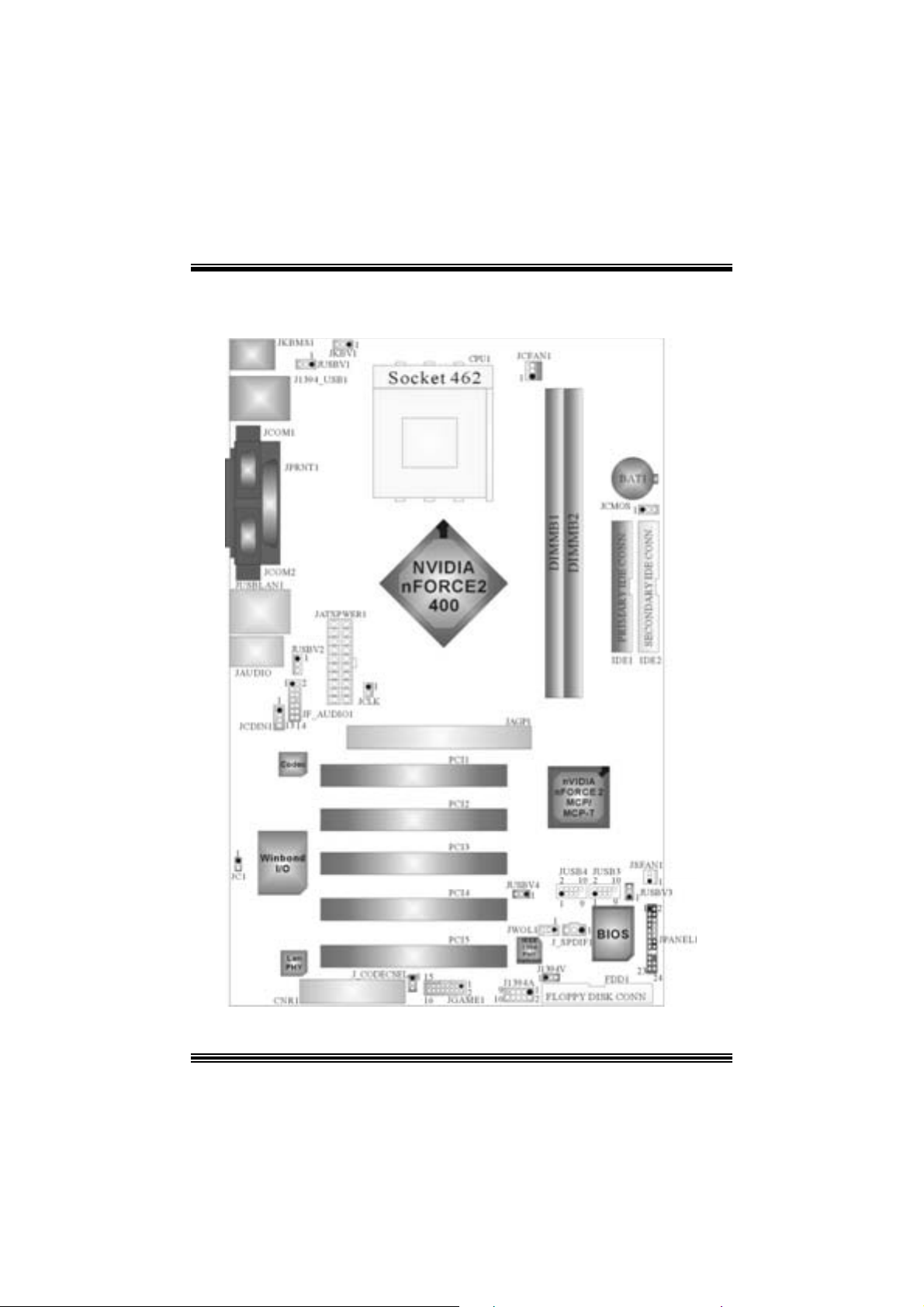
Layout of M7NCD
※NOTE: ●represent s the f irst pin.
1
Page 5
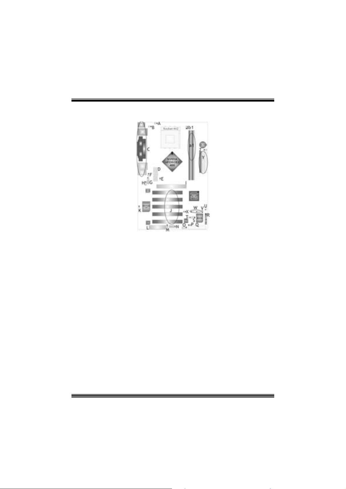
Compone nt Index
A. Power Sour ce Selection fo r Keyboar d M. CNR Codec/ O n board Selection
and Mouse (JKBV1) (J_CODECSEL)
B. Power Sourc e Selection for USB N. Game Port Header (JGAME1) *
(JUSBV1) * O . Front 1394 Header (J1394A) *
C. Back Panel Connector P. Power Source S election for IEEE1394 *
D. A TX Power Connector (JATXPWER1) Q. Floppy Disk Connector (FDD1 )
E. Safe/ User Mode Selection (JCLK) R. Front Panel Con nector (JPANEL1)
F. Powe r Sour ce Selection for USB S. Digital Audio Co nnector (J_SP DIF1) *
(JUSBV2) T. W ake On LAN Header ( JWOL1)
G. Front Audio Head er (JF_AUDIO1) U. S ystem FAN H eader (JSFAN1) *
H. CD-RO M Audio-In Header (JCDIN1) V. Power Source Selection fo r USB
I. Accelerated Graphics Port Slot (JUSBV3)
(JAGP1 ) W. Fron t US B Headers (JUSB3/ J USB4))
J. PCI BUS Slots (PCI 1-5) X. Power Source S election for USB
K. Case Open Connector (JC 1) (JUSBV4)
L. Communication Net work Riser Slot Y. IDE Connectors (IDE1-2)
(C NR1) Z. Clear CMOS ( JCMOS)
a1. DIMM Modules (DIMMB1-2)
b1. CPU Fan Connector (JCFAN1)
* optional
2
Page 6

English
M7NCD Fea tures
A. Har dware
CPU
Pr ov ide s S o cke t-462 .
Su pports the AMD® proc essor up t o XP 3200+.
F ront Side Bus at 266/333/400 MHz.
Chipset
N orth Bridge: nVIDIA nFORCE2 400.
Sout h Bridge: nVIDIA nFORCE2 MCP/ MCP-T.
Main Me m o ry
Support s up t o 2 DDR devices .
Support s 266/ 333/ 400MHz (wit hout ECC ) DD R dev ices.
Maxi mu m me mo ry s i ze o f 2GB.
Super I/O
Chip: Winbond W83 627H F.
Meet Low Pin C ount (LPC) Spec. 1.0
Integrate Hardw ar e Moni tor fun ction s.
Support D ev ic e Power Managem ent (DPM) and AC PI.
1394A Ch ip (op tional)
Chip: RTL8 801B.
Supports 2 ports with transf er up t o 400 m bps.
LAN (optional)
Chip: RTL8 201BL.
Dual Speed - 10/ 100 Mbps .
Half and Full Duplex.
Aut o N egotiation: 10/ 100, F ull/ Half Duplex
Slots
F ive 32-bit PCI bus mas t er s lots.
On e CN R slo t .
One AGP: nAGP3.0 8X interfac e at 533Mb/s.
oSupports AGP 2X, 4X, 8X.
On Board IDE
Supports four IDE di s k dri ves.
Supports PIO Mode 4, Master Mode and Ult ra DMA 33/ 66/100/ 133 Bus Mast er
Mode.
3
Page 7

On Bo ard AC’97 Sound Cod ec
Chip: ALC655.
Compliant with AC ’97 s pec ificat ion.
AC ’97 2. 2 int erfac e.
Support s 6 c hannels.
On Board Peri pherals
a. R e ar si de
2 s erial port s.
1 parallel port. (SPP/EPP/ECP m ode)
Audio ports in v ert ical posit ion.
1 LAN port. (optional)
PS/2 mouse and PS/2 keyboard.
2 USB2.0 por t s.
1 I EEE 1394A (F ireWireTM) Connec t or. (optional)
b. F ront Si d e
1 floppy port supports 2 F DDs with 360K, 720K, 1.2M, 1.44M and 2. 88Mby tes.
4 USB2.0 port s.
1 front audio header.
1 IEEE 1394A (FireWireTM) Connec t or. (optional)
Dimensions
ATX F orm F actor: 19.5cm X 30.5cm (W X L)
B. BIOS & S oftware
BIOS
Award legal Bios .
APM1.2.
ACPI.
USB Function.
Software
S upports C PU SaviorTM, 9t h T ouchTM, FLASHER™, WinFlasher
(optional) and Watc hdog
Offers the highest performance for Windows 98 SE, Windows 2000, W indows Me,
Windows XP, SC O UNIX etc.
TM
.
TM
, St udioF un!
TM
Package contents
HDD Ca b le X1
FDD Cable X1
User’s Manual X1
USB Cable X1 (optional)
Rear I/ O Panel for ATX Cas e X1 (optional)
Fully Setup Driver CD X1
St udioF un! Application CD X1 (optional)
IEEE 1394 C able X1 (optional)
4
Page 8
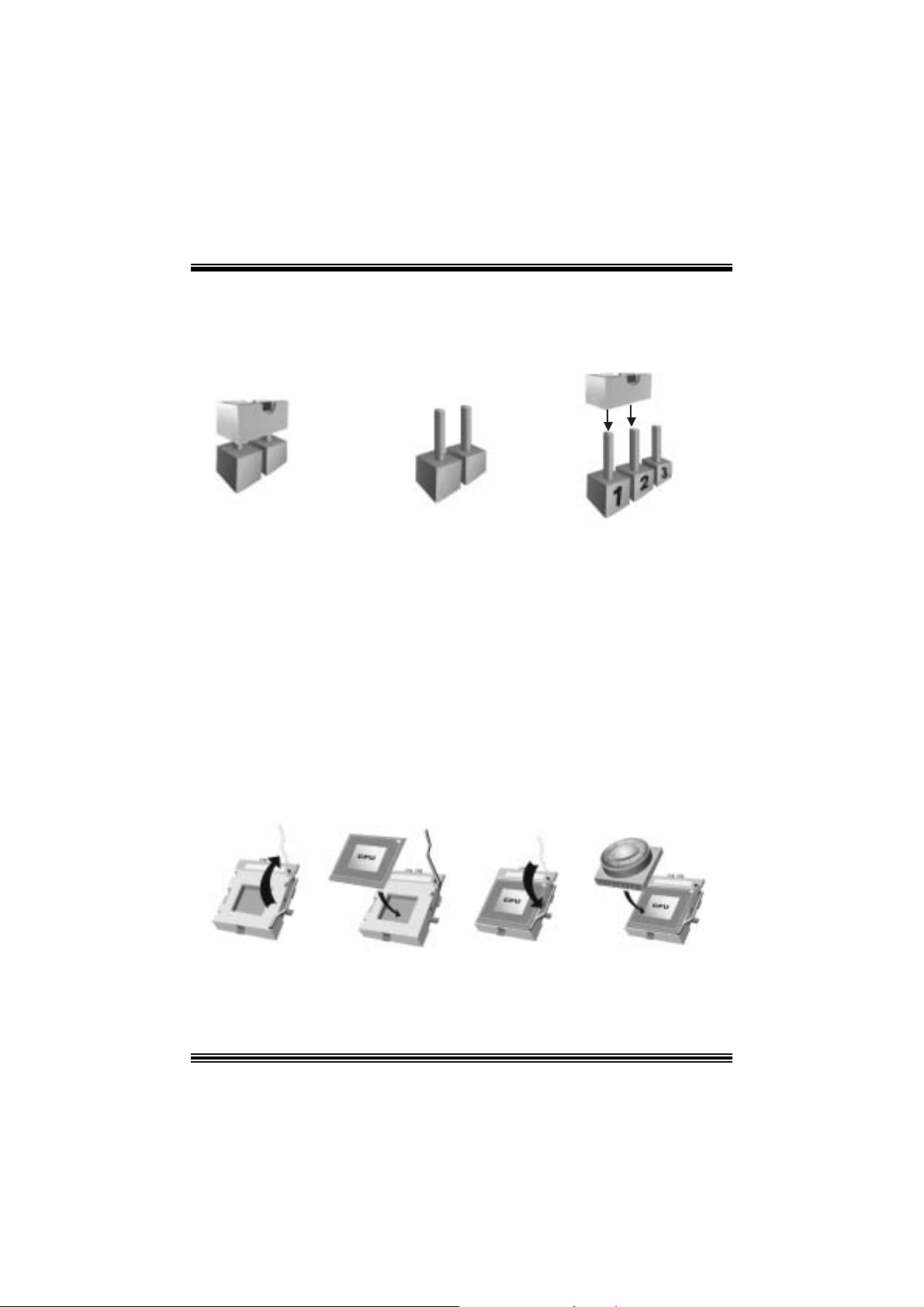
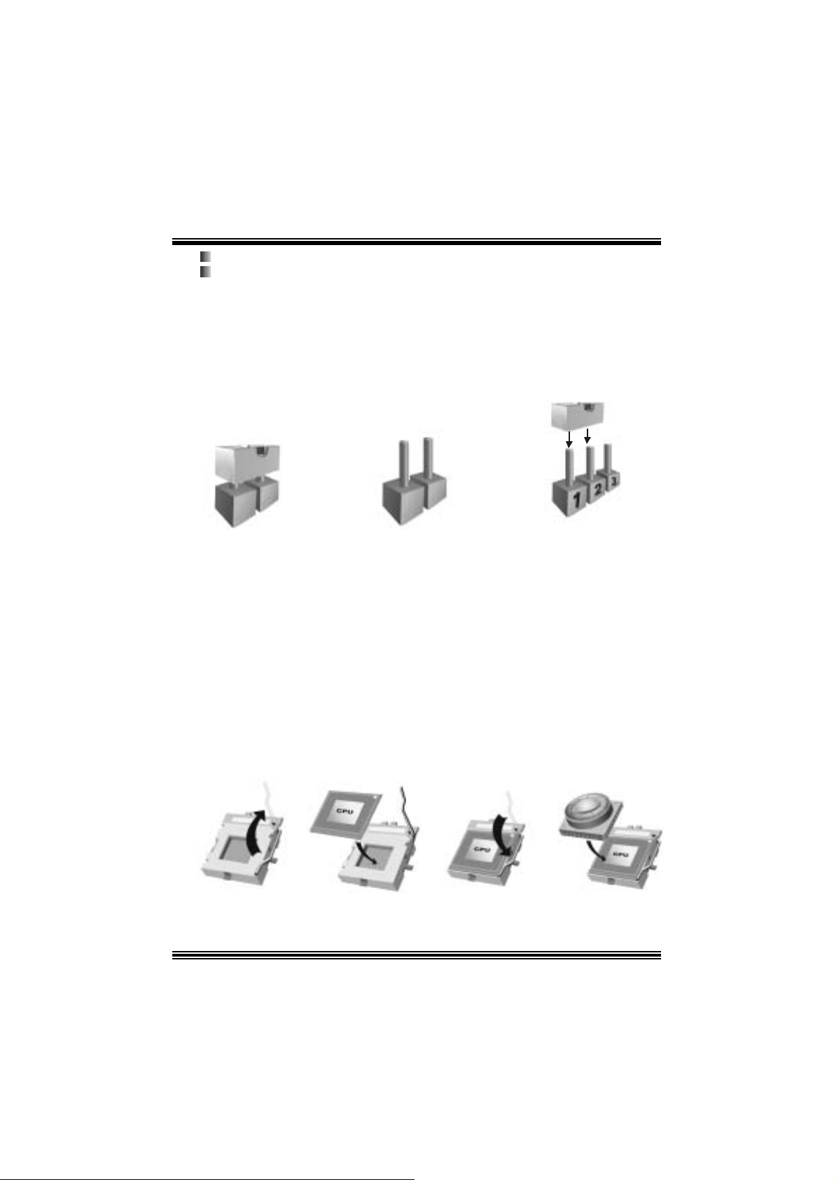
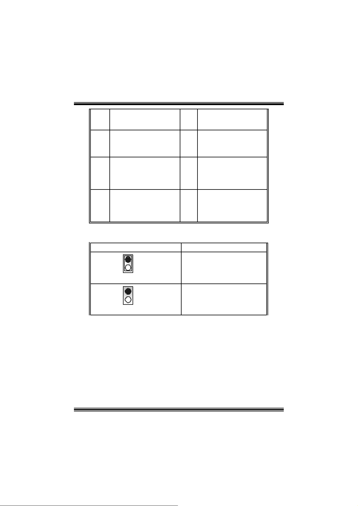
Ho w to setup Jumper
The illustrat ion sho ws how jum pe rs are s e tu p. When the Jum per c ap is placed on pins, the
jumper is “close”. If no jumper cap is placed on the pins, the jumper is ”open”. The
illust rat ion sho ws a 3-pin jumper whos e pin 1and 2 are “close” when jumper c ap is placed
on thes e 2 pins .
Jumper close Jumper open Pin1-2 close
CPU Installation
Step1: Pull the lever sideway s away from the s ock et and then raise the lever up to a
90 -degree angl e.
Step2: Look for the white dot/c ut edge. The whit e dot/cut edge should point towards the
lev er pivot. The C PU will f it only in the c orrect orient ation.
Step3: Hold the CPU down fir ml y, and then close the lever.
Step4: Put t he C PU f an on t he C PU and buck le it. Connect the CPU fan power c able t o
the JCFAN1. This completes the installation.
Step1 Step2 Step3 Step4
5
Page 9
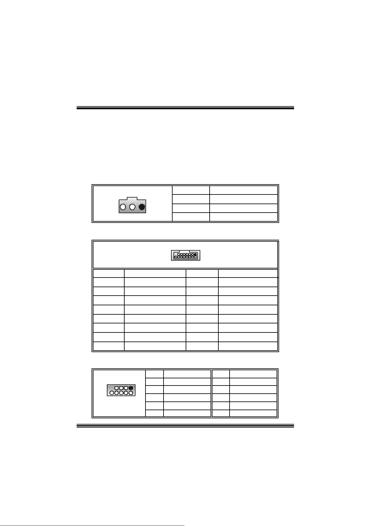
CPU Fan Header: JC FAN1
3
1
JCFAN1
Pin No. A ssi gnm e nt
1
2
3
FAN rpm Rate Sense
Ground
+12V
S ystem Fan Header: JSFAN1 (optional)
Pin No. A ssi gnm e nt
1
JSFAN1
2
3
FAN rpm Rate Sense
1
Ground
+12V
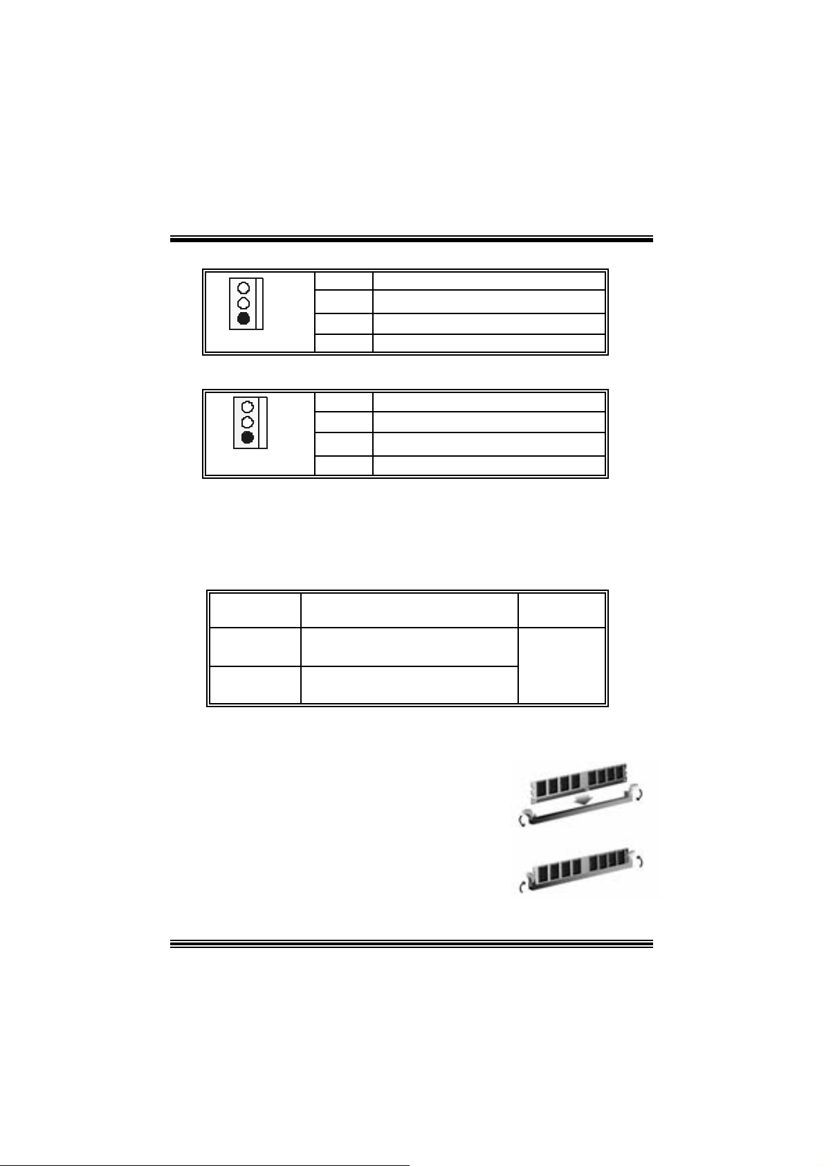
D DR DIMM Mod ules : DIMMB 1 , DIMMB2
DR AM Access Time: 2.5V Un buff ere d DDR 266/333/40 0 MHz Type re qui red.
DRAM Type: 64MB/ 128MB/ 256MB/ 512MB/ 1GB DI MM Module (184 pin)
Total Memory Size wit h Unbuffere d DI MM s
DI MM S ocket
Location
DIMMB1 64MB/128MB/256MB/512MB/1GB
DIMMB2 64MB/128MB/256MB/512MB/1GB
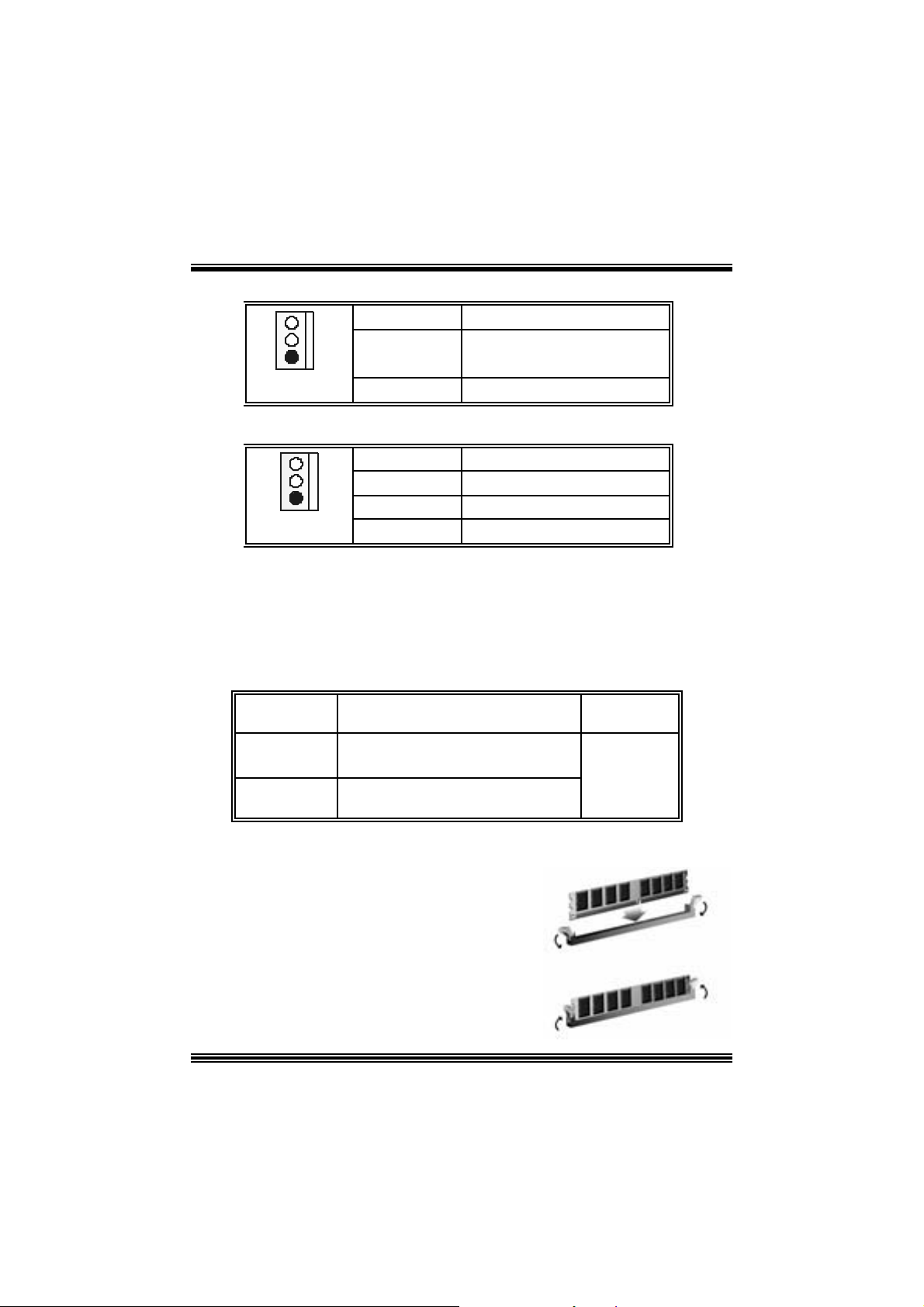
Installing DDR Module
1 . Un lock a DIM M s lot by pres s ing the r eta in ing
clips out ward. Align a DIMM on t he slot such
that the notch on t he DIMM matches the
break on the slot .
2. Insert the DIMM firml y a nd vertica lly into the
slot until the retaining chip snap back in
place and the Dimm is properly seat ed.
DDR Mod u l e To tal Memory
*1
*1
***On ly for refer en ce***
6
Size (MB)
Max is
2GB
Page 10
Jumpers, Headers, Connectors & Slots
Floppy Disk Connector: FDD1
The mot herboard provides a standard f loppy disk connector that supports 360K,
720K, 1.2M, 1.44M and 2.88M floppy disk types. This connector supports the
prov ided f loppy drive ribbon cables .
Hard Disk Connectors: IDE1/ IDE2
The motherboard has a 32-bit Enhanced PCI IDE Controller that provides PIO
Mode 0~4, Bus Mast er, and Ultra DMA 33/ 66/ 100/ 133 functionality. It has t wo
HDD connec t ors IDE1 (primary) and IDE2 (secondary).
The ID E c onnectors can c onnect a master and a slav e driv e, so you c an connect
up to four hard disk drives . The f irst hard drive s hould alway s be c onnected t o
IDE1.
Peripheral Component Interconnect Slots: PCI 1-5
This m ot herboard is equipped with 5 st andard PCI s lots. PCI stands for Peripheral
Component I nterconnec t, and it is a bus standard for expansion cards. This PCI
slot is des ignated as 32 bits.
Accelerate d Graphics Port Slot: JAGP1
Your monitor will attach directly to that video card. This motherboard supports
video cards f or PC I s lots, but it is als o equipped with an Accelerated Graphics Port
(AGP). An AGP c ard will take advantage of AGP technology f or improv ed video
efficiency and perform ance, es pecially with 3D graphics.
Commun ication Netwo r k Rise r Slot: CNR1
The CNR specification is an open I ndust ry St andard Architecture, and it def ines a
hardware scalable riser card interf ace, which support s audio, network and modem
only.
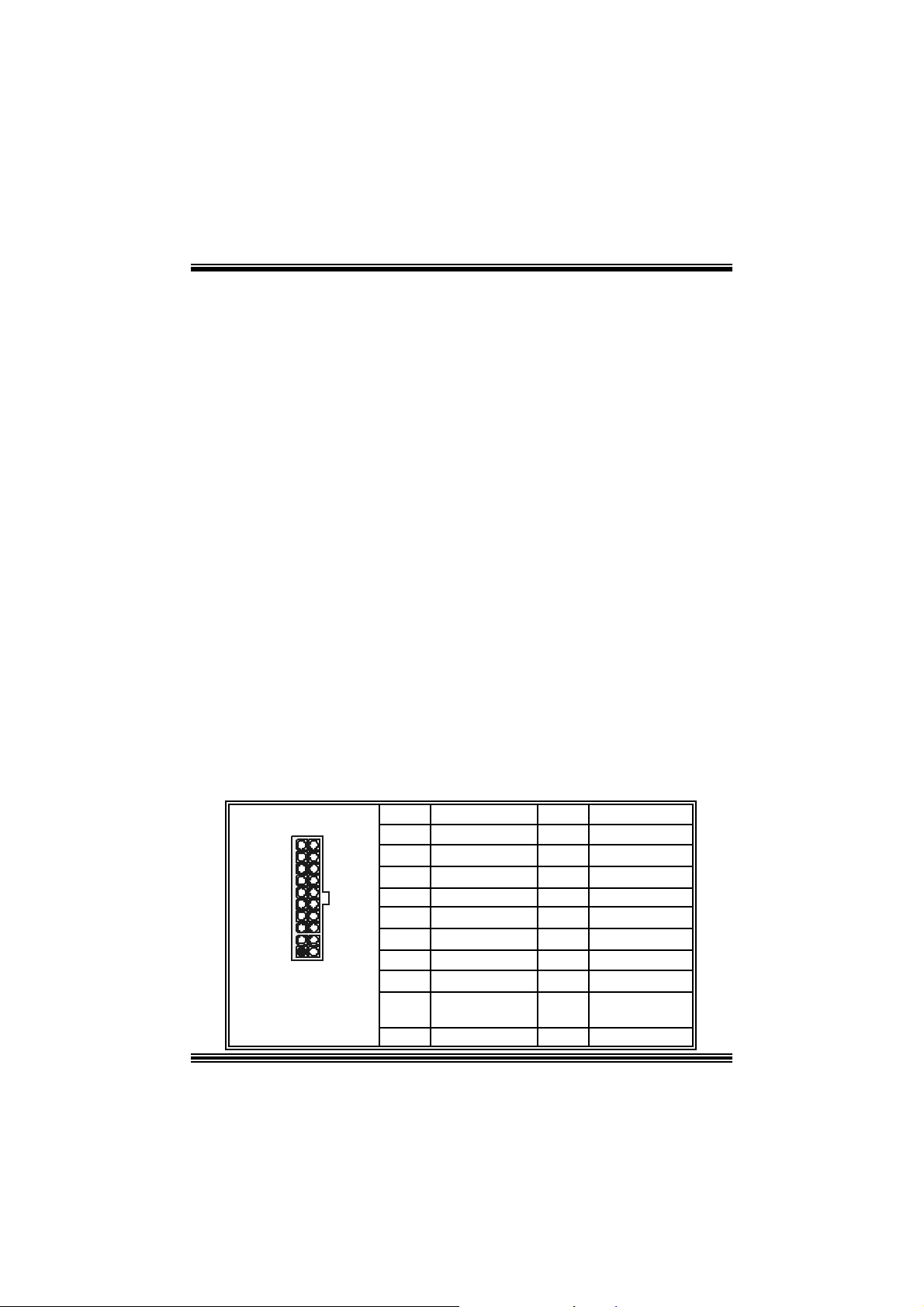
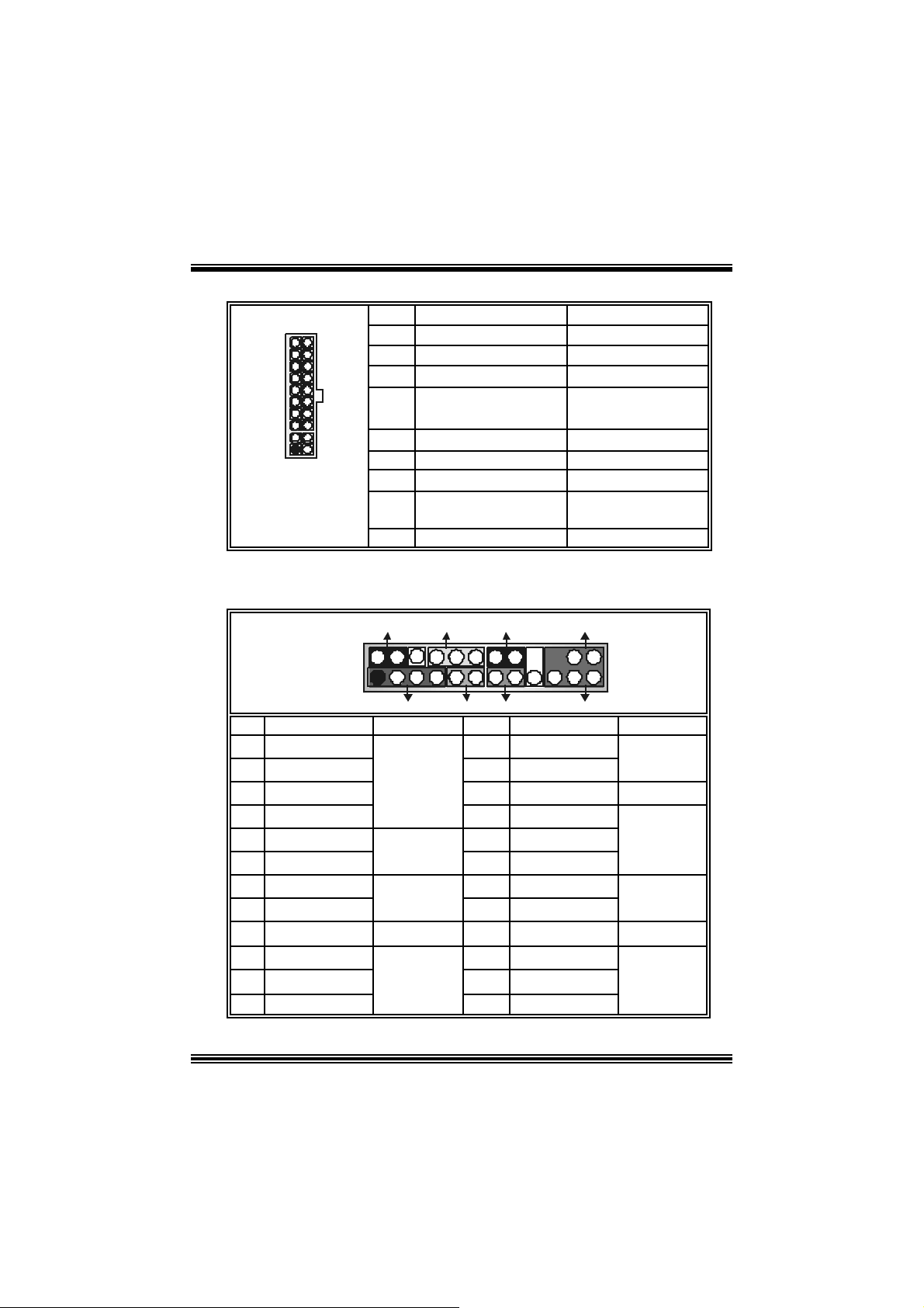
Power Conn ectors: JATXPWER1
10
20
1
11
JATXPWER1
PIN Assignment PIN Assignment
1 +3.3V 11 +3.3V
2 +3.3V 12 -12V
3 Ground 13 Ground
4 +5V 14 PS_ON
5 Ground 15 Ground
6 +5V 16 Ground
7 Ground 17 Ground
8 PW_OK 18 -5V
9 Standby Voltage
10 +12V 20 +5V
7
+5V
19 +5V
Page 11
0
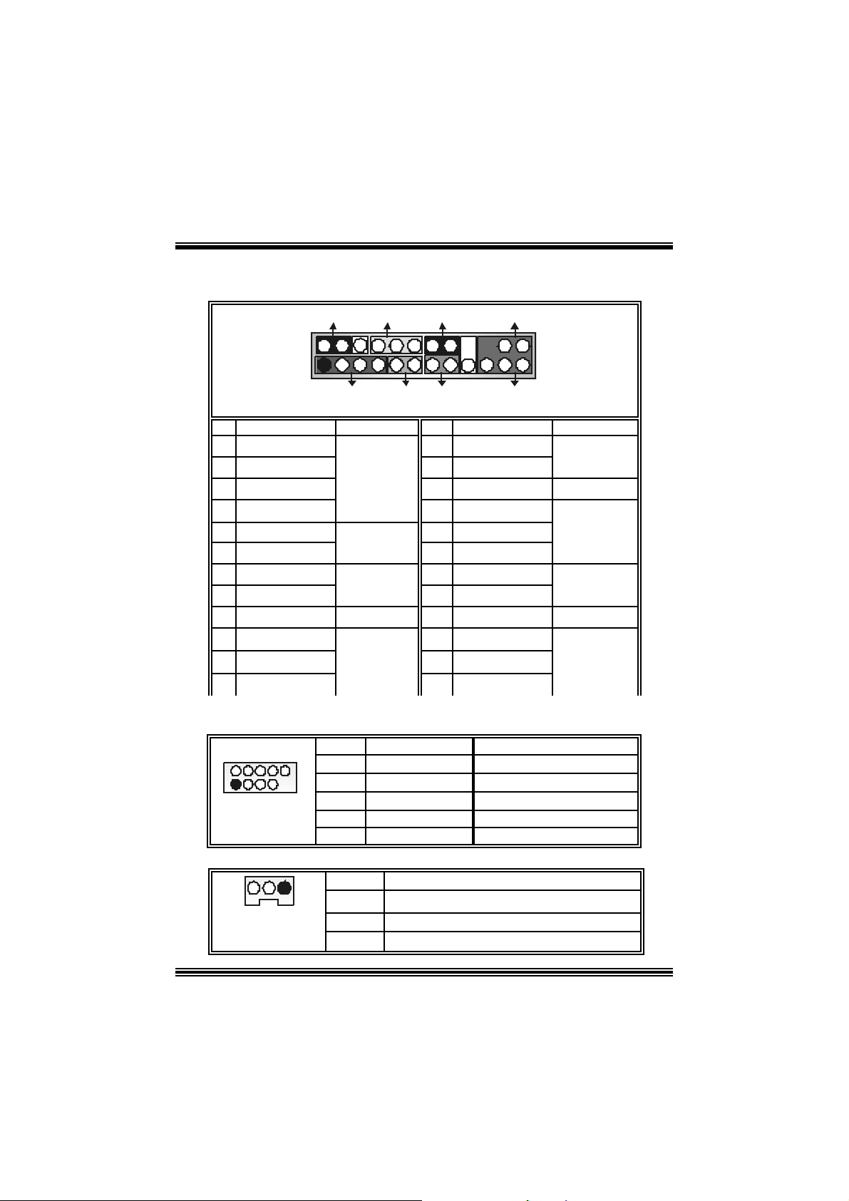
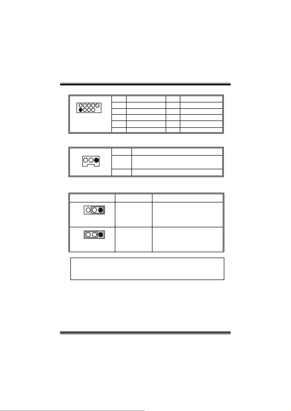
Front Pane l Conne ctor: JPANEL1
SLP
JPANEL1
Pin Assignment Function Pin Assignment Function
1 +5V 2 Sleep C ontrol
3 NA 4 Ground
5 NA 6 NA NA
7 Speaker
9 H DD L E D (+ ) 10 Power LED (+)
11 H DD LED (-)
13 Ground 14 Power Button
15 Reset Control
17 NA 18 KEY
19 NA 20 KEY
21 +5V 22 Ground
23 IRTX
2
1
PWR_LED
(+) (-)(+)
SPK
Hard Dr ive
(+) (-)
HLED
RST
Speaker
Connector
8 Power LED (+)
LED 12 Power LED (-)
Reset
Button 16 Ground
IrDA
Connector
24 IRRX
IRON/ OFF
IR
24
23
Sleep
Button
POWER
LED
Power-on
Button
IrDA
Connector
Front USB Header: JUSB3/ JUSB4
2
1
JUSB 3/ JUSB4
Pin Assignment Pin Assignment
1
1
3
9
5
7
9
+5V(fused)
USBP4-
USBP4+
Ground
KEY
2
4
6
8
10
+5V(fused)
USBP5-
USBP5+
Ground
NA
Wake On LAN He ader: JWOL1
13
JWOL1
Pin Assignment
1 +5V_S B
2
3 Wake up
8
Ground
Page 12
d
d
d
d
h
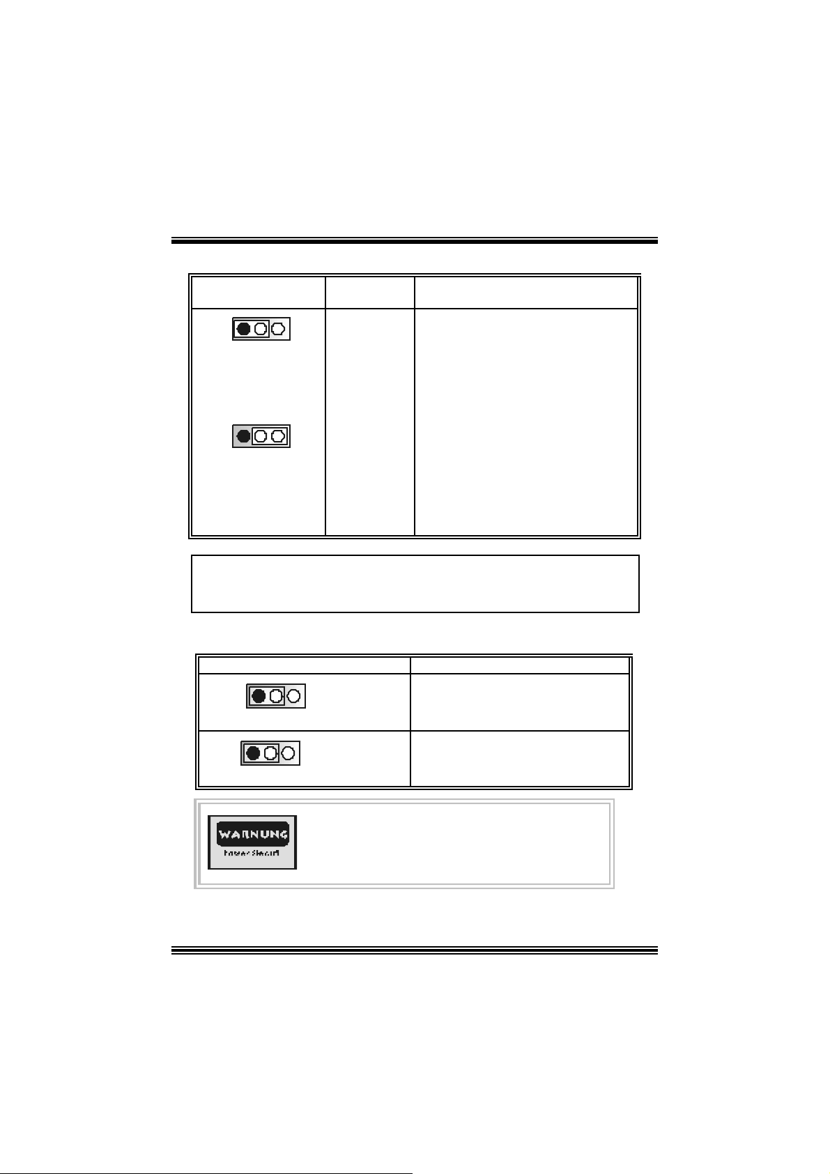
Power Source Selection for Keyboard and Mouse: JKBV1
JKBV1 Assignment Description
31
Pin 1-2 c los e
31
Pin 2-3 c los e
+5V Standby
Voltage
+5 V
+5V for keybo ard and mouse
PS/2 Mous e and PS/2 Key board are
powered with +5V standby v oltage
No t e: In o rder to su pport th i s fun cti o n “Pow e r-o n sy ste m v i a ke yb oa rd and
mouse”, “JKBV1” jumper cap should be placed on pin 2-3.
Power Source Selection for USB: ( JUSB V1 =>optional)/ JUS BV2/
JUSBV3/ JU SBV 4
JUSBV1/JUSBV2/
JUSBV3/ JUSBV4
1 3
Pin 1-2 c los e
Assignment Description
+5V JUSBV1: 5V for US B connector locate
a t th e J 139 4_U SB1 port
JUSBV2: 5V for USB connector lo cate
at the JUSBLAN1 port
JUSBV3: 5V for USB connector lo cate
at t he JUSB3 port
JUSBV4: 5V for USB connector lo cate
at t he JUSB4 port
1 3
Pin 2-3 c los e
+5V Standby
Voltage
JUSBV1: J1394_USB1 port powered
with s t andby v olt age of 5V
JUSBV2: JU SBLAN1 port powered wit
standby v olt age of 5V
JU SBV3: JUSB3 port powered with
standby v olt age of 5V
JU SBV4: JUSB4 port powered with
standby v olt age of 5V
Note: In orde r to support this functio n “P owe r-on the system via USB device ”,
“JUSBV1/JUSBV2/ JUSBV3/ JUSBV4” jumper cap should be placed on pin
2-3 respectively.
9
Page 13
r
p
Power Source Sel ection for IEEE1394: J1394V
J1394V Assignment Description
1 3
Pin 1-2 c los e
1 3
Pin 2-3 c los e
+3. 3V J1394V: 3.3V for IE EE1394A connecto
+3.3V
Standby
Voltage
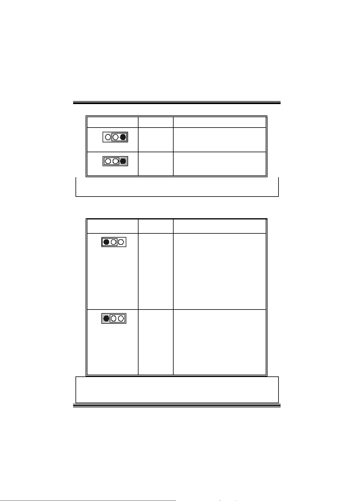
Clear CMOS Jumper: JCMOS
JCMOS Assignment
1 3
Pin 1-2 C lose
1 3
Pin 2-3 C lose
The fo llowing procedu res a re for res etting the
BIOS
assword . It is i mportant to follow these
ins truct ions c lose ly.
※ Clear CMOS Procedures:
1. R emov e AC power line.
2. Set the jumper to “Pin 2-3 C lose”.
3. Wa it for fi ve seconds.
4. Set the jumper to “Pin 1-2 C lose”.
5. Power on t he AC .
6. R eset your des ired password or clear t he C MOS dat a.
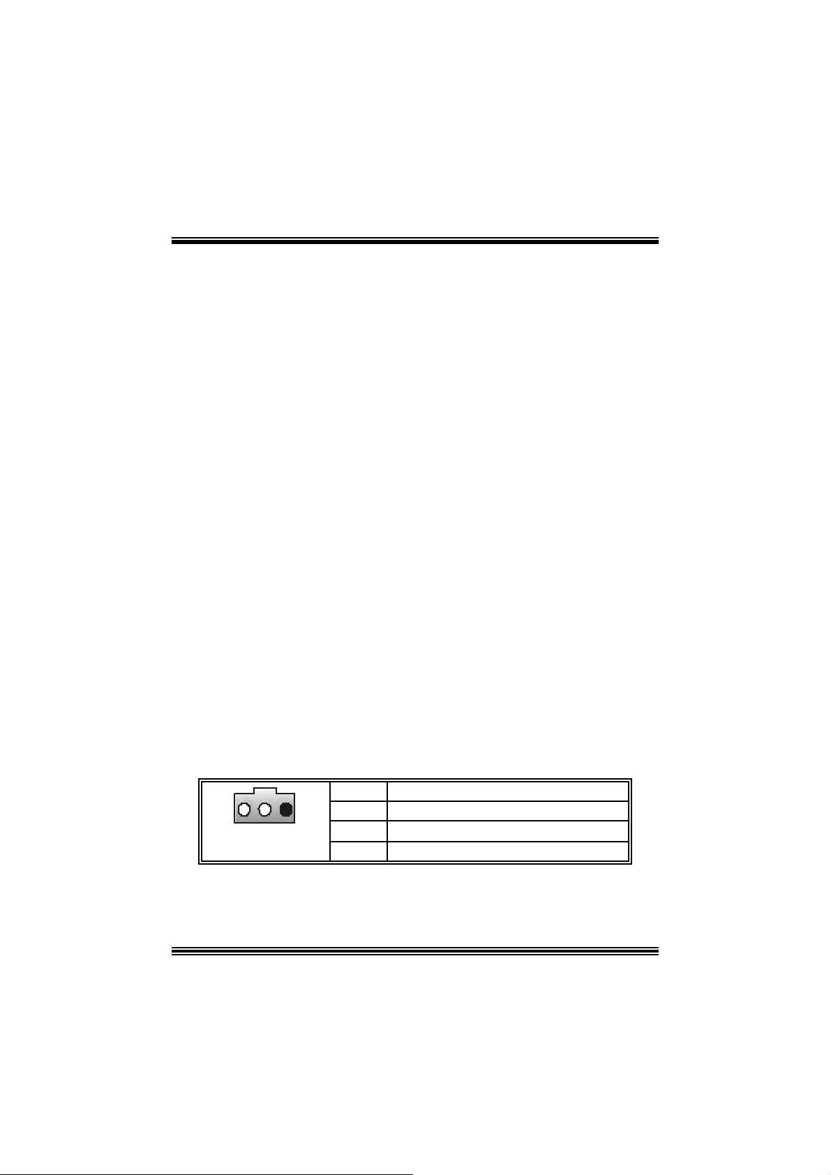
Ca se Op e n Connec to r: JC1
locate d at the J1394A h eader.
J1394V: J1394A header powered with
st andby voltage of 3. 3V
Norm al Operation (def ault)
Clear CMOS Data
1
JC1
Pin
1
2
10
Assignment
Case Open Signal
Ground
Page 14

CD-ROM Audio-In Heade r: JCDIN1
1
4
JCDIN1
Pin Assignment
1
2
3
4
Left Channel In put
Ground
Ground
Right Channel In put
Front Panel Audio Header: JF_AUDIO1
12
13 14
Pin Assignment Pin Assi gnment
1
3
5
7 Reserv ed 8 Key
9
11
13
Mic I n / C e nter
Mic Power/ Bass
Right Line Out/ Speaker
Ou t Ri ght
Left Line Out/ Speaker
Out Left
Right Line I n/ R ight Rear
Speaker
Left Line I n/ Left R ear
Speaker
JF_AUDI O1
2
4
Right Line Out/ Speaker
6
Left Line Out/ Speaker
10
Right Line I n/ R ight Rear
12
14
Left Line I n/ Left R ear
Audio Power
Ou t Ri ght
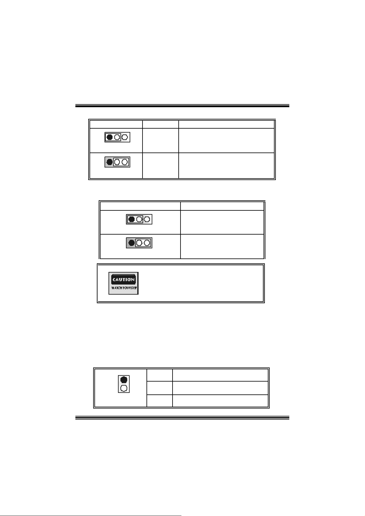
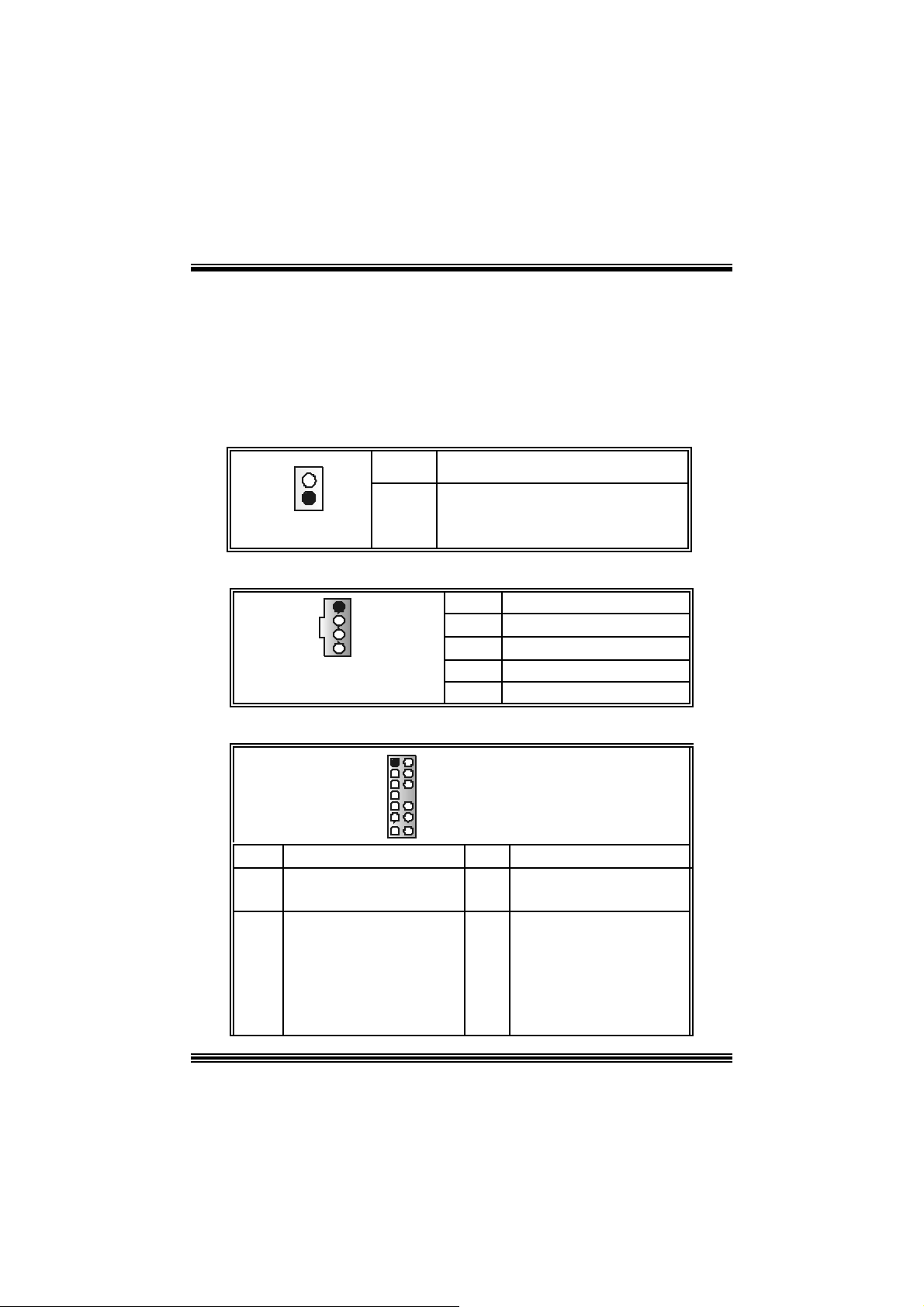
Safe/ User Mode Selection: JCLK
JCLK Assignment
1
Pin 1-2 Clos e
1
Pin 1-2 Open
Safe mode
User Mode (def ault )
(133/ 166/ 200 MHz)
Ground
Out Left
Speaker
Speaker
11
Page 15
X
Note: W hen ov erclock function failed and system is unable to boot-up, please
follow the instructio n below:
1. Tu r n off th e system.
2 . Closed the JCLK jump er.
3. Turn on the sys t em.
4. Enter CMOS s et up menu and load def ault s sett ings .
5. Tu r n off th e system.
6. Open th e J C LK j um per.
7. Turn on the sys t em.
Digital Audio Connector: J_SPDIF1 (optional)
31
Pin Assignment
1
2
3
+5V
SPDIF_O UT
Ground
Game Header: JGAME1 (option al)
15
Pin Assign m ent Pin Assignment
1
3
5
7
9
11
13
15
Joy stick B C oordinate X
Joy stick B C oordinate Y
+5V
Joy stick B Butt on 1
MIDI Output
Joy stick B Butt on 2
MIDI Input
NA
1
216
2
4
6
8
10
12
14
16
Joystick A Button 1
Joy st ick A Coordinate
Ground
Ground
Joy st ick A Coordinate Y
Joystick A Button 2
Front 1394 Header: J1394A (optional)
10
J1394A
Pin Assignment Pin Assignment
1
19
3
2
5
7
9
A1+
Ground
B1+
+1 2V
KEY
2
4
6
8
10
+5V
+5V
A1-
Ground
B1-
+1 2V
NA
12
Page 16

CNR Codec/ Onboard Sel ection: J_CODECSEL
J_CODECSEL Assignment
1
3
Pin 1-2 Close
1
3
Pin 2-3 Close
Onboard C odec is used (def ault)
CNR Codec is used
B ack Panel Connectors
PS/2
Mouse
PS/2
Key board
1394
(op tional )
USB
(op tional)
Pa ra l le l Po rt
COM1 COM2 USB
LAN
(opt io nal)
Line In
Speaker Out
MIC In
13
Page 17

Deutsch
Spe zifikation en von M7N CD
A. Har dware
CPU
Unterstützung für Sockel 462.
U nterstüt zung für den AMD® Prozessor bis zu XP 3200+.
F SB von 266/333/400 MHz.
Chipsatz
N orthbridge: nVIDI A nF ORC E2 400.
Sout hbridge: nVIDIA nFORCE2 MC P/ MCP-T.
Hauptspeicher
Unter stützung fü r 2 DDR Ge räte.
Unterstützung für 266/333/ 400 MH z (ohne EC C) DDR Geräte.
High-Performanc e 128-Bit DDR400 mit der Twin-Bank Architekt ur.
D ie m ax imale Speichergröße ist 2GB.
Super I/O
Chip: Winbond W83 627H F.
1394A Ch ip (op tional)
Chip: RTL8 801B.
U nterstüt zung für 2 1394-Ports m it der D at enübert ragungsrate bis auf maxim al
400Mbps.
LAN (optional)
Chip: RTL8 201BL.
Dopplete Geschwindigk eit von 10/100 Mbps.
Voll und H alb-D uplex.
Aut o-N egotiation: 10/ 100, Voll/Halb-Duplex
Slots
F ünf 32-Bit PCI -Bus-Slots .
Ein CN R-S lot .
Ein AGP-Slot: nAGP3. 0 8X Interf ace bei 533Mb/s.
o U nterstützung für 2X/4X/8X AGP.
Onboard-IDE
Unterstützung fü r vi er IDE Diskettenl au fwe rke.
U nterstüt zung für PIO Modus 4, Mas t er Modus und Ultra DMA 33/66/100/133 Bus
Mast e r Mo dus .
14
Page 18

Onboard AC’97 Sound Codec
Chip: ALC650.
Ent s pricht der Spezif ikation von AC ’97.
Unterstützung für AC97 2.2 Interfac e.
Unterstützung für 6-Kanal Audio.
Onboard-Peripheriegeräte
a. R ü c kwan d
2 s erielle Sc hnittstellen.
1 parallele Sc hnittstelle. (SPP/EPP/ECP-Modus )
Audio-Ports auf vert ik ale Posit ion.
1 LAN -Port. (opt ional)
Uerstützung f ür PS/2-Maus und PS/2-Tastatur.
4 USB2.0-Ports.
1 I EEE 1394A (FireW ire) Ansc hlus s. (optional)
b. Vorder seit e
1 F loppy-Port m it Unterstützung f ür 2 Dis k et t enlauf werke.(360KB, 720KB, 1.2MB,
1.44MB und 2.88MB).
2 USB 2.0- P or ts ..
1 front audio header.
1 IEEE 1394A (FireWire) Anschlus s. (opt ional)
Abmessungen
ATX Form-Factor: 19.9cm X 30. 4cm (W X L)
B. BIOS & S oftware
BIOS
Award legal BI OS.
Unterstützung für APM1. 2.
Unterstützung f ür ACPI.
Unterstützung für die USB Funktion.
Software
Unterstützung für CPU Savio rTM, 9th Touc hTM, FLASHE R™, Win FlasherTM ,
StudioFun!
Unter stützung für die am mei s ten verbreiteten Be triebsyste me wie Wi ndows 98SE,
Windows 2000, W indows ME, Windows XP and SC O UNIX usw. .
TM
(opt ional) und Wat c hdogTM.
Verpack ungsinhalt
HD D Kable X1
FDD Kable X1
Benut zer Handbuch X1
USB Kable X1 (optional)
I/O-Rückwand für ATX Gehäuse X1 (optional)
15
Page 19
Treiber C D für Installation X 1
St udioF un! Anwendung CD X 1 (opt ional)
Ei nst e l lu ng de r Jum per
Die Abbildung verdeutlicht, wie Jumper eingestellt werden. Pins werden durch die
Jum per-Kappe v erdeckt, ist der Jum per ”geschlossen”. Keine Pins werden durch die
Jum per-Kappe verdeckt, is t der Jum per “geöffnet”. Die Abbiildung zeigt einen 3-Pin
Jumper dessen Pin1 und Pin2 ”geschlossen“ sind, bzw. es bef indet sich eine
Jum per-Kappe auf dies en beiden Pins.
Jumper geschlossen Jumper geöffnet Pin1-2 geschlossen
Instal latio n de r C PU
Sc hritt 1 : Z iehen Sie den H ebel s eitlich vom Sockel weg. Heben Sie den Hebel dann
in 90-Grad-Winkel nac h oben.
Sc hritt 2 : Suchen Sie nac h der scharfen Kant e, die auf D rehpunkt des Hebels
weisen m uss . Die CPU passt nur, wenn s ie ric htig aus geric ht et ist.
Sc hritt 3 : D rück en Sie die CPU f est in den Sock el und s c hließ en Sie den Hebel.
Schritt 4: Stecken Sie Ihren C PU -Lüft er auf die CPU. Schließ en Sie die
Stromv ersorgungssteck er f ür CPU-Lüfter an JCF AN1 an. D ann beenden
Sie die I nstallation.
Schritt 1 Schritt 2 Schritt 3 Schritt 4
16
Page 20
CPU- Lüfter Header: JCFAN1
3
1
JCFAN1
Pin Beschreibung
1 Masse
2 +12V
3
Lüfter R PM Geschwindigk eit Sensor
System-Lüfter Header: JSFAN1
Pin Beschreibung
1 Masse
1
JSF AN1
2 +12V
3 Lüft er RPM Geschwindigkeit Sens or e
DDR- DI MM- Module s: DIMMB1, DIMMB2
DRAM-Zugriffszeit: 2.5V Unbuffe red D DR 266/333/400 MHz Typ erfordlich.
DRA M- Ty p: 6 4M B/ 128MB / 256M B/ 5 12M B/ 1 GB DIM M - M odule (184-P in)
Gesamte Speichergröße von Unbuffered-DIMMs
DIMM-Sockel
Standort
DIMMB1 64MB/128MB/256MB/512MB/1GB
DIMMB2 64MB/128MB/256MB/512MB/1GB
DDR-Module Speichergröße
*1
*1
*** Nu r als Refer enz ***
In sta l l ati on von D DR- Modul
1. Öff nen Sie einen DIMM-Slots, indem Sie die
seitlich Chips nach außen drüc ken. Richten Sie
das DIMM-Modul so über dem Slot aus, dass
das Modul m it der Kerbe in den Slot passt.
2. Drüc ken Sie das DI MM-Modul in den Slot, bis die
seit lichen Clips zusc hnappen und das Modul f est
sitzt.
17
(MB ))
Ma ximal ist
2GB
Page 21
Jump ers, H eade rs, Anschlüs s e & S lot s
Diskettenanschluss: FDD1
Das Motherboard enthält einen st andardmäßigen Diskettenans chluss, der 360K-,
720K-, 1.2M-, 1.44M- und 2.88M-Disketten unterstützt. Dieser Anschluss
unt ers tützt die mit gelief erte Bandkabel des Diskettenlauf werks..
Fe stplatt enanschlüsse: IDE1 und ID E2
Das Mainboard hat einen 32-bit Enhanced PCI IDE-Controller, der die Modi
PIO0~4, Bus Mast er sowie die U ltra DMA/33/ 66/100/133- Funkt ion zur Verfügung
stellt. Dieser ist mit zweii HDD-Anschlüssen versehen IDE1 (primär) und IDE2
(sekundär).
Die ID E-Anschlüsse k önnen eine Master- und eine Slav e-Festplatte v erbinden, so
dass bis zu 4 Festplatten angeschlossen werden können. Die erste Festplatte
sollte im m er an IDE1 angeschlossen werden.
Periphera l Component Int erconnect Slots: P CI1-5
Dieses Motherboard ist m it 5 standardmäß igen PCI-Slots ausgestattet. PC I steht
für Peripheral Component Interc onnect und bezieht sich auf einem Busst andard für
Erweiterungskarten, der den älteren ISA-Busstandard in den meisten
Schnittst ellen ers etzt hat. Dieser PCI-Slot ist f ür 32 bits v orgesehen.
Accelerate d Graphics Port Slot: JAGP1
Ihr Monitor wird direkt an die Grafikkarte angeschlossen. Dieses Motherboard
unterstützt Grafikkarten f ür PCI-Slots, aber es ist auch mit einem Accelerated
Graphic s Port ausges tattet. AGP-Karten v erwenden die AGP-Technologie, um die
Wirks amk eit und Leistung v on Videosignalen zu v erbessern, besonders wenn es
sich um 3D-Graf iken handelt.
Commun ication Netwo r k Rise r Slot: CNR1
Die CN R -Angaben ent s prec hen einer of f enen Industry Standard Architecture, und
sie definieren eine Hardware-skalierbare Riser-Card-Schnittstelle, welche nur
Audio, N etzwerk und Modem unt erstützt .
Digital Audio A nschluss: J_SPDIF1 (optional)
31
Pin Belegung
1
2
3 Masse
18
+5V
SPDI F_Ausgabe
Page 22
Stromversorgungsanschluss: JATXP WER1
PIN Belegung PIN Belegung
1 +3.3V 11 +3.3V
2 +3.3V 12 -12V
3 Masse 13 Masse
4 +5V 14 PS_ON
5 Masse 15 Masse
6 +5V 16 Masse
7 Masse 17 Masse
8 PW_OK 18 -5V
9 +5V reserv iert e
Spannung
10 +12V 20 +5V
19 +5V
10
1
JATXPWER1
20
11
Anschlüsse für die Vo rderseite: J PANEL1
SLP
JPANEL1
2
123
Pin Belegung Funktion Pin Belegung Funktion
1 +5V 2 Sch l af - Kontro ll
3 Kein 4 Masse
5 Kein 6 Kein Kein
7 Lautsprecher
9 H DD L E D (+) 10 Power LED (+)
11 HDD LE D ( -)
13 Masse 14 Power-Knopf
15 Reset-Kontroll
17 Kein 18 Schlüsse
19 Kein 20 Schlüsse
21 +5V 22 Masse
23 IRTX
Lautsprecher-
PWR_LED
(+) (-)(+)
SPK
Anschluss
Festplatte
LED
Rückstell-
knopf
IrDA-
Anschluss
(+) (-)
HLED
RST
8 Power LED (+)
12 Power LED (-)
16 Masse
24 IRRX
IRON/ OFF
IR
24
Schlaf -
Knopf
POWER
LED
Power-On
Knopf
IrDA
Anschluss
19
Page 23
Front USB Header: JUSB3
2
1
JUSB3
10
9
Pin
1
3
5
7
9
Belegung
+5V(geschmelzt)
USB-
USB+
Masse
Kein Pin
Pin
2
4
6
8
10
Belegung
+5V(geschmelzt))
USB-
USB+
Masse
Kein
Wake On LAN He ader: JWOL1
13
JWO L1
Pin
1 +5V_S B
2
3 Aufwecken
Bel egung
Masse
Auswahl von Stromsmodi fü r Tastatur/ Maus: JKBV1
JKBV1 Pin-Belegung Beschreibung
31
Pin 1-2
geschlossen
31
Pin 2-3
geschlossen
+ 5V re s erv i ert e
Spannung
+5V
+5V für Tastatur und Maus
Durch +5V reserviert e Spannung für
PS/2-Maus und PS/ 2-Tas t at ur zum
Erwecken vo m System
Anmerkung: Um die Funkti on ―“ E rwecke n dur c h T as t at ur/Maus“ ―
zu aktivi eren, mü ssen Pins 2- 3 von J KBV1 du r ch die Jumpe r kappe
ver deckt w erden.
20
Page 24
Auswahl von Stromsmodi fü r USB: JUS BV1/ JUSBV2/ JUSBV3
JUSBV1/JUSBV2/
JUSBV3
1 3
Pin 1-2 geschlossen
1 3
Pin 2-3 gesc hlossen
Pin-Belegung Beschreibung
+5 V
+ 5V r eserv i ert e
Spannung
JUS BV1: 5V für USB- Port von
J1394_USB1
JUS BV2: 5V für USB- Port von
JUSBLAN1
JUSBV3: 5V für USB-Port von JUSB3
JU SBV1: 5V reservierte Spannung f ür
J1394_USB1 zum Erwecken
JU SBV2: 5V reservierte Spannung f ür
JUSBLAN1 zum Erwecken
JU SBV3: 5V reservierte Spannung f ür
JU SB3 zum Erweck en
Anmerkung: Um die Funkt ion ―“Erw ec ken durc h USB-G erät e“―zu akt iv ieren,
müssen Pins 2-3 von JUSBV1/JUSBV2/J USBV3 durch die Jumperkappe
verdeckt werden.
Jumper zum Löschen des CMOS: JCMOS
JCMOS Beschreibung
1 3
Pin 1-2 geschlossen
1 3
Pin 2-3 gesc hlossen
Die folgende Schritte leiten Sie, das Kennwort für
B IOS-Sys t em zur ückzus et zen. Es i s t wicht ig , die
Anweisung zu f olgen.
Normale Operation (Default )
CMO S-Daten Lös c hen
21
Page 25
※ Prozedu ren zum Löschen des CMOS:
1. Aussc halten Sie das Syst em.
2. Lassen Sie Pin 2-3 von JC OMS1 ges hclossen sein.
3. Bitte wart en Sie 15 Sekunden.
4. Lassen Sie Pin 1-2 von JC OMS1 ges hclossen sein.
5. Einschalten Sie das System wieder.
6. Zurücksetzen Sie ihr gewunschtes Kennwort oder löschen Sie die
CMOS-Daten.
Warnmeldung für Chassis-Öffnen Anschluss: JC1
Pin
Belegung
Gehäus e Öffnen Signal
Masse
1
JC1
1
2
CD-ROM Audio-In Heade r: JCDIN1
Pin Belegung
1
2
3
4
Link-Kanal Eingabe
Masse
Masse
Rec ht -Kanal Eingabe
1
4
JCDIN1
Front Panel Audio Header: JF_AUDIO1
12
13 14
Pin Belegung Pin Belegung
1
3
5
Mikrofon-Eingang/
Zentrum
Mikrofon-Betriebsspannung/
Bass
Audio-Signal des recht en
Kanals zur Vorderseite /
Laut s precher-Signal des
recht en Kanals zur
Vorderseite
JF_AUD IO1
2
Audio-Betriebsspannung
4
Audio-Signal des recht en
6
Kanals zur Vorde rseite /
Lauts precher-Signal des
rechten Kanals zur
Masse
Vorderseite
22
Page 26
7
9
11
13
Rese rvie r et für spä t.
Verwendung durc h
Kopfhörer-Verstärker
Audio-Signal des linken
Kanals zur Vorders eite /
Laut s precher-Signal des
linken Kanals zur Vorderseit e
Audio-Signal des recht en
Kanals von der Vorders eit e /
Laut s precher-Signal des
recht en Kanals von der
Vorderseite
Audio-Signal des linken
Kanals von der Vorders eit e/
Laut s precher-Signal des
linken Kanals von der
Vorderseite
Safe / User Modi Auswahl: JCLK
JCLK Beschreibung
1
Pin 1-2 gesc hlossen
8
10
Kanals zur Vorde rseite /
Lauts precher-Signal des
link en Kanals zur Vorderseite
Audio-Signal des recht en
12
Kanals v on der Vorderseit e/
Lauts precher-Signal des
14
Kanals v on der Vorderseit e/
Lauts precher-Signal des
Schlüsse
Audio-Signal des linken
recht en Kanals von der
Vorderseite
Audio-Signal des linken
linken Kanals von der
Vorderseite
Safe Mode
1
Pin 1-2 geöff net
Anmerkung: W enn Übertakt Funk tion nicht gelungen ist, und das System kann
nic ht arbeit en , folgen Sie bitt e die unt enstehende Bedienungsanleitung :
1. Auss chalt en Sie das Syst em .
2. Lass en Sie den Jum per JCLK ges c hloss en sein.
3. Anschal te n Si e das Sy stem.
4. Eingeben Sie CMOS Set up Menü und wählen Sie das Def ault-Settings.
5. Auss chalt en Sie das Syst em wieder.
6. Lass en Sie den Jum per JCLK geöffnet s ein.
7. Anschal te n Si e das Sy stem.
23
Us er M ode (Def ault)
(133/ 166/ 200 MHz)
Page 27

Game Header: JGAME1 (option al)
2
4
6
8
10
12
14
16
1
216
+5V
Joystick A Knopf 1
Joy stick A Koordierung X
Masse
Masse
Joy stick A Koordierung Y
Joystick A Knopf 2
+5V
15
Pin Belegung Pin Belegung
1
3
Joystick B Koordierung X
5
7
Joystick B Koordierung Y
9
11
13
15
+5V
Joy stick B Knopf 1
MIDI Aus gabe
Joy stick B Knopf 2
MIDI Eingabe
Kein
Front 1394 Header: J1394A (optional)
9
10
J1394A
Auswahl CNR /Onboard-Codec: J_CODECSEL
J_CODECSEL Beschreibung
Pin
1
2
1
3
5
7
9
Belegung
A1+
Masse
B1+
+12V
Schlüsse
Pin
2
4
6
8
10
Belegung
A1-
Masse
B1-
+12V
Kein
1
3
Pin 1-2 gesc hlossen
1
3
Pin 2-3 ges c hloss en
Verwendung von Onboard-Codec
(Default)
Verwendung von CN R -Codec
24
Page 28

Anschlüsse für die Rückwand
J1394_USB1
PS/2
Maus
1394
(optional)
JPRNT1
Parallel Port
JUSBLAN1
LAN
(optional)
Line In
S peaker Out
MIC In
PS/2
Tastatur
JKBMS1
USB
COM1
JCOM1
COM2 USB
JCOM2
JA UDIO
25
Page 29

Français
Car act ér istiq ues de M7NCD
A. Ma tériel
Processeur
Avec socket-462.
Prise en charge du processeur AMD® jusqu'à XP 3200+.
Bus frontal à 266/ 333/400 MHz.
Jeu de puce s
N orth Bridge : nVIDI A nFOR CE2 400.
Sout h Bridge : nVI DIA nFORCE2 MC P/ MCP-T.
M é moire prin cipa le
Pris e en charge de deux périphériques 2 DDR.
Pris e en charge des périphériques D DR 266/333/ 400 MHz (sans EC C ).
Taille max imale de la mémoire :2G o.
Super E/S
Puc e : Winbond W 83627HF.
Conform e aux spéc ifications Low Pin Count (LPC ). 1.0
Intégration des f onctions du moniteur de matériel.
Pris e en charge de Devic e Power Management (D PM) et ACPI.
Puce 1394A (optionnel)
Puce : RTL8801B.
Prise en charge de 2 port s av ec transfert jusqu'à 400 m bps .
LAN (optionnel)
Puc e : RTL8201BL.
Double vitesse - 10/100 Mbps.
Sem i-duplex et duplex int égral
Aut o-négociation: 10/ 100, Semi-duplex/ intégral
Fentes :
C inq f entes Bus Master PCI à 32 bits.
Un e fen te CN R.
Une AGP: nInterf ace AGP3.0 8X à 533 Mb/s.
oPrise en charge AGP 2X, 4X, 8X.
IDE in tégré
Prise en charge de quatre lecteurs de disque I DE.
Prise en charge de PIO Mode 4, Master Mode et Ultra DMA 33/66/100/ 133 Bus
Mast e r Mo de.
26
Page 30

AC’ 97 Sound Codec in tégré
Puce : ALC655.
Conforme aux spécific at ions AC’97.
Int erf ac e AC ’9 7 2. 2.
Pris e en charge de 6 canaux.
Périphériq ue s intégrés
a. Côté a rriè re
2 port s série
1 port parallèle (m ode SPP/EPP/ECP)
Port s audio en position v erticale.
1 port LAN. (optionnel)
Souris PS/2 et clavier PS/2.
2 ports USB2.0.
1 connecteur IEEE 1394A (Fire WireTM). (optionn el)
b. Côté fr o n tal :
1 port disquette prenant en charge 2 FDD avec 360K, 720K, 1.2M, 1.44M et
2,88Mo.
4 por ts US B2 .0.
1 en-tête audio avant.
1 connecteur IEEE 1 394A (FireWireTM). (optionn el)
Dimensions
F acteur de forme ATX : 19,5cm X 30,5cm (Larg X L)
B. BIOS et logiciel
BIOS
Award legal Bios .
APM1.2.
ACPI.
Fonction USB.
Logiciel
Prise en charge de CPU SaviorTM, 9th TouchTM, F LASHER™, WinF la sher
(o ptio nnel) et Watch dogTM
Off rant la meilleure perform ance pour Windows 98 SE, Windows 2000, Windows
Me, Windows XP, SCO UNIX etc.
TM
, Stud i oF un !
27
Page 31

Watc hdog Technology
It is im portant to know that when overclock ing, the syst em c an b e a t a v ul nerable s tate .
Theref ore, t he BIOSTAR Watc hdog Technology was designed to protect y our PC under
dangerous over-clock s ituations. Any ov er-clock ing that reaches the threshold settings,
the W atchdog Tec hnology will disable y our system from rebooting in the BIOS s etting.
Under this circumstanc e, pleas e power of f your PC. After that, pres s <Ins ert> and power
on y our system simultaneous ly to restart your system. This user-f riendly design can
sav e you f rom s quandering your t ime on opening the case just to c lear the C MOS. I n the
end, t hanks to the Watchdog Technology, everyt hing is back at a safe and sound!
28
Page 32

StudioFun!TM
Introduction
StudioFun!TM is a media-player based on optimized GNU/Linux distribution to bring a
“Room Theater” experience into life. It plays DVD, VCD, MP3, Audio CD and other
mult im edia. F urt hermore, Users can t ake snapshots of video and c ust omize t he sav ed
images as screens avers or phot o slideshows. Of c ourse, the images can be stored in USB
mas s storage devic es like flash disks and US B floppy dis ks.
Hardware Requirements
The supported hardware list of StudioFun! updates regularly. So please check the
“hwreq.txt” located in the root of StudioFun! Application Pack CD to get the latest
support ing inf ormat ion.
Ins tallatio n Proce dure
I ns e rt t h e “ St u d ioFu n! A ppl ic at ion Pac k C D ” in a C D /DVD R OM d riv e an d le t t h e sy s te m
boot through the CD . The disk will boot and bring up t he grub boot loader inst allation m enu.
Two opt ions are specif ied: “St udioF un Install” and “St udioF un Rec over”.
29
Page 33

StudioFun! Install
This option will do the basic installation of the distribution. The installation works on
pre-inst alled windows or GNU / Linux dist ribution.
On selecting t he “StudioFun Install” option the inst aller boots and displays a dialog box
indicating the space required and waits f or a c onf irmation. Selecting “Ok” will continue t he
inst alla tion while selec t ing “C a ncel” will t erm inat e the inst allation and reboot the machine .
If Windows or GNU/Linux is the only OS installed on the hard disk wit h no f ree space, it
will resize the partit ion, eit her N TFS or FAT32 or ex t2, and install StudioFun!. I f t h e ha r d
disk has a 128M B of free space av ailable, the installation will use t he f ree space.
Aft er installing the base system y ou will be prompt ed to select the res olution f rom the
following choice s
1. 1024x768 (rec om m ended)
2. 800x 600
3. 640x 480
Select the desired res olut ion. The default is 1024x768 for high-end graphic s.
Nex t y ou will be prompted t o c hoose t he DVD area/region s elec tion code. Choose t his
bas ed on the ty p e of D VDs y ou will b e playing.
The installation procedure will then probe for the type of mouse installed. The distribution
currently supports PS/2, USB and Serial mice. In case of serial m ouse you will hav e to
mov e the mouse when prompt ed. The ot her two are probed and inst alled automatic ally.
The installation procedure will now finish, the CD is eje c ted and a dialog box prompting to
reboot t he m achine is display ed. Press “OK” button and enjoy St udioF un! .
3.1.1 Error Messages
1. M edia corrupted!! Please check t he m edia! The CD-R OM is corrupted.
2. Extraction of base system failed!!
3.Unsupported hardware found, Aborting...
unsupported and undocumented hardware the abov e error m ess age is popped.
4. No device f ound!
This error message is given if t here is no hard disk in the sy stem.
Please t ry again lat er!! The C D -ROM is corrupted.
If you try to install StudioFun! on an
30
Page 34

StudioFun! Recover
Where there is a MBR (Master Boot record) corruption, the “StudioFun Recov er” will
autom atically probe the hard disk mast er boot record and find out the installed operating
sy ste m (s). O nc e suc c ess, it will re-ins t all th e boot loader with correc t opt ions in the MBR.
Please be noted that the newly probed one will ov er writ e any c ustom boot loader opt ion
spec if ied f rom ot her GN U/Linux installations.
Booting to StudioFun!
Aft er the Ins t allat ion, remov e the CD f rom the CD -ROM and res t art the system. Aft er the
rebooting, you will get the “GRU B boot loader m enu screen”. Select the StudioF un! Option
to boot to the StudioFun! Partition.
Aft er execut ing the boot up, you will see t he main Desktop sc reen. The following sec t ion is
a com plete descript ion of the Desktop applicat ion.
31
Page 35

Desktop
This is the main shell of t he StudioFun! soft ware. It illustrat es two m ain categories , one is
the m ain "Media Control
" part and the other is the "Control Panel".
Media control
The Med ia Control consists of the fo ll ow ing fu nctionalities:
1. VCD
This co ntrol ic on will glow whenever a VCD is detected in a DVD/CD-R O M driv e. The VC D
will be aut o-play ed only when it is put in to t he driv e when the Desktop (StudioFun! shell)
is up and running whereas the cont rol will sim ply glow t o inform t he us er about a VC D
present in t he DVD/CD-ROM driv e when t he D esktop is not launched.
2. DVD
This control will glow whenever a DVD is detected in a DVD drive. The DVD will be
auto-played only when it is put in to the drive when the D esk top (St udioFun! shell) is up
32
Page 36

and running, otherwise, the control will simply glow to inform the user about a DVD
present in t he DVD/CD-ROM.
3. MP3
This c ontrol will glo w whenev e r a MP3 is detected in a DVD/CD-R OM drive. The MP3 will
be auto-play ed only when it is put in to the drive when the Desktop (StudioF un! shell) is up
and running, otherwise, the control will simply glow to inform the user about a MP3
present in t he DVD/CD-ROM driv e.
4. AU DIO
This control will glow whenev er a AUDI O is detected in a DVD /CD-R OM driv e. The AUDI O
will be aut o-play ed only when it is put in to the driv e when the Desktop (StudioFun! shell)
is up and running, ot herwise, the control will simpl y glo w to inform t he us er about a A UDI O
present in t he DVD/CD-ROM driv e.
5. FILE
This co ntrol will glow whenever a File C D (CDs with other media type files) is det ect ed in a
DVD/CD-ROM drive. The F ile CD will be auto-play ed only whe n it is put in t o th e dr iv e
when the D esktop (StudioFun! shell) is up and running, otherwise, the control will simply
glow to inform the user about a F ile CD present in t he D VD/CD -R OM driv e.
6. EJECT MEDIA
When c lick ed this control, the file di s k fro m the DVD/CDROM drives will be ejec t ed.
7. EXIT
This is the "Power on/ off" control of the D esktop (StudioFun! shell).
Co nt ro l Pa nel
The Cont rol panel part has fiv e icons, which are shortcut s to other applications pres ent in
the St udioFun!. Tool tips will pop up onc e the m ouse is rolled t o the icons
1. Select Region
Click ing t his icon will inv oke t he application f or s ele ct ion D VD regio n sett ings. Refer to
sec t ion 5. 2 Select DVD Region application for more details.
2. Screensaver
Clicking this icon will invoke the screensav er application. Refer to section 5.3
Screensaver for more details.
33
Page 37

3. Display Settings
Clicking this ic on will inv oke t he applicat ion for c hanging the screen resolutions. Ref er t o
se cti on 5.4, D i sp l a y Se ttin g s f or more det ails.
4. File Manager
Clicking thi s icon will invoke the file manager. Re fer to section 5 .6 File manager fo r m o r e
details .
When u ser h as a D VD an d a C D -R OM D r i ve, D VD Driv e h as th e p r i ori ty:
If user has bot h DVD and a CD -R OM drive, DVD driv e will be giv en t he pref erence when
both the drives hold valid media in them , i.e., if the CD -ROM driv e has a media and a DVD
drive als o has a media, and the StudioFun ! is s t arted , t he disk inside t he D VD drive will be
played.
Other general user scenarios
When a us er clicks on any of the media-c ontrols when it is not glowing, exc ept the ejec t
media and exit, the media-player will just c ome up and wait f or us er input.
S oftware Details
XIN E
XI N E is a m ultimedia player. I t plays bac k Audio CD, DVD, and VCD. It also decodes
mult imedia files like AVI, MOV, WMV, and MP3 f rom loc al disk drives. It int erpret s m ost of
the c ommon multim edia f ormats.
34
Page 38

• Features of Xi ne
a. Skinnable GU I
b. Navigation controls (seeking, pause, fast, slow, next
chapter, etc)
c. On Screen Display (OSD) features
d. DVD and external subtitles
e. DVD/VC D menus (requires external plug-in)
f. A udio and subtitle channel selection
g. Closed Caption su ppo r t
h. Bright ness , contrast, audio volume, hue, saturation
adjusting requires hardw are/driver support)
i. Playlist
j. Image snapshot
k. Audio re-sampling
l. Soft ware de-interlacing algorithms
m. Configuration dialog
n. Aspect ratio changing
o. Full- screen display
• Supported File Formats
a. Video CD
b. MPEG program streams (.mpg, .mpeg)
c. ogg (.ogg) avi (.avi)
d. asf (.asf, .wmv)
e. QuickTime (.mov)
f. MPEG-Video (.mpv, .m2v)
g. MPEG-Audio (.mp2, .mp3)
h. WAV (.wav) Video CODEC
i. MPEG 1/2
j. MP EG 4 (aka OpenDivX)
k. MS MPE G 4
a. C hapter 5: Software Det ails 10
l. Windows Media Video 7
m. Motion JPEG
35
Page 39

• Remote Control Supp or t.
a. Infrared interface
b. Us er-friendly
• Usage of S tudioFun! with CelomaChrome skin
a. Select VCD button to play a VCD disc
b. Select DVD button to play a DVD d isc
c. Select CDDA button to play a Audio CD
d. Select next chapter or MRL (>>|) button to play next track
in Audio CD, VCD and MP3 songs and to play next
chapter in DVD
e. Select prev ious chapter o r M RL (|< <) button to play
previous t rack in Audio CD, VCD and MP3 songs and to
play previous chapter in DVD
f. Sel ect slow mot ion (<<) butt on to play the video / audio in
slow motion (Select play b utton after reaching t he required
position)
g. Select fast motion (>>) button to play the video / audio in
fast mot ion ( Select play button after reaching the required
position)
h. Select subs + / - button to select th e approp riate subtitle
(Usable while pla ying
i. Select audio + / - button to select the appropriate audio
track (For example when
j. The DVD contains one audio track in English and the
other wit h some ot her language,
k. Us a ble while playing DVD’s)
l. Select “hide button” to hide t he control panel of the player
m. Select “menu” button to use menu while playing DVD
n. Select “control” button to adjust brightness / color
o. Select “setup” button to modify the settings of the player
p. Select ”f.scr” button to show the video output of the player
in full screen mode
q. Select “snap” butto n to take a snaps hot of the currently
playing video
r. Sel ect “plist” button to add / remove / manage playlist
s. Select “mrl” but ton to add new file to play
36
Page 40

Select Region
Overview
Select region is a ut ility to set a DVD region. With t he help of t his applic ation us er can set
or change a DVD region. Only one region c an be set at a tim e.
About Select Region
Wit h the help of t his application y ou c an set a region for DV D. Only one region can be set
at a time. If y ou keep the mous e point er on any region, y ou can v iew t he c ount ries, which
comes u nder that region.
“Ok ” - C lick to set the selected region.
“Canc el” - C lick to quit the application.
How to select DVD region
You can selec t only one region at a time. You can change your selec tion by clicki ng on
any ot her region.
• A snapshot of the applicat ion is shown below:
37
Page 41

Screensaver
Screensaver
The xscreens aver daem on waits until t he k eyboard and m ous e have been idle for a period,
and then runs a graphics demo chosen at random. The dem o is term inated as s oon as
there is any m ouse or key board act iv ity.
The xscreensaver-demo program is the graphical user interface to xscreensaver. It lets
you t une the v arious paramet ers us ed by the xscreensav er daemon, and browse through
the graphics dem os.
StudioF un! com es with xscreens aver when you click on the sc reensav er ic on the
applicat ion com es up. Then user c an c hoos e v arious graphics dem os like
chbg, halo,hypercube or hyperball.
Screensa ver come s with various options
• Preview Option: W hen a user selects a particular graphic s demo and clicks on preview
button the demo come s up.
• Blank After Option: The screens aver will blan k the screen aft er t he key board and m ouse
have been idle default t im e is 1minut e and user c an change the s ett ings.
• Cycle After Option: When screensaver is running this cycle time defines the time limit for
each screensav er.
• Mode Screens aver com es with various modes:
1. R andom Screen Saver: W hen user choos es t his option, Screens av er cyc les t hrough
various graphic s dem os randomly
2. Only one Screen Saver: W hen user chooses this opt ion, screensav er display s only one
graphics dem o.
3. Blank S creen O nly: When user choose s thi s option, screensaver only blan ks the screen
inst ead of dis playing t he graphics demo.
4. D isable Screen Saver: When user chooses this option, screens av er is disabled.
• Various G raphics Dem os
XSc reensaver comes wit h various screens aver
Chbg: This screensav er displays the images stored in StudioFun! t he time gap between
images is 5 seconds.
Hyperball
Hyperc ube
Halo
Strange
• A snapshot of the applicat ion is shown below:
38
Page 42

Display Settings
Display Settings
Displa y setting is a progra m to change the current resolution settings of the Display.
By def ault user of St udioF un! will be giv en a choice t o select between any of the following
three resolut ions.
• 640x480
• 800x600
• 1024x768
The current resolution of t he Display will be selected by default. It requires rest art of t he
StudioF un! to ref lec t the changes made.
File Manager
Overview
File manger i s a utility to co py files fr om defer ent devices to har d disk and vice ver sa . User
can c opy files f rom devices such as, f loppy , CD -R om and F las hdisk to hard disk and als o
from hard disk to floppy and F las hdis k.
39
Page 43

About File manager
The hard disk files are stored in a direct ory called “/studiofun” on t he hard disk. You can
also delete files from hard disk, bu t you cannot delete file s from any de vi ce.
Select device - C ont ains t he devic e names /f loppy, /c drom and /f las hdisk. Select a
device fro m /to which you want to copy fi les .
twice to mount the device.
List Directories - Shows the list of directories of the s elected device af ter double
click in g it.
Floppy /cdrom/Flashdisk - Shows the c ontent s of the selected directory from t he “List
direc t ories“ f ield af t er double clic k ing it.
Hard disk - Shows the cont ents of a directory c alled “/ studiof un”.
Add (>>) - Click to copy selected files from a device to hard disk.
Add (<<) - Click to copy selected files from hard disk to a device.
Remove - C l ick to delete fil e s from ha r d disk.
Exit - Click to quit the application.
P l ease do u b l e cl ic k th e d evice o p ti o n
40
Page 44

WarpSpeeder
Introduction
[ W arpSpeeder™ ], a new powerf ul control utility, f eatures three us er-f riendly functions
including Ov erclock Manager, Ov ervoltage Manager, and H ardware Monit or.
With the Over clock Manage r, users can easil y adjust the frequency the y prefer or they can
get t he best CPU perf ormanc e wit h jus t one click . The Ov ervoltage Manager, on the other
hand, helps to power up CPU core voltage and Memory voltage. The cool Hardware
Monitor smartly indic ates the t emperatures, volt age and CPU fan speed as well as the
chips et inform at ion. Also, in t he About panel, you c an get det ail des c ript ions about BI OS
model and chipsets. In addition, t he frequency status of CPU, memory, AGP and PC I
along with t he C PU s peed are synchronically shown on our m ain panel.
Moreov er, to protect users' c om puter sy s tems if the s etting is not appropriat e when testing
and results in system f ail or hang, [ WarpSpeeder™ ] technology assures the system
st ability by automat ically reboot in g the c om puter and then restart t o a speed that is either
the original sys t em speed or a s uit able one.
System Requirement
OS Support : Windows 98 SE, W indows Me, Windows 2000, Windows XP
Direc t X: DirectX 8.1 or abov e. (The W indows XP operating sys tem inc ludes D irectX 8. 1. If
you us e W indows XP, y ou do not need t o install DirectX 8.1. )
41
Page 45

Installation
1. Ex ecut e the setup ex ecution f ile, and then the f ollowing dialog will pop up.
Please clic k “Nex t ” button and follow the def ault procedure to install.
2. When y ou see the following dialog in setup procedure, it means setup is
compl eted . If th e “Launch the Wa rpSpeeder Tray Utility” checkbox is che cked,
the Tray Icon utility and [WarpSpeeder™] utility will be automatically and
imm ediately launched after you click “Finish” butt on.
42
Page 46

Usage
The foll o win g fi gu r es ar e ju st on l y for re f er enc e , th e s c re en pr in ted in th is u s er ma nual will
change according to your motherboard on hand.
[W arpSpeeder™] includes 1 tray icon and 5 panels:
1. Tray Icon:
Whenev er the Tray Icon utility is launched, it will dis p lay a litt le tray ic on on t he right side of
Windows Tas k bar.
43
Page 47

This utility is responsible f or conveniently invok ing [WarpSpeeder™] Utility. You can use
the m ouse by clicking t he lef t butt on in order t o inv oke [WarpSpeeder™] direct ly from the
litt le t ray icon or you can right-c lick t he lit t le t ray icon to pop up a popup menu as following
figure. The “Launch Utility” item in the popup menu has the sam e function as m ouse
left -c lick on tray icon and “Exit ” item will close Tray Ic on utility if selec t ed.
2. Main Panel
If you click the tra y icon, [ WarpSpeeder™ ] utility will be invoke d. Please refer
do the following figure; the u tility’s fi rst window you will see is Main Panel.
Main Panel contains features as follows:
a. Display the C PU Speed, CPU ex ternal c lock, Mem ory clock, AGP c lock, and PCI
cloc k inform at ion.
b. Contains About, Voltage, Overclock, and Hardware Monitor Buttons f or invoking
respective panels.
c. With a user-friendly Status Animation, it can represent 3 overclock percentage
stages:
Duck walk ing => overcloc k perc entage from 100% ~ 110 %
Duck running => overclock percentage from 110% ~ 120%
Duck burning => overclock percentage from 120% ~ abov e
44
Page 48

3. Voltage Panel
Click t he Volt age button in Main Panel, the button will be highlighted and t he Volt age
Panel will slide out to up as t he f ollowing figure.
In this panel, y ou can decide to increase C PU core voltage and Mem ory voltage or not .
The def ault setting is “No”. If y ou want to get the best perf ormance of ov erc locking, we
r ec ommen d y ou c lic k th e opti on “Y es”.
45
Page 49

4. Overclock Panel
Click t he Ov erclock button in Main Panel, the butto n will be highlighted and the Ov erc lock
Panel will slide out to left as the following figure.
46
Page 50
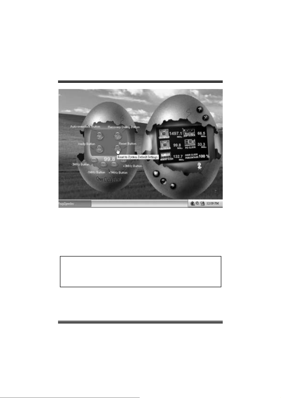
Overclock Panel contains these features:
a. “–3MHz button”, “-1MHz but ton”, “+1MHz butt on”, and “+3MHz button”: provide user
the a bility t o do real-t ime ov erc lock adjustment .
Warning: Manually overclock is potenti ally dangerous, especially w hen the
overclocking percentage is over 110 %. We strongl y recommend you verify
every speed you overclock by cli ck the Verify button. Or, you can just click
Auto overclock button and let [ WarpSpeeder™ ] automatically gets the best
result for you.
b. “R ecovery Dialog button”: Pop up t he following dialog. Let us er select a restoring
way if sy s tem need to do a f ail-safe reboot.
47
Page 51

c. “Auto-ov erclock button”: User can c lick this button and [ WarpSpeeder™ ] will set
the best and stable perform anc e and frequency automatic ally . [ W arpSpeeder™ ]
utility will exe c ute a s e ries of testin g until syst em fail. Then sys t em will do f ail-safe
reboot by us ing Watchdog f unct ion. Aft er reboot, the [ WarpSpeeder™ ] utility will
restore to the hardware default setting or load the verified best and stable
frequency a c cording to the Reco ver y Dialog’s setting.
d. “Verif y but ton”: User can c lick this button and [ WarpSpeeder™ ] will proceed a
testing for current frequenc y. If the testing is ok, then the current f requency will be
sav ed into system registry . If the testing f ail, sys tem will do a f ail-safe rebooting.
After reboot, the [ WarpSpeeder™ ] utility will restore to the hardware default
setting or load the verif ied best and stable frequency according to the Recovery
Dialog’ s se tting.
Note: Because th e testing p rog rams, i n voked in A u to-o ve rcl ock and Verify,
include DirectD raw, Direc t3D and Dir ect Show tes ts, the DirectX 8. 1 or newer
runtime library is requi red. And please make sure your di splay card’s color
depth is High color (16 bit) or True color( 24/32 bit ) that is required for
Direct3D rendering.
48
Page 52

5. H ardware Monit or Panel
Click t he Hardware Monit or button in Main Panel, t he button will be highlighted and the
Hardware Monitor panel will s lide out to lef t as the f ollowing f igure.
In t his panel, you c an get the real-time stat us inform ation of y our system. The inf ormat ion
will be refreshed ev ery 1 s econd.
6. About Panel
Click the About button in Main Panel, the butt on will be highlighted and t he About Panel
will slide out t o up as the following figure.
In t his panel, you c an get model name and detail inf ormation in hints of all the c hipset t hat
are related to overclocking. You can also get the mainboard’s BIOS model and the
Version number of [ WarpSpeeder™ ] utility.
49
Page 53

Note: Because the overclock, overvol tage, and hardware monitor features
are controlled by several separate chipset, [ WarpSpeeder™ ] di vi de these
features to separate panels. If one chipset is not on board, the correlative
button in Main panel will be disabled, but will not interfere other panel s’
functions. Thi s property can make [ WarpSpeeder™ ] utili ty more robust.
50
Page 54

Trouble Shoot ing
e
e
r
y
plugg
e
g up
y
pp
a
prog
e
r
PROBABLE SOLUTION
No power to the system at all Power light don’t
illuminate, fan inside power supply does not turn
on. Indicator light on keyboard does not turn on
PROBABLE SOLUTION
System inoperative. Keyboard lights are on,
power indicator lights are lit, hard drive is
sp in ning.
System does not boot from hard disk dri ve, can
be booted from CD-ROM drive.
System only boots from CD-ROM. Hard disk can
be read and applications can be used but
booting from hard disk is i mpossible.
PROBABLE SOLUTION
PROBABLE SOLUTION
* Make sure power cable is securely plugged i n
* Repl ac e c abl e
* Contac t techni cal s uppo rt
* Using even pressure on both ends of th
DIM M, press down firmly until the modul
snaps into p l ace.
* Check cable running from disk to dis k controlle
board. Make sure both ends are securel
ed in; check the drive type in th
standard CMOS setup.
* Backin
important. All hard disks are capable o
breaking down at any time.
* Back up data and applic ations files. Reforma
the hard drive. Re-install a
using backup dis ks.
the hard drive is extremel
l icat ions and dat
PROBABLE SOLUTION
Screen m essage says “Invalid Configuration” or
“CMOS Failure.”
PROBABLE SOLUTION
Cannot boot system after installing second hard
drive.
* Review system’s equipment . Make sure
c or r ect infor m a t io n is in s et u p.
* Set master/slave jum p e rs c o rrectly.
* Run SETUP
types. Call drive manufacturers fo
compatibility wi th other drives.
51
ram and select correct driv
Page 55

g
g
e
e
p
r
p
e
g
n
n
e
A
n
d
g
.
d
.
,
n
Problemlösung
MÖG LI CHE URSA CHE LÖSUNG
Das System hat keine Spannungsversorgung.
Die Stromanzei
Inneren der Stromversorgung wird nicht
eingeschaltet. Tastaturleuchten sind nic ht an.
Das System funktioniert nicht. Die
Tastaturleuchten sind an, die Stromanzeige
leuchtet, die Festplatte dreht sich.
Das System wird von der Festplatte nicht
hochgefahren, vom CD-ROM-Treiber aber ja.
Das System wird nur von der CD-ROM
hochgefahren. Die Festpl atte wird gelesen und
die Anwendungen sind funktionsfähig, aber es
ist nicht möglic h, das System von der Festplatte
zu starten.
Auf dem Bildschirm erscheint die Meldung
“Ungültige Konfiguration” oder “CMOS Fehler.”
Das System kann nach der Installation einer
zweiten Festplatte nicht hochgefahren werden.
e l euchtet nicht, der Lüfter im
MÖG LI CHE URSA CHE LÖSUNG
MÖG LI CHE URSA CHE LÖSUNG
MÖG LI CHE URSA CHE LÖSUNG
MÖG LI CHE URSA CHE LÖSUNG
MÖG LI CHE URSA CHE LÖSUNG
* Ve r sic h er n S ie si ch , d as s das Str o mk abe l ri ch ti
angebracht ist
* Ers etzen Sie das Stromkabel
* Wenden Sie sich an Ihre Kundendiensts telle
* Drück en Sie das DIMM-Modul bei gleichem
Druck an beide Seiten, bis es einrastet.
* Überprüfen Sie das Kabel zwischen Festplatt
und Festplatten-Controller. Versichern Si
sich, dass beide Enden richtig angebrach
sind; über
standardmäßigen CMOS-Einrichtung.
* Ein Backu
Festplatten können irgendwann beschädi
werden.
* Machen Sie eine Sicherungskopie von alle
Daten und Anwendungsdateien. Formatiere
Sie die Festplatte und reinstallieren Sie di
nwendungen und Daten mit Hilfe vo
Backup-Disks.
* Überprüfen Sie di e Systemkomponenten un
versichern Sie sich, das diese richti
ei ngerichtet si nd.
* Setzen Sie die Master/Slave-Jumper ric htig ein
* Führen Sie das SETUP-Programm aus un
wählen Sie die richtigen Laufwerktypen
Wenden Sie sic h an den Laufwerkhersteller
um die Kompatibilität mit anderen Laufwerke
zu überprüfen.
rüfen Sie den Laufwerktyp in de
der Fe stplatte ist se h r wichtig. All
52
Page 56

Dépannage
s
e
u
s
z
n
s
s
p
s
e
s
e
q
a
e
prog
z
e
PROBLÈME SOLUTION
Pas d'alimentation au système. Les voyants
lumineux ne s'allument pas, le ventilateur à
l'intérieur du bloc d'ali mentation ne s e met pas
en marche. Le voyant du clavier ne s'all ume pas
PROBLÈME SOLUTION
Le système ne fonctionne pas. Les voyants du
clavier sont allumés, les voyants de
l'alimentation auss i, le disque dur tourne.
Le système ne se réinitialise pas du disque dur,
réinitialisation possible depuis le lecteur
CD-ROM.
Le système ne se réinitialise que depuis le
CD-ROM. Le disque dur peut être lu et les
applications sont utilisables mais il est
impossible d'effectuer de réini tialisation depuis le
disque dur .
Un message s'affiche indiquant que la
configuration n'est pas valide ou qu'il y a une
panne du CM OS.
Impossible de réinitialiser le système après
l'installation d'un deuxième disque dur.
PROBLÈME SOLUTION
PROBLÈME SOLUTION
PROBLÈME SOLUTION
PROBLÈME SOLUTION
* Assurez-vous que le câble d'ali mentation es
bi en branché
* Remplacez le câble
* Contac tez le service d'assistance technique.
* En exerçant une pression uniforme sur le
deux extrémités du DIMM, poussez le modul
vers le bas jusqu'à ce qu'il s'enclenche.
* Vérifiez le câble du disque à la carte d
contrôleur de disque. Assurez-vous que le
deux extrémités sont bien branchées ; vérifie
le type de lecteur dans la configuratio
standard de CMOS.
* Il est très important d'effectuer de
sauvegardes du disque dur. Les disques dur
euvent tomber en panne à n'importe que
moment.
* Effectuez une sauvegarde des fichiers de
données et d'application. Reformatez l
di sque dur. Ré-installez les applications et le
données sauvegardées sur les disques d
secours.
* Vérifiez l'équipement du système
Assurez-vous
conf igurat ion sont corr ec t es.
* Réglez les cavaliers maître/esclav
correctement.
* Exécutez le
sélecti onnez les types de lec teur. Contac te
les fabricants pour toute question d
compatibilité avec les autres disques.
ue les informations de l
ramme SETUP e
53
Page 57

11/28/2003
54
Page 58

M7NCD BIOS Setup
BIOS Setup........................................................................................1
1 Main Menu.....................................................................................................3
2 Standard CMOS Features ..............................................................................6
3 Advanced BIOS Features...............................................................................9
4 Advanced Chipset Features..........................................................................12
5 Integrated Peripherals ..................................................................................16
6 Power Management Setup ........................................................................... 21
7 PnP /PCI Configurations...............................................................................24
8 PC Health Status ..........................................................................................26
i
Page 59

M7NCD BIOS Setup
BIOS Setup
Introduction
T his manua l disc ussed Award™ Setup p rogram bu ilt in to the ROM BIOS. T he Setup
program allows users to modify the basic system configuration. This special information is
th en st ored in ba tte ry-b acke d RAM so that it r etain s the Set up info rmatio n when the power
is turned off.
T he Award B IO S™ insta lled in you r com puter system’s RO M (R ead Only Me mory ) is a
custom version of an industry standard BIOS. This means that it supports AMD
input/output system. The BIOS provides critical low- level support for standard devices
such as disk drives and serial and parallel ports.
Addin g important has customized the Award BIOS™, but nonstandard, features such as
virus and password protection as well as special support for detailed fine-tuning of the
chipset controlling the entire system.
The rest of this manual is intended to guide you through the process of configuring your
system using Setup.
Plug and Play Support
These AWARD BIOS supports the Plug and Play Version 1.0A specification. ESCD
(Extended System Configuration Data) write is supported.
EPA Green PC Support
This AWARD BIOS supports Version 1.03 of the EP A Green PC specification.
APM Support
These AWARD BIOS supports Vers ion 1.1&1.2 of the Advanced P ower Management
(APM) specif ication. Power management features are implemented via the System
Management Interrupt (SMI). Sleep and Suspend power management modes are supported.
Power to the hard disk drives and video monitors can be managed by this AWARD BIOS.
®
processor
1
Page 60

M7NCD BIOS Setup
PCI Bus Suppo rt
This AW ARD BIOS also supports Version 2.1 of the Intel PCI (Peripheral Component
Interconnect) local bus specification.
DRAM Support
DDR SDRAM (Double Data Rate Synchronous DRAM) are supported.
Suppo rted CP Us
This AWARD BIOS supports the AMD
Us i ng Se t u p
In general, you use the arrow keys to highlight items, press <Enter> to select, use the
<PgUp> and <PgDn> keys to change entries, press <F1> for help and press <Esc> to quit.
The following table provides more detail about how to navigate in the Setup program by
using the keyboard.
Keystroke Function
Up arrow Move to p revio us item
Down arrow Move to next i tem
Left arro w Move to the item o n the left (men u bar)
Right arrow Move to the item on the right (menu bar)
Move Enter Move to the item you desired
PgUp key Increase the numeric value or make c hanges
PgDn key Decrease the numeric value or make changes
+ Key Increase the numeric value or make c hanges
- Key Decrease the numeric value or make changes
Esc key Main Menu – Quit and not save changes into CMOS
F1 k ey Ge nera l help o n S etup navig ation k eys
F5 key Load previous values from CMOS
F7 key Load the optimized defa ults
F10 key Save all the CMOS changes and exit
®
CPU.
Status Page Setup Me nu and Option Page Setup Menu – Exit
Current page and return to Main Menu
2
Page 61

M7NCD BIOS Setup
1 Main Menu
Once you enter Award BIOS™ CMOS Setup Utility, the Main Menu will appear on the
screen. The Main Menu allows you to select from several setup functions. Use the arrow
keys to select among the items and press <Enter> to accept and enter the sub-menu.
!! WARNING !!
The information about BIOS defaults on manual (Figu re
1,2,3,4,5,6,7,8,9) is just for reference, please refer to the BIOS
installed on board, for update information.
Figure 1. Main Menu
Standard CM OS Features
This submenu contains industry standard configurable options.
Advance d BIOS Features
This submenu allows you to configure enhanced features of the BIOS.
Advanced Chipset Features
3
Page 62

M7NCD BIOS Setup
This submenu allows you to configure special chipset features.
Integrated Pe ripherals
This submenu allows you to configure certain IDE hard drive options and Programmed
Input/ Output features.
Power Management Setup
This submenu allows you to configure the power management features.
PnP/PCI Configurations
This submenu allows you to configure certain “Plug and Play” and PCI options.
PC Health Status
This submenu allows you to monitor the hardware of your system.
Lo a d Op ti mize d De fa ul ts
This selection allows you to reload the BIOS when the system is having problems
particularly w ith the boot sequence. These configurations are factory settings optim ized
for this system. A confirmation message will be displayed before defaults are set.
Set Supervisor Password
Setting the supervisor password will prohibit everyone except the supervisor from making
changes using the CMOS Setup Utility. You will be prompted with to enter a password.
Set User Password
If the Supervisor P assword is not set, then the User Password will function in the same way
as the Supe rvisor P asswor d. If th e Supervis or Pas swor d is set and the User Pa ssword is
set, the “User” will only be able to view configurations but will not be able to change them.
4
Page 63

M7NCD BIOS Setup
Save & Exit Setup
Save all configuration changes to CMOS(memory) and exit setup. Confirmation message
will be displayed before proceeding.
Exit Without Saving
Abandon all changes made during the current session and exit setup. confirmation
message will be displayed before proceedin g.
Upgrade BIOS
This submenu allows you to upgrade bios.
5
Page 64

M7NCD BIOS Setup
2 Standard CMOS Features
The items in Standard CMOS Setup Menu are divided into 10 categories. Each category
includes no, one or more than one setup items. Use the arrow keys to highlight the item and
then use the<PgUp> or <PgDn> keys to select the value you want in each item.
Figure 2. Standard CM OS Setup
6
Page 65

M7NCD BIOS Setup
Main Menu Selec tions
This table shows the selections that you can make on the Main Menu.
Item Options Description
Date mm : dd : yy Set the system date. Note
Time hh : mm : ss Set the system internal
IDE Primary Master Options are in its sub
menu.
IDE Primary Slave Options are in its sub
menu.
IDE Secondary Master Options are in its su b
menu.
IDE Secondary Slave Options are in its su b
menu.
Drive A
Drive B
Video EGA/VGA
360K, 5.25 in
1.2M, 5.25 in
720K, 3.5 in
1.44M, 3.5 in
2.88M, 3.5 in
None
CGA 40
CGA 80
MONO
that the ‘Day’ automatically
changes when you set the
date.
clock.
Press <Enter> to enter the
sub menu of detailed
options
Press <Enter> to enter the
sub menu of detailed
options.
Press <Enter> to enter the
sub menu of detailed
options.
Press <Enter> to enter the
sub menu of detailed
options.
Selec t the type of floppy
disk drive installed in your
system.
Select the default video
device.
7
Page 66

M7NCD BIOS Setup
Item Options Description
Halt On All Errors
No Errors
All, but Keyboard
All, but Diskette
All, but Disk/ Key
Base Memory N/A Displays the amount of
Extended Memory N/A Displays the amount of
Total Memory N/A Displays the total memory
Select the situation in which
you want th e BIOS to st op
the POST process and
notify you.
conventional memory
detected during boot up.
extended memory detected
during boot up.
available in the system.
8
Page 67

M7NCD BIOS Setup
3 Advanced BIOS Features
Figure 3. Adva nce d BIOS Se tup
Boot Seq & Floppy Setup
First/ Second/ Third/ Boo t Other Device
These BIOS attempt to load the operating system from the device in the sequence
selected in these items.
The Choices: Floppy, LS120, HDD-0, SCSI, CDROM, HDD-1, HDD-2, HDD-3,
ZIP100, USB-FDD, USB-ZIP, USB-CDROM, USB-HDD, LAN, HPT370,
Disab led, Enabled.
Swap Floppy Drive
For systems with two floppy drives, this option allows you to swap logical drive
assignments.
The Choices: Disabled (default), Enabled.
Boot Up Floppy Seek
Enabling th is option will test the floppy drives to determine if they have 40 or 80
tracks. Disablin g this option reduces the time it takes to boot-up.
The Choices: Enabled, Disabled (default).
9
Page 68

M7NCD BIOS Setup
Cache Setup
External Cache
This option you to enable or disable “Level 2” secondary cache on the CPU,
which may improve performance.
The Choices:
Enabled (default) Enable cache.
Disab led Disable cache.
Virus Warning
T his op tion allows yo u to choo se th e Viru s Warnin g feature that is used to protect the I DE
Hard Disk boot sector. If this function is enabled and an attempt is made to write to the
boot sector, BIOS will display a warning message on the screen and sound an alarm beep.
Disabled (default) Virus protection is disabled.
Enabled Virus protection is activated.
Quick Power On Self Test
Enabling this option will cause an abridged version of the Power On Self-Test (POST) to
execute after you power up the computer.
Enabled (default) Enable quick POST.
Disabled Normal POST.
Boot Up NumLock Status
Selects the NumLock. State after power on.
On (default) Numpad is number keys.
Off Numpad is arrow keys.
Gate A20 Option
Select if chipset or keyboard controller should control Gate A20.
Normal A pin in the keyboard controller
Fast (default) Lets chipset control Gate A20.
Typematic Rate Setting
When a key is held down, the keystroke will repeat at a rate determined by the keyboard
controller. When enabled, the typematic rate and typematic delay can be configured.
The Choices: Disabled (default), Enabled.
Typematic Rate (Chars/Sec)
Sets the rate at which a keystroke is repeated when you hold the key down.
The Choices: 6 (default), 8,10,12,15,20,24,30.
Typematic Delay (Msec)
Sets the delay time after the key is held down before it begins to repeat the keystroke.
controls Gate A20.
10
Page 69

M7NCD BIOS Setup
The Choices: 250 (default), 500,750,1000.
Securi ty Optio n
This option will enable only individuals w ith passwords to br ing the system online and/or
to use the CMOS Setup Utility.
System A password is required for the system to boot and is
Setup (default) A password is required to access the Setup Utility
This will only apply if passwords are set from the Setup main menu.
APIC Mode
By selecting Enabled enables ACPI device mode reporting from the BIOS to the operating
system.
The Choices: Enabled (default), Disabled.
MPS Vers ion Co ntrol For OS
The BIOS supports version 1.1 and 1.4 of the Intel multiprocessor specif ication.
Select version supported by the operation system running on this computer.
The Choices: 1.4 (default), 1.1.
OS Select For DRAM > 64MB
A choice other than Non-OS2 is only used for OS2 systems with memory exceeding 64MB.
The Choices: Non-OS2 (default), OS2.
Video BIOS Shadow
Determines whether video BIOS will be copied to RAM for faster execution.
The Choices:
Enabled (default) Optional ROM is enabled.
Disabled Optional ROM is disabled.
Summary Screen Show
This item allows you to enable/ disable display the Summary Screen Show.
The Choices: Disabled (default), Enabled.
also required to access the Setup Utility.
only.
11
Page 70

M7NCD BIOS Setup
4 Advanced Chipset Features
This submenu allows you to configure the specific features of the chipset installed on your
system. This chipset manage bus speeds and access to system memory resources, such as
DRAM. It also coordinates communications with the P CI bus. The default settings that came
with your system have been optimized and therefore should not be changed unless you are
suspicious that the settings have been changed incorrectly.
Fig ure 4. Adva nce d Chipse t Setup
System Performance
Optimal (Default)
T his ite m allo ws you t o use the most stab le set tings .
Expert
This item allows full customizat ion of performance. Only for advanced users.
Turbo
This item allows you to use over clocked settings for higher performance but
with h igher risk of inestability.
FSB Frequenc y
This item allows you to select the FSB Frequency.
The Cho ices: 100MHz (Default ).
12
Page 71

M7NCD BIOS Setup
CPU Interface
Optimal (Default)
T his ite m allows you t o use the most stab le CP U / FSB par ameters .
Ag gress ive
This item allows you to use overclocked CPU/ FSB parameters.
Memory Freq uenc y
Select “Auto” for best performance.
Memo ry T i mi n gs
T(RAS)
This item allows you to set System Performance to “Optimal” to use the delay
recommended by the DIMM’s manufacturer.
T(RCD)
This item allows you to set System Performance to “Optimal” to use the delay
recommended by the DIMM’s manufacturer.
T (RP)
This item allows you to set System Performance to “Optimal” to use the delay
recommended by the DIMM’s manufacturer.
CAS Latency
This item allows you to set System Performance to “Optimal” to use the delay
recommended by the DIMM’s manufacturer.
The Cho ices: By SPD (Default), 50%, 60%, 66%, 75%, 80%, 83%, 100%, 120%,
125%, 133%, 150%, 166%, 200%, Auto.
Optimal (Default)
T his ite m allo ws you t o use the most stab le set tings .
Expert
This item allows you to enter timings manually.
Turbo
The Cho ices: 7 (Default), 1, 2, 3, 4, 5, 6, 8, 9, 10, 11, 12, 13, 14, 15.
The Cho ices: 1 (Default), 2, 3, 4, 5, 6, 7.
The Cho ices: 1 (Default), 2, 3, 4, 5, 6, 7.
The Cho ices: 2.5 (Default), 2.0, 3.0.
13
Page 72

M7NCD BIOS Setup
FSB Spread Spectrum
This item allows you to select the FSB Spread Spectrum.
The Cho ices: 0.50% (Defa ult).
AGP Spread Spectrum
This item allows you to select the AGP Spread Spectrum.
The Cho ices: 0.5% (Default).
AGP Ape rture Size (MB)
Select the size of the Accelerated Graphics Port (AGP) aperture. The apertures is a portion
of the PCI memory address range dedicated for graphics memory address space. Host
cycles that hit the aperture range are forwarded to the AGP without any translation.
The Choices: 64 (default), 4, 8, 16, 32, 128, 256.
AGP Frequency
This item allows you to select the AGP Frequency.
The Choices: Auto ( Defa ult) , 50MHz, 66M Hz, 67MHz, 68M Hz, 69MHz,
70MHz, 71MHz, 72MHz, 73MHz, 74MHz, 75MHz, 76MHz, 77MHz, 78MHz,
79MHz, 80MHz, 81MHz, 82MHz, 83MHz, 84MHz, 85MHz, 86MHz, 87MHz,
90MHz, 93MHz, 95MHz, 97MHz, 100MHz.
AGP 8X Support
This item allows you to enable or disable AGP 8X Support.
The Cho ices: Enabled (Default), Disabled.
AGP Fast Write Capability
T his ite m allows you En abled or Disab led AGP Fast Wr ite Cap abil ity.
The Cho ices: Enabled (Default), Disabled.
CPU Thermal Throttling
T his ite m allows you to select the CPU The rmal Thr ottlin g.
The Choices: 50% (Default), Disabled, 87.5%, 75%, 62.5%, 37.5%, 25%,
12.5%.
System BIOS Cacheable
Selecting Enabled allows you caching of the system BIOS ROM at F0000h~FFFFFh,
resulting a better system performance. However, if any program writes to this memory area,
a system error may result.
The Cho ices: Ena bled, Disabled (default).
14
Page 73

M7NCD BIOS Setup
Video RAM Cacheable
Enabling this option allows caching of the video R AM, resulting a better system
performance. However, if any program writes to this memory area, a system error may
re sult.
The Choices: Disabled (default), Enabled.
15
Page 74

M7NCD BIOS Setup
5 Integrated Peripherals
Figure 5. Integrated Peripherals
IDE F unc tion Setup
The chipset contains a PCI IDE interface with support for two IDE channels.
Select “Enabled” to activate the first and / or second IDE interface. If you install a primary
and / or secondary add-in IDE interface, select “Disabled” to deactivate an interface. If you
hi gh li ght th e lite ra l “P r ess E nter” next t o the “Onchip IDE Con trol” labe l and the n pre ss th e
enter key, it will take you a submenu with the following options:
OnChip IDE Channel 0/1
The motherboard chipset contains a PCI IDE interface with support for
two IDE channels. Select “Enabled” to activate the first and/or second IDE
interface. Select “Disabled” to deactivate an interface if you are going to install a
primary and/or secondary add-in IDE interface.
The Choices: Enabled (default), Disabled.
Prima ry / Secondary Master / Slave PIO
The IDE PIO (Programmed Input / Output) fields let you set a PIO mode (0-4)
for each of the IDE devices that the onboard IDE interface supports. Modes 0
through 4 provides successively increased performance. In Auto mode, the
system automatically determines the best mode for each device.
The Choices: Auto (default), Mode0, Mode1, Mode2, Mode3, Mode4.
16
Page 75

IDE Primary / Secondary Master / Slave UDMA
Ultra DMA/100 functiona lity can be implemented if it is supported by the IDE
hard drives in your system. As well, your operating environment requires a DMA
driver (Windows 95 OSR2 or a third party IDE bus master driver). If your hard
drive and your system software both support Ultra DMA/100, select Auto to
enable BIOS support.
The Choices: Auto (default), Disabled.
IDE Prefetch Mode
The “onboard” IDE drive interfaces supports IDE prefetching for faster drive
access. If the interface does not support prefetching. If you install a primary
and/or secondary add-in IDE interface, set this option to “Disabled”.
The Choices: Enabled (default), Disabled.
IDE HDD Block Mode
Blo ck mode is a ls o called b loc k tra nsf er, multip le co mm ands , or multip le se ctor
read / write. If your IDE hard drive supports block mode (most new drives do),
select Enabled for automatic detection of the optimal number of block mode
(most new drives do), select Enabled for automatic detection of the optimal
number of block read / write per sector where the drive can support.
The Choices: Enabled (default), Disabled.
Onboa rd De vice
AC97 Audio
This item allows you to decide to enable/ disable to support AC97 Audio.
The Choices: Auto (default), Disabled.
MC97 Modem
This item allows you to decide to enable/ disable to support AC97 Modem.
The Choices: Auto (default), Disabled.
MAC LAN (nVIDIA)
T his ite m allows you t o select MAC LAN.
The Choices: Auto (Default), Disabled.
Ma chin e MAC (NV ) Addre ss
This item allows you to enable or disable Machine MAC Address.
The Choices: Disabled (Default), Enabled.
MAC (NV) Address Input
Onchip 1394 Chip
This item allows you to set the Onchip 1394 Chip.
The Choices: Auto (Default), Disabled.
M7NCD BIOS Setup
17
Page 76

M7NCD BIOS Setup
Init Display First
This item allows you to decide to active whether PCI Slot or on-chip VGA first.
The Choices: Onboard/AGP, PCI Slot (default).
OnChip USB
T his ite m allows you t o set the o nch ip USB.
The Choices: V1.1+V2.0 (default), Disabled, V1.1.
USB Keyboard Suppo rt
T he default value is D isabled .
Enabled Enable USB Keyboard Support.
Disabled (default) Disable USB Keyboard Support.
Onboa rd I/O Chi p Se tup
Power On Function
This item allows you to choose the powen on function.
The Choices: Button Only (default), Password, Hot Key, Mouse Left, Mouse
Right, Any Key, Keyboard 98.
KB Po wer o n Pas swo rd
Input password and press Enter to set the Keyboard power on password .
HOT Key power ON
Input password and press Enter to set the Keyboard power on password .
The Choices: Ctrl-F1(default) , Ctrl-F2 , Ctrl-F3 , Ctrl-F4 , Ctrl-F5,
Ctrl-F6 , Ctrl-F7 , Ctrl-F8 , Ctrl-F9, Ctrl-F10 , Ctrl-F11 , Ctrl-F12 .
On bo ard FDC Co ntro ller
Select Enabled if your system has a floppy disk controller (FDC) installed on the
system board and you wish to use it. If install and FDC or the system has no
floppy drive, select Disab led in this field.
The Choices: Enabled (default), Disabled.
On bo a rd Serial P ort 1
Select an address and corresponding interrupt for the first and second serial ports.
The Cho ices: 3F8/IRQ4 (default), Disabled, Auto, 2F8/IRQ3,
3E8/IRQ4, 2E8/IRQ3.
On bo a rd Serial P ort2
Select an address and corresponding interrupt for the first and second serial ports.
The Choices: Disabled, 3F8/IRQ4, 2F8/IRQ3 (default), 3E8/IRQ4, 2E8/IRQ3,
Auto.
18
Page 77

M7NCD BIOS Setup
UART Mode Select
This item allows you to determine which Infra Red (IR) function of onboard I/O
chip.
The Choices: No rmal (default), ASKIR, IrDA.
RxD, TxD Active
This item allows you to determine which Infrared (IR) function of onboard I/O
chip.
The Choices: Hi / Lo (default), Hi / Hi, Lo / Hi, Lo / Lo.
IR Transm issio n Dela y
T his ite m allows you t o enab le/dis ab le IR tr ansm iss ion d e lay .
The Choices: Enabled (default), Disabled.
UR2 Duplex Mo de
Select the value requ ired by the IR device connected to the IR port. Full-duplex
mo de permits simultaneous t wo-d irection t ransmission. H alf- duple x mode
permits transmission in one direction only at a time.
The Choices: Half ( def ault) , Full.
Use IR Pins
Consult your IR peripheral documentation to select the correct setting of the TxD
and RxD signals.
The Choices: IR-Rx2Tx2 (default), RxD2, TxD2.
Onboard Parallel Port
This item allows you to determine access onboard parallel port controller with
which I/O address.
The Choices: 378/IRQ7 (default), 278/IRQ5, 3BC/IRQ7, Disabled.
Parallel Port Mode
The default value is SPP.
SPP (default) Usin g Parallel port as Standard Printer P ort.
EP P Usin g P aralle l por t as E nhanc ed Paralle l
Port.
EC P Us in g P aralle l port as Ext ended C apabilit ies
Port
EC P+EPP Usin g Pa ralle l po rt a s ECP & EPP mode.
EPP Mode Select
Select EPP port type 1.7 or 1.9.
The Choices: EPP 1.7(default), EPP1.9.
ECP Mode Use DMA
Select a DMA Channel for the port.
The Choices: 3 (default), 1.
19
Page 78

M7NCD BIOS Setup
Game Port Address
Game Port I/O Address.
The Choices: 201 (default), 209, Disabled.
Midi Port Address
Midi P ort Base I/O Address.
The Choices: 330 (default), 300, 290, Disabled.
Midi Port IRQ
This determines the IRQ in which the Midi Port can use.
The Choices: 10 (default), 5
20
Page 79

M7NCD BIOS Setup
6 Power Management Setup
The Power Management Setup Menu allows you to configure your system to utilize energy
conservation and power up/power down features.
Figure 6. Power Manageme nt Setup
ACP I f unctio n
This item displays the status of the Advanced Configuration and Power Management
(ACPI).
The Choices: Enabled (default), Disabled.
ACP I Sus pe nd Ty pe
The item allows you to select the suspend type under the ACPI operating system.
The Choices: S1 (POS) (default) Power on Suspend
S3 (STR) Suspend to RAM
S1 & S3 POS+ST R
Power Management
This category allows you to select the type (or degree) of power saving and is directly
related to the followin g modes:
1.HDD Power Down.
2. Susp end M ode.
21
Page 80

M7NCD BIOS Setup
There are four options of Power Management, three of which have fixed mode settings
Min. Power Saving
Minimum power management.
Su spend Mode = 1 hr.
HDD Power Down = 15 min
Max. Power Saving
Maximum power management only available for sl CPU’s.
Su spend Mode = 1 min.
HDD Power Down = 1 min.
User De f i ne d (default)
Allows you to set each mode individually.
When not disabled, each of the ranges are from 1 min. to 1 hr. except for HDD
Power Down which ranges from 1 min. to 15 min. and disable.
Video Off Method
T his op tion de term ines the mann er in whic h the mo nitor is goes blank.
V/H SYNC+Blank
This selection w ill cause the system to turn off the vertical and horizontal
synchronization ports and write blanks to the video buffer.
Blank Screen
This option only writes blanks to the video buffer.
DPM S Support (default)
Initia l disp lay p ower mana gement signa lin g.
HDD Power Down
When enabled, the hard disk drive will power down and after a set time of system inactivity.
Al l othe r device s re main act ive.
The Cho ices: Disabled (default), 1 Min, 2 Min, 3 Min, 4 Min, 5 Min, 6 Min, 7 Min,8 Min,
9 Min, 10 Min, 11 Min, 12 Min, 13 Min, 14 Min, 15Min.
Soft-Off by PBTN
Pressing the power button for more than 4 seconds forces the system to enter the
Soft-Off state when the system has “hung.”
The Cho ices: Delay 4 Sec, Instant-Off (default).
22
Page 81

M7NCD BIOS Setup
WOL (PME#) Fro m Soft-Off
This item allows you to enable or disable the WOL (PME#) From Soft-Off.
The Cho ices: Disabled (Default), Enabled.
WOR (RI#) From Soft-Off
This item allows you to enable or disable the WOR (RI#) From Soft-Off.
The Cho ices: Disabled (Default), Enabled.
USB Resume from S3/S4
This item allows you to enable or disable S3 Resume by USB (Win98).
The Cho ices: Disabled (Default), Enabled.
Power-On by Alarm
This item allows you to enable or disabled power on by alarm.
The Cho ices: Disabled (Default), Enabled.
PWRON After PWR-Fail
This field determines the action the system will automatically take when power is restored
to a system that had lost power previously without any subsequent manual intervention.
There are 3 sources that provide current to the CMOS area that retains these Power-On
instructions; the motherboard battery (3V), the Power Supply (5VSB), and the P ower
Supply (3.3V). While AC is not supplying power, the motherboard uses the motherboard
battery (3V). If AC power is supplied and the Power Supply is not turned on, 5VSB from
the Power Supply is used. When the Power Supply is eventually turned on 3.3V from the
Power Supply will be used.
There are 3 options: “Former-Sts”, “On”, “Off”.
“Former-Sts” Means to maintain the last status of the CMOS when AC
po wer is lost.
“On” Means always set CMOS to the “On” status when AC
po wer is lost
“Off” (default) Means always set CMOS to the “Off” status when AC
For example: If set to “Former-Sts” and AC power is lost when system is live, then after
AC power is restored, the system will automatically power on. If AC power is lost when
system is not live, system will remain powered off.
po wer is lost.
23
Page 82

M7NCD BIOS Setup
7 PnP/PCI Configurations
This section describes configuring the PCI bus system. PCI, or Personal Computer
Interconnect, is a system which allows I/O devices to operate at speeds nearing the speed of
the CPU itself uses when commun icating with its own special components. This section
covers some very technical items and it is strongly recommended that only experienced
users should make any changes to the default settin gs.
Figure 7. P nP/PCI Configurations
Reset Configuration Data
The system BIOS supports the PnP feature which requires the system to record which
resources are assigned and protects resources from conflict. Every peripheral device has a
node, which is called ESCD. This node records which resources are assigned to it. The
system nee ds to record and u pdate ES CD to the mem ory lo cations. These locat ions (4K)
are reserved in the system BIOS. If the Disabled (default) option is chosen, the system‘s
ESCD will update only when the new configuration varies from the last one. If the Enabled
option is chosen, the system is forced to update ESCDs and then is automatically set to the
“D isab led” mode.
The above settings will be shown on the screen only if “Manual” is chosen for the resources
controlled by function.
Le gacy is the term, which s ignifies that a resource is as signed to the ISA Bus an d prov ides
24
Page 83

M7NCD BIOS Setup
non-PnP ISA add-on cards. PCI / ISA PnP signifies that a resource is assigned to the PCI
Bus or provides for ISA PnP add-on cards and peripherals.
The Choices: Disabled (default), Enabled.
Resources Controlled By
By Choosing “Auto(ESCD)” (default), the system BIOS will detect the system resources
and automatically assign the relative IRQ and DMA channel for each peripheral.By
Choosing “Manual”, the user will need to assign IRQ & DMA for add-on cards. Be sure
that there are no IRQ/DMA and I/O port conflicts.
IRQ Resources
This submenu will allow you to assign each system interrupt a type, depending on the type
of device using the interrupt. When you press the “Press Enter” tag, you will be directed to
a submenu that will allow you to configure the system interrupts. This is only
configurable when “Resources Controlled By” is set to “Manual”.
IRQ-3 assigned to PCI Device
IRQ-4 assigned to PCI Device
IRQ-5 assigned to PCI Device
IRQ-7 assigned to PCI Device
IRQ-9 assigned to PCI Device
IRQ-10 assigned to PCI Device
IRQ-11 assigned to PCI Device
IRQ-12 assigned to PCI Device
IRQ-14 assigned to PCI Device
IRQ-15 assigned to PCI Device
PCI / VG A Pa lette Sn oop
Choose Disabled or Enabled. Some graphic contro llers which are not VGA compatible
take the output from a VGA controller and map it to their display as a way to provide boot
information and VGA compatibility.
However, the color information comin g from the VGA co ntro l ler is draw n from the palette
table inside the VGA controller to generate the proper colors, and the graphic controller
needs to know what is in the palette of th e VGA contro ller. T o do this, the non-VGA
graphic controller watches for the Write access to the VGA palette and registers the snoop
data. In PCI based systems, where the VGA controller is on the PCI bus and a non-VGA
graphic controller is on an IS A bus, the Write Access to the palette will not show up on the
ISA bus if the PCI VGA controller responds to the Write.
In this case, the PCI VGA controller shou ld not respond to the Write, it should only sno op
the data and permit the access to be forwarded to the ISA bus. The non-VGA ISA graphic
controller can then snoop the data on the ISA bus. Unless you have the above situation,
you should disable this option.
Disabled (default) Disables the function.
Enabled Enables the function.
25
Page 84

M7NCD BIOS Setup
8 PC Health Status
Figure 8. PC Health Sta tus
Current CPU Temperature
Show you the current CPU temperature.
Current SYSFAN Speed
This field displays the current SYSFAN speed.
Current CPUFAN Speed
This field displays the current CPUFAN speed.
CP U Vco re / AGP Vco re/ +3.3 V / +12 V/ -12V/ -5V
Detect the system’s voltage status automatically.
Show H/W Monitor in POST
If you computer contain a monitoring system, it will show PC health status during POST stage.
The item offers several delay time to select you want.
The C hoices: Enable d (default), Disabled.
26
Page 85

M7NCD BIOS Setup
Chassis Open Warning
This item allows you to enable or disable Chassis Open Warnin g beep.
The Cho ices: Disabled (Default), Enabled.
27
 Loading...