


M6VLA
Federal Communications Commission
(F.C.C) Statement
This device complies with Part 15 of the FCC Rules. Operation of this
device is subject to the following two conditions: (1) this device may not;
cause harmful interference, and (2) this device must accept any
interference received, including interference that may cause undesired
operation.
Accessories: This device has been tested and found to comply with the
limits of a Class B digital device, the accessories associated with this
equipment are as follows:
1. Shielded serial cable. (Can be obtained from multiple retail outlets)
2. Shielded printer cable. (Can be obtained from multiple retail outlets)
3. Shielded video cable. (Can be obtained from multiple retail outlets)
4. Shielded power cord. (Provide d by manufacturer)
These accessories are required to be used in order to ensure compliance
with FCC Rules. It is the responsibility of the user to provide and use
these accessories properly.
This equipm ent has be en test ed and foun d to compl y with the l imits of
a Class B digital device, pursuant to Part 15 of the FCC Rules. These
limits are designed to provide reasonable protection against harmful
interfere nce in a residential install ation. This equipment gene rates, uses
and can radiate radio frequency energy and, if not installed and used in
accordance with the instructions, may cause harmful interference to radio
communications. However, there is no guarantee that interference will not
occur in a particular installation. If this equipment does cause harmful
interference to radio or television reception, which can be determined by
turning the equipment off and on, the us er is encouraged to try to correct
the interference by one or more of the following measu res:
1. Reorient / Relocate the receiving antenna.
2. Increase the separation between the equipm ent and receiver.
3. Connect the equipment into an outlet on a circuit different from that
to which the receiver is connected.

M6VLA
4. Consult the dealer or an experienced radio/TV technician for help.
Caution: Changes or modifications not expressly approved by the
manufacturer could void the user’s authority to operate the equipment.
Disclaimer
The Vendor makes no representations or warranties with respect to the
contents here of and specially disclaims any implied warranties of
merchantability or fitness for any purpose. Further the Vendor reserves
the right to revise this publication and to make changes from time to time
in the contents here of without obligation to notify any party beforehand.
Duplication of this publication, in part or in whole, is not allowed without
first obtaining the Vendor’s approval in writing.
Trademarks and Remarks
MS-DOS, Windows, Windows NT, and Windows 9x,Windows ME
and Windows 2000 are products of Microsoft Corp, with its ownership of
trademark, and are distributed by the Vendor under a license agreement.
All trademarks used in this manual are the property of their respective
owners.
Copyright(C) 2001
All Rights Reserved
Canadian D.O.C. Statement
This digital apparatus does not exceed the Class B limits for radio noise
emissions from digital apparatus as set out in the radio interference
regulations of the Canadian Department of Communications.
Cet appareil numbérique n’emet pas de bruits radioélectriques
dépassant les limites appliqués aux appareils numbériques de Class B
préscrits dans le reglement du brouillage radioélectrique edict par le
ministere Des Communications du Canada.

Contents
i
Introduction ................................................................................1-1
1. Motherboard Description ............................................ ..........1-2
1.1 Features...................................................................................................1-2
1.1.1 Hardware.........................................................................................1-2
1.1.2 Software ..........................................................................................1-6
1.1.3 Attachments.....................................................................................1-6
1.2 Motherboard Installation.........................................................................1-7
1.2.1 Layout of Motherboard ...................................................................1-7
1.3 Motherboard Connectors.........................................................................1-8
1.3.1 Front Panel Connectors (JPANEL1) ...............................................1-9
1.3.2 Hard Disk Connectors (IDE1/ IDE2) ............................................1-11
1.3.3 Floppy Disk Connector (FDD1)....................................................1-11
1.3.4 ATX Power C onnector (JATXPWR1)..........................................1-12
1.3.5 AT Power Connector (JATPWR1)................................................1-12
1.4 Serial and Parallel Interface Ports................... .. ... .. .. ................ .. ...........1-13
1.5 CPU Installation/Jumper Setting...........................................................1-19
1.5.1 CPU Installation Procedure...........................................................1-19
1.6 Jumper Settings.....................................................................................1-20
1.6.1 CMOS Function Selection: JCMOS1............................................1-21
1.6.2 Wake-On-LAN Header: JWOL1 (Optional).................................1-21
1.6.3 CPU Fan Power Connector: JCFAN1 ...........................................1-22
1.6.4 System Fan Power Connector: JSFAN1 (Optional)......................1-22

Contents
ii
1.6.5 USB Connector: JUSB1&JUSB2(Optional).................................1-22
1.7 DRAM Installation................................................................................1-23
1.7.1 DIMM ...........................................................................................1-23
1.7.2 How to install a DIMM Module....................................................1-24
1.8 Audio Subsystem ..................................................................................1-25
1.8.1 CD Audio- In Connector: JCD IN1 / JCDIN2................................1-26
1.8.2 Telephony Connector: JTAD1(Optional)......................................1-26
2. BIOS Setup........... .................. ... ..............................................2-1
2.1 Main Menu..............................................................................................2-3
2.2 Standard CMOS Features........................................................................2-6
2.3 Advanced BIOS Features........................................................................2-9
2.4 Advanced Chipset Features....... .. .. ................ ............................. ...........2-14
2.5 Integrated Peripherals ...........................................................................2-17
2.6 Power Management Setup ....................................................................2-22
2.7 PNP / PCI Configuration Setup.............................................................2-26
2.8 PC Health Status ...................................................................................2-30
2.9 Frequency Control.................................................................................2-31
3. Software Setup........................................................ ... .............3-1
3.1 Software List...........................................................................................3-1
3.2 Software Installation...............................................................................3-2
3.3 Using Software........................................................................................3-4
4. Trouble Shooting ....................................................................4-1

Chapter 1 Motherboard Description
1-1
Introduction
System Overview
Thanks for buying this product! This manual was written to help you start using
this product as qu ickly and smoothly as possible. Inside you wil l find adequate
explanations to solve most problems. In order for this reference material to be of
greatest use, refer to the “expanded table of contents” to find relevant topics.
This board in corporates t he syste m board, ISA I/O, a nd PCI B US, IDE i nterface
into one board that provides a total PC solution. The motherboard, a processor
based PC/Baby AT syst em, and ISA Bus, and PCI Local Bu s to su pport upgrades
to your system performance. It is ideal for multi-tasking and fully supports
MS-DOS, Windows ME, Windows NT, Windows 2000, Novell, OS/2,
Windows9x, UNIX, SCO UN IX etc . This manual also ex plain s how to install the
motherboard for operation, and how to setup your CMOS configuration with the
BIOS setup prog r a m .

Chapter 1 Motherboard Description
1-2
1. Motherboard Description
1.1 Features
1.1.1 Har d ware
CPU
− Supports the Celeron
TM
processor (PPGA) and the Pentium
®
!!!
Micro-Processor for high-end workstations and servers.
− CPU Socket 370.
− Runs at 66/100/133 Mhz Fro nt Side Bus fr equency.
DRAM Memo r y
− Supports two 8/16/32/64/128/256 MB DIM M module socket s.
− Supports Synchronous DRAM (3 .3V).
− Supports a ma ximum memory size of 512 MB with SDRAM.
− 133Mhz Bus frequency.
Internal Accelerated Graphics Port (AGP) Controller
− AGP v1.0 compliant.
− Pipelined spli t- tra ns a c tio n lo ng -bur s t tra ns fers up to 533 MB/se c.
− Eight lev e l r e ad re quest queue .
− Four level posted-write request queue.
− Thirty-two le vel (quadwords ) re a d da ta FI FO (128 by te s ).
− Sixteen level (qua dwords) write data FI FO( 64 bytes).
− Intelligent request reordering for maximum AGP bus utilization.
− Supports Flush /Fence commands.
− Graphics Address Relocation Table (GART).
− One level TLB structure.
− Sixteen entry fully associative page table.
− LRU replacement scheme.
− Independent GART lookup control for host /AGP /PCI master
accesses.
− Windows 95 OSR-2 VXD and integrated Windows 98 / NT5 miniport
driver support.

Chapter 1 Motherboard Description
1-3
Sophisticated Power Management Features
− Independent clock stop controls for CPU / SDRAM,Internal AGP and
PCI bus.
− PCI and AGP bus clock run and clo c k g e ne r a to r co nt ro l.
− Low-leakage I/O pa ds.
General Graphic Capabilities
− 64-bit Single Cycle 2D/3D Graphics Engine.
− Supports 2 to 8 Mbytes of Frame Buffer located in Sy stem Me mory.
− Real Time DVD MPEG-2 and AC-3 Playback.
− Video Processor.
− I
2
C Serial Interface.
− Integrated 24-bit 230MHz True Color DAC.
− Extended Scre e n Resolutions up to 1600x1200.
− Extended Text Mo des 80 or 132 columns by 25/30/ 43/60 ro ws .
− DirectX 6 and OpenGL I CD API .
High Performance rCADE3D™ Accelerator
− 32 entry command queue,32 entry data queue.
− 4Kbyte texture cache with over 90% hit rates.
− Pipelined Single Cycle Setup / Texturing /Rendering Engines.
− DirectDraw™ acceleration.
− Multiple buffering and page flipping.
Setup Engine
− 32-bit IEEE floating point input data.
− Slope and ve rtex calculat io ns.
− Back facing triangle culling.
− 1/16 sub-pixel posit ion ing.
Rendering Engine
− High performance single pass e xecution.
− Diffused and specula lighting.
− Gouraud and flat shading.
− Anti-aliasing including edge,scene,and super-sampling.
− OpenGL compliant blending for fog and depth-cueing.
− 16-bit Z-buffer.
− 8/16/32 bit per pi xel color forma ts.

Chapter 1 Motherboard Description
1-4
Texturing Engine
− 1/2/4/8-bits per pixel quality non-palletized textures.
− 16/32-bits per pixe l quali ty no n-pa ll e ti zed te xt ure s .
− Pallet formats in ARGB 565,1555,o r 444.
− Tri-linear,bi-linea r, a nd po int-s a m p le d fi lt e ri ng.
− Mip-mapping with multiple Level-Of-Detail (LOD) calculations and
prespective correction.
− Color keying for translucency.
2D GUI Engine
− 8/15/16/24/32-bits pe r pixel color formats.
− 256 Raster Operations (ROPs).
− Accelerated draw ing: B itBLTs ,lines,poly gons,fills ,patterns,cl ipping,bi t
masking.
− Panning,scrolling,clipping,color expansion,sprites.
− 32x32 and 64x64 Hardwa re Cursor.
− DOS graphics and text modes.
DVD
− Hardware-Assisted MPEG-2 Architecture for DVD with AC-3.
− Simultaneous motion compensation and front-end processing
(parsing, decryption a nd de co de).
− Supports full DVD 1 .0,VCD 2.0 and CD-Karaoke.
− Microsoft DirectShow 2.x native support,backward compatible to
MCI.
− No additional frame buffer requirements.
− Dynamic frame and field de-interlace filtering for high quality
playback on VGA monitors(Bob and Weave).
− Tamper-proof software CSS implementation.
− Freeze,Fast-Forward, Slow Motion, Reverse.
− Pan-and-Scan suppor t fo r 16:9 Sequence.
Super I/O Built-in onboard
− Support one mult i- m o de Pa ra llel Port.
(1) Standard & Bidirection Parallel Port (SPP).
(2) Enhanced Parallel Port (EPP).

Chapter 1 Motherboard Description
1-5
(3) Extended Capabilities Port (ECP).
− Supports one se ri al port , 16550 UART wit h 16 byte FI F O.
− UART data rates up to 1. 5 Mbaud.
− Supports one Inf r ared transm iss i o n (IR ) po r t.
− Supports PS/2 Mouse.
− Supports 360KB, 720KB, 1.2MB, 1.44MB and 2.88MB floppy disk
drives.
Direct Sound Ready AC97 Digital Audio Controller
− Dual full-dupl ex Direct Sound chan nels between system memo ry and
AC97 link.
− PCI master interface with scatter / gather and bursting capability.
− 32 byte FIFO of eac h direct sound channel.
− Host based sample rate co nverter and mixer.
− Standard v1.0 or v2.0 AC97 Codec in terface for single or cascaded
AC97 Codec's from multiple vendors.
− Loopback capability for r e-directing mixed audio streams into USB
and 1394 speakers.
− Hardware SoundBlaster Pro fo r Windows DOS box and real-mode Do s
legacy compatibility.
− Plug and play with 4 IRQ, 4 DMA, and 4 I/O space options for
SoundBlaster Pro and MIDI hardware.
− Hardware assisted FM synthesis for legacy compatibility.
− Direct two game ports and one MIDI port interface.
− Complete software driver support for Windows 95, Windows 98,
Windows NT, Windows 2000 and W indow s ME.
Dimensions (Baby AT form-factor)
− 21.82cm x 22cm (WxL)
Power Management
− Supports both ACPI (Advanced and Configuration and Power
Interface) and legacy (APM) power management.
− ACPI v1.0 Co m p lia nt.
− APM v1.2 Compliant.
− CPU clock throttl ing and clock st op control for compl ete ACPI C0 to
C3 state support .

Chapter 1 Motherboard Description
1-6
1.1.2 So ft ware
BIOS
− AWARD legal & user-frie ndly BIOS.
− Supports PnP functi ons.
Operating Systems
− Offers the highest performance for MS-DOS, OS/2, Windows NT,
Windows 2000, Windows 31 / 95 / 98, Windows ME, Novell, UNIX,
SCO UNIT, and others .
1.1.3 Attachments
− HDD Cable.
− FDD Cable.
− COM1 / Printer Ca ble .
− VGA Cable + PS2(Mouse ).
− AudioGame Port Cable.

Chapter 1 Motherboard Description
1-7
1.2 Motherboard Installation
1.2.1 Layout of Motherboard
Model No.M6VLA
CPU
Socket 370
CPU1
JCFAN1
JUSB1
JKB1
JCOM1
JATXPWR1
JATPWR1
JWOL1
JAUDJOY1
JPRNT1
JVGA1
U6
BAT1
JCMOS1
AMR1
JCDIN1
JCDIN2
JTAD1
PCI1
PCI2
PCI3
ISA1
U17
ROM1
JPANEL1
JSFAN1
IDE1 IDE2
FDD1
DIMM1
DIMM2
BIOS
FLOPPY DISK CONN.
SECONDARY IDE CONN.
PRIMARY IDE CONN.
PCI BUS SLOT
PCI BUS SLOT
PCI BUS SLOT
AMR SLOT
ISA SLOT
VT8601A
VT82C686A
/82C686B
JMS2
129
10
1
1
1
1
JUSB2
1
1
1
2
12
1
1

Chapter 1 Motherboard Description
1-8
1.3 Motherboard Connectors
A. USB Connector (JUSB1) M. PCI Bus Slot (PCI1-3)
B. Keyboard Connector (JKB1) N. ISA Bus Slot (ISA1)
C. Com Port (JCOM1) O. CMOS Function Selection (JCMOS1)
D. Mouse Connector (JMS2) P. Front Panel Connector (JPANEL1)
E. Wake On LAN (*JWOL1) Q. System Fan (*JSFAN1)
F. Game / Audio Port (JAU DJOY1) R. IDE Connector (IDE1-2)
G. Print Port (JPRNT1) S. Floppy Disk Connector (FDD1)
H. AMR Connector (AMR1) T. DIMMs (DIMM1-2 )
I. CD Audio-In Connector (JCDIN1) U. CPU Fan (JCFAN1)
J. CD Audio-In Connec tor (JCDIN 2) V. VGA Connector (JVGA1)
K. Telephony Connector (*JTAD1) W. AT Power Connector (JATPWR1)
L. USB Connector (*JUSB2) X. ATX Power Connector (JATX PWR1)
NOTE: The “ * “mark represent t he f unction is optional.
A
B
C
D
E
F
G
H
I
J
L
N
O
P
Q
R
S
T
U
V
K
WMX

Chapter 1 Motherboard Description
1-9
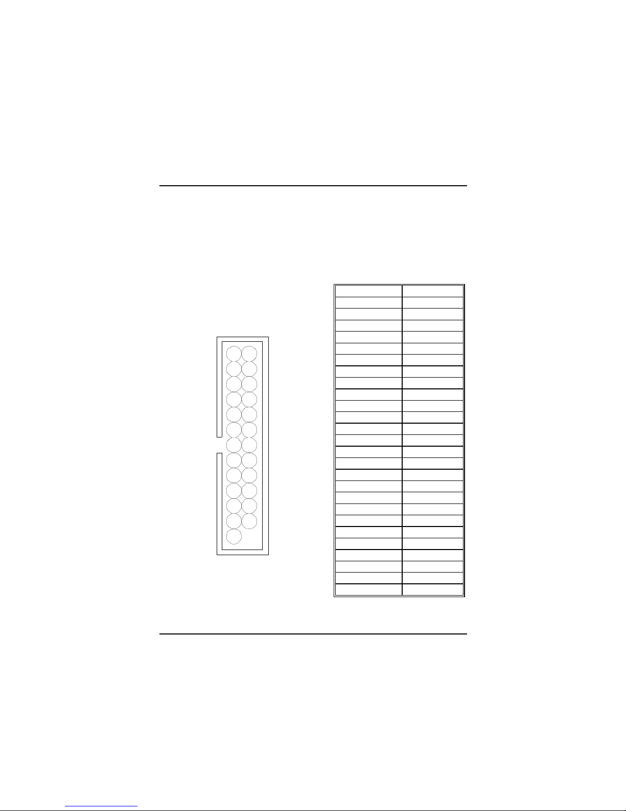
1.3.1 Front Panel Connectors (JPANEL1)
Pin
No.
Assignment Function
Pin
No.
Assignment Function
3
NC
4
Ground Ground
5
Ground
6
NC NC
7
+5V
Speaker
Connector
8
Power LED(+
)
9
HDD LED(+)
10
Power LED(+
)
11
HDD LED(-)
HDD Drive
LED
12
Power LED(-)
Power LED
13
Ground
14
Power Button
15
Reset Switch
Reset
Button
16
Ground
ATX Power
Button
17
VCC
18
Sleep Switch
19
IRRX
20
Ground
SLP
21
Ground
22
NC NC
23
IRTX
IrDA
Connector
24
+5V VCC
25
NC NC
26
NC NC
1
2
26
25
SPK
HLED RST IR NC
V G NC PWR-LED PWR SLP NC NCV

Chapter 1 Motherboard Description
1-10
Speaker Connector
An offboard speaker can be installed on the motherboard as a manufacturing
option. An offboard speaker can b e connected to the motherboard at the fron t
panel connector. The speaker (onboard or offboard) provides error beep code
information du ring the Power On Self-Test w hen the computer cannot use the
video interfac e. T he speaker is n o t connected to the audio sub s ystem and do es n ot
receive output from the audio subsystem.
Reset Button
This connector can be connected to a momentary SPST type switch that is
normally open. Wh en the switch is cl osed, the motherboard r esets and runs th e
POST.
Power LED Connector
This connector can b e conn ected to an L ED th at wil l fla shin g wh en the co mput er
is slee ping .
Hard Drive LED Connector
This connector can be c onn ect ed t o an LE D t o provi d e a visu al ind icator that data
is being read from or written to a hard drive. For the LED to function properly, an
IDE drive must be connected to the onboard hard drive controller.
Infrared Connector
After the IrDA interface is configured, files can be transferred from or to portable
devices such as laptops, PDAs, and printers using application software.
Green (Sleep/Resume) Switch
When APM is enabl ed in the system BIOS, and the operating system’s APM
driver is loaded, the system can enter sleep (standby) mode in one of the
following ways:
• Optiona l fro nt pane l SM I butto n
• Prolonged syst e m ina c t ivi ty us ing the BIOS inac t iv ity ti m e r feature
The 2-pin header located on the front panel I/O connector supports a front
panel SMI switch, which must be a momentary SPST type that is
normally open.
Closing th e SMI switch sends a System Manage ment Interrupt (SMI) to

Chapter 1 Motherboard Description
1-11
the processor, which immediately goes into System Management Mod e
(SMM).While the computer is in sleep mode it is fully capable of
respondin g to and servi cing ext ernal interr upts (su ch as an incomi ng fax)
even though the monitor turns on only if a keyboard or mouse interrupt
occurs. To reactivate or resume the system, the SMI switch must be
pressed again, or the keyboard or mouse must be used.
Power On Button (Use ATX Power)
This connector can be connect ed to a front pan el power swit ch. The switch must
pull the Power Button pin to ground for at least 50 ms to signal the power supply
to switch on or off. (The time requirement is due to internal debounce circuitry on
the motherboard.) At least two seconds must pass before the power supply will
recognize another on/off signal.
1.3.2 Hard Disk Connectors (IDE1/ IDE2)
The motherboard has a 32-bit Enhanced PCI IDE Controller that provides PIO
Mode 0~4, Bus Master, and Ultra DMA 33 / 66 functionality. It has two HDD
connectors IDE1 (p rimary) and IDE2 (secondary). You can connect up to four
hard disk drives , a CD-ROM, a 120M B Floppy (reserved for f uture BIOS) and
other devices to IDE1 and IDE2. These connectors support the IDE hard disk
cable prov ide d.
• IDE1 (Primary IDE Connector)
The first hard drive shou ld always be connected to IDE1. IDE1 can connect a
Master and a Slave d rive. You mu st configure th e second hard dri ve on IDE1 to
Slave mode by setting the jumper accordingly.
•
IDE2 (Secondary IDE Connector)
The IDE2 controller can also support a Master and a Slave drive. The
configuration is similar to IDE1. The second drive on this controller must be set
to slave mode.
1.3.3 Floppy Disk Connector (FDD1)
The motherboard provides a standard floppy disk connector (FDC) that supports
360K, 720K, 1.2M, 1.44M and 2.88M floppy disk types. This connector
supports the provided floppy driv e ribbon cables.
Chapter 1 Motherboard Description
1-12
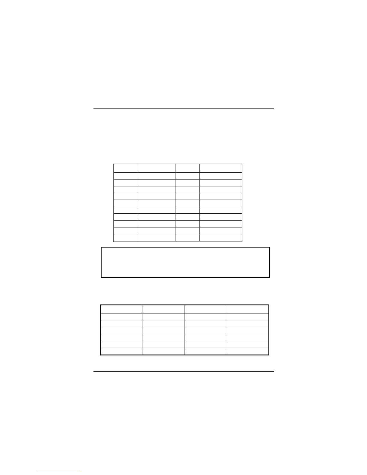
1.3.4 ATX Power Connector (JATXPWR1)
This connector supports the power button on-board. Using the ATX power
supply, functions such as Modem Ring Wake-Up and Soft Power Off are
supported on this motherboard. This power connector supports instant
power-on function ality, which means tha t th e system will b oot up instan tly wh en
the power connector is inserted on the board.
PIN Assignment PIN Assignment
1 3.3 V 11 3.3 V
2 3.3 V 12 -12 V
3 Ground 13 Ground
4 5 V 14 PS_ON
5 Ground 15 Ground
6 5 V 16 Ground
7 Ground 17 Ground
8 PW_OK 18 -5 V
9 5V_SB 19 5 V
10 12 V 20 5 V
Warning: Since the motherboard has the instant power on function,
make sure that all components are installed properly before
inserting the power connector to ensure that no damage will be
done.
1.3.5 AT Pow er C on nector (JATPWR1)
PIN Assignment PIN Assignment
1 PW_OK 7 Ground
2 5V 8 Ground
3 12V 9 -5V
4 -12V 10 5V
5 Ground 11 5V
6 Ground 12 5V

Chapter 1 Motherboard Description
1-13
1.4 Serial and Parallel Interface Ports
This system is equ i pped with on e s erial p orts an d one par a llel por t. Both typ es of
interface ports will be e xpla i ne d in this cha pt e r.
The Serial Interface Port
The serial interface port is sometimes referred to as a RS-232 port or an
asynchronous communications port. Mice, printers, modems and other peripheral
devices can be connected to a serial port. The serial port can also be used to
connect your computer with another computer system. If you wish to transfer the
contents of your h ard disk to another system it can be acco mpl is hed by using each
machine‘s serial port.
The serial ports on this system have two types of connectors, one 9-pin and one
25-pin. Some older computer systems and peripherals may only have a 25-pin
connector. Should you need to connect your 9-pin serial port to a 25-pin serial
port, you can purchase a 9-to-25 pin adapter.

Chapter 1 Motherboard Description
1-14
Connectivity
The many ways that a serial port can be used make it necessary to be familiar with
the pinout dia gram. T h e f ollowin g chart gi ves yo u th e fu nct ion of each pi n on th e
9-pin conn ector. T his i nfor matio n can b e used when con figuri ng certai n sof twar e
programs to work with the serial port.
Signal Name DB9 PIN DB25 PIN
DCD Data Carrier Detect 1 8
RX Receive Data 2 3
TX Transmit Data 3 2
DTR Data Terminal Ready 4 20
GND Signal Ground 5 7
DSR Data Set Ready 6 6
RTS Request to Send 7 4
CTS Clear to Send 8 5
RI Ring Indicator 9 22
Chapter 1 Motherboard Description
1-15
The Serial Interface Port-II : JCOM1
Signal Name IDC PIN
DCD Data Carrier Detect 1
RX Receive Data 2
TX Transmit Data 3
DTR Data Terminal Ready 4
GND Signal Ground 5
DSR Data Set Ready 6
RTS Request to Send 7
CTS Clear to Send 8
RI Ring Indicator 9
Special Applications
There are two types of serial d evices that can be connected to a s erial port. One of
the devices is called “ DTE” (Data T erminal Equip ment) and the other devic e is
called “DCE” (Data Communications Equipment). If a modem is connected to a
computer, for example, the modem is called the DCE and the computer is called
the DTE. In situati ons such as this, th e pins on the serial ports can be conn ected
straight through.
In instances when there are two DTE devices connected together, such as a
computer and a printer, a special adapter called a “Null Modem” is needed to
make communication between the two devices possible.
When using the serial port to communicate between devices, one problem in
particular may arise. Some manufacturers use one set of signals to begin
communication with another device and other manufacturers do not use these
signals to initiate communication. If you enco unter a communication problem that
cannot be resolved using a null modem, it can generally be assumed that one
device is using the initialization signals and the other device is not. This can
usually be resolved by wiring the RTS, CTS, and DCD pins together.
2
1
10
9

Chapter 1 Motherboard Description
1-16
Serial Port/COM Port
The one serial port on the computer is called JCOM1, respectively. If you wish,
two more serial ports can be added onto the co mputer using opt ional hardware.
Should you choose to add the extra Serial ports (COM ports), they would be
called JCOM3.
When using serial ports to communicate with a peripheral devices, b e sure to
assign only one COM port number to ea ch devi ce. For ex ampl e, if a printer an d a
scanner are both connected to your computer through serial ports the printer must
be assigned one C OM port (i.e. COM1) and the scann er must be assigned the
other COM port (i.e. COM2). No two devices can be assigned to one COM port.
Each peripher al m us t hav e its own COM port.
NOTE: Two serial ports may be installed on the computer. However,
no more than two ports can be used simultaneously.
*If you have inst alled an internal mod em, be careful not to ass ign a COM port
number that has already been assigned to another device. This error is common.
When installing a d evice that is going to requ ire the use of a serial port, us e a
diagnostic program to find out which ports are available. It may be necessary to
remove expansion cards that have serial ports in order to check their jumper
settings. The j umper settings will indicat e which COM port the card ha s been
assigned. Checking the expansion card will eliminate mistakes in overlapping
COM ports. Once you have completed the installation of peripheral devices using
the serial ports , be sure that the co mmunication par ameters such as baud rat e,
parity bit, etc. are matching. If your computer is set for a baud rate of 9600 and
your modem is set for a baud rate of 2400, you will not be able to send messages.
The manuals that accompany the peripheral devices will inform you on the
procedure for setting their parameters. Software manuals will also have
instructions o n se tt ing param e ters.
Chapter 1 Motherboard Description
1-17
Parallel Interface Port
Unlike the serial port, parallel interface ports have been standardized and should
not present any difficulty interfacing peripherals to your system. Sometimes
called Centronics port, the parallel port is almost exclusively used with printers.
The parallel port on your system has a 25-pin Connector (see picture below). The
pinouts for the parall el port are shown in the table below .
Signal Pin
-Strobe 1
Data 0 3
Data 1 5
Data 2 7
Data 3 9
Data 4 11
Data 5 13
Data 6 15
Data 7 17
-Ack 19
Busy 21
Paper Empty 23
+Select 25
-Auto FDXT 2
-Error 4
-Init 6
-SLCTN 8
Ground 10
Ground 12
Ground 14
Ground 16
Ground 18
Ground 20
Ground 22
Ground 24
NC 26
1 2
25 26

Chapter 1 Motherboard Description
1-18
PS/2 Mouse Connector: (JMS2)
Pin Assignment
1 Data
2 No connect
3 Ground
4 +5 V (fused)
5 Clock
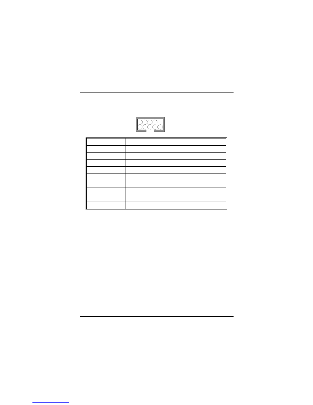
Game Port & Audio Connector: (JAUDJOY1)
Pin Assignment Pin Assignment
1 +5V 2 +5V
3 GP6 4 GP4
5 GP2 6 GP0
7 MIDI-OUTR 8 Ground
9 GP3 10 Ground
11 GP7 12 GP1
13 MIDI-INR 14 GP5
15 NC 16 +5V
17 Audio Left In 18 Audio Right In
19 Ground 20 Ground
21 Mono In 22 MIC bias voltage
23 Ground 24 Ground
25 Audio Left Out 26 Audio Right Out

Chapter 1 Motherboard Description
1-19
1.5 CPU Installation/Jumper Setting
1.5.1 CPU Installation Procedure
1. Pull the lever sid eways away from the sock et then raise the lever up to a
90-degre e a ng le.
2. Locate Pin A in the socket and look for the white dot or cut edge in the CPU.
Match Pin A with the white dot/cut edge then insert the CPU.
3. Press the lever dow n to co mplete the installa ti on .
S
o
c
k
e
t
3
7
0
 Loading...