

Page 1

I94GC-I7 Setup Manual
FCC Information and Copyright
This equipment has been tested and found to comply with the limits of a Class
B digital device, pursuant to Part 15 of the FCC Rules. These limits are designed
to provide reasonable protection against harmful interference in a residential
installation. This equipment generates, uses, and can radiate radio frequency
energy and, if not installed and used in accordance with the instructions, may
cause harmful interference to radio communications. There is no guarantee
that interference will not occur in a particular installation.
The vendor makes no representations or warranties with respect to the
contents here and specially disclaims any implied warranties of merchantability
or fitness for any purpose. Further the vendor reserves the right to revise this
publication and to make changes to the contents here without obligation to
notify any party beforehand.
Duplication of this publication, in part or in whole, is not allowed without first
obtaining the vendor’s approval in writing.
The content of this user’s manual is subject to be changed without notice and
we will not be responsible for any mistakes found in this user’s manual. All the
brand and product names are trademarks of their respective companies.
Page 2

Table of Contents
Chapter 1: Introduction .......................................................... 3
1.1 Before You Start ............................................................................ 3
1.2 Package Checklist......................................................................... 3
1.3 Mainboard Specifications.............................................................. 4
1.4 Rear Panel..................................................................................... 5
1.5 Mainboard Layout ........................................................................ 6
Chapter 2: Installation............................................................ 7
2.1 CPU ................................................................................................ 7
2.2 Fan Headers .................................................................................. 9
2.3 System Memory ........................................................................... 10
2.4 Power Supply............................................................................... 12
2.5 Onboard Slot/Connector/Header/Jumper.................................. 13
Chapter 3: BIOS Setup.......................................................... 19
3.1 Entering Setup............................................................................. 19
3.2 Using Setup.................................................................................. 19
3.3 Main Menu................................................................................... 20
3.4 Standard CMOS Features............................................................ 23
3.5 Advanced BIOS Features ............................................................ 25
3.6 Advanced Chipset Features........................................................ 30
3.7 Integrated Peripherals ............................................................... 34
3.8 Power Management Setup ......................................................... 40
3.9 PnP/PCI Configurations ............................................................. 44
3.10 PC Health Status......................................................................... 46
Chapter 4: RAID Functions ................................................... 48
4.1 Operating System........................................................................ 48
4.2 Raid Arrays.................................................................................. 48
4.3 How RAID Works......................................................................... 48
Chapter 5: Useful Help .......................................................... 51
5.1 Driver Installation Note.............................................................. 51
5.2 Phoenix-Award BIOS Beep Code ............................................... 52
5.3 Extra Information ....................................................................... 52
5.4 Troubleshooting........................................................................... 53
Page 3

I94GC-I7
3
CHAPTER 1: INTRODUCTION
1.1 B
EFORE YOU START
Thank you for choosing our product. Before you start installing the
mainboard, please make sure you follow the instructions below:
Prepare a dry and stable working environment with
sufficient lighting.
Always disconnect the system from power outlet
before operation.
Before you take the mainboard out from anti-static
bag, ground yourself properly by touching any safely
grounded appliance, or use grounded wrist strap to
remove the static charge.
Avoid touching the components on mainboard or the
rear side of the board unless necessary. Hold the board
on the edge, do not try to bend or flex the board.
Do not leave any unfastened small parts inside the
case after installation. Loose parts will cause short
circuits which may damage the equipment.
Keep the system from dangerous area, such as heat
source, humid air, and water.
1.2 P
ACKAGE CHECKLIST
Mini-ITX Mainboard x 1
Fully Setup Driver CD x 1
I/O Bracket x 1
IDE Cable x 1 (Optional)
SATA Cable x 1 (Optional)
Page 4

Mini-ITX Mainboard Manual
4
1.3 MAINBOARD SPECIFICATIONS
Specifications
CPU
LGA 775
Intel Core2Duo / Pentium 4 / Pentium D /
Celeron D processo r up to 3.8 GHz
*It is recommend ed to use proce ssors wi th
95W power consump tion.
Supports Hyper-Threading
Execute Disabl e Bit
Enhanced Intel SpeedS tep
Extended Memory 64 Technology
FSB 800 / 1066 MHz
Chipset
Northbri dge: Intel 945GC
Southbri dge: ICH7 or ICH7R
Graphic Intel GMA 950 Max Shared Video Memory is 224 MB
Super I/O
ITE IT8718
Provides the most commo nly used l egacy
Super I/O functionality.
Low Pin Count Int erface
Environment Control initiatives,
H/W Monitor
Fan Speed Controller
Main
Memory
DDR2 DIMM Slot x 2
Supports DDR2 667
Each DIMM supports 256MB/512MB/1GB/
2GB DDR2
Max Memory Capicity 4GB
Dual Channel Mode DDR2 memory module
Registered DIMM or ECC DIMM is not
supported
IDE
ICH7/ICH7R
Ultra DMA 33/66/ 100 Bus Maste r Mode
Supports PIO Mode 0~4
Supports 2 IDE devices
SATA
ICH7/ICH7R
SATA Version 2.0 specification compliant.
Data transfer rates up to 3.0 Gbit/s.
Supports RAID 0 / 1 / 0+ 1
LAN PHY RTL 8111C x2
10 / 100 / 1000 Mb/s auto nego tiation
Half / Full duplex capability
Sound
Codec
Real tek ALC66 2
5.1 channels audio out
High-Definition Audio support
Slots PCI Express x16 slot x1
IDE Connector x1
SATA2 Connector x4
Front Panel Connector x1
Front Audio Connector x1
Digital I/O Connector x1
CPU Fan Header x1
System Fan Header x1
On Board
Connector
Clear CMOS Header x1
Page 5
I94GC-I7
5
Specifications
Power Loss Recovery Header x1
USB 2.0 H eader x1
SIR Pin Header x1
Power Connec tor (4pin) x1
Power Conn ector ( 20pin) x1
Back Panel
I/O
PS/2 Keyboard x1
PS/2 Mous e x1
Serial Port x1
VGA Port x1
LAN port x2
USB Port x4
Audio Jack x3
Board Size 170 mm (W) x 170 mm (L) Mini-ITX
OS
Support
Windows XP / VISTA and Linux
Biostar Reserves th e right to add or remove
support for any OS with or without noti ce.
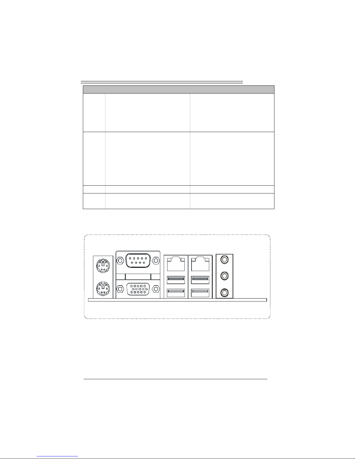
1.4 R
EAR PANEL
PS/2
Mouse
PS/2
Keyboard
VGA
COM Port
LAN LAN
USB 2.0 x 4
Line In/
Surround
Line Out
Mic In 1/
Bass/ Center
Page 6

Mini-ITX Mainboard Manual
6
1.5 MAINBOARD LAYOUT
JKBMS1
JCOM1
JUSBLAN1
JUSBLAN2
JSFAN1
JAUDIO1
SATA2
SATA1
JATXPWR1
IDE1
DDR2_A1
JVGA1
JIR1
JAUDIOF1
JUSB3
DDR2_B1
PEX16_1
JCMOS1
JCFAN1
JATXPWR2
LGA775
CPU1
ICH7/
ICH7R
Intel
945GC
BATTERY
BIOS
DIO
SATA3
JAP
JPANEL1
SATA4
Note: represents the 1■
st
pin.
Page 7

I94GC-I7
7
CHAPTER 2: INSTALLATION
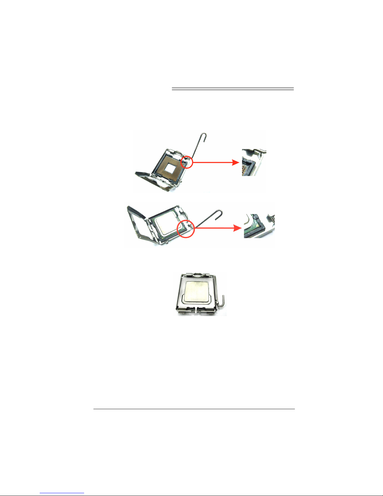
2.1 CPU
The mainboard comes with the socket LGA775 for Intel Core2Duo /
Pentium 4 / Pentium D / Celeron D processors, it supports new generation
of Intel Core2Duo processors with 800/1066 MHz of front side bus. Please
follow the instruction to install the CPU properly.
Special Notice:
Remove Pin Cap before installation, and make good preservation
for future use. When the CPU is removed, cover the Pin Cap on the
empty socket to ensure pin legs won’t be damaged.
Pin-Cap
Step 1: Pull the socket locking lever out from the socket and then raise
the lever up to a 90-degree angle.
Page 8
Mini-ITX Mainboard Manual
8
Step 2: Look for the triangular cut edge on socket, and the golden dot on
CPU should point forwards this triangular cut edge. The CPU will
fit only in the correct orientation.
Step 2-1:
Step 2-2:
Step 3: Hold the CPU down firmly, and then lower the lever to locked
position to complete the installation.
Step 4: Put the CPU Fan and heatsink assembly on the CPU and buckle it
on the retention frame. Connect the CPU FAN power cable into
the JCFAN1. This completes the installation.
Page 9

I94GC-I7
9
2.2 FAN HEADERS
These fan headers support cooling-fans built in the system. The fan
cable and connector may be different according to the fan manufacturer.
Connect the fan cable to the connector while matching the black wire to
GND.
CPU Fan Header
Pin Assignment
1 Ground
2 +12V
3FAN RPM rate
sense
4 Smart Fan
Control
1
4
System Fan Header
Pin Assignment
1 Ground
2 +12V
3 FAN RPM rate
sense
13
Note:
The CPU Fan Header and System Fan H eader support 4-pin and 3-pin head connector.
When connecting with wires onto connectors, pl ease note that the red wire is the p ositive
and shou ld be c onnected to pin#2, and the black wire is Ground and should be
connect ed to GND.
Page 10
Mini-ITX Mainboard Manual
10
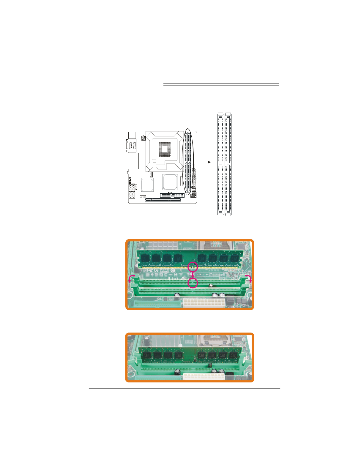
2.3 SYSTEM MEMORY
Memory Modules
DDR2_B1
DDR2_A1
1. Unlock a DIMM slot by pressing the retaining clips outward. Align a
DIMM on the slot such that the notch on the DIMM matches the
break on the Slot.
2. Insert the DIMM vertically and firmly into the slot until the retaining
chip snap back in place and the DIMM is properly seated.
Page 11

I94GC-I7
11
Memory Capacity
DIMM Socket
Location
DDR2 Module
Total Memory
Size
DDR2_A1 256MB/512MB/1GB/2GB
DDR2_B1 256MB/512MB/1GB/2GB
Max is 4GB.
Dual Channel Memory Installation
To trigger the Dual Channel function of the mainboard, the memory module must
meet the following requirements:
Install memory module of the same density in pairs, shown in the following table.
Single/Dual Channel Status
DDR2_A1
DDR2_B1
Single Channel O X
Single Channel X O
Dual Channel O O
(O means memory installed, X means memory not installed.)
The DRAM bus width of the memory module must be the same (x8 or x16)
Page 12

Mini-ITX Mainboard Manual
12
2.4 POWER SUPPLY
ATX Power Source Connector (20-pin)
This connector allows user to connect 20-pin power connector on the power
supply.
1
10
11
20
Pin Assignment Pin Assignment
1 +3.3V 11 +3.3V
2 +3.3V 12 -12V
3 GND 13 GND
4 +5V 14 Power Supply On
5 GND 15 GND
6 +5V 16 GND
7 GND 17 GND
8 Power Good 18 NC
9 +5V Standby 19 +5V
10 +12V 20 +5V
ATX Power Source Connector (4-pin)
By connecting this connector, it will provide +12V to CPU power circuit.
Pin Assignment
1 +12V
2 +12V
3 Ground
4 Ground
12
34
Page 13

I94GC-I7
13
2.5 ONBOARD SLOT/CONNECTOR/HEADER/JUMPER
PCI-Express x16 Slot
PCI-Express 1.0a compliant.
Maximum theoretical realized bandwidth of 4GB/s simultaneously per direction,
for an aggregate of 8GB/s totally.
PCI-Express supports a raw bit-rate of 2.5Gb/s on the data pins.
2X bandwidth over the traditional PCI architecture.
ATA Device Connector
The mainboard has an integrated IDE Controller that provides PIO Mode 0~4,
Bus Master, and Ultra DMA 33/66/100 functionality. It has one IDE connector
which can connect a master and a slave drive, so you can connect up to two
ATA devices.
1
2
39
40
Page 14

Mini-ITX Mainboard Manual
14
Front Panel Connector
This 10-pin connector includes Power-on, Reset, HDD LED, and Power LED
connection. It allows user to connect the system case’s front panel switch
functions.
9
12
10
Pin Assignment Function Pin Assignment Function
1 Key N/A 2 Power LED+
3 HD LED+ 4 Power LED +
5 HD LED-
HDD LED
6 Power LED-
Power LED
7 Reset GND 8 Power
9 Reset
Reset Button
10 Power GND
Power Button
Page 15
I94GC-I7
15
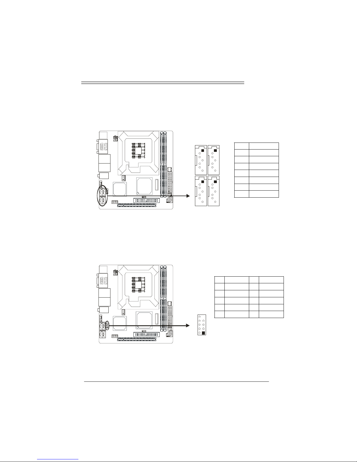
Serial ATA Connectors
These next generation connector support the thin Serial ATA cable for primary
internal storage devices. The current Serial ATA interface allows up to 3.0
Gbit/s data transfer rate.
Pin Assignment
1 GND
2 TX+
3 TX-
4 GND
5 RX-
6 RX+
7 GND
1
4
7
1
4
7
USB 2.0 Header
The mainboard provides a front USB pin header, allowing up to 2 additional
USB2.0 ports up to maximum throughput of 480 Mbps. Connect the 2-port
USB cable i nto this pi n header. This port can be used to connect high-speed
USB interface peripherals.
Pin Assignment Pin Assignment
10 NC 9 Key
8 Ground 7 Ground
6 USB1+ 5 USB0+
4 USB1- 3 USB0-
2 +5V (fused) 1 +5V (fused)
12
10
Page 16

Mini-ITX Mainboard Manual
16
Fast IrDA Infrared Module Connector
This connector is used to connect to an IrDA module. The BIOS settings must
be configured to activate the IR function.
Pin Assignment
1 +5V
2 CIRRX
3 IRRX
4 GND
5 IRTX
1
5
Front Panel Audio Connector
This is an interface for the front panel audio cable that allow convenient
connection and control of audio devices. This header allows only HD audio
front panel connector; AC’97 connector is not acceptable.
Pin Assignment
1 Mic Left in
2 Ground
3 Mic Right in
4 Present Sense
5 Right line out
6 Jack Sense
7 Front Sense
8 Key
9 Left line out
10 Jack Sense
12
910
Page 17

I94GC-I7
17
Digital I/O Connector
This connector offers 4-pair of digital I/O functions and address is set in BIOS.
The default address is: 801H: Output bit0~3; 802H: Input bit0~3.
Pin Assignment
1 5V
2 Digital-In-30
3 Digital-Out-20
4 Digital-In-31
5 Digital-Out-21
6 Digital-In-32
7 Digital-Out-22
8 Digital-In-33
9 Digital-Out-23
10 GND
1
2
9
10
Power Loss Recovery Header *
This header specifies how the system should do after a power fail. Setting
Disabled will leave the system in power off status after the power recovers.
Setting Enabled will power-on the system immediately when the power returns.
13
Pin 1-2 Close:
Enabled
1
3
13
Pin 2-3 Close:(default)
Disabled
Page 18

Mini-ITX Mainboard Manual
18
Clear CMOS Header *
By placing the jumper on pin2-3, it allows user to restore the BIOS safe setting
and the CMOS data, please carefully follow the procedures to avoid damaging
the mainboard.
13
Pin 1-2 Close:
Normal Operation(default).
13
13
Pin 2-3 Close:
Clear CMOS data.
※ Clear CMOS Procedures:
1. Remove AC power line.
2. Set the jumper to “Pin 2-3 close”.
3. Wait for five seconds.
4. Set the jumper to “Pin 1-2 close”.
5. Power on the AC.
6. Reset your desired password or cl ear the CMOS data.
*How to Setup Jumpers
The illustration shows how to set up jumpers. When the jumper cap is placed on
pins, the jumper is “close”, if not, that means the jumper is “open”.
Pin opened Pin closed Pin1-2 closed
Page 19

I94GC-I7
19
!! WARNING !!
For better system performance, the BIOS firmware is being
continuously updated. The BIOS information described in this
manual is for your reference only. The actual BIOS information
and settings on board may be slightly different from this manual.
CHAPTER 3: BIOS SETUP
3.1 E
NTERING SETUP
Power on the system and press <Delete> during the beginning of the boot
sequence to enter the BIOS setup menu. If you missed the BIOS setup entry
point, you may restart the system and try again.
3.2 USING SETUP
Use the arrow keys to highlight items in most of the place, press <Enter> to
select, use the <PgUp> and <PgDn> keys to change entries, press <F1> for
help and press <Esc> to quit. The following table provides more detail about
how to navigate in the Setup program by using the keyboard.
Keystroke Function
Up arrow Move to previous item
Down arrow Move to next item
Left arrow Move to the item on the left (menu bar)
Right arrow Move to the item on the right (menu bar)
Move Enter Move to the item you desired
PgUp key Increase the numeric value or make changes
PgDn key Decrease the numeric value or make changes
+ Key Increase the numeric value or make changes
- Key Decr ease the numeric value or make changes
Esc key
Main Menu – Quit and not save c hanges into CMOS
Status P age Setup Menu and Option Page Setup Menu – Exit
Current page and retur n to Main Menu
F1 key General help on Setup navigation keys
F5 key Load previous values from CMOS
F7 key Load the optimized def aults
F10 key Save all the CMOS changes and exit
Page 20

Mini-ITX Mainboard Manual
20
3.3 MAIN MENU
Once you enter Phoenix-Award BIOS™ CMOS Setup Utility, the Main Menu
will appear on the screen. The Main Menu allows you to select from several
setup functions. Use the arrow keys to select among the items and press
<Enter> to accept and enter the sub-menu.
Standard CMOS Features
This submenu contains industry standard configurable options.
Advanced BIOS Features
This subm enu allows you to configure advanced features of the BIOS.
Advanced Chipset Features
This subm enu allows you to configure special chipset features.
Integrated Peripherals
This subm enu allows you to configure certain IDE hard drive options and
Programmed Input/ Output features.
Power Management Setup
This subm enu allows you to configure the power management features.
Page 21

I94GC-I7
21
PnP/PCI Configurations
This subm enu allows you to configure certain “Plug and Play” and PCI options.
PC Health Status
This subm enu allows you to monitor the hardware of your system.
Load Optimized Defaults
This selection allows you to reload the BIOS when problem occurs during
system booting sequence. These configurations are factory settings optimized
for this system. A confirmation message will be displayed before defaults are
set.
Set Supervisor Password
Setting the supervisor password will prohibit everyone except the supervisor
from making changes using the CMOS Setup Utility. You will be prompted with
to enter a password.
Set User Password
If the Supervisor Password is not set, then the User Password will function in the
same way as the Supervisor Password. If the Supervisor Password is set and
the User Password is set, the “User” will only be able to view configurations but
will not be able to change them.
Page 22

Mini-ITX Mainboard Manual
22
Save & Exit Setup
Save all configuration changes to CMOS (memory) and exit setup. Confirmation
message will be displayed before proceeding.
Exit Without Saving
Abandon all changes made during the current session and exit setup.
Confirmation message will be displayed before proceeding.
Page 23

I94GC-I7
23
3.4 STANDARD CMOS FEATURES
Selections
This table shows the items and the available options on the menu of Standard
CMOS Features.
Item Options Description
Date mm : dd : yy
Set the system date. Note
that the ‘Day’ automatically
changes when you set the
date.
Time hh : mm : ss
Set the system internal
clock.
IDE Channel 0 Master
Options are in its sub
menu.
Press <Enter> to enter the
sub menu of detailed
options
IDE Channel 0 Slave
Options are in its sub
menu.
Press <Enter> to enter the
sub menu of detailed
options.
SATA 1/2/3/4 Device
Options are in its sub
menu.
Press <Enter> to enter the
sub menu of detailed
Page 24

Mini-ITX Mainboard Manual
24
Item Options Description
options.
Halt On
All Errors
No Errors
All, but Keyboard
Select the situation in
which you want the BIOS
to stop the POST process
and notify you.
Base Memory N/A
Displays the am ount of
conventional memory
detected during boot up.
Extended Memory N/A
Displays the am ount of
extended memory detected
during boot up.
Total Memory N/A
Displays the total memory
available in the system.
Page 25

I94GC-I7
25
3.5 ADVANCED BIOS FEATURES
CPU Features
Delay Prior to Thermal
This option controls the activation of the Thermal Monitor's automatic
mode. It allows you to determine when the Thermal Monitor should be
activated in automatic mode after the system boots.
The Choices: 4 Min / 8 Min / 16 Min (Default) / 32 Min
Page 26

Mini-ITX Mainboard Manual
26
Limit CPUID MaxVal
Set limit CPUID MaxVal to 3, it should be “Disabled” for Win XP.
The Choices: Disabled (Default) / Enabled
C1E Function
This item allows you to choose the C1E function.
The Choices: Auto (Default) / Disabled
Execute Disable Bit
When disabled, forces the XD feature flag to always return 0.
The Choices: Enabled (default) / Disabled
Boot Seq & Floppy Setup
Page 27

I94GC-I7
27
Hard Disk Boot Priority
This is for setting the priority of the hard disk boot order when the
“Hard Disk” option is selected in the “[First/Second/Third] Boot Device”
menu item.
The Choices: Pri. Master / Pri.Slave / Sec.Master / Sec.Slave /
USBHDD0 / USBHDD1 / USBHDD2 / Bootable Add-in Cards
First / Second / Third Boot Device
The BIOS will attempt to load the operating system in this order.
The Choices: LS120 / Hard Disk / CDROM / ZIP100 /
USB-FDD / USB-ZIP / USB-CDROM / Legacy LAN / Disabled
Boot Other Device
When enabled, BIOS will try to load the operating system from other
device when it failed to load from the three devices above.
The Choices: Enabled (Default) / Disabled
Page 28

Mini-ITX Mainboard Manual
28
Virus Warning
This option allows you to choose the VIRUS Warning feature that is
used to protect the IDE Hard Disk boot sector. If this function is enabled
and an attempt is made to write to the boot sector, BIOS will display a
warning message on the screen and sound an alarm beep.
The Choices: Enabled / Disabled (Default)
Quick Power On Self Test
Enabling this option will cause an abridged version of the Power On
Self-Test (POST) to execute after you power up the computer.
The Choices: Disabled Normal POST.
Enabled (Default) Enable quick POST.
Boot Up NumLock Status
Selects the NumLock State after the system switched on.
The Choices:
The Choices: On (Default) Numpad is number keys.
Off Numpad is arrow keys.
Gate A20 Option
Select if chipset or keyboard controller should control Gate A20.
The Choices: Fast (Default) Lets chipset control Gate A20.
Normal A pin in the keyboard controller
controls GateA20
Typematic Rate Setting
When a key is held down, the keystroke will repeat at a rate determined
by the keyboard controller. When enabled, the typematic rate and
typematic delay can be configured.
The Choices: Disabled (Default) / Enabled
Typematic Rate (Chars/Sec)
Sets the rate at which a keystroke is repeated when you hold the key
down.
The Choices: 6 (Default) / 8 / 10 / 12 / 15 / 20 / 24 / 30
(This option can be set only when “Typematic Rate Setting” is enabled.)
Page 29

I94GC-I7
29
Typematic Delay (Msec)
Sets the delay time after the key is held down before it begins to repeat
the keystroke.
The Choices: 250 (Default) / 500 / 750 / 1000
(This option can be set only when “Typematic Rate Setting” is enabled.)
Security Option
This option will enable only individuals with passwords to bring the
system online and/or to use the CMOS Setup Utility.
The Coices:
System A password is required for the system to boot and is
also required to access the Setup Utility.
Setup (default) A password is required to access the Setup Utility
only.
This will only apply if passwords are set from the Setup main menu.
APIC Mode
Selecting Enabled enables APIC device mode reporting from the BIOS
to the operating system.
The Choices: Enabled (Default) / Disabled
MPS Version Control For OS
The BIOS supports version 1.1 and 1.4 of the Intel multiprocessor
specification.
Select version supported by the operation system running on this
computer.
The Choices: 1.4 (Default) / 1.1
OS Select For DRAM > 64MB
A choice other than Non-OS2 is only used for OS2 systems with
memory exceeding 64MB.
The Choices: Non-OS2 (Default) / OS2
Small Logo(EPA) Show
This item allows you to select whether the “Small Logo” shows. Enabled
(default) “Small Logo” shows when system boots up. Disabled No “Small
Logo” shows when system boots
The Choices: Enabled (Default) / Disabled
Summary Screen Show
This item allows you to enable/disable the summary screen. Summary
screen means system configuration and PCI device listing.
The Choices: Disabled (Default) / Enabled
Page 30

Mini-ITX Mainboard Manual
30
3.6 ADVANCED CHIPSET FEATURES
DRAM Timing Selectable
When synchronous DRAM is installed, the number of clock cycles of
CAS latency depends on the DRAM timing.
The Choices: By SPD (Default) / Manual
CAS Latency Time
When synchronous DRAM is installed, the number of clock cycles of
CAS latency depends on the DRAM timing.
The Choices:5 (Default) / 4 / 3 / 6 / Auto
DRAM RAS# to CAS# Delay
This field let you insert a timing delay between the CAS and RAS strobe
signals, used when DRAM is written to, read from, or refreshed. Fast
gives faster performance; and slow gives more stable performance. This
field applies only when synchronous DRAM is installed in the system.
The Choices: 5 (Default) / 2 / 3 / 4 / 6 / Auto
Page 31

I94GC-I7
31
DRAM RAS# Precharge
If an insufficient number of cycles is allowed for RAS to accumulate its
charge before DRAM refresh, the refresh may be incomplete, and the
DRAM may fail to retain data. Fast gives faster performance; and Slow
gives more stable performance. This field applies only when
synchronous DRAM is installed in the system.
The Choices: 5 (Default) / 2 / 3 / 4 / 6 / Auto
Precharge Delay (TRAS)
This item controls the number of DRAM clocks to activate the precharge
delay.
The Choices: Auto (Default) / 4 / 5 / 6 / 7 / 8 / 9 / 10 / 11 / 12 / 13 / 14 /
15
System Memory Frequency
This item allows you to select the Memory Frequency.
The Choices: Auto (Default) / 400MHz / 533MHz / 667MHz
VGA Setting
PEG/Onchip VGA Control
This item allows you to enabled or disabled PEG/On-chip VGA
controller.
The Choices: Auto (Default) / Onchip VGA / PEG Port
On-Chip Frame Buffer Size
This item will be different as your memory modules. When the memory
size is decided, this frame buffer size will also be fixed.
The Choices: 8MB (Default) / 1MB
DVMT Mode
The Choices: DVMT (Default) / FIXED / BOTH
DVMT/FIXED Memory Size
DVMT stands for “Dynamic Video Memory Technology“. This is an
enhancemnet of the unified memory architecture (UMA) concept. Where
the optimum amount of memory is allocated for balanced graphics and
system performance. DVMT dynamically reponds to system
requirements and applications demands, by allocating the proper
amount of display, texturing and buffer memory after the operating
system has booted.
The Choices:128MB (Default) / 64MB / 224MB
Page 32

Mini-ITX Mainboard Manual
32
SLP S4# Assertion Width
This item sets the minimum assertion width of the SLP-S4# signal to
guarantee the DRAM has been safely power-cycled.
The Choices: 4 to 5 Sec. (Default) / 3 to 4 Sec. / 2 to 3 Sec. / 1 to 2
Sec.
System BIOS Cacheable
Selecting Enabled allows you caching of the system BIOS ROM at
F0000h~FFFFFh, resulting a better system performance. However, if
any program writes to this memory area, a system error may result.
The Choices: Enabled (Default) / Disabled
Video BIOS Cacheable
Select Enabled allows caching of the video BIOS, resulting a better
system performance. However, if any program writes to this memory
area, a system error may result.
The Choices: Disabled (Default) / Enabled
Memory Hole At 15M-16M
You can reserve this area of system memory for ISA adapter ROM.
When this area is reserved it cannot be cached. The user information of
peripherals that need to use this area of system memory usually
discussed their memory requirements.
The Choices: Disabled (Default) / Enabled
PCI Express Root Port Func
Page 33

I94GC-I7
33
Onboard PCIE GigaLAN #1/2
This option allows you to control the onboard Lan 1/2.
The Choices: Auto (Default) / Enabled / Disabled
PCIE GigaLan #1/2 Bootrom
Decide whether to invoke the boot ROM of the onboard Lan 1/2 chip.
The Choices: Disabled (Default) / Enabled
PCI-E Compliancy
This item allows you to select the PCI-E Compliancy Mode.
The Choices: v1.0a (Default) / v1.0
Page 34

Mini-ITX Mainboard Manual
34
3.7 INTEGRATED PERIPHERALS
OnChip IDE Device
Page 35

I94GC-I7
35
IDE HDD Block Mode
Block mode is also called block transfer, multiple commands, or
multiple sector read / write. If your IDE hard drive supports block mode
(most new drives do), select Enabled for automatic detection of the
optimal number of block mode(most new drives do), select Enabled
for automatic detection of the optimal number of block read / write per
sector where the drive can support.
The Choices: Enabled (Default) / Disabled
IDE DMA Transfer Access
This item allows you to enable or disable the IDE transfer access.
The Choices: Enabled (Default) / Disabled
On-Chip Primary/Secondary PCI IDE
This item allows you to enable or disable the primary/ secondary IDE
Channel.
The Choices: Enabled (Default) / Disabled
IDE Primary Master/Slave PIO
The IDE PIO (Programmed Input / Output) fields let you set a PIO
mode (0-4) for each of the IDE devices that the onboard IDE interface
supports. Modes 0 to 4 will increase performance progressively. In
Auto mode, the system automatically determines the best mode for
each device.
The Choices: Auto (Default) / Mode0 / Mode1 / Mode2 / Mode3 /
Mode4
IDE Primary Master/Slave UDMA
Ultra DMA functionality can be implemented if it is supported by the
IDE hard drives in your system. As well, your operating environment
requires a DMA driver (Windows 95 OSR2 or a third party IDE bus
master driver). If your hard drive and your system software both
support Ultra DMA, select Auto to enable BIOS support.
The Choices: Auto (Default) / Disabled
SATA Mode (RAID & AHCI are available only for ICH7R)
The Choices: IDE (Default) / RAID / AHCI
Page 36

Mini-ITX Mainboard Manual
36
On-Chip Serial ATA
This item allows you to choose:
Disabled: disabled SATA Controller
Combined Mode: PATA and SATA are combined max of 2 IDE drivers
in each channel.
Enhanced Mode: enabled both SATA and PATA max of 6 IDE drivers
are supported.
SATA Only: SATA is operating in legacy mode.
The Choices: Disabled / Enhanced Mode (Default) / SATA only.
SATA PORT Speed Settings
The Choices: Disabled (Default) / Force GEN I / Force GEN II
PATA IDE Mode
The Choices: Primary (Default)
Onboard Device
USB Controller
Select Enabled if your system contains a Universal Serial Bus (USB)
controller and you have USB peripherals.
The Choices: Enabled (Default) / Disabled
Page 37

I94GC-I7
37
USB 2.0 Controller
This entry is to enable or disable EHCI controller only. This BIOS
itself may/ may not have high speed USB support. If the BIOS has
high speed USB support built in, the support will automatically turn on,
when high speed device were attached.
The Choices: Enabled (Default) / Disabled
USB Keyboard Support
This item allows you to enable or disable the USB Keyboard Legacy
Support.
The Choices:Enabled Enable USB Keyboard Support.
Disabled (Default)Disable USB Keyboard Support.
USB Mouse Support
This item allows you to enable or disable the USB Mouse Legacy
Support.
The Choices: Enabled Enable USB mouse Support.
Disabled (Default) Disable USB mouse Support.
Onboard Azalia Audio
This item allows you to decide to enable or disable to support HD
Audio.
The Choices: Auto (Default) / Disabled
Page 38

Mini-ITX Mainboard Manual
38
SuperIO Device
Onboard Serial Port 1
Select an address and corresponding interrupt for the first and second
serial ports.
The Choices: 3F8/IRQ4 (Default) / Disabled / 2F8/IRQ3 / 3E8/IRQ4 /
2E8/IRQ3 / Auto
PWRON After PWR-Fail
This setting specifies whether your system will reboot after a power
fail or interrupts occurs.
Off (Default) Leaves the computer in the power off state.
On Reboots the computer.
Former-Sts Restores the system to the status before power
failure or interrupt occurs.
The Choices: Off (default) / On / Former-Sts.
CIR Port Address
This option allows you to set the CIR port address.
The Choices: Disabled (Default) / 220 / 228
CIR Port IRQ
This option allows you to set the CIR port IRQ.
The Choices: 11 (Default) / 5
Page 39

I94GC-I7
39
Watch Dog Mode Select
This option allows you to select the operation mode of Watch Dog.
The Choices: Disabled (Default) / Second / Minute
Watch Dog Timer Select
This option allows you to select the timer of Watch Dog.
The Choices: 1 (Default) / Min=0, Max=65535, Key in a DEC number
Page 40

Mini-ITX Mainboard Manual
40
3.8 POWER MANAGEMENT SETUP
ACPI & Wake Up Events
ACPI Function
This item displays the status of the Advanced Configuration and
Power Management (ACPI).
The Choices: Enabled (Default) / Disabled
Wake-Up by PCI card
When you select “Enable”, a PME signal from PCI card returns the
system to Full On state.
The Choices: Disabled (Default) / Enabled
Page 41

I94GC-I7
41
Power On by Ring
An input signal on the serial Ring Indicator (RI) line (in other words, an
incoming call on the modem) awakens the system from a soft off state.
The Choices: Disabled (Default) / Enabled
Resume by Alarm
When “Enabled”, you can set the date and time at which the RTC
(real-time clock) alarm awakens the system from Suspend mode.
The Choices: Disabled (Default) / Enabled
Date (of Month) Alarm
You can choose which date the system will boot up.
Date (of Month) Alarm
You can choose the system boot up time, input hour, minute and
second to specify.
Reload Timer Events
Primary/Secondary IDE 0/1
You can select to enable or disable Primary or Secondary RAID 0 or
RAID 1 function under this item.
The Choices: Disabled (Default) / Enabled
FDD, COM, LPT Port
You can select to enable or disable FDD, COM, and LPT port under
this item.
The Choices: Disabled (Default) / Enabled
Page 42

Mini-ITX Mainboard Manual
42
PCI PIRQ [A-D]#
You can select to enable or disable PCI PIRQ [A-D]# under this item.
The Choices: Disabled (Default) / Enabled
Power Management
This category allows you to select the power saving method and is
directly related to the following modes:
1. HDD Power Down.
2. Suspend Mode.
There are three options of Power Management, three of which have
fixed mode settings.
The Choices:
Min Saving
Minimum power management.
Suspend Mode = 1 hr.
HDD Power Down = 15 Min
Max Saving
Maximum power management only available for sl CPU’s.
Suspend Mode = 1 min.
HDD Power Down = Disable
User Define (Default)
Allow you to set each option individually.
When you choose user define, you can adjust each of the item from
1 min. to 1 hr. except for HDD Power Down which ranges from 1 min.
to 15 min.
Video Off Method
This option determines the manner when the monitor goes blank.
The Choices:
V/H SYNC+Blank
This selection will cause the system to turn off the vertical and
horizontal synchronization ports and write blanks to the video buffer.
Blank Screen
This option only writes blanks to the video buffer.
DPMS (Default)
Initial display power management signaling.
Video Off In Suspend
This determines the manner in which the monitor is blanked.
The Choices: Yes (Default) / No
Page 43

I94GC-I7
43
Suspend Type
Select the Suspend Type.
The Choices: Stop Grant (Default) / PwrOn Suspend
Modem Use IRQ
This determines the IRQ, which can be applied in MODEM use.
The Choices: 3 (Default) / 4 / 5 / 7 / 9 / 10 / 11 / NA
Suspend Mode
The item allows you to adjust the system idle time before suspend.
The Choices: Disabled (Default) / 1 Min / 2 Min / 4 Min / 8 Min / 12 Min
/ 20 Min / 30 Min / 40 Min / 1 Hour
HDD Power Down
When enabled, the hard-disk drives will power down after a set time of
system inactivity. All other devices remain active.
The Choices: Disabled (Default) / 1 Min~15Min
Soft-Off by PWRBTN
This item determines the behavior of system power button. Instant off
turn off the power immediately, and Delay 4 Sec. will require you to
press and hold the power button for 4 seconds to cut off the system
power.
The Choices: Delay 4 Sec / Instant-Off (Default)
HPET Support
This item allows you to enable or disable HPET.
The Choices: Enabled (Default) / Disabled
HPET Modet
This item allows you to select the HPET mode.
The Choices: 32-bit mode (Default) / 64-bit mode
Page 44

Mini-ITX Mainboard Manual
44
3.9 PNP/PCI CONFIGURATIONS
Init Display First
This item allows you to decide to active whether PCI Slot or on-chip VGA
first.
The Choices: PCI Slot (Default) / Onboard
Resources Controlled By
By Choosing “Auto(ESCD)” (default), the system BIOS will detect the
system resources and automatically assign the relative IRQ and DMA
channel for each peripheral. By Choosing “Manual”, the user will need to
assign IRQ & DMA for add-on cards. Be sure that there are no IRQ/DMA
and I/O port conflicts.
The Choices: Auto (Default) / Manual
Page 45

I94GC-I7
45
IRQ Resources
This submenu will allow you to assign each system interrupt a type,
depending on the type of device using the interrupt. When you press the
“Press Enter” tag, you will be directed to a submenu that will allow you to
configure the system interrupts. This is only configurable when
“Resources Controlled By” is set to “Manual”.
IRQ-3 assigned to PCI Device
IRQ-4 assigned to PCI Device
IRQ-5 assigned to PCI Device
IRQ-7 assigned to PCI Device
IRQ-9 assigned to PCI Device
IRQ-10 assigned to PCI Device
IRQ-11 assigned to PCI Device
IRQ-12 assigned to PCI Device
IRQ-14 assigned to PCI Device
IRQ-15 assigned to PCI Device
PCI / VGA Palette Snoop
Some old graphic controllers need to “snoop” on the VGA palette and
then map it to their display as a way to provide boot information and
VGA compatibility. This item allows such snooping to take place.
The Choices: Disabled (Default) / Enabled
Maximum Payload Size
Set the maximum payload size for Transaction packets (TLP).
The Choice: 4096 (default.) / 128 / 256 / 512 / 1024 / 2048
Page 46

Mini-ITX Mainboard Manual
46
3.10 PC HEALTH STATUS
CPU FAN Control
Choose “smart” to reduce the noise caused by CPU FAN.
The Choices: Smart (Default) / Always On.
CPU Fan Off<℃>
If the CPU Temperature is lower than the set value, FAN will turn off.
The Choices: Min=0; Max=127; Key in a DEC number.
CPU Fan Start<℃>
CPU fan starts to work under smart fan function when arrive this set
value.
The Choices: Min=0; Max=127; Key in a DEC number.
CPU Fan Full speed <℃>
When CPU temperature is reach the set value, the CPU fan will work
under Full Speed.
The Choices: Min=0; Max=127; Key in a DEC number.
Page 47

I94GC-I7
47
Start PWM Value
When CPU temperature arrives to the set value, the CPU fan will work
under Smart Fan Function mode. The range is from 0~127, with an
interv al of 1.
The Choices: Min=0; Max=127; Key in a DEC number.
Shutdown Temperature
This item allows you to set up the CPU shutdown Temperature. This
item is only effective under Windows 98 ACPI mode.
The Choices: Disabled (Default) / 65℃/140℉/ 70℃/149℉ /
75℃/158℉
Show H/W Monitor in POST
If you computer contains a monitoring system, it will show PC health
status during POST stage. The item offers several different delay times.
The Choices: Enabled (Default) / Disabled
CPU Vcore / NB/SB Voltage / +3.3V / +12.0V / DDR Voltage / FSB
VTT / +5.0V / Voltage Battery
Detect the system’s voltage status automatically.
Current CPU Temp
This field displays the current temperature of CPU.
Current SYS Temp
This field displays the current temperature of the system.
Current CPU FAN Speed
This field displays the current speed of CPU fan.
Current SYS FAN Speed
This field displays the current speed SYSTEM fan.
Page 48

Mini-ITX Mainboard Manual
48
CHAPTER 4: RAID FUNCTIONS
4.1 O
PERATING SYSTEM
Supports Windows XP/Vista and Linux.
4.2 RAID ARRAYS
RAID supports the following types of RAID arrays:
RAID 0: RAID 0 defines a disk striping scheme that improves disk read and write times for
many applications.
RAID 1: RAID 1 defines techniques for mirroring data.
RAID 0+1: RAID 0+1 combines the techniques used in RAID 0 and RAID 1.
4.3 HOW RAID WORKS
RAID 0:
The controller “stripes” data across multiple drives in a RAID 0 array system. It breaks
up a large file into smaller blocks and performs disk reads and writes across multiple
drives in parallel. The size of each block is determined by the stripe size parameter,
which you set during the creation of the RAID set based on the system environment. This
technique reduces overall disk access time and offers high bandwidth.
Features and Benefits
Drives: Minimum 2, and maximum is up to 6 or 8. Depending on the
platform.
Uses: Intended for non-critical data requiring high data throughput, or any
environment that does not require fault tolerance.
Benefits: provides increased data throughput, especially for large files. No
capacity loss penalty for parity.
Drawbacks: Does not deliver any fault tolerance. If any drive in the array
fails, all data is lost.
Fault Tolerance: No.
Block 1
Block 3
Block 5
Block 2
Block 4
Block 6
Page 49

I94GC-I7
49
RAID 1:
Every read and write is actually carried out in parallel across 2 disk drives in a RAID 1
array system. The mirrored (backup) copy of the data can reside on the same disk or on a
second redundant drive in the array. RAID 1 provides a hot-standby copy of data if the
active volume or drive is corrupted or becomes unavailable because of a hardware failure.
RAID techniques can be applied for high-availability solutions, or as a form of automatic
backup that eliminates tedious manual backups to more expensive and less reliable
media.
Features and Benefits
Drives: Minimum 2, and maximum is 2.
Uses: RAID 1 is ideal for small databases or any other application that
requires fault tolerance and minimal capacity.
Benefits: Provides 100% data redundancy. Should one drive fail, the
controller switches to the other drive.
Drawbacks: Requires 2 drives for the storage space of one drive.
Performance is impaired duri ng drive rebuilds.
Fault Tolerance: Yes .
Block 1
Block 2
Block 3
Block 1
Block 2
Block 3
Page 50

Mini-ITX Mainboard Manual
50
RAID 0+1:
RAID 0 drives can be mirrored using RAID 1 techniques. Resulting in a RAID 0+1
solution for improved performance plus resiliency.
Features and Benefits
Drives: Minimum 4, and maximum is 6 or 8, depending on the platform.
Benefits: Optimizes for both fault tolerance and performance, allowing for
automatic redundancy. May be simultaneously used with other RAID levels
in an array, and allows for spare disks.
Drawbacks: Requires twice the available disk space for data redundancy,
the same as RAID level 1.
Fault Tolerance: Yes .
Block 2
Block 4
Block 6
Block 1
Block 3
Block 5
Block 2
Block 4
Block 6
Block 1
Block 3
Block 5
ICH7R
Page 51

I94GC-I7
51
CHAPTER 5: USEFUL HELP
5.1 D
RIVER INSTALLATION NOTE
After you installed your operating system, please insert the Fully Setup
Driver CD into your optical drive and install the driver for better system
performance.
You will see the following window after you insert the CD
The setup guide will auto detect your mainboard and operating system.
Note:
If this window didn’t show up after you insert the Driver CD, please use file browser to
locate and execute the file SETUP.EXE under your optical drive.
A. Driver Installation
To install the driver, please click on the Driver icon. The setup guide will
list the compatible driver for your mainboard and operating system. Click
on each device driver to launch the installation program.
B. Software Installation
To install the software, please click on the Software icon. The setup guide
will list the software available for your system, click on each software title
to launch the installation program.
C. Manual
Aside from the paperback manual, we also provide manual in the Driver
CD. Click on the Manual icon to browse for available manual.
Note:
You will need Acrobat Reader to open the manual file. Please download the latest version
of Acrobat Reader s oftware from
http://www.adobe.com/products/acrobat/readstep2.html
Page 52

Mini-ITX Mainboard Manual
52
5.2 PHOENIX-AWARD BIOS BEEP CODE
Beep Sound Meaning
One long beep followed by two short
beeps
Video card not found or video card
memory bad
High-low siren sound CPU overheated
System will shut down automatically
One Short beep when system boot-up No error found during POST
Long beeps every other second No DRAM detected or install
5.3 EXTRA INFORMATION
CPU Overheated
If the system shutdown automatically after power on system for
seconds, that means the CPU protection function has been activated.
When the CPU is over heated, the mainboard will shutdown
automatically to avoid a damage of the CPU, and the system may not
power on again.
In this case, please double check:
1. The CPU cooler surface is placed evenly with the CPU surface.
2. The CPU fan is rotated normally.
3. The CPU fan speed is fulfilling with the CPU speed.
After confirmed, please follow steps below to relief the CPU protection
function.
1. Remove the power cord from power supply for seconds.
2. Wait for seconds.
3. Plug in the power cord and boot up the system.
Or you can:
1. Clear the CMOS data.
(See “Close CMOS Header: JCMOS1” section)
2. Wait for seconds.
3. Power on the system again.
Page 53

I94GC-I7
53
5.4 TROUBLESHOOTING
Probable Solution
1. No power to the system at all
Power light don’t illuminate, fan
inside power supply does not turn
on.
2. Indicator light on keyboard does
not turn on.
1. Make sure power cable is
securely plugged in.
2. Replace cable.
3. Contact technical support.
System inoperative. Keyboard lights
are on, power indicator lights are lit,
and hard drive is spinning.
Using even pressure on both ends of
the DIMM, press down firmly until the
module snaps into place.
System does not boot from a hard disk
drive, but can be booted from optical
drive.
1. Check cable running from disk to
disk controller board. Make sure
both ends are securely plugged
in; check the drive type in the
standard CMOS setup.
2. Backing up the hard drive is
extremely important. All hard
disks are capable of breaking
down at any time.
System only boots from an optical
drive. Hard disks can be read,
applications can be used, but system
fails to boot from a hard disk.
1. Back up data and applications
files.
2. Reformat the hard drive.
Re-install applications and data
using backup disks.
Screen message shows “Invalid
Configuration” or “CMOS Failure.”
Review system’s equipment. Make sure
correct information is in setup.
System cannot boot after user installs a
second hard drive.
1. Set master/slave jumpers
correctly.
2. Run SETUP program and select
correct drive types. Call the drive
manufacturers for compatibility
with other drives.
2008/12/31
 Loading...