

Page 1

I945G-M7C Setup Manual
FCC Inf or m at ion and Copyright
This equipment has been tested and found to comply with the limits of a Class
B digital devic e, pursuant to Part 15 of the FCC Rules. These limits are designed
to provide reasonab le protec tio n ag ainst ha rmful i nterfe rence in a resi de ntia l
installation. This equipment generates, uses and can radiate radio frequency
energy and, if not installed and used in accordance with the instructions , may
cause harmful interference to radio communications. There is no guarantee
that i nterfe rence will not occ u r in a particula r ins ta llati o n.
The ve ndo r ma kes no rep res enta tio ns or warra n ties with respec t t o t h e
contents here and specially disclaims any implied warranties of merchantability
o r fi tn es s fo r any p u rp ose . F u rt he r t he ve nd o r res e rves the ri ght to rev is e t his
publication and to make changes to the c ontents here without obligation to
notify any party beforehand.
D uplic ation o f t his publ ication , in pa rt o r in whole , is no t allo wed wi t hout fi rst
obtaining the vendor’s approval in writing.
The content of this user’s manual is subject to be c hanged without notice and
we will not be responsible fo r any mis takes found in this user’s manual. A ll the
brand and product names are trademarks of their respec tive companies.
Page 2

Table of Contents
Chapter 1: Introduction .............................................1
1.1 Before You Start................................................................... 1
1.2 Package Checklist................................................................ 1
1.3 Motherboard Features..........................................................2
1.4 Rea r Pa nel Co n necto rs (fo r Ver 5 .x)....................................... 4
1.5 Rear Pa nel Co n necto rs (fo r Ver 6.x)....................................... 4
1.6 Mo t he r boa r d La yo u t (for Ve r 5.x).......................................... 5
1.7 Mot her boa r d La yo u t (for Ve r 6.x )..........................................6
Chapter 2: Hardware Installation..............................7
2.1 Installing Ce ntral Processing Unit (CPU)................................ 7
2.2 FAN He ade rs........................................................................ 9
2.3 Installing System Me mory.....................................................10
2.4 Con nectors a nd Slo ts............................................................12
Chapter 3: Headers & Jumpers Setup .....................14
3.1 How to Setup Ju mpe r s..........................................................14
3.2 Det ail Settin gs.....................................................................14
Chapter 4: Useful Help .............................................20
4.1 Driver Insta l lation Note.......................................................20
4.2 AWARD B IO S Bee p Code......................................................21
4.3 Extra Information................................................................21
4.4 Troubleshooting...................................................................23
Chapter 5: WarpSpeeder™ .......................................24
5.1 Introduction........................................................................24
5.2 System Requirement............................................................24
5.3 Installation.........................................................................25
5.4 WarpSpeeder™ ....................................................................26
Appendencies: SPEC In Other Language ................32
German................................................................................................32
France..................................................................................................34
Italian..................................................................................................36
Spanish................................................................................................38
Portuguese ...........................................................................................40
Polish...................................................................................................42
Russian................................................................................................44
Arabic..................................................................................................46
Japanese..............................................................................................48
Page 3

I945G-M7C
CHAPTER 1: INTRODUCTION
1.1 BEFORE YOU START
Tha nk you fo r choo sing our p ro duct. Be fore you start ins talling the
mo therboa rd, plea se make su re you fo llo w the ins tructions be lo w:
Prepare a dry and stable working environment with
s uf ficie nt li gh ting .
Always disconnect the computer from power outlet
be fo re ope ration .
Befo re you tak e the mo the rboa rd o u t f rom a n ti-s ta ti c
bag, ground yourself properly by touching any safely
grounde d ap plian ce, o r use grounded wrist strap to
remove the static charge.
Avo id tou ch ing the com pone nt s o n mo the rbo a rd o r the
rea r side of the boa rd unles s necessa ry. Ho ld the boa rd
on the edge, do no t try to be nd or flex the board.
Do no t lea ve an y unfastene d sma ll pa rts inside the
case after installation. Loose parts will cause short
circuits which may damage the equipment.
Keep the computer from dangerous area, such as heat
source , humid a ir and wa ter.
1.2 PACKAGE CHECKLIST
z HDD Cable X 1
z Use r’s Ma nual X 1
z Se ria l ATA Cab le X 1
z Fully Setup Driver CD X 1
z Rear I/O Panel for ATX Case X 1
z FDD Cable X 1 (optional)
z USB 2.0 Cable X1 (optional)
z S/PDIF Cable X 1 (optional)
z Se ria l ATA Po we r Cab le X 1 (o ptio nal)
1
Page 4
Motherboard Manual
/
/
1.3 MOTHERBOARD FEATURES
Ver 5.x Ver 6.x
LGA 77 5
Intel Core2Duo/ Pentium 4 / Pentium D /
CPU
FS B 533 / 800 / 1066 M Hz 533 / 800 / 1066 M Hz
Chipset
Super I/O
Main
Memory
Graphics
IDE
SATA 2
Celeron D processor up to 3.8 GHz
Supports Hyper Thre ading
Bit / Enhanced Intel S peedSt ep®/ Intel
Extended Memory 64 technology
Int el 9 45G
Intel ICH7
ITE I T 8712F
Provides the most commonly used legacy
Super I/O functionality.
Low Pin C ount Interf ace
Environment Co ntrol initiatives,
H/W Monitor
Fan S pee d Co nt roller
ITE' s "Smart G uardia n" fu nc t ion
DIMM Slots x 4
Eac h DIMM s up ports 2 56/ 512MB & 1GB
DDR2
Max Memory Capicity 4GB
Dual Channel Mode DDR 2 memory module
Supports D DR 2 400 / 533 / 667
Registered DIMM and ECC DIMM is not
support ed
Int el GM A 950
Max Shared Video Memory is 224MB
Integrated I DE Controller
Ultra DMA 33~100 Bus Master Mode
support s PIO Mo de 0~4,
Integrated Serial ATA Controller
Data transfer rates up to 3.0 Gb/s.
SATA Version 2.0 specification compliant.
Execute Disable
LGA 77 5
Intel Core2Duo/ Pentium 4 / Pentium D /
Celeron D processor up to 3.8 GHz
Supports Hyper Thre ading
Bit / Enhanced Intel S peedSt ep®/ Intel
Extended Memory 64 technology
Int el 9 45G
Intel ICH7
ITE I T 8712F
Provides the most commonly used legacy
Super I/O functionality.
Low Pin C ount Interf ace
Environment Co ntrol initiatives,
H/W Monitor
Fan S pee d Co nt roller
ITE' s "Smart G uardia n" fu nc t ion
DIMM Slots x 4
Eac h DIMM s up ports 2 56/ 512MB & 1GB
DDR2
Max Memory Capicity 4GB
Dual Channel Mode DDR 2 memory module
Supports D DR 2 400 / 533 / 667
Registered DIMM and ECC DIMM is not
support ed
Int el GM A 950
Max Shared Video Memory is 224MB
Integrated I DE Controller
Ultra DMA 33~100 Bus Master Mode
support s PIO Mo de 0~4,
Integrated Serial ATA Controller
Data transfer rates up to 3.0 Gb/s.
SATA Version 2.0 specification compliant.
Execute Disable
2
Page 5
I945G-M7C
g
Ver 5.x Ver 6.x
Realtek RTL 8 110S C / 81 00C (optio nal)
LAN
Sound
Codec
On Board
Connector
Back Panel
I/O
Board Size 244 (W) x 24 4 (L ) mm 244 (W ) x 24 4 (L) m m
OS
Suppor t
10 / 1 00 Mb/s / 1 Gb/s auto negotiation
(Gigabit bandwidth is for RTL 8110SC o nly)
Half / Full duplex capability
AL C 888
7.1 c ha nnels a udio out
Intel High Definition Audio
PCI Expr ess x 16 slot x1 PCI Expr ess x 16 slot x1
PCI Expr ess x 1 slot x1 PCI Expr ess x 1 slot x1 Slots
PCI s lot x2 PCI s lot x2
Floppy connector x1 Floppy connector x1
IDE C o nnect or x1 IDE Co nnector x1
SATA Connector x4 SATA Connector x4
Front Pa nel C o nnect or x1 Fr ont Pa nel C o nnect or x1
Front Audi o Connect or x1 Front Audi o Connect or x1
CD-in C o nnector x1 CD-i n Co nnect or x1
S/PDIF o ut connector x1 S/PDIF out connector x1
S/PDIF in connector (optional) x1 S/PDIF in connector (optional) x1
CPU Fan hea der x1 C PU Fan hea der x1
Sys t em Fan hea der x1 S ys tem Fan hea der x1
Chassis open header (optional) x1 Chassis open header (optional) x1
Clear CMOS header x1 Clear CMOS header x1
USB connector x2 USB connector x2
Power Connector (24pi n) x1 Power Connector ( 24pi n) x1
Power Connector (4pin) x1 Power Connector ( 4pin) x1
PS/2 Keyb oard x1
PS/2 Mo us e x1
Serial Port x1
Printer Port x1
VGA port x1
LAN port x1
USB Port x4
Audio Jack x6
Windows 2000 / XP / VISTA
Biostar Reserves the ri
support for any OS with or without notice.
ht t o add or remo ve
Realtek RTL 8 110S C / 81 00C (optio nal)
10 / 1 00 Mb/s / 1 Gb/s auto negotiation
(Gigabit bandwidth is for RTL 8110SC o nly)
Half / Full duplex capability
AL C 861V D
5.1 c ha nnels a udio out
Intel High Definition Audio
PS/2 Keyb oard x1
PS/2 Mo us e x1
Serial Port x1
Printer Port x1
VGA port x1
LAN port x1
USB Port x4
Audio Jack x3
Windows 2000 / XP / VISTA
Biostar Reserves t he right to add or remove
support for any OS with or without notice.
3
Page 6
Motherboard Manual
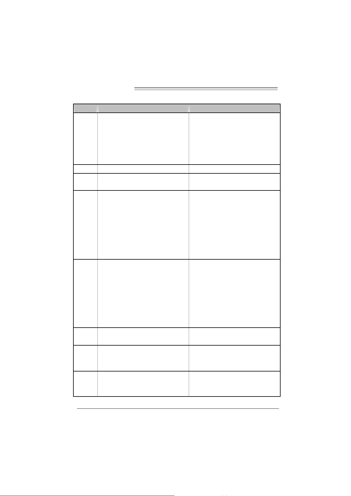
1.4 REAR PANEL CONNECTORS (FOR VER 5.X)
PS/2
Mouse
PS/2
Keyboard
Printer Port
COM1 VGA1 USBX2USBX2
Cent er
Rear
Sid e
Line In
Line Out
Mic In
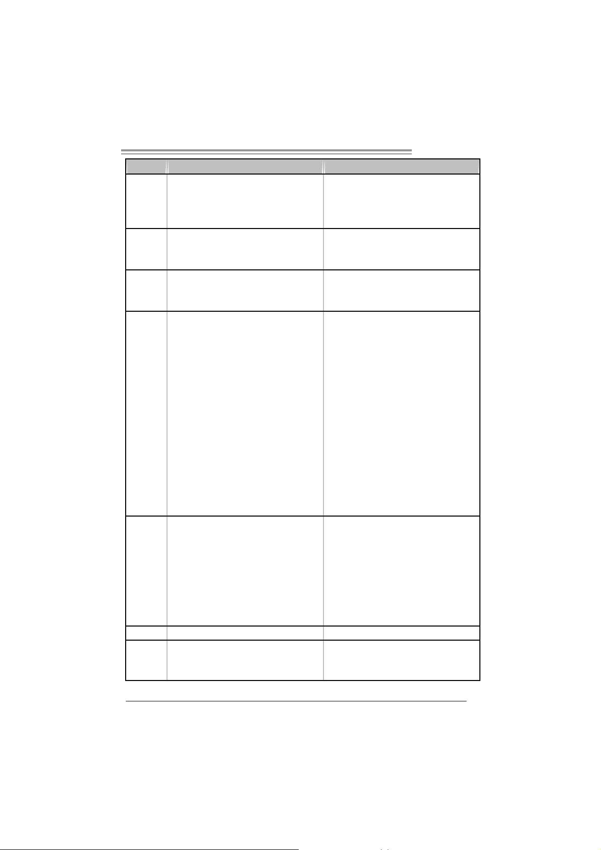
1.5 REAR PANEL CONNECTORS (FOR VER 6.X)
PS/2
Mouse
Printer Port
LAN
LAN
Line In/
Surround
PS/2
Keyboard
Since t he audio chip s upports Intel High Definition Audi o Specification, the function of each
audio jack can be defined by software. The input / out put function of each audio jack list ed
above represents t he def ault setti ng. However, when c onnecti ng exter nal microphone to t he
audio port, pl eas e us e the Line In (blue) and Mic In (Pi nk) audio jac k.
4
COM1 VG A1 USBX2USBX2
Line Out
Mic In 1/
Bass/ Center
Page 7
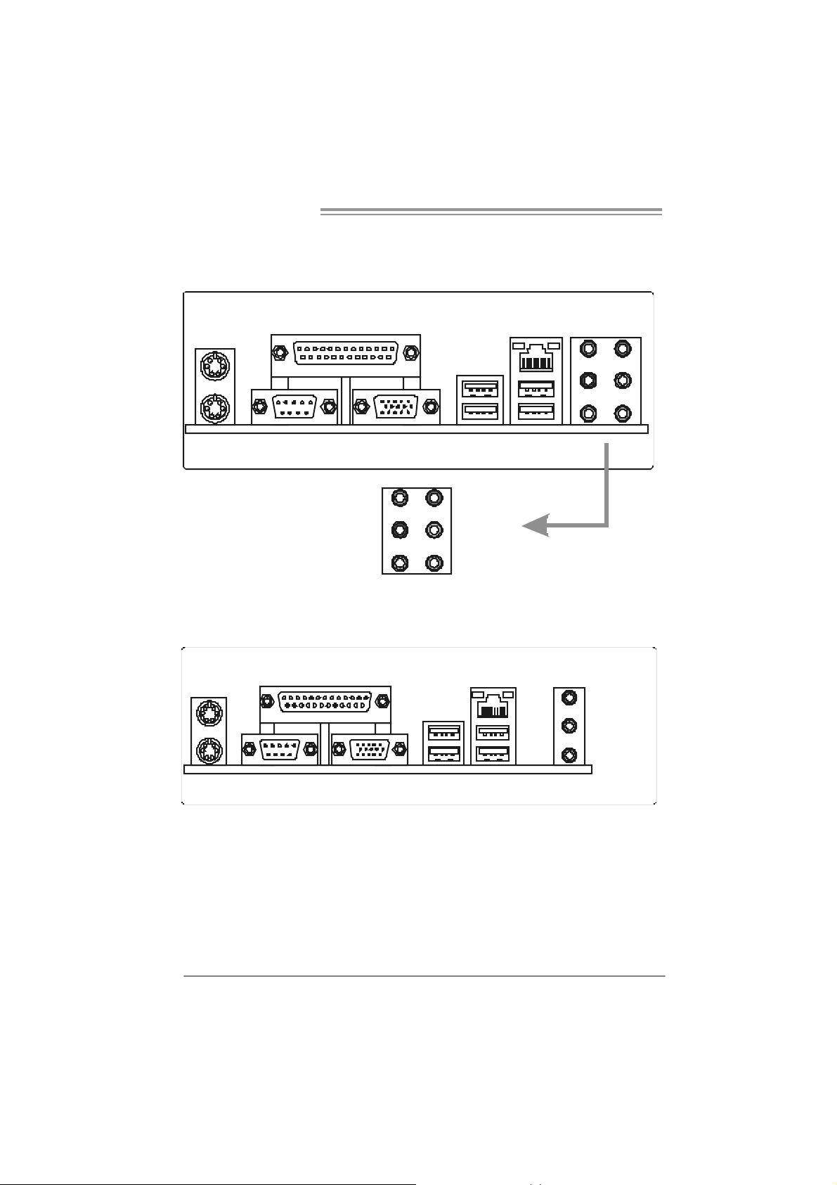
1.6 MOTHERBOARD LAYOUT (FOR VER 5.X)
JKBMS1
C
O
M
JCOM1
1
JVG A1
JPR NT1
JA TXPWR2
LGA775
CPU1
I945G-M7C
JC FAN1
FDD1
JRJ45USB1
JA UD IO 1
CODEC
Super
JAUDIOF1
JCDIN 2
LAN
Note: represents the 1■
I/O
PCI-EX1 _1
JSPDIF_OUT1
J ATXPWR1
JSPDI F_IN1(optional)
PCI-EX1 6
PC I1
PCI2
st
pin.
Intel
945G
BIOS
BAT1
Intel
ICH7
DDR2 _ A1
DDR2_A2
JCI1 (O ptio nal)
JCMOS1
DDR2 _ B1
SATA4
SATA2
JPANEL1
DDR2_B2
IDE1
SATA3
SATA1
JSFAN1
5
Page 8

Motherboard Manual
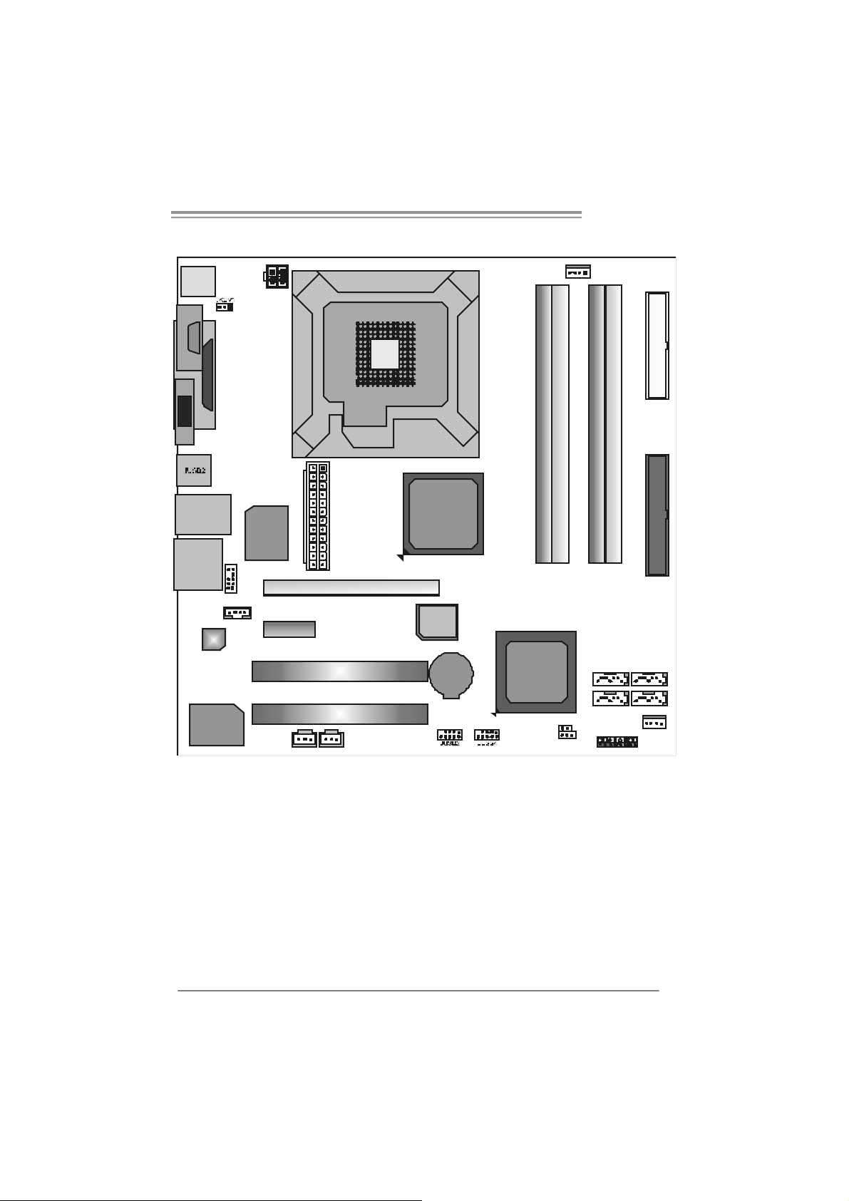
1.7 MOTHERBOARD LAYOUT (FOR VER 6.X)
JKBMS1
C
O
M
JCOM1
1
JVG A1
JPR NT1
JA TXPWR2
LGA775
CPU1
JC FAN1
FDD1
JRJ45USB1
JA UD IO 2
CODEC
Super
JAUDIOF1
JCDIN 2
LAN
Note: represents the 1■
I/O
PCI-EX1 _1
JSPDIF_OUT1
J ATXPWR1
JSPDI F_IN1(optional)
PCI-EX1 6
PC I1
PCI2
st
pin.
Intel
945G
BIOS
BAT1
Intel
ICH7
DDR2 _ A1
DDR2_A2
JCI1 (O ptio nal)
JCMOS1
DDR2 _ B1
SATA4
SATA2
JPANEL1
DDR2_B2
IDE1
SATA3
SATA1
JSFAN1
6
Page 9
I945G-M7C
CHAPTER 2: HARDWARE INSTALLATION
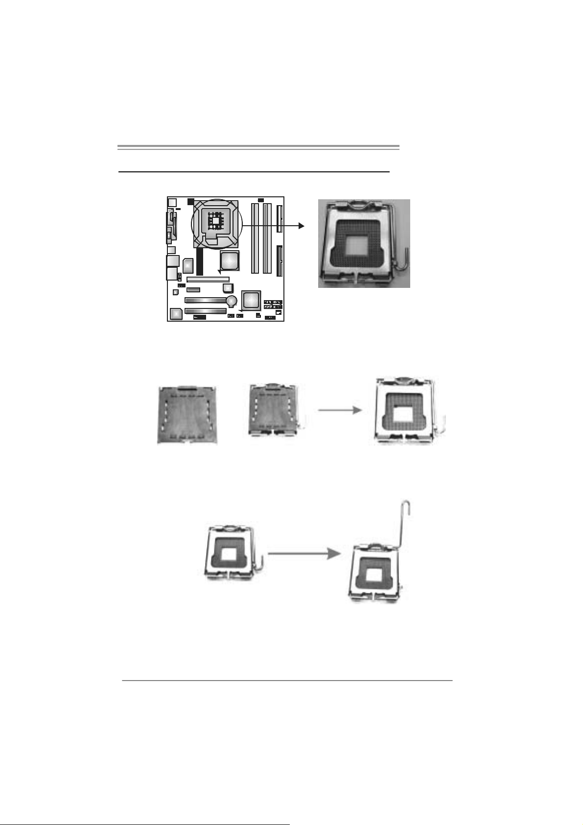
2.1 INSTALLING CENTRAL PROCESSING UNIT (CPU)
Special Notice:
Remo v e Pin Cap before installation, and m ake go o d pre serv ation
for future use. When the CPU is removed, cov er the Pin Cap o n the
empty so cket to ensure pin legs won’ t be dam ag ed.
Pin Cap
Step 1: Pul l the socket locking lever out from the socket and then raise
the lever up to a 90-degree angle.
7
Page 10
Motherboard Manual
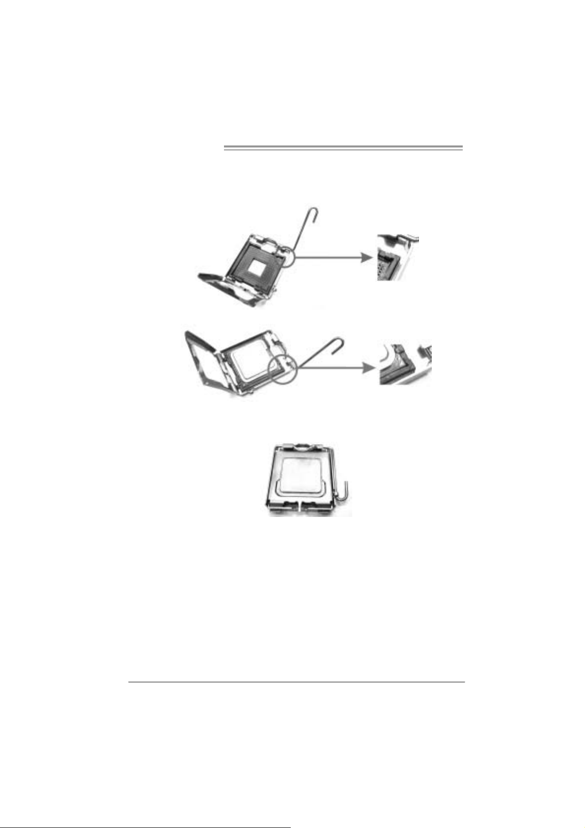
Step 2: Look for the triangul ar cut edge on socket, and the golden dot on
CPU should point forwards this tri angular cut edge. T he CPU will
fit only in the correct ori entation.
Step 2-1:
Step 2-2:
Step 3: Hol d the CPU down firmly, and then l ower the lever to locked
position to com plete th e installatio n.
Step 4: Put the CPU Fan and heatsink assembl y on the CPU and buckle it
on the retention frame. Connect the CPU FAN power cable into
the JCFAN1. This completes the i n stallation.
8
Page 11
I945G-M7C
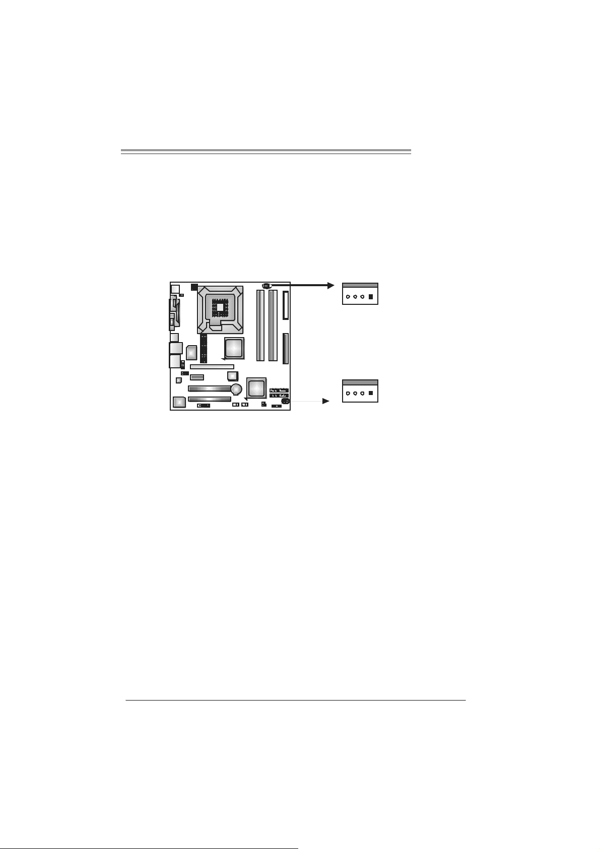
2.2 FAN HEADERS
These fan headers support cooling-fans built in the computer. T he fan
cabl e and connector may be different accordi ng to the fan manufacturer.
Connect the fan cable to the connector while matching the bl ack wire to
pin#1.
JCFAN1: CPU Fan Header
JSFAN1 : System Fan Head er
JCFAN1
4
1
JSFAN1
14
Note:
The JCFAN1 and JSFAN1 s upport 4-pin head c onnector. When c onnecti ng with wires
onto connec tors, pleas e note that the red wire is the positive and s hould be c onnected to
pin#2, and the black wire is Ground and s hould be connect ed to GND.
Pin
Assignment
1 Ground
2 +12V
3 FAN RPM rate
sense
4 Smart Fan
Control
9
Page 12
Motherboard Manual
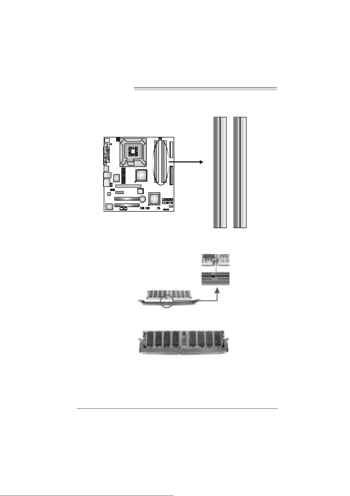
2.3 INSTALLING SYSTEM MEMORY
A. Me mo ry Modules
DDR2_A1
DDR2_ A2
DDR2_B1
1. Unlock a DIMM slot by pressing the retaining clips outward. Align a
DIMM on the slot such that the notch on the DIMM matches the
break on the Slot.
DDR2_ B2
2. Insert the DIMM vertically and firmly into the sl ot until the retaining
chip snap back in place and the DIM M is properly seated.
10
Page 13
I945G-M7C
B. Memory Capacity
DI MM Socket
Location
DDR2_A1 256MB/512MB/1GB *1
DDR2_A2 256MB/512MB/1GB *1
DDR2_B1 256MB/512MB/1GB *1
DDR2_B2 256MB/512MB/1GB *1
DDR Module
C. Dual Channel Memory installation
To t rigger t he Dual Channel f unction of t he motherboard, the mem ory m odule
must meet the following requiremen t s:
Install memory m odule of the sam e density in pairs , shown in the f ollowing
table.
Du al Channel Statu s
Enabled O X O X
Enabled X O X O
Enabled O O O O
(O means m emory install ed, X means mem ory not installed.)
The DRAM bus width of the memory m odul e must be the same (x8 or
x16)
DDR2_A1
DDR2_A2 DDR2_B1 DDR2_B2
To t a l M e m o r y
Size
Max is 4G B.
11
Page 14
Motherboard Manual
2.4 CONNECTORS AND SLOTS
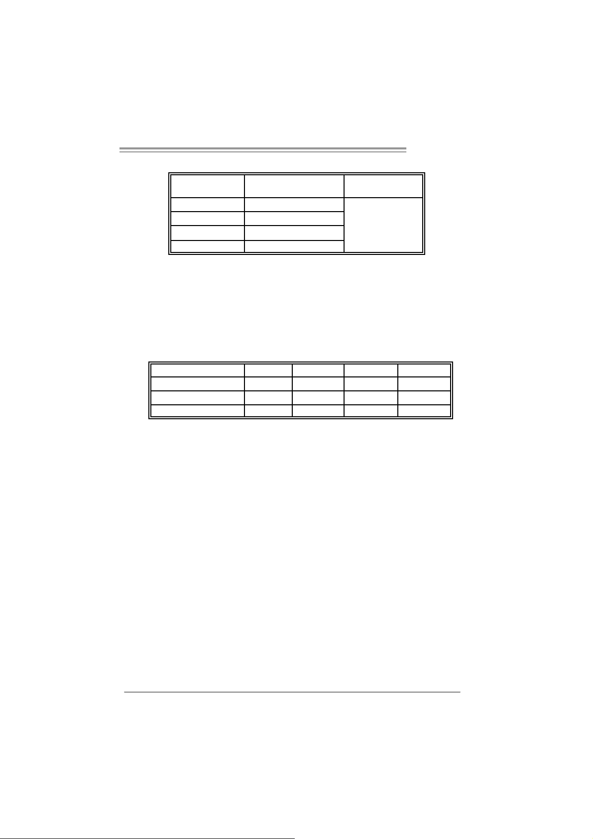
FDD1: Floppy Disk Connector
The motherboard prov ides a standard f loppy disk connector that supports 360K,
720K, 1. 2M, 1.44M and 2. 88M floppy disk types. This connec t or support s the
provided floppy drive ribbon cables.
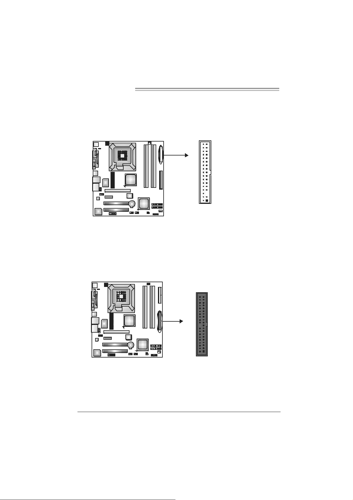
IDE1: Hard Disk Connectors
The motherboard has a 32-bit Enhanced PCI IDE Controller that prov ides PIO
Mode 0~4, Bus Master, and U lt ra D MA 33/ 66/ 100 functionality.
The IDE connectors can c onnec t a master and a s lav e driv e, so you c an
connec t up t o t wo hard disk drives .
34 33
12
12
3940
21
Page 15

I945G-M7C
PCI-EX 16: P CI-Expr es s x1 6 S lot
- PC I -Ex press 1.0a compliant.
- Maxim um theoretical realized bandwidt h of 4GB/s sim ult aneous ly per
direct ion, for an aggregat e of 8GB/ s tot ally.
PCI-EX1_1: PCI-Express x1 Slot
- PC I -Ex press 1.0a compliant.
- D at a transf er bandwidt h up t o 250MB/s per direc t ion; 500MB/s in t ot al.
- PC I -Ex press supports a raw bit-rat e of 2.5Gb/s on the dat a pins.
- 2X bandwidth ov er the t radit ional PCI architecture.
PCI-EX 16
PCI-EX 1_1
PCI1~ PCI2: Peripheral Com ponent Interconnect Slots
This mot herboard is equipped with 2 standard PCI slot s. PC I stands for
Peripheral Com ponent I nt erc onnect, and it is a bus st andard for expansion
cards . This PCI s lot is designated as 32 bits.
PCI1
PCI2
13
Page 16
Motherboard Manual
CHAPTER 3: HEADERS & JUMPERS SETUP
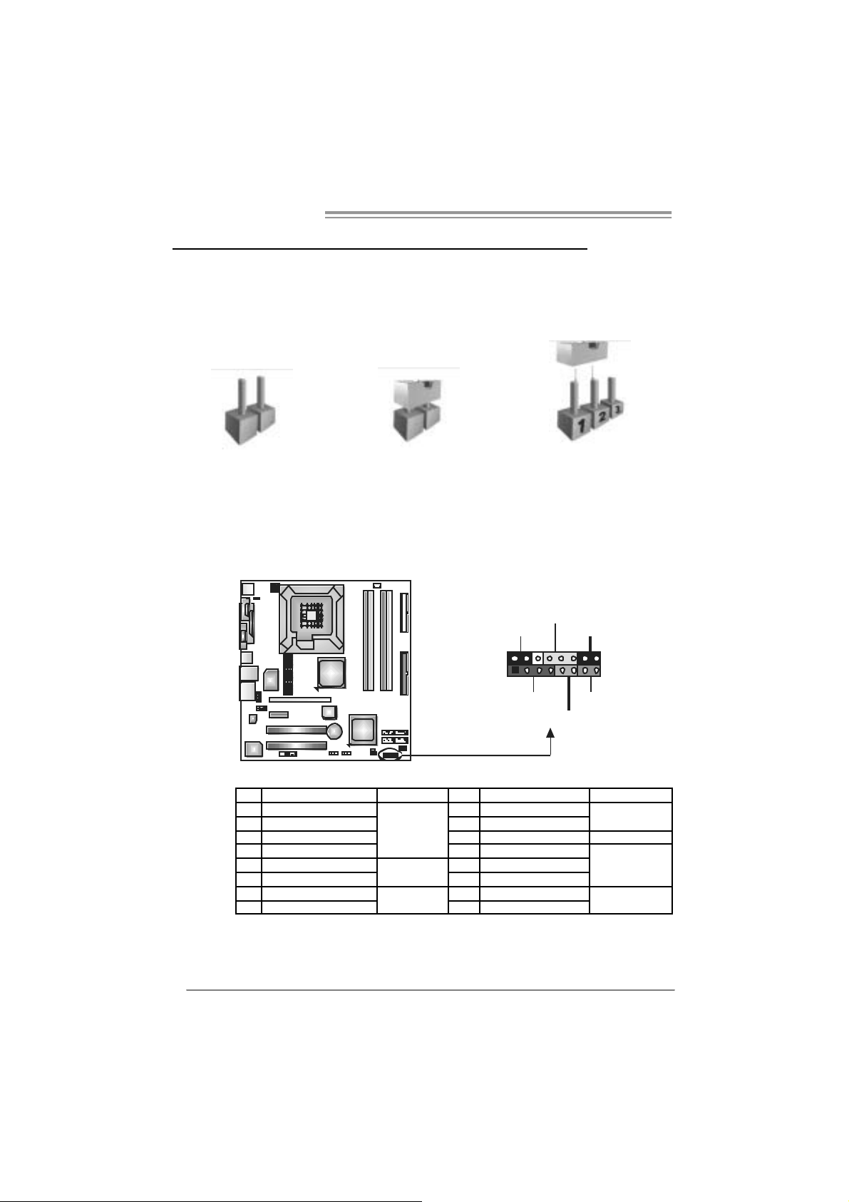
3.1 HOW TO SETUP JUMPERS
The illustration shows how to set up jumpers. When the j umper cap is
placed on pins, the jumper is “close”, if not, that means the jumper is
“open”.
Pin opened Pin closed Pin1-2 closed
3.2 DETAIL SETT INGS
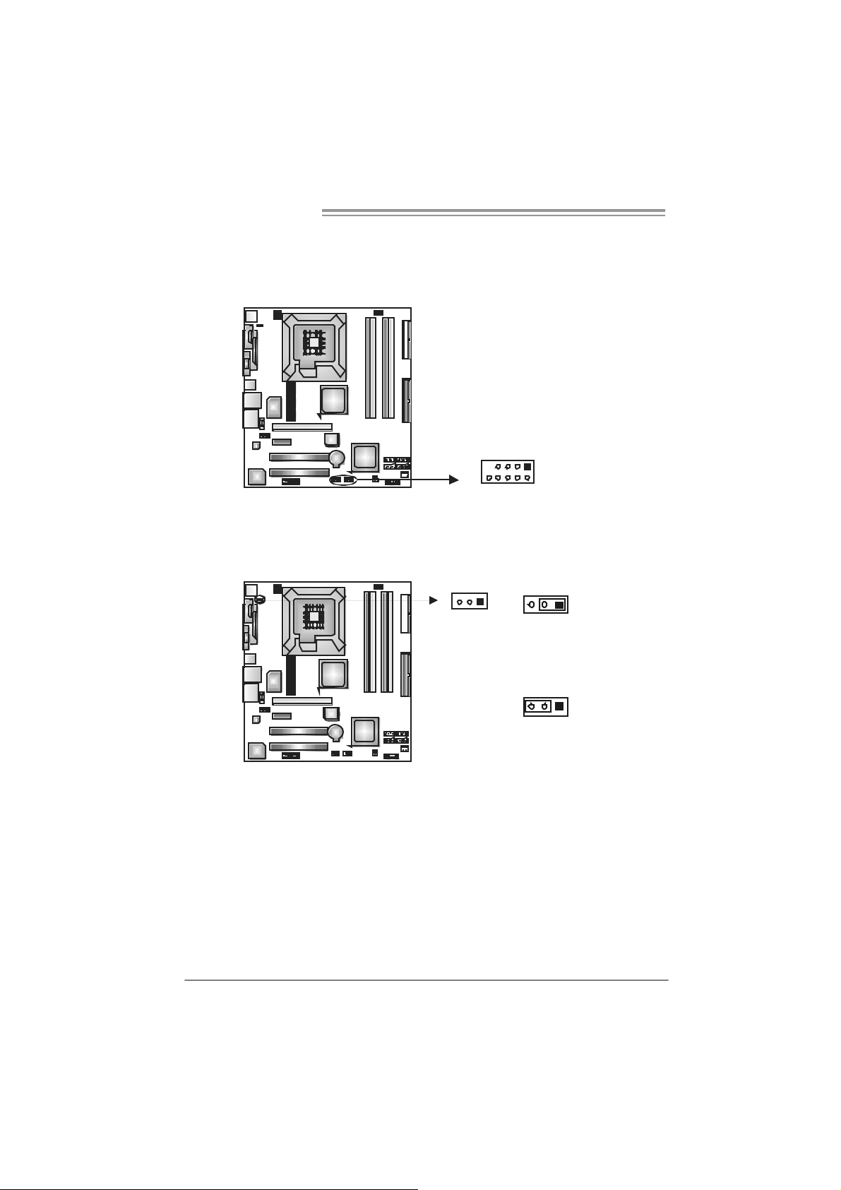
JPANEL1: Front Panel Header
This 16-pin connector includes Power-on, R eset, HDD LED, Power LED, Sleep
butt on and speak er C onnection. It allows user to c onnec t the PC case’s f ront
panel switch f unctions.
PWR_LED
SLP
9
18
SPK
++
HLED
+
On/Off
-
-
16
RST
16
14
Pin Assignment Functio n Pin Assignment Function
1 +5V 9 Sleep control
2 N/A 10 Ground
3 N/A 11 N/A N/A
4 Speaker
5 HDD LED (+) 13 Power LED (+)
6 HDD LED (-)
7 Ground 15 Power button
8 Reset control
Speaker
Connector
Hard drive
LED
Reset button
12 Power LED (+ )
14 Power LED (-)
16 Ground
Sleep button
Powe r LED
Power-on button
Page 17
I945G-M7C
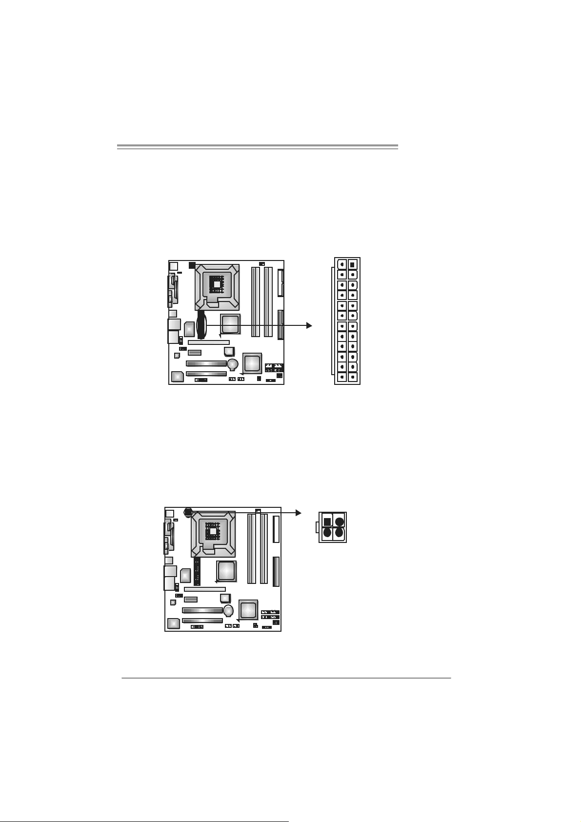
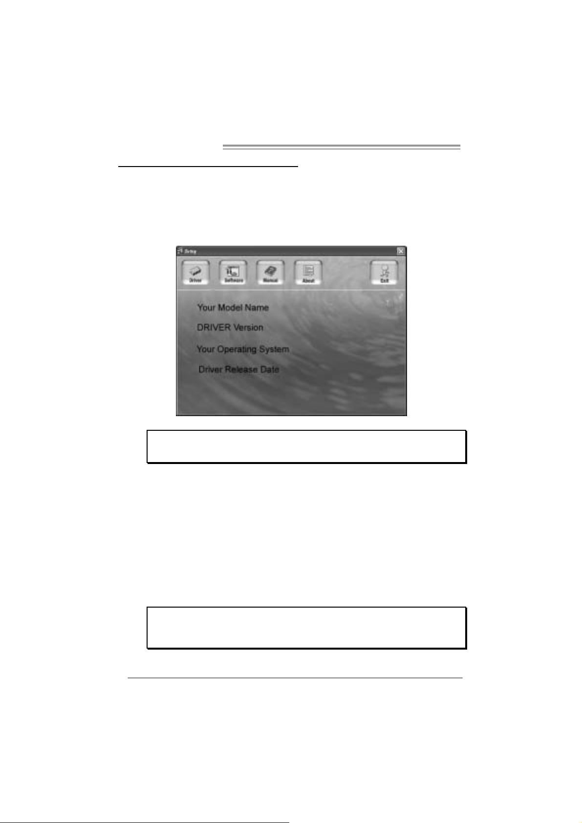
JA TXPWR1: ATX Power So u rce Conne ctor
This connector allows user t o c onnect 24-pin power connector on t he ATX power
supply.
Pin Assignment
1 +3.3V
2 +3.3V
3 Ground
4 +5V
5 Ground
13
1
6 +5V
7 Ground
8 PW_OK
9 Standby
10 +12V
11 +12V
12 2 x 12 Detect
13 +3.3V
14 -12V
15 Ground
16 PS_ON
17 Ground
1224
18 Ground
19 Ground
20 -5V
21 +5V
22 +5V
23 +5V
24 Ground
Voltage +5V
JA TXPWR2: ATX Power So u rce Conne ctor
By c onnecting this c onnector, it will prov ide +12V to CPU power circ uit.
1
4
23
Pin
Assignment
1 +12V
2 +12V
3 Ground
4 Ground
15
Page 18
Motherboard Manual
JUSB3/JUSB4: Headers for USB 2.0 Ports at Front Panel
This header allows us er t o connect additional USB c able on t he PC front panel,
and also can be c onnec t ed with internal U SB dev ic es, like USB card reader.
JUSB3 JUSB4
9
10
JKBV1: Power Source Header for PS/2 Keyboard and Mouse
31
13
+5V for PS/2 keyboard and
mouse.
31
PS/2 keyboard and mouse are
powered by +5V standby
voltage.
Note:
In order to support this function “Power-on system via keyboar d and mouse”, “JKBV1”
jumper cap should be plac ed on Pin 2-3.
Pin
1 +5V (fused)
2 +5V (fused)
3 USB4 USB5 USB+
6 USB+
7 Ground
8 Ground
9 Key
10 NC
1
2
Pin 1-2 Close
Pin 2-3 close
Assignment
(Default)
16
Page 19

I945G-M7C
JAUDIOF1: Fron t Panel Audio Header
This header allows us er t o connect t he f ront audio output cable wit h t he PC front
panel. It will dis able t he output on back panel audio connectors.
Pin
Assignment
1 Mic Left in
2 Ground
3 Mic Right in
4 GPIO
10
JCDIN2: CD-ROM Aud io-in Connector
This connector allows us er to connect the audio s ourc e from the variaty dev ices,
like CD-R OM, D VD -ROM, PCI sound card, PCI TV t urner card etc..
9
2
1
14
5 Right line in
6 Jack Sense
7 Front Sense
8 Key
9 Left line in
10 Jack Sense
Assignment
Pin
1 Left Channel
Input
2 Ground
3 Ground
4 Right Channel
Input
17
Page 20

Motherboard Manual
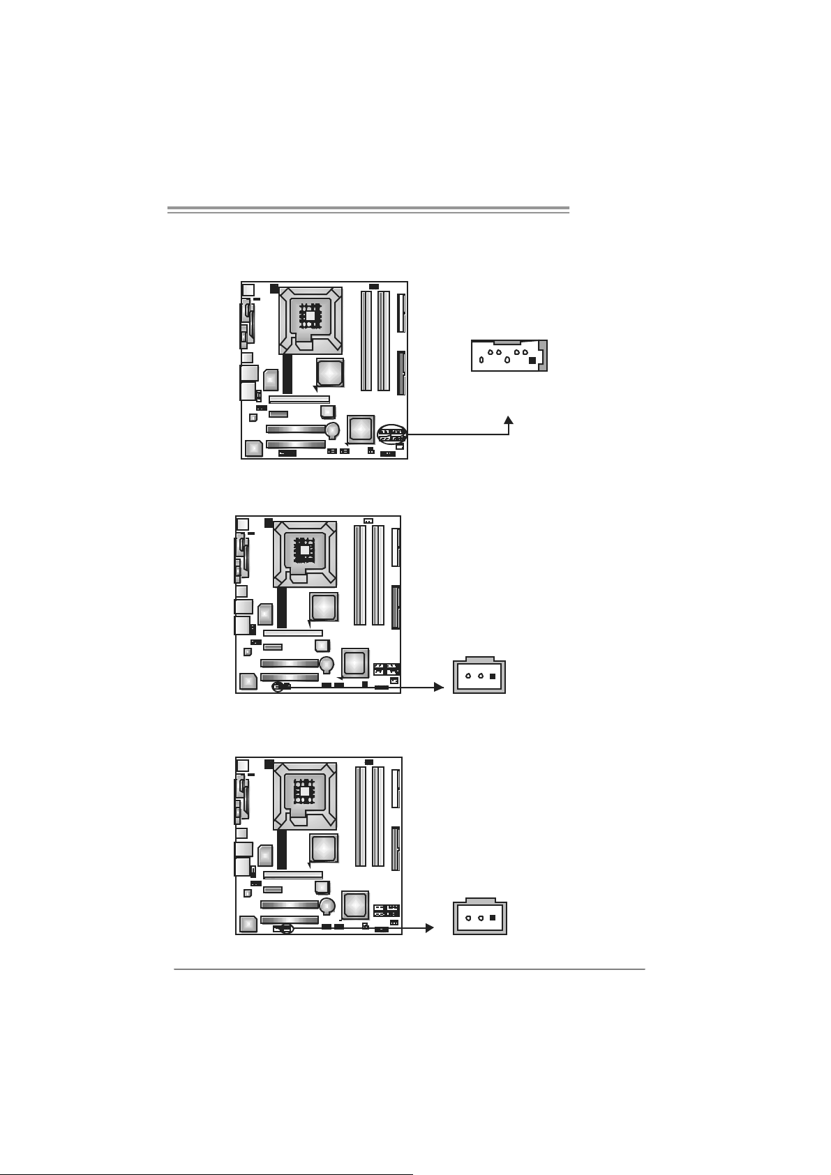
JCMOS1 : C l ea r CMOS H eader
By plac ing the jum per on pin2-3, it allows user t o restore the BIOS safe s etting
and the CMOS dat a, please carefully follow the procedures to avoid damaging
the m otherboard.
※ Clear CMOS Procedures:
1. Rem ov e AC power line.
2. Set the jumper to “Pin 2-3 close”.
3. Wai t for five seco n ds.
4. Set the jumper to “Pin 1-2 close”.
5. Power on the AC.
6. Res et your des ired password or clear the C MOS data.
1
3
Pin 1-2 Close:
Normal Operation (default).
1
3
13
Pin 2-3 Close:
Clear CMOS data.
JCI1: Chassis O p en Header (Optional)
This connector allows sy stem to m onitor PC case open stat us. If t he signal has
been triggered, it will rec ord t o the CMOS and s how t he message on next
boot-up.
18
Pin
Assignment
1 Case open signal
2 Ground
12
Page 21
I945G-M7C
SATA1~SATA4: Serial A TA C onnecto rs
The motherboard has a PCI t o SATA Controller with 4 channels SATA interfac e,
it satisfies the SATA 2.0 spec and with transfer rate of 3Gb/s.
SATA4 SATA3
147
SATA2 SATA1
JS PDIF_O UT1 : Di gital Audio- out Con n e ctor
This connector allows user t o c onnect the PCI brac k et SPDIF output header.
Pin
Assignment
1 +5V
2 SPDIF_OUT
3 Ground
Pin
Assignment
1 Ground
2 TX+
3 TX4 Ground
5 RX6 RX+
7 Ground
13
JSPDIF_IN1: Digital Audio-in Connector (Optional)
This connector allows user t o c onnect the PCI brac k et SPDIF input header.
Pin
Assignment
1 +5V
2 SPDIF_IN
3 Ground
13
19
Page 22
Motherboard Manual
CHAPTER 4: USEFUL HELP
4.1 D
RIVER INSTALLATION NOTE
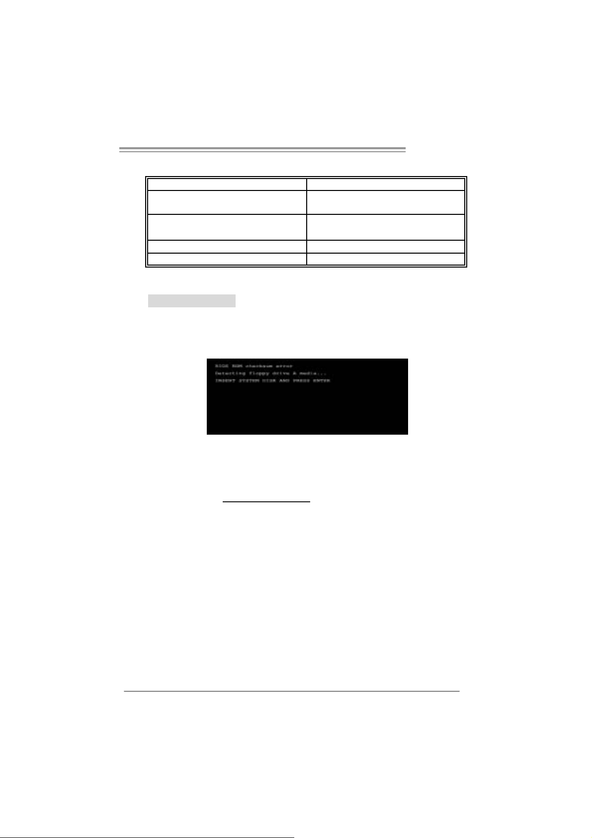
After you installed your operating system, please insert the Fully Setup
Dri ver CD into your optical drive and install the dri ver for better system
performance.
You will see the following window after you i nsert the CD
The set up guide will au to det ec t yo ur mothe rboa rd and operati ng system.
Note:
If this window didn’t show up after you ins ert the Driver CD, please use file browser to
l ocate an d e xecute the fi l e SETU P.EXE under your opt ic al dr i ve.
A. Driver Insta llation
To install the dri ver, please click on the Driver i con. The setup gui de wi ll
list the compatibl e driver for your motherboard and operating system.
Click on each device dri ver to launch the installation program.
B. Software Installation
To install the software, please cli ck on the Software icon. The setup guide
will list the software available for your system, click on each software titl e
to la unch the insta l lat io n pr ogr a m.
C. Manual
Asi de from the paperback manual, we also provide manual in the Driver
CD. Click on the Manual icon to browse for available manual.
Note:
You will need Acrob at Reader to open the m an ual file. Please dow nload the latest version
of Acrobat Reader software from
http://www.adobe.com/products/acrobat/readstep2.ht ml
20
Page 23
4.2 AWARD BIOS BEEP CODE
Beep Sound Meanin g
One long beep f ollowed by t wo s hort
beeps
High-low siren sound CPU ov erheat ed
One Short beep when system boot-up N o error found during POST
Long beeps every ot her s econd No DRAM detec t ed or ins t all
Video card not f ound or v ideo card
mem ory bad
Sys t em will s hut down automat ically
4.3 EXT RA INFORMATION
A. BIOS Update
After yo u fail to up d ate BIOS o r BIOS is i n vaded by virus, the
Boot-Block functi on wi ll help to restore BIOS. If the fol lowing message
is shown after boot-up the system, it means the BIOS contents are
corrupted.
In thi s Case, please follow the procedure below to restore the BIOS:
1. Mak e a bootab le fl op py disk .
2. Download the Flash Utility “AWDFLASH.exe” from the Biostar
websi te: www.bi o star.com .tw
3. Confi rm motherboard model and download the respectively BIOS
fr om Bi os t ar websit e.
4. Copy “AWDFLASH.exe” and respectively BIOS into floppy disk.
5. Insert the bootable disk into floppy dri ve and press Enter.
6. Sy stem will b oo t-u p t o DOS prompt.
7. Type “Awd flash xxxx.bf/ sn/py/ r” in DOS prompt.
(xxxx means BIOS nam e.)
8. Sy stem will u pd ate BIOS automati c ally an d re sta rt.
9. The BIOS has been recovered an d will work pro perly.
I945G-M7C
21
Page 24

Motherboard Manual
B. CPU Overheated
If the system shutdown automaticall y after power on system for
seconds, that means the CPU protecti on functi on has been activated.
When the CPU is over heated, the motherboard will shutdown
automatically to avoid a damage of the CPU, and the system may not
power on again.
In thi s case, please double check:
1. The CPU cool er surface is pl aced evenly with the CPU surface.
2. CPU fan i s rotate d normall y.
3. CPU fan speed i s fulfilling wi th the CPU speed.
After confirmed, pl ease follow steps below to relief the CPU protection
function.
1. Remove the power cord from power suppl y for seconds.
2. Wai t for seconds.
3. Plug i n the power cord and boot up the system.
Or you can:
1. Cl ear the CMOS data.
(See “Close CMOS Header: JCMOS1” section)
2. Wai t for seconds.
3. Pow er on the system again.
22
Page 25

4.4 TROUBLESHOOTING
e
Probable Solution
1. N o power to the system at all
Power light don’t illuminat e, f an
inside power s upply does not turn
on.
2. I ndic at or light on k ey board does
not t urn on.
Sys t em inoperat ive. Keyboard light s
are on, power indic at or lights are lit,
and hard drive is spinning.
Sys t em does not boot from hard dis k
drive, can be boot ed f rom opt ic al driv e.
Sys t em only boot s from opt ic al drive.
Hard disk can be read and applic ations
can be used but boot ing from hard dis k
is imposs ible.
Screen m essage say s “Inv alid
Conf igurat ion” or “C MOS Failure.”
Cannot boot sys t em after installing
sec ond hard driv e.
I945G-M7C
1. Make s ure power c able is
sec urely plugged in.
2. Replace cable.
3. Contact techni cal support.
Us ing even pres s ure on both ends of
the DIMM, press down f irm ly until the
module s naps int o plac e.
1. C hec k cable running f rom disk t o
disk controller board. Make s ure
both ends are s ec urely plugged
i n; ch ec k t he d riv e ty pe in th e
standard CMOS setup.
2. Bac k ing up the hard driv e is
ext rem ely im port ant . All hard
disk s are c apable of breaking
down at any t im e.
1. Bac k up data and applic at ions
files.
2. R ef orm at t he hard driv e.
Re-ins t all applicat ions and dat a
using backup disks.
Rev iew sys t em ’s equipment. Make sur
correc t inform at ion is in set up.
1. Set m aster/slave jum pers
correctly.
2. R un SETUP program and s elec t
correc t drive types. Call the drive
manufacturers for compatibilit y
with other drives.
23
Page 26

Motherboard Manual
CHAPTER 5: WARPSPEED ER™
5.1 INTRODUCTION
[WarpSpeeder™], a new powerful control utility, features three
user-friendly functions including Overclock M anager, Overvol tage
Manager, and Hardware Monitor.
With the Overclock Manager, users can easil y adj ust the frequency they
prefer or they can get the best CPU performance with just one cli ck. The
Overvoltage Manager, on the other hand, helps to power up CPU core
vol tage and Me mor y v ol tage. The co o l Har dw are Mo ni tor smar t ly in d ic at es
the tem peratures, voltage and CPU fan speed as well as the chipset
information. Also, in the About panel , you can get detail descripti ons about
BIOS model and chipsets. In addition, the frequency status of CPU,
memory, AGP and PCI along with the CPU speed are synchroni cally
s how n on our ma i n p an el .
Moreover, to protect users' computer systems i f the setting i s not
appropriate when testing and resul ts in system fail or hang,
[WarpSpeeder™] technol ogy assures the system stability by automatically
rebooting the computer and then restart to a speed that i s either the
ori ginal system speed or a suitable one.
5.2 SYS TEM REQUI REMENT
OS Support: Windows 98 SE, Windows M e, Wi ndows 2000, Windows XP
DirectX: DirectX 8.1 or above. (The Windows XP operating system
includes DirectX 8.1. If you use Windows XP, you do not need to install
Dir ec tX 8.1.)
24
Page 27

I945G-M7C
5.3 INSTALLATION
1. Execute the setup execution file, and then the following di alog will pop
up. Please click “Next” button and follow the default procedure to
install.
2. When you see the followi ng dialog in setup procedure, it means setup
is completed. If the “Launch the WarpSpeeder Tray Utility” checkbox
is checked, th e Tray Ico n utility and [Wa rpSpeeder™ ] util ity will b e
automatically and imm ediately launched after you click “Finish”
button.
Usage:
The following figures are j ust onl y for reference, the screen printed in
this user manual will chan ge a c c ordin g to your motherbo ard on ha nd.
25
Page 28
Motherboard Manual
5.4 WARPSPEEDER™
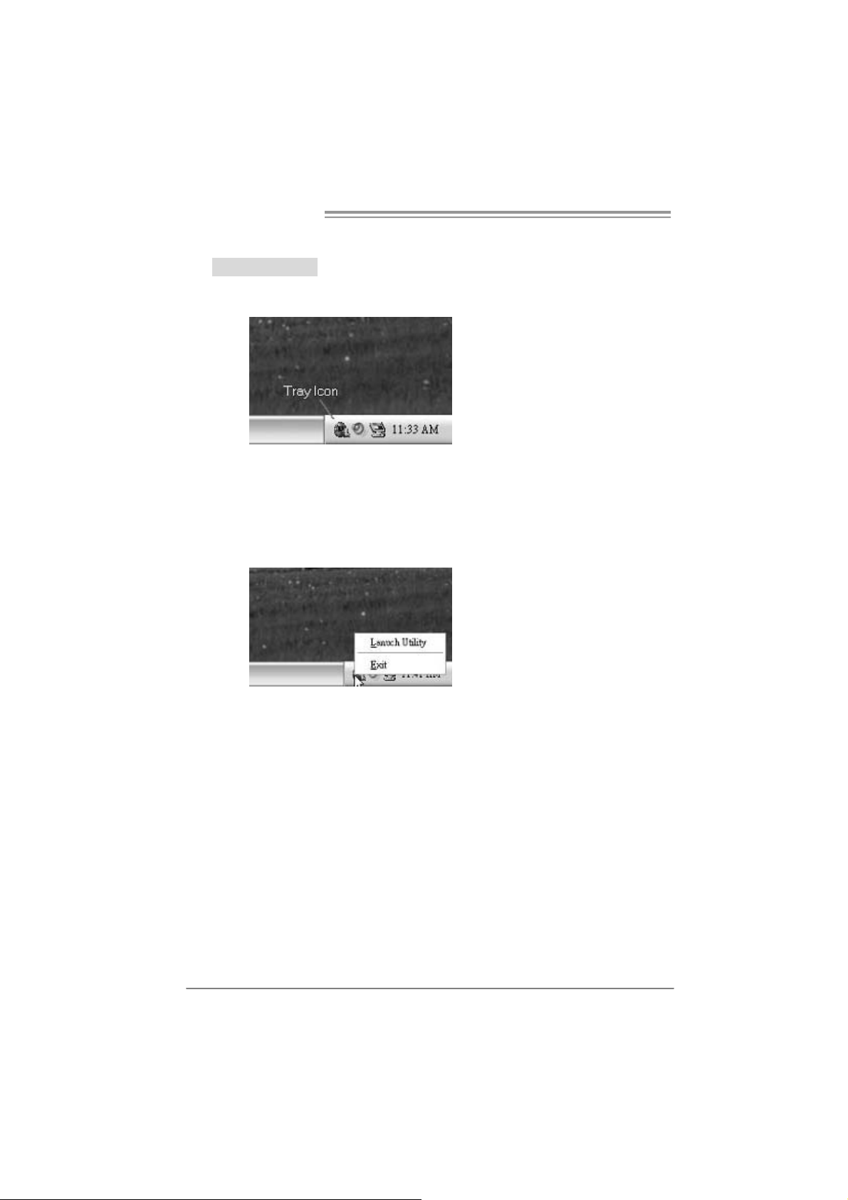
1. Tray Icon:
Whenever the Tray Icon utility is launched, it will display a little tra y
icon on the ri ght side of Windows Taskbar.
This utility is responsible for conveniently invoking [WarpSpeeder™]
Utility. You can use the mouse by clicki ng the left button i n order to
invoke [WarpSpeeder™] directly from the little tray i con or you can
ri ght-click the little tray icon to pop up a popup menu as following
figure. T he “Launch Utility” item in the popup menu has the same
functio n as mouse left-click on tray ic on and “Exit” ite m will cl ose
T ray Icon utility if sele cted.
26
Page 29

I945G-M7C
2. Main Panel
If y ou click the tray icon, [WarpS pe eder™] utility will be invoked.
Please refer to the follo wi ng fi gure; th e utility’s fi rst window you wi ll
see is Main Panel.
Main Panel con ta ins features as follows:
a. Di spl ay the CPU Speed, CPU exter na l clock, Memory clock, AGP cl ock,
and PCI clock information.
b. Contains About, Voltage, Overclock, and Hardware Monitor Buttons for
invoki ng respective panel s.
c. With a us er - f r iendly St atus Anim at io n, it c an represent 3 ov er c l ock
percentage stages:
Man walking→overclock percentage from 100% ~ 110 %
Panther running→overclock percentage from 110% ~ 120%
Ca r racing→overclock percentage from 120% ~ above
27
Page 30

Motherboard Manual
3. Vol ta ge Panel
Clic k the Vol ta ge bu tton in Main Pa nel, th e butt on will be highligh te d
and t he Vol ta ge Pa ne l will slide out to up a s the following figure .
In thi s panel, you can decide to increase CPU core voltage and
Memory voltage or not. The default setting is “No”. If yo u wa n t to get
the best performance of overclocking, we recommend you click the
option “Yes”.
28
Page 31

I945G-M7C
4. Over clock Panel
Clic k the Overcloc k button in Ma in Pa ne l, the bu tton will be
highlighted and the Overclock Panel will slide out to left as the
fol l owi ng f igur e.
Overclock Panel contains the these fea tures:
a. “–3MHz button”, “-1MHz button”, “+1MHz button”, and “+3MHz button”:
provide user the ability to do real -time overclock adjustment.
Warning:
Manually overclock is pot ent ially dangerous, espec ially when t he
overcl ocking perc entage is over 110 %. We st rongly rec ommend y ou
verify ev ery s peed y ou overclock by c lick the Verif y button. Or, you c an
just click Aut o ov erclock butt on and let [WarpSpeeder™] aut om at ic ally
gets the best res ult for you.
b. “Recovery Dialog button”: Pop up the following dialog. Let user select
a restoring way if system need to do a fail-safe reboot.
29
Page 32

Motherboard Manual
c. “Auto-overclock button”: User can click this button and
[Wa rpS pee der™] will set th e be st and sta ble perf ormance and
frequency automatically. [WarpSpeeder™] utility will execute a
series of testing until syste m fail. Then syst em will do fail-saf e
reboot by using Watchdog function. After reboot, the
[WarpSpeeder™] utility will restore to the hardware defaul t
setting or load the veri fied best and stabl e frequency according
to the Recovery Di alog’s setting.
d. “Verify button”: User can cli ck this button and [WarpSpeeder™]
will proceed a testi ng for current frequency. If the testing is ok,
then the curre n t frequency will be saved into system registry. If
the testing fail, system wil l do a fail-safe rebooti ng. After reboot,
the [WarpSpe ed er™] utility will resto re to the ha rdware def au lt
setting or load the veri fied best and stabl e frequency according
to the Recovery Di alog’s setting.
Note:
Becaus e the t esting program s, invoked in Aut o-ov erc lock and Verify,
include D irectDraw, D irec t 3D and DirectShow t ests , the Direct X 8.1 or
newer runtime library is required. And please make sure your display
card’s color depth is High c olor (16 bit ) or True color( 24/32 bit ) that is
required for Direct3D rendering.
5. Hardware Monitor Panel
Clic k the Hardware Moni to r bu tt on in Main Pa ne l, the bu tton will be
highlighted and the Hardware Monitor panel will slide out to left as
the fo l lowing f ig ur e.
In thi s panel, you can get the real-time status information of your
syste m. The informati on will be ref reshed every 1 second.
30
Page 33

I945G-M7C
6. About Panel
Click the “about” button in M ain Panel , the button will be highli ghted
and th e About Pa ne l w il l s l id e out to up as the fo l low in g f igur e.
In thi s panel, you can get model name and detail informati on i n hi nts
of all the chipset that are related to overclocking. You can also get
the mainboard’s BIOS model and the Version number of
[WarpSpeeder™] utility.
Note :
Because the overcl ock, overvoltage, and hardware moni tor features
are controlled by several separate chipset, [WarpSpeeder™] divide
these features to separate panel s. If one chipset is not on board, the
correlative butto n i n Main panel wil l be disabled, but will not in terfer e
other panels’ functions. This property can make [WarpSpeeder™]
utility more robust.
31
Page 34

Motherboard Manual
/
/
/
/
APPENDENCIES: SPEC IN OTHER LAN GUAGE
GERMAN
Ver 5.x Ver 6.x
LGA 77 5
Intel Core2Duo/ Pentium 4 / Pentium D /
CPU
FS B 533 / 800 / 1066 M Hz 533 / 800 / 1066 M Hz
Chipsatz
Super E/A
Arbeitsspeic
her
Grafi k
IDE
SATA II
LAN
Celeron D Prozessoren mit bis zu 3,8 GHz
Unterstützt Hyper-Thre ading / Execute
Dis abl e B it
Extende d Memor y 64 Tech nolog y
Int el 9 45G
Intel ICH7
ITE 871 2F
Biet et die häufig verwe ndete n alte n Su per
E/A-Funkt io nen.
Low Pin C ount-S c hnitt s t ell e
Umgebu ngs kontr olle,
Hardware-Überwachung
Lüfterdrehzahl-Controller
"Smart Guardian" -Fun ktion v on ITE
DDR2 DIMM-S tec kplätze x 4
Jeder DIMM unterstützt 256/512MB &
1GB DDR2.
Max. 4GB Ar beitsspeicher
Dual-Kanal D DR2 Speic hermodul
Unterstützt DDR2 400 / 533 / 667
registrierte DIMMs. ECC DIMMs werde n
nicht unterstützt.
Int el GM A 950
Max. 22 4MB gem ei nsam be nutz t er
Vi deos peic her
Integrierter ID E-Controller
Ultra DMA 33 / 6 6 / 100 B us M as ter-Modus
Unterstützt PIO-Modus 0~4,
Integrierter Serial ATA-Controller
Datent rans ferr at e bi s z u 3Gb/s
Konform mit der SATA-Spezifikation
Version 2. 0.
Realtek RTL 8110SC / RTL 8100C(optional)
10 / 1 00 / 1000 Mb/s A uto -Negotiation
(Gigabit-Ba ndbreite nur beim RTL 8110SC)
Halb-/ Vollduplex-Funktion
E nha nced I ntel Spee dStep®
32
LGA 77 5
Intel Core2Duo/ Pentium 4 / Pentium D /
Celeron D Prozessoren mit bis zu 3,8 GHz
Unterstützt Hyper-Thre ading / Execute
Dis abl e B it
Extende d Memor y 64 Tech nolog y
Int el 9 45G
Intel ICH7
ITE 871 2F
Biet et die häufig verwe ndete n alte n Su per
E/A-Funkt io nen.
Low Pin C ount-S c hnitt s t ell e
Umgebu ngs kontr olle,
Hardware-Überwachung
Lüfterdrehzahl-Controller
"Smart Guardian" -Fun ktion v on ITE
DDR2 DIMM-S tec kplätze x 4
Jeder DIMM unterstützt 256/512MB &
1GB DDR2.
Max. 4GB Ar beitsspeicher
Dual-Kanal D DR2 Speic hermodul
Unterstützt DDR2 400 / 533 / 667
registrierte DIMMs. ECC DIMMs werde n
nicht unterstützt.
Int el GM A 950
Max. 22 4MB gem ei nsam be nutz t er
Vi deos peic her
Integrierter ID E-Controller
Ultra DMA 33 / 6 6 / 100 B us M as ter-Modus
Unterstützt PIO-Modus 0~4,
Integrierter Serial ATA-Controller
Datent rans ferr at e bi s z u 3Gb/s
Konform mit der SATA-Spezifikation
Version 2. 0.
Realtek RTL 8110SC / RTL 8100C(optional)
10 / 1 00 / 1000 Mb/s A uto -Negotiation
(Gigabit-Ba ndbreite nur beim RTL 8110SC)
Halb-/ Vollduplex-Funktion
E nha nced I ntel Spee dStep®
Page 35

Ver 5.x Ver 6.x
Audio-Code
c
Onboard-An
schluss
Rückseiten-
E/A
Platinengr ö
ße.
OS-Unterst
ützung
AL C 888
7.1-K anal-Au di oausg abe
Unterstützt Intel High-Definition Audio
PCI-Steckplatz x2 PCI-Steckplatz x2
PCI Expr ess x16 Steckplatz x1 PCI Expr ess x16 Steckplatz x1 Steckplät ze
PCI Expr ess x 1-Steckplatz x1 PCI Expr ess x 1-Steckplatz x1
Diskettenlaufwerkanschluss x1 Diskettenlaufwerkanschluss x1
IDE-Anschluss x1 IDE-Anschluss x1
SATA-Anschluss x4 SATA-Anschluss x4
Fronttafelanschluss x1 Fronttafelanschluss x1
Front-Audioanschluss x1 Front-Audioanschluss x1
CD-IN-Anschluss x1 CD-IN-Anschluss x1
S/PDIF-Ausgangsanschluss x1 S/PDIF-Ausgangsanschluss x1
S/PDIF Eingangsanschluss ( optional) x1 S/PDIF Einga ngsanschluss ( optional) x1
CPU-Lüfter-Sockel x1 CPU-Lüfter-Sockel x1
System-Lüfter-Sockel x1 System-Lüfter-Sockel x1
"Gehä use o ffen"-S oc kel (optio nal) x1 "Gehä use o ffen"-S oc kel (optio nal) x1
"CMOS löschen"-Sockel x1 "CMOS löschen"-Sockel x1
USB-Anschluss x2 USB-Anschluss x2
Stromanschluss (24-polig) x1 Stromanschluss (24-polig) x1
Stromanschluss (4-polig) x1 Stromanschluss (4-polig) x1
PS/2-Tastatur x1
PS/2-Maus x1
Serieller Anschluss x1
Druckeranschluss x1
VGA-Anschluss x1
LAN-Anschluss x1
USB-Anschluss x4
Audioanschluss x6
244 mm (B) X 244 mm (L) 244 mm (B) X 244 mm (L)
Windows 2K / XP / VISTA
Biostar behält sich das Recht vor, ohne
Ankündigung die Unterstützung für ein
Betri ebss ys tem hinzuzufü gen od er z u
entfernen.
AL C 861V D
5.1-K anal-Au di oausg abe
Unterstützt Intel High-Definition Audio
PS/2-Tastatur x1
PS/2-Maus x1
Serieller Anschluss x1
Druckeranschluss x1
VGA-Anschluss x1
LAN-Anschluss x1
USB-Anschluss x4
Audioanschluss x3
Windows 2K / XP / VISTA
Biostar behält sich das Recht vor, ohne
Ankündigung die Unterstützung für ein
Betri ebss ys tem hinzuzufü gen od er z u
entfernen.
I945G-M7C
33
Page 36

Motherboard Manual
p
p
/
/
p
/
FRANCE
Ver 5.x Ver 6.x
LGA 77 5
Proces s eurs Intel Core 2Duo/ P entium 4 /
Pentium D / Celeron D jusqu'à 3,8 GHz
UC
Bus frontal 533 / 800 / 1066 M Hz 533 / 800 / 1066 M Hz
Chipset
Super E/S
Mémoire
principal e
Graphiques
IDE
SATA II
LAN
Prend en charge les technologies
Hyper -Thre adin g / d'ex écut ion de bit de
désactivation / Intel Spe edStep®
optimisée/ de mémoire ét e nd ue 64
Int el 9 45G
Intel ICH7
ITE 871 2F
Four nit la fo nc t ionnal i té de Super E/S
patrimoniales la plus utilisée.
Interface à faible compte de broc hes
Initiatives de contrôle e nvironnementales,
Monit eur de mat éri el
Contrôl eur de vites s e de ventil at eur
Fonction " Gardie n intelligent" de l'ITE
Fent es DDR 2 DIMM x 4
Chaque DIMM prend e n ch arge des DDR2
de 2 56/51 2 Mo et 1Go
Capacité mémoire maximale de 4 Go
Modul e de mém oire DDR 2 à mo de à do uble
voie
Prend en charge la DDR 2 400 / 53 3 / 667
Les DIMM à registres et DIMM avec code
correcteurs d'erreurs ne so nt
charge
Int el GM A 950
Mémoire vidéo partagée maximale de 224
Mo
Contrôl eur IDE intégr é
Mode pri nci pale de Bus Ultra DMA 3 3
100
Prend en charge le m ode PIO 0~4,
Contrôleur Serial ATA intégré :
Taux de transfert jusqu'à 3 Go/s.
Conforme à la spécification SATA Version
2.0
Realtek RTL 8110SC / RTL 8100C(optional)
10 / 1 00 / 10 00 Mb/s négoc iat io n
automatique (La ban de passante Giga bi t
est pour le RTL 8110SC uniq uement)
Half / Full duplex capability
as prises en
LGA 77 5
Proces s eurs Intel Core 2Duo/ P entium 4 /
Pentium D / Celeron D jusqu'à 3,8 GHz
Prend en charge les technologies
Hyper -Thre adin g / d'ex écut ion de bit de
désactivation / Intel Spe edStep®
optimisée/ de mémoire ét e nd ue 64
Int el 9 45G
Intel ICH7
ITE 871 2F
Four nit la fo nc t ionnal i té de Super E/S
patrimoniales la plus utilisée.
Interface à faible compte de broc hes
Initiatives de contrôle e nvironnementales,
Monit eur de mat éri el
Contrôl eur de vites s e de ventil at eur
Fonction " Gardie n intelligent" de l'ITE
Fent es DDR 2 DIMM x 4
Chaque DIMM prend e n ch arge des DDR2
de 2 56/51 2 Mo et 1Go
Capacité mémoire maximale de 4 Go
Modul e de mém oire DDR 2 à mo de à do uble
voie
Prend en charge la DDR 2 400 / 53 3 / 667
Les DIMM à registres et DIMM avec code
correcteurs d'erreurs ne so nt
charge
Int el GM A 950
Mémoire vidéo partagée maximale de 224
Mo
Contrôl eur IDE intégr é
Mode
66
ri ncipale de Bus Ultra DMA 33 / 66
100
Prend en charge le m ode PIO 0~4,
Contrôleur Serial ATA intégré :
Taux de transfert jusqu'à 3 Go/s.
Conforme à la spécification SATA Version
2.0
Realtek RTL 8110SC / RTL 8100C(optional)
10 / 1 00 / 10 00 Mb/s négoc iat io n
automatique (La ban de passante Giga bi t
est pour le RTL 8110SC uniq uement)
Half / Full duplex capability
as prises en
34
Page 37

Ver 5.x Ver 6.x
AL C 861V D
Sortie audio à 5.1 voies
Prise en c harge de l'au dio haut e définition
Intel
Connecteur d'entré e S/P DIF x1
(en option)
Embase d'ouverture de châssis x1
(en option)
Connecteur d'alimentatio n x1
(24 broches)
Connecteur d'alimentatio n x1
(4 broches)
Clavier PS/2 x1
Souris PS/2 x1
Port série x1
Port d' imprimante x1
Port VGA x1
Port LAN x1
Port USB x4
Fiche audio x3
Windows 2K / XP / VISTA
Biostar se réserve le droit d'ajouter ou de
supprimer le supp ort de S E avec o u sa ns
préavis.
Codec
audio
Connec t eu
r
embarqué
E/S d u
pann eau
arrière
Dim ens i on
s de la
carte
Suppor t
SE
AL C 888
Sortie audio à 7.1 voies
Prise en c harge de l'au dio haut e définition
Intel
Fente PCI x2 Fente PCI x2
Slot PCI Ex press x16 x1 Slot PCI Express x16 x1 Fentes
Slot PCI Ex pres s x 1 x1 Slot PCI Ex press x 1 x1
Connec teur de di s qu ette x1 Connecteur de di s qu ette x1
Connec t eur IDE x1 Connec t eur IDE x1
Connec t eur SATA x4 Connecteur SA TA x4
Connec t eur du pa nne au avant x1 C onnec t eur du pa nne au avant x1
Connec t eur Audio du p ann eau ava nt x1 Connec t eur Audio d u pann eau ava nt x1
Connecteur d'entré e CD x1 Connecteur d'entré e CD x1
Connecteur de sortie S/PDIF x1 Connecteur de sortie S/PDIF x1
Connecteur d'entré e S/P DIF x1
(en option)
Embas e d e ve ntilateur UC x1 Em bas e de ve nti lat eur UC x1
Embase de ventilateur système x1 Embase de ventilateur système x1
Embase d'ouverture de châssis x1
(en option)
Embas e d'e ff acement CM O S x1 Embas e d' e ffac em ent C MOS x1
Connec t eur USB x2 Connec t eur USB x2
Connecteur d'alimentatio n x1
(24 broches)
Connecteur d'alimentatio n x1
(4 broches)
Clavier PS/2 x1
Souris PS/2 x1
Port série x1
Port d' imprimante x1
Port VGA x1
Port LAN x1
Port USB x4
Fiche audio x6
244 mm (l) X 244 mm (H) 244 mm (l) X 244 mm (H)
Windows 2K / XP / VISTA
Biostar se réserve le droit d'ajouter ou de
supprimer le supp ort de S E avec o u sa ns
préavis.
I945G-M7C
35
Page 38

Motherboard Manual
p® /
/
pp
pp
ITALIAN
Ver 5.x Ver 6.x
LGA 77 5
Processore Intel Core2Duo/ Pentium 4 /
CPU
FS B 533 / 800 / 1066 M Hz 533 / 800 / 1066 M Hz
Chipset
Super I/O
Memoria
principal e
Grafica
IDE
SATA II
LAN
Pentium D / Celeron D fino a 3.8 GHz
Suppor to di Hyper -T hreadi ng / Execute
Disable Bit / E nhanced I ntel SpeedSte
Tec nolo gi a Extend ed Mem or y 64
Int el 9 45G
Intel ICH7
ITE 871 2F
Fornisce le funzio nalità legacy Super I/O
usate più comunemente.
Interfaccia LPC (L ow Pin Count)
Funzioni di controllo dell’ambiente:
Monitoraggio h ardware
Controller velocità ventolina
Funz i one "Sm art G uardi an" di I TE
Al loggi DIMM DDR 2 x 4
Ciascun DIMM su
1GB
Capacità massima della memoria 4GB
Modulo di mem oria DDR2 a can ale dop pio
Supporto di DDR2 400 / 533 / 667
DIMM registrati e DIMM ECC non sono
support at i
Int el GM A 950
La memoria video condivisa massima è di
224MB
Controller ID E i ntegrato
Modalità Bus Master Ultra DMA 33 / 66 /
100
Suppor to m odalità PIO M ode 0-4
Controller Serial ATA integrato
Veloc ità di t ras feri ment o dei dati fi no a 3
Gb/s .
Compatibile specifiche SATA Versione 2.0.
Realtek RTL 8110SC / RTL 8100C(optional)
Negoziazione automatica 10 / 100 / 100 0
Mb/s (la lar ghezza di ban da Gigabit è solo
per RTL 81 10S C )
Capacità Half / Full Duplex
ort a DDR 2 256/51 2MB e
36
LGA 77 5
Processore Intel Core2Duo/ Pentium 4 /
Pentium D / Celeron D fino a 3.8 GHz
Suppor to di Hyper -T hreadi ng / Execute
Dis abl e B it
Tec nolo gi a Extend ed Mem or y 64
Int el 9 45G
Intel ICH7
ITE 871 2F
Fornisce le funzio nalità legacy Super I/O
usate più comunemente.
Interfaccia LPC (L ow Pin Count)
Funzioni di controllo dell’ambiente:
Monitoraggio h ardware
Controller velocità ventolina
Funz i one "Sm art G uardi an" di I TE
Al loggi DIMM DDR 2 x 4
Ciascun DIMM su
1GB
Capacità massima della memoria 4GB
Modulo di mem oria DDR2 a can ale dop pio
Supporto di DDR2 400 / 533 / 667
DIMM registrati e DIMM ECC non sono
support at i
Int el GM A 950
La memoria video condivisa massima è di
224MB
Controller ID E i ntegrato
Modalità Bus Master Ultra DMA 33 / 66 /
100
Suppor to m odalità PIO M ode 0-4
Controller Serial ATA integrato
Veloc ità di t ras feri ment o dei dati fi no a 3
Gb/s .
Compatibile specifiche SATA Versione 2.0.
Realtek RTL 8110SC / RTL 8100C(optional)
Negoziazione automatica 10 / 100 / 100 0
Mb/s (la lar ghezza di ban da Gigabit è solo
per RTL 81 10S C )
Capacità Half / Full Duplex
E nha nced I ntel Spee dStep® /
ort a DDR 2 256/51 2MB e
Page 39

Ver 5.x Ver 6.x
Codec
audio
Connettori
su scheda
I/O
pannello
posteri ore
Dim ens i on
i scheda
Sistemi
operativi
support at i
AL C 888
Uscita audio 7.1 canali
Suppor to au dio High- Definit ion (HD ) Intel
Alloggio PCI x2 Alloggio PCI x2
Al loggio PCI Ex pres s x1 6 x1 Alloggio PCI Ex press x1 6 x1 Alloggi
Al loggio PCI Ex pres s x1 x1 A lloggi o PC I Express x1 x1
Connet t ore flo ppy x1 Connet t or e flo ppy x1
Connet tore IDE x1 Connet t or e IDE x1
Connet tore SATA x4 Connet t ore SATA x4
Connet t ore pannello fro ntale x1 Connet t ore pa nnel l o fro nt al e x1
Connettore audio frontale x1 Connettore audio frontale x1
Connettore CD-in x1 Connettore CD-in x1
Connettore output SPDIF x1 Connettore output SPDIF x1
Connettore input S/PDIF x1
(optional)
Collettore ventolina CPU x1 Collettore ventolina CPU x1
Collettore ventolina sistema x1 Collettore ventolina sistema x1
Collettore apertura telaio( optional) x1 Collettore apertura telaio( optional) x1
Collettore cancellazione CMO S x1 Collettore cancellazione CMOS x1
Connet tore USB x2 Connet t ore USB x2
Connettore alimentazione x1
(24 pin)
Connettore alimentazione x1
(4 pin)
Ta s t i e ra P S / 2 x 1
Mouse PS/2 x1
Porta seriale x1
Porta s tampante x1
Porta VGA x1
Porta LAN x1
Porta USB x4
Connet tore audio x6
24 4 m m (l argh ez z a) x 24 4 m m (altez z a) 24 4 mm (l ar gh ezz a) x 24 4 mm (al t ezza)
Windows 2K / XP / VISTA
Biostar si riserva il diritto di aggiungere o
rimuovere il supporto di qualsiasi sistema
operativo s e nz a pre avviso.
AL C 861V D
Uscita audio 5.1 canali
Suppor to au dio High- Definit ion (HD ) Intel
Connettore input S/PDIF x1
(optional)
Connettore alimentazione x1
(24 pin)
Connettore alimentazione x1
(4 pin)
Ta s t i e ra P S / 2 x 1
Mouse PS/2 x1
Porta seriale x1
Porta s tampante x1
Porta VGA x1
Porta LAN x1
Porta USB x4
Connet tore audio x3
Windows 2K / XP / VISTA
Biostar si riserva il diritto di aggiungere o
rimuovere il supporto di qualsiasi sistema
operativo s e nz a pre avviso.
I945G-M7C
37
Page 40

Motherboard Manual
SPANISH
Ver 5.x Ver 6.x
LGA 77 5
Procesador I ntel Core 2Duo/ P entium 4 /
Pentium D / Celeron D hasta 3,8 GHz
CPU
FS B 533 / 800 / 1066 M Hz 533 / 800 / 1066 M Hz
Conjunto
de chips
Súper E/S
Memoria
principal
Gráfi c os
IDE
SATA II
Red Local
Adm ite Hyper -T hreadi ng / Bi t d e
deshabilitación de ejecución / Intel
SpeedStep® Me jora do / Tecnologí a
Extende d Memor y 64
Int el 9 45G
Intel ICH7
ITE 871 2F
Le ofrece las funcionalidades heredadas de
uso más común Súper E/S.
Interfaz de cuenta Low Pin
Iniciativas de control de entor no,
Monitor hardware
Cont rolador de veloc ida d d e ve ntilador
Función "Guardia inteligente" de ITE
Ranuras DI MM DDR 2 x 4
Cada DIMM admit e DDR de 256/5 12MB y
1GB
Capacidad máxima de memoria de 4GB
Módul o de m emoria DDR 2 de canal Doble
Admite DDR2 de 400 / 533 / 667
No a dmite DIMM re gistrados o DIMM
compatibles con ECC
Int el GM A 950
Memoria máxima de ví deo compartida de
224MB
Controlador IDE inte grado
Modo bus maestro Ultra DMA 33 / 66 / 100
Soport e l os Mo dos PIO 0~4,
Controlador ATA Serie Integrado
Tasas de transferencia de hasta 3 Gb/s.
Compatible con la versión SATA 2.0.
Realtek RTL 8 110SC / RTL 8100C (o pcional)
Negociac ión de 10 / 100 / 100 0 M b /s (el
anc ho de ban da Gi ga bit es únic ame nt e para
811 0SC)
Funciones Half / Full dúplex
LGA 77 5
Procesador I ntel Core 2Duo/ P entium 4 /
Pentium D / Celeron D hasta 3,8 GHz
Adm ite Hyper -T hreadi ng / Bi t d e
deshabilitación de ejecución / Intel
SpeedStep® Me jora do / Tecnologí a
Extende d Memor y 64
Int el 9 45G
Intel ICH7
ITE 871 2F
Le ofrece las funcionalidades heredadas de
uso más común Súper E/S.
Interfaz de cuenta Low Pin
Iniciativas de control de entor no,
Monitor hardware
Cont rolador de veloc ida d d e ve ntilador
Función "Guardia inteligente" de ITE
Ranuras DI MM DDR 2 x 4
Cada DIMM admit e DDR de 256/5 12MB y
1GB
Capacidad máxima de memoria de 4GB
Módul o de m emoria DDR 2 de canal Doble
Admite DDR2 de 400 / 533 / 667
No a dmite DIMM re gistrados o DIMM
compatibles con ECC
Int el GM A 950
Memoria máxima de ví deo compartida de
224MB
Controlador IDE inte grado
Modo bus maestro Ultra DMA 33 / 66 / 100
Soport e l os Mo dos PIO 0~4,
Controlador ATA Serie Integrado
Tasas de transferencia de hasta 3 Gb/s.
Compatible con la versión SATA 2.0.
Realtek RTL 8 110SC / RTL 8100C (o pcional)
Negociac ión de 10 / 100 / 100 0 M b /s (el
anc ho de ban da Gi ga bit es únic ame nt e para
811 0SC)
Funciones Half / Full dúplex
38
Page 41

Ver 5.x Ver 6.x
p
Códecs de
sonido
Conectore
s en placa
Panel
trasero de
E/S
Ta m a ñ o d e
la placa
Soporte de
sistema
operativo
AL C 888
Salida de sonido de 7.1 canales
Soporte d e soni do I ntel d e Alt a Defi nic ión
Ranura PCI X2 Ranura PC I X2
Ranura PC I Ex pres s x1 6 X1 Ranura PCI Ex pr es s x1 6 X 1 Ranuras
Ranura PC I ex pres s x 1 X1 Ranura PCI ex pres s x 1 X1
Conector disco flexible X1 Conector disco flexible X1
Conector IDE X1 Conector IDE X1
Conector SATA X4 Conector SATA X4
Conector de panel fro ntal X 1 Conector de panel fro ntal X1
Conector de sonido frontal X1 Conector de sonido frontal X1
Conector de entra da de C D X1 Conector de entra da de C D X1
Conector de salida S/PDIF X1 Conector de salida S/PDIF X1
Conector de entra da S/PDIF x1
(opcional)
Cabecera d e ve nt ilador de C PU X1 Cabec era d e ve nt ilador de C PU X1
Cabecera d e ve nt ilador de
sistema X1
Cabecera de chasis abi erto(opcional) X 1 Cabecera de chasis abierto(opcional) X 1
Cabecera d e b orrado de CMO S X1 Cabec era d e borrado de C MO S X1
Conector USB X2 Conector USB X2
Conector de alimentación X1
(24 patillas)
Conector de alimentación X1
(4 patillas)
Te c l ad o PS /2 X 1
Ratón PS/2 X1
Puerto s erie X1
Puert o de impr es ora X1
Puerto VGA X1
Puert o de re d local X1
Puerto US B X4
Conector de sonido X6
244mm. (A) X 244 Mm. (H) 244mm . (A) X 244 Mm. (H)
Windows 2K / XP / VISTA
Biostar se reserva el derecho de a ñadir o
retirar el so
aviso previo.
orte de cualquier SO con o sin
AL C 861V D
Salida de sonido de 5.1 canales
Soporte d e soni do I ntel d e Alt a Defi nic ión
Conector de entra da S/PDIF x1
(opcional)
Cabecera d e ve nt ilador de
sistema X1
Conector de alimentación X1
(24 patillas)
Conector de alimentación X1
(4 patillas)
Te c l ad o PS /2 X 1
Ratón PS/2 X1
Puerto s erie X1
Puert o de impr es ora X1
Puerto VGA X1
Puert o de re d local X1
Puerto US B X4
Conector de sonido X3
Windows 2K / XP / VISTA
Biostar se reserva el derecho de a ñadir o
retirar el soporte de cualquier SO con o sin
aviso previo.
I945G-M7C
39
Page 42

Motherboard Manual
PORTUGUESE
Ver 5.x Ver 6.x
LGA 77 5
Processador Intel Core2Duo / Pentium 4 /
CPU
FS B 533 / 800 / 1066 M Hz 533 / 800 / 1066 M Hz
Chipset
Especificaç
ão Sup er
I/O
Memória
principal
Placa
gráfica
IDE
SATA II
LAN
Pentium D / Celeron D até 3,8 GHz
Suporta as tec nologias Hyper -Threa ding /
Execute Dis able Bit / E nhanced I ntel
SpeedStep® / E xtended Memor y 64
Int el 9 45G
Intel ICH7
ITE 871 2F
Proporciona as funcionalidades mais
utilizadas em termos da especificação
Super I/O.
Int erface LPC (Low Pi n Co unt).
Iniciativas para control o do am biente
Monitorização do hardware
Cont rolador da veloc ida de da v entoin ha
Função "Smart Guardia n" da I TE
Ranhuras DI MM D DR2 x 4
Cada mó dulo DIMM s u porta uma memóri a
DDR2 de 256/ 512 MB & 1 GB
Capacidade m áxim a de memória : 4 GB
Módulo de m em ór ia DDR 2 de canal duplo
Suporta módulos DDR2 400 / 533 / 667
Os módulos DIMM r egistados e os DIMM
ECC não são suportados
Int el GM A 950
Memória de vídeo máxima partilha da: 224
MB
Controlador IDE inte grado
Modo B us mas t er Ult r a DMA 33 / 66 / 10 0
Suporta o mod o PIO 0~4,
Controlador Serial ATA integrado
Velocidades de transmissão de dados até 3
Gb/s .
Compatibilidade com a especificação SATA
ver s ão 2. 0.
Realtek RTL 8 110SC / RTL 8100C (o pc ional)
Auto negociação de 10 / 100 / 1000 Mb/s (a
lar gura de ba n da Giga bi t r e fere- se apenas à
especificação RTL 8110SC)
Capacidade s emi/full- dupl ex
LGA 77 5
Processador Intel Core2Duo / Pentium 4 /
Pentium D / Celeron D até 3,8 GHz
Suporta as tec nologias Hyper -Threa ding /
Execute Dis able Bit / E nhanced I ntel
SpeedStep® / E xtended Memor y 64
Int el 9 45G
Intel ICH7
ITE 871 2F
Proporciona as funcionalidades mais
utilizadas em termos da especificação
Super I/O.
Int erface LPC (Low Pi n Co unt).
Iniciativas para control o do am biente
Monitorização do hardware
Cont rolador da veloc ida de da v entoin ha
Função "Smart Guardia n" da I TE
Ranhuras DI MM D DR2 x 4
Cada mó dulo DIMM s u porta uma memóri a
DDR2 de 256/ 512 MB & 1 GB
Capacidade m áxim a de memória : 4 GB
Módulo de m em ór ia DDR 2 de canal duplo
Suporta módulos DDR2 400 / 533 / 667
Os módulos DIMM r egistados e os DIMM
ECC não são suportados
Int el GM A 950
Memória de vídeo máxima partilha da: 224
MB
Controlador IDE inte grado
Modo B us mas t er Ult r a DMA 33 / 66 / 10 0
Suporta o mod o PIO 0~4,
Controlador Serial ATA integrado
Velocidades de transmissão de dados até 3
Gb/s .
Compatibilidade com a especificação SATA
ver s ão 2. 0.
Realtek RTL 8 110SC / RTL 8100C (o pc ional)
Auto negociação de 10 / 100 / 1000 Mb/s (a
lar gura de ba n da Giga bi t r e fere- se apenas à
especificação RTL 8110SC)
Capacidade s emi/full- dupl ex
40
Page 43

Ver 5.x Ver 6.x
Codec de
som
Ranhuras
Conectore
s na placa
Entradas/
Saídas no
painel
traseiro
Ta m a n h o
da pl aca
Sistemas
operativos
suportado
s
AL C 888
Saída de áudio de 7.1 ca nai s
Suporta a especificação Intel
High-Definition Audio
Ranhura PCI x2 Ranhura PCI x2
Ranhura PCI Expres s x 16 x1 R anhura PCI Express x 16 x1
Ranhura PCI Expres s x 1 x1 R anhur a PCI Express x 1 x1
Conector da unida de de
disquetes x1
Conector IDE x1 Conector IDE x1
Conector SATA x4 Conector SATA x4
Conector do pai nel fro nt al x1 C onec t or do painel fro ntal x1
Conector de áudio frontal x1 C onec t or de áudio fro nt al x1
Conect or para entrada de C Ds x1 Conector para e ntrada de C Ds x1
Conector de saída S/PDIF x1 Conector de saída S/PDIF x1
Conector de entra da S /P DIF ( opcion al) x 1 Conector de entra da S /P DIF ( opcion al) x 1
Conec t or da ve nt oi nh a da CPU x1 Conec tor da ve ntoinh a d a C PU x1
Conec t or da ve nt oi nh a do
sistema x1
Conector para detec ç ão da
abertura do chassis (opcional) x1
Conector para limpez a do C MOS x1 Conec tor para lim pez a do CMO S x1
Conector USB x2 Conector USB x2
Conector de alimentação x1
(24 pin os )
Conector de alimentação x1
(4 pinos)
Te c l ad o PS /2 x 1
Rato PS/2 x1
Porta série x1
Porta para impressora x1
Porta VGA x1
Porta LAN x1
Porta USB x4
Tomada de áu dio x6
24 4 m m (L) X 244 m m (A ) 244 m m (L) X 244 m m (A )
Windows 2K / XP / VISTA
A Biostar reserva-se o direito de adicionar
ou remov er suporte para qualq uer sistema
operativo c om ou s em aviso prévio.
AL C 861V D
Saída de áudio de 5.1 ca nai s
Suporta a especificação Intel
High-Definition Audio
Conector da unida de de
disquetes x1
Conec t or da ve nt oi nh a do
sistema x1
Conector para detec ç ão da
abertura do chassis (opcional) x1
Conector de alimentação x1
(24 pin os )
Conector de alimentação x1
(4 pinos)
Te c l ad o PS /2 x 1
Rato PS/2 x1
Porta série x1
Porta para impressora x1
Porta VGA x1
Porta LAN x1
Porta USB x4
Tomada de áu dio x3
Windows 2K / XP / VISTA
A Biostar reserva-se o direito de adicionar
ou remov er suporte para qualq uer sistema
operativo c om ou s em aviso prévio.
I945G-M7C
41
Page 44
Motherboard Manual
g /
p
p
POLISH
Ver 5.x Ver 6.x
LGA 77 5
Procesor Intel Cor e2D uo/ Penti um 4 /
Procesor
FS B 533 / 800 / 1066 M Hz 533 / 800 / 1066 M Hz
Chipset
Pamięć
główna
Super I/O
Grafika
IDE
SATA II
LAN
Pentium D / Celeron D do 3,8 GHz
Obsługa Hyper-T hreading / Exec ut e Dis able
Bit / Enhanced Intel SpeedStep® /
Extende d Memor y 64 Tech nolog y
Int el 9 45G
Intel ICH7
Gniaz da DDR 2 DIMM x 4
Każde gniazd o DIMM obsługuje moduły
256 /51 2MB oraz 1GB DDR 2
Maks. w ielkość pamięci 4GB
Moduł
amięci DDR2 z trybem podwójnego
kanału
Obsługa D DR2 40 0 / 5 33 / 66 7
Brak obsłu gi Registered DIMM or az ECC
DIMM
ITE 871 2F
Zapew ni a najbardziej pows z echne funkc je
Super I/O.
Interfejs L ow Pin Count
Funkcje kontr ol i warun ków prac y,
Monitor H/W
Kontroler prę dkości wentylatora
Funkcja ITE "Smart Guar dian"
Int el GM A 950
Maks. w ielkość współdzielonej pamięci
video wy nosi 2 24MB
Zi nt egrowany kontr ol er ID E
Ultra DMA 33 / 66 / 100 Tryb Bus Master
obsługa PIO tryb 0~ 4,
Zi nt egrowany kontrol er Serial ATA
Transfer danych do 3 Gb/s.
Zgodność ze specyfikacją SATA w wersji
2.0.
Realtek RTL 8110SC / RTL 8100C (opcja)
10 / 1 00 / 10 00 M b/s z automat yczną
negoc jac ją szybkości (Pasmo giga bitow e
wyłącznie dla R TL 8 110SC)
Działanie w trybie połowic z nego / pełnego
dupleksu
LGA 77 5
Procesor Intel Cor e2D uo/ Penti um 4 /
Pentium D / Celeron D do 3,8 GHz
Obsługa Hyper-T hreadin
Bit / Enhanced Intel SpeedStep® /
Extende d Memor y 64 Tech nolog y
Int el 9 45G
Intel ICH7
Gniaz da DDR 2 DIMM x 4
Każde gniazd o DIMM obsługuje moduły
256 /51 2MB oraz 1GB DDR 2
Maks. w ielkość pamięci 4GB
Moduł pami ęci DDR2 z trybem
kanału
Obsługa D DR2 40 0 / 5 33 / 66 7
Brak obsłu gi Registered DIMM or az ECC
DIMM
ITE 871 2F
Zapew ni a najbardziej pows z echne funkc je
Super I/O.
Interfejs L ow Pin Count
Funkcje kontr ol i warun ków prac y,
Monitor H/W
Kontroler prę dkości wentylatora
Funkcja ITE "Smart Guar dian"
Int el GM A 950
Maks. w ielkość współdzielonej pamięci
video wy nosi 2 24MB
Zi nt egrowany kontr ol er ID E
Ultra DMA 33 / 66 / 100 Tryb Bus Master
obsługa PIO tryb 0~ 4,
Zi nt egrowany kontrol er Serial ATA
Transfer danych do 3 Gb/s.
Zgodność ze specyfikacją SATA w wersji
2.0.
Realtek RTL 8110SC / RTL 8100C (opcja)
10 / 1 00 / 10 00 M b/s z automat yczną
negoc jac ją szybkości (Pasmo giga bitow e
wyłącznie dla R TL 8 110SC)
Działanie w trybie połowic z nego / pełnego
dupleksu
Exec ut e Dis able
odwójnego
42
Page 45

Ver 5.x Ver 6.x
Kodek
dźwiękowy
Gniazda
Złącza
wbudowan
e
Back Panel
I/O
Wymiary
płyty
Obsluga
systemu
operacyjn
ego
AL C 888
7.1 ka nałowe w y jście audio
Obsługa Intel High-Definition Audi o
Gniazdo PCI x2 Gni az do PCI x2
Gniazdo PCI Express x16 x1 Gniazdo PCI Express x16 x1
Gniazdo PCI Express x 1 x1 Gniazdo PCI Express x 1 x1
Złącze napędu dyskietek x1 Złącze napędu dyskietek x1
Złącze IDE x1 Złącze IDE x1
Złącze SATA x4 Złącze SATA x4
Złącze panela przed niego x1 Z łącze panel a przed niego x1
Przednie złącz e a udio x1 Przednie złącze audio x1
Złącze wejścia CD x1 Złącze wejścia CD x1
Złącze wyjścia S/PDIF x1 Złącze wyjścia S/PDIF x1
Złącze wejścia S/PDIF (opcja) x1 Złącze wejścia S/PDIF (opcja) x1
Złącze główkow e w entylatora proces ora x1 Złącze główkow e w entylatora proces ora x1
Złącze główkowe wentylatora
systemowego x1
Złącze główkow e otwarc ia
obudow y (o pcja) x1
Złącze główkowe kas owani a
CMOS x1
Złącze USB x2 Złącze USB x2
Złącze z asil ani a (2 4 pi now e) x1 Złąc z e zas ilania (2 4 pi now e) x1
Złącz e zasilania (4 pin ow e) x1 Złącz e zasilania (4 pinowe) x1
Klawiatura PS/2 x1
Mysz PS/2 x1
Port szeregowy x1
Port druk arki x1
Port VGA x1
Port LAN x1
Port USB x4
Gniazdo audio x6
24 4 m m (S) X 244 m m (W) 24 4 mm (S) X 24 4 mm (W)
Windows 2K / XP / VISTA
Bi os t ar zas trz ega sobie prawo do dawania
lub odwoływania obsługi dowolnego
systemu operacyj nego bez pow iad omieni a.
AL C 861V D
5.1 ka nałowe w y jście audio
Obsługa Intel High-Definition Audi o
Złącze główkowe wentylatora
systemowego x1
Złącze główkow e otwarc ia
obudow y (o pcja) x1
Złącze główkowe kas owani a
CMOS x1
Klawiatura PS/2 x1
Mysz PS/2 x1
Port szeregowy x1
Port druk arki x1
Port VGA x1
Port LAN x1
Port USB x4
Gniazdo audio x3
Windows 2K / XP / VISTA
Bi os t ar zas trz ega sobie prawo do dawania
lub odwoływania obsługi dowolnego
systemu operacyj nego bez pow iad omieni a.
I945G-M7C
43
Page 46

Motherboard Manual
g /
g /
/
/
/
ф
ф
RUSSIAN
Ver 5.x Ver 6.x
LGA 77 5
CPU
(централь
ны й
проц ессор
)
FS B 533 / 800 / 1066 МГц 533 / 800 / 10 66 МГц
Набор
микросхе
м
Основная
память
Super I/O
Графика
IDE
SATA II
Процессор Intel Core 2Duo/ Pe nti um 4 /
Pentium D / Celeron D до 3.8 ГГц
Подде ржка техн оло гий Hyper-Threadin
Execute Dis able Bit / E nhanced I ntel
SpeedStep® / E xtended Memor y 64
Tec hnol ogy
Int el 9 45G
Intel ICH7
Слоты DDR2 DIMM x 4
Каждый модуль DIMM по ддерж ивае т
256 /51 2МБ & 1ГБ DDR2
Максимальн ая ёмк ость памя ти 4 ГБ
Модуль пам я ти с двухкан альным
реж имом DDR2
Подде ржка DDR2 400 / 533 / 667
Не подде рж ивае т за рег ис тр иров ан ны е
модули DIMM and ECC DIMM
ITE 871 2F
Обес печивает на ибо лее ис по льз уемы е
действ ую щие функциональные
возможности Super I/O.
Интерф ейс с низким количеством
выводов
Иниц иа ти вы по охр ане ок руж ающей
среды,
Аппара тны й монитор
Регуля тор скор ос ти
Функция IT E "Smart Gu ardian "
(Интелле ктуа ль на я защита)
Int el GM A 950
Максимальн ая совместно исп ользуема я
видео память составляет 224 МБ
Вс троенное устройство управления
вс трое нны м и ин те рф е йсам и устр ойств
Режим " хозяи на" шины Ultra DMA 33 / 66
100
Подде ржка режима PIO 0~ 4,
Вс троенное посл едов ательное
устройство упр авле ни я ATA
скорос ть пер едач и дан ных до 3
гига би т/с.
Соотве тс тв ие специ
2.0.
икац и и SATA версия
44
LGA 77 5
Процессор Intel Core 2Duo/ Pe nti um 4 /
Pentium D / Celeron D до 3.8 ГГц
Подде ржка техн оло гий Hyper-Threadin
Execute Dis able Bit / E nhanced I ntel
SpeedStep® / E xtended Memor y 64
Tec hnol ogy
Int el 9 45G
Intel ICH7
Слоты DDR2 DIMM x 4
Каждый модуль DIMM по ддерж ивае т
256 /51 2МБ & 1ГБ DDR2
Максимальн ая ёмк ость памя ти 4 ГБ
Модуль пам я ти с двухкан альным
реж имом DDR2
Подде ржка DDR2 400 / 533 / 667
Не подде рж ивае т за рег ис тр иров ан ны е
модули DIMM and ECC DIMM
ITE 871 2F
Обес печивает на ибо лее ис по льз уемы е
действ ую щие функциональные
возможности Super I/O.
Интерф ейс с низким количеством
выводов
Иниц иа ти вы по охр ане ок руж ающей
среды,
Аппара тны й монитор
Регуля тор скор ос ти
Функция IT E "Smart Gu ardian "
(Интелле ктуа ль на я защита)
Int el GM A 950
Максимальн ая совместно исп ользуемая
видео память составляет 224 МБ
Вс троенное устройство управления
вс трое нны м и ин те рф е йсам и устр ойств
Режим " хозяи на" шины Ultra DMA 33
100
Подде ржка режима PIO 0~ 4,
Вс троенное посл едов ательное
устройство упр авле ни я ATA
скорос ть пер едач и дан ных до 3
гига би т/с.
Соотве тс тв ие специ
2.0.
66
икац и и SATA версия
Page 47

Ver 5.x Ver 6.x
Локальна
я сеть
Звуковой
кодек
Слоты
Встроенн
ый разъём
Задн яя
пане ль
средств
ввода-вы
вода
Размер
пане ли
Подде ржк
а OS
Realtek RTL 8110SC /
RTL 81 00C (до пол нитель но)
Автоматическое согласова ние 10 / 100 /
100 0 Мб/с (гигабитная п ропус кная
способнос ть тольк о для гиг аби тн ого
физического уровня)
Частич ная / полная дуп лекс на я
способнос ть
AL C 888
Звуковая поддержка I ntel High-Defi nition
7.1кана льны й звуков ой вы ход
Слот PCI x2 Слот PCI x2
Слот PCI Express x16 x1 Слот PCI Express x16 x1
Слот PCI Ex press x 1 x1 Слот PCI Ex press x 1 x1
Разъём НГМД x1 Разъём НГМД x1
Разъём IDE x1 Раз ъём ID E x1
Разъём SATA x4 Разъём SATA x4
Разъём на лиц ево й пане ли x1 Раз ъём на лиц ево й пане ли x1
Входной звук овой раз ъём x1 Входной з вук овой раз ъём x1
Разъём ввода дл я CD x1 Раз ъём ввода для CD x1
Разъём выво да для S/PDIF x1 Разъём выво да для S/PDIF x1
Разъём ввода дл я S/PDIF
(допо лн ите ль но ) x1
Контак тирующее п рис посо бле ние
вентилятора ц ент раль ного процессора x1
Контак тирующее п рис посо бле ние
вентилятора системы x1
Шасси открытого контактирующего
прис пос обл е ни я(до по лни тель но) x1
Открытое контак тирующее
прис пос обл е ни е CMOS x1
USB-разъём x2 USB-разъём x2
Разъем пит ан ия (24 вывод ) x1 Разъем пит ан ия (24 вывод ) x1
Разъем пит ан ия (4 вы вод) x1 Разъем пит а н ия (4 вывод) x1
Клавиатура PS/ 2 x1
Мышь PS/2 x1
Последо вате льный по рт x1
Порт подключения пр инт ера x1
Порт VGA x1
Порт LAN x1
USB-порт x4
Гнездо для по дключ ени я
наушников x6
24 4 мм (Ш) X 244 мм (В) 24 4 мм (Ш) X 244 мм (В)
Windows 2K / XP / VISTA
Biostar сохраняет за собой прав о
добав лять или удалять средства
обес пече ни я для OS с ил и без
пред вар ите льно го уведомления.
Realtek RTL 8110SC /
RTL 81 00C (до пол нитель но)
Автоматическое согласова ние 10 / 100 /
100 0 Мб/с (гигабитная п ропус кная
способнос ть тольк о для гиг аби тн ого
физического уровня)
Частич ная / полная дуп лекс на я
способнос ть
AL C 861V D
Звуковая поддержка I ntel High-Defi nition
5.1кана льны й звуков ой вы ход
Разъём ввода дл я S/PDIF
(допо лн ите ль но ) x1
Контак тирующее п рис посо бле ние
вентилятора ц ент раль ного пр оц ес с ора x1
Контак тирующее п рис посо бле ние
вентилятора системы x1
Шасс и открытого контактирующего
прис пос обл е ни я(до по лни тель но) x1
Открытое контак тирующее
прис пос обл е ни е CMOS x1
Клавиатура PS/ 2 x1
Мышь PS/2 x1
Последо вате льный по рт x1
Порт подключения пр инт ера x1
Порт VGA x1
Порт LAN x1
USB-порт x4
Гнездо для по дключ ени я
наушников x3
Windows 2K / XP / VISTA
Biostar сохраняет за собой прав о
добав лять или удалять средства
обес пече ни я для OS с ил и без
пред вар ите льно го уведомления.
I945G-M7C
45
Page 48

Motherboard Manual
/
/
ARABIC
LGA 77 5
تﺎﺠﻟﺎﻌﻡIntel Core2Duo/ Pe ntium 4 / Pentium
D / C eler on D ﺑ ددﺮﺘ ﻳ ﻰﻟإ ﻞﺼ8.3 ﺰﺕﺮه ﺎﺠﻴﺝ
تﺎﻴﻨﻘﺕ ﻢﻋ ﺪﺕ Hyper -Thre ading / Exec ut e Dis able
En hanc e d I ntel Spee dStep® /
Bit
Extende d Memor y 64 Tech nolog y
ددﺮﺕ 533 / 800 /10 66 ﺰﺕﺮه ﺎﺠﻴﻡ
Int el 9 45G
Intel ICH7
ﻢﻋﺪﺕ ﻞآ ﺔﺤﺘﻓ DIMM ﻢﻋﺪﺕ ةﺮآاذ ﻦﻡ عﻮﻥ DDR2 ﺔﻌﺱ
256/512 ﺎﺠﻴﻡ ﺖﻳﺎﺑ و1 ﺎﺠﻴﺝ ﺖﻳ ﺎﺑ
ةﺪﺣو ةﺮآ اذ DDR2 ﺔﺝودﺰﻡ ةﺎ ﻨﻘﻟا
ﻢﻋﺪﺕ ةﺮآاﺬﻟا ﻦﻡ عﻮﻥ DDR2 تﺎﻌﺱ 400 / 53 3 / 6 67
ةﺮآاﺬﻟا ﻖﺋﺎﻗر ﻢﻋﺪﺕ ﻻDIMM ﻊﻡ ﻖﻓاﻮﺘﺕ ﻻ ﻲﺘﻟا ﻚﻠﺕو ECC
ITE 871 2F
ﺮﻓﻮﺕ ﺔﻔﻴﻇو Super I/O ﺮﺜ آﻷا ًﺎﻡاﺪﺨﺘﺱا.
ﺕﻢﻋ ﺪ ﺔﻴﻨﻘﺕ Low Pin Count Interface
ﺔﻔﻴﻇو "Smart Guar dian" ﻦﻡ ITE
Int el GM A 950
ﺔآﺮﺘﺸﻤﻟا ﻮﻳﺪﻴﻔﻟا ةﺮآاﺬﻟ ﺔﻌﺱ ﻰﺼﻗأ224ﺖﻳ ﺎ ﺑ ﺎﺠﻴﻡ
ﻢﻜﺤﺘﻡ IDE ﻞﻡﺎﻜﺘﻡ
ﺔﻴﻨﻘﺘﺑ ﻞﻗﺎ ﻥ Ultra DMA 33 / 66 / 10 0
ﻊﺿو ﻢﻋدPIO Mode 0~ 4
ﻢﻜﺤﺘﻡ Serial ATA ﻞﻡﺎ ﻜ ﺘ ﻡ
ﺔﻘﺑﺎﻄﻡ تﺎﻔﺹاﻮﻤﻟ SATA راﺪﺹﻹا 2. 0 .
تﺎﺠﻟﺎﻌﻡIntel Core2Duo/ Pe ntium 4 / Pentium
D / C eler on D ﺑ ددﺮﺘ ﻳ ﻰﻟإ ﻞﺼ8.3 ﺰﺕﺮه ﺎﺠﻴﺝ
تﺎﻴﻨﻘﺕ ﻢﻋ ﺪﺕ Hyper -Thre ading / Exec ut e Dis able
Bit / En hanc e d I ntel Spee dStep®
Extende d Memor y 64 Tech nolog y
ددﺮﺕ 533 / 800 /10 66 ﺰﺕﺮه ﺎﺠﻴﻡ
ﺔﺤﺘ ﻓDDR2 DIMM دﺪﻋ4
ﻢﻋﺪﺕ ﻞآ ﺔﺤﺘﻓ DIMM ﻢﻋﺪﺕ ةﺮآاذ ﻦﻡ عﻮﻥ DDR2 ﺔﻌﺱ
256/512 ﺎﺠﻴﻡ ﺖﻳﺎﺑ و1 ﺎﺠﻴﺝ ﺖﻳ ﺎﺑ
ﺔﻌﺱ ةﺮآاذ ىﻮﺼﻗ 4 ﺎﺠﻴﺝ ﺖﻳ ﺎ ﺑ
ةﺪﺣو ةﺮآ اذ DDR2 ﺔﺝودﺰﻡ ةﺎ ﻨﻘﻟا
ﻢﻋﺪﺕ ةﺮآاﺬﻟا ﻦﻡ عﻮﻥ DDR2 تﺎﻌﺱ 400 / 53 3 / 6 67
ﺎﺠﻴﻡ ﺖﻳ ﺎﺑ
ةﺮآاﺬﻟا ﻖﺋﺎﻗر ﻢﻋﺪﺕ ﻻDIMM ﻊﻡ ﻖﻓاﻮﺘﺕ ﻻ ﻲﺘﻟا ﻚﻠﺕو ECC
ﺮﻓﻮﺕ ﺔﻔﻴﻇو Super I/O ﺮﺜ آﻷا ًﺎﻡاﺪﺨﺘﺱا.
ﺕﻢﻋ ﺪ ﺔﻴﻨﻘﺕ Low Pin Count Interface
ﻞﺋﺎﺱو ﻢﻜﺤﺘﻟا ﻲﻓ ﺔﺌﻴﺒﻟا:
ﺐﻗاﺮﻡ ﺔﻓﺮﻌﻤﻟ ﺔﻟﺎﺣ ةﺰﻬﺝﻷا
ﺐﻗاﺮﻡ ﻲﻓ ﺔﻋﺮﺱ ﺔﺣوﺮﻤﻟا
ﺔﻔﻴﻇو"Smart Guar dian" ﻦﻡ ITE
Intel GMA 950
ﺔآﺮﺘﺸﻤﻟا ﻮﻳﺪﻴﻔﻟا ةﺮآاﺬﻟ ﺔﻌﺱ ﻰﺼﻗأ224ﺖﻳ ﺎ ﺑ ﺎﺠﻴﻡ
ﺔﻴﻨﻘﺘﺑ ﻞﻗﺎ ﻥ Ultra DMA 33 / 66 / 10 0
ﻊﺿو ﻲﺴﻴﺋر
ﻊﺿو ﻢﻋدPIO Mode 0~4
ﻢﻜﺤﺘﻡ Serial ATA ﻞﻡﺎ ﻜ ﺘ ﻡ
ﻞﻘﻥ تﺎﻥﺎﻴﺒﻟا تﺎﻋﺮﺴﺑ ﻞﺼﺕ ﻰﻟإ 3 ﺑﺎﺠﻴﺝﺖ/ﺔﻴﻥﺎﺙ.
ﺔﻘﺑﺎﻄﻡ تﺎﻔﺹاﻮﻤﻟ SATA راﺪﺹﻹا 2. 0 .
LGA 775
Int el 9 45G
Intel ICH7
ﺔﺤﺘ ﻓDDR2 DIMM دﺪﻋ4
ﺎﺠﻴﻡ ﺖﻳ ﺎﺑ
ITE 871 2F
ﻞﺋﺎﺱو ﻟاﻢﻜﺤ ﺘ ﻲﻓ ﺔﺌﻴﺒﻟا:
ﺐﻗاﺮﻡ ﺔﻓﺮﻌﻤﻟ ﺔﻟﺎﺣ ةﺰﻬﺝﻷا
ﺐﻗاﺮﻡ ﻲﻓ ﺔﻋﺮﺱ ﺔﺣوﺮﻤﻟا
ﻢﻜﺤﺘﻡ IDE ﻞﻡﺎﻜﺘﻡ
ﻊﺿو ﻲﺴﻴﺋر
ﺔﻌﺱ ةﺮآاذ ىﻮﺼﻗ 4 ﺎﺠﻴﺝ ﺖﻳ ﺎ ﺑ
ﻞﻘﻥ تﺎﻥﺎﻴﺒﻟا تﺎﻋﺮﺴﺑ ﻞﺼﺕ ﻰﻟإ 3 ﺖﺑﺎﺠﻴﺝ/ﺔﻴﻥﺎﺙ.
Ver 5.x Ver 6.x
ةﺪﺣو ﺔﺠﻟﺎﻌﻤﻟا
ﺔ ﻳ ﺰآ ﺮﻤﻟا
ﻞﻗﺎﻨﻟا ﻲﻡﺎﻡﻷا
ﻲﺒﻥﺎﺠﻟا
ﺔﻋﻮﻤﺠﻡ ﺢﺋاﺮﺸﻟا
ةﺮآاﺬ ﻟا ﺔﻴﺴﻴﺋﺮﻟا
Super I/O
تﺎ ﻡ ﻮ ﺱ ﺮ ﻟا ﺔﻗﺎﻄﺑ
ﺬﻔﻨ ﻡ IDE
SATA II
46
Page 49

Realtek RTL 8110SC /
RTL 81 00C )يرﺎﻴﺘﺥا(
ﻰﻠﻋ ﻂﻘ ﻓ رﻮﺼﻘﻡ ﺖﺑﺎﺠﻴﺠﻠﻟ يدد ﺮﺘﻟا قﺎﻄﻨﻟاRTL 8110SC
ﻞﻡﺎﻜﻟا جودﺰﻤﻟا ﻞﻘﻨﻟا ﺔﻴﻥﺎﻜﻡإ/ﻲﻔﺼﻨﻟا
5.1 اﻮﻨ ﻗت جﺮﺨﻟ تﻮﺼﻟا
ﻦﻡ ﻒﻳﺮﻌﺘﻟا ﻲﻟﺎﻋ تﻮﺼﻟا ﺔﻴﻨﻘﺕ ﻢﻋﺪﺕ Intel
ﺔﻴﻠ ﺤﻡ لﺎ ﺼ ﺕا ﺔﻜ ﺒ ﺵ ﺬﻔﻨﻡ دﺪﻋ1
Windows 2K / XP / VISTA
ﻆﻔﺘﺤﺕ Biostar ﺎﻬﻘﺤﺑ ﻲﻓ ﺔﻓﺎﺿإ وأ ﺔﻟازإ ﻢﻋﺪﻟا يﻷ مﺎﻈﻥ
ﻲﺋﺎ ﻘﻠﺕ ضوﺎﻔﺕ10/100 ﺖﻳﺎﺑ ﺎﺠﻴﻡ /و ﺔﻴﻥﺎﺙ1ﺖﺑ ﺎﺠﻴﺝ/ﺔﻴ ﻥﺎ ﺙ
ﻰﻠﻋ ﻂﻘ ﻓ رﻮﺼﻘﻡ ﺖﺑﺎﺠﻴﺠﻠﻟ يدد ﺮﺘﻟا قﺎﻄﻨﻟاRTL 8110SC
AL C 861V D
ﺢﻴﺕﺎﻔﻡ ﺔﺣ ﻮﻟPS/2 دﺪﻋ1
سوﺎﻡ PS/2 دﺪﻋ1
ﻲﻠﺴﻠﺴﺕ ﺬﻔﻨﻡ دﺪﻋ1
ﺔﻌﺑ ﺎﻃ ﺬﻔﻨﻡ دﺪﻋ1
ﺬﻔﻨﻡV GA دﺪﻋ1
ﺬﻓﺎﻨ ﻡUSB دﺪﻋ4
تﻮﺹ ﺲﺒﻘﻡ دﺪﻋ3
ﻆﻔﺘﺤﺕ Biostar ﺎﻬﻘﺤﺑ ﻲﻓ ﺔﻓﺎﺿإ وأ ﺔﻟازإ ﻢﻋﺪﻟا يﻷ مﺎﻈﻥ
ﻞﻴﻐﺸﺕ رﺎ ﻄﺥ ﺈ ﺑ وأ نوﺪﺑ رﺎ ﻄﺥ إ.
I945G-M7C
Realtek RTL 8110SC /
RTL 81 00C )يرﺎﻴﺘﺥا(
ﻲﺋﺎ ﻘﻠﺕ ضوﺎﻔﺕ10/100 ﺖﻳﺎﺑ ﺎﺠﻴﻡ /و ﺔﻴﻥﺎﺙ1ﺖﺑ ﺎﺠﻴﺝ/ﺔﻴ ﻥﺎ ﺙ
ﻞﻡﺎﻜﻟا جودﺰﻤﻟا ﻞﻘﻨﻟا ﺔﻴﻥﺎﻜﻡإ/ﻲﻔﺼﻨﻟا
AL C 888
7.1 تاﻮﻨﻗ جﺮﺨﻟ تﻮﺼﻟا
ﻦﻡ ﻒﻳﺮﻌﺘﻟا ﻲﻟﺎﻋ تﻮﺼﻟا ﺔﻴﻨﻘﺕ ﻢﻋﺪﺕ Intel
ﺔﺤﺘ ﻓPCI دﺪﻋ2 ﺔﺤﺘ ﻓPCI دﺪﻋ2
ﺔﺤﺘ ﻓx16 PCI Express دﺪﻋ1 ﺔﺤﺘ ﻓx16 PCI Express دﺪﻋ1 تﺎﺤﺘﻔﻟا
ﺔﺤﺘ ﻓPCI Express x 1 دﺪﻋ1 ﺔﺤﺘ ﻓPCI Express x 1 دﺪﻋ1
ﺔﻥﺮ ﻡ صاﺮﻗأ كﺮﺤﻡ ﺬﻔﻨﻡ دﺪﻋ1 ﻨﻡﺔﻥﺮ ﻡ صاﺮﻗأ كﺮﺤﻡ ﺬﻔ دﺪﻋ1
ﺬﻔﻨﻡIDE دﺪﻋ1 ﺬﻔﻨﻡIDE دﺪﻋ1
ﺬﻔﻨﻡSATA دﺪﻋ4 ﺬﻔﻨﻡSATA دﺪﻋ4
ﺔﻴ ﻡﺎ ﻡﻷ ا ﺔﺣﻮﻠﻟا ﺬﻔﻨﻡ دﺪﻋ1 ﺔﻴ ﻡﺎ ﻡﻷا ﺔﺣﻮﻠﻟا ﺬﻔﻨﻡ دﺪﻋ1
ﻲﻡﺎﻡﻷا تﻮﺼﻟا ﺬﻔﻨﻡ دﺪﻋ1 ﻲﻡﺎ ﻡﻷا تﻮﺼﻟا ﺬﻔﻨﻡ دﺪﻋ1
ﺬﻔﻨﻡCD-IN دﺪﻋ1 ﺬﻔﻨﻡCD-IN دﺪﻋ1
جﺮﺥ ﺬﻔﻨﻡS/PD IF دﺪﻋ 1 جﺮﺥ ﺬﻔﻨﻡS/PDI F دﺪﻋ1
ﻞﺥد ﺬﻔﻨﻡS/P DIF) ير ﺎ ﻴﺘ ﺥا( دﺪﻋ1 ﻞﺥد ﺬﻔﻨﻡS/P DIF) ير ﺎ ﻴﺘ ﺥا( دﺪﻋ1
ﺔﻳﺰآ ﺮ ﻤﻟ ا ﺔﺠﻟﺎﻌﻤﻟا ةﺪﺣو ﺔﺣوﺮ ﻡ ﺔﻠﺹو دﺪﻋ1 ﺔﻳﺰآ ﺮ ﻤﻟ ا ﺔﺠﻟﺎﻌﻤﻟا ةﺪﺣو ﺔﺣوﺮ ﻡ ﺔﻠﺹو دﺪﻋ1
مﺎﻈﻨﻟا ﺔﺣوﺮﻡ ﺔﻠﺹو دﺪﻋ1 مﺎﻈﻨﻟا ﺔﺣ وﺮ ﻡ ﺔﻠﺹو دﺪﻋ1
ﻞﻜﻴ ﻬﻟ ا ﺢﺘﻓ ﺔﻠﺹو)ير ﺎﻴ ﺘﺥ ا( دﺪﻋ1 ﻞﻜﻴ ﻬﻟ ا ﺢﺘﻓ ﺔﻠﺹو)ير ﺎﻴ ﺘﺥ ا( دﺪﻋ1
ﺢﺴﻡ ﺔﻠﺹوCMOS دﺪﻋ1 ﺢﺴﻡ ﺔﻠﺹوCMOS دﺪﻋ1
ﺬﻔﻨﻡUSB دﺪﻋ2 ﺬﻔﻨﻡUSB دﺪﻋ2
ﺔﻗﺎﻄﻟا ﻞﻴﺹﻮﺕ ﺬﻔﻨﻡ)24سﻮﺑد( دﺪﻋ1 ﺔﻗﺎﻄﻟا ﻞﻴﺹﻮﺕ ﺬﻔﻨﻡ)24سﻮﺑد( دﺪﻋ1
ﺔﻗﺎﻄﻟا ﻞﻴﺹﻮﺕ ﺬﻔﻨﻡ)4ﺲ ﻴﺑﺎﺑد( دﺪﻋ1 ﺔﻗﺎﻄﻟا ﻞﻴﺹﻮﺕ ﺬﻔﻨﻡ)4ﺲ ﻴﺑﺎﺑد( دﺪﻋ1
ﺢﻴﺕﺎﻔﻡ ﺔﺣ ﻮﻟPS/2 دﺪﻋ1
سوﺎﻡ PS/2 دﺪﻋ1
ﻲﻠﺴﻠﺴﺕ ﺬﻔﻨﻡ دﺪﻋ1
ﺔﻌﺑ ﺎﻃ ﺬﻔﻨﻡ دﺪﻋ1
ﺬﻔﻨﻡV GA دﺪﻋ1
ﺔﻴﻠ ﺤﻡ لﺎ ﺼ ﺕا ﺔﻜ ﺒ ﺵ ﺬﻔﻨﻡ دﺪﻋ1
ﺬﻓﺎﻨ ﻡUSB دﺪﻋ4
تﻮﺹ ﺲﺒﻘﻡ دﺪﻋ6
Windows 2K / XP / VIS TA
ﻞﻴﻐﺸﺕ رﺎ ﻄﺥ ﺈ ﺑ وأ نوﺪﺑ رﺎ ﻄﺥ إ.
Ver 5.x Ver 6.x
ﺔﻜﺒﺵ ﺔ ﻴ ﻠﺥ اد
ﻚﻳدﻮآ تﻮﺼﻟا
ﺬﻓﺎ ﻨ ﻤ ﻟا ﻰﻠﻋ ﺢﻄﺱ
ﺔ ﺣ ﻮﻠﻟا
ﺬﻓﺎ ﻨ ﻡ ﻞﺥد/جﺮﺥ
ﺔﺣﻮﻠﻟا ﺔﻴﻔﻠﺨﻟا
ﻢﺠﺣ ﺔﺣﻮﻠﻟا 244 ﻢﻡ)ضﺮﻋ (X 244 ﻢﻡ)عﺎ ﻔ ﺕر ا( 244 ﻢﻡ)ضﺮﻋ (X 244 ﻢﻡ)عﺎ ﻔ ﺕر ا(
ﻢﻋد ﺔﻤﻈﻥأ
ﻞﻴﻐﺸ ﺘ ﻟا
47
Page 50

Motherboard Manual
JAPANESE
Ver 5.x Ver 6.x
LGA 77 5
Intel Core2Duo/ Pentium 4 / Pentium D /
CPU
FS B 533 / 800 / 1066 M Hz 533 / 800 / 1066 M Hz
チップセット Int el 9 45G
メインメモ
リ
Super I/O
グラフィッ
クス
IDE
SATA II
LAN
Celeron D processor up to 3.8 GHz
Hyper -Thre adin g / Exec ute Dis abl e Bit /
Enha nced Intel Sp eedStep® / Extended
Memory 64 Technology をサポートします
Intel ICH7
DDR2 DIMMスロット x 4
各DIMMは 2 56/ 512MB & 1GB D DR 2をサポー
ト
最大メモリ容量4GB
デュアル チャンネルモードDDR 2メモリモジュ
ール
DDR2 400 / 533 / 667をサポート
登録済みDIMMとECC DIMMはサポートされま
せん
ITE 871 2F
もっとも一般に使用されるレガシーSuper I/O
機能を採用しています。
低ピンカウントインターフェイス
環境コントロールイニシアチブ、
H/Wモニター
ファン速度コントローラ/ モニター
ITEの「スマートガーディアン」機能
Int el GM A 950
最大の共有ビデオメモリは224MB です
統合IDEコントローラ
Ultra DMA 33 / 66 / 100バスマスタモード
PIO Mode 0~4のサポート、
統合シリアルATAコントローラ
最高3 G b/秒のデータ転送速度
SATAバージョン2.0仕様に準拠。
Realtek RTL 8110SC /
RTL 81 00C(オプション)
10 / 1 00 / 10 00 M b/秒のオートネゴシエーシ
ョン (Gigabitバンド幅はRTL 8110SC専用で
す)
半/全二重機能
48
LGA 77 5
Intel Core2Duo/ Pentium 4 / Pentium D /
Celeron D processor up to 3.8 GHz
Hyper -Thre adin g / Exec ute Dis abl e Bit /
Enha nced Intel Sp eedStep® / Extended
Memory 64 Technology をサポートします
Int el 9 45G
Intel ICH7
DDR2 DIMMスロット x 4
各DIMMは 2 56/ 512MB & 1GB D DR 2をサポー
ト
最大メモリ容量4GB
デュアル チャンネルモードDDR 2メモリモジュ
ール
DDR2 400 / 533 / 667をサポート
登録済みDIMMとECC DIMMはサポートされま
せん
ITE 871 2F
もっとも一般に使用されるレガシーSuper I/O
機能を採用しています。
低ピンカウントインターフェイス
環境コントロールイニシアチブ、
H/Wモニター
ファン速度コントローラ/ モニター
ITEの「スマートガーディアン」機能
Int el GM A 950
最大の共有ビデオメモリは224MB です
統合IDEコントローラ
Ultra DMA 33 / 66 / 100バスマスタモード
PIO Mode 0~4のサポート、
統合シリアルATAコントローラ
最高3 G b/秒のデータ転送速度
SATAバージョン2.0仕様に準拠。
Realtek RTL 8110SC /
RTL 81 00C(オプション)
10 / 1 00 / 10 00 M b/秒のオートネゴシエーシ
ョン (Gigabitバンド幅はRTL 8110SC専用で
す)
半/全二重機能
Page 51

Ver 5.x Ver 6.x
サウンド
Codec
オンボード
コネクタ
背面パネル
I/O
ボードサイ
ズ
OSサポー
ト
AL C 888
7.1チャンネルオーディオアウト
Intelハイデフィニションオーディオのサポート
PCIスロット x2 PCIスロット x2
PCI Expr ess x16スロット x1 PCI Expr ess x16スロット x1 スロット
PCI Expr ess x 1スロット x1 PCI Express x 1スロット x1
フロッピーコネクタ x1 フロッピーコネクタ x1
IDEコネクタ x1 IDEコネクタ x1
SATAコネクタ x4 SATAコネクタ x4
フロントパネルコネクタ x1 フロントパネルコネクタ x1
フロントオーディオコネクタ x1 フロントオーディオコネクタ x1
CDインコネクタ x1 CDインコネクタ x1
S/PDIFアウトコネクタ x1 S/PDIFアウトコネクタ x1
S/PDIFインコネクタ (オプション) x1 S/PDIFインコネクタ (オプション) x1
CPUファンヘッダ x1 CPUファンヘッダ x1
システムファンヘッダ x1 システムファンヘッダ x1
シャーシオープンヘッダ(オプション) x1 シャーシオープンヘッダ(オプション) x1
CMOSクリアヘッダ x1 CMOSクリアヘッダ x1
USBコネクタ x2 USBコネクタ x2
電源コネクタ(24ピン) x1 電源コネクタ(24ピン) x1
電源コネクタ(4ピン) x1 電源コネクタ(4ピン) x1
PS/2キーボード x1
PS/2マウス x1
シリアルポート x1
プリンタポート x1
VGAポート x1
LANポート x1
USBポート x4
オーディオジャック x6
24 4 m m (幅) X 24 4 mm (高さ) 24 4 mm (幅) X 24 4 m m (高さ)
Windows 2K / XP / VISTA
Biostarは事前のサポートなしにOSサポートを
追加または削除する権利を留保します。
AL C 861V D
5.1チャンネルオーディオアウト
Intelハイデフィニションオーディオのサポート
PS/2キーボード x1
PS/2マウス x1
シリアルポート x1
プリンタポート x1
VGAポート x1
LANポート x1
USBポート x4
オーディオジャック x3
Windows 2K / XP / VISTA
Biostarは事前のサポートなしにOSサポートを
追加または削除する権利を留保します。
I945G-M7C
2007/01/02
49
Page 52

I945G-M7C BIOS SETUP
BIOS Setup........................................................................................1
1 Main Menu.................................................................................... 3
2 Standard CMOS Features ................................................................. 6
3 Advanced BIOS Features .................................................................8
4 Advanced Chipset Features............................................................. 14
5 Integrated Peripherals.................................................................... 18
6 Power Management Setup .............................................................. 23
7 PnP/PCI Configurations ................................................................. 28
8 PC Health Status........................................................................... 30
9 Performance Booster Zone.............................................................. 32
i
Page 53

I945G-M7C BIOS SETUP
BIOS Setup
In troduction
This manual discussed Award™ Setup program built into the ROM BIOS. The Setup
program allows users to modify the basic system configuration. This special information is
then stored in battery-backed RAM so that it retains the Setup information when the power
i s tu rn ed o ff.
The Award BIOS™ installed in your computer system’s ROM (Read Only Memory) is a
custom version of an industry standard BIOS. This means that it supports Intel Pentium
processor input/output system. The BIOS provides critical low-level support for standard
devices such as disk drives and serial and parallel ports.
Adding important has customized the Award BIOS™, but nonstandard, features such as
virus and password protection as well as special support for detailed fine-tuning of the
chipset controlling the entire system.
The rest of this manual is intended to guide you through the process of configuring your
system using Setup.
Plug and Play Support
These AWARD BIOS supports the Plug and Play Version 1.0A specification. ESCD
(Extended System Configuration Data) write is supported.
EPA G reen PC S up port
This AWARD BIOS supports Version 1.03 of the EPA Green PC specification.
APM Support
These AWARD BIOS supports Version 1.1&1.2 of the Advanced Power Management
(APM) specification. Power management features are implemented via the System
Management Interrupt (SMI). Sleep and Suspend power management modes are supported.
Power to the hard disk drives and video monitors can be managed by this AWARD BIOS.
ACPI Support
Award ACPI BIOS support Version 1.0b of Advanced Configuration and Power interface
specification (ACP I). It provides ASL code for power management and device
configuration capabilities as defined in the ACPI specification, developed by Microsoft,
Intel and Toshiba.
®
4
1
Page 54

I945G-M7C BIOS SETUP
PCI Bus Support
This AWARD BIOS also supports Version 3.0 of the Intel PCI (Peripheral Component
Interconnect) local bus specification.
DRAM Support
DDR2 SDRAM (Double Data Rate Two Synchronous DRAM) are supported.
Supported CPUs
This AWARD BIOS supports the Intel CPU.
Using Setup
In general, you use the arrow keys to highlight items, press <Enter> to select, use the
<PgUp> and <PgDn> keys to change entries, press <F1> for help and press <Esc> to quit.
The following table provides more detail about how to navigate in the Setup program by
using the keyboard.
Keystroke Function
Up arrow M ove to pre vio us it em
Down arro w M ove to n e xt item
Left arr o w Move to the i te m on the left (me nu bar )
Rig ht arr ow Move to th e ite m on th e ri g ht (me nu bar)
Move E nter Move to th e ite m you desir e d
Pg U p ke y Incr eas e t he nu meric val ue or m a ke c hang es
Pg D n ke y Decrease the n um er i c val u e or ma ke ch ang es
+ Ke y Inc r eas e t he numeric val ue or m a ke c hang es
- Ke y Decr eas e th e n umeric v al u e or ma k e ch ang es
Esc key M ain Menu – Quit and not s a ve cha ng es into CMOS
F1 key General help on Setup navigation keys
F5 ke y Loa d pr evious v al u es fr om CMOS
F7 ke y Loa d the opti mize d d efa ul ts
F10 ke y Sa ve al l th e C M OS c hang es and e xit
Stat us P ag e Setu p M en u an d Option Pag e Set up Men u – Exit
Current p age and r etur n to M ain Me nu
2
Page 55

I945G-M7C BIOS SETUP
1 Main Menu
Once you enter Award BIOS™ CMOS Setup Utility, the Main Menu will appear on the
screen. The Main Menu allows you to select from several setup functions. Use the arrow
keys to select among the items and press <Enter> to accep t and enter the s ub-menu.
!! WARNING !!
The information about BIOS defaults on manual (Figure
1,2,3,4,5,6,7,8,9) is just for reference, please refer to the BIOS
installed on board, for update information.
Figu re 1. Main Menu
Standard CMOS Features
This submenu contains industry standard configurable options.
Advan ced BIOS Features
This submenu allows you to configure enhanced features of the BIOS.
Advan ced Ch ipset Featu res
This submenu allows you to configure special chipset features.
3
Page 56

I945G-M7C BIOS SETUP
In tegrated Peripherals
This submenu allows you to configure certain IDE hard drive options and Programmed
Input/ Output features.
Power Management Setup
This submenu allows you to configure the power management features.
PnP/PCI Configurations
This submenu allows you to configure certain “Plug and Play” and PCI options.
PC Health Status
This submenu allows you to monitor the hardware of your system.
Perf ormanc e B ooster Zone
This submenu allows you to change CPU Vcore Voltage and CPU/P CI clock. (However,
this f unction is strongl y recommended not to use. Not pro perly change the voltage
and clock may cause the CPU or M/B damage! )
Load Optimized Def aults
This selection allows you to reload the BIOS when the system is having problems
particularly with the boot sequence. Thes e configurations are factory settings opti mized
for this system. A confirmation message will be displayed before defaults are set.
Set Supervisor Password
Setting the supervisor password will prohibit everyone except the supervisor from making
changes using the CMOS Setup Utility.You will be prompted with to enter a password.
4
Page 57

I945G-M7C BIOS SETUP
Set User Password
If the Supervisor Password is not set, then the User Password will function in the same way
as the Supervisor Password. If the Supervisor Password is set and the User P assword is
set, the “User” will only be able to view configurations but will not be able to change them.
Save & Exit Setup
Save all configuration changes to CMOS (memory) and exit setup. Confirmation message
will be displayed before proceeding.
Exit Without Saving
Abandon all changes made during the current session and exit setup. confirmation
message will be displayed before proceeding.
Upgrade BIOS
This submenu allows you to upgrade bios.
5
Page 58

I945G-M7C BIOS SETUP
2 Standard CMOS Features
The items in Standard CMOS Setup Menu are divided into 10 categories. Each category
includes no, one or more than one setup items. Use the arrow keys to highlight the item and
then use the<PgUp> or <PgDn> keys to sel ect the value you want in each item.
Figure 2. Standard CMOS Setup
Main Men u S electi ons
This table shows the selections that you can make on the Main Menu.
Item Options Description
Date mm : dd : yy Set the system date. Note
Time hh : mm : ss Set the system internal
IDE Channel 0 Master Options are in its sub
menu.
IDE Channel 0 Slav e Options are in its sub
menu.
6
that the ‘Day ’ automat ically
changes when you s et the
date.
clock.
Press <Enter> to enter the
sub menu of detailed
options
Press <Enter> to enter the
sub menu of detailed
options.
Page 59

I945G-M7C BIOS SETUP
Item Options Description
IDE Channel 1 Master Options are in its sub
IDE Channel 1 Slav e Options are in its sub
Driv e A
Driv e B
Halt On All Errors
Base Memory N/ A Displays the amount of
Extended Memory N/A Displays the amount of
Total Memory N/A Displays the total memory
menu.
menu.
360K, 5.25 in
1.2M, 5.25 in
720K, 3.5 in
1.44M, 3.5 in
2.88M, 3.5 in
None
No Errors
All, but Key board
All, but Diskette
All, but Disk/ Key
Press <Enter> to enter the
sub menu of detailed
options.
Press <Enter> to enter the
sub menu of detailed
options.
Select the ty pe of f loppy
disk drive installed in y our
sy stem.
Select the sit uation in which
y ou want t he BIOS to s top
the POST process and
notify y ou.
conventional memory
detected during boot up.
extended memory detected
during boot up.
av ailable in the system.
7
Page 60
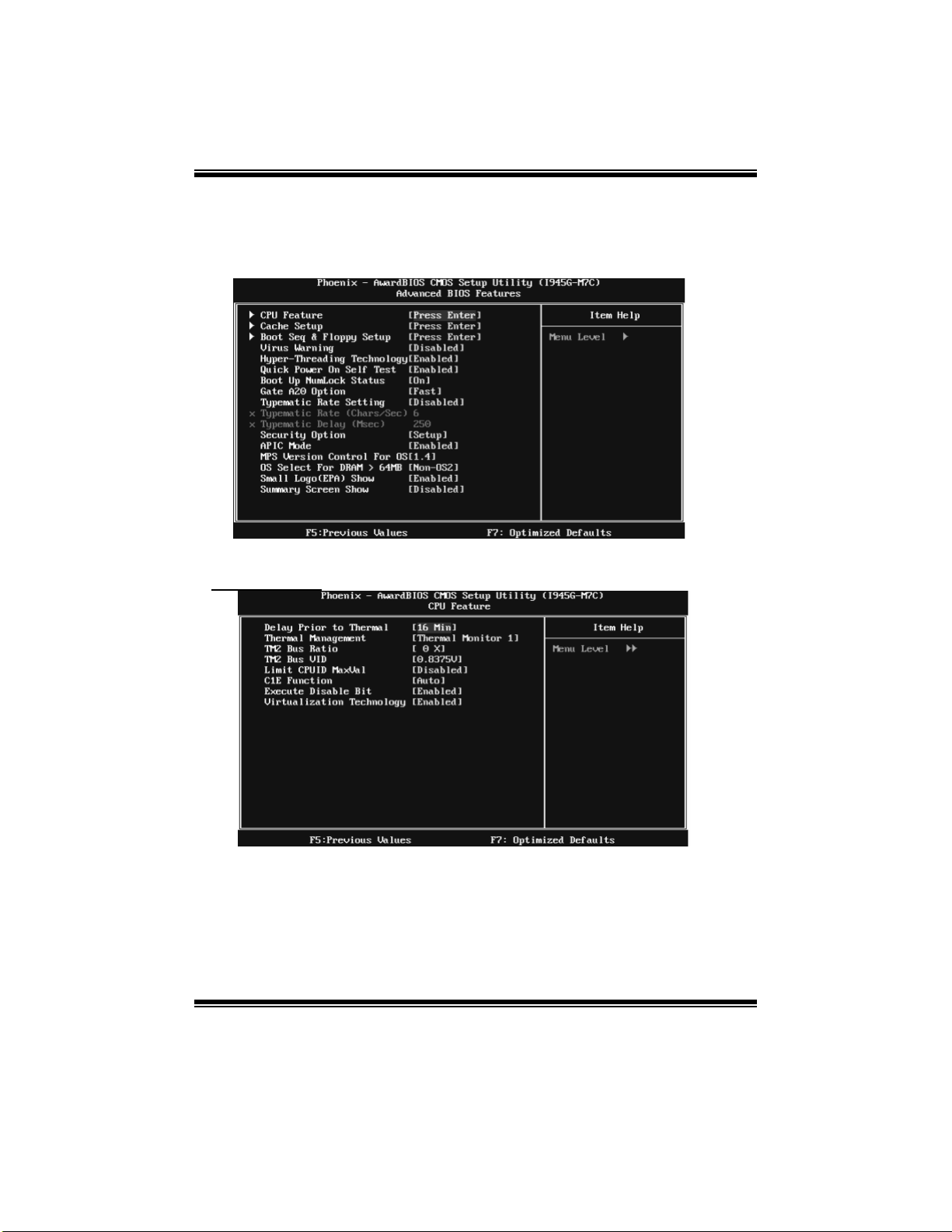
I945G-M7C BIOS SETUP
3 Advanced BIOS Features
Figure 3. Advanced BIOS Setup
CPU FEATURE
Delay Prior to Thermal
Set this item to enable the CPU Thermal function to engage after the specified time.
The Choices: 4 Min, 8 Min, 16 Min (default), 32 Min.
8
Page 61

I945G-M7C BIOS SETUP
Thermal Management
This option allows you to choose the thermal management method of your monitor.
The Choices: Thermal Moni tor 1 (default), Thermal Monitor2.
Notes: The choices will be different according to your CPU f eatures.
TM2 Bus Ratio
This option represents the frequency. (Bus ratio of the throttled performance state
that will be initiated when the on-die sensor goes from not hot to hot.)
Min= 0 Max= 255 Key in a DEC number.
The Choices: 0X (d efault).
TM2 Bus VID
This option represents the voltage of the throttled performance st ate that will be
initiated when the on-die sensor goes from not hot to hot.
The Choices: 0.8375V (d efau l t), 0 .8375 V-1 .6000 V.
Limit CPUID Max Val
Set limit CPUID MaxVal to 3, it should be “ Disabled” for Win XP.
The Choices: Disabled (d efault), Enabled.
C1E Function
This item allows you to choose the C1E function.
The Choices: Auto (default), Disabled.
Ex ecute Di sable Bit
When disabled, forces the XD featu re flag to always return 0.
The Choices: Enabled (default), Dis ab led.
Virtualiza tion Technology
When enabled, a VMM can utilize th e additional hardware capabilities provided by
Vanderpool Technology.
The Choices: Enabled (default), Disabled
9
Page 62

Cach e Setu p
I945G-M7C BIOS SETUP
CPU L3 Cache
Depending on the CP U/chipset in use, you may be able to increase
me mory access time with this option.
Enabl ed (default) Enable cache.
Disabled Disable cache.
Boot Seq & Floppy Setup
This item allows you to setup Boot Seq & Floppy.
10
Page 63

I945G-M7C BIOS SETUP
Hard Disk Boot Priority
These BIOS attempt to arrange the Hard Disk boot sequence automatically.
This will depend on which Hard Disk is installed.
The Choices: P ri. Master, Pri.Slave, Sec.Master, Sec.Slave, USBHDD0, USBHDD1,
USBHDD2 and Bootable Add-in Cards.
First/Second /T h i rd B oot Device
These BIOS attempt to load the operating system fro m th e devi ce in the sequence
selected in these items.
The Choices: Floppy, LS120, Hard Disk, CDROM, ZIP100, USB-FDD, USB-ZIP ,
USB-CDROM, LAN, Disabled.
Boot Oth er Devi ce
When enabled, BIOS will try to load the operating system from other device when it
failed to load from the three devices above.
The Ch oices: Enabled (defaul t ), Disabl ed
Swap Floppy Drive
For systems with two floppy drives, this option allows you to swap logical
drive assignments.
The Choices: Disabled (d efault), Enabled.
Boot Up Floppy Seek
Enabling this option will test the floppy drives to determine if they have 40 or 80
trac ks . Dis abl in g th is op tio n redu ces th e t i me i t t ak e s t o boot -up .
The Choices: Dis abl ed , Enabl ed (default).
11
Page 64

I945G-M7C BIOS SETUP
Report NO FDD for Win95
The Choices: NO (default), YES.
Virus Warning
This option allows you to choose the Virus Warning featu re that is used to protect
the IDE Hard Disk boot sector. If this function is enabled and an attempt is made to
write to the boot sector, BIOS will display a warning message on the screen and sound an
alarm beep.
Dis ab l ed (default) Virus protection is disabled.
Enabled Virus protection is activated.
Hyp er-Thread ing Techn ology
This option allows you to enable or disable CPU Hyper-Threading. “Enabled”
for Windows XP and Linux 2.4.x (OS optimized for Hyper-Threading Technology.)
“Disabled” for other OS (OS not optimized for Hyper-Threading Technology.)
The Choices: Enabled (default), Disabled.
Quick Power On Self Test
En ab li ng t his opti on wi ll cause an ab ridg ed v ersio n of t h e Po wer On
Self-Test (POST) to execute after you power up the computer.
Disabled Normal POST.
Enabl ed (default) E nable quick P OST.
Boot Up NumLock Status
Selects the NumLock Stat e after power on.
On (default) Numpad is arrow keys.
Off Numpad is number keys.
Gate A20 Option
Select if chipset or keyboard controller should control Gate A20.
Normal A pin in the keyboard controller controls GateA20.
Fast (default) Lets chipset control Gate A20.
Typemati c Rate Settin g
When a key is held down, the keystroke will repeat at a rate determined by
the keyboard controller. When enabled, the typematic rate and typematic
delay can be configured.
The Choices: Disabl ed (default), Enabled.
Typemati c Rate (Chars/S ec)
Sets the rate at which a keystroke is repeated when you hold the keydown.
The Choices: 6 (default), 8,10,12,15,20,24,30
12
Page 65

I945G-M7C BIOS SETUP
Typemati c Delay (Mse c)
Sets the delay time after the key is held down before it begins to repeat
the keystroke.
The Choices: 250 (default), 500, 750, and 1000.
Security Option
This option will enable only individuals with passwords to bring the system
online and/or to use the CMOS Setup Utility.
System A password is required for the system to boot and
is also required to access t he Setup Utility.
Setup (d efault) A password is required to access the Setup Utility only.
This item allows you to enable/disable the summary screen. Summary
s creen means s ystem configu ration and P CI device listing.
The Choices: Enabled, Di sab led (default ).
This will only apply if passwords are set from the Setup main menu.
APIC Mode
Selecting Enabled enables APIC device mode reporting from the BIOS to
the operating system.
The Choices: Enabled (default), Disabled.
MPS Versi on Con trol For OS
The BIOS supports version 1.1 and 1.4 of the Intel multiprocessor specification.
Select version supported by the operation system running on this computer.
The Choices: 1.4 (default), 1.1.
OS Select For DRAM > 64MB
A choice other than Non-OS2 is only used for OS2 systems with memory
exceeding 64MB.
The Choices: Non-OS2 (default ), OS2.
Small Logo (EPA) Show
This item allows you to select whether the “Small Logo” shows.
Enabl ed (default) “ Small Logo” shows when system boot up.
Disabled No “Small Logo” shows when system boots up.
Summary Screen S h ow
13
Page 66

I945G-M7C BIOS SETUP
4 Advanced Chipset Features
This submenu allows you to configure the specific features of the chipset installed on your
system. This chipset manag e bus speeds and access to system me mory res ources, such as
DRAM. It also coordinates communications with the PCI bus. The default settings that came
with your system have been optimized and therefore should not be changed unless you are
su sp ici ou s th at t he s ettin gs have b een ch a ng ed in c o r rectly .
Figure 4. Advanced Chipset Setup
DRAM Timing S electable
When synchronous DRAM is installed, the number of clock cycles of CAS
latency depends on the DRAM timing.
The Choices: B y SPD (default), Manual.
CAS Latency Time
When synchronous DRAM is installed, the number of clock cycles of CAS
latency depends on the DRAM timing.
The Choices: Auto (default), 3, 4, 5, 6.
DRAM RAS# to CAS# Delay
This field let you insert a timing delay between the CAS and RAS strobe
signals, used when DRAM is written to, read from, or refreshed. Fast gives
faster performance; and slow gives more stable performance. This field
applies only when synchronous DRAM is installed in the system.
The Choices: Auto (default), 2, 3, 4, 5, 6.
14
Page 67

I945G-M7C BIOS SETUP
DRAM RAS# Precharge
If an i nsufficient number of cycles is allowed for RAS t o accumulate its
charge before DRAM refresh, the refresh may be incomplete, and the
DRAM may fail to retain data. Fast gives faster performance; and Slow
gives more stable performance. This field applies only when synchronous
DRAM is installed in the system.
The Choices: Auto (default), 2, 3, 4, 5, 6.
Prech arg e Delay (T RAS )
This item controls the number of DRAM clocks to activate the precharge
delay.
The Choices: Auto (d efau l t), 4/ 5/6/ 7/8/ 9/10 /11/ 12/1 3/14 /15 .
Sys tem Memo ry Frequen cy
This item allows you to select the Memory Frequency.
The Choices: Auto (default), 400MHz, 533MHz, and 667MHz.
VGA Setting
PEG/Onchip VGA Control
This item allows you to enabled or disabled PEG/On-chip VGA controller.
The Choices: Auto (default), Onchip VGA, PEG Port.
PEG Force X1
When using on-chip VGA, this item has to be set as X1.
Dis ab l ed (default) P CI E xpress X16
Enabled PCI Express X1
On -Ch i p Frame B u ff er S i ze
This item will be different as your memory modules. When the memory size is decided,
this frame buffer size will also be fixed.
The Choices: 8MB (default ), 1MB.
DVMT Mode
The Choices : DVMT (de fault ), FIXED, BO TH .
DVMT/FIXED Memory Size
DVMT stands for „Dynamic Video Memory Technology“ . This is an enhancemnet of the
unified memory architecture (UMA) concept. Where the optimum amount of memory is
allocated for balanced graphics and system performance. DVMT dynamically reponds to
system requirements and applications demands, by allocating the proper amount of
display, texturing and buffer memory after the operating system has booted.
The Choices:128MB (Default), 64MB.
Boot Display
The Choices: Auto (d efaul t ), CRT, TV, EFP.
15
Page 68

I945G-M7C BIOS SETUP
SLP S4# Assertion Width
This item sets the minimum assertion width of the SLP-S4# signal to
guarantee the DRAM has been safely power-cycled.
The Choices: 4 to 5 Sec. (default), 3 to 4 Sec., 2 to 3 Sec., 1 to 2 Sec.
Sys tem BIO S Cach eab le
Selecting Enabled allows you caching of the system BIOS ROM at
F0000h~FFFFFh, resulting a b etter system performance. However, if any
program writes to this memory area, a system error may result.
The Choices: Enabled (default), Disabled.
Video BIOS Cacheab le
Select Enabled allows caching of the video BIOS, resulting a better
system performance. However, if any program writes to this memory area,
a system error may result.
The Choices: Disabled (default), Enabled.
Memory Hole At 15M-16M
You can reserve this area of system me mory for ISA ad apter ROM. When
this area is reserved it cannot be cached. The user information of
peripherals that need to use this area of system me mory u sually
discussed their memory requirements.
The Choices: Disabled (d efault), Enabled.
16
Page 69

I945G-M7C BIOS SETUP
PCI Ex press Root Port Func
PCI Express Port 1~6
This item allows you to select the PCI Express P ort.
The Choices: Auto (default), Enabled, Disabled.
Th is ite m al lo ws yo u to select the P CI-E Co mpli a n cy Mod e.
The Choices: v1.0a (d efau l t ), v1.0 .
PCI-E Compliancy Mode
17
Page 70

I945G-M7C BIOS SETUP
5 Integrated Peripherals
Figu re 5. Integrated Perip h erals
OnChip IDE Device
If you highlight the literal “Press Enter” next to the “OnChip IDE Device” label and
then press the enter key, it will take you a submenu with the following options:
18
Page 71

I945G-M7C BIOS SETUP
IDE HDD Block Mode
Block mode is also called block transfer, multiple commands, or multiple sector
read / write. If your IDE hard drive supports block mode (most new drives do),
select Enabled for automatic detection of the optimal number of block mode
(most new drives do), select Enabled for automatic detection of the optimal
number of block read / write per sector where the drive can support.
The Choices: Enabled (default), Di sabl ed .
IDE DMA Transfer Access
This item allo ws you to enable or disable the ID E transfer access.
The Choices: Enabled (defaul t), Disabled.
On-chip Primary/Secondary PCI IDE
This item allows you to enable or disable the primary/ secondary IDE Channel.
The Choices: Enabled (defaul t), Disabled.
IDE Primary/ S econ d ary Master/S lave PIO
The IDE PIO (Programmed Input / Output) fields let you set a PIO mode (0-4) for
each of the IDE devices that the onboard IDE interface supports. Modes 0 to 4 will
increase performance progressively. In Auto mode, the system automatically
determines the best mode for each device.
The Choices: Auto (default), Mode0, Mode1, Mode2, Mode3, and Mode4.
IDE Primary/ S econ d ary Master/S lave UDMA
Ultra DMA/100 functionality can be implemented if it is supported by the IDE hard
drives in your system. As well, your operating environment requires a DMA driver
(Windows 95 OSR2 or a third party IDE bus master driver). If your hard drive and
your system software both support Ultra DMA/100, select Auto to enable BIOS
su ppor t .
The Choices: Auto (default ), Disabled.
SATA Mode
The Choices: IDE (defaul t), RAID, AHCI.
On-Chip Serial ATA
This item allows you to choose:
Disabled: d isabl e d SA TA Cont rol l er
Combined Mode: PATA and SA TA are combined max of 2 ID E drivers
in each channel.
Enhanced Mode: enabled both SATA and PATA max o f 6 IDE drivers
are supported.
SATA Only: SATA is operating in legacy mode.
The Choices: Disabl ed, A uto, Co mbin ed Mode, Enhanced Mode (default),
and SATA only.
19
Page 72

I945G-M7C BIOS SETUP
SATA PORT Speed Settings
The Choices: Disabled (d efault), Force GEN I, Force GEN II.
PATA
IDE Mod e
The Choices: Primary (default), Secondary .
Onboard Device
If you highlight the literal “Press Enter” next to the “Onboard Device” l abel and
then press the enter key, it will take you a submenu with the following options:
USB Controller
Select Enabled if your system contains a Universal Serial Bus (USB) controller
and you have USB peripherals.
The Choices: Enabled (default), Disabled
USB 2.0 Con troller
This entry is to enable or disable EHCI controller only. This BIOS itself may/ may
not have high speed USB support. If the BIOS has high speed USB support built in,
the support will automatically turn on, when high speed device were attached.
The Choices: Enabled (defaul t ), Disabled.
USB Keyboard Support
This item allows you to enable or disable the USB Keyboard Legacy Support.
Enabled Enable USB Keyboard Support.
Dis ab l ed (default) Disable USB Keyboard Support.
20
Page 73

I945G-M7C BIOS SETUP
USB Mouse Support
This item allows you to enable or disable the USB Mouse Legacy Support.
Enabled Enable USB Mouse Support.
Dis ab l ed (default ) Disable USB Mo use Support.
Onboard AC97 Audio
This item allows you to decide to enable or disable to support AC97 Audio.
The Choices: Auto (d efault), Di s abl ed.
Onboard RAID <ITE8211>
The Choices: Enabled (defaul t ), Disabled.
Onboard RAID BIOS
The Choices: Enabled (default), Disabled.
Onboard 1394
The Choices: Enabled (defaul t ), Disabled.
Onboard LAN
This item allows you to enable or disable the Onboard LAN.
The Choices: Enabled (default), Disabled.
Onboard LAN Boot ROM
This item allows you to enable or disable the Onboard LAN Boot ROM.
The Choices: Disabled (default), Enabled.
Sup er IO Device
Press Enter to configure the Super I/O Device.
21
Page 74

I945G-M7C BIOS SETUP
Onboard FDC Controller
Select Enabled if your system has a floppy disk controller (FDC) installed on the system
board and you wish to use it. If install and FDC or the system has no floppy drive, select
Di sa bl ed in th is fi eld .
The Choices: Enabled (defaul t ), Disabled.
Onboard Serial Port 1
Select an address and corresponding interrupt for the first and second serial ports.
The Choices: Dis abl ed , 3F8/IRQ4 (default), 2F8/IRQ3, 3E8/IRQ4, 2E8/IRQ3, Auto.
Onboard Parallel Port
This item allows you to determine access onboard parallel port controller with which
I/O Address.
The Choices: 378/IRQ7 (default), 278/IRQ5, 3BC/IRQ7, Disabled.
Paral l el Port Mod e
The default value is SPP.
The Choices:
SPP (de fault ) Using P aral lel port as Standard P rinter Po rt.
EPP Using P arallel P ort as Enhanced Parallel Port.
ECP Using Parallel port as Extended Capabilities Port.
ECP+EPP Using Parallel port as ECP & EPP mode.
ECP Mode Use DMA
Select a DMA Channel for the port.
The Choices: 3 (default), 1.
PWRON After PWR-Fail
This setting specifies whether your system will reboot after a power
fail or interrupts occurs.
Off L eaves th e compu ter in the power o ff stat e.
On Reboots the computer.
Former-Sts Restores the system to the status before power failure or
interrupt occurs.
The Choices: Off (default ), On, Former-Sts.
22
Page 75

I945G-M7C BIOS SETUP
6 Power Management Setup
The Power Management Setup Menu allows you to configure your system to utilize energy
conservation and power up/power down features.
Figure 6. Power Managemen t Setu p
ACPI & Wake Up Events
23
Page 76

I945G-M7C BIOS SETUP
ACPI Function
This item displays the status of the Advanced Configuration and Power Management
(ACPI).
The Choices: Enabled (default ), Disabled.
ACPI Suspend Type
The item allows you to select the suspend type under the ACPI
operating system.
The Choices: S1 (POS) (default) Power on Suspend
S3 (STR) Suspend to RA M
S1 & S3 P O S+STR
Run VGABIOS if S3 Resume
Choosing Enabled will make BIOS run VGA BIOS to initialize the VGA card when
system wakes up from S3 state. The system time is shortened if you disable the
function, but system will need AGP driver to initialize the card. So, if the AGP
driver of the VGA card does not support the initialization feature, the display may
work abnormally or not function after S3.
The Choices: Auto (default), Yes, No.
Wake-Up b y PCI card
When you select “Enable”, a P ME signal from P CI card returns the syst em to
Ful l O n stat e.
The Choices: Enabl ed , Di sa bl ed (default).
Power On by Ring
An input signal on the serial Ring Indicator (RI) line (in other words, an
incoming call on the modem) awakens the system from a so ft off state.
The Choices: Enabl ed , Di sa bl ed (default).
USB KB/MS Wake-Up From S3
This item allows you to enable or disable USB keyboard wake up from S3.
The Choices: Disabled (d efault), Enabled.
Resume by Alarm
This function is for setting date and time for your computer to boot up.
During Disabled, you cannot use this function. During Enabled,
Choose the Date and Time.
Date (of Month) Alarm
You can choose which month the system will boot up.
Time (hh:mm:ss) Alarm
You can choose shat hour, minute and second the system will boot up.
Note: If you have changed the setti ng, you mus t let the system boo t up
until it goes to the operating system, before this function will work.
24
Page 77

I945G-M7C BIOS SETUP
POWER ON Function
This item allows you to choose the power on function.
The Choices: B utton Only (default), Password, Hot Key, Mouse Move/Click, Mouse
Double Click, Any Key, Keyboard 98.
KB POWER ON Password
Input password and press Enter to set the Keyboard power on password.
Hot Key Power ON
Input password and press Enter to set the Keyboard power on password.
The Choices: Ctrl-F1 (default), Ctrl-F2, Ctrl-F3, Ctrl-F4, Ctrl-F5,
Ctrl-F6, Ctrl-F7, Ctrl-F8, Ctrl-F9, Ctrl-F10, Ctrl-F11, and Ctrl-F12.
Reload T i mer E ven ts
Primary/Secondary IDE 0/1
You can select to enable or disable Primary or Secondary RAID 0 or
RAID 1 function under this item.
The Choices: Disabled (d efault), Enabled.
FDD, COM, LPT Port
You can select to enable or disable FDD, COM, and LPT port under this item.
The Choices: Disabled (d efault), Enabled.
PCI PIRQ [A-D]#
You can select to enable or disable P CI PIRQ [A-D]# under this item.
The Cho ices: Disabl ed (default), Enabled.
25
Page 78

I945G-M7C BIOS SETUP
Power Mana gement
This category allows you to select the type (or degree) of power saving and is directly
related to the following modes:
1. HDD Power Down.
2. Suspend Mode.
There are four options of Power Management, three of which have fixed mode settings
Min Saving (default)
Minimum power management.
Suspend Mode = 1 hr.
HDD Power Down = 15 min
Max. Power Saving
Maximum power management only available for sl CPU’ s.
Suspend Mode = 1 min.
HDD Power Down = 1 min.
User Define
Allows you to set each mode individually.
When not disabled, each of the ranges is from 1 min. to 1 hr. Except for HDD
Power Down which ranges from 1 min. to 15 min. and disable.
Video Off Method
Thi s opti on d eter min es th e man n er i n whi ch th e mon it or is go es bl a nk .
The Choices: DPMS (default), Blank Screen, V/H SYNC+Blank.
Video Off In Suspend
This determines the manner in which the monitor is blanked.
The Choices: Yes (defaul t), No.
Suspend Type
Select the Suspend Type.
The Choices: Stop Grant (default), PwrOn Suspend.
Mod em Use IRQ
This determines the IRQ, which can be applied in MODEM use.
The Choices: 3 (default), 4 / 5 / 7 / 9 / 10 / 11 / NA.
26
Page 79

Suspend Mode
The item allows you to select the suspend type under ACPI operating system.
The Choices: Disabled, 1 Min, 2 Min, 4 Min, 6 Min, 8 Min, 10 Min, 20 Min, 30 Min, 40
Min, 1 Hour (default ).
This selection will cause the system to turn off the vertical and horizontal
synchronization ports and write blanks to the video buffer.
Blank Screen
Thi s opti on o nly w rites bl anks to the vi d eo bu ffer .
HDD Power Down
When enabled, the hard disk drive will power down and after a set time of system
inactivity. All other devices remain active.
The Choices: Disabled, 1 Min, 2 Min, 3 Min, 4 Min, 5 Min, 6 Min, 7 Min, 8 Min, 9 Min,
10 Min, 11 Min, 12 Min, 13 Min, 14 Min, 15 Min (default).
Sof t-Off b y PWR-BTN
Pressing the power button for more than 4 seconds forces the system to enter the
Soft-Off state when the system has “hung.”
The Choices: Delay 4 Sec, Instant-Off (default).
HPET Support
This item allows you to enable or disable HPET.
The Choices: Enabled (default), Disabled.
HPET Mode
This item allows you to select the HPET mode.
The Choices: 32-bit mode (default), 64-bit mode.
I945G-M7C BIOS SETUP
27
Page 80

I945G-M7C BIOS SETUP
7 PnP/PCI Configurations
This section describes configuring the PCI bus system. PCI, or Personal Computer
Interconnect, is a system which allows I/O devices to op erate at speeds nearing the speed of
the CP U itself uses when communicating with its own special components. This section
covers some very technical i tems and it is strongly recommended that only experienced
users should make any changes to the default settings.
Figure 7. PnP/PCI Configurations
Init Display First
This item allows you to decide to active whether PCI Slot or on-chip VGA first.
The Choices: PCI Slot (default), PCIEx, Onboard.
Resou rces Con trolled B y
By Choosing “ Auto (ESCD)” (defaul t), the system BIOS will detect the
system resources and automatically assign the relative IRQ and DMA
channel for each periph eral. By Choosing “ Manual ”, the user will need to
assign IRQ & DMA for add-on cards. Be sure that there are no IRQ/DMA
and I/O port conflicts.
The Choices: Auto (ESCD) (defaul t), Manual.
28
Page 81

I945G-M7C BIOS SETUP
IRQ Resou rces
This submenu will allow you to assign each system interrupt a type,
depending on the type of device using the interrupt. When you press the
“Press Enter” tag, you will be directed to a submenu that will allow you to
configure the system interrupts. This is only configurable when
“Resources Controlled By” is set to “ Manual”.
IRQ-3 assigned to PCI Device
IRQ-4 assigned to PCI Device
IRQ-5 assigned to PCI Device
IRQ-7 assigned to PCI Device
IRQ-9 assigned to PCI Device
IRQ - 10 as sign ed to P CI D ev i ce
IRQ - 11 as sign ed to P CI D ev i ce
IRQ - 12 as sign ed to P CI D ev i ce
IRQ - 14 as sign ed to P CI D ev i ce
IRQ - 15 as sign ed to P CI D ev i ce
PCI / VGA Palette Snoop
Choose Disabled or Enabled. Some graphic controllers that are not VGA
compatible take the output from a VGA controller and map it to their
display as a way to provide boot information and VGA compatibility.
However, the color information coming from the VGA controller is drawn
from the palette table inside the VGA controller to generate the proper
colors, and the graphic controller needs to know what is in the palette of
the VGA controller. To do this, the non-VGA graphic controller watch for
the Write access to the VGA palette and registers the snoop data. In P CI
based systems, where the VGA controller is on the P CI bus and a
non-VGA graphic controller is on an ISA bus, the Write Access to the
palette will not show up on the ISA bus if the PCI VGA controller responds
to the Write.
In thi s case, t h e P CI VG A c on troll e r sh ou ld n ot resp on d to th e W rit e , i t
should only snoop the data and permit the access to be forwarded to the
ISA bus. The non-VGA ISA graphic controller can then snoop the data on
the ISA bus. Unless you have the above situation, you should disable
th is opti on.
Dis ab l ed (default ) Di sable the function.
En ab l ed En ab l e the fun cti on .
Maximum Payload Size
Set the maximu m payload size for Transaction packets (TLP).
The Choice: 4096 (default.), 128, 256, 512, 1024, 2048.
29
Page 82

I945G-M7C BIOS SETUP
8 PC Health Status
Figure 8. PC Health Status
CPU FAN Control
The Choice “smart” can make your CPU FAN to reduce noise.
The Choices: Smart (default), Always On.
CPU Fan Off<℃>
If the CPU Temperature is lower than the set value, FAN will turn off.
The Choices: Min=0,.Max=127, Key in a DEC number.
CPU Fan Start<℃>
CPU fan starts to work under smart fan function when arrive this set value.
The Choices: Min=0,.Max=127, Key in a DEC number.
CPU Fan Fu ll speed <℃ >
When CPU temperature is reach the set value, the CPU fan will work under Full Speed.
The Choices: Min=0,.Max=127, Key in a DEC number.
Start PWM Value
When CPU temperature arrives to the set value, the CPU fan will work under Smart Fan
Function mode. The range is from 0~127, with an interval of 1.
The Choices: Min=0,.Max=127, Key in a DEC number.
30
Page 83

I945G-M7C BIOS SETUP
Slope PWM
Increasing the value of slope PWM will raise the speed of CP U fan.
The Choices: 1 PWM Value/℃(d efault), 2 P WM Value/℃, 4 P WM Value/℃, 8 P WM
Val ue/ ℃,16 P W M Val u e/ ℃.
SHUTDOWN TEMPERATURE
This item allows you to set up the CPU shutdown Temperature. This item only effective
under Windows 98 ACPI mode
The Choices: 65
SHOW H/W MONITOR IN POST
If you computer contain a monitoring system, it will show PC health status during POST
stage. The item offers several delay time to select you want.
The Choices: Enabled (default), Disabled.
CPU VCORE, NB/SB VOLTAGE, +3.3V, +5. 0V, +12.0V, DDR VOLTAGE,
5V(SB),VOLTAGE BATTERY
Detect the system’s voltage status automatically.
CURRENT CPU TEMP
This field displays the current temperature of CPU.
CURRENT CPU FAN SPEED
This field displays the current speed of CPU fan.
CURRENT SYS FAN SPEED
This field displays the current speed SYSTEM fan.
O
C/140OF, 70OC/ 1 4 9OF, 75OC/ 1 5 8OF, Disa bl ed (default).
31
Page 84

I945G-M7C BIOS SETUP
9 Performance Booster Zone
Figure 9. Frequency/ Voltage Control
CPU Voltage
This item allows you to select CP U Voltage Control.
The Choices: StartUp (default), +0.012V~+0.787V.
CPU Clock Ratio
This item allows you to select the CPU Ratio.
Min = 8 Max = 50 Key in a DEC number.
The Choices: 8X (d efault).
CPU Voltage Regulator
This item allows you to select CP U Voltage Regulator
The Choices: Default (default), +5%, +15%.
DDR Voltage Regulator
This item allows you to select DDR Voltage Regulator
The Choices: 1.8V (default), 1.9V, 2.0V, 2.1V.
Auto Detect PCI Clk
This item allows you to enable or disable auto Detect PCI Clock.
The Choices: Enabled (default), Disabled.
32
Page 85

I945G-M7C BIOS SETUP
CPU Clock
This item allows you to select CPU Clock, and CPU over clocking.
Min= 100 Max = 300 Key in a DEC number.
The Choices: 100Mhz (default).
PCIE Clock select
The Choices: Auto(default), Fixed 100, Manual
PCIE Clock
This item will activated only when “PCIE Clock Select” is set to “Manual”
The Choices: Min= 100, Max= 200, Key in a DEC number.
Specia l N otice:
If unfortunately, the system’s frequency that you are selected is not
functioning, there are two methods of booting-up the system.
Method 1:
Clear the COMS data by setting the JCOMS1 ((2-3) closed)) as “ON”
status. All the CMOS data will be loaded as defaults setting.
Method 2:
Press the <Insert> key and Power button simultaneously, after that
keep-on pressing the <Insert> key until the power-on screen showed.
This action will boot-up the system according to FSB of the processor
It’s s trongly recommend ed to set CPU Vcore and clock in def ault setting. If the CPU
Vcore and clock are not in default setting, it may cause CPU or M/B damage.
33
 Loading...