

Page 1

I915P-A 7 PCI-ED
I91PL-A7 PCI-ED
FCC Inf or m at ion and Copyright
This equipment has been t ested and f ound to comp ly w ith the l imits of a Class
B digi ta l dev i ce, pur su ant to Part 15 of t he FCC R ul es. Th ese lim it s ar e de sign ed
to provide reasonable protection against harmful interference in a residential
installat ion. This equ ipment ge nerate s uses a n d can radiate radio frequen cy
en ergy and, if not install ed and used in accordance w ith the instruct ions, may
caus e harmful interference to rad io communi cat i ons. Th ere i s no guarantee
that interference will not occur in a particular installation.
The vendor makes no representations or warranties with respec t to the
con te nt s h ere an d sp ec iall y di scl a im s an y im pl ied w arrant ie s of m er cha nt ab il it y
or fi tness for any purpose. Further the vendor rese rves the right to revise this
publica tion an d to m ake chan ges to the contents here with ou t obligation to
notif y any party beforeh a nd.
Duplication of this publication, in part or in whole, is not allowed without first
obt aining the vendor’s approval in writing.
The con te nt of thi s u ser’s m anu al i s subje ct to b e ch ang ed with ou t no ti ce an d
we will not be responsible for any mistakes found in this user’s manua l. All the
brand a nd prod uct n ames are trademarks of their r especti ve companies.
i
Page 2

Table of C ont ent s
Chapter 1: Introduction ................................................................3
1.1 Motherboard Features.................................................. 3
1.2 Package Checklist.........................................................7
1.3 Layout and Components............................................... 8
Chapter 2: Hardware Information ..............................................9
2.1 Installing Central Processing Unit (CPU)........................ 9
2.2 FAN Headers..............................................................10
2.3 Installing System Memory ...........................................11
2.4 Connectors and Slots ...................................................11
Chapter 3: Headers & Jumpers Setup...................................12
3.1 How to Setup Jumpers.................................................12
3.2 Detail Settings.............................................................12
Chapter 4: Useful Help............................................................... 17
4.1 Award BIOS Beep Code...............................................17
4.2 Extra Information ........................................................17
4.3 Troubleshooting ..........................................................19
Chapter 5: WarpSpeeder™....................................................... 20
5.1 Introduction................................................................20
5.2 System Requirement....................................................20
5.3 Installation..................................................................21
5.4 [WarpSpeeder™] includes 1 tray icon and 5 panels........23
ii
Page 3

I915P-A 7 PCI-ED
I91PL-A7 PCI-ED
CHAPTER 1: INTRODUCTION
1.1 MOTHERBOARD FEATURES
A. Hardware
CPU
Supports LGA 775.
Supports single Intel Pentium 4 processor.
Supports Intel Celeron D processor.
Front Side Bus at the following frequency ranges:
- 533 MT/s (133 MHz Core Cl ock)
- 800 MT/s (200 MHz Core Cl ock)
Supports Hyper-Threading Technology.
Chi pset
Northbridge: Intel 915PL/915P.
Southbridge: Intel ICH6.
Dimensions
ATX Form Factor: 29.35cm (L ) x 24.4cm (W)
Op eratin g System
Supports Windows 98SE, Windows 2000, Windows Me, and
Windows XP.
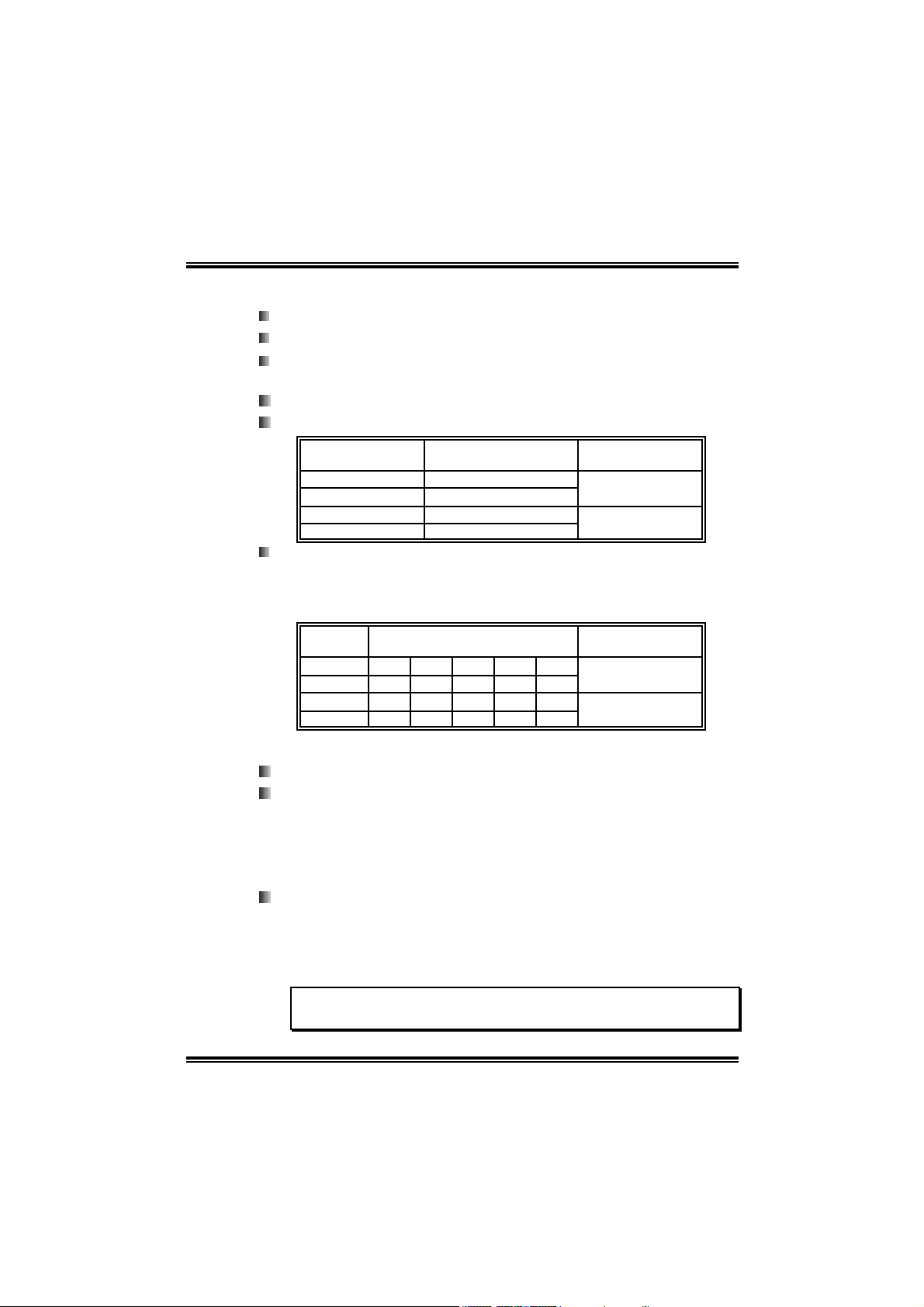
I915P-A7 PCI-ED S ystem Memory
Su pports Dual Channel DDR wi th 8 banks in total.
Supports DDR333 and DDR4 00.
Su pports 256Mb, 512Mb, and 1G-Mb DDR te chnologies for x8
an d x16 non-ECC DDR d evices.
Registered DIMMs are not supported.
Maximum DRAM address decode space of 4GB.
DI MM Socket
Location
DDRA1 256MB/512MB/1GB *1
DDRA2 256MB/512MB/1GB *1
DDRB1 256MB/512MB/1GB *1
DDRB2 256MB/512MB/1GB *1
DDR Module To t al Memory Siz e
Max is 4GB.
3
Page 4
I915P-A 7 PCI-ED
I91PL-A7 PCI-ED
I9 1PL- A7 PCI-ED S ystem Mem ory
Su pports Dual Channel DDR wi th 4 banks onl y.
Supports DDR333 and DDR4 00.
Su pports 256Mb, 512Mb, and 1G-Mb DDR te chnologies for x8
an d x16 non-ECC DDR d evices.
Registered DIMMs are not supported.
Maximum DRAM address decode space of 2GB.
DI MM Socket
Location
DDRA1 256MB/512MB/1GB *1
DDRA2 256MB/512MB/1GB *1
DDRB1 256MB/512MB/1GB *1
DDRB2 256MB/512MB/1GB *1
DDR Install ing Precautions
This system supports both Single Side (SS) and Double Side
(DS) Memory type. Please be aware of memory module
installation rules, or it may cause the system fail to boot-up.
DIMM
Socket
DDRA1 SS x SS DS x
DDRA2 x SS SS x DS
DDRB1 SS x SS DS x
DDRB2 x SS SS x DS
Mem ory Module Comb ina t ion
DDR Module To t al Memory Siz e
Max is 1GB.
Max is 1GB.
To t al Memory
Size
Max is 1GB.
Max is 1GB.
Slots
Three 32bit PCI bus master slots.
One PCI-Express (PCI-E) x 16 slot:
- PCI-Express 1.0a compliant.
- Maximum theoretical realized bandwidth of 4GB/s
simultaneously per direction, for an aggregate of 8GB/s
totally.
One PCI-Extreme (PCI-EX) slot:
- PCI-Express 1.0a compliant.
- Supports data transfer speed up to 1GB/s per direction.
(See p.13 for detail information.)
Special PCI-Express Dual Feature
This special function supports Dual View (two graphic cards).
4
Page 5

I915P-A 7 PCI-ED
I91PL-A7 PCI-ED
LAN
Chip: RTL8100C
Supports 10 Mb/s, and 100 Mb/s auto-negotiation.
Ha l f/Full d upl e x capabili ty.
Supp o rts A CPI po wer ma nageme nt.
On-board A C’97 Sound Cod ec
Chi p: ALC655
Support 6 channels.
Supports S/PDIF-Out and S/PDIF-In (optional) functions.
Compliant with AC’97 Version 2.3 specification.
Super I/O
Chip: ITE IT8712F.
Low Pin Count Interface.
Provides the most commonly used legacy Super I/O
functionality.
Environment Control initiatives:
- H/W Monitor.
- Fan Speed Controller.
- ITE's "Smart Guardian" function.
IEEE 1394 Ch ip (op t i o na l)
Ch i p: VIA VT 6307 .
Supp o rts two 1394 A Fi re wi re p o rts up t o 40 0Mb / s in di vidu all y.
Se rial ATA
Controller integrated in ICH6.
Supports 4 Serial ATA (SATA) ports.
- Integrated AHCI controller.
- Compliant with Serial ATA 1.0 specification.
- Data transfer rates up to 1.5Gb/s.
On-board IDE
One connector supports 2 IDE disk drives.
Supports PIO Mode 0~4, Bride Mode and Ultra DMA 33/66/100
B u s M a st e r Mo de .
5
Page 6
I915P-A 7 PCI-ED
I91PL-A7 PCI-ED
I nt er n al On-board I /O Co nn ec tors a nd He ader s
1 IDE connector supports 2 hard disk devices.
1 front panel header supports front panel facilities.
1 CD-in connector supports 1 CD-ROM audio-in device.
1 SPDIF-out connector supports digital audio-out function.
1 front audio header supports front panel audio-out function.
1 chassi s open header supports PC case-opened warning
function.
1 Floppy port supports 2 FDD with 360K, 720K, 1.2M, 1.44M
and 2.88Mbytes.
1 SPDIF-in connector supports digital audio-in function
(optional).
1 1394A header supports 1 front panel 1394A Firewire port
(optional).
2 USB headers support 4 USB 2.0 ports at front panel.
4 serial ATA connectors support 4 SATA devices.
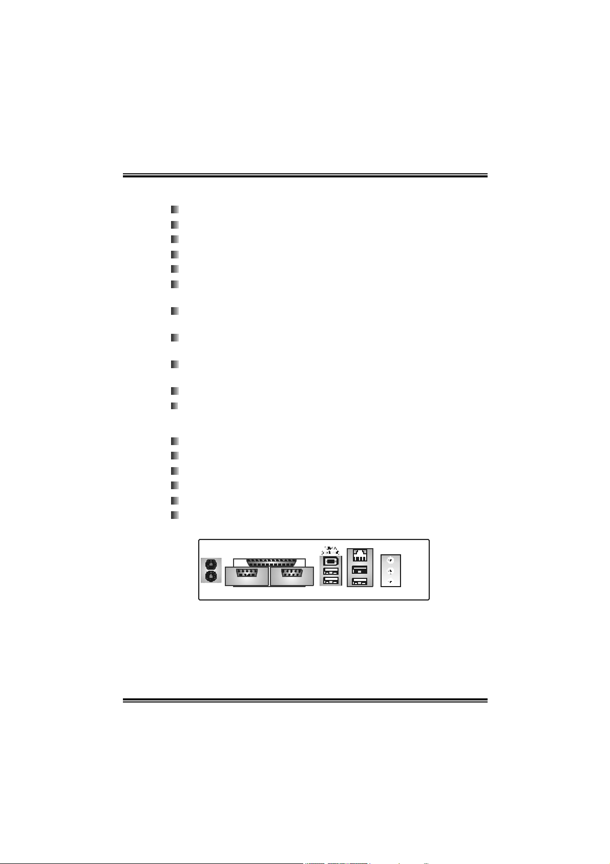
Back Panel I/ O Connector s
4 USB 2.0 ports.
1 Serial port. (COM2 is optional).
1 Pa ralle l (P ri nter) port.
1 RJ-45 LAN jack.
1 PS/2 Mouse & Keyboard port.
1 vertical audio port including 1 line-in connector, 1 line out
connector, and 1 MIC in connector.
USB x2
L AN Jack
USB x2CO M1
Line In/
Surr oun d
Line Out
Mic In 1/
Ba se/Ce nter
PS/2
Mo u se
PS / 2
Key b oar d
Pri nt er Po rt
COM2
( opt io na l)
6
Page 7

I915P-A 7 PCI-ED
I91PL-A7 PCI-ED
B. BIOS & Software
BIOS
Award legal BIOS.
Supports APM1.2.
Supports ACPI.
Supports USB Function.
Bundled Software
Supports Warpspeeder™, 9th Touch™, WINFLASHER™ and
FLASHER™.
1.2 PACKAGE CHECKLIST
FDD Cable X 1
HDD Cab l e X 1
S/PDIF Cable X 1
User ’ s Ma nu al X 1
Serial ATA Cable X 1
Fully Setup Dri ver CD X 1
Rear I/O Panel for ATX Case X 1
USB 2.0 Cable X1 (optional)
IEEE 1394 Cable X 1 (optional)
Serial ATA Power Switch Cable X 1 (optional)
7
Page 8
I915P-A 7 PCI-ED
I91PL-A7 PCI-ED
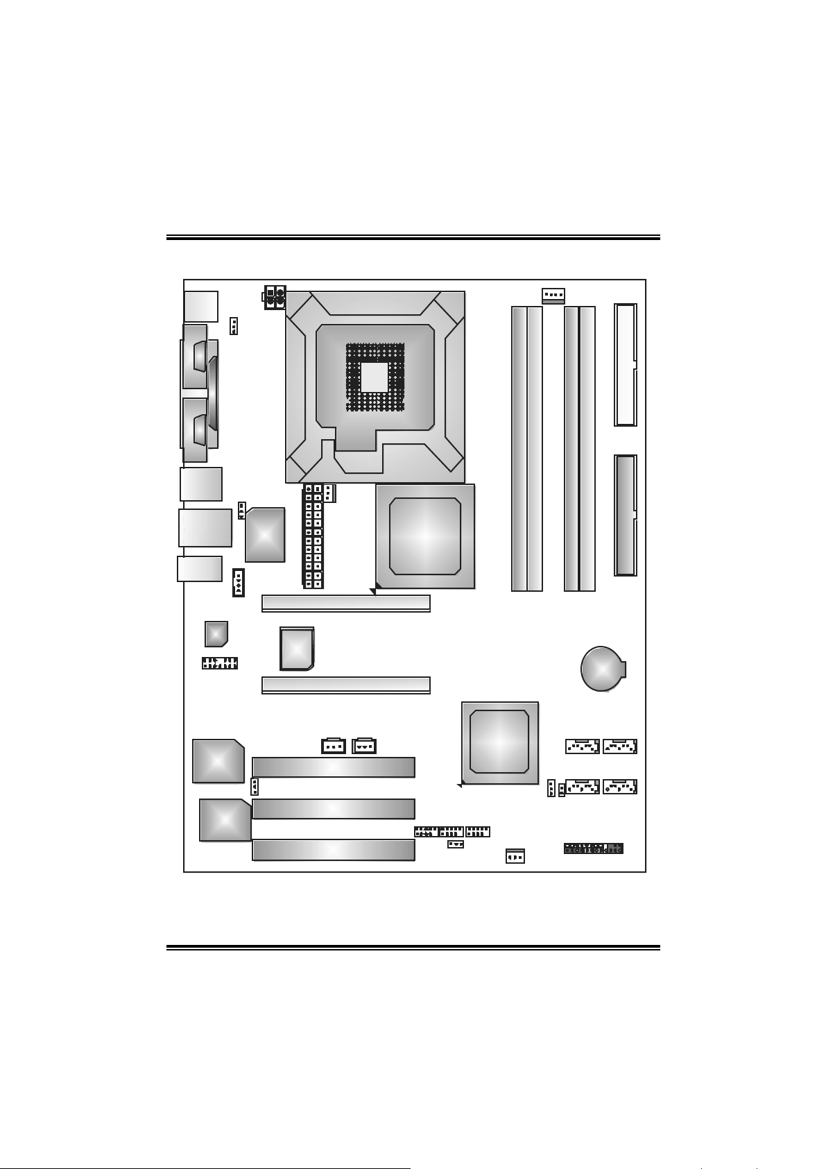
1.3 LAYOUT A ND COMPONE NTS
JAT XPW R2
JKBMS1
JKBV1
JCOM1
JCO M2
( op t iona l)
C
C
O
O
M
M
1
1
Parallel Port (JPRNT1)
C
O
M
2
LGA775
CPU1
JCFA N1
FDD1
DDRA1
DDRA2
DDRB1
DDRB2
J1394_USB1
JRJ45USB1
JAU DI O 1
Codec
JAUDI OF1
JUSBV1
JCDIN1
Super
I/ O
JAT XPWR1
BIOS
(optional)
LAN
J1394PWR1
(op ti o nal )
I EEE13 94
Chi p
(opt ional)
Note: ■ represents the 1st pi n .
JSF AN 2
( opt iona l )
PCI EXP RESS x1 6
PC I-EXT REME
PC I1
PCI2
PCI3
Intel 915P
Intel 915 PL
JS PDIF_ OUT1JSPDIF_IN1
JUSB3
IDE1
or
BAT1
SATA3
Intel
SATA4
ICH6
SATA1
SATA2
JC L1JC MOS1
J1394A1
(o pti o nal )
JUSB4
JUSBV3_ 1
JS FAN1
JPANEL 1
8
Page 9
I915P-A 7 PCI-ED
I91PL-A7 PCI-ED
CHAPTER 2: HARDWARE INFORMATION
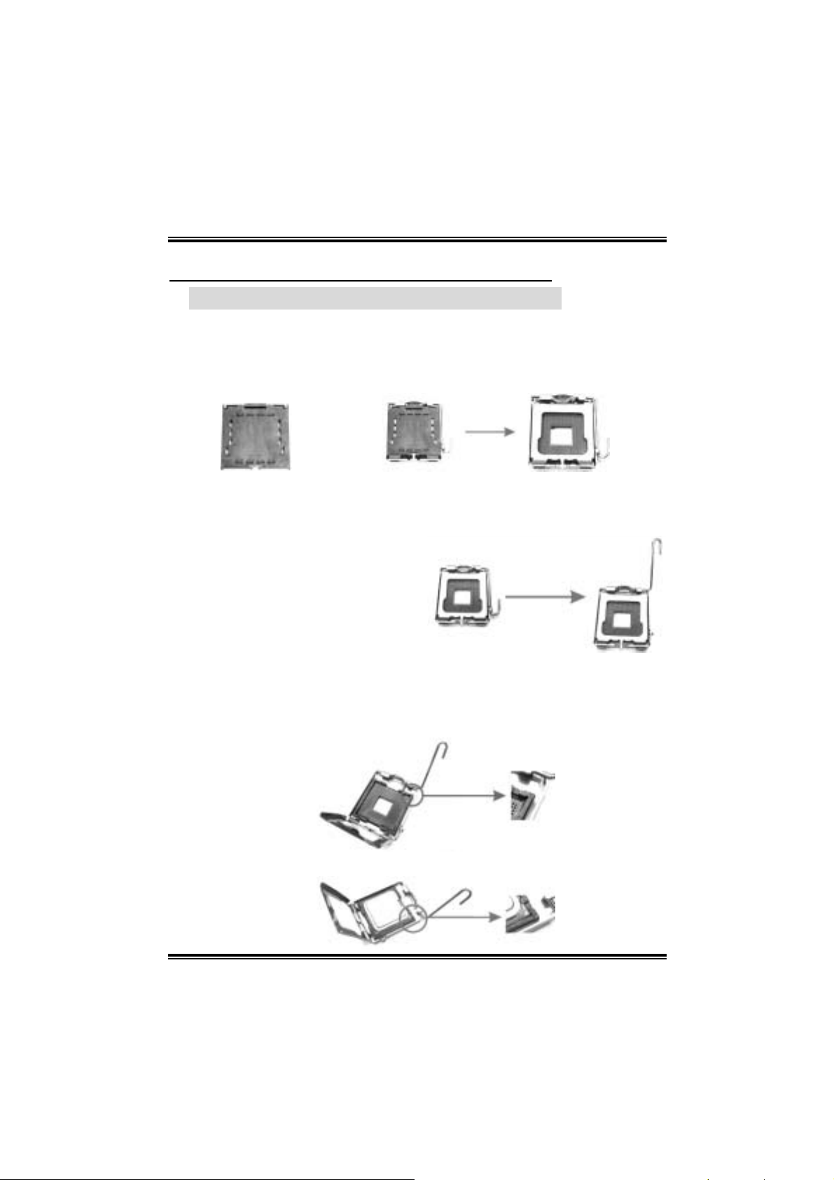
2.1 INST ALL ING CENTRAL PROCESSING UNIT (CPU)
Special Notice:
Remo v e Pin Cap before installatio n, and ma ke goo d preservation for
future use. When the CPU is remo v ed, cover the Pin Cap on the empty
socket to ensure pin legs won’ t be damaged.
pin cap
Step 1: Pull the lever sideways away from the socket and then raise the
lever up to a 90-degree angle.
Step 2: Look for the black cut edge on socket, and the white dot on CPU
should point wards this black cut edge. The CPU will fit onl y in the
correct orientation.
Step 2-1:
Step 2-2:
9
Page 10
I915P-A 7 PCI-ED
I91PL-A7 PCI-ED
Step 3: Hold the CPU down firmly, and then close the lever to complete
the installation.
Step 4: Put the CPU Fan on the CPU and buckle it. Connect the CPU FAN
power cable to the JCFAN1. This completes the installation.
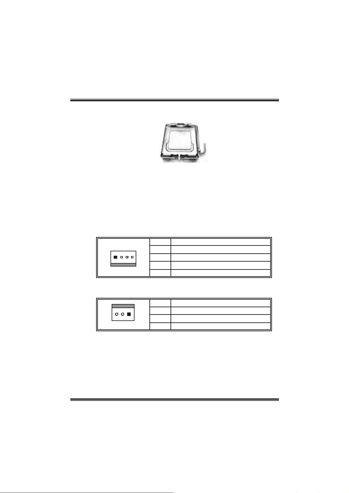
2.2 FAN HEADERS
These fan headers support cooling-fans built in the computer. The fan
wiring and plug may be different according to the fan manufacturer.
Connect the fan cable to the connector while matching the black wire to
pin#1.
JCFAN1: Pow er Source for CPU Fa n
Pin Assignment
14
1 Ground
2 Power
3 FAN RPM rate sense
4 Smart Fan Control
JSFAN1/ J SF AN2: P ower Sourc e for Sy st em Fa n
(JSFAN2 is optional.)
Pin Assignment
1 Ground
13
Note:
The JCFAN1, JSFAN1 and JSFAN2 support system cooling fan with
Smart Fan Control utility. They support 4-pin and 3-pin head connectors.
When connecting with wires onto connectors, please note that the red
wire is the positive and should be connected to pin#2, and the black wire
is Ground and should be connected to GND.
2 Smart Fan Control
3 FAN RPM rate sense
10
Page 11

I915P-A 7 PCI-ED
I91PL-A7 PCI-ED
2.3 INST ALL ING SYST EM MEMORY
1. Unlock a DIMM slot by pressing the
retaining clips outward. Align a DIMM
on the slot such that the notch on the
DIMM matches the break on the Slot.
2. Insert th e DIMM verti call y and fi rml y
into the slot until the retaining chip
snap back in place and the DIMM is
properly seated.
2.4 CONNECTO RS AND SLOTS
FDD1: Floppy Disk Connecto r
The motherboard provides a standard floppy disk connector that
supports 360K, 720K, 1.2M, 1.44M and 2.88M floppy disk types. This
connector supports the provided floppy drive ribbon cables.
IDE1: Hard Disk Connector
The motherboard has a 32-bit Enhanced PCI IDE Controller that
provides PIO Mode 0~5, Bus Master, and Ultra DMA 33/ 66/ 100
functionality. The IDE connectors can connect a master and a slave
drive, so you can connect up to four hard disk drives.
PCI1~PCI3: Peripheral Component Interconnec t Slots
This motherboard is equipped with 3 standard PCI slots. PCI stands
for Peripheral Component Interconnect, and it is a bus standard for
expansion cards. This PCI slot is designated as 32bits.
PCI-Ex 4: PCI-Extreme Slot
This PCI-Ex 4: PCI-Extreme slot is a special design for PCI-Express
interface graphic cards.
The PCI-Ex 4: PCI-Extreme slot is compliant with PCI-Express 1.0a
specification.
T his PCI-Ex 4: PCI-Extreme slot is compatible with PCI-E x4 and
PCI-E x1 expansion card.
The bandwidth of data transfer is up to 1GB/s per direction, and for
an aggregate of 2GB/s in total.
11
Page 12
I915P-A 7 PCI-ED
I91PL-A7 PCI-ED
CHAPTER 3: HEADERS & JUMPERS SETUP
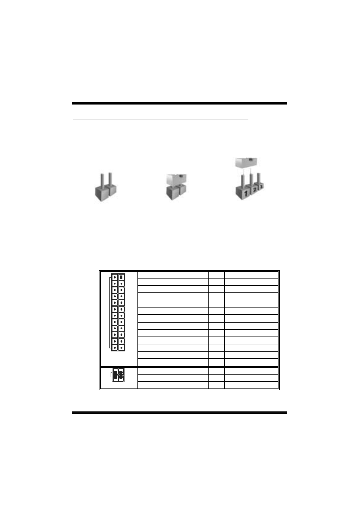
3.1 HOW TO SETUP JUMPERS
The illustration shows how to set up jumpers. When the jumper cap is
placed on pins, the jumper is “close”, if not, that means the jumper is
“open”.
Pin opened Pin closed Pin1-2 closed
3.2 DETAIL SETTINGS
JATXPWR1/J ATXPWR2: ATX Power Con nect ors
JATXPWR1: This connector allows user to connect 24-pin power
connector on the ATX power supply.
JATXPWR2: By connecting this connector, it will provide +12V to CPU
power circuit.
1
13
24
JATXPWR1
1
2
JATXPWR2
Pin Assignment Pin Assignment
1 +3.3V 13 +3.3V
2 +3.3V 14 -12V
3 Ground 15 Ground
4 +5V 16 PS_ON
5 Ground 17 Ground
6 +5V 18 Ground
7 Ground 19 Ground
8 PW_ON 20 -5V
9 Standby Voltage +5V 21 +5V
10 +12V 22 +5V
12
11 +12V 23 +5V
12 2 x 12 Detect 24 Ground
3
Pin Assignment Pin Assignment
4
1 +12V 3 Ground
2 +12V 4 Ground
12
Page 13
I915P-A 7 PCI-ED
t
I91PL-A7 PCI-ED
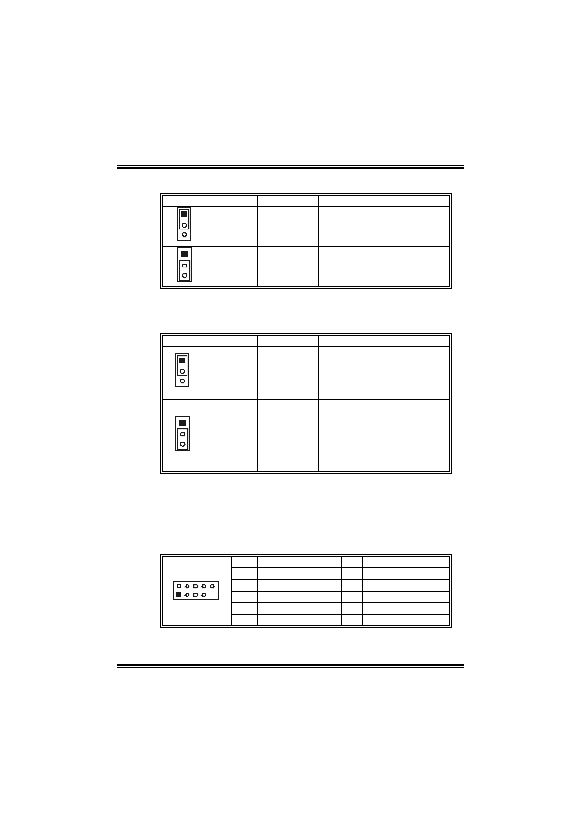
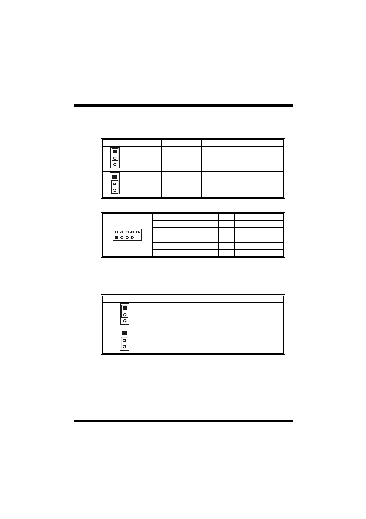
JKBV1: Power S ource Header for PS/2 Keyboard and Mouse
Assignment Description
1
+5V
3
Pin 1-2 close
1
3
Pin 2-3 close
Note: I n order to support this f unction “Power-on system v ia keyboard and
mouse”, “JKBV1” jumper cap should be placed on Pin 2-3.
+5V Standby
Voltage
+5V f or PS/2 key board and
mouse.
PS/2 mouse and keyboard are
powered with +5V standby
v oltage.
JUS B V1/JUSBV3 _1 : Powe r S ource H eade r f or US B Por ts
Assignment Description
1
+5V
3
Pin 1-2 close
1
3
Pin 2-3 close
Note: I n order to support this f unction “Power-on system v ia USB dev ice,”
“JUSBV1/ JUSBV3_1” jumper cap should be placed on Pin 2-3 individually.
+5V standby
Voltage
JUSBV1: +5V for USB ports at
JUSB_19341 and
JRJ45USB1.
JUSBV3_1: +5V for USB ports a
front panel (JUSB3/JUSB4).
JUSBV1: USB ports at
JUSB_19341 and
JRJ45USB1 are powered by
+5V standby voltage.
JUSBV3_1: USB ports at front
panel (JUSB3/JUSB4) are
powered by +5V.
JUSB3/JUSB4: Heade rs for USB2.0 Ports at Front Panel
This header allows user to connect additional USB cable on the PC front
panel, and also can be connected with internal USB devices, like USB
card reader.
Pin Assignment Pin Assignment
2
1
10
1 +5V (f us ed) 2 +5V (f used)
3 USB- 4 USB5 USB+ 6 USB+
7 Ground 8 Ground
9 Key 10 NC
13
Page 14
I915P-A 7 PCI-ED
I91PL-A7 PCI-ED
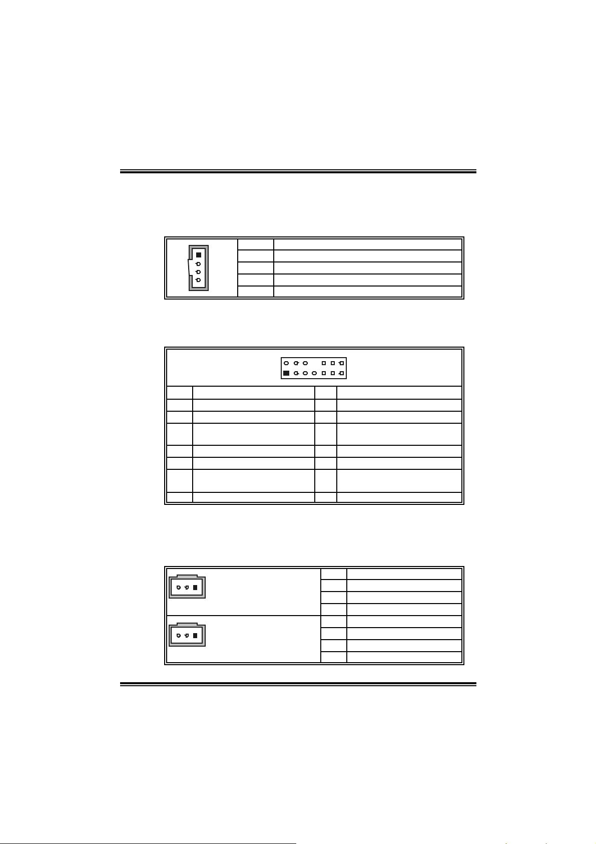
JCDIN1: CD-R OM Aud io-i n Connector
This connector allows user to connect the audio source from the variety
devices, like CD-ROM, DVD-ROM, PCI sound card, PCI TV turner card
etc..
1
4
Pin Assignment
1 Left channel input
2 Ground
3 Ground
4 Right channel input
JAUDIOF1 : Fron t Panel Audio-out Hea der
This header allows user to connect the front audio out put cable with the
PC front panel. It will di sable the output on back panel audi o connectors.
2
14
1
Pin Assignment Pin Assignment
1 Mic in/center 2 Ground
3 Mic power/Bass 4 Audio power
Right line out/Speaker out
5
Right
7 Reserv ed 8 Key
9 Left line out/Speaker out Left 10 Left line out/Speaker out Left
Right line in/Rear speaker
11
Right
13 Left line in/Rear speaker Left 14 Lef t line in/Rear speaker Left
13
Right line out/Speaker out
6
Right
Right line in/Rear speaker
12
Right
JSPDIF_OUT1/JSPDIF_IN1: Digital Au dio Connectors
(J SPD I F _I N 1 i s op tio n al .)
This connector allows user to connect the PCI bracket SPDIF output and
input headers.
Pin Assignment
1 +5V
13
JSPDIF_OUT
13
JSPDIF_IN1 (optional)
2 SPDIF_OUT
3 Ground
Pin Assignment
1 +5V
2 SPDIF_IN (optional)
3 Ground
14
Page 15
I915P-A 7 PCI-ED
I91PL-A7 PCI-ED
J1394PW R1: Power Source for 1394 Firewire Port (optional )
This header allows user to connect the digital image device, like DV, D8,
or V8, etc.
Assignment Description
1
+3.3V SB +3.3V SB for 1394 chipset.
3
Pin 1-2 close
1
3
Pin 2-3 close
+3.3V
+3.3V f or 1394 chipset.
(Default)
J1394A1: Heade r for 1394A Firewire Port at Fron t Panel (optional)
Pin Assignment Pin Assignment
2
1
10
1 A+ 2 A3 Ground 4 Ground
5 B+ 6 B7 +12V 8 +12V
9 Key 10 Ground
JCMOS 1 : C lear CMOS He ader
By placing the jumper on pin2-3, it allows user to restore the BIOS safe
setting and the CMOS data, please carefully follow the procedures to
avoid damaging the motherboard.
Assignment
1
Normal Operation (Def ault).
3
Pin 1-2 close
1
Clear CMOS data.
3
Pin 2-3 close
※ Clear CM OS Proced ur es:
1. Rem ove AC power line.
2. Set the jumper to “Pin 2-3 close”.
3 . Wa i t fo r fi ve se co nd s.
4. Set the jumper to “Pin 1-2 close”.
5. Powers on the AC.
6. Reset your desired password or clear the CMOS data.
15
Page 16
I915P-A 7 PCI-ED
I91PL-A7 PCI-ED
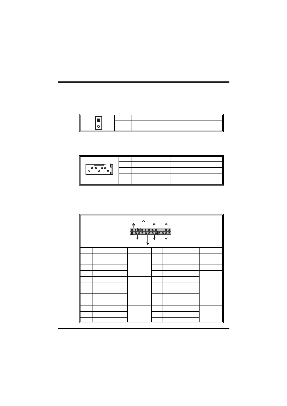
JCL1: Chassis Open Message Header
This connector allows system to monitor PC case open status. If the
signal has been triggered, it will record to the CMOS and show the
message on next boot-up.
1
Pin Assignment
1 Case open signal
2 Ground
S ATA1 ~ SATA4 : Serial ATA Connectors
The motherboard has a PCI to SATA Controller with 2 channels SATA
interface, it satisfies the SATA 1.0 spec and with transfer rate of 1.5Gb/s.
Pin Assignment Pin Assignment
1 Ground 2 TX+
3 TX- 4 Ground
7
1
5 RX- 6 RX+
7 Ground
F r ont Pa n el Conn ect or : JPA NEL 1
This 24-pin connector includes Power-on, Reset, HDD LED, Power LED,
Sleep button, speaker and IrDA Connection. It allows user to connect
the PC case’s front panel switch functions.
PWR_LED
SL P
2
1
SPK
++
HLED
+
On/Off
-
-
Pin Assignment Function Pin Assignment Function
1 +5V 2 Sleep cont rol
3 N/A 4 Ground
5 N/A 6 N/A N/A
Speaker
Connector
7 Speaker
9 HDD LED (+) 10 Power LED (+)
11 HDD LED (-)
13 Ground 14 Power but ton
15 Reset control
Hard driv e
LED
Reset
button
17 N/A 18 Key
19 N/A 20 Key
21 +5V 22 Ground
IrDA
Connector
23 IRTX
IR
24
23
RS T
IR
8 Power LED (+)
12 Power LED (-)
16 Ground
24 IRRX
Sleep
button
Power LED
Power-on
button
IrDA
Connector
16
Page 17
I915P-A 7 PCI-ED
I91PL-A7 PCI-ED
CHAPTER 4: USEFUL HELP
4.1 AWARD BIOS BEEP CODE
Beep Sound Meanin g
One long beep followed by two short
beeps
High-low siren sound CPU overheated
One Short beep when system boot-up No error found during POST
Long beeps every other second N o DRAM detected or install
4.2 EXTRA INFORMATION
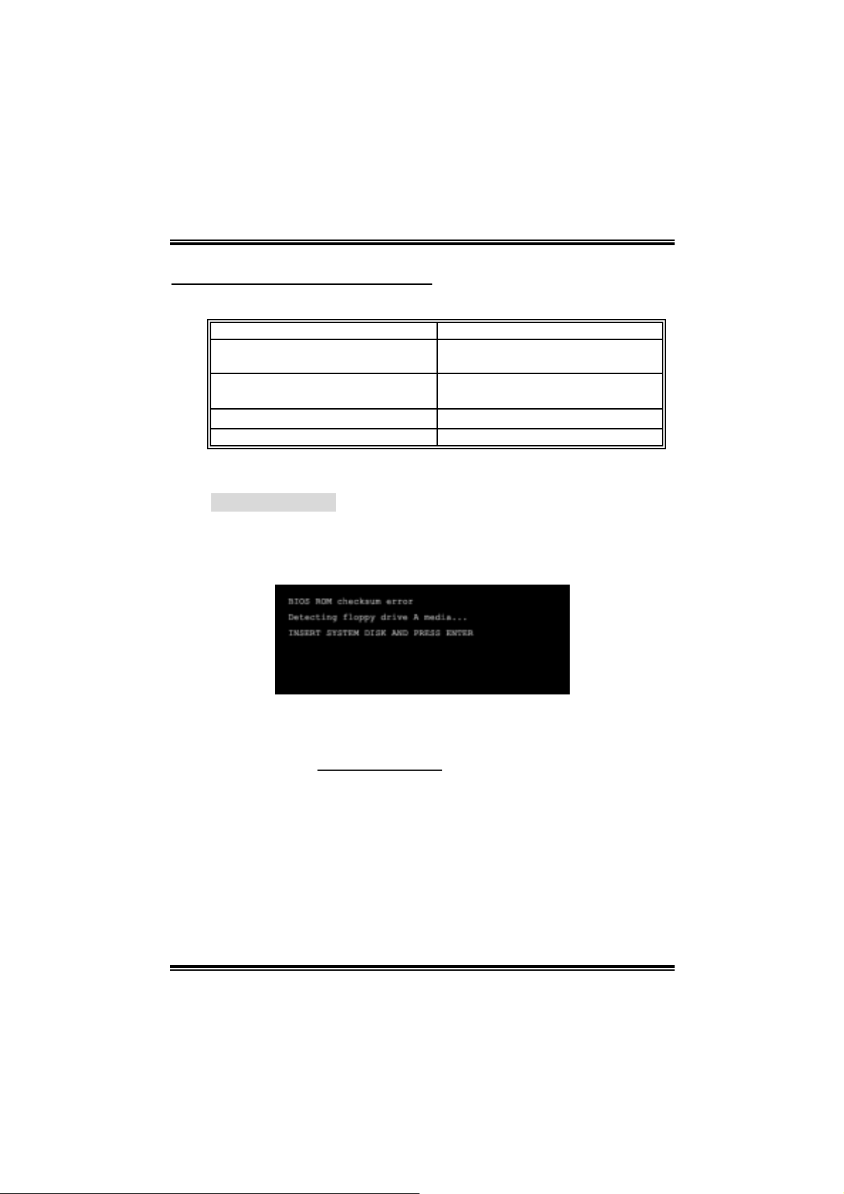
A. BIOS Update
After you fail to update BIOS or BIOS is invaded by virus, the
Boot-Block function will help to restore BIOS. If the following message
is shown after boot-up the system, it means the BIOS contents are
corrupted.
Video card not found or v ideo card
memory bad
System will shut down automat ically
In this Case, please follow the procedure below to restore the BIOS:
1. Make a bootable floppy disk.
2. Download the Flash Utility “AWDFLASH.exe” from the Biostar
website: www.biostar.com.tw
3. Confirm motherboard model and download the respectively BIOS
from Biostar website.
4. Copy “AWDFLASH.exe” and respectively BIOS into floppy disk.
5. Insert the bootable disk into floppy drive and press Enter.
6. System will boo-up to DOS prompt.
7. Type “Awdflash xxxx.bf/sn/p y/ r” in DOS prompt.
8. System will update B IOS automatically and restart.
9. T he BIOS has been recovered and will wo rk properl y.
17
Page 18

I915P-A 7 PCI-ED
I91PL-A7 PCI-ED
B. CPU Overheated
If the system shutdown automatically after power on system for
seconds, that means the CPU protection function has been activated.
When the CPU is over heated, the motherboard will shutdown
automatically to avoid a damage of the CPU, and the system may not
power on again.
In this case, please double check:
1. The CPU cooler surface is placed evenly with the CPU surface.
2. CPU fan is rotated normally.
3. CPU fan speed is fulfilling with the CPU speed.
After confirmed, please follow steps below to relief the CPU protection
function.
1. Remove the power cord from power supply for seconds.
2 . Wa i t fo r se c o nd s.
3. Plug in the power cord and boot up the system.
Or you can:
1. Clear the CMOS data.
(See “Close CMOS Header: JCMOS1” section)
2 . Wa i t fo r se c o nd s.
3. Powe r on the syste m agai n.
18
Page 19

4.3 TROUBLESHOOTING
e
Probable Solution
1. No power to the system at all
Power light don’t illuminate, f an
inside power supply does not turn
on.
2. Indicator light on key board does
not turn on.
System inoperativ e. Keyboard lights
are on, power indicator lights are lit,
and hard driv e is spinning.
System does not boot from hard disk
driv e, can be booted f rom optical driv e.
System only boots f rom optical driv e.
Hard disk can be read and applications
can be used but booting from hard dis k
is impossible.
Screen message says “Invalid
Configuration” or “CMOS Failure.”
Cannot boot system after installing
second hard drive.
I915P-A 7 PCI-ED
I91PL-A7 PCI-ED
1. Make sure power c able is
securely plugged in.
2. Replace cable.
3. Contact t echnical support.
Using even pressure on both ends of
the DIMM, press down firmly until the
module snaps into place.
1. Check cable running from disk to
disk controller board. Make sure
both ends are securely plugged
in ; c h ec k t h e d riv e ty pe i n t h e
standard CMOS setup.
2. Backing up the hard driv e is
extremely important. All hard
disks are c apable of breaking
down at any time.
1. Back up data and applications
files.
2. Ref ormat the hard drive.
Re-install applications and data
using backup disks.
Review sys tem’s equipment. Make sur
correct inf ormation is in setup.
1. Set mast er/slave jumpers
correctly.
2. Run SETUP program and select
correct driv e types. Call the drive
manufacturers f or compatibility
with other drives.
19
Page 20

I915P-A 7 PCI-ED
I91PL-A7 PCI-ED
CHAPTER 5: W ARPSPEEDER™
5.1 INTRO DUCTION
[WarpSpeeder™], a new powerful control utility, features three
user-friendly functions including Overclock Manager, Overvoltage
Manager, and Hardware Monitor.
With the Overclock Manager, users can easily adjust the frequency they
prefer or they can get the best CPU performance with just one click. The
Overvoltage Manager, on the other hand, helps to power up CPU core
voltage and Memory voltage. The cool Hardware Monitor smartly indicates
the temperatures, voltage and CPU fan speed as well as the chipset
information. Also, in the About panel, you can get detail descriptions about
BIOS model and chipsets. In addition, the frequency status of CPU,
memory, AGP and PCI along with the CPU speed are synchronically
shown on our main panel.
Moreover, to protect users' computer systems if the setting is not
appropriate when testing and results in system fail or hang,
[WarpSpeeder™] technology assures the system stability by automatically
rebooting the computer and then restart to a speed that is either the
original system speed or a suitable one.
5.2 SYSTEM REQUIREMENT
OS Support: Windows 98 SE, Windows Me, Windows 2000, Windows XP
DirectX: DirectX 8.1 or above. (The Windows XP operating system
includes DirectX 8.1. If you use Windows XP, you do not need to install
DirectX 8.1.)
20
Page 21

I915P-A 7 PCI-ED
I91PL-A7 PCI-ED
5.3 INST ALL AT ION
1. Execute the setup execution file, and then the following dialog will pop
up. Please click “Next” button and follow the default procedure to
install.
2. When you see the following dialog in setup procedure, it means setup
is completed. If the “Launch the WarpSpeeder Tray Utility” checkbox
is checked, the T ray Icon utility and [WarpSpeeder™] utility will be
automatically and immediately launched after you click “Finish”
button.
Usage:
The following figures are just only for reference, the screen printed in
21
Page 22

I915P-A 7 PCI-ED
I91PL-A7 PCI-ED
thi s user manual will change according to your motherboard on hand.
22
Page 23

I915P-A 7 PCI-ED
I91PL-A7 PCI-ED
5.4 [WARPSPEEDER™] INC LUDES 1 TRAY ICON AND 5 PAN ELS
1. Tray Icon:
Whenever the Tray Icon utility is launched, it will display a li ttle tray
icon on the right side of Windows Taskbar.
This utility is responsible for conveniently invoking [WarpSpeeder™]
Utility. You can use the mouse by clicking the left button in order to
invoke [WarpSpeeder™] directly from the little tray icon or you can
right-click the little tray icon to pop up a popup menu as following
figure. The “Launch Utility” item in the popup menu has the same
function as m o use l eft-cli ck on tray icon and “Exi t” i tem will close
Tray Icon utility i f selected.
23
Page 24

I915P-A 7 PCI-ED
I91PL-A7 PCI-ED
2. Main Panel
If you click the tray i con, [WarpSpeeder™] utility will be i n voked.
Please refer to the following figure; the utility’s first window you will
see is Main Panel.
Main Panel contains feat ures as follows:
a. Display the CPU Speed, CPU external clock, Memory clock,
AGP clock, and PCI clock information.
b. Contains About, Voltage, Overclock, and Hardware Monitor
Buttons for invoking respective panels.
c. With a user-friendly Status Animation, it can represent 3
overclock percentage stages:
Man walking→overclock percentage from 100% ~ 110 %
Panther running→overclock percentage from 110% ~ 120%
Car raci ng→overclock percentage from 120% ~ above
24
Page 25

I915P-A 7 PCI-ED
I91PL-A7 PCI-ED
25
Page 26

I915P-A 7 PCI-ED
I91PL-A7 PCI-ED
3. Vol tage Panel
Cli ck the Voltage button in Main Panel, the button will be highlighted
an d the Voltage Panel will sl ide out to up as the foll owing fig ure.
In this panel, you can decide to increase CPU core voltage and
Memory voltage or not. The default setting is “No”. If you want to get
the best performance of overclocking, we recommend you click the
option “Yes”.
26
Page 27

I915P-A 7 PCI-ED
I91PL-A7 PCI-ED
4. Over clock Pa nel
Cli ck the Overcl ock button in Main Panel, the button will be
highlighted and the Overclock Panel will slide out to left as the
following figure.
Overclock Panel cont ains the these fea tures:
a. “–3MHz button”, “-1MHz button”, “+1MHz button”, and “+3MHz
button”: provide user the ability to do real-time overclock
adjustment.
Warning:
Manually overclock is potentially dangerous, especially when the
ov erclocking percentage is over 110 %. We strongly recommend you
v erify every speed you overc lock by click the Verify button. Or, you can
just click Auto ov erclock button and let [WarpSpeeder™] autom atically
gets the best result f or you.
b. “Recovery Dialog button”: Pop up the following dialog. Let user
select a restoring way if system need to do a fail-safe reboot.
27
Page 28

I915P-A 7 PCI-ED
I91PL-A7 PCI-ED
28
Page 29

I915P-A 7 PCI-ED
I91PL-A7 PCI-ED
c. “Auto-overclock button”: User can click this button and
[WarpSpeeder™] will set the best and stable performance and
frequency automatically. [WarpSpeeder™] utility will execute a
seri es of testing until system fail. Then system will do fail -safe
reboot by using Watchdog function. After reboot, the
[WarpSpeeder™] utility will restore to the hardware default
setting or load the verified best and stable frequency according
to the Recovery Dialog’s setting.
d. “Verify button”: User can click this button and [WarpSpeeder™]
will proceed a testing for current frequency. If the testing is ok,
then the current frequency will be saved into system registry. If
the testing fail, system will do a fail-safe rebooting. After reboot,
the [WarpSpeeder™] utili ty will restore to the hardware default
setting or load the verified best and stable frequency according
to the Recovery Dialog’s setting.
Note:
Because the testing programs, invok ed in Auto-overclock and Verify,
include DirectDraw, Direct3D and DirectShow tests, the Direct X 8.1 or
newer runtime library is required. And please make sure your display
card’s color depth is High color (16 bit) or True color( 24/32 bit ) that is
required f or Direct3D rendering.
5. Hardware Monitor Panel
Cli ck the Ha rdware Moni tor button in Main Panel, the button will be
highlighted and the Hardware Monitor panel will slide out to left as
the following figure.
In this panel, you can get the real-time status information of your
sy stem. The i nformatio n will be refreshed every 1 second.
29
Page 30

I915P-A 7 PCI-ED
I91PL-A7 PCI-ED
30
Page 31

I915P-A 7 PCI-ED
I91PL-A7 PCI-ED
6. About Panel
Click the “about” button in Main Panel, the button will be highlighted
and the About Panel will slide out to up as the following figure.
In this panel, you can get model name and detail information in hints
of all the chipset that are related to overclocking. You can also get
the mainboard’s BIOS model and the Version number of
[WarpSpeeder™] utility.
31
Page 32

I915P-A 7 PCI-ED
I91PL-A7 PCI-ED
32
Page 33

I915P-A 7 PCI-ED
I91PL-A7 PCI-ED
Note:
Because the overclock, overvoltage, and hardware monitor features
are controlled by several separate chipset, [WarpSpeeder™] divide
these features to separate panels. If one chipset is not on board, the
co rre l ati ve bu t to n in Mai n pan el will be di sabl ed, bu t wil l not i n te rf e re
other panels’ functions. This property can make [WarpSpeeder™]
utility more ro bust.
03/24, 2005
33
Page 34

I915P-A7 PCI-ED & I91PL-A7 PC I-ED
BIOS SETUP
BIOS Setup ........................................................................ 1
1 Main Menu .....................................................................................................3
2 Standard CMOS Features ..............................................................................6
3 Advanced BIOS Features............................................................................... 9
4 Advanced Chipset Features..........................................................................14
5 Integrated Peripherals .................................................................................. 16
6 Power Management Setup ........................................................................... 21
7 PnP/PCI Configurations ...............................................................................26
8 PC Health Status ..........................................................................................28
9 Frequency/ Voltage Control......................................................................... 29
i
Page 35

I915P-A7 PCI-ED & I91PL-A7 PCI-ED BIOS Manual
BIOS Setup
Introduction
T his m anua l disc ussed Aw ard™ S etup program built into the ROM BIOS. The Setup pro gram
allows users to modify the basic system configuration. This special information is then stored
in ba tter y-b acked R AM s o tha t it re tains the S etup inf orma tion w h en th e power is turned o ff.
The Award BIOS™ installed in your computer system’s ROM (Read Only Memory) is a
custom version of an industry standard BIOS. T his means that it supports Intel Pentium
pr oces sor inp ut/ outp ut sy stem . T he BI OS pr ovides c ritica l low-le ve l support for sta ndard
devices such as disk drives and serial and paralle l ports.
Adding important has customized the Award BIOS™, but nonstandard, features such as virus
and password protection as well as special support for detailed fine-tuning of the ch ipset
controlling the entire system.
The rest of this manual is intended to guide you through the process of configuring your
system using Setup.
Plug and Pla y Suppo rt
These AWARD BIOS supports the Plug and Play Version 1.0A specification. ESCD
(Exten ded S ystem Co nfigurat ion Data) w rite is sup ported.
EPA Green PC Support
This AWARD BIOS supports Version 1.03 of the EPA Green PC specification.
APM Support
These AWARD BIOS supports Version 1.1&1.2 of the Advanced Power Management (APM)
specification. Power management features are implemented via the System Management
Interrupt (SMI). Sleep and Suspend power management modes are supported. Power to the
hard disk drives and video monitors can be managed by this AWARD BIOS.
ACP I S uppo rt
Award ACPI BIOS support Version 1.0 of Advanced Configuration and Power interface
specification (ACPI). It provides ASL code for power management and device
configuration capabilities as defined in the ACPI specification, developed by Microsoft, Intel
and Toshiba.
®
4
1
Page 36

I915P-A7 PCI-ED & I91PL-A7 PCI-ED BIOS Manual
PCI Bus Support
This AWARD BIOS also supports Version 2.1 of the Intel P CI (Peripheral Component
Interconnect) local bus specification.
DRAM S uppo rt
DDR SDRAM (Double Data Rate Synchronous DRAM) are supported.
Supported CPUs
This AWARD BIOS supports the Intel CPU.
Usi ng Se tup
In general, you use the arrow keys to highlight items, press <Enter> to select, use the <PgUp>
and <PgDn> keys to change entries, press <F1> for help and press <Esc> to quit. The
following table provides more detail about how to navigate in the Setup program by using the
keyboard.
Keystroke Function
Up arro w Move to p revious item
Down arrow Move to ne xt item
Left arrow Move to the item on the left (me nu bar)
Right arrow Move to the item on the right (menu bar)
Move E nter Move to the item yo u desi red
PgUp key Increase the numeric value or make changes
PgDn key Decrease the numeric value or make changes
+ Key Increase the numeric value or make changes
- Key Decrease the numeric value or make changes
Esc key Main Menu – Quit and not save changes into CMOS
F1 key Genera l he lp o n Set up na viga tio n ke ys
F5 key Load previous values from CMOS
F7 key Load the optimized defaults
F10 key Save all the CMOS changes and exit
Status Page Setup Menu and Option Page Setup Menu – Exit
Current page and return to Mai n Menu
2
Page 37

I915P-A7 PCI-ED & I91PL-A7 PCI-ED BIOS Manual
1 Main Menu
Once you enter Award BIOS™ CMOS Setup Utility, the Main Menu will appear on the
screen. T he Main Menu allows you to select from several setup functions. Use the arrow keys
to select among the items and press <Enter> to accept and enter the sub-menu.
!! WARNING !!
The information about BIOS defaults on manual (Figure
1, 2,3, 4,5,6,7,8, 9) is just for reference, please refer to the BIOS
installed on board, for update information.
Figure 1. Main Menu
Standard CMOS Features
This submenu contains industry standard configurable options.
Advanced BIOS Features
This submenu allows you to configure enhanced features of the BIOS.
Advanced Chipset Features
This submenu allows you to configure special chipset features.
3
Page 38

I915P-A7 PCI-ED & I91PL-A7 PCI-ED BIOS Manual
Integrated Peripherals
This submenu allows you to configure certain IDE hard drive options and Programmed Input/
Output features.
Power Management Setup
This submenu allows you to configure the power management features.
PnP/PCI Configurations
This submenu allows you to configure certain “Plug and Play” and PCI options.
PC Hea lth Status
This submenu allows you to monitor the hardware of your system.
Freque ncy/ Voltage Control
This submenu allows you to change CPU Vcore Voltage and CPU/PCI clock. (However, this
funct ion is stro ngly recommen ded not to use. No t pro perly ch ange the vol ta ge and
clock may cause the CPU o r M/B damage!)
Load Optimi ze d Defaults
This selection allows you to reload the BIOS when the system is havin g problems particularly
with the boot sequence. These configurations are factory settings optimized for this system.
A confirmation message will be displayed before defaults are set.
Set Supe rviso r Passwor d
Setting the supervisor password will prohibit everyone except the supervisor from making
changes using the CMOS Setup Utility. You will be prompted with to enter a password.
4
Page 39

I915P-A7 PCI-ED & I91PL-A7 PCI-ED BIOS Manual
Set User Password
If the Supervisor Password is not set, then the User Password will function in the same way as
th e Supe rviso r Password . If the Su per visor P asswor d is set a nd the Use r P asswor d is set,
the “User” will only be able to view conf igurations but will not be able to change them.
Save & Exit Se t up
Save all configuration changes to CMOS(memory) and exit setup. Confirmation message will
be displayed before proceeding.
Exi t Wi thout Sa ving
Abandon all changes made during the current session and exit setup. confirmation
message will be displayed before proceeding.
Upgrade BIOS
This submenu allows you to upgrade bios.
5
Page 40

I915P-A7 PCI-ED & I91PL-A7 PCI-ED BIOS Manual
2 Standard CMOS Features
The items in Standard CMOS Setup Menu are divided into 10 categories. Each category
includes no, one or more than one setup items. Use the arrow keys to highlight the item and
then use the<PgUp> or <PgDn> keys to select the value you want in each item.
Figure 2. Standard CMOS Setup
6
Page 41

I915P-A7 PCI-ED & I91PL-A7 PCI-ED BIOS Manual
Main Menu Selec tio ns
This table shows the selections that you can make on the Main Menu.
Item Options Description
Date mm : dd : yy Set the system date. Note
Time hh : mm : ss Set the system internal
IDE Primary Master Options are in its sub
menu.
IDE Pri mar y Slave Options are in its su b
menu.
IDE Secondary Master Options are in its sub
menu.
IDE Secondary Slave Options are in its sub
menu.
Drive A
Drive B
Video E GA/ VGA
360K, 5.25 in
1.2M, 5.25 in
720K, 3.5 in
1.44M, 3.5 in
2.88M, 3.5 in
None
CGA 40
CGA 80
MONO
that the ‘Day’ automatically
changes when you set the
date.
clock.
Press <Enter> to enter the
sub men u of det aile d
options
Press <Enter> to enter the
sub men u of det aile d
options.
Press <Enter> to enter the
sub men u of det aile d
options.
Press <Enter> to enter the
sub men u of det aile d
options.
Select the type of floppy
disk drive installed in your
system.
Select the default video
device.
7
Page 42

I915P-A7 PCI-ED & I91PL-A7 PCI-ED BIOS Manual
Item Options Description
Halt On All Errors
No Errors
All, but Keyboard
All, but Diskette
All, but Disk/ Key
Base Memory N/A Displays the amount of
Extended Memory N/A Displays the amount of
Total Memory N/A Displays the total memory
Select the situation in which
you want the BIOS to stop
the POST process and
notify you.
conventional memory
detected during boot up.
extended memory detected
during boot up.
available in the system.
8
Page 43

I915P-A7 PCI-ED & I91PL-A7 PCI-ED BIOS Manual
3 Advanced BIOS Features
Fig ure 3. Adva nced BIOS Se t up
CP U F E ATUR E
Delay Prior to Thermal
Set this item to enable the CP U Thermal function to engage after the specified
time.
The Choices: 4, 8, 16 (default), 32.
9
Page 44

I915P-A7 PCI-ED & I91PL-A7 PCI-ED BIOS Manual
Thermal Manageme nt
Allow you to choose the thermal management method of your monitor.
The Choices:Thermal Monitor 1 (de fault ), Th ermal Monito r2.
Notes:The choices will be different according to your CPU features.
TM2 B us Ratio
Represents the frequency. Bus ratio of the throttled performance state that will
be initiated when the on-die sensor goes from not hot to hot.
The Choices: 0X (default).
TM2 Bus VID
Re pres ents the voltage o f the thro ttled perf ormance state that wil l be init iated
when the on-die sensor goes from not hot to hot.
The Choices:0.8375 (default).
Limit CPU ID Max Val
Set limit CPU ID maximum vale to 3, it should be disabled for Win XP.
The Choices: Disabled (default), Enabled.
Execute Disable Bit
The Choices: Enabled Disabled (default), Disabled.
HARD DISK BOOT PRIORITY
These BIOS attempt to load the operating system from the device in the sequence select
in these items.
The Cho ices: Pri. Master, Pri. Slave, Sec. Master, Sec. Slave, USBHDD0, BHDD1,
USBHDD2 and Bootable Add-in Cards.
10
Page 45

I915P-A7 PCI-ED & I91PL-A7 PCI-ED BIOS Manual
BOO T SE Q & F LOP P Y SET UP
Virus Warning
First/Seco nd/T hird/Boo t Other Device
These BIOS attempt to load the operating system from the device in the
sequence selected in these items.
The Ch o ice s: Floppy, LS120, HDD-0, SCSI, CDROM, HDD-1, HDD-2,
HDD-3, ZIP100, LAN, HPT370, Disabled, Enabled.
Swap Floppy Drive
For systems with two floppy drives, this option allows you to swap logical
drive assignments.
The Choices: Disabled (default), Enabled.
Boot Up Floppy Seek
Enabling this option will test the floppy drives to determine if they Have 40 or
80 tracks. Disabling this option reduces the time it takes to boot-up.
The Ch o ice s: Disabled, En a bl ed (defau
Report NO FDD for Win95
The Ch o ice s: NO (default).
This option allows you to choose the Virus Warning feature that is used to protect
the IDE Hard Disk boot sector. If this function is enabled and an attempt is made to
write to the boot sector, BIOS will display a warning message on the screen and sound an
alarm beep.
Disabled (default) Virus protection is disabled.
Enabled Virus protection is activated.
11
Page 46

I915P-A7 PCI-ED & I91PL-A7 PCI-ED BIOS Manual
CPU L3 Cache
Depending on the CPU/chipset in use, you may be able to increase
memory access time with this option.
Enable d (default) Enable cache.
Disabled Disable cache.
HYPER-THREADING TECHNOLOGY
This option allows you to enable or disabled CPU Hyper-Threading.
Enabled for Windows XP and Linux 2.4.x (OS optimized for Hyper
Threading Technology. Disabled for other OS (OS not optimized for
Hyper Threading Technology.
The Choices: Enabled (Default), Disabled.
QUIC K POWER ON S E LF TEST
Enabling this option will cause an abridged version of the P ower On
Self-Test (POST) to execute after you power up the computer.
Disabled Normal POST.
Enable d (default) Enable quick POST.
BOO T UP N UM LOC K ST ATUS
Selects the NumLock. State after power on.
On (default) Numpad is number keys.
Off Numpad is arrow keys.
GATE A20 OPTION
Se lect if c h ips et or keybo ard c ontr oller s hou ld control Ga te A20.
Normal A pin in the keyboard controller controls GateA20.
Fast (defau lt) Le ts ch ipset cont rol G ate A20.
TYPEMATIC RATE SETTING
When a key is held down, the keystroke will repeat at a rate determined by
the keyboard controller. When enabled, the typematic rate and typematic
delay can be configured.
The Choices: Disabled (defau lt), E nable d.
TYPEMATIC RATE (CHARS/SEC)
Sets the rate at which a keystroke is repeated when you hold the keydown.
The Choices: 6 (default), 8,10,12,15,20,24,30
TYPEMATIC DELAY (MSEC)
Sets the delay time after the key is held down before it begins to repeat
the keystroke.
The Choices: 250 (default), 500, 750, and 1000.
12
Page 47

I915P-A7 PCI-ED & I91PL-A7 PCI-ED BIOS Manual
SECURITY OPTION
This option will enable only individuals with passwords to bring the system
online and/or to use the CMOS Setup Utility.
System A password is required for the system to boot and is also required to access the
Setup Utility.
Setup (default) A password is required to access the Setup Utilityonly.
This will only apply if passwords are set from the Setup main menu.
APIC MODE
Selecting Enabled enables APIC device mode reportin g from the BIOS to
the operating system.
The Choices: Enabled (default), Disabled.
MPS VERSION CONTROL FOR OS
The BIOS supports version 1.1 and 1.4 of the Intel multiprocessor
sp ecif ication.
Select version supported by the operation system running on this
computer.
The Choices: 1.4 (default), 1.1.
OS SELECT FOR DRAM > 64MB
A choice other than Non-OS2 is only used for OS2 systems with memory
exceeding 64MB.
The Choices: Non-OS2 (default), OS2.
SMALL LOGO (EPA) SHOW
This item allows you to select whether the “Small Logo” shows.
Enable d (default) “Small Logo” shows when system boot up.
Disabled No “Small Logo” shows when system boots up.
SUMMARY SCREEN SHOW
This item allows you to enable/disable the summary screen. Summary
screen means system configuration and PCI device listing.
The choices: E n abl e d , Disabled (default).
13
Page 48

I915P-A7 PCI-ED & I91PL-A7 PCI-ED BIOS Manual
4 Advanced Chipset Features
This submenu allows you to configure the specific features of the chipset installed on your system.
This chipset manage bus speeds and access to system memory resources, such as DRAM. It also
coordinates communications with the PCI bus. The default settings that came with your system
have been optimized and therefore should not be changed unless you are suspicious that the
settings have been changed incorrectly.
Figure 4. Advanced Chipset Setup
DRAM TIM ING SELE CTABLE
When synchronous DRAM is installed, the number of clock cycles of CAS
latency depends on the DRAM timing.
The Ch o ice s: By S PD (default), Manual.
CAS LATENCY TIME
When synchronous DRAM is installed, the number of clock cycles of CAS
latency depends on the DRAM timing.
The Choices: Auto (default).
DRAM RAS# TO CAS# DELAY
This field let you insert a tim ing delay between the CAS and RAS strobe
signals, used when DRAM is written to, read from, or refreshed. Fast gives
faster performance; and slow gives more stable performance. This field
applies only when synchronous DRAM is installed in the system.
The Choices: Auto (default).
14
Page 49

I915P-A7 PCI-ED & I91PL-A7 PCI-ED BIOS Manual
DRAM RAS# PRECHARGE
If an insufficient number of cycles is allowed for RAS to accumulate its
charge before DRAM refresh, the refresh may be incomplete, and the
DRAM may fail to retain data. Fast gives faster performance; and Slow
gives more stable performance. This field applies only when synchronous
DRAM is ins ta lled in the sys tem.
The Choices: Auto (default).
PRECHARGE DELAY (TRAS)
This item controls the number of DRAM clocks to activate the precharge
delay.
The Choices: Auto (default).
SYSTEM MEMORY FREQUENCY
This item allows you to select the Memory Frequency.
The Choices: Auto (default), DDR266, DDR300, and DDR400.
SLP_S4# ASSERTION WIDTH
This item sets the minimum assertion width of the SLP-S4# signal to
guarantee the DRAM has been safely power-cycled.
SYSTEM BIOS CACHEABLE
Selecting Enabled allows you caching of the system BIOS ROM at
F0000h~FFFFFh, resulting a better system performance. However, if any
program writes to this memory area, a system error may result.
The Ch o ice s: En a ble d (default), Disabled.
VIDEO BIOS CACHEABLE
Select Enabled allows cachin g of the video BIOS, resulting a better
system performance. However, if any program writes to this memory area,
a system error may result.
The Choices: Disabled (default), Enabled.
MEMORY HOLE AT 15M-16M
You can reserve this area of system memory for ISA adapter ROM. When
this area is reserved it cannot be cached. The user information of
peripherals that need to use this area of system memory usually2
discussed their memory requirements.
The Choices: Disabled (default), Enabled.
15
Page 50

I915P-A7 PCI-ED & I91PL-A7 PCI-ED BIOS Manual
5 Integrated Peripherals
Figure 5. Integrated Peripherals
OnChip IDE Device
IDE HDD Block Mode
Block mode is also called block transfer, multiple commands, or
multiple sector read / write. If your IDE hard drive supports block mode
(most new drives do), select Enabled for automatic detection of the
optimal number of block mode (most new drives do), select Enabled
for automatic detection of the optimal number of block read / write per
sector where the drive can support.
The Ch o ice s: En a ble d (default), Disab led.
16
Page 51

I915P-A7 PCI-ED & I91PL-A7 PCI-ED BIOS Manual
IDE DMA Transfer Access
This item allows you to enable or disable the IDE transfer access.
The Ch o ice s: En a ble d (default), Disabled.
On-chip Primary PCI IDE
IDE Primary/Secondary/Master/Sla ve PIO
On-chip Secondary PCI IDE
IDE Primary/Secondary/Master/Sla ve UDMA
On-Chip Serial ATA Setting
This item allows you to enable or disable the primary/ secondary IDEChannel.
The Ch o ice s: En a ble d (Default), Disabled.
The IDE PIO (Programmed Input / Output) fields let you set a PIO
mode (0-4) for each of the IDE devices that the onboard IDE interface
supports. Modes 0 to 4 will increase performance progressively. In
Auto mode, the system automatically determines the best mode for
each device.
The Choices: Auto (default), Mode0, Mode1, Mode2, Mode3, and
Mode4.
This item allows you to enable or disable the primary/ secondary IDEChannel.
The Ch o ice s: En a ble d (Default), Disabled.
Ultra DMA/100 functionality can be implemented if it is supported by
the IDE hard drives in your system. As well, your operating
environment requires a DMA driver (Windows 95 OSR2 or a third
party IDE bus master driver). If your hard drive and your system
software both support Ultra DMA/100, select Auto to enable BIOS
support.
The Choices: Auto (default), Disabled.
This item allows you to choose:
Disabled: disabled SATA Controller
Combine d Mode: PATA and SATA are combined max of 2 IDE drivers
in each channel.
Enhanced Mo de: enabled both SAT A and PATA max of 6 IDE drivers
are supported.
SATA O nly: SAT A is operatin g in le gac y mode .
The Choices: Default (default), Auto, Combined Mode, Enhanced
Mode, and SATA only.
17
Page 52

I915P-A7 PCI-ED & I91PL-A7 PCI-ED BIOS Manual
ONBO ARD DE VICE
PCI Express Root Port Func,
PCI Express Port
This item allows you to select the PCI Express Port.
The Choices: Auto (default), Enabled, Disabled.
PCI-E Compliancy Mode
T his ite m allows you t o sele ct th e P CI-E Complian cy Mode .
The Choices: v1.0a (default), v1.0.
U SB Co nt ro lle r
Select Enabled if your system contains a Universal Serial Bus (USB) controller
and you have USB peripherals.
The Choices: Enabled (default), Disabled
USB 2.0 Controller
This entry is to enabled/ disabled EHCI controller only. This BIOS itself may/may not
have high speed USB support. If the BIOS has high speed USB support built in, the
support will automatically turn on, when high speed device were attached.
The Choices:Enabled(default).
USB Ke yboa r d Suppo rt
This item allows you to enable or disable the USB Keyboard Legacy Support.
Enable d (default) Enable USB Keyboard Support.
Disabled Disable USB Keyboard Support.
18
Page 53

I915P-A7 PCI-ED & I91PL-A7 PCI-ED BIOS Manual
USB Mouse Support
This item allows you to enable or disable the USB Mouse Legacy Support.
Enabled Enable USB Mouse Support.
Disabled (default) Disable USB Mouse Support.
This item allows you to decide to enable/ disable to support AC97 Aud io.
The Choices: Auto (default), Disabled.
AC97 Audio
Onboard RAID <ITE8211>
The C ho ices: Enable d (default), Disabled.
Onboa rd RAID BIOS
The Choices: Disabled (default), Enabled.
Onboard 1394
The C ho ices: Enable d (default), Disabled.
Onboa rd LAN
This item allows you to enable or disable the Onboard LAN.
The C ho ices: Enable d (default), Disabled.
Onboa rd LAN Bo o t ROM
This item allows you to enable or disable the Onboard LAN Boot ROM.
The Choices: Disabled (default), Enabled.
Supe r IO Device
If you highlight the literal “Press Enter” next to the “
press the enter key, it will take you a submenu with the following options:
19
Super IO Device” labe l and then
Page 54

I915P-A7 PCI-ED & I91PL-A7 PCI-ED BIOS Manual
Onboa rd FDC Co ntroller
Select Enabled if your system has a floppy disk controller (FDC) installed on the system
board and you wish to use it. If install and FDC or the system has no floppy drive, select
Dis ab le d in this f ield.
The C ho ices: Enable d (default), Disabled.
Onboard Serial Port 1
Select an address and corresponding interrupt for the first and second serial ports.
The Choices:Disabled, 3F8/IRQ4 (defau lt), 2F8/IRQ3, 3E8/IRQ4, 2E8/IRQ3, Auto.
O n boa rd IR F u nc tio n
The Choices: Disabled (default), Enabled.
UART Mode Select
This item allows you to determine which Infra Red (IR) function of onboard I/O chip.
The Choices: Normal, AS KIR, IrDA(default).
UR2 Duplex Mode
Select the value required by the IR device connected to the IR port. Full-duplex mode
permits simultaneous two-direction transmission. Half-duplex mode permits transmission
in one direction only at a time.
The Choices: Half (d efau lt), Fu ll.
Onboa rd Pa rallel Port
This item allows you to determine access onboard parallel port controller with which I/O
Address.
The Choices:378/IRQ7 (default), 278/IRQ5, 3BC/IRQ7, Disabled.
Parallel Port Mode
The default value is SPP.
The Choices:
SPP(de fault ) Usin g P arallel port as Stan dard Print er P ort.
EP P Us ing P aralle l P o rt as Enhanc ed Par allel P ort .
EC P Us in g P aralle l por t as E xte nded Capab ilities Port.
EC P+EPP Us ing P ar allel p ort a s ECP & EP P mode.
ECP M ode Use DM A
Select a DMA Channel for the port.
The Choices: 3 (d efault), 1.
20
Page 55

I915P-A7 PCI-ED & I91PL-A7 PCI-ED BIOS Manual
6 Power Management Setup
The Power Management Setup Menu allows you to configure your system to utilize energy
conservation and power up/power down features.
Figure 6. Power Ma nage ment Se tup
ACPI & W AKE UP EVENT S
ACPI Func tion
This item displays the status of the Advanced Configuration and Power Management
(ACPI).
The Ch o ice s: En a ble d (default), Disabled.
21
Page 56

I915P-A7 PCI-ED & I91PL-A7 PCI-ED BIOS Manual
ACPI Suspe nd T ype
The item allows you to select the suspend type under the ACPI operating system.
The Choices: S1 (POS) (default) Power on Suspend
S3 (STR) Suspend to RAM
S1 & S3 POS+STR
Run VGABIOS if S3 Resume
Choosing Enabled will make BIOS run VGA BIOS to initialize the VGA card when
system wakes up from S3 state. The system time is shortened if you disable the function,
but system will need AG P driver to init ialize the card. So, if the AGP driver of the VGA
card does not support the initialization feature, the display may work abnormally or not
function after S3.
The Choices: Auto (default), Yes, No.
Wake-Up by PCI card
When you select “Enable”, a PME signal from PCI card returns the system to Full On state.
The Ch o ice s: Enabled, Disabled (default).
Power On by Ring
An input signal on the serial Ring Indicator (RI) line (in other words, an incoming call on
the modem) awakens the system from a soft off state.
The Ch o ice s: Enabled, Disabled (default).
USB KB/MS Wake-Up From S3
This item allows you to enable or disabled USB keyboard wake up from S3.
The Choices: Disabled (Default), Enabled.
Resume by Ala r m
This function is for setting date and time for your computer to boot up. During Disabled,
you cannot use this function. During Enabled,Choose the Date and Time.
Date (of Month) Alarm
You can choose which month the system will boot up.
Time (hh:mm:ss) Alarm
You can choose shat hour, minute and second the system will boot up.
Note: If you have change the setting, you must let the system boot up until it goes to
the operating system, before this function will work.
POWE R ON Func tion
This item allows you to choose the power on function.
The Choices: Button Only(defau lt), P ass word , Hot K ey, Mouse Lef t, Mouse Right, Any
Key, Keyboard 98.
KB POWER ON Password
Input password and press Enter to set the Keyboard power on password.
22
Page 57

I915P-A7 PCI-ED & I91PL-A7 PCI-ED BIOS Manual
Hot Ke y Powe r ON
Input password and press Enter to set the Keyboard power on password.
The Choices: Ctrl- F1 (default), Ctrl-F2, Ctrl-F3, Ctrl-F4, Ctrl-F5,Ctrl-F6, Ctrl-F7, Ctrl-F8,
Ctrl-F9, Ctrl-F10, Ctrl-F11, and Ctrl-F12.
POWER After PWR-Fail
This setting specifies whether your system will reboot after a power fail or interrupts
occurs.
Off Leaves the computer in the power off state.
On Reboots the computer.
Former-Sts Restores the system to the status before power failure or interrupt occurs.
The Choices: Off (default), On, Former-Sts.
RELOAD TIMER EVENTS
Primary/Secondary IDE 0/1
You can select to enable or disable Primary or Secondary RAID 0 or
RAID 1 function under this item.
The Choices: Disabled (defau lt), E nable d.
FDD, COM, LPT Port
You can select to enable or disable FDD, COM, and LPT port under
th is item.
The Choices: Disabled (defau lt), E nable d.
PCI PIRQ [A-D]#
You can select to enable or disable PCI PIRQ [A-D]# under this item.
The Choices: Disabled (default), Enabled.
23
Page 58

I915P-A7 PCI-ED & I91PL-A7 PCI-ED BIOS Manual
Power Manage ment
This category allows you to select the type (or degree) of power saving and is directly
rela ted t o the follow ing mod es:
1.HDD Power Down.
2.Suspe nd Mo de.
There are four options of Power Management, three of which have fixed mode settings
Min. Power Saving
Minimum power management.
Suspend Mode = 1 hr.
HDD Powe r D own = 15 min
Max. Power Saving
Maximum power management only available for sl CPU’s.
Suspend Mode = 1 min.
HDD Powe r D own = 1 min.
Us e r De fi n e (default)
Allows you to set each mode individually.
When not disabled, each of the ranges are from 1 min. to 1 hr. except for HDD Power
Down which ranges from 1 min. to 15 min. and disable.
Video Off Method
This option determines the manner in which the monitor is goes blank.
The Ch o ice s:
VIDEO OFF IN SUS PEND
DPMS (default)
This determines the manner in which the monitor is blanked.
The Choices: Yes (default), No.
SUSPEND TYPE
Select the Suspend Type.
The Choices: Stop Grant (default).
Modem Use IRQ
Th is det ermine s the IRQ, which c an be ap plied in MO DE M use .
The Ch o ice s: 3 (default),4 / 5 / 7 / 9 / 10 / 11 / NA.
24
Page 59

I915P-A7 PCI-ED & I91PL-A7 PCI-ED BIOS Manual
Sus pe nd M ode
The item allows you to select the suspend type under ACP I operating system.
The Choices: Disabled (default), 1 Min, 2 Min, 4 Min, 6 Min, 8 Min, 10 Min, 20 Min, 30
Min, 40 Min, 1 Hour.
This selection will cause the system to turn off the vertical and horizontal synchronization
ports and write blanks to the video buffer.
Blank Screen
This option only writes blanks to the video buffer.
HDD P owe r Dow n
When enabled, the hard disk drive will power down and after a set time of system inactivity.
All other devices remain active.
The Choices: Disabled (default), 1 Min, 2 Min, 3 Min, 4 Min, 5 Min, 6 Min, 7 Min, 8 Min,
9 Min, 10 Min, 11 Min, 12 Min, 13 Min, 14 Min, 15Min.
Soft-Off by PWR-BT N
Pressing the power button for more than 4 seconds forces the system to enter the
Soft-Off state when the system has “hung.”
The Choices: Delay 4 Sec, Instant-Off (default).
system is not live, system will remain powered off.
INTRUDER# DETECTION
Th is item allows y ou to enable o r disa ble in trud er# de tect ion.
The Choices: Disabled (Default), Enabled.
25
Page 60

I915P-A7 PCI-ED & I91PL-A7 PCI-ED BIOS Manual
7 PnP/PCI Configurations
This section describes configuring the PCI bus system. PCI, or Personal Computer
Interconnect, is a system which allows I/O devices to operate at speeds nearing the speed of
th e CP U itself use s whe n commu n icat in g w ith it s own s pecial compo nents. Th is sec tion
covers some very technical items and it is strongly recommended that only experienced users
should make any chan ges to the default s ettings.
Figure 7. PnP/PCI Configurations
INIT DISPLAY FI RST
This item allows you to decide t o ac tive wheth er P CI Slot or on-chip VGA
first.
The Choices: Onboard/ AGP, PCI Slot(default).
RES O UR CES CO NTROLLED BY
By Choosing “Auto (ESCD)” (default), the system BIOS will detect the
system resources and automatically assign the relative IRQ and DMA
channel for each peripheral. By Choosing “Manual”, the user will need to
assign IRQ & DMA for add-on cards. Be sure that there are no IRQ/DMA
and I/O port conflicts.
26
Page 61

I915P-A7 PCI-ED & I91PL-A7 PCI-ED BIOS Manual
IRQ RESOURCES
T his su bm enu w ill a l low you t o ass ign each system interrupt a type,
depending on the type of device using the interrupt. When you press the
“Press Enter” tag, you will be directed to a submenu that will allow you to
configure the system interrupts. This is only configurable when
“Resources Controlled By” is set to “Manual”.
IRQ-3 assigned to PCI Device
IRQ-4 assigned to PCI Device
IRQ-5 assigned to PCI Device
IRQ-7 assigned to PCI Device
IRQ-9 assigned to PCI Device
IRQ-10 assigned to PCI Device
IRQ-11 assigned to PCI Device
IRQ-12 assigned to PCI Device
IRQ-14 assigned to PCI Device
IRQ-15 assigned to PCI Device
PCI / VG A PALE TT E SNOOP
Choose Disabled or Enabled. Some graphic controllers that are not VGA
compatible take the outp ut fro m a VGA con trol ler and map it to their
display as a way to provide boot information and VGA compatibility.
However, the color information coming from the VGA controller is drawn
from the palette table inside the VGA controller to generate the proper
colors, and the graphic controller needs to know what is in the palette of
the VGA controller. T o do this, the non-VGA graph ic controller watch for
the Write access to the VGA palette and registers the snoop data. In PCI
based systems, w here the VGA con tr ol ler is on the PCI bus and a
non-VGA graphic controller is on an ISA bus, the Write Access to the
palette will not show up on the ISA bus if the PCI VGA controller resp onds
to the Write.
In this case , the PCI VGA controller should not respond to the Write, it
should only snoop the data and permit the access to be forwarded to the
ISA bus. The non-VGA ISA graphic controller can then snoop the data on
the ISA bus. Unless you have the above situation, you should disable
this option.
Disabled (default) disable the function.
Enabled Enable the function.
PCI EXPRESS RELATIVE ITEMS
Maximum Payload Size
Set the maximum payload size for Transaction packets (TLP ).
The Choice: 4096 (default.)
27
Page 62

I915P-A7 PCI-ED & I91PL-A7 PCI-ED BIOS Manual
8 PC Health Status
Figure 8. PC Health Status
Shutdown Temperature
This item allows you to set up the CPU shutdown Temperature. This item only effective
under Windows 98 ACPI mode
The Choices: 60
OC/140O F, 65OC/149OF, 70OC/158OF, Disabled (default).
Show H/W Mo nitor in POST
If you computer contain a monitoring system, it will show PC health status during POST
stage. The item offers several delay time to select you want.
The Choices: Enabled (default), Disabled .
CPU Vcore, NB/SB Voltage +3.3V, +5.0V, 5V (SB), Voltage Battery
Detect the system’s voltage status automatically.
Current CPU Temp
This field displays the current temperature of CPU.
Current CPU FAN Speed
This field displays the current speed of CPU fan.
Current SYS FAN Speed
This field displays the current speed SYSTEM fan.
28
Page 63

I915P-A7 PCI-ED & I91PL-A7 PCI-ED BIOS Manual
9 Frequency/ Voltage Control
Figure 9. Frequency/ Voltage Control
CPU CLOCK RATIO
The Choices: 8X (default), 9X, 10X, 11X, 12X, 13X, 14 X, 15X, 16X, 17X,
18X, 19X, 20 X, 21 X, 22 X, and 23X.
CPU Voltag e Reg ulato r
T his ite m allows you t o select CPU Voltage Re gula tor
The Choices: Default (default).
DDR Voltage Reg ulator
T his ite m allows you t o select DDR Volta ge Re gu la tor
The Choices: Default (Default).
AUTO DETECT PCI CLK
This item allows you to enable / disable auto Detect PCI Clock.
The Choices: Enabled (default), Disabled.
CPU CLOCK
This item allows you to select CPU Clock, and CPU over clocking.
Special Notice:
If unfortunately, the system’s frequency that you are selected is not
funct ionin g, ther e are two method s of booting-up the system.
Method 1:
Clear the COMS data by setting the JCOMS1 ((2-3) closed)) as “ON”
status. All the CMOS data will be loaded as defaults setting.
29
Page 64

I915P-A7 PCI-ED & I91PL-A7 PCI-ED BIOS Manual
Method 2:
Press the <Insert> key and Power button simultaneously, after that
keep-on pressing the <Insert> key until the power-on screen showed.
This action wil l boot-up the system according to FSB of the pr ocessor.
It’s strongly recommended to set CPU Vcore and clock in default setting. If th e
CPU Vcore and clock are not in default setting, it may cause CPU or M/B damag e.
30
 Loading...