

Page 1

I915G-M7
FCC Information and Copyright
This equipment has been tested and f ound to comply w ith the limits of a Class
B digi ta l dev i ce, pu r suan t to Part 1 5 of t he FCC Rul e s. Th ese lim it s ar e desig ne d
to provide r easonable protection against harmful interference in a residential
installat ion. This equipm ent genera tes, uses and can radiate r adio frequency
en ergy and, if not insta lled and used in accordance wi th the instructions, may
cause harmful interference to radio communications. Ther e is no guarantee
that interferen ce will n ot occur in a particular ins tallation.
The vendor makes no representations or warr anties with respec t to the
con te nt s h ere an d sp e cia ll y di scl a im s a ny im pl i ed w arr ant ie s of mer ch an t abil it y
or fitness for a ny purpose. F urthe r the ve ndor reserves the right to revise this
publication and to m ake ch ange s to the contents her e without obliga tion to
notify any party bef o rehan d.
Duplication of this publication, in par t or in whole, is not allowed without first
obt ainin g the vendor’s appr oval in w r itin g.
The con te nt of thi s u ser’ s m anu al i s subj ec t to b e ch an ge d w ithou t noti ce an d
we will not b e re sp onsible for any mista kes found in this user’s m anual. All the
brand and product names are trademar ks of the ir r espe ctive companies.
i
Page 2

Table of Conte nts
Chapter 1: Introduction ...........................................................1
1.1 Motherboa rd Features ..................................................1
1.2 Package Checklist ........................................................4
1.3 Motherboa rd Layout.....................................................5
1.4 Motherboa rd Components.............................................6
Chapter 2: Hardware Installation ..........................................7
2.1 Central P roce ssing Unit (CPU)...................................... 7
2.2 FAN Headers...............................................................8
2.3 Memory Mo dule Ins ta l latio n ...........................................9
2.4 Connectors and Slots..................................................10
Chapter 3: Heade rs & Jumpers Setup...............................1 1
3.1 How to Setup Jump e rs................................................ 11
3.2 Detail Setting s............................................................ 11
Chapter 4: Useful Help...........................................................16
4.1 Award BIOS Beep Code.............................................16
4.2 Extra Information........................................................16
4.3 T roublesh ooting..........................................................18
Chapter 5: WarpSpeeder™...................................................19
5.1 Introduction ................................................................19
5.2 System Requirem e nt ..................................................19
5.3 Insta ll ation.................................................................20
5.4 [WarpSpeeder™] incl udes 1 tray icon and 5 panels......21
ii
Page 3
I915G-M7
CHAPTER 1: INTRODUCTION
1.1 MOTHERBOARD FEATU RES
A. Hardware
CPU
Supports single Penti um 4 processor LGA 775 package.
Intel Platform Compatibility Guide
Front side bus at the following frequency ranges:
- 5 33 MT/s (133 MH z Core Clock)
- 8 00 MT/s (200 MH z Core Clock)
Supports Hyper-Threading Technology.
Chi pset
North Bridge: Intel 915G.
South Bridge: Intel ICH6.
Dimensions
Micro ATX Form Factor: 24.45cm (W) x 24.40cm (L)
Ma in Me mory
Supports DDR-333/400
Supports 2 56 -Mb, 512-Mb, or 1G -Mb DDR tec hnologies f or x8
and x16 non-ECC DDR devic es.
Maximum DRAM space i s up to 4GB (assumi ng 32-bit
addressi ng.)
Support for non-ECC memory only.
Registered DIMMs not supported.
DI MM Socket L o cation DDR Module Total Memor y Siz e
DDRA1 256MB/512MB/1GB *1
DDRA2 256MB/512MB/1GB *1
DDRB1 256MB/512MB/1GB *1
DDRB2 256MB/512MB/1GB *1
Max i s 4G B.
On Board IDE
Supports 1 IDE disk drive.
Supports PIO M ode 5, Bride Mode and Ultra DMA 33/66/100
Bus Master Mode.
1
Page 4

I915G-M7
Se rial ATA
Controller integrated in ICH6.
Supports 4 Serial ATA (SATA) ports.
- Intel Advanced Host Controll er (AHCI).
Compliant with SATA 1.0 speci fication
Data transfer rates up to 1.5Gb/s
Slots
2 * 32-bi t PCI bus m aster sl ots.
1 * PCI-Express x 1 slots.
- Bandwid th 250MB/s per dire ction; 500MB/s T otally
- PCI Express supports a raw bit-rate of 2.5Gb/s on the data
pins.
- 2 ti mes bandwidth over the traditional PCI architecture.
1 * PCI-Express x 16 slot.
- Maximum theoreti cal realized bandwidth of 4GB/s
s imu lta ne ously per direction, for an ag gr egate of 8GB/s
totally.
Super I/O
Chip: ITE IT8 712 .
Low Pin Count Interface.
Provides the most commonly used legacy Super I/O
functionality.
Environment Control initiatives,
- H/W Monitor
- Fan Speed Controller
- IT E's " S mart Gua rdian" function
On Board AC’97 Sound Cod ec
Chip: ALC655
Support 6 channels.
Supports S/PDIF-Out and S/PDIF-In functions (optional).
Compliant with AC’97 Version 2.3 specification.
LAN
Chip: RTL8100C.
Supports 10/100Mb/s auto-negotiation.
Half /Full duple x capabil ity.
Supports ACPI power management
2
Page 5
I915G-M7
F ront Side On-board P eriph eral s
1 IDE connectors support 2 hard disk devices.
1 front panel header supports front panel facilities.
1 CD-in connector supports 1 CD-ROM audio-in devi ce.
1 front audio header supports front panel audio function.
1 S/PDIF-In connector supports digital audio-in function
(opti onal).
1 S/PDIF-Out connector supports digital audio-out function
(opti onal).
1 chassis open header supports PC case-opened warning
function.
1 Floppy port supports 2 FDD with 360K, 720K, 1.2M, 1.44M
and 2.88Mbytes.
4 serial ATA connectors support 4 SATA devi ces.
2 USB headers support 4 USB 2.0 ports at front panel.
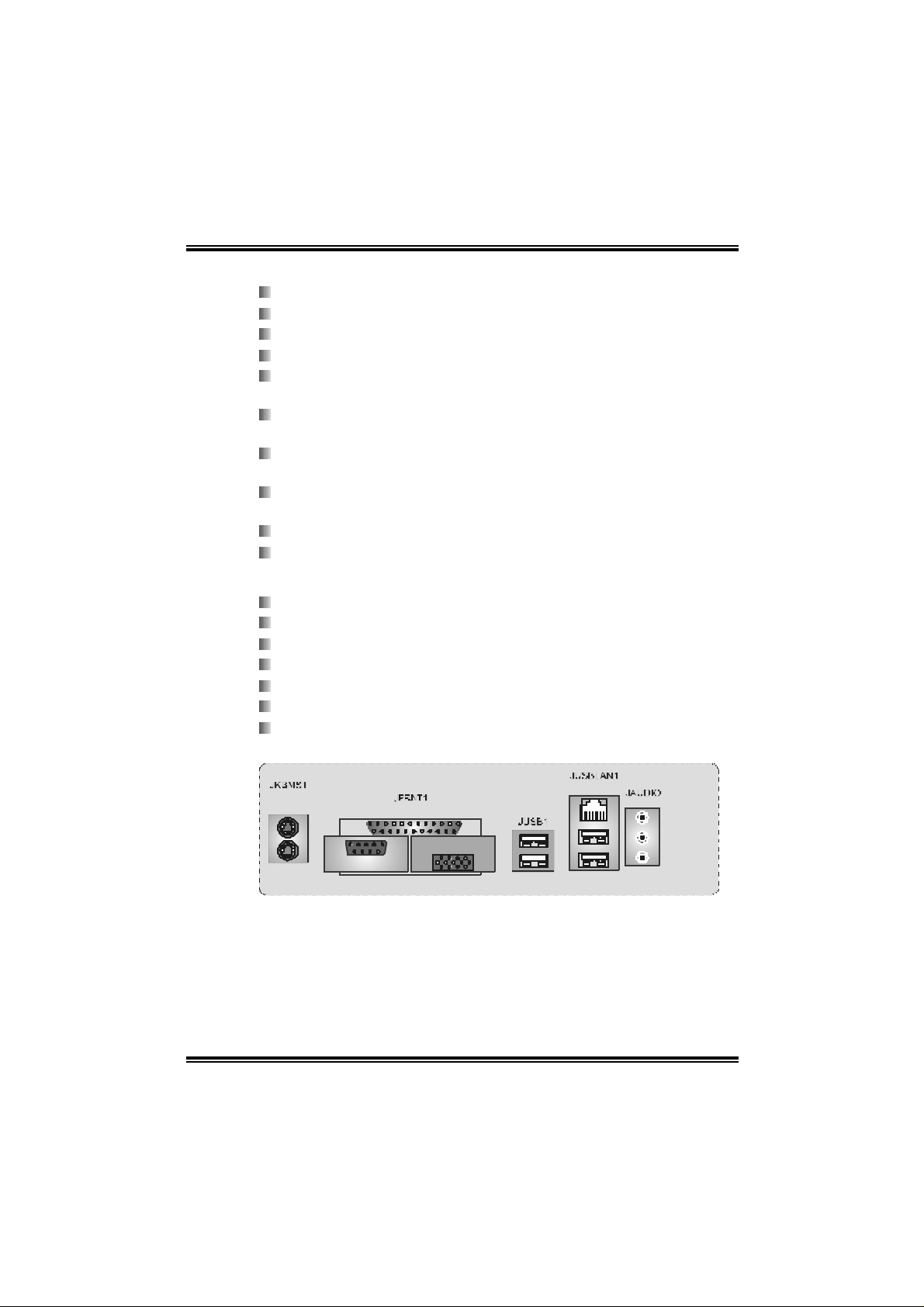
Rear Sid e Connect ors
4 USB 2.0 ports.
1 VGA port.
1 serial port.
1 pa r all el po r t.
1 R J- 45 LA N jac k .
1 PS/2 Mouse & Keyboard port.
1 vertical audio port including 1 line-in connector, 1 line-out
conn ec tor, and 1 MIC - i n co nn ect or.
PS/2
Mouse
PS/ 2
Keyboard
CO M1
JCOM1
Parallel
VGA 1
JVGA1
LAN
Line In/
Surround
Line Out
M i c In 1/
Base /Center
USB x2
USB x2
3
Page 6

I915G-M7
B. BIOS & Software
BIOS
Award legal BIOS.
Supports APM1.2.
Supports ACPI.
Supports USB Function.
Software
Sup por ts W ar ps peeder ™, 9t h T o uc h™, W IN F LASH ER ™ an d
FLASHER™.
Offers the hi ghest p e rformance for Windows 98 SE, Windows
2000, Windows M e, Windows XP, SCO UNIX etc.
1.2 PACKAGE CHECKLIST
FDD Cable * 1
HDD Cable * 1
User ’s Manu al * 1
Fu lly Se tup Dri ver CD * 1
Rear I/O Panel for ATX Ca se * 1
S/PDIF Cable * 1 (opti onal)
USB 2.0 Cable *1 (optional)
Serial ATA Cable * 1 (opti onal)
Serial ATA Power Switch Cable * 1 (optional)
4
Page 7

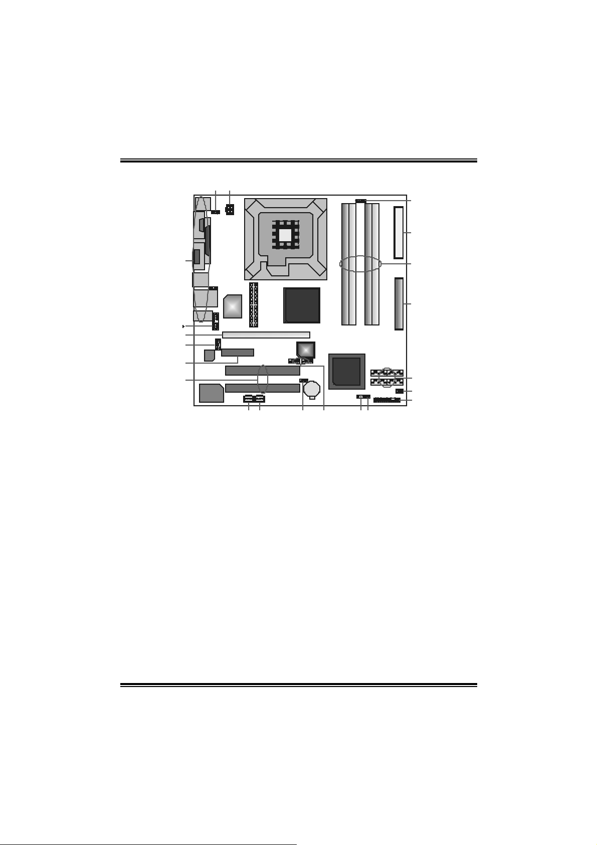
1.3 MOTHERBOARD LAYOU T
JKBMS1
JCOM1
JVGA1
JATX PWR2
JKBV1
1
JPRNT1
I915G-M7
LGA775
CPU1
JCFAN1
1
FDD1
DDRA1
DDRA2
DDRB1
DDRB2
JUSBV1
1
JRJ45USB1
JA UDIO1
Codec
LAN
12
13
JCDIN 1
1
JAUDIO2
14
JSPDIF_OUT1
(o ptiona l)
Super
JATXPWR1
I/O
24
PCI-EX1_ 1
Note: ● represents the 1st pin.
1
PCI- EX16
PCI1
PCI2
11
JSPDIF_IN1
(optional)
Intel 915G
BIO S
1
BAT1
IDE1
11
SATA3
ICH6
JCMOS1
SATA4
7
SATA2
JCL1
1
2
1
1
1777
1
1
JPANEL1
SATA1
JSFAN1
1
1
1
24
23
5
Page 8
I915G-M7
C
D
KLMNO
P
1.4 MOTHERBOARD COMPONENTS
LGA775
CPU1
W
V
E
B
Super
I/O
G
H
Codec
I
J
LAN
JATXPW R 1: ATX power source
A.
connector.
JU SBV1: power sourc e header for
B.
JU SB2 & JR J 45USB1.
JATXPW R 2: ATX power source
C.
connector.
JKBV1: power s ourc e header f or
D.
JKBMS1.
Rear s ide (back panel) connect ors.
E.
JAU DIO2: Front panel audio header.
F
PCI -EX16: PCI Ex press x 16 slot.
G.
JCDIN1: CD-ROM audio-in
H.
connector.
PCI -EX1_1: PCI-Express x 1 slot.
I.
PCI 1/ PCI2: Peripheral C omponent
J.
Int erc onnect lots .
JSPD IF_OU T1 (opt ional): Digital
K.
audio-out c onnector.
JSPD IF_IN1 (optional): Digit al
L.
audio-in connector.
U
A
In tel 915G
BI OS
ICH6
BAT1
T
S
1
R
Q
JU SBV3_1: power sourc e header for
M.
JUSB3/JUSB4.
JU SB3/JU SB4: f ront USB headers.
N.
JCM OS1: Clear CMOS header.
O.
JC L1: chassis open header.
P.
JPANEL1: fron t panel facilities header.
Q.
JSF AN 1: power header for system fan.
R.
SATA1~SATA4: on-board serial ATA
S.
connectors.
ID E1: Hard Dis k connector.
T.
DD RA 1 /DDRA2/DDRB 1/DDRB 2: DDR
U.
memory modules.
FDD1: Floppy D isk connect or.
V.
JCFAN1: pow er header for CPU fan .
W.
6
Page 9

I915G-M7
CHAPTER 2: HARDWARE INSTALLATION
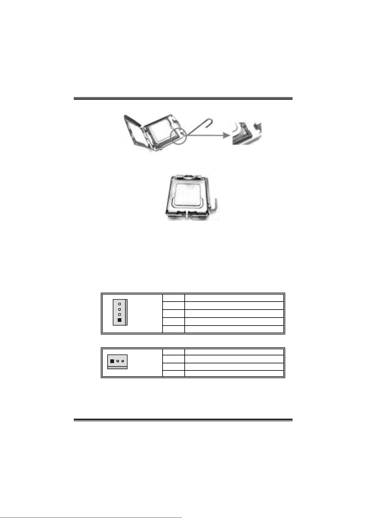
2.1 CENTRAL PROCESSING UNIT (CPU)
Spe cial Noti ce :
Remove Pin Cap before installation, and make good preservation for fu ture use.
When the CPU is removed, cover the Pin Cap on the empty socket to ensure pin
legs won ’t be damaged.
pin cap
Step 1: Pull the lever sideways away from the socket and then raise the
Step 2: Look for the black cut edge on socket, and the white dot on CPU
Step 2-1:
lever up to a 90-degree angle.
should point wards this black cut edge. The CPU will fit o nly in the
correct ori entation.
7
Page 10
I915G-M7
Step 2-2:
Step 3: Hold the CPU down firmly, and then cl ose the lever to com plete
the i nstal la ti on.
Step 4: Put the CPU Fan on the CPU and buckle it. Connect the CPU FAN
power cable to the JCFAN1. This completes the installation.
2.2 FAN HEAD ERS
These fan headers support cooling-fans built in the computer. T he fan
wir in g and plu g may be diff er ent accor ding to t he fan ma nuf ac tur er.
Connect the fan cable to the connector while m atching the black wire to
pin#1.
CPU FAN Header: JCFAN1
Pin Assignment
1 Ground
2 Power
1
JCFAN1
3 FAN RPM rat e sense
4 Smart Fan Control
System Fan Header: JSFA N1
Pin Assignment
1
JSFAN1
1 Ground
2 +12V
3 FAN RPM rate sense
Note:
The JCFAN1 and JSFAN1 support 4-pin and 3-pin head connector.
When connecting with wires onto connectors, please note that the red
wire is the positive and should be connected to pin#2, and the black
wire is Ground and should be connected to GND.
8
Page 11
I915G-M7
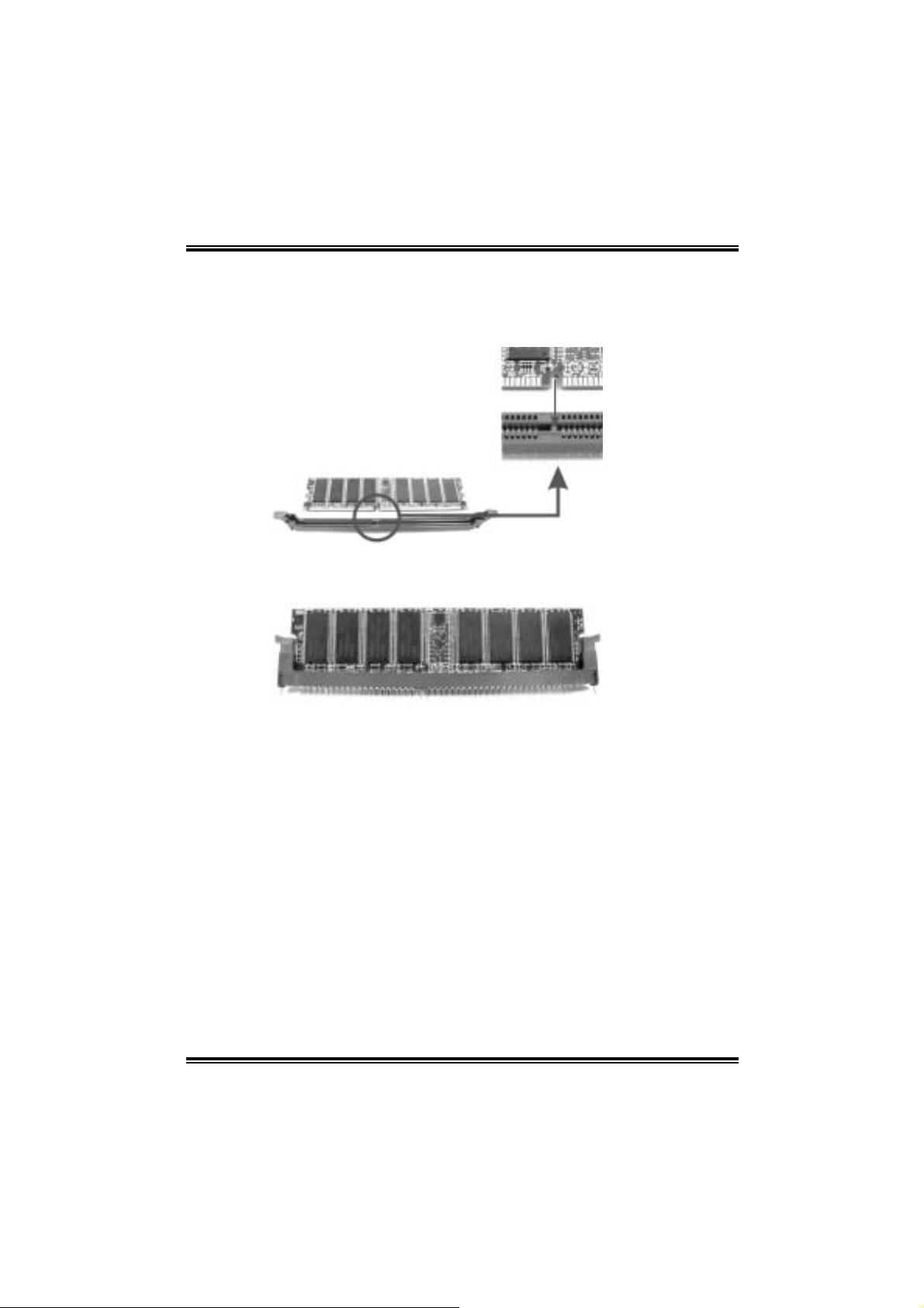
2.3 MEMORY MODUL E INSTALLATION
1. Unlock a DIMM sl ot by pressing the retaini ng clips outward. Align a
DIMM on the slot such that the notch on the DIMM matches the
break on the Slot.
2. Insert the DIMM vertically and firmly into the sl ot until the retaining
chip snap back in place and the DIM M is properly seated.
9
Page 12
I915G-M7
2.4 CONNECTO RS AND SLOTS
PCI1/PCI2: Peripheral Component Interconnect Slots
This motherboard is equipped with 5 standard PCI slots. PCI stands for
Peripheral Component Interconnect, and it is a bus standard for
expansi on cards. T his PCI slot is designated as 32 bits.
IDE1: Hard Disk Connectors
The motherboard has a 32-bit Enhanced PCI IDE Controller that
provides PIO Mode 0~5, Bus Master, and Ul tra DMA 33/ 66/ 100
func tionality. I t has two HDD co nnectors IDE 1 (primary ) and IDE2
(secondary).
The IDE connectors can connect a master and a slave dri ve, so you can
connect up to four hard disk drives. The fi rst hard drive should always be
connected to IDE1.
FDD1: Floppy Disk Connector
The motherboard provides a standard floppy disk connector that supports
360 K, 720K, 1.2M, 1.4 4 M and 2.8 8 M flo ppy d isk types. Th is conn ec tor
supports the provided floppy drive ri bbon cables.
SATA1~SATA4: Serial ATA Connectors
The motherboard has a PCI to SATA Controller with 2 channels SATA
interface, i t satisfies the SATA 1.0 spec and with transfer rate of 1.5Gb/s.
Pin Assignment Pin Assignment
17
SATA1~SATA4
1 Ground 2 TX+
3 TX- 4 Ground
5 RX- 6 RX+
7 Ground
10
Page 13
I915G-M7
CHAPTER 3: HEADERS & JUMPERS SETUP
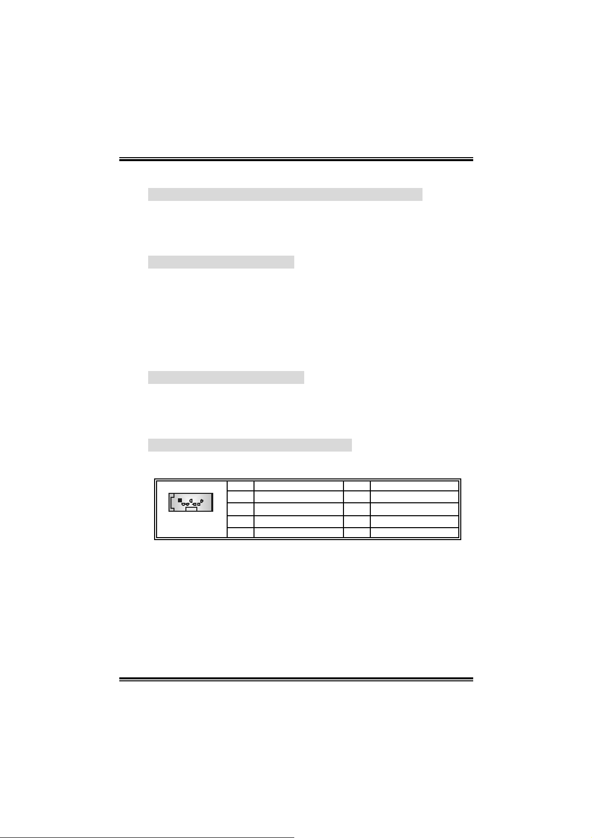
3.1 HOW TO SETUP JUMPE RS
The illustration shows how to set up jumpers. When the jum per cap is
placed on pins, the jumper is “close”, if not, that means the jumper is
“open”.
Pin opened Pin closed Pin1-2 closed
3.2 DETAIL SETTINGS
JKBV1/JUSBV1/JUSBV3_1:
Power Source He ade rs for USB ports
Assignment Description
JKBV1: +5V for JKBMS1.
1
Pin 1-2 close
Pin 2-3 close
1
+5V
+5V Standby
Voltage
JUSBV1: + 5V for JUSBLA N1 &
JUSB2.
JUSBV3_1: + 5V for JUSB3 /JUSB4.
JU SBV1: JKBMS1 and JUSB1 are
powered wit h +5V standby v olt age.
JU SBV2: JUSBLAN1 is powered by
+5V st andby voltage.
JU SBV3_4: JUSB2/3 are powered by
+5V st andby voltage.
Note:
In order to support this function “Power-on system via keyboard and
mouse ”, “JKBV1/JUSBV1/JUSBV3_1” jumper cap should be pla ced
on Pin 2-3.
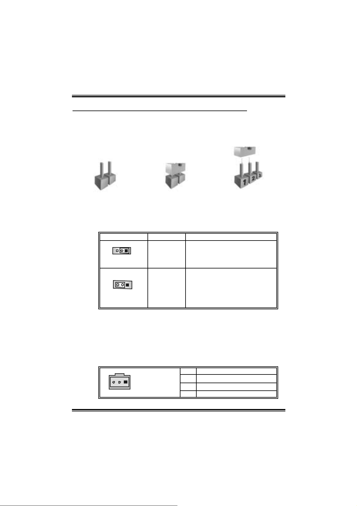
JSPDIF_OUT1 (optional): Di gital Au dio-out C onnector
This connector allows user to connect the PCI bracket SPDIF output
header.
Pin Assignment
1
JSPDIF_OUT1
1 +5V
2 SPDIF_OUT
3 Ground
11
Page 14
I915G-M7
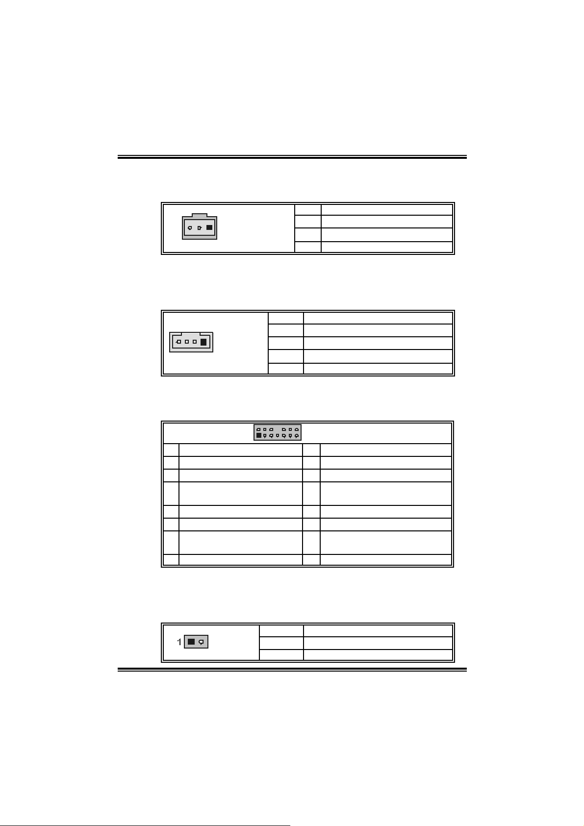
JSPDIF_IN1 (optional): Digital Audio-in Connector
This connector allows user to connect the PCI bracket SPDIF output
header.
Pin Assignment
1
JSPDIF_IN1
1 +5V
2 SPDIF_IN
3 Ground
JCDIN1: CD-R OM A ud io-i n Connector
This connector allows user to connect the audio source from the variety
devices, like CD-ROM, DVD-ROM, PCI sound card, PCI TV tu rner card
etc..
Pin Assignment
1 Left channel input
1
JCDIN1
2 Ground
3 Ground
4 Right channel input
JAUDIO2: Fr on t Panel Audio Header
This header allows user to connect the front audio out put cable wi th the
PC front panel. It will disa ble th e output on ba c k pan el audi o co nn ectors.
2
1
Pin Assignment Pin Assignment
1 Mic in/center 2 Ground
3 Mic power/Bass 4 Audio power
Right line out/ Speak er out
5
Right
7 Reserved 8 Key
9 Left line out/ Speak er out Lef t 10 Left line out/Speak er out Left
Right line in/R ear speaker
11
Right
13 Left line in/Rear speak er Lef t 14 Left line in/Rear speak er Left
14
13
JAUDIO2
6 Right line out/ Speak er out Right
12 Right line in/R ear speaker Right
JCL1: Chassis Open Header
T his connecto r allows sy stem to monito r P C case open status. If the
signal has been triggered, i t will record to the CMOS and show the
message on next boot-up.
Pin Assignment
JCL1
1 Cas e open signal
2 Ground
12
Page 15
I915G-M7
JUSB3/JUSB4: Front USB Heade rs
This motherboard provides 2 USB 2.0 headers, which all ows user to
connect additional USB cable on the PC front panel, and also can be
connected with internal USB devices, like USB card reader.
Pin Assignment Pin Assignment
210
1
JUSB3/JUSB4
1 +5V (f used) 2 +5V (f used)
3 USB- 4 USB5 USB+ 6 USB+
7 Ground 8 Ground
9 Key 10 NC
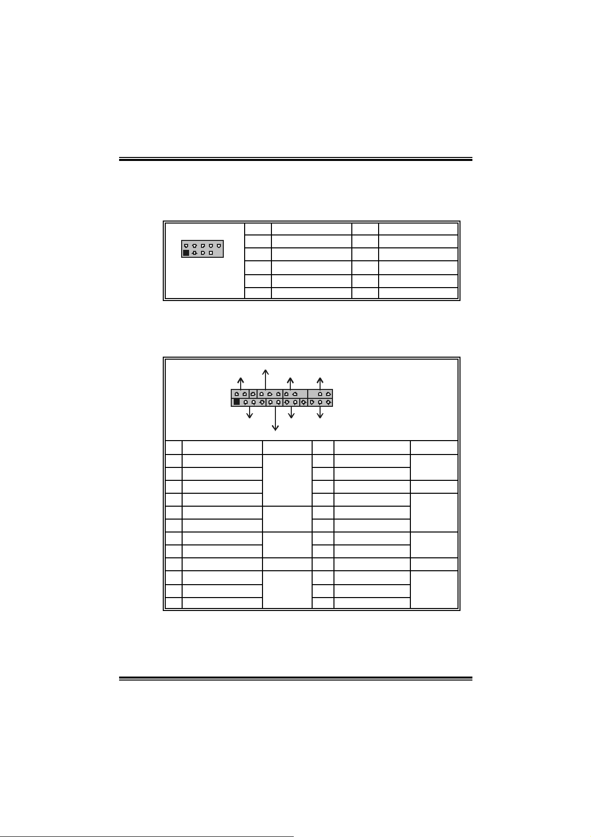
JPANEL1: Front Panel Heade r
This 24-pin connector includes Power-on, Reset, HDD LED, Power LED,
Sleep button, speaker and IrDA Connection. It allows user to connect
the PC case’s front panel switch functions.
PWR_LED
SLP
2
1
SPK
Pin Assignment Function Pin Assignment Function
1 +5V 2 Sleep control
3 N/A 4 Ground
5 N/A 6 N/A N/A
7 Speaker
9 HDD LED (+) 10 Power LED (+)
11 HEE LED (-)
13 Ground 14 Power button
15 Reset control
17 N/A 18 Key
19 N/A 20 Key
21 +5V 22 Ground
23 IRTX
On/Off
++
+--
RST
HLED
Speaker
Connector
Hard driv e
LED
Reset
button
IrDA
Connector
IR
24
23
IR
JPANEL1
8 Power LED (+)
12 Power LED (-)
16 Ground
24 IRRX
Sleep
button
Power LED
Power-on
button
IrDA
Connector
13
Page 16
I915G-M7
JCMOS 1 : Clea r CMOS H eader
By placing the jumper on pin2-3, it allows user to restore the BIOS safe
setting and the CMOS data, please carefull y follow the procedures to
avo id da ma ging th e mot her b oar d.
JCMOS1 Assignment
Pin 1-2 close
Pin 2-3 close
Norm al Operation (D ef ault).
Clear CMOS data.
※ Clear CMOS Procedures:
1. Remove AC power line.
2. Set the jumper to “Pin 2-3 cl ose”.
3. Wait for five seconds.
4. Set the jumper to “Pin 1-2 cl ose”.
5. Power on the AC.
6. Reset your desired password or clear the CM OS data.
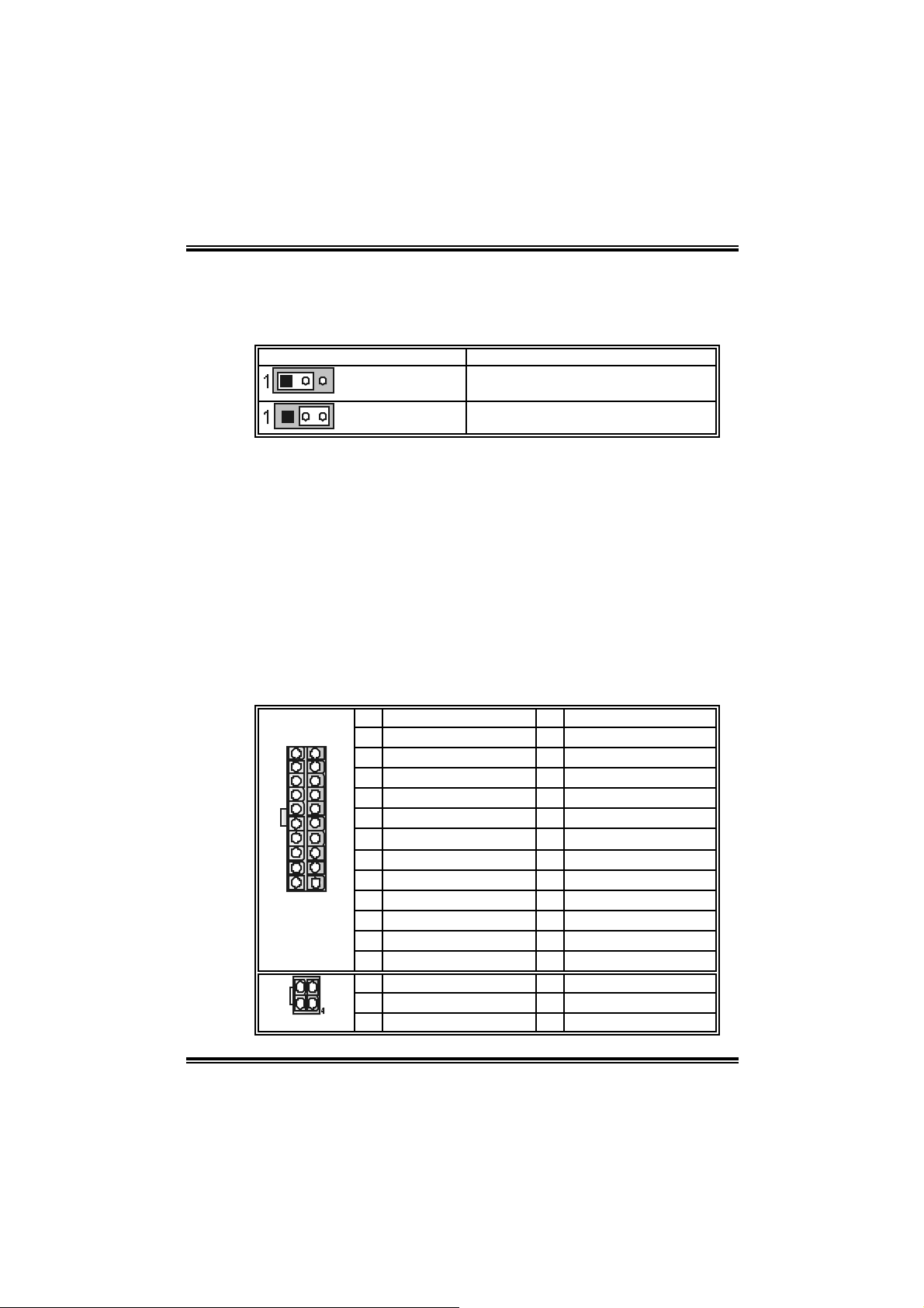
JATXPW R1/PATXPW R2: Power C onnectors
JATXPWR1: This connector allows user to connect with 20-pin power
conn ec tor on t h e ATX pow er s upp ly.
JATXPWR2: By connecting this connector, it will pro vi de +12V to CPU
power ci rcuit.
Pin Assignment Pin Assignment
13
24
JATXPWR1
1
2
JATXPWR2
1 +3.3V 13 +3.3V
1
2 +3.3V 14 -12V
3 Ground 15 Ground
4 +5V 16 PS_ON
5 Ground 17 Ground
6 +5V 18 Ground
7 Ground 19 Ground
8 PW_OK 20 -5V
12
9 Standby Voltage +5V 21 +5V
10 +12V 22 +5V
11 +12V 23 +5V
12 2 x 12 D etect 24 Ground
3
Pin Assignment Pin Assignment
1 +12V 3 Ground
2 +12v 4 Ground
14
Page 17

I915G-M7
15
Page 18
I915G-M7
CHAPTER 4: USEFUL HELP
4.1 AWARD BIOS BEEP CODE
Beep Sound Meanin g
One long beep f ollowed by t wo s hort
beeps
High-low siren sound CPU overheated
One Short beep when system boot-up N o error found during POST
Long beeps every ot her second No DRAM detected or inst all
4.2 EXTRA INF ORMA TION
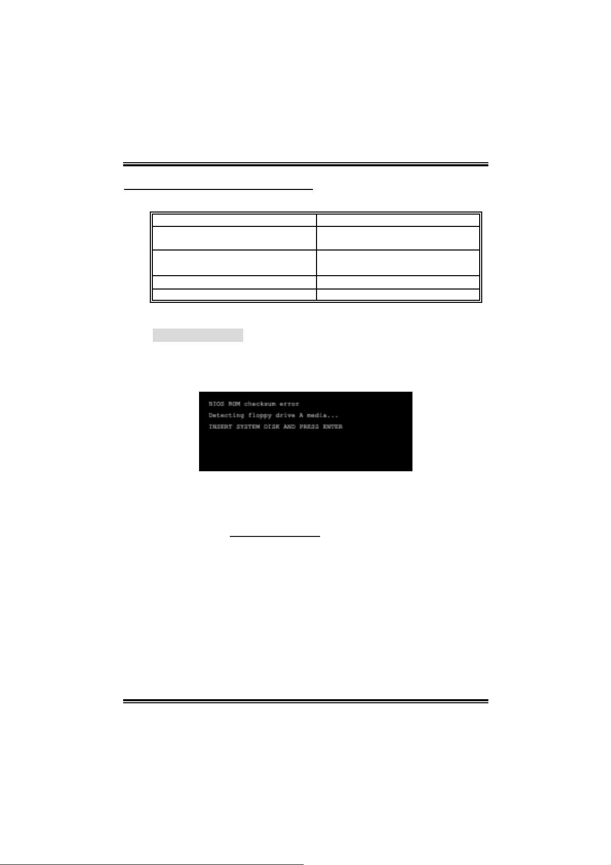
A. BIOS Update
After you fail to up d ate B IOS or BIOS is inva ded by virus, the
Boot-Block function will help to restore BIOS. If the following message
is shown after boot-up the system, it means the BIOS contents are
corrupted.
Video card not f ound or video card
mem ory bad
Sys t em will shut down automat ically
In this Case, please follow the procedure below to restore the BIOS:
1. Mak e a bootab le fl op py d isk .
2. Download the Flash Uti lity “AWDFLASH.exe” from the Biostar
websi te: www.biostar.com.tw
3. Confi rm m otherboard model and download the respectively BIOS
fr om Bi os t ar w ebsit e.
4. Copy “AWDFLASH.exe” and respectively BIOS into floppy di sk.
5. Insert the bootable disk into floppy drive and press Enter.
6. System will boo-u p to DOS prompt.
7. Type “Awdflash xxxx.bf/sn/p y/ r” i n DOS prompt.
8. System will update BIOS automatically and re sta rt.
9. The BIOS h as b ee n recovered a nd will work prope rly.
16
Page 19

I915G-M7
B. CPU Overheated
If the system shutdown automati cally after power on system for
seconds, that means the CPU protecti on function has been activated.
When the CPU is over heated, the motherboard will shutdown
automatically to avoid a damage of the CPU, and the system may not
power on again.
In this case, please double check:
1. The CPU cooler surface is placed evenly with the CPU surface.
2. CPU fan is rotated normally.
3. CPU fan speed is fulfilling with the CPU speed.
After confirmed, please follow steps below to relief the CPU protection
function.
1. Remove the power cord from power supply for seconds.
2. Wai t for seconds.
3. Plug in the power cord and boot up the system.
Or you can:
1. Clear the CMOS data.
(See “Close CMOS Header: JCM OS1” section)
2. Wai t for seconds.
3. Power on the sy st em again.
17
Page 20

4.3 TROUBLESHOOTIN G
e
Probable Solution
1. No power to the system at all
Power light don’t illuminat e, fan
inside power s upply does not turn
on.
2. Indic at or light on k ey board does
not t urn on.
Sys t em inoperat iv e. Keyboard lights
are on, power indic at or lights are lit,
and hard driv e is spinning.
Sys t em does not boot from hard disk
drive, can be booted from optic al drive.
Sys t em only boots from opt ic al drive.
Hard disk can be read and applications
can be used but booting from hard dis k
is imposs ible.
Screen m essage say s “Invalid
Conf igurat ion” or “CMOS Failure.”
Cannot boot sys t em aft er inst alling
sec ond hard drive.
I915G-M7
1. Make sure power cable is
sec urely plugged in.
2. Replace cable.
3. Contact techni cal support .
Us ing even pres s ure on bot h ends of
the DIMM, press down firm ly until the
module s naps int o place.
1. Chec k cable running f rom disk to
disk controller board. Make sure
both ends are s ec urely plugged
i n; c heck t h e dr iv e type in the
standard CMOS se tup.
2. Back ing up the hard driv e is
ext rem ely im port ant. All hard
disk s are c apable of breaking
down at any t ime.
1. Back up data and applic at ions
files.
2. Ref orm at the hard drive.
Re-ins t all applicat ions and data
using backup disks.
Rev iew sys t em’s equipment. Make s ur
correc t inf orm at ion is in setup.
1. Set m aster/slave jumpers
correctly.
2. Run SETUP program and select
correc t driv e types. Call t he drive
manufac turers for compatibili t y
with other drives.
18
Page 21

I915G-M7
CHAPTER 5: WARPSPEEDER™
5.1 INTRODUCTION
[WarpSpeeder™], a new powerful control utility, features three
user-friendly functions including Overclock Manager, Overvol tage
Manager, and Hardware Monitor.
With the Overclock Manager, users can easily adjust the frequency they
prefer or they can get the best CPU performance with just one click. T he
Overvol tage Manager, on the other hand, helps to power up CPU core
vol tage an d Me mor y v olt a ge. The co o l H ar dw are Monit or smartly in d icates
the temperatures, voltage and CPU fan speed as well as the chipset
information. Also, in the About panel, you can get detail descriptions about
BIOS model and chipsets. In addition, the frequency status of CPU,
memory, AGP and PCI along with the CPU speed are synchronically
s how n on our ma i n pan el .
Moreover, to protect users' computer systems i f the setting is not
appropriate when testing and results in system fai l or hang,
[WarpSpeeder™] technology assures the system stability by automatically
rebooting the computer and then restart to a speed that is either the
original system speed or a suitable one.
5.2 SYSTEM REQUIREMENT
OS Support: Windows 98 SE, Windows M e, Windows 2000, Windows XP
DirectX: DirectX 8.1 or above. (The Windows XP operating system
incl udes DirectX 8.1. If you use Windows XP, you do not need to install
Dir ec tX 8.1.)
19
Page 22

I915G-M7
5.3 INSTALLATION
1. Execute the setup execution file, and then the following dialog will pop
up. Please click “Next” button and foll ow the default procedure to
install.
2. When you see the following dialog in setup procedure, it means setup
is completed. If the “Launch the WarpSpeeder Tray Utility” checkbox
is c hec ked, the Tray Icon u tility an d [WarpSpeed er™] utility will be
automatically and immediately launched after you click “Finish”
button.
Usage:
The following figures are just only for reference, the screen pri nted in
thi s user ma nual will chan ge acc ording t o yo ur moth erboa rd on ha nd.
20
Page 23

I915G-M7
5.4 [WARPSPEEDER™] INC LUDES 1 TRAY IC ON AND 5 PANELS
1. Tray Icon:
Whenever the Tray Icon utility i s launched, i t will displa y a little tray
icon on the right side of Windows Taskbar.
This utility is responsi ble for conveniently invoking [WarpSpeeder™]
Utility. You can use the mouse by cli cki ng the left button in order to
invoke [WarpSpeeder™] directl y from the little tray icon or you can
right-click the little tray icon to pop up a popup menu as following
figure. The “Launch Utility” item in the popup menu has the same
func tion as mouse left -click on t ray icon an d “Exit” item will clo se
T ray Icon utility if sel e cted.
21
Page 24

I915G-M7
2. Main Panel
If y ou click the tray icon, [WarpSpe ed er™] utility will be invoked.
Please refer to the following figure; the utility’s first wi ndow you will
see is Main Panel.
Main Panel con tains fe atures as foll ows:
a. Display th e C PU Speed, CPU ex terna l clock, Memory clock, AGP cl ock,
and PCI clock information.
b. Contains About, Voltage, Overclock, and Hardware Monitor Buttons for
invoking respecti ve panels.
c. With a user - fr ie nd ly Status An im at io n, it c an represent 3 over cl ock
percentage stages:
Man walking→overcl ock percentage from 100% ~ 110 %
Panther running→overclock percentage from 110% ~ 120%
Ca r racing →overclock percentage from 120% ~ above
22
Page 25

I915G-M7
3. Voltage Pa nel
Cli c k the Vol tage button in Main Pa nel , th e button will b e highlighted
and the Volta ge Pa nel will sl ide out t o up as the following fig ure.
In this panel, you can decide to increase CPU core vol tage and
Memory voltag e or not. Th e default setting is “No”. If yo u want to get
the best performance of overclocking, we recommend you click the
opti on “Yes”.
23
Page 26

I915G-M7
4. Over clock Panel
Cli c k the Overclock button in Ma in Panel, the button will be
highlighted and the Overclock Panel wi ll slide out to left as the
fol l owi ng f igur e.
Overclock Panel contains the these feature s:
a. “–3MHz button”, “-1MHz button”, “+1M Hz button”, and “+3MHz button”:
provide user the abili ty to do real-time overclock adjustment.
Warning:
Manually overclock is pot entially dangerous, especially when the
overclocking percentage is ov er 110 %. We strongly recommend you
verify every s peed you ov erc lock by c lick t he Verif y button. Or, you can
just click Aut o overclock but t on and let [WarpSpeeder™] automatically
gets the best result for you.
b. “Recovery Dialog button”: Pop up the foll owi ng dialog. Let user select
a restoring way if system need to do a fail-safe reboot.
24
Page 27

I915G-M7
c. “Auto-overclock button”: User can click this button and
[Wa rpS peeder™ ] will set the best and stable perf ormance and
frequency automatically. [WarpSpeeder™] utili ty will execute a
se rie s of te stin g until sy stem fail. Then system will do fail-safe
reboot by using Watchdog function. After reboot, the
[WarpSpeeder™] utility will restore to the hardware defaul t
setting or load the verified best and stabl e frequency according
to the Recovery Dialog ’s setting.
d. “Verify button”: User can click this button and [WarpSpeeder™]
will proceed a testing for current frequency. If the testing is ok,
then the current fre q uency will be saved into system registry. If
the testing fai l, system will do a fail-safe rebooti ng. After reboot,
the [WarpSpe ed er™] uti lity will restore to the hardware def au lt
setting or load the verified best and stabl e frequency according
to the Recovery Dialog ’s setting.
Note:
Becaus e the t esting programs, invok ed in Auto-overclock and Verify,
include D irectDraw, D irect3D and DirectShow t ests, the DirectX 8.1 or
newer runtime library is required. And pleas e make sure y our dis play
card’s color depth is High color (16 bit ) or True c olor( 24/32 bit ) that is
required for Direc t3D rendering.
5. Hardware Monitor Panel
Cli c k the Hardware Moni to r bu tton in Main Pane l, th e button will be
highlighted and the Hardware Monitor panel will sl ide out to left as
the fo l lowing f ig ur e.
In this panel, you can get the real-time status information of your
system . The info rmation will be re fre shed every 1 second.
25
Page 28

I915G-M7
6. About Panel
Click the “about” button in M ain Panel, the button will be highlighted
and t h e Ab out Pa ne l will s l id e out t o up as the following f ig ur e.
In this panel, you can get model name and detail information in hints
of all the chipset that are related to overclocking. You can also get
the mainboard’s BIOS model and the Version number of
[WarpSpeeder™] utility.
26
Page 29

I915G-M7
Note :
Because the overclock, overvoltage, and hardware monitor features
are controlled by several separate chipset, [WarpSpeeder™] divide
these features to separate panels. If one chipset is not on board, the
corr elative but ton in Main panel wil l be disa bled, bu t will not i nterf ere
other panels’ functions. This property can make [WarpSpeeder™]
utility more robus t.
11/17, 04
27
Page 30

I915G-M7 BIOS Setup
BIOS Setup..................................................................................................... 1
1. M ain M enu................................................................................................4
2. Standard CM OS Features .................................................................... 7
3. Advanced BIOS Features ..................................................................... 9
4. Advanced Chipset Features ..............................................................16
5. Integrated Peripherals ........................................................................20
6. Po wer Managem ent Setup.................................................................27
7. PnP/PCI Configurations .....................................................................33
8. PC Health Status ..................................................................................36
9. Frequency Control...............................................................................38
i
Page 31

BIOS SETUP
Intro duction
This manual discussed Award™ Setup program built into the ROM BIOS. The
Setup program allows users to modify the bas ic system configuration. This special
information is then stored in b attery-backed RAM so that it retains the Setup
information when the power is turned off.
The Award BIOS™ ins talled in your computer system’s ROM (Read Only Memory)
is a custom version of an industry stand ard BIOS. This means that it supports Intel
Pentium
support for standard devices such as disk drives and serial and paralle l ports.
Adding important has cus to mized the Award BIOS™, but nonstandard, features
such as virus and password protection as well as special support for detailed
fine-tuning of the c hipset contro lling the entire system.
The rest of this manual is intended to guide you through the process of configuring
your system using Setup.
Plug and Play Support
These AWARD BIOS supports the Plug and Play Version 1.0A specification. ESCD
(Extended System Configuration Data) write is supported.
EP A Green PC Support
This AWARD BIOS s upports Vers ion 1.03 of the EPA Green PC specification.
APM Support
These AWARD BIOS supports Version 1.1 &1.2 of the Advanced Power
Management (APM) sp ecific ation. Po wer management features ar e implement ed
via the System Management Interrupt (SMI). Sleep and Susp end power
management modes are supported. This AWARD BIOS can manage power to the
hard disk drives and video monitors.
®
4 processor input/output system. The BIOS provides critical low-level
I915G-M7 BIOS Setup
1
Page 32

ACPI Support
Award ACPI BIOS support Version 1.0 of Advanced Co nfiguration and Power
interface specification (ACPI). It provides ASL code for power management and
devic e configuration cap abilities as defined in the ACPI specification, developed
by Mic rosoft, Intel and Toshiba.
PCI Bus Support
This AWARD BIOS also supports Vers ion 2.1 of the Intel P CI (Peripheral
Component Interconnect) local b us specificatio n.
DRAM S uppo rt
DDR DRAM (Double Data Rate Synchronous DRAM) are supported.
Supported CPUs
This AWARD BIOS supports the Intel Pentium ® 4 CPU.
I915G-M7 BIOS Setup
2
Page 33

I915G-M7 BIOS Setup
Using Setup
In ge neral, you use the ar row keys to h ighlight items, p ress:
<Enter> to select,
<PgUp> and <PgDn> to change entries,
<F1> for help,
<Esc> to quit.
The following table provides more detail about how to navigate in the Setup
pro gram b y using the keyboard.
Keystroke Function
Up arrow Move to previous item
Down arrow Move to next item
Left arrow Move to the item on the left (menu bar)
Right arrow Move to the item on the right (menu bar)
Move Enter Move to the item you desired
PgUp key Increase the numeric value or make changes
PgDn key Decrease the numeric value or make changes
+ Key Increase the numeric value or make changes
- Key Decrease the numeric value or make changes
Esc key Main Menu – Quit and not save changes into CMOS
Status Page Setup Menu and Option Page Setup Menu – Exit
Current page and return to Main Menu
F1 key General help on Setup navigation keys
F5 key Load previous values from CMOS
F7 key Load the optimized defaults
F10 key Save all the CMOS changes and exit
3
Page 34

I915G-M7 BIOS Setup
1. MAIN MENU
Once you enter Award BIOS™ CMOS Setup Utility, the Main Menu will appear on the
screen. The Main Menu allows you to s elec t fro m s everal setup funct ions. Use the arrow
keys to select among the items and press <Enter> to accept and enter the sub-menu.
0
WARNIN G
The information about BIOS defaults on this manual (Figure 1,2,3,4,5,6,7,8,9) is just only
for reference; please refer to the BIOS installed on board, for upd ate information.
1.1 STANDARD CM OS FEATURES
This submenu co ntains ind ustry sta ndard configurable options .
1.2 ADVANCED BIOS FEATURES
This sub menu allo ws you to configur e enhanced featur es of the BIOS.
1.3 ADVANCED CHIPSET FEATURES
This submenu allows you to configure spec ial chipset features.
1.4 INTEGRATED PERIPHERALS
This submenu allows you to configure certain IDE hard drive options and
Programmed Input/ Output features.
4
Page 35

I915G-M7 BIOS Setup
1.5 POWER MANAGEMENT SETUP
This submenu allows you to configure the power management features.
1.6 PNP/PCI CONFIGURATIONS
This submenu allows you to configure certain “Plug and Play” and PCI options.
1.7 PC HEALTH STATUS
This submenu allows you to mo nitor the hard ware of your system.
1.8 FRE QUENCY CONTROL
This sub menu allo ws you to change CPU Vcore Voltage and CP U/PCI clock.
(However, this function is strongly recommended not to use. Not properly
change the voltage and clock may cause CPU or M/B damage!)
1.9 LOAD OPTIMIZ ED DEFAULTS
This selection allo ws you to reload the BIOS when the system is having problems
particularly with the boot sequence. These configurations are factory settings
optimized for this system. A confirmation message will be displayed before defaults
are set.
1.10 SET SUPER VI SOR PASSWORD
Setting the supervisor password will prohib it everyone except the supervisor from
making changes using the CMOS Setup Utility. You will be prompted with to enter
a password.
5
Page 36

I915G-M7 BIOS Setup
1.11 SET USER PASSWORD
If the Supervisor Pass word is not set, then the User Password will f unction in the
same way as the Supervisor Password. If the Supervisor Password is set and the
User Pass word is set, the “ User” will only be able to view configurations but will not
be able to change them.
1.12 SAVE & EXIT SETUP
Save all configuration c hanges to C MOS(memo ry) and exit s etup. Confir mation
message will be displayed before proceeding.
1.13 EXIT WITHOUT SAVING
Abandon all changes made during the c urrent session and exit setup. Co nfirmation
message will be displayed before proceeding.
1.14 UPGRADE BI OS
This sub menu allows you to upgrade bios.
6
Page 37

I915G-M7 BIOS Setup
2. STANDARD CMOS FEATURES
The items in Standard CMOS Setup Menu are divided into 10 categories. Each category
includes no, one or more than one setup items. Use the arrow keys to highlight the item and
the n us e the<P gUp> or <PgDn> keys to select the value you want in each item.
7
Page 38

I915G-M7 BIOS Setup
2.1 MAIN MENU SELE CTIONS
This table sho ws t he selections that you can make on the Main Menu.
Item
Date mm : dd : yy
Time hh : mm : ss Set the system internal clock.
IDE Primary
Master
IDE Primary Slave
IDE Secondary
Master
IDE Secondary
Slave
Drive A
Drive B
Video
Halt On
Base Mem ory N/A
Options Description
Set the system date. Note that the ‘Day’
automatically changes when you set the
date.
Op tions are in its
sub menu.
Op tions are in its
sub menu.
Op tions are in its
sub menu.
Op tions are in its
sub menu.
360K, 5.25 in
1.2M, 5.25 in
720K, 3.5 in
1.44M, 3.5 in
2.88M, 3.5 in
None
EGA/VGA
CGA 40
CGA 80
MONO
All Errors
No Errors
All, but Keyboard
All, but Diskette
All, but Disk/ Key
Press <Enter> to enter the sub menu of
detailed options
Press <Enter> to enter the sub menu of
detailed options.
Press <Enter> to enter the sub menu of
detailed options.
Press <Enter> to enter the sub menu of
detailed options.
Select the type of floppy disk drive
insta lled in your system.
Select the default video device.
Select the situation in which you want the
BIOS to stop the POST process and
notify you.
Disp lays the amount of conventional
memory detected during boot up.
Extended Memory N/A
Total Memory N/A
Disp lays the amount of extended memory
detected during boot up.
Disp lay s the to tal memory availa ble in
the system.
8
Page 39

I915G-M7 BIOS Setup
3. AD VANCED BIOS FEATURES
3.1 CPU FEATUR E
3.1.1 Delay Prior to Thermal
Set this item to enable the CPU T hermal functio n to engage after the specified
time.
The Choices : 4, 8, 16 (default), 32.
9
Page 40

I915G-M7 BIOS Setup
3.1.2 Thermal Management
Allow you to choose the thermal management method of your monitor.
The Choices : Therma l Monitor 1 (default), Thermal Monitor2.
Notes: The choices will be different according to your CPU features.
3.1.3 TM2 Bus Ratio
Represents the frequency. Bus ratio of the thro ttled performance st ate that will be
initiated when the on-die sensor goes from no t hot to hot.
The Choices: 0X (default).
3.1.4 TM2 Bus VID
Represents the voltage of the throttled performance state that will b e initiated
when the on-die sensor goes from not hot to hot.
The Choices: 0.8375 (default).
3.1.5 Limit CPU I D Max Val
Set limit CPU ID maximum vale to 3, it s hould be disabled for Win XP.
The Choices: Disabled (default), Enabled.
3.1.6 Execute Disable Bit
The Choices : Enabled(d efault) , Disabled.
10
Page 41

I915G-M7 BIOS Setup
3.2 HARD DISK BOOT PRIORITY
These BIOS attempt to load the operating system from the device in the sequence selected in
these items.
The Choices: P ri. Master, Pri.Slave, Sec.Master, Sec. Slave, USBHDD0, USBHDD1,
USBHDD2 and Bootable Add- in Ca rde .
11
Page 42

I915G-M7 BIOS Setup
3.3 BOOT SEQ & FLOPPY SETUP
3.3.1 First/Second/ Third/Boot Other Device
Thes e BIOS att empt to load the operating system from t he device in the
sequence selected in these items.
The Choices: Floppy, LS120, HDD-0, SCSI, CDROM, HDD-1, HDD-2,
HDD-3, ZIP100, LAN, HPT370, Disabled, Enabled.
3.3.2 Swap Floppy Dri ve
For systems with two floppy drives, this option allows you to swap lo gical drive
assignments.
The Choices: Disabled (default), Enabled.
3.3.3 Boot Up Floppy S eek
Enabling this option will test the floppy drives to determine if they have 40 or 80
tracks. Disabling this option reduc es the time it takes to boot-up.
The Choices : Dis ab led, Enabled (default).
3.3.4 Report NO FDD for Win95
The Choices : NO (default).
12
Page 43

I915G-M7 BIOS Setup
3.4 VIRUS WARNING
This option allows yo u to choos e the Virus Warning feature that is us ed to pro tect the
IDE Hard Disk boot sector. If this function is enabled and an attempt is made to write
to the boot sec tor, BIOS will display a warning message on the screen and sound an
alarm beep.
Enab led Virus protect ion is activated.
Disabled (default) Virus protection is disabled.
3.5 CPU L3 CACHE
Depend ing on the CPU/chipset in use, you may be able to increase memory
access time with this option.
Ena ble d (default) Enable cache.
Disabled Disable cache.
3.6 HYPER-THREADI NG TECHNOL OGY
This option allows you to enable or disabled CPU Hyper-Threading. Enabled for
Windows XP and Linux 2.4.x (OS optimized for Hyp er Threading Technology.
Disab led for other OS (OS not optimized for Hyper T hreading Technology.
The Choices : Enabled (Default), Disabled.
3.7 QUICK POWER ON SELF TEST
Enab ling this option will cause an abridged version of the Power On S elf-Test (POST )
to execute after yo u power up t he co mputer.
Dis ab led No rmal P OST.
Ena ble d (default) Enable quick POST.
3.8 BOOT UP NUM LOCK STATUS
Selects the NumLock. State after power on.
On (default) Numpad is number keys.
Off Nump ad is arrow keys.
3.9 GATE A20 OPTION
Select if chipset or keyboard co ntroller should contro l Gate A20.
No rmal A pin in the keyboard co ntro ller controls G ate A20.
Fast (default) Lets chipset contro l Gat e A20.
13
Page 44

I915G-M7 BIOS Setup
3.10 TYPEMATIC RATE SETTING
When a key is held down, the keystroke will repeat at a rate determined by the
keyboard controller. When enabled, the typematic rate and typematic delay can be
configured.
The Choices: Disabled (default), Enabled.
3.11 TYPEMATIC RATE (CHARS/SEC)
Sets the rate at which a keystroke is repeated when yo u hold the key down.
The Choices : 6 (default), 8,10, 12, 15,20, 24,30.
3.12 TYPEMATIC DELAY (MSEC)
Sets the delay time after the key is held down before it begins to repeat the keystroke.
The Choices : 250 (d e fault ), 500, 750, and 1000.
3.13 SECURITY OPTION
This option will enable only ind ividuals with passwo rds to bring the system online
and/or to use the CMOS Setup Utility.
System A password is required for the system to boot and is also
required to access t he Setup Utilit y.
Setup (default) A pass word is required to acc ess the Set up Utility o nly.
This will only app ly if passwords are set fro m the Setup main menu.
3.14 APIC MODE
Selecting Enabled enables APIC device mode reporting from the BIOS to the
operating system.
The Choices : Enabled (default), Disabled.
3.15 MPS VERSION CONTROL FOR OS
The BIOS supports versio n 1.1 and 1.4 of the Intel multip rocessor specification.
Selec t versio n supported b y the operatio n sys tem running on t his comp uter.
The Choices : 1.4 (default), 1.1.
14
Page 45

I915G-M7 BIOS Setup
3.16 OS SELECT FOR DRAM > 64MB
A choice other than Non-OS2 is only used for OS2 s ystems with memory exceeding
64MB.
The Choices : No n-O S2 (default), OS2.
3.17 SMALL LOGO (EPA) SHOW
This item allows you to s elect whether the “Smal l Logo” shows.
Ena ble d (default) “Small Logo” shows when system boots up.
Disabled No “Small Logo” shows when system boots up.
3.18 SUMMARY SCREEN SHOW
This item allows you to enable/d isable the summary sc reen. Summary screen
means system configuration and PCI device listing.
The cho ices: Enab led, Disabled (default).
15
Page 46

I915G-M7 BIOS Setup
4. ADVANCED CHIPSET FEATURES
This submenu allows you to configure the specific features o f the chipset installed o n your
system. This chipset manage bus speeds and access to system memory resources, such as
DR AM. It also coo rdinates communications with the PCI bus. The default settings that
came with your system have been optimized and therefore should not be changed unless you
are s usp icious that the settings have been changed inco rrectly.
4.1 DRAM TIMING SELECTABLE
When synchronous DRAM is installed, the number of clock cycles of CAS latency
depends on the DRAM timing.
The Cho ices: By SPD (default), Manual.
4.2 CAS LATENCY TIME
When synchronous DRAM is installed, the number of clock cycles of CAS latency
depends on the DRAM timing.
The Choices : Au to (default).
16
Page 47

I915G-M7 BIOS Setup
4.3 DRAM RAS# TO CAS# DELA Y
This field let you insert a timing delay between the CAS and RAS strobe signals,
used when DRAM is written to, read from, or refreshed. Fast gives faster
performance; and slow gives more stable performance. This field applies only when
sync hrono us D RAM is ins t alled in th e syst em.
The Choices : Au to(d efault).
4.4 DRAM RAS# PRECH ARGE
If an ins ufficient number of cycles is allowed for RAS to accumulate its charge
before DRAM refresh, the refresh may be incomplete, and the DRAM may fail to
retain data. Fast gives faster performance; and Slow gives more stable performance.
This field applies only when s ynchronous DR AM is installed in the system.
The Choices : Au to(d efault).
4.5 PRECHARGE DELAY (TRAS)
This item controls the number o f DRAM cloc ks to ac tivate the p recharge delay.
The Choices : Au to (default).
4.6 SYSTEM MEMORY FREQUENCY
This item allows you to select the Memory F requenc y.
The Choices : Au to (default), DDR266, DDR300, and DDR400.
4.7 SLP_S4# ASSERTION WIDTH
This item sets the minimum assertion width o f the SLP-S4# signal to guarantee the
DRAM has been safely power-cycled.
4.8 SYSTEM BIOS CACHEABLE
Selecting Enabled allows yo u caching of the system BIOS ROM at F0000h~FFFFFh,
resulting a better system performanc e. However, if any program writes to this
memory area, a system error may result.
The Choices : Enabled (default), Dis abled.
17
Page 48

I915G-M7 BIOS Setup
4.9 VIDEO BIOS CACHEABLE
Select Enabled allows caching of the video BIOS, resulting a better system
perfo rmance. Ho wever, if any program writes to this memory area, a system error
may result.
The Choices: Disabled (default), Enabled.
4.10 MEMORY HOLE AT 15M-16M
You can reserve this area of system memory for ISA adapter ROM. When this area is
rese rved it c annot be c ached. The user information of peripherals that need to us e this
area of system memory usually2 discussed their memory requirements.
The Choices: Disabled (default), Enabled.
4.11 VGA Settings
4.11.1 PEG/Onchip VGA Control
This item allows you to enabled or disabled PEG /On-c hip VGA contro ller.
The Choices : Au to (default).
4.11.2 PEG Force X1
When using on-c hip VGA, this item has to be set as X1.
Disabled(default) PCI Express X16
Enabled PCI Express X1
4.11.3 On-Chip Vid eo Meory Size
Select Enabled allows caching of the video BIOS, resulting a better system
performance. However, if any program writes to this memory area, a sys tem
error may res ult.
The Choices : Dis abled, Enabled (default).
4.11.4 On-Chip Frame Buffer Size
This item will be different as your memory modules. When the memory size is
decid ed, this frame buffer size will also be fixed.
18
Page 49

I915G-M7 BIOS Setup
4.11.5 DVM T Version/DVMT Memory Size
DVMT stands for „Dynamic Video Memory Technology“. This is an
enhance mnet of th e unified memory arc hitecture (UMA) concept. Where the
optimum amount of memory is allocated for balanced graphics and s ystem
performance. DVMT d ynamically reponds to s ystem requirements and
app lications demands, by allocating the proper amount of display, texturing and
buffer memory after the operating system has booted.
The Choices : 0MB, 24MB, 31MB, 56MB, 63MB, 64MB, 120MB, and
127MB.
4.11.6 FIXED Memory Size
Fixed is a memory allocation method addition to the Unified Memory
Architecture (UMA) co ncept, where a static amount of page-locked graphics
memory is allocated during driver initializatio n. It will provid e the total amo unt
of graphics memory available to the system and is intended to provide the user
with a gua ranteed amo unt of graphics memory at all t imes.
The Choices : 24MB, 56MB, 63MB, 120Mb, and 127MB.
4.11.7 Boot Display
The Choices : Au to (default).
19
Page 50

I915G-M7 BIOS Setup
5. INTEGRATED PERIPHERALS
20
Page 51

I915G-M7 BIOS Setup
5.1 ON-CHIP IDE DEVICE
5.1.1 IDE HDD Block Mode
Block mode is also called block transfer, multiple co mmands, or multip le sector
read / write. If your IDE hard drive supports block mode (most new drives do),
select Enabled for automatic detection of the optimal number of block mode
(most new drives do), select Enabled for automatic detectio n of the opt imal
number of block read / write per sector where the drive c an support.
The Choices : Enabled (def au lt), Disab led.
5.1.2 IDE DMA Transfer Access
This item allows you to enable or disab le the IDE transfer access.
The Choices : Enabled (default), Dis abled.
5.1.3 On-chip Primary/Secondary PCI IDE
This item allows you to enable o r disab le the primary/ secondary IDE Channel.
The Choices : Enabled (Default), Disabled.
21
Page 52

I915G-M7 BIOS Setup
5.1.4 IDE P rimary/Secondary/Mast er/Slave PIO
The IDE PIO (Pro grammed Inp ut / Output) fields let you set a PIO mod e (0-4)
for each of the IDE d evic es that the onboard IDE interface supports. Modes 0 to
4 will increas e per formanc e progressive ly. In Auto mode, the system
automat ically determines the best mode for each device.
The Choices : Au to (default), Mod e0, Mode1, Mode 2, Mode3, and Mod e4.
5.1.5 IDE P rimary/Secondary/Mast er/Slave UDMA
Ultra DMA/100 functionality can be implemented if it is supported by the IDE
hard drives in your system. As well, your operating environment req uires a DMA
driver (Windows 95 OSR2 or a third party IDE bus master driver). If your hard
drive and your system software both support Ultra DMA/100, select Auto to
enable BIOS support.
The Choices : Au to (default), Disabled.
5.1.6 On-Chip Serial ATA Setting
This item allows you to choose:
Disabled: disabled SATA Controller.
Co mbi ne d Mode : PATA and S ATA are combined max of 2 IDE dr ivers in each
channel.
En h a nc e d M o de : enab led both SATA and PATA max o f 6 IDE dr ivers are
supported.
SATA Only: SATA is operating in legacy mod e.
The Choices: Default (default), Auto, Comb ined Mode, Enhanced Mode, and
SATA only.
22
Page 53

I915G-M7 BIOS Setup
5.2 ONBOARD DEVICE
5.2.1 PCI Express Root Port Func,
PCI Express Port 1/2/3/4
This item allows you to select the PCI Express Port.
The Choices : Au to (default), Enabled, Disabled.
23
Page 54

I915G-M7 BIOS Setup
PCI-E Co mpliancy Mode
This item allows you to s elect the PCI- E Compliancy Mod e.
The Choices : v1.0a (default), v1.0.
5.2.2 USB Cont roll er
Select Enabled if your system contains a Universal S erial Bus (US B) controller
and you have USB peripherals.
The Choices : Enabled (default), Disabled
5.2.3 USB 2.0 Controller
This entry is to enabled/ disab led EHCI controller only. This BIOS itself may/
may not have high speed USB support. If the BIOS has high speed USB support
built in, the suppo rt will automatically turn o n, when high-speed devic e were
attached.
The Choices : Enabled (def au lt).
5.2.4 USB Keyboard Support
This item allows you to enable or disable the US B Keyboard Legacy Support.
Ena ble d (default) Enable USB Keyboard Support.
Disabled Disable USB Keyboard Support.
5.2.5 USB Mouse Support
This item allows you to enable or disable the US B Mouse Legacy Suppo rt.
Enab led Enab le USB Mo use Suppo rt.
Disabled (d efault) Disable USB Mouse Support.
5.2.6 AC97 Audio
This item allows you to enable o r disab le to s upport AC97 Audio.
The Choices : Au to (default), Enable, Disabled.
5.2.7 Onboard LAN
This item allows you to enable or disable the Onbo ard LAN.
The Choices : Enabled (default), Disabled.
24
Page 55

I915G-M7 BIOS Setup
5.2.8 Onboard Lan Boot ROM
Decide whether to invoke the boot ROM of the onboard LAN c hip.
The Choices: Disabled (d efault), Enab le.
5.3 SUPER I/O DEVICE
5.3.1 Onboard FDC Controller
Select Enabled if your system has a floppy disk contro ller (FDC) installed on the
system board and you wish to us e it. If install and FDC o r the system has no
floppy drive, select Disabled in this field.
The Choices : Enabled (default), Dis abled.
5.3.2 Onboard Serial Port 1
Select an address and corresponding interrupt for the first and second serial
ports.
The Choices: 3F8/IRQ4 (def ault), Dis abled, Auto, 2F8/IRQ3, 3E8/IRQ4,
2E8/IRQ3.
5.3.3 Onboard IR Function
The Choices : Disabled(d efault ), Enabled.
25
Page 56

I915G-M7 BIOS Setup
5.3.4 UART M ode S elect
This item allows you to d etermine whic h Infrared (IR) function of onboard I/O
chip.
The Choices : No rma l, ASKIR , IrDA (d efault), SCR.
5.3.5 UR2 Duplex Mode
Select the value required by the IR device connected to the IR port. Full-duplex
mode permits simultaneous two-direction transmission. Half-d uplex mod e
permits transmiss ion in one direction only at a time.
The Choices : Ha lf (d efault), Full.
5.3.6 Onboard Parallel Port
This item allows you to d etermine access onboard parallel port controller with
which I/O Add ress.
The Choices: 378/IRQ7 (default), 278/IRQ5, 3BC/IRQ7, Disabled.
5.3.7 Parallel Port Mode
The default value is SPP.
SPP (default) Using Parallel port as Standard Printer Po rt.
EPP Using Paralle l port as Enhanced Parallel Port.
ECP Using Paralle l port as Extended Capabilities Port.
ECP+EPP Using Parallel po rt as ECP & EPP mode.
5.3.8 ECP Mode Use DMA
Select a DMA Channel for the port.
The Choices : 3 (default), 1.
26
Page 57

I915G-M7 BIOS Setup
6. POWER MANAGEMENT SETUP
The Power Management Setup Menu allows you to configure yo ur system to utilize energy
conservation and power up/power down features.
6.1 ACPI & WAKE UP EVENTS
6.1.1 ACPI Functi on
This item displays the status of the Advanced Configuration and Power
Management (ACPI).
The Choices : Enabled (default), Disabled.
27
Page 58

I915G-M7 BIOS Setup
6.1.2 ACPI Suspend Type
The item allows you to select the suspend typ e under the ACPI operating system.
The Cho ices: S1 ( POS ) (d efault) Po wer on S usp end
S3 (STR) Suspend to RAM
S1 & S3 POS+STR
6.1.3 Run VGABIOS if S3 Resume
Choosing Enabled will make BIOS run VGA BIOS to initialize the VGA card
when system wakes up from S3 sta te. The s yst em time is shortened if you
disab le the functio n, but system will need AGP driver to initialize the card. So,
if the AGP driver of t he VGA card do es not support t he initialization feature, the
disp lay may work abno rmally or not function after S 3.
The Choices : Au to (default), Yes, No.
6.1.4 Wake-Up by PCI card
When you select “Enable”, a PME signal from PCI card returns the system to
Full On state.
The Choices : En abled, Disable d (default).
6.1.5 Power On by Ring
An input signal on the serial Ring Indicator (RI) line (in other words, an
incoming call on the modem) awakens the system from a soft off state.
The Choices : En abled, Disable d (default).
6.1.6 USB KB/MS Wake-Up From S3
This item allows you to enable or dis abled US B keyboard wake up from S3.
The Choices: Disabled (Default), Enabled.
28
Page 59

I915G-M7 BIOS Setup
6.1.7 Resume by Alarm
This function is for s etting date and time for yo ur co mputer to boo t up. During
Disabled, yo u cannot us e this function. During Enabled, Choose the Dat e and
Time.
Date (of Month) Alarm
You can c hoose which month the system will boot up.
Time (hh:mm:ss) Alarm
You c an choose shat hour, minut e and second the system will boot up.
Note : If you ha ve cha nge t he setting, you must let the system boo t up until it
goes to the operating sys tem, before this function will work.
6.1.8 POWER ON Function
This item allows you to choose the power on function.
The Choices: Button Only (defau lt), P assword, Hot Key, Mouse Left, Mo use
Right, Any Key, Keybo ard 98.
6.1.9 KB POWER ON Password
Input passwo rd and press Enter to set the Keyboard power on p assword.
6.1.10 Hot Key Power ON
Input passwo rd and press Enter to set the Keyboard power on p assword.
The Choices: Ctrl-F1 (default), Ctrl-F2, Ctrl-F3, Ctrl-F4, Ctrl-F5, Ctrl-F6,
Ctrl-F7, Ctrl-F8, Ctrl-F9, Ctrl-F10, Ctrl-F11, and Ctrl-F12.
6.1.11 POWER After PWR-Fail
This setting sp ecifies whether your system will reboot after a po wer fail or
interrupts occurs.
Off Leaves the computer in the power off stat e.
On Reboots the computer.
Former-Sts Restores the s ystem to the status befo re power failure or interrupt
occurs.
The Choices : Of f (default), On, Former-Sts.
29
Page 60

I915G-M7 BIOS Setup
6.2 Rel oad Timer Events
6.2.1 Primary/Secondary IDE 0/1
You can select to enab le or disable Primary or Secondary RAID 0 or RAID 1
function under this item.
The Choices: Disabled (d efault), Enabled.
6.2.2 FDD, COM, LPT Port
You c an select to enable or disable F DD, CO M, and LPT port under this item.
The Choices: Disabled (d efault), Enabled.
6.2.3 PCI PIRQ [A-D]#
You c an select to enable or disable PCI PIRQ [A-D]# under this item.
The Choices: Disabled (default), Enabled.
30
Page 61

I915G-M7 BIOS Setup
6.3 POWER MANAGEMENT
This category allo ws you to select the type (or degree) of power saving and is direct ly
related to the follo wing mod es:
1. HDD P ower Down.
2. Doze Mode.
3. Susp end Mode.
There are four options of Power Management, three of which have fixed mode
settings
Min. Saving
Minimu m power management.
Doze Mode = 1 hr.
Stand by Mod e = 1 hr
Suspend Mode = 1 hr.
HDD Power Down = 15 min
Max Sav ing
Maximum power management only available for sl CPU’s.
Doze Mode = 1 min
Standby Mode = 1 min.
Suspend Mode = 1 min.
HDD Power Down = 1 min.
Use r Def ine d (default)
Allow yo u to set each mode individually.
When not disabled, each of the ranges is from 1 min. to 1 hr. except for HDD
Power Down which ranges from 1 min. to 15 min. and disable.
6.4 VIDEO OFF METHOD
This option determines the manner in which the monitor is goes blank.
The C ho ic es:DPMS (default)
31
Page 62

I915G-M7 BIOS Setup
6.5 VIDEO OFF IN SUSPEN D
This deter mines the manner in whic h the mo nitor is b lanked.
The Choices : Yes (default), No.
6.6 SUSPEND TYPE
Select the Suspend Type.
The Choices : Stop Grant (default), PwrOn Suspend.
6.7 MODEM USE IRQ
This determines the IRQ, whic h can be applied in MODEM use.
The Choices : 3 (default)/4/5/7/9/10/11/NA.
6.8 SUSPEND MODE
When enabled and after the set time of s ystem inactivity, all devices except the CPU
will be shut off.
The Choices: Disabled (default), 1Min, 2Min, 4Min, 8Min, 12Min, 20Min, 30Min,
40Min, and 1Ho ur.
6.9 HDD POWER DOWN
When enabled and aft er the set time of s ystem inactivity, the hard disk d rive will b e
powered down while all other devices remain active.
The Choices: Disabled (default), 1Min, 2Min, 3Min, 4Min, 5Min, 6Min, 7Min,
8Min, 9Min, 10Min, 11Min, 12Min, 13Min, 14Min, and 15Min.
6.10 SOFT-OFF BY PWR-BTTN
Pressing the power button for more than 4 seconds forces the system to enter the
Soft-Off s tate when the system has “hung.”
The Choices : De lay 4 Sec, Instant-Off (default).
6.11 INTRUDER# DETECTION
This item allows you to enable or disable intruder# detection.
The Choices: Disabled (Default), Enabled.
32
Page 63

I915G-M7 BIOS Setup
7. PNP/PCI CONFIGURATIONS
This section describes configuring the PCI bus system. PCI, or Personal Computer
Int erco nnec t, is a s ystem that allows I/O devices to operate at speeds nearing the speed of
the CPU its elf uses when commun icating with its own spec ial components. This section
covers some very technical items and it is strongly recommended that only experienced
users should make any c hanges to the default settings.
7.1 INIT DISPLAY FIRST
This item allows you to d ecide to active whether PCI Slot or on-chip VGA first.
The Choices : Onboard/ AGP, PCI Slot(default).
7.2 RESOURCES CONTROLLED BY
By Choosing “Auto (ESCD)” (d efault), the s yste m BIOS will d etect the system
resources and automatically assign the relative IRQ and DMA channel for each
peripheral. By Choosing “Manual”, the user will need to assign IRQ & DMA fo r
add-on cards. Be sure that t here are no IRQ/DMA and I/O por t conflicts .
33
Page 64

I915G-M7 BIOS Setup
7.3 IRQ RESO URCES
This submenu will allow yo u to ass ign each system interrupt a type, depending on the
type o f device using the interrup t. When you press t he “P ress Enter” tag, yo u will be
direc ted to a s ubmenu t hat will allow you to configure the system interrupts. This is
only conf igurable when “R esources Controlled By” is set to “Manual”.
IRQ-3 ass igned to PCI Device
IRQ-4 ass igned to PCI Device
IRQ-5 ass igned to PCI Device
IRQ-7 ass igned to PCI Device
IRQ-9 ass igned to PCI Device
IRQ-10 as signed to PCI Devic e
IRQ-11 ass igned to PCI Devic e
IRQ-12 as signed to PCI Devic e
IRQ-14 as signed to PCI Devic e
IRQ-15 as signed to PCI Devic e
7.4 PCI / VGA PALETTE SNOOP
Choose Disabled or Enab led. Some graphic controllers that are not VGA
compatible take the output from a VGA controller and map it to their display as a
way to provide boot information and VGA co mp atib ility.
Ho wever, th e color info rma tion co ming from t he VGA co ntroller is drawn from the
palett e tab le inside the VGA contro ller to generate the proper co lo rs, and the graphic
controller needs to know what is in the palette of the VGA controller. To do this, the
non-VGA graphic controller watch for t he Wr ite acc ess to the VGA palette and
registers the s noop data. In PCI based systems, where the VGA co ntro ller is on the
PCI bus and a non-VGA graphic controller is on an ISA bus, the Write Acc ess to the
palett e will not show up o n the ISA b us if the PCI VGA controller responds to the
Writ e.
In this case, t he PCI VGA controller should not respond to the Write, it sho uld only
snoop the data and permit the access to be forwarded to the ISA bus. The non-VGA
ISA graphic controller can then snoop the data on the ISA bus. Unless you have the
abo ve situation, you should disable this option.
Disabled (default) disable the function.
Enab led Enable the function.
34
Page 65

I915G-M7 BIOS Setup
7.5 PCI EXPRE SS RELATIVE ITEMS
7.5.1 Maximum Payload Size
Set the maximum payload size for Transaction packets (TLP).
The Choice: 4096 (default.)
35
Page 66

I915G-M7 BIOS Setup
8. PC HEALTH STATUS
8.1 SHUTDOWN TEMPERATURE
This item allows you to set up the CPU s hutdown Temperature. This item is o nly
effective under Windows 98 ACPI mode.
The Choices : 60°C/140°C, 65°C/149°F, Disabled (default).
8.2 SHOW H/W MONITOR IN POST
If you co mputer contain a monitoring system, it will show PC health status during
POST stage. The item offers several delay time to select you want.
The Choices : Enabled (default), Disabled.
8.3 CPU VCORE, NB/SB VOLTAGE +3.3V, +5.0V, +12.0V,5V(SB),
VOLTAGE BATTERY
Detect the sys tem’s volt age st atus automatic ally.
8.4 CURRENT CPU TEMP
Show you the current CPU temperature.
8.5 CURRENT CPU FAN SPEED
This field disp lays the c urrent CPUFAN speed.
36
Page 67

I915G-M7 BIOS Setup
8.6 CURRENT SYS FAN SPEE D
This field disp lays the c urrent sp eed SYSTEM fan.
37
Page 68

I915G-M7 BIOS Setup
9. FREQUENCY CONTROL
9.1 CPU CLOCK RATIO
The Choices: 8X (default), 9X, 10X, 11X, 12X, 13X, 14 X, 15X, 16X, 17X, 18X,
19X, 20 X, 21 X, 22 X, and 23X.
9.2 AUTO DET E CT PCI CLK
This item allows you to enable / disable auto Detect PCI Clock.
The Choices : Enabled (default), Disabled.
9.3 CPU CLOCK
This item allo ws you to s elect CPU Cloc k, and CPU over c loc king.
Special Notice:
If unfortunat ely, the system’s frequency that you are s elected is no t func tion ing,
there are two methods of booting-up the system.
Method 1:
Clear the COMS data by setting the JCOMS1 ((2-3) c losed)) as “ON” s tatus. All
the CMOS data will be loaded as defaults setting.
Method 2:
Press the <Ins ert> key and Power button simultaneously, af ter t hat keep-on
press ing the <Insert> key until the power-on screen showed. This action will
boot-up the system according to FSB of the processor.
38
Page 69

I915G-M7 BIOS Setup
It’s s trongl y reco mme nded to set CPU Vc ore a nd clock in de fa ult s etting. If the CPU
Vcore a nd cloc k are no t in defa ult setting, it may ca use CPU or M/B da mage.
39
 Loading...