

Page 1

I 86P E - A7 Set up Manua l
FCC Inf or m at ion and Copyri ght
This equipment has been tested and found to comply with the limits of a Class
B digital device, pursuant to Part 15 of the FCC Rules. T hese limits are designed
to provide reasonable p rotec tion agai nst harmful i nterference in a residential
installation. This equipment generates , uses and can radiate radio frequency
energy and, if not installed and used in accordance with the instructions , may
cause harmful interference to radio communications. There is no guarantee
that interfe rence will not occur in a particular ins tallation.
The ve ndo r makes no represe nta tions or wa r ranties with respec t to the
contents here and specially disclaims any implied warranties of merchantability
o r fi tnes s f o r any p urpos e . Furt he r the ve ndo r rese rves the ri ght to rev is e t h is
publication and to make c hanges to the contents here without obligation to
notify any party beforehand.
D uplication of this publication, in pa rt or in whole , is not allowed wi thout first
obtaining the vendor’s approval in writing.
The content of this user’s manual is subject to be c hanged without notice and
we will not be responsible for a ny mis takes found in this user’s manual. A ll the
brand and produc t names are trademarks of their respective companies.
Page 2

Table of Contents
Chapter 1: Introduction .............................................3
1.1 Before You Start...................................................................3
1.2 Package Checklist................................................................3
1.3 Motherboard Features..........................................................4
1.4 Rear Panel C onnectors.......................................................... 5
1.5 Mo t herbo ar d Layou t (Ver 1. 0)............................................... 6
1.6 Mo t he r boa r d Layo u t (Ver 7. 0).............................................. 7
1.7 Mo t he r bo ar d Layou t (Ver 7 . 1)............................................... 8
Chapter 2: Hardware Installation..............................9
2.1 Installing Ce ntral Proce ssing Unit (CPU)................................ 9
2.2 FAN Headers.......................................................................11
2.3 Installing System Memo ry.....................................................12
2.4 Con necto rs a nd Slo ts............................................................13
Chapter 3: Headers & Jumpers Setup......................15
3.1 Ho w to Setu p J um per s..........................................................15
3.2 Det ail Settin gs.....................................................................15
Chapter 4: Useful Help ..............................................22
4.1 Dri ver Instal latio n Note.......................................................22
4.2 Awar d B IOS Beep Code........................................................23
4.3 Extra Inf ormation ................................................................23
4.4 Troubleshooting...................................................................25
Chapter 5: WarpSpeeder™ .......................................26
5.1 Introduction........................................................................26
5.2 System Requirement............................................................26
5.3 Installation.........................................................................27
5.4 WarpSpeeder™....................................................................28
Appendencies: SPEC In Other Language ................34
German................................................................................................34
France..................................................................................................36
Italian..................................................................................................38
Spanish................................................................................................40
Portuguese...........................................................................................42
Polish...................................................................................................44
RUSSIAN...............................................................................................46
ARABIC................................................................................................48
JAPANESE............................................................................................50
Page 3

I86PE-A7
CHAPTER 1: INTRODUCTION
1.1 BEFORE YOU START
Tha nk you for choosing ou r pro du ct. Be fore yo u sta rt installing the
mothe rboa rd , plea se make su re you follow the ins tru ctio ns belo w:
Prepare a dry and stable working environment with
s uffi cie nt ligh ting.
Always disconnect the computer from power outlet
be fore ope ra tion.
Befo re you take the mo the rboa rd o u t from a n ti-s ta ti c
bag, ground yourself properly by touching any safely
grounde d appliance, or use gro unded wrist strap to
remove the static charge.
Avo id tou ch ing the com pone nts o n mo the rboa rd or the
rea r side of the boa rd unless necessa ry. Hold the bo ard
on the edge, do not try to bend or flex the boa rd.
Do not lea ve any un fas tened small pa rts inside the
case after installation. Loose parts will cause short
circuits wh ich ma y damage the equipment.
Keep the computer from dangerous area, such as heat
source, humid air and wate r.
1.2 PACKAGE CHECKLIST
FDD Cable X 1
HDD Cable X 1
Use r’s Manual X 1
Fully Setup Driver CD X 1
Rear I/O Panel for ATX Case X 1
Se ria l ATA Ca b le X 1 ( op tio na l)
USB 2.0 Cable X1 (optional)
S/PDIF Cable X 1 (optional)
Se ria l ATA Po we r Switch Cab le X 1 (op tiona l)
3
Page 4

Motherboard Manual
1.3 MOTHERBOARD FEATURES
Ver 1.0 & Ver 7.0 Ver 7.1
LGA 77 5
CPU
FS B 533 / 80 0 MHz 533 / 80 0 MHz
Chipset
Super I/O
Main
Memory
IDE
SATA
10/ 100
LAN
Sound
Codec
Slots
On Board
Connector
Intel Pentium 4 / Pentium D / Celeron D
process or up to 3.8 GHz
(does not s upport Cedar Mill & Presler CPU)
Int el 865P E
Intel ICH5
ITE I T 87 12F
H/W Monitor
Fan S pee d Co ntroller
ITE' s "Smart Guardia n" fu nct ion
DIMM Slots x 4
Eac h DIM M sup port s 128/ 25 6/5 12MB &
1GB DDR
Max Memory Capicity 4GB
Dual Channel Mode DDR memory module
Support s D DR 266 / 3 33 / 400
Integrated IDE Controller
Ultra DMA 33~100 Bus Master Mode
supports PI O Mo de 0~ 4,
Integrated Seri al ATA Controller
Data transfer rates up to 1.5 Gb/s.
SATA Version 1.0 specification complia nt.
Realtek RTL 8100C
10 / 100 Mb/s auto negotiation
Half / Full duplex capability
AL C655
6 channels audio out
AC ’97 Version 2.3
AGP 8X graphics slot x1 AGP 8X graphics slot x1
PCI s lot x5 PCI s lot x5
Floppy connector x1 Floppy connector x1
IDE C o nnec tor x2 IDE Co nnect or x2
SATA Connector x2 SATA Connector x2
Front Pa nel Co nnect or x1 Fr ont Pa nel Co nnector x1
Front Audi o Co nnector x1 Front A udi o Co nnector x1
CD-in Co nnec tor x1 CD-in C o nnec tor x1
S/PDIF in connector (optional) x1 S/PDIF in connector (optional) x1
S/PDIF o ut c o nnec t or (optio nal) x1 S /PDIF o ut connector (opti o nal) x1
CPU Fan hea der x1 CPU F an hea der x1
4
LGA 77 5
Intel Pentium 4 / Pentium D / Celeron D
process or up to 3.8 GHz
Int el 865P E
Intel ICH5
ITE I T 87 12F
H/W Monitor
Fan S pee d Co ntroller
ITE' s "Smart Guardia n" fu nct ion
DIMM Slots x 4
Eac h DIM M sup port s 128/ 25 6/5 12MB &
1GB DDR
Max Memory Capicity 4GB
Dual Channel Mode DDR memory module
Support s D DR 266 / 3 33 / 400
Integrated IDE Controller
Ultra DMA 33~100 Bus Master Mode
supports PI O Mo de 0~ 4,
Integrated Seri al ATA Controller
Data transfer rates up to 1.5 Gb/s.
SATA Version 1.0 specification complia nt.
Realtek RTL 8100C
10 / 100 Mb/s auto negotiation
Half / Full duplex capability
AL C655 / 6 58 (o ptional)
6 channels audio out
AC ’97 Version 2.3
Page 5
I86PE-A7
g
Ver 1.0 & Ver 7.0 Ver 7.1
System Fan hea der x1 System Fan hea der x1
Chassis open header (optional) x1 Chassis open header(optional) x1
Clear CMOS header x1 Clear CMOS head er x1
USB connector x2 USB connector x2
Power Connector (20pi n) x1 Power Connector (24pi n) x1
Power Connector (4pin) x1 Power Connector (4pin) x1
PS/2 Keyb oard x1
PS/2 Mo use x1
Back Panel
I/O
Board S ize 226 (W) x 29 5 (L ) mm 226 (W) x 295 (L ) mm
OS
Suppor t
Serial Port x1
Printer Port x1
LAN port x1
USB Port x4
Audio Jack x3
Windows 2K / XP
Biostar Reserves the ri
support for any OS with or witho ut notice.
ht t o add or rem o ve
PS/2 Keyb oard x1
PS/2 Mo use x1
Serial Port x1
Printer Port x1
LAN port x1
USB Port x4
Audio Jack x3
Windows 2K / XP
Biostar Reserves t he right to add or remove
support for any OS with or witho ut notice.
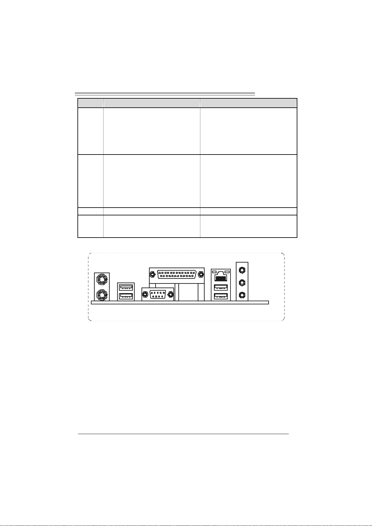
1.4 REAR PANEL CONNECTORS
PS/2
Mo use
Print er Po rt
LAN
Line In/
Su rrou nd
PS/ 2
Ke yboar d
Line Out
Mic In 1/
Bass/ Center
COM1 U SBX2USBX2
5
Page 6
Motherboard Manual
A
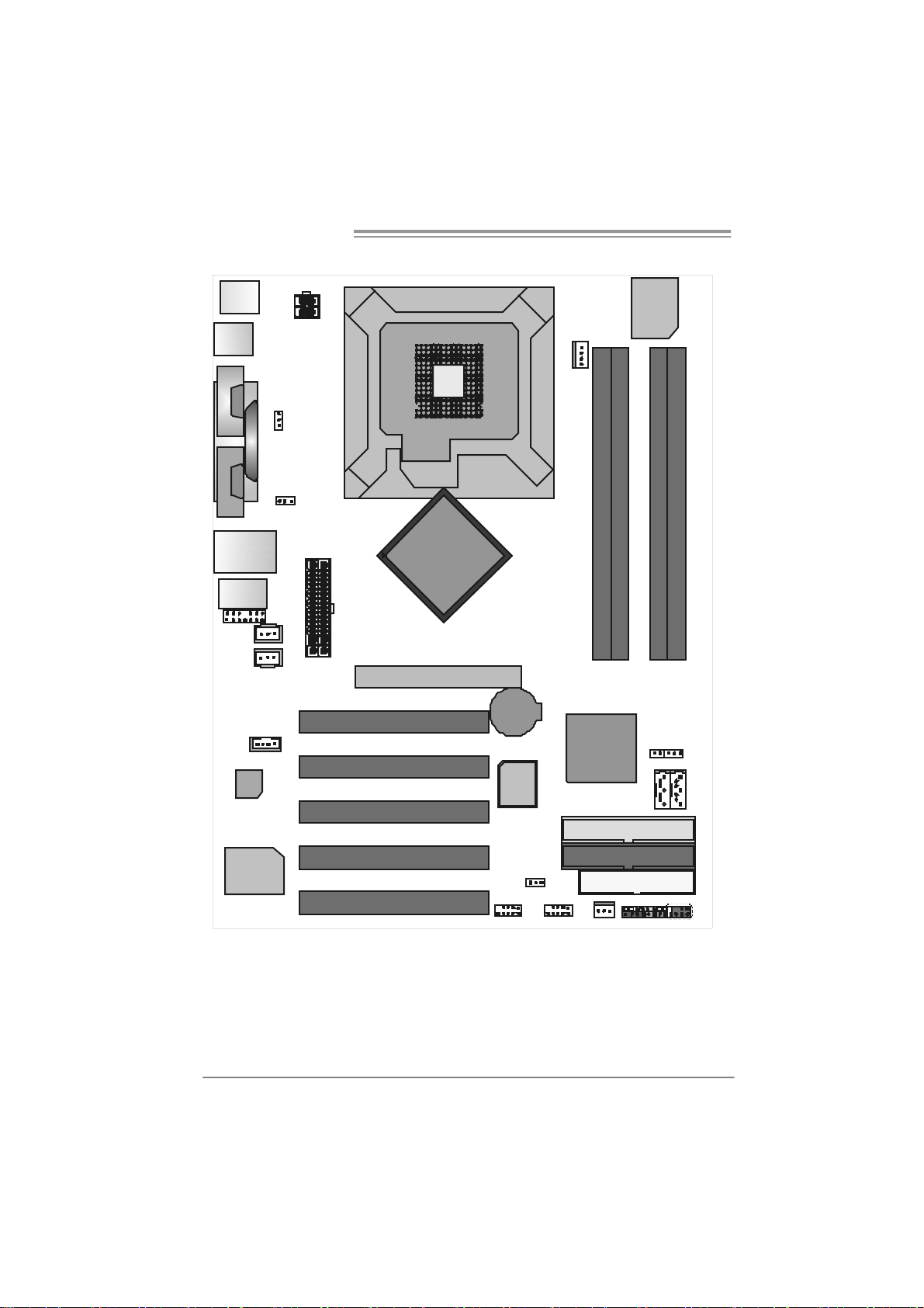
1.5 MOTHERBOARD LAYOUT (VER 1.0)
JK BM S 1
J ATXPWR 2
Super
I/ O
JUSB1
JC OM 1
1
M
O
C
2
M
O
C
JC OM 2
(opti onal)
JRJ45USB 1
JAUDIO1
J AUDIO 2
JSPDIF_OUT1
JSPDIF_IN1
(o pti o na l )
Codec
Parallel Por t
JCDI N1
JUSBV2
J KB_USB V1
JATXPWR1
PCI1
PCI2
LGA775
Intel
865PE
GP1
BAT1
BIOS
JCFA N1
DD RA 1
Intel
ICH5
DDRA2
DD RB 1
J C I1 ( o pti o na l )
JSATA1 JSATA2
DDRB2
JC MOS1
6
LAN
Note: represents the 1■
PCI3
PCI4
PCI5
st
pin.
J USBV3_ 4
ID E1
IDE2
FDD1
JPANEL1
IR (optional)
JUSB3JUSB2
JSF AN1
Page 7

I86PE-A7
A
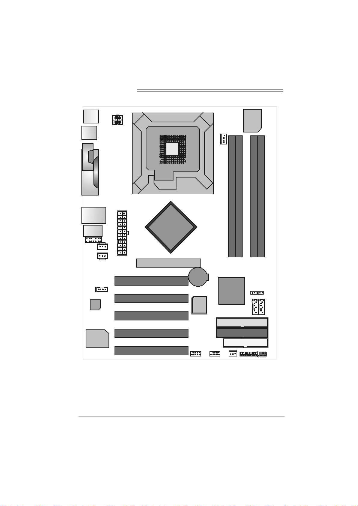
1.6 MOTHERBOARD LAYOUT (VER 7.0)
JC OM 1
Parallel Po rt
J CDIN 1
LAN
J ATXPWR 2
1
JK BMS1
JU SB 1
1
M
O
C
JRJ45USB 1
JAUDIO1
JAU DIO 2
JSPDIF_OUT1(optional)
JSPDIF_IN1(optional)
Codec
Note: represents the 1■
J ATXPWR 1
CP U1
PCI1
PCI2
PCI3
PCI4
PCI5
LGA775
Intel
865PE
GP1
st
pin.
BAT1
BIOS
Super
I/ O
JCFA N1
DDRA1
DDRA2
DDRB1
DDRB2
Intel
ICH5
JUSB3JUSB2
JSF AN1
ID E1
IDE2
FDD1
1
JCI1 (o ptional)
JSATA1 JSATA2
IR (Optional )
JPANEL1
JCMO S1
77
7
Page 8
Motherboard Manual
A
1.7 MOTHERBOARD LAYOUT (VER 7.1)
JC OM 1
Parallel Po rt
J CDIN 1
LAN
J ATXPWR 2
1
JK BMS1
JU SB 1
1
M
O
C
JRJ45USB 1
JAUDIO1
JAU DIO 2
JSPDIF_OUT1(optional)
JSPDIF_IN1(optional)
Codec
Note: represents the 1■
JATXPWR1
CP U1
PCI1
PCI2
PCI3
PCI4
PCI5
LGA775
Intel
865PE
GP1
st
pin.
BAT1
BIOS
Super
I/ O
JCFA N1
DDRA1
DDRA2
DDRB1
DDRB2
Intel
ICH5
JUSB3JUSB2
JSF AN1
ID E1
IDE2
FDD1
1
JCI1 (o ptional)
JSATA1 JSATA2
IR (Optional )
JPANEL1
JCMO S1
77
8
Page 9
I86PE-A7
CHAPTER 2: HARDWARE INSTALLATION
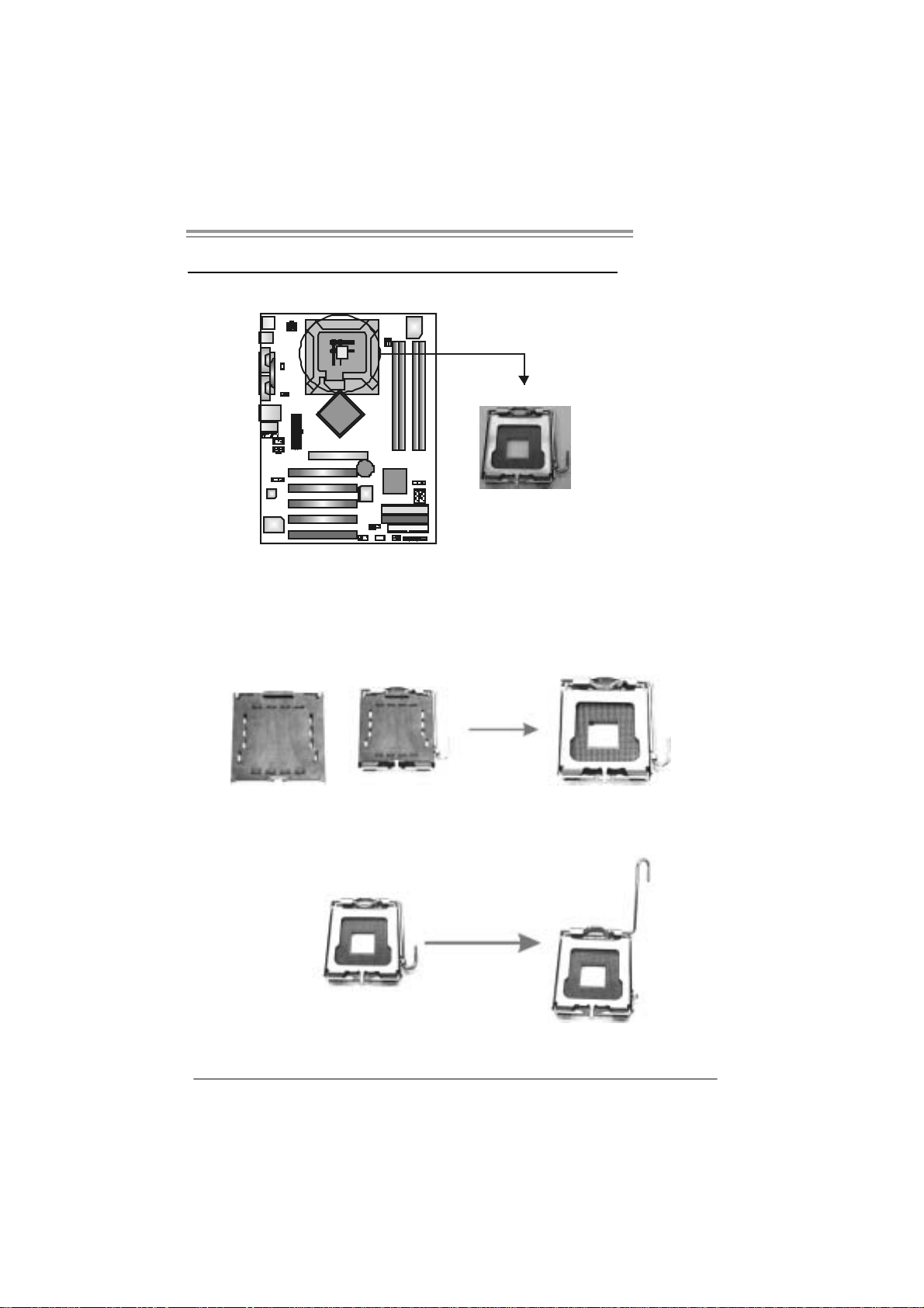
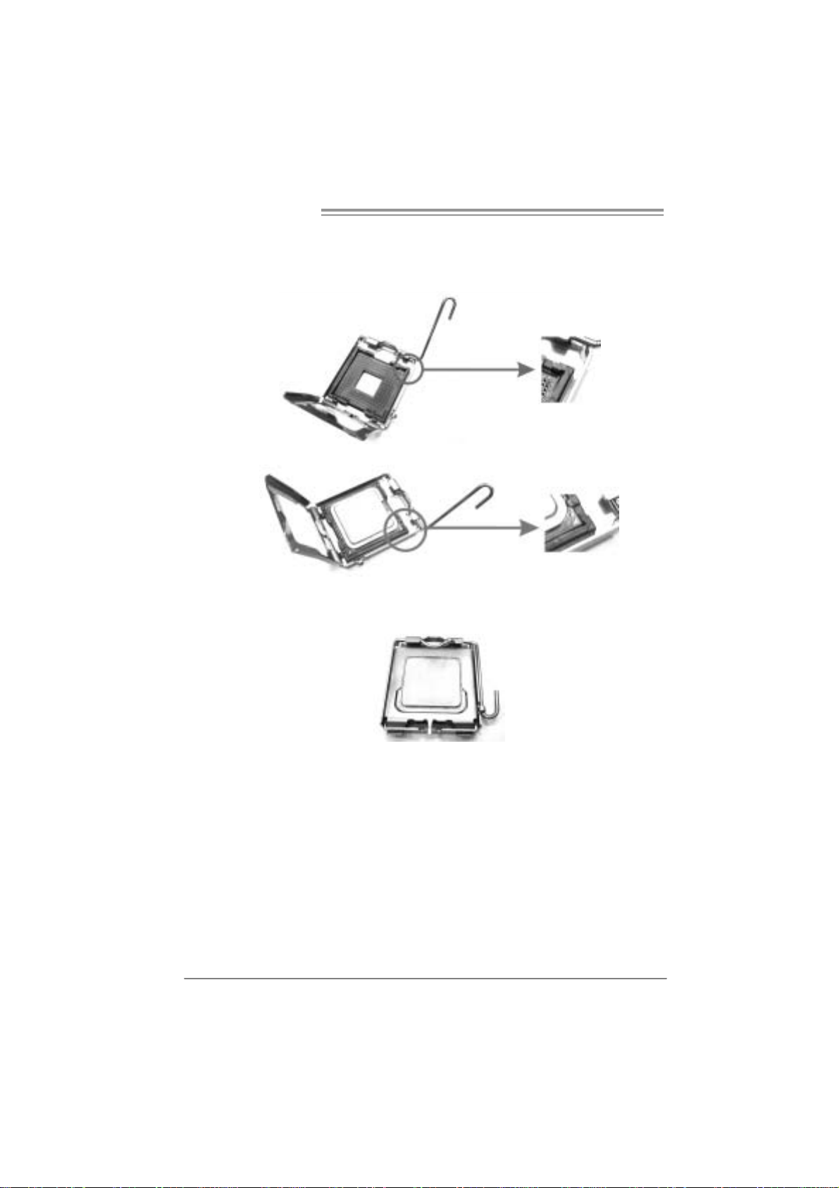
2.1 INSTALLING CENTRAL PROCESSING UNIT (CPU)
Special Notice:
Remo v e Pin Cap before installation, and ma ke goo d preservation for
future use. When the CPU is removed, cov er the Pin Cap on the empty
socket to ensure pin legs won’ t be damaged.
Pin Cap
Step 1: Pull the socket locking lever out from the socket
and then raise the lever up to a 90-degree angle.
9
Page 10
Motherboard Manual
Step 2: Look for the triangular cut edge on socket, and the golden dot on
CPU should point forwards this triangular cut edge. The CPU will
fit only in the correct orientation.
Step 2-1:
Step 2-2:
Step 3: Hold the CPU down firmly, and then lower the lever to locked
position to compl ete the installation.
Step 4: Put the CPU Fan and heatsink assembly on the CPU and buckle it
on the retention frame. Connect the CPU FAN power cable into
the JCFAN1. T his completes the installation.
10
Page 11
I86PE-A7
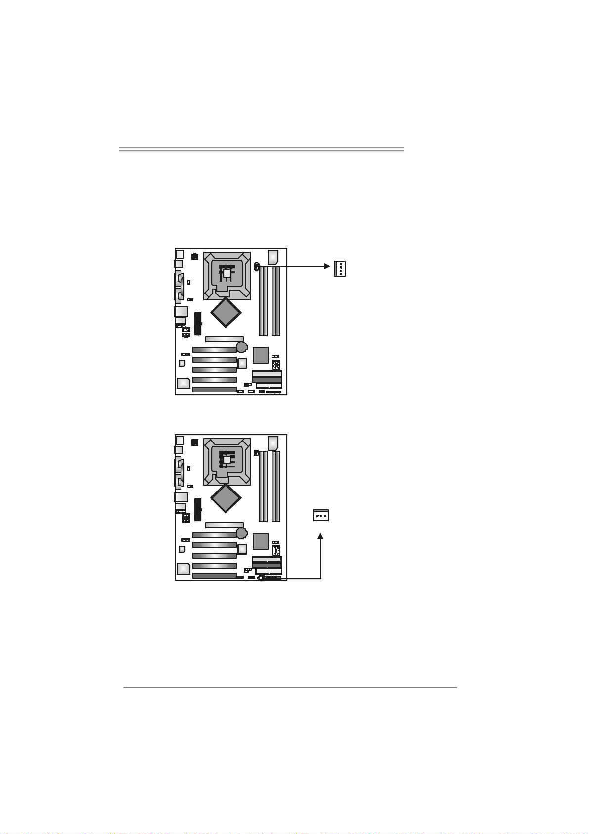
2.2 FAN HEADERS
These fan headers support cooling-fans built in the computer. The fan
cable and connector may be different according to the fan manufacturer.
Connect the fan cable to the connector while matching the black wire to
pin#1.
JCFAN1: CPU Fa n Header
Pin
Assignment
1 Ground
2 Smart Fan
Control
3 FAN RPM rate
sense
4 Smart Fan
Control
Assignment
Pin
1 Ground
2 +12V
3 FAN RPM rate
sense
JSF AN1 : Syst em F an H ead er
JCFA N1
JSFAN1
1
3
1
4
Note:
The J CFAN 1 a nd JSF AN 1 s uppor t 4-pin and 3-pi n h ead connec tor . W hen connecti ng
with wi r es onto c onn ectors, pl e ase note that t he re d wir e i s t he pos iti ve and s houl d be
conn ecte d t o pi n# 2, and th e bl ac k wi r e is Gr o und a nd s houl d b e c onnect ed to GND .
11
Page 12
Motherboard Manual
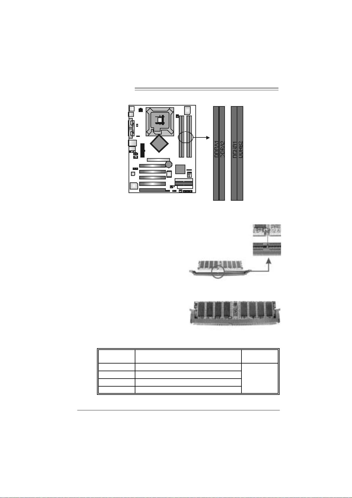
2.3 INSTALLING SYST EM MEMORY
1. Unlock a DIMM slot by pressing the retaining clips outward. Align a
DIMM on the slot such that the notch on the DIMM matches the
break on the Slot.
2. Insert the DIMM vertically and firmly into the slot until the retaining
chip snap back in place and the DIMM is properly seated.
B. Memory Capacity
DI MM Socket
Location
DDRA1 128MB/256MB/512MB/1GB *1
DDRA2 128MB/256MB/512MB/1GB *1
DDRB1 128MB/256MB/512MB/1GB *1
DDRB2 128MB/256MB/512MB/1GB *1
12
DDR Module
To t a l Me m ory
Size
Max is 4GB.
Page 13
I86PE-A7
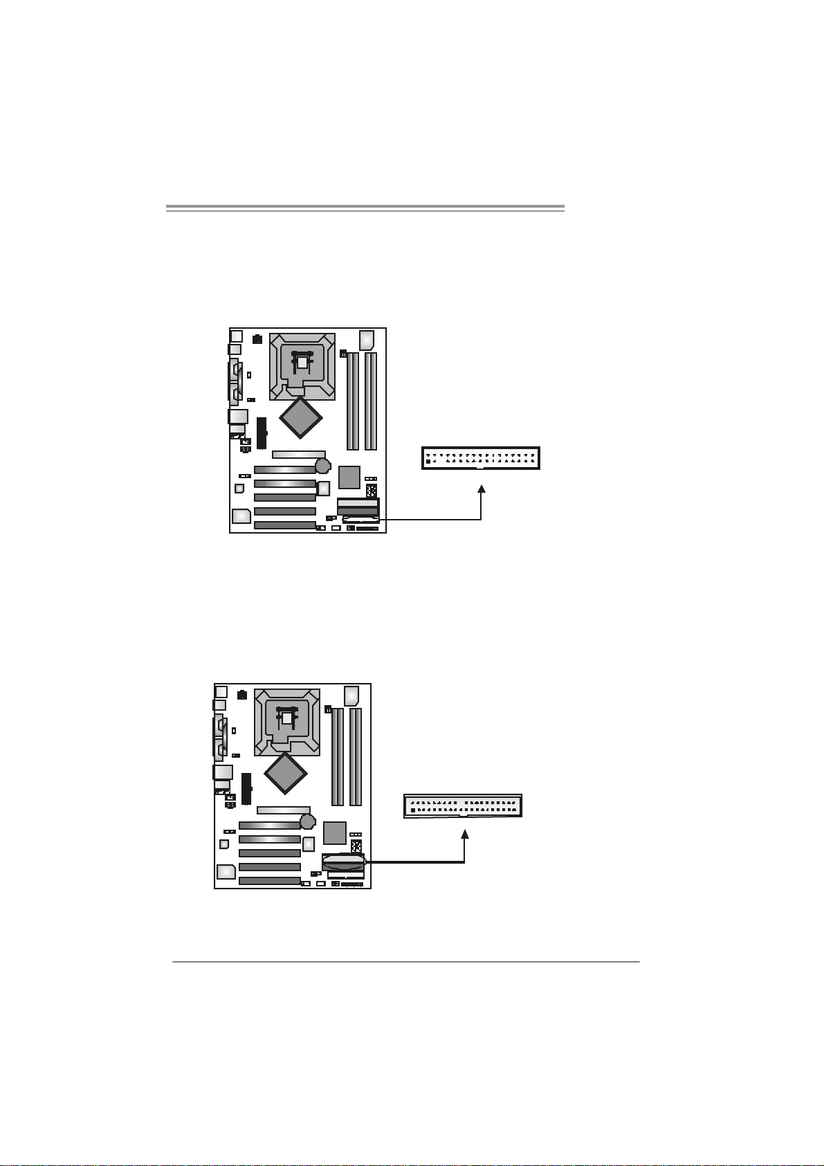
2.4 CONNECTORS AND SLOTS
FDD1: Floppy Disk Connecto r
The motherboard prov ides a standard floppy disk c onnector that supports 360K,
720K, 1.2M, 1.44M and 2.88M floppy disk ty pes. This connector supports the
prov ided f loppy drive ribbon cables.
IDE1 / IDE2 : H ar d Disk Connec tors
The motherboard has a 32-bit Enhanced PCI IDE C ont roller that prov ides PIO
Mode 0~4, Bus Mas ter, and Ultra DMA 33/66/100 functionality. It has two H DD
connectors IDE1 (primary) and IDE2 (secondary).
The IDE connectors can connect a master and a slav e driv e, so you can
connect up to four hard disk drives. The f irst hard drive should always be
connected to IDE1.
2
1
34
33
IDE1
2
1
4
0
3
IDE2
9
13
Page 14
Motherboard Manual
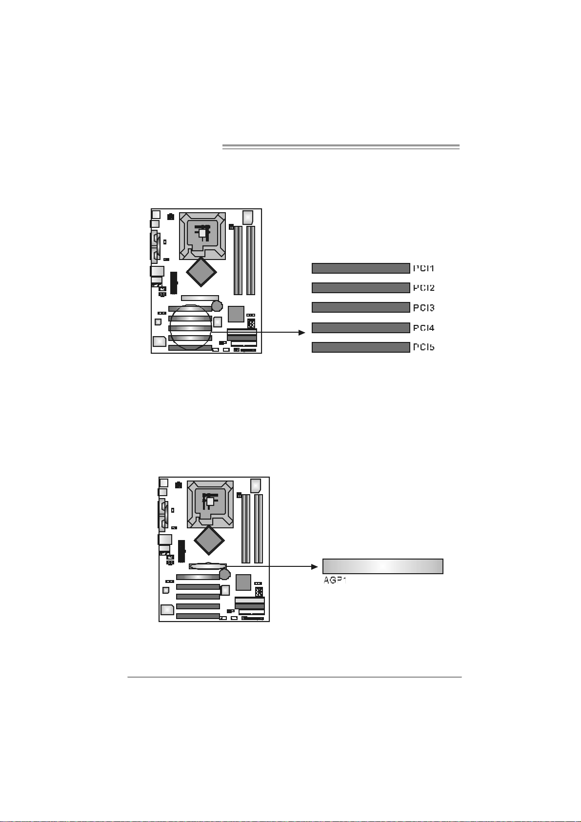
PCI1~PC I5: Peri pheral Component Interconne ct Sl o ts
This motherboard is equipped with 5 standard PCI s lots. PCI stands f or
Peripheral Component Interconnect, and it is a bus standard for expansion
cards. This PCI slot is designated as 32 bits.
AGP1 : Accele rat e d Graphics Port Slot
Your monitor will attach directly to that video card. This motherboard supports
video cards for PCI s lots, but it is also equipped with an Accelerated Graphics
Port (AGP). An AGP card will take adv antage of AGP technology for improv ed
video efficiency and performance, especially with 3D graphics.
14
Page 15
I86PE-A7
CHAPTER 3: HEADERS & JUMPERS S ETUP
3.1 HOW TO SET UP JUMPERS
The illustration shows how to set up jumpers. When the jumper cap is
placed on pins, the jumper is “close”, if not, that means the jumper is
“open”.
Pin opened Pin closed Pin1-2 closed
3.2 DETAIL SETT INGS
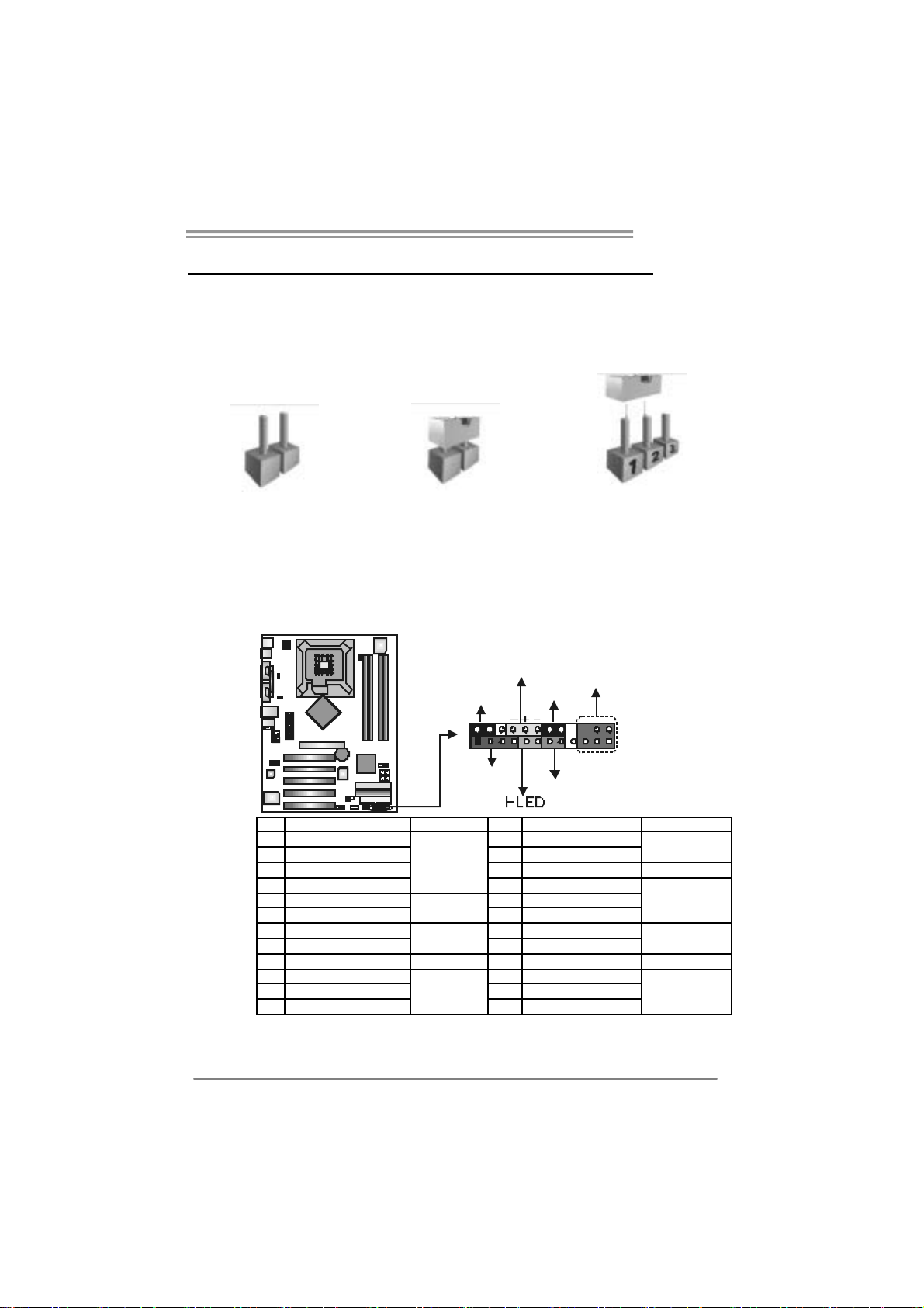
JPANEL1: Front Panel Header (for Ve r 1.x an d Ver 7.0)
This 24-pin connector includes Power-on, Reset, HDD LED, Power LED, Sleep
button, speaker and IrDA Connect ion. It allows user to connect t he PC case’s
front panel switch f unctions.
PWR_LED
SLP
2
1
SPK
On/Off
_
+
RST
IR(opt ional)
24
23
Pin Assignment Functio n Pin Assignment Function
1 +5V 2 Sleep control
3 N/A 4 Ground
5 N/A 6 N/A N/A
7 Speaker
9 HDD LED (+) 10 Power LED (+)
11 HDD LED (-)
13 Ground 14 Power button
15 Reset control
17 N/A 18 Key
19 N/A 20 Key
21 +5V 22 Ground
23 IRTX
Speaker
Connector
Hard drive
LED
Reset button
IrDA
Connector
8 Power LE D (+)
12 P ower L ED (-)
16 Ground
24 IRRX
Sleep button
Power LED
Power-on button
IrDA Connector
15
Page 16
Motherboard Manual
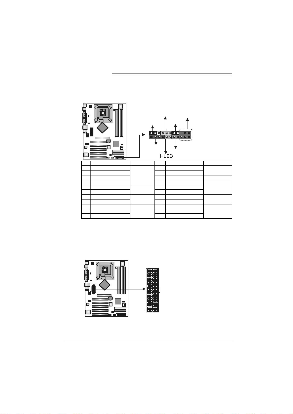
JPANEL1: Front Panel Header (for Ve r 7.1)
This 24-pin connector includes Power-on, Reset, HDD LED, Power LED, Sleep
button, speaker and IrDA Connect ion. It allows user to connect t he PC case’s
front panel switch f unctions.
12
1
Pin Assignment Functio n Pin Assignment Function
1 +5V 12 Sl eep control
2 N/A 13 Ground
3 N/A 14 N/A N/A
4 Speaker
5 HDD LED (+) 16 Power LED (+)
6 HDD LED (-)
7 Ground 18 Power button
8 Reset control
9 N/A 20 Key
10 +5V 21 Ground
11 IRTX
Speaker
Connector
Hard drive
LED
Reset button
IrDA
Connector
JAT XPWR1: A TX Powe r S ou rce C onnector
This connector allows user to connect 20-pin power connector on the ATX
power supply.
10
16
PWR_LED
SLP
On/Off
_
+
SPK
15 P ower L ED (+)
17 P ower L ED (-)
19 Ground
22 IRRX
20
11
IR(opt ional)
22
11
RST
Sleep button
Power LED
Power-on button
IrDA Connector
Pin Assignment
1 +3.3V
2 +3.3V
3 Ground
4 +5V
5 Ground
6 +5V
7 Ground
8 PW_OK
9 Standby Voltage
+5V
10 +12V
11 +3.3V
12 -12V
13 Ground
14 PS_ON
15 Ground
16 Ground
17 Ground
18 -5V
19 +5V
20 +5V
Page 17
I86PE-A7
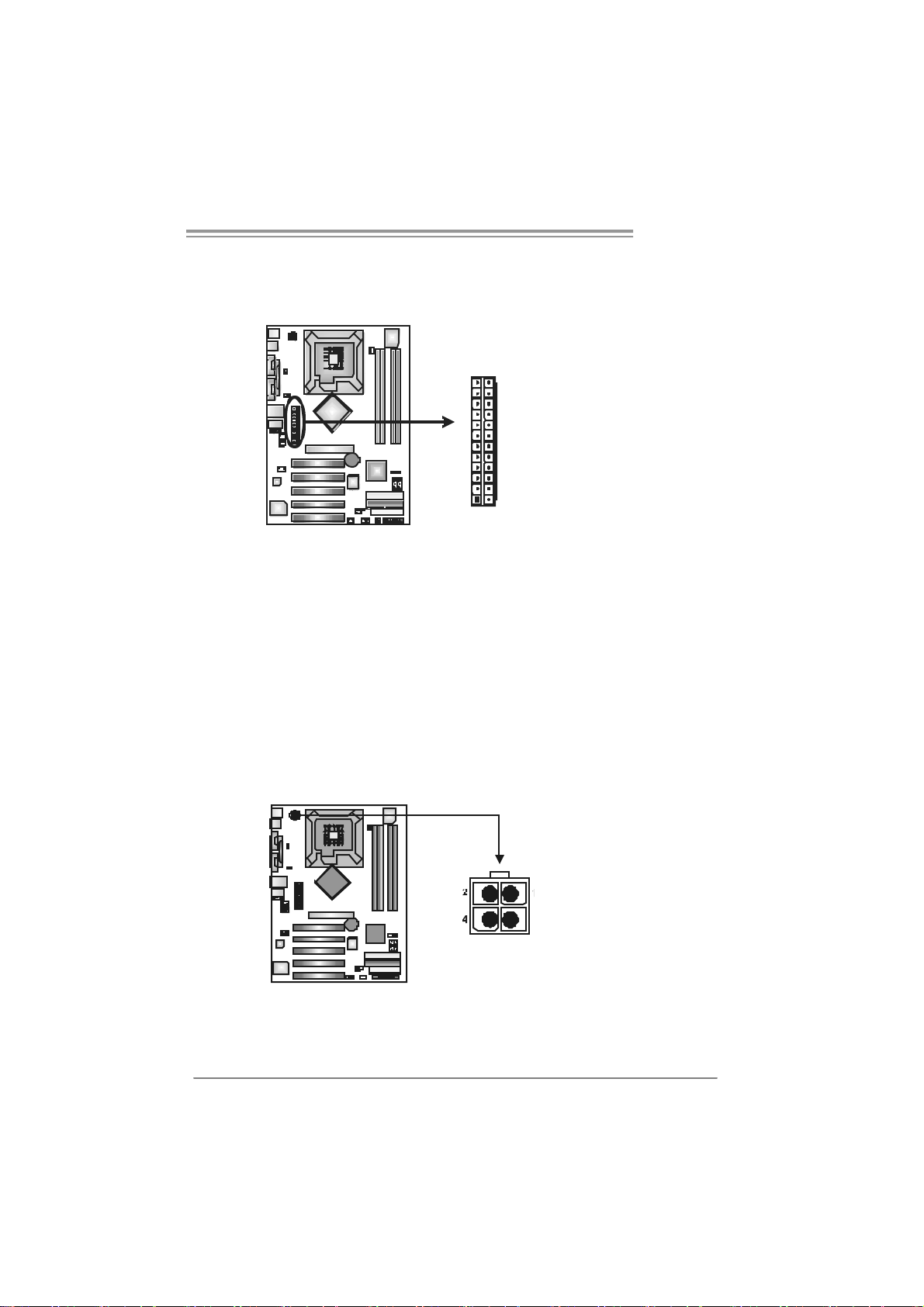
AT X Power Source Co n n ec t or : JATX P WR1 (Ver 7.1 on ly)
JATXPWR1 allows user to connect 24-pin power connector on the ATX power
supply.
12
24
1
13
Pin Assignment Pin Assignment
13 +3.3V 1 + 3.3V
14 -12V 2 + 3.3V
15 Gr oun d 3 Groun d
16 PS_ON 4 + 5V
17 Gr oun d 5 Groun d
18 Gr oun d 6 + 5V
19 Gr oun d 7 Groun d
20 NC 8 PW_ OK
21 +5V 9 Standby Volt ag e+5V
22 +5V 10 +12V
23 +5V 11 +12V
24 Gr oun d 12 + 3.3V
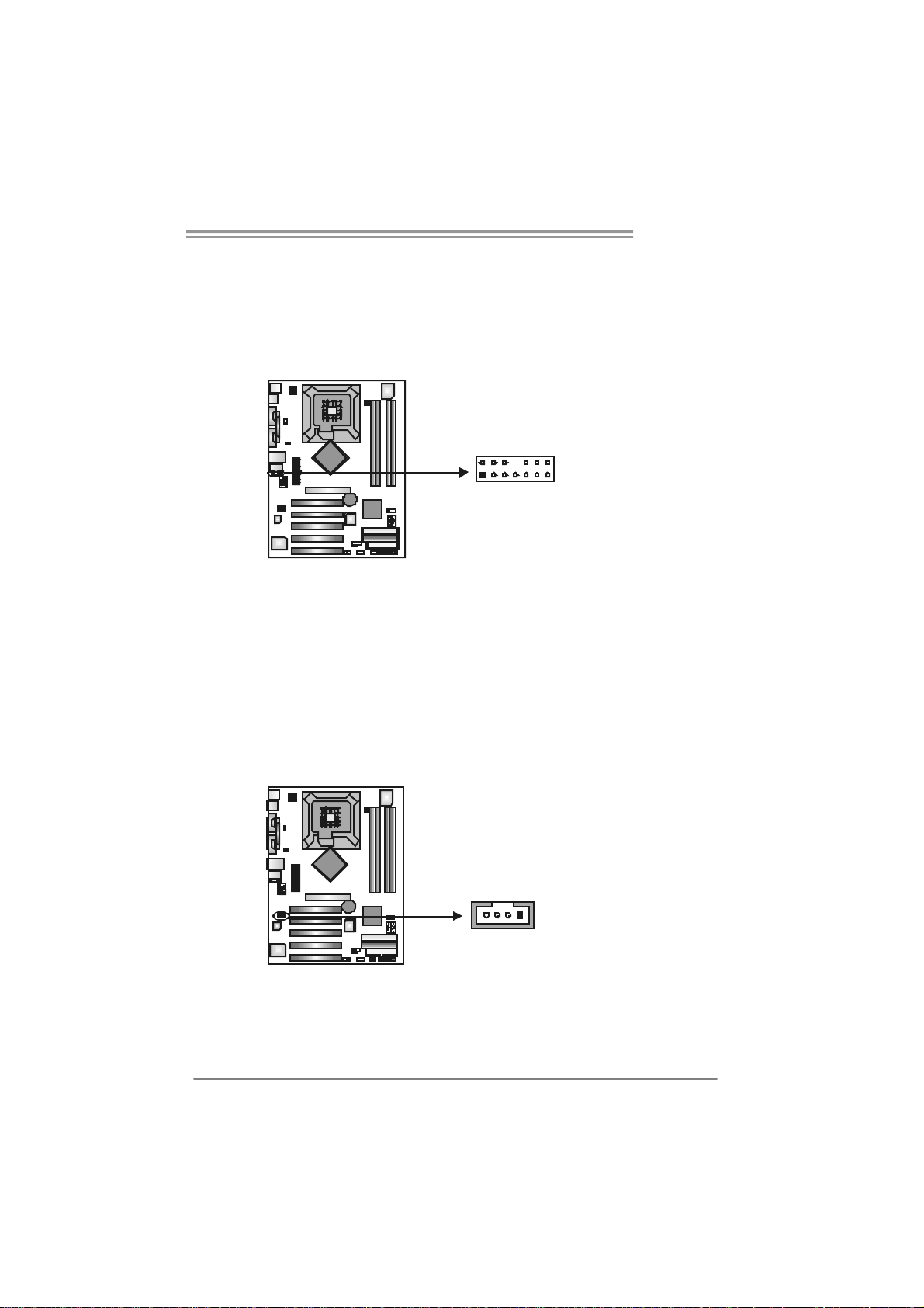
JAT XPWR2: A TX Powe r S ou rce C onnector
By connecting this connect or, it will provide +12V t o CPU power circuit.
Pin
3
Assignment
1 +12V
2 +12V
3 Ground
4 Ground
17
Page 18
Motherboard Manual
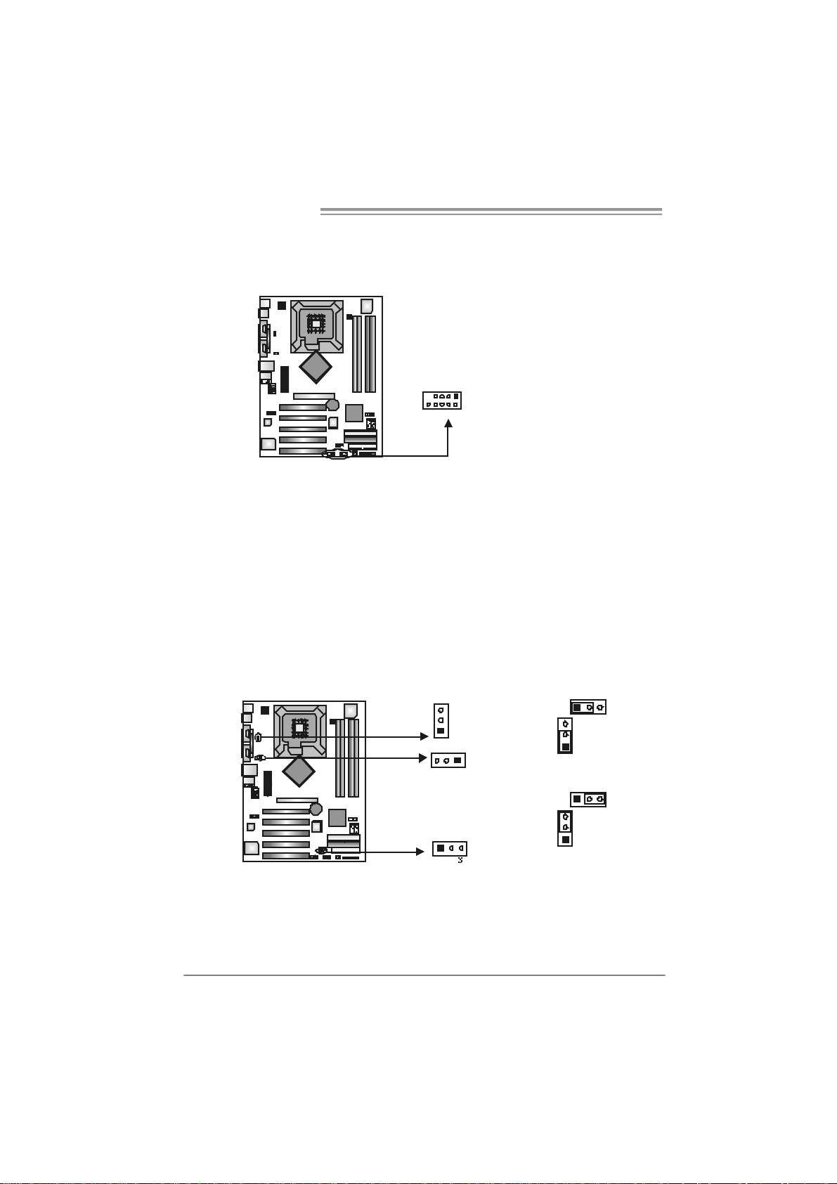
JUSB2/JUSB3: Headers for 2.0 Ports at Front USB Panel
This motherboard provides 2 USB 2.0 headers, which allows user to connect
additional USB cable on the PC front panel, and also can be connected with
internal USB devices, like USB card reader.
Assignment
Pin
1 +5V (fused)
2 +5V (fused)
3 USB4 USB5 USB+
6 USB+
7 Ground
8 Ground
9 Key
10 NC
JUSB1 JUSB2
1
210
JKB_USB V1/JUSBV2/JUSBV3_4: Power Source He ade rs for PS /2
and USB Ports (Ver 1.x only)
Pin 1-2 Clo se:
JKB_USBV1: +5V for JKBMS1 and JUSB1.
JUSBV2: +5V for JUSBLAN1.
JUSBV3_4: +5V for JUSB2/3.
Pin 2-3 Clo se:
JKB_USBV1: JKBMS1 and JUSB1 are powered with +5V standby v oltage.
JUSBV2: JUSBLAN1 is powered by +5V standby voltage.
JUSBV3_4: JUSB2/3 are powered by +5V standby v oltage.
3
JKB_USBV1
1
13
JUSBV2
JUSBV3_4
1
Note:
In or d er to su pport this f unc tion “Po wer-on s yste m via keyboar d and mouse”,
“JUSBV1/JUS BV2 /JUSBV 3_ 4” jum per c ap s ho uld be placed on Pin 2- 3.
3
1
3
1
31
Pin 1-2 close
1
3
Pin 2-3 close
18
Page 19
I86PE-A7
JFAUDIO1 : Fron t Panel Audio Header
This header allows user to connect the front audio output cable with the PC f ront
panel. It will disable the output on back panel audio connectors.
Pin Assignment
1 Mic i n/center
2 Ground
3 Mic power/Bass
4 Audio power
5 Ri ght li ne out/
Speaker out Right
6 Ri ght li ne out/
Speaker out Right
2
1
7 Reserved
14
8 Key
9 Left l ine out/
13
10 Left line out/
11 Right line in/
12 Right li ne in/
13 Left line in/
14 Left line in/
Speaker out Left
Speaker out Left
Rear speaker Right
Rear speaker Right
Rear speaker Left
Rear speaker Left
JCDIN1: CD-R OM A ud io-in Connector
This connector allows user to connect the audio source from the v ariaty dev ices,
like CD-ROM, DVD-ROM, PCI sound card, PCI TV turner card etc..
Assignment
Pin
1 Left Channel Input
2 Ground
3 Ground
4 Right Channel Input
14
19
Page 20
Motherboard Manual
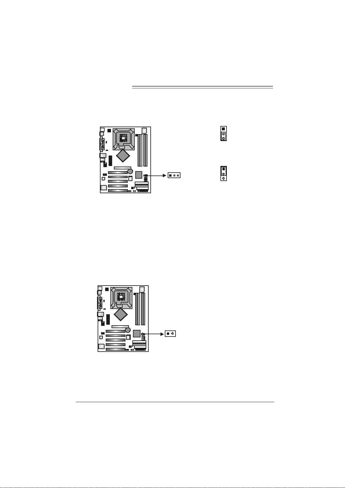
JCMOS 1 : C l ea r CMOS He a der
By placing the jumper on pin2-3, it allows user to restore the BIOS saf e setting
and the CMOS data, please carefully f ollow t he procedures to avoid damaging
the motherboard.
1
3
Pin 1-2 Close:
Normal Operation (default).
1
1 3
3
Pin 2-3 Close:
Clear CMOS data.
※ Clear CMOS Procedures:
1. Remove AC power line.
2. Set the jumper to “Pin 2-3 close”.
3. Wait for five seconds.
4. Set the jumper to “Pin 1-2 close”.
5. Power on the AC.
6. Reset y our desired password or clear the CMOS data.
JCI1: Chassis O pen Header
This connector allows system to monitor PC cas e open status. If the signal has
been triggered, it will record to the CMOS and s how the message on next
boot-up.
Pin
Assignment
1 Case open signal
2 Ground
21
20
Page 21
I86PE-A7
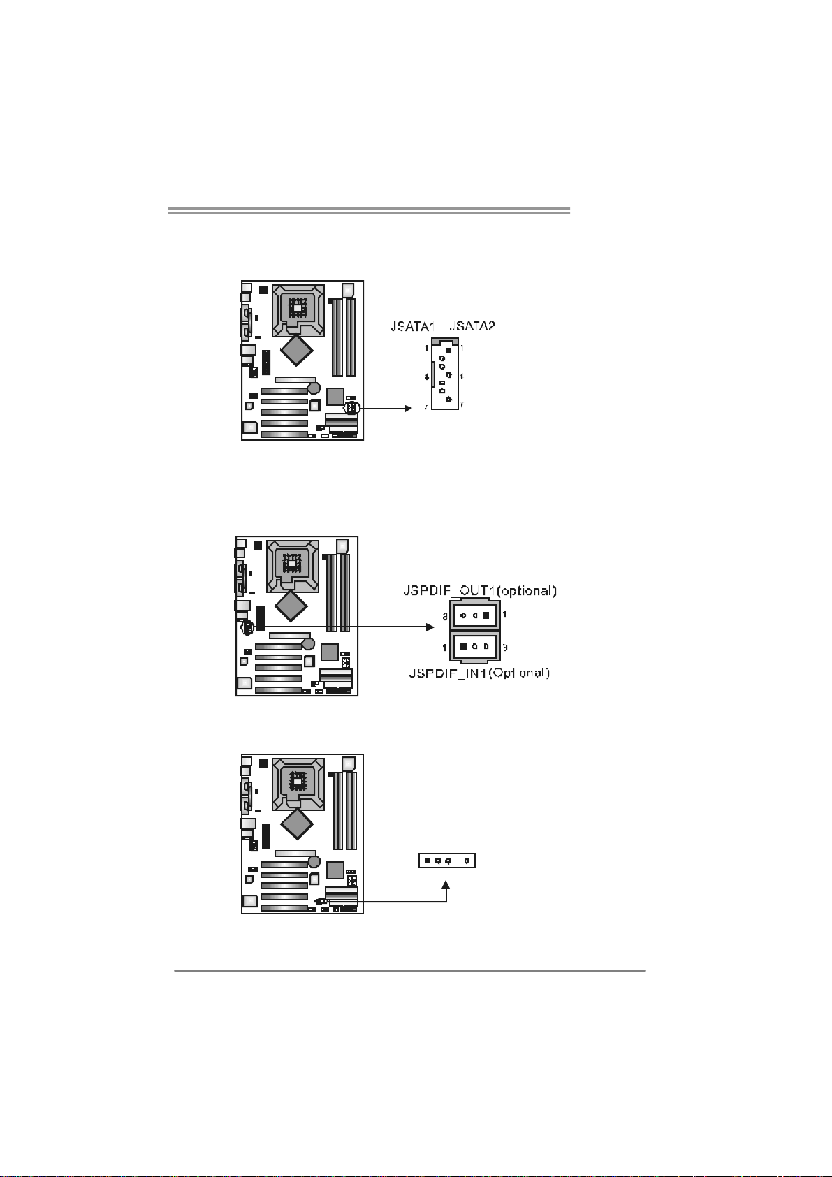
JSATA1 ~ JS ATA2: Serial ATA Connect o rs
The motherboard has a PCI to SATA C ontroller with 2 channels SATA int erf ace,
it satisfies the SATA 1.0 spec and with transfer rate of 1.5Gb/s.
Pin
Assignment
1 Ground
2 TX +
3 TX 4 Ground
5 RX6 RX+
7 Ground
JSP DI F_ OUT1 (optiona l)/ J SPD I F _I N 1 (op ti o na l) : Dig it a l Audio-ou t
Connector
This connector allows user to connect the PCI bracket SPDIF output header.
Pin
Assignment
1 +5V
2 SPDIF_OUT
3 Ground
JDJ1 (optional) : AUDIO DJ Header
Pin
Assignment
1 SMBDATA
2 SMBCLK
5
1
3 INT_B
4 Key
5 AXT_PWROK
21
Page 22
Motherboard Manual
CHAPTER 4: USEFUL HELP
4.1 DRIVER INSTALLA TION NOTE
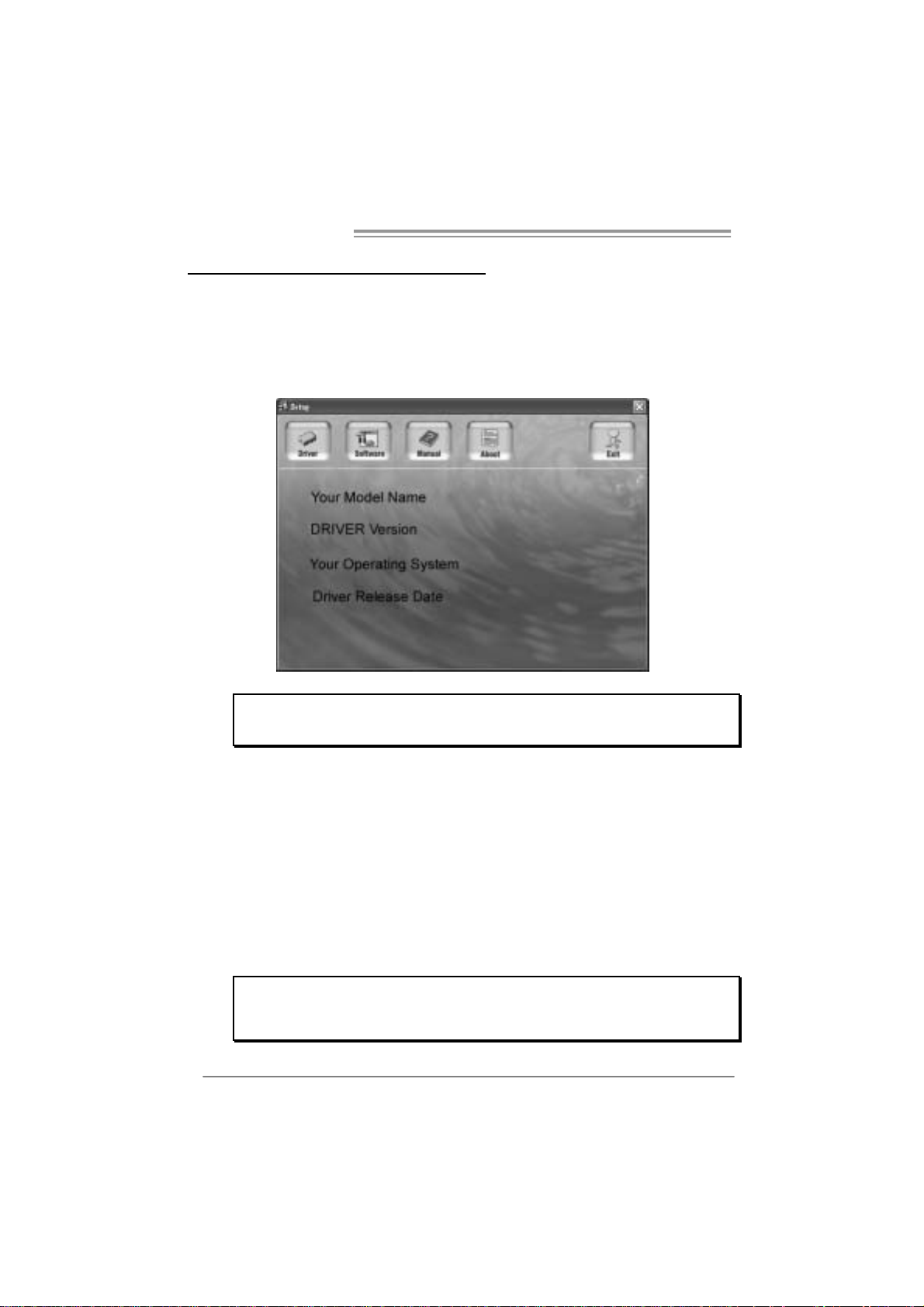
After you installed your operating system, please insert the Fully Setup
Driver CD into your optical drive and install the driver for better system
performance.
You will see the following window after you insert the CD
The setup guide will auto detect you r m otherboard and o perating system .
Note:
If this win do w didn’ t show up aft er yo u ins ert th e Dr iver C D, ple ase use fil e browser to
locate and e xecu te the fi le SETU P.E XE un der your o pti cal drive .
A. Driver Insta llation
To install the driver, please click on the Driver icon. The setup guide will
list the compatible driver for your motherboard and operating system.
Click on each device driver to launch the installation program.
B. Software Installatio n
To install the software, please click on the Software icon. The setup guide
will list the software available for your system, click on each software title
to launch the installation program.
C. Manual
Aside from the paperback manual, we also provide manual in the Driver
CD. Click on the Manual icon to browse for available manual.
Note:
You will need Acrobat Rea der to open the manual file. Please download the lat est version
of Acrob at Re ader software fr om
http://www.adobe.com/products/acrobat/readstep2.ht ml
22
Page 23
I86PE-A7
4.2 AWARD BIOS BEEP CODE
Beep Sound Meanin g
One long beep followed by two short
beeps
High-low siren sound C PU overheated
One Short beep when system boot-up No error found during POST
Long beeps every other second No DRAM detected or install
Video card not found or v ideo card
memory bad
System will shut down automatically
4.3 EXTRA INFORMATION
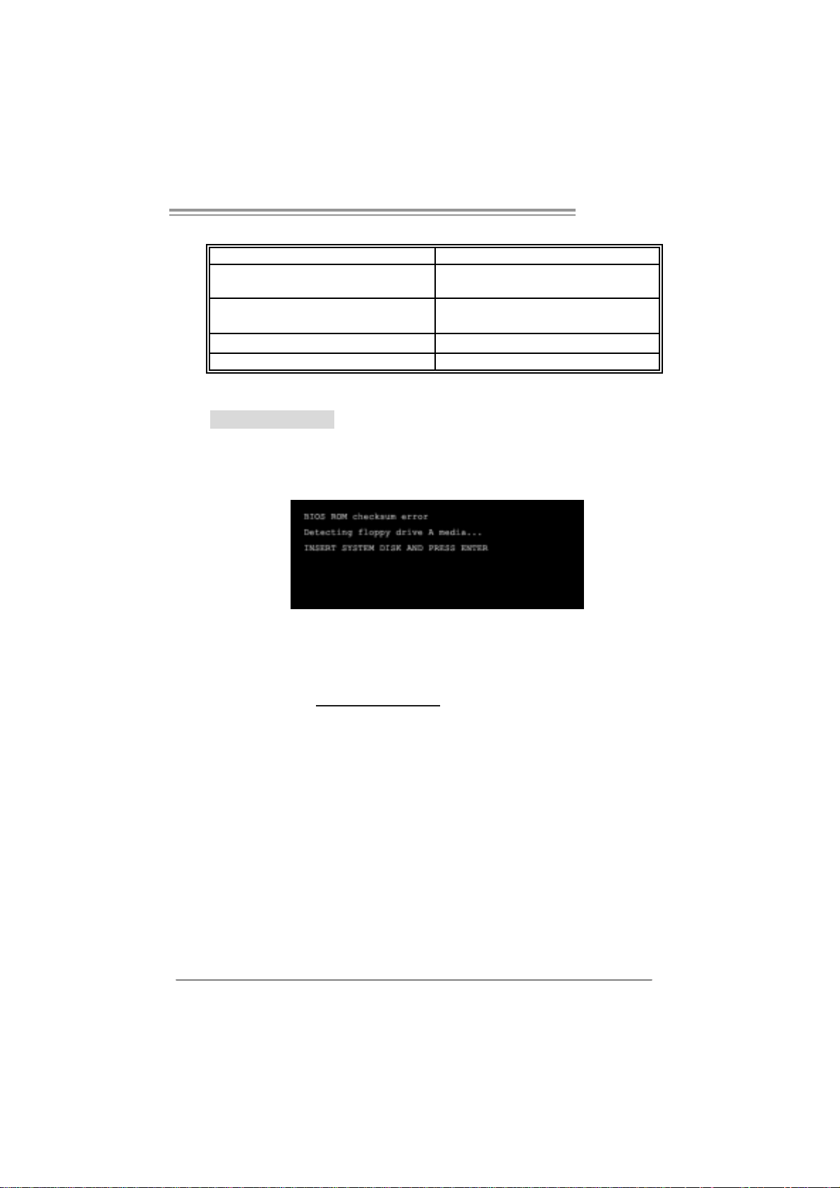
A. BIOS Update
After you fail to update BIOS or BIOS is invaded by virus, the
Boot-Block function will help to restore BIOS. If the following message
is shown after boot-up the system, it means the BIOS contents are
corrupted.
In this Case, please follow the procedure below to restore the BIOS:
1. Make a bootable floppy disk.
2. Download the Flash Utility “AWDFLASH.exe” from the Biostar
website: www.biostar.com.tw
3. Confirm motherboard model and download the respectively BIOS
from Biostar website.
4. Copy “AWDFLASH.exe” and respectively BIOS into floppy disk.
5. Insert the bootable disk into floppy drive and press Enter.
6. System will boot-up to DOS prompt.
7. Type “Awd flash xxxx.bf/sn/p y/ r” in DOS prompt.
(xxxx means BIOS name.)
8. System will update BIOS auto matically and restart.
9. The BIOS has been recovered and will wo rk properly.
23
Page 24

Motherboard Manual
B. CPU Overheated
If the system shutdown automatically after power on system for
seconds, that means the CPU protection function has been activated.
When the CPU is over heated, the motherboard will shutdown
automatically to avoid a damage of the CPU, and the system may not
power on again.
In this case, please double check:
1. The CPU cooler surface is placed evenly with the CPU surface.
2. CPU fan is rotated normally.
3. CPU fan speed is fulfilling with the CPU speed.
After confirmed, please follow steps below to relief the CPU protection
function.
1. Remove the power cord from power supply for seconds.
2 . Wa i t fo r se c o nd s.
3. Plug in the power cord and boot up the system.
Or you can:
1. Clear the CMOS data.
(See “Close CMOS Header: JCMOS1” section)
2 . Wa i t fo r se c o nd s.
3. Powe r on th e system agai n.
24
Page 25

I86PE-A7
e
4.4 TROUBLE SHOOTING
Probable Solution
1. No power to the system at all
Power light don’t illuminate, f an
inside power supply does not turn
on.
2. Indicator light on key board does
not turn on.
System inoperativ e. Keyboard lights
are on, power indicator lights are lit,
and hard driv e is spinning.
System does not boot from hard disk
driv e, can be booted f rom optical driv e.
System only boots f rom optical driv e.
Hard disk can be read and applications
can be used but booting from hard disk
is impossible.
Screen message says “Invalid
Configuration” or “CMOS Failure.”
Cannot boot system after installing
second hard drive.
1. Make sure power cable is
securely plugged in.
2. Replace cable.
3. Cont act technic al support.
Using even pressure on both ends of
the DIMM, press down firmly until the
module snaps into place.
1. Check cable running from disk to
disk controller board. Make sure
both ends are securely plugged
in; c hec k t h e d r iv e ty pe i n t he
standard CMOS setup.
2. Backing up the hard drive is
extremely important. All hard
disks are capable of breaking
down at any time.
1. Back up data and applications
files.
2. Ref ormat the hard driv e.
Re-install applications and data
using backup disks.
Review system’s equipment. Make sur
correct inf ormation is in setup.
1. Set master/slave jumpers
correctly.
2. Run SETUP program and select
correct driv e types. Call the drive
manufacturers for compatibility
with other drives.
25
Page 26

Motherboard Manual
CHAPTER 5: WARPSPEEDER ™
5.1 INTRODUCTION
[WarpSpeeder™], a new powerful control utility, features three
user-friendly functions including Overclock Manager, Overvoltage
Manager, and Hardware Monitor.
With the Overclock Manager, users can easily adjust the frequency they
prefer or they can get the best CPU performance with just one click. The
Overvoltage Manager, on the other hand, helps to power up CPU core
voltage and Memory voltage. The cool Hardware Monitor smartly indicates
the temperatures, voltage and CPU fan speed as well as the chipset
information. Also, in the About panel, you can get detail descriptions about
BIOS model and chipsets. In addition, the frequency status of CPU,
memory, AGP and PCI along with the CPU speed are synchronically
shown on our main panel.
Moreover, to protect users' computer systems if the setting is not
appropriate when testing and results in system fail or hang,
[WarpSpeeder™] technology assures the system stability by automatically
rebooting the computer and then restart to a speed that is either the
original system speed or a suitable one.
5.2 SYSTEM REQU IREMENT
OS Support: Windows 98 SE, Windows Me, Windows 2000, Windows XP
DirectX: DirectX 8.1 or above. (The Windows XP operating system
includes DirectX 8.1. If you use Windows XP, you do not need to install
DirectX 8.1.)
26
Page 27

I86PE-A7
5.3 INSTALLATION
1. Execute the setup execution file, and then the following dialog will pop
up. Please click “Next” button and follow the default procedure to
install.
2. When you see the following dialog in setup procedure, it means setup
is completed. If the “Launch the WarpSpeeder Tray Utility” checkbox
is checked, the T ra y Icon utility and [WarpSp eeder™] utility will b e
automatically and immediately launched after you click “Finish”
button.
Usage:
The following figures are just only for reference, the screen printed in
this user manual will chang e accordin g to your m otherboa rd on hand.
27
Page 28

Motherboard Manual
5.4 WARPSPEEDER™
1. Tray Icon:
Whenever the Tray Icon utility is launched, it will display a little tray
icon on the right side of Windows Taskbar.
This utility is responsible for conveniently invoking [WarpSpeeder™]
Utility. You can use the mouse by clicking the left button in order to
invoke [WarpSpeeder™] directly from the little tray icon or you can
right-click the little tray icon to pop up a popup menu as following
figure. The “Launch Utility” item in the popup menu has the same
function as m ouse left-cli ck on tray icon and “Exit” i tem will close
Tray Icon utility if selected.
28
Page 29

I86PE-A7
2. Main Panel
If you cli ck the tray icon, [WarpSpeeder™] util ity will b e i nvo ked.
Please refer to the following figure; the utili ty’s first window you will
see is Main Panel.
Main Panel contains features as follows:
a . Di sp l a y t he CP U Sp ee d, CP U e xte rnal cl o ck, M em ory cl o ck, A G P cl ock,
and PCI clock information.
b. Contains About, Voltage, Overclock, and Hardware Monitor Buttons for
invoking respective panels.
c. With a user-friendly Status Animation, it can represent 3 overclock
percentage stages:
Man walking→overclock percentage from 100% ~ 110 %
Panther running→overclock percentage from 110% ~ 120%
Car racing→overclock percentage from 120% ~ above
29
Page 30

Motherboard Manual
3. Vol tage Panel
Click the Voltage button in Main P anel , the button will be hi g hlighted
an d the Volta ge Panel will slide out to up as the followi ng fig ure.
In this panel, you can decide to increase CPU core voltage and
Memory voltage or not. The default setting is “No”. If you want to get
the best performance of overclocking, we recommend you click the
option “Yes”.
30
Page 31

I86PE-A7
4. Over clock Panel
Click the Overcl o ck button in Main Panel, the butto n will be
highlighted and the Overclock Panel will slide out to left as the
following figure.
Overclock Panel cont ains the the se features:
a. “–3MHz button”, “-1MHz button”, “+1MHz button”, and “+3MHz button”:
provide user the ability to do real-time overclock adjustment.
Warning:
Manually overclock is potentially dangerous, especially when the
ov erclocking percentage is over 110 %. We strongly recommend you
v erify ev ery speed you overc loc k by click the Verify button. Or, you can
just click Auto ov erclock button and let [WarpSpeeder™] automatically
gets the best result f or y ou.
b. “Recovery Dialog button”: Pop up the following dialog. Let user select
a restoring way if system need to do a fail-safe reboot.
31
Page 32

Motherboard Manual
c. “Auto-overclock button”: User can click this button and
[WarpSpeeder™] will set the best and stable perfo rmance and
frequency automatically. [WarpSpeeder™] utility will execute a
se ri es of testing until system fail. Then system will do fail-safe
reboot by using Watchdog function. After reboot, the
[WarpSpeeder™] utility will restore to the hardware default
setting or load the verified best and stable frequency according
to the Recovery Dial og’s setting.
d. “Verify button”: User can click this button and [WarpSpeeder™]
will proceed a testing for current frequency. If the testing is ok,
then the current frequency will be saved into system registry. If
the testing fail, system will do a fail-safe rebooting. After reboot,
the [WarpSpeeder™] utili ty will restore to the hard ware default
setting or load the verified best and stable frequency according
to the Recovery Dial og’s setting.
Note:
Because the testing programs, invoked in Auto-overclock and Verify,
include DirectDraw, Direct3D and D irectShow tests, the DirectX 8.1 or
newer runtime library is required. And please mak e s ure your display
card’s color depth is High color (16 bit) or True color( 24/32 bit ) that is
required f or Direct3D rendering.
5. Hardware Monitor Panel
Click the Hardware Moni tor button i n Main Panel, the b utton will be
highlighted and the Hardware Monitor panel will slide out to left as
the following figure.
In this panel, you can get the real-time status information of your
sy stem . T he in formati o n will be refre shed every 1 second.
32
Page 33

I86PE-A7
6. About Panel
Click the “about” button in Main Panel, the button will be highlighted
and the About Panel will slide out to up as the following figure.
In this panel, you can get model name and detail information in hints
of all the chipset that are related to overclocking. You can also get
the mainboard’s BIOS model and the Version number of
[WarpSpeeder™] utility.
Note:
Because the overclock, overvoltage, and hardware monitor features
are controlled by several separate chipset, [WarpSpeeder™] divide
these features to separate panels. If one chipset is not on board, the
co rrel ati ve b u t ton in Mai n panel will be di sabl ed, bu t will no t i nterfe re
other panels’ functions. This property can make [WarpSpeeder™]
utili ty mo re robust.
33
Page 34

Motherboard Manual
/
/
APPENDENCIES: SPEC IN OTHER LANGUAGE
GERMAN
Ve r 1.0 & Ver 7.0 Ver 7.1
LGA 77 5
Intel Pentium 4 / Pentium D / Celeron D
CPU
FS B 533 / 800 MHz 533 / 800 M Hz
Chipsatz
Super E/A
Arbeitsspeic
her
IDE
SATA II
LAN
Audio-Code
c
Steckplätze
Onboard-A n
schluss
Prozessoren mit bis zu 3,8 GHz
(Unterstützt keine Cedar Mill & Presler
CPUs)
Int el 865P E
Intel ICH5
ITE 871 2F
Hardware-Üb erwachung
Lüfterdrehzahl-Controller
"Smart Guar dian" -Funktion von ITE
DDR DIMM-Stec kplätze x 4
Jeder DIMM unterstützt 128
1GB DDR
Max. 4GB Arbeitsspeicher
Dual-Kanal D DR Speic hermodul
Unt erst üt zt DDR 2 66 / 333 / 40 0
Integrierter IDE-Controller
Ultr a DMA 33 / 66 / 100 Bus M as ter-Modus
Unterstützt PIO-Modus 0~4
Integrierter Serial ATA-Controller
Datentrans ferr ate bis z u 1.5Gb/s
Konform mit der SATA-Spezifikation
Vers ion 1.0
Realt ek 8100C
10 / 1 00 Mb/s A uto-Negotiation
Halb-/ Vollduplex- Funktion
AL C 655
6-Kanal-Audioausg abe
AC ’97 Version 2.3
AGP 8X-Grafikkarte nsteckplatz x1 AGP 8X-Gr afikkarte nsteckplatz x1
PCI-Steckplat z x5 PCI-Steckplat z x5
Diskettenlaufwerkanschluss x1 Diskettenlaufwerkanschluss x1
IDE-Anschluss x2 IDE-Anschluss x2
SATA-Anschluss x2 SATA-Anschluss x2
Fronttafelanschluss x1 Fronttafelanschluss x1
Front-Audioanschluss x1 Front-Audioanschluss x1
256/51 2MB &
34
LGA 77 5
Intel Pentium 4 / Pentium D / Celeron D
Prozessoren mit bis zu 3,8 GHz
Int el 865P E
Intel ICH5
ITE 871 2F
Hardware-Üb erwachung
Lüfterdrehzahl-Controller
"Smart Guar dian" -Funktion von ITE
DDR DIMM-Stec kplätze x 4
Jeder DIMM unterstützt 128/256
1GB DDR
Max. 4GB Arbeitsspeicher
Dual-Kanal D DR Speic hermodul
Unt erst üt zt DDR 266 / 333 / 400
Integrierter IDE-Controller
Ultr a DMA 33 / 66 / 100 Bus M as ter-Modus
Unterstützt PIO-Modus 0~4
Integrierter Serial ATA-Controller
Datentrans ferr ate bis z u 1.5Gb/s
Konform mit der SATA-Spezifikation
Vers ion 1.0
Realt ek 8100C
10 / 1 00 Mb/s A uto-Negotiation
Halb-/ Vollduplex- Funktion
AL C 655 / 65 8 ( opt ion al)
6-Kanal-Audioausg abe
AC ’97 Version 2.3
51 2MB &
Page 35

I86PE-A7
Ve r 1.0 & Ver 7.0 Ver 7.1
CD-IN-Anschluss x1 CD-IN-Anschluss x1
S/PDIF-Ausgangsanschluss(optional) x1 S/PDIF-Ausgangsanschluss(optional) x1
S/PDIF Eingangsanschluss (optional) x1 S/PDIF Eingangsanschluss (optional) x1
CPU-Lüfter-Sockel x1 CPU-Lüfter-Sockel x1
System-Lüfter-Sockel x1 System-Lüfter-Sockel x1
"Gehä use o ffe n"-Sockel (optio nal) x1 "Gehä use o ffe n"-Sockel (optio nal) x1
"CMOS löschen"-Sockel x1 "CMOS löschen"-Sockel x1
USB-Anschluss x2 USB-Anschluss x2
Stromanschluss (20-polig) x1 Stromanschluss (24-polig) x1
Stromanschluss (4-polig) x1 Stromanschluss (4-polig) x1
RückseitenE/A
Platinengrö
ße.
OS-Unterst
ützung
PS/2-Tastatur x1
PS/2-Maus x1
Serieller Anschluss x1
Druckeranschluss x1
LAN-Anschluss x1
USB-Anschluss x4
Audioanschluss x3
226 mm (B) X 295 mm (L) 226 mm (B) X 295 mm (L)
Windows 2K / XP
Biostar behält sich das Recht v or, ohne
Ankündigung die Unterstützung für ei n
Betr iebssyst em hinzuz ufü gen oder z u
entfernen.
PS/2-Tastatur x1
PS/2-Maus x1
Serieller Anschluss x1
Druckeranschluss x1
LAN-Anschluss x1
USB-Anschluss x4
Audioanschluss x3
Windows 2K / XP
Biostar behält sich das Recht v or, ohne
Ankündigung die Unterstützung für ei n
Betr iebssyst em hinzuz ufü gen oder z u
entfernen.
35
Page 36

Motherboard Manual
q
q
p
/
p
/
FRANCE
Ver 1.0 & Ver 7.0 Ver 7.1
LGA 77 5
Process eurs Intel Pe ntium 4 / Pentium D /
UC
Bus frontal 533 / 80 0 MHz 533 / 80 0 MHz
Chipset
Super E/S
Mémoire
principale
IDE
SATA
SATA II
LAN
Codec
audio
Fentes
Connecteu
r
embarqué
Celer on D jus qu'à 3, 8 G Hz
(pas de prise en charge des UC Cedar Mill &
Presler)
Int el 865P E
Intel ICH5
ITE 871 2F s,
Moniteur de m atéri el
Contrôleur de vit es se de ventilateur
Fonction " Gardie n intelligent" de l'ITE
Fent es DDR DIMM x 4
ue DIMM prend en charge d es DDR de
Cha
128 /25 6/ 512 M o et 1 Go
Capacité mémoire maximale de 4 Go
Module de mém oire DDR à mode à do uble
voie
Prend en charge la DDR 2 266 / 33 3 / 4 00
Contrôleur IDE int égr é
ri ncipale de Bus Ultra DMA 33 / 66
Mode
100
Prend en c harge le mode PIO 0~4,
Contrôl eu r Serial ATA intégré :
Taux de transfert jusqu'à 1.5 Go/s.
Conforme à la spécification SATA Version
1.0
Realt ek 8100C
10 / 100 Mb/s négociation automatique
Half / Full duplex capability
AL C 655
Sortie audio à 6 voies
AC ’97 Version 2.3
Fente gra phiq ue A GP 8X x1 Fente gra phiq ue A GP 8X x1
Fente PCI x5 Fente PCI x5
Connecteur de di squette x1 Connec teur de dis quet te x1
Connecteur IDE x2 Connec teur IDE x2
Connecteur SATA x2 Connec teur SA TA x2
Connecteur du pa nneau avant x1 Connecteur du pa nneau avant x1
LGA 77 5
Process eurs Intel Pe ntium 4 / Pentium D /
Celer on D jus qu'à 3, 8 G Hz
Int el 865P E
Intel ICH5
ITE 871 2F s,
Moniteur de m atéri el
Contrôleur de vit es se de ventilateur
Fonction " Gardie n intelligent" de l'ITE
Fent es DDR DIMM x 4
ue DIMM prend en charge d es DDR de
Cha
128 /25 6/ 512 M o et 1 Go
Capacité mémoire maximale de 4 Go
Module de mém oire DDR à mode à do uble
voie
Prend en charge la DDR 2 266 / 33 3 / 4 00
Contrôleur IDE int égr é
Mode
ri ncipale de Bus Ultra DMA 33 / 66
100
Prend en c harge le mode PIO 0~4,
Contrôl eu r Serial ATA intégré :
Taux de transfert jusqu'à 1.5 Go/s.
Conforme à la spécification SATA Version
1.0
Realt ek 8100C
10 / 100 Mb/s négociation automatique
Half / Full duplex capability
AL C 655 / 65 8 ( opt ion al)
Sortie audio à 6 voies
AC ’97 Version 2.3
36
Page 37

I86PE-A7
Ver 1.0 & Ver 7.0 Ver 7.1
Connecteur Audio du pann eau ava nt x1 x 1 Connecteur Audio du pann eau ava ntx1 x 1
Connecteur d'entré e CD x1 Connec teur d'entré e CD x1
E/S du
pann eau
arrière
Dim ens ion
s de la
carte
Suppor t
SE
Connecteur d'entré e S/P DIF x1
(en option)
Connecteur de sortie S/PDIF x1
(en option)
Embase d e ve nti lateur UC x1 Embase d e ve nti lateur UC x1
Embase de ventilateur système x1 Embase de ventilateur système x1
Embase d'ouverture de châssis x1
(optional)
Embas e d'e ff acement CMO S x1 Embas e d'e ff acement CMO S x1
Connecteur US B x2 Connecteur USB x2
Connecteur d'alimentation x1
(20 broches)
Connecteur d'alimentatio n x1
(4 broches)
Clavier PS/2 x1
Souris PS/2 x1
Port série x1
Port d'imprim ante x1
Port LAN x1
Port USB x4
Fiche audio x3
226mm (l ) X 29 5 mm ( H) 226m m (l) X 295 m m ( H)
Windows 2K / XP
Biostar se réserve le droit d'ajo uter ou de
supprim er l e support de SE avec o u sans
préavis .
Connecteur d'entré e S/P DIF x1
(en option)
Connecteur de sortie S/PDIF x1
(en option)
Embase d'ouverture de châssis x1
(optional)
Connecteur d'alimentation x1
(24 broches)
Connecteur d'alimentatio n x1
(4 broches)
Clavier PS/2 x1
Souris PS/2 x1
Port série x1
Port d'imprim ante x1
Port LAN x1
Port USB x4
Fiche audio x3
Windows 2K / XP
Biostar se réserve le droit d'ajo uter ou de
supprim er l e support de SE avec o u sans
préavis .
37
Page 38

Motherboard Manual
ITALIAN
Ver 1.0 & Ver 7.0 Ver 7.1
CPU
FSB
Chipset
Super I/O
Memoria
principale
IDE
SATA II
LAN
Codec
audio
Alloggi
Connett ori
su scheda
38
LGA 77 5
Process ore Intel Pe ntium 4 / Pentium D /
Celer on D fino a 3.8 GHz
(Non supp orta CPU Cedar Mill & Presler)
533 / 80 0 MHz 533 / 80 0 MHz
Int el 865P E
Intel ICH5
ITE 871 2F
Monitoraggio hardware
Controller velocità ventolin a
Funz ione "S mart G uardi an" di I TE
Al loggi DIM M DDR x 4
Ciascun DIMM su pporta DDR
128 /25 6/ 512MB e 1GB
Capacità massima della memoria 4GB
Modulo di m emoria DDR a canale do ppio
Support o di DDR 266 / 3 33 / 40 0
Controller IDE i ntegrato
Modalità Bus Master Ultra DMA 33 / 66 /
100
Suppor to modalit à PIO M ode 0- 4
Controller Serial ATA integrato
Veloci tà di t rasferi mento dei dati fi no a 1. 5
Gb/s .
Compatibile specifiche SATA Versione 1.0.
Realt ek 8100C
Negozi az ione aut omatic a 10 / 100 M b /s
Capacità Half / Full Duplex
AL C 655
Uscita audio 6 canali
AC ’97 Versione 2.3
Al loggi o grafi ca A GP 8X x1 Alloggio grafica A GP 8X x1
Alloggio PCI x5 Alloggio PCI x5
Connettor e flo ppy x1 Connett ore floppy x1
Connettor e IDE x2 Connet tore IDE x2
Connettor e SATA x2 Connettore SATA x2
Connettor e pa nnello fro ntale x1 Connett or e pa nnello fro ntal e x1
Connettore audio frontale x1 Connettore audio frontale x1
Connettore CD-in x1 Connettore CD-in x1
Connettore input S/PDIF (optional) x1 Connettore input S/PDIF (optional) x1
Connettor e out p ut SPDIF (o ptional) x1 Connettor e outp ut SPDIF (o pt ional) x1
Collettore ventolina CPU x1 Collettore ventolina CPU x1
Collettore ventolina sistema x1 Collettore ventolina sistema x1
LGA 77 5
Process ore Intel Pe ntium 4 / Pentium D /
Celer on D fino a 3.8 GHz
Int el 865P E
Intel ICH5
ITE 871 2F
Monitoraggio hardware
Controller velocità ventolin a
Funz ione "S mart G uardi an" di I TE
Al loggi DIM M DDR x 4
Ciascun DIMM su pporta DDR
128 /25 6/ 512MB e 1GB
Capacità massima della memoria 4GB
Modulo di m emoria DDR a canale do ppio
Support o di DDR 266 / 333 / 400
Controller IDE i ntegrato
Modalità Bus Master Ultra DMA 33 / 66 /
100
Suppor to modalit à PIO M ode 0- 4
Controller Serial ATA integrato
Veloci tà di t rasferi mento dei dati fi no a 1. 5
Gb/s .
Compatibile specifiche SATA Versione 1.0.
Realt ek 8100C
Negozi az ione aut omatic a 10 / 100 M b /s
Capacità Half / Full Duplex
AL C 655 / 65 8 ( opt ion al)
Uscita audio 6 canali
AC ’97 Versione 2.3
Page 39

I86PE-A7
Ver 1.0 & Ver 7.0 Ver 7.1
Collettore apertura telaio (optio nal) x1 Collettore apertur a telaio (optional) x1
Collettore cancellazione CMOS x1 Collettore cancellazione CMOS x1
Connettor e US B x2 C onnet tore USB x2
Connettore alimentazione (20 pin) x1 Connettore alimentazione ( 24 pin) x1
Connettore alimentazione (4 pi n) x1 Connettore alimentazione (4 pi n) x1
I/O
pannello
poster iore
Dim ens ion
i scheda
Sistemi
operativi
supportati
Ta s t i er a P S/ 2 x 1
Mouse PS/2 x1
Porta seriale x1
Porta s tam pante x1
Porta LAN x1
Porta USB x4
Connettor e au dio x3
22 6 m m (largh ez z a) x 295 m m (altez z a) 22 6 m m (largh ez z a) x 29 5 mm (altezz a)
Windows 2K / XP
Biostar si riserva il diritto di aggiungere o
rimuovere il supporto di qualsiasi sistema
operativo senza pre avviso.
Ta s t i er a P S/ 2 x 1
Mouse PS/2 x1
Porta seriale x1
Porta s tam pante x1
Porta LAN x1
Porta USB x4
Connettor e au dio x3
Windows 2K / XP
Biostar si riserva il diritto di aggiungere o
rimuovere il supporto di qualsiasi sistema
operativo senza pre avviso.
39
Page 40

Motherboard Manual
/
/
SPANISH
Ver 1.0 & Ver 7.0 Ver 7.1
LGA 77 5
CPU
FS B 533 / 80 0 MHz 533 / 80 0 MHz
Conjunto
de chips
Súper E/S
Memoria
principal
IDE
SATA II
Red Local
Códecs de
sonido
Ranuras
Conectore
s en placa
Procesador Intel Pentium 4 / Pentium D /
Celer on D has ta 3, 8 GHz
(no soporta CPU Ce dar Mill & Presler)
Int el 865P E
Intel ICH5
ITE 871 2F
Monitor hardware
Cont rol ador de veloci da d d e ve ntilador
Función "Guardia intelige nte" de ITE
Ranuras DIMM DDR x 4
Cada DIMM admit e DDR de 1 28 /25 6/512MB
y 1GB
Capacidad máxima de memoria de 4GB
Módul o de memoria DDR de c a nal Doble
Admite DDR de 266 / 3 33 / 400
Controlador ID E integrado
Modo bus maes tr o Ultra DMA 3 3 / 66 / 100
Soporte los Modos PIO 0~4.
Controlador ATA Serie Integra do
Tasas de transfere ncia de hasta 1.5 Gb/s.
Compatible con la versión SATA 1.0.
Realt ek 8100C
Negoci ac ión de 10 / 100 M b/s
Funciones Half / Full dúplex
AL C 655
Salida de sonido de 6 canales
AC ’97 Vers ión 2. 3
Ranura de gráficos AG P x 8 x1 Ranura de gráficos AG P x 8 x1
Ranura PC I X5 Ranura PCI X 5
Conector disco flexible X1 Conector disco flexible X1
Conector IDE X2 Conector IDE X2
Conector SATA X2 Conector SATA X2
Conect or de panel fro ntal X1 C onector de pa nel fro ntal X1
Conector de sonido frontal X1 Conector de sonido frontal X1
Conect or de entrada de C D X1 Conect or de entra da de C D X1
Conector de entrada S/PDIF x1
(opcional)
LGA 77 5
Procesador Intel Pentium 4 / Pentium D /
Celer on D has ta 3, 8 GHz
Int el 865P E
Intel ICH5
ITE 871 2F
Monitor hardware
Cont rol ador de veloci da d d e ve ntilador
Función "Guardia intelige nte" de ITE
Ranuras DIMM DDR x 4
Cada DIMM adm it e DDR de 128
y 1GB
Capacidad máxima de memoria de 4GB
Módul o de memoria DDR de c a nal Doble
Admite DDR de 266 / 3 33 / 400
Controlador ID E integrado
Modo bus maes tr o Ultra DMA 3 3
Soporte los Modos PIO 0~4.
Controlador ATA Serie Integra do
Tasas de transfere ncia de hasta 1.5 Gb/s.
Compatible con la versión SATA 1.0.
Realt ek 8100C
Negoci ac ión de 10 / 100 M b/s
Funciones Half / Full dúplex
AL C 655 / 65 8 ( opc ional )
Salida de sonido de 6 canales
AC ’97 Vers ión 2. 3
Conector de entrada S/PDIF x1
(opcional)
25 6/512MB
66 / 100
40
Page 41

I86PE-A7
q
Ver 1.0 & Ver 7.0 Ver 7.1
Conector de salida S/PDIF (opcional) X1 Conector de salida S/PDIF (opcio nal) X1
Cabecera d e ve ntilador de C PU X 1 Cabecera d e ve ntilador de C PU X1
Cabecera d e ve ntilador de sistema X1 Cabecera d e ve ntilador de sistema X 1
Cabecera de chasis abi erto(opcional) X1 Cabecera de chasis abierto(opcional) X1
Cabecera d e b orrado de CMOS X 1 Cabecera d e b orrado de CMOS X 1
Conector USB X2 Conector USB X2
Panel
trasero de
E/S
Ta m año d e
la placa
Soporte de
sistema
operativo
Conector de alimentación X1
(20 patillas)
Conector de alimentación X1
(4 p atillas)
Te c l a d o P S/ 2 X 1
Ratón PS/2 X1
Puerto s erie X1
Puert o de impr esora X1
Puert o de re d loc al X 1
Puerto US B X4
Conector de sonido X3
226 mm. (A) X 2 95 Mm. (H) 226 mm . (A ) X 2 95 Mm. (H)
Windows 2K / XP
Biostar se reserva el derecho de a ñadir o
retirar el soporte de cual
aviso previo.
uier SO con o sin
Conector de alimentación X1
(24 patillas)
Conector de alimentación X1
(4 p atillas)
Te c l a d o P S/ 2 X 1
Ratón PS/2 X1
Puerto s erie X1
Puert o de impr esora X1
Puert o de re d loc al X 1
Puerto US B X4
Conector de sonido X3
Windows 2K / XP
Biostar se reserva el derecho de a ñadir o
retirar el soporte de cualquier SO con o sin
aviso previo.
41
Page 42

Motherboard Manual
PORTUGUESE
Ver 1.0 & Ver 7.0 Ver 7.1
CPU
FSB
Chipset
Especificaç
ão Sup er
I/O
Memória
principal
IDE
SATA II
LAN
Codec de
som
Ranhuras
Conectore
s na plac a
LGA 77 5
Process ador Intel Pentium 4 / Pentium D /
Celeron D até 3,8 GHz
(não suporta a CPU Cedar Mill & Presler)
533 / 80 0 MHz 533 / 80 0 MHz
Int el 865P E
Intel ICH5
ITE 871 2F
Monitorização do hardware
Cont rol ador da velocida de da v entoinha
Função "Smart Guardia n" da I TE
Ranhuras DIMM DDR x 4
Cada mó dulo DIMM s u port a uma memória
DDR de 128 /2 56/ 512 M B & 1 GB
Capacidade máxim a de memória: 4 GB
Módulo de memória DDR de c a nal duplo
Suport a m ó dulos DDR 266 / 333 / 40 0
Controlador ID E integrado
Modo Bus mas ter Ult ra DMA 33 / 66 / 100
Suport a o mod o PIO 0~ 4.
Controlador Serial ATA integrado
Velocidades de transmissão de dados até
1.5 Gb/s .
Compatibilidade com a especificação SATA
ver são 1. 0.
Realt ek 8100C
Auto negociação de 10 / 10 0 Mb/s
Capacidade s emi/full - du plex
AL C 655
Saída de áudio de 6 c anai s
AC ’97 Vers ão 2.3
Ranhura grá fica AGP 8X x1 Ranhura grá fica AGP 8X x1
Ranhura PCI x5 Ranhura PCI x5
Conect or da unida de de disquetes x1 Conector da unida de de disquetes x1
Conector IDE x2 Conector IDE x2
Conector SATA x2 Conector SATA x2
Conect or do pai nel fro ntal x1 Conec tor do pai nel fro ntal x1
Conect or de áudio fr o ntal x1 C onec tor de áu dio fro ntal x1
Conect or para e ntrada de C Ds x1 Conector para e ntrada de C Ds x1
LGA 77 5
Process ador Intel Pentium 4 / Pentium D /
Celeron D até 3,8 GHz
Int el 865P E
Intel ICH5
ITE 871 2F
Monitorização do hardware
Cont rol ador da velocida de da v entoinha
Função "Smart Guardia n" da I TE
Ranhuras DIMM DDR x 4
Cada mó dulo DIMM s u port a uma memória
DDR de 128 /2 56/ 512 M B & 1 GB
Capacidade máxim a de memória: 4 GB
Módulo de memória DDR de c a nal duplo
Suport a mó dulos DDR 2 66 / 333 / 400
Controlador ID E integrado
Modo Bus mas ter Ult ra DMA 33 / 66 / 100
Suport a o mod o PIO 0~ 4.
Controlador Serial ATA integrado
Velocidades de transmissão de dados até
1.5 Gb/s .
Compatibilidade com a especificação SATA
ver são 1. 0.
Realt ek 8100C
Auto negociação de 10 / 10 0 Mb/s
Capacidade s emi/full - du plex
AL C 655 / 65 8 ( opc ional )
Saída de áudio de 6 c anai s
AC ’97 Vers ão 2.3
42
Page 43

I86PE-A7
Ver 1.0 & Ver 7.0 Ver 7.1
Entradas/
Saídas no
painel
traseiro
Ta m a n h o
da pl aca
Sistemas
operativos
suportado
s
Conector de entrada S/PDIF
(opcional) x1
Conector de saída S/PDIF x1 Conector de saída S/PDIF x1
Conector da ve ntoinh a da CPU x1 C onec tor da ve ntoinha d a C PU x1
Conector da ve ntoinh a do sis tema x1 Conector da ve ntoinh a do sis tema x1
Conect or para det ecção da
abertura do chassis (opcional) x1
Conect or para li mpeza do CMOS x1 Conect or para limpeza do CMOS x1
Conector USB x2 Conector USB x2
Conector de alimentação x1
(20 pin os)
Conector de alimentação x1
(4 pinos)
Te c l a d o P S/ 2 x 1
Rato PS/2 x1
Porta série x1
Porta para impressora x1
Porta LAN x1
Porta USB x4
Tom ada de áudio x3
22 6 mm (L ) X 29 5 mm (A ) 226 m m (L) X 295 m m (A)
Windows 2K / XP
A Biostar reserva-se o direito de adicionar
ou remover suporte para qualquer sistema
operativo com ou sem avis o prévio.
Conector de entrada S/PDIF
(opcional) x1
Conect or para det ecção da
abertura do chassis (opcional) x1
Conector de alimentação x1
(24 pin os)
Conector de alimentação x1
(4 pinos)
Te c l a d o P S/ 2 x 1
Rato PS/2 x1
Porta série x1
Porta para impressora x1
Porta LAN x1
Porta USB x4
Tom ada de áudio x3
Windows 2K / XP
A Biostar reserva-se o direito de adicionar
ou remover suporte para qualquer sistema
operativo com ou sem avis o prévio.
43
Page 44

Motherboard Manual
POLISH
Ver 1.0 & Ver 7.0 Ver 7.1
LGA 77 5
Procesor Intel Pentium 4 / Pentium D /
Procesor
FS B 533 / 800 MHz 533 / 800 MHz
Chipset
Pamięć
główna
Super I/O
IDE
SATA II
LAN
Kodek
dźwiękowy
Gniazda
Złącza
wbudowan
e
Celer on D d o 3, 8 GHz
(brak obsługi proc esorów Cedar Mill &
Presler)
Int el 865P E
Intel ICH5
Gniaz da DDR DIM M x 4
Każde gniazd o DIMM obsługuje moduły
128 /25 6/ 512MB oraz 1GB DDR
Maks. wielkość pamięci 4GB
Moduł pamięci D DR z tryb em po dwój nego
kanału
Obsługa DDR 266 / 333 / 400
ITE 871 2F
Monitor H/W
Kontroler prędkości wentylatora
Funkcja ITE "Smart Guar dian"
Zi ntegrowany kont roler ID E
Ultra DMA 33 / 66 / 100 Tryb Bus Master
obsługa PIO tryb 0~4
Zi ntegrowany kont roler Serial ATA
Transfer danych do 1.5 Gb/s.
Zgodność ze specyfikacją SATA w wersji
1.0.
Realt ek 8100C
10 / 100 Mb/s z automatyczną neg oc jac ją
szybkości
Działanie w trybie połowicznego / pełnego
dupleksu
AL C 655
6 ka nałowe wy jście audio
AC ’97 w w er sji 2.3
Gniazdo grafiki AGP 8X x1 Gniazdo grafiki AGP 8X x1
Gniazdo PCI x5 Gniazdo PCI x5
Złącze napędu dyskietek x1 Złącze napędu dyskietek x1
Złącze IDE x2 Złącze IDE x2
Złącze SATA x2 Złącze SATA x2
LGA 77 5
Procesor Intel Pentium 4 / Pentium D /
Celer on D d o 3, 8 GHz
Int el 865P E
Intel ICH5
Gniaz da DDR DIM M x 4
Każde gniazd o DIMM obsługuje moduły
128 /25 6/ 512MB oraz 1GB DDR
Maks. wielkość pamięci 4GB
Moduł pamięci D DR z tryb em po dwój nego
kanału
Obsługa DDR 266 / 333 / 400
ITE 871 2F
Monitor H/W
Kontroler prędkości wentylatora
Funkcja ITE "Smart Guar dian"
Zi ntegrowany kont roler ID E
Ultra DMA 33 / 66 / 100 Tryb Bus Master
obsługa PIO tryb 0~4
Zi ntegrowany kont roler Serial ATA
Transfer danych do 1.5 Gb/s.
Zgodność ze specyfikacją SATA w wersji
1.0.
Realt ek 8100C
10 / 100 Mb/s z automatyczną neg oc jac ją
szybkości
Działanie w trybie połowicznego / pełnego
dupleksu
AL C 655 / 65 8 ( opc ja)
6 ka nałowe wy jście audio
AC ’97 w w er sji 2.3
44
Page 45

I86PE-A7
Ver 1.0 & Ver 7.0 Ver 7.1
Złącze panela przedniego x1 Złącze panela przed niego x1
Przednie złącze audio x1 Przednie z łącze audio x1
Złącze wejścia CD x1 Złącze wejścia CD x1
Złącze wejścia S/PDIF (opcja) x1 Złącze wejścia S/PDIF (opcja) x1
Złącze wyjścia S/PDIF (opcja) x1 Złącze wyjś cia S/PDIF (opcja) x1
Back Panel
I/O
Wymiary
płyty
Obsluga
systemu
operacyjn
ego
Złącze główkowe wentylatora
procesora x1
Złącze główkowe wentylatora
systemowego x1
Złącze główkowe otwarcia
obudow y (o pcja) x1
Złącze główkowe kasowani a
CMOS x1
Złącze USB x2 Złącze USB x2
Złącze zasi lania (20 pi nowe) x1 Złącze zasi lania (24 pi nowe) x1
Złącz e zas ilania (4 pin owe) x1 Złącze zasilania (4 pinowe) x1
Klawiatura PS/2 x1
Mysz PS/2 x1
Port szeregowy x1
Port druk arki x1
Port LAN x1
Port USB x4
Gniazdo audio x3
226 mm (S) X 295 mm (W) 226 mm (S) X 295 mm (W)
Windows 2K / XP
Bi ostar zast rz ega s obie praw o do dawania
lub o dwoływania obsługi dowolne go
syst em u operacyjnego bez powiad omienia.
Złącze główkowe wentylatora
procesora x1
Złącze główkowe wentylatora
systemowego x1
Złącze główkowe otwarcia
obudow y (o pcja) x1
Złącze główkowe kasowani a
CMOS x1
Klawiatura PS/2 x1
Mysz PS/2 x1
Port szeregowy x1
Port druk arki x1
Port LAN x1
Port USB x4
Gniazdo audio x3
Windows 2K / XP
Bi ostar zast rz ega s obie praw o do dawania
lub o dwoływania obsługi dowolne go
syst em u operacyjnego bez powiad omienia.
45
Page 46

Motherboard Manual
/
/
/
ф
ф
RUSSIA N
Ver 1.0 & Ver 7.0 Ver 7.1
CPU
(центра ль
ны й
проц ес с ор
)
FS B 533 / 80 0 МГц 533 / 80 0 МГц
Набор
микросхе
м
Основная
память
Super I/O
IDE
SATA II
Локальна
я сеть
Звуковой
кодек
LGA 77 5
Процессор Intel Pentium 4 / Pentium D /
Celeron D до 3. 8 ГГц
( не подде рживае т центральные
процессоры Cedar Mill & Presler)
Int el 865P E
Intel ICH5
Слоты DDR DIMM x 4
Каждый модуль DIMM по ддерж ивае т
128 /25 6/ 512МБ & 1ГБ DDR
Максимальная ёмк ость пам я ти 4 ГБ
Модуль пам я ти с двухкан альным
реж имом DDR
Подде рж ка DDR 26 6 / 333 / 400
ITE 871 2F
Аппара тны й монит ор
Регуля тор скорос ти
Функция ITE "Smart Guardian"
(Интелле ктуа льная защита)
Вс троенное устройств о управления
вс трое нны м и интерфе йсами устр ойств
Режим " хозяина" шины Ultra DMA 33 / 66
100
Подде рж ка режима PIO 0~4,
Вс троенное посл едов ате льное
устройство управле ния ATA
скорос ть пер едач и дан ны х до 1. 5
гига бит/с.
Соотве тс тв ие специ
1.0.
Realt ek 8100C
Автоматическое согласова ние 10 / 100
Мб/с
Частич ная / пол ная дуп лексна я
способнос ть
AL C 655
Шестика нальный зву ковой вы хо д
AC ’97 Версия 2. 3
икац и и SATA версия
LGA 77 5
Процессор Intel Pentium 4 / Pentium D /
Celeron D до 3. 8 ГГц
Int el 865P E
Intel ICH5
Слоты DDR DIMM x 4
Каждый модуль DIMM по ддерж ивае т
128 /25 6/ 512МБ & 1ГБ DDR
Максимальная ёмк ость пам я ти 4 ГБ
Модуль пам я ти с двухкан альным
реж имом DDR
Подде рж ка DDR 26 6 / 333 / 400
ITE 871 2F
Аппара тны й монит ор
Регуля тор скорос ти
Функция ITE "Smart Guardian"
(Интелле ктуа льная защита)
Вс троенное устройств о управления
вс трое нны м и интерфе йсами устр ойств
Режим " хозяина" шины Ultra DMA 33
100
Подде рж ка режима PIO 0~4,
Вс троенное посл едов ате льное
устройство управле ния ATA
скорос ть пер едач и дан ны х до 1. 5
гига бит/с.
Соотве тс тв ие специ
1.0.
Realt ek 8100C
Автоматическое согласова ние 10 / 100
Мб/с
Частич ная / пол ная дуп лексна я
способнос ть
AL C 655 / 65 8 ( доп ол нит ельн о)
Шестика нальный зву ковой вы хо д
AC ’97 Версия 2. 3
46
66
икац и и SATA версия
Page 47

I86PE-A7
Ver 1.0 & Ver 7.0 Ver 7.1
Слоты
Встроенн
ый разъём
Задн яя
пане ль
средств
ввода-вы
вода
Размер
пане ли
Подде рж к
а OS
Графическ ий слот AGP 8X x1 Графический слот AGP 8X x1
Слот PCI x5 Слот PCI x5
Разъём НГ МД x1 Разъём НГМД x1
Разъём IDE x2 Раз ъём IDE x2
Разъём SATA x2 Раз ъём SATA x2
Разъём на лицево й пане ли x1 Разъём на лицево й пане ли x1
Входной звук овой раз ъём x1 Входной звук овой раз ъём x1
Разъём вв ода для CD x1 Раз ъём ввода дл я CD x1
Разъём вв ода для S/PDIF
(допо лнительно ) x1
Разъём вы во да для S/PDIF
(допо лнительно ) x1
Контактирующее п рис пос о бле ние
вентилятора центрального
процессора x1
Контактирующее п рис пос о бле ние
вентилятора системы x1
Шасси открытого контактирующего
прис пособл ени я (доп олн ительн о) x1
Открытое контак тирующее
прис пособл ени е CMOS x1
USB-разъём x2 USB-разъём x2
Разъем пит ан ия (20 вывод ) x1 Разъем питан ия (24 вывод) x1
Разъем пит ан ия (4 вывод) x1 Раз ъем питан ия (4 вывод) x1
Клавиатура PS/ 2 x1
Мышь PS/2 x1
Последо вате льны й порт x1
Порт подключения пр инт ера x1
Порт LAN x1
USB-порт x4
Гнездо для по дклю ч ения
наушников x3
226 мм (Ш ) X 295 мм (В) 226 мм (Ш) X 295 мм (В)
Windows 2K / XP
Biostar сохраняет за собой прав о
добав лять или удалять средс тва
обес пече ни я для OS с ил и без
пред вар ите ль но го уведомления.
Разъём вв ода для S/PDIF
(допо лнительно ) x1
Разъём вы во да для S/PDIF
(допо лнительно ) x1
Контактирующее п рис пос о бле ние
вентилятора центрального
проц ес с ора x1
Контактирующее п рис пос о бле ние
вентилятора системы x1
Шасс и открытого контактирующего
прис пособл ени я (доп олн ительн о) x1
Открытое контак тирующее
прис пособл ени е CMOS x1
Клавиатура PS/ 2 x1
Мышь PS/2 x1
Последо вате льны й порт x1
Порт подключения пр инт ера x1
Порт LAN x1
USB-порт x4
Гнездо для по дклю ч ения
наушников x3
Windows 2K / XP
Biostar сохраняет за собой прав о
добав лять или удалять средс тва
обес пече ни я для OS с ил и без
пред вар ите ль но го уведомления.
47
Page 48

Motherboard Manual
/
ARABIC
تﺎ ﺠﻟﺎﻌﻡInt el Pe ntium 4
ﻢﻋﺪﺕ ﻞآ ﺔﺤﺘﻓ DIM M ﻢﻋﺪﺕ ةﺮآاذ ﻦﻡ عﻮﻧ DDR ﺔﻌﺱ
128 /25 6/512 ﺎﺠﻴﻡ ﺖﻳﺎﺑ و1 ﺎﺠﻴﺝ ﺖﻳ ﺎ ﺑ
ﻢﻋﺪﺕ ةﺮآاﺬﻟا ﻦﻡ عﻮﻧ DDR تﺎﻌﺱ 266 / 333 / 400
ﺔﻴﻨﻘﺘﺑ ﻞﻗﺎﻧUlt ra DMA 33 / 66 / 100
48
Pentium D / Celeron
D ﺑ ددﺮﺘ ﻳ ﻰﻟإ ﻞﺼ308 ﺰﺕﺮه ﺎﺠﻴﺝ
ددﺮﺕ 533 / 800 ﺎﺠﻴﻡ ﺰﺕﺮه
ةﺪﺣو ةﺮآاذ DDR ﺔﻳدﺎﺣأ/ﺔﺝودﺰﻡ ةﺎﻨﻘﻟا
ﺔﻔﻴﻇو"Smart Guardian" ﻦﻡ ITE
ﻊﺿو ﻢﻋدPIO Mode 0~4
ﻢﻜﺤﺘﻡ Serial ATA ﻞﻡﺎﻜﺘ ﻡ
ﺔﻘﺑﺎﻄﻡ تﺎﻔﺹاﻮﻤﻟ SATA راﺪﺹﻹا 1.0.
ﻞﻡﺎﻜﻟا جودﺰﻤﻟا ﻞﻘﻨﻟا ﺔﻴﻧﺎﻜﻡإ/ﻲﻔﺼﻨ ﻟا
راﺪﺹﻹا 2.3 ﻦﻡ AC ’97
LGA 77 5
Int el 865P E
Intel ICH5
ﺔﺤ ﺘ ﻓDDR DIMM دﺪﻋ4
ﺔﻌﺱ ةﺮآاذ ىﻮﺼﻗ 4 ﺎﺠﻴﺝ ﺖﻳ ﺎ ﺑ
ﺎﺠﻴﻡ ﺖﻳ ﺎﺑ
ITE 871 2F
ﺐﻗاﺮﻡ ﻲﻓ ﺔﻋﺮﺱ ﺔﺣوﺮﻤﻟا
ﻢﻜﺤﺘﻡ IDE ﻞﻡﺎﻜﺘ ﻡ
ﻊﺿو ﻲﺴﻴﺋر
ﻞﻘﻧ تﺎﻧﺎﻴﺒﻟا تﺎﻋﺮﺴﺑ ﻞﺼﺕ ﻰﻟإ 1. 5 ﺖﺑﺎﺠﻴﺝ/ﺔﻴﻧﺎﺛ.
Realt ek 8100C
ﻲﺋﺎ ﻘﻠﺕ ضوﺎﻔﺕ10/100 ﺖﻳﺎﺑ ﺎﺠﻴﻡ /ﺔﻴ ﻧﺎ ﺛ
)يرﺎﻴﺘﺧا( A LC655 / 658
6 تاﻮﻨﻗ جﺮﺨﻟ تﻮﺼﻟا
LGA 775
تﺎ ﺠﻟﺎﻌﻡInt el Pe ntium 4 / Pentium D / Celeron
D ﺑ ددﺮﺘ ﻳ ﻰﻟإ ﻞﺼ308 ﺰﺕﺮه ﺎﺠﻴﺝ
) ﻻ ﻢﻋ ﺪﺕ ةﺪﺣو ﺔﺠﻟﺎﻌﻤﻟا ﺔﻳ ﺰآ ﺮﻤﻟا Cedar Mill &
Presler(
ددﺮﺕ 533 / 800 ﺎﺠﻴﻡ ﺰﺕﺮه
Int el 865P E
Intel ICH5
ﻢﻋﺪﺕ ﻞآ ﺔﺤﺘﻓ DIM M ﻢﻋﺪﺕ ةﺮآاذ ﻦﻡ عﻮﻧ DDR ﺔﻌﺱ
128 /25 6/512 ﺎﺠﻴﻡ ﺖﻳﺎﺑ و1 ﺎﺠﻴﺝ ﺖﻳ ﺎ ﺑ
ةﺪﺣو ةﺮآاذ DDR ﺔﻳدﺎﺣأ/ﺔﺝودﺰﻡ ةﺎﻨﻘﻟا
ﻢﻋﺪﺕ ةﺮآاﺬﻟا ﻦﻡ عﻮﻧ DDR تﺎﻌﺱ 266 / 333 / 400
ITE 871 2F
ﻡﺐﻗاﺮ ﺔﻓﺮﻌﻤﻟ ﺔﻟﺎﺣ ةﺰﻬﺝﻷا
ﺔﻔﻴﻇو"Smart Guardian" ﻦﻡ ITE
ﻢﻜﺤﺘﻡ IDE ﻞﻡﺎﻜﺘ ﻡ
ﺔﻴﻨﻘﺘﺑ ﻞﻗﺎﻧUltra DMA 33 / 66 / 10 0
ﻊﺿو ﻢﻋدPIO Mode 0~4
ﻢﻜﺤﺘﻡ Serial ATA ﻞﻡﺎﻜﺘ ﻡ
ﺔﻘﺑﺎﻄﻡ تﺎﻔﺹاﻮﻤﻟ SATA راﺪﺹﻹا 1.0.
Realt ek 8100C
ﻞﻡﺎﻜﻟا جودﺰﻤﻟا ﻞﻘﻨﻟا ﺔﻴﻧﺎﻜﻡإ/ﻲﻔﺼﻨ ﻟا
AL C655
6 تاﻮﻨﻗ جﺮﺨﻟ تﻮﺼﻟا
راﺪﺹﻹا 2.3 ﻦﻡ AC’97
ﺔﻧﺮ ﻡ صاﺮﻗأ كﺮﺤﻡ ﺬﻔﻨﻡ دﺪﻋ1 ﺔﻧﺮ ﻡ صاﺮﻗأ كﺮﺤﻡ ﺬﻔﻨﻡ دﺪﻋ1
ﺔﺤ ﺘ ﻓDDR DIMM دﺪﻋ4
ﺔﻌﺱ ةﺮآاذ ىﻮﺼﻗ 4 ﺎﺠﻴﺝ ﺖﻳ ﺎ ﺑ
ﺎﺠﻴﻡ ﺖﻳ ﺎﺑ
ﺐﻗاﺮﻡ ﺔﻓﺮﻌﻤﻟ ﺔﻟﺎﺣ ةﺰﻬﺝﻷا
ﺐﻗاﺮﻡ ﻲﻓ ﺔﻋﺮﺱ ﺔﺣوﺮﻤﻟا
ﻊﺿو ﻲﺴﻴﺋر
ﺔﺤ ﺘ ﻓAGP ﺔﺌ ﻓ 8Xتﺎﻡﻮﺱﺮﻟا ﺔﻗ ﺎ ﻄﺒﻟ دﺪﻋ 1 ﺔﺤ ﺘ ﻓAGP ﺔﺌ ﻓ 8Xتﺎﻡﻮﺱﺮﻟا ﺔﻗ ﺎ ﻄﺒﻟ دﺪﻋ 1
ﺔﺤ ﺘ ﻓPCI دﺪﻋ5 ﺔﺤ ﺘ ﻓPCI دﺪﻋ5
ﺬﻔﻨﻡIDE دﺪﻋ2 ﺬﻔﻨﻡIDE دﺪﻋ2
ﺬﻔﻨﻡSATA دﺪﻋ2 ﺬﻔﻨﻡSATA دﺪﻋ2
ﻞﻘﻧ تﺎﻧﺎﻴﺒﻟا تﺎﻋﺮﺴﺑ ﻞﺼﺕ ﻰﻟإ 1. 5 ﺖﺑﺎﺠﻴﺝ/ﺔﻴﻧﺎﺛ.
ﻔﺕ ﻲﺋﺎﻘﻠﺕ ضوﺎ10/100 ﺖﻳﺎﺑ ﺎﺠﻴﻡ /ﺔﻴ ﻧﺎ ﺛ
Ver 1. 0 & Ver 7. 0 Ver 7. 1
ةﺪﺣو ﺔﺠﻟﺎﻌﻤﻟا
ﺔ ﻳﺰآ ﺮﻤﻟا
ﻞﻗﺎﻨﻟا ﻲﻣﺎﻣﻷا
ﻲﺒﻥﺎﺠﻟا
ﺔﻋﻮﻤﺠﻡ ﺢﺋاﺮﺸﻟا
ةﺮآاﺬﻟا ﺔﻴﺴﻴﺋﺮﻟا
Super I/O
ﺬﻔﻨ ﻡ IDE
SATA II
ﺔﻴ ﻠﺧ اد ﺔﻜﺒﺵ
10/100
ﻚﻳدﻮآ تﻮﺼﻟا
تﺎﺤﺘﻔﻟا
ﺬﻓﺎ ﻨﻤﻟا ﻰﻠﻋ ﺢﻄﺱ
ﺔ ﺣﻮﻠﻟا
Page 49

I86PE-A7
Ver 1. 0 & Ver 7. 0 Ver 7. 1
ﺔﻴ ﻡﺎ ﻡﻷ ا ﺔﺣﻮﻠﻟا ﺬﻔﻨﻡ دﺪﻋ1 ﺔﻴ ﻡﺎﻡﻷا ﺔﺣﻮﻠﻟا ﺬﻔﻨﻡ دﺪﻋ1
ﻲﻡﺎﻡﻷا تﻮﺼﻟا ﺬﻔﻨﻡ دﺪﻋ1 ﻲﻡﺎﻡﻷا تﻮﺼﻟا ﺬﻔﻨﻡ دﺪﻋ1
ﺬﻔﻨﻡCD- IN دﺪﻋ1 ﺬﻔﻨﻡCD-IN دﺪﻋ1
ﻞﺧ د ﺬﻔﻨﻡS/P DIF) ير ﺎ ﻴﺘﺧا( دﺪﻋ1 ﻞﺧد ﺬﻔﻨﻡS/PDIF) ير ﺎ ﻴﺘﺧا( دﺪﻋ1
جﺮﺧ ﺬﻔﻨﻡS/PDIF)ير ﺎ ﻴﺘﺧا( دﺪﻋ1 جﺮﺧ ﺬﻔﻨﻡS/PDI F) يرﺎﻴﺘﺧا( دﺪﻋ1
ﺔﻳﺰآﺮﻤﻟ ا ﺔﺠﻟﺎﻌﻤﻟا ةﺪﺣو ﺔﺣوﺮ ﻡ ﺔﻠﺹو دﺪﻋ1 ﺔﻳﺰآﺮﻤﻟ ا ﺔﺠﻟﺎﻌﻤﻟا ةﺪﺣو ﺔﺣوﺮ ﻡ ﺔﻠﺹو دﺪﻋ1
مﺎﻈﻨﻟا ﺔﺣوﺮ ﻡ ﺔﻠﺹو دﺪﻋ1 مﺎﻈﻨﻟا ﺔﺣوﺮ ﻡ ﺔﻠﺹو دﺪﻋ1
ﻞﻜﻴﻬﻟ ا ﺢﺘﻓ ﺔﻠﺹو)ير ﺎﻴﺘﺧا( دﺪﻋ1 ﻞﻜ ﻴ ﻬﻟ ا ﺢﺘﻓ ﺔﻠﺹو)ير ﺎﻴ ﺘﺧا( دﺪﻋ1
ﺔﻠﺹو ﺢﺴﻡ CMOS دﺪﻋ1 ﺢﺴﻡ ﺔﻠﺹوCMOS دﺪﻋ1
ﺬﻔﻨﻡUSB دﺪﻋ2 ﺬﻔﻨﻡUSB دﺪﻋ2
ﺔﻗﺎﻄﻟا ﻞﻴﺹﻮﺕ ﺬﻔﻨﻡ)20سﻮﺑد( دﺪﻋ1 ﺔﻗﺎﻄﻟا ﻞﻴﺹﻮﺕ ﺬﻔﻨﻡ)24سﻮﺑد( دﺪﻋ1
ﺔﻗﺎﻄﻟا ﻞﻴﺹﻮﺕ ﺬﻔﻨﻡ)4ﺲ ﻴﺑﺎﺑد( دﺪﻋ1 ﺔﻗﺎﻄﻟا ﻞﻴﺹﻮﺕ ﺬﻔﻨﻡ)4ﺲ ﻴﺑﺎﺑد( دﺪﻋ1
ﺢﻴﺕﺎﻔﻡ ﺔﺣﻮﻟPS/2 دﺪﻋ1
سوﺎﻡ PS/2 دﺪﻋ1
ﻲﻠﺴﻠﺴﺕ ﺬﻔﻨﻡ دﺪﻋ1
ﺔﻌﺑﺎﻃ ﺬﻔﻨﻡ دﺪﻋ1
ﺔﻴﻠ ﺤﻡ لﺎ ﺼ ﺕا ﺔﻜﺒﺵ ﺬﻔﻨﻡ دﺪﻋ1
ﺬﻓﺎﻨ ﻡUSB دﺪﻋ4
تﻮﺹ ﺲﺒﻘﻡ دﺪﻋ3
226 ﻢﻡ)ضﺮﻋ (X 295 ﻢﻡ)عﺎ ﻔ ﺕر ا( 226 ﻢﻡ)ضﺮﻋ (X 295 ﻢﻡ)عﺎ ﻔ ﺕر ا(
Windows 2K / XP
ﻞﻴﻐﺸﺕ رﺎﻄﺧﺈﺑ وأ نوﺪﺑ رﺎ ﻄﺧ إ.
ﺬﻓﺎ ﻨﻡ ﻞﺧد/جﺮﺧ
ﺔﺣﻮ ﻠﻟا ﺔﻴﻔﻠﺨﻟا
ﻞﻴﻐﺸ ﺘ ﻟا
ﻆﻔﺘﺤﺕ Biostar ﺎﻬﻘﺤﺑ ﻲﻓ ﺔﻓﺎﺿإ وأ ﺔﻟازإ ﻢﻋﺪﻟا يﻷ مﺎﻈﻧ
ﺢﻴﺕﺎﻔﻡ ﺔﺣﻮﻟPS/2 دﺪﻋ1
سوﺎﻡ PS/2 دﺪﻋ1
ﻲﻠﺴﻠﺴﺕ ﺬﻔﻨﻡ دﺪﻋ1
ﺔﻌﺑﺎﻃ ﺬﻔﻨﻡ دﺪﻋ1
ﺔﻴﻠ ﺤﻡ لﺎ ﺼ ﺕا ﺔﻜﺒﺵ ﺬﻔﻨﻡ دﺪﻋ1
ﺬﻓﺎﻨ ﻡUSB دﺪﻋ4
تﻮﺹ ﺲﺒﻘﻡ دﺪﻋ3
Windows 2K / XP
ﻆﻔﺘﺤﺕ Biostar ﺎﻬﻘﺤﺑ ﻲﻓ ﺔﻓﺎﺿإ وأ ﺔﻟازإ ﻢﻋﺪﻟا يﻷ مﺎﻈﻧ
ﻞﻴﻐﺸﺕ رﺎﻄﺧﺈﺑ وأ نوﺪﺑ رﺎ ﻄﺧ إ.
ﺠﺣﻢ ﺔﺣﻮﻠﻟا
ﻢﻋد ﺔﻤﻈﻧأ
49
Page 50

Motherboard Manual
JAPANESE
Ver 1.0 & Ver 7.0 Ver 7.1
LGA 77 5
CPU
FS B 533 / 80 0 MHz 533 / 80 0 MHz
チップセット Int el 865P E
メインメモ
リ
Super I/O
IDE
SATA II
10/ 100
LAN
サウンド
Codec
スロット
オンボード
コネクタ
Intel Pentium 4 / Pentium D / Celeron D
process or up to 3.8 GHz
(Cedar Mill & Pres ler CPUはサポートしません)
Intel ICH5
DDR DIMMスロット x 4
各DIMMは128 /256/512MB & 1GB DDRをサ
ポート
最大メモリ容量4GB
デュアル チャンネルモードDDR メモリモジュ
ール
DDR 266 / 333 / 4 00 をサポート
ITE 871 2F
H/Wモニター
ファン速度コントローラ/ モニター
ITEの「スマートガーディアン」機能
統合IDEコントローラ
Ultra DMA 33 / 66 / 100バスマスタモード
PIO Mode 0~4のサポート
統合シリアルATAコントローラ
最高1.5 Gb/秒のデータ転送速度
SATAバージョン1.0仕様に準拠。
Realt ek 8100C
10 / 100 Mb/sオートネゴシエーション
半/全二重機能
AL C 655
6チャンネルオーディオアウト
AC’97バージョン2.3
AGP 8X グラフィックススロット x1 AGP 8X グラフィックススロット x1
PCIスロット x5 PCIスロット x5
フロッピーコネクタ x1 フロッピーコネクタ x1
IDEコネクタ x2 IDEコネクタ x2
SATAコネクタ x2 SATAコネクタ x2
フロントパネルコネクタ x1 フロントパネルコネクタ x1
フロントオーディオコネクタ x1 フロントオーディオコネクタ x1
CDインコネクタ x1 CDインコネクタ x1
S/PDIFインコネクタ (オプション) x1 S/PDIFインコネクタ (オプション) x1
LGA 77 5
Intel Pentium 4 / Pentium D / Celeron D
process or up to 3.8 GHz
Int el 865P E
Intel ICH5
DDR DIMMスロット x 4
各DIMMは128 /256/512MB & 1GB DDRをサ
ポート
最大メモリ容量4GB
デュアル チャンネルモードDDR メモリモジュ
ール
DDR 266 / 333 / 4 00 をサポート
ITE 871 2F
H/Wモニター
ファン速度コントローラ/ モニター
ITEの「スマートガーディアン」機能
統合IDEコントローラ
Ultra DMA 33 / 66 / 100 バスマスタモード
PIO Mode 0~4のサポート
統合シリアルATAコントローラ
最高1.5 Gb/秒のデータ転送速度
SATAバージョン1.0仕様に準拠。
Realt ek 8100C
10 / 100 Mb/sオートネゴシエーション
半/全二重機能
AL C 655 / 65 8 (オプション )
6チャンネルオーディオアウト
AC’97バージョン2.3
50
Page 51

I86PE-A7
Ver 1.0 & Ver 7.0 Ver 7.1
S/PDIFアウトコネクタ(オプション) x1 S/PDIFアウトコネクタ(オプション) x1
CPUファンヘッダ x1 CPUファンヘッダ x1
システムファンヘッダ x1 システムファンヘッダ x1
シャーシオープンヘッダ(オプション) x1 シャーシオープンヘッダ(オプション) x1
CMOSクリアヘッダ x1 CMOSクリアヘッダ x1
USBコネクタ x2 USBコネクタ x2
電源コネクタ(20ピン) x1 電源コネクタ(24ピン) x1
電源コネクタ(4ピン) x1 電源コネクタ(4ピン) x1
背面パネル
I/O
ボードサイ
ズ
OSサポー
ト
PS/2キーボード x1
PS/2マウス x1
シリアルポート x1
プリンタポート x1
LANポート x1
USBポート x4
オーディオジャック x3
22 6 m m (幅) X 295 mm (高さ) 22 6 m m (幅) X 295 mm (高さ)
Windows 2K / XP
Biostarは事前のサポートなしにOSサポートを
追加または削除する権利を留保します。
PS/2キーボード x1
PS/2マウス x1
シリアルポート x1
プリンタポート x1
LANポート x1
USBポート x4
オーディオジャック x3
Windows 2K / XP
Biostarは事前のサポートなしにOSサポートを
追加または削除する権利を留保します。
51
Page 52

Table of Contents
BIOS Setup …………………………………………………………1
1 Main Menu.................................................................................................. 4
2 Standard CMOS Features.......................................................................... 7
3 Advanced BIOS Features........................................................................... 9
4 Advanced Chipset Features.................................................................... 13
5 Integrated Peripherals.............................................................................. 16
6 Power Management Setup ...................................................................... 21
7 PnP/PCI Configurations ......................................................................... 25
8 PC Health Status ....................................................................................... 28
9 Frequency Control.................................................................................... 29
Page 53

BIOS SETUP
Introduction
This manual discussed Award™ Setup program built into the ROM
BIOS. The Setup program allows users to modify the basic system
configuration. T his special information is then stored in battery-backed
RAM so that it retains the Setup information when the power is turned
off.
The Award BIOS™ installed in your computer system’s ROM (Read
Only Memory) is a custom version of an industry standard BIOS. This
means that it supports Intel Pentium ® 4 processor input/output system.
The BIOS provides critical low-level support for standard devices such
as disk drives and serial and parallel ports.
Adding important has customized the Award BIOS™, but nonstandard,
features such as virus and password protection as well as special
support for detailed fine-tuning of the chipset controlling the entire
system.
The rest of this manual is intended to guide you through the process of
configur ing your system using Setup.
Plug and Play Support
These AWARD BIOS supports the Plug and Play Version 1.0A
specification. ESCD (Extended System Configuration Data) write is
supported.
EPA Green PC Support
This AWARD BIOS supports Version 1.03 of the EPA Green PC
specification.
APM Support
These AWARD BIOS supports Version 1.1&1.2 of the Advanced Power
Management (APM) specification. Power management features are
implemented via the System Management Interrupt (SMI). Sleep and
Suspend power management modes are supported. This AWARD BIOS
can manage power to the hard disk drives and video monitors.
I86PE-A7 BIOS Setup
1
Page 54

I86PE-A7 BIOS Setup
ACPI Support
Award ACPI BIOS support Version 1.0 of Advanced Configuration and
Power interface specification (ACPI). It provides ASL code for power
management and device configuration capabilities as defined in the
ACPI specification, developed by Microsoft, Intel and Toshiba.
PCI Bus Support
This AWARD BIOS also supports Version 2.1 of the Intel PCI
(Peripheral Component Interconnect) local bus specification.
DRAM Support
DDR DRAM (Double Data Rate Sy nchronous DRAM) is supported.
Supported CPUs
This AWARD BIOS supports the Intel Pentium ® 4 CPU.
2
Page 55

I86PE-A7 BIOS Setup
Using Setup
In general, you use the arrow keys to highlight items, press <Enter> to
select, use the <PgUp> and <PgDn> keys to change entries, press
<F1> for help and press <Esc> to quit. The following table provides
more detail about how to navigate in the Setup program by using the
keyboard.
Keystroke Function
Up arrow Move to previous item
Down arrow Move to next item
Left arrow Move to the item on the left (menu bar)
Right arrow Move to the item on the right (menu bar)
Move Enter Move to the item you desired
PgUp key Increase the numeric value or make changes
PgDn key Decrease the numeric value or make changes
+ Key Increase the numeric value or make changes
- Key Decrease the numeric value or make changes
Esc key Main Menu – Quit and not save changes into CMOS
Status Page Setup Menu and Option Page Setup Menu –
Exit
Current page and return to Main Menu
F1 key General help on Setup navigation keys
F5 key Load previous values from CMOS
F7 key Load the optimized defaults
F10 key Save all the CMOS changes and exit
3
Page 56

I86PE-A7 BIOS Setup
1 Main Menu
Once you enter Award BIOS™ CMOS Setup Utility, the Main Menu will appear
on the screen.
0
WARNING
The information about BIOS defaults on manual (Figure 1,2,3,4,5,6,7,8,9) is
just for reference; please refer to the BIOS installed on board, for update
information.
The Main Menu allows you to select from several setup functions. Use the
arrow keys to select among the items and press <Enter> to accept and enter
the sub-menu.
1.1 STANDARD CMOS FEATURES
This submenu contains industry standard configurable options.
1.2 ADVANCED BIOS FEATURES
This submenu allows you to configure enhanced features of the BIOS.
1.3 ADVANCED CHIPSET FEATURES
This submenu allows you to config ure special chipset features.
1.4 INTEGRATED PERIPHERALS
This submenu allows you to configure certain IDE hard drive options and
Programmed Input/ Output features.
1.5 POWER MANAGEMENT SETUP
This submenu allows you to configure the power management features.
4
Page 57

I86PE-A7 BIOS Setup
1.6 PNP/PCI CONFIGURATIONS
This submenu allows you to configure certain “Plug and Play” and PCI
options.
1.7 PC HEALTH STATUS
This submenu allows you to monitor the hardware of your system.
1.8 FREQUENCY CONTROL
This submenu allows you to change CPU Vcore Voltage and CPU/PCI
clock.
(However, this function is strongly recommended not to use. Not properly
change the voltage and clock may cause CPU or M/B damage!)
1.8 LOAD OPTIMIZED DEFAULTS
This selection allows you to reload the BIOS when the system is having
problems particularly with the boot sequence. These configurations are
factory settings optimized for this system. A confirmation message will be
displayed before defaults are set.
1.9 SET SUPERVISOR PASSWORD
Setting the supervisor password will prohibit everyone except the
supervisor from making changes using the CMOS Setup Utility. You will
be prompted with to enter a password.
1.10 SET USER PASSWORD
If the Supervisor Password is not set, then the User Password will
function in the same way as the Supervisor Password. If the
Supervisor Password is set and the User Password is set, the “User” will
only be able to view configuratio ns but will not be able to change t hem.
5
Page 58

I86PE-A7 BIOS Setup
1.11 SAVE & EXIT SETUP
Save all configuration changes to CMOS(memory) and exit setup.
Confirmation message will be displayed before proceeding.
1.12 EXITS WITHOUT SAVING
Abandon all changes made during the current session and exit setup.
Confirmation message will be displayed before proceeding.
1.13 UPGRADE BIOS
This submenu allows you to upgrade bios.
6
Page 59

I86PE-A7 BIOS Setup
2 Standard CMOS Features
The items in Standard CMOS Setup Menu are divided into 10 categories. Each
category includes no, one or more than one setup items. Use the arrow keys to
highlight the item and then use the<PgUp> or <PgDn> keys to select the value
you want in each it em.
7
Page 60

I86PE-A7 BIOS Setup
2.1 MAIN MENU SELECTIONS
This table shows the selections that you can make on t he Main Menu.
Item Options Description
Date mm : dd : yy Set the system date. Note that the ‘Day’
automatically changes when you set
the date.
Time hh : mm : ss Set the system internal clock.
IDE Primary
Master
IDE Primary Slave Options are in its sub
IDE Secondary
Master
IDE Secondary
Slave
Drive A
Drive B
Video EGA/VGA
Halt On All Errors
Base Memory N/A Displays the amount of
Extended Memory N/A Displays the amount of
Total Memory N/A Displays the total memory
Options are in its sub
menu.
menu.
Options are in its sub
menu.
Options are in its sub
menu.
360K, 5.25 in.
1.2M, 5.25 in
720K, 3.5 in.
1.44M, 3.5 in.
2.88M, 3.5 in
None
CGA 40
CGA 80
MONO
No Errors
All, but Keyboard
All, but Diskette
All, but Disk/ Key
Press <Enter> to enter the sub menu of
detailed options
Press <Enter> to enter the sub menu of
detailed options.
Press <Enter> to enter the sub menu of
detailed options.
Press <Enter> to enter the sub menu of
detailed options.
Select the type of floppy disk drive
installed in your system.
Select the default video device.
Select the situation in which
you want the BIOS to stop
the POST process and
notify you.
conventional memory
detected during boot up.
extended memory detected
during boot up.
available in the system.
8
Page 61

I86PE-A7 BIOS Setup
3 Advanced BIOS Features
3.1 BOOT SEQ & FLOPPY SETUP
3.1.1 First/ Second/ Third/ Boot Other Device
These BIOS attempt to load the operating system from the device in
the sequence selected in these items.
The Choices: Floppy, LS120, HDD-0, SCSI, CDROM, HDD-1,
HDD-2, HDD-3, ZIP100, LAN, HPT370, Disabled, Enabled.
3.1.2 Swap Floppy Drive
For systems with two floppy drives, this option allows you to swap
logical drive assignments.
The Choices: Disabled (default), Enabled.
3.1.3 Boot Up Floppy Seek
Enabling this option will test the floppy drives to determine if they
have 40 or 80 tracks. Disabling this option reduces the time it takes to
boot-up.
The Choices: Disabled, Enabled (default).
3.1.4 Report NO FDD for Win95
The Choices: NO (default).
9
Page 62

I86PE-A7 BIOS Setup
3.2 CACHE SETUP
CPU L1&L2 Cache
Depending on the CPU/chipset in use, you may be able to increase
memory access time with this option.
Enabled (default) Enable cache.
Disabled Disable cache.
3.3 CPU FEATURE
3.3.1 Thermal Management
This item allows you to choose the monitor ’s thermal management.
The Choices: Thermal Management 1 (default), Thermal
Management 2.
3.3.2 TM2 Bus Ratio
Represents the frequency bus ratio of the throttled performance state
that will be initiated when the on-die se nsor goes from not hot to hot.
The Choices: 0X (default).
3.3.3 TM2 Bus VID
Represents the voltage of the throttled performance state that will be
initiated when the on-die sensor goes from not hot to hot.
The Choices: 0.8375 (default).
3.3.4 Limit CPUID
This item allows you to set the limit of the CPU ID with a maximum
value to 3. It should be disabled for WinXP.
The Choices: Disabled (default), MaxVal.
3.4 VIRUS WARNING
This option allows you to choose the Virus Warning feature that is used
to protect the IDE Hard Disk boot sector. If this function is enabled and
an attempt is made to write to the boot sector, BIOS will display a
warning message on the screen and sound an alarm beep.
Enabled Virus protection is activated.
Disabled (default) Virus protection is disabled.
10
Page 63

I86PE-A7 BIOS Setup
3.5 HYPER-THREADING TECHNOLOGY
This option allows you to enable or disabled Hyper-Threading Technology.
“Enabled” for Windows XP and Linux 2.4.x (OS optimized for
Hyper-Threading Technology). “Disable” for other OS (OS not optimized
for Hyper-Threading Technology).
The Choices: Enabled (Default), Disabled.
3.6 QUICK POWER ON SELF TEST
Enabling this option will cause an abridged version of the Power On
Self-Test (POST) to execute after you power up the computer.
Disabled Normal POST.
Enabled (default) Enable quick POST.
3.7 BOOT UP NUMLOCK STATUS
Selects the NumLock. State after power on.
On (default) Numpad is number keys.
Off Numpad is arrow keys.
3.8 GATE A20 OPTION
Select if chipset or keyboard controller should control Gate A20.
Normal A pin in the keyboard controller
controls Gate A20.
Fast (default) Lets chipset control Gate A20.
3.9 TYPEMATIC RATE SETTING
When a key is held down, the keystroke will repeat at a rate determined
by the keyboard controller. When enabled, the typematic rate and
typematic delay can be configured.
The Choices: Disabled (default), Enabled.
3.10 TYPEMATIC RATE (CHARS/SEC)
Sets the rate at which a keystroke is repeated when you hold the key
down.
The Choices: 6 (default), 8,10,12,15,20,24,30.
3.11 TYPEMATIC DEL AY (MSEC)
Sets the delay time after the key is held dow n before it begins to repeat
the keystroke.
The Choices: 250 (default), 500,750,1000.
11
Page 64

I86PE-A7 BIOS Setup
3.12 SECURITY OPTION
This option will enable only individuals with passwords to bring the system
online and/or to use the CMOS Setup Utility.
System A password is required for the system to boot
and is als o required to access the Setup Utility.
Setup (default) A password is required to access the Setup
Utility only.
This will only apply if passwords are set from the Setup main menu.
3.13 APIC MODE
Selecting Enabled enables ACPI device mode reporting from the BIOS to
the operating system.
The Choices: Enabled (default), Disabled.
3.14 MPS VERSION CONTROL FOR OS
The BIOS supports version 1.1 and 1.4 of the Intel multiprocessor
specification.
Select version supported by the operation system running on this
computer.
The Choices: 1.4 (default), 1.1.
3.15 OS SELECT FOR DRAM > 64MB
A choice other than Non-OS2 is only used for OS2 systems with memory
exceeding 64MB.
The Choices: Non-OS2 (default), OS2.
3.16 SUMMARY SCREEN SHOW
This item allows you to enable/disable the summary screen. Summary
screen means system configuration and PCI device listing.
The choices: Enabled, Disabled (default).
12
Page 65

I86PE-A7 BIOS Setup
4 Advanced Chipset Features
This submenu allows you to configure the specific features of the chipset
installed on your system. This chipset manage bus speeds and access to
system memory resources, such as DRAM. It also coordinates
communications with the PCI bus. The default settings that came with your
system have been optimized and therefore should not be changed unless you
are suspicious that the settings have been changed incorrectly.
4.1 DRAM TIMING SELECTABLE
When synchronous DRAM is installed, the number of clock cycles of CAS
latency depends on the DRAM timing.
The Choices: By SPD (default), Manual.
4.2 CAS LATENCY TIME
When synchronous DRAM is installed, the number of clock cycles of CAS
latency depends on the DRAM timing.
The Choices: 1.5, 2 (default), 2.5, 3.
4.3 ACTIVE TO PRECHARGE DEL AY
This item controls the number of DRAM clocks to activate the precharge
delay.
The Choices: 8 (default),7, 6, 5
13
Page 66

I86PE-A7 BIOS Setup
4.4 DRAM RAS# TO CAS# DELAY
This field let you insert a timing delay between the CAS and RAS strobe
signals, used when DRAM is written to, read from, or refreshed. Fast
gives faster performance; and slow gives more stable performance. This
field applies only when synchronous DRAM is installed in the system.
The Choices: 4 (default), 3, 2.
4.5 DRAM RAS# PRECHARGE
If an insufficient number of cycle is allowed for RAS to accumulate its
charge before DRAM refresh, the refresh may be incomplete, and the
DRAM may fail to retain data. Fast gives faster performance; and Slow
gives more stable performance. This field applies only when synchronous
DRAM is installed in the system.
The Choices: 4 (default), 3, 2.
4.6 MEMORY FREQUENCY FOR
This item allows you to select the Memory Frequency.
The Choices: Auto (default), DDR266, DDR300, DDR400.
4.7 SYSTEM BIOS CACHEABLE
Selecting Enabled allows you caching of the system BIOS ROM at
F0000h~FFFFFh, resulting a better system performance. However, if any
program writes to this memory area, a system error may result.
The Choices: Enabled (default), Disabled.
4.8 VIDEO BIOS CACHEABLE
Select Enabled allows caching of the video BIOS, resulting a better
system performance. However, if any program writes to this memory area,
a system error may result.
The Choices: Disabled, Enabled (default).
4.9 MEMORY HOLE AT 15M-16M
You can reserve this area of system memory for ISA adapter ROM. When
this area is reserved it cannot be cached. The user information of
peripherals that need to use this area of system memory usually2
discussed their memory requirements.
The Choices: Disabled (default), Enabled.
4.10 DELAY PRIOR TO THERMAL
Set this item to enable the CPU Thermal function to engage after the
specified time.
The Choices: 4, 8, 16 (default), 32.
14
Page 67

I86PE-A7 BIOS Setup
4.11 AGP APERTURE SIZE (MB)
Select the size of the Accelerated Graphics Port (AGP) aperture. The
apertures is a portion of the PCI memory address range dedicated for
graphics memory address space. Host cycles that hit the aperture range
are forwarded to the AGP without any translation.
The Choices: 64, 4, 8, 16, 32, 128 (default), 256.
4.12 INIT DISPLAY FIRST
This item allows you to decide to active whether PCI Slot or on-chip VGA
first.
The Choices: AGP (default), PCI Slot.
15
Page 68

I86PE-A7 BIOS Setup
5 Integrated Peripherals
5.1 ONBOARD IDE DEVICE
5.1.1 IDE HDD Block Mode
Block mode is also called block transfer, multiple commands, or
multiple sector read / write. If your IDE hard drive supports block
mode (most new drives do), select Enabled for automatic detection of
the optimal number of block mode (most new drives do), select
Enabled for automatic detection of the optimal number of block read /
write per sector where the drive can support.
The Choices: Enabled (default), Disabled.
5.1.2 IDE DMA Transfer Access
This item allows you to enable or disable the IDE DMA transfer
access.
The Choices: Enabled (default), Disabled.
5.1.3 On-Chip Primary/ Secondary PCI IDE
This item allows you to enable or disable the primary/ secondary IDE
Channel.
The Choices: Enabled (Default), Disabled.
16
Page 69

I86PE-A7 BIOS Setup
5.1.4 Primary / Secondary /Master / Slave PIO
The IDE PIO (Programmed Input / Output) fields let you set a PIO
mode (0-4) for each of the IDE devices t hat the onboard IDE interface
supports. Modes 0 to 4 will increase performance progressively. In
Auto mode, the system automatically determines the best mode for
each device.
The Choices: Auto (default), Mode0, Mode1, Mode2, Mode3,
Mode4.
5.1.5 Primary / Secondary /Master / Slave UDMA
Ultra DMA/100 functionality can be implemented if it is supported by
the IDE hard drives in your system. As well, your operating
environment requires a DMA driver (Windows 95 OSR2 or a third
party IDE bus master driver). If your hard drive and your system
software both support Ultra DMA/100, select Auto to enable BIOS
support.
The Choices: Auto (default), Disabled.
5.1.6 On-Chip Serial ATA
This item allows you to enable or disable the On-Chip Serial ATA.
The Choices: Disabled (default).
5.1.7 Serial ATA Port0/1 Mode
The Choices: Primary Master (default).
5.2 ONBOARD DEVICE
5.2.1 USB Controller
Select Enabled if your system contains a Universal Serial Bus (USB)
controller and you have USB peripherals.
The Choices: Enabled (default), Disabled
5.2.2 USB 2.0 Controller
The Choices: Enabled (default), disabled.
5.2.3 USB Keyboard/Mouse Support
This item allows you to enable or disable the USB Keyboard/ Mouse
Legacy Support.
Enabled Enable USB Keyboard/Mouse Support.
Disabled (default) Disable USB Keyboard/Mouse Support.
17
Page 70

I86PE-A7 BIOS Setup
5.2.4 AC’97 Audio/ Modem
This item allows you to decide to enable/ disable to support AC’97
Audio/Modem.
The Choices: Auto (default), Disabled.
5.2.5 VIA 1394 Controller
This item allows you to enable or disable the Onboard 1394
Controller.
The Choices: Enabled (default), Disabled.
5.2.6 VIA RAID Controller
This item allows you to enable or disable the Onboard Raid
Controller.
The Choices: Enabled (default), Disabled.
5.2.7 Onboard PCI LAN
This item allows you to enable or disable the onboard PCI LAN.
The Choices: Enabled (default), disabled.
5.2.8 Onboard LAN Boot ROM
Decide whether to invoke the boot ROM of the onboard LAN c hip.
The Choices: Disabled, Enable (default).
5.3 SUPER IO DEVICE
5.3.1 Power On Function
This item allows you to choose the power on function.
The Choices: Button Only (default), Password, Hot Key, Mouse Left,
Mouse Right, Any Key, and Keyboard 98.
5.3.2 KB Power on Password
Input password and press Enter to set the Keyboard power on
password.
5.3.3 HOT Key power ON
Input password and press Enter to set the Keyboard power on
password.
The Choices: Ctrl-F1 (default), Ctrl-F2, Ctrl-F3, Ctrl-F4, Ctrl-F5,
Ctrl-F6, Ctrl-F7, Ctrl-F8, Ctrl-F9, Ctrl-F10, Ctrl-F11, Ctrl-F12.
18
Page 71

I86PE-A7 BIOS Setup
5.3.4 Onboard FDC Controller
Select Enabled if your system has a floppy disk controller (FDC)
installed on the system board and you wish to use it. If install and
FDC or the system has no floppy drive, select Disabled in this field.
The Choices: Enabled (default), Disabled.
5.3.5 Onboard Serial Port 1
Select an address and corresponding interrupt for the first and
second serial ports.
The Choices: 3F8/IRQ4 (default), Disabled, Auto, 2F8/IRQ3,
3E8/IRQ4, 2E8/IRQ3.
5.3.6 Onboard Serial Port 2
Select an address and corresponding interrupt for the first and
second serial ports
The Choices: 2F8/IRQ3 (default for Version 1.0~6.0), Disabled,
Auto, 3F8/IRQ4, 3E8/IRQ4, 2E8/IRQ3.
5.3.7 UART Mode Select
This item allows you to determine which Infrared (IR) function of
onboard I/O chip.
The Choices: Normal (default), ASKIR, IrDA, SCR.
5.3.8 UR2 Duplex Mode
Select the value required by the IR device connected to the IR port.
Full-duplex mode permits simultaneous two-direction transmission.
Half-duplex mode permits transmission in one direction only at a time.
The Choices: Half (default), Full.
5.3.9 Onboard Parallel Port
This item allows you to determine access onboard parallel port
controller with which I/O Address.
The Choices: 378/IRQ7 (default), 278/IRQ5, 3BC/IRQ7,
Disabled.
19
Page 72

I86PE-A7 BIOS Setup
5.3.10 Parallel Port Mode
The default value is SPP.
SPP(default) Using Parallel port as Standard Printer Port.
EPP Using Parallel Port as Enhanced Parallel
Port.
ECP Using Parallel port as Extended Capabilities
Port.
ECP+EPP Using Parallel port as ECP & EPP mode.
5.3.11 ECP Mode Use DMA
Select a DMA Channel for the port.
The Choices: 3 (default), 1.
5.3.12 Power after Power Fail
This setting specifies whether your system will reboot after a power
fail or interrupts occurs.
Off Leaves the computer in the power off state.
On Reboots the computer.
Former-Sts Restores the system to the status before power
failure or interrupt occurs.
The Choices: Off (default), on, Former-Sts.
20
Page 73

I86PE-A7 BIOS Setup
6 Power Management Setup
The Power Management Setup Menu allows you to configure your system to
utilize energy conservation and power up/power down features.
6.1 ACPI FUNCTION
This item displays the status of the Advanced Configuration and Power
Management (ACPI).
The Choices: Enabled (default), Disabled.
6.2 ACPI SUSPE ND TYPE
The item allows you to select the suspend type under the ACPI operating
system.
The Choices:
S1 (POS) (default) Power on Sus pend
S3 (STR) Suspend to RAM
S1 & S3 POS+STR
21
Page 74

I86PE-A7 BIOS Setup
6.3 RUN VGABIOS IF S3 RESUME
Choosing Enabled will make BIOS run VGA BIOS to initialize the VGA
card when system wakes up from S3 state. The system time is shortened
if you disable the function, but system will need AGP driver to initialize the
card. So, if the AGP driver of the VGA card does not support the
initialization feature, the display may work abnormally or not function after
S3.
The Choices: Auto (default), Yes, No.
6.4 POWER MANAGEMENT
This category allows you to select the type (or degree) of power saving
and is directly related to the following modes:
1. HDD Power Down.
2. Doze Mode.
3. Suspend Mode.
There are four options of Power Management, three of which have fixed
mode settings
Min. Saving
Minimum power management.
Doze Mode = 1 hr.
Standby Mode = 1 hr
Suspend Mode = 1 hr.
HDD Power Down = 15 min
Max Saving
Maximum power management only available for sl CPU’s.
Doze Mode = 1 min
Standby Mode = 1 min.
Suspend Mode = 1 min.
HDD Power Down = 1 min.
User Defined (default)
Allow you to set each mode individually.
When not disabled, each of the ranges is from 1 min. to 1 hr. except
for HDD Power Down which ranges from 1 min. to 15 min. and
disable.
22
Page 75

I86PE-A7 BIOS Setup
6.5 VIDEO OFF METHOD
This option determines the manner in which the monitor is goes blank.
V/H SYNC+Blank
This selection will cause the system to turn off the vertical and
horizontal synchronization ports and write blanks to the video buffer.
Blank Screen
This option only writes blanks to the video buffer.
DPMS (default)
Initial display power management signaling.
6.6 VIDEO OFF IN SUSPEND
This determines the manner in which the monitor is blanked.
The Choices: Yes (default), No.
6.7 SUSPEND TYPE
Select the Suspend Type.
The Choices: Stop Grant (default, PwrOn Suspend).
6.8 MODEM USE IRQ
This determines the IRQ, whic h can be applied in MODEM use.
The Choices: 3 (default)/ 4 / 5 / 7 / 9 / 10 / 11 / NA.
6.9 SUSPEND MODE
When enabled and after the set time of system inactivity, all devices
except the CP U will be s hut off.
The Choices: Disabled (default), 1Min, 2Min, 4Min, 8Min, 12Min,
20Min, 30Min, 40Min, 1Hour.
6.10 HDD POWER DOWN
When enabled and after the set time of system inactivity , the hard disk
drive will be powered down while all other devices remain active.
The Choices: Disabled (default), 1 Min, 2 Min, 3 Min, 4 Min, 5 Min,
6 Min, 7 Min, 8 Min, 9 Min, 10 Min, 11 Min, 12 Min, 13 Min, 14 Min,
15 Min.
6.11 SOFT-OFF BY PWR-BTTN
Pressing the power button for more than 4 seconds forces the system to
enter the Soft-Off state when the system has “hung.”
The Choices: Delay 4 Sec, Instant-Off (default).
23
Page 76

I86PE-A7 BIOS Setup
6.12 INTRUDER# DETECTION
This item allows you to enabled or disable intruder# detection
The Choices: Disabled (default), Enabled.
6.13 WAKE-UP BY PCI CARD
When you select enable, a PME signal from PCI card returns the system
to Full On state.
The Choices: Enabled, Disabled (default).
6.14 USB KB/ MS WAKE-UP FROM S3
This item allows you to enable or disabled wake up from S3 from USB
keyboard.
The Choices: Disabled (Default), Enabled.
6.15 RESUME BY ALARM
This function is for setting date and time for your computer to boot up.
During Disabled, you cannot use this function. During Enabled, Choose
the Date and Time.
Alarm:
Date (of Month) Alarm
You can choose which month the system will boot up.
Time (hh:mm:ss) Alarm
You can choose shat hour, minute and second the system will boot
up.
Note: If you have change the setting, you must let the system boot up
until it goes to the operating system, before this function will work.
6.16 RELOAD GLOBAL TIMER EVENT
Reload Global Timer Events are I/O events whose occurrence can
prevent the system from entering a power saving mode or can awaken
the system from such a mode. In effect, the system remains alert for
anything, which occurs to a device, which is configured as Enabled, even
when the system is in a power down mode.
Primary IDE 0/1
Secondary IDE 0/1
FDD, COM, LPT Port
PCI PIRQ [A-D]#
24
Page 77

I86PE-A7 BIOS Setup
7 PnP/PCI Configurations
This section describes configuring the PCI bus system. PCI, or Personal
Computer Interconnect, is a system that allows I/O devices to operate at speeds
nearing the speed of the CPU itself uses when communicating with its own
special components. This section covers some very technical items and it is
strongly recommended t hat only experienced users should make any changes
to the default settings.
7.1 RESET CONFIGURATION DATA
The system BIOS supports the PnP feature that requires the system to
record which resources are assigned and protects resources from conflict.
Every peripheral device has a node, which is called ESCD. This node
records which resources are assigned to it. The system needs to record
and update ESCD to the memory locations. These locations (4K) are
reserved in the system BIOS. If the Disabled (default) option is chosen,
the system‘s ESCD will update only when the new configuration varies
from the last one. If the Enabled option is chosen, the system is forced to
update ESCDs and then is automatically set to the “Disabled” mode.
The above settings will be shown on the screen only if “Manual” is chosen
for the resources controlled by function.
Legacy is the term, which signifies that a resource is assigned to the ISA
Bus and provides non-PnP ISA add-on cards. PCI / ISA PnP signifies that
a resource is assigned to the PCI Bus or provides for ISA PnP add-on
cards and peripherals.
The Choices: Disabled (default), Enabled.
25
Page 78

I86PE-A7 BIOS Setup
7.2 RESOURCES CONTROLLED BY
By Choosing “Auto (ESCD)” (default), the system BIOS will detect the
system resources and automatically assign the relative IRQ and DMA
channel for each peripheral. By Choosing “Manual”, the user will need to
assign IRQ & DMA for add-on cards. Be sure that there are no IRQ/DMA
and I/O port conflicts.
7.3 IRQ RESOURCES
This submenu will allow you to assign each system interrupt a type,
depending on the type of device using the interrupt. When you press the
“Press Enter” tag, you will be directed to a submenu that will allow you to
configure the system interrupts. This is only configurable when
“Resources Controlled By” is set to “Manual”.
IRQ-3 assigned to PCI Device
IRQ-4 assigned to PCI Device
IRQ-5 assigned to PCI Device
IRQ-7 assigned to PCI Device
IRQ-9 assigned to PCI Device
IRQ-10 assigned to PCI Device
IRQ-11 assigned to PCI Device
IRQ-12 assigned to PCI Device
IRQ-14 assigned to PCI Device
IRQ-15 assigned to PCI Device
26
Page 79

I86PE-A7 BIOS Setup
7.4 PCI / VGA PALETTE SNOOP
Choose Disabled or Enabled. Some graphic controllers that are not
VGA compatible take the output from a VGA controller and map it to their
display as a way to provide boot information and VGA compatibility.
However, the color information coming from the VGA controller is drawn
from the palette table inside the VGA controller to generate the proper
colors, and the graphic controller needs to know what is in the palette of
the VGA controller. To do this, the non-VGA graphic controller watches
for the Write access to the VGA palette and registers the snoop data. In
PCI based systems, where the VGA controller is on the PCI bus and a
non-VGA graphic controller is on an ISA bus, the Write Access to the
palette will not show up on the ISA bus if the PCI VGA controller responds
to the Write.
In this case, the PCI VGA controller should not respond to the Write, it
should only snoop the data and permit the access to be forwarded to the
ISA bus. The non-VGA ISA graphic controller can then snoop the data
on the ISA bus. Unless you have the above situation, you should disable
this option.
Disabled (default) Disables the function.
Enabled Enables the function.
27
Page 80

I86PE-A7 BIOS Setup
8 PC Health Status
8.1 SHUTDOWN TEMPERATURE
This item allows you to set up the CPU shutdown Temperature. This item
only effective under Windows 98 ACPI mode.
The Choices: 60°C/140°C, 65°C/149°F, Disabled (default).
8.2 CPU VCORE/ AGP VOLTAGE/ +3.3V/ +5.0V/ +12V/ -12V/ -5V/
5VSB(V)/ VOLTAGE BATTERY
Detect the system’s voltage status automatically.
8.3 CURRENT CPU TEMP
Show you the current CPU temperature.
8.4 CURRENT CPU FAN SPEED
This field displays the current CPUFAN speed.
8.5 CURRENT SYS FAN SPEED
This field displays the current speed SYSTEM fan.
8.6 SHOW H/W MONITOR IN POST
If you computer contain a monitoring system, it will show PC healt h status
during POST stage. The item offers several delay time to select you want.
The Choices: Enabled (default), Disabled.
28
Page 81

I86PE-A7 BIOS Setup
9 Frequency Control
9.1 CPU CLOCK RATIO
The Choices: 8X (default), 9X, 10X, 11X, 12X, 13X, 14 X, 15X, 16X, 17X,
18X, 19X, 20 X, 21 X, 22 X, 23 X.
9.2 CPU VOLTAGE
This item allows you to select CPU Voltage Reg ulator.
The Choices: Default (default), +2.5%, +5.5%, +8.1%.
9.3 DIMM VOLTAGE
This item allows you to select DDR Voltage Regulator.
The Choices: 2.5V (Default), 2.6V, 2.7V, 2.8V.
9.4 AUTO DETECT PCI CLK
This item allows you to enable / disable auto Detect PCI Clock.
The Choices: Enabled (default), Disabled.
9.5 SPREAD SPECTRUM
This item allows you to enable/disable the Spread Spectrum f unction.
The Choices: Enabled (default), Disabled.
29
Page 82

I86PE-A7 BIOS Setup
9.6 CPU CLOCK
This item allows you to select CPU Clock, and CPU over clocking.
If unfortunately, the system’s frequency that you are selected is not
functioning, there are two methods of booting-up the system.
Method 1:
Clear the COMS data by setting the JCOMS1 ((2-3) closed)) as “ON”
status. All the CMOS data will be loaded as defaults setting.
Method 2:
Press the <Insert> key and Power button simultaneously, after that
keep-on pressing the <Insert> key until the power-on screen showed.
This action will boot-up the system according to FSB of the processor.
It’s strongly recommended to set CPU Vcore and clock in default
setting. If the CPU Vcore and clock are not in default setting, it may
cause CPU or M/B damage.
30
 Loading...