

Page 1

Hi-Fi Z87X 3D Setup Manual
FCC Information and Copyright
This equipment has been tested and found to comply with the limits of a Class B
digital device, pursuant to Part 15 of the FCC Rules. These limits are designed
to provide reasonable protection against harmful interference in a residential
installation. This equipment generates, uses, and can radiate radio frequency
energy and, if not installed and used in accordance with the instructions, may
cause harmful interference to radio communications. There is no guarantee that
interference will not occur in a particular installation.
The vendor makes no representations or warranties with respect to the contents
here and specially disclaims any implied warranties of merchantability or fitness
for any purpose. Further the vendor reserves the right to revise this publication
and to make changes to the contents here without obligation to notify any party
beforehand.
Duplication of this publication, in part or in whole, is not allowed without first
obtaining the vendor’s approval in writing.
The content of this user’s manual is subject to be changed without notice and we
will not be responsible for any mistakes found in this user’s manual. All the brand
and product names are trademarks of their respective companies.
Dichiarazione di conformità
sintetica
Ai sensi dell’art. 2 comma 3 del D.M.
275 del 30/10/2002
Si dichiara che questo prodotto è
conforme alle normative vigenti e
soddisfa i requisiti essenziali richiesti
dalle direttive
2004/108/CE, 2006/95/CE e
1999/05/CE
quando ad esso applicabili
Short Declaration of conformity
We declare this product is complying
with the laws in force and meeting all
the essential requirements as specified
by the directives
2004/108/CE, 2006/95/CE and
1999/05/CE
whenever these laws may be applied
Page 2

Table of Contents
Chapter 1: Introduction ................................................. 1
1.1 Before You Start ................................................................................1
1.2 Package Checklist ............................................................................1
1.3 Motherboard Specifications.............................................................2
1.4 Rear Panel Connectors....................................................................3
1.5 Motherboard Layout..........................................................................4
Chapter 2: Hardware Installation .................................. 5
2.1 Install Central Processing Unit (CPU)............................................ 5
2.2 Install a Heatsink...............................................................................7
2.3 Connect Cooling Fans......................................................................8
2.4 Install System Memory.....................................................................9
2.5 Expansion Slots...............................................................................10
2.6 Jumper Setting ................................................................................12
2.7 Headers & Connectors...................................................................13
2.8 Smart Switches & Indicators..........................................................18
Chapter 3: UEFI BIOS & Software ................................ 19
3.1 UEFI BIOS Setup............................................................................19
3.2 BIOS Update.................................................................................... 19
3.3 Software............................................................................................23
Chapter 4: Useful Help ................................................. 38
4.1 Driver Installation.............................................................................39
4.2 AMI BIOS Beep Code.....................................................................40
4.3 AMI BIOS Post Code......................................................................40
4.4 Troubleshooting...............................................................................42
4.5 RAID Functions ...............................................................................43
Appendix: Specifications in Other Languages .............. 46
Arabic.....................................................................................................................46
French ...................................................................................................................48
German .................................................................................................................50
Italian ..................................................................................................................... 52
Japanese...............................................................................................................54
Polish.....................................................................................................................56
Portuguese ...........................................................................................................58
Russian .................................................................................................................60
Spanish..................................................................................................................62
Page 3

CHAPTER 1: INTRODUCTION
1.1 Before You Start
Thank you for choosing our product. Before you start installing the
motherboard, please make sure you follow the instructions below:
Prepare a dry and stable working environment with sufficient
lighting.
Always disconnect the computer from power outlet before
operation.
Before you take the motherboard out from anti-static bag,
ground yourself properly by touching any safely grounded
appliance, or use grounded wrist strap to remove the static
charge.
Avoid touching the components on motherboard or the rear
side of the board unless necessary. Hold the board on the
edge, do not try to bend or flex the board.
Do not leave any unfastened small parts inside the case after
installation. Loose parts will cause short circuits which may
damage the equipment.
Keep the computer from dangerous area, such as heat
source, humid air and water.
The operating temperatures of the computer should be 0 to
45 degrees Celsius.
To avoid injury, be careful of:
Sharp pins on headers and connectors
Rough edges and sharp corners on the chassis
Damage to wires that could cause a short circuit
Hi-Fi Z87X 3D
1.2 Package Checklist
; Serial ATA Cable x4
; Rear I/O Panel for ATX Case x1
; User’s Manual x1
; Fully Setup Driver DVD x1
; CFX Bridge x1
; Calibration Microphone x1
Note: The package contents may be different due to the sales region or models in which it was
sold. For more information about the standard package in your region, please contact your dealer
or sales representative.
1
Page 4
Motherboard Manual
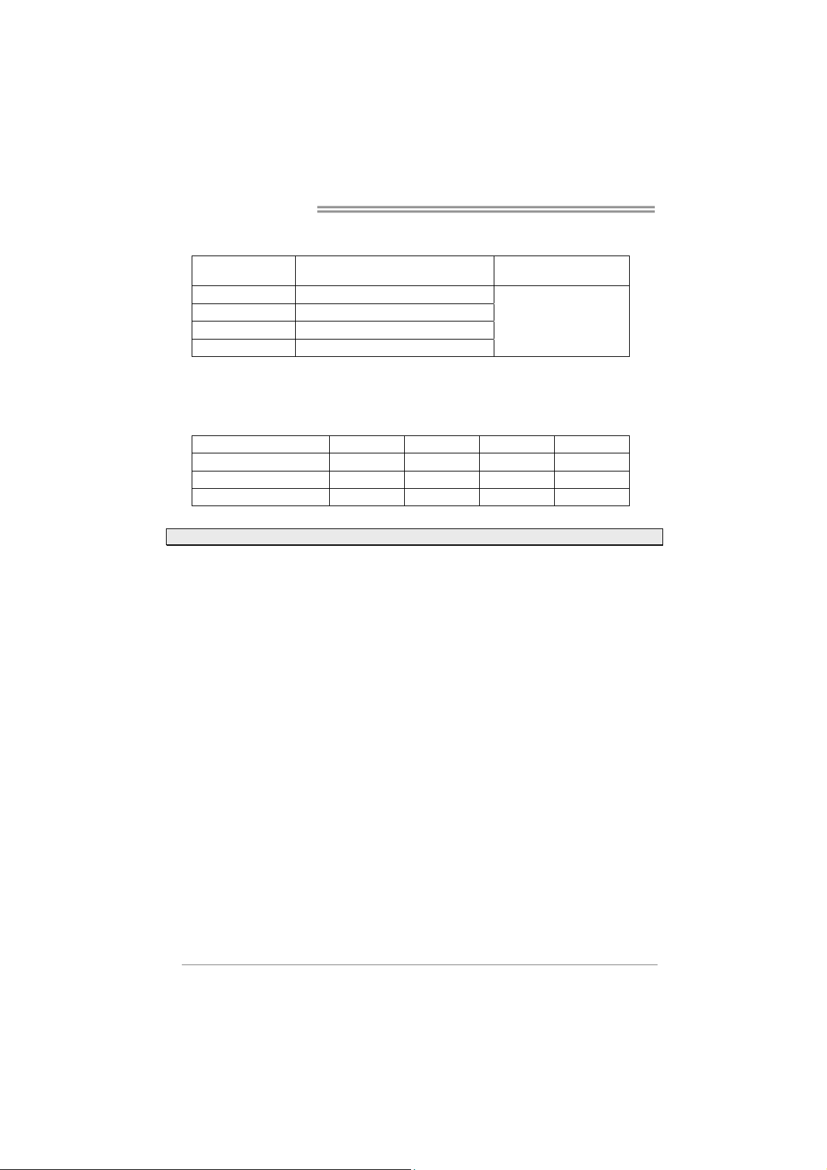
1.3 Motherboard Specifications
Specifications
Socket 1150 for Intel® Core i7 / i5 / i3 / Pentium / Celeron processor
CPU Support
Chipset INTEL® Z87
Memory
Storage
LAN
Audio Codec
USB
Expansion Slots
Rear I/Os
Maximum CPU TDP (Thermal Design Power): 95Watt
* Please refer to
Supports Dual Channel DDR3 1066/ 1333/ 1600/ 1800(OC) / 1866(OC) / 2133(OC) /
2200(OC) / 2400(OC) / 2600(OC) / 2667(OC)
4 x DDR3 DIMM Memory Slot, Max. Supports up to 32 GB Memory
Each DIMM supports non-ECC 512MB/ 1/ 2/ 4/ 8 GB DDR3 module
* Please refer to
INTEL® Z87
6x SATA 6Gb/s Connector
Supports RAID 0,1,10,5, AHCI & SRT
Realtek RTL 8111F
10/ 100/ 1000 Mb/s auto negotiation, Half / Full duplex capability
ALC898
7.1 Channels, High Definition Audio, Biostar Hi-Fi 3D
4x USB 3.0 port (2 on rear I/Os and 2 via internal headers)
8x USB 2.0 port (4 on rear I/Os and 4 via internal headers)
3x PCIe 2.0 x1 Slot
1x PCIe 2.0 x16 Slot (x4)
2x PCIe 3.0 x16 Slot (x8, x8), support AMD CrossFireX™
1x PS/2 Keyboard/ Mouse
1x HDMI Port
1x VGA Port
1x DVI Port
1x LAN port
4x USB 2.0 Port
2x USB 3.0 Port
6x Audio Jack
www.biostar.com.tw for CPU support list.
www.biostar.com.tw for Memory support list.
2
Page 5
Specifications
6x SATA 6.0Gb/s Connector
2x USB 2.0 Header (each header supports 2 USB 2.0 ports)
1x USB 3.0 Header (each header supports 2 USB 3.0 ports)
1x 8-Pin Power Connector
1x 24-Pin Power Connector
Internal I/Os
Form Factor ATX Form Factor, 305 mm x 244 mm
OS Support
1x CPU Fan Connector
4x System Fan Connector
1x Front Panel Header
1x Front Audio Header
1x Clear CMOS Header
1x Consumer IR Header
1x Serial Port Header
1x S/PDIF out Connector
Windows 7/ 8
Biostar reserves the right to add or remove support for any OS with or without notice.
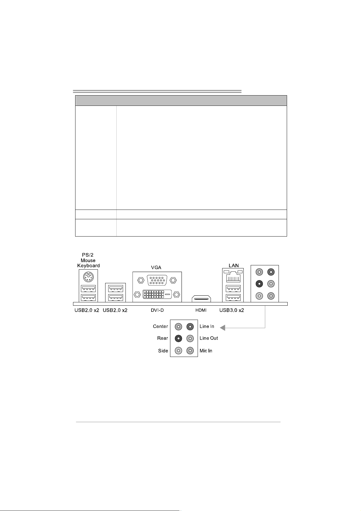
1.4 Rear Panel Connectors
Hi-Fi Z87X 3D
Note1: HDMI, DVI-D & VGA ports only work with an Intel® integrated Graphics Processor.
Note2: Maximum resolution:
HDMI: 4096 x 2160 @24Hz, compliant with HDMI 1.4a
DVI: 1920 x 1200 @60Hz
VGA: 1920 x 1200 @60Hz
Note3: The mainboard supports three onboard display outputs at same time.
3
Page 6
Motherboard Manual
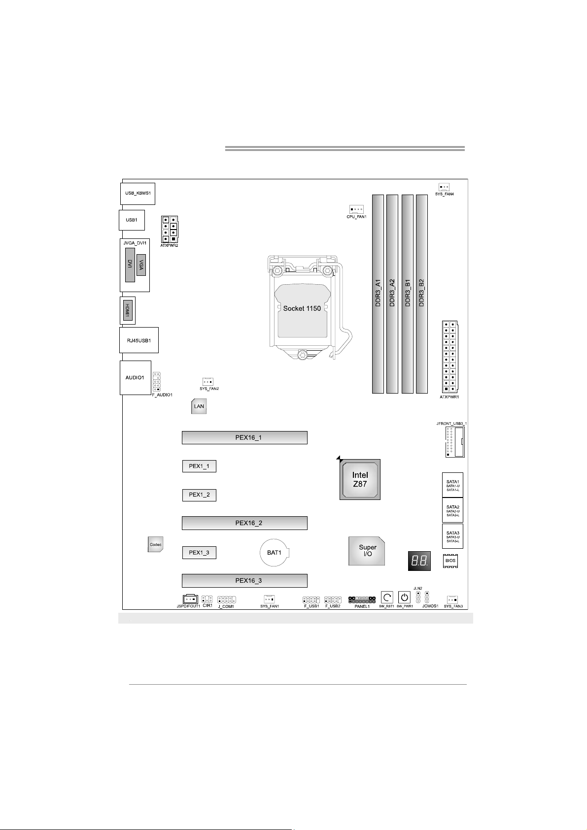
1.5 Motherboard Layout
Distribuidor Consumible IR x1
4
Page 7
Hi-Fi Z87X 3D
CHAPTER 2: HARDWARE INSTALLATION
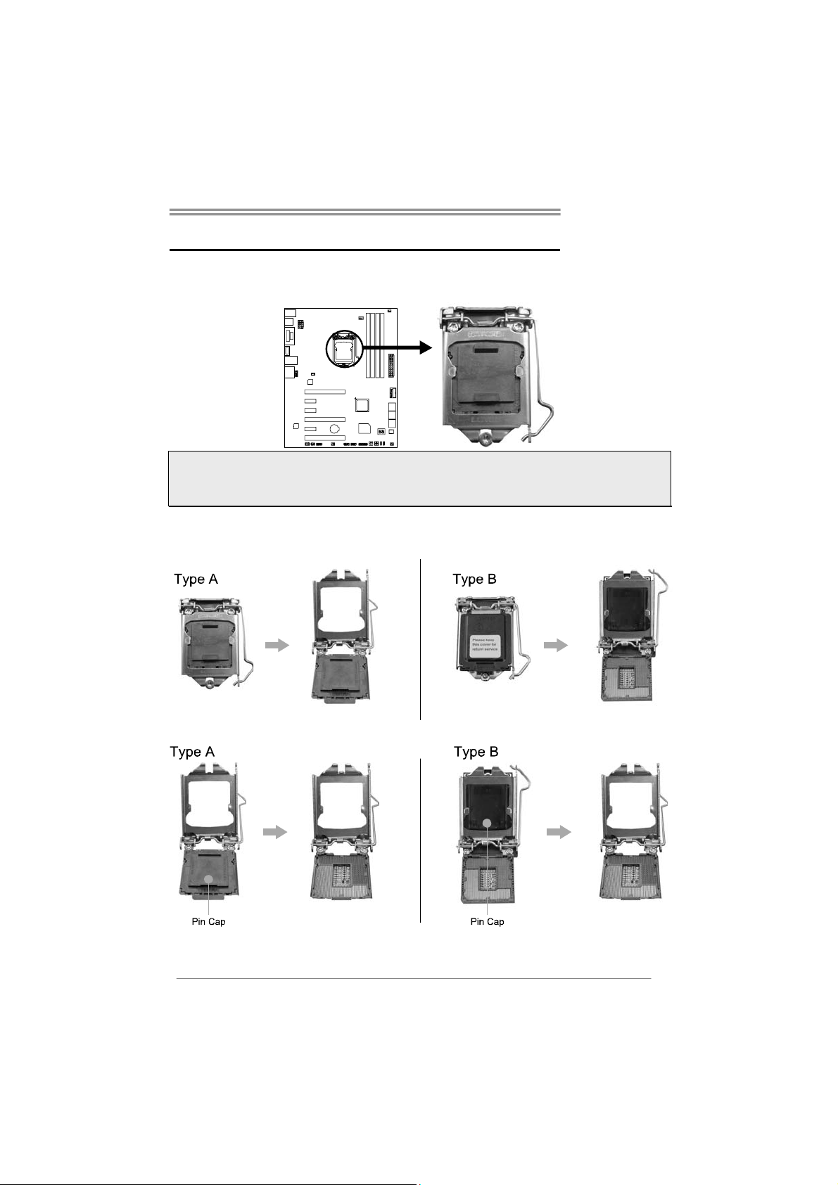
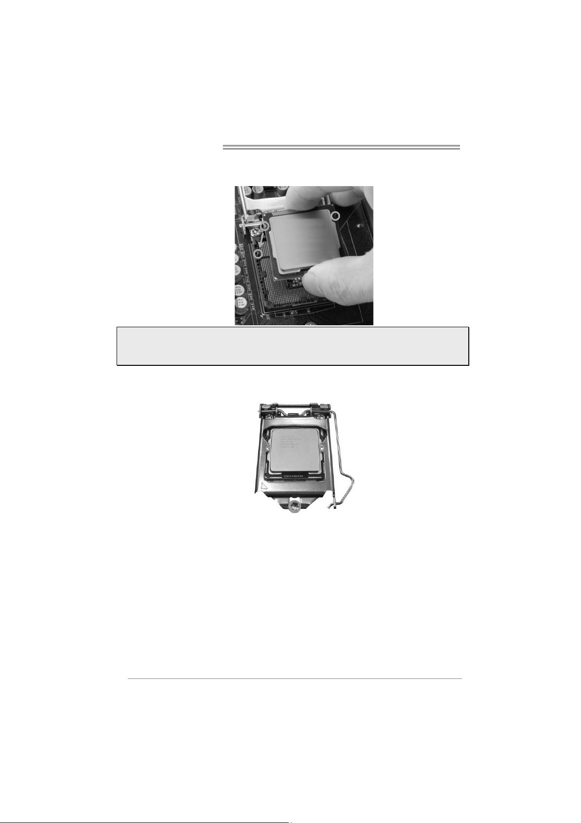
2.1 Install Central Processing Unit (CPU)
Step 1: Locate the CPU socket on the motherboard
Note1: Remove Pin Cap before installation, and make good preservation for future use. When the
CPU is removed, cover the Pin Cap on the empty socket to ensure pin legs won’t be damaged.
Note2: The motherboard might equip with two different types of pin cap. Please refer below
instruction to remove the pin cap.
Step 2: Pull the socket locking lever out from the socket and then raise the lever
up.
Step 3: Remove the Pin Cap.
5
Page 8
Motherboard Manual
Step 4: Hold processor with your thumb and index fingers, oriented as shown.
Align the notches with the socket. Lower the processor straight down
without tilting or sliding the processor in the socket.
Note1: The LGA1155 CPU is not compatible with LGA 1150 socket. Do not install a LGA 1155 CPU
on the LGA 1150 socket.
Note2: The CPU fits only in one correct orientation. Do not force the CPU into the socket to prevent
damaging the CPU.
Step 5: Hold the CPU down firmly, and then lower the lever to locked position to
complete the installation.
6
Page 9
Hi-Fi Z87X 3D
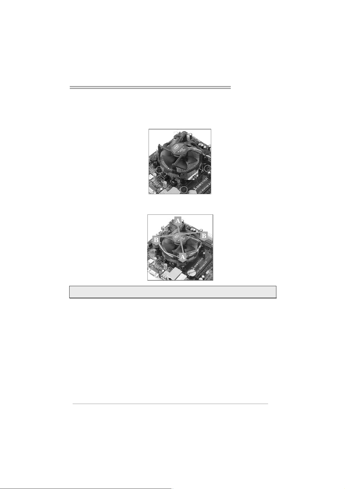
2.2 Install a Heatsink
Step 1: Place the CPU fan assembly on top of the installed CPU and make sure
that the four fasteners match the motherboard holes. Orient the assembly
and make the fan cable is closest to the CPU fan connector.
Step 2: Press down two fasteners at one time in a diagonal sequence to secure
the CPU fan assembly in place. Ensure that all four fasteners are secured.
Note1: Do not forget to connect the CPU fan connector.
Note2: For proper installation, please kindly refer to the installation manual of your CPU heatsink.
7
Page 10
Motherboard Manual
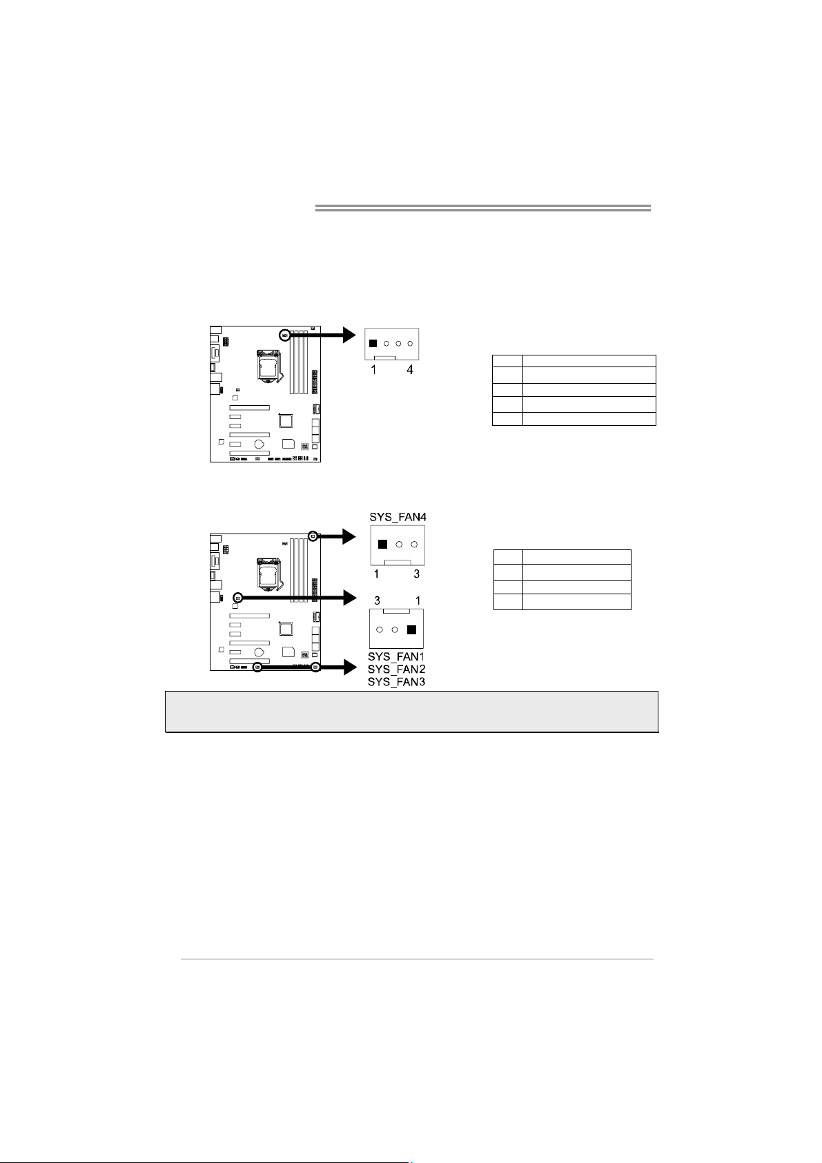
2.3 Connect Cooling Fans
These fan headers support cooling-fans built in the computer. The fan cable and
connector may be different according to the fan manufacturer.
CPU_FAN1: CPU Fan Header
Pin Assignment
1 Ground
2 +12V
3
FAN RPM rate sense
4 Smart Fan Control (By Fan)
SYS_FAN1/2/3/4: System Fan Header
Pin Assignment
1 Ground
2 +12V
3
FAN RPM rate sense
Note: CPU_FAN1, SYS_FAN1/2/3/4 support 4-pin and 3-pin head connectors. When connecting
with wires onto connectors, please note that the red wire is the positive and should be connected to
pin#2, and the black wire is Ground and should be connected to pin#1(GND).
8
Page 11
Hi-Fi Z87X 3D
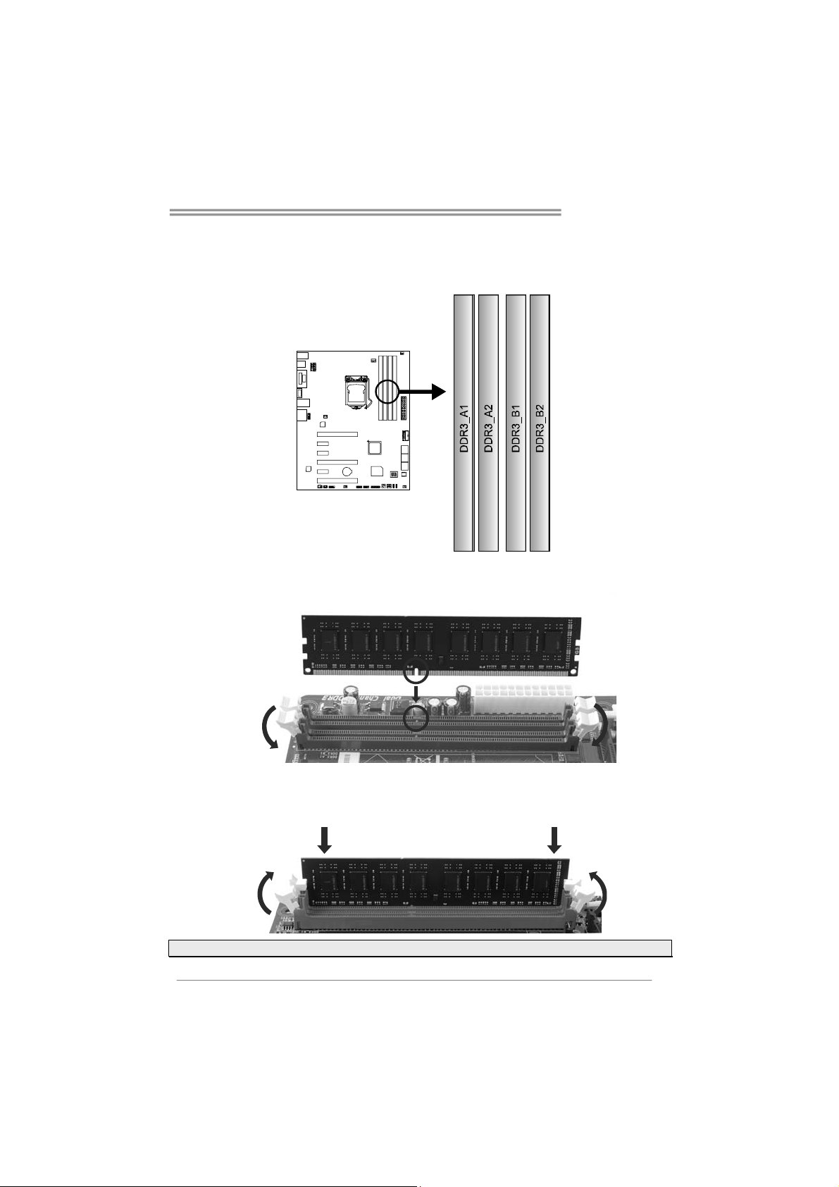
2.4 Install System Memory
DDR3 Modules
Step 1: Unlock a DIMM slot by pressing the retaining clips outward. Align a DIMM
on the slot such that the notch on the DIMM matches the break on the slot.
Step 2: Insert the DIMM vertically and firmly into the slot until the retaining chip snap
back in place and the DIMM is properly seated.
Note: If the DIMM does not go in smoothly, do not force it. Pull it all the way out and try again.
9
Page 12
Motherboard Manual
Memory Capacity
DIMM Socket
Location
DDR3_A1 512MB/1GB/2GB/4GB/8GB
DDR3_A2 512MB/1GB/2GB/4GB/8GB
DDR3_B1 512MB/1GB/2GB/4GB/8GB
DDR3_B2 512MB/1GB/2GB/4GB/8GB
DDR3 Module
Total Memory Size
Max is 32GB.
Dual Channel Memory Installation
Please refer to the following requirements to activate Dual Channel function:
Install memory module of the same density in pairs, shown in the table.
Dual Channel Status DDR3_A1 DDR3_A2 DDR3_B1 DDR3_B2
Enabled O X O X
Enabled X O X O
Enabled O O O O
(O means memory installed, X means memory not installed.)
Note: The DRAM bus width of the memory module must be the same (x8 or x16)
2.5 Expansion Slots
Install an Expansion Card
You can install your expansion card by following steps:
1. Read the related expansion card's instruction document before install the
expansion card into the computer.
2. Remove your computer's chassis cover, screws and slot bracket from the
computer.
3. Place a card in the expansion slot and press down on the card until it is
completely seated in the slot.
4. Secure the card’s metal bracket to the chassis back panel with a screw.
5. Replace your computer's chassis cover.
6. Power on the computer, if necessary, change BIOS settings for the
expansion card.
7. Install related driver for the expansion card.
10
Page 13
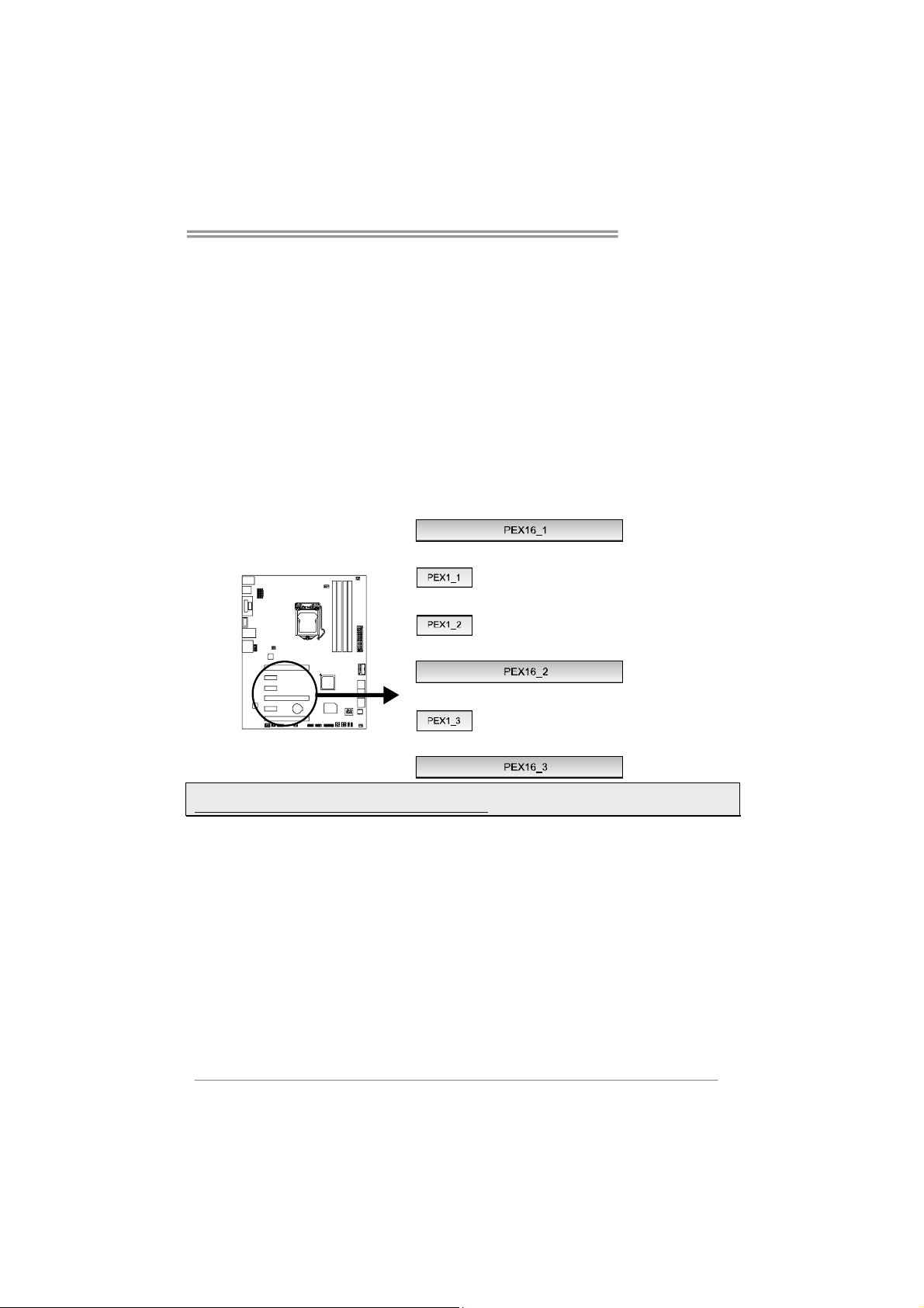
Hi-Fi Z87X 3D
PEX16_1/ PEX16_2: PCI-Express Gen3 x16 (x8 / x8) (AMD
CrossFireX) Slots
- PCI-Express 3.0 compliant.
- Maximum theoretical realized bandwidth of 16GB/s simultaneously per
direction, for an aggregate of 32GB/s totally.
PEX16_3: PCI-Express Gen2 x4 Slot
- PCI-Express 2.0 compliant.
- Maximum theoretical realized bandwidth of 2GB/s simultaneously per
direction, for an aggregate of 4GB/s totally.
PEX1_1/1_2/1_3: PCI-Express Gen2 x1 Slots
- PCI-Express 2.0 compliant.
- Data transfer bandwidth up to 500MB/s per direction; 1GB/s in total
Note: For more details about AMD CrossFireX, please visit below webpage.
http://support.amd.com/us/Pages/AMDSupportHub.aspx
11
Page 14
Motherboard Manual
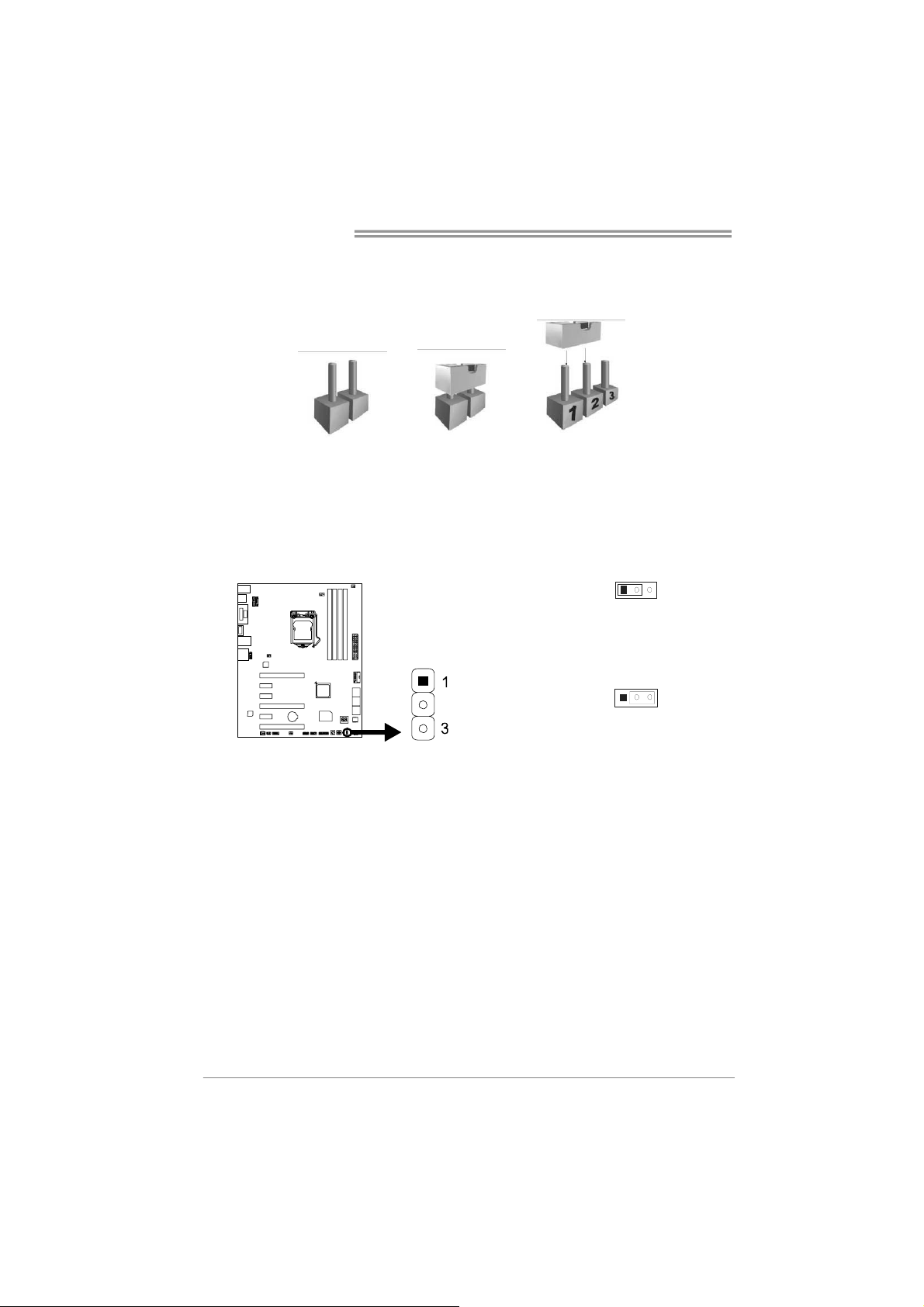
2.6 Jumper Setting
The illustration shows how to set up jumpers. When the jumper cap is placed on
pins, the jumper is “close”, if not, that means the jumper is “open”.
Pin opened Pin closed Pin1-2 closed
JCMOS1: Clear CMOS Jumper
Placing the jumper on pin2-3, it allows user to restore the BIOS safe setting and
the CMOS data. Please carefully follow the procedures to avoid damaging the
motherboard.
Pin 1-2 Close:
Normal Operation (default).
31
12
Pin 2-3 Close:
Clear CMOS data.
※ Clear CMOS Procedures:
1. Remove AC power line.
2. Set the jumper to “Pin 2-3 close”.
3. Wait for five seconds.
4. Set the jumper to “Pin 1-2 close”.
5. Power on the AC.
6. Load Optimal Defaults and save settings in CMOS.
31
Page 15
Hi-Fi Z87X 3D
2.7 Headers & Connectors
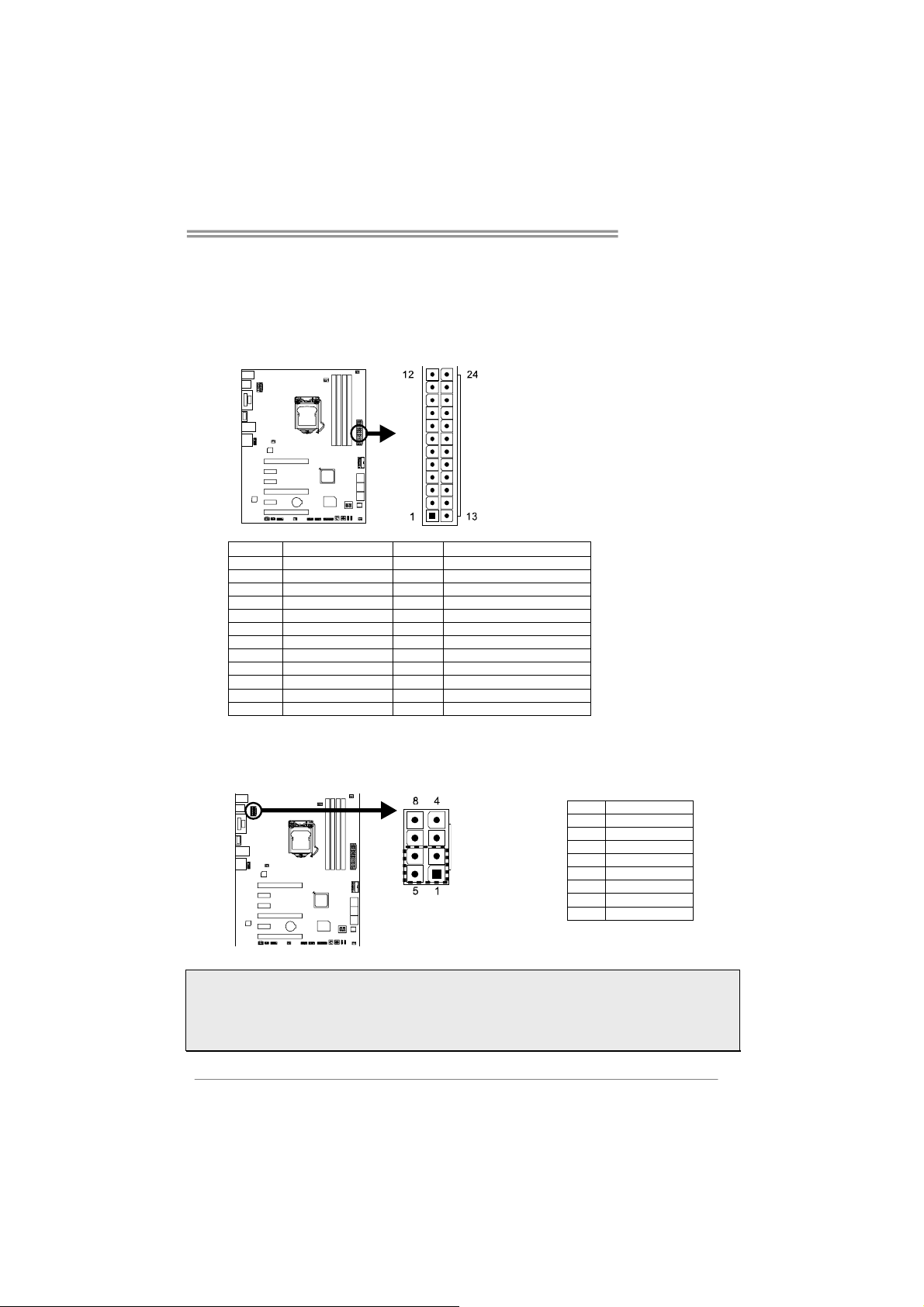
ATXPWR1: ATX Power Source Connector
This connector allows user to connect an ATX 24-pin power supply. Make sure to
find the proper orientation before plugging the connector.
Pin Assignment Pin Assignment
13 +3.3V 1 +3.3V
14 -12V 2 +3.3V
15 Ground 3 Ground
16 PS_ON 4 +5V
17 Ground 5 Ground
18 Ground 6 +5V
19 Ground 7 Ground
20 NC 8 PW_OK
21 +5V 9 Standby Voltage+5V
22 +5V 10 +12V
23 +5V 11 +12V
24 Ground 12 +3.3V
ATXPWR2: ATX Power Source Connector
The connector provides +12V to the CPU power circuit. If the CPU power plug is
4-pin, please plug it into Pin 1-2-5-6 of ATXPWR2.
Pin Assignment
1 +12V
2 +12V
3 +12V
4 +12V
5 Ground
6 Ground
7 Ground
8 Ground
Note1: Before you power on the system, please make sure that both ATXPWR1 and ATXPWR2
connectors have been plugged-in.
Note2: Insufficient power supplied to the system may result in instability or the peripherals not
functioning properly. Use of a PSU with a higher power output is recommended when configuring a
system with more power-consuming devices.
13
Page 16
Motherboard Manual
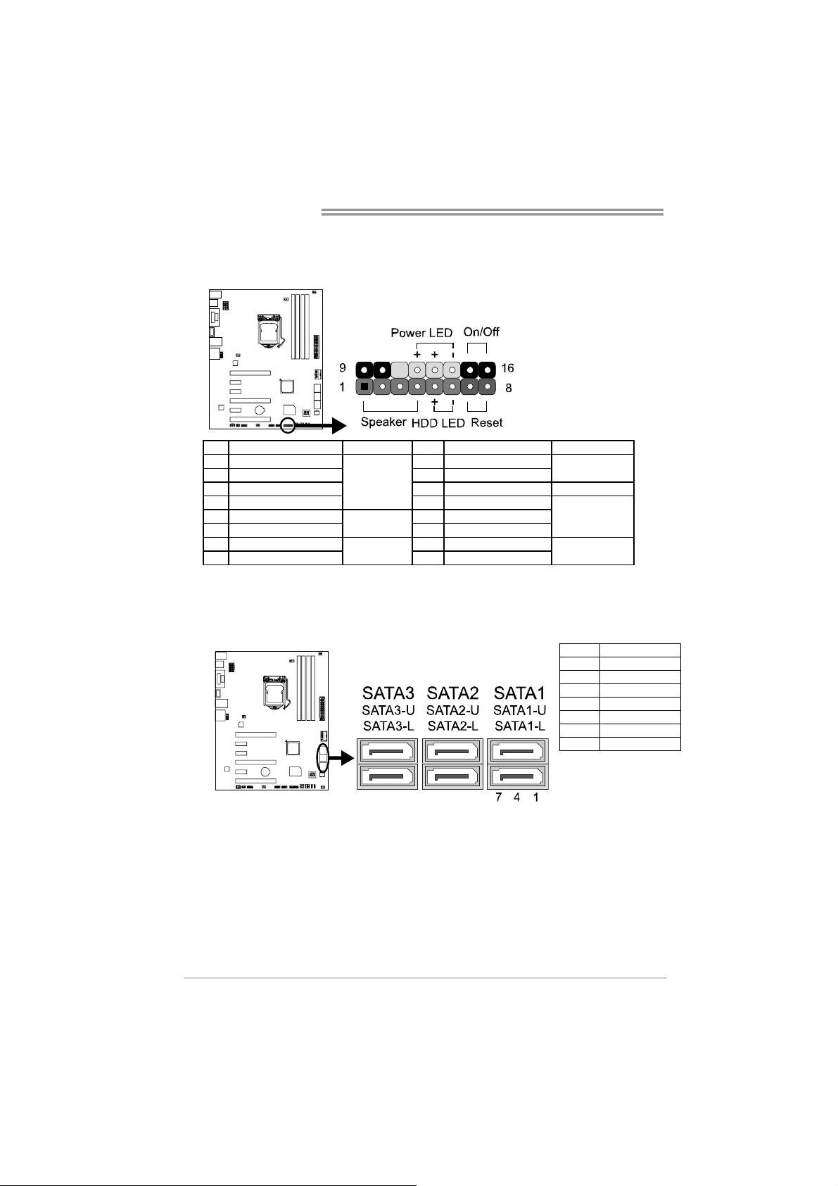
PANEL1: Front Panel Header
This 16-pin header includes Power-on, Reset, HDD LED, Power LED, and speaker
connection. It allows user to connect the PC case’s front panel switch functions.
Pin Assignment Function Pin Assignment Function
1 +5V 9 N/A
2 N/A 10 N/A
3 N/A 11 N/A N/A
4 Speaker
5 HDD LED (+) 13 Power LED (+)
6 HDD LED (-)
7 Ground 15 Power button
8 Reset control
Speaker
Connector
Hard drive
LED
Reset button
12 Power LED (+)
14 Power LED (-)
16 Ground
N/A
Power LED
Power-on button
SATA1~SATA3: Serial ATA 6.0 Gb/s Connectors
These connectors connect to SATA hard disk drives via SATA cables.
Pin Assignment
1 Ground
2 TX+
3 TX4 Ground
5 RX6 RX+
7 Ground
14
Page 17

Hi-Fi Z87X 3D
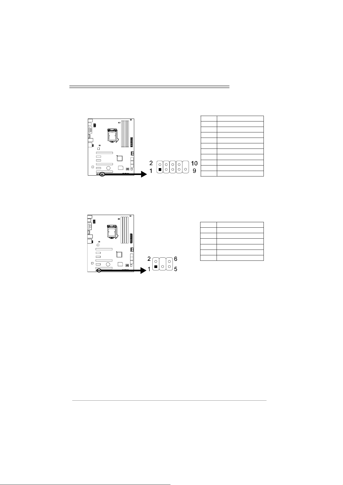
JFRONT_USB3_1: Header for USB 3.0 Ports at Front Panel
This header allows user to add additional USB ports on the PC front panel, and
also can be connected with a wide range of external peripherals.
Pin Assignment Pin Assignment
1 VBUS0 11 D2+
2 SSRX1- 12 D23 SSRX1+ 13 Ground
4 Ground 14 SSTX2+
5 SSTX1- 15 SSTX26 SSTX1+ 16 Ground
7 Ground 17 SSRX2+
8 D1- 18 SSRX29 D1+ 19 VBUS1
10 ID 20 Key
F_USB1/2: Header for USB 2.0 Ports at Front Panel
This header allows user to add additional USB ports on the PC front panel, and
also can be connected with a wide range of external peripherals.
Pin Assignment
1 +5V (fused)
2 +5V (fused)
3 USB4 USB5 USB+
6 USB+
7 Ground
8 Ground
9 NC
10 Key
15
Page 18
Motherboard Manual
F_AUDIO1: Front Panel Audio Header
This header allows user to connect the chassis-mount front panel audio I/O which
supports HD and AC’97 audio standards.
HD Audio AC’97
Pin Assignment Pin Assignment
1 Mic Left in 1 Mic In
2 Ground 2 Ground
3 Mic Right in 3 Mic Power
4 GPIO 4 Audio Power
5 Right line in 5 RT Line Out
6 Jack Sense 6 RT Line Out
7 Front Sense 7 Reserved
8 Key 8 Key
9 Left line in 9 LFT Line Out
10 Jack Sense 10 LFT Line Out
Note1: It is recommended that you connect a high-definition front panel audio module to this
connector to avail of the motherboard's high definition audio capability.
Note2: Please try to disable the "Front Panel Jack Detection" if you want to use an AC'97 front
audio output cable. The function can be found via O.S. Audio Utility.
JSPDIFOUT1: Digital Audio-out Connector
The connector is for connecting the S/PDIF output bracket.
16
Pin Assignment
1 +5V
2 SPDIF_OUT
3 Ground
Page 19
Hi-Fi Z87X 3D
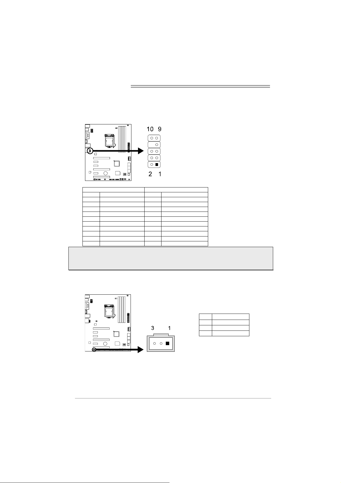
J_COM1: Serial Port Header
The motherboard has a serial port header for connecting RS-232 Port.
Pin Assignment
1 Carrier detect
2 Received data
3 Transmitted data
4 Data terminal ready
5 Signal ground
6 Data set ready
7 Request to send
8 Clear to send
9 Ring indicator
10 NC
CIR1: Consumer IR Header
This header is for infrared remote control and communication.
Pin Assignment
1 IrDA serial input
2 Ground
3 Ground
4 Key
5 IrDA serial output
6 IR Power
17
Page 20
Motherboard Manual
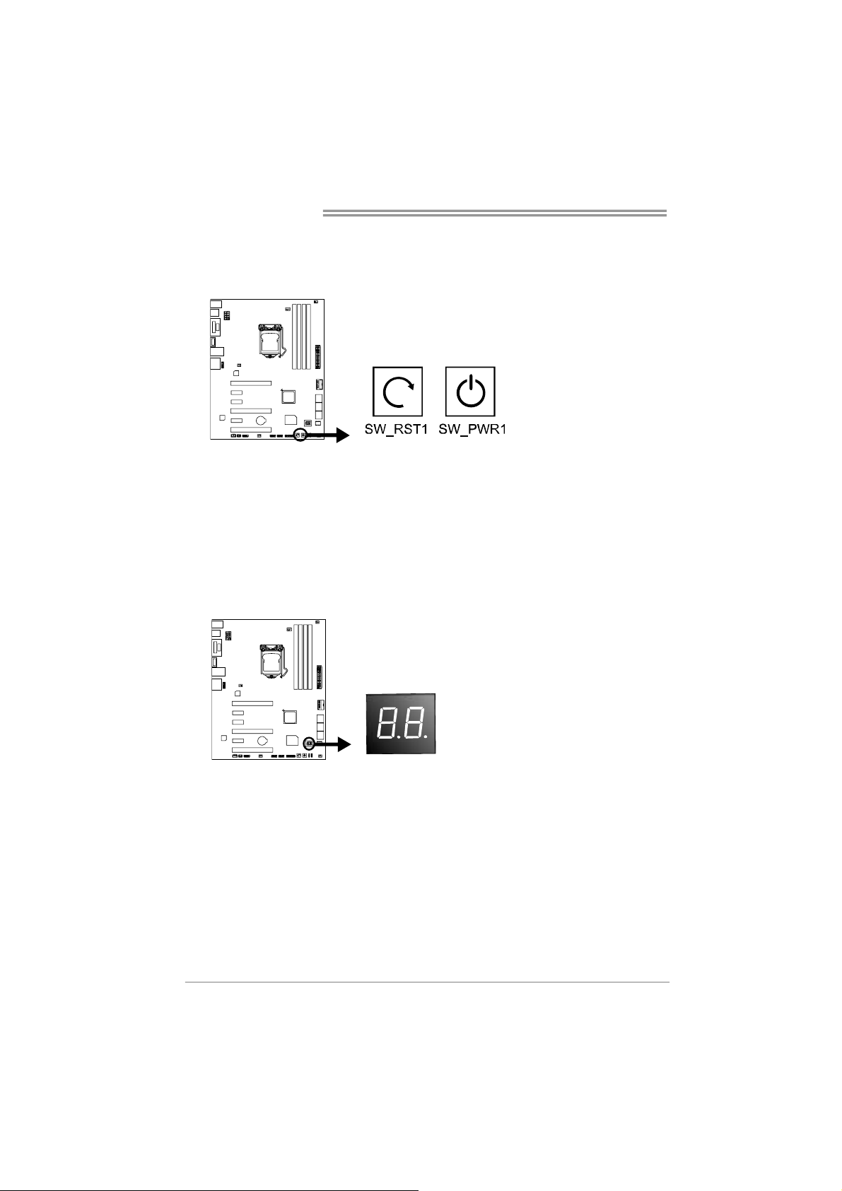
2.8 Smart Switches & Indicators
On-Board Buttons
SW_PWR1:
This is an on-board Power Switch button.
SW_RST1:
This is an on-board Reset button.
BIOS POST Code/CPU Temperature Indicator
This indicator will show POST code while booting. After the booting sequence, it
will show current CPU temperature in Celsius. Please refer to Chapter 4.3 for all
the BIOS POST codes.
18
Page 21

Hi-Fi Z87X 3D
CHAPTER 3: UEFI BIOS & SOFTWARE
3.1 UEFI BIOS Setup
z The BIOS Setup program can be used to view and change the BIOS
settings for the computer. The BIOS Setup program is accessed by pressing
the <DEL> key after the Power-On Self-Test (POST) memory test begins
and before the operating system boot begins.
z For further information of setting up the UEFI BIOS, please refer to the UEFI
BIOS Manual in the Setup DVD.
3.2 BIOS Update
The BIOS can be updated using either of the following utilities:
z BIOSTAR BIOS Flasher: Using this utility, the BIOS can be updated from a
file on a hard disk, a USB drive (a flash drive or a USB hard drive), or a
CD-ROM.
z BIOSTAR BIOS Update Utility: It enables automated updating while in the
Windows environment. Using this utility, the BIOS can be updated from a file
on a hard disk, a USB drive (a flash drive or a USB hard drive), or a
CD-ROM, or from the file location on the Web.
BIOSTAR BIOS Flasher
Note1: This utility only allows storage device with FAT32/16 format and single partition.
Note2: Shutting down or resetting the system while updating the BIOS will lead to system boot
failure.
Updating BIOS with BIOSTAR BIOS Flasher
1. Go to the website to download the latest BIOS file for the motherboard.
2. Then, copy and save the BIOS file into a USB flash (pen) drive.
3. Insert the USB pen drive that contains the BIOS file to the USB port.
4. Power on or reset the computer and then press <F12> during the POST process.
5. After entering the POST screen,
the BIOS-FLASHER utility pops
out. Choose [fs0] to search for the
BIOS file.
19
Page 22

Motherboard Manual
6. Select the proper BIOS file, and a
message asking if you are sure to
flash the BIOS file. Click Yes to
start updating BIOS.
7. A dialog pops out after BIOS flash
is completed, asking you to restart
the system. Press the [Y] key to
restart system.
8. While the system boots up and the full screen logo shows up, press <DEL> key to
enter BIOS setup.
After entering the BIOS setup, please go to the Save & Exit, using the Restore
Defaults function to load Optimized Defaults, and select Save Changes and
Reset to restart the computer. Then, the BIOS Update is completed.
BIOS Update Utility (through the Internet)
1. Installing BIOS Update Utility from the DVD Driver.
2. Please make sure the system is connected to the internet before using this
function.
3. Launch BIOS Update Utility and
click the Online Update button on
the main screen.
20
Page 23

Hi-Fi Z87X 3D
4. An open dialog will show up to
request your agreement to start the
BIOS update. Click Yes to start the
online update procedure.
5. If there is a new BIOS version, the
utility will ask you to download it.
Click Yes to proceed.
6. After the download is completed,
you will be asked to program
(update) the BIOS or not. Click Yes
to proceed.
7. After the updating process is
finished, you will be asked you to
reboot the system. Click OK to
reboot.
8. While the system boots up and the full screen logo shows up, press <DEL> key
to enter BIOS setup.
After entering the BIOS setup, please go to the Save & Exit, using the Restore
Defaults function to load Optimized Defaults, and select Save Changes and
Reset to restart the computer. Then, the BIOS Update is completed.
BIOS Update Utility (through a BIOS file)
1. Installing BIOS Update Utility from the DVD Driver.
2. Download the proper BIOS from http://www.biostar.com.tw/
3. Launch BIOS Update Utility and
click the Update BIOS button on
the main screen.
21
Page 24

Motherboard Manual
4. A warning message will show up
to request your agreement to start
the BIOS update. Click OK to start
the update procedure.
5. Choose the location for your BIOS
file in the system. Please select
the proper BIOS file, and then
click on Open. It will take several
minutes, please be patient.
6. After the BIOS Update process is
finished, click on OK to reboot the
system.
7. While the system boots up and the full screen logo shows up, press <DEL> key
to enter BIOS setup.
After entering the BIOS setup, please go to the Save & Exit, using the Restore
Defaults function to load Optimized Defaults, and select Save Changes and
Reset to restart the computer. Then, the BIOS Update is completed.
Backup BIOS
Click the Backup BIOS button on
the main screen for the backup of
BIOS, and select a proper location
for your backup BIOS file in the
system, and click Save.
22
Page 25

Hi-Fi Z87X 3D
3.3 Software
Installing Software
1. Insert the Setup DVD to the optical drive. The driver installation program would
appear if the Auto-run function has been enabled.
2. Select Software Installation, and then click on the respective software title.
3. Follow the on-screen instructions to complete the installation.
Launching Software
After the installation process is completed, you will see the software icon showing on
the desktop. Double-click the icon to launch it.
Note1: All the information and content about following software are subject to be changed without
notice. For better performance, the software is being continuously updated.
Note2: The information and pictures described below are for your reference only. The actual
information and settings on board may be slightly different from this manual.
TOverclocker
TOverclocker presents a simple Windows-based system performance enhancement
and manageability utility. It features several powerful and easy to use tools such as
Overclocking for enhancing system performance, also for special enhancement on
CPU and Memory. Smart-Fan management and PC health are for monitoring system
status. This utility also allows you to make overclocking profiles saving unlimitedly, and
pre-set OC modes are for easy OC. (The screenshots below are for reference only)
The CPU tab provides information on the CPU and motherboard.
The Memory tab provides information on the memory module(s).
You can select memory module on a specific slot to see its information.
23
Page 26

Motherboard Manual
The OC Tweaker tab allows you to save or load the OC setting profiles,
change system frequency and voltage settings.
The HW Monitor tab allows you to monitor hardware voltage, fan
speed, and temperature. You can also set CPU Smart Fan function in this tab.
Note1: Not all types of CPU perform above overclock setting ideally; the difference will be based on
the selected CPU model.
Note2: Overclock is an optional process, but not a “must-do” process; it is not recommended for
inexperienced users. Therefore, we will not be responsible for any hardware damage which may be
caused by overclocking. We also would not guarantee any overclocking performance.
Note3: Press TOVERCLOCKER logo, it will display information about manufacturer and software
version. You can update latest version by clicking the “Live Update” button.
24
Page 27

Hi-Fi Z87X 3D
BIOScreen Utility
This utility allows you to personalize your boot logo easily. You can choose BMP as
your boot logo so as to customize your computer.
Please follow the step-by-step instructions below to update boot logo:
z Load Image:Choose the picture as the boot logo.
z Transform:Transform the picture for BIOS and preview the result.
z Update Bios:Write the picture to BIOS Memory to complete the update.
25
Page 28

Motherboard Manual
eHot-Line
eHot-Line is a convenient utility that helps you to contact with our Tech-Support system.
This utility will collect the system information which is useful for analyzing the problem
you may have encountered, and then send these information to our tech-support
department to help you fix the problem.
Note: Before you use this utility, please set Outlook Express as your default e-mail client
application program.
represents important
*
in forma tion t hat you
must provide. Without
this information, you may
not be able to send out
the mail.
This block will show
the information which
wou ld be co llec ted in
the mail.
Send the mail out.
Describe condition
*
of your system.
Save these information to a .txt file
Exit this dialog.
Select your area or
*
the area close to you.
Pro vide t he e-mail
address that you would
like to send the copy to.
Pro vide t he name of
*
the memory module
manufactur er.
Pro vide t he name of
the power supply
manufacturer and the
model no.
After filling up this information, click
“Send” to send the mail out. A
warning dialog would appear asking
for your confirmation; click “Send” to
confirm or “Do Not Send” to cancel.
If you want to save this information to
a .txt file, click “Save As…” and then
you will see a saving dialog appears
asking you to enter file name.
26
Page 29

Hi-Fi Z87X 3D
Enter the file name and then click
“Save”. Your system information will be
saved to a .txt file.
Open the saved .txt file, you will see
your system information including
motherboard/BIOS/CPU/video/
device/OS information. This
information is also concluded in the
sent mail.
Note1: We will not share customer’s data with any other third parties, so please feel free to provide
your system information while using eHot-Line service.
Note2: If you are not using Outlook Express as your default e-mail client application, you may need
to save the system information to a .txt file and send the file to our tech support with other e-mail
application. Go to the following website http://www.biostar.com.tw/app/en/about/contact.php for
getting our contact information.
27
Page 30

Motherboard Manual
Smart EAR 3D
Hi-Fi 3D Audio Requirements:
1. A chassis with front audio output jacks
2. An earphone or a headphone
3. Speakers
4. Windows 7 or Windows 8 operation system
Installation Guide:
1. Make sure the front audio cable of the chassis connected to the front audio
header of the motherboard properly.
2. Install the Smart Ear 3D Utility from the driver DVD.
3. Connect the earphone or headphone to the front audio jack of the chassis for
Smart Gain and 3D Sound Field functions.
4. Connect the speakers to center, rear, side and line out ports of rear panel for
Smart PREAMP function.
Note: If you want to use an AC'97 front audio output cable, please disable the "Front Panel Jack
Detection" setting. This setting can be found via O.S. Audio Utility.
28
Page 31

Smart EAR 3D Utility:
Hi-Fi Z87X 3D
1. Rear Panel Audio Output Indicator: It displays a blue light when the audio
output is from rear panel ports.
2. 3D Sound Field Button: There are six sound environment options for achieving
realistic listening experience. It displays a blue light when the 3D Sound Field is
enabled.
3. Smart PREAMP Button: Click this switch to turn on or off the Smart PREAMP
function.
4. Mute Button: To disable system sound
5. Control Button: It allows you to set utility preference.
6. Volume Control Knob: The volume can be finely adjusted by turning the knob
either clockwise or anti-clockwise to increase or decrease system volume
accordingly.
7. Headphone Hi/Mid/Low Gain Switch: It allows you to select headphone gain
settings or you can let the software auto adjust headphone gain setting
appropriate for your headphones. The Smart Gain function will be enabled when
the 3D Sound Field Button is turned on.
8. Front Panel Audio Output Indicator: It displays a blue light when the audio
output is from front panel port.
9. Exit Button: Exit the application
10. Minimize Button: Minimize the application window to the taskbar
11. Information Button: Get information of the application
12. Smart PREAMP or Smart Gain ON/OFF Indicator: When the Rear Panel
Audio Output Indicator is lit, it shows Smart PREAMP on/off status. When the
Front Panel Audio Output Indicator is lit, it shows Smart Gain on/off status.
Note1: The 3D Sound Field function is only for front panel audio output.
Note2: The Smart PREAMP function is only for rear panel audio output.
Note3: When both rear and front panels are connected with audio devices, the default audio output
is from front panel.
29
Page 32

Motherboard Manual
Multi Channels Calibration (MCC)
Multi Channels Calibration (MCC) can transform any room into the ideal listening
environment. With Multi Channels Calibration (MCC), audio performance is
automatically calibrated according to the dimensions of your room.
Take a note of following precautions before you start the calibration.
1. Do not connect or disconnect the speaker setup microphone and speakers during the calibration.
2. Do not stand between the speakers and microphone, and avoid obstacles blocking the path
between speakers and microphone.
3. Turn off all media players and do not adjust any audio settings (ex. volume or mute) in your
operating system.
4. MCC software is only supported by Windows 7/8 and BIOSTAR Hi-Fi series motherboards.
z Status Panel: Show the information of speakers and listening positions.
z Midnight Mode: Turn on this function will let you enjoy a movie quietly without
compromising sound qualities, surround effects and dialogue clarity.
z Calibration Button: Start or stop the calibration.
z Channel Output Buttons: Select the channel output (2/ 4/ 5.1/ 7.1-channel)
z Listening Position Buttons: It allows you setup five listening positions.
z Speaker Volume: Show each speaker’s volume.
z Information Button: Get information of the application.
z Minimize Button: Minimize the application window to the taskbar.
z Exit Button: Exit the application.
30
Page 33

Hi-Fi Z87X 3D
Start the Calibration:
Step 1:
Install and launch Multi Channels Calibration software
Step 2:
Arrange and connect the speakers in your room.
Step 3:
Select the channel output (2/ 4/ 5.1/ 7.1-channel) for the speak configuration.
Step 4:
Place the speaker setup microphone at ear height of a seated listener in your room
and connection it to Mic In jack.
Note: To setup 5.1-channel for a motherboard with 3 audio jacks, please connect the speaker
setup microphone to front panel Mic-In.
Step 5:
Select your preferred listening position and click the “Listening Position Button”.
Step 6:
Click the “Calibration Button”. You can see a notice window then click “Next” to start
the calibration. The test tone will be played through each speakers and it will take
2-3 minutes to process the calibration. Please make the room as quiet as possible at
the meantime.
Step 7:
After completing calibration, you will see a finish window then click “OK” to exit this
calibration.
Audio Ports:
For the definition of each audio port, please refer to the table below:
The 2/ 4/ 5.1-channel configuration for 3 audio jacks
Port 2-channel 4-channel 5.1 channel
Blue Line In Rear Speaker Out Rear Speaker Out
Green Line Out Front Speaker Out Front Speaker Out
Pink Mic In Mic In Center/Subwoofer Out
The 2/ 4/ 5.1/ 7.1-channel configuration for 6 audio jacks
Port 2-channel 4-channel 5.1 channel 7.1 channel
Blue Line In Line In Line In Line In
Green Line Out Front Speaker Out Front Speaker Out Front Speaker Out
Pink Mic In Mic In Mic In Mic In
Orange -- -- Center/Subwoofer Out Center/Subwoofer Out
Black N/A Rear Speaker Out Rear Speaker Out Rear Speaker Out
Grey -- -- -- Side Speaker Out
Note: Green, Orange, Black and Grey jacks are only for audio outputs.
31
Page 34

Motherboard Manual
Smart Connect Technology
Intel® Smart Connect Technology is designed to update programs by periodically
waking your computer from sleep/standby mode for a short time. This function works
with applications that automatically get their data from the Internet.
System Requirement:
z Intel Smart Connect Technology enabled in BIOS Setup
z Set the “ACPI Sleep State” to S3 in BIOS Setup.
z Windows 7 and Windows 8
z Normal internet connection
Configuring Intel Smart Connect Technology
Step 1: After installing the operating system and motherboard drivers, install the Intel
Smart Connect Technology application. Restart your computer when completed.
Step 2: Click on start menu and input "regedit" in the search bar. Press enter to open
the registry editor. Look for the following directory in the registry editor:
Computer\HKEY_LOCAL_MACHINE\SOFTWARE\Intel\Intel Smart Connect Technology
Right-click on Intel Smart Connect Technology and select New > Key. Type “OEM”.
Note: Intel Smart Connect Technology is for S3 mode only. During the updating process, the
monitor will not light up and no sound will be output from the speaker.
Step 3: As shown in the screenshot below, right-click on OEM, select New >
Multi-String Value, and type “WhiteList”. Double-click WhiteList and type the
application name to be added in Edit Multi-String. For example, to add Microsoft Live
Mail, type “wlmail.exe”. Restart your computer when completed.
Step 4: After completing the steps above, go to Start\All Programs\Intel and launch
Intel(R) Smart Connect Technology.
32
Page 35

Hi-Fi Z87X 3D
Basic and advanced settings
Basic Tab
Update Frequency slider: This slider bar sets the amount of time the feature waits to wake
your computer and update your applications. Move the slider in the user interface to change
the frequency. The slider bar can be set to wake and update your computer from every 15 to
60 minutes. The longer the time between updates the less power the feature consumes.
Reset All to Defaults button: This button is designed to reset Intel® Smart Connect
Technology back to the original factory setting for wake frequency.
Advanced Tab
Extended Power Savings: You can set a time for Intel Smart Connect Technology to work in
Extended Power Savings mode. This night time mode updates your computer every two
hours, saving power for the times you are not using your computer.
33
Page 36

Motherboard Manual
Rapid Start Technology
Intel® Rapid Start technology enables your system to get up and running faster from
even the deepest sleep, saving time and power consumption. Feel secure knowing that
your system will still resume to working conditions in the event of unexpected power
loss while in sleep mode.
System Requirement:
z An Intel® SATA SSD (SATA Gen2 or Gen3. Preferably Gen3, and 80 GB or
larger)
z Windows 7 and Windows 8
Note1: Please visit below webpage for more details about operating systems supporting
http://www.intel.com/p/en_US/support
Note2: The Rapid Start Technology is NOT supported by H81 chipset.
Installing Intel® SBA:
Step 1: BIOS Setting
1-1 Go to [Advanced Menu] > [ACPI Settings], and set [ACPI Sleep State] to S3
(Suspend to RAM)
1-2 Go to [Advanced Menu] > [SATA Configuration], and set [SATA Mode
Selection] to AHCI
1-3 Go to [Advanced Menu] and set [Intel(R) Rapid Start Technology] to Enabled
1-4 Save your changes, and then exit the BIOS Setup.
Step 2: Operating System Installation
Step 3: Installing Intel® Rapid Start Application
3-1 Insert the setup Driver DVD into your optical drive. Click “Intel Rapid Start
Technology” to launch the program.
3-2 Below window will pop-out, then click “Create Disk” to star disk partition. After
disk partition finished, please click “OK” then system will reboot automatically.
34
Page 37

Hi-Fi Z87X 3D
3-3 After rebooting, the system will setup Intel® Rapid Start Technology
automatically. We recommend you restart the system after this installation is
complete,
Step 4: Configuring Intel® Rapid Start Application
Launch the Intel® Rapid Start Technology Manager application from [Start] > [All
Programs] > [Intel] or click the icon in the notification area.
35
Page 38

Motherboard Manual
Lucid VIRTU MVP 2.0
Lucid VIRTU MVP 2.0 is designed for the platforms with one integrated and one
discrete GPU. VIRTU MVP 2.0 dynamically assigns tasks to best available graphics
resource based on power, performance and features.
System Requirements:
z CPU: Any CPU with integrated graphics support
z Chipset: Any chipset with integrated graphics output
z Discrete GPU: Any Nvidia/ AMD GPU with DX9/ DX10/ DX11 support
z Memory Size: 2GB
z Operating System: Windows 7 and Windows 8
z Hard Disk Space: 20MB
BIOS Setting:
Please try to set Onboard VGA (IGD) as first display if you want to use “i-mode”.
i-Mode:
i-Mode provides user with near zero performance overhead on 3D graphics games,
Virtual VSync and Hyperformance features, integrated GPU special features and power
saving options when no 3D gaming is used.
To use Lucid VIRTU Universal MVP solution in i-Mode, display must be always
connected to motherboard video output.
Note: Display can be also connected to VGA or HDMI output instead of DVI output.
d-Mode:
d-Mode is provided for demanding 3D gamers to achieve uncompromised 3D
performance of discrete GPU installed in the system, along with Virtual VSync and
Hyperformance quality/performance improvement features. In this mode, Virtu
Universal MVP allows user to utilize integrated GPU special features such as
trascoding, while display is connected to discrete GPU.
Note1: In most cases the differences of 3D performance between i-Mode and d-Mode are
unnoticeable to the user, so it is recommended to use i-mode to save power.
Note2: To use Lucid VIRTU Universal MVP 2.0 solution in d-Mode, display must be connected to
discrete GPU installed in the system.
36
Page 39

Software Installation & Operation:
1. GPU drivers must be installed prior to
Lucid VIRTU MVP 2.0 installation.
2. The VIRTU MVP 2.0 Setup Wizard
window is displayed.
3. Click Next and follow the
on-screen instructions to complete
the software installation.
4. When the installation is complete,
“Completing the VIRTU MVP 2.0
Setup Wizard” window is displayed.
5. Select "Yes, restart the computer
now" option and click Finish. The
VIRTU MVP 2.0 installation process is
completed.
Hi-Fi Z87X 3D
6. Once installed, Virtu MVP logo shows
on system tray (the right bottom
corner of the screen). Mouse right
click at the icon, will display the
following screen.
7. When opening the VIRTU MVP 2.0
control panel (either from the start
menu or from the system tray icon),
the following window is displayed.
8. By pressing
button VIRTU MVP
2.0 solution is enabled.
Note: For more detail settings about Virtu MVP 2.0, please refer to the Virtu MVP 2.0 user’s manual
in the Setup DVD.
37
Page 40

Motherboard Manual
Green Power II Utility
BIOSTAR G.P.U II (Green Power Utility) is a new function. The utility enhances energy
efficiency by disabling extra phases while CPU is on light loading; it features 4+1 power
phases, current power saving, and total power saving. This tool integrates a friendly
GUI to monitor your CPU Usage, CPU Watt, and CPU Temperature. Moreover, it
optimizes power saving and best power efficiency on your system. (The illustration
below is for reference only)
Typical Mode
Display manufacturer &
software version information
Performance
Mode
Medium Mode
Maxi-Energy Mode
Auto Phase Mode
Reset Time &
Consumption
Display CPU
information
G.P.U Mode Setting:
This utility provides five modes, upon your requirements, to improve system
performance or to save power consumption.
Note: Even if the modes saving more power consumption are chosen, the system still can keep
excellent performance.
z Auto Phase Mode: System switches the mode automatically according to
current system loading condition.
z Performance Mode: This is the mode saving power consumption most. Least
energy will be used in the system.
z Typical Mode: Compared with that in Performance Mode, energy
consumption in this mode is a little bit more.
z Medium Mode: The standard system power saving mode.
z Maxi-Energy Mode: The best system performance mode.
38
Page 41

CHAPTER 4: USEFUL HELP
4.1 Driver Installation
After you installed your operating system, please insert the Fully Setup Driver
DVD into your optical drive and install the driver for better system performance.
You will see the following window after you insert the DVD
Hi-Fi Z87X 3D
The setup guide will auto detect your motherboard and operating system.
A. Driver Installation
To install the driver, please click on the Driver icon. The setup guide will list the
compatible driver for your motherboard and operating system. Click on each
device driver to launch the installation program.
B. Software Installation
To install the software, please click on the Software icon. The setup guide will list
the software available for your system, click on each software title to launch the
installation program.
C. Manual
Aside from the paperback manual, we also provide manual in the Driver DVD.
Click on the Manual icon to browse for available manuals.
Note1: If this window didn’t show up after you insert the Driver DVD, please use file browser to
locate and execute the file SETUP.EXE under your optical drive.
Note2: You will need Acrobat Reader to open the manual file. Please download the latest version of
Acrobat Reader software from http://get.adobe.com/reader/
39
Page 42

Motherboard Manual
4.2 AMI BIOS Beep Code
Boot Block Beep Codes
Number of Beeps Description
Continuing Memory sizing error or Memory module not found
POST BIOS Beep Codes
Number of Beeps Description
1 Success booting.
8 Display memory error (system video adapter)
4.3 AMI BIOS Post Code
Code Description
10 PEI Core is started
11 Pre-memory CPU initialization is started
15 Pre-memory North Bridge initialization is started
19 Pre-memory South Bridge initialization is started
2B Memory initialization. Serial Presence Detect (SPD) data reading
2C Memory initialization. Memory presence detection
2D Memory initialization. Programming memory timing information
2E Memory initialization. Configuring memory
2F Memory initialization (other).
31 Memory Installed
32 CPU post-memory initialization is started
33 CPU post-memory initialization. Cache initialization
34 CPU post-memory initialization. Application Processor(s) (AP) initialization
35 CPU post-memory initialization. Boot Strap Processor (BSP) selection
36
37 Post-Memory North Bridge initialization is started
3B Post-Memory North Bridge initialization (North Bridge module specific)
4F DXE IPL is started
60 DXE Core is started
F0 Recovery condition triggered by firmware (Auto recovery)
F1 Recovery condition triggered by user (Forced recovery)
F2 Recovery process started
F3 Recovery firmware image is found
F4 Recovery firmware image is loaded
E0 S3 Resume is stared (S3 Resume PPI is called by the DXE IPL)
E1 S3 Boot Script execution
E2 Video repost
E3 OS S3 wake vector call
60 DXE Core is started
61 NVRAM initialization
62 Installation of the South Bridge Runtime Services
63 CPU DXE initialization is started
68 PCI host bridge initialization
69 North Bridge DXE initialization is started
6A North Bridge DXE SMM initialization is started
70 South Bridge DXE initialization is started
CPU post-memory initialization. System Management Mode (SMM)
initialization
40
Page 43

Hi-Fi Z87X 3D
Code Description
71 South Bridge DXE SMM initialization is started
72 South Bridge devices initialization
78 South Bridge DXE Initialization (South Bridge module specific)
79 ACPI module initialization
90 Boot Device Selection (BDS) phase is started
91 Driver connecting is started
92 PCI Bus initialization is started
93 PCI Bus Hot Plug Controller Initialization
94 PCI Bus Enumeration
95 PCI Bus Request Resources
96 PCI Bus Assign Resources
97 Console Output devices connect
98 Console input devices connect
99 Super IO Initialization
9A USB initialization is started
9B USB Reset
9C USB Detect
9D USB Enable
A0 IDE initialization is started
A1 IDE Reset
A2 IDE Detect
A3 IDE Enable
A4 SCSI initialization is started
A5 SCSI Reset
A6 SCSI Detect
A7 SCSI Enable
A8 Setup Verifying Password
A9 Start of Setup
AB Setup Input Wait
AD Ready To Boot event
AE Legacy Boot event
AF Exit Boot Services event
B0 Runtime Set Virtual Address MAP Begin
B1 Runtime Set Virtual Address MAP End
B2 Legacy Option ROM Initialization
B3 System Reset
B4 USB hot plug
B5 PCI bus hot plug
B6 Clean-up of NVRAM
B7 Configuration Reset (reset of NVRAM settings)
41
Page 44

Motherboard Manual
4.4 Troubleshooting
Probable Solution
1. There is no power in the system. Power
LED does not shine; the fan of the
power supply does not work
2. Indicator light on keyboard does not
shine.
System is inoperative. Keyboard lights are
on, power indicator lights are lit, and hard
drives are running.
System does not boot from a hard disk drive,
but can be booted from optical drive.
System only boots from an optical drive.
Hard disks can be read, applications can be
used, but system fails to boot from a hard
disk.
Screen message shows “Invalid
Configuration” or “CMOS Failure.”
System cannot boot after user installs a
second hard drive.
1. Make sure power cable is securely
plugged in.
2. Replace cable.
3. Contact technical support.
Using even pressure on both ends of the
DIMM, press down firmly until the module
snaps into place.
1. Check cable running from disk to disk
controller board. Make sure both ends
are securely plugged in; check the
drive type in the standard CMOS
setup.
2. Backing up the hard drive is
extremely important. All hard disks
are capable of breaking down at any
time.
1. Back up data and applications files.
2. Reformat the hard drive. Re-install
applications and data using backup
disks.
Review system’s equipment. Make sure
correct information is in setup.
1. Set master/slave jumpers correctly.
2. Run SETUP program and select
correct drive types. Call the drive
manufacturers for compatibility with
other drives.
CPU Overheated
If the system shutdown automatically after power on system for seconds, that means the CPU
protection function has been activated.
When the CPU is over heated, the motherboard will shutdown automatically to avoid a
damage of the CPU, and the system may not power on again.
In this case, please double check:
1. The CPU cooler surface is placed evenly with the CPU surface.
2. CPU fan is rotated normally.
3. CPU fan speed is fulfilling with the CPU speed.
After confirmed, please follow steps below to relief the CPU protection function.
1. Remove the power cord from power supply for seconds.
2. Wait for seconds.
3. Plug in the power cord and boot up the system.
Or you can:
1. Clear the CMOS data.
2. Wait for seconds.
3. Power on the system again.
42
Page 45

Hi-Fi Z87X 3D
4.5 RAID Functions
RAID Definitions
RAID 0:
In a RAID 0 system data are split up in blocks that get
written across all the drives in the array. By using multiple
disks (at least 2) at the same time, this offers superior I/O
performance. This performance can be enhanced further
by using multiple controllers, ideally one controller per
disk.
Features and Benefits
Drives: Minimum 2, and maximum is up to 6 or 8. Depending on the platform.
Uses: Intended for non-critical data requiring high data throughput, or any
environment that does not require fault tolerance.
Benefits: provides increased data throughput, especially for large files. No capacity
loss penalty for parity.
Drawbacks: Does not deliver any fault tolerance. If any drive in the array fails, all data
is lost.
Fault Tolerance: No.
Total Capacity: (Minimal. HDD Capacity) x (Connected HDDs Amount)
RAID 1:
Data are stored twice by writing them to both the data
disk (or set of data disks) and a mirror disk (or set of
disks). If a disk fails, the controller uses either the data
drive or the mirror drive for data recovery and continues
operation. You need at least 2 disks for a RAID 1 array.
Features and Benefits
Drives: Minimum 2, and maximum is 2.
Uses: RAID 1 is ideal for small databases or any other application that requires fault
tolerance and minimal capacity.
Benefits: Provides 100% data redundancy. Should one drive fail, the controller
switches to the other drive.
Drawbacks: Requires 2 drives for the storage space of one drive. Performance is
impaired during drive rebuilds.
Fault Tolerance: Yes .
43
Page 46

Motherboard Manual
RAID 10:
RAID 10 combines the advantages (and
disadvantages) of RAID 0 and RAID 1 in
one single system. It provides security
by mirroring all data on a secondary set
of disks (disk 3 and 4 in the drawing
below) while using striping across each
set of disks to speed up data transfers.
Features and Benefits
Drives: Minimum 4, and maximum is 6 or 8, depending on the platform.
Benefits: Optimizes for both fault tolerance and performance, allowing for automatic
redundancy. May be simultaneously used with other RAID levels in an array, and
allows for spare disks.
Drawbacks: Requires twice the available disk space for data redundancy, the same
as RAID level 1.
Fault Tolerance: Yes .
RAID 5:
A RAID 5 array can withstand a single
disk failure without losing data or access
to data. Although RAID 5 can be
achieved in software, a hardware
controller is recommended. Often extra
cache memory is used on these
controllers to improve the write
performance.
Features and Benefits
Drives: Minimum 3.
Uses: RAID 5 is recommended for transaction processing and general purpose
service.
Benefits: An ideal combination of good performance, good fault tolerance, and high
capacity and storage efficiency.
Drawbacks: Individual block data transfer rate same as a single disk. Write
performance can be CPU intensive.
Fault Tolerance: Yes .
Note1: The RAID 0,1,10 and 5 functions are only supported by Z87 & H87 chipsets.
Note2: For more details settings about Intel® Rapid Storage Technology (Intel® RST), please visit
http://www.intel.com/p/en_US/support/highlights/chpsts/imsm
44
Page 47

Hi-Fi Z87X 3D
This Page Intentionally Left Blank
45
Page 48

Motherboard Manual
APPENDIX: Specifications in Other Languages
Arabic
تﺎﻔﺻاﻮﻤﻟا
ﺬﺧﺄﻤﻟا1150 ىد مإ ﻪﻳا ﺞﻟﺎﻌﻤﻟ Intel® Core i7 / i5 / i3 / Pentium / Celeron
ﺞﻟﺎﻌﻤﻟا ﻢﻴﻤﺼﺗ ﻲﻓ ﺔﻳراﺮﺤﻟا ﺔﻗﺎﻄﻠﻟ ﻰﺼﻗﻷا ﺪﺤﻟا )TDP – thermal design power :( 95طاو .
*ﻊﻗﻮﻤﻟا ﻰﻟإ عﻮﺟﺮﻟا ﻰﺟﺮﻳwww.biostar.com.tw ﺔﻤﺋﺎﻘﻟ ﺞﻟﺎﻌﻤﻟا ﻢﻋد CPU.
يد ﺔﺟودﺰﻣ ةﺎﻨﻗ ﻢﻋﺪﺗ .يد .را .DDR3 1066/ 1333/ 1600/ 1800(OC) / 1866(OC) / 2133(OC) /
2200(OC) / 2400(OC) / 2600(OC) / 2667(OC((
ﺔﺟودﺰﻣ ﺔﺤﺘﻓ ﻞآ DIMM نود ﻞﻤﺤﺘﺗ ECC 512ﺎﺠﻴﻣ ﺖﻳﺎﺑ /1/2/4/8يد ﺖﻳﺎﺑﺎﺠﻴﺟ .يد . راDDR3
*ﻊﻗﻮﻤﻟا ﻰﻟإ عﻮﺟﺮﻟا ﻰﺟﺮﻳwww.biostar.com.tw ةﺮآاﺬﻟا ﻢﻋد ﺔﻤﺋﺎﻘﻟ .
INTEL® Z87
ﺔﻠﺻو6x ﺎﺗﺎﺳ SATA 6 ﺖﻳﺎﺑ ﺎﺠﻴﺟ /ﺔﻴﻧﺎﺜﻟا
ﺪﻳار ﻞﻤﺤﺘﺗRAID 0 / 1/ 5 / 10AHCI & SRT/
ل تر ﻚﻴﺘﻟﺎﻴﻳرRTL 8111 F REALTEK
ALC898
7.1ﺔﻗﺪﻟا ﺔﻴﻟﺎﻋ تاﻮﻨﻗ , Biostar Hi-Fi 3D
ﺬﻓﺎﻨﻣ 4 xﺘﻣ ﻞﻗﺎﻧ مﺎﻋ ﻞﺴﻠﺴ USB 3.0 ) 2 و ﺔﻴﻔﻠﺨﻟا جرﺎﺨﻤﻟاو ﻞﺧاﺪﻤﻟا ﻲﻓ 2 ﻲﻠﺧاﺪﻟا عزﻮﻤﻟا لﻼﺧ ﻦﻣ (
ﺬﻓﺎﻨﻣ 8 x مﺎﻋ ﻞﺴﻠﺴﺘﻣ ﻞﻗﺎﻧ USB 2.0 ) 4 و ﺔﻴﻔﻠﺨﻟا جرﺎﺨﻤﻟاو ﻞﺧاﺪﻤﻟا ﻲﻓ 4 ﻲﻠﺧاﺪﻟا عزﻮﻤﻟا لﻼﺧ ﻦﻣ (
CrossFire ™(
دﺪﻋ ﻞﻴﺻﻮﺗ ﺔﺤﺘﻓ1 x HDMI حﻮﺿﻮﻟا ﻲﻟﺎﻌﻟا دﺪﻌﺘﻣ ﻂﻴﺳو
دﺪﻋ ﻞﻴﺻﻮﺗ ﺔﺤﺘﻓ1 x ﻲﺋﺮﻤﻟا ضﺮﻌﻟا ﺔﻣﻮﻈﻨﻣ VGA
دﺪﻋ ﻞﻴﺻﻮﺗ ﺔﺤﺘﻓ1 x ﺔﻴﻤﻗر ﺔﻴﺋﺮﻣ ﺔﻬﺟاو DVI
دﺪﻋ ﻞﻴﺻﻮﺘﻟ ﺔﺤﺘﻓ1 x ﺔﻴﻠﺤﻤﻟا ﺔﻜﺒﺸﻟا LAN
دﺪﻋ ﻞﻴﺻﻮﺗ ﺔﺤﺘﻓ4 x مﺎﻋ ﻞﺴﻠﺴﺘﻣ ﻞﻗﺎﻧ USB 2.0
دﺪﻋ ﻞﻴﺻﻮﺗ ﺔﺤﺘﻓ2 x مﺎﻋ ﻞﺴﻠﺴﺘﻣ ﻞﻗﺎﻧ USB 3.0
دﺪﻋ ﻞﻴﺻﻮﺗ ﺔﺤﺘﻓ6 xتﻮﺼﻠﻟ كﺎﺟ
4xيد .يد .را .DDR3 ﺔﺟودﺰﻤﻟا ةﺮآاﺬﻟا تﺎﺤﺘﻓ DIMM ﻰﺼﻗأ ﺪﺤآ ﻞﻤﺤﺘﺗ ،32ةﺮآاذ ﺖﻳﺎﺑﺎﺠﻴﺟ
10 / 100 / 1000 ﺖﻳﺎﺑﺎﺠﻴﻣ / ﻒﺼﻨﻟا ، ﻲﺋﺎﻘﻠﺗ ﺪﻳﺪﺤﺗ ، ﺔﻴﻧﺎﺜﻟا /ﺔﺟودﺰﻤﻟا ىﻮﺼﻘﻟا ةرﺪﻘﻟا
3 x ﺔﻴﻓﺎﺿﻹا تﺎﻘﺤﻠﻤﻟا ﺬﻔﻨﻣ ﺔﺤﺘﻓ PCIe 2.0 x 1
1 x ﺔﻴﻓﺎﺿﻹا تﺎﻘﺤﻠﻤﻟا ﺬﻔﻨﻣ ﺔﺤﺘﻓ PCIe 2.0x 16( x4)
2 x ﺔﻴﻓﺎﺿﻹا تﺎﻘﺤﻠﻤﻟا ﺬﻔﻨﻣ ﺔﺤﺘﻓ PCIe 3.0x 16(x8, x8) ىد مإ ﻪﻳا ةﺪﻋﺎﻗ AMD ﺮﻴﻓ سوﺮآ )AMD
1 x PS/2ﺮﺗﻮﻴﺒﻤﻜﻠﻟ ﺢﻴﺗﺎﻔﻤﻟا ﺔﺣﻮﻟ /ةرﺎﻔﻟا
ﺔﺠﻟﺎﻌﻤﻟا ةﺪﺣو ةﺪﻋﺎﻗ
ﺔﻳﺰآﺮﻤﻟا
ﺢﺋاﺮﺸﻟا ﺔﻋﻮﻤﺠﻣ INTEL® Z87
ةﺮآاﺬﻟا
ﻦﻳﺰﺨﺘﻟا
ﺔﻴﻠﺤﻣ ﺔﻜﺒﺷLAN
ﻲﺗﻮﺼﻟا ﺰﻴﻣﺮﺘﻟا
مﺎﻋ ﻞﺴﻠﺴﺘﻣ ﻞﻗﺎﻧUSB
ﻊﺳﻮﺘﻟا تﺎﺤﺘﻓ
ﺔﻴﻔﻠﺨﻟا جرﺎﺨﻤﻟاو ﻞﺧاﺪﻤﻟا
46
Page 49

Hi-Fi Z87X 3D
تﺎﻔﺻاﻮﻤﻟا
ﺔﻠﺻو6 x SATA 6 ﺖﻳﺎﺑﺎﺠﻴﺟ /ﺔﻴﻧﺎﺜﻟا
عزﻮﻣ2x مﺎﻋ ﻞﺴﻠﺴﺘﻣ ﻞﻗﺎﻧ USB 2.0 ) مﺎﻋ ﻞﺴﻠﺴﺘﻣ ﻞﻗﺎﻧ ﻦﻴﺘﺤﺘﻓ ﻞﻤﺤﺘﻳ عزﻮﻣ ﻞآUSB 2.0(
عزﻮﻣ1x مﺎﻋ ﻞﺴﻠﺴﺘﻣ ﻞﻗﺎﻧ USB 3.0 ) ﺘﻳ عزﻮﻣ ﻞآ مﺎﻋ ﻞﺴﻠﺴﺘﻣ ﻞﻗﺎﻧ ﻦﻴﺘﺤﺘﻓ ﻞﻤﺤUSB 3.0(
ﺔﻗﺎﻄﻠﻟ ﺔﻠﺻو1 x 8ﺲﻴﺑﺎﺑد
ﺔﻗﺎﻄﻠﻟ ﺔﻠﺻو1x 24سﻮﺑد
ﺔﻠﺻو1 x ﺔﻳﺰآﺮﻤﻟا ﺔﺠﻟﺎﻌﻤﻟا ةﺪﺣو ﺪﻳﺮﺒﺗ ﺔﺣوﺮﻣ
ﺔﻠﺻوx 4ﺔﻣﻮﻈﻨﻤﻟا ﺪﻳﺮﺒﺗ حواﺮﻣ
عزﻮﻣ1 xﺔﻴﻣﺎﻣﻷا ﺔﺣﻮﻠﻟا
عزﻮﻣ1x ﻲﻣﺎﻣﻷا تﻮﺼﻟا
عزﻮﻣ1x ﺮﺷﺎﺒﻣ سﻮﻤﻴﺳ
عزﻮﻣ1 x ﻚﻠﻬﺘﺴﻣ IR
عزﻮﻣ1x ﺔﻴﻠﺴﻠﺴﺗ ﺔﺤﺘﻓ
ﺔﻠﺻو1x ﺔﻴﺟرﺎﺧ S/PDIFﺔﻴﻤﻗﺮﻟا ﺔﻬﺟاﻮﻟا ﺲﺒﻴﻠﻴﻓ ﻲﻧﻮﺳ
زوﺪﻨﻳو7 / زوﺪﻨﻳو8
رﺎﺘﺳﻮﻴﺑBIOSTARأ ﺔﻓﺎﺿإ ﻖﺤﺑ ﻆﻔﺘﺤﺗ رﺎﻈﻧأ نوﺪﺑ وأ ﻊﻣ ﻞﻴﻐﺸﺗ مﺎﻈﻧ يﻷ ﻢﻋﺪﻟا ﺔﻟزأ و.
ﺔﻴﻠﺧاﺪﻟا جرﺎﺨﻤﻟاو ﻞﺧاﺪﻤﻟا
ﻞﻜﺸﻟا ﻞﻣﺎﻋ ﺔﻣﺪﻘﺘﻤﻟا ﺎﻴﺟﻮﻟﻮﻨﻜﺘﻟا دﺪﻣ ﻞﻜﺷ ﻞﻣﺎﻋATX ، 305 ﻢﻣx 244 ﻢﻣ
ﺔﻣﻮﻋﺪﻤﻟا ﻞﻴﻐﺸﺘﻟا ﺔﻤﻈﻧأ
47
Page 50

Motherboard Manual
French
Socket 1150 Processeurs Intel® Core i7 / i5 / i3 / Pentium / Celeron
Support Unité
Centrale
Jeu de puces INTEL® Z87
Mémoire
Stockage
Réseau local
Codec audio
USB
Connecteur
d’extension
I/O arrirèes
Enveloppe thermique Unité Centrale maximum : 95Watt
* Veuillez vous reporter à www.biostar.com.tw pour la liste des supports modèles d'Unité
Centrale.
Supporte mémoire DDR3 double canal 1066/ 1333/ 1600/ 1800(OC) / 1866(OC) /
2133(OC) / 2200(OC) / 2400(OC) / 2600(OC) / 2667(OC)
Banc de mémoire 4 x DDR3 DIMM, Supporte max. jusqu’à une mémoire de 32 GB
Chaque module DIMM supporte module DDR3 non-ECC 512MB/ 1/ 2/ 4/ 8 GB
* Veuillez vous reporter à
INTEL® Z87
Connecteur 6 x SATA 6Gb/s
Supporte système RAID 0,1,10,5, AHCI & SRT
Realtek RTL 8111F
10/ 100/ 1000 Mb/s auto négociation, capacité bidirectionnelle à l'alternat / bidirectionnelle
simultanée
ALC898
Canaux 7.1, écoute audio de haute définition, Biostar Hi-Fi 3D
Port 4x USB 3.0 (2 sur les I/O arrières et 2 en interne)
Port 8x USB 2.0 (4 sur les I/O arrières et 4 en interne)
3x PCIe 2.0 x1 Fente
1x PCIe 2.0 x16 Fente (x4)
2x PCIe 3.0 x16 Fente (x8, x8), supports AMD CrossFireX™
1x PS/2 Clavier/ Souris
1x Port HDMI
1x Port VGA
1x Port DVI
1x port LAN
4x Port USB 2.0
2x Port USB 3.0
6x entrées audio
Spécifications
www.biostar.com.tw pour la liste des soutien de la mémoire.
48
Page 51

I/O en interne
Facteur
d'encombrement
Support SE
Hi-Fi Z87X 3D
Spécifications
6x Connecteur SATA 6.0Gb/s
2x embases USB 2.0 (chaque embase supporte 2 Ports USB 2.0)
1x embase USB 3.0 (chaque embase supporte 2 Ports USB 3.0)
1x 8-Broche de carte
1x 24-Broche de carte
1x Connecteur ventilateur unité centrale
4x Connecteur ventilateur système
1x Fiche panneau avant
1x Fiche audio avant
1x Fiche mémoire CMOS vide
1x Fiche Registre d’état Consommateur
1x Embase port série
1x Connecteur sortie S/PDIF
Facteur d'encombrement ATX, 305 mm x 244 mm
Windows 7/ 8
Biostar se réserve le droit d’ajouter ou d'enlever le support pour toute SE avec ou sans
préavis.
49
Page 52

Motherboard Manual
German
Anschluss-1150 für Intel® Core i7 / i5 / i3 / Pentium / Celeron Prozessor
CPU-Unterstützung
Chipset INTEL® Z87
Festplattenspeicher
Arbeitsspeicher
LAN
Audio-Codec
USB
Erweiterungsanschl
üsse
Hintere I/Os
Maximale CPU TDP (Thermal Design Power): 95 Watt
* Bitte konsultieren Sie
Unterstützt zweikanaliges DDR3 1066/ 1333/ 1600/ 1800(OC) / 1866(OC) / 2133(OC) /
2200(OC) / 2400(OC) / 2600(OC) / 2667(OC)
4 x DDR3 DIMM-SpeicherSlot, Max. Uterstützung bis zu 32 GB-Speicher
Jedes DIMM unterstützt nicht-ECC 512MB/ 1/ 2/ 4/ 8 GB DDR3-Module
* Bitte konsultieren Sie
INTEL® Z87:
6x SATA 6Gb-Verbindung
Unterstützt RAID 0,1,10,5, AHCI & SRT
Realtek RTL 8111F
10/ 100/ 1000 Mb Auto-Negotiation, Halb- / Voll-Duplex-fähig
ALC898
7.1 Kanäle, HD-Audio, Biostar Hi-Fi 3D
4x USB 3.0-Port (2 hintere I/Os und 2 via interne Header)
8x USB 2.0-Port (4 hintere I/Os und 4 via interne Header)
3x PCIe 2.0 x1-Slot
1x PCIe 2.0 x16-Slot (x4)
2x PCIe 3.0 x16-Slot (x8, x8), unterstützt AMD CrossFireX™
1x PS/2-Keyboard/ Maus
1x HDMI-Port
1x VGA-Port
1x DVI-Port
1x LAN-Port
4x USB 2.0-Port
2x USB 3.0-Port
6x Audio Jack
Spezifikationen
www.biostar.com.tw für CPU-Unterstützungsliste
www.biostar.com.tw für für Speicherunterstützung Liste.
50
Page 53

Spezifikationen
6x SATA 6.0Gb/s-Verbinung
2x USB 2.0-Header (jeder Header unterstützt 2 USB 2.0-Ports)
1x USB 3.0-Header (jeder Header unterstützt 2 USB 3.0-Ports)
1x 8-Pin-Stromverbindung
1x 24-Pin-Stromverbindung
1x CPU-Ventilatorverbindung
Interne I/Os
Formfaktor ATX Formfaktor, 305 mm x 244 mm
OS-Unterstützung
4x System-Ventilatorverbindung
1x Header für Frontpanel
1x Header für Frontaudio
1x Header für klares CMOS
1x Consumer IR-Header
1x Serieller Port-Header
1x S/PDI-Auswurfsverbindung
Windows 7/ 8
Biostar reserves the right to add or remove support for any OS with or without notice.
Hi-Fi Z87X 3D
51
Page 54

Motherboard Manual
Italian
Supporto
processore
Tipo scheda INTEL® Z87
Memoria
Memorizzazione
Catena
Codec Audio
USB
Slot di espansione
Ingressi/ Uscite
Posteriore
Slot 1150 per processore Intel® Core i7 / i5 / i3 / Pentium / Celeron
Alimentazione di Proiezione Termico (TDP – Thermal Design Power): 95Watt
* Si prega di consultare
Supporta DDR3 1066/ 1333/ 1600/ 1800(OC) / 1866(OC) / 2133(OC) / 2200(OC) /
2400(OC) / 2600(OC) / 2667(OC) Doppio Canale
4 x DDR3 DIMM Slot di Memoria Supporta fino a 32 GB Memoria
Ogni DIMM supporta non-ECC 512MB/ 1/ 2/ 4/ 8 GB DDR3 moduli
* Si prega di consultare
INTEL® Z87:
Connettore 6x SATA 6Gb/s
Supporta RAID 0,1,10,5, AHCI & SRT
Realtek RTL 8111F
10/ 100/ 1000 Mb auto negoziazione, capacita di duplex Meta / Completo
ALC898
Canali Audio di Alta Definizione 7.1, Biostar Hi-Fi 3D
Slot 4x USB 3.0 (2 nei ingressi/ uscite posteriore e 2 da distributori interni)
Slot 8x USB 2.0 (4 nei ingressi/ uscite posteriore e 4 da distributori interni)
Slot 3x PCIe 2.0 x1
Slot 1x PCIe 2.0 x16 (x4)
Slot 2x PCIe 3.0 x16 (x8, x8), supporta AMD CrossFireX™
Tastiera/ Mouse 1x PS/2
Slot 1x HDMI
Slot 1x VGA
Slot 1x DVI
Slot 1x LAN
Slot 4x USB 2.0
Slot 2x USB 3.0
Jack audio 6x
Specificazioni
www.biostar.com.tw per la lista di supporto del processore.
www.biostar.com.tw per la lista di supporto del memoria.
52
Page 55

Specificazioni
Connettore 6x SATA 6.0Gb/s
Distributore 2x USB 2.0 (ogni distributore supporta 2 slot USB 2.0)
Distributore 1x USB 3.0 (ogni distributore supporta 2 slot USB 3.0)
Connettore con 8 pin x1
Connettore con 24 pin x1
Ingressi/ Uscite
Interni
Fattore di Forma Fattore di Forma ATX, 305 mm x 244 mm
Supporto SO
Connettore Ventilatore processore x1
Connettore Ventilatore Sistema x4
Distributore Pannello Frontale x1
Distributore Audio Frontale x1
Distributore CMOS Diretto x1
Distributore Consumabile IR x1
Distributore Slot Serie x1
Connettore esterno S/PDIF x1
Windows 7/ 8
Biostar si riserva il diritto di aggiungere o ritirare il supporto per qualsiasi SO con o senza
preavviso.
Hi-Fi Z87X 3D
53
Page 56

Motherboard Manual
Japanese
Intel® Core i7 / i5 / i3 / Pentium / Celeron プロセッサの Socket 1150
CPU サポート
チップセット INTEL® Z87
メモリ
保存スペース
LAN
オーディオ コーデ
ック
USB
拡張スロット
後部 I/O
最大 CPU TDP (Thermal Design Power 最大放熱量):95 W
*CPU サポート リストについては、
デュアルチャンネル1066/ 1333/ 1600/ 1800(OC) / 1866(OC) / 2133(OC) / 2200(OC) /
2400(OC) / 2600(OC) / 2667(OC) をサポート
4 x DDR3 DIMM メモリ スロット、 最大 32 GB メモリまでサポート
各 DIMM は、非-ECC 512MB/ 1/ 2/ 4/ 8 GB DDR3 モジュールをサポートしています
*サポートされているメモリのリストについては、
さい。
INTEL® Z87:
6x SATA 6Gb/s コネクタ
RAID 0,1,10,5, AHCI & SRT のサポート
Realtek RTL 8111F
10/ 100/ 1000 Mb/s オートネゴーシエーション、半/全 二重通信
ALC898
7.1 チャンネル, ハイ デフィニション オーディオ, Biostar Hi-Fi 3D
4x USB 3.0 ポート (後部 I/O に2つ 及び 内蔵 ヘッダー経由に2つ)
8x USB 2.0 ポート (後部 I/O に4つ 及び 内蔵ヘッダー経由に4つ)
3x PCIe 2.0 x1 スロット
1x PCIe 2.0 x16 スロット(x4)
2x PCIe 3.0 x16 スロット(x8, x8) 、AMD CrossFireX™ サポートしています
1x PS/2 キーボード/マウス
1x HDMI ポート
1x VGA ポート
1x DVI ポート
1x LAN ポート
4x USB 2.0 ポート
2x USB 3.0 ポート
6x オーディオ ジャック
仕様
www.biostar.com.twを参照してください。
www.biostar.com.twを参照してくだ
54
Page 57

仕様
6x SATA 6.0Gb/s コネクタ
2x USB 2.0 ヘッダー (各ヘッダーは、2つの USB 2.0 ポートをサポートしています)
1x USB 3.0 ヘッダー (各ヘッダーは、2つの USB 3.0 ポートをサポートしています)
1x 8-Pin パワー コネクタ
1x 24-Pin パワー コネクタ
1x CPU ファン コネクタ
内蔵 I/O
フォーム ファクタ ATX フォーム ファクタ、305 mm x 244 mm
サポート OS
4x システム ファン コネクタ
1x フロント パネル ヘッダー
1x フロント オーディオ ヘッダー
1x クリア CMOS ヘッダー
1x コンシューマー IR ヘッダー
1x シリアル ポート ヘッダー
1x S/PDIF アウト コネクタ
Windows 7/ 8
Biostar には、通知なしでサポート OS を変更する権限があります。
Hi-Fi Z87X 3D
55
Page 58

Motherboard Manual
Polish
Gniazdo procesora (Socket) 1150 dla procesorów Intel® Core i7 / i5 / i3 / Pentium /
Celeron
Obsługa procesora
Rodzaj płyty INTEL® Z87
Pamięć
Przechowywanie
LAN
Codec Audio
USB
Złącza rozszerzeń
Tylne porty wejścia/
wyjścia
Moc Wydzielanego Ciepła (TDP - Thermal Design Power): 95Watt
* Proszę sprawdzić listę obsługiwanych procesorów na stronie internetowej
www.biostar.com.tw
Obsługa pamięci DDR3 1066/ 1333/ 1600/ 1800(OC) / 1866(OC) / 2133(OC) / 2200(OC) /
2400(OC) / 2600(OC) / 2667(OC) Dwukanałowa
4 x DDR3 DIMM Pamięć Gniazda procesora (Slot), Maksymalna wielkość pamięci 32 GB
Każdy DIMM obsługuje jeden moduł non-ECC 512MB/ 1/ 2/ 4/ 8 GB DDR3
* Proszę sprawdzić listę obsługiwanych pamięć na stronie internetowej
www.biostar.com.tw
INTEL® Z87:
Złącze 6x SATA 6Gb/s
Obsługa RAID 0,1,10,5, AHCI & SRT
Układ RTL 8111F
10/ 100/ 1000 Mb auto negocjacja, pojemność dupleks Połowe / Pełny
ALC898
Kanały Audio wysokiej Definicji 7.1, Biostar Hi-Fi 3D
4 x złącza USB 3.0 (2 przez tylne porty wejścia/ wyjścia oraz 2 przez wewnętrzne porty)
8 x złącza USB 2.0 (4 przez tylne porty wejścia/ wyjścia oraz 4 przez wewnętrzne porty)
złącze 3x PCIe 2.0 x1 (Slot)
złącza 1x PCIe 2.0 x16 (Slot) (x4)
złącza 2x PCIe 3.0 x16 (Slot) (x8, x8), obsługuje AMD CrossFireX™
Klawiatura/ Myszka 1x PS/2
Port 1x HDMI (gniazdo)
Port 1x VGA
Port 1x DVI
Port 1x LAN
Porty 4x USB 2.0
Porty 2x USB 3.0
Porty audio 6x
Specyfikacje techniczne
56
Page 59

Specyfikacje techniczne
Złącza 6x SATA 6.0Gb/s
Złącza 2x USB 2.0 (każde złącze obsługuje dodatkowe 2 porty USB 2.0)
Złącze 1x USB 3.0 (każde złącze obsługuje dodatkowe 2 porty USB 3.0)
Złącza 8 pionowe x 1
Złącza 24 pionowe x 1
Wewnętrzne porty
wejścia/ wyjścia
Obudowa Obudowa ATX, 305 mm x 244 mm
Obsługa OS
Złącze wentylatora CPU x 1
Złącze wentylatora obudowy x 4
Złącze przedniego panelu x1
Złącze audio przedniego panelu x1
Złącze bezpośrednie CMOS x1
Złącze konsument IR x1
Port szeregowy x1
Port zewnętrzny S/PDIF x1
Windows 7/ 8
Biostar zastrzega sobie prawo do dodania lub wycofania obsługi dla OS, z
wypowiedzeniem lub bez wypowiedzenia.
Hi-Fi Z87X 3D
57
Page 60

Motherboard Manual
Portuguese
Porta 1150 para processador Intel® Core i7 / i5 / i3 / Pentium / Celeron
Suporte
Processador
Tipo Placa Mãe INTEL® Z87
Memória
Armazenamento
LAN
Codec de Audio
USB
Slots de expansão
Entradas/Saídas
no painel traseiro
Alimentação de Design Térmico (TDP – Thermal Design Power): 95Watt
* Por favor consulte
processador.
Suporta DDR3 1066/ 1333/ 1600/ 1800(OC) / 1866(OC) / 2133(OC) / 2200(OC) /
2400(OC) / 2600(OC) / 2667(OC) Canal Duplo
4 x DDR3 DIMM Slot de memória Suporta até 32 GB Memória
Cada DIMM suporta non-ECC 512MB/ 1/ 2/ 4/ 8 GB DDR3 módulo
* Por favor consulte
INTEL® Z87:
Conector 6x SATA 6Gb/s
Suporta RAID 0,1,10,5, AHCI & SRT
Realtek RTL 8111F
10/ 100/ 1000 Mb auto negociação, capacidade duplex Metade / Cheio
ALC898
Canais de Áudio de Alta Definição 7.1, Biostar Hi-Fi 3D
Porta 4x USB 3.0 (2 nas entradas/saídas traseiras e 2 pelos Dispositivos internos)
Porta 8x USB 2.0 (4 nas entradas/saídas traseiras e 4 pelos Dispositivos internos)
Porta 3x PCIe 2.0 x1
Porta 1x PCIe 2.0 x16 (x4)
Porta 2x PCIe 3.0 x16 (x8, x8), suporta AMD CrossFireX™
Teclado/ Mouse 1x PS/2
Porta 1x HDMI
Porta 1x VGA
Porta 1x DVI
Porta 1x LAN
Porta 4x USB 2.0
Porta 2x USB 3.0
Soquete audio 6x
Especificações
www.biostar.com.tw para obter uma lista de suporte do
www.biostar.com.tw para obter uma lista de suporte do memória.
58
Page 61

Especificações
Conector 6x SATA 6.0Gb/s
Dispositivo 2x USB 2.0 (cada Dispositivo suporta 2 portas USB 2.0)
Dispositivo 1x USB 3.0 (cada Dispositivo suporta 2 portas USB 3.0)
Conector de 8 pinos x1
Conector de 24 pinos x1
Conectores na
placa
Fator de Fôrma Fator de Fôrma ATX, 305 mm x 244 mm
Suporte OS
Conector de Ventoinha processador x1
Conector de Ventoinha Sistema x4
Dispositivo Painel Frontal x1
Dispositivo de Audio Frontal x1
Dispositivo CMOS Direct x1
Dispositivo Consumível IR x1
Dispositivo Porta Série x1
Conector Externo S/PDIF x1
Windows 7/ 8
Biostar reserva seu direito de adicionar ou retirar o suporte para qualquer OS com ou sem
notificação.
Hi-Fi Z87X 3D
59
Page 62

Motherboard Manual
Russian
Поддержка
центрального
процессора
Набор микросхем INTEL® Z87
Память
Накопитель
Локальная сеть
Аудиокодек
USB
Гнезда расшир.
Задняя плата
ввода-вывода
Сокет 1150 для процессоров Intel® Core i7 / i5 / i3 / Pentium / Celeron
Максимальный термопакет центрального процессора (TDP): 95 ватт
* Перечень поддержки центрального процессора смотрите на
Поддерживает двухканальный 1066/ 1333/ 1600/ 1800(OC) / 1866(OC) / 2133(OC) /
2200(OC) / 2400(OC) / 2600(OC) / 2667(OC)
4 гнезда платы памяти DDR3 DIMM, максимальная память до 32 Гб
Каждый модуль DIMM поддерживает модуль не-ECC 512 Мб/ 1/ 2/ 4/ 8 Гб DDR3
* Перечень поддержки памяти смотрите на
INTEL® Z87:
Соединитель 6x SATA 6 Гб/с
Поддерживает RAID 0,1,10,5, AHCI & SRT
Realtek RTL 8111F
Автосогласование 10/ 100/ 1000 Мб/с, работает в полно/полудуплексном режиме
ALC898
Каналы 7.1, высококачественное аудио, Biostar Hi-Fi 3D
4 порта USB 3.0 (2 сзади ввода-вывода и 2 через внутренние контакты)
8 порта USB 2.0 (4 сзади ввода-вывода и 4 через внутренние контакты)
3x PCIe 2.0 x1 гнездо
1x PCIe 2.0 x16 гнездо (x4)
2x PCIe 3.0 x16 гнездо (x8, x8), поддерживает AMD CrossFireX™
1 клавиатура/ мышь PS/2
1 порт HDMI
1 порт VGA
1 порт DVI
1 порт локальной сети
4 порта USB 2.0
2 порта USB 3.0
6 гнезд для подключения наушников
Спецификации
www.biostar.com.tw.
www.biostar.com.tw.
60
Page 63

Спецификации
Соединитель 6x SATA 6 Гб/с
2 контакта USB 2.0 (каждый контакт поддерживает 2 порта USB 2.0)
1 контакт USB 3.0 (каждый контакт поддерживает 2 порта USB 3.0)
1 8-выводный разъем питания
1 24-выводный разъем питания
Внутр. Плата
ввода-вывода
Конструктив Форм-фактор ATX, 305 мм x 244 мм
Поддержка ОС
1 разъем вентилятора ЦП
4 разъема вентилятора системы
1 контакт передней панели
1 контакт передней аудиопанели
1 контакт микросхемы Clear CMOS
1 инфракрасный пользовательский контакт
1 контакт последовательного порта
1 соединитель S/PDIF-Out
Windows 7/ 8
Biostar оставляет за собой право добавлять или удалять поддержку любой ОС, с
уведомлением или без.
Hi-Fi Z87X 3D
61
Page 64

Motherboard Manual
Spanish
Ranura 1150 para procesador Intel® Core i7 / i5 / i3 / Pentium / Celeron
Compatibilidad con
el procesador
Tipo de Placa INTEL® Z87
Memoria
Almacenamiento
de información
LAN
Códec Audio
USB
Ranuras de
Extinción
Panel trasero de
E/S
Alimentación de Proyección Térmica (TDP – Thermal Design Power): 95Watt
*Por favor consultar con
procesador.
Soporta DDR3 1066/ 1333/ 1600/ 1800(OC) / 1866(OC) / 2133(OC) / 2200(OC) /
2400(OC) / 2600(OC) / 2667(OC) Doble Canal
4x DDR3 DIMM Ranura de memoria Soporta hasta 32 GB Memoria
Cada DIMM soporta un modulo non-ECC 512MB/ 1/ 2/ 4/ 8 GB DDR3
*Por favor consultar con
memoria.
INTEL® Z87:
Conector 6x SATA 6Gb/s
Soporta RAID 0,1,10,5, AHCI & SRT
Realtek RTL 8111F
10/ 100/ 1000 Mb/s auto negociación, capacidad dúplex Mitad/Completo
ALC898
Canales Audio de Alta Definición 7.1, Biostar Hi-Fi 3D
Ranura 4x USB 3.0 (2 en las entrada/salidas posteriores y 2 por los distribuidores
internos)
Ranura 8x USB 2.0 (4 en las entrada/salidas posteriores y 4 por los distribuidores
internos)
Ranura 3x PCIe 2.0 x1
Ranura 1x PCIe 2.0 x16 (x4)
Ranura 2x PCIe 3.0 x16 (x8, x8), soporta AMD CrossFireX™
Teclado/ Ratón 1x PS/2
Ranura 1x HDMI
Ranura 1x VGA
Ranura 1x DVI
Ranura 1x LAN
Ranura 4x USB 2.0
Ranura 2x USB 3.0
Socket audio 6x
Especificaciones
www.biostar.com.tw para la lista de compatibilidad con el
www.biostar.com.tw para la lista de compatibilidad con el
62
Page 65

Especificaciones
Conector 6x SATA 6Gb’s
Distribuidor 2x USB 2.0 (cada distribuidor soporta 2 ranuras USB 2.0)
Distribuidor 1x USB 3.0 (cada distribuidor soporta 2 ranuras USB 3.0)
Conector con 8 patillas x1
Conector con 24 patillas x1
Conectores en
placa
Factor de Forma Factor de Forma ATX, 305 mm x 244 mm
Soporte OS
Conector Ventilador procesador x1
Conector Ventilador Sistema x4
Distribuidor Panel Frontal x1
Distribuidor Audio Frontal x1
Distribuidor CMOS Directo x1
Distribuidor Consumible IR x1
Distribuidor Ranura Serie x1
Conector Externo S/PDIF x1
Windows 7/ 8
Biostar reserva su derecho de añadir o retirar el soporte para cada OS con o sin
notificación.
Hi-Fi Z87X 3D
2013/05/08
63
 Loading...