

Page 1
H61IL Setup Manual
FCC Information and Copyright
This equipment has been tested and found to comply with the limits of a Class
B digital device, pursuant to Part 15 of the FCC Rules. These limits are designed
to provide reasonable protection against harmful interference in a residential
installation. This equipment generates, uses, and can radiate radio frequency
energy and, if not installed and used in accordance with the instructions, may
cause harmful interference to radio communications. There is no guarantee
that interference will not occur in a particular installation.
The vendor makes no representations or warranties with respect to the
contents here and specially disclaims any implied warranties of merchantability
or fitness for any purpose. Further the vendor reserves the right to revise this
publication and to make changes to the contents here without obligation to
notify any party beforehand.
Duplication of this publication, in part or in whole, is not allowed without first
obtaining the vendor’s approval in writing.
The content of this user’s manual is subject to be changed without notice and
we will not be responsible for any mistakes found in this user’s manual. All the
brand and product names are trademarks of their respective companies.
Dichiar azione di confor mità
sintetica
Ai sensi dell’art. 2 comma 3 del D.M.
275 del 30/10/2002
Si dichiara che questo prodotto è
conforme alle normative vigenti e
soddisfa i requisiti essenziali richiesti
dalle direttive
2004/108/CE, 2006/95/CE e
1999/05/CE
quando ad esso applicabili
Short De clarat ion of c onform ity
We declare this product is complying
with the laws in force and meeting all
the essential requirements as specified
by the directives
2004/108/CE, 2006/95/CE and
1999/05/CE
whenever these laws may be applied
Page 2

Table of Contents
Chapter 1: Introduction ........................................ 1
1.1 Before You Start......................................................................................... 1
1.2 Package Checklist ..................................................................................... 1
1.3 Motherboard Features .............................................................................. 2
1.4 Rear Panel Connectors.............................................................................. 3
1.5 Motherboard Layout ................................................................................. 4
Chapter 2: Hardware Installation .......................... 5
2.1 Installing Central Processing Unit (CPU) ............................................... 5
2.2 FAN Headers .............................................................................................. 7
2.3 Installing System Memory ........................................................................ 8
2.4 Connectors and Slots................................................................................ 10
Chapter 3: Headers & Jumpers Setup .................. 12
3.1 How to Setup Jumpers............................................................................. 12
3.2 Detail Settings .......................................................................................... 12
Chapter 4: Useful Help ........................................ 15
4.1 Driver Installation Note .......................................................................... 15
4.2 Software .................................................................................................... 16
4.3 Extra Information .................................................................................... 20
4.4 AMI BIOS Beep Code ............................................................................... 21
4.5 Troubleshooting ....................................................................................... 22
Appendix: SPEC In Other Languages ................... 23
German .................................................................................................................. 24
French .................................................................................................................... 26
Italian..................................................................................................................... 28
Spanish ................................................................................................................... 30
Portugue se ............................................................................................................ 32
Polish ...................................................................................................................... 34
Russian ................................................................................................................... 36
Arabic..................................................................................................................... 38
Japanese ................................................................................................................ 40
Page 3

CHAPTER 1: INTRODUCTION
H61IL
1.1 B
EFORE YOU START
Thank you for choosing our product. Before you start installing the
motherboard, please make sure you follow the instructions below:
Prepare a dry and stable working environment with
sufficient lighting.
Always disconnect the computer from power outlet
before operation.
Before you take the motherboard out from anti-static
bag, ground yourself properly by touching any safely
grounded appliance, or use grounded wrist strap to
remove the static charge.
Avoid touching the components on motherboard or the
rear side of the board unless necessary. Hold the board
on the edge, do not try to bend or flex the board.
Do not leave any unfastened small parts inside the
case after installation. Loose parts will cause short
circuits which may damage the equipment.
Keep the computer from dangerous area, such as heat
source, humid air and water.
The operating temperatures of the computer should be
0 to 45 degrees Celsius.
1.2 PACKAGE CHECKLIST
Serial ATA Cable X1
Rear I/O Panel for ATX Case X1
Installation Guide X1
Fully Setup Driver DVD X1
Note: The package contents may be different due to area or your motherboard version.
1
Page 4
Motherboard Manual
/
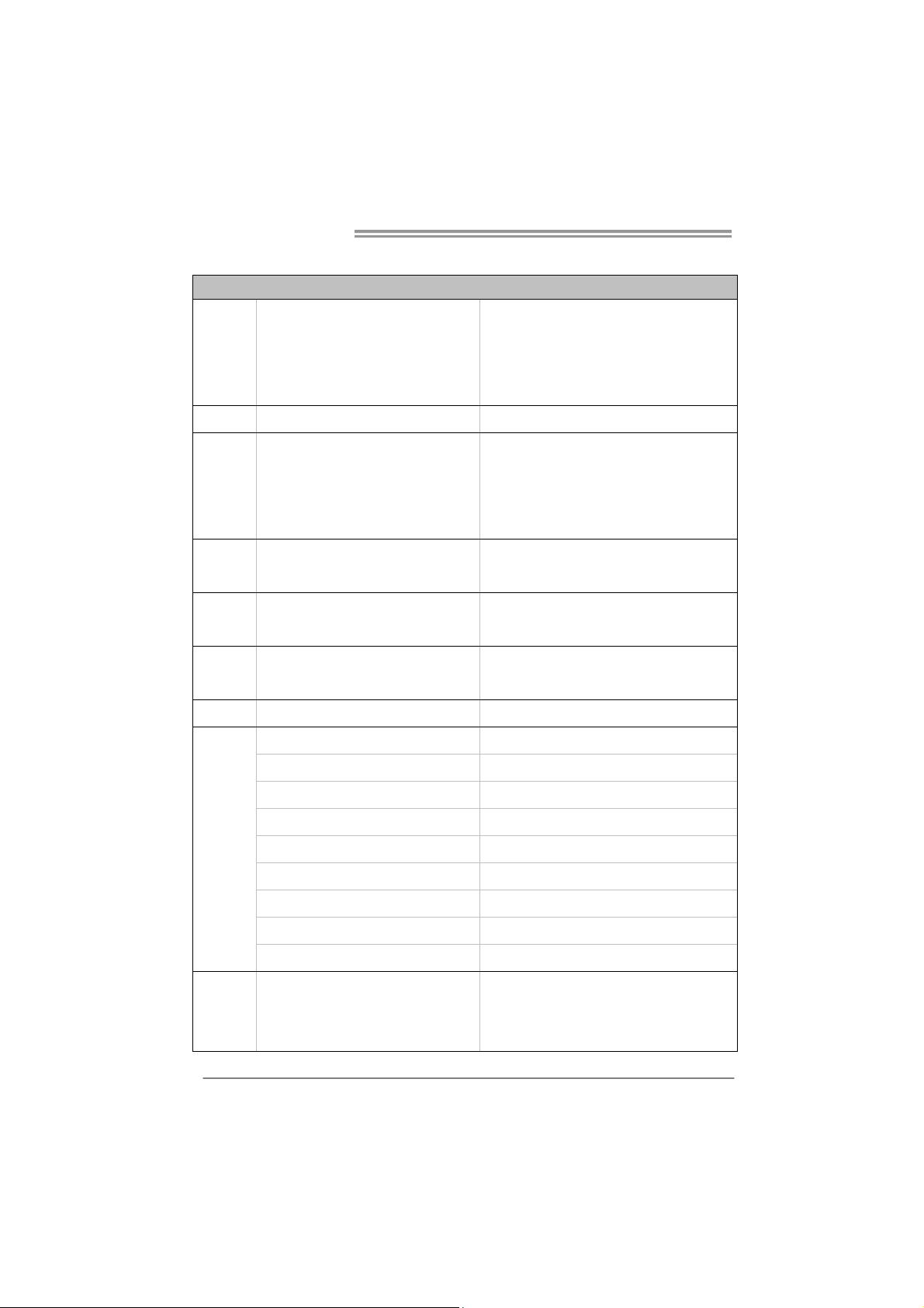
1.3 MOTHERBOARD FEATURES
SPEC
CPU
Chipset
Main
Memory
SATA 2
LAN
Sound
Codec
Slots
Socket 1155
Int e l Core i7 / i5 / i3 / Pent ium / C elero n
processor
Max imum C PU T D P: 65Watt
Int e l H61
DDR3 DIMM Slots x 2
Max Memory Capacity 16GB
Each DIMM supports 512MB/
1GB/2GB/4GB/8GB DDR3
Integrated Serial ATA Controller
AR8152
VT1708S
PCI-E Gen2 x1 slot x1 Supports PCI-E Gen2 x1 expansion card
SATA2 Connector x2 Each co nne cto r s upp orts 1 SATA2 device
Sup ports Execute D isable Bit / Enh anced Inte l
SpeedSt ep® / Inte l Ar ch itecture-64 / Ext ended
Memory 64 Technology / V irtualization Technology
Hyper Threading
Dual Chan ne l Mode DDR 3 me mo ry mod u le
Supports DDR3 1066 / 1333 / 1600 (depending on
CPU)
Regis ter ed DIMM and ECC D IMM is not suppo rted
Data transfer rates up to 3.0 Gb/s
SATA Version 2.0 spe cif ic at ion co mpl ian t
10 / 100 Mb/s auto negot iation
Half / Full duplex capability
5.1 channels audio out
High Definition Audio
On Board
Connectors
Rear Panel
I/O
2
Front Panel Connector x1 Supports front panel facilities
Front Audio Connector x1 Supports front panel audio function
CPU Fan Header x1 CPU Fan power supply (with Smart Fan function)
System Fan Header x1 System Fan Power supply
Clear CMOS Head er x1 Rest ore CMOS d at a to fa cto ry def au lt
USB2.0 Co nnect or x1 Each co nne cto r support s 2 front panel USB2.0 po rts
Power Connector (24pin) x1 Connects to Power supp ly
Power Conn ector (4pin) x1 Connects to Power supply
VGA Port x1
LAN port x1
USB2.0 Port x4
Connect to D-SUB monitor
Connect to RJ-45 ethernet cable
Connect to USB2.0 devices
Page 5

Board Size
H61IL
SPEC
Audio Jack x3 Provide Audio-In/Out and Mic. connection
170 (W) x 170 (L) mm
OS Support
Windows XP / Vista / 7
Biostar reserves the r ight to add or remove support
for any OS with or without notice
1.4 REAR PANEL CONNECTORS
NOTE:
z VGA O utput req uires a n Inte l Core family p rocessor with Intel Graphics Tec hnology.
z Maximum resolution: VGA: 2048 x 1536 @75Hz
3
Page 6
Motherboard Manual
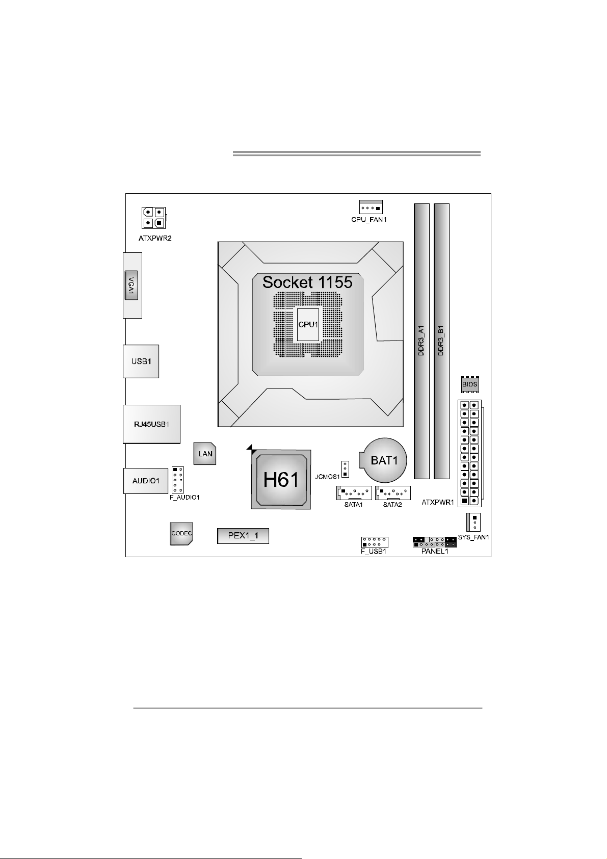
1.5 MOTHERBOARD LAYOUT
4
Note: represents the 1■
st
pin.
Page 7
CHAPTER 2: HARDWARE INSTALLATION
H61IL
2.1 I
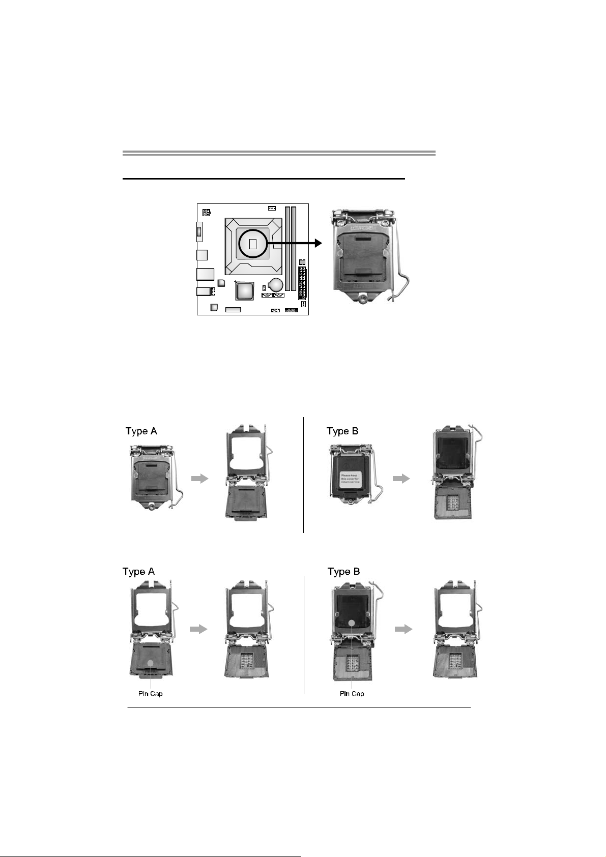
NSTALLING CENTRAL PROCESSING UNIT (CPU)
Notice:
1. Remove Pin Cap before installation, and make good preservation for future use.
When the CPU is removed, cover the Pin Cap on the empty socket to ensure pin
legs won’t be damaged.
2. The motherboard might equip with two different types of pin cap. Please refer
below instruction to remove the pin cap.
Step 1: Pull the socket locking lever out from the socket then raise the
lever and load plate to the fully open position.
Step 2: Remove the Pin Cap.
5
Page 8
Motherboard Manual
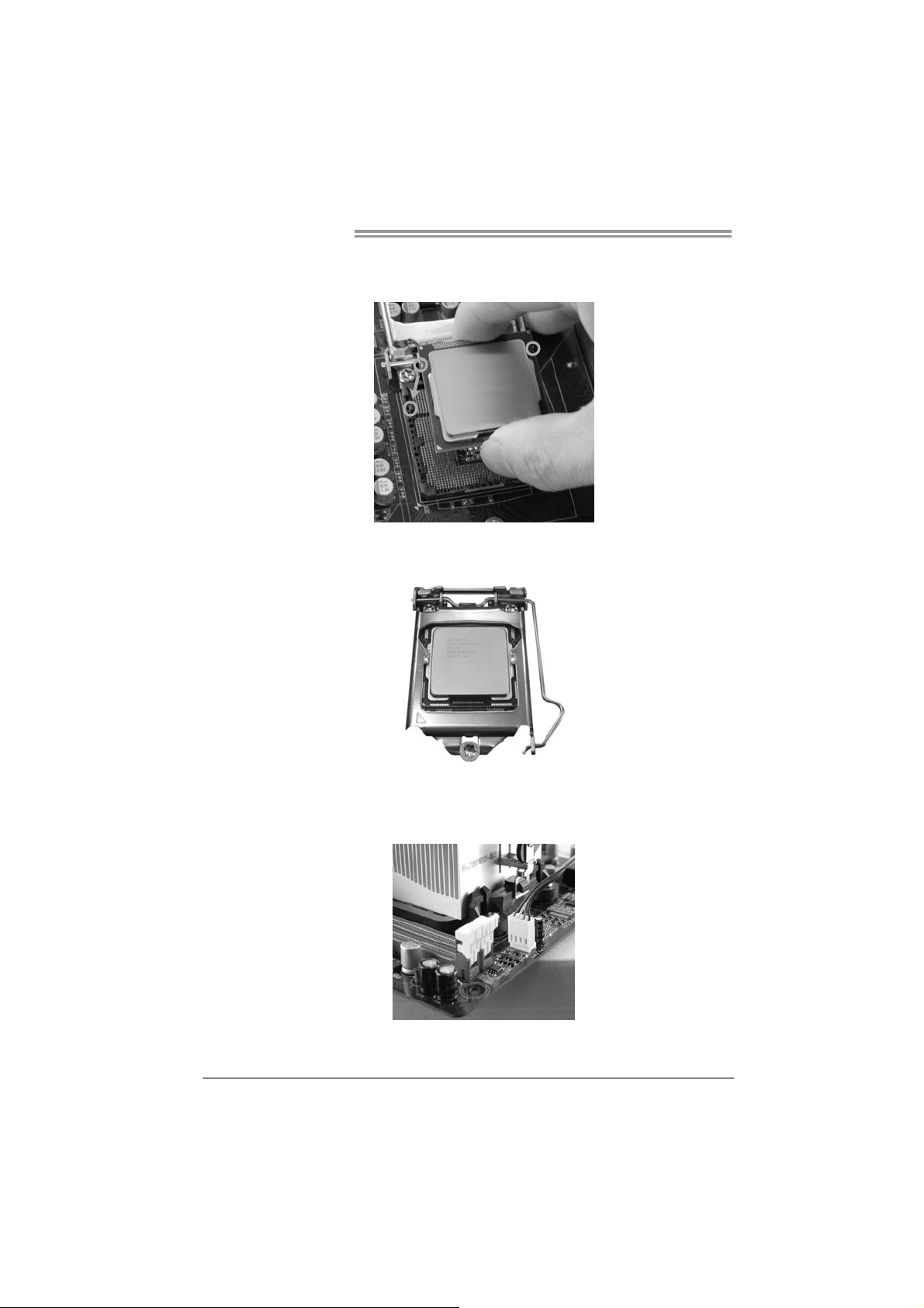
Step 3: Hold processor with your thumb and index fingers, oriented as
shown. Align the notches with the socket. Lower the processor
straight down without tilting or sliding the processor in the socket.
Step 4: Close the load plate. Pressing down on the load plate, close and
engage the socket lever.
Step 5: Put the CPU Fan and heatsink assembly on the CPU and buckle it
on the retention frame. Connect the CPU FAN power cable into
the CPU_FAN1 to complete the installation.
6
Page 9
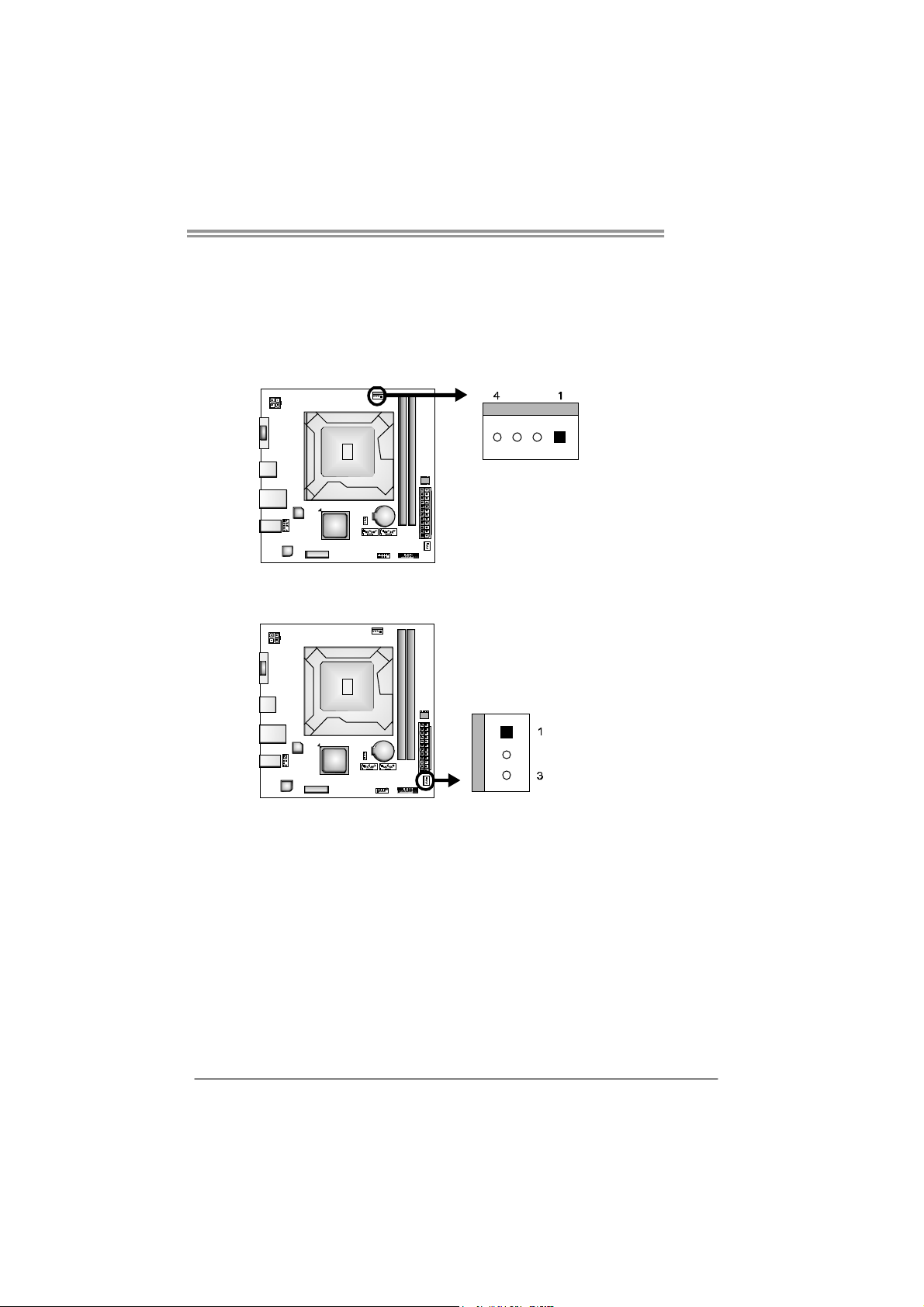
2.2 FAN HEADERS
These fan headers support cooling-fans built in the computer. The fan
cable and connector may be different according to the fan manufact urer.
Connect the fan cable to the connector while matching the black wire to
pin#1.
CPU_FAN1: CPU Fan Header
SYS_FAN1: System Fan Header
Note:
The SYS_FAN1 support 3-pin head connectors; the CPU_FAN1 supports 4-pin head
connector. When connecting with wires onto connectors, please note that the red wire is
the positive and should be connected to pi n#2, and the black wire is Ground and should
be connected to GND.
Assignment
Pin
1 Ground
2 +12V
3
FAN RPM rate sense
4 Smart Fan Control
Assignment
Pin
1 Ground
2 +12V
3 FAN RPM rate sense
H61IL
7
Page 10

Motherboard Manual
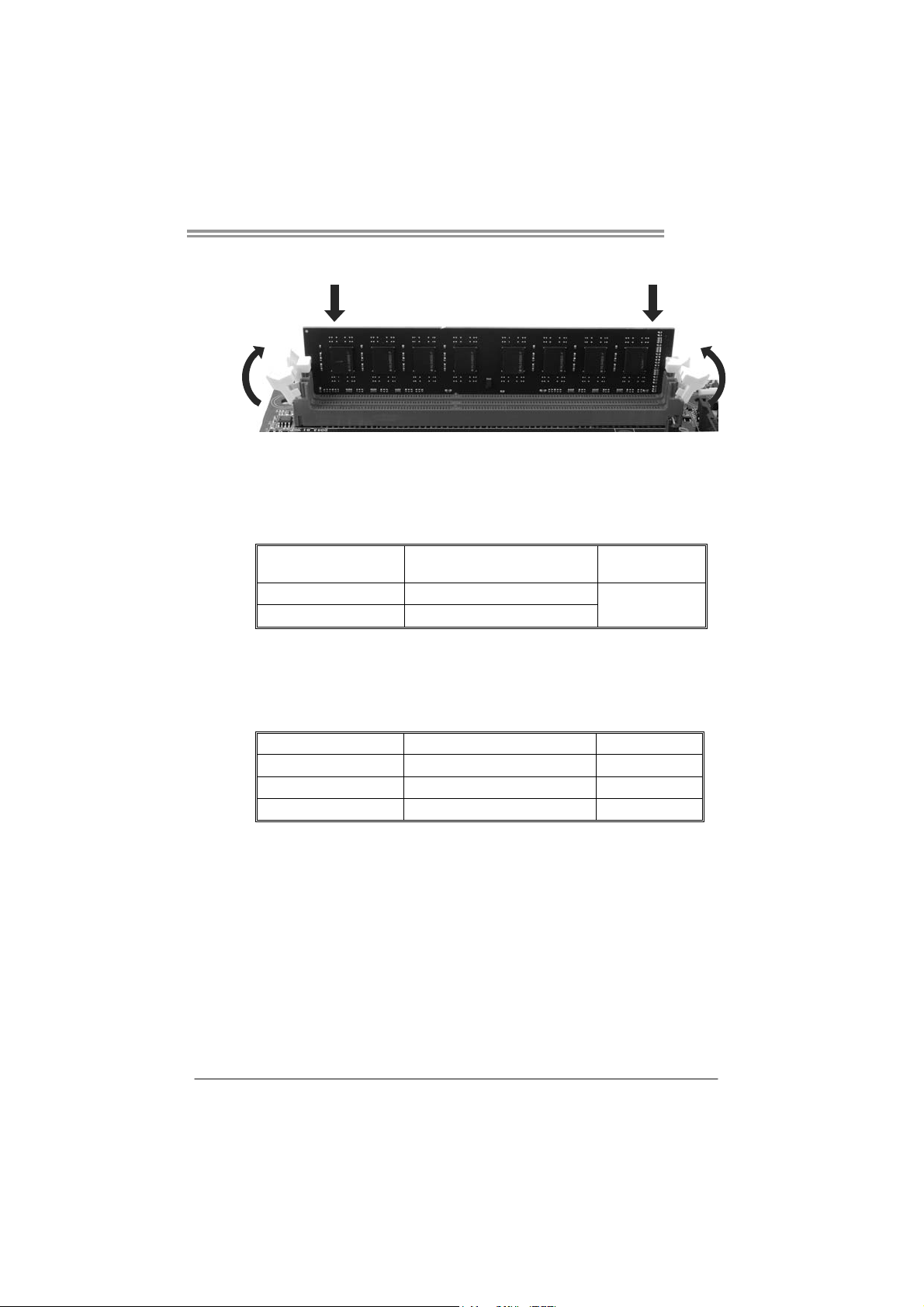
2.3 INSTALLING SYSTEM MEMORY
A. Memory Modules
1. Unlock a DIMM slot by pressing the retaining clips outward. Align a
DIMM on the slot such that the notch on the DIMM matches the
break on the Slot.
8
Page 11
H61IL
2. Insert the DIMM vertically and firmly into the slot until the retaining
chip snap back in place and the DIMM is properly seated.
Note:
If the DIMM does not go in smoothly, do not force it. Pull it all the way out
and try again.
B. Memory Capacity
DIMM Socket
Location
DDR3_A1 512MB/1GB/2GB/4GB/8GB
DDR3_B1 512MB/1GB/2GB/4GB/8GB
C. Dual Channel Memory Installation
Please refer to the following requirements to activate Dual Channel function:
Install memory module of the same density in pairs, shown in the table.
Dual Channel Status
Disabled O X
Disabled X O
Enabled O O
(O means memory installed; X, not installed.)
The DRAM bus width of the memory module must be the same(x8 or
x16)
DDR3 Module
DDR3_A1
Total Mem ory
Size
Max is 16GB.
DDR3_B1
9
Page 12
Motherboard Manual
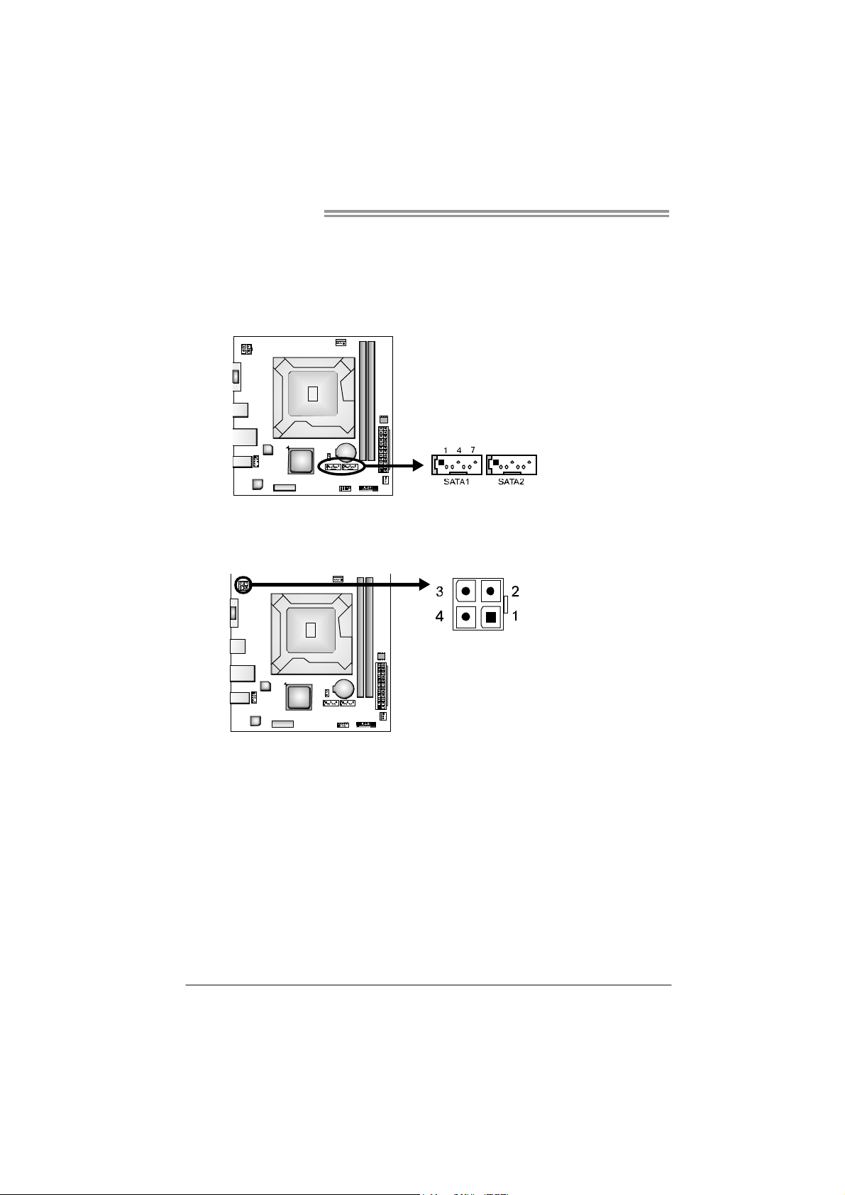
2.4 CONNECTORS AND SLOTS
SATA1~SATA2: Serial ATA Connectors
The motherboard has a PCI to SATA Controller with 2 channels SATA2 interface,
it satisfies the SATA 2.0 spec and with transfer rate of 3.0Gb/s.
ATXP W R2: ATX Power Source Connector
This connector provides +12V to CPU power circuit.
Assignment
Pin
1 Ground
2 TX+
3 TX4 Ground
5 RX6 RX+
7 Ground
Pin
Assignment
1 +12V
2 +12V
3 Ground
4 Ground
10
Page 13
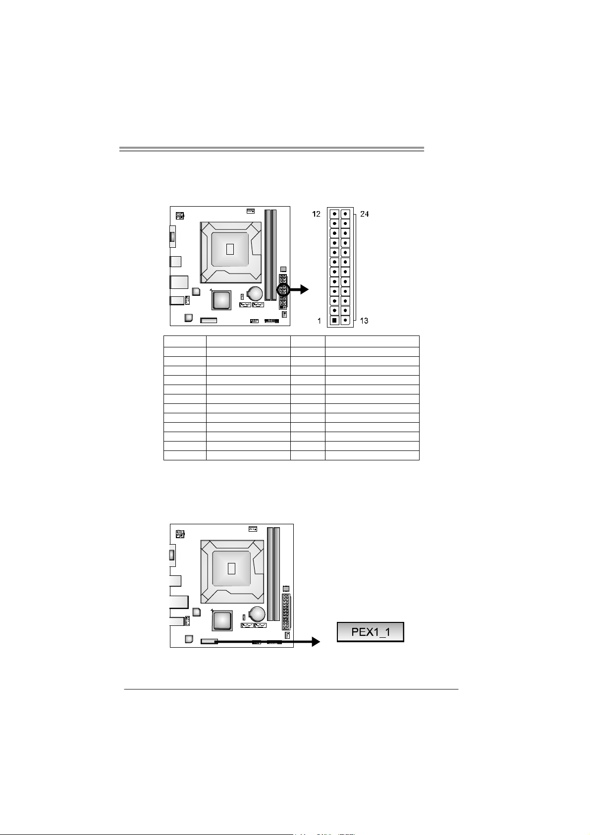
ATXP W R1: ATX Power Source Connector
This connector allows user to connect 24-pin power connector on the ATX
power supply.
Pin Assignment Pin Assignment
13 +3.3V 1 +3.3V
14 -12V 2 +3.3V
15 Ground 3 Ground
16 PS_ON 4 +5V
17 Ground 5 Ground
18 Ground 6 +5V
19 Ground 7 Ground
20 NC 8 PW_OK
21 +5V 9 Standby Voltage+5V
22 +5V 10 +12V
23 +5V 11 +12V
24 Ground 12 +3.3V
H61IL
PEX1_1: PCI-Express Gen2 x1 Slot
- PCI-Express 2.0 compliant.
- Data transfer bandwidth up to 500MB/s per direction; 1GB/s in total.
- PCI-Express supports a raw bit-rate of 5Gb/s on the data pins.
11
Page 14

Motherboard Manual
CHAPTER 3: HEADERS & JUMPERS SETUP
3.1 H
OW TO SETUP JUMPERS
The illustration shows how to set up jumpers. When the jumper cap is
placed on pins, the jumper is “close”, if not, that means the jumper is
“open”.
Pin opened Pin closed Pin1-2 closed
3.2 DETAIL SETTINGS
PANEL1: Front Panel Header
This 16-pin connector includes Power-on, Reset, HDD LED, Power LED, and
speaker connection. It allows user to connect the PC case’s front panel switch
functions.
12
Pin Assignment Function Pin Assignment Function
1 +5V
2 N/A 10 N/A
3 N/ A 1 1 N/ A N/A
4 Speaker 12 Power LED (+)
5 HDD LED (+)
6 HDD LED (-) 14 Power LED (-)
7 Ground
8 Reset control 16 Ground
Speaker
Connector
Hard drive
LED
Reset button
9 N/A
13 Power LED (+)
15 Power button
N/A
Power LED
Power-on button
Page 15

H61IL
F_USB1: Headers for USB 2.0 Ports at Front Panel
The header allows user to connect additional USB cable on the PC front panel,
and also can be connected with internal USB devices, like USB card reader.
Assignment
Pin
1 +5V (fused)
2 +5V (fused)
3 USB4 USB5 USB+
6 USB+
7 Ground
8 Ground
9 Key
10 NC
F_AUDIO1: Front Panel Audio Header
This header allows user to connect the front audio output cable with the PC front
panel. This header supports HD and AC’97 audio front panel connector.
HD Audio AC’97
Pin Assignment Pin Assignment
1 Mic Left in 1 Mic In
2 Ground 2 Ground
3 Mic Right in 3 Mic Power
4 GPIO 4 Audio Power
5 Right line in 5 RT Line Out
6 Jack Sense 6 RT Line Out
7 Front Sense 7 Reserved
8 Key 8 Key
9 Left line in 9 LFT Line Out
10 Jack Sense 10 LFT Line Out
Note1: It is recommended that you connect a high-definition front panel audio module to
this connector to avail of the motherboard's high definition audio capability.
Note2: Please try to disable the "Front Panel Jack Detection" if you want to use an
AC'97 front audio output cable. The function can be found via O.S. Audio Utility.
13
Page 16

Motherboard Manual
JCMOS1: Clear CMOS Header
Placing the jumper on pin2-3 allows user to restore the BIOS safe setting and
the CMOS data. Please carefully follow the procedures to avoid damaging the
motherboard.
※ Clear CMOS Procedures:
1. Remove AC power line.
2. Set the jumper to “Pin 2-3 close” .
3. Wait for five seconds.
4. Set the jumper to “Pin 1-2 close” .
5. Power on the AC.
6. Load Optimal Defaults and save settings in CMOS.
13
Pin 1-2 Close:
Normal Operation (default).
Pin 2-3 Close:
Clear CMOS data.
13
14
Page 17

CHAPTER 4: USEFUL HELP
H61IL
4.1 D
RIVER INSTALLATION NOTE
After you installed your operating system, please insert the Fully Setup
Driver DVD into your optical drive and install the driver for better system
performance.
You will see the following window after you insert the DVD
The setup guide will auto detect your motherboard and operating system.
Note:
If this window didn’t show up after you insert the Driver DVD, please use file browser to
locate and execute the file SETUP.EXE under your optical drive.
A. Driver Installation
To install the driver, please click on the Driver icon. The setup guide will
list the compatible driver for your motherboard and operating system.
Click on each device driver to launch the installation program.
B. Software Installation
To install the software, please click on the Software icon. The setup guide
will list the software available for your system, click on each software title
to launch the installation program.
C. Manual
Aside from the paperback manual, we also provide manual in the Driver
DVD. Click on the Manual icon to browse for available manual.
Note:
Yo u will need Acrobat Reader to open the manual file. Please download the latest version
of Acrobat Reader software from
http://www.adobe.com/products/acrobat/readstep2.html
15
Page 18

Motherboard Manual
e
4.2 SOFTWARE
Installing Software
1. Insert the Setup DVD to the optical drive. The drivers installation program
would appear if the Autorun function has been enabled.
2. Select Software Installatio n, and then click on the respective software
title.
3. Follow the on-screen instructions to complete the installation.
Launching Software
After the installation process, you will see the software icon “eHOT Line” /
“BIOS Update” appears on the desktop. Double-click the icon to launch the
utility.
eHot-Line (Optional)
eHot-Line is a convenient utility that helps you to contact with our
Tech-Support system. This utility will collect the system information which is
useful for analyzing the problem you may have encountered, and then send
these information to our tech-support department to help you fix the problem.
Before you use this uti lity, please set Outlook Express as your default e-mail client applicatio n progra m.
re pr esent s im por ta nt
*
information that you
must provide. Without
this information, y ou may
not be able to send out
the mail.
This block will show
the information which
would be collected in
the mail.
Describe condition
*
of your system.
Select your area or
*
the area close to you.
Provide the e-mail
address that you would
like to send the copy to.
Pr ovid e the na me of
*
the memory module
manufacturer.
Provide the name of
th e powe r su ppl y
manufacturer and the
model no.
Se nd th e mai l out .
Sav e the se infor ma tion to a .t xt fil
Exit this dialog.
16
Page 19

H61IL
After filling up this informatio n, click “Send”
to send the mail out. A warning dialog would
appear asking for your confirmation; click
“Send” to confirm or “Do Not Send” to cancel.
If you want to save this information to a .txt file, click “Save As…” and then you
will see a saving dialog appears asking you to enter file name.
Enter the file name and then click
“Save”. Your system information
will be saved to a .txt file.
Open the saved .txt file, you will see
your system information including
motherboard/BIOS/CPU/video/
device/OS information. This
information is also concluded in the
sent mail.
We will not share customer ’s data with any other third parties,
so please feel free to provide your system information while using
eHot-Line service.
If you are not using Outlook Express as your default e-mail client
application, you may need to save the system information to a .txt file
and send the file to our tech support with other e-mail application.
Go to the following web
http://www.biostar.com.tw/app/en/about/contact.php for getting our
contact information.
17
Page 20

Motherboard Manual
n
BIOS Update
BIOS Update is a convenient utility which allows you to update your
motherboard BIOS under Windows system.
Sh ow current B IOS in format io
Update BIOS
from the Internet
with a BIOS fil e
Update BIOS
Save current BIOS
to a .bin file
<Backup BIOS>
Once click on this button, the saving
dialog will show. Choose the
position to save file and enter file
name. (We recommend that the file
name should be English/number
and no longer than 7 characters.)
Then click Save.
18
Page 21

H61IL
<Update BIOS>
Before doing this, please download the proper BIOS file from the website.
Then click Update BIOS button, a
dialog will show for asking you backup
current BIOS. Click Yes for BIOS
backup and refer to the Backup BIOS
procedure; or click No to skip this
procedure.
After the BIOS Backup procedure, the
open dialog will show for requesting the
BIOS file which is going to be updated.
Please choose the proper BIOS file for
updating, then click on Open.
The utility will update BIOS with the
proper BIOS file, and this process may
take minutes. Please do not open any
other applications during this process.
After the BIOS Update process, click on
OK to restart the system.
While the system boots up and the full screen logo shows, press <Delete>
key to enter BIOS setup.
In the BIOS setup, use the Load Optimized Defaults function and then Save and
Exit Setup to exit BIOS setup. BIOS Update is completed.
All the information and content above about the software are subject to be changed
without notice. For better performance, the software is being co ntinuously updated.
The information and pictures described above are for your reference only. The actual
information and settings on board may be slightly different from this manual.
19
Page 22

Motherboard Manual
4.3 EXTRA INFORMATION
CPU Overheated
If the system shuts down automatically after system is powered on for
seconds, the phenomenon means the CPU protection function has
been activated.
When the CPU is over heated, the motherboard will shutdow n
automatically to avoid a damage of the CPU, and the system may not
power on again.
In this case, please double check:
1. The CPU cooler surface is placed evenly with the CPU surface.
2. CPU fan is rotated normally.
3. CPU fan speed is fulfilling with the CPU speed.
After confirmed, please follow steps below to relief the CPU protection
function.
1. Remove the power cord from power supply for seconds.
2. Wait for seconds.
3. Plug in the power cord and boot up the system.
Or you can:
1. Clear the CMOS data.
(See “Close CMOS Header: JCMOS1” section)
2. Wait for seconds.
3. Power on the system again.
20
Page 23

4.4 AMI BIOS BEEP CODE
Boot Block Beep Codes
Number of Beeps De scription
1 No media present. (Insert diskette in floppy drive A:)
2
3 Insert next diskette if multiple diskettes are used for recovery
4 Flash Programming successful
5 File read error
7 No Flash EPROM detected
10 Flash Erase error
11 Flash Program error
12 “AMIBOOT.ROM” file size error
13
POST BIOS Beep Codes
Number of Beeps De scription
1 Memory refresh timer error
3 Base memory read/write test error
6 Keyboard controller BAT command failed
7 General exception error (processor exception interrupt error)
8 Display memory error (system video adapter)
“AMIBOOT.ROM” file not found in root directory of diskette in
A:
BIOS ROM image mismatch (file layout does not match
image present in flash device)
H61IL
Troubleshooting POST BIOS Beep Codes
Number of Beeps Troubleshooting Action
1, 3 Reseat the memory, or replace with known good modules.
Fatal error indicating a serious problem with the system.
Consult your system manufacturer. Before declaring the
motherboard beyond all hope, eliminate the possibility of
interference by a malfunctioning add-in card. Remove all
expansion cards except the video adapter.
z If beep codes are generated when all other expansion
6, 7
8
cards are absent, consult your system manufacturer’s
technical support.
z If beep codes are not generated when all other expansion
cards are absent, one of the add-in cards is causing the
malfunction. Insert the cards back into the system one at a
time until the problem happens again. This will reveal the
malfunctioning card.
If the system video adapter is an add-in card, replace or
reseat the
video adapter. If the video adapter is an integrated part of the
system board, the board may be faulty.
21
Page 24

Motherboard Manual
4.5 TROUBLESHOOTING
Probable Solution
1. There is no power in the system.
Power LED does not shine; the
fan of the power supply does not
work
2. Indicator light on keyboard does
not shine.
System is inoperative. Keyboard lights
are on, power indicator lights are lit,
and hard drives are running.
System does not boot from a hard disk
drive, but can be booted from optical
drive.
System only boots from an optical
drive. Hard disks can be read,
applications can be used, but system
fails to boot from a hard disk.
Screen message shows “Invalid
Configuration” or “CMOS Failure.”
System cannot boot after user installs a
second hard drive.
1. Make sure power cable is
securely plugged in.
2. Replace cable.
3. Contact technical support.
Using even pressure on both ends of
the DIMM, press down firmly until the
module snaps into place.
1. Check cable running from disk to
disk controller board. Make sure
both ends are securely plugged
in; check the drive type in the
standard CMOS setup.
2. Backing up the hard drive is
extremely important. All hard
disks are capable of breaking
down at any time.
1. Back up data and applications
files.
2. Reformat the hard drive.
Re-install applications and data
using backup disks.
Review system’s equipment. Make sure
correct information is in setup.
1. Set master/slave jumpers
correctly.
2. Run SETUP program and select
correct drive types. Call the drive
manufacturers for compatibility
with other drives.
22
Page 25

H61IL
This page is intentionally left blank.
23
Page 26

Motherboard Manual
APPENDIX: SPEC IN OTHER LANGUAGES
G
ERMAN
Sp ezif ika tio nen
CPU
Chipsatz
Arbeitsspeich
er
SATA 2
LAN
HD
Audio-Unters
tützung
Steckplätz e
Socket 1155
Int e l Core i7 / i5 / i3 / Pent ium / C elero n
Prozessoren
Int e l H61
DDR3 DIMM-Steckplätze x 2
Max. 16GB Arbeitss peicher
Jeder DIMM unterstützt 512MB/
1GB/2GB/4GB/8GB DDR3.
Integrierter Serial ATA-Controller
AR8152
VT1708S
PCI-E Gen2 x1-Steckplatz x1
SATA2-Anschluss x2 Jeder Anschluss unterstützt 1 SATA2-Laufwerk
Unterstützt Execute Disable Bit / Enhanced Intel
SpeedSt ep® / Inte l Ar ch itecture-64 / Ext ended
Memory 64 Technology / V irtualization Technology /
Hyper Threading
Dual-Kanal DDR3 Speichermodul
Unterstützt DDR3 1066 / 1333 / 1600
registrierte DIMMs. ECC DIMMs werden nicht
unterstützt.
Datentransferrate b is zu 3.0Gb /s
Konform mit der SATA-Spezifikation Version 2.0
10 / 100 Mb/s Auto-Negotiation
Halb-/ Vollduplex-Funktion
Unterstützt High-Definition Audio
5.1-Kanal-Audioausgabe
Onboard-Ans
chluss
24
Fronttafelanschluss x1 Unterstützt die Fronttafelfunktionen
Front-Audioanschluss x1 Unterstützt die Fronttafel-Audioanschlussfunktion
CPU-Lüfterstromversorgungsanschluss (mit Smart
CPU-Lüfter-Sockel x1
Fan -F un ktio n)
System-Lüfter-Sockel x1 System-Lüfter-Stromversorgungsanschluss
"CMOS löschen"-S ockel x1
USB2.0-Anschluss x1 Jeder Anschluss unterstützt 2
Front taf el-US B2. 0-A ns chlüs se
Stromanschluss (24-polig) x1
Page 27

Sp ezif ika tio nen
St r omansch lu s s (4 -po l ig ) x1
H61IL
Rückseiten-E
/A
Platinengröße
OS-Unterstüt
zung
VGA-Anschluss x1
LAN-Anschluss x1
USB2.0-Anschluss x4
Audioanschluss x3
170 mm (B) X 170 mm (L)
Windows XP / Vista / 7
Biostar behält sich das Recht vor, ohne Ankündigung
die Unterstützung für ein Betriebssystem
hinzuzufügen oder zu entfernen.
25
Page 28

Motherboard Manual
FRENCH
SPEC
UC
Chipset
Mémoire
principale
SATA 2
LAN
Pris e en
charg e
aud io HD
Fentes
Socket 1155
Pro c esseurs Int e l Cor e i7 / i5 / i3 / Pent ium /
Celeron
Int e l H61
Fentes DDR3 DIMM x 2
Cap acit é mé mo ir e max imal e de 16 Go
Chaque DIMM prend en charge des DDR3 de
512Mo/1Go/2Go/4Go/8Go
Contrô leur Serial ATA int é gr é
AR8152
VT1708S
Fente PCI-E Gen2 x1 x1
Connecteur SATA2 x2
Prend en cha rge les techno log ies d'ex écution d e b it
de désactivation / Intel SpeedStep® optimisée/
d'architect ure Intel 64 / de mémo ire étendue 64 / de
virtualisat ion / Hyper Threading
Mod u le d e mémo ir e DDR 3 à mod e à d oub le vo ie
Prend en charge la DDR3 1066 / 1333 / 1600
Les DIMM à registres et DIMM avec code correcteurs
d'erreurs ne sont pas prises en charge
Taux de transfert jusqu'à 3.0Go/s.
Co n fo rme à la spécif icat ion SATA Vers io n 2.0
10 / 100 Mb/s négociation automatique
Half / Full duplex capability
Pris e en charg e de l'aud io haut e défin it ion
Sortie aud io à 5 .1 vo ies
Chaque connect eur p rend en ch arge 1 pér ip hér iqu e
SATA2
Connecteur
embarqu é
26
Connecteur du panneau avant x1 Prend en charge les équipements du panneau avant
Connect eur Aud io du p ann eau avant x 1 Prend en ch arge la fonct ion aud io du panneau avant
Alimentation électrique du ventilateur UC (avec
Embase de ventilateur UC x1
fonction de ventilateur intelligent)
Embase de ventilateur système x1 Alimentation électrique du ventilateur système
Embase d'effacement CMOS x1
Chaque connecteur prend en charge 2 ports USB2.0
Connecteur USB2.0 x1
de panneau avant
Page 29

SPEC
H61IL
E/S du
panneau
arr ière
Dimensions
de la carte
Support SE
Connecteur d'aliment at ion x1
(24 broches)
Connecteur d'aliment at ion x 1
(4 broch es )
Port VGA x1
Port LAN x1
Port US B2.0 x4
Fiche aud io x3
170 mm (l) X 170 mm (H)
Windows XP / Vista / 7
Biostar se réserve le droit d'ajouter ou de supprimer
le support de SE avec ou sans pr éavis
27
Page 30

Motherboard Manual
ITALIAN
SPECIFICA
CPU
Chipset
Memoria
principale
SATA 2
LAN
Supporto
audio HD
Allo g gi
Socket 1155
Pro ces s o re Int el Co re i7 / i5 / i3 /
Pentium / Celeron
Int e l H61
Allo g gi D IMM DDR 3 x 2
Cap acità mass ima della memoria 16GB
Ciascun DIMM supporta DDR3
512MB/1GB/2GB/4GB/8GB
Co n troller S er ial ATA int eg rat o
AR8152
VT1708S
Alloggio PCI Express Gen2 x1 x1
Sup porto di Ex ecute Disable Bit / Enhanced
Intel SpeedStep® / Architettura Intel 64 /
Tecnologia Extended Memory 64 / Tecnologia
Virtualization / Hyper Threading
Modulo di memoria DDR3 a canale doppio
Supporto di DDR3 1066 / 1333 / 1600
DIMM registrati e DIMM ECC non sono
supportati
Velocità di trasferimento dei dati fino a
3.0Gb/s.
Co mp at ib ile s pec ifiche S ATA Vers io n e 2 .0
Negoziazione automatica 10 / 100 Mb/s
Capacità Half / Full Duplex
Supporto audio High-Definition (HD)
Uscita audio 5.1 canali
Connettori
su scheda
28
Connettore SATA2 x2 Ciascun connettore supporta 1 unità SATA2
Co n nettore pan nello fr o ntale x 1 Suppo r ta i s er viz i d e l pann e llo f ron t ale
Connettore audio frontale x1 Supporta la funzione audio pannello frontale
Alimentazione ventolina CPU (con funzione
Co llet t o re vent o lina C PU x1
Smart Fan)
Co llet t o re vent o lina sistema x1 Alimentazione v entol ina d i s is t ema
Co llet t o re cance l laz io ne CMO S x 1
Ciascun connettore supporta 2 porte USB2.0
Connettore USB2.0 x1
pannello frontale
Connettore alimentazione x1
(24 pin)
Page 31

SPECIFICA
H61IL
I/O
pannello
posteriore
Dimension
i scheda
Sistemi
operat ivi
supportati
Connettore alimentazione x1
(4 pin)
Porta VGA x1
Porta LAN x1
Porta USB2.0 x4
Connettore audio x3
170 mm (larghezza) x 170 mm
(altez za)
Windows XP / Vista / 7
Biostar si riserva il diritto di aggiungere o
rimuovere il supporto di qualsiasi sistema
operativo senza preavviso.
29
Page 32

Motherboard Manual
SPANISH
Especificación
CPU
Conjunto de
chips
Memoria
principal
SATA 2
Red Local
Soporte de
sonido HD
Ranuras
Socket 1155
Pro c esador Intel Cor e i7 / i5 / i3 / Pent iu m /
Celeron
Int e l H61
Ranuras DIMM DDR3 x 2
Capacidad máxima de memoria de 16GB
Cada DIMM admite DDR de
512MB/1GB/2GB/4GB/8GB
Controlador ATA Serie Integrado
AR8152
VT1708S
Ranura PCI-E Gen2 x 1 X1
Conector SATA2 X2 Cada conector soporta 1 dispositivos SATA2
Admite Bit de deshabilitación de ejecución / Intel
SpeedSt ep® Mej orado / Int e l Arch it ecture-64 /
Tecnolog ía Extended Memor y 64 / Tecno log ía d e
virtualizac ión / Hyper Thr ead ing
Módulo de memoria DDR3 de canal Doble
Admite DDR3 de 1066 / 1333 / 1600
No admite DIMM registrados o DIMM compatib les
con ECC
Tasas de transferencia de hasta 3.0 Gb/s.
Co mp at ible con la ve rsión S ATA 2.0
Negociación de 10 / 100 Mb/s
Funciones Half / Full dúplex
Soporte de sonido de Alta Definición
Salida de sonido de 5.1 canales
Conectores
en placa
30
Conector de panel frontal X1 Soporta instalaciones en el panel frontal
Conector de sonido frontal X1 Soporta funciones de sonido en el panel frontal
Cabecera de ventilador de CPU X1 Fuente de alimentación de ventilador de CPU (con
función Smart Fan)
Cabecera de ventilador de sistema X1 Fuente de alimentación de ventilador de sistema
Cabecera de borrado de CMOS X1
Conector USB2.0 X1 Cada conector so po rta 2 puert os USB2.0 fronta les
Conector de alimentación X1
(24 patillas)
Page 33

Especificación
H61IL
Panel
trasero de
E/S
Ta mañ o d e
la placa
Soporte de
sistema
operativo
Conector de alimentación X1
(4 patillas)
Puert o VGA X 1
Puerto de red local X1
Puert o USB2.0 X4
Conector de sonido X3
170 mm. (A) X 170 Mm. (H)
Windows XP / Vista / 7
Biostar se reserva el derecho de añadir o retirar el
soporte de cualquier SO con o sin aviso previo.
31
Page 34

Motherboard Manual
PORTUGUESE
ESPECIFICAÇÕES
Socket 1155
CPU
Chipset Intel H61
Memória
principal
SATA 2 Controlador Serial ATA integrado
LAN AR8152
Suporte
para áudio
de alta
definição
Pro c essador Int e l Cor e i7 / i5 / i3 / Pent iu m /
Celeron
Ranhuras DIMM DDR3 x 2
Cap acid ad e máx ima d e memór i a: 16 GB
Cada módulo DIMM suporta uma memória
DDR3 de 512MB/ 1GB/2GB /4GB/8GB
VT1708S
Sup orta as tecno log ias Execute D isable Bit /
Enhanced Int el SpeedStep® / Inte l Arqu itecture -64
/ Extended Memor y 64 / Virtualiz at ion / Hyper
Threading
Módulo de memória DDR3 de canal duplo
Suporta módulos DDR3 1066 / 1333 / 1600
Os módulos DIMM registados e os DIMM ECC não
são suportados
Velocidades de transmissão de dados até 3.0 Gb/s.
Compat ib ilidade co m a espec ificação S ATA ve rsão
2.0
Auto negociação de 10 / 100 Mb/s
Capacidade semi/full-duplex
Suporta a especificação High-Definition Audio
Saída de áudio de 5.1 canais
Ranhuras Ranhura PCI-E Gen2 x 1 x1
Conector SATA2 x2 Cada conector suporta 1 dispositivo SATA2
Conector do pa inel frontal x1 Para suporte de várias funções no painel frontal
Conector de áud io fronta l x1 Suporta a fun ção de áud io no p aine l fron ta l
Conectores
na placa
Conector da vento inha da CPU x1
Conector da ventoinha do s istema x1 Alimentação da vento inha do sistema
Conector para limpeza do CMOS x1
Conector USB2.0 x1
Conector de alimentação x1
(24 pinos)
32
Alimentação da ventoinha da CPU (com a função
Smart Fan)
Cada conector suporta 2 portas USB2.0 no painel
frontal
Page 35

Ent radas/S
aídas no
painel
traseiro
Tamanho
da placa
Sistemas
operativos
suportados
ESPECIFICAÇÕES
Conector de alimentação x1
(4 p inos)
Porta VGA x1
Porta LAN x1
Porta USB2.0 x4
Tomada de áudio x3
170 mm (L) X 170 mm (A)
Windows XP / Vista / 7
H61IL
A Biostar reserva-se o direito de adicionar ou
remover suporte para qualquer sistema operativo
com ou sem a v iso p révio .
33
Page 36

Motherboard Manual
/
POLISH
SPEC
Procesor
Chipset
Pam ięć
główna
SATA 2
LAN
Obsługa
aud io HD
Gniazda
Socket 1155
Obsługa Execute D is able B it / Enhanced Intel
SpeedSt ep® / Inte l Ar ch itecture-64 / Ext ended
Pro c esor Int e l Cor e i7 / i5 / i3 / Pent ium /
Memory 64 Technology / V irtualization Technology
Celeron
Hyper Threading
Int e l H61
Gniazda DDR3 DIMM x 2
Mod uł pamięci DDR3 z trybem podwójnego kanału
Maks. wielkość pamięci 16GB
Obsługa DDR3 1066 / 1333 / 1600
Każde gniazdo DIMM obs ługuje moduły
Brak obsługi Registered DIMM oraz ECC DIMM
512MB/1GB/2GB/4GB/8GB DDR3
Transfer danych do 3.0 Gb/s.
Zintegrowany kontroler Serial ATA
Zgodność ze specyfikacją SATA w wers j i 2. 0
10 / 100 Mb/s z automatyczną negocjacją szybkości
AR8152
Działanie w tryb ie połowicznego / pełn ego dupleksu
Obsługa H ig h- Def in it ion A ud io
VT1708S
5.1 kanałowe wyjście audio
Gniazdo PCI-E Gen2 x 1 x1
Złącze SATA2 x2 Każde złącze obsługuje 1 urządzenie SATA2
Złącza
wbud owane
34
Złącze panela przedniego x1 Obsługa elementów panela przedniego
Przedn ie złącze aud io x1 Obs ługa funkcji audio na panelu przednim
Złącze główkow e went ylatora
procesora x1
Złącze główkow e went ylatora
systemowego x1
Złącze główkowe kasowan ia CMOS x 1
Złącze USB2.0 x1
Złącze zas ilania (24 pinowe) x1
Złącze zas ilania (4 p ino we) x1
Zasilanie wentylatora procesora (z funkcją Smart
Fan )
Zasilanie wentylatora systemowego
Każde złącze o bs ługuje 2 porty USB2.0 na panelu
przednim
Page 37

SPEC
H61IL
Back Panel
I/O
Wymiary
płyty
Obsluga
systemu
operacyjne
go
Port VGA x1
Port LAN x1
Port US B2.0 x4
Gniazdo audio x3
170 mm (S) X 170 mm (W)
Windows XP / Vista / 7
Biostar zastrzega sobie prawo dodawania lub
odwoływania ob sług i d owo lneg o s ys temu
operacyjneg o b ez powiadomien ia.
35
Page 38

Motherboard Manual
RUSSIAN
CPU
(центральн
ый
процессор)
Набо р
микросхем
Основная
память
SATA 2
Локальна я
сеть
Звуко вая
поддержка
жестког о
диска
Socket 1155
Процессор Inte l Co r e i7 / i5 / i3 / Pent iu m /
Celeron
Int e l H61
Слоты DDR3 DIMM x 2
Максимальная ёмкость памяти 16 ГБ
Каждый модуль DIMM поддерживает
512МБ /1ГБ/2ГБ/4ГБ/8ГБ DDR3
Встроенное последовательное устро йство
упра вления ATA
AR8152
VT1708S
СПЕЦ
Поддержка технологий Execut e D isab le Bit /
Enhanced Inte l Speed St ep® / Int el Arch itecture-64
/ Extended Memory 64 Technology / технологии
виртуализац ия / Hyper Threading
Мод ул ь памяти с двухканальн ым режимом DDR3
Поддержка DDR3 1066 / 1333 / 1600
Не поддерживает зарегистрированные модули
DIMM and ECC DIMM
скорость передачи данных до 3.0 гигабит/с.
Соответствие спецификации SATA версия 2.0
Автоматическо е согласование 10 / 100 Мб /с
Частичная / полна я дуплексная способность
Звуко вая поддержка H igh- D ef in ition
5.1канальный звуковой выход
Слоты Слот PCI-E Gen2 x 1 x1
Разъ ём SATA2 x2 Каждый разъём поддерживает 1 устройство SATA2
Разъ ём на лицевой панели x1 Поддержка устройс тв на лицевой панели
Входной звуковой разъём x1
Встроенны
й разъём
Контактирующее приспособление
вентил ятор а центрального процессора x1
Контактирующее приспособление
вентил ятор а системы x1
Открытое контактир ующее
приспособление CMOS x1
36
Поддержка звуко вых функций на лицевой
панели
Источник питания для вентилятор а центрального
процессора (с фун кц и ей интеллектуального
вентил ятор а)
Источник питания для вентилятора системы
Page 39

Задняя
панель
средств
ввода-выв
ода
Разм ер
панели
Поддержка
OS
СПЕЦ
USB2.0-разъём x1
Разъ ем питания (24 вы вод) x1
Разъ ем питания (4 вывод) x1
Пор т VGA x1
Пор т LAN x1
USB2.0-порт x4
Гнездо для подключени я
наушников x3
170 мм (Ш) X 170 мм (В)
Windows XP / Vista / 7
Каждый разъём поддерживает 2 USB2.0-порта на
лицевой панели
Biostar сохраняет за собой право добавлять или
удаля ть средства обеспечения для OS с или без
предварительного уведомле ния .
H61IL
37
Page 40

Motherboard Manual
/
و
ARABIC
تﺎﻔﺻاﻮﻤﻟا
تﺎﻴﻨﻘﺗ ﻢﻋﺪﺗExecute D isable Bit / Enhanced Inte l
SpeedSt ep® / Inte l Ar ch itecture-64 / Ext ended
Memory 64 Technology / Virtualization Technology
Hyp er T hr eading
Int e l H61
تﺎﺠﻟﺎﻌﻣIntel Co r e i7 / i5 / i3 / Pentiu m /
ﺔﺤﺘﻓDDR3 DIM M دﺪﻋ2
ﺔﺤﺘﻓ ﻞآ ﻢﻋﺪﺗDIMM عﻮﻥ ﻦﻣ ةﺮآاذ ﻢﻋﺪﺗ DDR3 ﺔﻌﺳ
ﻰﻟإ ﻞﺼﺗ تﺎﻋﺮﺴﺑ تﺎ ﻥﺎﻴﺒﻟا ﻞﻘﻥ3.0 ﺖﺑﺎﺠﻴﺝ/ﺔﻴﻥﺎ ﺛ.
تﺎﻔﺹاﻮﻤﻟ ﺔﻘﺑﺎﻄﻣSATA راﺪﺹﻹا 2.0
ﻦﻣ ﻒیﺮﻌﺘﻟا ﻲﻟ ﺎﻋ تﻮﺼﻟا ﺔﻴﻨﻘﺗ ﻢﻋﺪﺗ
ىﻮﺼﻗ ةﺮآاذ ﺔﻌﺳ16 ﺖیﺎﺑ ﺎﺠﻴﺝ
/512 و ﺖیﺎﺑ ﺎﺠﻴﻣ1/
ﻞﻣﺎﻜﻟا جودﺰﻤﻟا ﻞﻘﻨﻟا ﺔﻴﻥﺎﻜﻣإ/ﻲﻔﺼﻨﻟا
عﻮﻥ ﻦﻣ ةﺮآاﺬﻟا ﻢﻋﺪﺗ DDR3 تﺎﻌﺳ 1066 / 136 6 / 1600
و2/ و4/ و8 ﺎﺠﻴﺝﺖیﺎﺑ
ضوﺎﻔﺗ ﻲﺋﺎﻘﻠﺗ10/100 ﺖیﺎﺑ ﺎﺠﻴﻣ /ﺔﻴﻥﺎﺛ
5.1 تﻮﺼﻟا جﺮﺨﻟ تاﻮﻨﻗ
ةﺮآاﺬﻟا ﻖﺋﺎﻗر ﻢﻋﺪﺗ ﻻDIMM ﻊﻣ ﻖﻓاﻮﺘﺗ ﻻ ﻲﺘﻟا ﻚﻠ ﺗو ECC
Socket 1155
Celeron ﺑددﺮﺘ ی ﻰﻟإ ﻞﺼ
ةﺮآاذ ةﺪﺣوDDR3 ﻘﻟا ﺔﺝودﺰﻣﻨةﺎ
ﺎﺠﻴﻣ ﺖیﺎﺑ
ﻢﻜﺤﺘﻣSerial ATA ﻞﻣﺎﻜﺘﻣ
AR8152
VT1708S
ﺔﺤﺘﻓPC I-E Ge n2 x 1 دﺪﻋ1
ﺔﺠﻟﺎﻌﻤﻟا ةﺪﺣ
ﺔیﺰآﺮﻤﻟا
ﺢﺋاﺮﺸﻟا ﺔﻋﻮﻤﺠﻣ
ﺔﻴﺴﻴ ﺋﺮﻟا ةﺮآاﺬﻟا
SATA 2
ﺔﻴﻠﺧاد ﺔﻜﺒﺵ
ﻲﻟﺎﻋ تﻮﺼﻟا ﻢﻋد
ﻒیﺮﻌﺘﻟا
تﺎﺤﺘﻔﻟا
38
ةﺰﻬﺝأ ﻦﻣ ﺪﺣاو ﺬﻔﻨﻣ ﻞآ ﻢﻋﺪیSATA2 ﺬﻔ ﻨﻣSATA2 دﺪﻋ2
ﺔﻴﻣﺎﻣﻷ ا ﺔﺣﻮﻠﻟا تاﺰﻴﻬﺠﺗ ﻢﻋﺪی ﺔﻴﻣﺎﻣﻷا ﺔﺣﻮ ﻠﻟا ﺬﻔﻨﻣ دﺪﻋ1
ﺔﻴﻣﺎﻣﻷا ﺔﺣﻮ ﻠﻟﺎ ﺑ تﻮﺼﻟا ﺔﻔﻴﻇو ﻢﻋﺪی ﻲﻣﺎﻣﻷا تﻮﺼﻟا ﺬﻔﻨﻣ دﺪﻋ1
ﺔﻔﻴﻇو ﻊﻣ ﺔﺠﻟﺎﻌﻤﻟا ةﺪﺣو ﺔﺣوﺮﻤﻟ ﺔﻗﺎﻄﻟا ﻞﻴﺹﻮﺘﻟSmart Fan ﺔیﺰآﺮﻤﻟا ﺔﺠﻟﺎﻌﻤﻟا ةﺪﺣو ﺔﺣوﺮﻣ ﺔﻠﺹو دﺪﻋ1
ﺎﻄﻟا ﻞﻴﺹﻮﺘﻟمﺎﻈﻨﻟا ﺔﺣوﺮﻤﻟ ﺔﻗ مﺎﻈﻨﻟا ﺔﺣوﺮﻣ ﺔﻠﺹو دﺪﻋ1
ﺢﺴ ﻣ ﺔﻠﺹوCMOS دﺪﻋ1
ﻲﺘﺤﺘﻓ ﺬﻔﻨﻣ ﻞآ ﻢﻋﺪیUSB2.0 ﺔﻴﻣﺎﻣﻷ ا ﺔﺣﻮﻠﻟﺎﺑ ﺬﻔﻨﻣUSB2.0 دﺪﻋ1
ﺔﻗﺎﻄﻟا ﻞﻴﺹﻮﺗ ﺬﻔﻨﻣ)24سﻮﺑد( دﺪﻋ1
ﺔﻗﺎﻄﻟا ﻞﻴﺹﻮﺗ ﺬﻔﻨﻣ)4ﺲﻴﺑﺎﺑد( دﺪﻋ1
ﺢﻄﺳ ﻰﻠ ﻋ ﺬﻓﺎﻨﻤﻟا
ﺔﺣﻮﻠﻟا
Page 41

تﺎﻔﺻاﻮﻤﻟا
ﺧ
H61IL
ﻆﻔﺘﺤﺗBiostar نوﺪﺑ وأ رﺎﻄﺧﺈﺑ ﻞﻴﻐﺸﺗ مﺎﻈﻥ يﻷ ﻢﻋﺪﻟا ﺔﻟازإ وأ ﺔﻓﺎﺿإ ﻲﻓ ﺎﻬﻘﺤﺑ
رﺎﻄﺧإ.
170 ﻢﻣ)ضﺮﻋ (X 170 ﻢﻣ)عﺎﻔﺗرا(
Windows XP / Vista / 7
ﺬﻓﺎﻨﻣVG A دﺪﻋ1
ﺔﻴﻠﺤﻣ لﺎﺼﺗا ﺔﻜﺒﺵ ﺬﻔﻨﻣ دﺪﻋ1
ﻓﺎﻨﻣ ﺬ2.0US B دﺪﻋ4
ﻞﺧد ﺬﻓﺎﻨﻣ/جﺮ
ﺔﻴﻔﻠﺨﻟا ﺔﺣﻮﻠﻟا
تﻮﺹ ﺲﺒﻘﻣ دﺪﻋ3
ﺔﺣﻮﻠﻟا ﻢﺠﺣ
ﻞﻴﻐﺸﺘﻟا ﺔﻤﻈﻥأ ﻢﻋد
39
Page 42

Motherboard Manual
JAPANESE
仕様
CPU
チップセット
メインメモリ
SATA 2
LAN
HDオーディ
オのサポート
スロット
Socket 1155
Int e l Cor e i7 / i5 / i3 / P ent ium / C e ler o n プロ
セッサ
Int e l H61
DDR3 DIMMスロット x 2
最大メモリ容量16GB
各DIMMは 512MB/1GB/2GB/4GB/8GB DDR3
をサポート
統合シリアルATA コントローラ
AR8152
VT1708S
ハイデフィニションオーディオのサポート
5.1 チャンネルオーディオアウト
PCI Express Gen2 x 1スロット x1
Execute D isab le Bit / Enh anc ed Intel Sp eedStep® /
Intel Architecture-64 / Extended Memory 64
Technology / Virtualization Technology / Hyper
Threadingをサポートします
デュアル チャンネルモードDDR3メモリモジュール
DDR3 1066 / 1333 / 1600をサポート
登録済みDIMMとECC DIMMはサポートされません
最高3.0 Gb/秒のデータ転送速度
SATAバージョン2.0仕様に準拠
10 / 100 Mb/秒のオートネゴシエーション
半/全二重機能
オンボードコ
ネクタ
背面パネル
40
SATA2コネクタ x4 各コネクタは1つのSATA2デバイスをサポートします
フロントパネルコネクタ x1 フロントパネル機能をサポートします
フロントオーディオコネクタ x1 フロントパネルオーディオ機能をサポートします
CPUファンヘッダ x1 CPUファン電源装置(スマートファン機能を搭載)
システムファンヘッダ x1 システムファン電源装置
CMOSクリアヘッダ x1
各コネクタは2つのフロントパネルUSB2.0ポートをサポ
USB2.0コネクタ x1
ートします
電源コネクタ(24 ピン) x 1
電源コネクタ(4ピン) x1
VGAポート x1
Page 43

I/O
ボードサイズ
仕様
LANポート x1
USB2.0ポート x4
オーディオジャック x3
170 mm (幅) X 170 mm (高さ)
H61IL
OSサポート
Windows XP / Vista / 7
Biostarは事前のサポートなしにOSサポートを追加または
削除する権利を留保します。
2012/04/23
41
 Loading...