

Page 1

VersaFluor
™
Fluorometer System
Instruction Manual
Catalog Numbers
170-2402
through
170-2404
For Technical Service Call Your Local Bio-Rad Office or in the U.S. Call 1-800-4BIORAD (1-800-424-6723)
Page 2

Warranty
The VersaFluor Fluorometer and accessories are warranted against defects in materials and
workmanship for one year. If any defects occur in the instruments or accessories during this
warranty period, Bio-Rad Laboratories willrepair or replace the defective parts atits discretion without charge. The following defects, however, are specifically excluded:
1. Defects caused by improper operation.
2. Repair or modification done by anyone other than Bio-Rad Laboratories or an authorized
agent.
3. Damage caused by substituting alternative parts.
4. Use of fittings or spare parts supplied by anyone other than Bio-Rad Laboratories.
5. Damage caused by accident or misuse.
6. Damage caused by disaster.
7. Corrosion caused by improper solvent or sample.
This warranty does not apply to parts listed below:
1. Fuses
2. Lamps
For any inquiry or request for repair service, contact Bio-Rad Laboratories. Inform
Bio-Rad of the model and serial number of your instrument.
Important: This Bio-Rad instrument is designed and certified to meet EN61010-1* safe-
ty standards. Certified products are safe to use when operated in accordance with the
instruction manual. This instrument should not be modified or altered in any way.
Alteration of this instrument will:
Void the manufacturer's warranty
Void the EN61010-1 safety certification
Create a potential safety hazard
Bio-Rad Laboratories is not responsible for any injury or damage caused by the use of this
instrument for purposes other than those for which it is intended, or by modifications of the
instrument not performed by Bio-Rad Laboratories or an authorized agent.
The VersaFluor Fluorometer is not compatible with chlorinated hydrocarbons (e.g., chloroform), aromatic hydrocarbons (e.g., toluene, benzene), or acetone. Use of organic
solvents voids all warranties.
* I.E.C.1010 is an internationally accepted electrical safety standard for laboratory instruments.
Page 3

Table of Contents
Page
Section 1 General Safety Information ......................................................................1
1.1 Caution Symbol.........................................................................................................1
1.2 Precautions ................................................................................................................1
Section 2 Product Description....................................................................................2
2.1 Packing List...............................................................................................................2
2.2 Identification of System Components.......................................................................2
Section 3 Installation ...................................................................................................4
3.1 Environmental Requirements....................................................................................4
3.2 Power On and Initial Display....................................................................................4
3.3 Adjusting the LCD Contrast .....................................................................................5
3.4 Setting Up the VersaFluor Thermal Printer..............................................................5
Section 4 Introduction.................................................................................................7
4.1 Fluorometer System..................................................................................................7
4.2 Operation Menu Overview........................................................................................9
4.3 Gain Function..........................................................................................................10
4.4 Range Function........................................................................................................10
4.5 Set Zero Function....................................................................................................11
4.6 Print Averaging Function........................................................................................11
4.7 Setting the Clock.....................................................................................................12
4.8 Serial Port Functions...............................................................................................12
4.9 Kinetic Readings.....................................................................................................13
4.10 Lamp ON/OFF........................................................................................................14
4.11 Resetting the Print Sample Number........................................................................14
Section 5 Operating Instructions .............................................................................15
5.1 Quick Guide Procedure...........................................................................................15
5.2 Instrument Parameter Set-Up..................................................................................16
5.3 Setting Up a Standard Curve...................................................................................16
5.4 Reading Unknown Samples....................................................................................17
Section 6 Troubleshooting.........................................................................................18
6.1 Troubleshooting Table............................................................................................18
6.2 Performance Check—Internal Diagnostics............................................................18
Section 7 Maintenance...............................................................................................20
7.1 Fuse Replacement ...................................................................................................20
7.2 Lamp Replacement..................................................................................................20
7.3 Cleaning Up a Fluid Spill........................................................................................21
Section 8 Filters for Fluor escentProtocols.............................................................22
Section 9 Specifications.............................................................................................22
Section 10 Systems, Accessories, and Reagents for VersaFluorFluorometer......23
For technical service call your local Bio-Rad office. In the U.S., call 1-800-4BIORAD
(1-800-424-6723).
Page 4

Section 1
General Safety Information
1.1 Caution Symbol
Read the manual before using the VersaFluor Fluorometer. For technical assistance,
contact your local Bio-Rad Office or, in the U.S., calltechnical services at 1-800-4BIORAD
(1-800-424-6723).
Definition of Symbols
Caution (refer to accompanying documents).
Caution, hot surface.
This instrument is intended for laboratory use only.
This product conforms to the "Class A" standards for electromagnetic emissions intended
for laboratory equipment applications. It is possible that emissions from this product may
interfere with some sensitive appliances when placed nearby or in the same circuit as those
appliances. The user should be aware of this potential and take appropriate measures to avoid
interference.
1.2 Precautions
1. Do not use near flammable materials.
2. Always inspect the VersaFluor Fluorometer for damaged components before use.
3. Always connect the system to the correct AC power source.
4. Always connect the correct instrument (printer or computer only) via the serial port
connector.
5. Do not pour liquid into the sample chamber. Thorough clean-up is needed after each spill
(Section 7.3).
6. Do not place objects on the VersaFluor Fluorometer.
7. Do not look directly at the lamp when on.
8. When replacing the lamp, turn the instrument off and let the lamp cool 5 minutes. The
lamp gets very hot and may cause burns if touched before it has cooled.
9. Do not spill liquids directly on the lamp. The lamp may explode under liquid contact.
1
!
!
!
!
~
~
Page 5
Section 2
Product Description
2.1 Packing List
The VersaFluor Fluorometer (catalog number 170-2402) is shipped with the following
components. Upon receiving your instrument, please check that all items listed below were
shipped. If any items are missing or damaged, contact your local Bio-Rad office.
Item Quantity
Instruction manual 1
Warranty card (please complete and return) 1
VersaFluor Fluorometer 1
Power cable 1
Cuvette holder 1
Spare fuses (1.6 amp, slow-blow, T-type) 2
Disposable cuvettes, 12.5 x 12.5 mm (outside dimensions) 100
Excitation filter 1
Emission filter 1
2.2 Identification of System Components
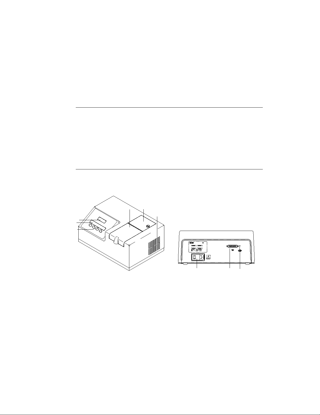
Fig. 2.1. View of VersaFluor Fluorometer System.
Instrument
1. Push Buttons Change menu and select options by pressing
buttons. Press a single button to perform the
action described on the menu display. The
function of each push button changes as the
menu changes.
2. Menu Display Displays various menus and options available.
3. Fluorescence Units Display Displays relative fluorescence units (RFU).
4. Sample Compartment Door Lift door to insert sample cuvette into the
cuvette holder.
5. Lamp Housing Door Lift door to replace the quartz halogen lamp.
2
1
4
789
5
6
2
3
Page 6

6. Fan Guard Exhaust air leaves cabinet through this opening.
7. Power Input Module and Power cord is connected to the power input
ON/OFF Switch. module. Instrument power switch.
8. Serial Output Port RS-232 connection to serial printer or com-
puter.
9. Menu LCD Contrast Adjust Carefully adjust the menu contrast using a
small screwdriver.
Sample Compartment
Fig. 2.2. Sample compartment top view.
1. Excitation Filter Holder Holds the excitation filter in place. The exci-
tation filter selects the wavelengthof thelight
which will illuminate the sample and excite
fluorescence.
2. Cuvette Holder Holds cuvette in place. The cuvette holder can
be removed by pressing the two tabs inward
and pulling upward.
3. Emission Filter Holder Holds the emission filter in place. The emis-
sion filter selects the emitted fluorescent light
that is detected by the fluorescence detector
circuitry.
3
Excitation
Emission
1
2
3
Page 7
Section 3
Installation
3.1 Envir onmental Requirements
To insure correct operation and stable performance over an extended period of time,
install the VersaFluor Fluorometer in a location which meets the following conditions:
• Room temperature between 20 and 35 °C. Not recommended for cold room use (4 °C).
• Not exposed to direct sunlight.
• Not subject to direct or continuous vibration.
• Not subject to intense magnetic or electromagnetic fields.
• Relative humidity between 0–95%.
• Area free from corrosive gases or other corrosive substances.
• Area with very little dust or other airborne particles.
• Allow a 10 cm minimum space around the instrument for proper air flow.
3.2 Power On and Initial Display
The VersaFluor Fluorometer is designed to operate at universal line voltage conditions of
100–240 VAC with an AC frequency of 50–60 Hz. With the power switch in the OFF position, plug the power cable into the power input module on the back of the instrument. To
insure positive grounding, plug the VersaFluor Fluorometer instrument into a three-prong
wire receptacle.
Turn on the power switch located on the power input module in the back lower right corner of the instrument. The menu display will show the following messages:
4
BIO-RAD
VERSAFLUOR™
BIO-RAD VER. 1.30
01/01/97 12:00:00
SAMPLE START 00001
RANGE SET
PRINT 00000 ZERO SETUP
Page 8

The first three screens are part of the instrument initialization and the fourth screen is the
main menu display. The VersaFluor Fluorometer instrument must warm-up for 20 minutes
prior to use. Measurements read prior to the warm-up time may cause irreproducible fluorescence readings.
3.3 Adjusting the LCD Contrast
The menu display LCD is factory adjusted for normal viewing. To change the contrast of
the menu display, locate the adjusting screw accessible from the back of the instrument
(Section 2.2). Inside the round hole above the label “LCD CONTRAST ADJUST” is the
adjusting potentiometer. Insert a small flat-bladed screwdriver into the round hole and carefully turn the adjusting screw to increase or decrease the menu display contrast.
3.4 Setting Up the VersaFluor Thermal Printer
The VersaFluor Thermal Printer, Model DPU-414 is ready for use with the VersaFluor
Fluorometer. The procedure for setting up the printer for the first time is described below.
Please refer to the Thermal Printer manual for more information.
Thermal Printer
1. Turn off the printer power.
2. Insert the DC plug on the AC adaptor into the power supply jack on the printer.
3. Plug the AC adaptor into an outlet.
4. Attach the serial cable adaptor to the serial cable.
5. Connect the 9-pin end of the serial cable to the serial port located on the back printer.
Connect the 25-pin end of the serial cable to the serial port located on the back of the
VersaFluor Fluorometer.
6. Load the thermal paper into the printer (Refer to the Printer manual).
7. The printer DIP switches must be set in the printer so that the VersaFluor Fluorometer can
communicate with the printer. Slide the power switch to ON while pressing the ONLINE
button. Release the ONLINE button and a list of the current settings will be printed.
8. The print out of the current settings is followed by the prompt:
"Continue? : Push On-line SW"
"Write? : Push paper feed SW"
Push the ONLINE button to continue.
9. Dip SW1 is printed, prompting the input of new settings for switch numbers 1–SW1. ON
can be set by pushing the ONLINE button once. OFF can be set by pushing the FEED but-
ton once.
Note: Always input either ON or OFF for every setting in order for switch number 1
through 8 because DIP SW Set Mode can not be canceled once it is initiated.
The setting is printed after the ONLINE or FEED button is pushed, confirming the new
setting. As soon as switch number 8 is set, the printer will prompt with "Continue?" or
"Write?" and steps 8 and 9 are repeated for DIP SW2 and DIP SW3. When switch
number 8 of DIP SW3 is set, the printer writes the settings to memory regardless of which
button is pushed.
Caution: Never turn the printer off while it is writing the new settings to memory.
5
Page 9

Below are the DIP switch settings to use with the VersaFluor Fluorometer. Please refer
to the printer manual for full descriptions of the DIP switch settings.
DIP SW1
Switch No. Action Setting
1 Press FEED (OFF)
2 Press ONLINE (ON)
3 Press ONLINE (ON)
4 Press FEED (OFF)
5 Press ONLINE (ON)
6 Press FEED (OFF)
7 Press ONLINE (ON)
8 Press ONLINE (ON)
DIP SW2
Switch No. Action Setting
1 Press ONLINE (ON)
2 Press ONLINE (ON)
3 Press ONLINE (ON)
4 Press ONLINE (ON)
5 Press ONLINE (ON)
6 Press ONLINE (ON)
7 Press ONLINE (ON)
8 Press FEED (OFF)
DIP SW3
Switch No. Action Setting
1 Press ONLINE (ON)
2 Press ONLINE (ON)
3 Press ONLINE (ON)
4 Press FEED (OFF)
5 Press FEED (OFF)
6 Press ONLINE (ON)
7 Press ONLINE (ON)
8 Press ONLINE (ON)
VersaFluor Fluorometer
The baud rate and flow control parameters is seton the VersaFluorFluorometer in order
to communicate with the thermal printer. Set the baud rate to 9600 and the flow control to
XON. See Section 4.8 for serial port function and parameters.
6
Page 10

Section 4
Introduction
4.1 Fluorometer System
The VersaFluor Fluorometer measures the concentration of various samples (analytes)
by fluorescence. By labeling a molecule with a fluorescent dye, the molecule can be accurately
quantitated by measuring the amount of fluorescence. Afluorescent molecule hasthe ability
to absorb energy at particular wavelengths and emit this energy at longer wavelengths.
Fluorescent dyes are classified by their excitation and emission wavelengths. Figure 4.1 shows
a typical excitation and emission spectrum. The excitation curve is at a shorter wavelength than
the emission curve. It is desirable to have no overlap between the two curves, insuring that all
the energy in the emission spectrum is a result of fluorescence.
The excitation and emission spectrums vary from dye to dye. The VersaFluor Fluorometer
has the capability to work with various dyes by using removable optical filters which select
for the specific excitation and emission wavelengths of a particular dye.
Fig. 4.1. Excitation and emission spectra of fluorescein.
For example, fluorescein has an excitation maxima at 490 nm and an emission maxima
at 520 nm (Figure 4.1). The EX490/10 excitation filter and the EM520/10 emission filter,
both of which have a 10 nm band pass, are used with fluorescein. The excitation filter allows
only light between 485 and 495 nm to pass throughthe sample. The emission filter removes
the excitation light and allows only the emitted light with a wavelength between 515 and 525 nm
to reach the detector.
The optical system of the VersaFluor Fluorometer is diagrammed in Figure 4.2. The
quartz halogen lamp emits light in the 350 nm to 900 nm range. Light emitted by the quartz
halogen lamp passes through a small aperture in the lamp housing before passing through the
excitation filter. The excitation filter allows only specific wavelengths of light to pass through.
450
500
550
600
400
Excitation
Emission
7
Wavelength (nm)
Excitation
400
450
500 550 600
Emission
Relative Fluorescence
Page 11

Fig. 4.2. Optical system.
Emitted fluorescent light from the cuvette is focused by the spherical mirror and passes
through the first aspheric lens. The emission filter allows light specific to the fluorescent compound to reach a second aspheric lens which directs the fluorescent light to the photodiode
detector. The detector system is a broad spectrum photodiode with analog circuitry to amplify the signal. The amplified analog signal is converted intoa digital signal and processed by
the controlling microprocessor before being sent to the fluorescence units display.The number in the Fluorescence Units Display (Section 2.2) represents the relative fluorescent units
(RFU).
8
PD detector
Emission filter
Aspheric lens
Spherical mirror
Excitation filter
Quartz light
Cuvette
Page 12

4.2 Operation Menu Overview
The VersaFluor Fluorometer is operated by selecting the menu of choice and pressing
one of the push buttons to perform a desired action.Each menu gives the user a different set
of choices. Figure 4.3 shows the menu flow diagram of the instrument.
Fig. 4.3. Menu flow diagram.
9
SET FULL RANGE: 00000
UP DO WN —> EXIT
RANGE SET
PRINT 00000 ZERO SETUP
A VRG GAIN
1 SEC LOW MORE EXIT
PRINT TIMED
SETUP SETUP MORE EXIT
BAUD CNTL PRINT
9600 X-ON SPACES EXIT
CLOCK LAMP SAMPLE
SETUP ON SET#1 EXIT
07/01/97 09:50:39
UP DOWN —> EXIT
TIMED SET
START INTVL EXIT
INTVL 01 SEC COUNT001
UP DOWN —> EXIT
TIMED COUNT 001
STOP
Page 13

4.3 Gain Function
Three gain settings are available in the VersaFluor Fluorometer instrument: LOW, MED,
and HIGH gain. There is a ten-fold difference between the gain settings. For example, if the
fluorometer shows a reading of 10,000 RFU on high gain, it will showapproximately 1,000
RFU on medium gain and approximately 100 RFU on low gain. The reading range of each
gain setting is between 0 and 19,999 RFU. If the reading is beyond the range of the instrument,
the fluorescence display will show 19,999.
A quick method for determiningwhich gainsetting touse is to first set the gain to MED
with the range at 00000. Place a sample with the highest concentration into the instrument
and read the fluorescence display. If the value is below 19,999, then use MED or HIGH gain.
If the value is 19,999, use LOW gain. Some trial and error work may be necessary to determine the correct gain setting to use.
The user can change gain setting at anytime during thesample measurement procedure.
It is recommended tocheck the zero of the instrument andre-zero if necessary, if the gain is
changed while reading samples. If the samples are read from the LOW gain setting to the
MED gain setting, the MED gain relative fluorescence units should be divided by 10 when
compared to the LOW gain setting units.
To change the gain setting, press the SETUP button in the main menu. Press the GAIN
button to select the gain setting (Figure 4.4).The gain can be toggled between LOW, MED,
and HIGH.
Figure 4.4 Gain setting menus.
4.4 Range Function
The fluorescence units shown on the fluorescence display can be set to a desired value.
The maximum value for the instrument is 19,999 RFU. Adjusting the range will change the
current maximum instrument reading to a different value set by the user. For example, a sample shows a reading of 4,000 RFU on MED gain, but the user would prefer to see 2,000.
Setting the range to 2,000 will change the current maximum reading to 2,000, and all future
values will also be scaled to the new range. It is important to set a new range value whenever a new fluorescent assay is being performed, because the fluorescent values will be scaled
according to the last sample used to set the range.
Setting the range higher than the amount of fluorescence detected by the fluorometer may
cause some fluctuation in the fluorescence units display. For example, a sample displays a
reading of 1,000 RFU on MED gain, but the range is set to 10,000. There could be a fluctuation in the display by as much as 10 units (background instrument noise times the range
factor of 10).
10
RANGE SET
PRINT 00000 ZERO SETUP
A VRG GAIN
1 SEC LOW MORE EXIT
Page 14

To set the range of the instrument to a desired value, place the highest concentration sample cuvette into the cuvette holder. Press RANGE on the main menu to access the range menu
(Figure 4.5). Use the arrow button (—>) to move the cursor along the five digit number. Use
the UP and DOWN buttons to raise and lower the value. Press the EXIT button to return to
the main menu. The fluorescence display will read the set value.
Figure 4.5 Setting the Range menus.
4.5 Set Zero Function
The VersaFluor Fluorometer can be zeroed by placing the baseline cuvette (cuvette with
baseline fluid) into the cuvette holder, closing the sample compartment lid, and pressing the
SET ZERO button on the main menu (Figure 4.6). The fluorescence display should read
0 ± 5 units after zeroing. Always zero the instrument with a range setting of 00000 before
setting the range value with the highest concentration sample.
Fig. 4.6. Set Zero menu.
4.6 Print A veraging Function
The menu item AVRG is used to apply averaging to the samples before printing. When
the PRINT button is pressed, the instrument takes sample readings for a specified period of
time and averages them. The menu item AVRG determines the duration of the averaging.
The average value is sent to the printer. When AVRG is set to 1 second, the instrument reads
1 second worth of samples and averages it. Changingthe AVRG to 2and 4 secondschanges
the length of time over which samples are averaged. The averaging function does not affect
the instrument's internal sample filtering process which automatically averages the data.
To access print averaging, press theSETUP button inthe mainmenu (Figure4.7). Press
the AVRG button to select the sample averaging time. Print averaging time can be toggled
between 1, 2, or 4 seconds.
11
RANGE SET
PRINT 00000 ZERO SETUP
RANGE SET
PRINT 00000 ZERO SETUP
SET FULL RANGE: 00000
UP DO WN —> EXIT
Page 15

Fig. 4.7. Print averaging menus.
4.7 Setting the Clock
The date and time information is sent to the printer or computer when the fluorometer is
turned on. This information is also sent to the serial port during timed or kinetic reading. Press
the CLOCKSETUP button from the third menu to access theclock setup parameters (Figure 4.8).
Use the arrow (—>) to scroll between the date and time. Use the UP and DOWN buttons to
raise and lower the values. Press EXIT to leave this menu.
Fig. 4.8. The date and time menus.
4.8 Serial P ort Functions
The VersaFluor Fluorometer has the ability to communicate with an external printer or
computer via the serial port located at the back of the instrument. The VersaFluor Fluorometer
sends the data to these peripherals as ASCII text. The VersaFluor Thermal Printer, Model
DPU-414 can be used with the VersaFluor Fluorometer (see Section 3.4 for printer set-up).
When connecting the VersaFluor to an external printer (not the VersaFluor printer) or computer, a "null-modem" cable should be used. The correct pin-out for this cable is described on
the next page. Check the printer or computer for the correct serial port connector end (male
or female).
12
RANGE SET
PRINT 00000 ZERO SETUP
AVRG GAIN
1 SEC LOW MORE EXIT
CLOCK LAMP SAMPLE
SETUP ON SET#1 EXIT
07/01/97 09:50:39
UP DOWN —> EXIT
Page 16

DB25F Connector Signal and DB25M Connector
to VersaFluor (Male) Direction to serial device
2 TX--> 3
3 <-- RX 2
4 RTS - - > 5
5 <-- CTS 4
7 Common 7
20 DTR - - > 20
(other pins are open
in VersaFluor)
The serial port can be reconfigured by using print setup command (Figure 4.9). The three
parameters that can be configured are the baud rate, flow control, and the data spacing. To
access the print parameters, press SETUP in the main menu, then press MORE in the second
menu, and finally press PRINT SETUP in the third menu (Figure 4.3). The serial port baud
rate can be changed by pressing the BAUD button. The baud rates settings are NONE, 1200,
2400, 4800, or 9600. The data flow control can be set to XON or R/CTS by pressing the
CNTL button. The print spacing can be set to NONE, SPACES, or TABS. Refer to Section
3.4 for setting up the VersaFluor thermal printer. For other printers or computers, please refer
to the instrument's instruction manual for correct settings.
Fig. 4.9. Serial port menus.
4.9 Kinetic Readings
The VersaFluor Fluorometer supports kinetic studies via timed data sampling. The user
can set the number of readings and the intervals between readings. Each time a reading is
taken, the value is shown on the fluorescence display. The value and date/time information is
also sent to the serial port for printing or downloading to a computer database.
To access the kinetic or timed reading parameters, press SETUP in the main menu, then
press MORE in the second menu, and finally press TIMED SETUP (Figure 4.3). To set the
timed reading parameters press the SET INTVL button. The timed interval can be in seconds
(SEC) or minutes (MIN). The number of readings can be set in the COUNT area. Use the
arrow button (—>) to scroll between time and counts. Use the UP and DOWN buttons to
raise or lower each value. The example in Figure 4.10 shows that readings will occur every
5 seconds, 15 times (a total of 75 seconds). Press the EXIT button when the timed reading
parameters are set.
13
PRINT TIMED
SETUP SETUP MORE EXIT
BAUD CNTL PRINT
9600 X-ON SPACES EXIT
Page 17

Fig. 4.10. Timed reading menus.
To start the timed readings, press the TIMED START button. An active timed reading
menu will appear. To stop the readings at any time, press the TIMED STOP button. This
screen will remain active until allthe readings arefinished. TheCOUNT valuewill increase
sequentially as the readings progress. Each time areading is taken, the relative fluorescence
units will be displayed and sent to the serial port. When the last reading is taken, the menu display will automatically return to the TIMED START and SET INTVL screen.
4.10 Lamp ON/OFF
The lamp on the fluorometer can be turned on or off. To access this function, press SETUP
in the main menu, then press MORE in the second menu, and finally press MORE in the third
menu (Figure 4.3). Press the LAMP button to turn thelamp ON or OFF (Figure 4.11). Press
EXIT to leave this menu. After turning the lamp back on, let the instrument warm up for at
least 10 minutes.
Fig. 4.11. Lamp ON/OFF menu.
4.11 Resetting the Print Sample Number
When the PRINT button is pushed, the fluorometer sends the fluorescence data and a
sample number to the printer. This sample number increases sequentially every time the
PRINT button is pushed. The SAMPLE SET#1 button must be pushed to reset the sample
number to one. To access this function, press SETUP in the main menu, then press MORE in
the second menu, and finally press MORE in the third menu (Figure 4.3). Press the SAMPLE SET#1 button to reset the sample number (Figure 4.12). The menu will display 00001,
indicating the sample number has been reset. Press EXIT to leave this menu.
14
PRINT TIMED
SETUP SETUP MORE EXIT
TIMED SET
START INTVL EXIT
INTVL 01 SEC COUNT001
UP DOWN —> EXIT
TIMED COUNT 001
STOP
CLOCK LAMP SAMPLE
SETUP ON SET#1 EXIT
Page 18

Fig. 4.12. Sample number reset menu.
Section 5
Operating Instructions
5.1 Quick Guide Procedure
This section describes the typical procedure for taking fluorescence measurements. Menu
options are described in Section 4. A typical sample measurement requires five steps:
Note: The instrument should warm up for at least 20 minutes before taking any read-
ings.
1. Selection and insertion oftwo optical filters.
Insert the emission and excitation filters into the VersaFluor Fluorometer.
2. Set the gain.
Press the SETUP button on the main menu and set the gain to LOW, MED, or HIGH.
3. Zero the instrument.
Set the range to 00000 by pressing theRANGE button. Adjustthe range to00000. Press
EXIT. Place the baseline sample cuvette in the cuvette chamber and press the SET ZERO
button. When blinking stops the fluorescence display should read 0 ± 5. If not, re-zero the
instrument by pressing the SET ZERO button.
4. Set the range.
Set the range by placing a cuvette containing the highest concentration standard in the
cuvette holder and closing the sample compartment lid. Wait approximately 10 seconds
for the detector to adjust to the light conditions. Press the RANGE button. Adjust the
range to the desired setting. The maximum setting is 19,999 RFU. Press EXIT.
5. Measure the sample.
Place a sample cuvette in the cuvette holder and close sample compartment lid. Wait
approximately 10 seconds for the detector to adjust to the light conditions. Record or
print the RFU value in the fluorescence display. Read all remaining samples.
15
CLOCK LAMP SAMPLE
SETUP ON SET#1 EXIT
Page 19

5.2 Instrument Parameter Set-Up
1. The VersaFluor Fluorometer instrument must warm up for 20 minutes prior to use. If the
instrument is not fully warmed up, the reading may be irreproducible.
2. Select an excitation and emission filter which are to be inserted in the filter holders. Orient
the filters so that the notched groove on the filter holder faces the cuvette holder.
Caution: Use filters which are tailored to the sample being measured. Using incorrect
filters will greatly degrade the accuracy of the fluorescence measurement.
3. Press the SETUP button on the main menu to access the print averaging and gain set-
tings.
4. Press the AVRG to select the print averaging time (1, 2, or 4 seconds).
5. Press GAIN to select the gain setting (LOW, MED, or HIGH). Then press EXIT to return
to the main menu.
6. Add the standards, unknown samples, and blanks to the disposable cuvettes.
7. Follow the sample measurement guidelines below to insure accurate results:
• Warm up the instrument for at least 20 minutes.
• Always use calibrated pipets to insure accurate pipetting.
• Mix standards and sample completely by using a disposable transfer pipet.
• Remove any air bubbles in the cuvettes.
• Hold fluorometer cuvettes by the upper edges since the cuvetteshave four optically
clear sides.
• Clean the cuvette sides with a lint-free tissue.
• Read all standards and samples at ambient temperature.
• While taking a reading, keep the samples in the fluorometer only. This helps reduce
sample photobleaching.
5.3 Setting Up a Standard Curve
The range should be set on the fluorometer with a known standard and a fluorescent dye.
Depending on the protocol used, a single-point or multi-point standard curve is required.
1. Set the range of the instrument to 00000 by pressing the RANGE button. Adjust the range
to 00000. Press EXIT.
2. Zero the instrument by placing the baseline cuvette (blank) in the cuvette holder and closing sample compartment lid. Wait approximately 10 seconds for the detector to adjust to
the light conditions. Press the SET ZERO button; when blinking stops, read the fluorescence display. If fluorescence display is0±5,theinstrument is zeroed. If not, re-zero
the instrument by pressing the SET ZERO button.
3. Set the range of the instrument by placing the highest concentration standard cuvette in
the cuvette holder and closing the sample compartment lid. Press the RANGE button.
Adjust the range to the desired setting. The maximum setting is 19,999 RFU. Press EXIT.
The fluorescence display should read the set range value. Read or printthe RFU number
in the fluorescence display. Remove the highest concentration standard cuvette.
16
Page 20

Optional: The zero of the instrument can be rechecked by placing the baseline cuvette
(blank) in the cuvette holder. Wait approximately 10 seconds for the detector to adjust to
the light conditions. If the instrument needs to be re-zeroed, press the SET ZERO button.
When blinking stops, the fluorescence display should read0±5.
4. For multiple standard samples, read the remaining samples. Wait approximately 10 seconds for the detector to adjust to the light conditions. Read or print the RFU number in the
fluorescence display. The value shown on the fluorescence display is a measure of the difference between the baseline sample and the highest concentration standard.
Note: Fluorescence measurements can be made continuously. It is not necessary to zero
the instrument before each measurement unless the baseline conditions change. Check
the zero of the instrument with the baseline fluid (blank) when switching between gain settings.
5.4 Reading Unknown Samples
1. Place a cuvette with an unknown sample in the cuvette holder and close the sample compartment lid. Wait approximately 10 seconds for the detector to adjust to the light conditions. Read or print the RFU number in the fluorescence display.
2. Repeat for all remaining unknown samples.
Note: Fluorescence measurements can be made continuously. It is not necessary to zero
the instrument before each measurement unless the baseline conditions change. Check
the zero of the instrument with the baseline fluid (blank) when switching between gain settings.
3. The sample concentrations can be determined by comparing its RFU values with the standard(s).
17
Page 21

Section 6
Troubleshooting
6.1 Troubleshooting Table
Problem Cause Solution
No display with poweron Burned out fuse Replace fuse.
No RFU values withsamples Lamp OFF Insure that the lampis ON.
Lamp burned out Replace lamp.
Thermal fuse tripped CallBio-Rad Service.
Lamp OFF with powerON Lamp OFF Insure that thelamp is ON.
Thermal fuse tripped CallBio-Rad Service.
Negative values Readingsbelow set 1. Zero the instrument with the
zero (blank) range set to 00000. Set the range
with the highest concentration
standard.
2. Zero between gain settings.
Readings fluctuate Interference in light 1. Check that there are noscratches
path on the cuvette.
2. Check that there are no particulates floating in thecuvette.
3. Wipe the cuvette walls with a lintfree tissue.
4. The instrument reading may
fluctuate somewhat at high gain
setting with low concentration
samples.
5. Insure that the gain and range
have been set properly (Sections
4.3 and 4.4).
6.2 Performance Check—Internal Diagnostics
Under normal conditions, the VersaFluor Fluorometer will operate for many years with
minimal maintenance. If the instrument is operating, but a problem is suspected,run the performance check.
1. The VersaFluor Fluorometer instrument can be tested by internal diagnostics which ver-
ify correct operation of the electronics. With the sample compartment door closed, the
internal diagnostics are accessed by holding down any of the four buttons while turning
on the instrument. The diagnostic display below will be shown.
18
DIAGNOSTICS
***** MED .06FS LAMP
Page 22

2. The three right-hand push buttons are used to operate the diagnostics. Starting from the
right, the first push button turns the lamp on or off, the second selects the voltage to be
inserted into the instrument, and the third selects the amplifier gain. The diagnostics are
restricted to testing the analog electronics and digital processing, which includes post
amplification, gain changes, A/D conversion, digital filtering, and the LCD display. One
of three fixed voltages is inserted into the analog amplifiers just following the photodiode
(PD) detector and preamplifier.
3. Two different values can be changed throughthe diagnostic routines:the voltage setting
and the gain setting of the analog amplifier. The voltage can be set to either 0, .006FS, or
.06FS. The analog amplifier gain can be set to LOW, MED, or HIGH.
4. All diagnostic testing is performed with the lamp turned off. The lamp can be turned on
or off by pressing the button marked LAMP. To determine if the lamp is on or off, inspect
the cuvette holder. If the lamp is on, light will be visible inside the cuvette holder.
5. With the voltage set to 0, the reading on the LCD is the background noise present in the
analog electronics, it will be different for each gain setting. The other two voltages (.006FS
and .06FS V) are typical ofwhat theelectronics wouldexperience duringnormal opera-
tion.
6. To determine correct instrument operation, record all nine values and subtract the respec-
tive noise (0 reading) from the .006FS and the .06FS readings. Use the table below to
record the values.
7. The resulting six numbers will be used to determine if the instrument electronics and
digital processing are working correctly. The following table lists the expected values
and the tolerance of each value.
Gain .006FS .06FS
LOW 12±5 125±50
MED 125 ± 25 1,250 ± 250
HIGH 1,250 ± 200 12,500 ± 2,000
8. If the calculated values are within the ranges given above, the analog electronics and
digital processing is operating correctly. If the instrument fails this test, contact your local
Bio-Rad service representative.
19
LOW Gain
0
.006FS .06FS
MED Gain
HIGH Gain
-
-
--
--
=
=
=
=
==
Page 23

Section 7
Maintenance
7.1 Fuse Replacement
1. The fuses for the VersaFluor Fluorometer instrument are located inside the power input
module on the back of the instrument (Figure 2.1). Turn the instrument off and unplug the
power cord before attempting to replace the fuses.
Fig. 7.1. Fuse replacement.
2. To remove the fuses; carefully pry the cover open using a small screwdriver. Inside the
power input module, there are two fuse carriers each containinga5x20mmfuse.
Carefully slide the fuse carriers out and remove the burned-out fuses. Replace with new
fuses.
Warning: Replace fuses with the current rating of 1.6 ampere, slow blow, T-type.
3. With new fuses in place, slide the fuse carriers into the power input module and snap the
cover shut.
7.2 Lamp Replacement
1. Turn the instrument off and remove the power cord. Allow the lamp to cool for 5–10
minutes.
Fig. 7.2. Lamp replacement.
2. Locate the fastener on the lamp cover. Carefully rotate the fastener 1/4 turn using a coin or
screwdriver. Open the lamp cover. Thelamp islocated atthe bottomof the lamp housing.
20
Page 24

3. The lamp base has two prongs whichpush into asocket at theback of thelamp housing.
To remove the lamp, grasp it firmly at the base and pull it straight up.
Caution: Never touch the lamp with bare fingers. Quartz halogen lamps can be destroyed
by the oil from skin. Use a tissue or soft cloth to remove the lamp. If the lamp is con-
taminated with oil or dirt, clean with a dry soft cloth.
4. To install a new lamp, slide the new lamp into the socket on the base of the lamp hous-
ing. Close the lamp cover and push the fastener to lock.
5. Turn the instrument on and inspect the sample compartment to ensure that the lamp is
lit.
7.3 Cleaning Up a Fluid Spill
The fluid handling system, an integral part of the VersaFluor Fluorometer, provides easy
cleanup in case of spills. By using a special purpose optical bench and a drain pan, the
VersaFluor Fluorometer is able to minimize the delay caused by fluid spills (< 2 ml). If a spill
is apparent, no electrical hazard is created because the fluid is contained by the fluid handling
system, a collection of components designed to hold and manage fluid spills.
1. Turn the instrument off and unplug the power cord.
2. To clean up spills, open the sample compartment and remove the cuvette holder by press-
ing the two tabs inward and pulling upward. Remove the two filters.
3. Using a clean cotton swab or cloth, dry all three cavities: the excitation filter slot, the
emission filter slot, and the cuvette holder cavity. Insure the glass lenses and mirror are
dry. Do not apply excessive pressure on the lenses and mirror while cleaning. Dry the
entire cuvette holder and filters.
4. Replace the cuvette holder and filters into the sample compartment.
5. Since fluid can accumulate in the drain pan, two drainage tubes are provided to allow
overflow fluid to exit the instrument. Theoverflow fluid willdrain outthe bottom ofthe
instrument. Clean up any fluid under the instrument. A few drops of fluid may continue
to leak out the bottom of the instrument after a spill. Check the area under the instrument
periodically for any signs of spills.
21
Page 25

Section 8
Filters for Fluorescent Protocols
Excitation Catalog Emission Catalog
Application Filters Number Filters Number
DNA Quant (Hoechst 33258) EX 360/40 (340–380 nm) 170-2420 EM 460/10 (455–465 nm) 170-2421
ß-Galactosidase (MUG) EX 360/40 (340–380 nm) 170-2420 EM 460/10 (455–465 nm) 170-2421
ß-Glucuronidase (MUGluc) EX 360/40 (340–380 nm) 170-2420 EM 460/10 (455–465 nm) 170-2421
Apopain (Z-DEVD-AFC) EX 360/40 (340–380 nm) 170-2420 EM 520/10 (515–525 nm) 170-2424
pH indicator (BCECF) EX 490/10 (485–495 nm) 170-2422 EM 520/10 (515–525 nm) 170-2424
Calcium indicator (Fluo-3) EX 490/10 (485–495 nm) 170-2422 EM 520/10 (515–525 nm) 170-2424
DNA Quant (PicoGreen™) EX 480/20 (470–490 nm) 170-2427 EM 520/10 (515–525 nm) 170-2424
Oligo Quant (OliGreen™) EX 480/20 (470–490 nm) 170-2427 EM 520/10 (515–525 nm) 170-2424
Protein Quant (NanoOrange™) EX 480/20 (470–490 nm) 170-2427 EM 590/10 (585–595 nm) 170-2425
Fluorescein EX 490/10 (485–495 nm) 170-2422 EM 520/10 (515–525 nm) 170-2424
Ethidium Bromide EX 510/10 (505–515 nm) 170-2423 EM 620/10 (615–625 nm) 170-2426
RNA Quant (RiboGreen™) EX 490/10 (485–495 nm) 170-2422 EM 520/10 (515–525 nm) 170-2424
Section 9
Specifications
Instrument
Light source 20 watts incandescent quartz halogen 350 nm to 900 nm.
The quartz halogen lamp is rated to operate for 2000 hours.
Sensing device Photodiode
Optical filters Excitation 1” diameterwith holder
Emission 1” diameter withholder
Sample source Cuvette: 12.5 mm x 12.5mm (outside dimension)
Sensitivity selection Three settings: LOW, MED,and HIGH.
Approximate factor of 10between each setting.
Dynamic range Greater than 5 orders using all three sensitivity selec-
tions.
Printer output RS-232, Serial
AC Power Requirement
AC power input 100–240VAC 50–60 Hz, 1.6 A slow-blow fuse
Size and Weight
Overall size 23 cm (L) x33 cm (W) x 15cm (H)
Shipping weight 4 kg
Environmental Requirements
Storage environment 0 to 70°C, humidity 0–95% (non-condensing)
Operating environment 20 to 35 °C,humidity 0–95%
Regulatory
Meets the requirements of: EN61010-1, EN50082-1, EN55011/03
22
Page 26

Section 10
Systems, Accessories, and Reagents for VersaFluor
Fluorometer
Catalog
Number Product Description
VersaFluor Fluorometer
170-2402 VersaFluor Fluorometer 100/120/220, includes a standard cuvette
holder, 100 standard disposable cuvettes, and oneexcitation and one
emission filter
170-2403 VersaFluor Fluorometer 120V, includes everythinglistedin 170-2402
plus a 120V thermal printer and cable
170-2404 VersaFluor Fluorometer 100V, includes everythinglistedin 170-2402
plus a 100V thermal printer and cable
Optical Excitation Filters
170-2420 EX360/40 (340–380 nm)
170-2427 EX480/20 (470–490 nm)
170-2422 EX490/10 (485–495 nm)
170-2423 EX510/10 (505–515 nm)
Optical Emission Filters
170-2421 EM460/10 (455–465 nm)
170-2424 EM520/10 (515–525 nm)
170-2425 EM590/10 (585–595 nm)
170-2426 EM620/10 (615–625 nm)
VersaFluor Thermal Printer
170-2409 100V VersaFluor Thermal Printer, with cable and 100V AC adaptor
170-2410 120V VersaFluor Thermal Printer, with cable and 120V AC adaptor
170-2411 220V VersaFluor Thermal Printer, with cable and 220V AC adaptor
170-2412 Thermal Printer Paper, 10 rolls
170-2413 Thermal Printer Universal Battery pack
VersaFluor Disposable Cuvettes
170-2415 Standard Cuvette, 12.5 x 12.5mm (outside dimension) 4-sidedopti-
cally clear disposable, polycarbonate, 3.5 ml, 100
Accessories
170-2406 Standard Cuvette Holder
170-2430 Quartz Halogen Replacement Light Bulb
170-2450 Optical Filter Storage Case
23
Page 27

Catalog
Number Product Description
Fluorescent Reagents
170-2480 Fluorescent DNA Quantitation Kit, Hoechst 33258
170-2481 Hoechst 33258 (bisbenzimide) Dye
170-3130 FluorAce™ Apopain Assay Kit
170-3150 FluorAce™ ß-Galactosidase Reporter Assay Kit
170-3151 FluorAce™ ß-Glucuronidase Reporter Assay Kit
170-3141 Fluo-3 Fluorescent Calcium Indicator Kit
170-3142 Fluo-3 AM
170-4143 Fluo-3 K+ Salt
170-4134 4-Br-A23187
170-3145 Calcium Calibration Buffer
170-3146 pH Indicator (BCECF-AM)
170-3147 pH Indicator (BCECF Acid)
PicoGreen, OliGreen, NanoOrange, and RiboGreen are trademarks of Molecular Probes Inc.
24
Page 28

S
cience
eb site
a
a
4
k
dFrance
ael
yJap
ea
ds
9
Swede
8
0
US/EG
A
Bio-R
ad
aboratories
M1702401 Rev B
L
Life
Group
ulletin 0000
W
Alsoin: Australi
Brazil
Denmar
Isr
Kor
TheNetherlan
n Ph. 46(0)8-55 51 27 00, Fx. 46(0)8-55 51 27 80SwitzerlandPh. 061-717-9555,Fx. 061-717-9550 United Kingdom Ph. 0800-181134,Fx. 01442-25911
Rev
Ital
Finlan
Austri
Belgium Ph. 09-385 55 11,Fx. 09-385 65 5
Ph. 01 47 95 69 65,Fx. 01 47 41 9133
an
Ph. 47-23-38-41-30,Fx. 47-23-38-41-3
00-000 0000 Sig 120
 Loading...