

Page 1
VersaDoc
Imaging System
User’s Manual
for Catalog Numbers
1708010, 1708011, 1708030
1708031, 1708140, 1708141, 1708050, 1708051
Copyright 2001 Bio-Rad Laboratories Inc.
Manual Part Number 4000183 Rev. E
Page 2

Page 3

Welcome
Dear Customer,
On behalf of Bio-Rad Laboratories, we would like to thank you for investing in the
VersaDoc
high quality imaging.
One of the best ways to familiarize yourself with the capabilities of your new VersaDoc
system is to read this manual. In it, you will learn how to set up the system and operate
all hardware components. It is also recommended that you read the accompanying
software manual to familiarize yourself with general acquisition functions and data
analysis. After reading this manual, please keep it close to your system so that it can be
conveniently referred to.
Your VersaDoc system is protected by a comprehensive instrument warranty agreement.
Please read this manual thoroughly, so that you fully understand the coverage provided
and are aware of your rights and responsibilities. One of the responsibilities of system
ownership is regular maintenance. Following the maintenance instructions provided with
this manual will help to keep your system and peripherals functioning optimally and will
protect your investment. Please also keep in mind that Bio-Rad offers a range of
comprehensive service agreements that can be tailored to meet your specific needs.
Bio-Rad Laboratories is dedicated to your total satisfaction and would be pleased to
answer any questions that you may have.
How to Contact Bio-Rad Laboratories
In the United States you can reach Bio-Rad Laboratories at the following numbers:
For general information
Toll free: 1-800- 4BIORAD
1-800-424-6723
Fax: 1-510-741-5802
email: lsg.techserv.us@bio-rad.com
For service or technical assistance
Toll free: 1-800-424-6723
Fax: 1-510-741-5802
For information concerning Bio-Rad Laboratories and its products, visit our Worldwide
Web site at http://www.bio-rad.com
Imaging System and we are sure that it will provide you with many years of
Page 4

Page 5

Table of Contents
Section 1 General Information PAGE #
1.1 About this Manual 1-1
1.2 Safety Information 1-2
1.2.1 General Cautions 1-2
1.2.2 General Warnings 1-2
1.2.3 Power Safety Information 1-3
1.2.4 UV Safety Information 1-3
Section 2 Introduction
2.1 System Capabilities 2-1
2.2 System Description 2-1
2.3 Mechanical Description 2-3
2.4 Overview of the Imaging Process 2-4
2.5 Illumination Flat Fielding 2-4
Section 3 System Installation
3.1 Operating Requirements 3-1
3.1.1 System Location 3-1
3.1.2 Power Requirements 3-1
3.1.3 Host Computer Recommendations 3-2
3.2 System Setup 3-2
3.2.1 Unpacking 3-3
3.2.2 Shipping Check 3-3
3.2.3 Coupling the Camera Module to the Enclosure 3-5
3.2.4 Installing VersaDoc 1000,3000,4000 3-6
3.2.5 Installing VersaDoc 5000 3-8
3.2.6 Installing the Epi Illumination Modules 3-12
3.2.7 Electrical and Communication Connections 3-13
3.2.8 Installing Filters 3-21
3.2.9 Installing the Lens 3-23
Section 4 System Operation
4.1 Starting the VersaDoc 4-1
4.2 Overview of Operating Steps 4-1
4.3 Detailed Operating Procedures 4-2
4.3.1 Opening the Acquisition Window 4-2
4.3.2 Selecting the Application 4-3
4.3.3 Placing the Sample in the Imaging Chamber 4-3
4.3.4 Lens Selection and Setup 4-4
4.3.5 Aperture Adjustment 4-5
4.3.6 Zoom Adjustment 4-5
4.3.7 Focus Adjustment 4-6
4.3.8 Exposure Time 4-6
4.3.9 Acquiring the Image 4-7
Page 6

Section 5 Care and Maintenance PAGE #
5.1 General Maintenance 5-1
5.1.1 Cleaning the Sample Platen 5-1
5.1.2 Cleaning the UV Transilluminator Filter Glass 5-1
5.1.3 Cleaning the Lens 5-2
5.1.4 Cleaning the Emission Filters 5-2
5.2 Replacing lamps in Illumination Sources 5-2
5.2.1 Replacing lamps in the Transilluminator Module 5-2
5.2.2 Replacing Lamps in the Epi- illumination Module 5-4
5.3 Lens and Filter Storage 5-5
Section 6 Troubleshooting & Technical Information
6.1 Problem Solving Guide 6-1
6.2 Technical Service 6-3
6.3 VersaDoc System Specifications 6-4
6.4 Warranty Information 6-6
6.5 Glossary of Terms 6-7
6.6 Parts List 6-8
Page 7

Section 1
General Information
1.1 About this Manual
This manual provides instructions for installing, operating and maintaining the
VersaDoc Imaging System. This manual uses certain conventions to
facilitate understanding of the text material and to assist operators in using the
VersaDoc system.
Conventions
Left and right sides of the instrument are as viewed from the front (operator’s
position) unless otherwise stated.
Commands that are typed in from the keyboard are referred to as <xxxx>, and
when you are expected to use the mouse pointer to activate a button it will be
referred to as CLICK xxxx. When you are expected to click and drag the
mouse to a certain item it will be referred to as SELECT xxxx.
Notes, Cautions and Warnings
Notes, cautions and warnings are used to highlight certain operating
procedures and recommendations.
A note indicates a special procedure, an exception to normal operation or
something else of specific interest to the reader. Notes are preceded by the
word “Note” in italics.
A caution precedes an operational step that could damage the instrument or
destroy data unless the operator takes certain precautions. Cautions are
located in the main text, are preceded by a Caution: statement and are
accompanied by a “Caution Symbol” in the left margin.
A warning precedes an operating procedure that could cause injury to the
operator if not followed correctly. Warnings are located in the main text, are
preceded by a Warning: statement and are accompanied by a “Warning
Symbol” in the left margin.
User’s Manual • 1-1
Page 8
1.2 Safety Information
This instrument is meant for Laboratory use only and should not be
used in any other way or manner that is not specified in this Manual.
Your safety and the safety of others are very important to us. To help you
make informed decisions about safety, we have provided comprehensive
operating procedures and safety information in this manual and on labels
affixed to instrumentation. This information will alert you to any potential
hazards. It is the user's responsibility to take time and read and understand
the Safety Information and put it to the best use for a Safe operation of the
system.
1.2.1 General Cautions
Caution: Ensure that all of the systems ventilation openings are free of
interference. Excessive heat build up in the instrument may effect performance
or cause operational failure.
Caution: With the exception of cleaning or replacing light bulbs, refer all
servicing to qualified Bio-Rad personnel or their agents. If you experience
technical difficulties with the instrument contact Bio-Rad to schedule a service
appointment. The instrument should not be modified or altered in any way.
Alteration of this instrument voids the manufacturer’s warranty and may create a
potential safety hazard for the user.
Caution: Bio-Rad is not responsible for any injury or damage caused by the use
of this instrument for purposes other than that for which it is intended or by the
modification of this instrument when not performed by qualified Bio-Rad
personnel or an authorized agent.
1.2.2 General Warnings
Warning: This instrument must be connected to an appropriate AC voltage
outlet that is properly grounded.
Warning: There are hazardous voltages inside the rear panel of the
VersaDoc. Do not remove the cover to the Electronics back panel when the
instrument is connected to AC power.
Warning: Do not defeat any instrument interlocks; they are designed to
prevent user injury.
Warning: The
you have purchased. Exercise caution when lifting the instrument. It is
recommended that at least two persons lift the instrument. Lift the instrument
by the bottom plate. Never lift the instrument by opening at the top which is
the plastic camera mounting plate because this will cause light leaks and
damage the camera mounting plate.
VersaDoc weighs 44 kg (96 lbs.) depending on which camera
User’s Manual • 1-2
Page 9
1.2.3 Power Safety Information
The VersaDoc contains high voltage circuits. The user must disconnect the
power cord prior to opening the rear access panel, or removing the lamp
modules for bulb replacement.
WARNING: It is mandatory for the users to power down the system and
disconnect the AC mains from the unit before performing any disassembly or
repair to the instrument.
The VersaDoc system is designed and certified to meet EN61010 Safety and
EN61326 +A1 Electromagnetic Compliance requirements, which are
internationally accepted safety standards. Certified products are safe to use
when operated in accordance with the instruction manual. This safety
certification does not extend to uncertified equipment or accessories, even
when connected to the VersaDoc system.
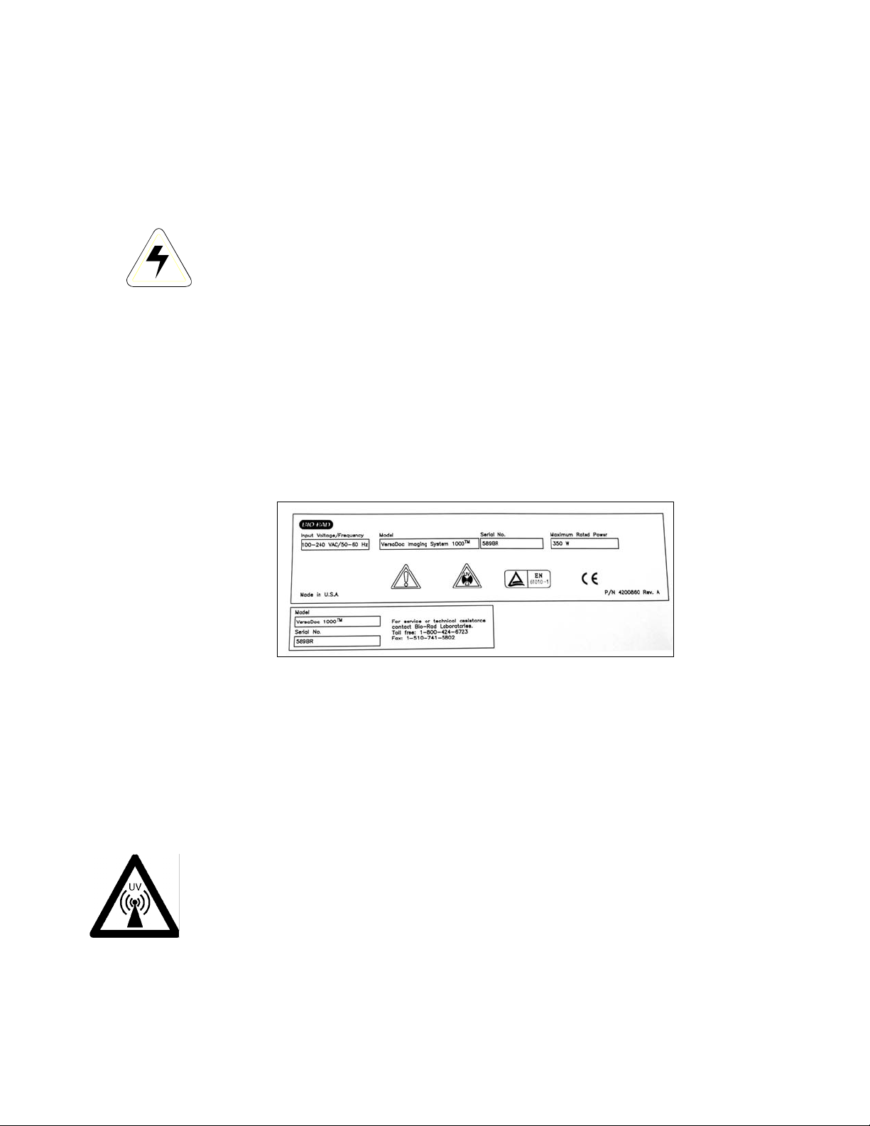
Figure 1.1 shows the serial number certification label, which is found on the
rear panel of the VersaDoc system. This label provides manufacturing data
and safety compliance information about the instrument.
Figure 1.1
For easy customer access the instrument serial number information located at
two places in your system.
1. On the rear of the instrument
2. Inside the main door
1.2.4 UV Safety Information
This instrument uses a powerful source of UV radiation and may cause
damage to unprotected eyes and skin. The VersaDoc provides safety
interlocks on both the main door and the sliding UV transilluminator module
to protect the user from accidental UV exposure. A plastic UV shield is
provided for convenience, however, it may not be adequate to protect you
from accidental UV exposure. You must use additional personal UV
protection like UV protective eyeglasses, gowns, gloves etc.
User’s Manual • 1-3
Page 10

Warning: Do not remove the rear access panel when power is supplied to the
instrument or defeat the UV safety interlock. Attempting to operate the unit
with the cover removed may damage the instrument and expose the operator
to UV radiation.
Warning: Use of controls or adjustments, or performance of procedures other
than those specified herein may result in exposure to hazardous UV radiation.
How to Contact Bio-Rad Laboratories
In the United States you can reach Bio-Rad Laboratories at the
following numbers:
For general information
Toll free: 1-800- 4BIORAD
1-800-424-6723
Fax: 1-510-741-5802
email: lsg.techserv.us@bio-rad.com
For service or technical support
Toll free: 1-800-424-6723
Fax: 1-510-741-5802
For information concerning Bio-Rad Laboratories and its
products, visit our Worldwide Web site at http://www.bio-
rad.com
User’s Manual • 1-4
Page 11
Section 2
Introduction
2.1 VersaDoc System Capabilities
The VersaDoc Imaging System is a quantitative imaging system for capturing high
resolution digital images from single and multi-color fluorescence,
chemiluminescence, chemifluorescence and colorimetric samples. Using cooled CCD
technology in combination with a unique ultraviolet illumination mechanism and a
highly efficient optical design, the VersaDoc offers researchers the sensitivity,
uniformity, flexibility and dynamic range they require for the analysis of
electrophoretic and microplate samples, among others. With direct imaging and
automated acquisition, this system can increase laboratory throughput and eliminate
the need for chemiluminescent detection using x-ray film.
Flexible Design:
The VersaDoc Imaging system has a very flexible design. The light tight enclosure
can accommodate any of the offered camera modules. The user has the option to
upgrade to any of the four standard models. The standard VersaDoc comes with
every feature included. The VersaDoc 1000L, 3000L, 4000L and 5000L come with
light tight enclosure, camera and filter wheel. The user has the option to choose a
variety of illumination modules to fit their needs. This allows customization of the
system by selecting the type of camera and the type of illumination you need.
Additionally, all systems can be upgraded.
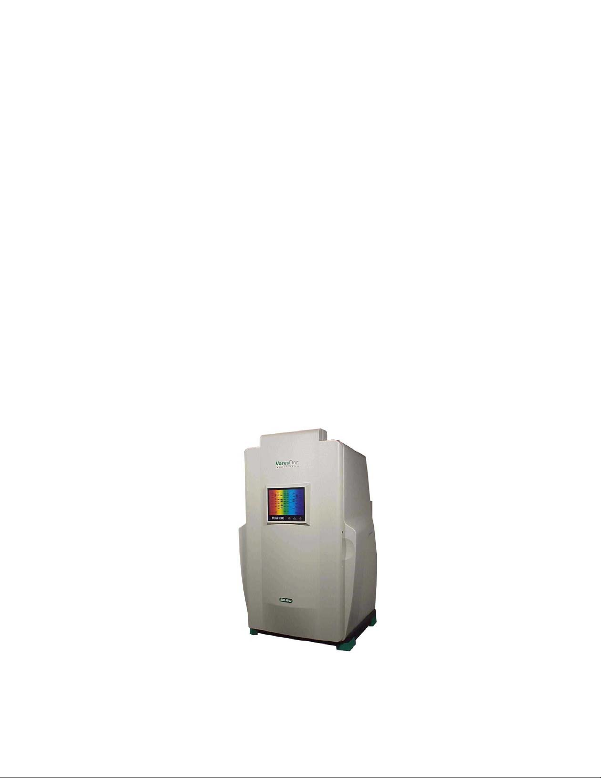
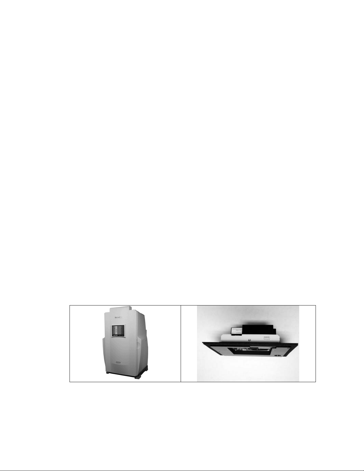
2.2 System Description
Figure. 2.1 The VersaDoc Imaging System.
The VersaDoc combines several key components into a unique, powerful and fully
integrated image analysis system:
User’s Manual • 2-1
Page 12

(1) Cooled CCD Technology
The VersaDoc system uses cooled CCD technology for image capture and improves
image quality by reducing background noise and enhancing the signal to noise ratio.
This is particularly important for low light chemiluminescence and fluorescence
applications.
(2) Unique Trans and Epi-illumination Source
The VersaDoc system incorporates unique trans and epi-illumination modules for
both UV and white light excitation. This provides high-sensitivity imaging of a variety
of fluorescent, chemifluorescent and colorimetric samples. The broad bandwidth UV
excitation (290-365 nm) supports the detection of a broad range of fluorescent dyes
in contrast to the limited number of dyes, which may be excited using a single
wavelength visible laser.
(3) Interchangeable Lens
The
VersaDoc is supplied with two standard lenses. One zoom and one 50 mm
mono-focal.
Depending upon which VersaDoc system has been purchased, either a 20-40 mm or
the 28-80 mm zoom lens will be included. This zoom lens is ideal for most
fluorescence and colorimetric applications.
The 50 mm, f1.4 fixed lens has a high light collection efficiency and is the lens
recommended for all chemiluminescence applications.
You may purchase an optional 105 mm lens that can be used for imaging small
samples at high resolution. The VersaDoc will accommodate most Nikon f-mount
lenses with a minimum operating distance (MOD) of 0.65 m.
It is highly recommended that lenses be purchased through Bio-Rad, as some Nikon
lenses require modification before they can be inserted into the filter wheel housing.
Use of an unmodified lens may result in damage to either the instrument or lens
mount.
(4) Emission Filters
An eight-position emission filter wheel has been incorporated into the optical design
of the VersaDoc to permit multi-color image discrimination and the detection of many
different fluorescent dyes. The VersaDoc is supplied with four standard filters. Filter
#1 (520LP-Long Pass) is optimized for single color detection of ethidium bromide,
DNAStar, SYBR
Red, SYPRO
Green, SYBR Gold, Radiant Red, SYPRO Orange, SYPRO
Ruby, Texas Red, Cy2, Cy3 and most fluorescein and rhodamine
derivatives. Filters #2 (530BP60) and #3 (610LP) are for the independent detection of
green (fluorescein) and red (Texas Red) fluorescence in multiple colored samples.
These filters effectively support multiplexing analysis for increased sample throughput
and more accurate molecular weight determination. Filter #4 is a clear filter that can
be used for white light applications. Filter positions (Filter #6 #7 & #8) are available to
users for the installation of application specific custom filters. Filter position #5 should
be left vacant for the optimized collection of chemiluminescent samples.
User’s Manual • 2-2
Page 13
(5) Quantity One 1-D Analysis Software
The Quantity One software permits user-friendly control of the VersaDoc Imaging
System and accurate analysis of the captured image or data. Quantity One is
designed for operation in a Windows or Macintosh environment and supports fully
automated application-based image acquisition.
NOTE: Windows NT does not support USB therefore all WINDOWS NT based systems must use a
Serial Communications port.
The Quantity One package allows substantial flexibility in the presentation of captured
images and provides many tools for data analysis. These include molecular weight
determination, automated lane and band finding, accurate concentration analysis,
VNTR and differential display studies and colony counting. Please refer to the
Quantity One instruction manual for a full description of this software package.
2.3 Mechanical Description
The VersaDoc Imaging System is a modular system and it consists of the following
main hardware components. See figure 2.2.
1. The light tight enclosure, which integrates the sliding UV transillumination module,
two epi-illumination modules, chemiluminescence tray, access to the filter wheel,
lenses and all the electronics needed for controlling the lights and filterwheel.
2. The camera module, which integrates the cooled CCD camera.
3. Depending on which model of VersaDoc you have (1000, 3000, 4000 or 5000),
you will have the corresponding camera module but the light tight enclosure will
be the same.
4. VersaDoc is also available in a "LITE" versions (1000L, 3000L, 4000L or 5000L)
where no illumination sources are included. The unit is offered with a light tight
enclosure and a camera with a filter wheel. All illumination modules, lenses, and
filters are customized for your specific needs.
Light Tight Enclosure Camera Module
Figure. 2.2. Components of the VersaDoc system.
User’s Manual • 2-3
Page 14

2.4 Overview of the Imaging Process
The acquisition and analysis of image data using VersaDoc technology is a simple
five-part process.
Step 1: Samples to be imaged are placed on the transilluminator module.
Step 2: The appropriate imaging method is selected in the VersaDoc acquisition
window of Quantity One.
Step 3: The sample is aligned using the positioning template in the Quantity One
acquisition window.
Step 4: If required, the imaging lens is zoomed and focused onto the sample to obtain
the highest quality image.
Step 5: The desired collection time for an aperture setting of the lens is selected and
the image is captured. In cases where Flat Fielding is selected, a reference image is
also acquired (see below). Once the sample image is collected and saved, this
Image can then be reviewed and analyzed using the appropriate tools bundled in the
Bio-Rad software package. Please refer to the software manual for further details.
2.5 Illumination Flat Fielding:
A uniform images are essential for quantitative analysis. The VersaDoc Imaging
System features a proprietary algorithm that allows elimination of image nonuniformities caused by lens, illumination source. Optimization of the image uniformity
is made possible via the Illumination Flat Fielding function in the image acquisition
portion of the software.
NOTE: This feature is only for imaging applications that utilize a UV or white
light transillumination source.
Illumination Flat Fielding when using the UV transilluminator:
The software takes an initial image and then prompts the user to remove the sample
and to place the VersaDoc Fluorescent Reference Plate provided with your system
on the UV Transilluminator.
Illumination Flat Fielding when using the white light conversion screen:
The software will prompt the user at the beginning of the image acquisition to place
the VersaDoc white light conversion screen on the UV transilluminator. The sample is
placed on the conversion screen; an initial image is taken. The software then
prompts the user to remove the sample from the VersaDoc white light conversion
screen and then finishes image acquisition.
User’s Manual • 2-4
Page 15
Section 3
System Installation
3.1 Operating Requirements
3.1.1 System Location
The VersaDoc system should be located in an area that is free of excessive dust or
moisture, strong magnetic fields or ionizing radiation. It is also highly recommended that the
ambient temperature be stable and within the range of 10°C to 28°C (21°C is optimal) and
that the relative humidity not exceed 70%, non-condensing.
Warning: Care should be taken when lifting and moving the VersaDoc system
to avoid personal injury. It is recommended that two people, one on each side
of the instrument lift the VersaDoc enclosure from the bottom.
The VersaDoc should be placed on a level bench top with a minimum depth of 70 cm and a
height clearance of 180 cm, where there is adequate ventilation for the system’s cooling
fans to operate. The system’s feet allow enough clearance for easy removal of your hands
from underneath the instrument once the system has been placed on the bench.
In placing the VersaDoc, users should also allow for easy access to the main power switch,
which is located on the lower right hand side of the system’s rear panel. The instrument
should be placed where there is adequate room to insert the samples into the front of the
enclosure and where it can be easily connected to the host computer. The maximum
distance between the host computer and the instrument should be two meters. (instrument
is supplied with cables long enough for such distances).
Note: The host computer should be located at a workstation that minimizes
operator fatigue.
3.1.2 Power Requirements
The VersaDoc system and its host computer should be connected to a stable grounded
power outlet on a circuit free of electrical noise. In addition, a high quality electrical surge
suppressor/line filter with a 10 Amp or higher rating should be used to avoid damage from
AC fluctuations. Only a grounded 3-pin power cord should be used to connect power.
The VersaDoc is designed for operation at an input voltage of 110-240 VAC, at 50-60 Hz.
Deviation from these operating voltages can lead to slower cooling and heating
process with your deeply cooled CCD camera.
User's Manual • 3-1
Page 16

3.1.3 Host Computer Recommendations
The VersaDoc system is capable of producing large image files of high resolution to easily
handle such large files. A powerful computer is required.
Please refer to your software manual for detailed host computer system and software
requirements. If the computer is not purchased from Bio-Rad, systems compatibility is the
responsibility of the user. Please check with your local Bio-Rad office regarding
compatibility for your specific brand of computer.
3.2 System Setup
There are 3 main phases in the installation of the VersaDoc system:
1. The components are delivered to your laboratory.
2. The system is installed by a trained Bio-Rad representative.
3. Users are trained on the operation of the VersaDoc and accompanying peripherals and
software by a Bio-Rad representative.
The following steps for setup of the VersaDoc requires approximately two hours.
Prepare the VersaDoc hardware:
1. Unpack components
2. Perform shipping check
3. Install the camera module
4. Install the transilluminator module and epi-illumination modules
5. Connect system cables
6. Install emission filters
7. Install lens
8. Connect electrical and host computer communication cables
9. Power up the instrument
Each of these steps is detailed in the following sections.
User's Manual • 3-2
Page 17
3.2.1 Unpacking the VersaDoc System Components
With the exception of operating software, VersaDoc components are shipped in palletsupported boxes. Unpack the components by following the steps listed below:
1. Cut the two steel straps supporting the main instrument package.
2. Remove the top cardboard lid. Remove other packaging materials and secondary boxes
from the top.
3. Slide the outer sleeve off the box vertically. The VersaDoc enclosure can be found
within the box.
4. With the assistance of a helper, remove the VersaDoc from the box. Grip the bottom of
the enclosure on both sides (do not lift the instrument by the front door or electronics
area) and place it on the floor for the next step in the setup procedure. When placing
the enclosure allow clear access to the rear panel for connection of the appropriate
cables.
Warning: Get a helper; a single person should not attempt to lift the VersaDoc.
Warning: To avoid back injury, always bend your knees and keep a straight
back when lifting heavy objects.
Caution: Do not supply power to the instrument until the VersaDoc system has
been set up using the following installation procedures.
5. Open all the other boxes and carefully remove all the items.
6. Perform a shipping check to confirm that the system has been supplied complete.
3.2.2 Shipping Check
During the unpacking process inspect all shipping containers to ensure that you have
received all ordered items and that no boxes are damaged. If items are either missing
or damaged, this should be noted at the time of installation so that it can be immediately
reported to both the shipping company and Bio-Rad manufacturing.
The Quantity One acquisition and analysis software is supplied in a separate box.
User's Manual • 3-3
Page 18
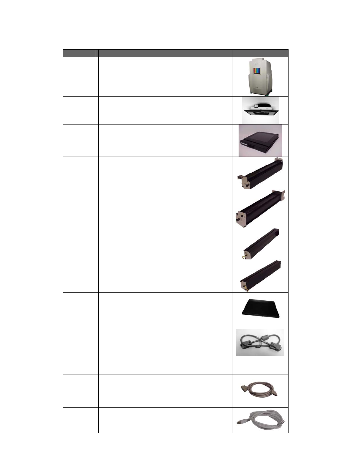
The VersaDoc hardware should arrive complete with the following items:
Quantity Item Photo
1 VersaDoc light tight enclosure
1 VersaDoc camera module (Shown Model
1000 camera module, model 3000, 4000
and 5000 are shown later in this section)
1 VersaDoc transilluminator module (already
installed inside the light tight enclosure)
1 Pair of UV epiilluminator modules
1 Pair of White epi illuminator Modules
1 Sample/chemi tray
1 Camera power cable (VersaDoc 1000 and
4000 only)
Or
Fan assembly power cable (VersaDoc 5000
only)
1 Camera AIA interface cable
1 Serial/USB communication cable
User's Manual • 3-4
Page 19

Quantity Item
1 Sample Holder Kit
1 VersaDoc Fluorescent Reference Plate
1 PCI Digitizing Card
1 White Light Conversion Screen (Optional)
5 Filters (530DF70, 520LP, 610LP, Clear, 660Cutoff)
2 Lenses (20-40mm Zoom, 50mm Fixed)*
2 Lenses (28-80mm Zoom, 50mm Fixed)* *
1 Lens and Filter Cleaning Kit
1 Focusing Target
1 Power Cord
1 Instruction Manual
1 Camera Specification File (CD)
1 58mm-52mm Step Down Ring**
1 Warranty Card
* These are provided with VersaDoc 1000 model only
** These are provided with VersaDoc 3000, 4000 and 5000 models
NOTE: Please retain all packaging materials for future transport of the
VersaDoc system. Additional charges will be assessed if packaging is not
available for instrument warranty shipping.
3.2.3 Coupling the Camera Module to the enclosure:
This applies to all camera modules (VersaDoc 1000, 3000, 4000 and 5000). Follow
the procedure outlined below to mount the camera module to the enclosure.
1. Leave the enclosure on the floor for easy access to the camera mount.
2. Correctly position the camera module on the camera mount located at the top of
the enclosure such that the three holes in the camera module adapter plate will
match the three standoffs located in the filter wheel assembly in the camera
mounting plate.
NOTE: The camera module should sit completely flat and square on the
surface of the Enclosure to avoid light leaks
3. Using the 3 cap-head screws and the 9/64” hex key (included), secure the
camera adapter plate to the standoffs. Carefully tighten the screws evenly to
form proper light seal. See figure 3.1 for details.
.
User's Manual • 3-5
Page 20

Three cap head screws to secure the camera to the filter wheel assembly
Three Standoffs
Figure 3.1.
3.2.4 Installing VersaDoc 1000, 3000 ,4000.
Connecting the Cables to the Camera Module:
This procedure applies to the Versa Doc 1000 and 3000 and 4000 systems.
Connecting the camera power cable:
Camera power cord has a DIN connector on each end. The cable with a 9- pin DIN
connector is for the VersaDoc 1000 and 4000 cameras and the cable with a 15-pin
DIN for the VersaDoc 3000. See Figure 3.2
NOTE: VersaDoc 3000 systems with Enclosures that are serial number XXXBR 300 or greater come with
a separate power supply for the camera . This power supply already includes a power cable for the
VersaDoc 3000 camera. VersaDoc 3000 systems
Connect this cable between the camera power socket on the camera module and
the enclosure. Picture shown below is for enclosures with serial numbers below
XXXBR0300:
VersaDoc 1000 and 4000 Camera Power
Connector
9 pin camera power connector on top side
of the rear panel
User's Manual • 3-6
VersaDoc 3000 Camera Power connector
15 pin camera power connector on top side
of the rear panel
Page 21

If your enclosure has a serial number above XXXBR300 then connection should be made
per pictures shown below:
VersaDoc 1000 and 4000
Camera Power Connector
Camera Power connector on
top side of the rear panel
VersaDoc 3000 Camera Power
connector
Camera Power connector on
the cable from camera power
supply
Figure 3.2
NOTE: The VersaDoc 4000 camera must be connected to the same power port as the
VersaDoc 1000
.
Connecting the AIA CABLE:
For VersaDoc 1000 and 3000 and 4000 only:
1. Connect the AIA cable (Part #800-0247) to the AIA port on the camera (See Figure 3.4).
Push the cable to the connector such that it clicks and snaps in place properly.
AIA CONNECTORS
ON EACH END OF
THE CABLE
VERSADOC 1000, 4000
CAMERA AIA CONNECTOR
Figure 3.4
User's Manual • 3-7
VERSADOC 3000 CAMERA
AIA CONNECTOR
Page 22

2. The other end of the AIA cable will be connected to the PCI digitizing card that will be
installed in the PC after software installation as shown later in this procedure.
NOTE: The steps describing the installation procedure for the PCI digitizing card
follows later in this procedure.
3.2.5 Installing VersaDoc 5000
Connecting the cables to the camera module:
1. The VersaDoc 5000 camera module comes with a camera controller unit (CEU) and
Camera Controller Unit
(CEU)
a controller cable. See figure 3.6 below :
Camera Module
Camera Controller Cable
Figure 3.6
2. Couple the VersaDoc 5000 camera module to the enclosure as shown in the section
3.2.3 above. See Figure 3.1 for details.
3. Next connect the CEU to the camera.
Caution: The default voltage setting on the camera power supply
module is 120 VAC. You must follow the instructions below to make
sure proper voltage selection is made and fuse is used for you AC
voltage environment.
Caution: The VersaDoc 5000 camera module has a “BLUE” plug
installed on the connector on the camera. This plug must not be
removed until the module is installed to the enclosure and the
camera controller unit is ready to be connected to the Camera.
Setting the VersaDoc 5000 System Power Supply Voltage (If required):
1. Familiarize yourself with the camera controller unit [CEU]. See Figures 3.7a, b and c
below:
User's Manual • 3-8
Page 23

Figure 3.7a Figure 3.7b
AIA Connector on CEU
Camera
Controller Cable
Connector
Figure 3.7c
2. A small white tab on the AC inlet located on the rear panel indicates the voltage
setting on your camera controller unit. See Figure 3.8
Insert a small screw driver and pull out the tab
White plastic stub
shows the current
voltage setting.
Make sure it
matches with the
local voltage.
3. Pull out the small tab near the AC inlet using a small screwdriver. See Figure 3.8
4. The TAB holds a fuse completely remove it. This will expose a tiny PCB located in a
tiny slot as shown in Figure 3.9
Figure 3.8
User's Manual • 3-9
Page 24

Small PCB in a tiny
f
slot. This side of the
PCB has letters on
this side.
Fuse holder.
Figure 3.9
5. Using the plastic stub on the PCB select the orientation of the board so that the
desired voltage numbers and arrow point towards the socket for the board. The tab
on the inside surface of the stub must match with the notch on the tiny PCB See
Figure 3.10a and 3.10b:
Plastic stub that
shows through
the hole
indicating the
selected voltage
100 VOLT and arrow must
point inward. Insert the
board back into the socket
with the letters facing the
right side
Notch on each side
of the PCB,
Plastic stub that
shows through the
hole indicating the
selected voltage.
NOTCH on each side o
the PCB,
6. Now reinstall the tiny PCB back into it’s socket such that the numbers on it face
towards the right side (towards the Fuse holder inlet)
Setting for 100 volt operation
Figure 3.10 a
230 VOLT and arrow must
point inward. Insert the
board back into the
socket with the letters
230 Volt setting
Figure 3.10b
7. Next remove the Phillips screw that holds the fuse holder and turn the holder around
so that the two 1 amp fuses face towards the socket. See Figure 3.11
User's Manual • 3-10
Page 25

Remove Screw
Figure 3.11
8. Push the tab until it locks in its socket.
9. Check again to make sure that the plastic stub indicates the desired voltage
selection
Connecting the VersaDoc 5000 Camera and CEU Cables
:
1. Connect the AIA cable to the connector labeled AIA on the CEU connector panel.
The other end of this cable will be connected to the PCI digitizing card in your PC.
2. Remove the “BLUE” shorting plug from the camera and connect the camera control
cable between the camera and the CEU. See figure 3.12
Fan Assembly
Power
Connector
Blue Shorting Plug
VesaDoc 5000 Camera Module Blue Shorting plug
Figure 3.12
3. Connect the AC power cord to the AC inlet on the CEU but do not power up the
CEU yet.
4. For units serial number below XXXBR300: Connect the fan power cable from the
fan assembly (5000 models only) to the DB9 power connector located at the top
surface of the electronics module. See picture 3.13A
5. For units with serial number xxxBR300 or higher: Connect the fan power cable
from the fan assembly (5000 models only) to the DB9 power connector
located on the side of the electronics module. Once connected, the system cable
User's Manual • 3-11
Page 26

connections will look similar to the ones shown in Figure 3.13 A or B depending on
th eserial number of the enclosure you may have.
Fig 3.13A
Fig 3.13 B
Fan Cable
Figure 3.13
3.2.6 Installing the Epi modules:
1. Remove the access panel mounted on the ballast panel by unthreading the two
thumbscrews.
Thumb
screws on the
ballast panel
Figure 3.14a
2. If not connected already, connect the transilluminator cable to the connector labeled
“UV TRANSILLUMINATOR” located on the ballast panel on interior rear wall of the
enclosure.
3. To install the epi UV and white modules first install the epi UV module by inserting
the two prongs on its end plate to the slots located at the back wall.
4. Secure the module using the captive screw by lining up the front side of the module
with the hole located in the wall of the instrument. (See Figure 3.14b).
5. Now connect the cable from the epi UV module to the appropriate connector on the
ballast assembly.
User's Manual • 3-12
Page 27

Threaded insert
for captive screw
on the EPI UV
module
Slots for EPI UV
Tongue and Groove mechanism to
hang EPI WHITE from EPI UV.
Figure 3.14b Figure 3.14c
6. Next attach the epi white module to the epi UV module by locking in the tongue and
groove located at the outer top edges of each module. (See figure 3.14c)
7. Now secure the epi white module to the epi UV module using the latch and screw
mechanism located at the front plate of the modules. See Figure 3.15
Figure 3.15
8. Next connect the cable from the epi white module to the appropriate connector on
the ballast assembly.
9. Re-install the access panel to the ballast panel.
NOTE: The plugs for each illumination module are keyed and cannot be interchanged.
Each plug will snap together only to the appropriate socket.
3.2.7 Electrical and Communication Connections
Power
The power entry module of the VersaDoc system is configured for operation at 100/120
VAC, 60 Hz or 220-260 VAC, 50 Hz. After checking that the system’s power switch is
turned off, insert an approved power cord into the power entry module located on the
bottom right of rear panel of the unit. See Figure 3.16
User's Manual • 3-13
Page 28

Warning: This instrument must be connected to an appropriate AC
voltage mains outlet that is properly grounded.
Warning: There are hazardous voltages inside the rear panel of the
VersaDoc. Do not remove the cover to the electronics back panel when
the instrument is connected to AC power.
Power entry module at the
bottom right of the rear
panel
Figure 3.16
VersaDoc Connections:
The VersaDoc is connected to the host computer via a Serial or USB
interface and an AIA interface.
One each of the Serial and USB port is located on the rear right side of the
unit. Use the supplied USB or Serial Cable to connect the PC to the
VersaDoc.
Caution: To prevent damage to the hardware, all instruments must be
turned off before attempting to connect (or disconnect) the unit to the
host computer.
Upon insertion of the Serial or USB cable into the VersaDoc, the Serial or USB
port the PC will automatically select operation and sense the presence of
VersaDoc.
NOTE: Do not turn ON the power to the VersaDoc (and CEU in case of VersaDoc
5000) yet!
Power entry module
User's Manual • 3-14
Page 29

Connecting the AIA Cable to the Computer:
To do this, two things must happen:
i. The software must be installation on the PC which will control this system
ii. The PCI Digitizing card must be installed into the PC where the AIA cable is
to be connected
.
Software Installation:
Please follow the instructions below to install the PC or Mac software for VersaDoc
system:
NOTE: Do not install the PCI card into the PC yet. First install the drivers as
shown below and then install the PCI Card.
PC: based VersaDoc systems:
a. Insert “The Discovery Series” software CD into the CD ROM drive of the PC.
It will go into AUTO RUN mode and the following window will open:
b. Click on “NEXT” the following window will open:
User's Manual • 3-15
Page 30

c. Click on the arrow next to ChemiDoc XRS/VersaDoc drivers to get installer
options. See picture below:
d. If you are installing the drivers on local drive select appropriate option by
scrolling down as shown in the picture below. Click on “NEXT”:
User's Manual • 3-16
Page 31

e. Drivers will be copied to the appropriate location on your hard drive and at the
completion the following window will appear.
f. Click on “FINISH” and the system will shut down. At this time, install the PCI
card into the system and REBOOT the system.
g. As the system re-boots and Windows 2000/XP starts it will find the PCI card and
go through a “FOUND NEW HARDWARE” installation routine and find the
drivers that were just installed.
NOTE: In case the PCI card was installed before the software then go to
section 6 for software troubleshooting. In case of the MAC systems it does
not matter if the PCI Card is installed before or after installing the software
and drivers.
Mac based VersaDoc systems
NOTE: This procedure applies to both Mac OS 9.xx and OS 10.xx based systems.
h. Insert “The Discovery Series” software CD into the CD ROM drive of the MAC.
Installer will open and offer choices.
User's Manual • 3-17
Page 32

i. Choose custom install from the pulldown menu in this window and click on
“INSTALL” The following window will open.
Depending upon the Imaging device you are installing, click on the desired
j.
Imager you want to install and then click on “Install”. The drivers will get loaded
and at the completion of the installation the following window will open
User's Manual • 3-18
Page 33

k. Click on “RESTART” so that the system will start and will now restart.
l. Please read the “README” file before using the system
Installing the PCI digitizing card to the PC:
Caution: Ensure that the VersaDoc system is turned off before Installing the
digitizing card and AIA cable.
1. Now install the digitizing card into a PCI slot in your computer and secure it with
appropriate screw. See Figure 3.17
PCI digitizing card PCI slot inside the PC
Figure 3.17
2. Connect the camera to the digitizing card with the AIA cable. Do not power up the
PC/MAC yet. See section 3.2.9 for powering up the PC.
User's Manual • 3-19
Page 34

3. With both Serial or USB and AIA cables connected, your system will appear as
shown in one of the figures 3.18 a~e below:
:
Fan Cable
Power Cable
AIA Cable
Control
Cable
Serial/USB
Figure 3.18a
VersaDoc 1000, 3000 and 4000 Systems under
Serial # xxxBR300
AIA Cable
Power Cable
Serial/USB
Power Supply
Serial/USB
AIA Cable
Figure 3.18b
VersaDoc 5000 System under Serial # xxxBR300
Fan Cable
Control
Cable
Serial/USB
AIA Cable
Figure 3.18c
VersaDoc 3000 Systems starting Serial # xxxBR300
Camera Power Cable
Serial/USB
Figure 3.18e
VersaDoc 1000 and 4000 Systems starting Serial # xxxBR300
User's Manual • 3-20
Figure 3.18d
VersaDoc 5000 System starting Serial # xxxBR300
AIA Cable
Page 35

Power On Sequence
Normally, the VersaDoc system should be switched on for 30 seconds before
The host computer is powered up. This protocol is required for the computer to
recognize the VersaDoc as a peripheral device.
1. Power up the VersaDoc system first.
2. Also power up the power supply block in case of the VersaDoc 3000 or CEU in case
of the VersaDoc 5000 system.
3. Power up the PC/Mac second.
4. In case of a PC, the VersaDoc system is detected via USB connection. A new
window will indicate that a new USB device has been found.
5. Proceed to the next step to complete the installation
3.2.8 Installing Filters
The VersaDoc is supplied with three emission filters and one clear filter. These
must be installed in the 8-position filter wheel before use. These filters are:
#1 520LP (Long Pass) Used for most single color fluorescent stains and
labels.
#2 530BP (Band Pass) Used for detection of green signal (FITC etc.) in
multi-color fluorescence experiments
#3 610LP (Long Pass) Used for detection of red signals (Texas Red
etc.) in multi- color fluorescence experiments
#4 Clear Used for system focus and some colorimetric
applications.
To install the filters follow the procedure below (Figure 3.19):
1. Ensure that all power and communication cables are connected and that the
VersaDoc system is turned on.
NOTE: Do not power up the PC or MAC yet.
2. Open the main door. This will expose the camera, filter assembly, filter advance
button and the lens mount assembly.
3. Loosen the left side screw of the filter wheel cover and remove the right side
thumbscrew completely by fully unscrewing it. The cover can now be rotated
downward to expose the filter wheel.
4. Push the filter advance button until filter position #1 is in the center front position.
The #1 label should be clearly visible on both sides of the filter slot.
User's Manual • 3-21
Page 36

5. Remove filter #1 from its packaging and check that it is clean, free of dust,
fingerprints and scratches. If the filter is dirty it should be cleaned with the materials
provided in the lens and filter cleaning kit.
6. Holding the filter by the numbered tab with the number in the correct orientation,
carefully slide the filter into the open filter wheel position.
7. Repeat steps 4-5 for the remaining filters (#2, #3, #4)
8. Replace the filter wheel cover and hand-tighten both captive thumbscrews.
9. Close the main door firmly. The filter wheel will automatically reset to the home
position and is now ready for operation.
NOTE: The above procedure can also be used for the installation of custom filters.
Open filter wheel access panel and
rotate it downward as shown
Unpack and carefully install filter 1
Figure 3.19
Advance to position 1
Make sure that filter 1 is all the way
in its slot and positioned straight.
User's Manual • 3-22
Page 37

3.2.9 Installing the Lens
The VersaDoc system is supplied with two standard lenses, a flexible zoom
lens and a high NA 50-mm lens with improved collection efficiency
Zoom Lens for fluorescence and colorimetric imaging
The Tamron zoom lens is recommended for use with all fluorescence and colorimetric
applications and for high intensity chemiluminescence experiments. The zoom
capabilities of this lens supports the imaging of small and large samples. The zoom lens
is not a high numerical aperture (NA) lens and should not be used for low intensity
chemiluminescence experiments.
High Numerical Aperture Lens for Chemiluminescence Imaging
The Nikon 50 mm high NA (f/1.4) lens is designed for optimized light collection
efficiency and should be used for all low intensity chemiluminescence experiments. The
lens can also be used for collecting typical fluorescence and colorimetric images. The
chemiluminescence sample tray may be used to move the sample closer to the camera.
Infrared Cutoff Filter
When performing any fluorescence experiments it is required that the 660 nm infrared
cut-off filter that is supplied with the VersaDoc is installed on the front of collecting lens.
This filter will block any infrared signal that will be generated by the UV bulbs,
substantially reducing image background and improving sensitivity. This filter is not
required for chemiluminescence experiments and should not be used when collecting
low intensity chemiluminescence signals, as it will reduce the amount of signal
collected.
Lens Use Recommendation
For optimal image acquisition, it is recommended that the zoom lens with 660 nm cut-off
filter installed is used for all fluorescence and colorimetric applications. In
chemiluminescence experiments, the 50 mm fixed lens with no cut-off filter is
recommended.
Zoom Lens Installation
To correctly install the zoom lens. Follow the procedure outlined below (Figure
3.20):
1. Remove the lens from its packaging and retain the packaging for future storage.
2. Remove the front lens cap and install the 58mm-52mm step down ring, then the
660 short pass (SP) filter onto the lens.
User's Manual • 3-23
Page 38

3. Remove the protective cover from the lens mount (rear of lens) and check that
the lens is clean. If the lens is dirty it should be cleaned with the materials
provided in the lens and filter cleaning kit.
4. Open the door to the main door and position the lens so that the white line on its
mount matches the white mark on the base (right hand side) of the camera
assembly.
5. Insert the mount of the lens into the base of the camera assembly and turn the
lens counter clockwise (to the left) until you hear it click. The white mark and
setting indicators on the lens should now be directly in front of you.
6. The lens in now locked into position and the lens cap and protective platen
cover can be removed.
Figure 3.20. Steps in zoom lens installation.
High Sensitivity 50 mm Lens Installation
To correctly install the 50 mm high NA lens, follow the procedure outlined below
(Figure 3.21):
1. Remove the lens from its packaging and retain the packaging for future storage.
2. Remove the protective cover from the lens mount (rear of lens) and check that the
lens is clean, free of dust, fingerprints and scratches. If the lens is dirty it should be
cleaned with the materials provided in the lens and filter cleaning kit.
3. Open the door to the main door and position the lens so that the white line and dot
on its mount matches the white mark on the base of the camera assembly.
4. Insert the mount of the lens into the base of the camera assembly and turn the lens
clockwise (to the left) until you hear it click. The main white line and lens settings are
directly in front of you.
User's Manual • 3-24
Page 39

Figure 3.21. Steps in 50 mm lens installation.
5. The lens in now locked into position and the lens cap and protective platen cover
can be removed.
Lens Removal
To remove the lens from the camera housing follow the procedure outlined below
(Figure 3.22):
1. Place the lens cap on lens
2. Hold the lens firmly with your left hand throughout the remainder or the removal process
so that it cannot be dropped accidentally.
Caution: Accidentally dropping the lens could break the UV
transilluminator platen or white light conversion screen. Replacement
of such a broken platen or white light conversion screen is not covered
by warranty or service contract.
3. Depress the red release button on the base of the camera housing. This is located to
the rear, right-hand side of the lens.
4. Rotate the lens in a clockwise direction (to the right) to release it from the housing.
5. Pull the lens down and remove it from the filter wheel assembly.
6. Replace the mount cover. If the lens is not being used for some time it is recommended
that it be stored in its original packaging.
User's Manual • 3-25
Page 40

Proceed to section 4.
Figure 3.22. Steps in lens removal.
User's Manual • 3-26
Page 41

Section 4
Operating the VersaDoc
4.1 Starting the VersaDoc System
Both the VersaDoc and the camera module must be connected to the computer prior to
using the VersaDoc system.
To turn on the VersaDoc press the power switch located on the right-hand side of the rear
panel of the instrument. The green LED on the front will illuminate indicating that the
system is ready and to confirm that power is being supplied and all the internal light
modules are functioning properly. The start up initialization process takes approximately 30
seconds. After this time has elapsed the host computer can be turned on. At this time you
can also power up the power supply or CEU if you have a VersaDoc 3000 or 5000 system.
Note: If the LED indicator fails to illuminate and the instrument is inoperative, check that all power cables
are firmly attached and that power is being supplied to the unit. If the unit still remains inoperative or the
VersaDoc acquisition window cannot be opened on the host computer, please contact the Bio-Rad
Technical Service Department for assistance.
The VersaDoc should be switched on at least 30 seconds before the host computer, to
allow for complete initialization. If the VersaDoc is not fully operational before the computer
is turned on, the system will not be recognized as an attached Serial/USB device and the
camera may not be recognized by the digitizing card thus you will not be able to
communicate with the VersaDoc from the Quantity One acquisition window.
For best imaging results it is recommended that the VersaDoc be allowed to warm-up for
10 minutes before use.
4.2 Overview of Operational Steps
The user will typically complete the following series of steps when acquiring an image using
the VersaDoc:
1. Start the program and open the acquisition window
2. Select the desired application
3. Place the sample on transilluminator platen, converter screen or chemi tray as the case
may be and optimize its position
4. Focus
5. Adjust the lens aperture and zoom
6. Readjust focus if required
7. Select the exposure (acquisition) time
8. Acquire the image
User’s Manual 4-1
Page 42

4.3 Detailed Operating Procedures
4.3.1 Opening the Acquisition Window
After starting your computer, open the Quantity One acquisition and analysis program by
double clicking on the Quantity One icon.
From the FILE menu select VERSADOC to open the instruments acquisition window. The
following window will open on the screen.
Note: If the computer cannot establish communications with the VersaDoc a message will indicate this and
give the user the option of entering a simulation mode.
Figure. 4.1. VersaDoc acquisition screen in Quantity One.
User's Manual • 4-2
Page 43

4.3.2 Selecting the Application
The Quantity One program uses an application-oriented format to simplify user selection of
collection parameters. To correctly set the parameters for collection, simply click the
SELECT button in Step I (Figure 4.1) and identify the application name matching your
sample type. For detailed acquisition instructions please refer to the Quantity One software
instruction manual.
4.3.3 Placing Samples in the Imaging Chamber
The VersaDoc can accommodate a variety of sample types and sizes. The sample stage is
25 X 25 cm. This configuration supports the acquisition of smaller areas of interest within
very large samples. The imaging area is liquid sealed so wet samples may be placed
directly into the imaging chamber on the UV transilluminator platen. With wet samples you
will find it convenient to use the sample holders provided with your VersaDoc system.
These sample holders have suction cups that hold the sample in place and keep it from
sliding around on the polished glass surface.
Caution: The sample stage area is resistant to most research chemicals but may be
damaged by extended contact with strong acid solutions and organic solvents. When
imaging samples exposed to these chemicals, users should wash the sample stage with
water and wipe dry immediately after imaging.
Samples should be placed in the VersaDoc instrument following the steps outlined below:
1. Open the main door.
2. Visually check that the sample platen is clean. If not, clean using an optical cleaning
solution and a soft lint-free towel or lens cleaning tissue.
3. From the VersaDoc acquisition window select the POSITION function in Step II (Figure
4.1). The image display window will now present a real time image of the sample in the
chamber that refreshes rapidly.
4. Position your sample on the imaging platen, using the software generated alignment grid, to
ensure that it is correctly placed and in the center of the viewing area.
Note: When imaging fluorescent gel samples it is recommended that the sample be removed from the glass
or plastic plates of the gel sandwich for good image quality. The glass and plastic will fluoresce when
exposed to UV light and will contribute to background signal.
Sample/Chemi Tray
It is recommended that the Sample/Chemi tray (Figure 4.2) be used for all small
chemiluminescence samples (8 x 8 cm or less). This tray slides onto the guides on the
each epi-illumination assembly and allows the sample to be placed closer to the camera.
Large chemi samples should be imaged on the platen. To insert and remove the chemi
tray, the door to the enclosure must be fully opened.
Note: When using the VersaDoc for non-chemiluminescence applications the sample tray should be
removed from the enclosure, as it will block sample signal from reaching the CCD camera.
When using white light epi illumination the sample tray should be placed on the dark reflective platen of
the transilluminator to avoid unwanted reflections on your image.
User’s Manual 4-3
Page 44

Fig. 4.2. VersaDoc chemi sample tray.
4.3.4 Lens Selection and Setup
The VersaDoc system is supplied with two standard lenses, a flexible zoom lens and a high
numerical aperture 50 mm lens with improved collection efficiency.
For optimal image acquisition, it is recommended that the zoom lens with 660 nm cut-off
filter installed be used for all fluorescence and colorimetric applications. This lens can also
be used for high intensity chemiluminescence experiments, however it is not ideal for this
type of application.
For the best chemiluminescence results, it is recommended that the 50 mm fixed lens with
no cut-off filter be used. The 50 mm high NA (f 1.4) lens is designed for optimized light
collection efficiency and will produce superior images for all low intensity
chemiluminescence experiments. The lens can also be used for collecting typical
fluorescence and colorimetric images, however the imaging area is fixed. This lens is
designed to work in combination with the chemiluminescence sample tray, placing the
sample closer to the camera for improved light collection efficiency
Infrared Cutoff Filter
When performing any fluorescence experiments it is recommended that the 660 nm infrared
cut-off filter that is supplied with the VersaDoc be installed on the front of collecting lens
(see figure 4.3). This filter will block any infrared signal that may be generated by the UV
bulbs, substantially reducing image background and improving sensitivity. This filter is not
required for chemiluminescence experiments and should not be present when collecting
low intensity chemiluminescence signals, as it will reduce the amount of signal collected.
Figure 4.3
User's Manual • 4-4
Page 45

g
Aperture
Ring
Zoom
Ring
Focus
Rin
Zoom Lens 50 mm Fixed focal length lens
FIGURE 4.4
4.3.5 Aperture Adjustment
The aperture or f-stop ring is located at the top of the lens (Figure 4.4) and controls the
amount of light that passes through the lens to be captured by the CCD camera. When the
aperture is fully open, the f-stop number will be smallest, the depth of field will be the lowest
and the most light will pass through the lens. When the aperture is fully closed, the f-stop
number will be largest, the depth of field will be highest and the least light will pass through
the lens. For low signal applications such as chemiluminescence, it is recommended that
the aperture be fully opened to the smallest f-stop value.
Note: When the aperture on the zoom lens is fully closed (largest f-stop setting of 22), the aperture ring
locks. To unlock the aperture ring push the black release button to the right of the f-stop indicator while
turning the ring to the right (counter-clockwise).
Note: The aperture ring on the 50 mm lens will not lock in the fully closed (f-stop 16) position, unless the
user activates the lock mechanism on the lower right hand side of the f-stop indicators. To lock in this
position move the button (white dot) up so that it aligns with the orange indicator. It is not recommended
that the lens be locked in this position for chemiluminescence experiments as this setting allows the least
light through the lens.
4.3.6 Zoom Adjustment
When using the zoom lens the view area of the image can be adjusted by rotating the zoom
ring (Figure 4.4). The zoom ring is located directly below the aperture ring. At maximum
zoom the indicator on the lens will be set to its highest specified focal length 40 or 80 mm
depending on which lens is being used, also the image resolution will be at its best.
The zoom setting can be adjusted and viewed in real time by selecting the POSITION
function in the VersaDoc acquisition window. The image display window will now show a
real-time image of the sample, as it will be captured. This image refreshes every second to
help you optimize your zoom settings.
Note: The 50 mm lens offers no zoom adjustment.
User’s Manual 4-5
Page 46

4.3.7 Focus Adjustment
To focus the lens on the sample for sharp images you must choose the FOCUS button in
the Quantity One acquisition window. This button allows focusing on a small part of the
image. When using this mode the white epi lights turn on automatically and the shutter is
opened and closed repeatedly and the acquisition window is continuously updated to allow
you to focus your lens on the sample. The exposure time during the focus mode is adjusted
automatically to allow proper unsaturated images. If during focus mode the images still
show up saturated, then you must adjust the aperture to a lower setting to view the images
in the focus mode. If the images still show up as saturated (all white), then you may turn off
the epi lights by clicking on the button labeled "Lights On" (see figure 4.1). This will turn off
the white lights and now you may open the main door and adjust the focusing ring (See
Figure 4.5) on the lens to achieve a sharp focus on your sample.
4.3.8 Exposure Time
The exposure time refers to the period of time that the shutter will remain open and light will
pass from the sample to the CCD. As such, the longer the exposure time, the brighter the
captured image will be. For high intensity applications including colorimetric and high
intensity fluorescence experiments, an exposure time of only a few seconds is typically
required. For low intensity applications such as chemiluminescence, an exposure time of
several minutes may be required. The exposure period required to produce an optimal
image varies considerably and may need to be optimized for your particular sample. Typical
exposure conditions for different sample types have been included in Table 4.1 as a guide
to selecting a suitable exposure time. This table also indicates the preferred lens for the
sample and if any accessories are recommended.
Table 4.1. Recommended exposure times and setup
Sample Recommended
Exposure
Fluorescent Stain Gel 3-30 sec. Zoom/IR None
Fluorescence End-Label
Gel
Fluorescent Blot 0.5-5 sec. Zoom/IR Sample/Chemi Tray
Chemifluorescent Blot 0.5-5 sec. Zoom/IR None
Colorimetric Gel 0.1-1 sec. Zoom/IR VersaDoc white light
Colorimetric Blot 0.1 to 1 sec. Zoom/IR Sample/Chemi Tray
X-ray film 0.1-1 sec. Zoom/IR VersaDoc white light
Weak
Chemiluminescence
Strong
Chemiluminescence
30 sec. – 5 min. Zoom/IR None
5-10 min. 50 mm Sample/Chemi Tray (if
10 sec. – 2 min. 50 mm Sample/Chemi Tray (if
Lens &
Filter
Accessories
Used
conversion screen
conversion screen
sample is small)
sample is small)
User's Manual • 4-6
Page 47

4.3.9 Acquiring the Image
To collect the sample image, simply press the ACQUIRE button. The yellow LED on the
front panel of the VersaDoc will flash during acquisition to indicate that the image is being
captured. The software will automatically set all instrument collection parameters and
prompt you to take additional steps for best results.
NOTE: You will notice that after the initial image capture, the software also acquires a dark image. This
image is taken for the same amount of time as the exposure, however, this dark image is acquired with the
camera shutter closed. This provides a very accurate way to measure and remove the dark current noise
from the image.
Once the image is captured, it will be displayed in its own window. You may save the
captured image for storage and/or future analysis.
NOTE: When an application is selected that utilizes UV transilluminator, the software will first acquire an
initial image and then prompt you to remove the sample. You must make sure that the sample platen is free
of any solution from the sample. You will then be prompted to place the VersaDoc Fluorescent Reference
plate.
When your application requires white light transillumination, the software will also prompt
you to place the VersaDoc white light conversion screen on the UV transilluminator platen.
This white light conversion screen absorbs the UV from the UV transilluminator and
converts this broadband UV into white light. See figure 4.5.
Figure 4.5 White Light Conversion Screen
In this application, the software will first take an initial image and then prompt you to
remove the sample.
NOTE: Please make sure that the surface of the VersaDoc white light conversion screen is clean after the
sample has been removed.
After the image has been acquired, its appearance can be optimized. The image may also
be analyzed in various ways using the Quantity One program. Analysis options include
object volume analysis, lane profile analysis including regression analysis and molecular
weight determination, colony counting, fingerprinting, VNTR and differential display studies.
The image and various data reports may also be printed or exported to other software
programs. Please refer to the Quantity One software manual for detailed instructions.
Note: Please refer to the Quantity One software manual for information concerning additional features
available in the acquisition window for VersaDoc.
User’s Manual 4-7
Page 48

Section 5
Care and Maintenance
5.1 General Maintenance
With regular use the VersaDoc system should provide years of trouble-free operation without
any need for regular operator maintenance other than cleaning. If you suspect that the
VersaDoc requires servicing, please contact your local Bio-Rad office.
The outside surface of the VersaDoc should be periodically cleaned with water, mild liquid
soap and a sponge or soft cloth towel.
Caution: Never use abrasive cleaners, solvent based cleaners, alcohol or scouring pads
to clean the external surface of the instrument.
Caution: Always disconnect the VersaDoc from electrical power prior to cleaning the
external surface of the instrument.
5.1.1 Cleaning the Sample Stage Area
The sample platen and sample stage of the VersaDoc should be cleaned between imaging
sessions to optimize image quality. Use powder-free gloves when cleaning the instrument to
avoid fingerprints that may appear during imaging. Never wear powdered gloves when
cleaning the VersaDoc. Clean the sample platen with optical cleaning solution and a lint free
optical tissue. Cleaning kits are available from Bio-Rad and one is supplied with the
instrument.
Caution: It is recommended that water, mild liquid soap and a soft sponge are used to
clean the sample stage. Never use abrasive cleaners, solvent-based detergents or
scouring pads to clean the platen surface.
5.1.2 Cleaning the Transilluminator Platen:
The platen on the transilluminator module should also be periodically cleaned to remove dust
and optimize image quality. To clean the platen, follow the steps outlined below:
1. Turn off the VersaDoc.
2. Open the main door and slide out the transilluminator assembly.
3. Clean the top platen using optical cleaning solution and optical tissue.
4. Once the platen is clean, push the transilluminator back into the enclosure.
User's Manual • 5-1
Page 49

5.1.3 Cleaning the Lens
To optimize image quality it is recommended that any lens used with the VersaDoc be
cleaned before it is installed in the system. Both sides of the lens should be cleaned using an
optical cleaning solution and optical tissue. Avoid touching the glass surfaces of the lens
when installing it into the instrument, as fingerprints will effect image quality.
5.1.4 Cleaning the Emission Filters
To optimize image quality it is recommended that the emission filters installed in the
VersaDoc system are periodically cleaned. Both sides of each emission filter should be
cleaned using an optical cleaning solution and optical tissue. Avoid touching the glass
surfaces of the filter when installing it into the instrument, as fingerprint will effect image
quality.
5.2 Replacing Lamps in Illumination Sources
The life of the broad wavelength UV lamp is approximately 500 to 1000 hours, depending
upon use. As the lamp ages, the required integration time will increase because the intensity
of the UV emission will diminish. If the integration time for image acquisition has increased
more than three-fold, it is recommended that the lamps be replaced. The life of the white
light lamp is approximately 1000 hours.
NOTE: THE LAMPS SHOULD BE REPLACED IN PAIRS FROM ALL ILLUMINATION MODULES.
5.2.1 Replacing the Lamps in the Transilluminator Module
To access the lamps in the transilluminator follow the procedure outlined below.
Caution: Do not touch the glass parts of the lamp or lamp housing. Fingerprints on the
lamp may result in non-uniform illumination. The use of power-free latex gloves is highly
recommended.
Tools required: You will need a #2 Phillips screwdriver and 5/16 size socket wrench to
change the lamps in the transilluminator.
To change the lamp, follow the procedure outlined below (Figure 5.1):
1. Turn off the power to the system.
2. Open the main door to access the UV transilluminator cable.
3. Disconnect the UV transilluminator cable from the ballast assembly.
4. Slide the UV transilluminator module on the slides out completely.
5. There are two release levers on each rail that are made out of black plastic. Pull the
transilluminator module out while pressing down on the lever on the right side and lifting
up the lever on the left. This will allow you to completely disengage the slide rails from
User's Manual • 5-2
Page 50

the guides rails located in the enclosure and the entire transilluminator module will
become free from the enclosure.
Release lever for slides Transilluminator Transilluminator without the cover
Figure 5.1
6. Using the Phillips screwdriver, remove the cover assembly from the transilluminator by
removing four screws. There are two screws on each side of the cover.
7. Using the 5/16" socket wrench, remove the four hex standoffs that hold the baffles on the
lamps of the transilluminator and then gently lift off the baffles exposing the
transilluminator lamps.
Note: Be careful and do not bend the baffles because bending the baffles could lead to deterioration of
uniformity of your UV transilluminator.
8. Remove lamps by holding the metal part of the lamps with the tip of your fingers and
turning them in a rotating movement and by pulling them out of the socket. (See Fig 5.2)
Remove hex standoffs (X4) Remove the baffle exposing the lamp Hold at the metal ends of the
lamps and turn to remove
Figure 5.2
9. Install the replacement lamp by inserting its ends in the sockets and rotating until it clicks
into place.
10. Now reinstall the baffles on the lamps by making sure that they are seated correctly.
11. Reinstall the cover on the transilluminator module. Replace the screws.
12. Carefully reinstall the transilluminator assembly back onto the slides by carefully lining up
the slides into the guides and then gently push in all the way.
NOTE: There is no need to push down or up on the levers, they are only used to remove the
transilluminator assembly.
User's Manual • 5-3
Page 51

13. Next carefully connect the UV transilluminator cable back to the ballast assembly. Turn
the power ON to the system.
14. Make sure that the door is closed.
15. Try an application that requires use of UV transilluminator to make sure that the new
lamps are fully operational.
5.2.2 Replacing lamps in the Epi-illumination module
Tools required: You will need a size 3/32" hex allenkey to change the lamps in the epi
illumination module
The VersaDoc has two epi-illumination modules each contain single white illumination source
and broad bandwidth UV sources. It is recommended that lamps in both the right and left
epi-assemblies must be replaced at the same time.
To change an epi-lamp, follow the procedure outlined below (Figure 5.3):
NOTE: The procedure to remove and replace the lamp in the UV or white light epi modules is the same. The
procedure outlined below applies to both.
1. Turn off the VersaDoc and disconnect all power, removing the power cable.
2. Open the door to the sample compartment.
3. Find the threaded mounting screw that secures the epi modules to the wall of the
enclosure and loosen it to free up the epi module from the wall.
4. Disconnect the epi module cables from the ballast assembly and remove the epi module
completely from the unit and set it on a clean bench.
5. Using a hex 3/32" key remove the three screws that secure the front end plate on the epi
modules and slide out the end piece and filter glass and set aside for future use. See
Figure 5.3.
Remove the end plate using
3/32” Allenkey
View of the epi end
plate
Figure 5.3
User's Manual • 5-4
Filter glass, end plate, allen key, 3 cap head
screws and the end piece
Page 52

6. This exposes the lamps in the epi module for you to replace. To replace the white light
lamp or UV lamp simply grab the two metal ends of the old lamp and carefully rotate to
release it from the sockets. See Figure 5.4
Remove lamp by grabbing the two metal ends and turning the lamp to release from its socket
Figure 5.4
16. Install the replacement white light lamp by placing its ends in the sockets and rotating
until it clicks into place. Be careful not to touch any glass surfaces of the lamp or the filter
glass. Use of latex gloves is highly recommended.
17. Carefully rotate the lamp to make sure it is seated properly.
18. Now reinstall the filter glass, end piece and the end plate. Secure the end plate properly
using the 3 cap head screws and the 3/32” hex Allenkey.
19. Reinstall the epi module in its place and reconnect epi cables to the ballast assembly to
appropriate connectors.
20. Now power up the system and try running the application that use the epi source in which
the lamps were installed to make sure that the lamps are operating normally.
NOTE: THE UV INTERLOCK ON THE MAIN DOOR WILL NOT ALLOW UV EPI TO TURN ON.
ACQUIRE AN IMAGE OF A WHITE PIECE OF PAPER TO ENSURE THAT THE EPI UV LAMPS
THAT YOU JUST INSTALLED ARE WORKING PROPERLY. IF NO IMAGE COMES UP YOU MAY
HAVE A POORLY SEATED LAMP IN THE SOCKET.
To order replacement lamps contact your Bio-Rad Laboratories representative for parts.
5.3 Lens and Filter Storage
Always store unused lenses and filters in their original box and in a low humidity environment
with a stable ambient temperature that does not exceed 30 °C.
Lenses should be wrapped in optical tissue before being placed in their storage box. If your
laboratory is a high humidity environment it is recommended that all emission filters are
stored in a sealed container with desiccant.
User's Manual • 5-5
Page 53

Section 6
Troubleshooting & Technical Information
6.1 Problem Solving Guide
Problem Possible Cause Solution
VersaDoc is not
responding to host
computer
VersaDoc Door is open Close Door
Serial/USB or AIA cable is not
Camera power cable is not
Conflict in the PC Change PCI slot to which the
AIA cable is defective Replace AIA cable
Startup sequence is incorrect Turn off all components and
Computer has a conflicting
Image is not visible on
the monitor or only low
signal counts are
detected
Lens cap is covering lens Remove lens cap
Insufficient integration time Integrate sample for a longer time
Chemi tray not removed when
Wrong application selected Verify / reselect correct
Wrong imaging area selected Verify / reselect correct area
Bad lamp Replace lamp
Dirty optics Ensure that platen, filter and lens
Image intensity varies
across the image
UV or Epiillumination
not working
Fluorescent image has
spots
White light Image has
vertical lines
Power is not supplied or the
system is not switched on
connected properly
connected properly
program or initiation (init.) file
The ‘Transform” function in the
software is set too high
imaging nonchemi sample
Bad lamp Replace lamp
Main door is open Ensure doors are closed properly
Dust or small particles on the
sample platen or optics
Chemi/Sample tray was not
used
Ensure power is supplied to the
system and that the switch is
turned on
Reconnect Serial/USB/AIA cables
and ensure it is seated properly
Makes sure that the cables are
connected and seated properly
digitizing card is connected
restart in opposite sequence
Contact Bio-Rad for assistance
Set to a lower maximum value
Remove chemi tray from sample
chamber
application
are clean
Clean the platen, lens and filters
Use the Chemi/Sample tray on
the UV Filter platen and reacquire
the image
User's Manual • 6-1
Page 54

Problem Possible Cause Solution
Fluorescent image has
high background
Image was taken without being
removed from glass plate
Remove plate from sample.
Thin polyacrylamide samples
can be transferred to exposed
x-ray film and imaged using
UV-epi mode
660 NM filter is not in place Install 660 NM filter onto lens
Wrong application selected Verify / reselect correct
application
Light leak Check for light leaks, ensure
Camera Module tightly
connected to
High fluorescence agarose
Use low fluorescence agarose
used
Auto-fluorescence from sample Remove sample and acquire a
control image
Destain (if appropriate) was
Increase destain
insufficient
Filter wheel does not
turn
Obstruction in filter wheel
housing
Custom lens is causing
obstruction
Bad filter wheel cable or
Check for and remove
obstruction
Contact Bio-Rad for
assistance
Reconnect / replace cable
connection
Poorly seated lamps Turn the lamps in the sockets
to make sure lamps are
seated properly in their
sockets
Epi lamps are not turning
on
Bad lamps Replace lamps
Door interlock not working Contact Bio-Rad
Lamp intensity has decreased
Replace lamps
with age
Integration time to
acquire image has
increased
Incorrect f-stop setting Open aperture and reacquire
the image
Incorrect application selected Verify application is correct for
sample
Poor
chemiluminescence
sensitivity
Sample may have degraded Some Chemi samples have a
short lifetime, make sure the
sample is hot and fresh
Incorrect lens/filter used Use the 50 mm high NA lens
for best chemi results and use
no filter Position 5 or higher
Sample on platen with chemi
tray installed
Place sample on chemi tray or
remove tray from sample
chamber
Incorrect f-stop setting Adjust f-stop to a lower value,
f/1.4 recommended.
The 660IR cutoff filter was not
Remove 660 cutoff filter
removed from the lens
Insufficient integration time Integrate sample for a longer
time
User's Manual • 6-2
Page 55

Software Troubleshooting:
In case you installed the card in the system before loading the drivers,
click on CANCEL when WINDOWS prompts you to point at the drivers for
new HARDWARE it has found.
Follow the steps for installing the software and loading the drivers as
shown above and reboot the system to properly install the card and
drivers to your MAC or PC as the case maybe.
Should you forget to click on CANCEL when windows prompts you that it
has found new HARDWARE. It will search for the drivers and then render
the card as “DISABLED”
To recover from this take the following steps:
1. Install the drivers as shown in the procedure above.
2. Go to ADD/REMOVE HARDWARE utility in the CONTROL
PANELS.
3. Click and highlight the PCI card in question (Roper or Scion) and
click on “REMOVE”. Follow the prompts and reboot the system.
4. Windows will now find the card and install the drivers as
described above.
6.2 Technical Service
For technical assistance with the VersaDoc system including all hardware
and software, contact your local Bio-Rad office, or in the US call 1 800 424
6723. All spare parts not listed in this document can be ordered by
contacting your local Bio-Rad office.
For inquiries and requests regarding system repair or service, contact your
local Bio-Rad office or distributor (in the U.S., call Technical Service at 1 800
424 6723). Please have the following details available:
1. Instrument model and catalog number.
2. Serial number (located on the back of the main door).
3. Hardware, firmware and software version information (in operating
software, “About” box).
User's Manual • 6-3
Page 56

Appendix 1
6.3 VersaDoc System Specifications
System Technical Specifications Specification
Light source
Transillumination UV (290 - 365 NM) and white light (400 – 750
NM)
Epi illumination UV (290 - 365 NM) and white light (400 – 750
NM)
Emission filters 8 position filter wheel: 520LP, 530DF70, 610LP
and clear filters supplied
Transillumination area 25 x 25 cm
Operating Conditions:
Supply voltage 100 - 120 or 220 - 240 VAC + 10%
Frequency 50-60 Hz
Operating Temperature
Operating Humidity (Relative) < 70%, non-condensing
Dimensions 23” (W) x 26” (D) x 39” (H)
Total Weight 96 lbs.
VersaDoc 1000
Cooled CCD Specification
Imaging array 1317 X 1035
Pixel size 6.8 x 6.8 micron
Pixel depth 12bit
Detector type Scientific grade, high sensitivity front illuminated
Cooling system Forced air peltier thermoelectric system
Cooling range
Dynamic Range 3.4 orders
Illumination Flat Fielding Yes
VersaDoc 3000
Cooled CCD Specification
Imaging array 1536 X 1024
Pixel size 9 x 9 micron
Pixel depth 12bit
Detector type Scientific grade, high sensitivity front
Cooling system Forced air peltier thermoelectric system
Cooling range
Dynamic Range 3.4 orders
Illumination Flat Fielding Yes
10 - 28°C (21°C recommended)
CCD with antireflective coating
10°C ( ± 2 °C)
illuminated CCD with antireflective coating
-25°C ( ± 2 °C)
User's Manual • 6-4
Page 57

VersaDoc 4000
Cooled CCD Specification
Imaging array 2184 X 1472
Pixel size 6.8 x 6.8 micron
Pixel depth 12bit
Detector type Scientific grade, high sensitivity front illuminated
CCD with antireflective coating and micro
lenses
Cooling system Forced air peltier thermoelectric system
Cooling range
Dynamic Range 3.4 orders
Illumination Flat Fielding Yes
10°C ( ± 2 °C)
VersaDoc 5000
Cooled CCD Specification
Imaging array 512 x 512
Pixel size 24 x 24 micron
Pixel depth 16bit
Detector type Scientific grade, high sensitivity back illuminated
CCD with antireflective coating
Cooling system Forced air peltier thermoelectric system
Cooling range
Dynamic Range 4.8 orders
Illumination Flat Fielding Yes
-25 to -35°C ( ± 2 °C)
User's Manual • 6-5
Page 58

6.4 VersaDoc Warranty Information
This warranty statement may vary outside of the continental United States.
Please contact you local Bio-Rad office for the exact terms of your warranty.
Bio-Rad laboratories warrants to the customer that the VersaDoc system
(catalog number 1708013 or 1708033, 1708143 or 1708053 will be free from
defects in material and workmanship and will meet all of the performance
specifications for a period of one year from the date of shipment. This
warranty covers all parts and labor.
If any defects should occur during this period, Bio-Rad Laboratories will
either replace or repair the defective parts free of charge. For the exact
terms of warranty, please see the Instrument Warranty Card.
In the event that the VersaDoc must be returned to the factory for repair
under warranty, the instrument must be packed and returned in its original
shipping container.
Bio-Rad shall not be liable for any incidental, special or consequential loss,
damage or expense, directly or indirectly arising from use of the VersaDoc
system. Bio-Rad makes no warranty whatsoever in regard to products or
parts furnished by third parties, such being subject to the warranty of their
respective manufacturers. Service under this warranty shall be requested by
contacting your nearest Bio-Rad office.
This warranty does not extend to any instruments or parts thereof that have
been subject to misuse, neglect, or accident, or that have been modified or
serviced by anyone other than Bio-Rad or its representative, or that have
been used in violation of Bio-Rad instructions. It also does not extend to
instruments or parts thereof that have been used with fittings or other spare
parts not authorized by Bio-Rad Laboratories, that are interfaced to
inappropriate external devices, that have been exposed to inappropriate
solvents, cleaning agents or samples. The warranty also does not cover
instrument damage resulting from facility problems such as power surges.
The foregoing obligations are in lieu of all other obligations and liabilities
including negligence and all warranties of merchantability, fitness for a
particular purpose otherwise expressed or implied in fact or by law, and state
Bio-Rad’s entire and exclusive liability and the buyers exclusive remedy for
any claims or damages in connection with the furnishing of goods or parts,
their design, suitability for use installation and operation. Bio-Rad
Laboratories will in no event be held liable for any special, incidental or
consequential damages whatsoever, and Bio-Rad’s liability under no
circumstances will exceed the contract price for the goods for which liability
is claimed.
User's Manual • 6-6
Page 59

6.5 Glossary of Imaging Terms
CCD: Charge Coupled Device.
CCD Element: Each CCD element or pixel is a single photodetector capable of
detecting light and converting and storing the information in an
CCD Array: A CCD array can be visualized as a periodic grid array of individual
Integration: When the camera shutter is open and the CCD is exposed to light.
Thermoelectric A thermoelectric cooler (TEC) that pulls heat away from the CCD.
Cooler: The heat is then transferred to the camera body, which is cooled by
Dark Current: Dark current arises from the creation of electrons generated through
Signal to Noise: Signal to noise ratio (SNR) is the measure of the signal quality at a
Dynamic Range: Dynamic range of a CCD is simply defined as the ratio of CCD
Quantum Quantum efficiency is the measure of the effectiveness of an imaging
Efficiency: device to produce electronic charge from incident photons. This is an
Dead Pixels: There are a variety of different grades of CCD chips. Each grade has
Image Image resolution refers to the spacing of pixels in the image and is
Resolution: measured in pixels per inch (ppi). If an image has a resolution of 72
Monitor Monitor resolution defines the number of dots or pixels per unit length of
Resolution: output. It is commonly measured in dots per inch (dpi). The monitor
electronic form.
CCD elements, (analogous to buckets of water). When the shutter is
open, photons of light (analogous to drops of rain) fall into the photo
detectors (buckets of water).
forced air.
the process of thermal emission within the silicon layers comprising
the CCD. Dark current noise is the square root of the number of dark
current electrons. The presence of dark current is an additional
concern in low light level applications. It is important to ensure that
dark current noise does not exceed read noise from the signal even
when long integration times are used
given pixel. It is the ratio of the measured signal to the overall
measured noise at that pixel.
saturation to the read noise. It is the ability to quantitatively detect
very dim and very bright pixels within a single image.
especially important property when performing very low light level
imaging.
some percentage of dead or bad pixels. These are typically displayed
as white or dark lines on the image. Most CCD systems correct for
dead pixels.
ppi this means that it contains 5182 pixels (72 x 72) in a square inch.
resolution determines the size of the displayed image and should not
be confused with image resolution, which reflects the spacing of
pixels in the image.
User's Manual • 6-7
Page 60

6.6 Spare Parts List:
Part Number Description
8000247 Cable, Camera AIA
9210780 Cable, Camera DC Power, VersaDoc 1000
9310070 Cable, Serial PC,DB9M
9310071 Cable, USB, Type A to B
9310072 Cable, Serial, MAC, DIN8 TO DB9M
9000213* Lamp, EPI White Light
9000217* Lamp, UV EPI/Transilluminator
9204929 UV Filter glass for EPI UV
9210491 Diffuser plastic for Epi white module
8000229 EPI UV Module, Left
8000230 EPI UV Module, Right
8000231 EPI WHITE Module, Left
8000232 EPI WHITE Module, Right
8000242 Transilluminator top cover with UV filter glass
8005363 Kit, Focusing Target
4100167 Filter Order Form
9210640 Plate, Reference Fluorescent
1002363 Shipping Container, Complete System
1002364 Shipping Container, Enclosure Only
* You will need these in pairs
Other Useful Part Numbers
Part Number Description
1707813 Sample Holder Kit
1708001 White Light Conversion screen
1708007 Sample/Chemi Tray
1708008 Plate, Reference Fluorescent
1708012 Camera Module VersaDoc 1000
1708032 Camera Module VersaDoc 3000`
1708142 Camera Module VersaDoc 4000
1708052 Camera Module VersaDoc 5000`
1708000 UV Transilluminator Module
1707709 Tamron Zoom Lens, 20-40 mm
1707706 Optional 105 mm lens
1707725 Nikon Lens, 50 mm, f1.4
1707726 Tamron Zoom Lens, 28-80 mm
1707727 52-58 mm Filter Adapter Ring
1707729 660 NM Short Pass Filter
1707731 Cleaning Kit
1708009 Converter, USB- SERIAL MAC
1708601 TDS Quantity One, PC
1708609 TDS Quantity One, MAC
1708017 Shield, UV, Plastic
1708020 PCI Digitizing Card
User's Manual • 6-8
Page 61

Bio-Rad
4000183 REV E
Laboratories
Life Science
Group
Web site www.bio-rad.com Bio-Rad Laboratories Main Office 2000 Alfred Nobel Drive, Hercules, CA 94547, Ph. (510) 741-1000, Fx. (510) 741-5800
Also in: Australia Ph. 02 9914 2800, Fx. 02 9914 2889 Austria Ph. (01) 877 89 01, Fx. (01) 876 56 29 Belgium Ph. 09-385 55 11, Fx. 09-385 65 54
Brazil Ph. 55 21 507 6191 Canada Ph. (905) 712-2771, Fx. (905) 712-2990 China Ph. 86-10-8201-1366/68, Fx. 86-10-8201-1367
Denmark Ph. 45 44 52-1000, Fx. 45 4452 1001 Finland Ph. 358 (0)9 804 2200, Fx. 358 (0)9 804 1100 France Ph. 01 47 95 69 65, Fx. 01 47 41 9133
Germany Ph. 089 318 84-177, Fx. 089 318 84-123 Hong Kong Ph. 852-2789-3300, Fx. 852-2789-1257 India Ph. (91-124)-6398112/113/114, Fx. (91-124)-6398115
Israel Ph. 03 951 4124, Fx. 03 951 4129 Italy Ph. 34 91 590 5200 , Fx. 34 91 590 5211 Japan Ph. 03-5811-6270, Fx. 03-5811-6272
Korea Ph. 82-2-3473-4460, Fx. 82-2-3472-7003 Latin America Ph. 305-894-5950, Fx. 305-894-5960 Mexico Ph. 52 5 534 2552 to 54, Fx. 52 5 524 5971
The Netherlands Ph. 0318-540666, Fx. 0318-542216 New Zealand Ph. 64-9-4152280, Fx. 64-9-443 3097 Norway Ph. 47-23-38-41-30, Fx. 47-23-38-41-39
Russia Ph. 7 095 979 98 00, Fx. 7 095 979 98 56 Singapore Ph. 65-2729877, Fx. 65-2734835 Spain Ph. 34-91-590-5200, Fx. 34-91-590-5211
Sweden Ph. 46 (0)8-55 51 27 00, Fx. 46 (0)8-55 51 27 80 Switzerland Ph. 061-717-9555, Fx. 061-717-9550 United Kingdom Ph. 0800-181134, Fx. 01442-259118
00-000 0000 Sig 1200Bulletin 0000 CG Rev A
 Loading...