

Page 1
Trans-Blot
®
Electrophoretic
Transfer Cell
Instruction
Manual
Catalog Numbers
170-3910, 170-3925,
170-3926, 170-3939,
170-3945, 170-3946,
170-3950, 170-3951
170-3953 and 170-3954
For Technical Service Call Your Local Bio-Rad Office or in the U.S. Call 1-800-4BIORAD (1-800-424-6723)
Page 2

Note
1. Assembly & Disassembly
To insure best performance from the Trans-Blot electrophoretic transfer cell, become
fully acquainted with these operating instructions before using the cell to transfer samples.
Bio-Rad recommends that you first read these instructions carefully. Then assemble and
disassemble the cell completely. After these preliminary steps, you should be ready to
transfer a sample.
2. Wash Cell Before Use
Bio-Rad also recommends that all Trans-Blot electrophoretic transfer cell components
and accessories be cleaned with a suitable laboratory cleaner (such as Bio-Rad Cleaning
Concentrate, catalog number 161-0722) and rinsed thoroughly with distilled water, before
use.
Warranty
Bio-Rad Laboratories warrants the Trans-Blot electrophoretic transfer cell against
defects in materials and workmanship for 1 year. If any defects occur in the instrument during this warranty period, Bio-Rad Laboratories will repair or replace the defective parts
free. The following defects, however, are specifically excluded:
1. Defects caused by improper operation.
2. Repair or modification done by anyone other than Bio-Rad Laboratories or an authorized
agent.
3. Use of fittings or other spare parts supplied by anyone other than Bio-Rad Laboratories.
4. Damage caused by accident or misuse.
5. Damage caused by disaster.
6. Corrosion due to use of improper solvent or sample.
For any inquiry or request for repair service, contact Bio-Rad Laboratories after confirming the model and serial number of your instrument.
Model
Catalog Number
Date of Delivery
Warranty Period
Serial Number
Invoice Number
Purchase Order Number
Page 3

Table of Contents
Section 1 Introduction..................................................................................................1
1.1 Specifications .............................................................................................................1
1.2 Safety Instructions......................................................................................................2
Section 2 Trans-Blot Cell Assembly............................................................................4
2.1 Assembly of the Unit for Standard Transfers............................................................4
2.2 High Intensity Field Option .......................................................................................7
2.3 Acidic Transfers .........................................................................................................8
Section 3 Transfer Conditions .....................................................................................8
3.1 General Guide for Transfer Buffers and Running Conditions ..................................8
3.2 Notes on Electrophoretic Transfer Conditions ..........................................................9
3.3 Buffer Formulation...................................................................................................11
Section 4 Strategies for Optimizing Electro-Elution ..............................................12
4.1 Optimizing Protein Transfer ....................................................................................12
4.2 Optimizing DNA and RNA Transfer.......................................................................13
Section 5 Choice of Blotting Membranes.................................................................14
5.1 Protein Blotting Membranes ....................................................................................14
5.2 DNA and RNA Blotting Membrane........................................................................14
Section 6 Troubleshooting Guide ..............................................................................15
Section 7 Product Information..................................................................................22
Section 8 References ...................................................................................................22
Page 4

Section 1
Introduction
Blotting was first performed by Southern1in 1975 with the transfer of DNA from agarose
gels to nitrocellulose membranes. Blotting has subsequently been applied to RNA
2-4
and pro-
tein
5,6
from both agarose and polyacrylamide gels. To overcome the inefficiencies observed
in various capillary transfers, electric current was used to elute protein from polyacrylamide
gels, as first described by Towbin7et al. in 1979. Since that time, electrophoretic transfer has
been applied to DNA and RNA.
8-14
Numerous publications have dealt with the topic of pro-
tein electrophoretic transfer technique.
15-26
There have also been several reviews summariz-
ing the literature on electrophoretic blotting.
27-33
The Trans-Blot cell is available with standard electrode cards or with plate electrodes,
which consist of a platinum-coated titanium anode and a stainless steel cathode. The TransBlot cell allows electrophoretic transfers to be performed in the standard configuration, with
either set of electrodes positioned 8 cm apart, using up to three gel holders positioned between
the electrodes. Removable electrodes can be positioned 4 cm apart with one gel holder
between. This allows generation of a high intensity electrical field, when used in combination
with the PowerPac 200 Power Supply. An optional Super Cooling Coil is available for temperature control during routine blots and high power transfers.
1.1 Specifications
Construction
Trans-Blot tank Molded polysulfone
Electrode cards Cathode 18” Anode 25”
Anode plate electrode Platinum-coated titanium
Cathode plate electrode Stainless steel
Gel holder Acrylic
Overall dimensions 24 x 18 x 9.5 cm
Gel holder dimensions 21x17cm
Buffer capacity 3L
Transfer capacity 3 gel holders
Cleaning Use mild soap and warm water to clean the elec-
trodes, cassettes, and buffer tank. Use special
care when cleaning the electrode cards or plate
electrodes. Avoid stretching or breaking the platinum wires. Avoid scratching or marring the platinum plate. Do not use abrasives or strong
detergents. The cathode plate (stainless steel)
can be cleaned with a mild abrasive to remove
salt that may be deposited during normal operation. Rinse the fiber pads under hot water and
then in distilled, deionized water.
Chemical compatibility The Trans-Blot cell components are not compati-
ble with chlorinated hydrocarbons (e.g., chloroform), aromatic hydrocarbons (e.g., toluene,
benzene), or acetone. Use of organic solvents
voids all warranties.
1
Page 5
1.2 Safety Instructions
Power to the Trans-Blot cell is supplied by an external DC voltage power supply. This
power supply must be ground isolated in such a way that the DC voltage output floats with
respect to ground. All of Bio-Rad’s power supplies meet this important safety requirement.
Regardless of which power supply is used, the maximum specified operating parameters for
the cell are:
300 VDC Maximum voltage limit
200 Watts Maximum power limit
50 °C Maximum ambient temperature limit
Current to the cell, provided from the external power supply, enters the unit through the
lid assembly, providing a safety interlock to the user. Current to the the cell is broken when
the lid is removed. Do not attempt to circumvent this safety interlock, and always turn the
power supply off before removing the lid, or when working with the cell in any way.
Important
This Bio-Rad instrument is designed and certified to meet IEC 1010-1* safety standards.
Certified products are safe to use when operated in accordance with the instruction manual.
This instrument should not be modified or altered in any way. Alteration of this instrument
will:
• Void the manufacturer's warranty
• Void the IEC1010-1 safety certification
• Create a potential safety hazard
Bio-Rad is not responsible for any injury or damage caused by the use of this instrument for
purposes other than for which it is intended or by modifications of the instrument not performed by Bio-Rad or an authorized agent.
*IEC 1010-1 is an internationally accepted electrical safety standard for laboratory instruments.
2
!
Page 6
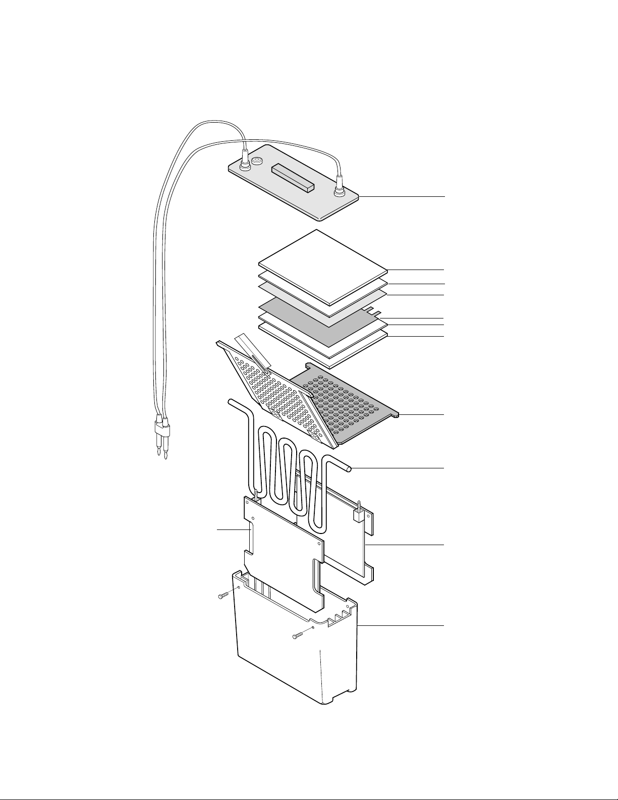
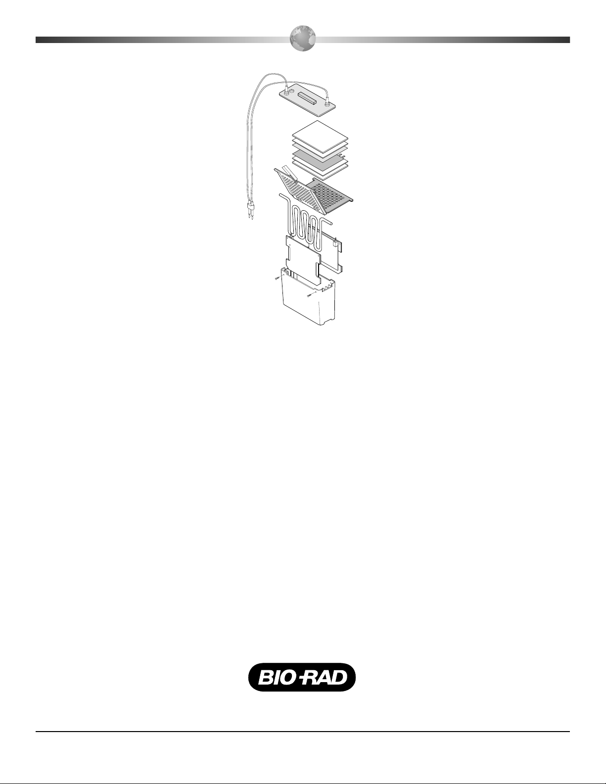
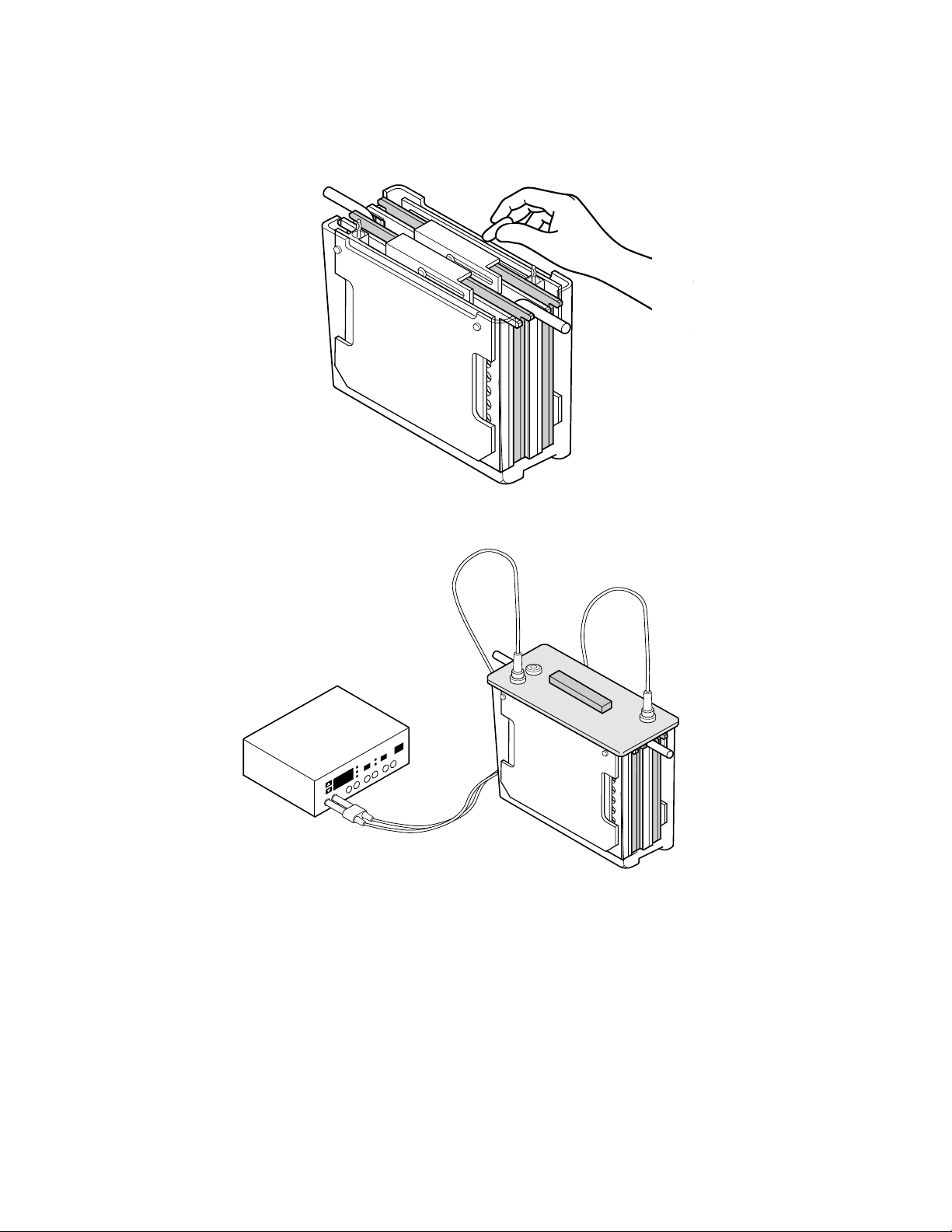
Trans-Blot Cell Description & Assembly of Parts
3
Lid
Fiber pad
Filter paper
Membrane
Gel
Filter paper
Fiber pad
Gel holder
cassette
Super
cooling coil
Plate cathode
Buffer tank
* Wire electrode
cards not shown
Plate anode
Page 7

Section 2
Trans-Blot Cell Assembly
2.1 Preparation for Blotting
1. Prepare the transfer buffer. (See Section 3.3 for buffer formulation. Using buffer chilled to
4 °C will improve heat dissipation.)
2. Cut the membrane and the filter paper to the dimensions of the gel. Always wear gloves
when handling membranes to prevent contamination. Equilibrate the gel and soak the
membrane, filter paper, and fiber pads in transfer buffer (15 min—1 hour depending on
gel thickness).
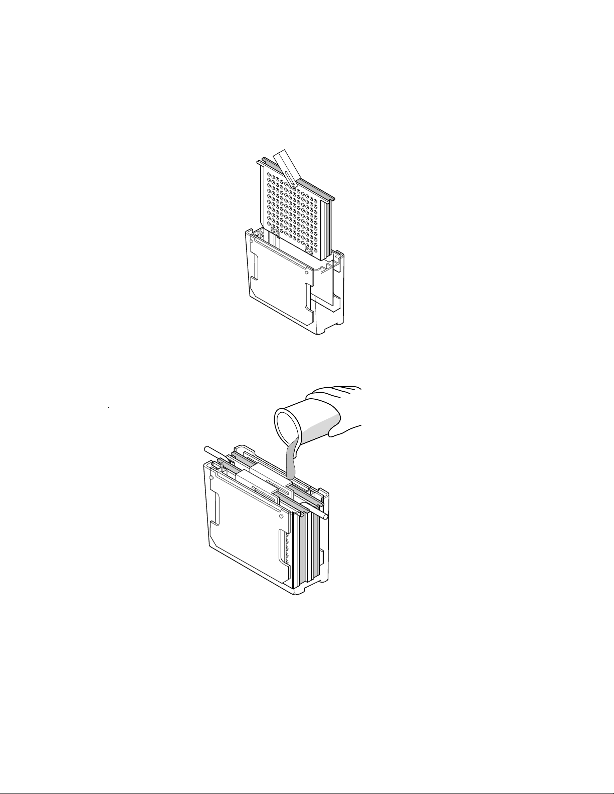
3. Prepare the gel sandwich.
Place the cassette, with the gray side down, on a clean surface.
Place one pre-wetted fiber pad on the gray side of the cassette.
Place a sheet of filter paper on the fiber pad.
Place the equilibrated gel on the filter paper.*
Place the pre-wetted membrane on the gel.*
Complete the sandwich by adding a piece of filter paper on the membrane.*
* Removing any air bubbles which may have formed is very important for good
results. Use a glass tube to gently roll air bubbles out.
Add the last fiber pad.
4
Fiber pad
Filter paper
Membrane
Gel
Filter paper
Fiber pad
Cathode (-) side
Anode (+) side
Page 8
5
4. Close the cassette firmly, being careful not to move the gel and filter paper sandwich.
Lock the cassette closed with the white latch.
5. Place the cassette in tank. Repeat for any other cassettes you may want to run. Completely
fill the tank with buffer.
6. If running high intensity or high voltage with plate electrodes, add the super cooling coil
in any available slot.
Note: For high intensity runs (4 cm inter-electrode distance) only one cassette can be
placed in the tank. The Super Cooling Coil must be used. It is placed outside the electrodes.
See Section 2.2, high intensity field option. Two cassettes can be run with the Super
Cooling Coil in the standard field with the electrodes 8 cm apart, and three cassettes can
be run at low voltage without the super cooling coil.
Page 9
7. Addition of a standard stir bar will help to maintain even buffer temperature and ion dis-
tribution in the tank. Set the speed as fast as possible to keep ion distribution even.
8. Put on the lid, plug the cables into the power supply, and run the blot. Refer to Section 3
for run times and voltage setting with various buffers.
9. Upon completion of the run, disassemble the blotting sandwich and remove the mem-
brane for development. Clean the cell, fiber pads, and cassettes with laboratory detergent
and rinse well with deionized water.
6
Page 10

2.2 High Intensity Field Option
The electrode cards of the Trans-Blot cell can be moved closer together to allow higher
field strengths (V/cm), and thus more efficient, more rapid transfer. To decrease the interelectrode distance, the anode electrode card is moved to the center gel holder position.
1. Remove the screws at the top corners of the anode (red) electrode card.
2. Set up the gel holder with the gel, pads, and membrane following the standard Trans-
Blot cell operation instructions outlined in Section 2.1. Insert the sandwich into the gel
holder slot closest to the cathode (black) electrode panel.
3. Pull the anode card out of the cell, and move it into the middle gel holder slot. The gel
holder will keep the electrode card firmly positioned in the slot.
4. Completely fill the buffer tank to the bottom of the red electrode disc.
5. Place the Super Cooling Coil into the free gel holder slot and place a stir bar in the bot-
tom of the tank. The Super Cooling Coil must be used for adequate heat dissipation of gen-
erated in high-intensity transfer. Set stirring speed as high as possible.
6. Remove the white plug from the electrode cable hole in the Trans-Blot cell lid. Unscrew
the two red screws anchoring the red power cable to the lid. Loosen the screws 4 turns.
Move the cable to its alternative position, aligning shallow holes in the cable with the
anchor screws, and retighten all screws.
7. Begin electrophoretic blotting.
The anode electrode is removed from the standard position and placed 4 cm apart from the
cathode. The cable is also moved to line up with electrodes.
7
Page 11

2.3 Acidic Transfers
If transferring under acidic conditions, switch the gel and membrane in the set up instructions. This will place the membrane on the cathode side of the gel. Under acidic conditions,
proteins will transfer in the opposite direction going toward the negative cathode. Do not
reverse the electrodes themselves. This will cause damage to the instrument.
Section 3
Transfer Conditions
3.1 General Guidelines to Transfer Buffers
and Running Conditions
Tables 3.1 to 3.4 provide guidelines for power conditions using different buffers. Power
conditions are provided for various run times. Where multiple conditions are displayed, the
higher the voltage, the less time required for the run. Note all “requires cooling” warnings.
Table 3.1. SDS-PAGE Gels
Standard Field Standard Field High Intensity Field
Overnight 8 cm electrode distance 4 cm electrode distance
❄
CCCCOOOOOOOOLLLLIIIINNNNGGGGRRRREEEEQQQQUUUUIIIIRRRREEEEDD
DD
Buffer A or B Buffer C Buffer A or B Buffer C Buffer A or B Buffer C
Trans-Blot cell with
30 V, 0.1 A 10 V, 0.1 A 60 V, 0.21 A 20 V, 0.25 A 100–200 V 30–60 V
wire electrodes
0.3–0.8 A 0.4–1.0 A
Overnight 5 hours approximately 30 minutes–4 hours
❄
Buffer A or B Buffer C Buffer A or B Buffer C Buffer A or B Buffer C
Trans-Blot cell with
10 V 5 V 100–150 V 30–50 V 50–100 V 20–40 V
plate electrodes
0.1 A 0.1 A
1–1.5 A 1–1.6 A
0.7–1.6 A 0.7–1.6 A
Overnight 1–5 hours
❄
30 minutes–1 hour
❄
Buffer A: 25 mM Tris, pH 8.3, 192 mM glycine, with or without 20% MEOH and .025%–0.1% SDS.
B: 48 mM Tris, pH 9.2, 39 mM glycine, with or without 20% MEOH and .025%–0.1% SDS.
C: 10 mM NaHCO3, 3 mM NaCO3, pH 9.9, with or without 20% MEOH and .025%–0.1% SDS.
8
Page 12

Table 3.2. DNA and RNA
Standard Field Standard Field High Intensity Field
Overnight 8 cm electrode distance 4 cm electrode distance
❄
COOLING REQUIRED
TAE or TBE TAE TBE TAE TBE
Trans-Blot cell with
30 V, 0.2 A 60 V, 0.6 A 80 V, 0.55 A 80–100 V 100–130 V
wire electrodes
0.8–1.4 A 0.7–1.1 A
Overnight 5 hours approximately 30 minutes–4 hours
❄
Trans-Blot cell with
TAE or TBE TAE TBE TAE TBE
plate electrodes
15 V, 0.2 A 20–35 V, 75–100 V 15–25 V 50–90 V
0.8–1.5 A 0.8–1.1 A 0.8–1.4 A 0.7–1.1 A
Overnight 1–5 hours
❄
30 minutes–1 hour
❄
1x TAE: 40 mM Tris-Acetate, 1.0 mM EDTA
1x TBE: 90 mM Tris-Borate, 2.0 mM EDTA
Table 3.3. Native Gels
Standard Field Standard Field High Intensity Field
Overnight 8 cm electrode distance 4 cm electrode distance
❄
COOLING REQUIRED
Trans-Blot cell with
30 V, 0.1 A 60 V, 0.21 A 100–200 V
wire electrodes
0.3–0.8 A
Overnight 5 hours approximately 30 minutes–4 hours
❄
Trans-Blot cell with
10 V 100–150 V 50–100 V
plate electrodes
0.1 A 1–1.5 A 0.7–1.5 A
Overnight 1–5 hours
❄
30 minutes–1 hour
❄
Buffer: 25 mM Tris, pH 8.3,192 mM glycine. No methanol.
Table 3.4. Isoelectric Focusing, Native Gels, Basic Proteins, Acid Urea Gels
Standard Field Standard Field High Intensity Field
Overnight 8 cm electrode distance 4 cm electrode distance
❄
COOLING REQUIRED
Trans-Blot cell with
30 V, 0.2 A 70 V, 0.5 A 100–150 V, 0.55–0.85 A
wire electrodes
Overnight 5 hours approximately 30 minutes–4 hours
❄
Trans-Blot cell with
15 V, 0.2 A 40–70 V, 0.6–1.0 A 30–-60 V, 0.6–1.0 A
plate electrodes
Overnight 1–5 hours
❄
30 minutes–1 hour
❄
Buffer: 0.7% Acetic Acid
3.2 Notes on Electrophoretic Transfer Conditions
These variables will change total resistance and thus the current readings:
• Alterations in buffer make-up, i.e., addition of SDS, or changes in ion concentration
due to addition of acid or base to adjust the pH of the buffers.
• Gel pH, ionic strength, and percentage of acrylamide, especially if the gel has not
been properly equilibrated.
• Number of gels; current increases slightly as the number of gels increases.
• Volume of buffer; current increases when volume increases.
• Platinum mass; current increases when mass increases.
• Transfer temperature; current increases when temperature increases.
• Time in transfer at which reading was taken; current normally increases as the buffering capacity diminishes with progress of the run.
9
Page 13

2. Pre-equilibration of gels
All electrophoresis gels should be pre-equilibrated in transfer buffer prior to electrophoretic
transfer. Pre-equilibration will facilitate the removal of contaminating electrophoresis
buffer salts and neutralization salts (salts resulting from the denaturation of nucleic acids
prior to transfer). If the salts are not removed, they will increase the conductivity of the
transfer buffer and the amount of heat generated during the transfer. Also, low percentage gels (<12%) will shrink in methanol buffers. Equilibration allows the gel to adjust to
its final size prior to electrophoretic transfer.
3. Current limits
The PowerPac 200 Power Supply is capable of a 200 watt output. Unless a current limit
is set, uncontrolled conductivity changes may result in full power being delivered to the
Trans-Blot cell. The gel holder and electrode cards may warp, and the transfer buffer may
boil and evaporate (further increasing conductivity). This would result in a potential safety hazard. Refer to the PowerPac 200 Power Supply Instruction Manual for setting current limits and run times.
4. Polarity of transfer
Do not reverse polarity with the plate electrodes. This will result in corrosion and rusting
of the stainless steel cathode. If this should occur, the stainless steel should be cleaned with
a mild abrasive cleanser to remove the rust.
5. Heat dissipation with the Super Cooling Coil - Use of the Super Cooling Coil with the
Plate Electrodes
For high power applications, such as high intensity transfers and transfers performed with
the plate electrodes, efficient heat removal is only obtained using the Super Cooling Coil
connected to a refrigerated recirculating bath. Placing the Trans-Blot cell in the cold room
is an inadequate means of controlling transfer buffer temperature. The plastic tank of the
Trans-Blot cell is an effective thermal insulator, thus limiting the efficient dissipation of
heat. Use of the Super Cooling Coil is necessary with all experiments using the plate electrodes and with high intensity transfers using the standard platinum wire electrodes.
6. Use of a stir bar during transfer
For all blotting applications a stir bar must be placed inside the Trans-Blot cell, so that the
transfer buffer is stirred during the course of the experiment. This will help to maintain
uniform conductivity and temperature during electrophoretic transfer. Failure to properly control transfer buffer temperature results in poor transfer of macromolecules and poses
a potential safety hazard.
7. Transfer buffer pH
Do not adjust the pH of transfer buffers unless specifically indicated. Adjustments of the
pH of transfer buffers, when not indicated, will result in increased buffer conductivity. This
is manifested by a higher than expected initial current output and a decreased resistance.
It is recommended that the buffer conductivity and resistance be checked with the
PowerPac 200 Power Supply before starting each transfer.
10
Page 14

8. Transfer buffer recommendations
Use only high quality, reagent grade methanol. Contaminated methanol can result in
increased transfer buffer conductivity, as well as poor transfer of macromolecules. Do
not reuse transfer buffers or dilute transfer buffers below recommended levels. Reuse of
transfer buffers is not advised, since these buffers have most likely lost their ability to
maintain a stable solution pH during transfer. Dilution of transfer buffers below their recommended levels is also not advised, since this will decrease their buffering capacity.
9. Voltage limits
Do not increase voltage settings beyond those indicated in Tables 3.1–3.4 for overnight
operation. Buffer conductivity must be close to the current listed and a current limit should
be set on the power supply. If overnight transfers at low voltages are ineffective for your
application, and higher voltages are necessary, transfer times must also be decreased.
Failure to do so may result in a potential safety hazard.
3.3 Buffer Formulation
All formulas provided below are for a total volume of 1 liter of buffer. Four liters of
buffer are required for the Trans-Blot cell.
DO NOT ADD ACID OR BASE TO ADJUST pH OF THE FOLLOWING
BUFERS. Methanol should be analytical reagent grade, as metallic contaminants in low
grade methanol will plate on the electrodes.
Note: Some pH electrodes will not perform a proper measurement for the pH of Tris
buffers. If the pH of the buffer is off, check to make sure the electrode is designed to
work with Tris buffers. If the pH electrode functions properly for Tris buffers and the
pH is below 8.0, remake the buffer.
1. 25 mM Tris, 192 mM glycine, 20% v/v methanol, pH 8.3
Mix 3.03 g Tris, 14.4 g glycine, and 200 ml of methanol; add distilled deionized water
(dd H2O) to 1 liter.
2. 25 mM Tris, 192 mM glycine, pH 8.3
Mix3.03gTrisand14.4gglycine;addddH2O to 1 liter.
3. 48 mM Tris, 39 mM glycine, 20% v/v methanol, pH 9.2
Mix 5.82 g Tris and 2.93 g glycine in ddH2O, add 200 ml methanol
Bring to 1 liter with ddH2O
4. 48 mM Tris, 39 mM glycine, pH 9.2
Mix 5.82 g Tris and 2.93 g glycine
Add ddH2O to 1 liter
5. 10 mM NaHCO3,3mMNaCO3, 20% methanol, pH 9.9
Mix 0.84 g NaHCO3and 318 g Na2CO3in ddH2O, add 200 ml methanol
Bring to 1 liter with ddH2O
11
Page 15

12
6. 1.0x TBE (Tris-Borate EDTA) pH 8.3
90 mM Tris-Borate 1 mM EDTA
5x stock solution
54 g Tris base
27.5 boric acid
20 ml 0.5 m EDTA (pH 8.0)
Add 200 ml 5x stock to 800 ml ddH2O to make 1.0x working solution.
7. 1x TAE (Tris-Acetate EDTA)
40 mM Tris-Acetate 1 mM EDTA
50-x stock solution
242 g Tris base
57.1 ml glacial acetic acid
100 ml 0.5 m EDTA (pH 8.0)
1x working solution, add 20 ml 50x stock to 980 ml ddH2O
Section 4
Strategies for Optimizing Electro-Elution
4.1 Optimizing Protein Transfer
Generally, quantitative elution of denatured high molecular weight proteins is difficult.
The following tactics, alone or in combination, will increase transfer efficiency.
1. Vary gel composition
a. Gradient gels are often more effective than single gel concentrations for elution of a
wide range of molecular weight proteins.
b. Lower the total monomer to create a more porous gel.
c. Increase or decrease the percentage of crosslinker. A 5.26% C gel will contain the
smallest pore size of all gels no matter what the concentration of acrylamide. An
increase or decrease in %C will make gels more porous with little loss in resolution.
grams bis
grams bis + grams acrylamide
2. Increase transfer time. An initial control should be performed to determine the time
required for complete transfer.
17, 24
Times may vary from as little as 30 minutes to as long
as overnight. Remember all overnight applications should be performed at 30–50 volts to
minimize heating problems. (For long transfers at elevated voltages use the standard
Trans-Blot cell with the super cooling coil.)
3. Increase the power. Initial controls should be performed to evaluate the efficiency of
increasing the V/cm as well as its effects on the temperature of transfer. The temperature
increase may change buffer resistance and subsequent power delivered, as well as the
state of protein denaturation, thus affecting transfer efficiency.
4. Reduce buffer strength. Dilution of transfer buffer results in lower current at any given
voltage. This will allow the use of higher voltages without excessive heating.
x 100
%C=
Page 16

5. Vary buffer type and pH
a. Maximize charge-to-mass ratio. It appears that alcohols present in SDS transfer buffer
strip SDS from proteins. Basic proteins in Tris, glycine, methanol buffer at pH 8.3 may
assume a state near isoelectric neutrality and thus transfer poorly. For example, lysozyme
exhibits this behavior. Buffers with pH of 9.5 to 10.0 have shown much better elution
and binding characteristics for basic proteins such as lysozyme and histones.
41
b. Different buffer types at similar V/cm may yield different efficiencies. Generally
Tris buffers allow more efficient transfer than acetate or phosphate buffers.
6. Addition of 0.1% SDS detergent to Tris, glycine, methanol buffer has been reported to
increase transfer efficiency.24SDS, however, increases relative current, power, and heating. Also, temperatures below 10 °C may precipitate the SDS so the starting buffer temperature will be higher. SDS may also affect the antigenicity of some proteins. SDS will
aid in eluting the proteins from the gel, but it may reduce the binding efficiency of those
proteins to the nitrocellulose membrane.
42
7. Eliminate alcohol from the transfer buffer. Alcohol in the transfer buffer improves binding of SDS proteins to nitrocellulose only. Elimination of alcohol results in increased
transfer efficiency but diminishes binding to nitrocellulose. Transfer efficiency is increased
because alcohol causes gel pores to contract resulting in fixation of large molecular weight
proteins within the gel matrix. Use of PVDF membrane for SDS protein transfers eliminates the alcohol requirement, and constitutes a logical strategy for analysis of high molecular weight or difficult-to-transfer proteins.
26, 27
8. Limited protease treatment. A protocol for protease digestion of protein during transfer has
been published.22Efficient transfer without loss of immunological reactivity was reported.
9. Alter membrane type. As mentioned in 7, PVDF membrane allows transfer in the absence
of alcohol.
10. Alter gel system. If possible, use non-denaturing gradient pore gels for separation of proteins by molecular weight. Isoelectric focusing gels, or native gels, may be considered if
separation by molecular weight is not mandatory.
11. Failure of molecules to bind efficiently to the membrane, caused by poor gel-membrane
contact, is often confused with inefficient elution. Poor contact is usually due to excess
moisture in the gel-membrane interface. Proper technique and the use of a test tube or
glass pipet as a “rolling pin” should assure good contact. Proper selection of filter paper
spacers will help assure good compression. Gel and membrane equilibration in transfer
buffer for 30 minutes to 1 hour prior to transfer will help prevent shrinking of either component during transfer, and will eliminate reactants such as urea or SDS from the gel.
4.2 Optimizing DNA and RNA Transfer
Problems with elution of nucleic acids can be solved by altering the gel percentage. It
may be somewhat more difficult to quantitatively transfer large amounts of DNA used in
genomic blots. The following tactics should be considered for optimizing elution in such
transfers.
1. Alter gel composition.
a. Lower % total monomer or % crosslinker for polyacrylamide gels.
b. Lower % agarose. This allows better elution of high molecular weight DNA.
2. Alter DNA denaturants. It has been found that glyoxal denaturation allows more efficient
elution of DNA than NaOH. Boiling polyacrylamide gels to denature DNA has also been
found to give excellent results.11Base denaturation often causes polyacrylamide gels to
weaken and stick to blotting membranes.
13
Page 17

Section 5
Choice of Blotting Membranes
5.1 Protein Blotting Membranes
Nitrocellulose Membrane
Nitrocellulose membranes have been used extensively for protein binding and
detection.
7,20,23,24,27
They can be easily stained for total protein by a dye stain (Amido Black,
Coomassie®Blue, Ponceau S, Fast Green FCF, etc.),27or the more sensitive Colloidal Gold
Total Protein Stain, and also allow either RIA, FIA or EIA.7Nitrocellulose has a high binding capacity of 80-100 µg/cm2. Nonspecific protein binding sites are easily and rapidly
blocked, avoiding subsequent background problems. No pre-activation is required. Low
molecular weight proteins (especially <20,000 daltons) may be lost during post transfer washes, thus limiting detection sensitivity.19Smaller pore size nitrocellulose membrane (0.2 µm),
has been shown to be effective in eliminating this loss.37Large proteins ( 100,000 daltons)
denatured by SDS may transfer poorly due to the addition of alcohol to the transfer buffer.
Alcohol increases binding of SDS-proteins to nitrocellulose, but decreases pore sizes in the
gel. Elimination of alcohol from SDS-protein transfers results in considerably diminished
binding. Adding SDS (up to 0.1%) to the transfer buffer increases the transfer efficiency of
proteins, but reduces the amount of binding to the membrane.17Also, SDS increases the conductivity of the buffer and the heat generated during transfer.
PVDF Membrane
PVDF (Polyvinylidene difluoride) membrane is an ideal support for amino-terminal
sequencing, amino acid analysis and immunoassays of blotted proteins. PVDF retains proteins
under extreme conditions of exposure to acidic or basic conditions, and in the presence of
organic solvents. Greater retention during sequencing manipulations enhances the likelihood
of obtaining information from rare, low abundance proteins, by increased initial coupling and
higher repetitive yields. In addition, PVDF membrane exhibits better binding efficiency of
blotted material in the presence of SDS in the transfer buffer. PVDF must first be wetted in
100% MeOH but can then be used in buffer which does not contain MeOH.
5.2 DNA and RNA Blotting Membrane
Zeta-Probe®Nylon Membrane
Nitrocellulose is not a suitable medium for electrophoretic transfer of nucleic acids, as high
concentrations of salt ( 10 x SSC) are required for efficient binding.13Molecules 500 bp are
not bound at all, even at high salt. Low resistance results when an electric current is passed
through a solution of high salt. This causes potentially damaging high currents (and power)
at very low voltages. Since V/cm is the eluting force, inefficient transfer occurs under conditions required for proper binding. Zeta-Probe membrane allows efficient binding of all sizes
of single stranded DNA and RNA in the presence of low ionic strength buffers.13Zeta-Probe
membrane is an ideal alternative to nitrocellulose for the analysis of nucleic acids. Binding is
more stable through post transfer washes, and reprobing may be performed as many as 10
times.
14
Page 18

Table 5.1 Guide to Protein Blotting Membranes
A variety of blotting membranes is available for immunoblotting, each with particular advantages depending on the needs of the experiment. The physical properties and performance characteristics of a membrane should be evaluated in selecting the appropriate transfer conditions.
Binding
Capacity
Membrane Pore Size (µg/cm2) Notes
Nitrocellulose 0.45 µm 80–100 General purpose protein blotting membrane
0.2 µm
Supported 0.45 µm 80–100 Pure nitrocellulose cast on an inert synthetic support;
Nitrocellulose 0.2 µm increased strength for easier handling and for reprobing.
PVDF 0.2 µm 170–200 High mechanical strength and chemical stability, used for
protein sequencing, and western blotting; enhanced binding
in the presence of SDS. Must be wet in alcohol before equilibration in buffer.
Nylon 0.2 µm 170 Recommended for nucleic acids.
Note: Nucleic acids cannot be transferred to nitrocellulose by electrophoretic blotting.
Use Zeta-Probe membrane.
Section 6
Troubleshooting Guide
Electrophoretic Transfer
Poor electrophoretic transfer (as detected by staining the gel)—Proteins
1. Transfer time is too short.
• Increase the transfer time.
2. Power is too low.
• Always check the current at the beginning of the run. The current may
be too low for a particular voltage setting. If the buffer is prepared
improperly, the conductivity may be too low, and not enough power
will be delivered to the cell. See the power guidelines for specific applications in Section 3.
• Remake the buffer or increase the voltage.
• Try the high intensity blotting option.
3. Transfer apparatus is assembled incorrectly, and the proteins are moving in
the wrong direction.
• The gel/membrane sandwich may be assembled in the wrong order or
the cassette is inserted in the tank facing the opposite orientation. Check
the polarity of the connections to the power supply.
4. Charge-to-mass ratio is incorrect.
• Try a more basic or acidic transfer buffer to increase protein mobility.
Proteins near their isoelectric point at the pH of the buffer will transfer
poorly. (It has been suggested that buffer pH should be
2 pH units higher or lower than the pI of the protein of interest
for optimal transfer efficiency.)
5. Protein is precipitating in the gel.
• Try using SDS in the transfer buffer. SDS can increase transfer efficiency,
but can also reduce binding efficiency to nitrocellulose and affect reactivity of some proteins with antibodies.
15
Page 19

6. Power supply circuit is inoperative, or an inappropriate power supply was
used.
• Check the fuse. Be sure the voltage and current output of the power
supply match the needs of the blotting instrument.
7. Methanol in the transfer buffer is restricting elution.
• Reduction of methanol results in increased transfer efficiency of
proteins from the gel, but it also diminishes binding to nitrocellulose
and PVDF.
8. Gel percentage too high.
• Reduce %T (total monomer) or %C (crosslinker). A 5% C (with bis as
the crosslinker) will produce the smallest pore size gel. Decreasing from
this concentration will increase the pore size and increase transfer efficiency.
Poor transfer—nucleic acid
1. Gel percentage is too high.
• Reduce the %T or %C in the acrylamide gel or reduce % agarose in an
agarose gel.
• Prior to transfer, cleave DNA in dilute 0.25 M HCl or RNA in dilute
NaOH.
2. Transfer time is too short or power conditions are too low.
• Increase the transfer time, or try high intensity transfer.
3. DNA or RNA cannot be transferred electrophoretically to nitrocellulose,
since high salt concentrations are required for efficient binding.
• Use Zeta-Probe membrane instead of nitrocellulose.
Swirls or missing bands; diffuse transfers
1. Poor contact between the membrane and the gel. Air bubbles or excess
buffer remain between the blot and gel.
• Use a test tube or pipet as a rolling pin, and roll over the membrane
carefully in both directions until air bubbles or excess buffer is removed
from between gel and membrane, and complete contact is established.
• Use thicker filter paper in the gel/membrane sandwich.
• Replace the fiber pads. Pads will compress with time, and will not hold
the membrane to the gel.
2. Power conditions are too high.
• Always check the current at the beginning of the run. The current may
be too high for a particular voltage setting. If the buffer is
prepared improperly, the conductivity may be too high, resulting in
excessive power delivered to the cell. See the power guidelines for
specific applications in Section 3.
3. The membrane is not properly wet or has dried out.
• White spots on the nitrocellulose membrane indicate dry areas where
protein will not bind. If wetting does not occur immediately by immersion of the sheet in transfer buffer, heat distilled water until just under
the boiling point, and soak the membrane until completely wet.
Equilibrate in transfer buffer until ready for use.
• Because of the hydrophobic nature of PVDF, the membrane must be
prewet in methanol prior to equilibration in aqueous transfer buffer.
Follow the directions in the product insert.
16
Page 20

4. The gel electrophoresis may be at fault.
• Artifacts of electrophoresis may be produced by poor polymerization,
inappropriate running conditions, contaminated buffers, sample overload, etc. Consult your electrophoresis manual for more details.
Gel cassette pattern transferred to blot
1. Contaminated or thin fiber pads are used.
• Replace the fiber pads, or thoroughly clean the contaminated pads.
2. Excessive amounts of protein were loaded on the gel, or too much SDS was
used in the transfer buffer. Proteins can pass through the membrane without binding, and recirculate through the tank blotting system.
• Reduce the amount of protein on the gel, and SDS in the transfer buffer.
Add a second sheet of membrane to bind excess protein.
3. The transfer buffer is contaminated.
• Make fresh solutions.
Poor binding to the membrane — Nitrocellulose
1. Nitrocellulose requires 20% methanol in the transfer buffer for optimal
protein binding.
• Make sure the buffer contains the proper amount of methanol.
2. Proteins may be transferring through the nitrocellulose.
• Use PVDF or nylon (higher binding capacities) or 0.2 µm nitrocellulose
(smaller pore size). Decrease the voltage or move the electrodes to the
standard position if using the high intensity option.
3. Mixed ester celluloses bind proteins poorly.
• Use pure nitrocellulose.
4. Proteins <15,000 daltons may show diminished binding to 0.45 µm nitrocellulose, or may be washed from the membrane during assays.
• To increase stability of binding, proteins can be crosslinked to
nitrocellulose with glutaraldehyde.
• Use PVDF or nylon membrane, which have higher binding capacities.
• Use Tween-20 detergent in the wash and antibody incubation steps.
Reduce or eliminate the more stringent washing conditions.
5. SDS in the transfer buffer will reduce binding efficiency of proteins.
• Reduce or eliminate the SDS from the transfer buffer.
6. The membrane may not be completely wet.
• White spots on the membrane indicate dry areas where protein will not
bind. If wetting does not occur immediately by immersion of the sheet
in transfer buffer, heat distilled water until just under the boiling point,
and soak the membrane until completely wet. Equilibrate in transfer
buffer until ready for use.
Poor Binding to the Membrane — PVDF
1. The membrane may not be completely wet.
• Because of the hydrophobic nature of PVDF, the membrane must be
prewet in alcohol prior to equilibration in aqueous transfer buffer.
Follow the directions in the product insert.
2. The membrane may have been allowed to dry during handling.
• A completely wet membrane has a gray, translucent appearance. White
spots will form on the surface of the membrane, indicating that it has
been allowed to dry. Since proteins will not bind to the dry spots, rewet
the membrane with methanol and re-equilibrate in transfer buffer.
17
Page 21

Immune-Specific Detection
Overall High Background
1. Blocking conditions are inappropriate.
• Match the blocker to the membrane. For example, nylon and PVDF
membranes require more extensive blocking, usually with non-fat dry
milk.
• Increase the concentration or blocking time as necessary.
• The blocker must be a pure protein. The blocker may be contaminated
with material that bind probes non-specifically.
2. Insufficient wash protocols are used.
• Increase the number, duration, or stringency of the washes. Include progressively stronger detergents in the washes, e.g.
SDS
is
stronger than
NP-40 which is stronger than
Tween-20
. Also, include Tween-
20
in the antibody dilution buffers to reduce nonspecific binding.
3. The blot is left in the substrate too long.
• Remove the blot from the substrate solution when the signal-to-noise
level is acceptable. Do not overdevelop. Stop the reaction immediately
by immersing the blot in dd H2O.
4. Contamination occurred during a previous step, e.g. electrophoresis
or transfer.
• Discard and remake the gel and transfer solutions.
• Replace or thoroughly clean contaminated fiber pads, if a tank blotter
was used. Excessive amounts of protein were loaded on the gel, or too
much SDS was used in the transfer buffer. Proteins can pass through the
membrane without binding and recirculate through a tank blotting system. Reduce the amount of protein on the gel or SDS in the transfer
buffer. Add a second sheet of membrane to bind excess protein.
5. Primary or secondary antibody is too concentrated.
• Increase the dilution of the antibodies. Perform a dot-blot experiment to
optimize the working concentrations.
6. Incubation trays are contaminated.
• Clean the trays or use disposable trays.
Nonspecific Reactions between Bound Proteins and Probes
1. Primary or secondary antibody is contaminated with nonspecific or
species cross-reactive IgG.
• Use purified IgG first antibody fractions and affinity-purified blotting
grade secondary antibody.
2. Monoclonal antibodies may react non-specifically with SDS denatured proteins.
• Compare the binding of other monoclonal or polyclonal antibodies.
• Blot native proteins as a comparison.
3. Nonsense interactions are occurring due to ionic associations. For example,
avidin, a glycosylated protein, may bind to more acidic proteins on blots.
• Increase the ionic strength of the incubation buffers. Increase the number, duration or stringency of the washes. Include progressively stronger
detergents in the washes, e.g. SDS is stronger than NP-40 which is
stronger than Tween-20. Include Tween-20 in the antibody dilution
buffers to reduce nonspecific binding.
18
Page 22

No Reaction or Weak Signal
1. The sample load was insufficient.
• Increase the amount of protein applied. Concentration of the sample
prior to loading may be necessary. Use a more sensitive assay system
(see Table 2.10).
2. Insufficient antigen binding to the membrane is occurring.
• Stain the gel after transfer or use prestained or Kaleidoscope standards
to assess transfer efficiency. See the previous section for suggestions on
improving transfer related problems.
3. Antigen denaturation is occurring during electrophoresis or transfer.
Antibodies, especially monoclonals, may not recognize denatured antigens.
• Electrophorese and transfer proteins under native conditions. Use the
Super Cooling Coil and a refrigerated recirculating bath to transfer heatsensitive proteins.
4. Primary or secondary antibodies may be inactive or non-saturating.
• Store the reagents at recommended conditions. Avoid repeated freezethaw cycles, bacterial contamination, or heat inactivation.
• Detergents may affect the activity of some antibodies. Eliminate them
from the assay, except for the wash after blocking.
• If the antibody titer is too low, optimize the concentration using a
dot-blot experiment.
• Increase the antibody incubation times.
5. The enzyme conjugate is inactive or non-saturating.
• Test the reagent for activity (see below).
• Store the reagents at recommended conditions. Avoid repeated freezethaw cycles, bacterial contamination, or heat inactivation.
• Sodium azide is a potent inhibitor of horseradish peroxidase. Use
Thimerosal as a bacteriostat.
• Impure water may cause inactivation of the enzyme. Use only distilled,
deionized water.
• If the conjugate concentration is too low, optimize using a dot-blot
experiment.
6. Color development reagent is inactive.
• Test the reagent for activity (see below) and remake if necessary.
Tests for Monitoring Reagent Activity
1. Activity test for the color development solution.
• Combine 1.0 ml of the color development solution with 10 µl of full
strength second antibody conjugate. The color reaction should develop immediately. If color fails to develop within a few minutes, the color
development solution is inactive. Make up a fresh working solution and
repeat the color development assay.
2. Activity test for the conjugate solution.
• Combine 1.0 ml of the color development solution tested above and 1.0
ml of the 1:3,000 dilution conjugate solution. A light blue tinge should
develop within 15 minutes. If color fails to develop within 25 minutes, the conjugate solution is suspect. Repeat the procedure with a
freshly prepared dilution of conjugate.
19
Page 23

3. Activity test for the first antibody solution.
• Use an ELISA, RID, Ouchterlony immunodiffusion, or precipitation test
to determine reactivity of the antibody with the antigen. If possible,
repeat the assay procedure with several dilutions of first antibody solution.
Total Protein Detection
Colloidal Gold Total Protein Stain — High Background
1. The blocking step is insufficient or omitted.
• Block with 0.3% Tween-20 in TBS, using three washes of 20 minutes
each.
2. The membrane used is not compatible with this stain.
• Positively charged nylons cannot be used with Colloidal Gold stain. Use
the Biotin-Blot Total Protein Detection Kit instead.
3. Contamination of the membrane occurred at a previous step, i.e. electrophoresis or transfer.
• Discard and remake the gel and transfer solutions.
• Replace or thoroughly clean contaminated fiber pads.
4. Excessive amounts of protein are loaded on the gel, or too much SDS is
used in the transfer buffer. Proteins can pass through the membrane without binding and recirculate through a tank blotting system
• Reduce the amount of protein on the gel or SDS in the transfer buffer.
Add a second sheet of membrane to bind excess protein.
5. Colloidal gold stain solution is contaminated.
• The stain is a reusable reagent. Be sure to use a separate, clean plastic
container to store previously used reagent in the refrigerator. Discard
any reagent that has viscous sediment at the bottom of the bottle. If the
solution does not have a dark burgundy color, but is a light blue, the
stain was contaminated with buffer salts. Buffer salts will react with the
gold sol causing non-specific precipitation of the reagent onto the membrane. Discard this solution.
Colloidal Gold Total Protein Stain — Low Sensitivity
1. Increase the incubation time for detection of low level signals.
• Overnight incubations are possible, although background staining can
increase.
2. Transfer is incomplete.
• See poor transfer for suggestions on how to enhance transfer efficiency.
3. Stain is exhausted, as evidenced by the loss of the dark burgundy color and
longer staining times.
• Discard the reagent.
4. Buffer salt contamination has occurred. The solution will be light blue
instead of dark burgundy.
• Discard the reagent.
5. The sample load may be too low for the reagent to detect.
• Use the Gold Enhancement Kit for detection levels as low as 10 pg of
protein per band.
20
Page 24

Biotin-Blot Total Protein Detection — High Background
1. Blocking conditions are insufficient.
• Match the blocker to the membrane. Nylon membranes require the
addition of 1-methyl-2-pyrrolidinone (MPO) to several solutions.
Consult the Biotin-Blot manual for specific details.
2. Membrane is left in color development solution too long.
• Remove the membrane from the color development solution when the signal is apparent and the background has not developed. Transfer the blot to
distilled water immediately to stop the development.
3. Excessive amounts of protein are loaded on the gel, or too much SDS is
used in the transfer buffer. Proteins can pass through the membrane without binding and recirculate through a tank blotting system
• Reduce the amount of protein on the gel or SDS in the transfer buffer.
Add a second sheet of membrane to bind excess protein.
Biotin-Blot Total Protein Detection — No Reaction
or Weak Color Development
1. Transfer is incomplete.
• See Poor Transfer for suggestions on how to enhance transfer efficiency.
2. The sample load may be too low for the reagents to detect.
• Increase the amount of protein loaded on the gel.
3. NHS-biotin solution is inactivated.
• NHS-biotin hydrolyzes in aqueous solutions. Equilibrate the reagent vial
to room temperature before opening to prevent condensation of water
inside the container. Use a sterile syringe to remove reagent to prevent
contamination.
• Add the NHS-biotin reagent to the Borate-Tween solution just prior to
use.
4. Amine containing buffer salts compete for the biotinylation reagents.
• Wash the membrane thoroughly in Borate-Tween to remove any residual buffer salts from electrophoresis and transfer.
5. Avidin-HRP conjugate is inactive.
• Follow the activity test procedures to determine if the reagent is inactive.
6. Color development solution is inactive.
• Follow the activity test procedures to determine if the reagent is inactive.
Anionic Dyes — High Background
1. Destaining is insufficient.
• Increase the number and duration of washes with the destaining solution.
2. Dye solution is too concentrated.
• Remake the solution.
3. Nylon membranes are not compatible with anionic dyes.
• Use the Biotin-Blot Protein Detection Kit.
Anionic Dyes — Low Sensitivity
1. Anionic dye stains do not detect protein bands below ~100 ng.
• Use a more sensitive stain such as the Colloidal Gold stain or the BiotinBlot Protein Detection Kit.
• Increase the sample load to achieve the detection level of the anionic dye
stains.
21
Page 25

Section 7
Product Information
Catalog
Number Product Description
170-3939 Trans-Blot Cell with Plate Electrodes, complete, includes 2 Gel
Holder cassettes, Super Cooling Coil, cell with lid and power
cables, and fiber pads
170-3946 Trans-Blot Cell with Plate Electrodes, includes Gel Holder cas-
settes, cell with lid and power cables, and fiber pads
170-3910 Trans-Blot Cell with Wire Electrodes, includes Gel Holder, cell
with lid and power cables, and fiber pads
PowerPac 200 Power Supply
165-5052 PowerPac 200 Power Supply, 110/120 V
165-5053 PowerPac 200 Power Supply, 220/240 V
Trans-Blot Cell Accessories
170-3943 Trans-Blot Platinum Anode Plate Electrode
170-3944 Trans-Blot Stainless Steel Cathode Plate Electrode
170-3945 Trans-Blot Plate Electrode Pair, platinum anode and stainless
steel cathode
170-3920 Trans-Blot Standard Wire Electrode Card, cathode
170-3921 Trans-Blot Standard Wire Electrode Card, anode
170-3912 Super Cooling Coil (required for all high intensity transfers)
170-3914 Fiber Pads, 15.5cmx20.5cmx6mm,6
170-3913 Gel Holder
170-3922 Trans-Blot Cell Buffer Tank
170-3923 Trans-Blot Cell Lid with Cables
170-3955 Filter Paper, 14 x 16 cm, 25
170-3956 Filter Paper, 15 x 20 cm, 25
Section 8
References
1. Souhern, E.M, J Mol. Biol., 98, 503 (1975).
2. Alwine, J. C., Kemp, D. J., Parker, B. A., Reiser, J., Renart j., Stark, G. R. and Wahl, G. W., Methods
Enzymol., 68, 220 (1979).
3. Thomas, P. S., Proc. Nat. Acad Sci., 77, 5201 (1980).
4. Seed, B., Nuc. Acids Res., 10, 1799 (1982).
5. Renart. J., Peiser, J. and Stark, G. R., Proc. Nat. Acad. Sci., 76, 3116 (1979).
6. Bowen, P., Steinberg, J., Laemmli, U. K. and Weintraub, H., Nuc. Acids Res., 8, 1 (1980).
7. Towbin, H., Staehelin, T. and Gordon,J., Proc. Nat. Acad. Sci., 76, 4350 (1970).
8. Bittner, M., Kupferer, P. and Morris, C. R., Anal. Biochem., 102, 459 (1980).
22
Page 26

9. Stellwag, E. J. and Dahlberg, A. E., Nuc. Acids Res., 8, 299 (1980).
10. Kutateladze, T. V., Axelrod, B. D., Gorbulev, V. G., Belzhelarshaya, S. N. and Vartikyan, R. M.,
Anal. Biochem., 100, 129 (1979).
11. Peudelhuber, T. L., Ball, D. J., Davis, A. H. and Garrard, W. J., Nuc. Acids Res., 10, 1311 (1982).
12. Danner, D. B., Anal. Biochem., 125, 139 (1982).
13. Bio-Rad Technical Bulletin 1110 “Zeta-Probe Blotting Membranes” (1982).
14. Holland, L. J. and Wangh, L. H., Nuc Acids Res., 10, 3283 (1983).
15. Syminton, J., Green, M. and Brackmann, K., Proc. Nat. Acad. Sci., 78, 177 (1981).
16. Reiser, J. and Wardale, J., Eur. J. Biochem., 114, 569 (1981).
17. Burnette, W. N., Anal. Biochem., 112, 195 (1981).
18. Legocki, R. P. and Verma, D. P. S., Anal. Biochem., 111, 385 (1981).
19. Lin, W. and Kasamatsu, H., Anal. Biochem., 128, 302 (1983).
20. Anderson, N. L., Nance, S. L., Pearson, T. W. and Anderson, N.G., Electrophoresis, 3, 135( 1982).
21. McLellan, T. and Pamshaw, J. A. M., Biochem. Genetics, 19, 647 (1981).
22. Gibson, W., Anal. Biochem., 118, 1 (1981).
23. Howe, J. G. and Hershey, J. W. B., J. Biol. Chem., 2566, 12836 (1981).
24. Erickson, P. G., Minier, L. N. and Lasher, P. S., J. Immun. Meth., 51, 241 (1982).
25. Tsang, V. C. W., Peralta, J. M. and Simons, A. R., Meth. Enzymol., 92, 377 (1983).
26. Gershoni, J. M. and Palade, G. E., Anal. Biochem., 124, 396 (1982).
27. Gershoni, J. M. and Palade, G. E., Anal. Biochem., 131,1(1983).
28. Symington, J., “Two Dimensional Gel Electrophoresis of Proteins: Methods and Applications.”
Celis, J. E. and Bravo, R., eds. Academic Press, N.Y., (1983).
29. Andrews, A. T., “Electrophoresis: Theory, techniques, and biochemical and clinical application,”
2nd ed., Clarendon Press, Oxford, (1986).
30. Beisiegel, V., Electrophoresis, 7, 1 (1986).
31. Bio-Rad Laboratories, unpublished.
32. Gershoni, J. M., in Advances in Electrophoresis, Vol. 1. Chrambach, A., Dunn, M. J. and Radola,
B. J., eds., VCH, Weinheim, in press.
33. Gershoni, J. M. , in Methods of Biochemical Analysis, Vol. 33, Glick, D., ed., Wiley, New York,
in press.
34. Bjerrum, O. J. and Schafer-Nielsen, C., Analytical Electrophoresis, M. J. Dunn, ed. (VCH,
Weinheim), p. 315.
35. Dunn, S. D., Anal. Biochem., 157, 144 (1986).
36. Zeta-Probe Instruction Manual, Bio-Rad Laboratories, (1988).
37. Polvino, W. J., Saravis, C. A., Sampson, C. E. and Cook, R. B., Electrophoresis, 4, 368 (1983).
39. Bio-Rad Laboratories, Biotin-Blot Total Protein Stain Instruction Manual (1985).
40. LaRochelle, W. J. and Froehner, S. C., J. Immunol. Meth., 92, 65 (1986).
41. Szewcyzyk, B. and Kozloff, L. M., Anal. Biochem., 150, 403 (1985).
42. Perides, G., Plagens, U. and Traub, P., Anal. Biochem., 152, 94 (1986).
Scotch-Brite®is a registered trademark of 3M Company.
Gel-Bond
TM
is a trademark of FMC.
Mylar
®
is a registered trademark of E.I. DuPont de Nemours Co.
Coomassie is a trademark of ICI.
23
Page 27

Bio-Rad
Laboratories
Life Science
M1703910 Rev D
Group
2000 Alfred Nobel Drive
Hercules, California 94547
Telephone (510) 741-1000
Fax: (510) 741-5800
Australia,
Austria,
Belgium,
Canada,
China,
Denmark,
Finland,
France,
Germany,
India,
Bio-Rad Laboratories, C-248 Defence Colony, New Delhi 110 024•Phone 91-11-461-0103•Fax 91-11-461-0765
Italy,
Bio-Rad Laboratories S.r.l.,Via Cellini, 18/A, 20090 Segrate Milano•Phone 02-21609 1•Fax 02-21609-399
Japan,
The Netherlands,
New Zealand,
Pacific,
Singapore,
Spain,
Sweden,
Switzerland,
United Kingdom,
Bio-Rad Laboratories Pty Limited, Block Y Unit 1, Regents Park Industrial Estate, 391 Park Road, Regents Park, NSW 2143•Phone 02-9414-2800•Fax 02-9914-2888
Bio-Rad Laboratories Ges.m.b.H., Auhofstrasse 78D, 1130 Wien•Phone (1) 877 89 01•Fax (1) 876 56 29
Bio-Rad Laboratories S.A./N.V., Begoniastraat 5, 9810 Nazareth Eke•Phone 09-385 55 11•Fax 09-385 65 54
Bio-Rad Laboratories (Canada) Ltd., 5671 McAdam Road, Mississauga, Ontario L4Z 1N9•Phone (905) 712-2771•Fax (905) 712-2990
Bio-Rad Laboratories, 14, Zhi Chun Road, Hai Dian District, Beijing 100088•Phone (01) 2046622•Fax (01) 2051876
Bio-Rad Laboratories, Symbion Science Park, Fruebjergvej 3, DK-2100 Copenhagen•Phone39179947•Fax 39 27 1698
Bio-Rad Laboratories, Business Center Länsikeskus, Pihatörmä 1A SF-02240, Espoo,•Phone 90 804 2200•Fax 90 804 1100
Bio-Rad S.A., 94/96 rue Victor Hugo, B.P. 220, 94 203 Ivry Sur Seine Cedex•Phone (1) 49 60 68 34•Fax (1) 46 71 24 67
Bio-Rad Laboratories GmbH, Heidemannstraße 164, D-80939 München/Postfach 450133, D-80901 München•Phone 089 31884-0•Fax 089 31884-100
Nippon Bio-Rad Laboratories, 7-18, Higashi-Nippori 5-Chome, Arakawa-ku, Tokyo 116•Phone 03-5811-6270•Fax 03-5811-6272
Bio-Rad Laboratories B. V., Fokkerstraat 10, 3905 KV Veenendaal•Phone 0318-540666•Fax 0318-542216
Bio-Rad Laboratories Pty Ltd., P. O. Box 100-051, North Shore Mail Centre, Auckland 10•Phone 09-443 3099•Fax 09-443 3097
Bio-Rad Laboratories, Unit 1111, 11/F., New Kowloon Plaza, 38, Tai Kok Tsui Road, Tai Kok Tsui, Kowloon, Hong Kong•Phone 7893300•Fax 7891257
Bio-Rad Laboratories (Singapore) Ltd., 221 Henderson Rd #05-19, Henderson Building, Singapore 0315•Phone (65) 272-9877•Fax (65) 273-4835
Bio-Rad Laboratories, S. A. Avda Valdelaparra 3, Pol. Ind. Alcobendas, E-28100 Alcobendas, Madrid•Phone (91) 661 70 85•Fax (91) 661 96 98
Bio-Rad Laboratories AB, Gärdsvägen 7D, Box 1276, S-171 24 Solna•Phone 46-(0)8-735 83 00•Fax 46-(0)8-735 54 60
Bio-Rad Laboratories AG, Kanalstrasse 17, Postfach, CH-8152 Glattbrugg•Phone 01-809 55 55•Fax 01-809 55 00
Bio-Rad Laboratories Ltd., Bio-Rad House, Maylands Avenue, Hemel Hempstead, Herts HP2 7TD•Free Phone 0800 181134•Fax 01442 259118
SIG 020996 Printed in USA
 Loading...