

Page 1

DNA Engine Tetrad®2
Peltier Thermal Cycler
Operations Manual
Version 2.0
PTC-0240 DNA Engine Tetrad 2 Cycler
Page 2
DNA Engine Tetrad®2
Peltier Thermal Cycler
PTC-0240 DNA Engine Tetrad 2 Cycler
Operations manual
Supports software version 4.0
Page 3
ii
Copyright ©2005, Bio-Rad Laboratories, Incorporated. All rights reserved. Reproduction
in any form, either print or electronic, is prohibited without written permission of Bio-Rad
Laboratories, Inc.
Alpha, Chill-out, CleanBox, Concord, Disciple Desktop, DNA Engine,
DNA Engine Dyad, DNA Engine Tetrad, Dyad Disciple, Hard-Shell, Hot Bonnet,
iProof, iTaq, Microseal, Moto Alpha, Multiplate, Power Bonnet, Slide Chambers and
Tetrad are trademarks belonging to Bio-Rad Laboratories, Inc.
Teflon is a trademark of E.I. DuPont de Nemours and Company. Windows is a trademark
of Microsoft Corporation.
NOTICE TO PURCHASER
This base unit, Serial No. ____________, in combination with its immediately attached
Bio-Rad sample block module(s), constitutes a thermal cycler whose purchase con-
veys a limited non-transferable immunity from suit for the purchaser’s own internal
research and development and for use in applied fields other than Human In Vitro
Diagnostics under one or more of U.S. Patents Nos. 5,656,493, 5,333,675, 5,475,610
(claims 1, 44, 158, 160-163 and 167 only), and 6,703,236 (claims 1-7 only), or corre-
sponding claims in their non-U.S. counterparts, owned by Applera Corporation. No
right is conveyed expressly, by implication or by estoppel under any other patent
claim, such as claims to apparatus, reagents, kits, or methods such as 5’ nuclease
methods. Further information on purchasing licenses may be obtained by contacting
the Director of Licensing, Applied Biosystems, 850 Lincoln Centre Drive, Foster City,
California 94404, USA.
05184 rev E
Page 4
iii
Table of Contents
Explanation of Symbols . . . . . . . . . . . . . . . . . . . . . . . . . . . . . . . . . . . . . . . . . . . . . . .iv
Safety Warnings and Guidelines . . . . . . . . . . . . . . . . . . . . . . . . . . . . . . . . . . . . . . . .iv
Electromagnetic Interference and FCC Warning . . . . . . . . . . . . . . . . . . . . . . . . . . . .v
Documentation Conventions . . . . . . . . . . . . . . . . . . . . . . . . . . . . . . . . . . . . . . . . . . .vi
Chapter 1: Introduction . . . . . . . . . . . . . . . . . . . . . . . . . . . . . . . . . . . . . . . . . . . . .1-1
Chapter 2: Layout and Specifications . . . . . . . . . . . . . . . . . . . . . . . . . . . . . . . . . .2-1
Chapter 3: Installation . . . . . . . . . . . . . . . . . . . . . . . . . . . . . . . . . . . . . . . . . . . . . .3-1
Chapter 4: Operation . . . . . . . . . . . . . . . . . . . . . . . . . . . . . . . . . . . . . . . . . . . . . . .4-1
Chapter 5: Creating Programs . . . . . . . . . . . . . . . . . . . . . . . . . . . . . . . . . . . . . . .5-1
Chapter 6: Managing and Editing Programs . . . . . . . . . . . . . . . . . . . . . . . . . . . .6-1
Chapter 7: Running Programs . . . . . . . . . . . . . . . . . . . . . . . . . . . . . . . . . . . . . . .7-1
Chapter 8: Using the Utilities . . . . . . . . . . . . . . . . . . . . . . . . . . . . . . . . . . . . . . . .8-1
Chapter 9: Maintenance . . . . . . . . . . . . . . . . . . . . . . . . . . . . . . . . . . . . . . . . . . . .9-1
Chapter 10: Troubleshooting . . . . . . . . . . . . . . . . . . . . . . . . . . . . . . . . . . . . . . . .10-1
Appendix A: Warranties . . . . . . . . . . . . . . . . . . . . . . . . . . . . . . . . . . . . . . . . . . . .A-1
Appendix B: End-User and License Agreement . . . . . . . . . . . . . . . . . . . . . . . . . .B-1
Appendix C: Factory-Installed Protocols . . . . . . . . . . . . . . . . . . . . . . . . . . . . . . .C-1
Index . . . . . . . . . . . . . . . . . . . . . . . . . . . . . . . . . . . . . . . . . . . . . . . . . . . . . . . . . . .In-1
Declaration of Conformity . . . . . . . . . . . . . . . . . . . . . . . . . . . . . . . . . . . . . . . . .DoC-1
Page 5
iv
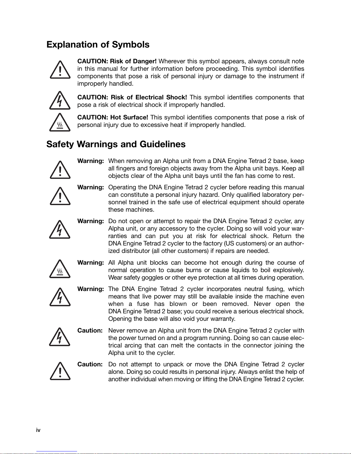
Explanation of Symbols
CAUTION: Risk of Danger! Wherever this symbol appears, always consult note
in this manual for further information before proceeding. This symbol identifies
components that pose a risk of personal injury or damage to the instrument if
improperly handled.
CAUTION: Risk of Electrical Shock! This symbol identifies components that
pose a risk of electrical shock if improperly handled.
CAUTION: Hot Surface! This symbol identifies components that pose a risk of
personal injury due to excessive heat if improperly handled.
Safety Warnings and Guidelines
Warning: When removing an Alpha unit from a DNA Engine Tetrad 2 base, keep
all fingers and foreign objects away from the Alpha unit bays. Keep all
objects clear of the Alpha unit bays until the fan has come to rest.
Warning: Operating the DNA Engine Tetrad 2 cycler before reading this manual
can constitute a personal injury hazard. Only qualified laboratory per-
sonnel trained in the safe use of electrical equipment should operate
these machines.
Warning: Do not open or attempt to repair the DNA Engine Tetrad 2 cycler, any
Alpha unit, or any accessory to the cycler. Doing so will void your war-
ranties and can put you at risk for electrical shock. Return the
DNA Engine Tetrad 2 cycler to the factory (US customers) or an author-
ized distributor (all other customers) if repairs are needed.
Warning: All Alpha unit blocks can become hot enough during the course of
normal operation to cause burns or cause liquids to boil explosively.
Wear safety goggles or other eye protection at all times during operation.
Warning: The DNA Engine Tetrad 2 cycler incorporates neutral fusing, which
means that live power may still be available inside the machine even
when a fuse has blown or been removed. Never open the
DNA Engine Tetrad 2 base; you could receive a serious electrical shock.
Opening the base will also void your warranty.
Caution: Never remove an Alpha unit from the DNA Engine Tetrad 2 cycler with
the power turned on and a program running. Doing so can cause elec-
trical arcing that can melt the contacts in the connector joining the
Alpha unit to the cycler.
Caution: Do not attempt to unpack or move the DNA Engine Tetrad 2 cycler
alone. Doing so could results in personal injury. Always enlist the help of
another individual when moving or lifting the DNA Engine Tetrad 2 cycler.
Page 6
Safe Use Guidelines
The DNA Engine Tetrad 2 cycler is designed to be safe to operate under the following
conditions:
• Indoor use
• Altitude up to 2000 m
• Ambient temperature 5–31°C
• Relative humidity 10–90%, noncondensing
• Transient overvoltage per Installation Category II, IEC 664
• Pollution degree 2, in accordance with IEC 664
Electromagnetic Interference
This device complies with Part 15 of the FCC Rules. Operation is subject to the
following two conditions: (1) this device may not cause harmful interference, and (2)
this device must accept any interference received, including interference that may
cause undesired operation.
This device has been tested and found to comply with the EMC standards for emissions
and susceptibility established by the European Union at time of manufacture.
This digital apparatus does not exceed the Class A limits for radio noise emissions
from digital apparatus set out in the Radio Interference Regulations of the Canadian
Department of Communications.
LE PRESENT APPAREIL NUMERIQUE N'EMET PAS DE BRUITS RADIOELEC-
TRIQUES DEPASSANT LES LIMITES APPLICABLES AUX APPAREILS NUMERIQUES
DE CLASS A PRESCRITES DANS LE REGLEMENT SUR LE BROUILLAGE RADIO-
ELECTRIQUE EDICTE PAR LE MINISTERE DES COMMUNICATIONS DU CANADA.
FCC Warning
Warning: Changes or modifications to this unit not expressly approved by the party
responsible for compliance could void the user’s authority to operate the equipment.
Note: This equipment has been tested and found to comply with the limits for a Class
A digital device, pursuant to Part 15 of the FCC Rules. These limits are designed to
provide reasonable protection against harmful interference when the equipment is
operated in a commercial environment. This equipment generates, uses, and can
radiate radiofrequency energy and, if not installed and used in accordance with the
instruction manual, may cause harmful interference to radio communications.
Operation of this equipment in a residential area is likely to cause harmful interference
in which case the user will be required to correct the interference at his own expense.
Shielded cables must be used with this unit to ensure compliance with the Class A
FCC limits.
Note Regarding FCC Compliance: Although this design of instrument has been tested and found to comply with Part
15, Subpart B of the FCC Rules for a Class A digital device, please note that this compliance is voluntary, for the
instrument qualifies as an "Exempted device" under 47 CFR § 15.103(c), in regard to the cited FCC regulations in
effect at the time of manufacture.
v
Page 7
vi
Documentation Conventions
Before describing the various features of the DNA Engine Tetrad 2 cycler, let’s define
some “common ground” conventions.
• << >> will be used to indicate actual keys on the control panel, such as
<<ENTER>>, <<1>> and <<LEFT>>.
• < > will be used to indicate windowed menu items or buttons, such as <PRO-
GRAMS>, <RUN> and <UTILITIES>.
• Italics will be used to indicate windowed items that are not drop down menu
items or buttons, such as Calculated, Block, and Tracking. Typically, these will be
parameter selection items.
• Select is meant to be synonymous with click on, point-and-click, and any
phraseology implying selection of menu or option items with the mouse. In some
instances, selection is also possible by clicking the <<Enter>> button.
___________________________________________________________________________
This instrument system is labeled, “For Research Use Only.”
Page 8
Introduction
1
Meet the DNA Engine Tetrad 2 Cycler . . . . . . . . . . . . . . . . . . . . . . . . . . . . . . . . . . . . . .1-2
Using This Manual . . . . . . . . . . . . . . . . . . . . . . . . . . . . . . . . . . . . . . . . . . . . . . . . . . . . . .1-2
Important Safety Information . . . . . . . . . . . . . . . . . . . . . . . . . . . . . . . . . . . . . . . . . . . . . .1-3
1-1
Page 9
DNA Engine Tetrad 2 Thermal Cycler Operations Manual
Meet the DNA Engine Tetrad®2 Cycler
Thank you for purchasing an DNA Engine Tetrad 2 cycler. Designed by a team of
molecular biologists and engineers, the DNA Engine Tetrad 2 cycler delivers multi-
block thermal cycling with superior thermal performance. The programmable
DNA Engine Tetrad 2 cycler with its 4-bay chassis is ideal for running multiple proto-
cols and accommodating multiple users.
The DNA Engine Tetrad 2 cycler offers the following features:
• Interchangeable sample blocks—the Alpha™unit family—accommodate a
variety of tubes, microplates, and slides
• Hot Bonnet®heated lid for oil-free cycling or the Moto Alpha™unit for auto-
mated systems
• Intuitive DNA Engine Tetrad 2 system software with user-friendly interface for
programming, editing, file management and much more
• Choice of calculated temperature control for highest speed and accuracy, or
of block or temperature control for compatibility with protocols designed for
a variety of instrument types
• Instant Incubate feature for continuous-temperature incubations
Using This Manual
This manual contains instructions for operating your DNA Engine Tetrad 2 cycler
safely and productively:
• Chapter 2 acquaints you with the physical characteristics of the
DNA Engine Tetrad 2 cycler.
• Chapters 3–4 present the basics of installation and operation for the
DNA Engine Tetrad 2 cycler.
• Chapters 5, 6 and 7 describe the creation, editing, and running of programs.
• Chapter 8 outlines the software utilities.
• Chapter 9 explains the proper maintenance of the DNA Engine Tetrad 2
cycler.
• Chapter 10 offers troubleshooting information for the DNA Engine Tetrad 2
cycler.
1-2 Tech Support: 1-800-4BIORAD • 1-800-424-6723 • www.bio-rad.com
Page 10
Important Safety Information
Safe operation of the DNA Engine Tetrad 2 cycler begins with a complete under-
standing of how the instrument works. Please read this entire manual before
attempting to operate the DNA Engine Tetrad cycler. Do not allow anyone who has
not read this manual to operate the instrument.
Warning: The DNA Engine Tetrad 2 cycler can generate enough heat to
inflict serious burns and can deliver strong electrical shocks if
not used according to the instructions in this manual. Please
read the safety warnings and guidelines at the beginning of
this manual on pages iv and v, and exercise all precautions
outlined in them.
Warning: Do not block the DNA Engine Tetrad 2 cycler’s air vents (see
figs. 2-1 and 2-4 for locations). Obstructing air vents can lead
to overheating and slightly enhanced risk of electrical shock
and fire.
Introduction
Tech Support: 1-800-4BIORAD • 1-800-424-6723 • www.bio-rad.com 1-3
Page 11

Page 12
Layout and
2
DNA Engine Tetrad 2 Cycler Front View . . . . . . . . . . . . . . . . . . . . . . . . . . . . . . . . . . . . .2-2
DNA Engine Tetrad 2 Cycler Control Panel . . . . . . . . . . . . . . . . . . . . . . . . . . . . . . . . . .2-2
DNA Engine Tetrad 2 Cycler Back View . . . . . . . . . . . . . . . . . . . . . . . . . . . . . . . . . . . . .2-3
DNA Engine Tetrad 2 Cycler Bottom View . . . . . . . . . . . . . . . . . . . . . . . . . . . . . . . . . . .2-3
Compatible Alpha Units . . . . . . . . . . . . . . . . . . . . . . . . . . . . . . . . . . . . . . . . . . . . . . . . . .2-4
DNA Engine Tetrad 2 Specifications . . . . . . . . . . . . . . . . . . . . . . . . . . . . . . . . . . . . . . . .2-5
Gradient Specifications (96-Well Alpha unit only) . . . . . . . . . . . . . . . . . . . . . . . . . . . . .2-5
Specifications
2-1
Page 13
DNA Engine Tetrad 2 Thermal Cycler Operations Manual
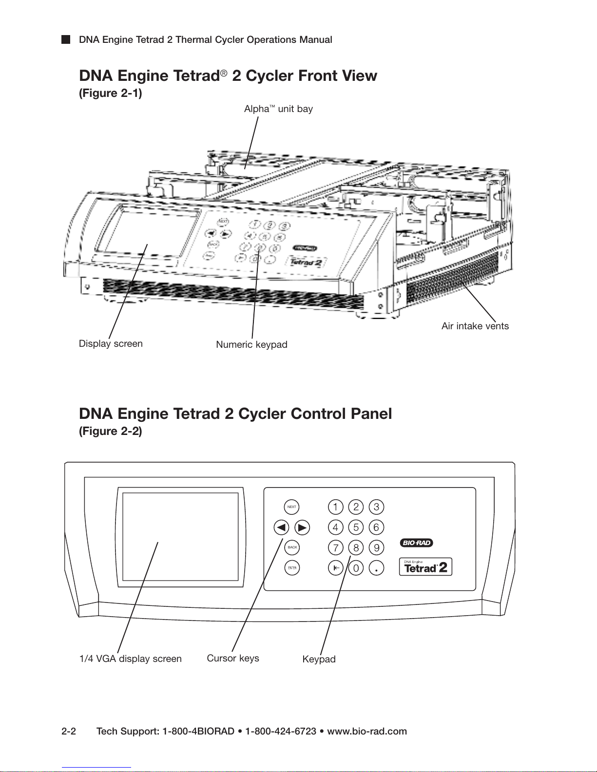
DNA Engine Tetrad®2 Cycler Front View
(Figure 2-1)
™
Alpha
NEXT
BACK
unit bay
Display screen
Numeric keypad
DNA Engine Tetrad 2 Cycler Control Panel
(Figure 2-2)
NEXT
BACK
Air intake vents
1/4 VGA display screen
2-2 Tech Support: 1-800-4BIORAD • 1-800-424-6723 • www.bio-rad.com
Cursor keys
Keypad
Page 14
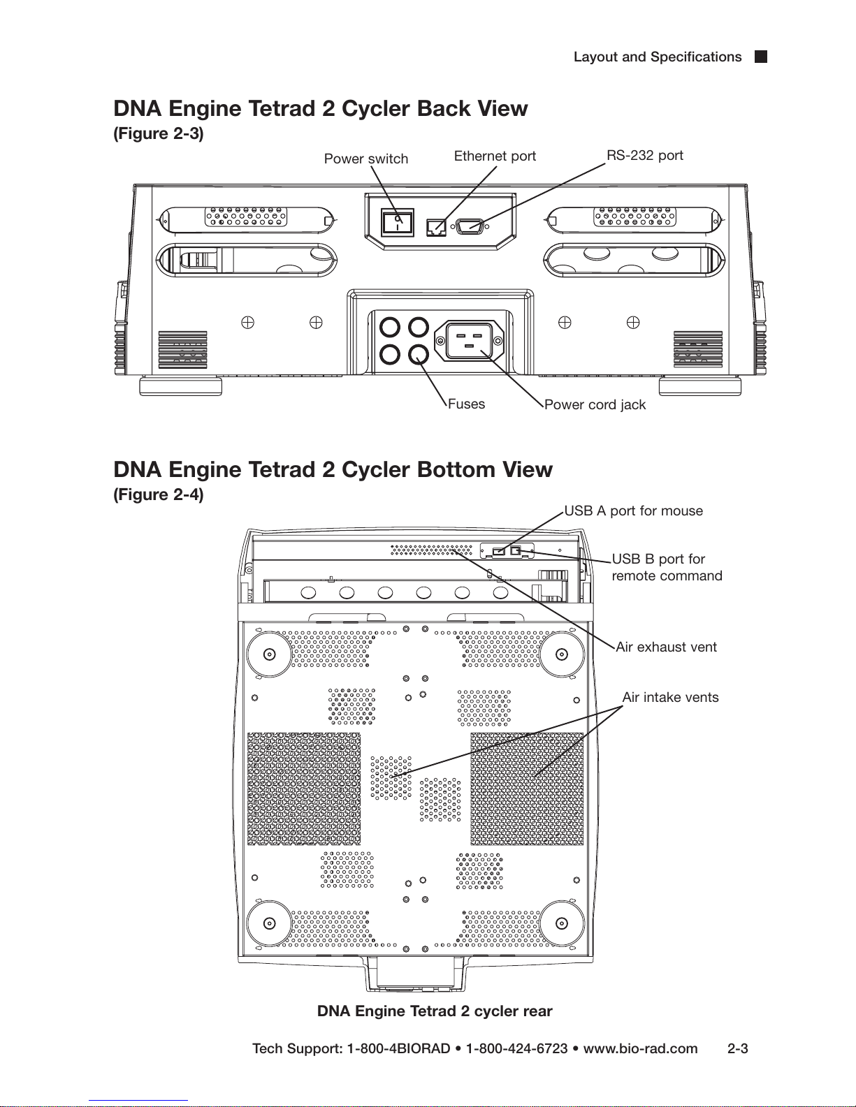
DNA Engine Tetrad 2 Cycler Back View
(Figure 2-3)
Power switch
Ethernet port
Layout and Specifications
RS-232 port
Fuses
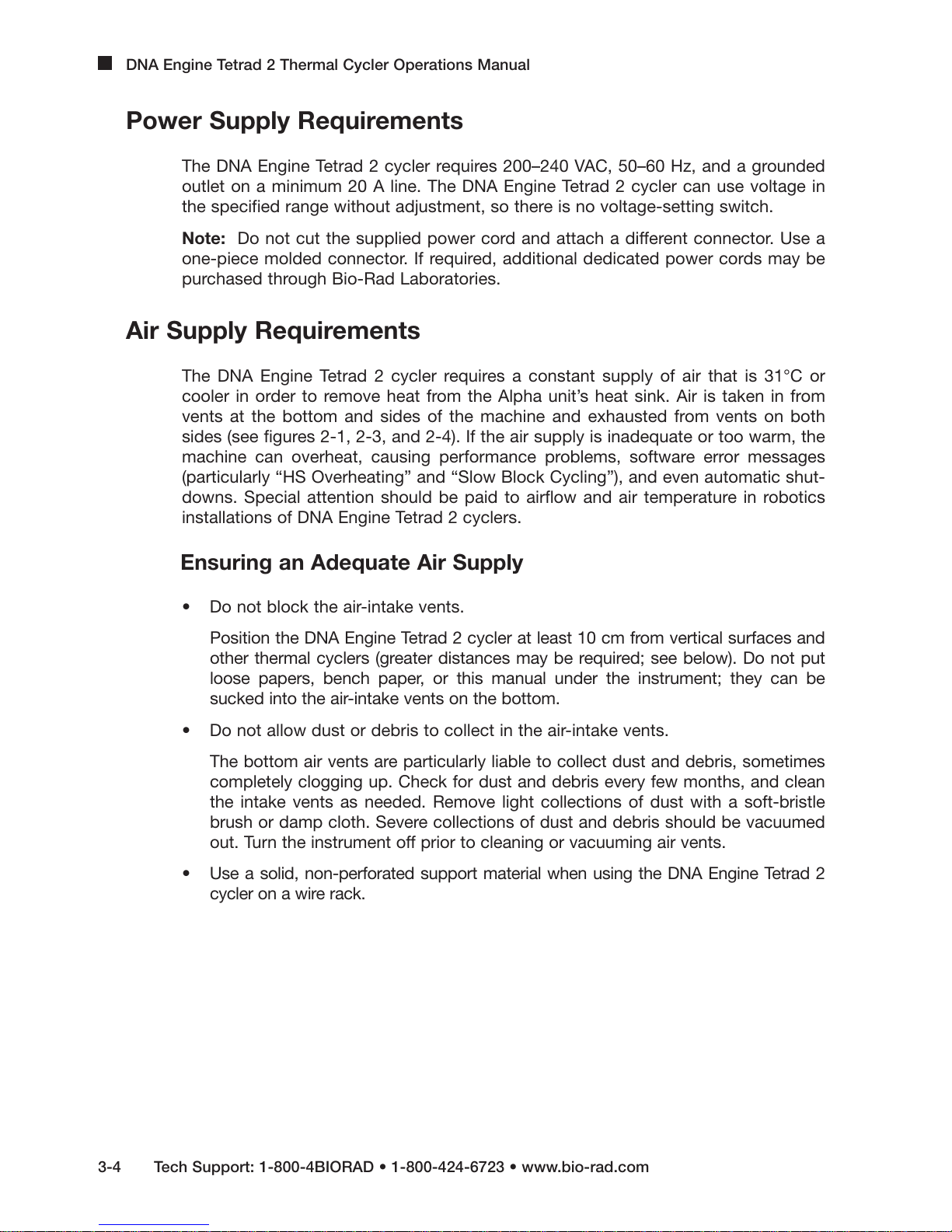
DNA Engine Tetrad 2 Cycler Bottom View
(Figure 2-4)
Power cord jack
USB A port for mouse
USB B port for
remote command
Air exhaust vent
Air intake vents
Tech Support: 1-800-4BIORAD • 1-800-424-6723 • www.bio-rad.com 2-3
DNA Engine Tetrad 2 cycler rear
Page 15
DNA Engine Tetrad 2 Thermal Cycler Operations Manual
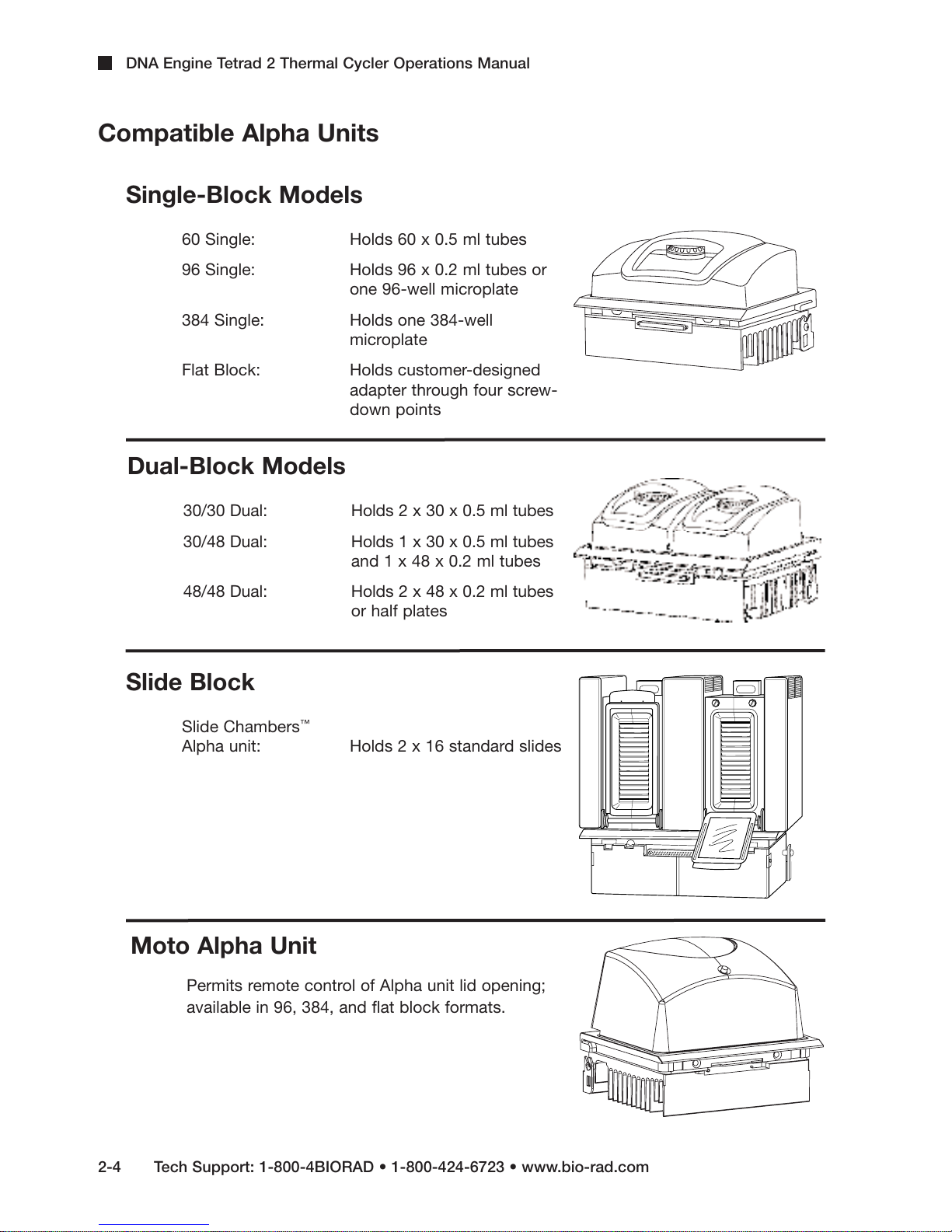
Compatible Alpha Units
Single-Block Models
60 Single: Holds 60 x 0.5 ml tubes
96 Single: Holds 96 x 0.2 ml tubes or
one 96-well microplate
384 Single: Holds one 384-well
microplate
Flat Block: Holds customer-designed
adapter through four screw-
down points
Dual-Block Models
30/30 Dual: Holds 2 x 30 x 0.5 ml tubes
30/48 Dual: Holds 1 x 30 x 0.5 ml tubes
48/48 Dual: Holds 2 x 48 x 0.2 ml tubes
Slide Block
Slide Chambers
Alpha unit: Holds 2 x 16 standard slides
Moto Alpha Unit
Permits remote control of Alpha unit lid opening;
available in 96, 384, and flat block formats.
and 1 x 48 x 0.2 ml tubes
or half plates
™
2-4 Tech Support: 1-800-4BIORAD • 1-800-424-6723 • www.bio-rad.com
Page 16
DNA Engine Tetrad 2 Specifications
Thermal range: 0–105°C, but no more than 30°C below ambient
temperature (10–105°C for the Slide Chambers unit)
Layout and Specifications
Temperature accuracy: +
Temperature uniformity: +
Speed of ramping: Up to 3°C/sec for all single- and dual-block Alpha units;
Sample capacity: Varies with installed Alpha unit
Line voltage: 200–240 VAC
Frequency: 50–60 Hz
Power: 1600 W maximum
Fuses: Two 6.3 A, 250 V, 5 x 20 mm
Displays: One 1/4 size VGA screen (320 x 240), 16 colors
Ports: One 9-pin RS-232 serial port
Program Capacity: 1,000 (typical)
Weight: 21.6 kg ( base only)
0.3°C of programmed target at 90°C, NIST-traceable
(+0.4°C for dual Alpha units)
0.4°C well-to-well within 30 seconds of arrival at
90°C (+0.5°C for dual Alpha units)
Up to 1.2°C/sec for the Slide Chambers Alpha unit
One ethernet port
Size: 47 x 61 x 16 cm (l x w x h, base only)
Projected Life Expectancy: 10 years of normal usage (2 protocol runs/day)
7 years of heavy usage (consistently exceeding
2 protocol runs/day)
Gradient Specifications (96-Well Alpha unit only)
Gradient accuracy: +
Column uniformity: +
Calculator accuracy: +
Lowest temperature 30°C
for gradient:
Highest temperature 105°C
for gradient:
Temperature differential 1–24°C
range:
0.3°C of programmed target at end columns,
30 seconds after the timer starts for the gradient step,
NIST–traceable
0.4°C, well–to–well within column, within 30 seconds
of reaching target temperature
0.4°C of actual well temperature, NIST-traceable
Tech Support: 1-800-4BIORAD • 1-800-424-6723 • www.bio-rad.com 2-5
Page 17

Page 18
Installation
3
Unpacking and Moving the DNA Engine Tetrad 2 Cycler . . . . . . . . . . . . . . . . . . . . . . .3-2
Packing Checklist . . . . . . . . . . . . . . . . . . . . . . . . . . . . . . . . . . . . . . . . . . . . . . . . . . . . . . .3-2
Setting Up the DNA Engine Tetrad 2 Cycler . . . . . . . . . . . . . . . . . . . . . . . . . . . . . . . . . .3-2
External Mouse Device . . . . . . . . . . . . . . . . . . . . . . . . . . . . . . . . . . . . . . . . . . . . . . . . . . .3-3
Environmental Requirements . . . . . . . . . . . . . . . . . . . . . . . . . . . . . . . . . . . . . . . . . . . . . .3-3
Power Supply Requirements . . . . . . . . . . . . . . . . . . . . . . . . . . . . . . . . . . . . . . . . . . . . . .3-4
Air Supply Requirements . . . . . . . . . . . . . . . . . . . . . . . . . . . . . . . . . . . . . . . . . . . . . . . . .3-4
Ensuring an Adequate Air Supply . . . . . . . . . . . . . . . . . . . . . . . . . . . . . . . . . . . . . .3-4
Ensuring That Air Is Cool Enough . . . . . . . . . . . . . . . . . . . . . . . . . . . . . . . . . . . . . .3-5
Requirements for Robotics Installations . . . . . . . . . . . . . . . . . . . . . . . . . . . . . . . . . . . .3-5
384-Well Microplate Specifics . . . . . . . . . . . . . . . . . . . . . . . . . . . . . . . . . . . . . . . . . . . . .3-6
3-1
Page 19
DNA Engine Tetrad 2 Thermal Cycler Operations Manual
Unpacking and Moving the DNA Engine Tetrad 2 Cycler
Please read the “Unpacking Instructions for the DNA Engine Tetrad®2 Thermal Cycler”
insert in order to properly and safely remove the instrument from its packaging. Always
enlist the help of another individual when moving or lifting the DNA Engine Tetrad 2 cycler.
In order to lift the instrument, grasp the DNA Engine Tetrad 2 cycler from underneath the
chassis (placing your hands on either side of the DNA Engine Tetrad 2 cycler in between
the feet of the instrument) and lift. Do not insert the Alpha™units until the instrument is
located in its final place.
Packing Checklist
After unpacking the DNA Engine Tetrad 2 cycler, check to see that you have received the
following:
• One DNA Engine Tetrad 2 base
• Four spare fuses
• One power cord
• One external mouse device
• DNA Engine Tetrad 2 Peltier Thermal Cycler Operations Manual (this
document)
• Unpacking Instructions for the DNA Engine Tetrad
If any of these components are missing or damaged, contact Bio-Rad Laboratories to
obtain a replacement. Please save the original packing materials in case you need to
return the DNA Engine Tetrad 2 cycler for service.
®
Setting Up the DNA Engine Tetrad 2 Cycler
The DNA Engine Tetrad 2 cycler requires only minimal assembly, plugging in the power
cord and mounting the Alpha units. Insert the power cord plug into its jack at the back of
the machine (see figure 2-3 for location of jack), then plug the cord into a 220 V electrical
outlet. With the machine switched off, mount the Alpha units (see the “Installing an Alpha unit”
section in Chapter 4).
Caution: Do not insert or remove an Alpha unit with the DNA Engine Tetrad 2
cycler turned on; electrical arcing can result. Read the safety warning at the
beginning of this manual on page iv regarding electrical safety when inserting
or removing an Alpha unit.
2 Thermal Cycler
3-2 Tech Support: 1-800-4BIORAD • 1-800-424-6723 • www.bio-rad.com
Page 20
External Mouse Device
Included with each shipment of a DNA Engine Tetrad 2 thermal cycler is an externally
attachable mouse, which should be attached prior to power up of the
DNA Engine Tetrad 2 cycler. Usage of the mouse is required to access full function-
ality of the programming software. Underneath the front lip of the DNA Engine Tetrad
2 cycler are two connection ports (see figure 2-4). The mouse should be connected
to the USB A port.To ensure complete compliance with FCC and EMC requirements,
only a mouse with a ferrite core should be used with the DNA Engine Tetrad 2 instru-
ment.
To connect the mouse, please follow these steps:
1. Verify that the DNA Engine Tetrad 2 cycler is off. Wait for 10 seconds to ensure
that all fans have stopped rotating.
2. Grasping the sides of the DNA Engine Tetrad 2 cycler, tilt the instrument back so
that the underside of the lip is visible.
3. Insert the mouse into the USB A port and push the connector into place.
Installation
4. Tip the DNA Engine Tetrad 2 cycler back down and power up the system.
Environmental Requirements
Ensure that the area where the DNA Engine Tetrad 2 cycler is installed meets the
following conditions, for reasons of safety and performance:
• Nonexplosive environment
• Normal air pressure (altitude below 2000 m)
• Ambient temperature 5–31°C
• Relative humidity of 10–90% (noncondensing)
• Unobstructed access to air that is 31°C or cooler (see below)
• Protection from excessive heat and accidental spills. (Do not place the
DNA Engine Tetrad 2 cycler near such heat sources as radiators, and protect it from
danger of having water or other fluids splashed on it, which can cause shorting of its
electrical circuits.)
Tech Support: 1-800-4BIORAD • 1-800-424-6723 • www.bio-rad.com 3-3
Page 21
DNA Engine Tetrad 2 Thermal Cycler Operations Manual
Power Supply Requirements
The DNA Engine Tetrad 2 cycler requires 200–240 VAC, 50–60 Hz, and a grounded
outlet on a minimum 20 A line. The DNA Engine Tetrad 2 cycler can use voltage in
the specified range without adjustment, so there is no voltage-setting switch.
Note: Do not cut the supplied power cord and attach a different connector. Use a
one-piece molded connector. If required, additional dedicated power cords may be
purchased through Bio-Rad Laboratories.
Air Supply Requirements
The DNA Engine Tetrad 2 cycler requires a constant supply of air that is 31°C or
cooler in order to remove heat from the Alpha unit’s heat sink. Air is taken in from
vents at the bottom and sides of the machine and exhausted from vents on both
sides (see figures 2-1, 2-3, and 2-4). If the air supply is inadequate or too warm, the
machine can overheat, causing performance problems, software error messages
(particularly “HS Overheating” and “Slow Block Cycling”), and even automatic shut-
downs. Special attention should be paid to airflow and air temperature in robotics
installations of DNA Engine Tetrad 2 cyclers.
Ensuring an Adequate Air Supply
• Do not block the air-intake vents.
Position the DNA Engine Tetrad 2 cycler at least 10 cm from vertical surfaces and
other thermal cyclers (greater distances may be required; see below). Do not put
loose papers, bench paper, or this manual under the instrument; they can be
sucked into the air-intake vents on the bottom.
• Do not allow dust or debris to collect in the air-intake vents.
The bottom air vents are particularly liable to collect dust and debris, sometimes
completely clogging up. Check for dust and debris every few months, and clean
the intake vents as needed. Remove light collections of dust with a soft-bristle
brush or damp cloth. Severe collections of dust and debris should be vacuumed
out. Turn the instrument off prior to cleaning or vacuuming air vents.
• Use a solid, non-perforated support material when using the DNA Engine Tetrad 2
cycler on a wire rack.
3-4 Tech Support: 1-800-4BIORAD • 1-800-424-6723 • www.bio-rad.com
Page 22
Installation
Cause Possible Remedies
Air circulation is poor. Provide more space around machine or adjust room
ventilation.
Ambient air temperature is high. Adjust air conditioning to lower ambient air temperature.
Machine is in warm part of room. Move machine away from, or protect machine from, such
heat sources as radiators, heaters, other equipment, or
bright sunlight.
Machines are crowded. Arrange machines so that warm exhaust air does not enter
intake vents.
Ensuring That Air Is Cool Enough
• Do not position two or more DNA Engine Tetrad 2 cyclers (or other thermal cyclers)
so that the hot exhaust air of one blows directly into the air-intake vents of another.
• Make sure the DNA Engine Tetrad 2 cycler receives air that is 31°C or cooler by measuring
the temperature of air entering the machine through its air-intake vents.
Place the DNA Engine Tetrad 2 cycler where you plan to use it and turn it on. Try to
reproduce what will be typical operating conditions for the machine in that location,
particularly any heat-producing factors (e.g., nearby equipment running, window
blinds open, lights on). Run a typical protocol for 30 minutes to warm up the
DNA Engine Tetrad 2 cycler, then measure the air temperature at the back air-intake
vents. If more than one machine is involved, measure the air temperature for each. If
the air-intake temperature of any machine is warmer than 31°C, use Table 3-1 to trou-
bleshoot the problem. Some experimentation may be required to determine the best
solution when more than one cause is involved. After taking steps to solve the
problem, verify that the temperature of the air entering the air-intake vents has been
lowered, using the procedure outlined above.
Requirements for Robotics Installations
Robotics installations require special attention to airflow and air temperature. Typically in
these installations, DNA Engine Tetrad 2 cyclers and other thermal cyclers are restricted to
a small area, along with other heat-generating equipment. Overheating can quickly occur
when many of these instruments are operating at once, unless preventive measures are
taken.
Follow the procedures described above to ensure adequate airflow and an air-intake
temperature of 31°C or cooler. Air-intake temperature must be verified by measurement.
Do not use oil or glycerin to thermally couple sample vessels to the blocks of machines in
a robotics installation. This can make plates difficult to remove.
Tech Support: 1-800-4BIORAD • 1-800-424-6723 • www.bio-rad.com 3-5
Page 23
DNA Engine Tetrad 2 Thermal Cycler Operations Manual
384-Well Microplate Specifics
Some users find that a 384-well microplate can be difficult to remove from the 384-well
block after completing their thermal cycling protocol. The plate fits very snugly in the block,
and the 384 points of contact can provide a significant amount of friction. Fortunately, it is
relatively simple to ameliorate this problem if it occurs in your application.
In our experience, a very thin coating of a Teflon-based dry lubricant sprayed onto the
block will solve the sticking problem very effectively. The coating eventually wears off so
the block should be re-coated as needed, probably about once every 10 to 20 runs. Your
experience will be the best guide in establishing the frequency for re-coating. As you will
see, a very thin coat is sufficient to eliminate any sticking.
TFE (tetra-fluoroethylene) dry lubricant is available from many sources. One source in the
United States is:
Miller-Stephenson Chemical Co., Inc.
in Danbury, CT: 203-743-4447
in Morton Grove, IL: 847-966-2022
in Sylmar, CA: 818-896-4714
TFE Dry Lubricant/Release Agent
Cat.# MS-122DF (aerosol, 10 oz can) approx. $10.50/can
Here are some guidelines for applying the TFE lubricant:
1. Cool the block and lid to room temperature (below 38°C).
2. Cover the lid and any other areas that you don’t want to get slippery.
3. Shake the can well.
4. Spray for about 1 second onto the block.
3-6 Tech Support: 1-800-4BIORAD • 1-800-424-6723 • www.bio-rad.com
Page 24
Operation
4
Turning the DNA Engine Tetrad 2 Cycler On . . . . . . . . . . . . . . . . . . . . . . . . . . . . . . . . . 4-2
Using the Control Panel . . . . . . . . . . . . . . . . . . . . . . . . . . . . . . . . . . . . . . . . . . . . . . . . . 4-3
Display Screen . . . . . . . . . . . . . . . . . . . . . . . . . . . . . . . . . . . . . . . . . . . . . . . . . . . . 4-3
Operation Keys . . . . . . . . . . . . . . . . . . . . . . . . . . . . . . . . . . . . . . . . . . . . . . . . . . . . 4-3
Block Status Lights . . . . . . . . . . . . . . . . . . . . . . . . . . . . . . . . . . . . . . . . . . . . . . . . 4-4
Using the Data Ports . . . . . . . . . . . . . . . . . . . . . . . . . . . . . . . . . . . . . . . . . . . . . . . . . . . . 4-4
Operating Alpha Units . . . . . . . . . . . . . . . . . . . . . . . . . . . . . . . . . . . . . . . . . . . . . . . . . . . 4-4
Installing an Alpha Unit . . . . . . . . . . . . . . . . . . . . . . . . . . . . . . . . . . . . . . . . . . . . . 4-4
Removing an Alpha Unit . . . . . . . . . . . . . . . . . . . . . . . . . . . . . . . . . . . . . . . . . . . . 4-5
Opening an Alpha Unit . . . . . . . . . . . . . . . . . . . . . . . . . . . . . . . . . . . . . . . . . . . . . . 4-6
Closing an Alpha Unit . . . . . . . . . . . . . . . . . . . . . . . . . . . . . . . . . . . . . . . . . . . . . . 4-6
Selecting the Correct Sample Vessel . . . . . . . . . . . . . . . . . . . . . . . . . . . . . . . . . . . . . . 4-6
0.5 ml Tubes . . . . . . . . . . . . . . . . . . . . . . . . . . . . . . . . . . . . . . . . . . . . . . . . . . . . . . 4-7
Thin-Walled vs. Thick-Walled Tubes . . . . . . . . . . . . . . . . . . . . . . . . . . . . . . . . . . . 4-7
0.2 ml Tubes . . . . . . . . . . . . . . . . . . . . . . . . . . . . . . . . . . . . . . . . . . . . . . . . . . . . . . 4-7
Microplates . . . . . . . . . . . . . . . . . . . . . . . . . . . . . . . . . . . . . . . . . . . . . . . . . . . . . . . 4-7
Sealing Sample Vessels . . . . . . . . . . . . . . . . . . . . . . . . . . . . . . . . . . . . . . . . . . . . . . . . . . 4-8
Sealing with Oil or Wax . . . . . . . . . . . . . . . . . . . . . . . . . . . . . . . . . . . . . . . . . . . . . 4-8
Sealing with the Hot Bonnet Lid . . . . . . . . . . . . . . . . . . . . . . . . . . . . . . . . . . . . . . 4-8
Adjusting the Hot Bonnet Lid’s Pressure . . . . . . . . . . . . . . . . . . . . . . . . . . 4-9
Loading Sample Vessels into the Block . . . . . . . . . . . . . . . . . . . . . . . . . . . . . . . . . . . 4-10
Using Oil to Thermally Couple Sample Vessels to the Block . . . . . . . . . . . . . . . 4-10
Appendix 4-A: Tube, Microplate, and Sealing System Selection Chart . . . . . . . . . . 4-12
Appendix 4-B: Safety Warning Regarding Use of 35S Nucleotides . . . . . . . . . . . . . 4-13
4-1
Page 25
DNA Engine Tetrad 2 Thermal Cycler Operations Manual
Turning the DNA Engine Tetrad®2 Cycler On
Caution: Do not insert or remove an Alpha™unit with the DNA Engine Tetrad 2
cycler turned on; electrical arcing can result. Read the safety warning
regarding electrical safety on page iv of this manual before inserting or
removing an Alpha unit or operating the DNA Engine Tetrad 2 cycler.
The Alpha units must be installed prior to powering up the DNA Engine Tetrad 2
cycler (see the "Operating Alpha Units" section below for installation instructions).
The power switch is located at the back of the instrument (see figure 2-3). Turn the
power switch on. The fan will turn on, the display screen will illuminate, and the
microprocessor will implement a boot-up protocol lasting about 1 minute, 30 sec-
onds. During the boot sequence, the user is presented with several options including:
1. Selftest — Choose number 1 on the keypad to instruct the DNA Engine Tetrad 2
cycler to perform a diagnostic system test and report any errors.
2. Send Files — Choose number 2 on the keypad to prepare the cycler to transfer
stored program files to another DNA Engine Tetrad 2 cycler (see Chapter 8 for
instructions on transferring program files).
3. Receive Files — Choose number 3 on the keypad to prepare the cycler to receive
stored program files from another DNA Engine Tetrad 2 cycler (see Chapter 8 for
instructions on transferring program files).
If no option is selected, the boot sequence will automatically exit after approximately
six seconds.
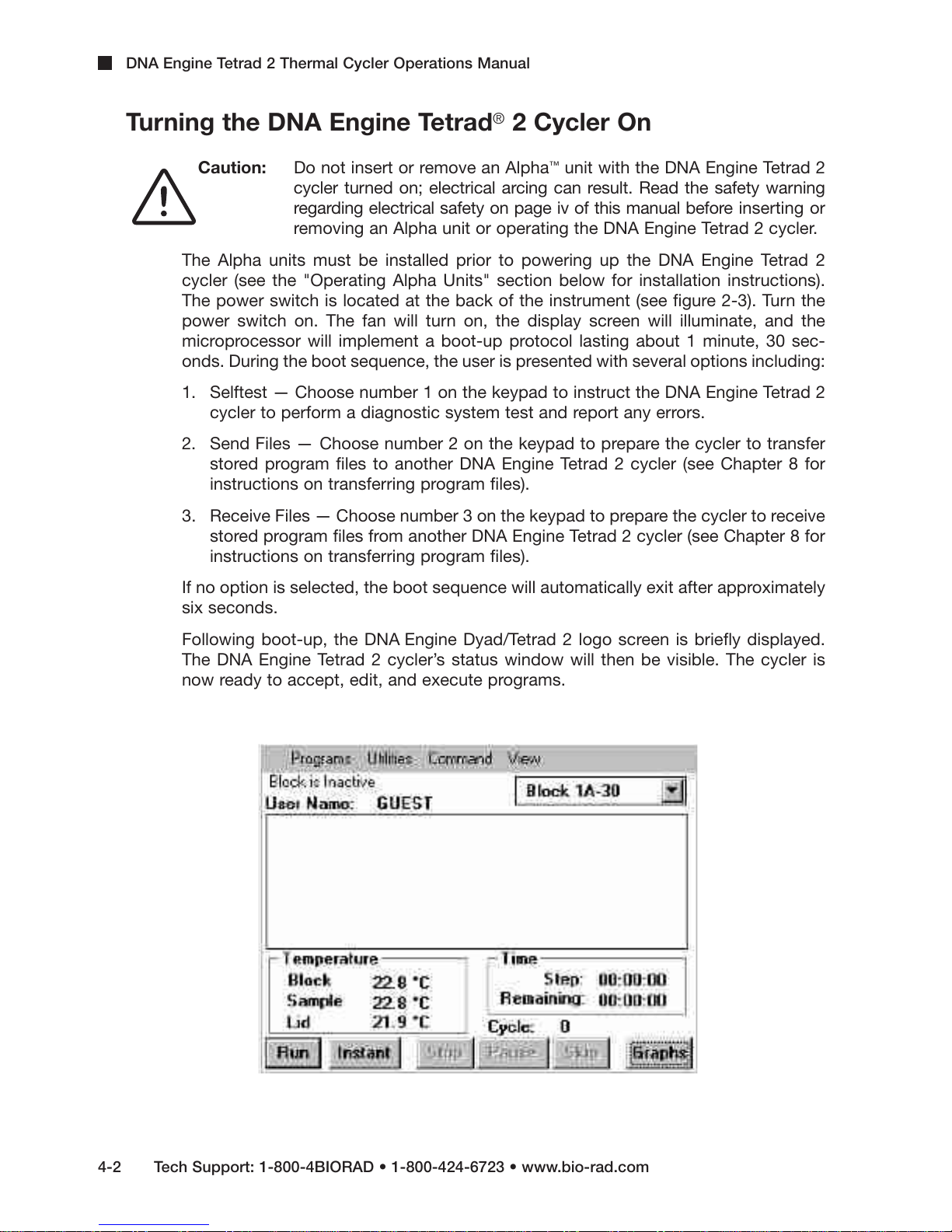
Following boot-up, the DNA Engine Dyad/Tetrad 2 logo screen is briefly displayed.
The DNA Engine Tetrad 2 cycler’s status window will then be visible. The cycler is
now ready to accept, edit, and execute programs.
4-2 Tech Support: 1-800-4BIORAD • 1-800-424-6723 • www.bio-rad.com
Page 26
Using the Control Panel
The control panel (see figure 2-2) includes: a display screen, cursor keys, a numeric
keypad, and enter key.
Display Screen
• The display screen is a 1/4 size VGA screen for displaying thermal cycler condi-
tions and programs.
Operation Keys
• Navigation keys (left and right arrows, next, back) — Use to move around
within the display screen.
• Numeric keypad — Use to enter numeric values.
• Enter key — Use to accept specific programming additions and modifications.
Operation
Note: The external mouse is used to execute selected commands, access menus,
and to toggle through selection options in a list.
Tech Support: 1-800-4BIORAD • 1-800-424-6723 • www.bio-rad.com 4-3
Page 27
DNA Engine Tetrad 2 Thermal Cycler Operations Manual
Block Status Lights
• When illuminated, these blue lights indicate whether the left and/or right Alpha
units are in use.
Using the Data Ports
The DNA Engine Tetrad 2 cycler has two data ports located at the rear of the machine —
an RS-232 port and an Ethernet port. See Chapter 8 for information on using these ports.
Operating Alpha Units
Note: Operation of the Slide Chambers™Alpha unit will not be discussed, owing to the
many differences between this type of Alpha unit and the others. Please see the
Slide Chambers Alpha Unit Operations Manual for operating instructions.
Note: Moto Alpha units are installed and removed as described below. See the Moto Alpha
Unit User’s Manual and "The Moto Alpha Unit" section in Chapter 5 for information on
opening and closing Moto Alpha units.
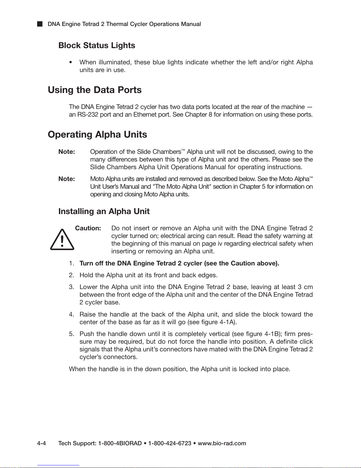
Installing an Alpha Unit
Caution: Do not insert or remove an Alpha unit with the DNA Engine Tetrad 2
cycler turned on; electrical arcing can result. Read the safety warning at
the beginning of this manual on page iv regarding electrical safety when
inserting or removing an Alpha unit.
1. Turn off the DNA Engine Tetrad 2 cycler (see the Caution above).
2. Hold the Alpha unit at its front and back edges.
3. Lower the Alpha unit into the DNA Engine Tetrad 2 base, leaving at least 3 cm
between the front edge of the Alpha unit and the center of the DNA Engine Tetrad
2 cycler base.
4. Raise the handle at the back of the Alpha unit, and slide the block toward the
center of the base as far as it will go (see figure 4-1A).
5. Push the handle down until it is completely vertical (see figure 4-1B); firm pres-
sure may be required, but do not force the handle into position. A definite click
signals that the Alpha unit’s connectors have mated with the DNA Engine Tetrad 2
cycler’s connectors.
™
When the handle is in the down position, the Alpha unit is locked into place.
4-4 Tech Support: 1-800-4BIORAD • 1-800-424-6723 • www.bio-rad.com
Page 28

Operation
Removing an Alpha Unit
Caution: Do not insert or remove an Alpha unit with the DNA Engine Tetrad 2
cycler turned on; electrical arcing can result. Read the safety warning at
the beginning of this manual on page iv regarding electrical safety when
inserting or removing an Alpha unit.
1. Turn off the DNA Engine Tetrad 2 cycler (see the Caution above).
2. Pull upward on the handle. When the lock releases, you will hear a click, and the
Alpha unit will slide a little outward from the center of the cycler. The electrical
connectors of the Alpha unit and the DNA Engine Tetrad 2 cycler are now disen-
gaged, and there is little danger of electrical shock.
3. Slide the Alpha unit from the center of the DNA Engine Tetrad 2 base, about 3 cm.
4. Grasp the front and back edges of the Alpha unit, and lift it out of the machine.
Figure 4-1 Installing an Alpha unit (as shown on a DNA Engine Dyad®thermal cycler).
A
B
Tech Support: 1-800-4BIORAD • 1-800-424-6723 • www.bio-rad.com 4-5
Page 29
DNA Engine Tetrad 2 Thermal Cycler Operations Manual
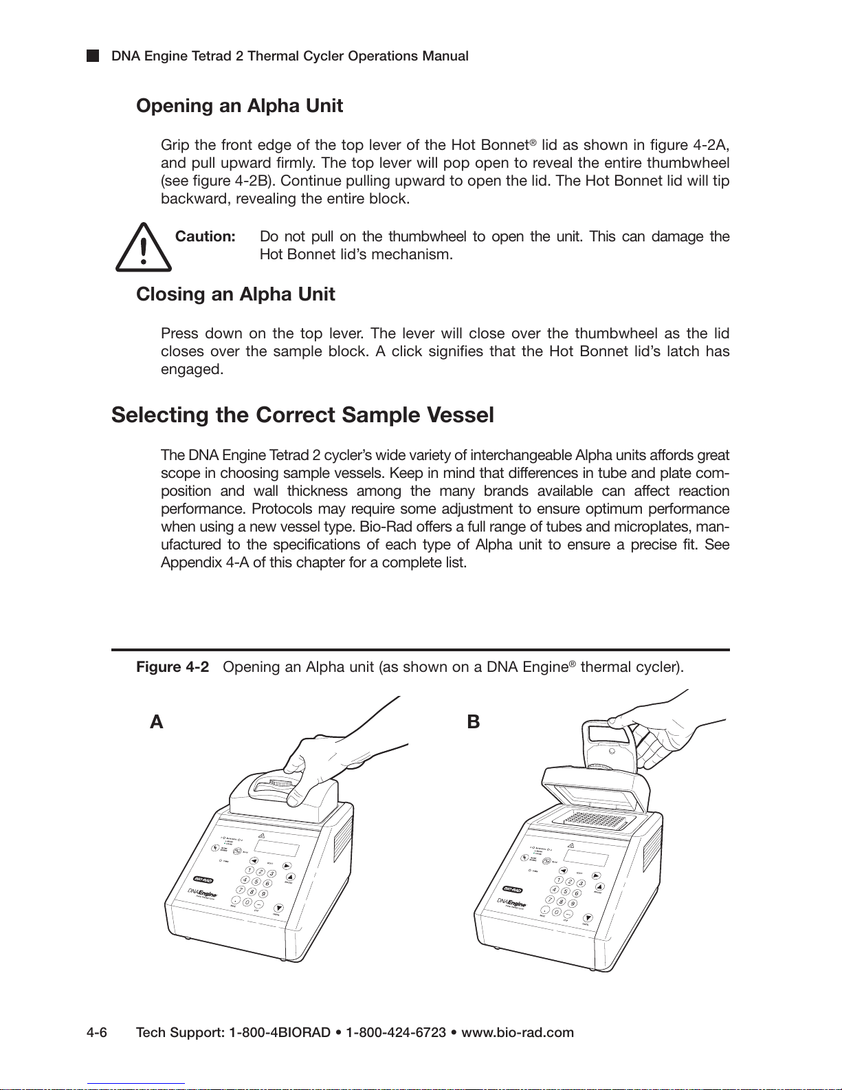
Opening an Alpha Unit
Grip the front edge of the top lever of the Hot Bonnet®lid as shown in figure 4-2A,
and pull upward firmly. The top lever will pop open to reveal the entire thumbwheel
(see figure 4-2B). Continue pulling upward to open the lid. The Hot Bonnet lid will tip
backward, revealing the entire block.
Caution: Do not pull on the thumbwheel to open the unit. This can damage the
Hot Bonnet lid’s mechanism.
Closing an Alpha Unit
Press down on the top lever. The lever will close over the thumbwheel as the lid
closes over the sample block. A click signifies that the Hot Bonnet lid’s latch has
engaged.
Selecting the Correct Sample Vessel
The DNA Engine Tetrad 2 cycler’s wide variety of interchangeable Alpha units affords great
scope in choosing sample vessels. Keep in mind that differences in tube and plate com-
position and wall thickness among the many brands available can affect reaction
performance. Protocols may require some adjustment to ensure optimum performance
when using a new vessel type. Bio-Rad offers a full range of tubes and microplates, man-
ufactured to the specifications of each type of Alpha unit to ensure a precise fit. See
Appendix 4-A of this chapter for a complete list.
Figure 4-2 Opening an Alpha unit (as shown on a DNA Engine®thermal cycler).
A
B
4-6 Tech Support: 1-800-4BIORAD • 1-800-424-6723 • www.bio-rad.com
Page 30
Operation
0.5 ml Tubes
Thick-walled 0.5 ml tubes may not fit tightly in thermal cycler wells and typically provide
poor thermal transfer, since these tubes were originally designed for centrifuges. For
best results, we recommend using thin-walled 0.5 ml tubes specifically designed for
thermal cycling. The higher quality brands provide a good and consistent fit. Bio-Rad
thin-walled 0.5 ml tubes are designed for precise block fit and tight sealing of reactions
down to 10 µl.
Thin-Walled vs. Thick-Walled Tubes
The thickness of sample tubes directly affects the speed of sample heating and thus
the amount of time required for incubations. Thick-walled tubes delay sample
heating, since heat transfers more slowly through the tubes’ walls. For the earliest
types of thermal cyclers, this delay mattered little. These machines’ ramping rates
were so slow (below 1°C/sec) that there was plenty of time for heat to transfer
through the tube wall to the sample, during a given incubation.
Modern thermal cyclers have much faster ramping rates (up to 2–3°C/second), so the
faster heat transfer provided by thin-walled tubes allows protocols to be significantly
shortened.
0.2 ml Tubes
All types of thin-walled 0.2 ml tubes may be used. Bio-Rad offers high-quality 0.2 ml
tubes in a number of styles, including individual and strip tubes.
Microplates
A variety of polycarbonate or polypropylene microplates can be used in Alpha units
as long as they fit the wells snugly. Polypropylene microplates are usually preferred
because they exhibit very low protein binding and, unlike polycarbonate microplates,
do not lose water vapor through the vessel walls. This allows smaller sample volumes
to be used—as little as 5–10 µl.
Several varieties of microplates are available from Bio-Rad (see the "Tube, Microplate,
and Sealing Selection Chart"), including Hard-Shell®thin-wall microplates. Hard-
Shell microplates feature a skirt and deck molded from a rigid, thermostable polymer
that completely resists the warping and shrinkage experienced with traditional one-
component plates. The rigid skirt improves robotic handling such that stackers and
robotic arms can grip and move Hard-Shell plates securely and reliably. In a separate
step, thin-wall wells are molded of virgin polypropylene selected for low DNA binding
and optimized for thermal cycling.
Tech Support: 1-800-4BIORAD • 1-800-424-6723 • www.bio-rad.com 4-7
Page 31

DNA Engine Tetrad 2 Thermal Cycler Operations Manual
Sealing Sample Vessels
To avoid changing the concentration of reactants, steps must be taken to prevent the
evaporation of water from reaction mixtures during thermal cycling. Only a layer of oil or
wax will completely prevent evaporation from the surface of the reaction fluid. However, an
adequate degree of protection can be achieved by sealing vessels with caps, film, adhesive
seals, or mats, then cycling the samples using the heated lid to prevent condensation.
Sealing with Oil or Wax
Mineral oil, silicone oil, paraffin wax, or Chill-out™liquid wax may be used to seal sam-
ples. Use only a small amount of oil or wax; 1–3 drops (15–50 µl) are usually sufficient.
(Include this volume in the total volume when setting up a calculated-control protocol;
see “Choosing a Temperature Control Mode” in Chapter 5.) Use the same amount of
oil or wax in all sample vessels to ensure a uniform thermal profile.
Most paraffin waxes solidify at room temperature. The wax can then be pierced with a
micropipette tip and the samples drawn off from below the wax. Silicone oil and mineral
oil can be poured off or aspirated from tubes if the samples are first frozen (–15° to –20°C).
The samples are usually pure enough for analysis without an extraction.
Chill-out liquid wax (available from Bio-Rad) is an easy-to-use alternative to oil. This puri-
fied paraffinic oil solidifies at 14°C and is liquid at room temperature. By programming a
hold at low temperature, the wax can be solidified at the end of a run. A pipette tip can
then be used to pierce the wax in the tubes and remove the samples. The wax is available
in a clear, optical-assay grade or dyed red to assist in monitoring its use. The red dye has
no adverse effects on fluorescent gel analysis of reaction products.
Sealing with the Hot Bonnet Lid
The Hot Bonnet’s heated inner lid maintains the air in the upper part of sample ves-
sels at a higher temperature than the reaction mixture. This prevents condensation of
evaporated water vapor onto the vessel walls and lid, so that solution concentrations
are unchanged by thermal cycling. The Hot Bonnet lid also exerts pressure on the
tops of vessels loaded into the block, helping to maintain a vapor-tight seal and to
firmly seat tubes or the plate in the block.
Caps, film, adhesive seals, or mats must be used along with the Hot Bonnet lid to
prevent evaporative losses.
Note: When tubes are cooled to below-ambient temperatures, a ring of condensa-
tion may form in tubes above the liquid level but below the top of the sample block.
This is not a cause for concern since it occurs only at the final cool-down step, when
thermal cycling is complete.
Microseal®'A' film offers a quick alternative to sealing microplates or arrays of tube strips.
This film is specially designed to seal tightly during cycling, yet release smoothly to
minimize the risk of aerosol formation and cross-contamination of samples.
Microseal 'A' film is easily cut for use with fewer than 96 samples.
4-8 Tech Support: 1-800-4BIORAD • 1-800-424-6723 • www.bio-rad.com
Page 32

Operation
Microseal 'B' adhesive seals feature an aggressive adhesive, effective from –20°C to
110°C, which allows secure sample storage or transport before and after cycling. The clear
polyester backing allows easy inspection of sample wells. Microseal 'B' clear, adhesive
seals are ideal for thermal cycling in all polypropylene and polystyrene microplates.
Microseal 'F' aluminized foil acts as a barrier against evaporation from –20°C to
105°C. In addition to cold storage applications, it can also be used for thermal cycling
sample volumes >
25 µl (96-well) or >5 µl (384-well). The foil is thin enough to pierce
with a pipet tip for recovery of sample from individual wells.
Microplate sealing mats are an economical means to seal 96-well microplates. An array
of 96 dimples on the mat helps orient it on the microplate and prevents the mat from
sticking to the heated lid. The mats may be cleaned with sodium hypochlorite (bleach) for
reuse, and they are autoclavable.
Microseal 'P' and 'P+' sealing pads are designed for use in applications such as cycle
sequencing in which several successive runs may be sealed with the same pad.
Microseal 'P' and 'P+' pads are intended for use with the higher sealing pressures
afforded by the Power Alpha units: use 'P' pads with the original version of Power
Bonnet™lids (ALP-1296 and ALP-1238) and 'P+' pads with newer-design Moto Alpha
units (ALP-2296 and ALP-2238). Each pad may be used for approximately 25 runs.
Adjusting the Hot Bonnet Lid’s Pressure
The pressure exerted by the Hot Bonnet lid must be manually adjusted to fit the
sample vessels being used. Once set, the Hot Bonnet lid can be opened and
closed repeatedly without readjustment as long as neither the tube or microplate
type nor the sealing method is changed. Any change in vessel type or sealing
method requires readjustment of the Hot Bonnet lid.
Follow these steps to adjust the pressure exerted by the inner lid:
1. Make sure the block’s wells are clean. Even tiny amounts of extraneous material
can decrease thermal conduction and interfere with the proper seating of a
microplate or tubes.
2. Open the Hot Bonnet lid. Turn the thumbwheel all the way counterclockwise
to completely raise the inner lid.
3. Load either a microplate or at least eight individual tubes into the sample block.
The inner lid pivots around a central point, so it is important to distribute individual
tubes evenly: load at least four tubes in the center of the block and at least one
tube in each of the four corners of the block. If using a sealing film or mat, apply
it to the loaded microplate according to the manufacturer’s directions.
4. Close the Hot Bonnet lid by pressing down on the top lever. Turn the thumb-
wheel clockwise to lower the inner lid onto the loaded microplate/tubes.
The thumbwheel turns easily at first since the inner lid has not yet come into
contact with anything. Stop turning the thumbwheel when you feel
increased resistance, which indicates that the inner lid has touched the
microplate/tubes.
Tech Support: 1-800-4BIORAD • 1-800-424-6723 • www.bio-rad.com 4-9
Page 33

DNA Engine Tetrad 2 Thermal Cycler Operations Manual
5. For microplate sealing films or mats that require additional pressure, turn the
thumbwheel clockwise an extra half turn past the point of initial contact to set
an appropriate lid pressure.
Caution: Do not turn the thumbwheel more than three-quarters of a turn. This can
make it hard or impossible to close the lid and puts excessive strain on
the latch holding the lid closed.
An extra half to three-quarters of a turn ensures the correct pressure for most
types of reaction vessels. Some empirical testing may be required to deter-
mine the optimum pressure required for certain vessels. Once this pressure
has been determined, the thumbwheel position may be marked with a col-
ored marking pen or piece of tape.
Note: As an aid in gauging how much the thumbwheel has been turned, mark it at the
quarter turn positions, or every sixth “bump” on the thumbwheel (there are 24 total “bumps”).
Loading Sample Vessels into the Block
When using a small number of tubes, load at least one empty tube in each corner of
the block to ensure that the Hot Bonnet lid exerts even pressure on the sample tubes
(see “Adjusting the Hot Bonnet Lid’s Pressure,” above).
To ensure uniform heating and cooling of samples, sample vessels must be in complete
contact with the block. Adequate contact is ensured by always doing the following:
• Ensure that the block is clean before loading samples (see Chapter 9 for cleaning
instructions).
• Firmly press individual tubes or the microplate into the block wells.
Using Oil to Thermally Couple Sample Vessels to the Block
With two exceptions (see below), Bio-Rad Laboratories does not recommend using
oil to thermally couple sample vessels to the block, for the following reasons:
• Calculated-control protocols do not run accurately when oil is used.
• Oil traps dirt, which interferes with thermal contact between vessels and the block.
4-10 Tech Support: 1-800-4BIORAD • 1-800-424-6723 • www.bio-rad.com
Page 34

Operation
Caution: If you use oil in the block, use only mineral oil. Never use silicone oil.
It can damage the Alpha unit.
One exception to this recommendation involves the use of volatile radioactive 35S
nucleotides. A small amount of oil in the block can help prevent escape of these
compounds. See Appendix 4-B of this chapter for important information regarding
safe use of these compounds in polypropylene tubes and polypropylene and poly-
carbonate microplates. A second exception involves the use of thick-wall 0.5 ml
tubes. Certain brands of these tubes fit poorly in the block, in which case, oil may
somewhat improve thermal contact. Whenever possible, use high-quality thin-wall
tubes intended for thermal cycling (see Appendix 4-A of this chapter for a tube and
plate selection chart).
Tech Support: 1-800-4BIORAD • 1-800-424-6723 • www.bio-rad.com 4-11
Page 35

DNA Engine Tetrad 2 Thermal Cycler Operations Manual
Bio-Rad Thermal
Cycler Blocks
Reaction Vessels Sealing Options for Oil-Free Cycling
48369
)lm2.0(
84
)lm2.0(
03/06
)lm5.0(
noitpircseD Bio-Rad
#golataC
laesorciM
mlif'A'
1005-ASM
laesorciM
laes'B'
1001-BSM
laesorciM
liof'F'
1001-FSM
oplaterciM
tasealing m
223-9442
laesorciM
dap'P'
1001-PSM
laesorciM
**dap'+P'
2001-PSM
pirtS
spac
-SCTseires
tuo-llihC
xaw
seires-OHC
llehS-draH
setalporcimllew-483
seires-PSH
laesorcMi skirted
setalporcimllew-483
seires-PSM
detriksllehS-draH
setalporcimllew-69
seires-PSH
detrikslaesorciM
setalporcimllew-69
seires-PSM
etalpitluM
™
detriksnu
setalporcimllew-69
seires-PLM
seires-LLM
detriksnuetalpitluM
setalporcimllew-84
seires-PLM
detriksnuetalpitluM
setalporcimllew-52
1052-PLM
detriksnuetalpitluM
setalporcimllew-42
1042-PLM
drocnoC
™
detriks
detriks
*setalporcimllew-69
1069-NOC
sebutpirtslm2.0
pirts/21&pirts/8
seires-SBT
seires-SLT
laudividnilm2.0
sebu
t
1020-IFT
1020-IWT
seires-IBT
laudividnilm5.0
spac/w,sebu
t
seires-IBT
Appendix 4-A Tube, Microplate, and Sealing
System Selection Chart
The following sample vessels and sealing options are recommended for use with the
DNA Engine Tetrad 2 cycler and are available from Bio-Rad.
Key
4 Reaction vessel fits block/sealing option fits reaction vessel without modification.
# Reaction vessel/sealing option can be cut to fit.
4-12 Tech Support: 1-800-4BIORAD • 1-800-424-6723 • www.bio-rad.com
* "Concord" microplates are made from polycarbonate plastic, which is prone to poor sealing and
vapor leakage during stringent thermal cycling.
** Since plates may adhere tightly to the Microseal 'P+' pad, this seal is only recommended for use
with the Moto Alpha™motorized unit, which has the ability to hold the plate in the block.
Page 36

Appendix 4-B Safety Warning Regarding
Use of 35S Nucleotides
Some researchers have experienced a problem with radioactive contamination when
using 35S in thermal cyclers. This problem has occurred with all types of reaction vessels.
The Problem
When 35S nucleotides are thermally cycled, a volatile chemical breakdown product forms,
probably SO2. This product can escape the vessel and contaminate the sample block of
a thermal cycler, and possibly, the air in the laboratory. Contamination has been reported
with microassay plates, 0.2 ml tubes, and 0.5 ml tubes.
96-Well Polycarbonate Microplates
These microplates present the largest risk of contamination. Polycarbonate is
somewhat permeable both to water and the 35S breakdown product. This problem
is exacerbated when polycarbonate plates are held at high temperatures for long
periods of time, or when the plates are sealed for oil-free thermal cycling.
Operation
0.2 ml Polypropylene Tubes and Polypropylene Microplates
These tubes are manufactured with very thin walls to enhance thermal transfer. The
thin walls are somewhat fragile and can “craze” or develop small cracks when
subject to mechanical stress. Undamaged thin polypropylene tubes may also be
somewhat permeable to the
reports of 35S passing through the walls of 0.2 ml tubes of several different brands
during thermal cycling. No data are yet available on radioactive contamination
with polypropylene microplates.
35
S breakdown product. Either way, there have been
0.5 ml Polypropylene Tubes
Contamination problems are rarer with this type of tube, but instances have been
reported.
Tech Support: 1-800-4BIORAD • 1-800-424-6723 • www.bio-rad.com 4-13
Page 37

DNA Engine Tetrad 2 Thermal Cycler Operations Manual
The Solution
1. Substitute the low-energy beta emitter 33P in cycle sequencing. 33P nucleotides
are not subject to the same kind of chemical breakdown as 35S nucleotides, and
they have not been associated with volatile breakdown products.
2. If 35S must be used, three things will help control contamination: an oil overlay
inside the tubes, mineral oil in the thermal cycler outside the tubes, and use of
thick-walled 0.5 ml tubes. Always run 35S thermal cycling reactions in a fume
hood, and be aware that vessels may be contaminated on the outside after
thermal cycling. Please be certain that you are using the appropriate detection
methods and cleaning procedures for this isotope. Consult your radiation safety
officer for his or her recommendations.
If mild cleaning agents do not remove radioactivity, harsher cleaners may be used
occasionally and carefully. Users have suggested the detergent PCC-54 (Pierce
Chemical Co., Rockford, Illinois; Pierce Eurochemie B.V., Holland), Micro Cleaning
Solution (Cole-Parmer, Niles, Illinois), and Dow Bathroom Cleaner (available in
supermarkets).
Caution: Harsh cleaning agents (such as those above) are corrosive and must be
thoroughly rinsed away within a few minutes of application. They can eat
away the surface finish of the blocks.
4-14 Tech Support: 1-800-4BIORAD • 1-800-424-6723 • www.bio-rad.com
Page 38

Creating Programs
5
Front Panel Setup . . . . . . . . . . . . . . . . . . . . . . . . . . . . . . . . . . . . . . . . . . . . . . . . . . . . . . .5-3
Display Screen . . . . . . . . . . . . . . . . . . . . . . . . . . . . . . . . . . . . . . . . . . . . . . . . . . . .5-3
Navigation Keys . . . . . . . . . . . . . . . . . . . . . . . . . . . . . . . . . . . . . . . . . . . . . . . . . . .5-3
Numeric Keypad . . . . . . . . . . . . . . . . . . . . . . . . . . . . . . . . . . . . . . . . . . . . . . . . . . .5-4
Programming Conventions . . . . . . . . . . . . . . . . . . . . . . . . . . . . . . . . . . . . . . . . . . . . . . .5-4
The Elements of a Program . . . . . . . . . . . . . . . . . . . . . . . . . . . . . . . . . . . . . . . . . . . . . . .5-4
Types of Programs . . . . . . . . . . . . . . . . . . . . . . . . . . . . . . . . . . . . . . . . . . . . . . . . . . . . . .5-6
Graphical Programs . . . . . . . . . . . . . . . . . . . . . . . . . . . . . . . . . . . . . . . . . . . . . . . .5-6
Advanced Programs . . . . . . . . . . . . . . . . . . . . . . . . . . . . . . . . . . . . . . . . . . . . . . . .5-7
Designing a New Program . . . . . . . . . . . . . . . . . . . . . . . . . . . . . . . . . . . . . . . . . . . . . . . .5-7
Let’s Start with an Example . . . . . . . . . . . . . . . . . . . . . . . . . . . . . . . . . . . . . . . . . .5-8
The Goto Option . . . . . . . . . . . . . . . . . . . . . . . . . . . . . . . . . . . . . . . . . . . . . . . . . . .5-8
Considerations During Program Creation . . . . . . . . . . . . . . . . . . . . . . . . . . . . . . . . . . .5-9
Choosing a Temperature Control Mode . . . . . . . . . . . . . . . . . . . . . . . . . . . . . . . . .5-9
Calculated Control . . . . . . . . . . . . . . . . . . . . . . . . . . . . . . . . . . . . . . . . . . . .5-9
Block Control . . . . . . . . . . . . . . . . . . . . . . . . . . . . . . . . . . . . . . . . . . . . . . .5-10
Modifying Block-Control Programs for Calculated Control . . . . . . . . . . .5-10
Modifying a Program Designed for a Different Machine . . . . . . . . . . . . . .5-10
Choosing a Lid Control Mode . . . . . . . . . . . . . . . . . . . . . . . . . . . . . . . . . . . . . . . .5-11
Choosing a Temperature Ramping Rate . . . . . . . . . . . . . . . . . . . . . . . . . . . . . . .5-11
Choosing a Temperature Hold Time . . . . . . . . . . . . . . . . . . . . . . . . . . . . . . . . . . .5-11
Choosing a Thermal Gradient . . . . . . . . . . . . . . . . . . . . . . . . . . . . . . . . . . . . . . . .5-12
Beyond the Example Protocol: Other Considerations . . . . . . . . . . . . . . . . . . . . .5-13
5-1
Page 39

DNA Engine Tetrad 2 Thermal Cycler Operations Manual
Entering Program Steps . . . . . . . . . . . . . . . . . . . . . . . . . . . . . . . . . . . . . . . . . . . . . . . . .5-14
The Status Window . . . . . . . . . . . . . . . . . . . . . . . . . . . . . . . . . . . . . . . . . . . . . . . .5-14
Entering a Program Using Graphical Mode . . . . . . . . . . . . . . . . . . . . . . . . . . . . .5-15
Using the Mode Selection Window . . . . . . . . . . . . . . . . . . . . . . . . . . . . . .5-16
Using the File Save As Window . . . . . . . . . . . . . . . . . . . . . . . . . . . . . . . .5-17
Folder Passwords . . . . . . . . . . . . . . . . . . . . . . . . . . . . . . . . . . . . . . . . . . .5-19
The Graphical Programming Window . . . . . . . . . . . . . . . . . . . . . . . . . . . .5-20
Selecting a Step . . . . . . . . . . . . . . . . . . . . . . . . . . . . . . . . . . . . . .5-20
Editing Step Parameters . . . . . . . . . . . . . . . . . . . . . . . . . . . . . . . .5-20
Deleting a Step . . . . . . . . . . . . . . . . . . . . . . . . . . . . . . . . . . . . . . .5-21
Adding a Step . . . . . . . . . . . . . . . . . . . . . . . . . . . . . . . . . . . . . . . .5-21
Entering a Temperature Step . . . . . . . . . . . . . . . . . . . . . . . . . . . . . . . . . . .5-21
Entering a Gradient Step . . . . . . . . . . . . . . . . . . . . . . . . . . . . . . . . . . . . . .5-24
Entering a Goto Step . . . . . . . . . . . . . . . . . . . . . . . . . . . . . . . . . . . . . . . . .5-25
Entering a Forever Incubation . . . . . . . . . . . . . . . . . . . . . . . . . . . . . . . . . .5-26
Entering a Program Using Advanced Mode . . . . . . . . . . . . . . . . . . . . . . . . . . . . .5-27
Entering a Temperature Step . . . . . . . . . . . . . . . . . . . . . . . . . . . . . . . . . . . . . . . .5-28
Entering a Gradient Step . . . . . . . . . . . . . . . . . . . . . . . . . . . . . . . . . . . . . .5-31
The Extend Time Option . . . . . . . . . . . . . . . . . . . . . . . . . . . . . . . . . . . . . .5-33
Entering a Goto Step . . . . . . . . . . . . . . . . . . . . . . . . . . . . . . . . . . . . . . . . .5-34
Entering a Lid Control Step . . . . . . . . . . . . . . . . . . . . . . . . . . . . . . . . . . . .5-35
The Slow Ramp Option . . . . . . . . . . . . . . . . . . . . . . . . . . . . . . . . . . . . . . .5-35
The Increment Temp Option . . . . . . . . . . . . . . . . . . . . . . . . . . . . . . . . . . .5-36
The Moto Alpha Unit . . . . . . . . . . . . . . . . . . . . . . . . . . . . . . . . . . . . . . . . . . . . . . . . . . . .5-38
5-2 Tech Support: 1-800-4BIORAD • 1-800-424-6723 • www.bio-rad.com
Page 40

The DNA Engine Tetrad®cycler comes with several preprogrammed thermal cycling
protocols. These protocols are listed in Appendix C. This chapter describes how to
create your own protocols, while the next chapter describes how to modify both the
preprogrammed protocols and any you create yourself. In this chapter, we revisit the
setup of the front panel, specifically those items used in program input. We describe the
conventions used, as well as the various programming steps and what they accomplish.
We make suggestions regarding the translation of a cycle sequencing protocol into a
Tetrad™2 program. Finally, we use a cycle-sequencing example to illustrate the pro-
gramming process step by step. This manual documents version 4.00 of the
DNA Engine Tetrad 2 front-end software.
Front Panel Setup
The various components of the DNA Engine Tetrad 2 cycler’s control panel (see figure 2-2)
allow the operator to enter, navigate, and manipulate programs. These programs are nec-
essary to control the various dynamic capabilities of the DNA Engine Tetrad 2 cycler.
Note: Chapter 4 covers the basic operation of the DNA Engine Tetrad 2 cycler. Please read
Chapter 4 for a complete description of the control panel and power-up procedures.
Let’s review. The control panel components include:
Creating Programs
Display Screen
This is a 1/4 VGA display screen, approximately 10 cm x 12.5 cm, located at the left side of
the control panel. It displays all DNA Engine Tetrad 2 cycler operating parameters, and can
be controlled by the cursor buttons, external mouse, and the numeric keypad.
Navigation Keys
There are four navigation keys located to the right of the display screen. They can be
used to navigate through various menu and selection items.
The use of these keys is optional as ALL screen selections can be done using the
external mouse device.
The next/back keys are primarily used to move through all available buttons or
options in any given window. The left/right keys are used to navigate through menu
bars.
Tech Support: 1-800-4BIORAD • 1-800-424-6723 • www.bio-rad.com 5-3
Page 41

DNA Engine Tetrad 2 Thermal Cycler Operations Manual
Enter Key
This is located below the navigation keys and is used to accept specific program-
ming additions and modifications.
Note: The external mouse is used to execute selected commands, access menus,
and to toggle through selection options in a list.
Numeric Keypad
This is located to the right of the navigation buttons and consists of a typical numeric
keypad (numbers 0–9). There is also a backspace/delete key and a decimal button.
The numeric keypad is used to enter parameters such as temperature, hold time, and
cycle iterations.
Programming Conventions
Before starting the programming process, let’s review the conventions used here.
• << >> will be used to indicate actual keys on the control panel, such as
<<ENTER>>, <<1>>, and <<LEFT>>.
• < > will be used to indicate windowed menu items or buttons, such as <PROGRAMS>,
<RUN> and <UTILITIES>.
• Italics will be used to indicate windowed items that are not drop-down menu
items or buttons, such as Calculated, Block, and Tracking. Typically, these will be
parameter selection items.
• Select is meant to be synonymous with click on, point-and-click, and any phrase-
ology implying selection of menu or option items with the mouse.
The Elements of a Program
Tetrad 2 programs consist of a combination or series of steps and setup parameters
that represent protocol requirements.
Note: The procedures involved in actually entering these steps will be described in sub-
sequent pages, but please familiarize yourself with the types of steps used to create
Tetrad 2 programs.
The considerations behind choosing various elements will be explained further in the
“Considerations During Program Creation” section. The following is a summary of the
individual program elements and their basic functions.
5-4 Tech Support: 1-800-4BIORAD • 1-800-424-6723 • www.bio-rad.com
Page 42

Creating Programs
Temperature Control Mode: This parameter defines the temperature control
algorithm used during the program run. The three different modes include
Calculated and Block. Due to the expected lag of sample temperature behind
block temperature, the DNA Engine Tetrad 2 cycler can use calculated mode to
compensate accordingly. The cycler defaults to Calculated mode. Refer to the
section “Choosing a Temperature Control Mode” below for additional information.
Lid Control Mode: The Hot Bonnet®heated lid can be programmed to minimize
condensation by keeping the upper surface of the reaction vessel at a temperature
slightly greater than that of the sample itself. The three available lid modes include
Off, Tracking, and Constant. The DNA Engine Tetrad 2 cycler defaults to
Constant. Refer to the “Choosing a Lid Control Mode” section below for addi-
tional information.
Temperature step: This sets incubation temperature and duration. The
DNA Engine Tetrad 2 cycler ramps the sample to this temperature at its maximum rate
unless ramp modifying instructions are added to the program (advanced mode only).
The maximum rate of heating is 3°C/sec and cooling is 2°C/sec for all standard Alpha
units (maximum rate of heating is 1.2°C/sec for the Slide Chambers™Alpha unit).
Gradient step: This establishes a temperature gradient across a 96-well sample
block. The range of any single gradient can be as great as 24°C or as small as 1°C
from left to right across the block. The maximum programmable temperature is 105°C;
the minimum programmable temperature is 30°C.
™
GoTo step: Directs the program to cycle back to an earlier step a specified
number of times.
Lid step: Directs a Moto Alpha™unit to automatically open or close (only available
in advanced programs).
End step: Automatically included, this instructs the DNA Engine Tetrad 2 cycler
to shut down its heat pump because the program is complete.
Additional program modifications are available with advanced programs (see the
“Types of Programs” section immediately following for more information on
advanced programs):
1. Increment Temp: Modifies a temperature step to allow a “per cycle” increase
or decrease of temperature (0.1°C to 10.0°C per cycle) each time the step is
executed. This feature is useful when annealing stringency is a consideration
such as in a touchdown program.
In a touchdown program, the annealing temperature begins higher than the cal-
culated temperature, and incrementally decreases each cycle, first reaching, and
eventually falling below the calculated annealing temperature. With the reaction
beginning at a temperature favoring high stringency in hybridization and incre-
menting to lower stringency, the reaction favors the desired product by creating
a high proportion of signal relative to noise in the early amplification cycles.
2. Extend Time: Modifies a temperature step to allow a “per cycle” lengthening or
shortening of a temperature step hold (by 1–60 sec/cycle) each time a step is exe-
cuted. This capability is useful for slowly increasing (typically by 2 to 5 seconds
per cycle) the hold time during an extension step. The number of bases that a
Tech Support: 1-800-4BIORAD • 1-800-424-6723 • www.bio-rad.com 5-5
Page 43

DNA Engine Tetrad 2 Thermal Cycler Operations Manual
polymerase must synthesize during the extension step increases in later cycles
because there are more template molecules, because there are fewer active poly-
merase molecules, or both. The extra time can allow synthesis to be completed.
3. Slow Ramp: Temperature modification which allows for slower temperature
ramping than the default maximum rate of 3.0°C/sec. The minimum rate cur-
rently allowed is 0.1°C/sec. Slower ramp times than this may be achieved using
a combination of increment and goto steps. Contact Bio-Rad Technical Support
for details.
4. Beep: Modifies a temperature step or ramp step so the instrument will beep
when the target temperature is reached.
Types of Programs
There are two types of Tetrad 2 programs, basic and advanced. Basic programming fea-
tures a graphical interface and a graphical representation of the program steps.
Advanced programming features a text-based interface and a descriptive listing of the
program steps.
Basic program Advanced program
Graphical Programs
Creating a basic (graphical) program is desirable if you prefer the graphical program-
ming interface and/or wish to quickly enter a program that:
• Does not contain more than a total of six temperature and/or gradient steps.
• Does not contain temperature or gradient steps that contain modifications
(i.e., increment temp, extend time, slow ramp, beep).
• Does not contain more than one goto step.
• Does not contain a temperature incubation below 0°C.
• Does not contain a step with an incubation lasting more than 1 hour 39 minutes
and 59 seconds (99:59). Forever incubations excepted.
5-6 Tech Support: 1-800-4BIORAD • 1-800-424-6723 • www.bio-rad.com
Page 44

Creating Programs
In addition to the speed with which they can be entered, another benefit of graphical
programs is that they can be quickly edited. This can be particularly useful if you tend
to repeatedly run the same general protocol with limited changes (e.g., varying
annealing temperatures).
Advanced Programs
Advanced programs offer all of the Tetrad 2 programming features with the excep-
tion of the graphical programming interface. Creating an advanced program is
desirable if you wish to enter a program that:
• Contains many steps.
• Contains temperature or gradient steps with modifying instructions (i.e., increment
temp, extend time, slow ramp, beep).
• Contains multiple goto steps.
• Contains a temperature incubation in the range of –1°C to –5°C.
• Contains an incubation lasting between 1 hour 40 minutes and 18 hours (incubation
times shorter than 1 hour 40 minutes and forever incubations are also allowed.)
While all graphical programs can be opened and edited in advanced mode, only a
subset of advanced programs can be opened and edited in basic mode. Advanced
programs that meet the criteria outlined above for graphical programs can be opened
in basic mode (see “Opening a Program” in Chapter 6 for more information).
Designing a New Program
The first step in designing any program is the translation of your experimental
protocol into Tetrad 2 program steps. We suggest writing all steps until you are rea-
sonably comfortable with Tetrad 2 programming.
For purposes of this explanation, we will be working with a cycle sequencing
example. First, we will write down the raw steps, then make some modifications with
the parameters that were described in a previous section (“The Elements of a
Program”) and then determine what our final program should be. The actual
implementation and entering of program steps will be covered in a later section.
Note: You will soon become familiar with Tetrad 2 program design and be able to
enter steps directly from experimental protocols. However, we strongly suggest
following these steps the first few times through, as they will probably save trou-
bleshooting time later.
Tech Support: 1-800-4BIORAD • 1-800-424-6723 • www.bio-rad.com 5-7
Page 45

DNA Engine Tetrad 2 Thermal Cycler Operations Manual
Example Program
Let’s start with an example. Assume you have the necessary components for a 30-cycle
amplification reaction, and you have calculated the annealing temperature of your oligonu-
cleotide to be 60°C. Please note that we recommend using 92°C as the default
denaturation temperature during cycling steps. The resulting raw program you write may
look something like this:
Raw program:
1. 92°C for 30 seconds
2. 60°C for 3 minutes
3. 92°C for 30 seconds
4. 60°C for 3 minutes
5. 92°C for 30 seconds
6. 60°C for 3 minutes
[continues for a total of 60 lines]
The Goto Option
At 60 lines, our program is large, unwieldy and would take time to input. At step 3,
repetition can be reduced with the addition of a goto statement:
Raw program:
1. 92°C for 30 seconds
2. 60°C for 3 minutes
3. Goto step 1, 29 more times
4. END
One of the most important factors in the program writing process is identifying repetitive
steps. These can then be enclosed in a goto loop as shown above.
5-8 Tech Support: 1-800-4BIORAD • 1-800-424-6723 • www.bio-rad.com
Page 46

Considerations During Program Creation
Once you have written the body of your raw program, there are decisions to make
before creating your Tetrad 2 program. They concern how your steps should be
implemented. These decisions involve the following:
• Temperature control mode
• Lid control mode
• Temperature ramping rate (advanced mode only)
• Temperature hold time
• Temperature time extend (advanced mode only)
• Temperature increment (advanced mode only)
• Temperature gradient (available with the 96-well Alpha unit only)
• Outside of the example protocol: other considerations
Choosing a Temperature Control Mode
Creating Programs
The DNA Engine Tetrad 2 cycler can control incubation temperature in two possible
ways, each of which has different implications for the speed and accuracy of sample
heating. These include Calculated Control and Block Control.
Calculated Control
When using calculated control, the DNA Engine Tetrad 2 cycler estimates sample tem-
peratures based on the block’s thermal profile, the rate of heat transfer through the
sample tube or slide, and the sample volume or mass. Since this estimate is based on
known quantities and the laws of thermodynamics, sample temperatures are controlled
much more accurately than with block control.
Since the sample temperature will always lag behind the block temperature, the
DNA Engine Tetrad 2 cycler can adjust the block temperature to bring samples of a
specific volume in a specific vessel type to programmed temperatures. This is done
through optimized overshoots of the block temperature by a few degrees for a few
seconds, which bring samples to the desired temperature more quickly.
Tech Support: 1-800-4BIORAD • 1-800-424-6723 • www.bio-rad.com 5-9
Page 47

DNA Engine Tetrad 2 Thermal Cycler Operations Manual
Calculated control is also the method of choice for most types of programs because
it yields the most consistency, reliability, and speed. Calculated control provides for
shorter protocols in three ways:
1. Brief and precise block temperature overshoots are used to bring samples to
the desired incubation temperature rapidly.
2. Incubation periods are timed according to how long the samples, not the
blocks, reside at the target temperature.
3. The instrument automatically compensates for vessel type and reaction volume.
Note: We will choose calculated control for our example.
Block Control
The DNA Engine Tetrad 2 cycler maintains the block at the programmed temperature,
independent of sample temperature. This mode of temperature control is common to
older models of thermal cyclers.
Block control provides less accurate control of sample temperatures than calculated con-
trol provides. Under block control, the temperature of samples will lag behind the
temperature of the block. The length of the time lag depends on the vessel type and
sample volume but typically is between 10 and 30 seconds. Block control is chiefly used
to run protocols developed for other thermal cyclers that use block control, or if you use
the <Instant> command to incubate samples at a set temperature for long periods of time.
Modifying Block-Control Programs for Calculated Control
Block-control programs can be changed to calculated control by subtracting at least
15–20 seconds from each temperature step. Some empirical testing may be required to
adjust modified programs for optimum performance. We generally recommend not
reducing the incubation time for a step below 5 seconds while in calculated control mode.
Modifying a Program Designed for a Different Machine
The ramp programming step can be used to adapt programs designed for thermal
cyclers with slower maximum heating and cooling rates than the DNA Engine Tetrad 2
cycler. In addition, a given protocol will occasionally work better with a slower rate of
temperature change; the ramp step can be used to optimize the program for such a
protocol.
5-10 Tech Support: 1-800-4BIORAD • 1-800-424-6723 • www.bio-rad.com
Page 48

Creating Programs
Choosing a Lid Control Mode
When a sample is heated, condensation on the tube cap or plate cover can take place.
This changes the volume of the sample, the concentration of components, and the
kinetics of the enzymatic reaction. The Hot Bonnet heated lid minimizes condensation
by heating the upper surface of the reaction vessel to a temperature slightly greater
than that of the sample itself. The DNA Engine Tetrad 2 cycler can control lid temper-
ature in three possible ways: Constant, Tracking, or Off.
Constant Mode: This mode maintains the inner lid surface at a specific temper-
ature regardless of sample temperature. When using constant mode, specify a lid
temperature at least 5°C higher than any temperature used in the protocol.
Note: We will choose to maintain a constant lid temperature of 100°C in our
example program.
Tracking Mode: This mode incorproates a temperature offset of the heated inner
lid by a minimum specified number of degrees Celsius in comparison to the
temperature of the sample block. Tracking is useful for protocols with long
incubations in the range of 30–70°C, where it may be undesirable to keep the lid
at a very high temperature. An offset of 5°C above block temperature is adequate
for most protocols.
Off: No power is applied to the heated lid. In this mode, condensation will occur
at a rate consistent with the incubation temperature and the type of tube or plate
sealant being used. This option is recommended only when using an oil or wax
overlay.
Choosing a Temperature Ramping Rate (Advanced Mode Only)
Fast thermal ramping between incubation steps can often help reduce overall
reaction times by 10% to 30% and may help reduce production of non-specific
products. The Alpha units use multiple zones of thermal control, which allow rapid
ramp rates to be balanced with temperature uniformity.
The DNA Engine Tetrad 2 cycler is capable of ramping temperatures in a range of
–5.0°C to 105.0°C, but no more than 30°C below ambient temperature. The ramp
rate can be as low as 0.1°C/sec, or as fast as 3.0°C/sec. Slower ramp times may be
achieved using a combination of increment and goto steps. Contact Bio-Rad
Technical Support for details. If a ramp rate is not programmed, the default will be at
maximum.
Choosing a Temperature Hold Time
Because of the calculated melting temperature (Tm) of a DNA hybrid, DNA poly-
merase processivity, and reaction kinetics, it may be possible to generalize
conditions regarding thermal-cycling protocols. However, decisions on denaturation,
annealing or extension hold times will be reaction specific and should be optimized.
A target temperature can be held for as little as 1 second, or up to forever, should a
protocol require an extended incubation period. In graphical programs, the maximum
Tech Support: 1-800-4BIORAD • 1-800-424-6723 • www.bio-rad.com 5-11
Page 49

DNA Engine Tetrad 2 Thermal Cycler Operations Manual
programmable hold time for a step is 1 hour 39 minutes and 59 seconds (99:59), with
the exception of a forever incubation. In advanced programs, the maximum pro-
grammable hold time is 18 hours, with the exception of a forever incubation.
Choosing a Thermal Gradient
Molecular biology labs routinely optimize annealing and denaturing temperatures for
thermal cycling reactions. Optimization is critical, but not always easy. The T
(‘melting temperature’) of an oligonucleotide can be estimated using an empirically
derived correlation which considers a combination of DNA length, G+C content, and
salt concentration. However, since the Tmis only an estimate, the “true” annealing
temperature may need adjusting in the actual experiment. This optimization involves
repeating a reaction at several different annealing temperatures, which requires a
great deal of time and monopolizes the instrument while several experiments are run
in tandem. To complicate matters further, similar time-consuming experiments may
also be required for denaturing temperature optimization.
The DNA Engine Tetrad 2 cycler programmable temperature gradient feature allows
for optimization of an incubation temperature in a single experiment by analyzing a
number of different temperatures simultaneously. The thermal gradient delivers a
controlled thermal difference, left to right, across the sample block. This will result in
a precisely defined temperature gradient that is repeatable from experiment to exper-
iment. The range of temperatures that can be achieved from left to right across a
96-well Alpha unit can be as small as 1°C or as great as 24°C. The maximum pro-
grammable temperature is 105°C; the minimum programmable temperature is 30°C.
m
Note: The programmable temperature gradient feature is only accessible if a 96-well
Alpha™unit(s) is mounted in the DNA Engine Tetrad 2 cycler. The gradient feature is
not compatible with other types of Alpha units.
The temperature of any well or column in the sample block may be displayed using
the <Gradient Calculator> available from the <Tools> drop-down menu in the Status
window.
Since our oligonucleotide annealing temperature is not optimized, we will replace our
annealing step with a gradient step. We will optimize in the range of 45°C to 65°C.
Your written program should now appear as follows:
Raw program:
Use calculated temperature control mode
Use constant lid control mode at 100°C
1. 92°C for 30 seconds
2. Gradient from 45°C to 65°C for 3 minutes
3 Goto step 1, 29 more times
4. END
5-12 Tech Support: 1-800-4BIORAD • 1-800-424-6723 • www.bio-rad.com
Page 50

Creating Programs
Beyond the Example Protocol: Other
Considerations
In addition to the above considerations, you can also include other protocol varia-
tions which will further optimize the yield and quality of your product.
For example, an initial extended denaturation step can serve to destroy any heat-
labile nucleases and other potentially interfering components, while ensuring that the
nucleic acid has been completely denatured and prepped for annealing.
In some protocols, after the final elongation step, a slow temperature ramp can also
be included to ensure proper product annealing.
In addition, some protocols can include a sustained incubation at sub-ambient tem-
peratures to preserve the integrity of the products.
We will choose an initial incubation at 94°C for 1 minute before cycling, and a final
incubation of the sample at 10°C forever. Your written program might now appear as
follows:
Raw program:
Use calculated temperature control mode
Use constant lid control mode at 100°C
An initial incubation at 94°C for 1 minute
1. 92°C for 30 seconds
2. Gradient from 45°C to 65°C for 3 minutes
3. Goto step 1, 29 more times
4. An incubation at 10°C forever
5. END
Now that we’ve made some important decisions regarding the implementation of our
program, we are ready to begin entering steps.
Tech Support: 1-800-4BIORAD • 1-800-424-6723 • www.bio-rad.com 5-13
Page 51

DNA Engine Tetrad 2 Thermal Cycler Operations Manual
Entering Program Steps
From our example, we are ready to enter a new program. To execute a selected com-
mand, left-click the mouse.
Start-up procedures for the DNA Engine Tetrad 2 cycler are covered in detail in Chapter 4,
including start-up screens. Please review Chapter 4 before proceeding with the entering of
program steps.
The Status Window
Once the DNA Engine Tetrad 2 cycler has completed its boot-up sequence, the Status
window will be visible.
Block status line
Block selection menu
Program display box
Block, sample, and lid temperatures are displayed for the convenience of the operator
along with the current cycle number. The time remaining in the current step and in the
program are also indicated.
At the screen bottom, the program control buttons <Run>, <Instant>, <Stop>, <Pause>,
<Skip>, and <Graphs> allow the operator global or line-by-line control of the program
currently loaded into memory. These will be covered in more detail in Chapter 7. The
<Graphs> button can be used to display a window that simultaneously and graphically
shows sample, block and lid temperatures for both Alpha units.
Note: In the Graphs window, in the same position, there is a <Status> button. By
leaving your cursor in the same position in the window, and clicking the external
mouse, you can toggle between the Status and Graphs windows rapidly.
The Block Selection menu and Block Status line give information about the block currently
selected and its run status. The User Name line indicates if a particular user has been
selected.
The Program Display box will list steps for the program currently running on the
selected block.
5-14 Tech Support: 1-800-4BIORAD • 1-800-424-6723 • www.bio-rad.com
Page 52

Creating Programs
The menu bar at the top of the Status window includes four submenus: <Programs>,
<Utilities>, <Command>, and <View>. These submenus provide the operator with
paths for maneuvering through the various DNA Engine Tetrad 2 software windows.
For the purposes of this chapter, we will be primarily concerned with the <Programs>
submenu. The other submenus will be covered in Chapters 7 and 8.
Entering a Program Using Graphical Mode
After creation of the initial program, entering a program in graphical mode essentially
involves editing the graphically displayed TEMPLATE program. The TEMPLATE program
will be the last, graphical program that was saved. In this section, we will address both
creating an initial graphical program and editing a preexisting template.
• Select <Programs>.
Note: As described earlier, this involves selecting the <Programs> with the
mouse.
Drop-down submenus appear, including <Open>, <New>, <Folder>, <Copy>,
<Move>, and <Delete>.
• Select <New>.
An additional menu appears allowing you to choose <Advanced Mode> or
<Basic Mode>.
• Select <Basic Mode>.
The graphical programming window appears displaying no program steps or the
last, saved program. In either case, the new program bears the default name,
TEMPLATE.
Tech Support: 1-800-4BIORAD • 1-800-424-6723 • www.bio-rad.com 5-15
Page 53

DNA Engine Tetrad 2 Thermal Cycler Operations Manual
Begin by choosing the temperature control mode and lid control mode for the
program. Refer to the “Considerations During Program Creation” section earlier
in this chapter for information on temperature and lid control modes. The current
mode of temperature control is listed in the Control Mode field. The current mode
of lid control is listed in the Lid Mode field. To change the control or lid mode,
select the box in front of that field. In either case, the Mode Selection window
appears.
Using the Mode Selection Window
For the purposes of this example, we have decided to use Calculated for our
Temperature Control Mode.
• Select Calculated.
We have decided to use Constant for our Lid Control Mode.
• Select Constant.
Constant mode will allow the operator to set the parameters for the heated-
lid temperature as well as the temperature at which the lid will turn off.
• Select <Control Parameters>.
The Lid Constant window will appear.
Place the cursor in the Maintain lid temperature at field and select the field.
We have decided to set the lid to a constant temperature of 100°C.
5-16 Tech Support: 1-800-4BIORAD • 1-800-424-6723 • www.bio-rad.com
Page 54

• Enter 100 from the numeric keypad.
Place the cursor in the below field and select the field. We have decided to
turn the lid off when the block drops below 30°C.
• Enter 30 from the numeric keypad.
• Select <OK>.
We have returned to the Mode Selection window.
• Select <OK>.
We have returned to the graphical programming window. It is from this location
that you will add steps using the <Temp>, <Gradient>, and <Goto> options.
Additionally, buttons running across the window bottom provide options to
<Delete Step>, <Save>, <Save As> or <Save + Run> programs, and <Cancel>
the current programming session.
Using the File Save As Window
The <Save> and <Save As> buttons are probably the most important buttons
in the graphical programming window, since a program that is saved can be
used or edited at a later date.
Creating Programs
Please note that a new graphical program must be renamed using the <Save As>
feature prior to initiating a run. “TEMPLATE” is not a valid name nor can a graphical
program with the default name, “TEMPLATE”, be run. This restriction is designed to
ensure that programs are appropriately saved.
• Select <Save As>.
The File Save As window presents the operator with a space for entering the
program name. The program will be added to the folder indicated in the
Folder field. The <New Folder> button creates a new folder in which to store
your new program.
Tech Support: 1-800-4BIORAD • 1-800-424-6723 • www.bio-rad.com 5-17
Page 55

DNA Engine Tetrad 2 Thermal Cycler Operations Manual
• Select <New Folder>.
In this Edit KeyPad window, you can select letters that will compose the name
of your new folder. Folder names cannot be longer than eight characters.
The virtual keyboard will be presented in situations where a combination of
letters and numbers should be entered.
• Using the external mouse, select the characters “F-O-L-D-E-R-1” in suc-
cession.
The backspace key can be used to correct any mistakes.
• Select <OK>.
You will be returned to the File Save As window. The display will have
changed slightly, with our newly created folder appearing in the Folder list. We
will want to save our program in this newly created folder.
• Position the cursor over the folder FOLDER1 and select.
• Select <Edit Name>.
Again, you are presented with the Edit KeyPad window.
• Select the characters “G-R-A-P-H-#-1” in succession.
• Select <OK>.
You will be returned to the File Save As window. At this point, selecting <OK>
will write your program to the hard drive. Selecting <Cancel> will bring up the
programming window without saving your program.
• Select <OK>.
You have returned to the graphical programming window. The new program
name, GRAPH#1, now appears in the Program field.
5-18 Tech Support: 1-800-4BIORAD • 1-800-424-6723 • www.bio-rad.com
Page 56

Creating Programs
Folder Passwords
Users have the ability to secure their protocols by creating a folder password at the
time of folder creation. After assigning a name to a new folder, the New Folder window
displays the <Edit Password> button.
• Select <Edit Password>.
The Change Password message box appears. To assign a password to a new folder,
select the <Edit> button next to the “New” window. The Edit KeyPad window appears.
Select letters to compose a password for this folder. Passwords cannot be longer than
twelve characters. Select <OK> to enter the password. You will need to verify the
spelling of this password by selecting the <Edit> button next to the “Confirm” window.
Again, select the same characters to spell out the new password and select <OK>.
You can also password-protect, or change the password of, a folder that has already
been created by selecting Folder Password from the Programs->Folder menu. From
the Folder Password dialog box, select the Folder Password option and then high-
light the folder of interest. Click the <Edit Password> button. If the folder has an
existing password, you will be prompted to enter the “Old” and “New” passwords.
“Confirm” the spelling of the new password.
You must present a password whenever a change occurs to the contents of a folder
that is password-protected. Several instances are listed below:
*Deleting files or folders from a password-protected folder.
*Copying from a folder that is NOT password-protected to a password-protected folder.
*Copying from a password-protected folder to a password-protected folder will
prompt you for the Destination folder
password.
*Moving a file from a password-protected folder to a folder that is NOT password-
protected will prompt you for the Fr
om folder password.
*Moving a file from one password-protected folder to another password-protected
folder will prompt you for the Fr
om folder and then the Destination folder passwords.
*Moving a file from a folder that is NOT password-protected to a password-protected
folder will prompt you for the Destination folder
password.
*Saving a password-protected file will prompt you while clicking <Save> or <Save+Run>
if the file resides in a password-protected folder. <Save as> does not prompt for a
password.
Tech Support: 1-800-4BIORAD • 1-800-424-6723 • www.bio-rad.com 5-19
Page 57

DNA Engine Tetrad 2 Thermal Cycler Operations Manual
The Graphical Programming Window
Before we begin entering program steps, let’s explore the graphical programming
window. The graphical programming window displays the steps of programs in an
arrangement of six wide columns separated by seven narrow columns. The narrow
columns depict the transition phases between steps, while the wide columns depict
the temperature and/or gradient steps included in the protocol. A single black line in
a wide column indicates a temperature step, two black lines represent a gradient
step. A goto step is indicated by a blue arrow extending from the end of the last step
to be included in the loop to the beginning of the first step in the loop. The incuba-
tion temperature of the step is indicated above the step line, and the duration of the
step is indicated below the step line.
Gradient step
Step 1
Temperature step
Goto step
Selecting a Step
When a step is selected, the line(s) or arrow depicting that step will turn red. Select
a step by positioning the cursor in the step’s column and clicking once. A flashing
insertion point will appear in the temperature field of that step. To select a specific
temperature or time field (or a goto step), position the cursor in the desired field and
click once to display an insertion point, or click twice to highlight the entire field.
Editing Step Parameters
If you have selected a step such that a flashing insertion point appears in the field
you wish to edit, use the backspace and number keys on the numeric keypad to first
delete the current value, then enter the desired temperature, time, or number of
cycles. Click the mouse once to accept the change and move the cursor to the next
field. If you have selected a step such that the field you wish to edit is highlighted,
use the number keys to enter the desired temperature, time, or number of cycles.
Click the mouse once to accept the changes.
If an inappropriate value is entered, such as an incubation temperature of 110°C, the
change will be rejected, and the default value or last valid value will reappear.
5-20 Tech Support: 1-800-4BIORAD • 1-800-424-6723 • www.bio-rad.com
Page 58

Creating Programs
Deleting a Step
To delete a step, first select the step as indicated above such that the line or arrow
depicting that step turns red. Then, select the <Delete Step> button. The selected
step will be deleted and the following step will automatically be promoted.
Adding a Step
In graphical programs, a step is added directly after the step that is currently selected.
Graphical programs can contain a total of six temperature and gradient steps and one
goto step. To add a step, select the step that will immediately proceed the new step.
Then, select either the <Temp>, <Grad> or <GoTo> button to add either a temperature,
gradient or a goto step to the program. A goto step can not be the first or only step in
a program. See the sections immediately following for complete instructions on adding
specific types of steps and entering step parameters.
Now, let’s begin entering the steps for our example program.
Entering a Temperature Step
Recall again our raw program:
Use calculated temperature control mode
Use constant lid control mode at 100°C
An initial incubation at 94°C for 1 minute
1. 92°C for 30 seconds
2. Gradient from 45°C to 65°C for 3 minutes
3. Goto step 1, 29 more times
4. An incubation at 10°C forever
5. END
The first actual step in the protocol is the incubation at 94°C for 1 minute. There are
three scenarios for programming this initial temperature step.
1. If there are no steps displayed:
• Select <Temp>.
A temperature step will be added as the first step in the protocol with a default
temperature of 55.0°C and a duration of 30 seconds.
Proceed to scenario 3 for instructions on editing step parameters.
2. If the first step displayed is a gradient step:
• Select the gradient step (step 1).
• Select <Temp>.
Tech Support: 1-800-4BIORAD • 1-800-424-6723 • www.bio-rad.com 5-21
Page 59

DNA Engine Tetrad 2 Thermal Cycler Operations Manual
This will add a new temperature step to the protocol as step 2 with a default
temperature of 55.0°C and a duration of 30 seconds.
Note: Steps are always added after the step that is currently selected.
• Select the gradient step (step 1).
• Select <Delete Step>.
The initial gradient step will be deleted, and the newly added temperature
step will be promoted to step one.
Proceed to scenario 3 for instructions on editing step parameters.
3. If the first step displayed is a temperature step, or if a temperature step was
added as indicated in scenarios 1 or 2:
• Position the cursor (text pointer) in the temperature field of step 1 and
select by clicking once.
A flashing insertion point will appear in the temperature field. (See the
“Selecting a Step” and “Editing Step Parameters” sections on page 5-21 for
additional selection and editing options.)
• Use the backspace key on the numeric keypad to delete the current tem-
perature if it is not 94.0°C.
• Enter 94 from the numeric keypad.
• Click once to accept the change.
• Position the cursor (text pointer) in the time:minute field of step 1 and
select by clicking once.
• Use the backspace key to delete the current value if it is not 01.
• Enter 01 from the numeric keypad, and click once to accept the change.
• Position the cursor (text pointer) in the time:second field of step 1 and
select by clicking once.
• Use the backspace key to delete the current value if it is not 00.
• Enter 00 from the numeric keypad, and click once to accept the change.
5-22 Tech Support: 1-800-4BIORAD • 1-800-424-6723 • www.bio-rad.com
Page 60

Creating Programs
Step one of our protocol now consists of a temperature step with an incubation tem-
perature of 94.0 and a duration of 01:00.
Step 1
temperature step
Recall that the maximum programmable temperature is 105.0°C and the minimum
programmable temperature is 0.0°C in a graphical program. The maximum duration of
a temperature step in a graphical program is 99 minutes and 59 seconds or forever.
Step two of our program is also a temperature step, but with an incubation temperature
of 92.0°C and a duration of 30 seconds.
If step two in the displayed protocol is a temperature step, follow the instructions in
scenario 3 and in the “Editing Step Parameters” section to alter the parameters of the
displayed step.
If step two is not a temperature step:
• Select step 1.
• Select <Temp>.
A new temperature step will be added after step 1 with the default temperature and time
parameters. Follow the instructions in scenario 3 and in the “Editing Step Parameters”
section above for information on altering the step parameters.
Tech Support: 1-800-4BIORAD • 1-800-424-6723 • www.bio-rad.com 5-23
Page 61

DNA Engine Tetrad 2 Thermal Cycler Operations Manual
Step two of our protocol should now specify a temperature incubation of 92.0 for a
duration of 00:30.
Step 2
temperature step
Entering a Gradient Step
Step three of our program is a gradient step designed to determine the optimal
annealing temperature of our oligonucleotide. If step three of the displayed protocol
is not a gradient step (two black lines):
• Select step two.
• Select <Grad>.
A new gradient step should now appear as step three with the default higher temperature
limit of 65°C and the default lower temperature limit of 50°C. The default duration is 30
seconds.
The maximum temperature range for a gradient is 24°C and the minimum is 1°C.
Fractional degrees are not accepted.
Recall that in our example protocol, the gradient step should specify a range of 45°C
to 65°C and a duration of 3 minutes.
• Position the cursor (text pointer) in the higher limit temperature field and
select by clicking once.
• Use the backspace key on the numeric keypad to delete the higher tem-
perature if it is not 65°C.
• Enter 65 from the numeric keypad.
• Repeat the steps above for the lower temperature limit, entering a value
of 45 from the keypad.
• Click once to accept the changes to the gradient range.
Note: Change both the higher and lower temperatures before accepting the
changes to the gradient step to ensure that the temperature differential is not
greater than 24°C or less than 1°C.
• Position the cursor (text pointer) in the time:minute field of step 3 and
select by clicking once.
5-24 Tech Support: 1-800-4BIORAD • 1-800-424-6723 • www.bio-rad.com
Page 62

Creating Programs
• Use the backspace key to delete the current value if it is not 03.
• Enter 03 from the numeric keypad, and click once to accept the change.
• Position the cursor (text pointer) in the time:second field of step 3 and
select by clicking once.
• Use the backspace key to delete the current value if it is not 00.
• Enter 00 from the numeric keypad, and click once to accept the change.
Entering a Goto Step
Step 4 of our program incorporates a goto step designed to cycle a portion of the program
a predetermined number of times. We have chosen to cycle back to step 2 and repeat
steps 2 and 3 an additional 29 times. A graphical program can only contain one goto step.
This goto step cannot be the first or only step in the protocol.
If there is a goto step (blue arrow) in the displayed protocol:
• Select the goto step.
• Select <Delete Step>.
To add a goto step to our protocol:
• Select step 3 (the last step to be included in the goto loop).
• Select <GoTo>.
A small red arrow will appear under step 3.
• Select step 2 (the first step to be included in the goto loop).
A red arrow will now extend from the end of step 3 to the beginning of step 2,
and the default number of cycles the loop will execute, 25 X, will be displayed.
• Select the number of cycles and delete using the backspace key.
• Enter 29 from the numeric keypad, and click once to accept the change.
Step 3
gradient step
Step 4
goto step
Our program will now run with 30 cycles.
Tech Support: 1-800-4BIORAD • 1-800-424-6723 • www.bio-rad.com 5-25
Page 63

DNA Engine Tetrad 2 Thermal Cycler Operations Manual
Entering a Forever Incubation
Step 5 of our program is a forever incubation at 10.0°C to help maintain the integrity of
our samples until they can be processed. Please note that the instrument can maintain
samples at lower temperatures if desired (e.g., 4°C)—but, colder temperatures require
considerably more power to maintain, and are unnecessary in most circumstances, in
the opinion of Bio-Rad scientists.
Adding a forever incubation step is identical to programming a temperature step with the
exception of selecting the <Forever> box after specifying the incubation temperature.
The duration of the step will be displayed as a blue infinity symbol.
Unused
temperature step
Step 5 forever
tempertaure step
If there are any additional steps displayed in the graphical programming window that you
do not wish to include in the program, select the step, and then select <Delete Step>.
We do not wish to include the temperature step displayed in the fifth temperature/gra-
dient step column.
Our completed program appears as follows:
Select <Save> to save the completed program, GRAPH#1.
Note: If your completed graphical program still bears the name “TEMPLATE”, select
<Save As> and enter an appropriate name for the program (see the “Using the File Save
As Window” section in this chapter). A graphical program with the default name,
“TEMPLATE”, cannot be run.
5-26 Tech Support: 1-800-4BIORAD • 1-800-424-6723 • www.bio-rad.com
Page 64

Entering a Program Using Advanced Mode
• Select <Programs>.
Drop-down submenus appear, including <Open>, <New>, <Copy>, <Move>,
<Delete>, <Delete Folder>, and <New Folder>.
• Select <New>.
An additional menu appears allowing you to choose <Advanced Mode> or
<Basic Mode>.
• Select <Advanced Mode>.
You are now presented with the Mode Selection window. It is at this point that
you will choose the Temperature Control Mode and Lid Control Mode for the
program. Refer to the “Considerations During Program Creation” section earlier
in this chapter for information on temperature and lid control modes.
Creating Programs
We have decided for the purposes of this example to use Calculated for our
temperature control mode, and Constant for our lid control mode. Refer to the
“Using the Mode Selection Window” section above for instructions on
entering these choices into our advanced mode program. The Mode
Selection window is identical in both graphical and advanced programming
modes. However, after selecting <OK> to accept any changes and exit the
Mode Selection window, you will return to the advanced programming
window.
Tech Support: 1-800-4BIORAD • 1-800-424-6723 • www.bio-rad.com 5-27
Page 65

DNA Engine Tetrad 2 Thermal Cycler Operations Manual
It is from the advanced programming window that you will add steps using
the <Temp>, <Gradient>, <Goto>, and <Lid> options. Additionally, buttons
running across the window bottom provide options to <Delete Step>, <Save
+ Run>, <Save>, or <Save As> programs, and <Cancel> the current pro-
gramming session.
The <Save> and <Save As> buttons are probably the most important buttons,
since a program that is saved can be used or edited at a later date.
• Select <Save As>.
As the File Save As window is identical in both graphical and advanced pro-
gramming mode, follow the instructions in the “Using the File Save As
Window” section above to create a new folder named FOLDER2 and a new
program named ADV#1.
After selecting <OK>, you will be returned to the advanced programming
window. The following steps will appear to indicate your progress with the
program ADV#1:
Temperature Control Mode: Calculated
Lid Control Mode: Constant at 100°C
End
Entering a Temperature Step
While the program ADV#1 is a bona fide Tetrad 2 program, it has no utility. A run of
this program will finish immediately after its start, because there are no temperature
commands or incubation times to constitute an actual run. Recall our raw example
program:
Use calculated temperature control mode
Use constant lid control mode at 100°C
An initial incubation at 94°C for 1 minute
1. 92°C for 30 seconds
5-28 Tech Support: 1-800-4BIORAD • 1-800-424-6723 • www.bio-rad.com
Page 66

Creating Programs
2. Gradient from 45°C to 65°C for 3 minutes
3. Goto step 1, 29 more times
4. An incubation at 10°C forever
5. END
The first actual step in the protocol is the incubation at 94°C for 1 minute. We will use
the maximum rate of temperature ramping to this step, and we would like the instrument
to beep upon reaching the target temperature.
• Position the cursor over the Lid Control Mode step and click the left
mouse button ONCE.
Double clicking will select the step for editing, which will be covered in a later
chapter. If you mistakenly select the step for editing, and the Lid Control
Mode window appears, just select <Cancel> at the bottom of the window.
Once the step is selected, any new steps that are added will be inserted after
the Lid Control Mode step.
Tip! Before entering a new step, always select the insertion point first.
• Select <Temp>.
The Temperature Step window presents the operator with a number of tem-
perature adjustment options. The Temperature and Time fields as well as the
Beep on Target selection option are available at the top of the window. At the
bottom, the Increment Temp, Extend Time, and Slow Ramp options are avail-
able, each with their own <Set Parameters> button. For this particular step,
the only parameters that will be set will be the temperature and the incuba-
tion time.
Note: The Alpha units can ramp at a maximum of 3.0°C per second. If a
slower ramp speed is not entered, this will be the default.
• Position the cursor over the Temperature field and select.
• Enter 94 from the numeric keypad into the field.
Tech Support: 1-800-4BIORAD • 1-800-424-6723 • www.bio-rad.com 5-29
Page 67

DNA Engine Tetrad 2 Thermal Cycler Operations Manual
• Similarly, enter 1 in the Time:Min field.
Additionally, we want the cycler to beep after reaching the target temperature.
• Select Beep on Target.
At this point, in the Temperature Step window, all selections have been made
according to our protocol.
• Select <OK>.
In the advanced programming window, the program listing now appears as
follows:
Temperature Control Mode: Calculated
Lid Control Mode: Constant at 100°C
1. Incubate at 94°C for 00:01:00
Beep on Target
End
The program, if run now, would ramp to 94°C for 1 minute and then end. Let’s
continue to enter steps and build our program.
The first temperature step in the cycling portion of our program incubates at
92°C for 30 seconds. We would also like the cycler to beep after reaching this
temperature.
• Position the cursor over the appropriate insertion point, if not highlighted
already, and select.
Note: The appropriate insertion point would be selected by highlighting the
first step. Insertion will occur AFTER this step.
• Select <Temp>.
• Position the cursor over the Temperature field and select.
• Enter 92 from the numeric keypad into the field.
• Similarly, enter 30 in the Time:Sec field.
Additionally, we want the cycler to beep after reaching the target temperature.
• Select Beep on Target.
At this point, in the Temperature Step window, all selections have been made
according to our protocol.
• Select <OK>.
In the advanced programming window, the program listing now appears as
follows:
Temperature Control Mode: Calculated
Lid Control Mode: Constant at 100°C
5-30 Tech Support: 1-800-4BIORAD • 1-800-424-6723 • www.bio-rad.com
Page 68

Creating Programs
1. Incubate at 94°C for 00:01:00
Beep on Target
2. Incubate at 92°C for 00:00:30
Beep on Target
End
The 92°C denaturation is the first step in the cycling portion of our program.
The next step is the gradient step.
• Highlight Step 2 in the program listing.
• Select <Gradient>.
Entering a Gradient Step
The Gradient Step window indicates the step number and includes fields for specifying
the Lower Temperature and the Higher Temperature of the gradient range as well as the
gradient hold Time. The maximum gradient range is 24°C and the minimum range is
1°C.
Below, the Extend Time option allows for an increase or decrease in incubation time
per cycle, similar to the option available for temperature steps.
Since our hypothetical target is 60°C, we will choose 45°C for the lower limit, and 65°C
for the higher limit. Additionally, we will enter 3 minutes for the incubation hold time.
• Select the Lower Temperature field.
• Enter 45°C.
• Select the Higher Temperature field.
• Enter 65°C.
• Select the Time:Min field.
• Enter 3.
Tech Support: 1-800-4BIORAD • 1-800-424-6723 • www.bio-rad.com 5-31
Page 69

DNA Engine Tetrad 2 Thermal Cycler Operations Manual
The newly created gradient can be previewed graphically.
• Select <Preview>.
This distribution of temperatures specified by the gradient should be reviewed
and any changes to the gradient limits made before a program run. Please
note that the gradient temperature differential is not linear, with a broader
spread in temperature between the center columns of wells. This is a conse-
quence of the geometry of the Peltier-Joule heaters that underlie the block
and is normal. Rest assured that the temperatures displayed are quite accu-
rate for each well in that column (±0.4°C of actual column temperature).
• Select <Close>.
• Select <OK>.
The program listing should now appear as follows. Since the program step
listing field is limited, please use the directional arrow keys to navigate
through the steps to review them.
Temperature Control Mode: Calculated
Lid Control Mode: Constant at 100°C
1. Incubate at 94°C for 00:01:00
Beep on Target
2. Incubate at 92°C for 00:00:30
Beep on Target
3. Gradient from 45°C to 65°C for 00:03:00
End
As discussed previously, increasing the time per cycle of a temperature step
might be desirable in some protocols where extra time is required during later
cycles to allow synthesis to be completed.
We will not require such a step in our cycle sequencing protocol, but describe
it here for completeness.
5-32 Tech Support: 1-800-4BIORAD • 1-800-424-6723 • www.bio-rad.com
Page 70

Creating Programs
The Extend Time Option
This programming option progressively extends an incubation step with each subsequent
cycle. This is typically used during an extension step, to allow for diminishing activity of
an enzyme, or to allow an enzyme to do its job among an ever-increasing quantity of
product.
Assume, for example, that we required a 60°C step with a 1 minute incubation and
that we wished to increase the incubation time by 5 seconds per cycle. In the
Temperature Step window, you would implement the following:
• Enter 60°C in the Temperature field.
• Enter 1 in the Time:Min field.
• Select Extend Time.
• Select <Set Parameters> (for the Extend Time option).
The Extend Time window appears.
• Select Increase.
• Position the cursor over the by __ seconds per cycle field and select.
• Enter 5 in the field.
• Select <OK>.
This program step, incorporating a per cycle increase in incubation time,
would appear as follows:
Incubate at 60°C for 00:01:00
Increase by 5.0 seconds every cycle
This step is not included in our cycle sequencing protocol, so we continue
with our next addition.
Tech Support: 1-800-4BIORAD • 1-800-424-6723 • www.bio-rad.com 5-33
Page 71

DNA Engine Tetrad 2 Thermal Cycler Operations Manual
Entering a Goto Step
As currently entered, our program will run one cycle and then end. What we really
want it to do is run 30 cycles total. This involves the insertion of a goto step. Goto
steps are useful for cycling your commands a predetermined number of times. We
have decided to cycle the steps in ADV#1 twenty nine more times.
• Select <GoTo>.
The GoTo Step window appears.
• Position the cursor in the Goto step number field and select.
• Enter 2 in the field.
Note: We do not want to include step one in the cycling process, as this is
our initial denaturation step, and should not be repeated more than once.
• Position the cursor in the Additional Number of Cycles field and select.
• Enter 29 in the field.
• Select <OK>.
The program now appears as follows:
Temperature Control Mode: Calculated
Lid Control Mode: Constant at 100°C
1. Incubate at 94°C for 00:01:00
Beep on Target
2. Incubate at 92°C for 00:00:30
Beep on Target
3. Gradient from 45°C to 65°C for 00:03:00
4. Cycle to step 2 for 29 more times
End
Now the program will run with 30 cycles.
As discussed previously, it may be desirable in some cases to ramp to a tempera-
ture at a slower than maximum rate or to include an incremental increase or
decrease in temperature per cycle. Some operators may also wish to include
instructions in a program to open and close a Moto Alpha motorized lid.
5-34 Tech Support: 1-800-4BIORAD • 1-800-424-6723 • www.bio-rad.com
Page 72

Creating Programs
A Lid step and the Slow Ramp and Increment Temp options are not necessary
in our example, but the steps necessary to implement them are described
below should they be needed in other protocols.
Entering a Lid Control Step
When using the Moto Alpha unit motorized lid, it may be desirable to include steps
in the Tetrad 2 program that direct the lid to open or close. This can be particularly
useful in robotic installations. To include a lid control step in a program, Select <Lid>
in the programming window. Select either Open Lid or Close Lid in the Lid Control
window that appears. For further instruction on running the Moto Alpha unit, see “The
Moto Alpha Unit,” which appears at the end of this chapter.
The Slow Ramp Option
Earlier we described the Extend Time option for a temperature step, now we will
select the Slow Ramp option (see the “Choosing a Temperature Ramping Rate” sec-
tion for additional information). Move from the programming window to the
Temperature Step window using the <Temp> button, as before. Enter the appropriate
incubation Temperature (enter 60 as an example) and Time (enter 30 seconds as an
example).
• Select Slow Ramp.
• Select <Set Parameters> (for the Slow Ramp option).
The Slow Ramp window appears.
• Position the cursor over the __°C per second field and select.
• Enter 0.5.
• Select <OK>.
You would expect the program step as included in a protocol to appear as follows:
Incubate at 60.0°C for 00:00:30
Ramp to 60°C at 0.5°C per second
Tech Support: 1-800-4BIORAD • 1-800-424-6723 • www.bio-rad.com 5-35
Page 73

DNA Engine Tetrad 2 Thermal Cycler Operations Manual
The Increment Temp Option
The Increment Temp option is useful for modifying a temperature step to allow a “per
cycle” increase or decrease of temperature each time the step is executed (see “The
Elements of a Program” near the beginning of this chapter for more information).
Move from the programming window to the Temperature Step window using the <Temp>
button, as before. Enter the appropriate incubation Temperature (enter 60 as an example)
and Time (enter 30 seconds as an example).
• Select Increment Temp.
• Select <Set Parameters> (for the Increment Temp option).
The Increment Temperature window appears.
• Select Decrease.
• Position the cursor over the by __ °C per cycle field and select.
• Enter 0.2 in the field.
• Select <OK>.
You would expect the program step as included in a protocol to appear as follows:
Incubate at 60.0°C for 00:00:30
Decrease by 0.2°C every cycle
However, such a step is not needed in our protocol, so we will continue onto
the next step, the sustained incubation.
We will include an incubation at 10°C, forever, to preserve our sample
integrity. The selections are similar to adding a temperature step, with the
exception of selecting Forever, rather than entering an incubation Time.
5-36 Tech Support: 1-800-4BIORAD • 1-800-424-6723 • www.bio-rad.com
Page 74

Creating Programs
The final program should appear as follows:
Temperature Control Mode: Calculated
Lid Control Mode: Constant at 100°C
1. Incubate at 94°C for 00:01:00
Beep on Target
2. Incubate at 92°C for 00:00:30
Beep on Target
3. Gradient from 45°C to 65°C for 00:03:00
4. Cycle to step 2 for 29 more times.
5. Incubate at 10°C forever
End
The program is now finished. Select <Save> to ensure that your work is preserved.
Chapter 6 will explain how to edit the various programming steps to include
different parameters and Chapter 7 will instruct you on how to run this program.
Tech Support: 1-800-4BIORAD • 1-800-424-6723 • www.bio-rad.com 5-37
Page 75

DNA Engine Tetrad 2 Thermal Cycler Operations Manual
Configuring the Tetrad 2 with a Moto Alpha Unit
The opening and closing of the robotic lid can be accomplished either manually (by
pressing the blue button on the lid) or set through the software. The electronically
controlled heated lid features software-configurable lid pressure and lid opening
angle settings. Instructions for programming the Moto Alpha unit’s lid are found in the
document Remote Control Command Sets. (This document is available from the
Bio-Rad website.)
Lid Pressure — The pressure exerted by the Moto Alpha unit’s inner lid must be
adjusted to fit a particular type of reaction vessel. Once set, the same pressure is
maintained until the lid is readjusted for a different type of vessel. Lid pressure is set
either through the front panel of the cycler or through the remote command set. The
Moto Alpha has four options for Lid Pressure settings: 0X (no pressure applied) for
microarrays or slides, 0.5X for 8 or more tubes or strips, 1.0X for any plate sealing
options, and 2.0X for custom applications.
Lid Angle — The angle that the fully opened lid makes with the block is also set
either through the front panel of the cycler or through the remote command set. The
Moto Alpha has four options for Lid Angle settings: 70°, 80°, 90°, or 100° open.
With the Tetrad 2 operation software, the lid pressure and lid angle settings are set in
the mode selection menu (see below) and are saved directly to individual protocols.
Please see the Moto Alpha Unit User’s Manual for further instruction.
5-38 Tech Support: 1-800-4BIORAD • 1-800-424-6723 • www.bio-rad.com
Page 76

Managing and Editing
6
Opening a Program . . . . . . . . . . . . . . . . . . . . . . . . . . . . . . . . . . . . . . . . . . . . . . . . . . . . . .6-2
Opening a Program in Advanced Mode . . . . . . . . . . . . . . . . . . . . . . . . . . . . . . . . .6-2
Opening a Program in Basic Mode . . . . . . . . . . . . . . . . . . . . . . . . . . . . . . . . . . . .6-4
Editing a Program . . . . . . . . . . . . . . . . . . . . . . . . . . . . . . . . . . . . . . . . . . . . . . . . . . . . . . .6-4
Editing a Graphical Program . . . . . . . . . . . . . . . . . . . . . . . . . . . . . . . . . . . . . . . . . .6-5
Editing an Advanced Program . . . . . . . . . . . . . . . . . . . . . . . . . . . . . . . . . . . . . . . .6-6
File Utilities . . . . . . . . . . . . . . . . . . . . . . . . . . . . . . . . . . . . . . . . . . . . . . . . . . . . . . . . . . . .6-8
Saving an Edited Program . . . . . . . . . . . . . . . . . . . . . . . . . . . . . . . . . . . . . . . . . . .6-8
Copying a Program . . . . . . . . . . . . . . . . . . . . . . . . . . . . . . . . . . . . . . . . . . . . . . . . .6-9
Programs
Highlighting and Selecting Program Steps . . . . . . . . . . . . . . . . . . . . . . . . .6-6
Deleting a Step . . . . . . . . . . . . . . . . . . . . . . . . . . . . . . . . . . . . . . . . . . . . . .6-6
Inserting a Step . . . . . . . . . . . . . . . . . . . . . . . . . . . . . . . . . . . . . . . . . . . . . .6-7
Editing a Step . . . . . . . . . . . . . . . . . . . . . . . . . . . . . . . . . . . . . . . . . . . . . . .6-7
Deleting a Program . . . . . . . . . . . . . . . . . . . . . . . . . . . . . . . . . . . . . . . . . . . . . . . .6-10
Moving a Program . . . . . . . . . . . . . . . . . . . . . . . . . . . . . . . . . . . . . . . . . . . . . . . . .6-11
Deleting a Folder . . . . . . . . . . . . . . . . . . . . . . . . . . . . . . . . . . . . . . . . . . . . . . . . . .6-11
6-1
Page 77

DNA Engine Tetrad 2 Thermal Cycler Operations Manual
In the previous chapter, various entering and editing features were discussed as they
applied to entering a graphical and/or an advanced program. In this chapter, we cover in
more depth the options available for the manipulation of existing Tetrad 2 programs.
The programming conventions listed in Chapter 5 will also be used here. Please review
these before proceeding.
Opening a Program
Several useful protocols, covering a variety of applications, are preprogrammed into
the DNA Engine Tetrad 2 cycler and stored in the [MAIN] folder. These programs are
listed in Appendix C. Any of the protocols saved on the DNA Engine Tetrad 2 cycler,
whether created by the user or preprogrammed in the factory, can be opened for
editing or running.
From the Status window menu bar,
• Select <Programs>.
• Select <Open>.
An additional menu appears allowing you to choose <Advanced Mode> or
<Basic Mode>.
Opening a Program in Advanced Mode
To open our example advanced program, ADV#1,
• Select <Advanced Mode>.
You are presented with the open program window. In this window, the Folder
field lists the available folders, and the Program field lists all programs available
in the currently selected folder. A Listing of the steps in the currently highlighted
program appears near the bottom of the window.
6-2 Tech Support: 1-800-4BIORAD • 1-800-424-6723 • www.bio-rad.com
Page 78

Managing and Editing Programs
We had previously saved ADV#1 in the FOLDER2 folder.
• Select the folder FOLDER2.
• Select the program ADV#1.
• Select <OK>.
You are presented again with the advanced programming window. It is from
this window that steps can be inserted, deleted, or edited.
While all graphical programs can be opened and edited in advanced mode,
only a subset of advanced programs can be opened and edited in basic mode.
Advanced programs that meet the criteria outlined for graphical programs in
the “Types of Programs” section of Chapter 5 can be opened in basic mode.
Our advanced program, ADV#1, cannot be opened in basic mode because it
contains the step modification option, Beep on Target. If an advanced program
cannot be opened in basic mode, the following message will appear:
Select <Yes> to open the program in advanced mode.
Tech Support: 1-800-4BIORAD • 1-800-424-6723 • www.bio-rad.com 6-3
Page 79

DNA Engine Tetrad 2 Thermal Cycler Operations Manual
Opening a Program in Basic Mode
You can choose to open and edit a graphical program in either the graphical pro-
gramming window, or in the advanced programming window. Opening a graphical
program in advanced mode is desirable if you wish to add step modification options,
incubations below 0°C, or other programming features not available in graphical pro-
grams (see the “Types of Programs” section in Chapter 5 for a listing of available
program features). However, once advanced-only features are added to a graphical
program, the program can no longer be opened or edited in basic mode.
We will open our example graphical program, GRAPH#1, in basic mode. The proce-
dure is similar to that described above for opening a program in advanced mode and
is summarized here.
• Select <Programs>.
• Select <Open>.
• Select <Basic Mode>.
The open program window will appear.
• Select the folder FOLDER1.
• Select the program GRAPH#1.
• Select <OK>.
GRAPH#1 will be displayed in the graphical programming window.
Editing a Program
Recall our general program.
Temperature Control Mode: Calculated
Lid Control Mode: Constant at 100°C
1. Incubate at 94°C for 00:01:00
2. Incubate at 92°C for 00:00:30
3. Gradient from 45°C to 65°C for 00:03:00
4. Cycle to step 2 for 29 more times.
Beep on Target (advanced only)
Beep on Target (advanced only)
5. Incubate at 10°C forever
End
6-4 Tech Support: 1-800-4BIORAD • 1-800-424-6723 • www.bio-rad.com
Page 80

Managing and Editing Programs
After running the above program, analysis of the resulting sequencing data
indicated that 60°C was the best annealing temperature. We would like to
change step 3 from a gradient step into a temperature step.
Further, step 2 includes a 30 second incubation that we wish to change to 25
seconds.
Editing a Graphical Program
As graphical programming (discussed in Chapter 5) involves essentially editing a
TEMPLATE program, we will only briefly discuss the specifics of editing a preexisting
graphical program here. Please refer to “Entering a Program Using Graphical Mode”
in Chapter 5, specifically, “The Graphical Programming Window” section for more
information.
To replace step 3, the gradient step, with a temperature incubation at 60°C, first open
the program GRAPH#1 in basic mode as described above.
• Select the gradient step.
• Select <Delete Step>.
• Select step 2, the temperature incubation at 92°C.
Recall that new steps are added AFTER the selected step.
• Select <Temp>.
The gradient step has now been replaced with a default temperature step.
Follow the instructions in Chapter 5 for entering temperature step parameters.
To decrease the incubation time of step 2 from 30 seconds to 25 seconds:
• Select the time field of step 2.
• Delete 30 and enter 25 using the numeric keypad.
• Click once to accept the change.
Our example program, GRAPH#1, now appears as follows:
Tech Support: 1-800-4BIORAD • 1-800-424-6723 • www.bio-rad.com 6-5
Page 81

DNA Engine Tetrad 2 Thermal Cycler Operations Manual
Editing an Advanced Program
Highlighting and Selecting Program Steps
Several important factors determine step selection:
• The insertion point for new steps is AFTER the step highlighted in the pro-
gram listing. This highlighting is accomplished with a SINGLE click.
• Double clicking on a program step will immediately open the appropriate
step-editing window for the highlighted step. The windows for editing are the
same as those for step creation.
• Selection can also be done via the left mouse button.
In order to insert or edit steps, the user of the DNA Engine Tetrad 2 cycler
should become familiar with these conventions. By default in this manual, we
use the single mouse click to highlight a step, and a double click to select it.
Deleting a Step
The <Delete Step> button will allow us to delete a program step. To begin the process
of changing step 3 of our advanced program, ADV#1, into a temperature step:
• Highlight step 3 by positioning the pointer over the first line of step three
and clicking once.
• Select <Delete Step>.
The gradient step will be deleted and the following steps renumbered. For
example, the goto step, previously step 4, will become step 3.
6-6 Tech Support: 1-800-4BIORAD • 1-800-424-6723 • www.bio-rad.com
Page 82

Managing and Editing Programs
Inserting a Step
Now we will insert an annealing temperature step.
• Highlight step 2.
Recall that new steps are inserted AFTER the highlighted step.
• Select <Temp> from the advanced programming window.
The Temperature Step window appears. Select an incubation Temperature of
60°C, a hold Time of 3 minutes, and the Beep on Target option. Enter param-
eters as described in Chapter 5.
Your program should appear as follows.
Temperature Control Mode: Calculated
Lid Control Mode: Constant at 100°C
1. Incubate at 94°C for 00:01:00
Beep on Target
2. Incubate at 92°C for 00:00:30
Beep on Target
3. Incubate 60°C for 00:03:00
Beep on Target
4. Cycle to step 2 for 29 more times.
5. Incubate at 10°C forever
End
Editing a Step
Step 2 of the program ADV#1 includes a 30 second incubation. We wish to change
that incubation to 25 seconds.
• Select Step 2 by double-clicking.
You are presented with the Temperature Step window. The Temperature field
shows 92°C, and the Time field shows 30 seconds.
• Select the Time:Sec field.
• Change the time from 30 to 25.
• Select <OK>.
Tech Support: 1-800-4BIORAD • 1-800-424-6723 • www.bio-rad.com 6-7
Page 83

DNA Engine Tetrad 2 Thermal Cycler Operations Manual
Now the Program Editing window lists the program steps as the following:
Temperature Control Mode: Calculated
Lid Control Mode: Constant at 100°C
1. Incubate at 94°C for 00:01:00
Beep on Target
2. Incubate at 92°C for 00:00:25
Beep on Target
3. Incubate 60°C for 00:03:00
Beep on Target
4. Cycle to step 2 for 29 more times.
5. Incubate at 10°C forever
End
Note: You may need to utilize the directional arrow keys to view all steps.
File Utilities
Once you have edited a program, any number of manipulations can be used to archive it
for later use, including saving, copying, deleting and moving. You can also delete a folder.
These functions, with the exception of saving, can be accessed from the <Programs>
drop-down menu on the Status window menu bar.
Saving an Edited Program
The decision required here is whether to save the program under the same, or dif-
ferent, filename. In Chapter 5, we discussed the <Save As> button, which allows the
creation of a new filename.
In this instance, we will simply save the edited files under the same name.
• Select <Save>.
Your file can now be selected and reviewed for further editing.
Please note that in the advanced programming window, utilizing the <Save>
feature will bring you to the Status window after implementation, whereas, the
<Save As> feature will bring you back to the advanced programming window.
Therefore, if you plan on continuing to edit the file, <Save As> would be the
simpler choice.
6-8 Tech Support: 1-800-4BIORAD • 1-800-424-6723 • www.bio-rad.com
Page 84

Copying a Program
• Select <Programs> in the Status window.
• Select <Copy> from the drop-down menu.
Managing and Editing Programs
Once you have created a number of programs, you may want to create separate
folders to organize them. Perhaps you will use separate folders for different
users, or experimental series. To copy a program:
• Highlight the From Folder and To Folder locations for the copy.
• Highlight the program in the Copy Program list to be copied.
• Select <Copy>.
The program now resides in the destination folder.
• Select <Exit> to return to the Status window.
Tech Support: 1-800-4BIORAD • 1-800-424-6723 • www.bio-rad.com 6-9
Page 85

DNA Engine Tetrad 2 Thermal Cycler Operations Manual
Deleting a Program
• Select <Programs> in the Status window.
• Select <Delete> from the drop-down menu.
Important!: Use caution when deleting programs, as deletions are irreversible, and
the delete program window is very similar to the open program window. We provide
a convenient program listing at the bottom of the window so that you can determine
whether you truly wish to delete the program.
• Highlight the Folder containing the program to be deleted.
• Highlight the Program.
• Select <Delete>.
Before a program is deleted, you are presented with a confirmation screen asking you to
verify the deletion.
If you wish to delete the program, select <Yes>. If you want to keep your newly cre-
ated program, select <No>.
6-10 Tech Support: 1-800-4BIORAD • 1-800-424-6723 • www.bio-rad.com
Page 86

Managing and Editing Programs
Moving a Program
• Select <Programs> in the Status window.
• Select <Move> from the drop-down menu.
Moving is the same as copying (described above), with one distinction: only one copy of
the program is maintained in the To Folder. The copy in the From Folder is deleted. You will
not be prompted with a verification step for this move, so exercise some caution.
Deleting a Folder
No command set would be complete without a folder maintenance window. Folders must
be empty before deletion.
• Select <Programs> in the Status window.
• Select <Delete Folder> from the drop-down menu.
• To delete a folder, highlight it and select <Delete>.
You will be presented with a confirmation screen asking you to verify the deletion.
Select <Yes> to delete the folder.
Tech Support: 1-800-4BIORAD • 1-800-424-6723 • www.bio-rad.com 6-11
Page 87

Page 88

Running Programs
7
Using the Instant Incubation Feature . . . . . . . . . . . . . . . . . . . . . . . . . . . . . . . . . . . . . . .7-2
Running Programs . . . . . . . . . . . . . . . . . . . . . . . . . . . . . . . . . . . . . . . . . . . . . . . . . . . . . .7-4
The Run Program Window . . . . . . . . . . . . . . . . . . . . . . . . . . . . . . . . . . . . . . . . . . .7-5
During the Run . . . . . . . . . . . . . . . . . . . . . . . . . . . . . . . . . . . . . . . . . . . . . . . . . . . . . . . . .7-6
Run Status . . . . . . . . . . . . . . . . . . . . . . . . . . . . . . . . . . . . . . . . . . . . . . . . . . . . . . . .7-6
Terminating a Run . . . . . . . . . . . . . . . . . . . . . . . . . . . . . . . . . . . . . . . . . . . . . . . . . .7-8
Pausing/Resuming a Run . . . . . . . . . . . . . . . . . . . . . . . . . . . . . . . . . . . . . . . . . . . .7-8
Skipping a Step . . . . . . . . . . . . . . . . . . . . . . . . . . . . . . . . . . . . . . . . . . . . . . . . . . . .7-8
Inaccessible Features . . . . . . . . . . . . . . . . . . . . . . . . . . . . . . . . . . . . . . . . . . . . . . . . . . . .7-8
Running Multiple Programs . . . . . . . . . . . . . . . . . . . . . . . . . . . . . . . . . . . . . . . . . . . . . . .7-9
7-1
Page 89

DNA Engine Tetrad 2 Thermal Cycler Operations Manual
In Chapter 5, we translated an experimental protocol into functional Tetrad 2 programs.
In Chapter 6, we edited program steps. In this chapter, we explore the implementation
of the Tetrad 2 programs, and the instant incubation feature.
Using the Instant Incubation Feature
The DNA Engine Tetrad 2 cycler can also be quite useful as an “instant” constant-temperature
incubator, with a range from –5.0°C to 105°C (4°C to 100°C with the Slide Chambers™Alpha
unit). This feature can be used for performing ligations, digestions, etc. — or, with slides, per-
forming overnight humidified hybridizations.
Note: The Slide Chambers Alpha unit can be used as a humidified chamber for steady-state
incubations (e.g., hybridizations, color-development reactions). To humidify a block, push one
laboratory tissue into the bottom slot and inject 1 ml of deionized water onto it. See the Slide
Chambers Alpha Unit Operations Manual for complete instructions.
To initiate an instant incubation from the DNA Engine Tetrad 2 cycler’s Status window,
™
• Select <Instant> at the bottom of the window or from the <Command>
menu.
7-2 Tech Support: 1-800-4BIORAD • 1-800-424-6723 • www.bio-rad.com
Page 90

Running Programs
• Select the Temperature field and enter the desired temperature.
• Select Heated Lid if you are incubating at a high temperature and wish
to minimize condensation (refer to the “Sealing with the Hot Bonnet Lid”
section in Chapter 4 for additional information on using the heated lid).
• Select the desired block(s).
• Select <OK>.
The block(s) will now incubate at the desired temperature.
The Status window will display the status of the selected block. Use the block selection
menu to select a block.
Block selection menu
Block status line
To stop the incubation, select the appropriate sample block from the block selection
menu. Select <Stop> at the bottom of the window. A confirmation window will
appear asking you to verify termination of the instant incubation. Select <Yes> to
stop the incubation or <No> to continue.
Tech Support: 1-800-4BIORAD • 1-800-424-6723 • www.bio-rad.com 7-3
Page 91

DNA Engine Tetrad 2 Thermal Cycler Operations Manual
Running Programs
Note: The Operations Chapter (Chapter 4) provides information on running programs with
respect to the operation and use of Alpha units. For example, a program containing a
gradient step will only run in 96-well Alpha units. Please review this chapter for additional
technical detail, to ensure that the program you load and run is an appropriate match for
your Alpha units.
To run a program displayed in either the advanced programming window or the graphical
programming window, select <Save+Run>. Recall that before running a newly created
graphical program, the program must be assigned a name other than the default name,
“TEMPLATE”, by performing a save as. Graphical programs with the default name,
“TEMPLATE”, can not be run.
The Run Program window will appear allowing you to specify the block on which the pro-
tocol should be run, and the calculated control parameters for the run (if applicable) as
described below.
To run preprogrammed or previously created programs (see Appendix C, Factory-
Installed Programsp; Chapter 5, Creating Programs; and Chapter 6, Managing and
Editing Programs), you must first load them into memory.
From the Status window,
• Select <Run> at the bottom of the window or from the <Command>
menu.
• From the open program window that appears, use the external mouse to
select the desired Folder and Program.
Note: the factory programmed protocols are initially stored in the <Main>
folder.
Double check the program listing to ensure that the listed steps are consistent
with the desired program.
• Select <OK>.
You are now presented with the Run Program window.
7-4 Tech Support: 1-800-4BIORAD • 1-800-424-6723 • www.bio-rad.com
Page 92

Running Programs
The Run Program Window
The Run Program window allows you to select the Block(s) that you wish to run your
protocol on. You can select a single block or all blocks (based on block compatibility
with your program).
If you are preparing to run a program using calculated temperature control, selecting
<OK> will display a Select Calculated Mode Parameters window that is appropriate
for the type of program and Alpha unit that you are using. Parameters entered here
will allow precise temperature calculations by the DNA Engine Tetrad 2 cycler for your
specific protocol and Alpha unit.
For example, for a 96-well Alpha unit, the following selection window will appear:
• Enter the reaction volume of your samples and select the type of reaction
vessels used.
• Select <OK> to initiate the run.
Refer to the “Running Multiple Programs” section at the end of this chapter for information
on simultaneously running multiple programs.
Tech Support: 1-800-4BIORAD • 1-800-424-6723 • www.bio-rad.com 7-5
Page 93

DNA Engine Tetrad 2 Thermal Cycler Operations Manual
During the Run
Run Status
Information in the Temperature, Time, and Cycle fields of the Status window will indi-
cate that your program is running. To graphically display the run conditions, go to the
Graphs window.
• Select <Graphs> at the bottom of the window or from the <View> menu.
To graph the Block Temp, Sample Temp, and/or Lid Temp over time, select
the appropriate options near the bottom of the Graphs window. The esti-
mated Time Remaining in the program and the amount of Time Elapsed since
the program was initiated are also indicated.
Users can scroll through the temperature display graph. Left and right arrow
buttons allow the leading edge (dashed vertical green line) to be advanced or
subtracted as long as the minimal time scale (T=9:40s,+1min) has been sat-
isfied. The magnify buttons with the “+” and “-” symbols allow the user to
change the scale at which they view the graph. The minimum (default) is 9:40.
Each time you click the “-”, the scale doubles: 19:20, 38:40, 77:20, 154:40,
and 309:20. Inversely, “+” will bring you from a larger scale graph toward the
minimal scale (9:40).
Note: If communications restart or power failure occurs, the graph will be cleared
and start from time 0. This does not mean that the protocols have been
affected in any way. The elapsed time displayed under the graph, will give the
true elapsed time of the protocol.
• Select <Status> to return to the Status window.
7-6 Tech Support: 1-800-4BIORAD • 1-800-424-6723 • www.bio-rad.com
Page 94

Running Programs
The Status window will display Block, Sample, and Lid temperatures corre-
lating to the program running on the block chosen in the block selection
menu. These temperatures represent real-time readings and correspond to
the values represented graphically in the above window. The time remaining
in the current Step, and the Remaining time in the program are displayed
along with the current Cycle number.
Tip: Recall that convenient and rapid toggling between the Status and
Graphs windows can be achieved by selecting the button in the lower right of
the Status and Graphs windows respectively.
To simultaneously view the status of all blocks including the Block Name,
Block Status, the name of the Program Running, the Time Remaining in the
program, the Time Elapsed, and the User name, select the <View> menu and
then <Status All> from the drop-down list.
If the Block Status indicates that the program was completed with errors,
select <Error Log> from the <View> menu to view error messages.
To view a run log including the date and time that a program was initiated by
a user, select <Cycler Log> from the <View> menu.
Tech Support: 1-800-4BIORAD • 1-800-424-6723 • www.bio-rad.com 7-7
Page 95

DNA Engine Tetrad 2 Thermal Cycler Operations Manual
Terminating a Run
To terminate a run before its completion, select the appropriate block from the block selec-
tion menu in the Status window and select <Stop>. Alternatively, select the <Command>
menu in the Status window, and then select <Stop> and either <All> to terminate all pro-
grams running on all blocks, or select the desired block from the drop-down list.
Pausing/Resuming a Run
To merely pause a run, select the appropriate block from the block selection menu in
the Status window and select <Pause>. Alternatively, select the <Command> menu
in the Status window, and then select <Pause/Resume> and either <Pause All> to
pause all programs running on all blocks, or select the desired block from the drop-
down list.
To resume a run, select <Resume> from the bottom of the Status window or select
<Command>, <Pause/Resume>, and either <Resume All> or select the desired block
from the drop-down list.
Skipping a Step
To skip to the next step in a running program, select <Skip> at the bottom of the
Status window. A confirmation screen will ask you to confirm the skip, select <Yes>
to skip to the next step in the protocol displayed in the Status window.
Inaccessible Features
Considerations must also be made for the compatibility of the program with the
installed Alpha units. The Run Program window will display one or more “grayed-out”
Alpha units in the Select Blocks section if there is an incompatibility with the program
in queue, or if an Alpha unit is currently unavailable due to a protocol that is already
running.
Some scenarios which may be the cause of inaccessible features or display changes include:
Block control: A sample temperature will not be displayed.
Gradient step: Alpha units other than 96-well Alpha units will be “grayed-out”.
Lid step: Alpha units will be “grayed-out” if a lid step is included in the protocol, but
there is no Moto Alpha unit installed.
Lid mode: Alpha units will be “grayed-out” if the lid mode is not set to OFF when
using a block with no lid such as a Slide Chambers Alpha unit.
When encountering an inaccessible feature or block, please review your program
with the installed Alpha units to determine if an incompatibility is present.
7-8 Tech Support: 1-800-4BIORAD • 1-800-424-6723 • www.bio-rad.com
Page 96

Running Multiple Programs
One particularly useful feature of the DNA Engine Tetrad 2 cycler is the ability to run sev-
eral programs at once on different blocks. For example, in a DNA Engine Tetrad 2 cycler
setup with two 96-well Alpha units, a gradient for optimizing annealing temperature can
be run in one Alpha unit, while a typical experiment without a gradient can be run in
another Alpha unit, simultaneously.
Before running multiple protocols, considerations should be made as to the compatibility
of the program with the available Alpha units. Please review Chapter 4: Operation for a
more complete treatment of Alpha units.
To run multiple programs, first choose an available block from the block selection menu
in the Status window. Available blocks will show a “Block is Inactive” message just above
the User Name field. If there are no available blocks, the “No blocks available” message
window appears. Select <Run> and follow the instructions in the “Running Protocols”
section in this chapter to initiate an independent run.
Subsequent chapters will review the remaining menu and submenu items, particularly the
“Utility” functions.
Running Programs
Tech Support: 1-800-4BIORAD • 1-800-424-6723 • www.bio-rad.com 7-9
Page 97

Page 98

Using the Utilities
8
<About> . . . . . . . . . . . . . . . . . . . . . . . . . . . . . . . . . . . . . . . . . . . . . . . . . . . . . . . . . . . . . . .8-2
<Control> . . . . . . . . . . . . . . . . . . . . . . . . . . . . . . . . . . . . . . . . . . . . . . . . . . . . . . . . . . . . . .8-3
<Remote> . . . . . . . . . . . . . . . . . . . . . . . . . . . . . . . . . . . . . . . . . . . . . . . . . . . . . . . .8-3
<Config> . . . . . . . . . . . . . . . . . . . . . . . . . . . . . . . . . . . . . . . . . . . . . . . . . . . . . . . . . . . . . . .8-4
<User Name> . . . . . . . . . . . . . . . . . . . . . . . . . . . . . . . . . . . . . . . . . . . . . . . . . . . . .8-4
<Set Date/Time> . . . . . . . . . . . . . . . . . . . . . . . . . . . . . . . . . . . . . . . . . . . . . . . . . . .8-4
<Bay Configuration> . . . . . . . . . . . . . . . . . . . . . . . . . . . . . . . . . . . . . . . . . . . . . . . .8-5
<Bay Identification> . . . . . . . . . . . . . . . . . . . . . . . . . . . . . . . . . . . . . . . . . . . . . . . .8-5
<Comm Config> . . . . . . . . . . . . . . . . . . . . . . . . . . . . . . . . . . . . . . . . . . . . . . . . . . .8-5
<Service> . . . . . . . . . . . . . . . . . . . . . . . . . . . . . . . . . . . . . . . . . . . . . . . . . . . . . . . . . . . . . .8-5
<Network> . . . . . . . . . . . . . . . . . . . . . . . . . . . . . . . . . . . . . . . . . . . . . . . . . . . . . . . . . . . . .8-6
<Update Soft> & <Network Config> . . . . . . . . . . . . . . . . . . . . . . . . . . . . . . . . . . . .8-6
<Gradient Calc> . . . . . . . . . . . . . . . . . . . . . . . . . . . . . . . . . . . . . . . . . . . . . . . . . . . . . . . .8-7
Transferring Program Files . . . . . . . . . . . . . . . . . . . . . . . . . . . . . . . . . . . . . . . . . . . . . . . .8-7
8-1
Page 99

DNA Engine Tetrad 2 Thermal Cycler Operations Manual
In previous chapters, you’ve learned how to install and operate the DNA Engine
Tetrad 2 cycler, as well as write and execute programs. In this chapter, the various
functions of the <Utilities> submenu will be discussed. The <Utilities> submenu
rounds out the capabilities of the DNA Engine Tetrad 2 cycler, providing access to
user name control, remote command mode, and the date and time settings.
The <Utilities> submenu is selectable from the Status window.
<Utilities> has five options with submenus: <Control>, <Config>, <Service>,
<Network> and <Grad Calc>, as well as the <About> dialog box.
<About>
When this item is selected, a screen such as the following will appear:
This screen indicates the DNA Engine Tetrad 2 system software version. The software
version information on this screen can be used to determine if an update is necessary.
Select <OK> or click on the “x” in the upper-right corner to exit from this screen.
8-2 Tech Support: 1-800-4BIORAD • 1-800-424-6723 • www.bio-rad.com
Page 100

<Control>
<Remote>
To operate a DNA Engine Tetrad 2 cycler in remote mode (i.e., from a desktop computer),
select <Remote> from the <Control> menu. The Remote Mode window will appear on the
screen.
Using the Utilities
Select the Syntax Checking check box to filter out any commands that do not conform
to the PTC Remote Command Set syntax. (Contact Bio-Rad Technical Support for the
latest syntax of the remote command set.) Attach a null modem serial interface (RS-
232) cable to the RS-232 port connector on the back of the DNA Engine Tetrad 2 cycler.
Connect to either COMM1 or COMM2 on a PC, or the serial port on a Mac. The cycler
is now ready to be run in remote mode.
Select the Auto Remote check box to direct the DNA Engine Tetrad 2 cycler to auto-
matically enter remote mode upon subsequent power up. This feature is particularly
useful if you consistently control the DNA Engine Tetrad 2 cycler using a desktop
computer. It eliminates the need to select <Remote> after every power up.
To disable the auto remote feature, deselect the check box (see the warning below).
The cycler will now power up in standard operation mode.
Important! No protocols can be running when entering remote mode.
Important! Do not exit remote mode while a protocol is running! If a protocol is
loaded and run remotely, ending the remote session by exiting the Remote Mode
window will cancel this protocol. A confirmation screen will ask you to confirm your
intent to exit the Remote Mode window.
Tech Support: 1-800-4BIORAD • 1-800-424-6723 • www.bio-rad.com 8-3
 Loading...