

Page 1
S1000™ Thermal Cycler
Instruction Manual
Catalog # 184-2000
# 185-2096
# 185-2048
# 185-2384
Page 2

Copyright ©2009 Bio-Rad Laboratories, Inc. Reproduction in any form, either print or
electronic, is prohibited without written permission of Bio-Rad Laboratories, Inc.
Windows XP and Windows Vista are trademarks of Microsoft Corporation.
LICENSE NOTICE TO PURCHASER
Purchase of this instrument conveys a limited non-transferable immunity from suit for the
purchaser’s own internal research and development and for use in applied fields under one or
more of U.S. Patents Nos. 5,656,493, 5,333,675, 5,475,610 (claims 1, 44, 158, 160-163 and
167 only), and 6,703,236 (claims 1-7 only), or corresponding claims in their non-U.S.
counterparts, owned by Applera Corporation. No right is conveyed expressly, by implication or
by estoppel under any other patent claim, such as claims to apparatus, reagents, kits, or
methods such as 5’ nuclease methods. Further information on purchasing licenses may be
obtained by contacting the Director of Licensing, Applied Biosystems, 850 Lincoln Centre
Drive, Foster City, California 94404, USA.
Bio-Rad’s thermal cyclers and real-time thermal cyclers are covered by one or more of the
following U.S. patents or their foreign counterparts owned by Eppendorf AG: U.S. Patent Nos.
6,767,512 and 7,074,367.
Hard-Shell PCR plates are covered by one or more of the following U.S. patents or their
foreign counterparts owned by Eppendorf AG: U.S. Patent Nos. 7,347,977, 6,340,589,
6,528,302.
i
Page 3

ii
Page 4

Bio-Rad Laboratories Resources
Table 1 lists Bio-Rad resources and how to locate what you need.
Table 1. Bio-Rad resources
Resource How to Contact
Local Bio-Rad Laboratories
representatives
Technical notes and literature Go to the Bio-Rad Laboratories web site (www.bio-
Technical specialists Bio-Rad Laboratories provides quality technical support.
Find local information and contacts on the Bio-Rad
Laboratories web site by selecting your country on the
home page (www.bio-rad.com). Find the nearest
international office listed on the back of this manual
rad.com). Type a term in the Search box and select
Literature to find links to technical notes, manuals, and
other literature
We staff our Technical Support department with
experienced scientists to provide our customers with
practical and expert solutions
To find local technical support on the phone, contact your
nearest Bio-Rad Laboratories office. For technical support
in the United States and Canada, call 1-800-424-6723
(toll-free phone), and select the technical support option
S1000 Thermal Cycler Manual
Warranty
The S1000 thermal cycler and associated accessories are covered by a standard Bio-Rad
warranty. Contact your local Bio-Rad Laboratories office for the details of the warranty.
Writing Conventions Used In This Manual
This manual provides instructions on how to safely set up and operate the S1000 thermal
cycler and uses the writing conventions shown in Table 2 to quickly provide relevant
information.
Table 2. Manual conventions
Convention Meaning
TIP: Provides helpful instructions, including information explained in
further detail elsewhere in this manual
NOTE: Provides important information, including information explained in
further detail elsewhere in this manual
WARNING! Explains crucial information about a topic that may lead to injury
to the user, instrument damage, or data loss
Screen message Indicates the one or more words on the screen the user should
select
iii
Page 5
Safety and Regulatory Compliance
Table 2. Manual conventions (continued)
Convention Meaning
NAME of control panel
key
Select X Select X using the arrow keys. For example, select NEW means
Select X > Y From menu X, select Y. For example, select MAIN
Press X Press the X key on the control panel. For example, press ENTER
Indicates a key on the thermal cycler control panel. For example,
these keys have the following names:
•The ENTER key is
•The right arrow key is
use the arrow keys to select the NEW option on the screen
means select the RUN option in the MAIN menu
means press the ENTER key on the control panel
Safety and Regulatory Compliance
>
RUN
The S1000 thermal cycler heats and cools very quickly during operation. We strongly
recommend that you follow the safety specifications listed in this section and throughout this
manual.
Safety Warning Labels
Warning labels posted on the instrument and in this manual warn you about sources of injury
or harm. Refer to Table 3 to review the meaning of each safety warning label.
Table 3. Instrument safety warning labels
Icon Meaning
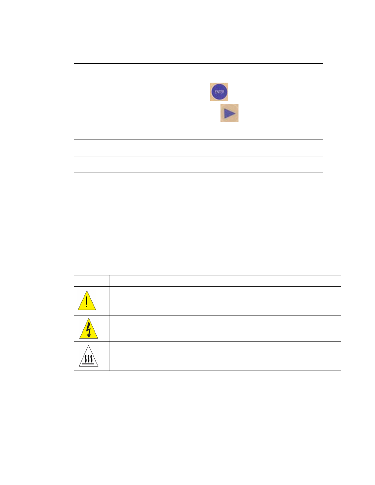
CAUTION: Risk of danger! This symbol identifies components that pose a risk of
personal injury or damage to the instrument if improperly handled. Wherever this
symbol appears, consult the manual for further information before proceeding
CAUTION: Risk of electrical shock! This symbol identifies components that pose a
risk of electrical shock if improperly handled
CAUTION: Hot surface! This symbol identifies components that pose a risk of
personal injury due to excessive heat if improperly handled
iv
Page 6
S1000 Thermal Cycler Manual
Instrument Safety Warnings
The following warning labels display on the instrument, and refer directly to the safe use of this
S1000 thermal cycler (Table 4).
Table 4. Instrument safety warning labels
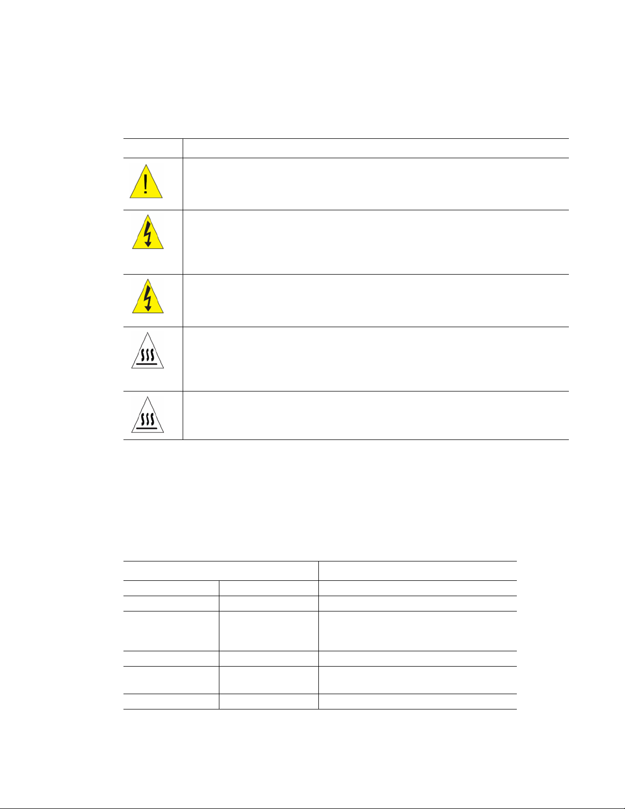
Icon Meaning
Warning about risk of harm to body or equipment.
Operating the S1000 thermal cycler before reading this manual can constitute a
personal injury hazard. Only qualified laboratory personnel should operate this
instrument
Warning about risk of harm to body or equipment from electrical shock.
Do not attempt to repair or remove the outer case of this thermal cycler base, power
supply, heat pump, or other accessories. If you open these instruments, you put
yourself at risk for electrical shock and void your warranty. All repairs must be done
by an authorized repair service
Never remove the outer case of a thermal cycler base. This may cause you to
receive an electrical shock.
This thermal cycler uses neutral fusing, which means that live power could still be
exposed inside the instrument even when the fuse is blown or removed
Warning about risk of burning.
A thermal cycler generates enough heat to cause serious burns. Wear safety
goggles or other eye protection at all times during operation. Always allow the
sample block to return to idle temperature before opening the lid and removing
samples. Always allow maximum clearance to avoid accidental skin burns
Warning about risk of explosion.
The sample blocks can become hot enough during the course of normal operation
to cause liquids to boil and explode
Safety and Regulatory Compliance
This instrument has been tested and found to be in compliance with all applicable
requirements of the following safety and electromagnetic standards (Table 5).
Table 5. Safe use specifications
Safe User Requirements Specifications
Input power Rated 100–240 Vac, 50–60 Hz
Fuses 250 V, 10 A
Temperature Indoor use Ambient temperature of 15–31°C. Relative
humidity maximum of 80%
(noncondensing)
Altitude Up to 2,000 meters above sea level
Overvoltage
Categories
Pollution degree 2
II
v
Page 7

Safety and Regulatory Compliance
SAFETY COMPLIANCE
This instrument has been tested and found to be in compliance with all applicable
requirements of the following safety and electromagnetic standards:
• UL Std No. 61010A-1 Electrical Equipment for Measurement, Control, and
Laboratory Use, Part 1: General Requirements
• UL Std No. 61010A-2-010 Electrical Equipment for Measurement, Control, and
Laboratory Use, Part 1: General Requirements
• CAN/CSA C22.2 No. 1010.1-92 - Safety Requirements for Electrical Equipment for
Measurement, Control, and Laboratory Use, Part 1: General Requirements
(includes Amendment 1)
• CAN/CSA C22.2 No. 1010.1B-97 - Amendment 2 CAN/CSA C22.2 No. 1010.1-92
- Safety Requirements for Electrical Equipment for Measurement, Control, and
Laboratory Use, Part 1: General Requirements
• CAN/CSA C22.2 No. 1010.2.010A-97 - Safety Requirements for Electrical
Equipment for Measurement, Control, and Laboratory Use, Part 2-010: Particular
Requirements for Laboratory Equipment for the Heating of Materials, Amendment
No. 1
• IEC 61010-1 Safety Requirements for Electrical Equipment for Measurement,
Control, and Laboratory Use, Part 1: General Requirements
• IEC 61010-1 Safety Requirements for Electrical Equipment for Measurement,
Control, and Laboratory use, Part 2: Particular Requirements for Laboratory
Equipment for the Heating of Materials
ELECTROMAGNETIC COMPATIBILITY (EMC)
• FCC Title 47 Part 15B as a Class A digital device
• EN61326 Class A Electrical Equipment for measurement, control, and laboratory use
- EMC Requirements
FCC WARNINGS AND NOTES
•Warning. Changes or modifications to this unit, not expressly approved by the party
responsible for compliance, could void the user’s authority to operate the equipment
•Note. This equipment has been tested and found to comply with the limits for a Class A
digital device, pursuant to part 15 of the FCC Rules. These limits are designed to provide
reasonable protection against harmful interference when the equipment is operated in a
commercial environment. This equipment generates, uses, and can radiate radio
frequency energy and, if not installed and used in accordance with the instruction
manual, may cause harmful interference to radio communications. Operation of this
equipment in a residential area is likely to cause harmful interference in which case the
user will be required to correct the interference, at his own expense
• Note regarding FCC compliance. Although this design of instrument has been tested
and found to comply with Part 15, Subpart B of the FCC Rules for a Class A digital
device, please note that this compliance is voluntary, for the instrument qualifies as an
“exempted device” under 47 CFR 15.103(c), in regard to the cited FCC regulations in
effect at the time of manufacture
• Note regarding Canadian EMC compliance: Le present appareil numerique n’emet
pas de bruits radioelectrique depassant les limites applicables aux appareils numeriques
de class A prescrites dans le reglement sur le brouillage radioelectrique edicte par le
Ministere des Communications du Canada
•Cables. Shielded cables must be used with this unit to ensure compliance with the Class
A FCC limits
• Use only Bio-Rad USB cable (catalog #184-8000) when using any 1000-series cycler
vi
Page 8

Table of Contents
Bio-Rad Laboratories Resources . . . . . . . . . . . . . . . . . . . . . . . . . . . . . . . . . . . . . . iii
Warranty . . . . . . . . . . . . . . . . . . . . . . . . . . . . . . . . . . . . . . . . . . . . . . . . . . . . . . . . . iii
Writing Conventions Used In This Manual. . . . . . . . . . . . . . . . . . . . . . . . . . . . . . . . iii
Safety and Regulatory Compliance . . . . . . . . . . . . . . . . . . . . . . . . . . . . . . . . . . . . . iv
S1000 Thermal Cycler Manual
Chapter 1. Introduction to the S1000™ Thermal Cycler . . . . . . . . . . . . . . . 1
System Overview . . . . . . . . . . . . . . . . . . . . . . . . . . . . . . . . . . . . . . . . . . . . . . . . . . . 1
Reaction Modules . . . . . . . . . . . . . . . . . . . . . . . . . . . . . . . . . . . . . . . . . . . . . . . . . . 3
Setting Up the S1000 Thermal Cycler . . . . . . . . . . . . . . . . . . . . . . . . . . . . . . . . . . . 5
Operating the Reaction Module Lid . . . . . . . . . . . . . . . . . . . . . . . . . . . . . . . . . . . . . 7
Chapter 2. Creating and Editing Protocols . . . . . . . . . . . . . . . . . . . . . . . . 11
Protocol Steps . . . . . . . . . . . . . . . . . . . . . . . . . . . . . . . . . . . . . . . . . . . . . . . . . . . . 11
Creating a New Protocol . . . . . . . . . . . . . . . . . . . . . . . . . . . . . . . . . . . . . . . . . . . . 12
Parameters for Temperature or Gradient Steps . . . . . . . . . . . . . . . . . . . . . . . . . . 19
Editing an Existing Protocol. . . . . . . . . . . . . . . . . . . . . . . . . . . . . . . . . . . . . . . . . . 22
Sample Volume and Lid Temperature . . . . . . . . . . . . . . . . . . . . . . . . . . . . . . . . . . 27
Chapter 3. Running Protocols . . . . . . . . . . . . . . . . . . . . . . . . . . . . . . . . . . . 29
Preparing to Run a Protocol . . . . . . . . . . . . . . . . . . . . . . . . . . . . . . . . . . . . . . . . . 29
Monitoring the Protocol Run . . . . . . . . . . . . . . . . . . . . . . . . . . . . . . . . . . . . . . . . . 32
Pausing and Resuming a Run . . . . . . . . . . . . . . . . . . . . . . . . . . . . . . . . . . . . . . . . 33
Skipping a Step During the Run . . . . . . . . . . . . . . . . . . . . . . . . . . . . . . . . . . . . . . 34
Canceling a Run. . . . . . . . . . . . . . . . . . . . . . . . . . . . . . . . . . . . . . . . . . . . . . . . . . . 34
Incubating Samples . . . . . . . . . . . . . . . . . . . . . . . . . . . . . . . . . . . . . . . . . . . . . . . . 35
Chapter 4. Managing Protocol Files and Folders . . . . . . . . . . . . . . . . . . . 39
Managing Protocol Files and Folders . . . . . . . . . . . . . . . . . . . . . . . . . . . . . . . . . . 39
vii
Page 9

Chapter 5. Optimizing PCR on the S1000 Thermal Cycler . . . . . . . . . . . . 47
Optimizing a Protocol for Faster PCR . . . . . . . . . . . . . . . . . . . . . . . . . . . . . . . . . . 47
Optimizing Annealing Temperature Steps with a Gradient . . . . . . . . . . . . . . . . . . 49
Optimizing PCR With Small Sample Volumes . . . . . . . . . . . . . . . . . . . . . . . . . . . . 50
Transferring Protocols from Another Thermal Cycler . . . . . . . . . . . . . . . . . . . . . . 50
Troubleshooting PCR Problems . . . . . . . . . . . . . . . . . . . . . . . . . . . . . . . . . . . . . . 50
Selecting Compatible Reaction Vessels and Sealing Options . . . . . . . . . . . . . . . 51
Chapter 6. Advanced Tools and Functions . . . . . . . . . . . . . . . . . . . . . . . . 53
TOOLS Options . . . . . . . . . . . . . . . . . . . . . . . . . . . . . . . . . . . . . . . . . . . . . . . . . . . 53
Controlling S1000 Thermal Cyclers with a C1000 Thermal Cycler . . . . . . . . . . . . 61
Chapter 7. Maintenance and Troubleshooting . . . . . . . . . . . . . . . . . . . . . 63
Cleaning and Maintaining the S1000 Thermal Cycler . . . . . . . . . . . . . . . . . . . . . . 63
Maintaining Sufficient Air Flow . . . . . . . . . . . . . . . . . . . . . . . . . . . . . . . . . . . . . . . 65
Troubleshooting Error Messages on the S1000 Cycler . . . . . . . . . . . . . . . . . . . . . 66
Appendix A: Preinstalled Protocols . . . . . . . . . . . . . . . . . . . . . . . . . . . . . . . 71
Standard Protocols . . . . . . . . . . . . . . . . . . . . . . . . . . . . . . . . . . . . . . . . . . . . . . . . 71
Touchdown Protocol . . . . . . . . . . . . . . . . . . . . . . . . . . . . . . . . . . . . . . . . . . . . . . . 72
Optimized Protocol Using iTaq™ Polymerase . . . . . . . . . . . . . . . . . . . . . . . . . . . 72
Optimized Protocols Using iProof™ Polymerase . . . . . . . . . . . . . . . . . . . . . . . . . 73
Optimized Protocol Using the iScript™ Reverse Transcriptase . . . . . . . . . . . . . . 74
Nested Primer Protocols . . . . . . . . . . . . . . . . . . . . . . . . . . . . . . . . . . . . . . . . . . . . 74
Appendix B: Ordering Information . . . . . . . . . . . . . . . . . . . . . . . . . . . . . . . . 77
Components of Bio-Rad’s 1000-Series Thermal Cyclers . . . . . . . . . . . . . . . . . . . 77
Accessories for the 1000-Series Thermal Cyclers. . . . . . . . . . . . . . . . . . . . . . . . . 78
Index . . . . . . . . . . . . . . . . . . . . . . . . . . . . . . . . . . . . . . . . . . . . . . . . . . . . . . . . 81
viii
Page 10
S1000 Thermal Cycler Manual
1 Introduction to the S1000™
Thermal Cycler
Read this chapter for information on setting up the S1000 thermal cycler.
• System overview (below)
• Reaction modules (page 3)
• Setting up the S1000 thermal cycler (page 5)
• Operating the reaction module lid (page 7)
System Overview
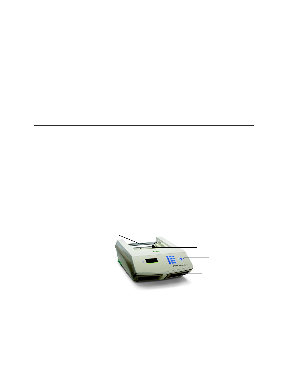
The S1000 thermal cycler base (Figure 1) includes:
• Reaction module bay – holds the inserted reaction module
• Reaction module locking bar – locks the inserted module in place
• Control panel – provides access to all the functions needed to create and run PCR
protocols
• Air vents – allow the thermal cycler to heat and cool quickly
Module locking bar
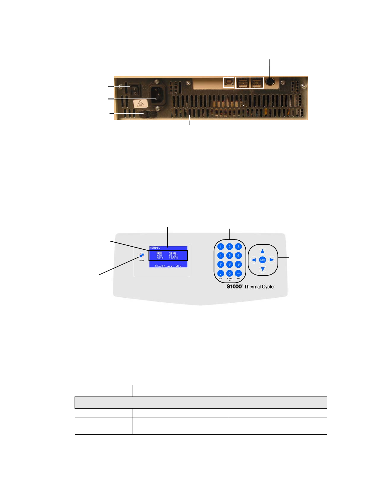
The back panel of the S1000 thermal cycler includes data ports (Figure 2).
• USB B port — connects the S1000 thermal cycler to a C1000™ thermal cycler
• USB A ports — currently inactive
Reaction module bay
Control panel
Air vents
Figure 1. Frontal view of the S1000 thermal cycler.
1
Page 11
System Overview
• Test port — for service testing only
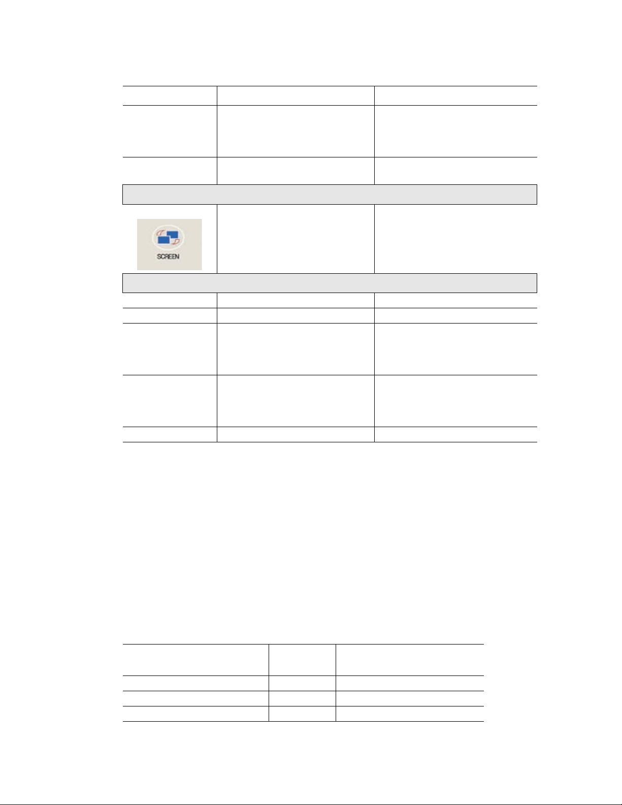
The control panel on the S1000 thermal cycler provides access to all the functions needed to
run the thermal cycler and includes the following components:
• Liquid crystal display (LCD) — displays the main menu and other screens
• Command, numeric, and navigation keys — use these keys to enter commands,
The main screen is displayed after booting is complete. Figure 3 shows the components of the
control panel.
USB B port
Power
switch
Power
input
Fuses
Cooling vents
Figure 2. Back panel of the S1000 thermal cycler.
numbers, or letters, and navigate various screens
Numeric and
LCD
command keys
Test port
USB A ports
Main menu
options
Navigation
keys
Screen
key
Figure 3. Components of the control panel on the S1000 thermal cycler.
Function of the Control Panel Keys
The control panel of the S1000 thermal cycler contains five sets of keys with the functions
listed in Table 6.
Table 6. Function of keys on control panel
Key Function Additional Notes
Numeric and Command Keys
1 through 9 Enter numbers
0, INCUBATE Inserts a zero or infinity, or starts
instant incubation
2
Page 12
S1000 Thermal Cycler Manual
Table 6. Function of keys on control panel (continued)
Key Function Additional Notes
CANCEL (–) Enters a minus sign or cancels a
function
PAUSE (
SCREEN key
Navigation Keys
Right arrow Moves the cursor to the right
Left arrow Moves the cursor to the left
Up arrow Moves the cursor up Press the up arrow key to scroll
Down arrow Moves the cursor down Press the down arrow key to scroll
ENTER Confirms a selection
.
) Enters a decimal point or pauses
a protocol
Toggles between screens for
alternative views
Press this key to delete an entry,
cancel a function, stop a protocol,
end an incubation, or delete text
on the screen
Press this key to view the status of
a run
from A to Z on the screen. For
example, press the up key three
times to select the letter C
from Z to A on the screen. For
example, press the down key eight
times to select the letter S
Reaction Modules
The S1000 thermal cycler is compatible with any 1000-series reaction module. The reaction
modules come in three block sizes: the 96-, dual 48-, or 384-well block. Each block in the
reaction module includes a fully adjustable heated lid that is capable of running reliably with a
broad range of reaction vessels.
Recommended Sample Volume
When using the S1000 thermal cycler, the maximum sample volume is determined by the type
of reaction module used. -well reaction module is used. Table 7 lists the recommended
sample volume, as well as the maximum sample volume to be used with different reaction
modules.
Table 7. Size and volume limit for the 1000-series reaction modules
Number of Wells
Dual 48/48 2 10–50 µl (50 µl limit)
96 1 10–50 µl (50 µl limit)
384 1 3–30 µl (30 µl limit)
Number of
Blocks
Recommended Sample
Volume (Upper Limit)
3
Page 13

Reaction Modules
Specifications of Reaction Modules
Specifications for each 1000-series reaction module are listed in Table 8.
Table 8. Reaction module specifications
Feature 96-Well Fast Dual 48/48 Fast 384-Well
Sample capacity 96 x 0.2 ml tubes 2 x 48 x 0.2 ml tubes 1 x 384-well PCR
Gradient direction Back (upper
Gradient temperature
range
Gradient temperature
differential
Gradient accuracy ±0.2°C of
Gradient (end row)
uniformity
Gradient calculator
accuracy
Heated lid temperature 0–110°C 0–110°C 0–110°C
Average ramp rate 3.3°C/sec 3.0°C/sec 2.0°C/sec
Maximum ramp rate 5.0°C 4.0°C 2.5°C
Temperature range 0–100°C 0–100°C 0–100°C
Temperature accuracy ±0.2°C of
Temperature uniformity ±0.4°C well-to-well
microplate
Back (upper
temperature) to front
(lower temperature)
of block
30–100°C 30–100°C 30–100°C
1–24°C 1–24°C 1–24°C
programmed
temperature at end
rows
±0.4°C well-to-well
(within row) within 10
sec of arrival at
target temperature
±0.4°C of the actual
well temperature
programmed target
at 90°C
within 10 sec of
arrival at 90°C
temperature) to front
(lower temperature)
of block
±0.2°C of
programmed
temperature at end
rows
±0.4°C well-to-well
(within row) within 10
sec of arrival at
target temperature
±0.4°C of the actual
well temperature
±0.2°C of
programmed target
at 90°C
±0.4°C well-to-well
within 10 sec of
arrival at 90°C
Back (upper
temperature) to front
(lower temperature)
of block
±0.2°C of
programmed
temperature at end
rows
±0.4°C well-to-well
(within row) within 10
sec of arrival at
target temperature
±0.4°C of the actual
well temperature
±0.2°C of
programmed target
at 90°C
±0.4°C well-to-well
within 10 sec of
arrival at 90°C
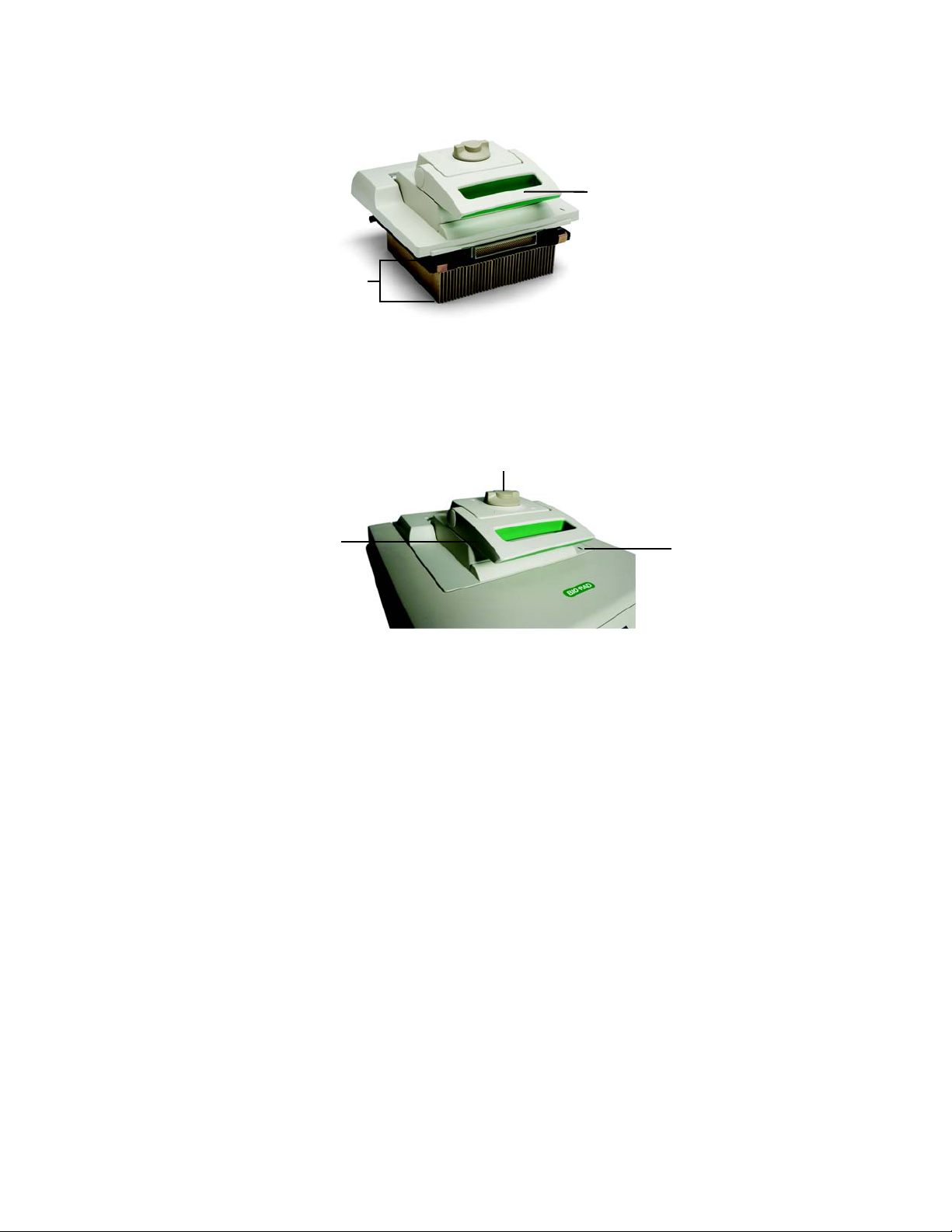
Each reaction module contains cooling fins for fast heating and cooling and a fully adjustable,
heated lid. Figure 4 shows the lid and cooling fins for the 96-well reaction module.
• Heated inner lid — adjusts the lid temperature to prevent condensation and
evaporation
• Sample/reaction block — holds reaction vessels, including tubes and microplates
4
Page 14
S1000 Thermal Cycler Manual
Lid
Cooling fins
Figure 4. The lid and cooling fins of a 96-well reaction module.
The top of a reaction module lid includes a lid lever, lid force knob, and status LED (Figure 5).
• Lid lever — opens and closes the lid
• Lid force knob — sets lid force and seals the reaction
• Status LED — turns on to indicate that the block is selected or running
Lid force knob
Lid lever
Figure 5. A top view of a reaction module.
Setting Up the S1000 Thermal Cycler
The S1000 thermal cycler package includes:
• S1000 thermal cycler base
• Power cord
• Consumables selection guide
• Instruction manual
• Quick guide for system installation
Reaction modules for use with the S1000 thermal cycler are shipped in separate packaging.
Remove all packaging materials and store them for future use. If any item is missing or
damaged, contact your local Bio-Rad office.
Place the S1000 thermal cycler base on a flat, dry surface with sufficient cool airflow to run
properly. The instrument can run in two modes: stand-alone or software-controlled. When
running the system under software-controlled mode, make sure there is sufficient space for a
computer during setup.
Status
LED
5
Page 15
Setting Up the S1000 Thermal Cycler
To insert either a 96-, dual 48-, or 384-well reaction module into the reaction module bay
of the thermal cycler base, follow these instructions:
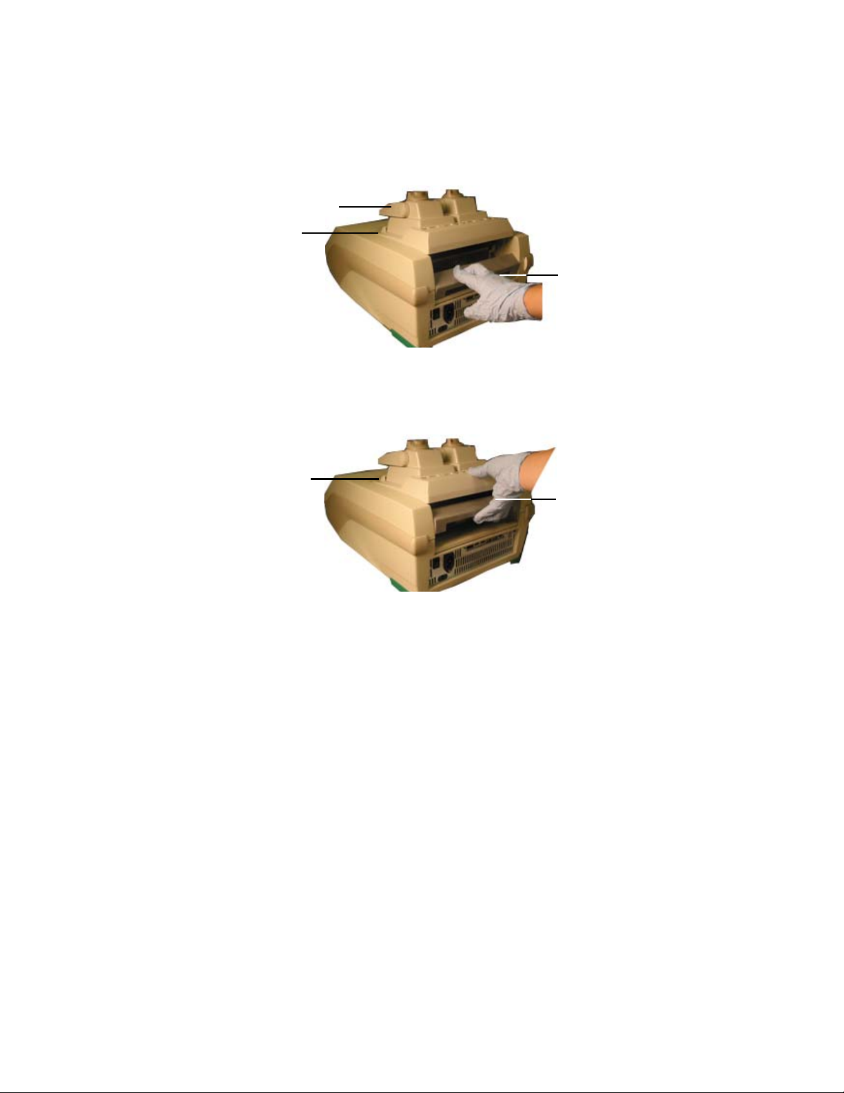
1. With the locking bar in the down position and the lid lever of the reaction module
pointing to the front, lift the reaction module into the reaction module bay (Figure 6).
Leave about 1–2 cm of space in front of the module.
Lid lever (front)
Leave space here
Figure 6. Inserting the reaction module into the bay.
2. Pull the locking bar up to lock the reaction module in place (Figure 7). There is no space
at the front of the module when it is locked into the S1000 thermal cycler base.
TIP: Store the reaction module in the base when it is not in use.
Locking bar
(down position
when unlocked)
No space here
(in the locked position)
Figure 7. Locking the reaction module in place.
3. Plug the supplied power cord into the appropriate electrical outlet.
4. Turn on the thermal cycler using the power switch on the back panel of the thermal
cycler base.
NOTE: Before operating the thermal cycler, be sure to read the safety
specifications (“Safety and Regulatory Compliance” on page iv) and operating
requirements.
5. When the S1000 thermal cycler starts up, it goes through two screens: the black booting
and the self-test screens. Once the self-test is run to verify proper functions, the main
menu is displayed. Use the main menu to begin operating the thermal cycler.
To remove the reaction module from the thermal cycler base, follow these instructions:
1. Turn off the thermal cycler.
2. Unlock and release the reaction module by pushing the locking bar down.
Locking bar
(up position
when locked)
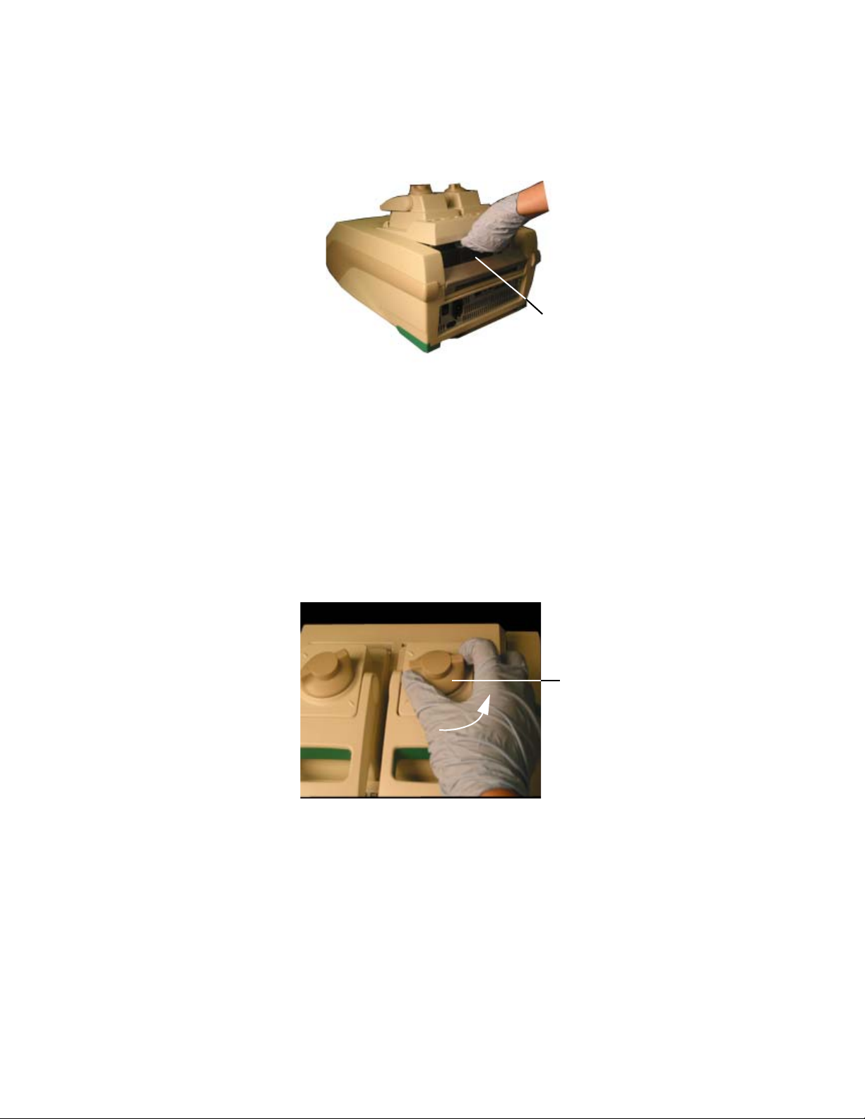
3. Carefully lift the reaction module out of the bay (Figure 8).
WARNING! Cooling fins may be hot immediately after running a protocol or
incubation. Before lifting the reaction module, make sure that the cooling fins are
not hot.
6
Page 16
4. After removing the reaction module from the S1000 thermal cycler, store it on a clean,
flat surface where it cannot get bumped, scraped, or dropped.
Scraping the cooling fins of the reaction module or dropping the module on the fins
could compromise the ability of the module to heat and cool correctly.
Figure 8. Lifting the reaction module out of the bay.
Operating the Reaction Module Lid
S1000 Thermal Cycler Manual
Cooling fins
The inner lid of the reaction module applies heat and force to the reaction vessel lids (caps or
tape) to produce consistent and successful reactions. Heating the inner lid prevents
condensation, while applying force seals the reaction to prevent evaporation.
WARNING! After a run, the heated inner lid can remain hot. Use caution when
opening and closing the lid.
To open the lid, use the following steps:
1. Turn the lid force knob counterclockwise to release the inner lid (Figure 9).
Lid force knob
(Turn counterclockwise
to release the lid)
Figure 9. Turn the lid force knob counterclockwise to release the inner lid.
7
Page 17
Operating the Reaction Module Lid
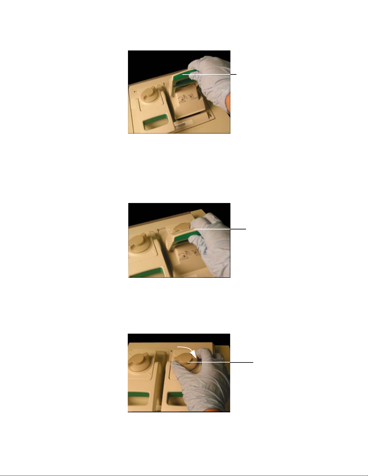
2. To open the lid, push the lid lever back and then lift it up (Figure 10).
3. Lift the lid lever completely until the reaction module stays open without assistance.
To close the lid, use the following steps:
1. Push the lid lever down (Figure 11), making sure that the front of the lid is secured
beneath the housing, and then lock it in place.
Lid lever
Figure 10. Lift the lid lever up to open the lid.
Lid lever
Figure 11. Push the lid lever down.
2. Adjust the lid force by turning the lid force knob (Figure 12).
• Turn the knob 1/4 clockwise (to the right) to increase the lid force
• Turn the knob 1/4 counterclockwise (to the left) to decrease the lid force
Adjust the lid force to a similar setting each time by turning it to the same position.
NOTE: The position marks on the lid indicate 1/4 turns.
Lid force knob
(Turn clockwise to
secure the lid)
Figure 12. Adjust the lid force by turning the lid lever.
8
Page 18
S1000 Thermal Cycler Manual
Loading Sample Vessels into the Reaction Block
To ensure uniform heating and cooling of samples, vessels must be in complete contact with
the reaction block. Adequate contact is achieved by:
• Confirming that the block is clean before loading samples
• Firmly pressing the individual tubes or the microplate into the block wells
TIP: When using one or a few tubes, make sure to place them in the center of the
block to ensure uniform thermal cycling of all samples. Use the tube frame (catalog
#184-9000), or load at least one empty tube in each corner of the block to ensure
that the lid exerts even pressure on individual tubes.
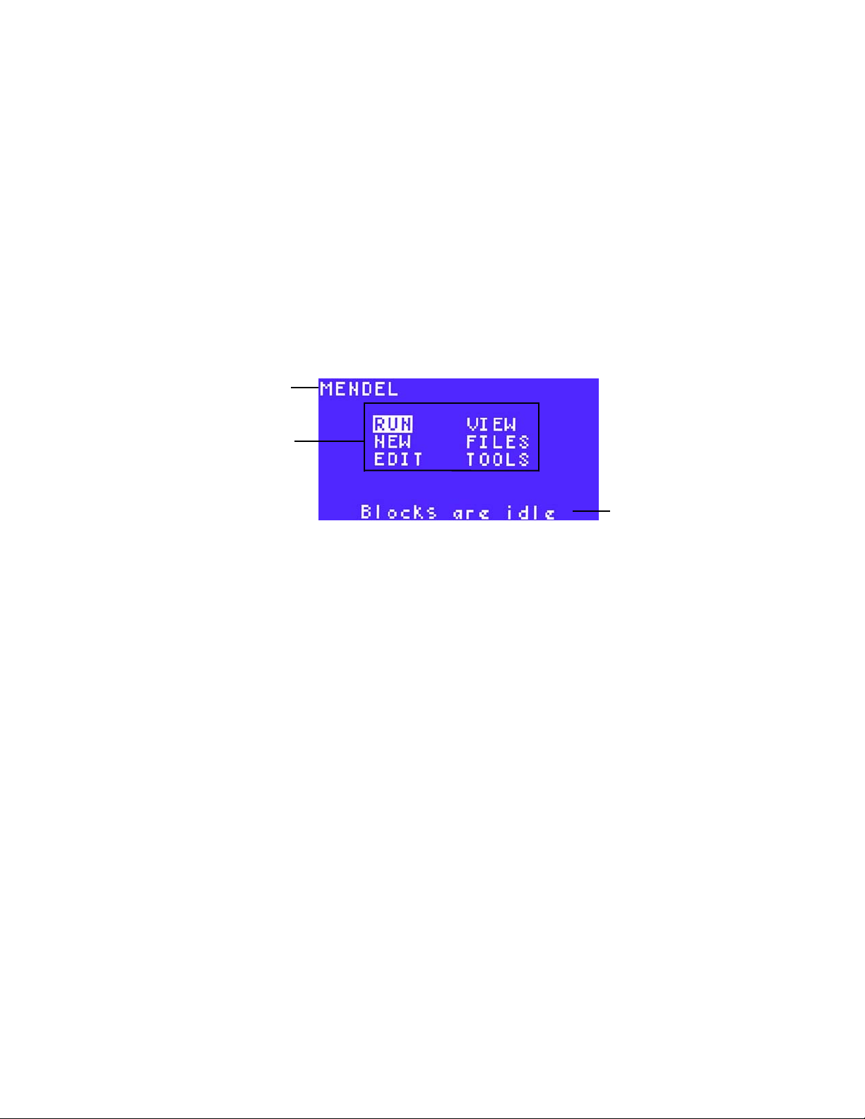
Main Menu
The main menu (Figure 13) provides access to all thermal cycler operations and displays the
status of the reaction module and the name of the thermal cycler.
Name of
thermal cycler
Options
Status message
Figure 13. The main window of the S1000 thermal cycler.
Select the options in the main menu to start these instrument functions:
• RUN
• NEW
• EDIT — to modify stored protocol files
• FILES
• VIEW
• TOOLS
— to run an existing protocol file
— to create a new protocol file
— to copy, move, rename, delete, or secure protocol files and/or folders
— to review an existing protocol file
— to change thermal cycler settings or to view the last protocol that was run
The File Tree
All protocol files are stored in the file tree. The file tree displays when you need to select a
protocol to run, edit, or view.
The file tree (Figure 14) includes these folders:
• MAIN folder — stores the preinstalled protocols and cannot be deleted or renamed.
The preinstalled files can be run or copied by any user. Do not store user-created
protocols in the MAIN folder
9
Page 19

Operating the Reaction Module Lid
• User folders — contain user-created protocol files. User folders and associated files
can be secured with a password. The files cannot be edited or deleted without using
the password
Selected folder
User folders
Selected file
Figure 14. The file tree of the S1000 thermal cycler.
NOTE: If a folder contains more than six protocols, use the arrow keys to scroll
down to see all the protocols. All folder names are displayed with angle brackets (<
and >) surrounding the name.
User-created
protocol file
Preinstalled
protocols
10
Page 20

S1000 Thermal Cycler Manual
2 Creating and Editing Protocols
Read this chapter for information on creating and editing protocols.
• Protocol steps (below)
• Creating a new protocol (page 12)
• Parameters for temperature or gradient steps (page 19)
• Editing an existing protocol (page 22)
• Sample volume and lid temperature (page 27)
Protocol Steps
Table 9 includes a list of steps in a protocol. The table also includes the limits and range of the
parameters.
Table 9. Protocol steps and parameters of the S1000 thermal cycler
Step Name Parameters and Ranges Description
TEMP
(Temperature)
Temperature in °C: The target
temperature between 0.0 and
100.0°C in tenths of a degree
Hold time: The hold time
between 1 sec and 18 hr in the
format of hr:min:sec. To enter an
infinite hold, press the ∝ (infinite,
0) key
Instructs the thermal cycler to ramp to
the target temperature, and hold that
temperature for the specified amount
of time
11
Page 21

Creating a New Protocol
Table 9. Protocol steps and parameters of the S1000 thermal cycler (continued)
Step Name Parameters and Ranges Description
GRAD
(Gradient
range)
GOTO GOTO step: The step number of
END (No parameters) A protocol step that instructs the
Lower: The lower temperature
in the gradient. Enter a number
between 30.0 and 99.0°C in
tenths of a degree
Upper: The upper temperature
in the gradient. The maximum
temperature is 100°C. Enter a
temperature within 24.0°C of the
lower temperature
Time:The hold time between 1
sec and 18 hr in the format of
hr:min:sec. To enter an infinite
hold, press the ∝ key (infinite, 0)
key
the first step in the repeat.
ADDTNL REPEATS: The
number of additional times that
the steps repeat.
Instructs the thermal cycler to ramp to
the target temperature gradient across
the block, and hold that temperature
gradient for the specified amount of
time
A protocol step that instructs the
thermal cycler to repeat a set of steps
for the specified number of times.
NOTE: The total number of cycles in
the protocol is the number of GOTO
repeats, plus the first cycle.
thermal cycler to finish the protocol
Creating a New Protocol
NOTE: The internal memory of the S1000 thermal cycler can hold up to 400, 2-step
protocols.
To create a protocol:
1. Select NEW from the main menu (Figure 15). Press ENTER to confirm the selection.
Figure 15. Select NEW from the main menu.
2. Use the numeric keys to enter the name of the new protocol file. Enter a letter by
pressing the up or down arrow key and a number by pressing the numbered key. For
example, to select the letter C, press the up key 3 times. To select the letter S, press the
12
Page 22
S1000 Thermal Cycler Manual
down key eight times. Press ENTER to continue to the next space. Press ENTER to
continue to the next screen.
NOTE: A protocol file name can contain 1–8 characters and must be unique to the
folder. To delete or change a letter, press CANCEL and select a new letter. To
delete the entire name, press CANCEL multiple times.
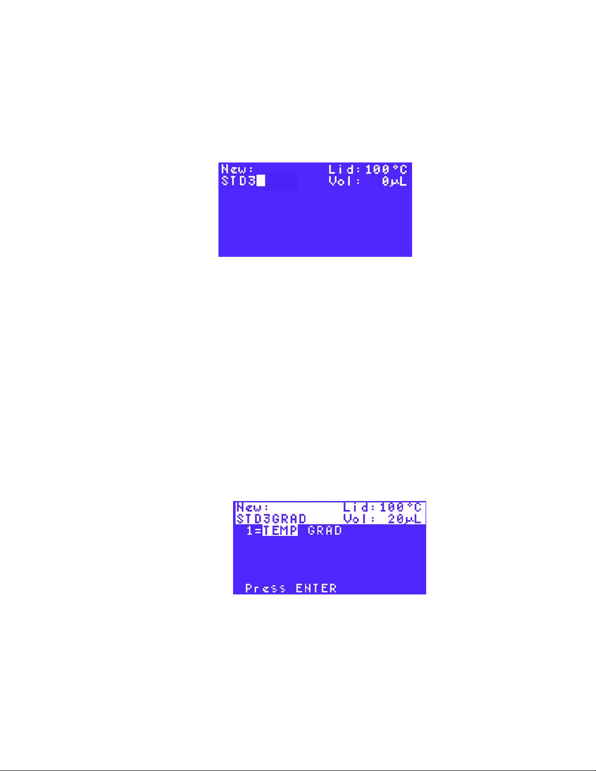
In Figure 16, the characters STD3 are entered, and the cursor is highlighting the next
space.
Figure 16. STD3 is entered as the protocol name.
3. (Optional) Enter a new lid temperature, and press ENTER to continue to the next screen.
NOTE: The lid temperature can range from 0 to 110°C. When the block is running
an infinite hold at a temperature below the Turn off below parameter, the lid heater
maintains 31.0°C. To change the default Turn off below parameter, select TOOLS
> DEFAULTS.
4. (Optional) Enter the sample volume in microliters (µl), and press ENTER to continue to
the next screen.
NOTE: Entering a sample volume between 1 and 50 selects Calculated
Temperature control mode, which is the standard mode. Entering zero (0) in the
volume field selects Block mode. Calculated mode is the recommended mode
because it most accurately represents the actual sample temperature. For more
information about Temperature control modes, see page 27.
5. Using the arrow keys, select TEMP to enter a temperature step or GRAD to enter a
gradient temperature step in the protocol file. Press ENTER to continue to the next
screen.
In Figure 17, TEMP is selected as the temperature step.
Figure 17. TEMP is selected as the temperature step in this protocol file.
NOTE: The first step in a protocol must be either a TEMP or GRAD step.
6. Enter the target temperature between 0 (zero) and 100.0°C for the temperature step.
Press ENTER to continue to enter the next item in the protocol.
13
Page 23
Creating a New Protocol
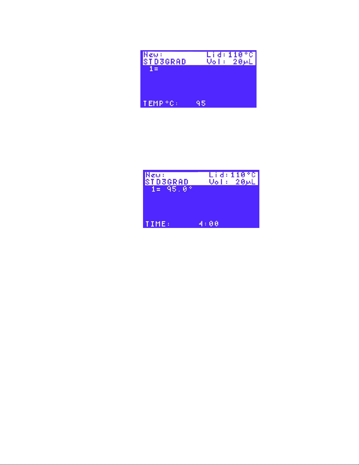
In Figure 18, the target temperature is 95°C.
7. Enter the hold time (TIME) in minutes and seconds using the numeric keys. The hold
time (TIME) ranges between 0:01 (one second) and 18:00:00 (18 hours). Entering 0 (zero)
adds an infinite hold and holds this step FOREVER. Press ENTER to continue to the
next field.
For example, to enter 4 minutes (4:00), type 400. To enter 30 seconds, type 30. In
Figure 19, the hold time is four minutes.
Figure 18. Target temperature of 95°C is used in this protocol.
Figure 19. The hold time is 4 minutes in this protocol.
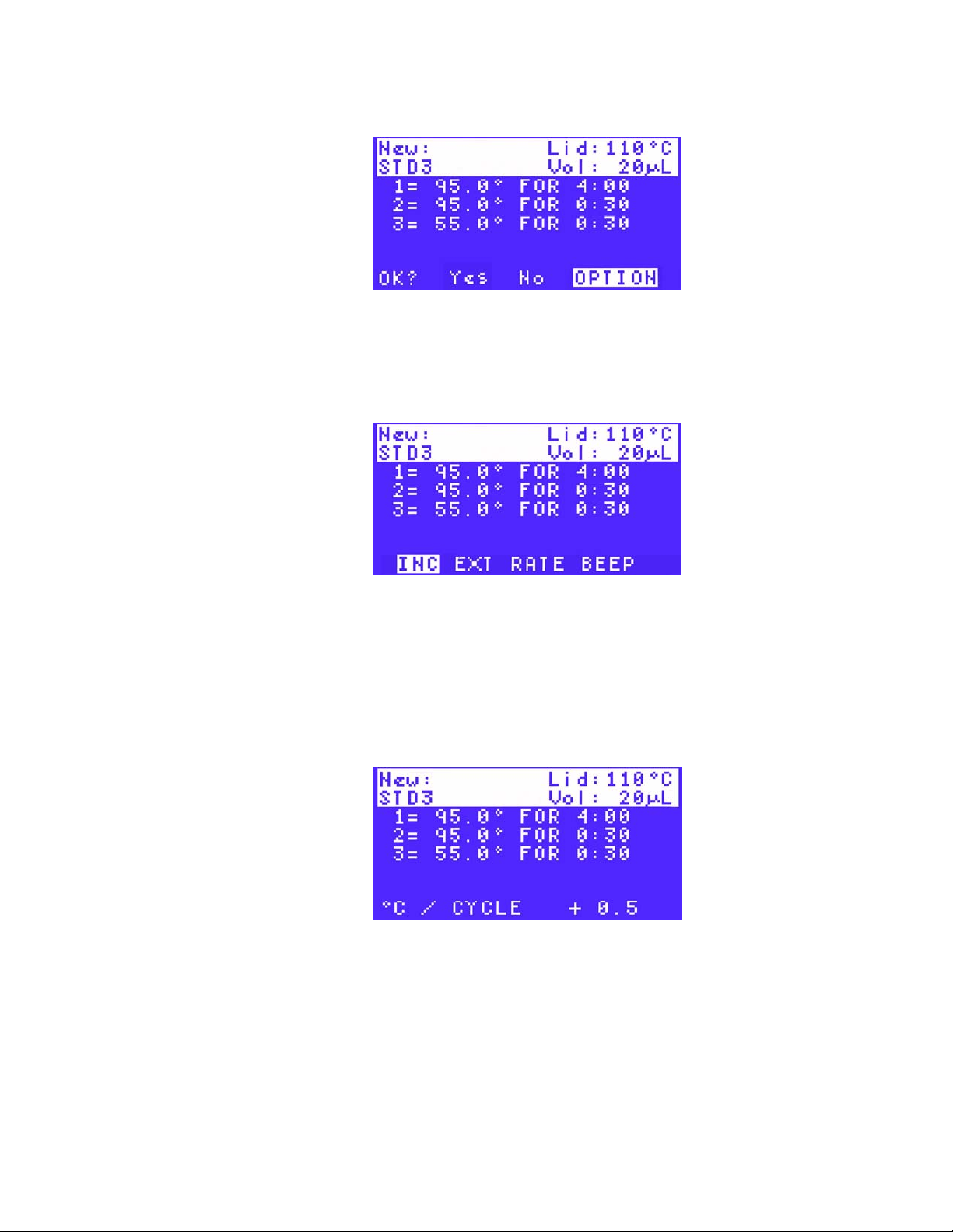
8. Select YES, No, or Option by pressing the right and left arrow keys. Press ENTER to
continue to the next screen.
• YES — to confirm the current parameters for this protocol step
• No — to change a parameter in this protocol step
• Option — to add more parameters to this protocol step. For more information
about entering options, see “Adding an Increment to a Temperature Step”
(page 19)
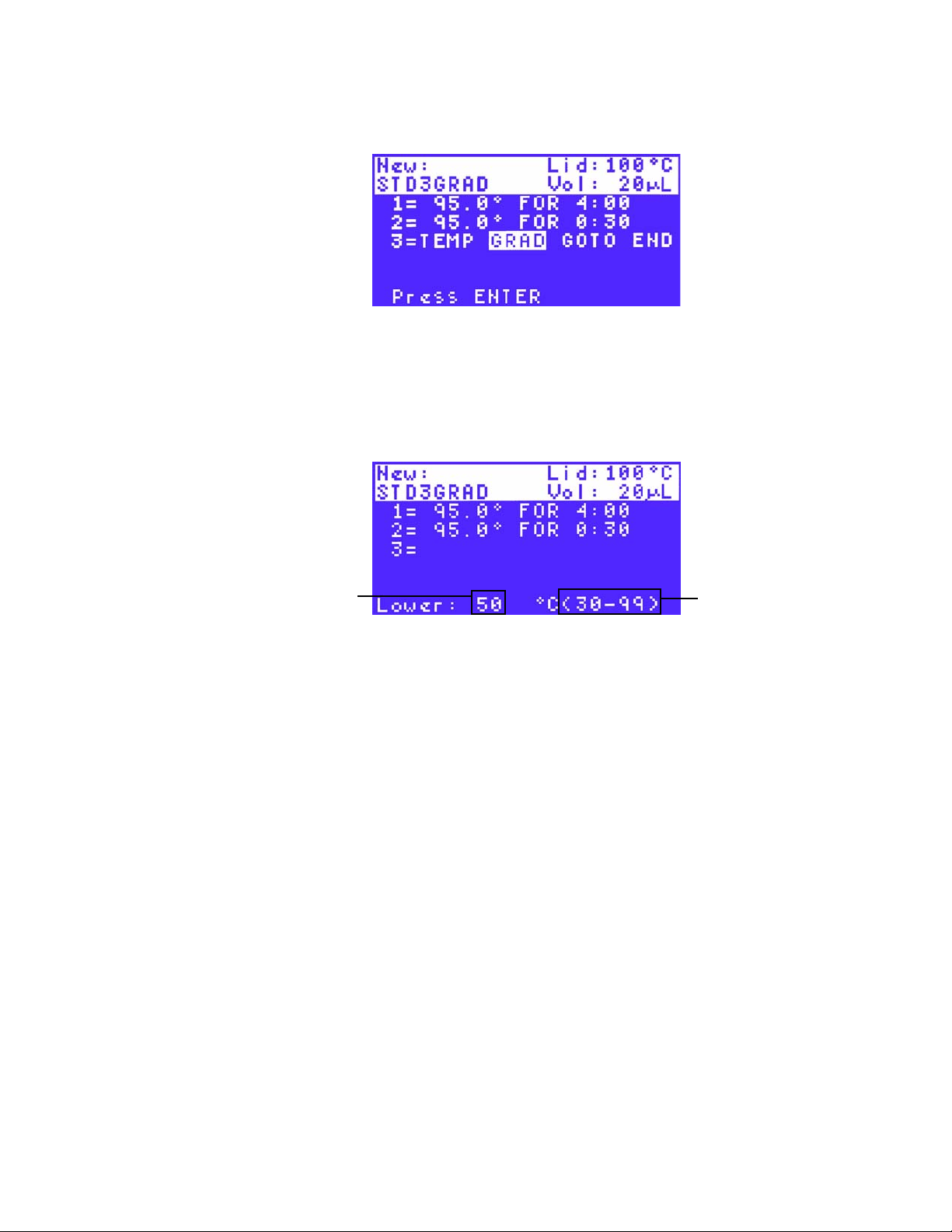
9. (Optional) Enter a gradient temperature step by pressing the right arrow key to select
GRAD (Figure 20). Press ENTER to continue to the next screen.
NOTE: A temperature gradient is limited to a 24°C spread. The lowest possible
“lower” temperature in the gradient is 30°C and the highest “upper” temperature is
14
Page 24
S1000 Thermal Cycler Manual
100°C. Therefore the lowest gradient is 30–54°C, and the highest possible gradient
is 76–100°C.
Figure 20. GRAD is selected in the gradient temperature step.
TIP: Check the temperature in each row of the block in a gradient by selecting the
gradient calculator tool (TOOLS > GRADCALC on page 58).
10.Enter the lower temperature in the gradient. The lower temperature is at the front (row H)
of the block.
In Figure 21, the lower temperature is 50°C.
Lower
temperature
(back row)
Figure 21. The lower temperature is 50°C in this protocol.
11.Enter the upper temperature in the gradient. The upper temperature is at the back (row
A) of the block.
NOTE: The range of temperature is limited by the widest available range for
gradient, which is 24°C. The highest value that can be entered for the upper
temperature is 100°C.
12.Enter a hold time between 0:01 (one second) and 18:00:00 (18 hours).
13.Select YES, No, or Option by pressing the right and left arrow keys, then press ENTER
to continue to the next screen:
• YES — to confirm the current parameters for this protocol step
• No — to change a parameter in this protocol step
• Option — to preview the temperature gradient. If Option is selected, select VIEW
on the next screen to view the gradient or EXT to add a hold time extension. Press
ENTER again to return to the previous screen
Range of
temperatures to
be chosen
15
Page 25
Creating a New Protocol
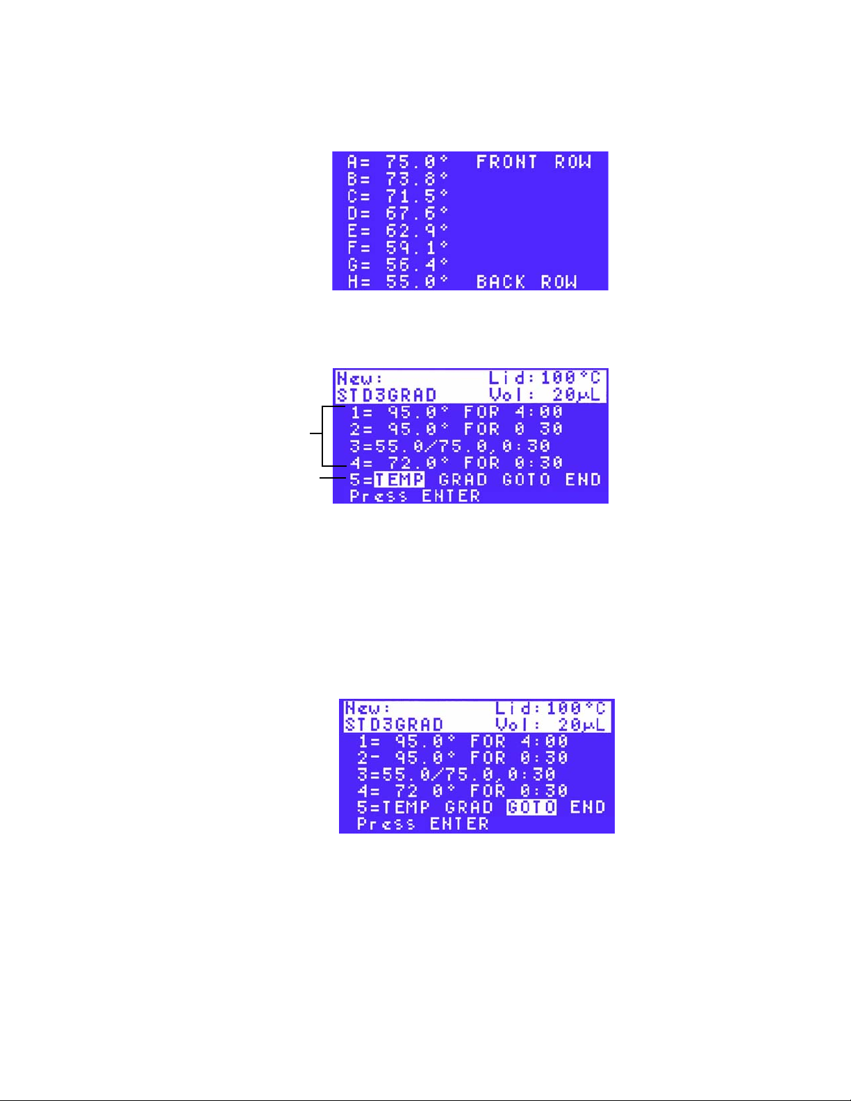
In Figure 22, the gradient is formed on a 96-well block with a range from 55–75°C. This
screen displays the approximate temperature of each row of the block, and labels the
front and back rows.
14.Repeat the instructions in steps 6–9 to continue entering additional temperature steps. In
Figure 23, four steps are entered.
Entered steps
Figure 22. The approximate temperature of each row of the block.
Choose new
step type
Figure 23. Enter all the temperature steps.
NOTE: A protocol can contain up to 99 protocol steps. The first step must be a
temperature (TEMP) step, while the last step must be an END step.
15.(Optional) To enter a GOTO step immediately after the set of steps to be repeated in a
cycle, use the arrow keys and select GOTO. Press ENTER to continue to the next
screen.
For more information about how the GOTO step creates a cycle, see “Protocol Steps”
(page 11).
In Figure 24, step 5 is a GOTO step.
Figure 24. A GOTO step is selected.
NOTE: The GOTO step cannot be the first or the last step in the protocol.
16
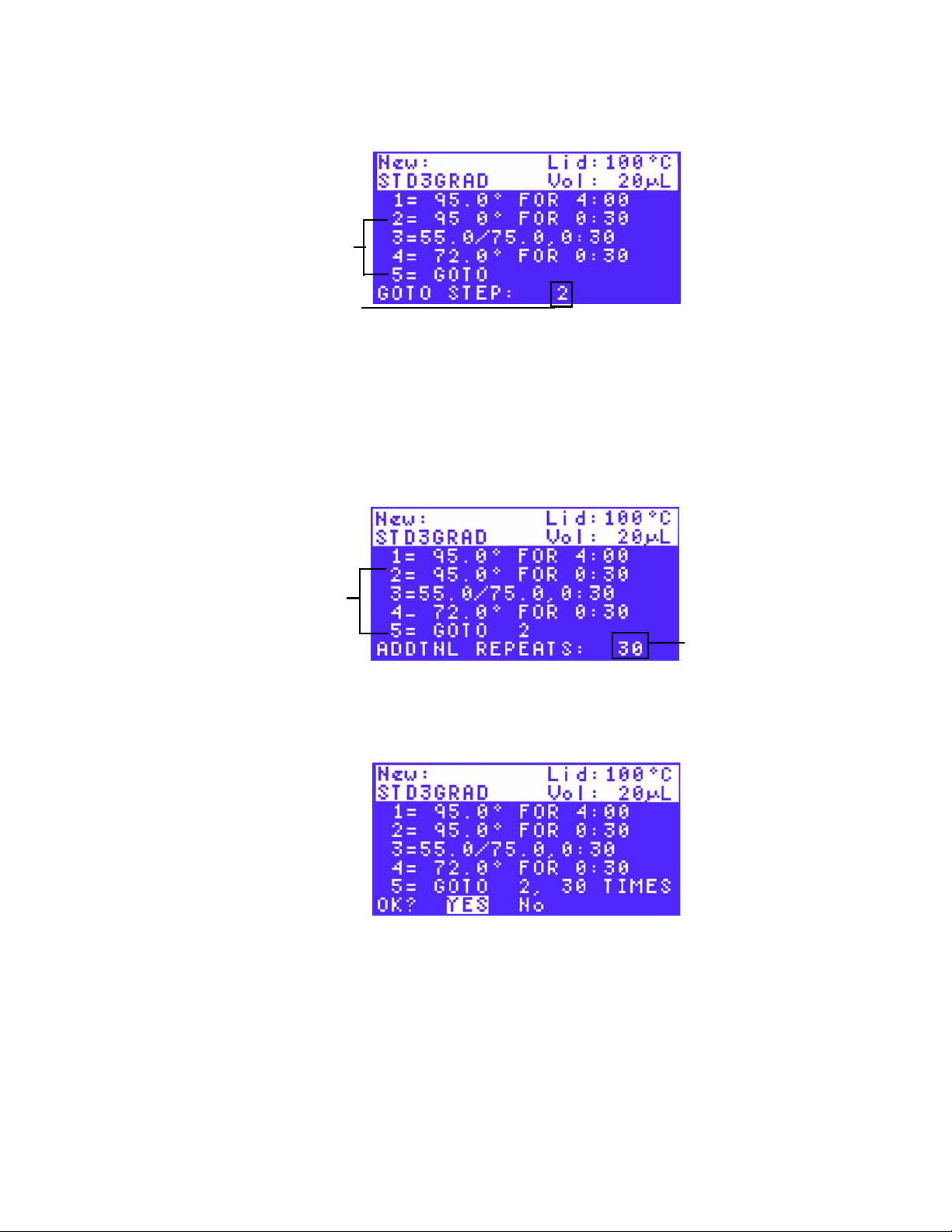
16.Enter the step number for the first step in the GOTO repeats using the numeric keys.
Press ENTER to continue to the next screen.
Page 26
S1000 Thermal Cycler Manual
In Figure 25, the first step is 2. The GOTO step instructs the thermal cycler to return to
step 2 and repeat all the steps between steps 2 and 5.
Steps that
repeat during
GOTO step
First step in
GOTO repeats
Figure 25. Enter the first step in the GOTO repeats.
17.Enter the number between 1 and 9999 for the additional repeats (ADDTNL REPEATS) in
the GOTO step. Then press ENTER to continue to the next screen.
NOTE: The GOTO step adds additional cycles to the PCR protocol. The first cycle
is not included in the GOTO step. For example, to run a PCR protocol with 31
cycles, enter 30 repeats in the GOTO step.
In Figure 26, the number of repeats is 30, and the total number of cycles is 31.
Steps that
repeat in the
GOTO step
Figure 26. Enter the number of repeats in a GOTO step.
18.Select YES to accept the GOTO step parameters (Figure 27), or select No to return to
the beginning of this step and change the GOTO step parameters. Then press ENTER to
continue to the next screen.
Figure 27. Confirm a GOTO step by selecting YES.
19.Enter the remaining steps by choosing the step type and adding parameters. Then press
ENTER to continue to the next screen.
TIP: To instruct the thermal cycler to emit a sound at the end of the protocol,
include a BEEP option in the final temperature step (page 21).
Number of
additional repeats
in a GOTO step
17
Page 27
Creating a New Protocol
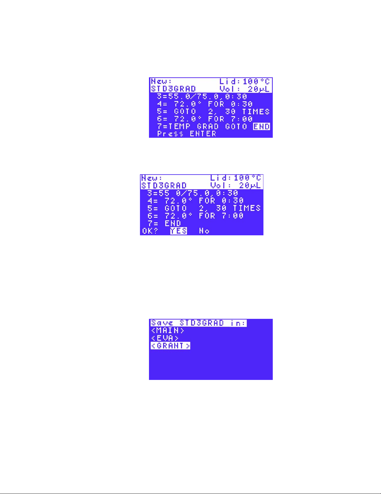
20.Select END using the arrow keys to instruct the thermal cycler to finish the protocol file.
Press ENTER to continue to the next screen. In Figure 28, the END step is selected.
NOTE: The END step must be the last step of a protocol; a protocol can only
contain one END step.
21.Select YES (Figure 29) to accept the protocol step parameters or No to return to the
beginning and select a different protocol step.
Figure 28. The END step in a protocol.
Figure 29. Select YES to accept the protocol parameters.
22.Use the arrow keys to select the folder where you want the new protocol file to be saved,
and press ENTER to save the protocol file.
NOTE: The file tree folder screen does not appear if there are no user-created
folders (i.e. the MAIN folder is the only folder on the list). Saving the protocol in the
MAIN folder is not recommended. If the protocol is saved in the MAIN folder, we
recommend moving it to a user-created folder. (See “Moving a Protocol File” on
page 41 for more information.)
In Figure 30, the STD3GRAD file is saved in the GRANT
Figure 30. The STD3GRAD file is to be saved in the GRANT folder.
To run a protocol, follow the instructions in “Preparing to Run a Protocol” on page 29.
folder.
18
Page 28

S1000 Thermal Cycler Manual
Parameters for Temperature or Gradient Steps
Table 10 includes a list of options for temperature and gradient steps for the S1000 thermal
cycler. The table also includes the limits and range of the parameters.
Table 10. Options and parameters for protocols on the S1000 thermal cycler
Step Name Parameters and Ranges Description
INC
(Increment)
EXT
(Extend)
RATE
(Ramp rate)
Beep (No parameters) Applies only to a temperature step (see
A temperature from –10.0 to
10.0°C per cycle in tenths of a
degree
A time from –60 to 60 sec per
cycle
A number from 0.1 to 5°C per
sec
Applies only to a temperature step (see
“Adding an Increment to a
Temperature Step” on page 19).
Instructs the thermal cycler to
increment (change) the target
temperature of a step with each cycle,
where a positive number increases the
temperature and a negative number
decreases the temperature
Applies to both temperature and
gradient steps (see “Extending the
Hold Time in a Temperature Step” on
page 20). Instructs the thermal cycler
to extend the hold time with each
cycle. A positive number increases the
hold time and a negative number
decreases the hold time
Applies only to a temperature step (see
“Changing the Ramp Rate in a
Temperature Step” on page 21).
Instructs the thermal cycler to ramp to
the target temperature at the specified
ramp rate in that step
“Adding a Beep to a Temperature
Step” on page 21). Instructs the
thermal cycler to beep to signal that
the thermal cycler has reached the
target temperature for that step
Adding an Increment to a Temperature Step
The increment (INC) parameter changes the target temperature of a protocol step. The
increment can increase or decrease the target temperature with each cycle in the protocol.
To add an increment:
1. Select OPTION using the arrow keys. Press ENTER to continue to the next screen.
19
Page 29
Parameters for Temperature or Gradient Steps
In Figure 31, OPTION is selected to add an increment to a temperature step.
Figure 31. Select OPTION to add an increment to a temperature step.
NOTE: The INC parameter must be added to a step within the GOTO repeats in
order to increment with each cycle of the reaction.
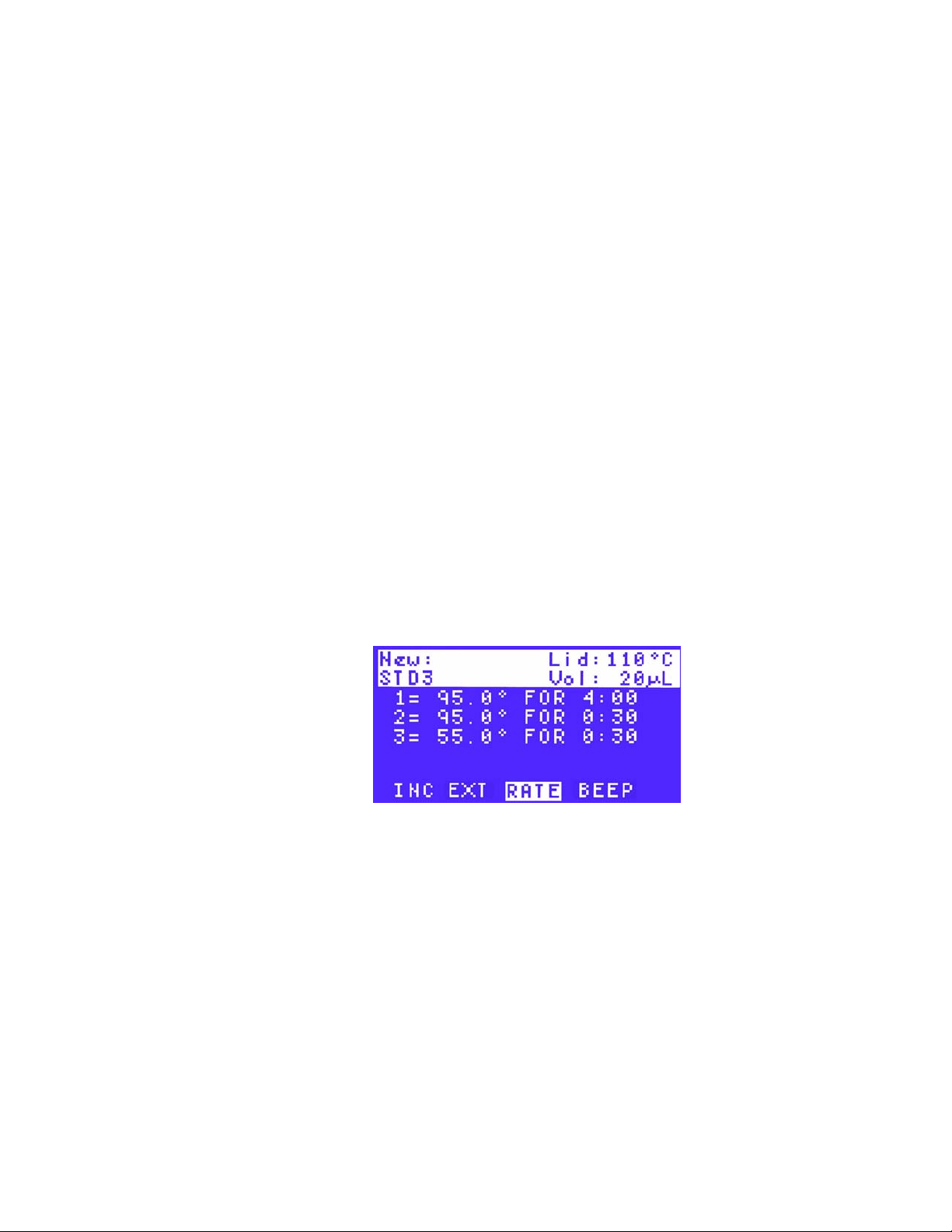
2. Select INC using the arrow keys (Figure 32) to add an increment to the protocol step in
each cycle. Press ENTER to continue to the next screen.
Figure 32. Select INC to add an increment.
3. Enter the increment temperature using the numeric keys. To decrease the temperature
each cycle, enter a negative number by pressing the CANCEL (–) key. Press the PAUSE
(
.
) key to enter a decimal point. Then press ENTER to continue to the next screen.
NOTE: Enter an increment from –10.0 to 10.0°C per cycle in tenths of a degree,
and within the limits of a temperature step (0–100°C).
In Figure 33, the increment is +0.5°C. The target temperature for step 3 will increase by
0.5°C each cycle.
Figure 33. Enter the increment temperature.
4. To confirm the parameters of the protocol step, select YES and then press ENTER. To
change the parameters, select No and then press ENTER.
Extending the Hold Time in a Temperature Step
20
The EXT parameter changes the hold time for a temperature or gradient temperature step. The
extension increases or decreases the hold time with every cycle.
Page 30
S1000 Thermal Cycler Manual
To add an extension:
1. Select OPTION using the arrow keys. Press ENTER to continue to the next screen.
2. Select EXT using the arrow keys to add an increment to the protocol step in each cycle.
Press ENTER to continue to the next screen.
NOTE: The EXT option must be added to a step within a GOTO repeat in order to
extend with each cycle of the reaction.
3. Enter the extension time in seconds using the numeric keys. To decrease the hold time in
each cycle, enter a negative number by pressing CANCEL (–). Then press ENTER to
continue to the next screen.
NOTE: Enter an extension time from –60 to 60 seconds per cycle in whole
numbers. The time entered must be between tenths of a degree. This value should
also be within the limits of a temperature step, which is 1 second to 18 hours.
4. To confirm the parameters of the protocol step, select YES and then press ENTER. To
change the parameters, select No and then press ENTER.
Changing the Ramp Rate in a Temperature Step
The RATE parameter changes the ramp rate of a temperature step. The ramp rate is the rate at
which the thermal cycler heats or cools to the target temperature of a step.
To change the rate, follow these instructions:
1. Select OPTION after entering the initial temperature step parameters, and then press
ENTER to continue to the next screen.
2. Select RATE to change the ramp rate (Figure 34). Press ENTER to continue to the next
screen.
Figure 34. Select RATE to change the ramp rate.
3. Enter a ramp rate (in °C/sec) using the numeric keys. Press PAUSE (
point.
NOTE: Enter a ramp rate between 0.1 and 5°C/sec in tenths of a degree.
4. To confirm the parameters of the protocol step, select YES and then press ENTER. To
change the parameters, select No and then press ENTER.
.
) to enter a decimal
Adding a Beep to a Temperature Step
The BEEP parameter instructs the thermal cycler to emit a sound when the temperature
reaches its target. A
TIP: Add the beep step to a temperature step, such as an infinite (FOREVER) hold,
to have the thermal cycler give a signal when it initiates the step.
BEEP can be added to any temperature step.
21
Page 31

Editing an Existing Protocol
To add a beep:
1. Select OPTION after entering the initial temperature step parameters, and then press
ENTER to continue to the next screen.
2. Select BEEP to signal the end of the protocol step. Press ENTER to continue to the next
screen.
NOTE: The BEEP parameter can only be added to a temperature step.
3. To confirm the parameters of the protocol step, select YES and then press ENTER. To
change the parameters, select No and then press ENTER.
Editing an Existing Protocol
NOTE: A protocol that is already running cannot be edited. Changes made in a
protocol that is running apply to the next time the protocol runs. To stop editing a
protocol, press CANCEL several times.
Editing the Lid Temperature and Sample Volume
To edit an existing protocol:
1. Select EDIT from the main menu (Figure 35). Press ENTER to confirm the selection.
Figure 35. Select EDIT from the main menu.
2. Using the arrow keys, select the folder that contains the protocol file to be edited. Press
ENTER to continue to the next screen.
In Figure 36, the file named STD3 is selected in the folder named EVA.
Figure 36. THE STD3 file in the EVA folder is selected.
3. Enter the new lid temperature (optional) or use the default lid temperature. Press ENTER
to accept the lid temperature and continue to the next screen.
NOTE: The lid temperature can range from 0 to 110°C. When the block is running
an infinite hold at a temperature below the Turn off below parameter, the lid heater
maintains 31.0°C. To change the default Turn off below parameter, select TOOLS
> DEFAULTS.
22
Page 32

S1000 Thermal Cycler Manual
4. Enter a new sample volume (optional) or use the default volume. Press ENTER to
continue to the next screen.
NOTE: Entering a sample volume between 1 and 50 selects Calculated
Temperature control mode, which is the standard mode. Entering zero (0) in the
volume field selects Block mode. Calculated mode is the recommended mode
because it most accurately represents the actual sample temperature. For more
information about temperature control modes, see page 27.
Inserting a Protocol Step
1. Select EDIT from the main menu (Figure 37). Press ENTER to confirm the selection.
Figure 37. Select EDIT from the main menu.
2. Using the arrow keys, select the folder that contains the protocol file to be edited. Press
ENTER to continue to the next screen.
3. Select a protocol step to edit using the arrow keys. Press ENTER to continue editing the
step.
In Figure 38, step 4 is selected for editing.
Figure 38. Select the protocol step to be edited.
4. Select INS to insert a step above the selected protocol step. In Figure 39, INS is selected
to insert a step above step 4.
Selected step
Choose a method
Figure 39. INS is selected to insert a step above step 4.
5. Select TEMP, GRAD, or GOTO as the type of protocol step to be inserted. Press ENTER
to continue to the next screen.
23
Page 33

Editing an Existing Protocol
In Figure 40, a temperature step (TEMP) is selected.
Figure 40. TEMP is selected as the type of protocol step to be inserted.
6. Enter the step parameters, then press ENTER to confirm each parameter.
In Figure 41, the target temperature of 72°C is entered.
Figure 41. The temperature of the inserted step is entered.
7. (Optional) Enter more step parameters by selecting OPTION. For example, add an
increment or extension to this temperature step. For more instructions about entering
additional parameters to a step, see “Parameters for Temperature or Gradient Steps” on
page 19.
In Figure 42, OPTION is selected to add parameters to step 4.
Figure 42. Select OPTION to add additional parameters.
8. Enter the parameters of the new step. Then press ENTER to confirm each parameter.
Deleting a Protocol Step
1. Select EDIT from the main menu. Press ENTER to confirm the selection.
2. Using the arrow keys, select the folder that contains the protocol file to be edited. Press
ENTER to continue to the next screen.
24
3. Select a protocol step to delete using the arrow keys. Press ENTER to continue editing
the step.
4. Select DEL to delete the selected protocol step. In Figure 43, step 4 is selected to
delete. Press ENTER to continue to the next screen.
Page 34

S1000 Thermal Cycler Manual
In Figure 43, step 4 is selected to be deleted.
Figure 43. Select DEL to delete a protocol step.
ENTER
5. Delete the selected step. Press
screen. Notice that the deleted step parameters are replaced with the parameters of the
next step.
6. Confirm the deletion. When prompted with Save changes?, select YES and press
ENTER to delete the step. Alternatively, select No and press ENTER to return to the
beginning of this step.
In Figure 44, YES is selected.
to delete the step and continue to the next
Figure 44. Select YES to delete the selected step.
Editing a Protocol Step
To change the parameters in the existing protocol steps, use the following instructions:
1. Select EDIT from the main menu. Press ENTER to confirm the selection.
2. Using the arrow keys, select the folder that contains the protocol file to be edited. Press
ENTER to continue to the next screen.
3. Select a protocol step to delete using the arrow keys. Press ENTER to continue editing
the step.
4. Select EDIT to delete the selected protocol step. Press ENTER to continue to the next
screen.
TIP: When you first select EDIT
protocol step. To edit the parameters in a different protocol step, press the arrow
keys to go to that step.
,
you can edit the parameters in the selected
25
Page 35

Editing an Existing Protocol
In Figure 45, step 4 is selected to be deleted. Notice the original parameter for
temperature is 55°C.
Choose EDIT
5. Change the first parameter in the step by pressing the keys on the control panel to enter
the temperature. Then press ENTER to continue to the next parameter.
In Figure 46, the temperature is changed from 55 to 65°C.
Original
parameters
Figure 45. Select EDIT to delete a protocol step.
Figure 46. Enter a new temperature.
6. Change the second parameter in the step by pressing the numeric keys to type a new
parameter. Then press
In Figure 47, the hold time is changed to 35 seconds.
7. Continue editing the existing parameters in each step (optional). Press the up and down
arrow keys to choose an earlier or later step in the protocol.
ENTER
to continue to continue to the next step.
Figure 47. Enter a new hold time.
Enter a new
parameter
26
Page 36

In Figure 48, the temperature parameter is changed to 70.0°C in step 4.
Enter new
parameter
in next step
Figure 48. The temperature parameter is changed from 72.0°C to 70.0°C.
8. Press ENTER to finish changing parameters in the step and to continue editing the
protocol.
Sample Volume and Lid Temperature
The sample volume and lid temperature influence the outcome of a PCR protocol.
• Sample volume — determines the temperature control mode, which influences the
amount of time the samples are held at the target temperature
• Lid temperature settings — determine the temperature of the heated lid and when it
cuts off. If the temperature is too high, the sample temperature might rise above the
target temperature
S1000 Thermal Cycler Manual
The S1000 thermal cycler provides various ways of managing and entering sample volume
and lid temperature settings:
• Change the setting when creating a protocol (page 12)
• Change the settings when editing the protocol (page 22)
• Change the settings when preparing to run a protocol (page 29)
Temperature Control Modes
The S1000 thermal cycler uses one of two temperature control modes to determine when the
sample reaches the target temperature:
• Calculated mode — the thermal cycler calculates the sample temperature based on
the sample volume when a sample volume between 1 and 50 µl is entered for 96- or
dual 48-well reaction modules or a volume between 1 and 30 µl is entered for the
384-well reaction module. The calculated mode is recommended, because it most
accurately represents the actual sample temperature
• Block mode — when a sample volume of zero (0) µl is entered, the thermal cycler
assumes that the sample temperature is the same as the measured block
temperature
Choosing the Appropriate Lid Temperature
The adjustable heated lid of the reaction module allows the user to control the lid temperature
and force. Heating the lid prevents condensation from forming inside the tubes and plates.
When the S1000 thermal cycler is running, the heated lid maintains the temperature specified
for the protocol being run. Without a heated lid, water can be lost from the reagents to
condensation, concentrating the reactants in the tube or plate.
27
Page 37

Sample Volume and Lid Temperature
The default lid temperature of the S1000 thermal cycler is 105°C for 96- or dual 48-well
reaction blocks and 95°C for 384-well blocks.
NOTE: When the block is running an infinite hold at a temperature below the Turn
off below parameter, the lid heater maintains 31.0°C. The default Turn off below
setting is 30.0°C. To change the default Turn off below, select Tools > Defaults.
28
Page 38

S1000 Thermal Cycler Manual
3 Running Protocols
Read this chapter for information on setting up the S1000 thermal cycler.
• Preparing to run a protocol (below)
• Monitoring the protocol run (page 32)
• Pausing and resuming a run (page 33)
• Skipping a step during a run (page 34)
• Canceling a run (page 34)
• Incubating samples (page 35)
Preparing to Run a Protocol
NOTE: You can run a protocol in a secure folder without entering the password
first. See “Securing Files in a Folder” on page 43 for more information about files in
secure folders.
To run a protocol:
1. Load the samples in the block. Close the lid and set the lid force using instructions on
page 8.
2. Select RUN from the main menu. Press ENTER to confirm the selection and continue to
the next screen.
NOTE: The main menu status should show Block is idle (Figure 49). With a dual
48/48 reaction module, the status message is Block are idle when the blocks are
both available to run a protocol.
Figure 49. Select RUN from the main menu.
29
Page 39
Preparing to Run a Protocol
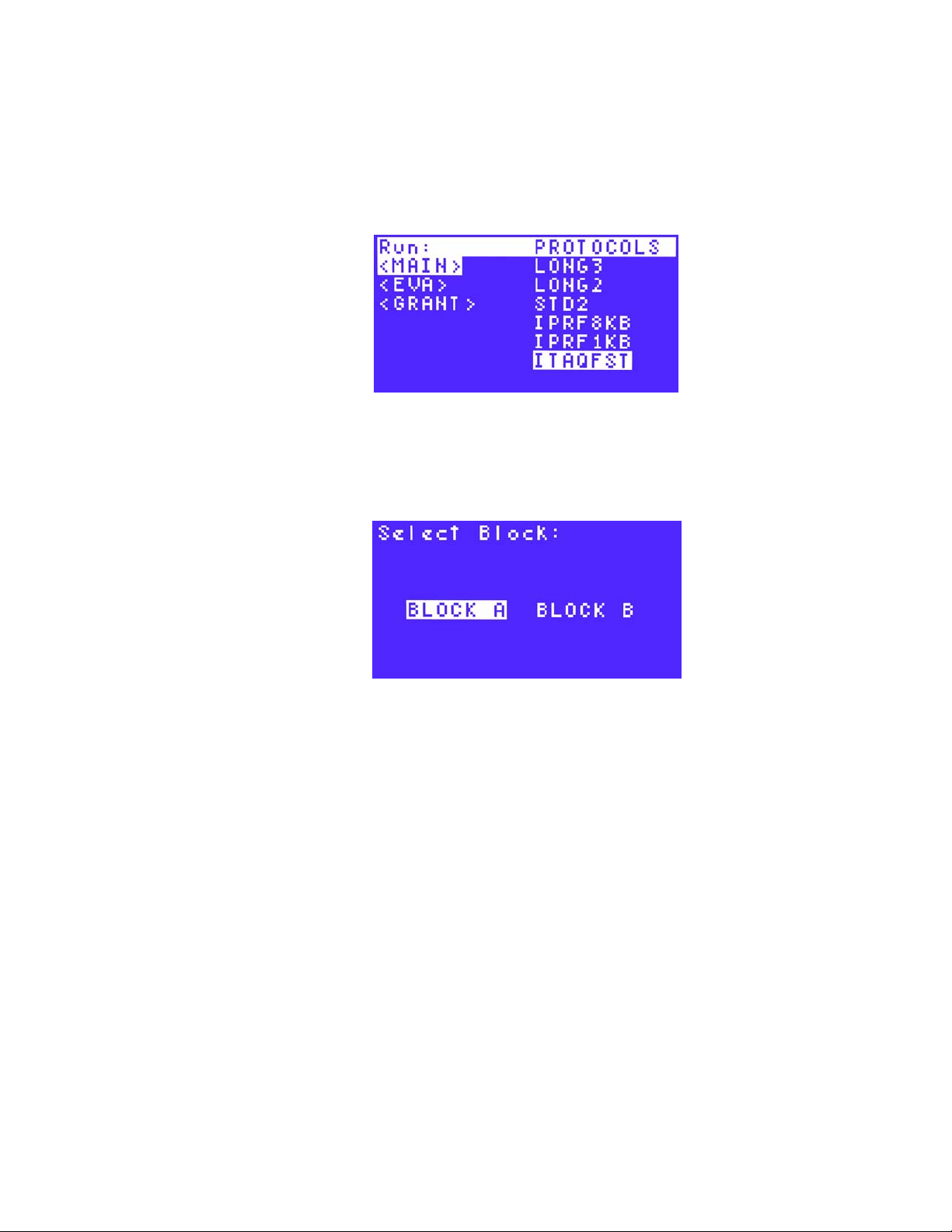
3. Select a folder that contains the protocol file of interest, and then press the right arrow
key to select the file. Press ENTER to confirm the selection and continue to the next
screen.
NOTE: Select a protocol from the preinstalled protocols from the MAIN folder or
any user folder in the file tree.
In Figure 50, the preinstalled protocol ITAQFAST is selected in the MAIN folder.
4. Select BLOCK A or BLOCK B using the right and left arrow keys. Press ENTER to
continue to the next screen. In Figure 51, BLOCK A is selected
NOTE: When a block is selected, the LED on the reaction module lights up. In a
dual 48/48 reaction module, BLOCK A appears on the left side.
Figure 50. Select the folder and protocol file.
Figure 51. Block A is selected.
5. Enter the sample volume. To use the Calculated mode (standard), enter a value between
1 and 50 µl. To use Block mode, enter 0 (zero).
NOTE: Calculated mode is the recommended temperature control mode because
it most accurately represents the actual sample temperature. See “Temperature
Control Modes” on page 27.
6. Press the numeric keys to enter a new sample volume, then press ENTER to continue to
the next screen.
30
Page 40

S1000 Thermal Cycler Manual
In Figure 52, the sample volume is 25 µl.
Figure 52. Enter a new sample volume.
NOTE: When running a dual block, the message is RUN ITAQFST on A, where
ITAQFST is the protocol and A is the block.
7. (Optional) Select VIEW to review the protocol before starting the run (Figure 53), and
press ENTER to confirm the selection.
Figure 53. Select VIEW to review the protocol.
NOTE: While reviewing the protocol, press ENTER to scroll down through the
steps in the protocol. When you reach the last step in the protocol, press ENTER
again to exit. In Figure 54, the screen shows the steps in the ITAQFST protocol.
Figure 54. View the steps of the protocol.
8. Select RUN using the arrow keys (Figure 55), and press ENTER to start running the
protocol.
Figure 55. Select RUN to start running the protocol
31
Page 41

Monitoring the Protocol Run
Monitoring the Protocol Run
Once the run begins, the progress of the run can be monitored with any one of the following
screens:
• Running screen – displays the current step parameters, temperature, hold time,
and cycle (Figure 56)
• Graphical screen – displays a graph that approximates the relationship of the
target temperatures in each step in the protocol. Each step is listed by
temperature only (Figure 57)
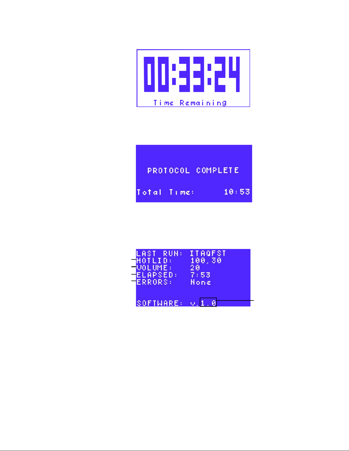
• Time Remaining screen – shows the amount of time remaining until the end of
the protocol (Figure 58)
To monitor the run:
1. Press SCREEN on the control panel.
The Running screen appears as a default (Figure 56). If SCREEN is pressed again, the
instrument shows graphical screen (Figure 57). Press SCREEN again to see the Time
Remaining screen (Figure 58).
NOTE: For the dual 48/48 reaction module, the thermal cycler displays these
screens for Block A and then for Block A. Pressing SCREEN toggles the display
through each screen and both blocks.
.
Protocol steps
(by temperature)
Target temperature
for the current step
Figure 56. The Running screen is displayed.
Hold time for current step (counts up)
Figure 57. The graphical screen is displayed.
Current hold time
Current
temperature
Flashing thick
bar shows
current step
32
Page 42
S1000 Thermal Cycler Manual
Figure 58. The Time Remaining screen.
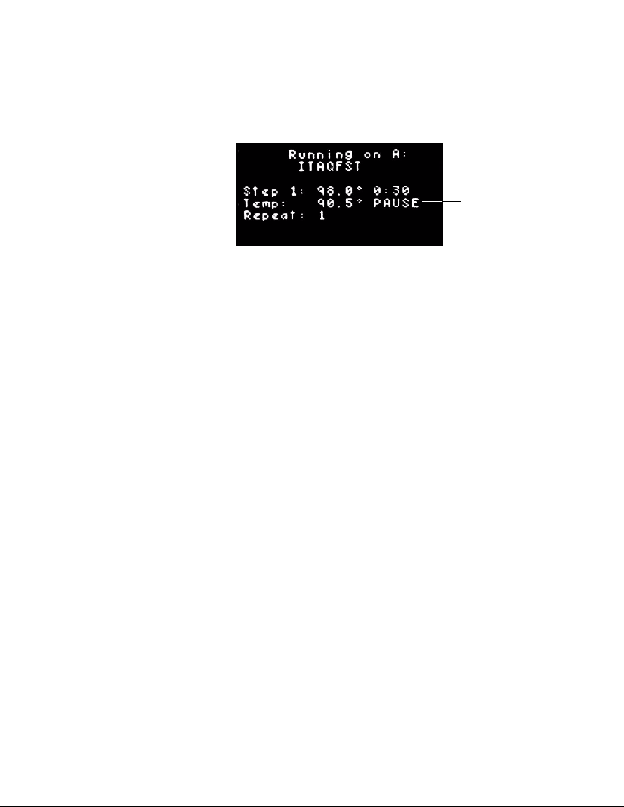
2. When the S1000 thermal cycler completes running the protocol, the PROTOCOL
COMPLETE screen is displayed (Figure 59). After viewing this screen, press ENTER to
return to the main menu.
Figure 59. PROTOCOL COMPLETE screen is displayed with the run is completed.
3. (Optional) Press SCREEN to see a synopsis of the last protocol that was run. The
protocol summary is displayed on the LAST RUN screen (Figure 60).
NOTE: For dual 48/48 blocks, press SCREEN again to view the LAST RUN screen
for each block.
Lid temperature
Sample volume
Total run time
Errors that occurred
during the run
Figure 60. Summary of the last protocol is listed on the LAST RUN screen.
TIP: The LAST RUN screen is also available in the TOOLS option (page 53).
4. Press SCREEN
again to return to the main menu
Pausing and Resuming a Run
A running protocol may be temporarily paused. During a pause, the thermal cycler maintains
the block temperature at the current target temperature. If the block temperature has not
reached the target temperature, then the thermal cycler continues to heat or cool until it
reaches that target temperature.
Firmware used
during run
33
Page 43
Skipping a Step During the Run
WARNING! Pausing a protocol can alter the results of your PCR experiment. When
a protocol is paused during a temperature step, a longer hold time is created for
that step.
To pause and then resume a running protocol:
1. Press PAUSE on the control panel (Figure 61).
Figure 61. The protocol is paused.
2. To resume the protocol, press PAUSE again.
Skipping a Step During the Run
Protocol
paused
To skip a step while the protocol is running:
1. Press ENTER when the step to be skipped is running.
The thermal cycler skips to the next step in the protocol.
TIP: The S1000 thermal cycler cannot skip a GOTO repeat, unless the instrument is
controlled by a C1000 thermal cycler.
2. Press the right and left arrow key to select YES or No.
3. Press ENTER again to confirm the selection.
Canceling a Run
A protocol may be cancelled while it is running. When a protocol is cancelled, the block
immediately stops changing the temperature.
To cancel a running protocol:
1. Press CANCEL, then press the arrow key to select YES or No.
34
Page 44

S1000 Thermal Cycler Manual
2. Press ENTER to confirm the selection, and continue to the next screen. In Figure 62,
YES is selected.
Figure 62. Select YES to cancel a running protocol.
TIP: To cancel a protocol that is running on a dual 48/48 reaction module, press
CANCEL and then select the block that you want to cancel the run on. Press
ENTER to confirm the protocol cancellation.
The PROTOCOL CANCELLED screen appears. This screen displays the total time that
the protocol ran before being cancelled. In Figure 63, the protocol has run 2 minutes and
57 seconds.
Figure 63. The PROTOCOL CANCELLED screen.
3. Press ENTER again to return to the main menu
Incubating Samples
Samples may be kept at a constant temperature for any amount of time. The incubation
continues indefinitely unless cancelled.
WARNING! Incubating samples for an extended period of time at 4–10°C,
particularly in areas of high humidity, can cause excessive moisture condensation
around the block.
To start incubating samples:
1. Load your samples into the thermal cycler block and press INCUBATE.
NOTE: For the dual 48 reaction module, the block that contains the samples must
first be selected before continuing to the next screen.
35
Page 45

Incubating Samples
2. Select YES to use the heated lid during the incubation or No to turn off the lid during
incubation. Press ENTER to confirm. In Figure 64, YES is selected.
3. If using the heated lid, enter the lid temperature. Press ENTER to accept the default lid
temperature, or use the numeric keys to type a new lid temperature.
NOTE: Press PAUSE (
CANCEL.
In Figure 65, the lid temperature is 100°C.
Figure 64. Select YES to use the heated lid during the incubation.
.
) key to enter a decimal point. To delete a number, press
Figure 65. Enter the lid temperature.
4. Enter the incubation temperature. Press ENTER to accept the default incubation
temperature of 75°C, or use the numeric keys to type a new incubation temperature
between 0 and 100°C.
NOTE: Press PAUSE (
CANCEL.
In Figure 66, the incubation temperature is 95°C.
.
) to enter a decimal point. To delete a number, press
Figure 66. Enter the incubation temperature.
36
Page 46

S1000 Thermal Cycler Manual
5. Press ENTER to start the incubation. In Figure 67, the block is incubating at 95.0°C.
Incubation
temperature
Figure 67. The incubation temperature is 95.0°C.
TIP: During incubation, use any options in the main menu except RUN. You cannot
start a run on a block that is running an incubation.
6. To stop an incubation, press CANCEL.
7. Select YES to stop the incubation or No to continue the incubation. Press ENTER to
confirm the selection and return to the main menu. In Figure 68, YES is selected.
Figure 68. Select YES to cancel a protocol.
8. Press SCREEN three times to view the incubation parameters summarized in the LAST
RUN screen (Figure 69).
Figure 69. The incubation parameters are summarized in the LAST RUN screen.
37
Page 47

Incubating Samples
38
Page 48

S1000 Thermal Cycler Manual
4 Managing Protocol Files and
Folders
Read this chapter for information on managing protocol files and folders.
Managing Protocol Files and Folders
To manage protocol files and folders, select FILES from the main menu to open the file library
Figure 70). The menu of functions in the file library provides options for managing files and
(
folders and changes based on what is selected in the file library.
Folder
functions
Figure 70. Options for managing protocol files and folders.
Table 11 lists all the functions in the FILES option. Protocol and folder names can have a
maximum of 8 characters.
Table 11. List of functions in the FILES option
Function Description
PROTOCOLS
COPY
MOVE
DELETE
RENAME
Copies an existing protocol file and saves it with a new name
Moves a protocol file to another folder
Deletes a protocol file
Renames a protocol file
Protocol file
functions
FOLDERS
NEW
Creates a new folder
39
Page 49

Managing Protocol Files and Folders
Table 11. List of functions in the FILES option (continued)
Function Description
SECURE
DELETE
RENAME
Copying a Protocol File
To copy a protocol file:
1. Select FILES from the main menu.
2. Select COPY using the arrow keys (Figure 71), then press ENTER to confirm the
selection.
NOTE: The COPY function makes a copy of the existing file and requires a new file
name for the copied file. You can copy and move secured or preinstalled protocols
to your folder.
Protected files can be deleted and edited once the password
protecting them is entered
Deletes an empty folder.
NOTE: A folder cannot be deleted if it contains protocol files.
Renames an existing folder
Figure 71. Select COPY using the arrow keys.
3. Using the arrow keys, select the folder that contains the protocol file to be copied, then
press the right arrow key to select the appropriate file. Press ENTER to continue to the
next screen.
In Figure 72, the STD2 protocol file is selected in the MAIN folder.
Figure 72. The STD2 protocol file is selected for copying.
40
Page 50

S1000 Thermal Cycler Manual
4. Using the arrow keys, select the destination folder. In Figure 73, the copied file is placed
into the GRANT folder. Press ENTER to confirm that the protocol was successfully
copied.
Figure 73. Select the destination folder.
5. Type a new name for the protocol copied file by pressing the up and down arrows to
select letters and the numeric keys to type numbers (Figure 74). Press ENTER to accept
the selection.
NOTE: A protocol file name can contain 1–8 characters. The characters are
numbers or capital letters. Each protocol name must be unique.
Figure 74. The protocol was successfully copied.
TIP: After copying the protocol file, make changes to the file by selecting EDIT in
the main menu (page 22).
Moving a Protocol File
NOTE: If the folder is secure, then you must enter a password to move the file.
However, the protocols in a secure folder can be copied to another folder.
To move a protocol file to another folder:
1. Select Files from the main menu.
2. Select MOVE using the arrow keys (Figure 75), then press ENTER to confirm the
selection.
Figure 75. Select MOVE using the arrow keys.
41
Page 51

Managing Protocol Files and Folders
3. Using the arrow keys, select the folder that contains the protocol file to be moved, then
press the right arrow key to select the appropriate file. Press ENTER to continue to the
next screen.
4. Using the arrow keys, select the destination folder. Press ENTER to confirm the move.
Deleting a Protocol File
NOTE: If the folder is secure, then you must enter a password to delete the file.
To delete a protocol file:
1. Select FILES from the main menu.
2. Select DELETE using the arrow keys (Figure 76), then press ENTER to confirm the
selection.
.
Figure 76. Select DELETE to delete a protocol file.
3. Using the arrow keys, select the folder that contains the protocol file to be deleted, then
press the right arrow key to select the appropriate file. Press ENTER to continue to the
next screen.
4. To delete the file, select YES and then press ENTER to return to the main menu. Select
No to cancel the deletion.
Renaming a Protocol File
To rename a protocol file:
1. Select FILES from the main menu.
2. Select RENAME using the arrow keys (Figure 77), then press ENTER to confirm the
selection.
42
Figure 77. Select RENAME to enter a new protocol name.
Page 52

S1000 Thermal Cycler Manual
3. Using the arrow keys, select the folder that contains the protocol file to be renamed, then
press the right arrow key to select the appropriate file. Press ENTER to continue to the
next screen.
4. Enter a new protocol file name using the up and down arrows to select letters and the
numeric keys to type numbers. Then press ENTER to accept the new name and return to
the main menu.
NOTE: A protocol file name can contain 1–8 characters. The characters are
numbers or capital letters. Each protocol name must be unique to all folders on the
S1000 thermal cycler.
Creating a New Folder
The S1000 thermal cycler can contain 11 folders in addition to the MAIN folder. Protocol files
are stored in the MAIN folder by default; however, it is highly recommended that files be
stored in user-created folders for easy access and ability to password-protect the files.
To create a new folder:
1. Select FILES from the main menu.
2. Select NEW from the menu using the arrow keys (Figure 78). Press ENTER to confirm the
selection.
Figure 78. Select NEW to create a new folder.
3. Enter the folder name using the up and down arrows to select letters and the numeric
keys to type numbers. Then press ENTER to accept the new name and return to the
main menu.
NOTE: A folder name can contain 1–8 characters. The characters are numbers or
capital letters. Each protocol name must be unique to the thermal cycler.
Securing Files in a Folder
Securing folders with a password prevents other users from editing, deleting, or moving your
files from the S1000 thermal cycler.
NOTE: To edit, move, or delete files stored in a secure folder, a password must be
entered. However, a password is not required for viewing, copying, or running
protocol files that are located in a secure folder.
To secure a folder with a password or to change an existing password:
1. Select FILES from the main menu.
43
Page 53

Managing Protocol Files and Folders
2. Select SECURE using the arrow keys (Figure 79). Press ENTER to confirm the selection
and continue to the next screen.
Figure 79. Select SECURE to secure a folder with a password.
3. Select the folder to be secured using the up and down arrows.
NOTE: To change a password, you need to enter the original password first. If the
password is lost, protocols in the secured folder cannot be deleted, moved, or
edited. Furthermore, the folder cannot be deleted.
4. Enter a new password using the numeric keys to type numbers. Press ENTER to confirm
the password, and return to the main menu.
NOTE: A password can contain one to four numbers, and cannot contain letters.
TIP: To disable security for a folder, repeat steps 1–4, and specify a blank, new
password.
Deleting a Folder
NOTE: A folder that contains protocol files cannot be deleted. Select VIEW in the
main menu to view the contents of the folder before deleting the folder. Delete or
move all protocol files before deleting the folder. Once a folder is deleted, it is
permanently removed.
To delete a folder:
1. Select FILES from the main menu.
2. Select DELETE using the arrow keys (Figure 80), then press ENTER to confirm the
selection.
Figure 80. Select DELETE to permanently remove a folder.
3. Using the arrow keys, select the folder to be deleted. Press ENTER to continue to the
next screen.
44
4. To delete the folder, select YES and then press ENTER to return to the main menu.
Select No to cancel the deletion
Page 54

S1000 Thermal Cycler Manual
Renaming a Folder
NOTE: Renaming a folder does not change the protocol files stored in the folder.
To rename a folder that is secure, enter the password before typing the name.
To rename a folder:
1. Select FILES from the main menu.
2. Select RENAME using the arrow keys (Figure 81), then press ENTER to confirm the
selection.
.
Figure 81. Select RENAME using the arrow keys.
3. Using the arrow keys, select the folder to be renamed. Press ENTER to continue to the
next screen.
4. Enter the new folder name using the up and down arrows to select letters and the
numeric keys to type numbers. Then press ENTER to accept the new name and return to
the main menu.
NOTE: A folder name can contain 1–8 characters. The characters are numbers or
capital letters.
45
Page 55

Managing Protocol Files and Folders
46
Page 56

S1000 Thermal Cycler Manual
5 Optimizing PCR on the S1000
Thermal Cycler
Read this chapter for information on optimizing PCR on the S1000 thermal cycler.
• Optimizing a protocol for faster PCR (below)
• Optimizing annealing temperature step with a gradient (page 49)
• Optimizing PCR with small sample volumes (page 50)
• Transferring protocols from another thermal cycler (page 50)
• Troubleshooting PCR problems (page 50)
• Selecting compatible reaction vessels and sealing options (page 51)
Optimizing a Protocol for Faster PCR
Optimizing a protocol for faster PCR can reduce the total run time by one-third. In contrast,
running the same protocol on a thermal cycler with a faster ramp rate only cuts minutes from
the total run time. Optimizing the protocol for speed can also result in better PCR results.
Complete optimization of a protocol involves selecting the appropriate reagents, enzymes,
and primers, as well as testing the parameters of the PCR protocol. For more detailed
information on optimizing protocols for fast PCR, refer to the following resources:
• Gene Expression Gateway (www.bio-rad.com/genomics/). Go to the web site and
select Application | Techniques > Quantification > Fast PCR
• BioRadiations Magazine volume 118 in PDF. Go to discover.bio-rad.com and search
the Literature for “Fast PCR”. This magazine includes articles on tips for optimizing the
reagents
To optimize a protocol for fast PCR using the S1000 thermal cycler, follow these guidelines:
• Shorten the denaturing step during cycling
The initial denaturation step requires a longer hold time than denaturing steps during
each subsequent cycle. This difference is due to the activation of polymerase and to the
longer initial DNA template. Once the PCR target is amplified, the amplicons then serve
as shorter templates that are easier to denature during cycling.
To shorten the denaturation step, enter a hold time of 1 sec for PCR products that are
less than 500 bp. Then test this shorter hold time to verify that a 1 sec denaturation is
sufficient to produce amplicons. Alternatively, add an increment to the denaturation step
47
Page 57

Optimizing a Protocol for Faster PCR
to test for the best hold time. See “Adding an Increment to a Temperature Step” on
page 19 for detailed instructions.
• Create a two-step protocol by combining annealing and extension into a single
step
Most polymerases remain active throughout the typical range of annealing temperatures
(55–70°C). Reduce the total run time by creating a two-step protocol that combines the
annealing and extension steps into a single step. A two-step protocol can produce a
product that is similar to one produced by a three-step protocol for target sequences up
to 200 bp.
To create a two-step protocol, keep the annealing temperature step and omit the
extension step. Then adjust the hold time for the annealing step based on the length of
the amplicon. Start with a hold time that is 10 sec per 100 bp of the target.
Alternatively, optimize the annealing temperature using a temperature gradient across
the block, and pick the final annealing temperature from the best results of the gradient
experiment. See “Optimizing Annealing Temperature Steps with a Gradient” (page 49) as
an example. Optimization of the annealing step is critical because it determines the
specificity of the reaction. If the annealing temperature is too high, the primers do not
anneal easily, and if the annealing temperature is too low, the reaction results in primer
mismatches, lower PCR yield, and nonspecific amplification.
• Optimize temperature steps to minimize the ramping time
The larger the temperature difference between two successive steps in a protocol, the
longer the time required to reach the next target temperature. Shorten the run time by
minimizing the difference between target temperatures in successive steps.
To minimize target temperature differences, run a temperature gradient by adding a
gradient. (See Step 9 on page 14.) Begin by optimizing the difference between the
annealing and extension temperatures. Use the results of this gradient experiment to
determine the highest possible annealing temperature without sacrificing the PCR yield.
See “Optimizing Annealing Temperature Steps with a Gradient” (page 49) as an
example. Finally, choose an annealing temperature with the smallest temperature
difference from the extension temperature.
• Minimize the final extension step
The final extension step completes the synthesis of amplicons. Optimize this step to
obtain a high percentage of complete amplicons at the end of the PCR. During each
cycle, the extension step is typically 30 sec. If amplification for 30 sec is sufficient during
cycling, then a longer final extension step is unnecessary.
To minimize the final extension step, choose a hold time between 30 sec and 2 min for
targets between 100 and 1,000 bp. Then test the hold time chosen for sufficient
amplification. Alternatively, add an increment to the extension step to test for the best
hold time.
• Minimize the number of repeats in a GOTO step
Minimize the repeats in the GOTO step to minimize the number of cycles in the protocol.
Before adjusting the number of cycles, the approximate concentration of PCR template
must be known.
To approximate the concentration of an unknown template, start with 30 to 45 cycles the
first time you run the protocol. Then detect the PCR product in a gel stained with
ethidium bromide and estimate the starting concentration. If the concentration is
sufficient, shorten the number of cycles by 5 and then run the protocol again. Once the
concentration of the target sequence is known, minimize the number of cycles in the
protocol until the concentration of the PCR product is too low. Choose the best number
of GOTO loops from the results of these reactions.
48
Page 58
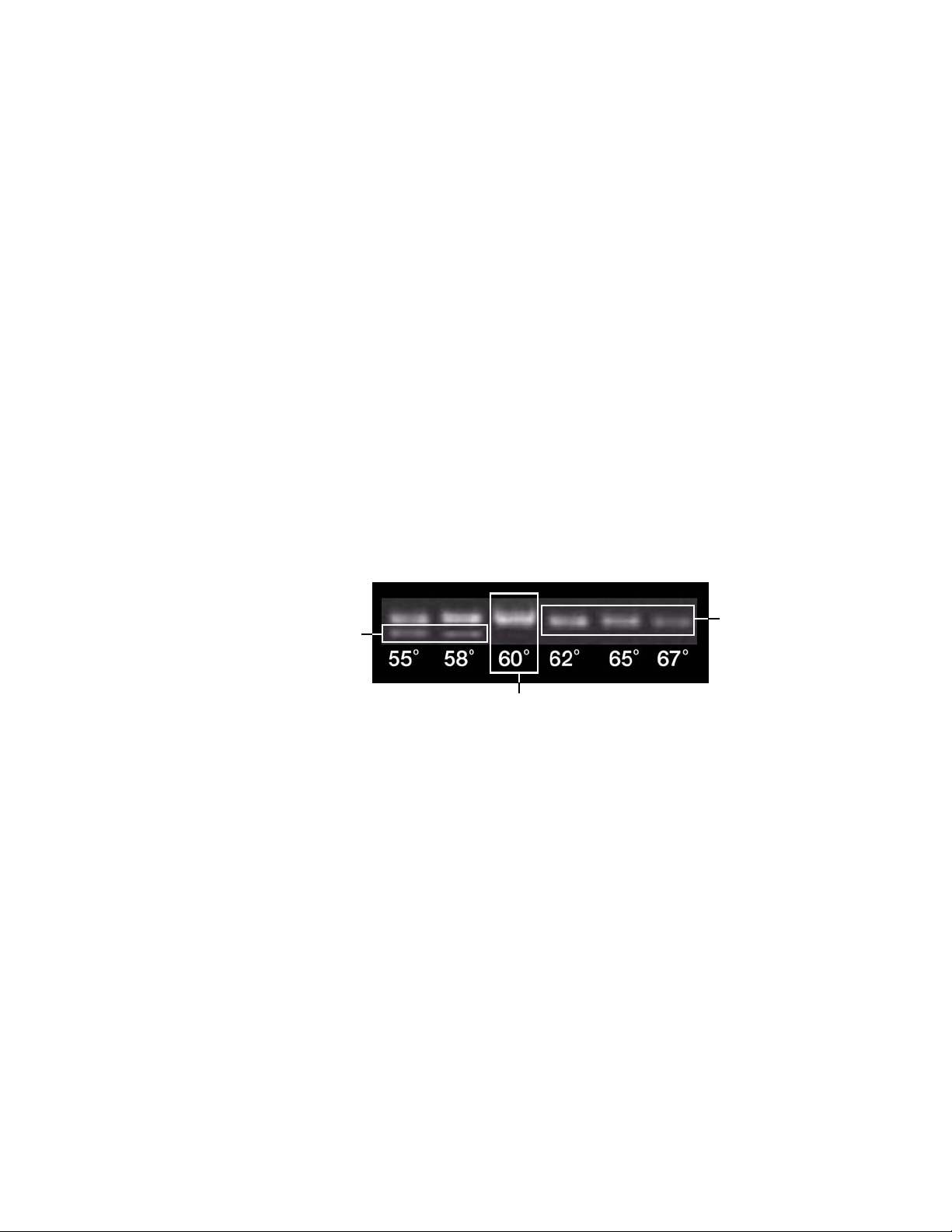
S1000 Thermal Cycler Manual
Optimizing Annealing Temperature Steps with a Gradient
Optimizing the annealing step is critical for an efficient reaction that yields a clean product.
Use a gradient to optimize the temperature of the annealing step. In addition, you can use a
gradient step to optimize other temperature steps.
Follow these steps as a suggested approach to optimizing the annealing temperature:
1. Calculate the predicted annealing temperature based on the melting temperature (T
the primers and template.
When the S1000 thermal cycler is connected to a C1000 thermal cycler, use the T
calculator available on the C1000 cycler to find the T
template.
2. Create a PCR protocol with a gradient step in the annealing step.
Choose a gradient range that is as wide as possible to test for the optimal annealing
temperature, and bracket the calculated T
by 5–12°C. For example, if the calculated Ta
a
is 55°C, then use a 24°C gradient to bracket that T
NOTE: The widest possible gradient on the S1000 thermal cycler is 24°C.
3. Choose a high annealing temperature from the results of the gradient PCR run to reduce
the chance of nonspecific primer binding. See step 2, above, for details on creating a
gradient. In Figure 82, the gradient range is 55–67°C, and the best annealing occurs at
60°C.
of any combination of primers and
m
.
a
) of
m
a
Temperature too low:
nonspecific bands
too high:
faint bands
Good temperature:
solid band and no nonspecific bands
Figure 82. The effect on annealing temperature on the outcome of a PCR run.
As a starting point, use the highest annealing temperature and subtract 1 or 2°C. Do not
use the absolute highest temperature. At higher temperatures, the yield decreases and
results in faint bands. Furthermore, at high temperatures, the primers might behave
inconsistently from one PCR run to another.
4. (Optional) Run a narrower annealing temperature gradient using the results from the first,
wider temperature gradient. Bracket the annealing temperature chosen in step 3 (above)
Temperature
o
by 5
C. Choose the final annealing temperature from the highest successful temperature
in the results of this gradient.
For example, if the highest successful annealing temperature in step 3 is 60°C, then
bracket that temperature with a narrower gradient (±5°C). In this example, the narrow
gradient is 55–65°C. Choose the final annealing temperature from a high successful
temperature in the gradient experiment as described in step 3 above.
49
Page 59

Optimizing PCR With Small Sample Volumes
Optimizing PCR With Small Sample Volumes
Running a PCR protocol with a small sample volume requires optimization to prevent
evaporation and condensation. Follow these suggestions for optimizing PCR with a reaction
volume below 10 µl:
• Control evaporation with a wax seal
A wax, such as Chill-out™ liquid wax, is the best seal for reducing evaporation. Further
reduction is possible by using a second seal, such as a cap or film.
• Reoptimize the annealing temperature to prevent nonspecific priming and increase
target amplification
When running an established protocol with a smaller sample volume (<10 µl), the
annealing temperature may need to be reoptimized. If mispriming or low amplification is
observed (and reagent problems have been ruled out), adjust the protocol by optimizing
the annealing temperature step using a gradient as described on page 49.
• Lower the lid temperature to reduce sample loss due to evaporation
The heated lid prevents condensation from forming in the microplate or tube, which is
critical when the sample volume is small. However, using the same lid temperature with
a smaller sample volume can increase evaporation. To prevent evaporation, lower the lid
temperature and test the reaction for condensation.
• Run the reaction in a 384-well reaction module
The 384-well block is optimized for small sample volumes and is the best block for this
application.
Transferring Protocols from Another Thermal Cycler
To achieve the same results after transferring a PCR protocol to the S1000 thermal cycler from
another thermal cycler, the ramp rate may need to be lowered. If identical reactions that are
run on a thermal cycler with a slower ramp rate provide the same data, change the ramp rate
on the S1000 thermal cycler.
When transferring a protocol to the S1000 thermal cycler, follow these guidelines:
• Match the ramp rate of the other thermal cycler by changing the rate in each relevant
step on the S1000 thermal cycler. (See “Changing the Ramp Rate in a Temperature
Step” on page 21.) In general, the ramp rate for the annealing step could be lowered
when a protocol from a thermal cycler with a slower ramp rate is moved to the S1000
thermal cycler
• Increase the amount of Mg
conditions have changed. Adding Mg
cause some secondary PCR products
• Adjust the temperature in each step to reoptimize the protocol and the annealing
temperature. (See “Optimizing Annealing Temperature Steps with a Gradient” on
page 49)
++
in the reagents to help the primers anneal when the
++
increases the primary product, but may also
Troubleshooting PCR Problems
This section provides a quick guide for PCR troubleshooting options. For more detailed and
extensive troubleshooting, go to the Gene Expression Gateway (www.bio-rad.com/genomics/)
and select Support > Amplification Central > PCR Doctor
50
Page 60

S1000 Thermal Cycler Manual
Use the following suggestions to adjust and reoptimize a reaction that has failed due to the
presence of:
• Nonspecific PCR products, in addition to the target product
Nonspecific products result from mispriming. If reagent problems have been ruled out,
increase the annealing temperature to increase specificity of primer binding. To find the
optimal annealing temperature, use a gradient.
• Nonspecific PCR products without the target product
Nonspecific product with no target production is a result of complete mispriming. If
reagent problems have been ruled out, adjust the hold time in the annealing and
extension steps to increase specificity of primer binding. Increasing the hold time also
provides more time for complete extension.
• Low yield of the target PCR product
Low PCR yield is a result of mispriming, an overly short extension hold time, or too high
an annealing temperature. When the low yield is not a result of reagent problems, adjust
the protocol.
Run a touchdown protocol (page 72) to increase amplification of the target product.
Alternatively, decrease the annealing temperature or run a gradient to optimize the
annealing temperature. (See “Optimizing Annealing Temperature Steps with a Gradient”
on page 49).
Selecting Compatible Reaction Vessels and Sealing Options
The composition and thickness of reaction vessels influence the outcome of a reaction.
Microplates, tubes, sealers, and caps come in a variety of compositions and colors. Bio-Rad
tests the standard supplies for compatibility with the 1000-series thermal cyclers.
Refer to Table 21 on page 78 for a full list of available microplates, tubes, and sealing options
that are compatible with 1000-series thermal cyclers. Catalog numbers for these consumables
are provided for easy ordering.
Whenever the source or composition of vessels is changed, it is good practice to reoptimize
the protocol before running an important experiment.
NOTE: Sealing wax, such as Chill-out liquid wax, is specifically recommended to
seal small sample volumes of less than 10 µl. Wax solidifies at room temperature.
Pierce the solid wax with a micropipet tip to remove the sample. For more
information about optimizing protocols for small sample volumes, see “Optimizing
PCR With Small Sample Volumes” on page 50.
For a full list of available reagents and supplies, refer to the Life Science Research Product
catalog or online at discover.bio-rad.com.
51
Page 61

Selecting Compatible Reaction Vessels and Sealing Options
52
Page 62

S1000 Thermal Cycler Manual
6 Advanced Tools and Functions
Read this chapter for information on advanced tools and functions on the S1000 thermal
cycler.
• TOOLS options (below)
• Controlling S1000 thermal cyclers with a C1000 thermal cycler (page 61)
TOOLS Options
To see the list of instrument settings and tools:
1. Select TOOLS from the main menu. The following functions are available in the TOOLS
option:
• LAST RUN
• SELF TEST — to run a self test on the thermal cycler (page 54)
• VERSION — to view the current instrument firmware version (page 55)
• NAME — to enter a name for the thermal cycler (page 56)
• DEFAULTS — to change default lid temperature, “turn off below” feature, and
sample volume (page 57)
• GRADCALC — to view a temperature gradient based on user defined parameters
(page 58)
• CONTRAST — to change the instrument’s LCD contrast (page 59)
• PORT —
(page 60)
2. To return to the main menu, press ENTER.
LAST RUN Screen
To see a summary of the last protocol that was run on the S1000 thermal cycler:
1. Select TOOLS in the main menu. Press ENTER to confirm the selection.
— to view the last protocol that was run (page 53)
to change the port used to control the S1000 thermal cycler remotely
53
Page 63
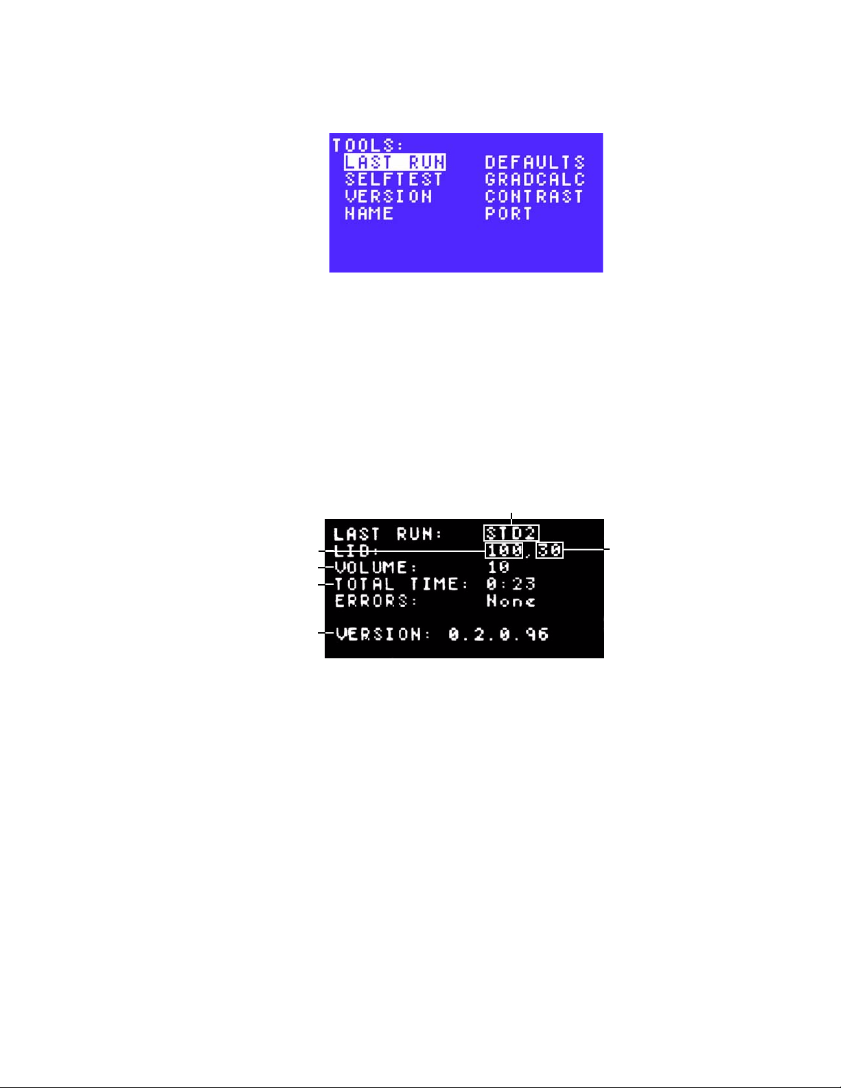
TOOLS Options
2. Select LAST RUN using the arrow keys (Figure 83), and press ENTER to confirm the
3. The LAST RUN screen is displayed (Figure 84). This screen shows a synopsis of the
selection.
Figure 83. Select LAST RUN for a summary of the last protocol run on the cycler.
NOTE: For dual 48/48 reaction modules, the LAST RUN tool toggles to show the
last protocol that was run on each block.
parameters in the last protocol that was run, including:
• Protocol name
• Lid temperature during the run
• Turn off below temperature for the lid during the run
• Sample volume, which determines the temperature control mode during
• Total run time
• Number of errors detected during the run
• Firmware version on the S1000 thermal cycler during the run
Protocol name
Turn off below
Lid temperature
Sample volume
Total run time
Firmware version
Figure 84. The LAST RUN screen.
4. Press ENTER to return to the TOOLS option.
temperature
Testing the Instrument
The S1000 thermal cycler automatically runs a self test every time it starts a run to check that
it is running within specification.
To manually run a self test:
1. Select TOOLS in the main menu. Press ENTER to confirm the selection.
54
Page 64

S1000 Thermal Cycler Manual
2. Select SELFTEST (Figure 85), and press ENTER to continue to the next screen.
Figure 85. Select SELFTEST to manually run a self test.
3. The thermal cycler displays the self testing screen while it runs the test (Figure 86). When
the test is successfully completed, the main menu is displayed.
NOTE: The instrument fans turn on and off during the test.
Figure 86. The self testing screen.
Checking the Firmware Version
To check the firmware version that is currently on the thermal cycler:
1. Select TOOLS in the main menu. Press ENTER to confirm the selection.
2. Select VERSION (Figure 87), and press ENTER to continue to the next screen.
Figure 87. Select VERSION from the TOOLS option.
3. The firmware version is displayed on the screen (Figure 88). The header version
(HEADER) of the reaction module is displayed, which means the firmware expects at
least the specified version.
55
Page 65

TOOLS Options
4. Press ENTER to return to the main menu
Naming the Thermal Cycler
To name or rename the thermal cycler:
1. Select NAME using the arrow keys (Figure 89), then press ENTER.
Figure 88. The firmware and header versions are displayed.
The S1000 thermal cycler name is displayed on the main menu.
Figure 89. Select NAME to enter a new thermal cycler name.
2. Enter the new thermal cycler name by pressing the up and down arrow keys to select a
letter and the numeric keys to type a number (Figure 90). Press ENTER to accept the
selection and continue to the next character in the name.
NOTE: A cycler name can contain 1–8 characters. The characters can be numbers
or capital letters.
Figure 90. Enter the new thermal cycler name one character at a time.
NOTE: The name identifies the S1000 thermal cycler when it is controlled by the
C1000 thermal cycler. The thermal cycler name appears in the C1000 thermal
cycler instrument tree or in the C1000 Manager software Detected Instruments
panel on the left side of the screen. If the S1000 thermal cycler is not named, then
the S1000 thermal cycler serial number is used.
56
Page 66

S1000 Thermal Cycler Manual
3. Press ENTER to confirm the thermal cycler name (Figure 91) and return to the main
menu.
Figure 91. Press ENTER once the thermal cycler name is entered.
Changing the Default Parameters
The following three default parameters can be modified when running a protocol or incubating
samples:
• Lid Target — sets the default lid temperature for a new protocol. The default
temperature is set at 105°C for 96- or dual 48-well reaction blocks and 95°C for
384-well blocks. The new lid temperature can be 0–110°C
• Turn off below — when the block is running an infinite hold at a temperature
below the Turn off below parameter, the lid heater is maintained at 31°C
• Sample Vol — sets the default sample volume in a new protocol (see ep 4 on
page 13). The sample volume range can be 0–50 µl (or 0–30 µl when using the
384-well reaction modules) and the default parameter is 10 µl. See page 3 for the
recommended reaction volume
To view or change the default parameters on the S1000 thermal cycler:
1. Select DEFAULTS using the arrow keys (Figure 92). Press ENTER to continue to the
next screen.
Figure 92. Select DEFAULTS to change the default parameters on the thermal cycler.
2. Press the up and down arrow keys to select the default setting to be modified.
Figure 93 shows the default parameters for the S1000 thermal cycler.
Figure 93. The default parameters for the S1000 thermal cycler.
57
Page 67

TOOLS Options
3. Use the numeric keys to enter the new parameter. Press ENTER to confirm the number
4. To save the parameters, select YES and press ENTER. To reject changes and return to
Viewing a Temperature Gradient
In the S1000 thermal cycler, the temperature gradient is distributed from the front (row H;
coolest temperatures) to the back (row A; hottest temperatures) of the block.
To review a temperature gradient to determine the temperature in each row of the block:
1. Select TOOLS from the main menu.
2. Select GRADCALC using the arrow keys (Figure 94), and press ENTER to continue to
and move to the next parameter to be modified.
the main menu, use the right arrow key to select No and press ENTER.
the next screen.
Figure 94. Select GRADCALC to view the temperature in each row of the block.
3. Enter the lower temperature in the gradient using the numeric keys. The limit is 30.0–
99.0°C. Press CANCEL (
In Figure 95, the lower temperature is 65°C.
Lower temperature
in gradient
Figure 95. Enter the lower temperature in the gradient.
4. Enter the upper temperature in the gradient using the numeric keys. Press CANCEL (
enter a decimal point. The upper temperature must be greater than the lower
temperature, and must be within 24.0°C of the lower temperature.
.
) to enter a decimal point.
Limits for lower
temperature
.
) to
58
Page 68

In Figure 96, the upper temperature is 75°C.
S1000 Thermal Cycler Manual
Upper temperature
in gradient
Figure 96. Enter the upper temperature in the gradient.
5. The temperature gradient is displayed in each row of wells in the block.
In Figure 97, the temperature in row D of this 96-well block is 71.4°C.
Rows in 96-well
block (A–H)
Figure 97. The temperature gradient is displayed in each row of wells in the block.
NOTE: The temperature in the middle rows is estimated. The estimate is based on
the temperatures in the front and back rows and on the number of rows in the
block.
Limit for upper
temperature
Temperature
in row D
Changing the Screen View
To change the contrast of the LCD and improve the visibility of characters displayed on the
screens, use the following instructions:
1. Select TOOLS from the main menu.
2. Select CONTRAST using the arrow keys (Figure 98), and press ENTER to continue to
the next screen.
Figure 98. Select CONTRAST to change the contrast of the LCD.
3. Adjust the contrast using the right and left arrow keys.
NOTE: Press the left arrow key to decrease (–) the contrast and the right arrow key
to increase (+) the contrast.
59
Page 69

TOOLS Options
4. To accept the changes and return to the TOOLS options, press ENTER. To reject the
Setting Up the S1000 Cycler For Remote Control
To set up the S1000 thermal cycler for remote control:
1. Select TOOLS to instruct the thermal cycler to list the data transfer ports.
2. Select PORT (Figure 100) and press ENTER to continue to the next screen.
In Figure 99, the contrast is increased.
Figure 99. Increase the contrast using the right arrow key.
changes and return to the original contrast, press CANCEL.
Figure 100. Select PORT to set up the S1000 thermal cycler for remote control.
3. Select a port from the list of all ports on the thermal cycler (Figure 101), and press
ENTER to return to the TOOLS option.
Figure 101. Select a port from the list of all ports on the thermal cycler.
60
Page 70

S1000 Thermal Cycler Manual
Controlling S1000 Thermal Cyclers with a C1000 Thermal Cycler
The S1000 thermal cycler can be run in stand-alone single instrument, stand-alone multiinstrument, or software-controlled multi-instrument configuration. In stand-alone multiinstrument configuration, up to three S1000 thermal cyclers can be run under the control of a
C1000 thermal cycler. Each S1000 thermal cycler can be connected to the C1000 thermal
cycler through the USB A port of the C1000 thermal cycler.
When connected to a C1000 thermal cycler, the S1000 thermal cyclers can be controlled by
either the control panel on the C1000 thermal cycler or the C1000 Manager software.
Connecting S1000 Cyclers Directly to a C1000 Cycler
To connect up to three S1000 thermal cyclers directly to a C1000 thermal cycler, follow these
instructions:
1. Plug a high quality, shielded USB cable into the USB B port on the back of the S1000
thermal cycler.
For the USB cable part number, see “Accessories for the 1000-Series Thermal Cyclers”
on page 78.
2. Plug the other side of the USB cable into a USB A port on the back of the C1000 thermal
cycler.
The C1000 thermal cycler instrument detects the attached S1000 thermal cycler.
3. Repeat steps 1 and 2 to connect up to three S1000 cyclers directly to the same C1000
thermal cycler.
4. Open the MAIN screen or instrument tree on the C1000 thermal cycler, or in the C1000
Manager software if the C1000 thermal cycler is connected to a computer.
5. Select the S1000 thermal cycler by serial number or name.
NOTE: If the S1000 thermal cycler instrument has a name, then the name is
displayed instead of the serial number.
Operating the S1000 Thermal Cycler While Under the
Control of the C1000 Cycler
When the S1000 thermal cycler is under the control of the C1000 thermal cycler, it is in “semilock down mode”. In this mode, the S1000 thermal cycler does not respond when control
panel keys are pressed. However, the following keys function on the control panel:
• SCREEN — to access the running, graphical, and time remaining screens
• PAUSE — to temporarily stop a protocol that is currently running on the S1000
thermal cycler. This function is active when an individual protocol screen is being
displayed
• CANCEL — to cancel a protocol that is currently running on the S1000 thermal
cycler. This function is active when an individual protocol screen is being displayed
• ENTER — to begin a run that has been remotely sent from the C1000 Manager
software
• ENTER — to skip a step. This function is active when an individual protocol screen
is being displayed
61
Page 71

Controlling S1000 Thermal Cyclers with a C1000 Thermal Cycler
Controlling Thermal Cyclers Using the C1000 Manager
Software
In a software-controlled multi-instrument configuration, the C1000 Manager software controls
up to 32, 1000-series cyclers at once from a single computer. Protocols can be run on
individual or multiple blocks, either independently or simultaneously.
NOTE: In a software-controlled configuration, the S1000 thermal cycler is not
directly controlled by the C1000 Manager software. The S1000 thermal cycler must
first be connected to a C1000 thermal cycler that is attached to a PC computer
running the C1000 Manager software. See “Connecting S1000 Cyclers Directly to a
C1000 Cycler” on page 61.
For detailed instructions on using the C1000 Manager software to control S1000 thermal
cyclers, see the C1000 thermal cycler instruction manual.
62
Page 72

S1000 Thermal Cycler Manual
7 Maintenance and
Troubleshooting
Read this chapter for information on maintaining the S1000 thermal cycler and troubleshooting
problems on the thermal cycler.
• Cleaning and maintaining the S1000 thermal cycler (below)
• Maintaining sufficient air flow (page 65)
• Troubleshooting error messages on the S1000 thermal cycler (page 66)
Cleaning and Maintaining the S1000 Thermal Cycler
The S1000 thermal cycler requires little maintenance for proper operation and precise thermal
control. However, with long and constant use, the thermal cycler requires some cleaning and
other maintenance. Information on cleaning the thermal cycler base and reaction module is
included in this chapter. In addition, instructions on replacing the fuses are provided.
TIP: For robotic installations where many instruments run constantly, perform a
regular check for dust, spills, and debris that could interfere with optimal
instrument performance.
Cleaning the S1000 Thermal Cycler
The S1000 thermal cycler should be cleaned on a regular schedule to remove any debris or
dirt that might interfere with proper function. Clean the base to prevent damage to the air
intake or reaction module bay.
NOTE: For instructions on handling and cleaning radioactive or biohazardous
materials, consult the guidelines for radiation safety and biosafety provided by your
institution. These guidelines include cleaning, monitoring, and disposal methods
for hazardous materials.
To clean the thermal cycler base, follow the instructions below, paying careful attention to the
warnings:
WARNING! To prevent electrical shock, always turn off and unplug the instrument
before cleaning it.
• Clean the air vents. Remove dust with a soft brush, damp cloth, or vacuum cleaner.
Remove any heavy dust that is deep in the vents with a vacuum cleaner. Cleaning the
vents allows sufficient air flow for precise thermal control during a run
63
Page 73

Cleaning and Maintaining the S1000 Thermal Cycler
• Clean the control panel. Remove debris on the control panel with a soft cloth and mild
soap solution. Cleaning the panel prevents debris that may obscure the display
WARNING! Do not use abrasive detergents or rough material since they scratch
the control panel.
• Clean the reaction module bay. Clean with a damp soft cloth to remove debris and
spilled liquids. Cleaning the bay allows precise heating and cooling of the reaction block
WARNING! Never use cleaning solutions that are corrosive to aluminium. Avoid
scratching the surface of the bay, which interferes with precise thermal control.
WARNING! Never pour water or other solutions in the reaction module bay. Wet
components can cause electrical shock when the thermal cycler is plugged in.
• Clean the outside case of the thermal cycler base. Use a damp cloth or tissue to
clean spills off the outside case. If needed, use a mild soap solution and remove the
residue completely. Cleaning the outside case prevents corrosion
Cleaning the Reaction Modules
Clean the reaction modules of the S1000 thermal cycler on a regular schedule to prevent
reagents from accumulating and interfering with the ability of the reaction block to change
temperature quickly.
To clean the reaction module, follow these instructions, paying careful attention to the
warnings:
WARNING! To prevent electrical shock, always remove the reaction module from
the thermal cycler base before cleaning it.
• Clean the cooling fins. Remove dust from the cooling fins with a soft brush or damp
cloth. Remove any heavy dust that is deep in the fins with a vacuum cleaner. Use water
and a soft cloth to remove debris that is stuck to the fins. Avoid scratching the surface.
Never use cleaning solutions that are corrosive to aluminum, such as bleach or abrasive
cleansers. If needed, use a mild soap solution and rinse well to remove the residue
completely. Cleaning the fins improves precise sample heating and cooling
• Clean the outside cover of the reaction block. Use a soft cloth and water to
remove debris from the outer block
WARNING! Never clean the block with strong alkaline solutions (strong soap,
ammonia, or high-concentration bleach). Never use corrosive or abrasive cleaning
solutions. These cleaning agents can damage the block and prevent precise
thermal control.
• Clean the block wells. Clean spills immediately to prevent them from drying inside
wells. Use disposable plastic pipets with water (recommended), 95% ethanol, or a 1:100
dilution of bleach in water. Always rinse the wells with water several times to remove all
traces of ethanol, bleach, or soap
WARNING! If left in the block wells, bleach, ethanol, or soap could corrode the
block and/or destroy tubes and microplates during a run. Always rinse the block
well after cleaning it with any solution other than water.
• If oil is used, the wells must be cleaned thoroughly and often. Use of oil in the
wells is not recommended. Clean the oil when it is discolored or contains dirt. Use a
solution of 95% ethanol to clean oil. Do not allow oil to build up in the block
WARNING! Never heat the block after adding a cleaning solution. Heating the
block with cleaning solution damages the block, lid, and thermal cycler base.
• Clean the inner of the reaction module. Use a soft cloth and water to remove debris
and solutions from the inner lid surface. Never use abrasive detergents or rough material
64
Page 74

that scratch the surface. Cleaning the inner lid improves precise sample heating and
cooling
• Clean the outer lid surface of the reaction module. Use a damp cloth or tissue to
clean spills off the outside case. If needed, use a mild soap solution and rinse the surface
with a damp cloth. Cleaning the cover prevents corrosion
Maintaining Sufficient Air Flow
The S1000 thermal cycler requires sufficient air flow to precisely heat and cool to the correct
target temperature. If the flow of air is blocked the thermal cycler cannot ramp to the correct
temperature in the specified time. This section includes instructions for testing the air flow and
provides suggestions for fixing low or warm air flow.
Testing for Sufficient Air Flow
The air flow is sufficient when the thermal cycler heats and cools to the correct target
temperatures promptly. When the S1000 thermal cycler is first set up in a new location, use
the following steps to determine the presence of sufficient air flow:
1. Set up the instrument in the location where it is going to be used, then turn the power on.
S1000 Thermal Cycler Manual
2. Adjust the local environment for typical conditions.
Turn on any nearby equipment, such as fans. Also open any window blinds to reproduce
typical conditions during a run. If more than one thermal cycler is in the area, run a
protocol on all the thermal cyclers at the same time.
3. Run a typical PCR protocol for 30 min.
To run a protocol, samples are not required; however, an empty microplate or tubes
should be included. The lid does not heat correctly if it touches the hot block of the
reaction module.
4. Measure the air temperature at the air intake vents of all the thermal cyclers.
If the air intake temperature increases above 31°C, see “Fixing Insufficient Air Flow” to
ensure sufficient air flow.
Fixing Insufficient Air Flow
If the air temperature near the thermal cycler is above 31°C, make one or more of the following
changes to increase the flow of cooler air around the thermal cycler:
• Adjust air conditioning to lower the ambient air temperature
• Move the thermal cycler to another location
• Provide more space around the S1000 thermal cycler and between adjacent
instruments. Arrange instruments so that the warm exhaust air from one instrument
does not enter the air intake vents of another
• Shield the thermal cycler from heat sources, such as radiators, other heat-producing
instruments, and bright sunlight
65
Page 75
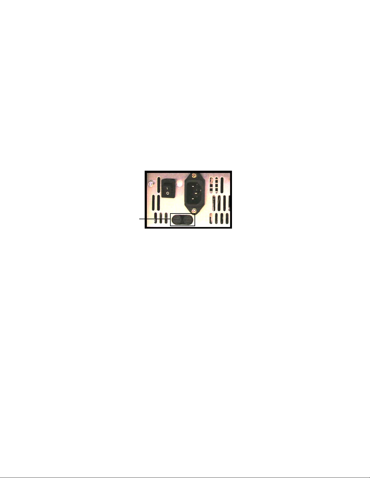
Troubleshooting Error Messages on the S1000 Cycler
Replacing Fuses
Fuses on the S1000 thermal cycler are designed to blow in case of severe power surges or
other causes of electrical short. This process protects both the user and the instrument from
excessive electric charge. Fuses on the S1000 thermal cycler rarely need to be replaced.
However, some institutions prefer to replace fuses on a regular basis to maintain uninterrupted
operation.
If the thermal cycler does not turn on, first check that the power cord is plugged in to a
functioning power source. Also, check that the power cord and power source are within the
specifications for this instrument. To replace the power cord, contact Bio-Rad Technical
Support. For contact information, see “Bio-Rad Laboratories Resources” on page iii.
Finally, check that the fuses are intact. The S1000 thermal cycler runs with two fuses
(Figure 102). To remove and check the fuses, follow these steps:
WARNING! To prevent electrical shock, always turn off and unplug the instrument
from an electrical outlet before checking the fuses.
1. Use a small coin to unscrew the fuse drawer.
Fuse drawer
Figure 102. The fuse drawer on the back of the S1000 thermal cycler.
2. Pull out the fuse drawer and remove each fuse.
3. If a fuse is damaged, replace it with the correct fuse, and close the drawer.
A bad fuse shows a break or burned spot in the metal. A good fuse has intact metal.
Troubleshooting Error Messages on the S1000 Cycler
In general, when the S1000 thermal cycler displays a warning or error message, the
instructions for fixing the problem are contained in the message.
66
Page 76

S1000 Thermal Cycler Manual
Warning and Error Messages
A warning or error message is displayed when external power fails during a run (Figure 103).
This error message displays what protocol was running, when the protocol stopped due to the
power failure, and the block temperature when the thermal cycler resumed the run.
Figure 103. An error message alerting that the protocol was interrupted.
NOTE: A power failure can change the outcome of a PCR run. The hold time for the
step that was running when the power failed is lengthened, causing the sample to
deviate from the target temperature until the power resumes
The S1000 thermal cycler tracks errors that occur during a run. After a run, all messages are
displayed. For example, when a run is cancelled, the PROTOCOL CANCELLED screen is
displayed as shown in Figure 104.
Figure 104. The PROTOCOL CANCELLED screen.
To clear a message or error and continue to the next screen, press ENTER. When all
messages are cleared, the S1000 thermal cycler returns to the main menu.
The total number of error messages that occur during a run is displayed on the LAST RUN
screen (page 53). However, there is no process in the S1000 thermal cycler to open these error
messages after they are closed at the end of a run. If you want to track and log error
messages, run the S1000 thermal cycler under the control of a C1000 or a robotic system that
can retrieve a list of errors in the system and run logs.
Error messages are recorded in the Run Logs as listed in Table 12.
TIP: The S1000 thermal cycler also tracks errors and system messages for all
attached S1000 thermal cycler thermal cycler.
67
Page 77

Troubleshooting Error Messages on the S1000 Cycler
several error messages indicate problems that can be resolved or that might not change the
results of your PCR. The table below contains a list of error messages and possible solutions:]
Table 12. Warning and error message solutions
Message Cause
A/C POWER FAILED
POWER OUTAGE DURING
CYCLE X STEP Y
RESTARTED AT ZZ.Z
TO CONTINUE
PRESS ENTER
PLEASE RESTART CYCLER
PLEASE CALL BIO-RAD FOR SERVICE
BLOCK OVERHEATED
PLEASE RESTART CYCLER
HEATSINK OVERHEATED
PLEASE CALL
BIO-RAD FOR SERVICE
Displayed when a machine running a
protocol has been turned off, either
intentionally or due to a power outage,
and then turned on again.
Reaction module has exceeded
maximum temperature of 107.5°C or
sensor has a malfunction and is not
measuring temperature accurately.
Protocol terminated.
Heatsink temperature has exceeded
75°C. Protocol terminated.
PLEASE RESTART CYCLER
SYSTEM OVERHEATED
PLEASE CALL
BIO-RAD FOR SERVICE
PLEASE CALL
BIO-RAD FOR SERVICE
ALL BLOCK SENSORS FAILED
PLEASE CALL
BIO-RAD FOR SERVICE
POWER SUPPLY
OVERHEATED
PLEASE CALL
BIO-RAD FOR SERVICE
HEATED LID FAILED
PROTOCOL CANCELLED
PLEASE CHECK AIRFLOW
HTSINK OVERHEATING
PLEASE CALL BIO-RAD FOR SERVICE
PLEASE CHECK AIRFLOW
SYSTEM OVERHEATING
PLEASE CALL BIO-RAD FOR SERVICE
PLEASE CHECK AIRFLOW
PS OVERHEATING
PLEASE CALL BIO-RAD FOR SERVICE
PLEASE CALL BIO-RAD FOR SERVICE
SLOW BLOCK CYCLING
Amplifier 1 temperature has exceeded
85°C. Protocol terminated.
All block sensors have failed (see below
for failure criteria). Protocol terminated.
Power Supply temperature has exceeded
85°C. Protocol terminated.
Lid sensor has failed during lid preheat.
Protocol terminated.
Heatsink has exceeded 70°C. System
beeps and displays error.
Amp temp has exceeded 80°C. System
beeps and displays error.
Power Supply temperature has exceeded
80°C. System beeps and displays error.
Block failed to achieve target in the
estimated time.
68
PLEASE CALL BIO-RAD FOR SERVICE
SLOW LID CYCLING
Lid failed to achieve target in the
estimated time.
Page 78

Table 12. Warning and error message solutions
Message Cause
S1000 Thermal Cycler Manual
PLEASE CALL BIO-RAD FOR SERVICE
SLOW GRADIENT
PLEASE CALL BIO-RAD FOR SERVICE
HEATED LID FAILED
PLEASE CALL BIO-RAD FOR SERVICE
BLOCK SENSOR 0
FAILED
PLEASE CALL BIO-RAD FOR SERVICE
BLOCK SENSOR 1
FAILED
PLEASE CALL BIO-RAD FOR SERVICE
BLOCK SENSOR 2
FAILED
PLEASE CALL BIO-RAD FOR SERVICE
BLOCK SENSOR 3
FAILED
PLEASE CALL BIO-RAD FOR SERVICE
BLOCK SENSOR 4
FAILED
PLEASE CALL BIO-RAD FOR SERVICE
BLOCK SENSOR 5
FAILED
PLEASE CALL BIO-RAD FOR SERVICE
LEFT LID SENSOR
FAILED
Block failed to achieve gradient in the
estimated time.
(singles only) If the right and left lid heater
channels deviate from each other by
more than 5°C the lid is shut off.
Block sensor 0 has failed* and the
protocol was terminated.
Block sensor 1 has failed* and the
protocol was terminated.
Block sensor 2 has failed* and the
protocol was terminated.
Block sensor 3 has failed* and the
protocol was terminated.
Block sensor 4 has failed* and the
protocol was terminated.
Block sensor 5 has failed* and the
protocol was terminated.
Left lid sensor has failed*. If a dual,
protocol terminated. If a single and
BOTH lid sensors failed, protocol
terminated and block sent to 4°C.
PLEASE CALL BIO-RAD FOR SERVICE
RIGHT LID SENSOR
FAILED
PLEASE CALL BIO-RAD FOR SERVICE
LEFT HEATSINK SENSOR
FAILED
PLEASE CALL BIO-RAD FOR SERVICE
RIGHT HEATSINK SENSOR
FAILED
PLEASE CALL BIO-RAD FOR SERVICE
LID OVERHEATED
AND WAS SHUT OFF
PLEASE CALL BIO-RAD FOR SERVICE
AMP1 TEMP SENSOR
FAILED
Right lid sensor has failed*. If a dual,
protocol terminated. If a single and
BOTH lid sensors failed, protocol
terminated and block sent to 4°C.
Left heatsink sensor has failed*, system
using average of amplifier temperatures
to continue.
Right heatsink sensor has failed* system
using average of amplifier temperatures
to continue.
(duals only) Lid has overheated and has
been shut off and protocol has been
terminated.
Amplifier temperature sensor 1 has
failed*.
69
Page 79

Troubleshooting Error Messages on the S1000 Cycler
Table 12. Warning and error message solutions
Message Cause
PLEASE CALL BIO-RAD FOR SERVICE
POWER SUPPLY SENSOR
FAILED
PLEASE CALL BIO-RAD FOR SERVICE
BLOCK POWER FAILURE
PROTOCOL CANCELLED
PLEASE CALL BIO-RAD FOR SERVICE
LOGIC POWER FAILURE
PLEASE CALL BIO-RAD FOR SERVICE
BASE POWER FAILURE
PROTOCOL CANCELLED
PLEASE CALL BIO-RAD FOR SERVICE
AMP2 TEMP SENSOR
FAILED
BLOCK MISSING
PROTOCOL CANCELLED
PLEASE CALL BIO-RAD FOR SERVICE
PLEASE CALL BIO-RAD FOR SERVICE
MEMORY CORRUPT
PROTOCOLS MAY BE LOST
PLEASE RESTART CYCLER
BAD REACTION MODULE
PLEASE CALL BIO-RAD FOR SERVICE
PLEASE RESTART CYCLER
INCORRECT CHECKSUM
PLEASE CALL BIO-RAD FOR SERVICE
Power Supply sensor has failed*.
Power to block is out of range.
Logic power sensor is out of bounds.
Base power sensor is out of bounds.
Protocol cancelled.
Amplifier temperature sensor 2 has
failed*.
Reaction module has been removed.
Protocol terminated.
Protocol storage memory has been
corrupted.
Unable to read information from reaction
module properly.
Information read from reaction module
appears incorrect.
70
PLEASE RESTART CYCLER
BLOCK POWER SHUT OFF
PLEASE CALL BIO-RAD FOR SERVICE
PROTOCOL CANCELLED
SAMPLES COOLED AT 4C
BLOCK SENSOR FAILED
AT CYCLE X, STEP Y
PLEASE RESTART CYCLER
PLEASE CALL BIO-RAD
The error message may instruct the user to contact Bio-Rad. In this event, call the nearest
Bio-Rad Laboratories Technical Support team (see “Bio-Rad Laboratories Resources” on
page iii for more detail).
*Sensor Failure means that the sensor was deemed short, open or had changed more than
3°C in a 50 msec period and that this condition was present for more than 2 sec.
If two or more block sensors fail (or both lid sensors fail), the protocol is terminated and the
block is sent to 4°C to preserve samples.
There was a problem with the block and
power was shut off
One of the block sensors in a single block
has failed. The system has cancelled the
protocol at step x, cycle y and sent the
block to 4°C to preserve the samples.
Page 80

S1000 Thermal Cycler Manual
Appendix A: Preinstalled Protocols
Standard Protocols
The S1000 thermal cycler is packaged with two standard protocols that run two-step and
three-step PCR with a standard DNA polymerase. Use these protocols to begin running PCR
with new primers and DNA template, or copy them to begin writing a new protocol. Table 13
lists the parameters in each standard protocol.
Table 13. Standard protocols
Step
1
2
3
4
5
6
7
8
STD2 STD3
Standard Two-Step Protocol Standard Three-Step Protocol
Target
Temperature (°C)
or GOTO Step
95 3:00 95 3:00
95 0:30 95 0:30
65 0:30 55 0:30
GOTO 2 29x 72 0:30
72 7:00 GOTO 2 29x
12 Infinite hold ∝ 72 1:00
END 12 Infinite hold ∝
Time (min:sec)
or Repeats
Target
Temperature (°C)
or GOTO Step
END
Time (min:sec)
or Repeats
71
Page 81

Touchdown Protocol
Touchdown Protocol
A touchdown protocol tests for the best annealing temperature for a specific primer-template
pair. Choose this protocol to test a new set of primers and DNA template for the optimal
annealing temperature. Table 14 lists the parameters of the preinstalled touchdown protocol.
Table 14. Touchdown protocol
TCHDOWN
To Identify the Optimal Annealing Temperature
Step
1
2
3
4
5
6
7
8
9
10
11
12
Target Temperature (°C)
or GOTO Step
95 3:00
95 0:30
60 (increment at –0.5°C/
cycle)
72 0:30
GOTO 2 29x
95 0:30
45 0:30
72 0:30
GOTO 6 29x
72 7:00
12 Infinite hold ∝
END
Time (min:sec) or Repeats
0:30
Optimized Protocol Using iTaq™ Polymerase
iTaq DNA polymerase is an antibody-mediated hot-start polymerase that is suitable for both
PCR and real-time. iTaq polymerase is designed to be activated during the first step at 98°C
and to amplify small to medium-size templates. The iTaq protocol runs PCR using the optimal
parameters for this polymerase and associated buffers. Table 15 lists the parameters of the
iTaq protocol.
Table 15. iTaq protocol
iTAQ-FST
For Fast PCR
72
Step
1
2
Target
Temperature
(°C) or GOTO
Step
98 0:30
92 0:01
Time
(min:sec)
or
Repeats
Page 82

Table 15. iTaq protocol (continued)
3
4
5
70 0:10
GOTO 2 29x
72 0:30
S1000 Thermal Cycler Manual
6
END
Optimized Protocols Using iProof™ Polymerase
iProof DNA polymerase is a high-fidelity polymerase that is designed to quickly and precisely
amplify long targets using a proofreading enzyme combined with a DNA binding protein. Three
protocols optimized using the iProof DNA polymerase are preinstalled on the S1000 thermal
cycler. These protocols include optimal parameters for the iProof enzyme and associated
buffers, including an initial 95°C step to activate the enzyme and a final long extension step.
Each of these protocols is adjusted for a distinct range of target sizes. Table 16 lists the
parameters in each protocol
Table 16. iProof protocol
IPRF1KB IPRF8KB IPRF15KB
Step
1
2
For Fast Amplification of
Targets Less Than or
Equal to 1 kb Targets
Target
Temperature
(°C) or GOTO
Step
98 0:30 98 0:30 98 0:30
98 0:05 98 0:05 98 0:05
Time
(min:sec)
or
Repeats
To Amplify Targets Less
Than or Equal to 8 kb
Target
Temperature
(°C) or GOTO
Step
Time
(min:sec)
or
Repeats
To Amplify Targets Less
Than or Equal to 15 kb
Target
Temperature
(°C) or GOTO
Step
Time
(min:sec)
or
Repeats
3
4
5
6
7
8
60 0:10 60 0:10 60 0:10
72 0:30 72 4:00 72 7:30
GOTO 2 29x GOTO 2 29x GOTO 2 29x
72 5:00 72 5:00 72 5:00
12 Infinite hold∝12 Infinite
hold
∝
END END END
12 Infinite
hold
∝
73
Page 83

Optimized Protocol Using the iScript™ Reverse Transcriptase
Optimized Protocol Using the iScript™ Reverse
Transcriptase
Reverse transcription protocols are used to amplify DNA from an RNA template. Table 17 lists
the parameters of the protocol optimized using the iScript reverse transcriptase.
Table 17. iScript protocol
ISCRIPT
To Amplify DNA from an RNA
Template
Step
1
2
Target
Temperature
(°C) or GOTO
Step
25 0:30
42 30:00
Time
(min:sec) or
Repeats
3
4
5
85 5:00
12 Infinite hold ∝
END
Nested Primer Protocols
Nested primers amplify a specific DNA sequence from a large, complex DNA template such as
genomic DNA. Table 18 lists the parameters in each protocol.
Table 18. Nested primer protocol
NESTPR2 NESTPR3
Two-Step Protocol Using Nested
Primers
Target
Step
195 4:00 95 0:30
295 0:30 95 0:30
365 0:30 55 0:30
4 GOTO 2 39x 72 0:30
572 7:00 GOTO 2 39x
6 12 Infinite hold ∝ 72 7:00
7 95 0:30 12 Infinite hold ∝
Temperature (°C)
or GOTO Step
Time (min:sec)
or Repeats
Three-Step Protocol Using Nested
Primers
Target
Temperature (°C)
or GOTO Step
Time (min:sec)
or Repeats
74
865 0:30 95 0:30
9 GOTO 7 39x 55 0:30
10 72 7:00 72 0:30
11 12 Infinite hold ∝ GOTO 8 39x
Page 84

S1000 Thermal Cycler Manual
Table 18. Nested primer protocol (continued)
12 END 72 7:00
13 12 Infinite hold ∝
14 END
75
Page 85

Nested Primer Protocols
76
Page 86

S1000 Thermal Cycler Manual
Appendix B: Ordering Information
Components of Bio-Rad’s 1000-Series Thermal Cyclers
Table 19 lists the components of the 1000-series instruments and software. Catalog numbers
are included for easy ordering.
Table 19. Catalog numbers for the 1000-series instruments and software
Catalog
Number
Thermal Cycler Bases and Reaction Modules
184-2000 S1000 thermal cycler base
184-1000 C1000 thermal cycler base
184-0096 96-well fast reaction module
184-0048 Dual 48/48 fast reaction module
184-0384 384-well reaction module
185-2096R S1000 thermal cycler with 96-well fast reaction module and sample
185-2048R S1000 thermal cycler with dual 48/48 fast reaction module and sample
185-2384R S1000 thermal cycler with 384-well reaction module and sample
185-1096R C1000 thermal cycler with 96-well fast reaction module and sample
185-1048R C1000 thermal cycler with dual 48/48 fast reaction module and sample
185-1384R C1000 thermal cycler with 384-well reaction module and sample
Real-Time Detection Modules (Compatible with the C1000 thermal cycler base)
Description
reagents
reagents
reagents
reagents
reagents
reagents
184-5096 CFX96™ optical reaction module
184-5385 CFX384™ optical reaction module
Software
184-4000 C1000 Manager software
77
Page 87

Accessories for the 1000-Series Thermal Cyclers
Table 19. Catalog numbers for the 1000-series instruments and software (continued)
Catalog
Number
184-5000 CFX Manager software
184-5001 CFX Manager software, security edition, 1 user license
184-5005 CFX Manager software, security edition, 5 user licenses
184-5010 CFX Manager software, security edition, 10 user licenses
Description
Accessories for the 1000-Series Thermal Cyclers
Table 20 lists accessory parts for the 1000-series instruments, including product descriptions
and catalog numbers.
Table 20. Catalog numbers of accessories for the 1000-series thermal cyclers
Catalog
Number
184-8000 Shielded USB cable
184-9000 Tube frame for providing structural support for one or a few tubes
184-1001 1000-series connectivity kit, includes optical mouse, mouse pad, and
Description
USB key
Table 21 lists standard consumables that have been tested for compatibility with the 1000series thermal cyclers.
Table 21. Catalog numbers of microplates, tubes, and sealing options that are
compatible with 1000-series thermal cyclers
Catalog
Number
Tubes
TFI-0201 0.2 ml tubes with flat caps, natural, 1,000
TWI-0201 0.2 ml tubes with domed caps, natural, 1,000
TLS-0801* Low-profile 0.2 ml 8-tube strips without caps, natural, 120 strips (960
TBS-0201* Full-height 0.2 ml 8-tube strips without caps, natural, 125 strips (1,000
48-Well Plates
MLL-4801* Multiplate™ low-profile 48-well unskirted PCR plates, natural, 50
MLP-4801* Multiplate full-height 48-well unskirted PCR plates, natural, 50
96-Well Plates
HSP-9601* Hard-Shell® low-profile 96-well skirted PCR plates, white shell, clear
HSS-9601* Hard-Shell full-height 96-well semi-skirted PCR plates, clear shell, white
MLL-9601* Multiplate low-profile 96-well unskirted PCR plates, natural, 25
MLP-9601* Multiplate full-height 96-well unskirted PCR plates, natural, 25
Description
tubes)
tubes)
well, 50
well, 50
78
Page 88

C1000 Thermal Cycler Manual
Table 21. Catalog numbers of microplates, tubes, and sealing options that are
compatible with 1000-series thermal cyclers (continued)
Catalog
Number
384-Well Plates
HSP-3801* Hard-Shell 384-well skirted PCR plates, clear shell, clear well, 50
Sealers
TCS-0803 Optical flat 8-cap strips, for 0.2 ml tubes and plates, ultraclear, 120
TCS-0801 Domed 8-cap strips, for 0.2 ml tubes and plates, 130 strips
MSB-1001 Microseal® 'B' adhesive seals, optically clear, 100
MSA-5001 Microseal 'A' sealing films, 100
MSF-1001 Microseal 'F' sealing foil, 100
* Other color options or packaging sizes available. Check Bio-Rad catalogs for a complete list
of color, packaging, and barcode options.
Description
strips
79
Page 89

Accessories for the 1000-Series Thermal Cyclers80 S1000 Thermal Cycler Manual
Page 90

Index
A
air flow
cleaning air vents
increasing, 65
maintaining, 65
testing for, 65
air vents
cleaning
, 63
, 63
B
beep, 19
adding in a temperature step, 21
BEEP parameter, 21
Bio-Rad Laboratories
contact information
technical support, iii
web site, 47
BioRadiations Magazine volume 118, 47
, iii
C
C1000 thermal cycler, 77
CFX Manager software, 78
reaction modules, 77
real-time detection modules, 77
S1000 thermal cycler, 77
tube frame, 78
USB cable, 78
cleaning the cycler, 63
command keys, 2
connectivity kit, 78
CONTRAST, 53
LCD, 59
control panel, 2
cleaning, 64
keys, 2
liquid crystal display (LCD), 2
on the C1000 thermal cycler, 61
self-test screen, 6
controlling instruments remotely, 60
controlling with a C1000 thermal cycler, 61
cooling fins, 4
cleaning, 64
creating a new folder, 43
creating a protocol, 12
C1000 Manager software, 61, 77
controlling thermal cyclers, 62
C1000 thermal cycler
connecting to S1000 cyclers
operating S1000 cyclers, 61
warranty, iii
Calculated mode, 30
cancelling a run, 34
catalog number
1000-series thermal cyclers
accessories, 78
C1000 Manager software, 77
, 77
, 61
D
decimal point, 36
default lid temperature, 28
default parameters
changing
changing Lid Target, 57
changing Sample Vol, 57
changing Turn off below, 57
DEFAULTS, 53, 57
, 57
81
Page 91

deleting
, 44
folder
Detected Instruments panel, 56
graphical screen, 32
H
E
editing a protocol
changing a protocol step
changing the lid temperature, 22
changing the sample volume, 22
deleting a protocol step, 24
inserting a protocol step, 23
END, 12
error messages
run logs
troubleshooting, 66
extend
hold time
, 67
, 19
F
faster PCR
optimizing a protocol
file tree, 18
MAIN folder, 9
user folders, 10
firmware
checking version
folder
creating new
deleting, 44
password, 43
renaming, 45
fuses
replacing
, 66
, 43
, 47
, 55
, 25
hold time, 14
extending in a temperature step, 20
I
increment
adding to a temperature step
definition, 19
incubating samples, 35
inserting reaction module, 6
instrument tree, 56, 61
K
keys
navigation
numeric and command, 2
, 3
L
LAST RUN, 54
LAST RUN screen, 33, 53
LCD, 2, 59
changing contrast, 59
LED, 5
lid lever, 5
Lid Target, 57
lid temperature
modifying
role in PCR outcome, 27
, 27
, 19
82
G
Gene Expression Gateway, 47, 50
GOTO, 12
GOTO step
entering
GRAD, 12
GRADCALC, 53, 58
gradient
definition
range, 12
gradient steps
parameters
gradient temperature step, 14
, 16
, 12
, 19
M
MAIN folder, 9
main menu
list of functions
options, 9
MAIN screen, 61
maintenance
reaction modules
managing protocol files, 39
managing protocol folders, 39
manually running a self test, 54
monitoring a run
, 9
, 64
Page 92

S1000 Thermal Cycler Manual
graphic screen
PROTOCOL COMPLETE screen, 33
Running screen, 32
Time Remaining screen, 32
, 32
N
NAME, 53
naming the thermal cycler, 56
navigation keys, 2, 3
numeric keys, 2
O
optimizing a protocol
annealing temperature steps
for faster PCR, 47
, 49
P
password
changing
securing a folder, 43
pausing and resuming a run, 33
plastic consumables for PCR, 51
plugging in thermal cycler, 6
PORT, 53, 60
preinstalled protocols
standard protocol
touchdown protocol, 72
using iTaq polymerase, 72
using the iScript polymerase, 74
protocol
copying
deleting, 42
for iScript reverse transcriptase, 74
for iTaq DNA polymerase, 72
managing files, 39
managing folders, 39
moving, 41
nested primer protocols, 74
optimizing annealing temperature, 49
optimizing for faster PCR, 47
optimizing PCR with small samples, 50
preinstalled standard protocols, 71
preinstalled touchdown protocol, 72
renaming, 42
standard protocols, 71
transferring from another cycler, 50
troubleshooting options, 50
, 43
, 71
, 40
PROTOCOL COMPLETE screen, 33
protocol steps, 11
R
ramp rate, 19
changing in a temperature step, 21
definition, 19
reaction block
loading samples
reaction vessels, 4
reaction module bay
cleaning
reaction modules, 3
catalog numbers, 77
cleaning, 64
closing the lid, 8
cooling fins, 4
installing, 5
lid, 4
lid force knob, 5
lid lever, 5
loading sample vessels, 9
loading samples, 9
maintenance, 64
number of blocks, 3
opening the lid, 7
operating lid, 7
reaction block, 4
recommended sample volumes, 3
removing from cycler, 6
sample block, 4
specifications, 3, 4
status LED, 5
reaction vessels, 51
recommended sample volumes, 3
renaming
folder
protocol file, 42
repeats
additional
reviewing a protocol, 31
run logs, 67
running a protocol, 29
Running screen, 32
, 64
, 45
, 9
, 17
S
S1000 thermal cycler
air flow
safety
compliance
, 65
, vi
83
Page 93

warning labels
sample block, 4
Sample Vol, 57
sample volume
role in PCR outcome
small amount, 50
SCREEN key, 3, 33
sealing options, 51
wax seal, 50
securing files, 43
SELF TEST, 53
self test, 54
SELFTEST, 55
self-test screen, 6
service testing
test port
skipping a step during the run, 34
specifications
for safe use of instrument
reaction modules, 4
regulatory compliance, v
, iv
, 27
, 2
, v
SELF TEST, 53
VERSION, 53
transferring protocols, 50
troubleshooting
error messages
low yield of target PCR product, 51
nonspecific PCR products, 51
troubleshooting options, 50
tube frame, 78
turning on thermal cycler, 6
, 66
U
unpacking thermal cycler, 5
USB A ports, 1
USB B port, 1, 61
USB cable, 61, 78
user folders, 10
V
T
technical support
contact information
temperature
choosing lid temperature
hold time, 11
step, 11
temperature control modes, 27
block mode, 27
calculated mode, 27
temperature gradient
viewing
temperature step
adding a beep
adding an increment, 19
changing the ramp rate, 21
extending the hold time, 20
temperature steps
parameters
test port, 2
service testing, 2
testing the S1000 thermal cycler, 54
Time Remaining screen, 32
TOOLS options, 53
CONTRAST, 53
DEFAULTS, 53
GRADCALC, 53
LAST RUN, 53
NAME, 53
PORT, 53
, 58
, 19
, iii
, 27
, 21
VERSION, 53, 55
W
warning
error messages
labels on instrument, v
messages, 67
warranty, iii
wax seal, 50
web site, 47, 50
writing conventions in the manual, iii
, 67
84
Page 94

85
Page 95

86
Page 96

Life Science
Group
09-0315 0309 Sig 0308
10010306 Rev B US/EG
Bio-Rad
Laboratories, Inc.
Web site www.bio-rad.com USA 800 4BIORAD Australia 61 02 9914 2800 Austria 01 877 89 01 Belgium 09 385 55 11 Brazil 55 21 3237 9400
Canada 905 364 3435 China 86 21 6426 0808 Czech Republic 420 241 430 532 Denmark 44 52 10 00 Finland 09 804 22 00 France 01 47 95 69 65
Germany 089 318 84 0 Greece 30 210 777 4396 Hong Kong 852 2789 3300 Hungary 36 1 455 8800 India 91 124 4029300 Israel 03 963 6050
Italy 39 02 216091 Japan 03 6361 7000 Korea 82 2 3473 4460 Mexico 52 555 488 7670 The Netherlands 0318 540666 New Zealand 0508 805 500
Norway 23 38 41 30 Poland 48 22 331 99 99 Portugal 351 21 472 7700 Russia 7 495 721 14 04 Singapore 65 6415 3188 South Africa 27 861 246 723
Spain 34 91 590 5200 Sweden 08 555 12700 Switzerland 061 717 95 55 Taiwan 886 2 2578 7189 United Kingdom 020 8328 2000
 Loading...