

Page 1

MP System Hardware Guide
The MP Hardware Guide describes how to connect and set up various signal conditioning and amplifier
modules for use with the MP System, and includes sections that detail different applications and uses for the
MP System.
9 All specifications are subject to change without notice.
42 Aero Camino, Goleta, CA 93117
Tel (805) 685-0066 | Fax (805) 685-0067
www.biopac.com
www.biopac.com 1
Page 2
Chapter 1 MP Systems
The MP System is a computer-based data acquisition system that performs many of the same functions as a chart
recorder or other data viewing device, but is superior to such devices in that it transcends the physical limits
commonly encountered (such as paper width or speed). The MP data acquisition unit (MP150 or MP100) is the
heart of the MP System. The MP unit takes incoming signals and converts them into digital signals that can be
processed with your computer.
MP Systems can be used for a wide array of applications, including:
Cardiovascular Hemodynamics Evoked Response Plethysmography
ECG: Cardiology Exercise Physiology Psychophysiology
EEG: Electroencephalogram Interfacing with Existing Equipment Pulmonary Function
EMG: Electromyogram In vitro Pharmacology Remote Monitoring
EOG / Eye Movement Laser Doppler Sleep Studies
Data collection generally involves taking incoming signals (usually analog) and sending them to the computer,
where they are (a) displayed on the screen and (b) stored in the computer’s memory (or on the hard disk). These
signals can then be stored for future examination, much as a word processor stores a document or a statistics
program saves a data file. Graphical and numerical representations of the data can also be produced for use with
other programs.
Application Notes are provided at
Quick Start Templates are provided in the Samples folder to simplify setup; see page
The MP System can be used on a Macintosh
excepting hardware for computer interface. The software has the same “look and feel” on both the Macintosh
the PC.
www.biopac.com under Support; see page 22223.
25.
®
or on a PC with Windows®. The System utilizes the same hardware,
®
and
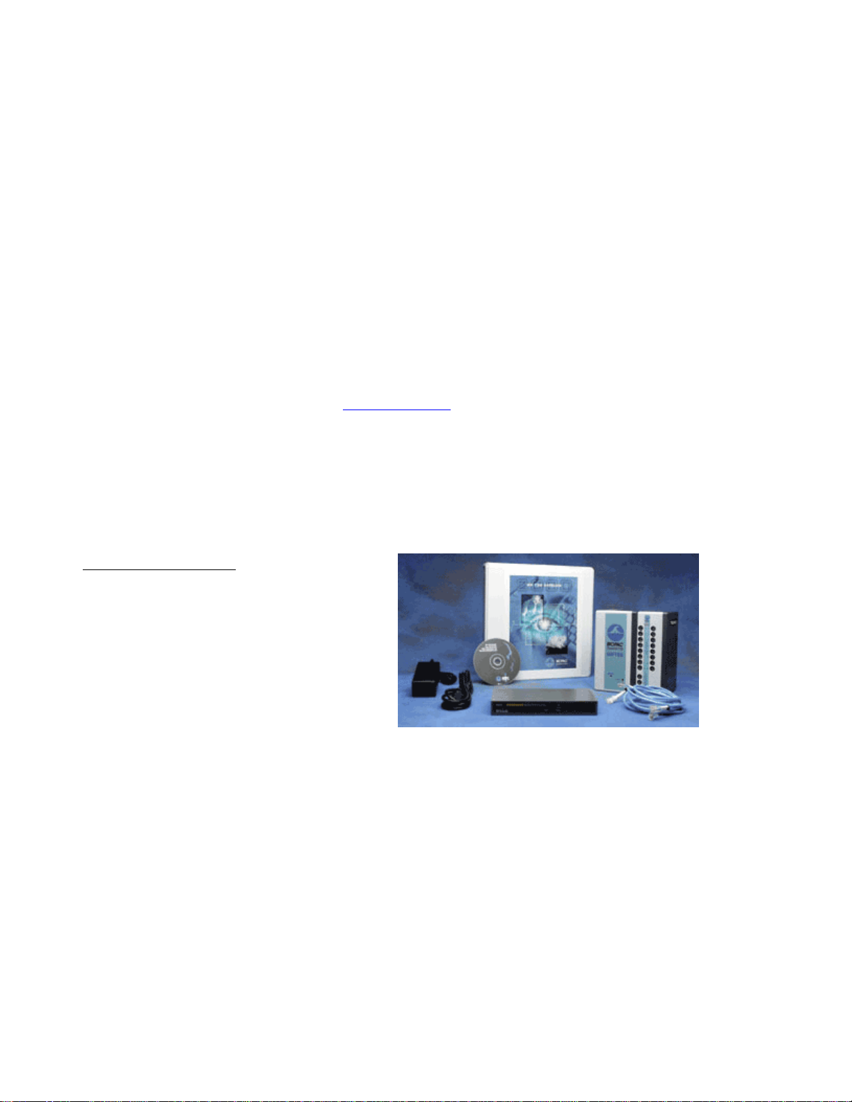
MP150 STARTER SYSTEM
MP150 System includes:
Data acquisition unit: MP150A-CE
Universal interface module: UIM100C
Ethernet Switch (for user-supplied Ethernet
card or adapter): ETHSW1
Transformer: AC150A
Cables: CBLETH1 (2)
AcqKnowledge
The MP150 high-speed data acquisition system utilizes the very latest in Ethernet technology. The MP150 is
compliant with any Ethernet (DLC) ready PC or Macintosh. This next generation product takes full advantage of
cutting edge technology. Access multiple MP150 devices located on a local area network and record data to any
computer connected to the same LAN. Record multiple channels with variable sample rates to maximize storage
efficiency. Record at speeds up to 400 kHz (aggregate).
Recommended MP150 configuration:
For the best possible performance, connect the MP System solely to the computer’s Ethernet port. For simultaneous
connection of the network and the MP System, the ETHSW1 is required. If a computer has no Ethernet port, users
need to install an industry standard PCI Ethernet card (Intel, 3COM, etc.). If a computer does not require
simultaneous connection to the network, it’s acceptable to use a standard crossover Ethernet cable to connect the
MP System to a computer.
®
software CD
*MP150 Specifications are on page
9.
2 MP System Hardware Guide
Page 3
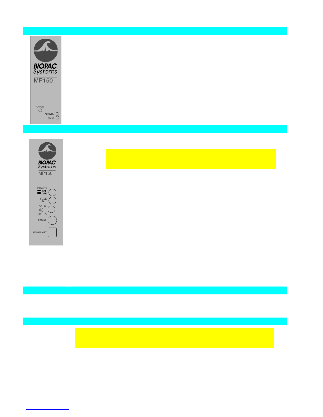
MP150 Symbology
Front panel
See “Light Status” section for functionality details.
POWER Green light Indicates MP150 Power status.
ACTIVITY Amber light Indicates data traffic to or from MP150— similar to
BUSY Green light Indicates MP150 data acquisition.
Back panel
Power ON Push in to power up the MP150
OFF Pop out to cut the flow of power to the MP150
IMPORTANT! The MP150 does not have a “Hardware Reset”
switch like your personal computer does. To reset the MP150 for any
reason, just click the power switch twice.
Fuse 2A 2 Amp fast-blow fuse holder; the maximum capacity of the fuse is 2 Amps.
To remove the fuse, use a screwdriver to remove the fuse cover,
which is located below the word Fuse.
DC Input Use the DC Input to connect a battery, AC/DC converter or other power
supply to the MP150.
The MP150 requires 12 VDC @ 2 Amps
The receptacle can accept a “+” (positive) input in the center of the
connector and a “−” (negative) input on the connector housing.
Serial port The MP150 can connect to the computer via a serial port, located just below
the word Serial (this connection is not normally used).
Uses a standard MINI DIN 8 connector.
Should only be used to connect the MP150 to a PC (via USB1W) or
Mac (via USB1M).
Ethernet The MP150 connects to the computer via a serial port, located just below
the word Ethernet.
Uses a standard RJ-Ethernet connector (10 base T).
Side panel
Module connections
The two connector inputs are designed to connect directly to the UIM100C.
Analog signals are transmitted through the 37-pin connector (upper right side)
Digital signals are transmitted through the 25-pin connector (lower-right side)
Bottom
Firmware Rollback Switch
IMPORTANT! This is NOT A RESET SWITCH
The Firmware Rollback Switch is located on the bottom of the MP150 unit and is
recessed to prevent accidental activation—it is NOT A RESET for the MP150 unit.
Warning! Activation of the Firmware Rollback Switch will cause the MP150 unit to
operate under the previous version of firmware loaded into the unit. Refer to Appendix F
of the AcqKnowledge Software Guide for procedural details.
Hard Disk activity light on any personal computer.
www.biopac.com 3
Page 4

ACTIVITY
BUSY
MODE DESCRIPTION
A Bright
B Bright
A Bright
B Blink
A Blink
B Bright
A Blink
B off
Self-Test
ACTIVITY and BUSY be bright for the duration of the self-test and setup process.
This may take 3 – 10 seconds, depending on MP150 internal memory.
During data acquisition, ACTIVITY reflects command/data traffic (for acquisition
Work
speeds of 1000 Hz or more, ACTIVITY will be permanently bright or blink at a high
frequency) and BUSY will be bright. It is normal for both lights to be on—this does
not indicate a problem unless you receive an Error Message on the computer screen.
ERROR: In rare cases, a serious problem may prevent a self-test and the lights may be
erratic: both on, both off, or any other static combination.
Error
Error The MP150 enters the Error Mode if a fatal error occurs during the Self-test Mode. In
the Error Mode, ACTIVITY is bright and BUSY is blinking at a frequency of 5 Hz.
Error If the self-test fails or setup fails, the Error mode is initiated and ACTIVITY will blink
at about 5 Hz rate and BUSY will remain bright.
Idle-1
Idle-2
ACTIVITY blinks twice
Double blink means:
- MP150 may be disconnected from LAN or,
- MP150 is connected to LAN but did not receive IP address from network’s
DHCP server and default 169.254.xxx.xxx address is self-assigned to MP150.
This is the standard state for MP150 connected to NIC through cross-over
network cable.
It means the MP150 is in working condition and ready for acquisition. AcqKnowledge
may communicate with the MP150 through a serial cable or through a network by
using 169.254.xxx.xxx address and/or cross-over cable.
ACTIVITY blinks once
with approximately 1.5-2 second interval and BUSY is OFF.
with approximately 1.5-2 second interval and BUSY is OFF.
Single blink means:
- MP150 is connected to LAN and received IP address from network’s DHCP
server.
It means the MP150 is in working condition and ready for acquisition.
A off
B off
Self-Test
Wait
Error
ACTIVITY and BUSY will go dark for less than 1 second at the end of the self-test
before proceeding to the Idle mode.
Under some conditions, such as when you have a dialog box open, AcqKnowledge
cannot send commands to the MP150. When command flow from the workstation
stops, the MP150 acts as if you have an open dialog and enters the Wait Mode to wait
for a command from the workstation it is “locked” to—commands from any other
work station will be ignored. When it receives a command, the MP150 return to the
Work mode. After five minutes with no command communication, the MP150 will
revert to the Idle mode.
ERROR: In rare cases, a serious problem may prevent a self-test and the lights may be
erratic: both on, both off, or a static combination.
4 MP System Hardware Guide
Page 5
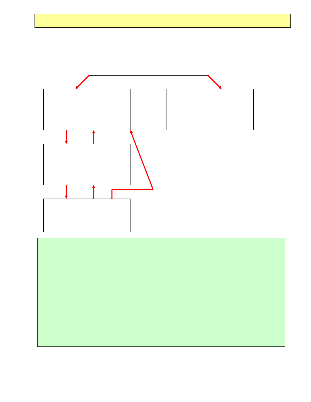
MP150 STATUS LIGHT PATHS
Startup (Power ON) > Self-test
When the MP150 is turned ON, ACTIVITY and
BUSY will shine for the duration of the self-test
and setup process. This may take 3 – 10 seconds,
depending on MP150 internal memory.
MP150 is waiting for any
command/request from
AcqKnoweldge or any workstation
or any interface.
Idle
[See Note 1]
The MP150 enters the Error Mode
if a fatal error occurs during the
Self-test Mode.
Error
MP150 receives/sends
MP150 receives/sends
commands/data to/from
commands/data to/from
AcqKnowledge.
AcqKnowledge.
Work
Work
[See Note 2]
[See Note 2]
MP150 cannot receive command
due to software condition (i.e.,
dialog box open).
Wait
[See Note 3]
NOTES
1. IDLE—Both light patterns are normal and indicate that the MP150 is waiting for a command—neither
indicates a problem with the MP150. The MP150 can switch between Idle-1 and Idle-2. Idle-1 or Idle-2
pattern indicates which IP address the MP150 is using:
• Idle-1: self-assigned address in 169.254.xxx.xxx network
• Idle-2: address from DHCP server).
2. WORK — When the MP150 receives any command from any workstation, it locks on to that workstation
and communicates with it exclusively. The MP150 “remembers” the active workstation and will ignore
commands from any other workstation. The MP150 usually remains in the Working Mode until you quit the
AcqKnowledge software.
3. WAIT — Under some conditions, such as when you have a dialog box open, AcqKnowledge cannot send
commands to the MP150. When command flow from the workstation stops, the MP150 acts as if you have
an open dialog and enters the Wait Mode to wait for a command from the workstation it is “locked” to—
commands from any other work station will be ignored. When it receives a command, the MP150 enters the
Work mode; if the MP150 does not receive a command within five minutes, it reverts to Idle.
www.biopac.com 5
Page 6
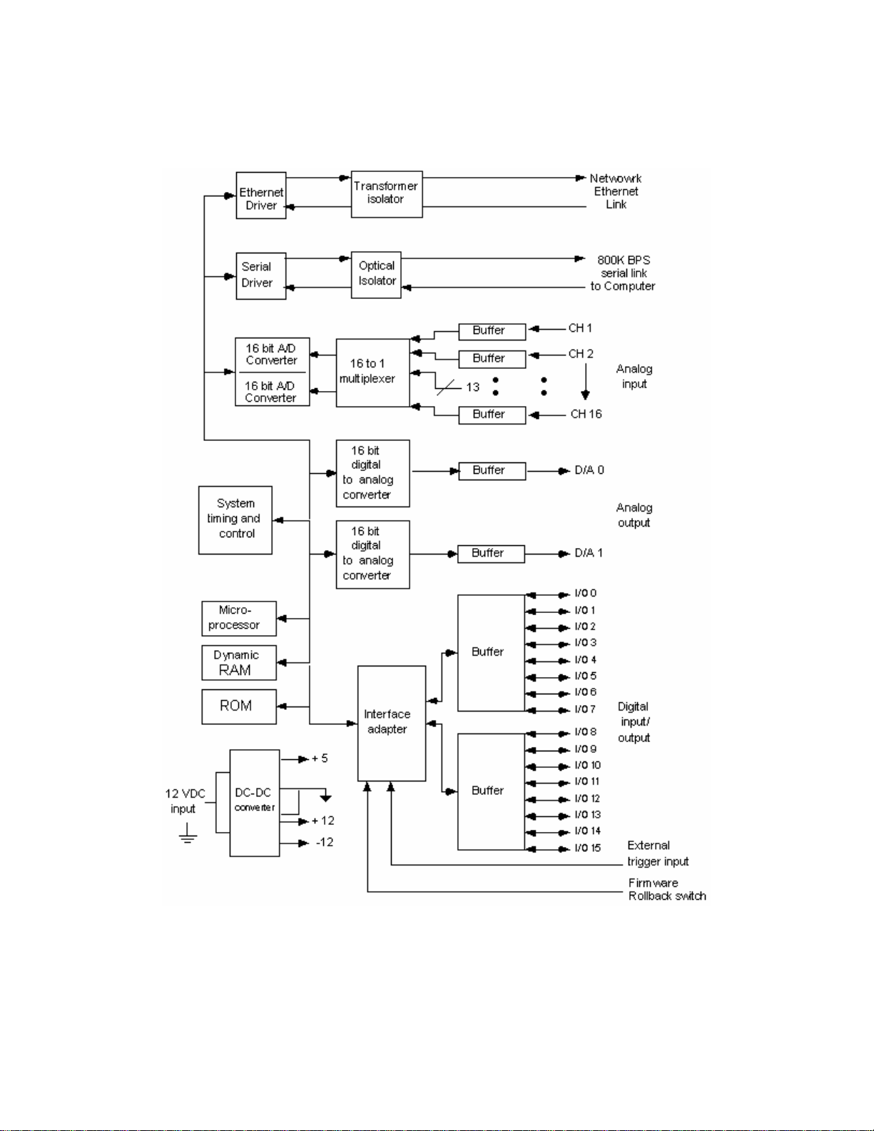
MP150A-CE Data Acquisition Unit Block Diagram
The MP150 has an internal microprocessor to control the data acquisition and communication with the computer.
There are 16 analog input channels, two analog output channels, 16 digital channels that can be used for either input
or output, and an external trigger input. The digital lines can be programmed as either inputs or outputs and function
in 8 channel blocks. Block 1 (I/O lines 0 through 7) can be programmed as either all inputs or all outputs,
independently of block 2 (I/O lines 8 through 15).
MP150A-CE block diagram
*MP150 Specifications are on page
6 MP System Hardware Guide
9.
Page 7

MP100 STARTER SYSTEM
*MP100 Specifications are on page
The MP100 system offers USB-ready data acquisition and analysis. Record multiple channels with differing sample
rates. Record at speeds up to 70 kHz or 16 kHz (aggregate to disk)
MP100 System includes
:
Data acquisition unit: MP100A-CE Transformer: AC100A
Universal interface module: UIM100C Cables: CBLSERA cable, CBLS100 cable set
USB adapter: USB1W (PC) or USB1M (Macintosh) AcqKnowledge
Recommended MP100 configuration:
For the best possible performance, connect the MP System to the computer’s USB port, with no other USB traffic
intensive devices (e.g. scanners, hard drives, cameras) running simultaneously. If a computer has no USB port, users
need to install an industry standard PCI USB card.
9.
®
software CD
MP100 Symbology
Front panel
POWER
BUSY
CABLE
Power status
MP100 acquisition status
On if MP100 is turned ON.
Off if MP10 is turned OFF.
On during acquisition or during the first 1-5
seconds after the MP100 is powered ON.
25-pin cable connection Digital signals
INPUTS
37-pin cable connection Analog signals
Back panel
Power switch
On powers up the MP100
Off cuts the flow of power to the MP100
Fuse holder
Next to the power switch is a 2 Amp fast-blow fuse holder.
To remove the fuse, use a screwdriver to remove the fuse cover,
which is located below the word Fuse.
The maximum capacity of the fuse is 2 Amps.
Back panel
DC Input
cont’d
The DC Input, located between the fuse holder and the serial cable, is where a
battery, AC/DC converter or other power supply connects to the MP100.
The power supply requirements for the MP100 are 12 VDC @ 1 Amp,
The receptacle is configured to accept a “+” (positive) input in the center of the
connector and a “−” (negative) input on the connector housing.
Serial port
The MP100 connects to the computer via a serial port, located just
below the word Serial.
Uses a standard MINI DIN 8 connector.
Should only be used to connect the MP100 to a PC or Macintosh.
www.biopac.com 7
Page 8
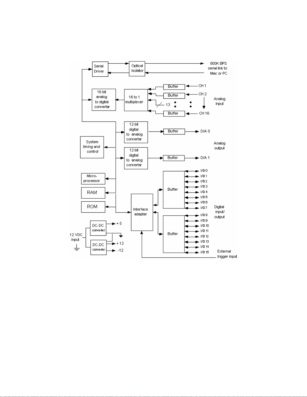
MP100A-CE Data Acquisition Uni Block Diagram
The MP100 has an internal microprocessor to control the data acquisition and communication with the computer.
There are 16 analog input channels, two analog output channels, 16 digital channels that can be used for either input
or output, and an external trigger input. The digital lines can be programmed as either inputs or outputs and function
in 8 channel blocks. Block 1 (I/O lines 0 through 7) can be programmed as either all inputs or all outputs,
independently of block 2 (I/O lines 8 through 15).
MP100 block diagram
*MP100 Specifications follow.
8 MP System Hardware Guide
Page 9

MP System Specifications — for MP150 and MP100
MP150 and MP100 Data Acquisition Unit Specifications:
Analog Inputs
Number of Channels: 16
Input Voltage Range: ±10V
A/D Resolution: 16 Bits
Accuracy (% of FSR): ±0.003
Application Programming Interfaces options:
• Hardware Interface BHAPI
• Software Interface ACKAPI
Input impedance: 1.0 MΩ
Analog Outputs
Number of Channels: 2
Output Voltage Range: ±10V
D/A Resolution: MP150: 16 bits, MP100: 12 Bits
Accuracy (% of FSR): MP150: ±0.003, MP100: ±0.02
Output Drive Current: ±5mA (max)
Output Impedance: 100Ω
Digital I/O
Number of Channels: 16
Voltage Levels: TTL, CMOS
Output Drive Current: ±20mA (max)
External Trigger Input: TTL, CMOS compatible
Time Base
Min Sample Rate: 2 samples/hour
Trigger Options: Internal, External or Signal Level
Power
Amplifier Module Isolation: Provided by the MP unit
CE Marking: EC Low Voltage and EMC Directives
Leakage current: <8µA (Normal), <400µA (Single Fault)
Fuse: 2A (fast blow)
Device specific specs MP150A MP100A
Max Sample Rate
MP Internal Memory:
200K samples/sec (400K aggregate) 70K samples/sec (70 K aggregate)
PC Memory/Disk: 200K samples/sec (400K aggregate) 11K samples/sec (16K aggregate)
Internal Buffer Size: 6M samples 16K samples
Serial Interface Type/Rate: Ethernet: DLC type I (10M bits/sec)
Serial: RS422 (800 Kbits/sec)
Serial: RS422 (800K bits/sec)
Transmission Type: Ethernet USB only (PC via USB1W or
Macintosh via USB1M)
Maximum cable length: 100 meters (Ethernet cable) 7 meters (USB + SERIAL cable)
Power Requirements: 12VDC @ 2 amp (uses AC150A) 12 VDC @ 1amp (uses AC100A)
Dimensions: 10cm x 11cm x 19cm 7cm x 29cm x 25cm
Weight: 1.0 kg 1.8 kg
OS Compatibility
Ethernet Interface
PC
Macintosh
USB Interface
PC
Macintosh
Windows 98, 98SE, 2000, NT 4.0
System 8.6 or better
Not supported
Not supported
Not supported
Not supported
Windows 98, 98SE, 2000
System 8.6 or better
www.biopac.com 9
Page 10

Isolation
Designed to satisfy the following Medical Safety Test Standards affiliated with IEC601-1:
Creepage and Air Clearance
Dielectric Strength
Patient Leakage Current
Contact BIOPAC for additional details.
Signal conditioning module compatibility
CO
100C EGG100C HLT100C PPG100C
2
DA100C EMG100C LDF100C RSP100C
EBI100C EOG100C MCE100C SKT100C
ECG100C ERS100C O
100C STM100C
2
EEG100C GSR100C OXY100C TEL100C
Cleaning procedures
Be sure to unplug the power supply from the MP150/100 before cleaning. To clean the MP150/100, use a
damp, soft cloth. Abrasive cleaners are not recommended as they might damage the housing. Do not
immerse the MP150/100 or any of its components, as this can damage the system. Let the unit air-dry until
it is safe to reconnect the power supply.
AC150/100A Power Supplies
The 12-volt in-line switching transformer connects the MP unit to the AC mains wall outlet. One
transformer is included with each MP System; replacements can be ordered separately.
10 MP System Hardware Guide
Page 11
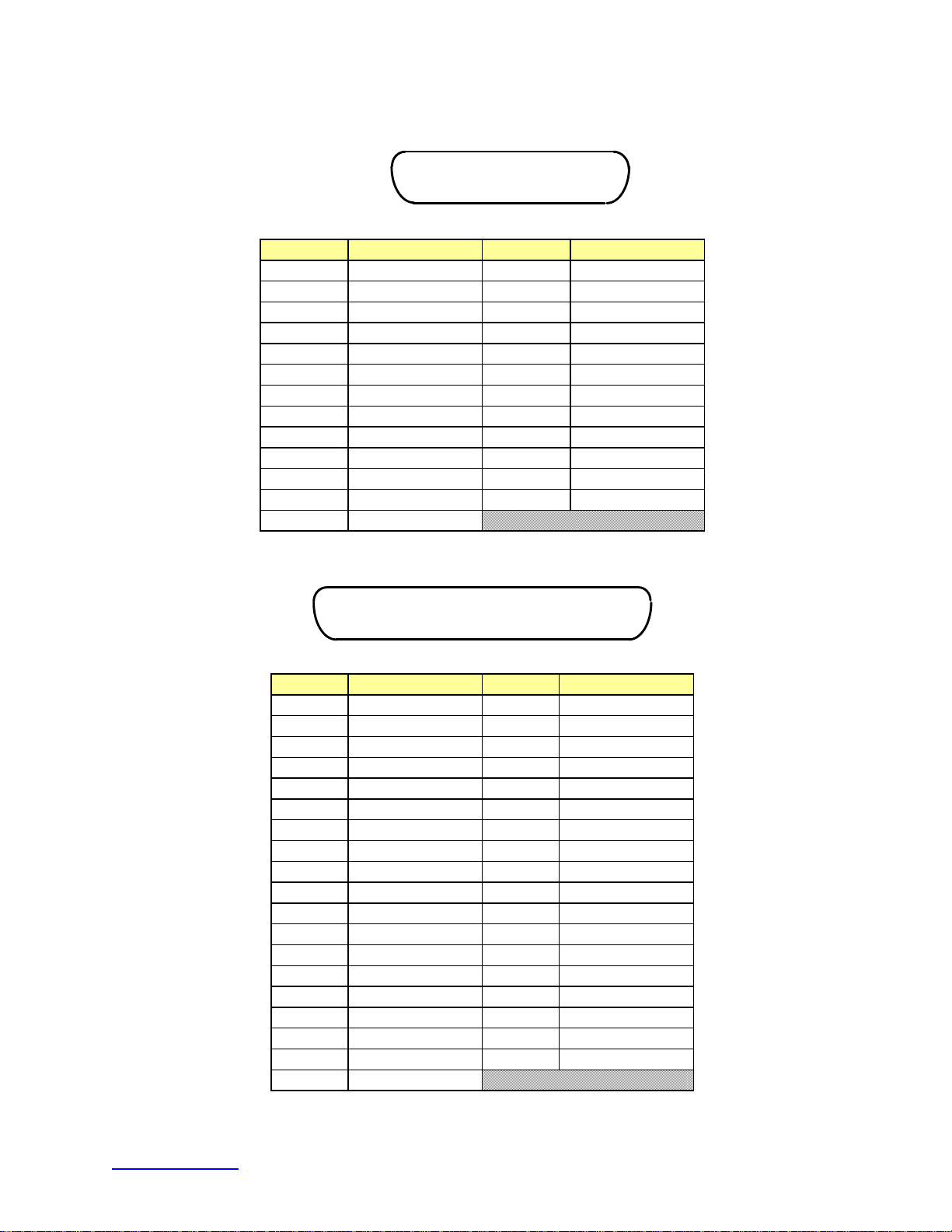
MP SYSTEM PIN-OUTS — FOR MP150 AND MP100
Digital DSUB 25 (male) Pin-outs
1 2 3 4 5
6 7 8 9
10 11 12 13
14 15 16 20 21 22
17 18 19
DIGITAL
23 24 25
Pin Description Pin Description
5
6
7
8
9
10
11
12
13
1
2
3
4
I/O 0
I/O 1
I/O 2
I/O 3
GND D
GND D
EXT T
+5 VD
+5 VD
I/O 8
I/O 9
I/O 10
I/O 11
14
15
16
17
18
19
20
21
22
23
24
25
I/O 4
I/O 5
I/O 6
I/O 7
GND A
Out 1
Out 0
GND A
I/O 12
I/O 13
I/O 14
I/O 15
Analog DSUB 37 (male) Pin-outs
1 2 3 4 5
6 7 8 9 10 11 12 13 14 15 16 17 18 19
26 27 28 20 21 22 23 24 25 32 33 34 35 36 37
29 30 31
ANALOG
Pin Description Pin Description
1
2
3
4
5
6
7
8
9
10
11
12
13
14
15
16
17
18
19
GND A
GND A
GND A
GND A
GND A
GND A
GND A
GND A
+12 V
GND A
-12 V
GND A
GND A
GND A
GND A
GND A
GND A
GND A
GND A
20
21
22
23
24
25
26
27
28
29
30
31
32
33
34
35
36
37
CH 1
CH 2
CH 3
CH 4
CH 5
CH 6
CH 7
CH 8
+12 V
- 12 V
CH 9
CH 10
CH 11
CH 12
CH 13
CH 14
CH 15
CH 16
www.biopac.com 11
Page 12
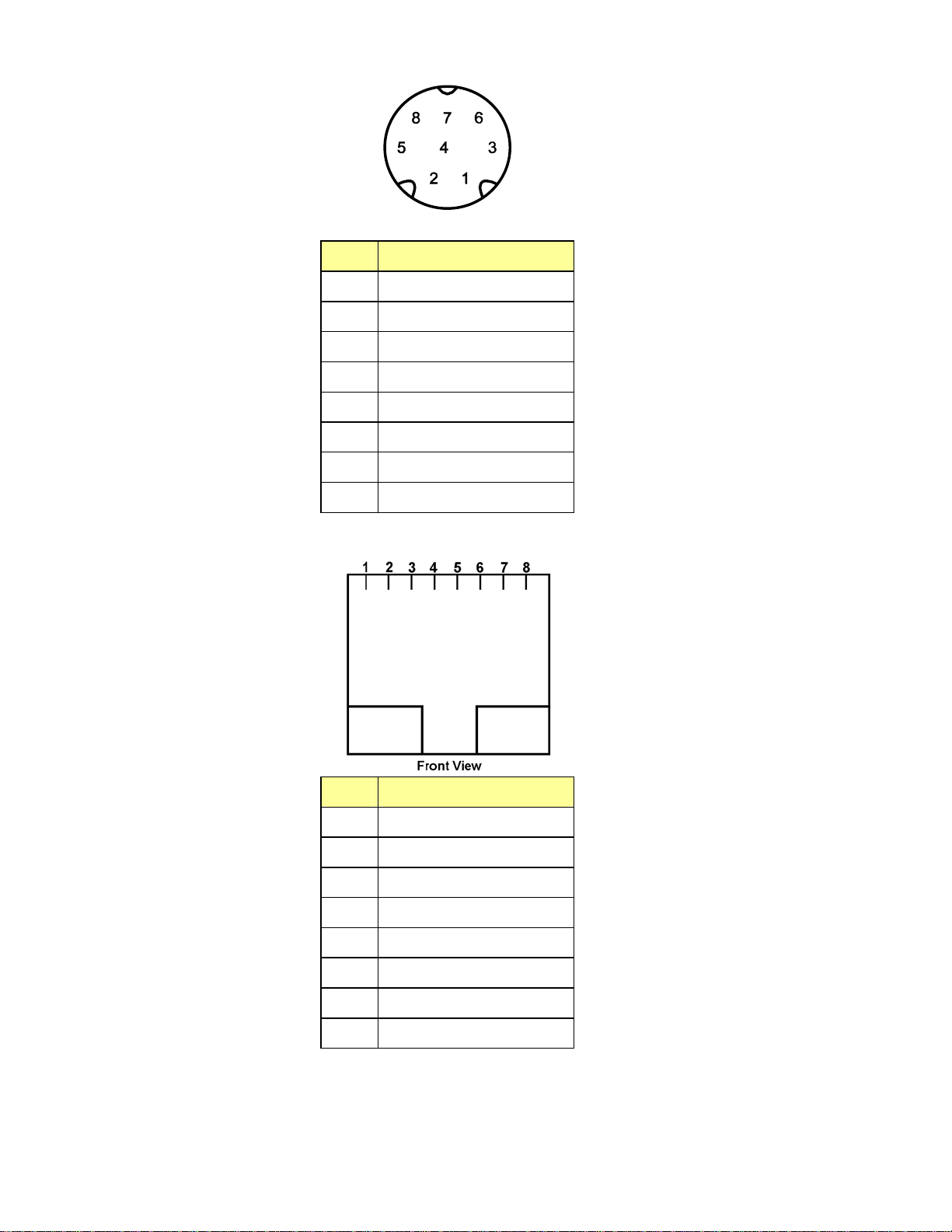
Serial MINI DIN 8 (female) Pin-outs
SERIAL
Pin Description
No Connection
1
Clock (MP Output)
2
Rx+ (MP Input)
3
GND computer
4
Tx+ (MP Output)
5
Rx- (MP Input)
6
No Connection
7
Tx- (MP Output)
8
Ethernet connector Pin-outs (for model MP150 only)
Pin Description
TXD+
1
TXD-
2
RXD+
3
No Connection
4
No Connection
5
RXD-
6
No Connection
7
No Connection
8
12 MP System Hardware Guide
Page 13

Cleaning & Disinfecting BIOPAC Components
The following disinfectants are recommended for LIQUID “COLD” sterilization of BIOPAC transducers:
• Cidex
• Perform
• Terralin
®
OPA Disinfectant Solution, Johnson & Johnson
®
Powder Disinfectant Concentrate, Schülke & Mayr
®
, Liquid Disinfectant Concentrate, Schülke & Mayr
Always follow the
manufacturer’s directions.
AFT25 Facemask
• See detailed guide shipped with the product; also available at www.biopac.com.
EL250 Series Electrodes
• Store electrodes in clean, dry area.
• After use, clean electrode with cold to tepid water
• DO NOT use hot water.
• Cotton swabs are suggested.
• Let the electrode dry completely before storing it.
• DO NOT allow the electrodes to come in contact with each other during storage.
• Electrodes may form a brown coating if they have not been used regularly. To remove the coating,
gently polish the surface of the electrode element with non-metallic material or wipe it with mild
ammonium hydroxide. Rinse with water and store the electrode in a clean, dry container.
GASSYS2
• See page 246 or detailed guide shipped with the product; also available at www.biopac.com.
LDF100C
• See page 175.
Probes
• Immersion temperature probes can be cleaned using standard liquid disinfectant methods, with
direct immersion for the recommended period.
• Non-immersion probes can be wiped down with liquid disinfectant or alcohol.
RX137 Series Airflow Heads
• Thorough cleaning retains precise measurements. Disinfecting is only useful on a previously
cleaned apparatus. Using a gas for disinfecting does not provide cleaning. An appropriate
disinfectant solution can clean and disinfect simultaneously.
1. Immerse the apparatus in the liquid. It can be completely immersed since the electrical part
is waterproof; a 30- to 60-minute bath is usually sufficient to detach or dissolve the dirt.
2. Rinse under a strong tap.
3. Rinse with distilled or demineralized water.
4. Use air or another compressed gas to dry the apparatus. Blow through the screen and in
each pressure tube; a pressure of 5 to 6 bars is acceptable.
5. Finish drying with atmospheric air or with a warm blow dryer (hair dryer).
• WARNING!
Do not use organic solvents Dilute the disinfectant (as for hand washing)
Do not heat the apparatus above 50ºC Never touch the screen with a tool
• Examples of liquids that may be used: Cidex, Glutaral, Glutaraldéhyde
• Example of gas that may be used: Ethylene oxide
TSD130 Series Goniomoters & Torsiometers
• Important: Disconnect sensors from instrumentation before cleaning or disinfecting.
• Cleaning: Wipe the sensors with a damp cloth, or a cloth moistened with soapy water. Do not use
solvents, strong alkaline or acidic materials to clean the sensors.
• Disinfection: Wipe the sensors with a cloth moistened with disinfectant.
TSD140 Probes
• See page 175.
www.biopac.com 13
Page 14

Magnetic Resonance Imaging and MP System Components
MRI-compatibility Statement
“Radiotranslucent” and “MRI-compatible” products are ones which are brought into the MRI Chamber
room. All other BIOPAC products can be brought into the MRI control room, as this room is not subject to
the high field gradients in the MRI.
BIOPAC defines “Radiotranslucent” products as products that have no thermally or electrically conductive
metal and no robustly magnetically susceptable materials (ie. Ferromagnetic, Ferrimagnetic) in the applied
part. These products may include electrically conductive materials (i.e. carbon fiber, electrode gel), but due
to relatively low instrinic electrical conductance, self-heating effects due to eddy currents are typically
minimal. These products are best suited for MRI and fMRI applications.
BIOPAC defines “MRI-compatible” products as products that have some thermally and electrically
conductive metals, but no robustly magnetically susceptable materials (i.e. Ferromagnetic, Ferrimagnetic)
in the applied part. These may be suitable for some MRI and fMRI applications. Because these products
include some relatively high thermal and electrically conductive components, self-heating effects due to
eddy currents can become problematic. In cases where this problem manifests, some consideration to
thermal insulation from the thermally and electrically conductive applied part to the subject is relevant.
BIOPAC defines “Radio-opaque” products as products whose applied part is easily visible in an x-ray
machine viewer so it can be better manipulated. Radiotranslucent in this context implies that the applied
part is only partially or not visible in the x-ray viewer. Radio-opaque products are not necessarily suitable
for use in MRI or fMRI applications.
MRI Components
MRI Cable/Filter Sets The table below illustrates the components of each cable/filter set. See below
for full descriptions of each included cable and filter.
Cable/Filter Sets
MECMRI-DA — For recordings
MRIRFIF
MRIRFIF-2
MECMRI-1
MECMRI-2
MECMRI-3
MECMRI-4
MECMRI-5
MECMRI-6
with a transducer in the MRI
chamber room and the DA100C
in the MRI control room. Use to
connect directly to the following
X
X
transducers: Medium Flow
Pneumotach (TSD117-MRI) or
Hand clench dynamometer
(TSD121B-MRI).
MECMRI-HLT — For
recordings in the MRI with the
HLT100C. Use to connect
directly to the following
X
X
transducers: TSD115-MRI or
TSD131-MRI.
MECMRI-OXY — Use to
connect to the OXY100C Pulse
Oximeter and TSD123A/B
X
Oximetry transducers for MRI
applications.
14 MP System Hardware Guide
Page 15

Cable/Filter Sets
MECMRI-STMISO — Use to
connect directly to the
following stim isolation
adapters: STMISOC,
STMISOD, or STMISOE.
MECMRI-TRANS —For
Transducer recordings in the
MRI. Use to connect directly to
the following transducer
amplifiers: GSR100C,
PPG100C, RSP100C, or
SKT100C.
Connection Sequence: Subject
to transducer to MECMRI-1 to
MRIRFIF to MECMRI-3 to
transducer module.
MECMRI-BIOP —
Component set for Biopotential
recordings in the MRI. Use to
connect directly to any of the
following biopotential
amplifiers: ECG100C,
EEG100C, EGG100C,
EMG100C, EOG100C,
ERS100C.
MRIRFIF
X
X
X
MRIRFIF-2
MECMRI-1
MECMRI-2
MECMRI-3
MECMRI-4
X
X
X X
X X
MECMRI-5
MECMRI-6
Connection Sequence: Subject
to electrodes to leads to
MECMRI-1 to MRIRFIF to
MECMRI-2 to Biopotential
Module
www.biopac.com 15
Page 16
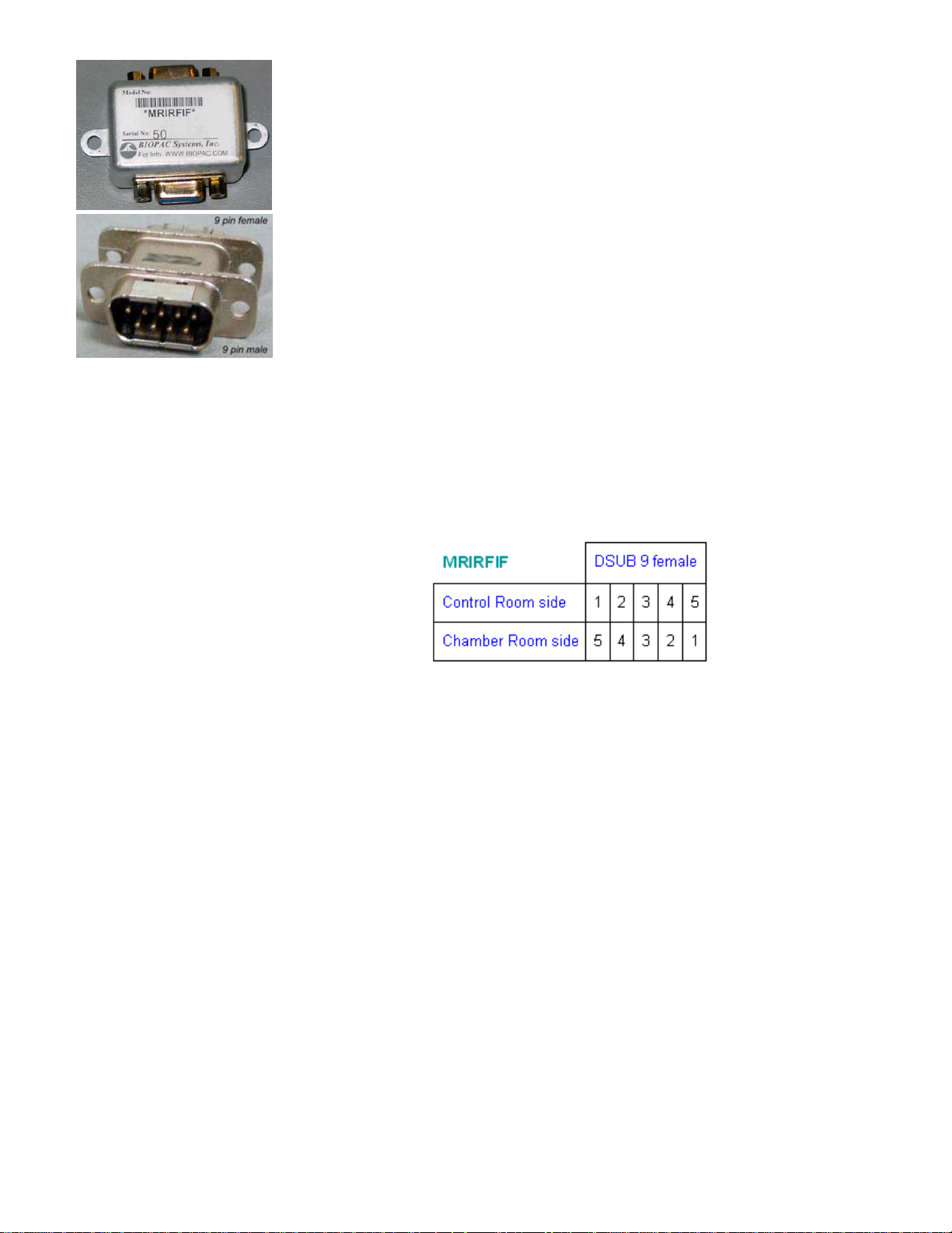
MRIRFIF
MRIRFIF is a five-line Pi filter set, designed for interfacing between the
MECMRI-1 chamber room cable and any of the MRI control room cables
(MECMRI2-MECMRI6).
See also: App Note 223 Physiological Measurements in Magnetic Resonance
Imaging Systems Using BIOPAC Equipment.
• MRIRFIF: -3 dB point = 100 kHz
• MRIRFIF-2: -3 dB point = 1 MHz
• MRIRFIF + MRIRFIF -2 = 3 dB point = 70 kHz
o attenuation is -60 db from 7 MHz to 1,000 MHz
o attenuation slope from 70 kHz to 7 Mhz is 30 dB per decade
This Pi filter set has a dielectric withstand voltage of 1,500 VDC and is thus
compatible with IEC 60601-1 requirements. The Pi filter set is designed to
shunt RF energy from the MRI or control room chambers to EARTH
GROUND without sacrificing CMRR performance for the recording of small
valued biopotential or transducer signals.
The MRIRFIF’s symmetrical construction, with dual 9-pin female
connectors, results in a pin swap for pins 1, 2, 3, 4, 5, regarding signal flow
as illustrated here:
Accordingly, if the MRIRFIF and associated cable assemblies (such as
MECMRI-#) are used with any existing patch panel connectors, the existing
connector must be a male/female 9-pin straight-through DSUB patch or filter
connector. The male side of the existing connector must be on the Control
room side to successfully connect the MRIRFIF to this connector.
Best performance is obtained by robustly attaching the GROUND of the
MRIRFIF (metal enclosure) to EARTH GROUND at the junction panel.
Mounting the MRIRFIF to the junction panel via the included L-bracket
establishes an excellent ground to the panel. EARTH GROUND must be
robust and held to the same potential as MAINS GROUND.
Leakage Currents
The IEC 60601-1 standard specifies a leakage current of 5 ma assuming
double fault conditions. 265 VAC at 60 Hz will source 5 ma into a reactance
of 53 K. This reactance is equivalent to an effective subject capacitance to
equipment ground of 0.05 uF. The BIOPAC MP unit establishes a subject to
ground capacitance of 0.005 uF. The Pi filter set (MRIRFIF + MRIRFIF-2)
incorporates a 0.003 uF subject capacitance to ground. Accordingly, even
with 15 MECMRI cables—with 15 MRIRFIFs—this results in a capacitance
of .05 uF, which is 100% of the IEC 60601-1 limit, assuming mains is 265
VAC at 60 Hz.
16 MP System Hardware Guide
Page 17
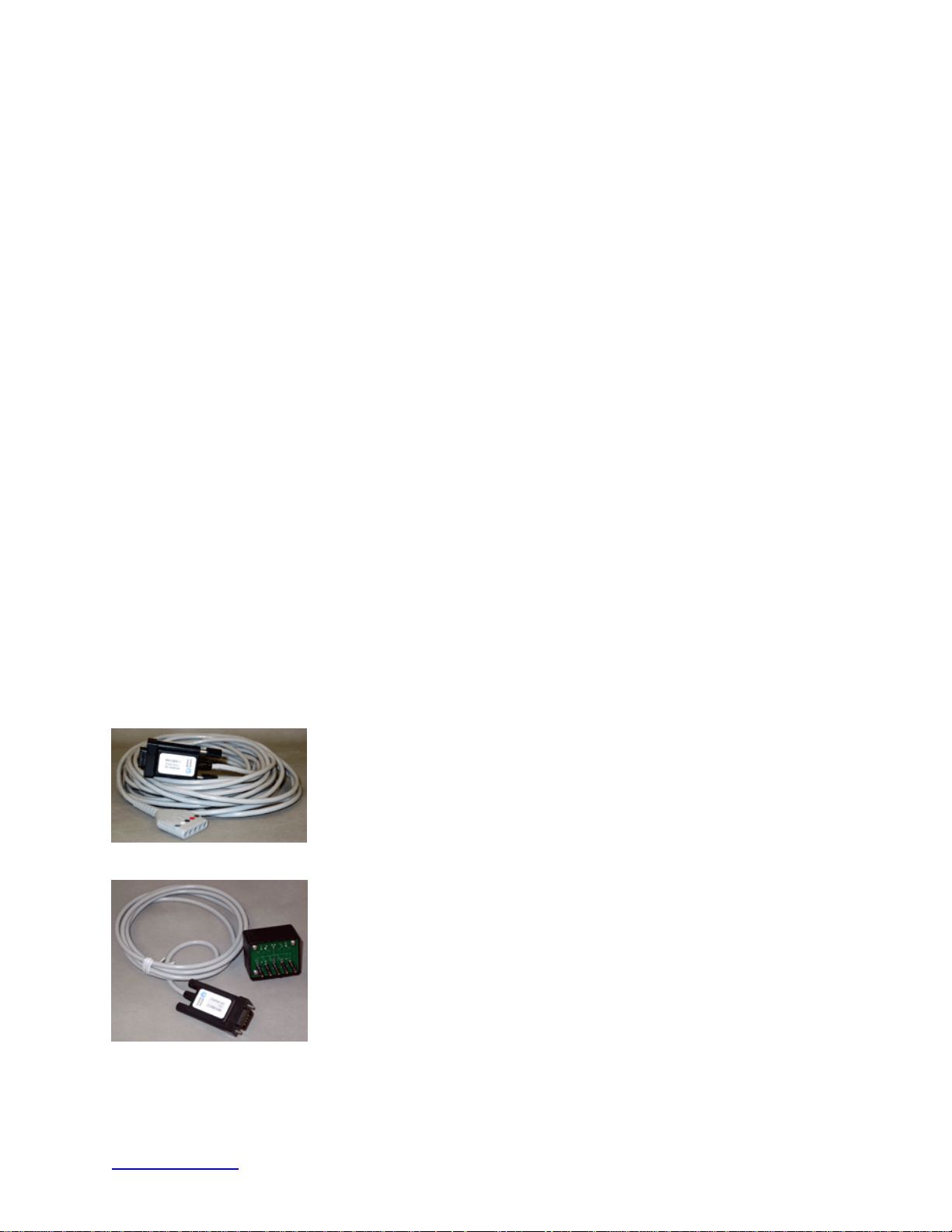
MRIRFIF-2
This filter has a dielectric withstand voltage of 1,500 VDC and is compatible
with IEC60601-1 requirements. The filter is designed to shunt RF energy
from the MRI or control room chambers to EARTH GROUND without
sacrificing CMRR performance for the recording of small valued signals.
• MRIRFIF-2: -3 dB point = 1 MHz
This nine-line Pi filter is designed for interfacing between the MRI chamber
room cable (MECMRI-OXY) and the MRI control room cable (OXY-MRI).
If the MECMRI-OXY set is used with an existing patch panel connector, the
MRIRFIF-2 should be plugged into the Control Room side of the patch panel
connector, which must be a male/female 9-pin straight-through DSUB patch
or filter connector. The male side of the existing connector must be on the
Control room side to successfully connect to the MRIRFIF-2 and OXY
cables.
Best performance is obtained by robustly attaching the GROUND of the
MRIRFIF-2 (metal enclosure) to EARTH GROUND at the junction panel.
Mounting the MRIRFIF-2 to the junction panel establishes an excellent
ground to the panel. EARTH GROUND must be robust and held to the same
potential as MAINS GROUND.
Leakage Currents
The IEC 60601-1 standard specifies a leakage current of 5 ma assuming
double fault conditions. 265 VAC at 60 Hz will source 5 ma into a reactance
of 53 K. This reactance is equivalent to an effective subject capacitance to
equipment ground of 0.05 uF. The BIOPAC MP unit establishes a subject to
ground capacitance of 0.005 uF, and the Pi filter (MRIRFIF-2) incorporates a
0.0018 uF subject capacitance to ground. Accordingly, even with 16
MECMRI cables with 16 MRIRFIFs, this results in a capacitance of .0338
uF, which is 68% of the IEC 60601-1 limit, assuming mains is 265 VAC at
60 Hz.
MECMRI-1
This is a Biopotential or Transducer cable for use inside the MRI chamber
room. It supports one to five subject or transducer electrical connections and
is 8 meters long. The cable incorporates a plastic housed DSUB9 Male
connector to panel mount with the chamber room exposed DSUB9 female
connector of the MRIRFIF.
MECMRI-2
This is a Biopotential cable for use inside the MRI control room. It supports
one to five subject electrical connections and is 2 meters long. The cable
incorporates a plastic housed DSUB9 Male connector to panel mount with
the control room exposed DSUB9 female connector of the MRIRFIF. This
cable connects directly to any of the following
ECG100C, EEG100C, EGG100C, EMG100C, EOG100C, ERS100C.
biopotential amplifiers:
MECMRI-3
This is a Transducer cable for use inside the MRI control room. It supports
one- to three-subject transducer connections and is 2 meters long. The cable
incorporates a plastic housed DSUB9 Male connector to panel mount with
www.biopac.com 17
Page 18

the control room exposed DSUB9 female connector of the MRIRFIF.
• This cable connects directly to any of the following
transducer
amplifiers: GSR100C, PPG100C, RSP100C, SKT100C.
MECMRI-4
This cable is used inside the MRI control room. It supports one channel of
subject stimulator connection and is 2 meters long. The cable incorporates a
plastic housed DSUB9 Male connector to panel mount with the control room
exposed DSUB9 female connector of the MRIRFIF interference filter. This
cable connects directly to any of the following stim isolatation adapters:
STMISOC, STMISOD, or STMISOE.
Note One MECMRI-4 comes with the MECMRI-STIMISO setup kit.
MECMRI-5
This 2-meter cable is used inside the MRI control room. It supports one
channel of general-purpose transducer output and connects directly to the
DA100C high-level transducer module and the MRIRFIF interference filter.
Cable incorporates a plastic housed DSUB9 male connector to panel mount
with the control room exposed DSUB9 female connector of the MRIRFIF
interference filter.
Note One MECMRI-5 is included with the MECMRI-DA setup kit.
MECMRI-6
Setup Guidelines
This cable is used inside the MRI control room. It supports one channel of
high-level transducer output and is 2 meters long. The cable incorporates a
plastic housed DSUB9 Male connector to panel mount with the control room
exposed DSUB9 female connector of the MRIRFIF interference filter. This
cable connects directly to the HLT100C high level transducer module.
Note One MECMRI-6 is included with the MECMRI-HLT setup kit.
OXYMRI
Use this 8-meter MRI chamber room cable for one channel of pulse oximeter
connection via TSD123A or TSD123B. One end terminates in a connector
that accepts the TSD123A or the TSD123B; the other end terminates in a
plastic-housed DSUB9 male connector to panel mount with the chamber
room exposed DSUB9 female connector of the MRIRFIF-2 interference
filter.
MECMRI-OXY
This 2-meter MRI control room cable provides one channel of connection to
the OXY100C. One end terminates for connection to the OXY100C; the other
end terminates in a plastic-housed DSUB9 male connector to panel mount
with the control room exposed DSUB9 female connector of the MRIRFIF-2
filter.
See
App Note AH-223 Physiological Measurements using BIOPAC in MRI Systems
App Note AH-230 Connections for Physiological Signals in an MRI
Contact BIOPAC if you have questions regarding set up and grounding to maintain subject
safety in accordance with IEC 60601-1.
18 MP System Hardware Guide
Page 19

Leakage Currents
The IEC 60601-1 standard specifies a leakage current of 5 ma assuming double fault conditions. 265
VAC at 60 Hz will source 5ma into a reactance of 53 K. This reactance is equivalent to an effective
subject capacitance to equipment ground of 0.05uF. The BIOPAC MP unit establishes a subject to
ground capacitance of 0.005 uF. The Pi filter (MRIRFIF) incorporates a 0.002uF subject capacitance to
ground (2 of 0.001 uF caps). Accordingly, even with 16 MECMRI cables—with 16 MRIRFIFs—this
results in a capacitance of .037 uF, which is 74% of the IEC 60601-1 limit, assuming mains is 265 VAC
at 60 Hz.
General recommendations for use:
Try to use pressure-based measurements in the MRI whenever possible, given the option. These
measurements are very safe and they are instrinsically radio translucent and they do not couple EMI...plus
they are always less expensive to implement. Pressure based measurements can record many physiological
variables (finger tapping pressure, blood pressure, pulse, hand grip strength, variable assessment,
heartsounds, body movements, smiling/frowning)
Where possible, couple all electrical signals via MECMRI cables.
Recommendations for specific applications:
• Airflow
o higher airflow: use AFT21 or AFT22 or AFT25 with lots of AFT7 or AFT12 tubing to
TSD117 (in Control room)
o low airflow use TSD127 with dual AFT30 tubing to TSD160A (in Control room)
• Biopotential recording: use LEAD108A and EL508.
• Blood pressure, use RX-120 series, with dual AFT30 Tubing and TSD104A (in Control Room)
• Blood Volume Pulse and O2SAT: use TSD123A or TSD123B, with special extension to 9 pin
patch D-filter and custom cable to OXY100C...no MECMRI specific cable needed (custom)
• Finger twitch, use SS61L (w/long cable) to MRIRFIF to custom cable to DA100C.
• For GSR measurements, use LEAD108A to record via:
o electrodes: EL507 or EL508 (hypersaturated-gel electrodes) or EL509 (dry electrode and
add gel).
o or transducer: TSD203 with GEL101
• Hand strength (dynamometry), use SS25LA (w/long cable) to MRIRFIF to custom cable to
DA100C
• Laser Doppler Flow measurements have the problem of proximity of LDF unit to magnet (only 2
meters), so these are best used when short distances can be tolerated from MRI to LDF unit. This
would be the case with smaller bore magnets, which are used for animal work. The best choices
here are the disposable probes because they will provide extra length, with disposable fiber +
driver. If the LDF100C is to be used with humans for MRI or fMRI, contact BIOPAC to discuss
custom LDF probe options for longer lengths.
• Pressure-based signals: route via waveguide using AFT30 series tubing
• Pulse measurements, use TSD110 with AFT30 tubing and TSD160A (secure with TAPE1)
• Respiration rate use TSD201or TSD202A (via thermistor over nose) with MECMRI-TRANS to
appropriate amp.
• Skin temperature, use TSD202A with TAPE1, with MECMRI-TRANS to SKT100C
• Stimulation, use LEAD108 (shorter carbon leads) and EL508 or EL509
• Trigger – see DTU100
Digital Trigger, page 91
• Variable assessment, use TSD115A to MRIRFIF to custom cable to DA100C
• Variable assessment/hand strength: use pump bulb and AFT30 tubing to TSD160 series or
TSD104A.
www.biopac.com 19
Page 20

Safety Issues
Caution is required when employing electrode leads and electrodes in an MRI environment. Under certain
conditions, single fault and otherwise, low impedance conduction through the subject represents a potential
hazard due to currents that may be induced in loops placed in the time-varying MRI field gradients and RF
fields, and due to body movement in the static MRI field. Low impedance conduction can result in
significant heating at the electrode/skin junction, because this point is often the part of the signal path with
the highest impedance. Sufficient heating at the electrode/skin juction could result in burns.
• For more information, read Methodological Issues in EEG-correlated Functional MRI Experiments
(Lemieux L, Allen PJ, Krakow K, Symms MR, Fish DR; International Journal of
Bioelectromagnetism 1999; 1: 87-95).
Important Note
BIOPAC Systems, Inc. products (including instruments, components, accessories, electrodes and
electrode leads) are designed for educational and research applications. BIOPAC does not condone
the use of its products for clinical medical applications. Products provided by BIOPAC are not
intended for the diagnosis, mitigation, treatment, cure or prevention of disease.
20 MP System Hardware Guide
Page 21

MP System Applications
Features
With proper hardware selection and setup, the MP System with AcqKnowledge software can be used for a
wide array of application features. See the MP System Guide for descriptions of the following features. For
additional support, or for help with an unlisted application, please contact the BIOPAC Technical Support
Division — an Applications Specialist will be glad to help you.
Active Electrodes
Allergies
Amplitude Histogram
Anaerobic Threshold
Animal studies
Auditory Evoked Response (AER)
Automate Acquisition Protocols
Automated Data Analysis
Automatic Data Reduction
Autonomic Nervous System Studies
Biomechanics Measurements
Blood Flow / Blood Pressure /Blood Volume
Body Composition Analysis
Breath-By-Breath Respiratory Gas Analysis
Cardiac Output
Cardiology Research
Cell Transport
Cerebral Blood Flow
Chaos Plots
Common Interface Connections
Connect to MP Systems
Control Pumps and Valves
Cross- and Auto-correlation
Current Clamping
Defibrillation & Electrocautery
Dividing EEG into Specific Epochs
ECG Analysis
ECG Recordings, 12-Lead
ECG Recordings, 6-Lead
EEG Spectral Analysis
Einthoven’s Triangle
EMG and Force
EMG Power Spectrum Analysis
End-tidal CO2
Episode Counting
Ergonomics Evaluation
Event-related Potentials
Evoked Response
Exercise Physiology
External equipment, controlling
Extra-cellular Spike Recording
Facial EMG
FFT & Histograms
FFT for Frequency Analysis
Field Potential Measurements
Fine Wire EMG
Forced Expiratory Flow & Volume
Gait Analysis
Gastric Myoelectric Activity
Gastric Slow Wave Propagation
Gastrointestinal Motility Analysis
Hardware Flexibility
Heart Rate Variability
Heart Sounds
Histogram Analysis
Imaging Equipment, Interfacing
Indirect Blood Pressure Recordings
Integrated (RMS) EMG
Interface with Existing Equipment
Interface with Third-party transducer
Invasive Electrode Measurements
Ion-selective Micro-electrode Interfacing
Iontophoresis
Irritants & Inflammation
Isolated Inputs & Outputs
Isolated Lung Studies
Isometric Contraction
Isotonic Contraction
Jewett Sequence
Langendorff Heart Preparations
Laser Doppler Flowmetry
Left Cardiac Work
Long-term Monitoring
Lung Volume Measurement
LVP
Median & Mean Frequency Analysis
Micro-electrode signal amplification
Migrating Myoelectric Complex
Motor Unit Action Potential
Movement Analysis
MRI Applications
Multi-Channel Sleep Recording
Nerve Conduction Studies
Neurology Research
Noninvasive Cardiac Output
Noninvasive Electrode Measurements
Nystagmus Investigation
Oculomotor Research
Off-line ECG Averaging
On-line Analysis
On-line ECG Analysis
Orthostatic Testing
Peripheral Blood Flow
Peristaltic (Slow Wave) Propagation
Planted Tissue
Pressure Volume Loops
Psychophysiology
Pulsatile Tissue Studies
Pulse Rate Measurement
Pulse Transit Time
Range of Motion
Real-time EEG Filtering
www.biopac.com 21
Page 22

Real-time EEG Filtering
Recurrent Patterns
Regional Blood Flow
Relative BP Measurement
Remote Monitoring
Respiration Monitoring
Respiratory Exchange Ratio
Rheumatology
Saccadic Eye Movements
Sexual Arousal Studies
Signal Averaging
Simultaneous Monitoring
Single Channel Analysis
Single-fiber EMG
Software-controlled Stimulator
Somatosensory Evoked Response
Spectral Analysis
Spike Counting
SpO2 Analysis
Stand Alone Amplifiers
Standard Operating Procedures
Startle Eye Blink Tests
Startle Response
Stimulator, software-controlled
Systemic Vascular Resistance
Template Analysis
Tissue Bath Monitoring
Tissue Conductance Measurement
Tissue Magnitude & Phase Modeling
Tissue Resistance & Reactance
Ussing Chamber Measurements
Ventricular Late Potentials
Vestibular Function
Video Capture, Synchronous
Visual Attention
Visual Evoked Response
VO2 Consumption
Volume/Flow Loop Relationships
Working Heart Preparations
22 MP System Hardware Guide
Page 23

Application Notes
BIOPAC has prepared a wide variety of application notes as a useful source of information concerning
certain operations and procedures. The notes are static pages that provide detailed technical information
about either a product or application. A partial list of Application Notes follows.
You can view or print application notes directly from the “Support” section of the BIOPAC web site
www.biopac.com.
APP NOTE Application
#AH101 Transducer Calibration and Signal Re-Scaling
#AH102 Biopotential Amplifier Testing using CBLCAL
#AH103 Remote Monitoring System (TEL100C)
#AS105 Auditory Brainstem Response (ABR) Testing
#AS105b ABR Testing for Jewett Sequence
#AS108 Data Reduction of Large Files
#AS109 3-, 6-, and 12-Lead ECG
#AH110 Amplifier Baseline (Offset) Adjustment
#AS111 Nerve Conduction Velocity
#AH114 TSD107A Pneumotach Transducer
#AH114b TSD107B Pneumotach Transducer
#AS115 Hemodynamic Measurements — Part I
#AS116 Hemodynamic Measurements — Part II
#AS117 Pulse Transit Time and Velocity Calculation
#AS118 EMG Signal Analysis
#AS119 EMG Power Spectrum Analysis
#AS120 X/Y Loop Area Analysis
#AS121 Waveform Data Reduction
#AS122 Power Spectrum Analysis
#AH125 Pulse Oximeter Module Operation
#AH127 Precision Force Transducers
#AH128 Active Electrode Specifications and Usage
#AS129 Heart Rate Variability
#AH130 Blood Pressure Measurement
#AS131 Averaging Mode
#AH132 TSD105A Variable Force Transducer
#AH135 TSD117 Pneumotach Transducer
#AH136 BAT100 Instructions
#AH140 Angular Measurements with Goniometers
#AH141 Tri-Axial Accelerometer Calibration
#AS142 AcqKnowledge Rate Detector Algorithm
#AS143 Importing AcqKnowledge Data Into Excel
www.biopac.com 23
Page 24

APP NOTE Application
#AH144 Hand Dynamometer Calibration
#AH145 TSD101B Respiratory Effort Transducer
#AS148 Automated ECG Analysis
#AH149 O2100C Module
#AH150 O2100C Module — Sample application
#AH151 CO2100C Module
#AH152 CO2100C Module — Sample Application
#AH153 Physiological Sounds Microphone
#AH154 HLT100C High Level Transducer
#AS158 Analysis of Inspired and Expired Lung Volume
#AH159 TSD116 Series Hand Switch and Foot Switch
#AH160 Gas Analysis Module Response Time
#AS161 Automated Tissue Bath Analysis
#AH162 Stimulation Features
#AS168 Analysis of Intraventricular Pressure Wave Data (LVP Analysis)
#AS169 Speech Motor Control
#AH170 LDF100C Laser Doppler Flow Module
#AH175 Using the STMISOC Stimulus Isolator
#AS177 ECG Analysis using the Offline Averaging Mode
#AS183 VO
Measurement
2
#AH186 Psychological Assessment using the TSD115
#AH187 Electrodermal Response (EDR) using the GSR100 or TEL100
#AH190 Using the MCE100C Micro-electrode Amplifier
#AS191 Cardiac Output Measurement using the EBI100C and AcqKnowledge
24 MP System Hardware Guide
Page 25

AcqKnowledge QUICK STARTS
“Quick Start” template files were installed to the Sample folder of the BIOPAC Program folder.
Use a Quick Start template to establish the hardware and software settings required for a particular
application or as a good starting point for customized applications.
Q## Application(s) Feature
1 EEG Real-time EEG Filtering
Sleep Studies Real-time EEG Filtering
2 EEG Evoked Responses
3 EEG Event-related Potentials
Evoked Response Event-related Potentials
4 Evoked Response Nerve Conduction Studies
5 Evoked Response Auditory Evoked response & Jewett Sequence
6 Evoked Response Visual Evoked Response
7 Evoked Response Somatosensory Evoked Response
9 Evoked Response Extra-cellular Spike Recording
10 Pyschophysiology Autonmic Nervous System Studies
12 Pyschophysiology Sexual Arousal Studies
13 EBI Cardiac Output
Cardiovasc. Hemodynamics Noninvasive Cardiac Output Measurement
Exercise Physiology Noninvasive Cardiac Output
15 EOG Nystagmus Investigation
16 EOG Saccadic Eye Movements
17 Plethsymography Indirect Blood Pressure Recordings
19 Sleep Studies Multiple-channel Sleep Recording
20 Sleep Studies Cardiovasc. Hemodynamics
ECG On-line ECG Analysis
ECG Analysis On-line ECG Analysis
21 Sleep Studies SpO
22 ECG Einthoven’s Triangle & 6-lead ECG
23 ECG 12-lead ECG Recordings
24 ECG Heart Sounds
25 Cardiovasc. Hemodynamics On-line Analysis
26 Cardiovasc. Hemodynamics Blood Pressure
27 Cardiovasc. Hemodynamics Blood Flow
28 Cardiovasc. Hemodynamics LVP
31 NIBP Pyschophysiology
32 In vitro Pharmacology Tissue Bath Monitoring
33 In vitro Pharmacology Pulsatile Tissue Studies
34 In vitro Pharmacology Langendorff & Working Heart Preparations
35 In vitro Pharmacology Pulmonary Function
Isolated Lung Studies Animal Studies
38 Pulmonary Function Lung Volume Measurement
39 Exercise Physiology Respiratory Exchange Ratio
40 EMG Integrated (RMS) EMG
41 EMG EMG and Force
42 Biomechanics Gait Analysis
43 Remote Monitoring Biomechanics Measurements
44 Biomechanics Range of Motion
Analysis
2
www.biopac.com 25
Page 26
Chapter 2 Interface Modules
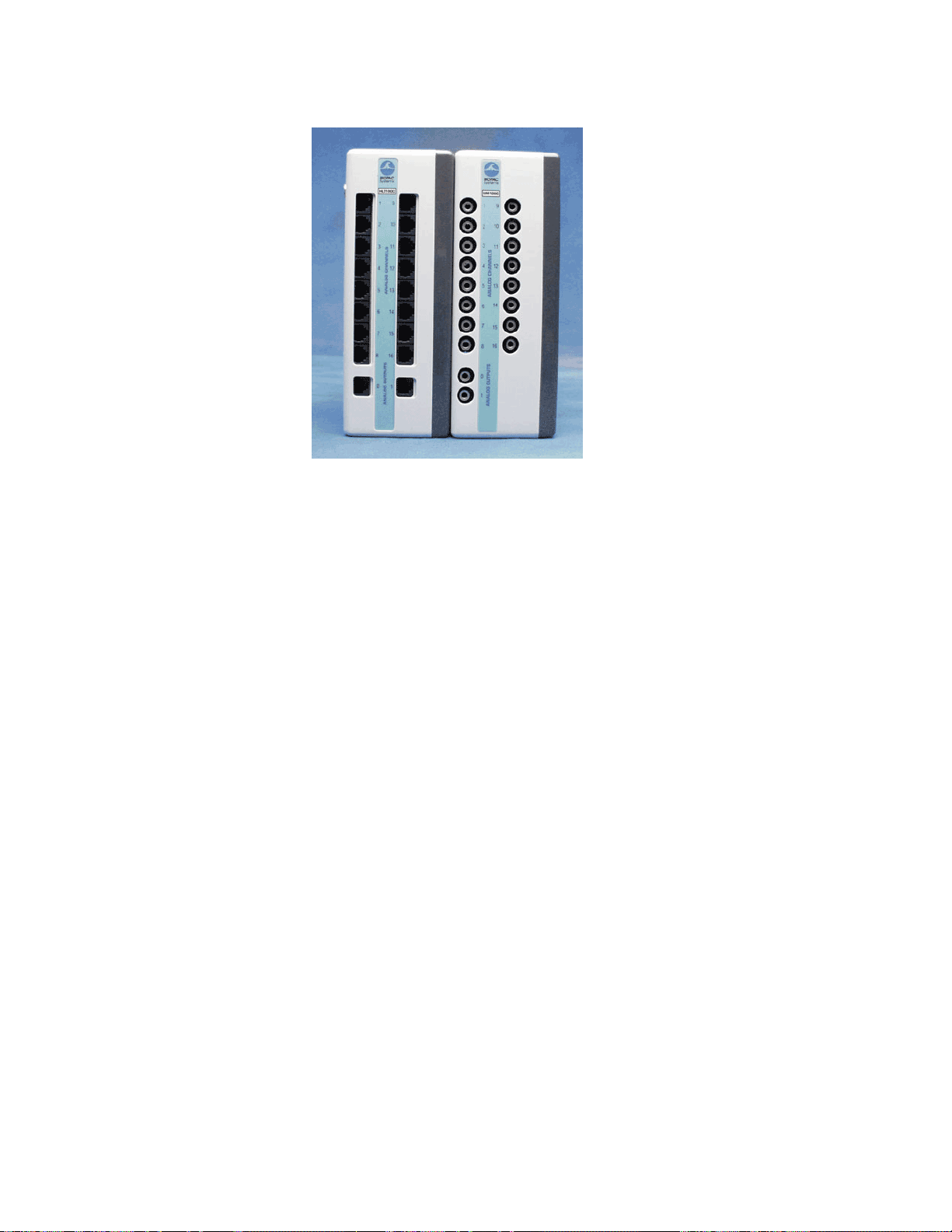
UIM100C UNIVERSAL INTERFACE MODULE
HLT100C UIM100C
The UIM100C Universal Interface Module is the interface between the MP150/100 and external
devices. Typically, the UIM100C is used to input pre-amplified signals (usually greater than +/−
0.1 volt peak-peak) and/or digital signals to the MP150/100 acquisition unit. Other signals (e.g.,
those from electrodes or transducers) connect to various signal-conditioning modules.
The Universal Interface Module (UIM100C) is designed to serve as a general-purpose interface to
most types of laboratory equipment. The UIM100C consists of sixteen 3.5 mm mini-phone jack
connectors for analog inputs, two 3.5 mm mini-phone jack connectors for analog outputs, and
screw terminals for the 16 digital lines, external trigger, and supply voltages.
The UIM100C is typically used alone to connect polygraph and chart recorder analog outputs to the
MP System. BIOPAC Systems, Inc. offers a series of cables that permit the UIM100C to connect
directly to a number of standard analog signal connectors. Most chart recorders or polygraphs have
analog signal outputs, which can be connected directly to the UIM100C.
The UIM100C allows access to 16 analog inputs and 2 analog outputs on one side, and 16 digital
input/output lines, an external trigger, and supply voltages on the other side. The UIM100C is
designed to be compatible with a variety of different input devices, including the BIOPAC series of
signal conditioning amplifiers (such as the ECG100C).
Connections between the UIM100C and the MP150/100 acquisition unit are made via two cables:
one for analog signals (with a 37-pin connector) and one for digital signals (with a 25-pin
connector). Use the 0.6-meter cables included with your system to connect the UIM100C to the
acquisition unit.
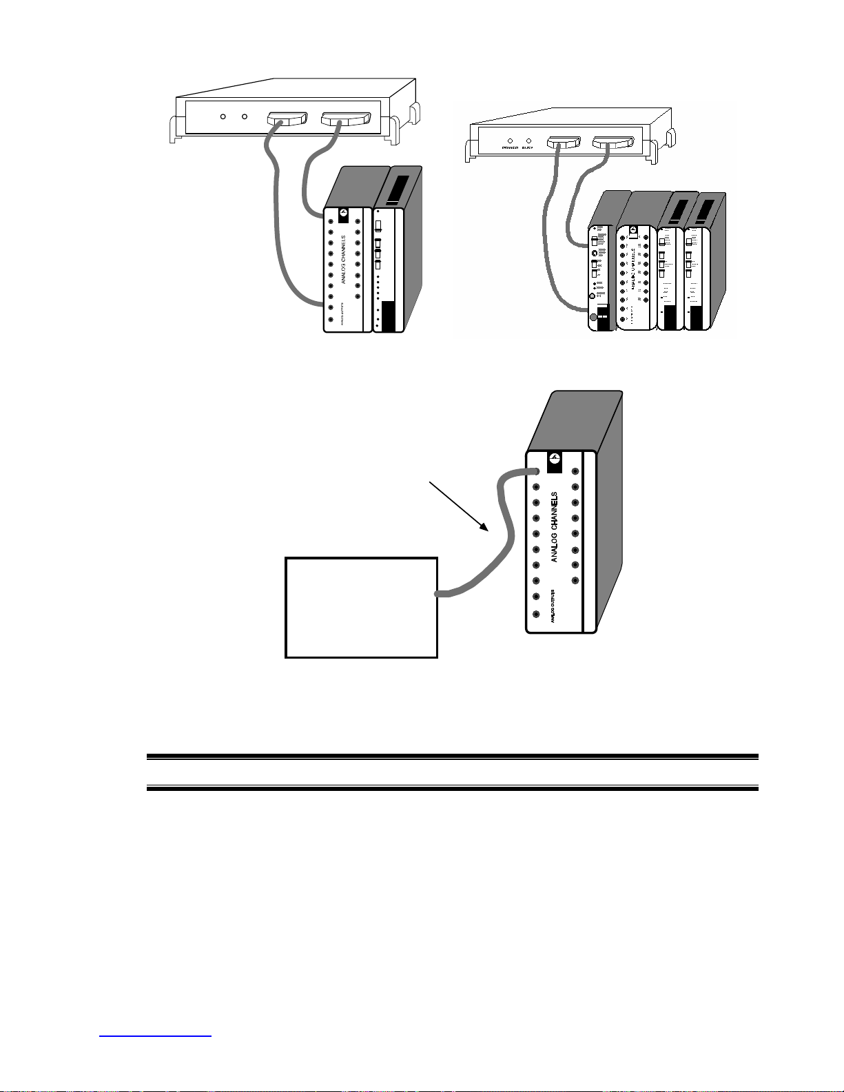
When using the Universal Interface Module (UIM100C) with other 100-Series modules, the
UIM100C is usually the first module cascaded in the chain. If using the STM100C, OXY100C or
HLT100C, the module must be plugged in on the left of the UIM100C. Up to seventeen modules
(including the UIM100C) can be snapped together, as illustrated in the following diagrams:
26 MP System Hardware Guide
Page 27
POWER BU SY
ZERO
BIOPAC
Systems
1
2
3
4
5
6
7
8
0
1
ADJ
GAIN
9
500
1000
2000
5000
10
11
ON
FILTER
12
OFF
13
14
SHIELD
VIN+
15
GND
VIN-
16
SHIELD
MP100 to UIM100C and amplifier moduleSTM100C and UIM100C and amplifier modules
Analog connection cable
(CBL100, 101, or 102)
Chart recorder
with phone jack,
RCA jack, or BNC
BIOPAC
Syste ms
1
9
2
10
3
11
4
12
13
5
6
14
15
7
8
16
0
1
connector for analog
output
Typical UIM100C to polygraph interface
When using the UIM100C, be careful not to short the “analog output” terminals together, and not to
short across any of the connectors on the “Digital” (back) side of the module.
IMPORTANT USAGE NOTE
Mains powered external laboratory equipment should be connected to an MP System through signal
isolators when the system also connects to electrodes attached to humans.
To couple external equipment to an MP System, use:
For analog signals — INISO or OUTISO isolator (with HLT100C)
For digital signals — STP100C (with UIM100C)
Contact BIOPAC for details.
www.biopac.com 27
Page 28
Analog connections
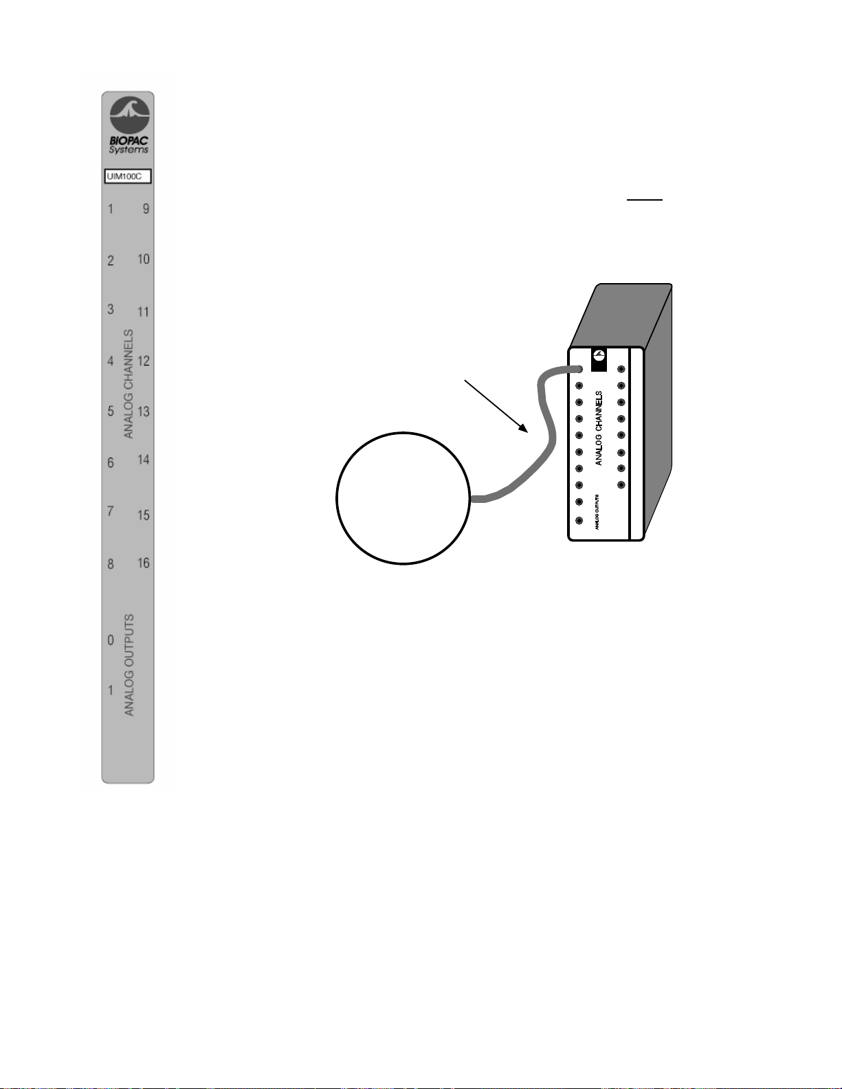
As noted, the UIM100C requires cables equipped with standard 3.5mm mini-phone plugs to
connect to analog signal sources. This type of connector is commonly available with many
different mating ends. BIOPAC Systems, Inc. carries several different types, including BNC
and phone plugs. Since the MP150/100 analog inputs are single-ended, the tip of the miniphone plug is the input and the base (shield) of the mini-phone plug is the ground (or
common).
NOTE: Make sure the cable that you route into the UIM100C is a mono
3.5 mm phone
plug.
To connect to existing equipment (such as polygraphs or chart recorders), run a cable from
the analog output terminal of the external device to the UIM100C. Since there are so many
different devices that can connect to the MP150/100 it’s impossible to cover them all.
Analog connection cable
BIOPA C
Syst ems
1
(CBL100, 101, or 102)
Transducer or
pre-amplified
electrode
9
2
10
3
11
4
12
13
5
6
14
15
7
8
16
0
1
UIM100C connected to external analog signal source
Please contact a BIOPAC Systems, Inc. applications engineer if you are not sure how to
connect the MP System to your device or if you need a special cable.
28 MP System Hardware Guide
Page 29
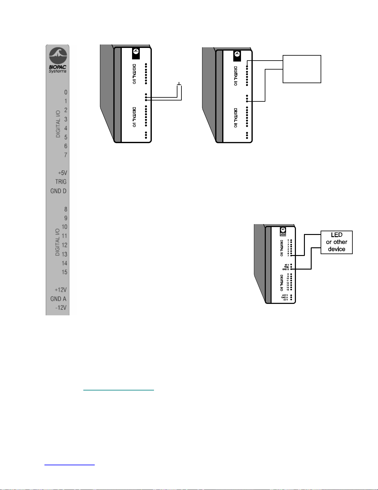
Digital connections
BIOPAC
Syst ems
GND A
TRIG
GND D
+12 V
-12 V
+5 V
0
1
2
3
4
5
6
7
8
9
10
11
12
13
14
15
Pushbutton
switch
BIOPA C
Syst ems
GND A
TRIG
GND D
+12 V
-12 V
+5 V
TTL
0
1
2
3
4
5
6
7
8
9
10
11
12
13
14
15
+
-
digital
source
Trigger connected to UIM100C MP unit to digital source connection
A digital signal has only two voltage levels: 0 Volts = binary 0 and +5 volts = binary 1.
A positive edge is a 0 to 1 transition and a negative edge is a 1 to 0 transition.
The MP150/100 digital I/O lines have internal pull-up resistors so that unconnected inputs
read “1.”
The 16 digital input/output lines on the UIM100C have screw terminals that can accept pin
plugs or bare wires, as shown above. Be careful not to short the +5, +12 V and −12 V
terminals together or to the GND A or GND D output terminal, or you may damage the
MP150/100.
The 16 digital lines are divided into two blocks, I/O 0
through 7 and I/O 8 through 15. Each block can be
programmed as either inputs or outputs. Do not connect a
digital input source to a block that is programmed as an
output.
Output devices (such as leads or an LED) can be connected
to the digital side of the UIM100C. Outputs can be
connected so that they are “
ON” either when a signal output
from the UIM100C reads 0 Volts or when a +5 V signal is
being output.
• When connecting to an LED, be sure to use a current-limiting resistor (typically
330Ω) in series with the LED.
To connect an LED so that it defaults to “
OFF” (i.e., the digital I/O reads 0), attach one lead of the output
device to the GND D terminal on the UIM100C and connect the other lead to one of the digital I/O lines
(I/O 7, for example). When configured this way, the device will be “
OFF” when I/O 7 reads 0, and “ON”
when I/O 7 reads a digital “1” (+5 Volts).
Alternatively, you can connect one of the device leads to the +5V terminal on the UIM100C and leave the
other lead connected to the digital line (e.g., I/O 7). With this setup, the device will be “
line (in this case digital I/O 7) reads 0, and “
UIM100C Specifications
OFF” when the I/O reads a digital “1” (+5 Volts).
ON” when the I/O
Analog I/O: 16 channels (front panel) – 3.5 mm phone jacks
D/A Outputs: 2 channels (front panel) – 3.5 mm phone jacks
Digital I/O: 16 channels (back panel) – screw terminals
External Trigger: 1 channel (back panel) – screw terminal
Isolated Power: ±12 V, +5 V @ 100 ma (back panel) – screw terminals
Weight: 520 g
Dimensions: 7 cm (wide) x 11 cm (deep) x 19 cm (high)
www.biopac.com 29
Page 30
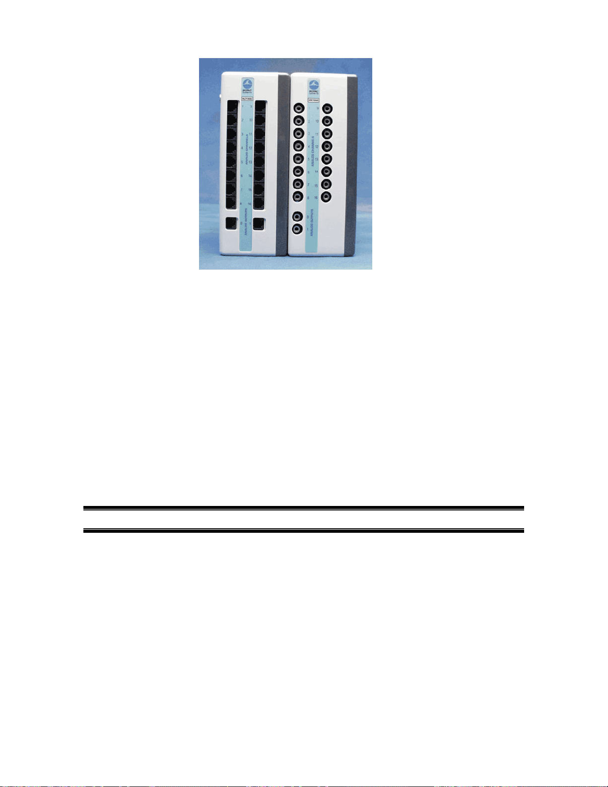
HLT100C HIGH LEVEL TRANSDUCER INTERFACE MODULE
HLT100C UIM100C
The HLT100C module is used to interface all high level output transducers to the MP System. The
HLT100C module provides 16 input and 2 output channels. The HLT100C is similar in function to
the UIM100C Universal Interface Module, but it also provides power to the transducer when
making a connection.
High level output transducers and adapters connect to the HLT100C via standard 6 pin RJ11 type
connectors. Transducers and adapters that presently require the HLT100C module are:
TSD109 C/F: Tri-axial Accelerometers
TSD111A Heel/Toe Strike Transducer
TSD115 Variable Assessment Transducer
TSD116 A/B/C: Switches and Markers
TSD150 A/B: Active Electrodes
INISO Input Signal Isolator
OUTISO Output Signal Isolator
Alternatively, the HLT100C module can be used to connect mains powered external equipment to
the MP System when the system also connects to electrodes attached to humans.
IMPORTANT USAGE NOTE
To provide the maximum in subject safety and isolation, use electrically isolated signal adapters
to connect mains powered external equipment (i.e., chart recorders, oscilloscopes, etc.) to the MP
System. Use the INISO adapter to connect to MP analog system inputs and the OUTISO adapter to
connect to analog system outputs.
30 MP System Hardware Guide
Page 31

Hardware Setup
Connect the Digital and Analog cables from the MP150 directly to the HLT100C, then connect the
UIM100C to the HLT100C. The HLT100C module must be connected on the left side of the UIM100C
module. This allows the use of other amplifier modules with the UIM100C while the HLT100C is
connected.
High level output transducers (e.g., TSD109 Tri-Axial Accelerometer) or active electrodes (e.g., TSD150A
Active Electrode) connect via the 16 analog RJ11 jacks on the front of the HLT100C. Up to 16 analog
channels can be used at the same time, as long as there are no other analog channels in use by the UIM100C
module or by other BIOPAC modules.
NOTE: If active electrodes are used, it may be necessary to attach a single ground lead to the UIM100C
via the GND A terminal on the back of the module.
IMPORTANT!
If contention exists, the channel data will be corrupted. For example, if four channels [Ch.1-4] were in use
by the UIM100C, then only 12 channels [Ch. 5-16] could be used by the HLT100C.
HLT100C Specifications
Transducer Inputs: 16 channels (front panel) – RJ11 jacks
System D/A Outputs: 2 channels (front panel) – RJ11 jacks
Isolated Power Access: ±12 V, +5 V @ 100 ma (via all RJ11 jacks)
Weight: 540 grams
Dimensions: 7 cm (wide) x 11 cm (deep) x 19 cm (high)
www.biopac.com 31
Page 32
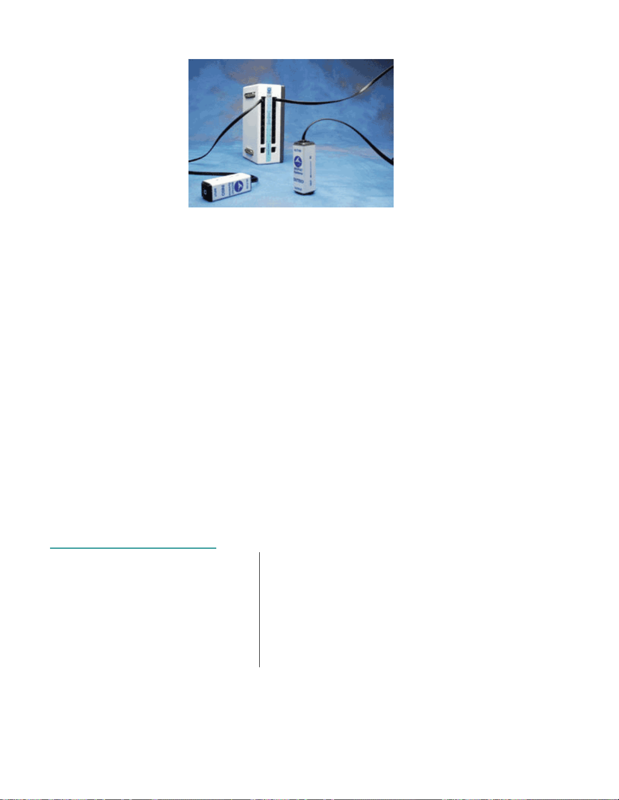
SIGNAL ISOLATORS
INISO and OUTISO shown with HLT100C
These analog signal isolators are used to connect mains powered external laboratory equipment to the MP
System when it also connects to electrodes attached to humans. Each signal isolator comes with an RJ11
cable for connection to the HLT100C module.
For digital (TTL compatible) isolation to the MP digital I/O ports, use the STP100C optical
interface (see page
If the MP System does not electrically connect to human subjects, signal connections to external
equipment can be made through the UIM100C module and the respective analog or digital
connection cable.
218).
INISO Input Signal Isolated Adapter
Use the INISO to connect external equipment outputs to MP analog input channels. The INISO plugs
directly into any of the 16 input channels on the HLT100C module and incorporates a 3.5mm phone jack
for signal input connections. Select the appropriate analog connection cable to connect to the external
equipment’s output.
OUTISO Output Signal Isolated Adapter
Use the OUTISO to connect MP analog signal outputs (amplifier and D/A) to external equipment inputs.
The OUTISO plugs directly into any of the 16 signal output channels, plus the two D/A outputs, on the
HLT100C module and incorporates a 3.5 mm phone jack for signal output connections. The OUTISO is
very useful when the biopotential amplifier output signal requires routing to external equipment while being
sampled by the MP System. Select the appropriate analog connection cable to connect to the external
equipment’s input.
INISO and OUTISO Specifications
Isolator Type: Analog
Bandwidth: DC to 50 kHz
Input/Output Range: ±10 V
Input Resistance: 200K Ω
Output Resistance: 120 Ω
Output Current: ±5 mA
Offset Voltage: ±20 mV (nominal)
Temperature Drift: 200 µV/°C (nominal)
Noise: 2.5 mV (rms)
Isolation Voltage: 1500 VDC
Isolation Capacitance: 30 pF
Connector: 3.5 mm mono phone jack
Weight: 50 g
Dimensions: 2.6 cm (high) x 2.6 cm (wide) x
7.6 cm (long)
Included Cable: 2.1 m (straight through, M/M, 6
pin, RJ11)
Interface: HLT100C—see page
30
32 MP System Hardware Guide
Page 33
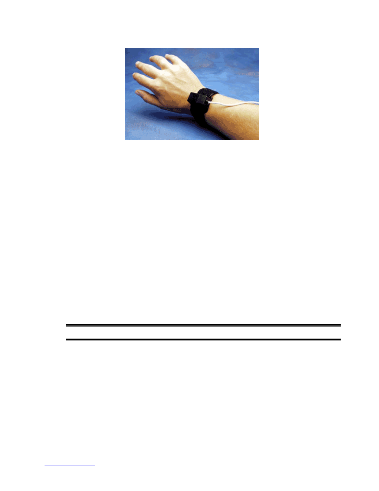
TSD109 SERIES TRI-AXIAL ACCELEROMETERS
The Tri-Axial Accelerometers are high level output transducers with an amplifier built into the
transducer, so no additional amplification is required. They connect directly to the HLT100C High
Level Transducer module to provide three outputs, which measure acceleration in the X, Y, and Z
direction simultaneously.
The TSD109C (5g) is well suited for measuring slow movements
The TSD109F (50G) is made to measure quick movements.
With the proper equipment and proper scaling parameters listed below, precise acceleration
measurements can be obtained.
Equipment
MP Starter System
HLT100C High Level Transducer Module
TSD109C Tri-Axial Accelerometer- Output +/- 5G (400 mV/G)
TSD109F Tri-Axial Accelerometer- Output +/- 50G (40 mV/G)
Hardware Setup
Connect the HLT100C to the UIM100C Universal Interface Module. The TSD109 has 3 output
connectors, 1 each for the X, Y, and Z axes. Each output connector must be connected to the
appropriate HLT100C input channel. For example the X-axis to channel 1, the Y-axis to channel 2,
and the Z-axis to channel 3.
IMPORTANT
Make sure that the channel you choose is not already assigned to any other BIOPAC module; up to
5 Accelerometers can be used with a single MP System. If contention exists, the channel data
will be corrupted.
www.biopac.com 33
Page 34
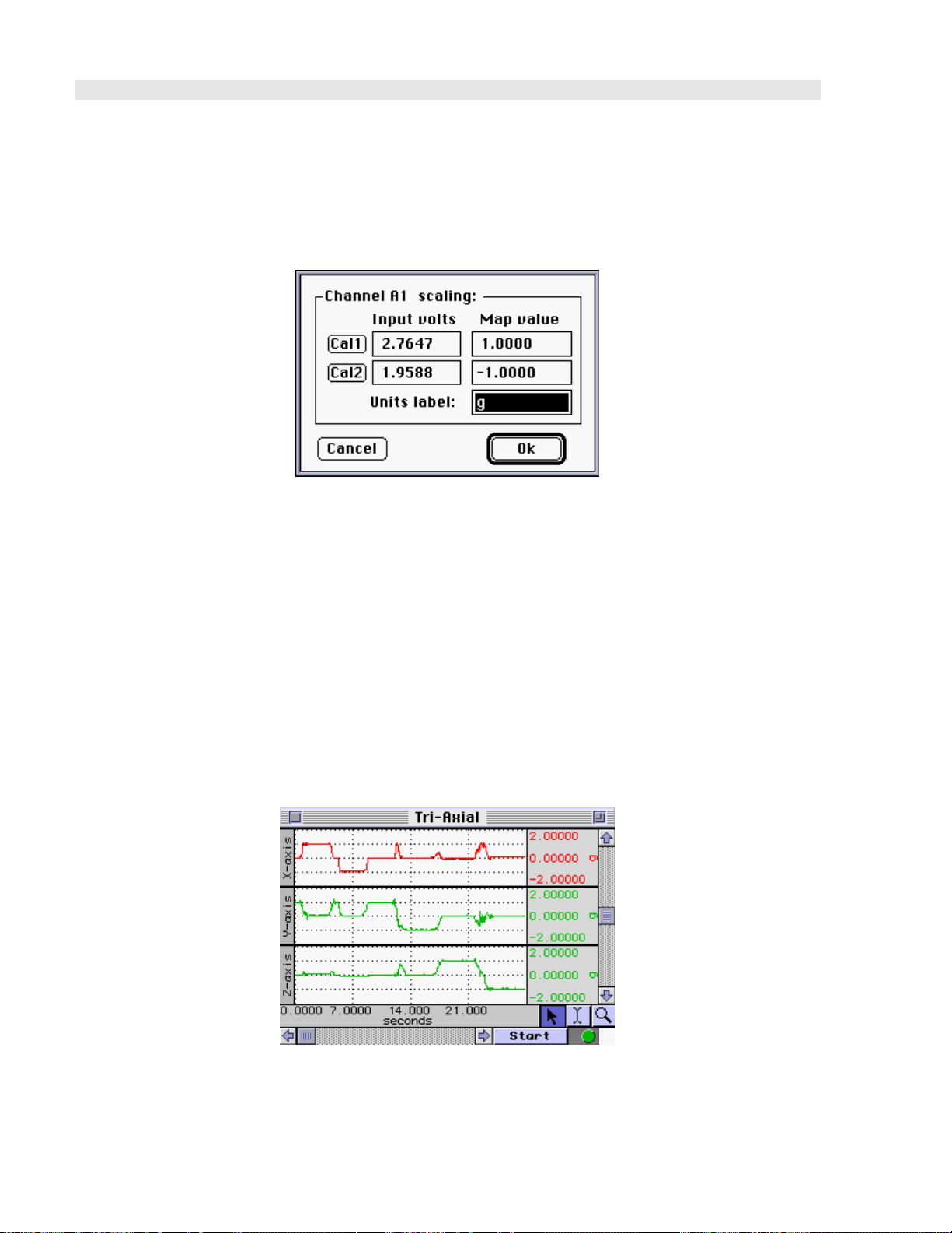
TSD109 Calibration
Software Setup
1. Select Setup Channels under the MP menu and enable 3 analog channels, one for each axis. 2. Select
Scaling (MPWSW) to generate the Scaling dialog.
3. In the Map value column, enter the scaling factors required, 1 and -1.
4. Enter “g” for the Units label, as shown.
5. Take the TSD109 and rest it in the upright position on the tabletop.
6. Calibrate the device by rotating it through 180 degrees and taking a calibration reading at each point.
To calibrate the Y-axis, set the transducer face up on a flat surface (such as a table) and click CAL1. Rotate
the transducer 180 degrees, so that it is upside down, and click the CAL2 button. This procedure must be
followed for each axis. A label on the front of the transducer displays the X and Y axes. The Z-axis rotates
from the end with the label and the end with the cable.
Testing Calibration
1. Start acquisition (for the test procedure, you should use a sample rate of 50 samples per second)
2. Rotate the TSD109 180° through each axis while continuing to acquire data.
3. Set the vertical scale to 1 and the midpoint to 0 for all channels.
4. Repeat the calibration procedure (by rotating the transducer 180°) through each axis.
5. Visually confirm the correct calibration.
This screenshot shows a TSD109 being rotated through each axis. Channel 1 (X-axis) shows the signal
moving from 1g to -1g as the transducer is rotated. Likewise, Channel 2 (Y-axis) shows the same
phenomenon as previously described. Finally, Channel 3 (Z-axis) has also been tested and the calibration
confirmed.
34 MP System Hardware Guide
Page 35

TSD109 Series Specifications
Channels: 3 – (X, Y, Z axis)
Range (Output)
TSD109C: ±5G (400 mV/G)
TSD109F: ±50G (40 mV/G)
Noise
TSD109C: 325 μG/√Hz rms
TSD109F: 2.5 mG/√Hz rms
Bandwidth: DC – 500 Hz (-3dB)
Nonlinearity: 0.2% of Full Scale
Transverse Axis Sensitivity: ±2%
Alignment Error: ±1°
Package: Compliant silicone housing
Power: +5V @ 9mA (via HLT100C)
Sterilizable: Yes (contact BIOPAC for details)
Cable Length: 3 meters
Weight: 17 grams
Dimensions: 33mm long, 28mm wide (at base), 19mm high
Interface: HLT100C—see page
TEL100C Compatibility: SS26 (5G) and SS27 (50G)—see page
30
227
www.biopac.com 35
Page 36
TSD110 PRESSURE PAD/RESPIRATION TRANSDUCER
TSD110-MRI PRESSURE PAD/RESPIRATION TRANSDUCER
The multipurpose TSD110 pressure Pad/Respiration (pneumogram) transducer can be used to:
• Noninvasively measure respiration—from a small mouse to a human.
• Measure small pressing forces (like pinching fingers together) for Parkinson’s evaluations.
• Measure human smiling (with the sensor on the cheekbone).
• Measure pulse when placed close to the heart.
• Measure spacing and pressure between teeth coming together.
The TSD110 consists of a TSD160B differential pressure transducer, RX110 pressure pad, and tubing. Use
TAPE1 or other single-sided adhesive to affix to the subject
TSD110 TSD110-MRI
Tubing Length: 1.6 m 10 m
Interface: DA100C MECMRI-DA to DA100C
Sensor type: Self-inflating pressure pad
Sensor Pad Diameter: 20 mm
Sensor Pad Thickness: 3.18 mm
Sensor Tubing Diameter: 2.2 mm
Sensor Tubing Length: 1 m
Sensor Tubing ID: 1.6 mm
Tubing Termination: Luer male
RX110 Pressure Pad
The RX110 pressure pad can be used many times, but may eventually need to be replaced because it is
a sensitive sensor and may become damaged with rough use.
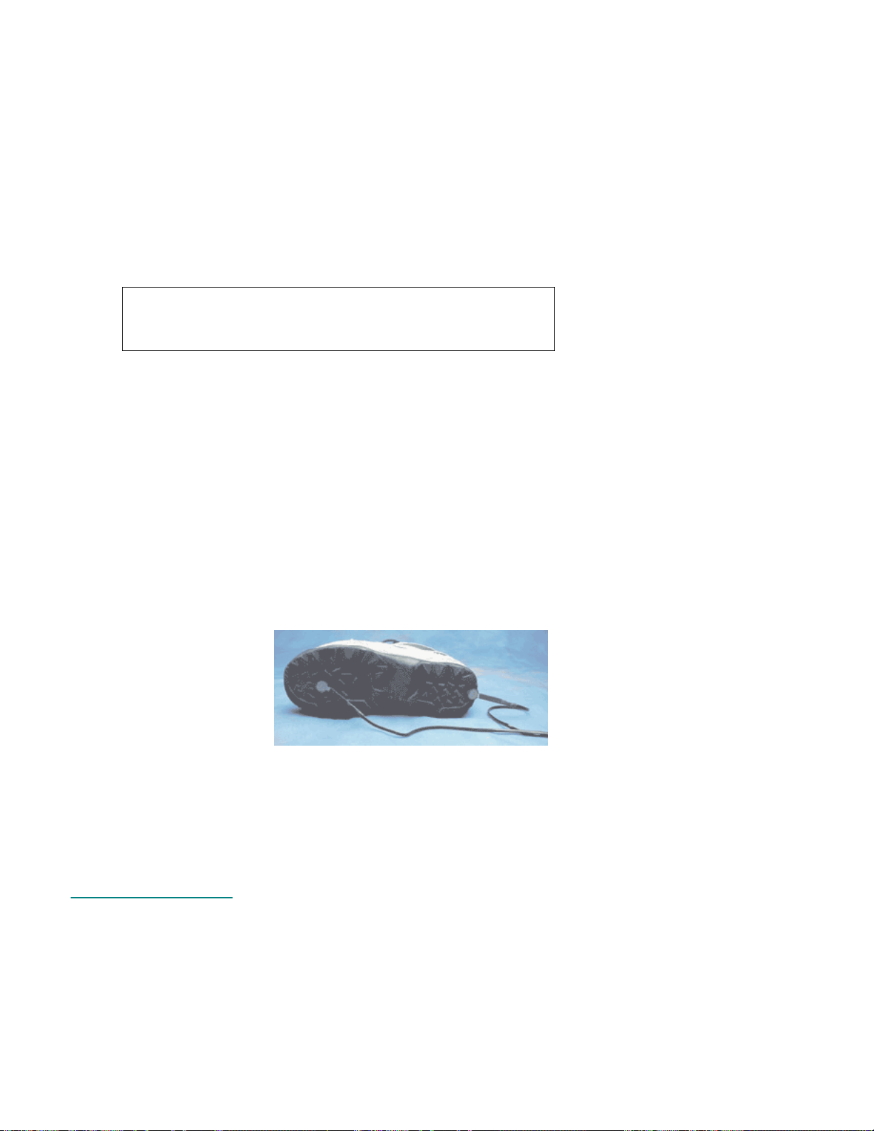
TSD111A HEEL/TOE STRIKE TRANSDUCER
Each TSD111A heel/toe strike transducer incorporates two force sensitive resistor (FSR) sensors designed
for attachment to the sole of a shoe. Typically, one FSR is placed (taped) under the heel and the other is
placed under the toe. The FSRs indicate the precise moment of pressure placed on the heel and toe as the
subject walks. The heel/toe strike data is encoded onto a single analog channel; the heel strike results in a [1V] signal and the toe strike results in a [+1V] signal. If heel and toe strike timing is required for both feet,
two TSD111A transducers are required. The TSD111A comes equipped with a 7.6-meter cable and is
designed for direct connection to the HLT100C module.
TSD111A Specifications
Nominal Output Range: -1 to +1 V
Nominal Contact Force: 200g to indicate heel/toe strike
Attachment: tape (use TAPE1, TAPE2, or vinyl, electrical or duct tape)
FSR Active Area: 12.7 mm (dia)
FSR Dimensions: 18.3 mm (dia) x 0.36 mm (thick) and 30 cm pigtail lead
Cable Length: 7.6 m
Interface: HLT100C—see page
TEL100C compatibility: SS28A—see page
36 MP System Hardware Guide
30
227
Page 37
RX111 Heel/Toe Strike Sensor
Replacement strike sensor for Heel/Toe Strike transducers:
• TSD111A (research systems)
• SS28A (telemetry systems)
Note Heel/Toe Strike Transducers without the “A” suffix in the part number (TSD111, SS28) do not
have a replaceable sensor. Check the part number or check the cable for a removable sensor
connector before ordering this replacement.
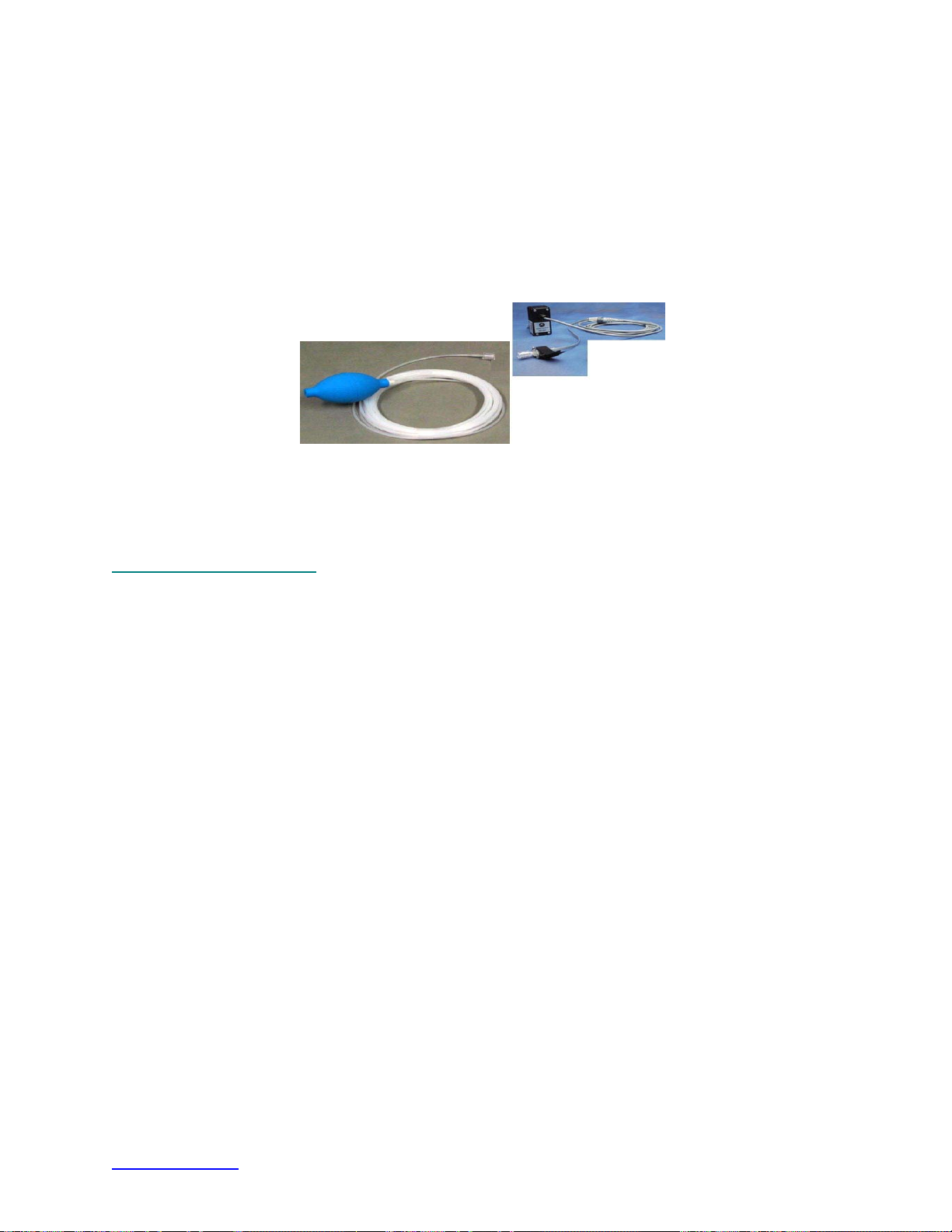
TSD114-MRI RESPONSE/HAND FORCE TRANSDUCER FOR MRI
The TSD114-MRI consists of a pump bulb (RXPUMPBULB), pressure transducer (TSD104A equivalent,
terminated in DSUB9), and tubing (AFT30-XL). Subjects can squeeze the bulb by hand or apply pressure
via foot, thigh, etc. to indicate a response while in the MRI.
• Requires MECMRI-DA for proper operation.
TSD114-MRI Specifications
Pump Bulb: Rubber bulb with endcap for connection to the pressure transducer
Transducer: Equivalent to TSD104A
Tubing: See AFT30-XL
www.biopac.com 37
Page 38
TSD115 VARIABLE ASSESSMENT TRANSDUCER
TSD115-MRI VARIABLE ASSESSMENT TRANSDUCER FOR MRI
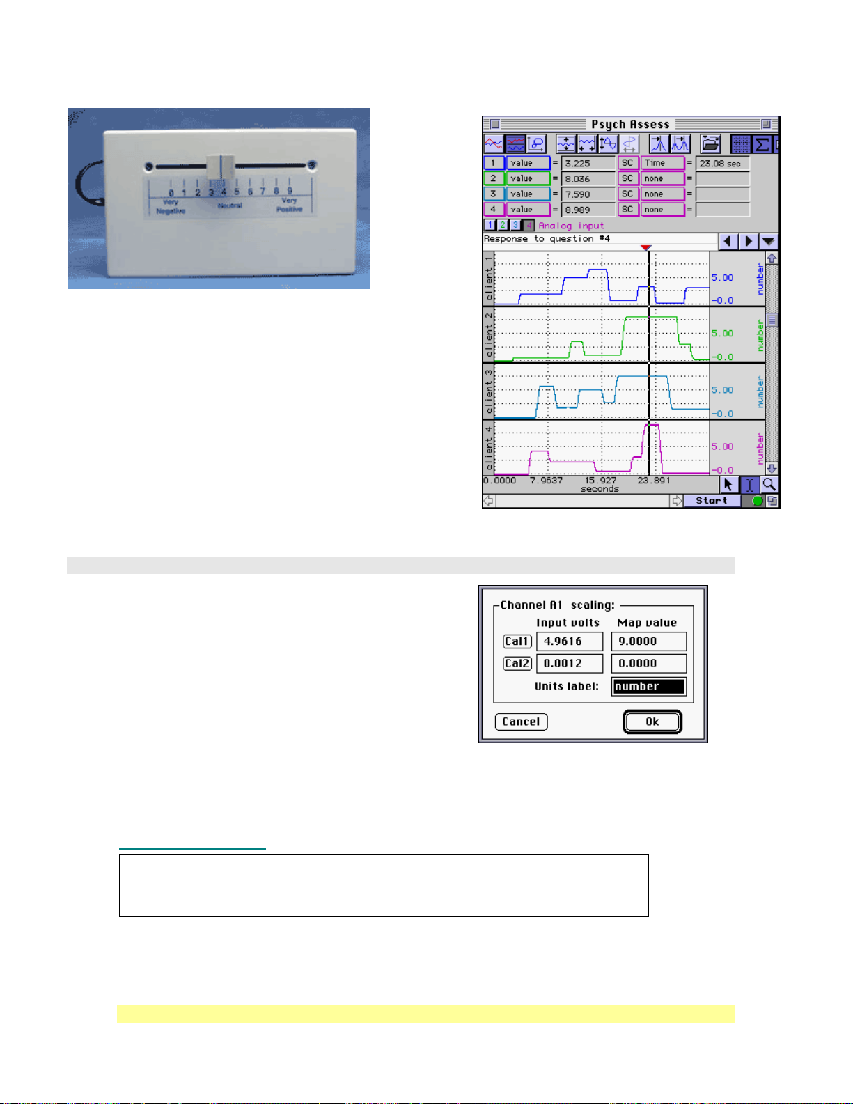
The TSD115 incorporates a slide control with graduated scale
that allows the user to gauge their subjective response to a
variety of different stimuli. Multiple TSD115 transducers can be
used simultaneously allowing several people to answer the same
question or otherwise respond to stimuli. The transducer is
lightweight and fits easily into the subject’s hand or lap. The
TSD115 comes equipped with a 7.6-meter cable and is designed
for direct connection to the HLT100C module.
This graph shows a measurement that identifies the responses
(on a scale from 0 to 9) of the four clients to a particular
question. In this case, at 23.08 seconds into the recording, the
responses to question four were:
Client 1: 3.225
Client 2: 8.036 Client 4: 8.989
TSD115 Calibration
1. Generate the Scaling dialog for the first selected
channel.
2. Slide the horizontal indicator all the way to the right
side of the TSD115. (This reports the highest output for
the TSD115, a value close to +5.0 volts.)
3. Click on the Cal1 button to assign this value to “9.”
(This directs the system to collect the exact value output
by the TSD115 when it’s set to any specific indicator
position.)
4. Slide the horizontal indicator all the way to the left on the TSD115. (This reports the lowest output
for the TSD115, a value close to 0.0 volts.)
5. Click on the Cal2 button to assign this value to “0.”
6. Select the next channel and repeat this procedure for the remaining channels.
TSD115 Specifications
Client 3: 7.590
Tubing Length: 7.6 m 8 m
Interface: HLT100C—see page 30 MECMRI-HLT to HLT100C
Scale Output Range: 0-5 V
Scale Resolution: Infinitely adjustable
Slide Control Length: 10 cm
Dimensions: 4 cm (high) x 11 cm (deep) x 19 cm (wide)
Weight: 230 g
See also: Application Note #AH186 – Psychological Assessment (TSD115)
38 MP System Hardware Guide
TSD115 TSD115-MRI
Page 39
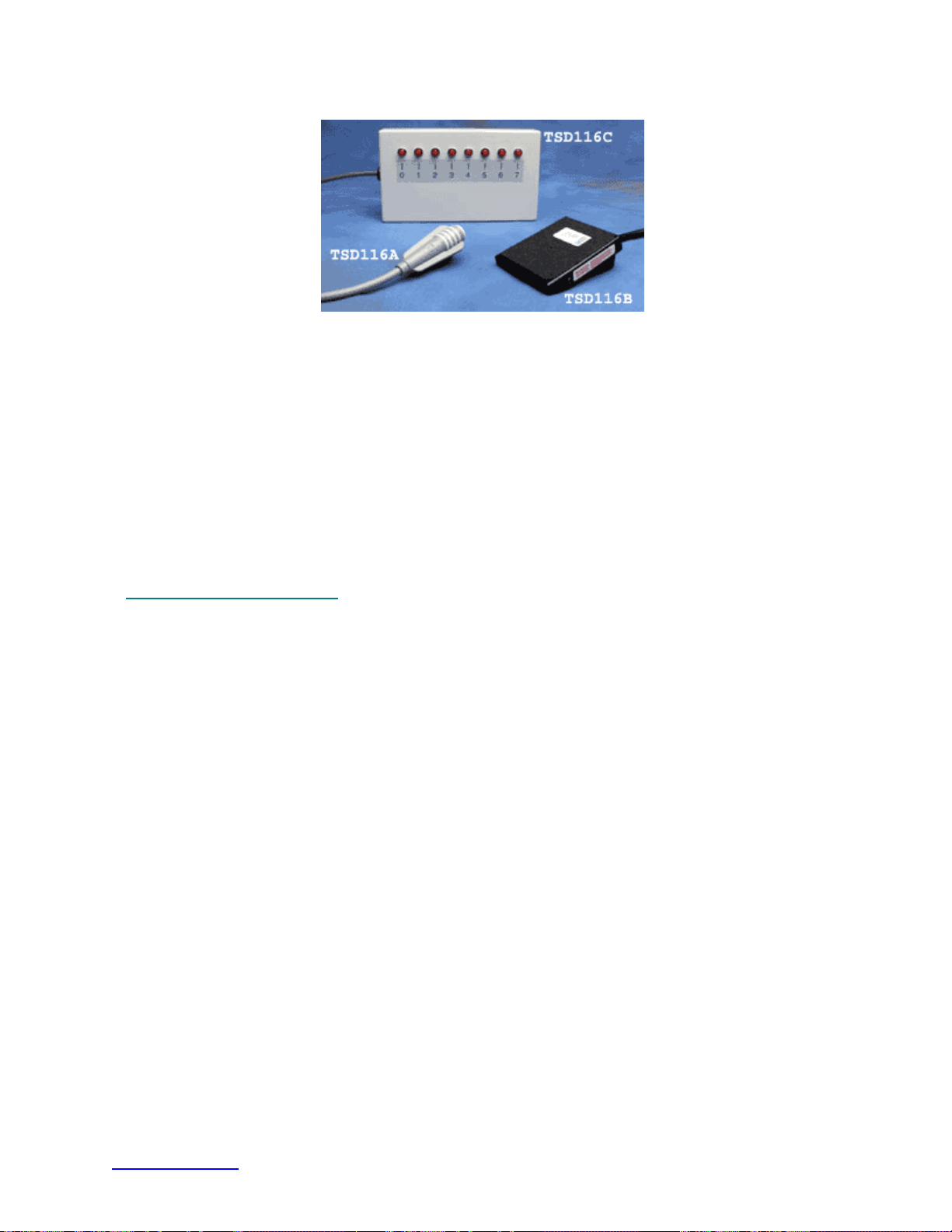
TSD116 SERIES SWITCHES AND MARKERS
The TSD116 series is used for externally triggering data acquisition, remote event marking, or
psychophysiological response tests. The switches connect to the UIM100C digital I/O ports and can be
monitored as input channels. The TSD116 series incorporate momentary ON operation (switch is ON only
when pressed).
TSD116A — single channel hand switch
TSD116B — single channel foot switch
TSD116C — compact 8-channel digital marker
The TSD116C allows the user to independently mark events, or provide responses, on up to eight channels
simultaneously. Because digital channels can be interleaved with analog channels, when using
AcqKnowledge, it’s easy to assign separate digital channels as event markers for individual analog input
channels.
TSD116 Series Specifications
Switch Type: Pushbutton: (ON) – OFF
Dimensions
TSD116A: 19mm (dia) x 63mm (long)
TSD116B: 69mm (wide) x 90mm (long) x 26mm (high)
TSD116C: 19cm (wide) x 11cm (deep) x 4cm (high)
Cable Length
TSD116A: 1.8 meters
TSD116B: 1.8 meters
TSD116C: 3 meters
Connector Type:
TSD116A: 2mm pin plugs
TSD116B: 2mm pin plugs
TSD116C: Stripped and tinned wires
Interface: UIM100C
TEL100C Compatibility: SS10 Hand switch—see page
227
www.biopac.com 39
Page 40

TSD150 SERIES ACTIVE ELECTRODE
TSD150A — 35 mm TSD150B — 20 mm
TSD150 Active Electrodes are available in three configurations; the difference is the spacing
between the stainless steel pads of the surface electrode. The surface electrode pads of the
TSD150A and TSD150B have a diameter of 11.4 mm.
Note: GROUND MUST BE USED — Unlike most active electrodes, TSD150 series active
electrodes have only two stainless steel disks attached to an electrode case. The third disk,
commonly centered between the two, is not necessary. In place of this third disk, a separate
ground electrode is used. The LEAD110A is typically used as the ground electrode, and is
inserted into the GND A terminal at the rear of the UIM100C. If one or more active
electrodes are used on a single subject, only one Ground lead (LEAD110A) is required to
act as Ground reference for all the active electrodes.
TSD150A/B ACTIVE ELECTRODES –35 MM, 20 MM
TSD150A and TSD150B may be used as a surface electrode or as a fine wire electrode. Conversion
of the surface to fine wire electrode is easily accomplished by replacing the stainless steel pads with
screw-springs that connect to the internal amplifier.
Conversion from Surface Electrode to Fine Wire Electrode System
To convert the active electrode from a surface electrode to a fine wire electrode system, the
stainless steel pads of the surface electrode must be unscrewed from the active electrode case. To
accomplish this task:
1) Grasp the stainless steel pads and rotate them counterclockwise until they are disconnected
from the case.
2) Screw the screw-spring combinations (fine wire electrode attachment) into the holes left by
the removal of the stainless steel pads.
3) Attach the active electrode case (using tape or an elastic strap) to the limb of the subject, near
the insertion site of the fine wire electrodes.
4) Gently bend the springs and place one fine wire electrode in the gap formed by bending the
spring. Allow the spring to return to its upright position.
5) Repeat this procedure for the other fine wire electrode.
Note: If the wire-spring contact does not provide a good EMG signal, it may be necessary to rub the
fine wire electrode with an emery cloth to remove the insulation prior to placing the wire in
the spring.
To convert the system back to a surface electrode system, simply unscrew the screw-spring
combinations, place them in a secure place and re-screw the stainless steel electrode pads into the
electrode case.
40 MP System Hardware Guide
Page 41

Operation
1) Attach the active electrode to the subject, with pads to the skin surface; use surgical tape (TAPE1)
or an elastic strap. The active electrode requires good skin surface contact, so to obtain the best
readings, you should select an area where skin surface is free of hair and/or lesions and abrade the
skin slightly with the ELPAD.
2) Plug the active electrode into the desired channel (1-16) of the HLT100C module.
IMPORTANT! Make sure that the channel you choose is not already assigned to any other
BIOPAC module; up to 16 active electrodes can be used with a single MP
System. If contention exists, the channel data will be corrupted.
3) After inserting the active electrode into the HLT100C module and attaching the active electrode to
the subject, you will still need to attach a Ground electrode to the subject. The Ground electrode
will act as reference for 1 to 16 active electrodes. The LEAD110A, 3-meter, unshielded electrode
lead is recommended for this purpose. The LEAD110A will connect directly to any standard snap
surface electrode (like the EL503). The surface electrode can be placed at any point on the subject,
and performance is optimal when the electrode makes good contact with the skin surface.
4) The free end of the LEAD110A is inserted directly to the GND A terminal on the back of the
UIM100C. To insert the LEAD110A into the GND A terminal, use a small screwdriver to back out
the terminal locking screw, insert the LEAD110A 2 mm pin plug into the terminal opening and
then tighten down the locking screw.
5) At this point, the active electrode is ready for data collection. Set up the active electrode Scaling in
AcqKnowledge, by setting the MAP values to a factor of the default value divided by330. See the
“MP System Guide” for more information on channel scaling. The recommended sampling rate for
the MP System is 2000Hz on each active electrode channel.
TSD150A/B Calibration
The TSD150 series does not require calibration.
TSD150A/B Active Electrode Specifications
Recommended Sample Rate: Best: 2000Hz, Minimum: 1000Hz
Gain: 350 (nominal)
Input Impedance: 100 MΩ
CMRR: 95 dB (Nominal)
3 dB Bandwidth: 12Hz – 500Hz
Cable: 3 meters, lightweight, shielded
Electrode Spacing
TSD150A: Wide — 35 mm
TSD150B: Narrow — 20 mm
Stainless steel disk diameter: 11.4 mm
Fine Wire Attachment: Screw springs
Ground Lead: Requires LEAD110A for proper operation (one per subject)
Dimensions: 17.4mm wide x 51 mm long x 6.4 mm thick
Weight: 9.5 grams
Interface: HLT100C—see page
See also: LEAD110A
TAPE1 / TAPE2
30
www.biopac.com 41
Page 42
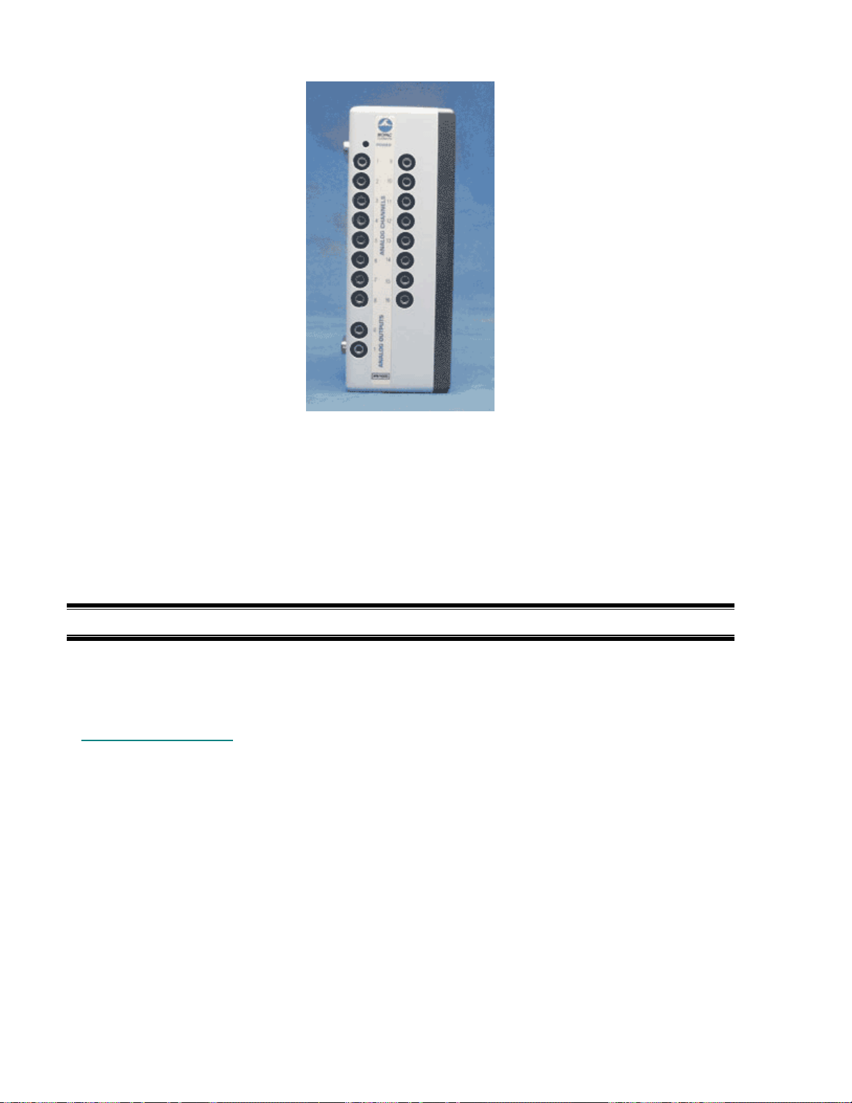
IPS100C ISOLATED POWER SUPPLY MODULE
The IPS100C is used to operate 100-series amplifier modules independent of an MP data acquisition unit.
The IPS100C module couples the 100-series amplifier outputs directly to any other data acquisition system,
oscilloscope or chart recorder. Amplifier modules snap onto the side of the IPS100C to receive the
necessary isolated power and to direct the modules’ output to the front panel of the IPS100C. The IPS100C
allows users to operate up to 16 amplifiers on a stand-alone basis. The analog channel outputs are provided
via 3.5mm phone jacks on the front panel. The IPS100C is generally used with animal or tissue
preparations. When collecting data from electrodes attached to humans, use the HLT100C module with
INISO and OUTISO adapters to couple signals to external equipment.
Includes In-line Transformer (AC100A) and USA or EURO power cord.
IMPORTANT USAGE NOTE
Do not use the IPS100C with an MP based system. For a fully isolated recording system using the IPS100C,
couple signal inputs and outputs through the HLT100C module and INISO and OUTISO adapters,
respectively. Contact BIOPAC for details.
IPS100C Specifications
Amplifier Output Access: 16 channels (front panel) – 3.5mm phone jacks
Isolated Power Access: ±12V, +5V @ 100 ma (back panel) – screw terminals
Weight: 610 grams
Dimensions: 7cm (wide) x 11cm (deep) x 19cm (high)
Power Source: 12VDC @ 1 amp (uses AC100A transformer)
42 MP System Hardware Guide
Page 43
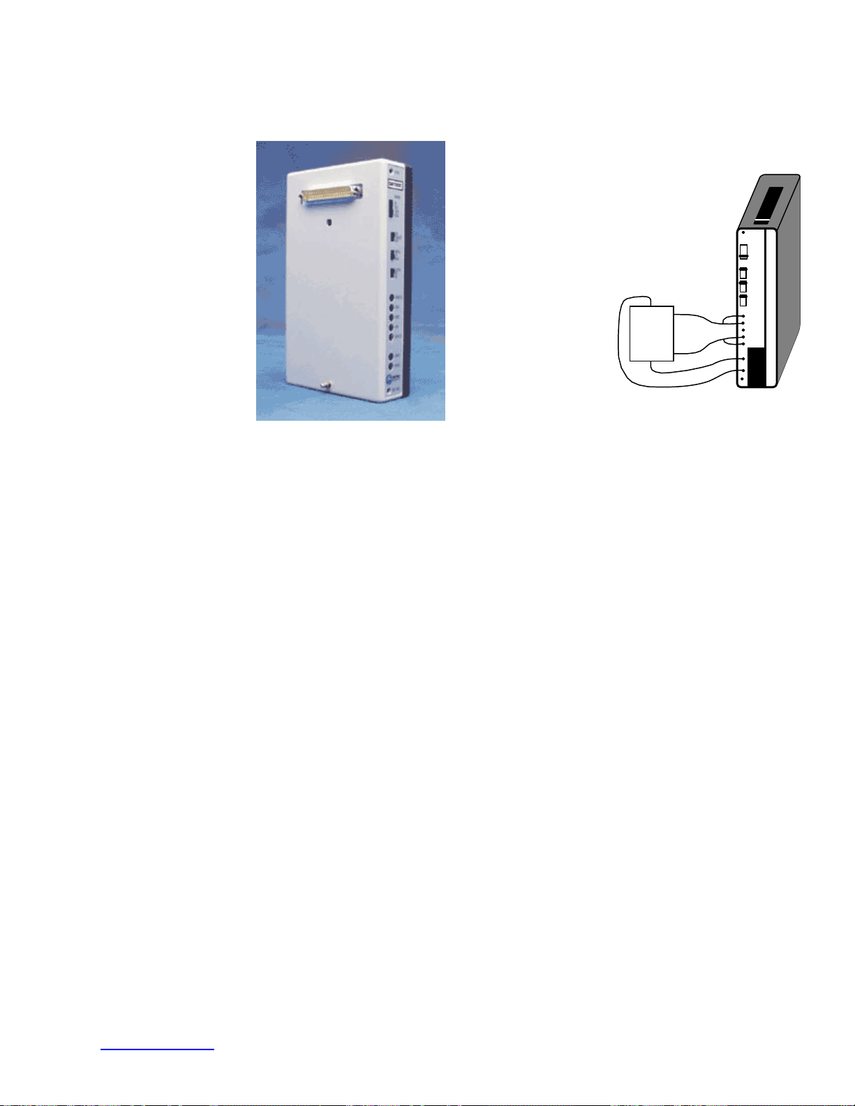
Chapter 3 General Purpose Transducer Amplifier Module
DA100C – DIFFERENTIAL AMPLIFIER MODULE
V+
BRIDGE
V-
The differential amplifier module (DA100C) is a general purpose, single channel, differential amplifier. The
DA100C is designed for use in the following measurement applications:
Blood pressure (hemodynamics) Physiological sounds
Displacement (linear or angular) Temperature
Muscle strain or force (pharmacology) Humidity
ZERO
ADJ
GAIN
500
1000
2000
5000
ON
FILTER
OFF
AC
DC
SHIELD
VIN+
GND
VIN-
SHIELD
DA100
VREF1
VREF2
REF
ADJ
The DA100C has one differential input linear amplifier with adjustable offset and gain. The DA100C is
used to amplify low-level signals from a variety of sources. The DA100C has built-in excitation capability,
so it can work directly with many different types of transducers, such as:
Pressure transducers Piezo sensors
Strain gauges Wheatstone bridges
Accelerometers Photocells
Microphones Thermistors
Electrogoniometers
Compatible BIOPAC Transducers are:
T
RANSDUCER TYPE TRANSDUCER TYPE
TSD104A Precision Pressure TSD121C Hand Dynamometer
TSD105A Variable Range Force TSD125 Series Fixed Range Force
TSD107B High Flow Pneumotach TSD127 Low Flow Pneumotach
TSD108 Physiological Microphone TSD130 Series Goniometers & Torsiometers
TSD117 Medium Flow Pneumotach TSD137 Series Very Low Flow Pneumotach
TSD120 Noninvasive BP cuff TSD160 Series Differential Pressure
If the input signal is applied differentially between the VIN+ and VIN- inputs, the Input Signal Range can be
centered on any voltage from -10 V to +10 V with respect to GND. If the signal is applied to a single input (with
the other input grounded), then that signal can range over the selected Input Signal (pk- pk) with respect to GND.
The DA100C can be used to directly connect existing transducers. The DA100C can be outfitted with connector
assemblies for easy interfacing to a variety of “off the shelf” pressure transducers, force gauges, and strain gauges.
www.biopac.com 43
Page 44
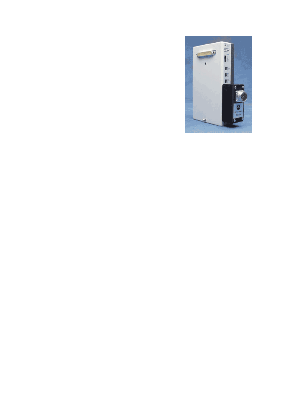
These transducer connector interfaces (TCIs) have pin plugs on one side and the transducer mating connector on
the other. The following TCIs are available. Or you can use the TCI Kit to make a custom adapter.
TCI100 Grass/Astromed transducers – 6 pin
TCI101 Beckman transducers – 5 pin
TCI102 World Precision Instrument transducers – 8 pin
TCI103 Lafayette Instrument transducers – 9 pin
TCI104 Honeywell transducers – 6 pin
TCI105 Modular phone jack connector – 4 pin
TCI106 Beckman transducers – 12 pin
TCI107 Nihon Koden transducers – 5 pin
TCI108 Narco transducers – 7 pin
TCI109 Fukuda transducers – 8 pin
TCI110 Gould transducers – 12 pin
TCI111 Liquid metal transducers – two 2mm sockets
TCI112 Hokanson transducers – 4 pin
TCI113 Hugo Sachs/Harvard Apparatus — 6 pin
TCI114 “SS” BSL Series Transducers
Important Notes
Set REF ADJ pot. On the DA100C: VREF1 to +5V, VREF2 to –5V
•
• The following SS Series Transducers require multiple channel inputs and therefore
require a corresponding number of TCI114 with a DA100C each:
o SS20L and SS21L Twin-axis Goniometers (2 channels)
o SS26L and SS27L Tri-Axial Accelerometers (3 channels)
o SS31L Noninvasive Cardiac Output Sensor (2 channels)
• The TCI114 interface is designed for SS Series Transducers only
o SS1L, SS1LA, SS2L, or SS29L Electrode Leads and Adapters – not
recommended: signal may be obtained but quality may be impaired.
o SS53L, SS54L, and SS55L Digital Switches – not supported: digital interface
required; use
TSD116 Series Switches & Markers.
o SS58L Low-Voltage Stimulator – not supported.
o OUT1 Headphones – not supported
TCIPPG1 Geer to PPG100C only — 7 pin
Voltage References
The DA100C has two adjustable voltage sources (VREF1 and VREF2) for activating passive sensors like
pressure transducers, strain gauges, thermistors and photocells. The references can be set anywhere from -
5.0 to +5.0 V. GND is at 0 V. VREF1 and VREF2 track each other with opposite polarity, thus a maximum
differential of 10 V is obtainable for driving external transducers. For example, if VREF1 is set to +1.0 V
(with respect to GND), then VREF2 will automatically be set to –1.0 V.
The references can be adjusted using the REF ADJ potentiometer near the bottom of the module. The
voltage references can handle up to 20 mA sourcing or sinking to each other or GND. Pay close attention to
your sensor drive requirements so as to minimize overall current consumption.
44 MP System Hardware Guide
Page 45

Frequency Response Characteristics
Use the 10Hz LP lowpass filter for connecting the DA100C to most pressure, force, and strain transducers (i.e.,
TSD104A, TSD105A, TSD120, TSD121C, TSD125 Series, and TSD130 Series).
Use the 300Hz LP lowpass filter for connecting the DA100C to devices with higher frequency output signals (i.e.,
TSD107B, TSD108, TSD117).
Use the 5,000Hz LP lowpass filter for connecting the DA100C to devices with the highest frequency signals, such
as microphones and clamp signals (patch, voltage or current).
See the sample frequency response plots beginning on page
241: 10Hz LP, 300Hz LP, 5000Hz LP
DA100C Calibration
A. Reference calibration
B. Amplifier gain calibration
C. Transducer calibration if applying physical variable
D. Transducer calibration if not applying physical variable
A. Reference Calibration
The REFCAL (see page 47) is used to check the reference voltage of the DA100C. The ref voltage is used to
provide excitation to passive transducers.
B. Amplifier Gain Calibration
Use the CBLCAL/C.
C. Transducer Calibration if applying physical variable
1. Plug transducer it into the DA100C.
2. Set the gain switch on the DA100C to the desired level.
3. Apply the physical variable to the transducer on the low end of your expected range.
4. Press on Cal 1 in the scaling window in AcqKnowledge.
5. Apply the physical variable to the transducer on the high end of your expected range.
6. Press on Cal 2 in the scaling window in AcqKnowledge.
7. Review the Input Voltage differential (provided in the scaling window as a consequence of pressing cal
1/cal2) and adjust if necessary
If the Input Voltage differential is less than +/- 100 mV it may be appropriate to increase the gain
setting on the DA100C.
If either Input Voltage signal is higher than 9.9V or less than –9.9V, then reduce the gain setting on the
DA100C.
If you adjust the Gain switch setting on the DA100C, then you will need to repeat steps 3-7.
The physical variable for calibration varies based on the transducer type. See the appropriate transducer
specification for details:
RANSDUCER TYPE TRANSDUCER TYPE
T
TSD104A Precision Pressure TSD121C Hand Dynamometer
TSD105A Variable Range Force TSD125 Series Fixed Range Force
TSD107B High Flow Pneumotach TSD127 Low Flow Pneumotach
TSD108 Physiological Microphone TSD130 Series Goniometers & Torsiometers
TSD117 Medium Flow Pneumotach TSD137 Series Very Low Flow Pneumotach
TSD120 Noninvasive BP cuff TSD160 Series Differential Pressure
www.biopac.com 45
Page 46

D. Transducer Calibration if not applying physical variable
Use this procedure if you can’t easily generate the required physical variable changes in order to calibrate the
transducer.
1. Calculate the de-normalized calibration factor, VY.
a) Note the factory calibration constant (generally listed as “Output” in the transducer
specifications), expressed in the form of voltage/physical variable (V/P),
b) Multiply V/P by the reference voltage (RV) of the DA100C (2 V factory preset).
c) Multiply the result [(V/P) * RV] by the Gain switch setting value on the DA100C.
2. Plug the transducer into the DA100C.
3. Press Cal 1 …this will generate VB in the Input Voltage box
4. Enter the ambient physical value in the Cal 1 Map/Scale window
5. Enter Cal 2 Input Voltage as V
Y+VB
6. Enter the ambient + delta physical value in the Cal 2 Map/Scale window
DA100C Specifications
Gain: 50, 200, 1000, 5000
Output Range: ±10V (analog)
Frequency Response
Low Pass Filter: 10Hz, 300Hz, 5000Hz
High Pass Filter: DC, 0.05Hz
Input Voltage (max): ±200mV (protected)
Noise Voltage: 0.11µV rms – (0.05-10Hz)
Temperature Drift: 0.3µV/°C
Z (Differential input): 2MΩ
CMRR: 90dB min
CMIV—referenced to
Amplifier ground: ±10V
Mains ground: ±1500 VDC
Voltage Reference: -10 to +10V infinitely adjustable @ 20ma (max)
( preset to 2 volts excitation)
Signal Source: Variety of transducers
Input Voltage Range Gain
Vin (mV)
50 ±200
200 ±50
1000 ±10
5000 ±2
Weight: 350 grams
Dimensions: 4cm (wide) x 11cm (deep) x 19cm (high)
46 MP System Hardware Guide
Page 47
REFCAL REFERENCE CALIBRATOR FOR THE DA100C
The REFCAL is used to check the reference voltage of the DA100C. It connects to the DA100C and displays
the reference voltage as an analog input signal. This makes it very easy to adjust the reference voltage of the
DA100C to suit your transducer.
The REFCAL connects the VREF1 and VREF2 voltage reference outputs directly to the DA100C inputs via a
precision attenuator of value (1/50). When using the REFCAL to set the DA100C references, the DA100C
should be set to DC with a gain of 50.
The voltage output on the selected channel of the DA100C will be the voltage difference between VREF1 and
VRREF2:
V
CBLCAL Calibration Cable for the DA100C
Use the CBLCAL to verify the signal calibration of the DA100C. This cable (1.8m) connects between the
DA100C input and the UIM100C D/A output 0 or 1. To verify the DA100C’s frequency response and gain
settings, create a stimulus signal with AcqKnowledge and monitor the DA100C’s output. The CBLCAL
incorporates a precision 1/1000 signal attenuator.
See also: Application Note #AH102 — Biopotential Amplifier Testing using CBLCAL
OUT
= V
REF1
– V
REF2
www.biopac.com 47
Page 48
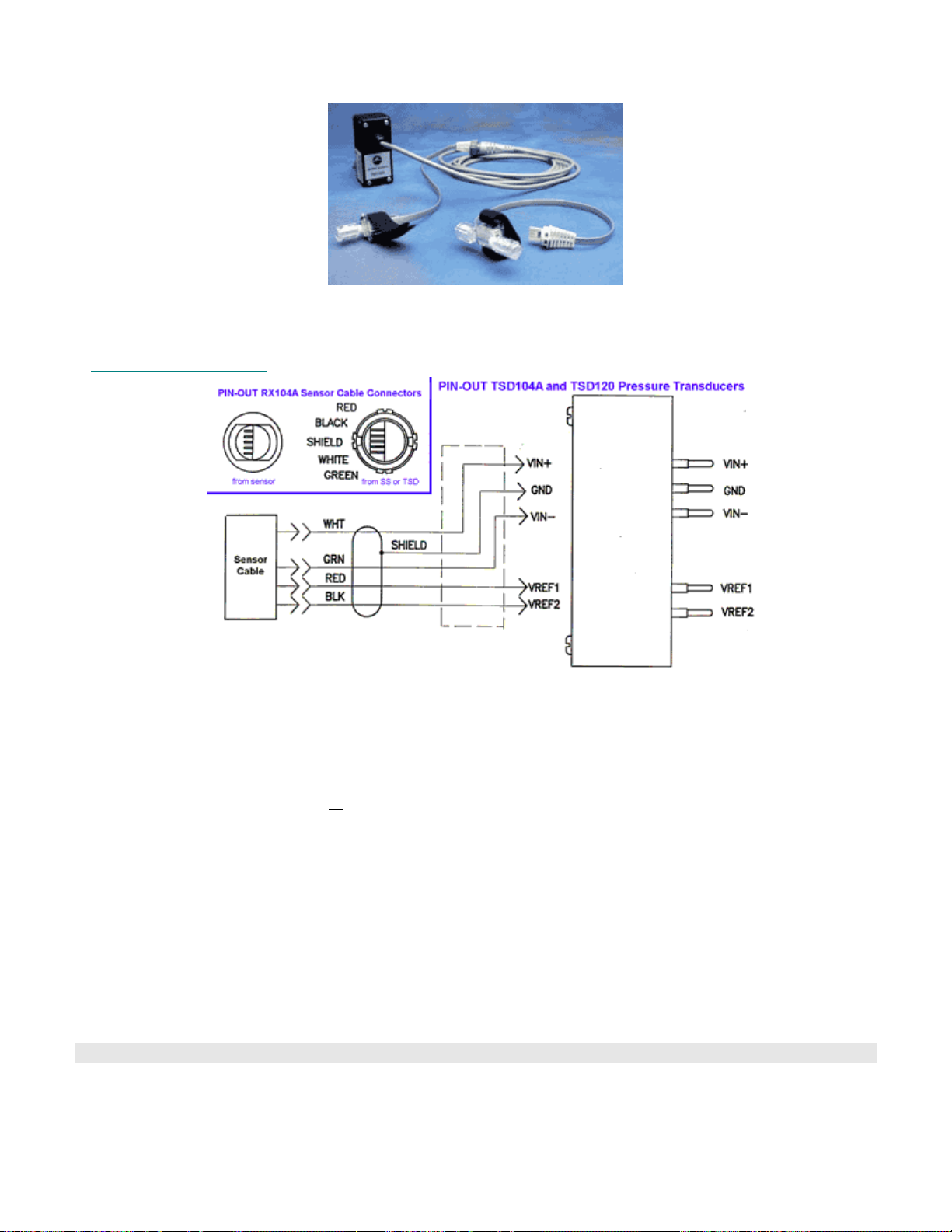
TSD104A BLOOD PRESSURE TRANSDUCER
RX104A Replacement Element
The TSD104A is used to measure direct arterial or venous blood pressure in animals for research or teaching. It is
designed to interface with the DA100C via a 3-meter cable (supplied). The RX104A is a replacement element for
the TSD104A blood pressure transducer; it does not include the TCI connector and cable.
TSD104A Specifications
Operational pressure: -50 mmHg to +300 mmHg
Overpressure: -400 mmHg to +4,000 mmHg
Dynamic Response: 100Hz
Unbalance: 50 mmHg max
Connection ports: Male Luer (2)
Eight-hour Drift: 1mmHg after 5 minute warm-up
Isolation: <
Defibrillation: Withstands 5 discharges of 400 joules in 5 minutes across a load
Operating temperature: +15° C to +40° C
Storage Temperature: -30° C to +60° C
Combined effects of sensitivity,
linearity, and hysteresis: 1 mmHg (nominal)
Output: 5 μV/mmHg (normalized to 1V excitation)
Weight: 11.5 grams
Transducer Dimensions: 67mm long x 25mm wide
Cable length: 3 meters
Interface: DA100C
TSD104A Calibration
See DA100C Calibration options on page
5 μA leakage at 120 VAC/60Hz
45.
48 MP System Hardware Guide
Page 49
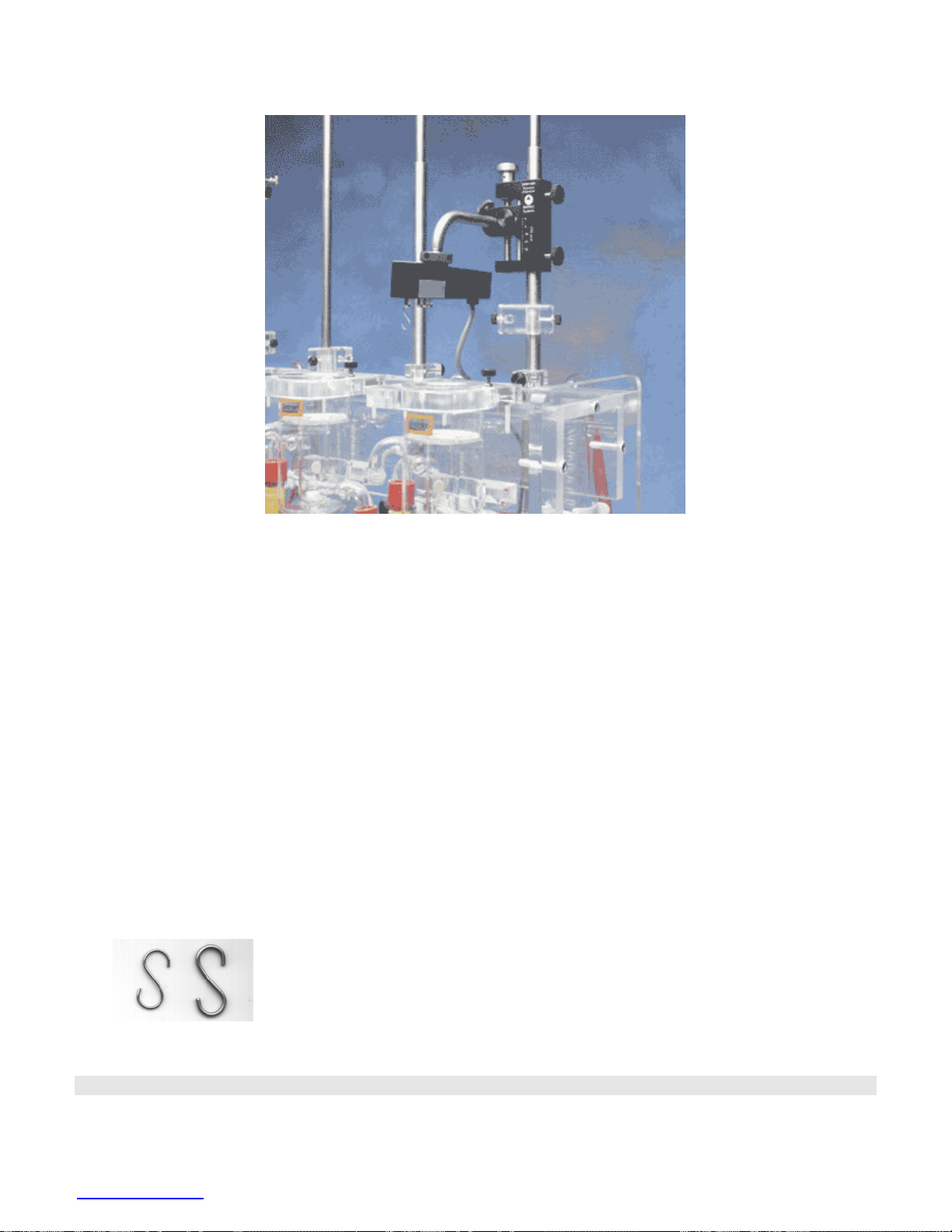
TSD105A ADJUSTABLE FORCE TRANSDUCER
TSD105A shown with HDW100A
Force transducers are devices capable of transforming a force into a proportional electrical signal. The
TSD105A force transducer element is a cantilever beam load cell incorporating a thin-film strain gauge.
Because the strain elements have been photolithographically etched directly on the strain beam, these
transducers are rugged while maintaining low non-linearity and hysteresis. Drift with time and temperature is
also minimized, because the strain elements track extremely well, due to the deposition method and the
elements’ close physical proximity. The TSD105A also incorporates impact and drop shock protection to insure
against rough laboratory handling.
Forces are transmitted back to the beam via a lever arm to insure accurate force measurements. Changing the
attachment point changes the full scale range of the force transducer from 50g to 1000g. The beam and lever
arm are mounted in a sealed aluminum enclosure that includes a 3/8” diameter mounting rod for holding the
transducer in a large variety of orientations. The TSD105A comes equipped with a 2-meter cable and plugs
directly into the DA100C amplifier.
The TSD105A mounting rod can be screwed into the transducer body in three different locations, two on the top
and one on the end surfaces of the transducer. The mounting rod can be placed in any angle relative to the
transducer orientation. The TSD105A can be used in any axis and can be easily mounted in any standard
measurement fixture, including pharmacological setups, muscle tissue baths and organ chambers.
The TSD105A has 5 different attachment points that determine the effective range of the force transducer.
These ranges are 50g, 100g, 200g, 500g and 1,000g. The point closest to the end is the 50g attachment point,
while the point closest to the middle is the 1,000g attachment point.
Two hooks are provided with the TSD105A. One with a .051” diameter wire
and the other with a .032” diameter wire. The larger hook is intended for the
500g and 1000g ranges and the smaller hook is to be used for the 50g, 100g and
200g ranges.
www.biopac.com 49
Page 50

TSD105A Calibration
The TSD105A is easily calibrated using weights of known mass. Ideally, calibration should be performed with
weights that encompass the range of the forces expected during measurement and should cover at least 20% of the
full scale range of the transducer. When calibrating for maximum range on the force transducer, use weights that
correspond to 10% and 90% of the full scale range for best overall performance.
See DA100C Calibration options on page
45.
TSD105A Specifications
Rated Output: 1mV/V (normalized to 1V excitation)
Ranges: 50, 100, 200, 500, 1000 grams
Noise (rms): (Range/50)mg @ 10 volts excitation, 1Hz bandwidth
Nonlinearity: <±0.025% FSR
Hysteresis: <±0.05% FSR
Nonrepeatability: <±0.05% FSR
30 minute creep: <±0.05% FSR
Temperature Range: -10°C to 70°C
Thermal Zero Shift: <±0.03% FSR/°C
Thermal Range Shift: <0.03% Reading/°C
Maximum Excitation: 10 VDC
Mounting Rod: 9.5mm (dia) – variable orientation
Weight: 300g (with mounting rod)
Length: 19mm (wide), 25mm (thick), 190mm (long)
Cable Length: 3 meters
Interface: DA100C—see page
43
50 MP System Hardware Guide
Page 51
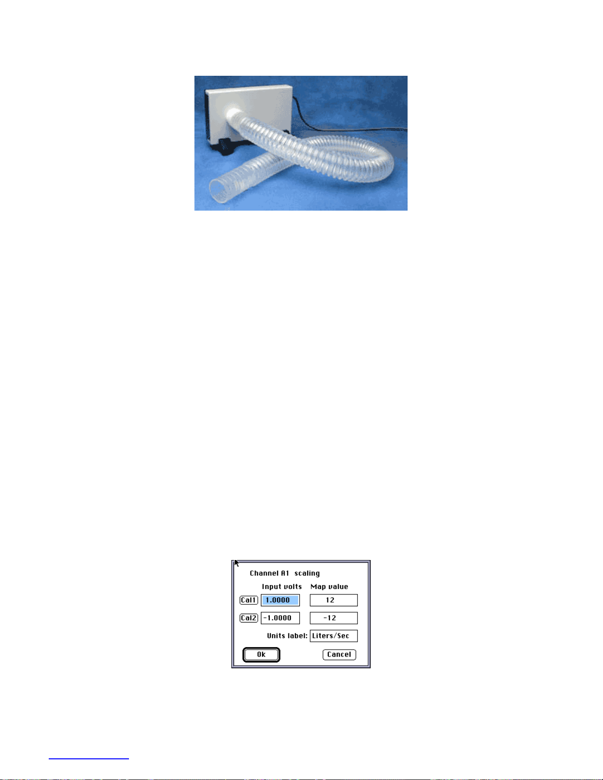
TSD107B HIGH-FLOW PNEUMOTACH TRANSDUCER
The TSD107B is a highly linear, wide range, airflow transducer. Using the TSD107B and a DA100C amplifier with
the MP System, you can perform a variety of tests relating to airflow and lung volume. With the equipment listed
below and the proper software parameters, precise lung volume measurements can be obtained.
Equipment
¾ MP System for data acquisition
¾ DA100C general purpose amplifier
¾ TSD107B pneumotach transducer
Hardware Setup
1. Select DA100C module for Channel 1.
2. Set Gain at 1000.
3. Set the high frequency response to 10Hz (300Hz in some cases).
4. Set the low frequency response to DC.
5. Set VREF1 to +1.0 Volts (default) with a Volt/ohm meter or with BIOPAC’s REFCAL (VREF2 will track
VREF1 with opposite polarity).
6. Plug the TCI connector into DA100C.
7. Insert the airflow tube between the bacterial filter and the airflow transducer.
8. Place the mouthpiece on the free end of the bacterial filter.
Software Setup
1. Under Setup Channels select channel 1 and click on the scaling button.
2. Complete the scaling dialog box as shown here:
3. Under Setup Acquisition set
a) Storage: Disk
b) Sample rate: 50 samples per second
c) Acquisition length: 30 seconds.
www.biopac.com 51
Page 52
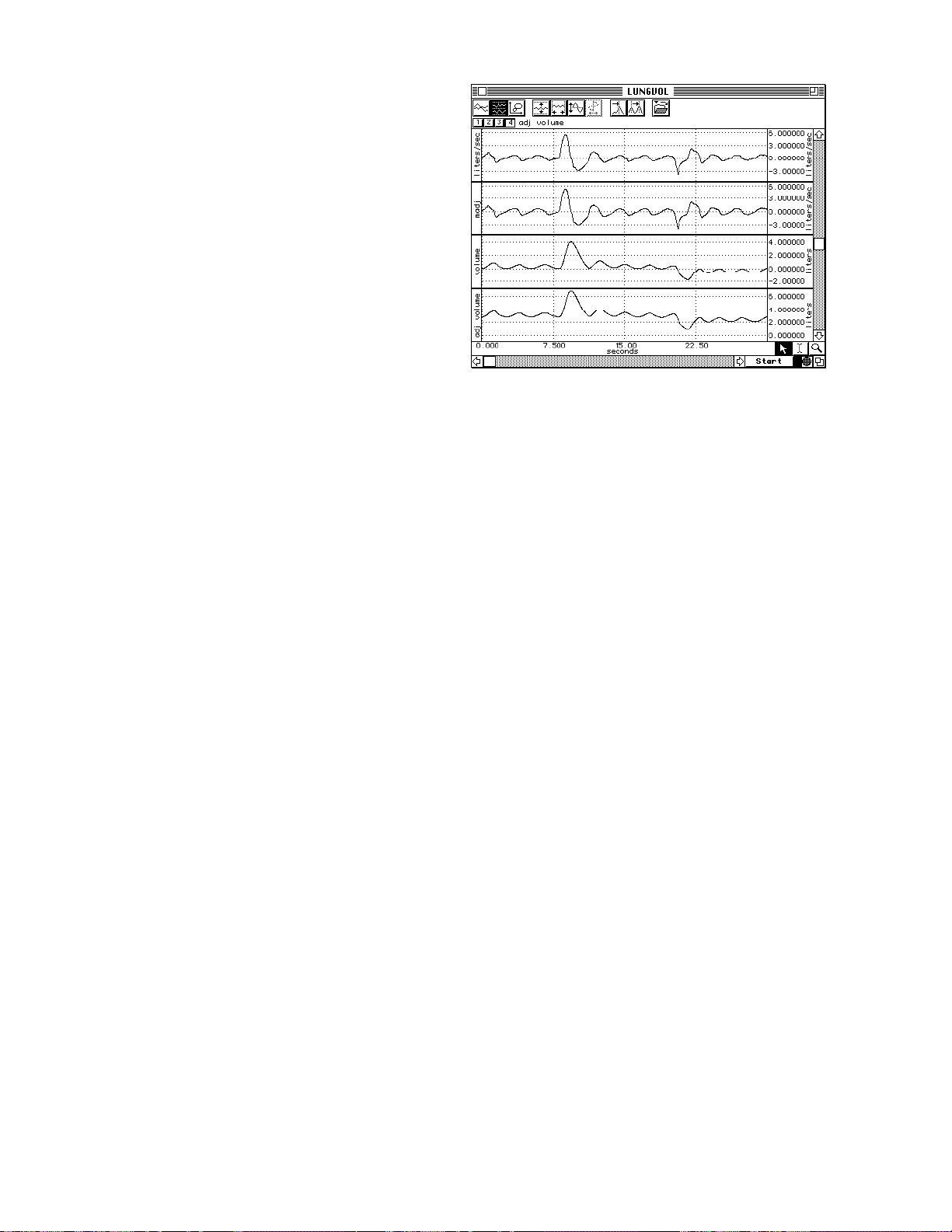
Recording Procedure
1. Start breathing normally through the mouthpiece.
2. After several normal breaths, inspire as deeply as you
can (just once) and then return to normal breathing for
several seconds
3. Expire as completely as you can.
4. Return to normal breathing for the remainder of
the recording.
The recorded wave should look something like the top
wave in the following graph. Normal Tidal Volume can
vary quite a bit, even over a 30-second period. Note that
in Wave 4 – adj volume, the starting tidal volume is
almost a liter, then, as the test progresses, the tidal
volume drops to about 0.5 liters. This level of variation is
somewhat expected, since respiratory effort has a
strong voluntary component.
Analysis — AcqKnowledge
1. Duplicate the recorded data.
2. Subtract the mean value of the entire record from the duplicated data to create the Mean Adjusted Flow
(madj). This procedure will simply remove any DC bias from the airflow signal.
3. Duplicate madj.
4. Integrate the duplicated madj channel. This process results in the third wave, which is the volume (in liters),
which correlates to the airflow.
5. To correct for the proper residual volume in the lungs (estimated at about 1 liter), add a constant to the third
wave to create a new adjusted volume (adj volume). The minimum point on this curve should be the
estimated residual lung volume (1 liter).
52 MP System Hardware Guide
Page 53
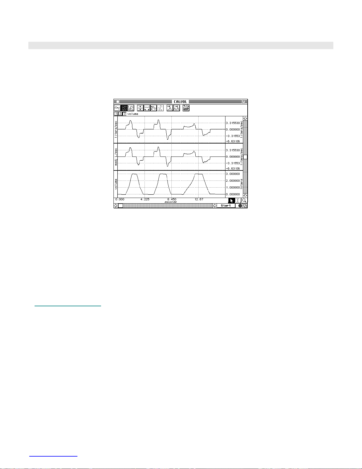
TSD107B Calibration
The TSD107B is factory calibrated to satisfy the scaling factor:
1 mVolt Δ output = 12.0 liters/sec flow rate
When connected to the DA100C with Gain =1,000, the calibration factor is:
1 Volt = 12.0 liters/sec
This graph illustrates how a calibration check is performed.
1. Insert a three-liter calibration syringe into the free end of the airflow tube.
2. Push three liters of air through the airflow transducer, first one direction, then the other.
3. Subtract the mean value of the first wave from the second wave, to correct for DC bias.
4. Integrate the second wave; the result will be placed in the third channel (volume).
As air is forced back and forth through the transducer, you would expect that the volume would be from 0 to 3
liters. As air goes one way the volume climbs to 3 liters, and as that same air is then pulled the other direction
through the transducer, the volume signal should head back to 0. As shown in the sample graph, the volume
measurement is independent of the rate of flow, as you would expect for a linear airflow measurement transducer.
See DA100C Calibration options on page
45.
TSD107B Specifications
Pneumotach type: Hans Rudolf® #4813 with integral differential pressure transducer
Voltage excitation: +/- 5 volts (10 volts pk-pk) maximum
Nominal Output: 45 µV/[liters/sec] (normalized to 1V excitation)
Calibration factor: 90 micro-volts/(liters/second) – normalized to 2 VDC excitation
Calibrated flow range: ±800 Liters/min
Dead space volume: 87.8 ml
Back pressure: 2.8 cm H
O/400 liters/min
2
Flow bore (Ports): 35mm OD
Weight: 690 grams
Dimensions: 4cm (deep) x 11cm (high) x 19cm (wide)
Cable: 3 meters
Interface: DA100C—see page
43
www.biopac.com 53
Page 54
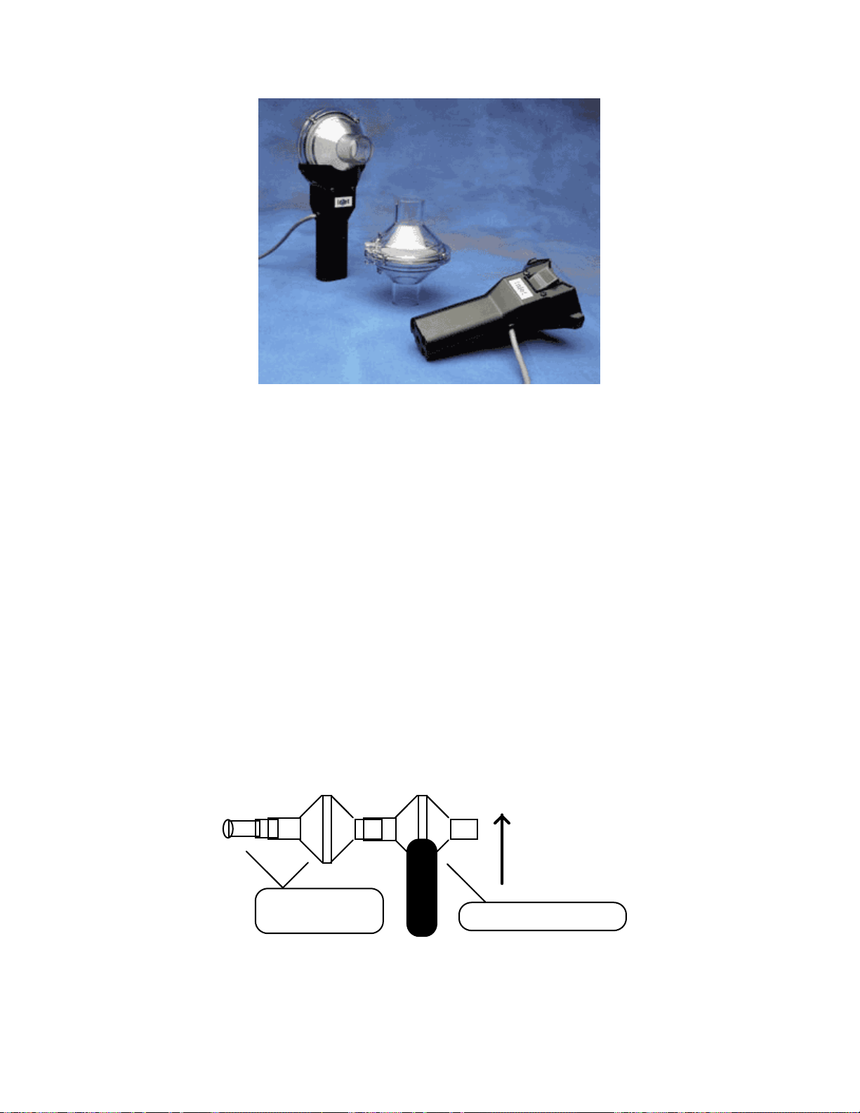
TSD117 MEDIUM-FLOW PNEUMOTACH TRANSDUCER
TSD117-MRI
MEDIUM-FLOW PNEUMOTACH TRANSDUCER FOR MRI
The TSD117 can be used to measure respiratory flow over a wide range of subjects and conditions. The TSD117
includes an optically clear detachable flow head (RX117) for easy cleaning and inspection. As the detachable flow
head is snapped into the TSD117 handle, the flow head plugs directly into an integral, precision low-differential
pressure transducer. Accordingly, the TSD117 will output an electrical signal proportional to respiratory flow. The
TSD117 plugs directly into the DA100C amplifier module. The RX117 detachable flow head can be cold sterilized,
autoclaved (220° F max), or placed in a dishwasher.
For airflow and lung volume measurements, use the TSD117 with the AFT2 mouthpiece and the AFT1
bacterial filter.
For measurements of expired gases, use the TSD117 with the AFT22 non-rebreathing T valve with AFT10
facemask and the AFT15A or AFT15B mixing chambers.
All connections can be performed with AFT12 (22mm ID) tubing and AFT11 series couplers (page
144).
Please note the following:
a) The bacterial filter and mouthpiece are disposable and are “one per person” items. Please use a new
disposable filter and mouthpiece each time a different person is to be breathing through the airflow
transducer.
b) For more effective calibration, use a bacterial filter between the calibration syringe and the airflow
transducer.
c) Either the bacterial filter and mouthpiece are inserted into the airflow transducer or the calibration syringe
(with attached filter) is inserted into the airflow transducer.
Normal measurement connections:
Vertical
Orientation
Mouthpiece and
Bacterial Filter
Air Flow Transducer
For the most accurate lung volume recording, be sure to use a noseclip to prevent airflow through the nose. Also, be
sure not to remove the airflow transducer assembly from your mouth during the recording. All air leaving or
entering your lungs must pass through the airflow transducer during the lung volume measurement.
Use the following measurement procedure for determining lung volume:
54 MP System Hardware Guide
Page 55
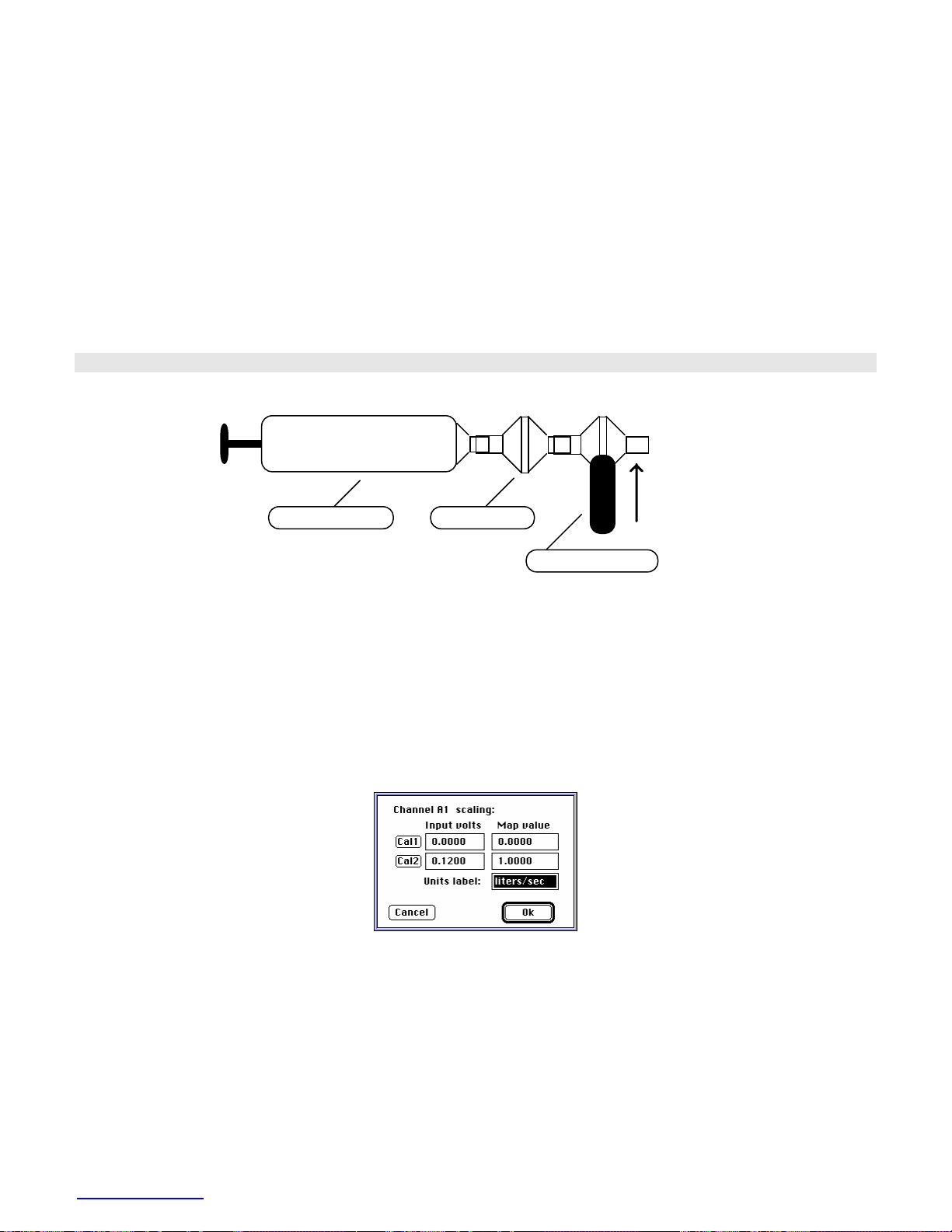
1. Breathe normally for 3 cycles (start on inspire)
2. Inspire as deeply as possible
3. Return to normal breathing for 3 cycles
4. Expire as deeply as possible
5. Return to normal breathing (end on expire)
Data Processing
When integrating the collected data to determine lung volume, it’s important to integrate from the starting point of
the first inspire, to the end point of the last expire. Before integration, you will need to determine the mean of the
selected (airflow) data and then subtract the mean from the record. This process insures that the integral will have
the same starting and ending point.
TSD117 Calibration
Calibration connections:
Vertical
Calibration Syringe
Bacterial Filter
Orientation
Air Flow Transducer
After the calibration process, please remove the calibration syringe and attach a new bacterial filter and mouthpiece
to the airflow transducer.
It’s very important that each individual use his/her own mouthpiece and bacterial filter.
Place the narrow end of the bacterial filter and mouthpiece assembly into either side of the airflow transducer. You
are now ready to begin recording airflow data. For best results, hold the airflow transducer vertically.
Calibration Procedure Options
The TSD117 can be roughly calibrated without using the calibration syringe. Using the TSD117’s nominal output of
60µV per liter/sec (normalized to 1 volt excitation), the following calibration factors can be entered in the
AcqKnowledge Scaling window.
Scaling Factors for Rough Calibration of the TSD117
The following equation illustrates why 0.12 volts maps to 1.00 liter/sec :
Calibration Constant • Amp Gain • Amp Excitation = Scale Factor
thus
60 µV/[liter/sec] • 1000 • 2 Volts = 0.12 V / [liter/sec]
Data can now be collected directly. Prior to analyzing the data, remember that there will always be some offset
recorded in the case of zero flow. It’s possible to largely trim this offset out, using the ZERO potentiometer on the
DA100 amplifier, but some residual will always remain.
www.biopac.com 55
Page 56
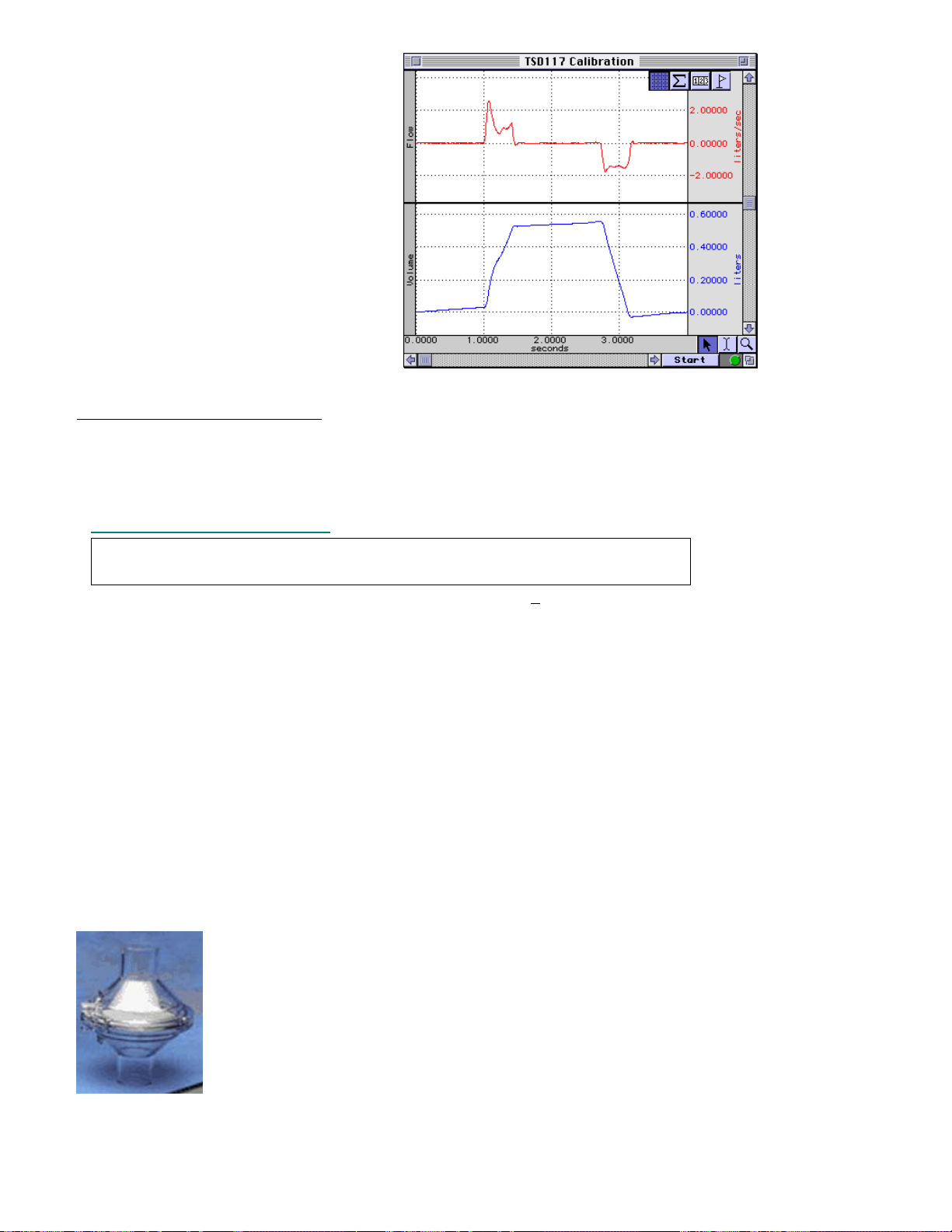
To remove residual offset after the flow data
has been collected, select a portion of the
baseline (zero flow reading) and calculate
the mean value using the popup
measurements. Subtract this mean value
from the raw data to obtain a mean
corrected flow signal.
Now, the integral of the mean can be
calculated as shown in this graph Æ
In this case, a 600ml-calibration syringe was
used to check the rough calibration of the
TSD117 airflow transducer. The rough
calibration indicates a syringe volume of
about 550ml, so this method may only be
expected to be accurate within ±10% of the
real reading.
Flow Measurement and Volume Calculation
To achieve a more exact calibration
indicated by the rough calibration. In this case, if the map value correlating to 0.12 volts were boosted about 10% to
1.10 (from 1.0 liters/sec), the resulting calibration would be fairly accurate.
Also see DA100C Calibration options on page
TSD117 Technical Specifications
Interface: DA100C—see page 43 MECMRI-DA to DA100C
Flow Rate: ±300 Liters/min highest linearity < 5 Liters/sec)
Nominal Output: 60 µV/[liters/sec] (norma1ized to 1 V excitation)
Dead space: 93 ml
1/4” 25 TPI mounting nut: standard camera mount
Flow Bore (Ports): 22 mm (ID), 29 mm (OD)
Flow Head Dimensions: 82.5 mm (dia) x 101.5 mm (long)
Flow Head Weight: 80 g
Flow Head Construction: Clear Polycarbonate
Handle Dimensions: 127 mm (long) x 23 mm (thick) x 35 mm (wide)
Handle Weight: 85 g
Handle Construction: Black ABS
Cable Length: 3 m, shielded
TEL100C Compatibility: SS11A—see page
, start with the above scaling factors and then boost or drop them slightly as
45.
TSD117 TSD117-MRI
227
RX117 REPLACEMENT AIRFLOW HEAD
The RX117 is a sterilizable airflow head for the TSD117 pneumotach transducer. The material
used in the flow head is polycarbonate and the screen is Stainless Steel. To reduce the cost of
disposable items, use the RX117 with the AFT8 sterilizable mouthpiece. (22mm ID/30mm
OD). Multiple RX117 heads help eliminate equipment downtime during cleaning procedures.
Recommended sterilization: cold sterilization (i.e., Cidex®) or autoclave. If autoclaved, RX117
Airflow Heads should be cleaned at the lowest autoclave temperature setting. The life cycle will
be about 10-20 cycles, depending upon temperature used.
56 MP System Hardware Guide
Page 57
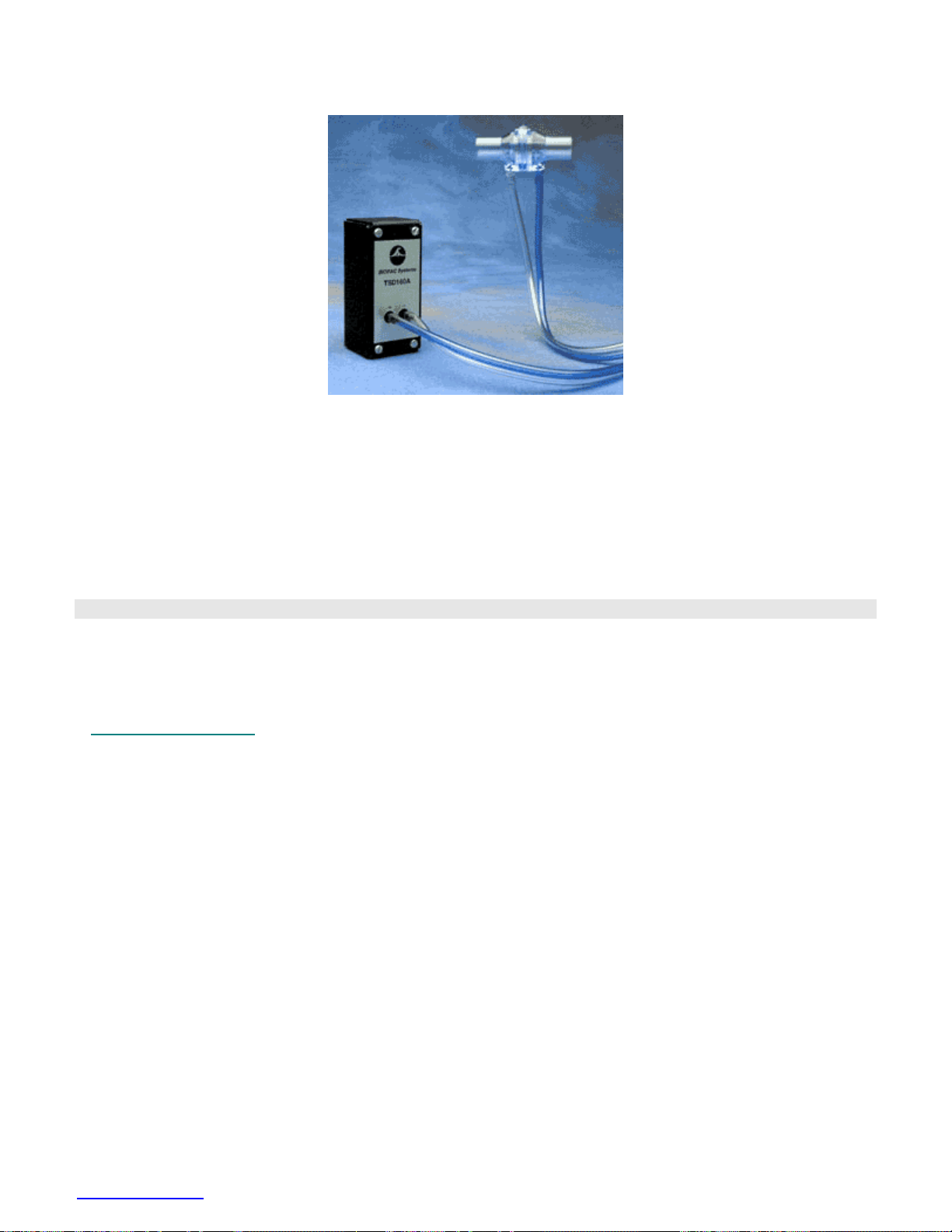
TSD127 PNEUMOTACH AIRFLOW TRANSDUCER (LOW FLOW)
The TSD127 can perform a variety of pulmonary measurements relating to airflow, lung volume and expired gas
analysis. The TSD127 is intended for animal use and consists of a low flow, pneumotach airflow head (RX127)
coupled to a precision, highly sensitive, differential pressure transducer (TSD160A). The TSD127 will connect
directly to a breathing circuit or plethysmogram chamber. The detachable flow head (RX127) makes cleaning and
sterilization easy.
For airflow and lung volume measurements, connect a short airflow cannula to the TSD127.
For measurements of expired gases, use the TSD127 with the AFT22 non-rebreathing valve.
All connections can be performed with AFT11 series couplers (page
TSD127 Calibration
Follow the procedure for TSD117 (see page
to the higher sensitivity to flow of the TSD127.
Also see DA100C Calibration options on page
TSD127 Specifications
Range: ± 90 Liters/min
Nominal Output: 500 µV/[liters/sec] (normalized to 1V excitation)
Dead Space: 11cc
Weight: 11 grams – airflow head
Dimensions: 5.7cm (long) – airflow head
Ports: 15mm OD / 11mm ID
Tubing Length: 1.8 meters (to DA100C)
Interface: DA100C
55) but move the calibration syringe plunger at a reduced velocity due
45.
144).
RX127 Replacement Airflow Head
The RX127 is a low airflow head for the TSD127 pneumotach transducer. Multiple RX127 heads help eliminate
equipment downtime during cleaning procedures. (11mm ID/15mm OD)
www.biopac.com 57
Page 58
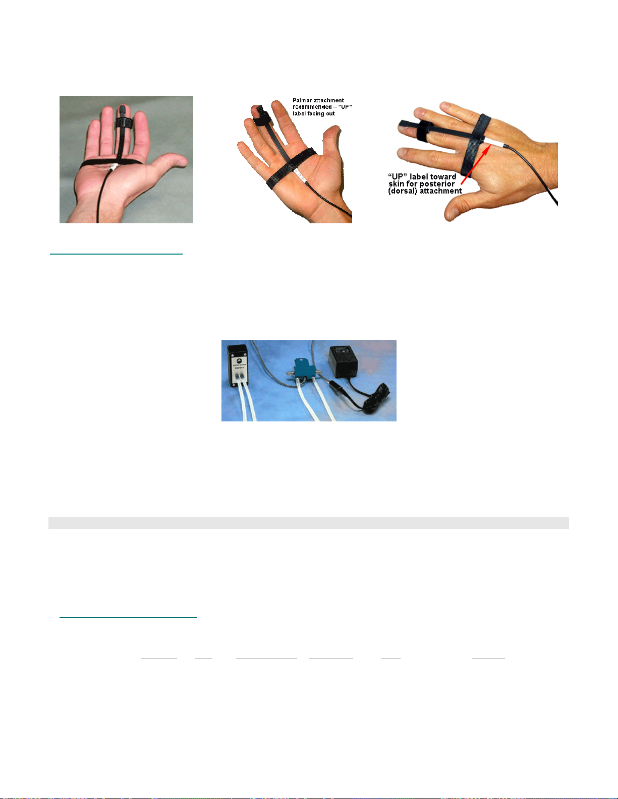
TSD131-MRI FINGER TWITCH TRANSDUCER FOR MRI
The TSD131-MRI transducers record finger twitch responses from human subjects in the MRI. The transducer
conforms to the shape of the finger and attaches via Velcro straps.
Palmar attachment recommended, with “UP” label facing out:
If a protocol requires posterior (dorsal) attachment, “UP” label must be placed toward skin for optimum response:
TSD131-MRI Specifications
Weight: 7 g
Dimensions (l x w): 14.6 cm x 0.50 cm Weight: 7 g
Cable Length: 8 m
Interface: MECMRI-HLT to HLT100C
TSD137 SERIES PNEUMOTACH AIRFLOW TRANSDUCERS (VERY LOW FLOW)
The TSD137 series pneumotachs can be used to perform a variety of small animal pulmonary measurements
relating to airflow, lung volume and expired gas analysis. The TSD137 series consists of a low flow, pneumotach
airflow head (RX137A through RX137E) coupled to a precision, highly sensitive, differential pressure transducer
(TSD160A). The TSD137 series pneumotachs will connect directly to a breathing circuit or plethysmogram
chamber. For airflow and lung volume measurements, connect a short airflow cannula to the TSD137 series flow
head. All of the TSD137 series pneumotachs come equipped with an internal heating element that can be optionally
attached to the AC137A 6 volt power supply (see page
TSD137 Calibration
Connect tubing and a flow restrictor between the calibration syringe and the TSD137 transducer, then follow the
procedure for TSD117 (see page
high sensitivity to flow of the TSD137 series. Each of the TSD137 series comes factory calibrated to a known flow
level, as indicated on the transducer.
Also see DA100C Calibration options on page
TSD137 Series Specifications
Dead Animal
Unit Range Space Output Flow Ports Approx. Approx.
(ml/sec)
TSD137A ±12 0.1 25.7 7 Small Mouse 30 g
TSD137B ±20 0.8 15.4 7 Mouse 50 g
TSD137C ±60 0.9 5.78 7 Rat/Guinea Pig 350 g
TSD137D ±150 2.0 2.10 10 Cat/Rabbit 750 g
TSD137E ±350 4.0 0.924 11 Small Dog 5.5 kg
Nominal Output: Normalized to 1 V excitation
Tubing Length: 1.8 m (to TSD160A)
Interface: DA100C
58 MP System Hardware Guide
55) but move the calibration syringe plunger at a reduced velocity due to the very
45.
(cc) (µV/[ml/sec]) (OD-mm) Size Weight
228).
Page 59
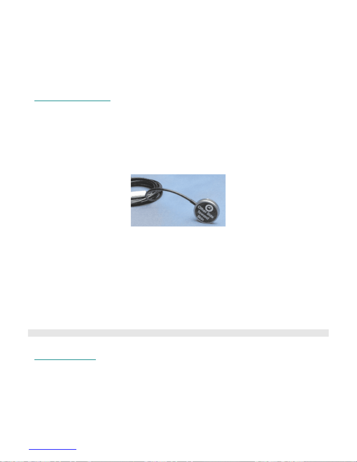
RX137 Series Replacement Airflow Heads
For TSD137 Series Pneumotachs
The RX137 series are low airflow heads for the TSD137 series pneumotach transducers. The RX137 heads can be
mixed and matched with any of the TSD137 series pneumotachs. Switching one head for another when using a
single TSD137 pneumotach can accommodate a wide range in flows. RX137 heads connect to the TSD160A
differential pressure transducer via standard 3mm or 4mm ID tubing. Multiple RX137 heads help eliminate
equipment downtime during cleaning procedures.
RX137 Series Specifications
Head Range Dead Space Length Flow Ports Weight
(ml/sec) (cc) (mm) ID (mm) OD (grams)
RX137A ±12 0.1 75 1.35 7 100
RX137B ±20 0.8 75 6.00 7 90
RX137C ±60 0.9 75 6.00 7 90
RX137D ±150 2.0 75 9.00 10 100
RX137E ±350 4.0 60 10.00 11 60
TSD108 PHYSIOLOGICAL SOUNDS TRANSDUCER
The TSD108 connects to the DA100C General Purpose Transducer Amplifier. The TSD108 can be used with the
TSD120 Noninvasive Blood Pressure Cuff or as a stand-alone device. If you use it with the TSD120, you can record
Korotkoff sounds for easy determination of systolic and diastolic blood pressure (see page for
used on its own, it can record a variety of acoustical signals, including heart sounds and sounds associated with
ribbing or grinding (e.g., Bruxism). The acoustical transducer element is a Piezo-electric ceramic disk that is bonded
to the interior of a circular metallic housing.
Grounding Note When using this transducer with the EBI100C module, do not connect the GROUND pin of
the TSD108 to the DA100C module. Doing so will cause inaccurate impedance measures,
because the TSD108 contact surface is tied to the isolated ground. An alternative is to
insulate the TSD108 from the skin surface by using a latex balloon or some other nonconductive barrier. If the latter procedure is followed, the GROUND pin may be attached to
the DA100 module.
TSD108 Calibration
The TSD108 does not require calibration.
60 details). When
TSD108 Specifications
Frequency Response: 35 Hz to 3500 Hz
Housing: Stainless Steel
Sterilizable: Yes (contact BIOPAC for details)
Noise: 5µV rms – (500 Hz - 3500 Hz)
Output: 2V (p-p) maximum
Weight: 9 g
Dimensions: 29 mm diameter, 6 mm thick
Cable Length: 3 m
Interface: DA100C
TEL100C Compatibility: SS17—see page
www.biopac.com 59
227
Page 60
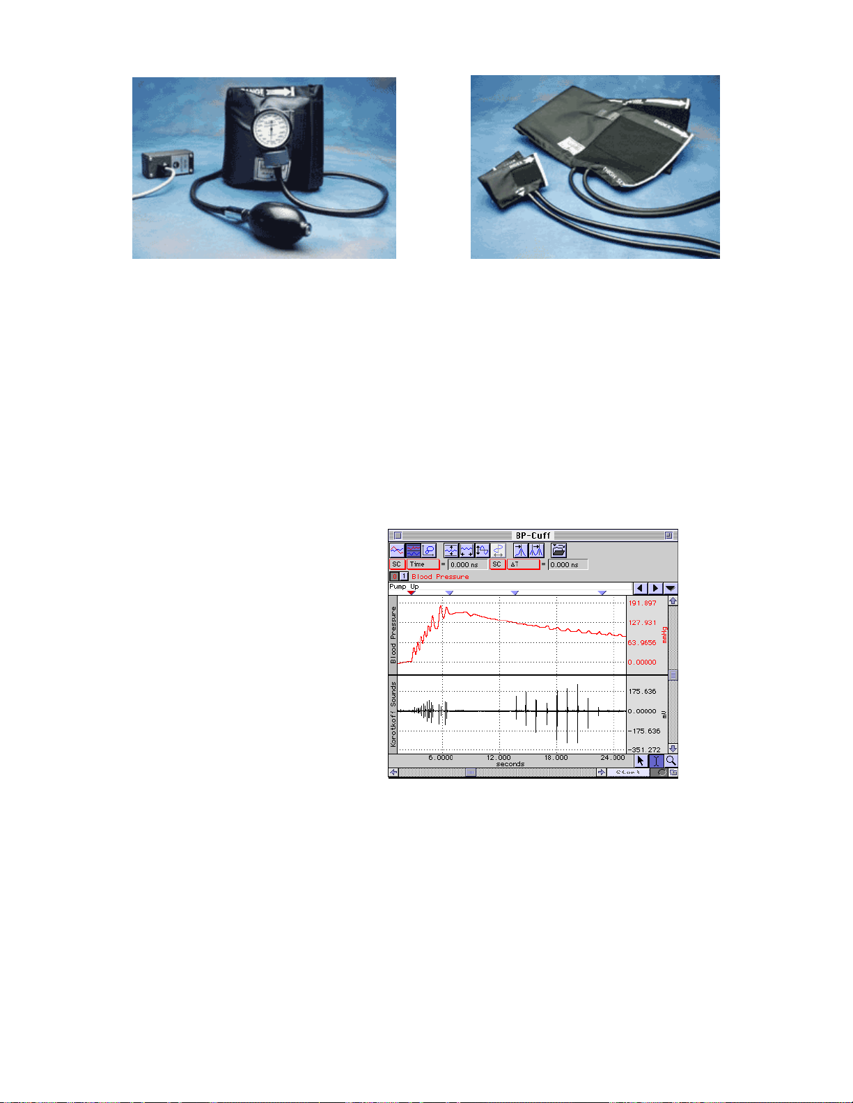
TSD120 BLOOD PRESSURE CUFF
TSD120 RX120A and RX120F cuff options
Blood Pressure Measurement
The most common form of indirect blood pressure measurement employs a pressure cuff, pump and pressure
transducer. This complete assembly is commonly referred to as a sphygmomanometer.
Typically, the cuff is wrapped around the upper arm and is inflated to a pressure exceeding that of the brachial
artery. This amount of pressure collapses the artery and stops the flow of blood to the arm. The pressure of the cuff
is slowly reduced as the pressure transducer monitors the pressure in the cuff. As the pressure drops, it will
eventually match the systolic (peak) arterial pressure. At this point, the blood is able to “squirt” through the brachial
artery. This squirting results in turbulence that creates the Korotkoff sounds. The Korotkoff sounds are detected
using a TSD108 physiological sounds transducer (see page
pressure eventually matches the diastolic pressure of the artery. At that point, the Korotkoff sounds stop completely,
because the blood is now flowing unrestricted through the artery.
The following graph illustrates a typical recording using the TSD120 and TSD108.
59). The cuff pressure continues to drop, and the
The TSD120 pressure signal was recorded via a
DA100C amplifier set to DC, 10Hz LP and a
gain of 200.
The TSD108 Korotkoff signal was recorded by
a DA100C amplifier set to .05Hz HP, 300Hz LP
and a gain of 50 to 200.
The signal for the TSD108 was further
conditioned by the AcqKnowledge software.
Cuff Blood Pressure Versus Korotkoff Sounds
In a calculation channel, the TSD108 signal is bandpass filtered from 50 to 200Hz. Accordingly, the sampling rate
for the entire recording needs to be about 600Hz, assuming the TSD108 transducer is used.
As the cuff is wrapped around the upper arm of the subject, be sure to place the TSD108 transducer underneath the
blood pressure cuff, directly over the brachial artery. TSD108 placement is very important to get the best possible
recordings of Korotkoff sounds. Finish wrapping the cuff around the upper arm and secure it with the Velcro
®
seal.
Now, start inflating the cuff with the pump bulb.
The pressure trace shows the hand pump driving the cuff pressure up to about 150 mmHg. Then the cuff pressure is
slowly released by adjusting the pump bulb deflation orifice. Notice that the Korotkoff sounds begin appearing
when the cuff pressure drops to about 125 mmHg (bottom trace). As the pressure continues to drop, the Korotkoff
sounds eventually disappear, at about 85 mmHg. The systolic pressure would be identified at 125 mmHg and the
diastolic pressure would be 85 mmHg.
60 MP System Hardware Guide
Page 61
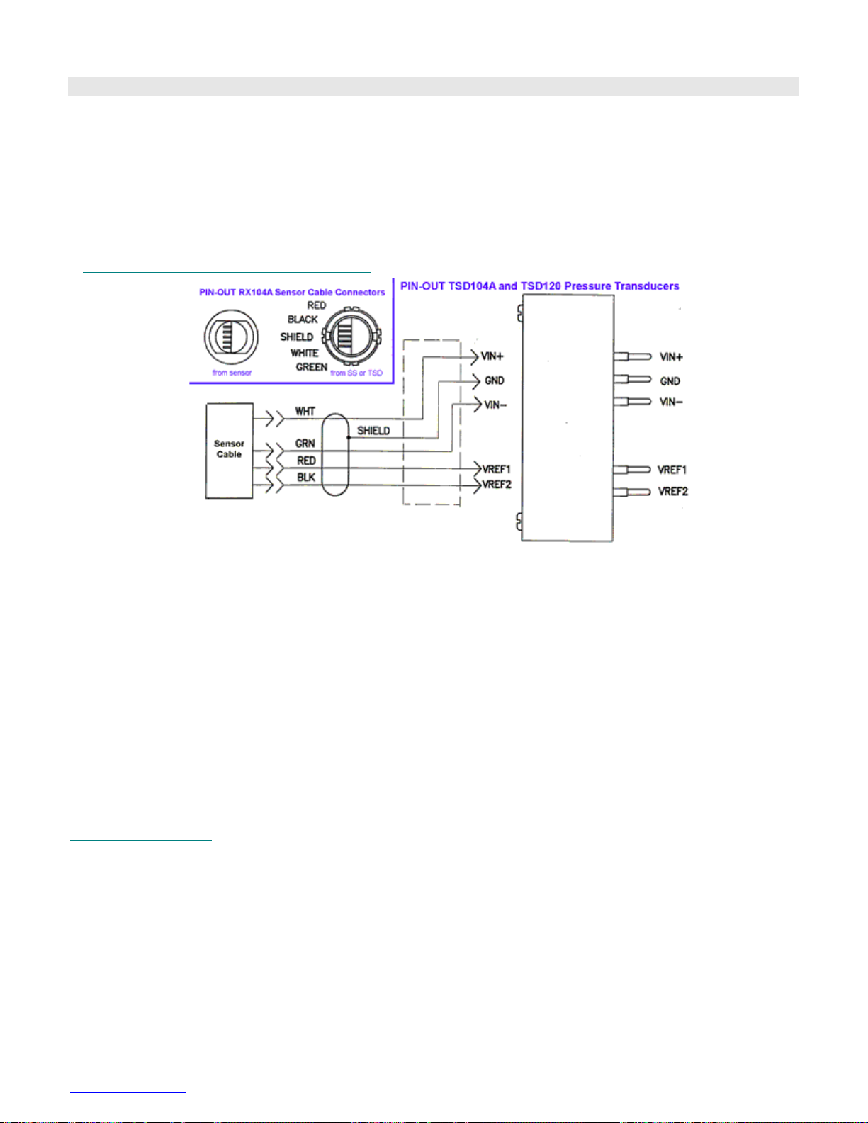
TSD120 Calibration
The TSD120’s built-in pressure transducer will require an initial calibration prior to use. To calibrate the transducer,
wrap the cuff into a roll and begin to inflate the cuff slowly with the pump bulb. You will notice the pressure change
on the mechanical indicator. Set the cuff pressure to one lower pressure (typically 20 mmHg) and then one higher
pressure (typically 100 mmHg). In this manner you can calibrate the pressure transducer using the standard
procedure in the SCALING dialog (in AcqKnowledge). To use the cuff at a future date, simply save the calibration
settings in a stored file.
Also see DA100C Calibration options on page
45.
TSD120 Blood Pressure Cuff Specifications
Pressure range: 20 mmHg to 300 mmHg
Manometer accuracy: ±3 mmHg
Output: 5 µV/mmHg (normalized to 1V excitation)
Cuff circumference range: 25.4 cm to 40.6 cm (as shipped with RX120D; cuff is switchable)
Cuff Dimensions: 14.5cm (wide) x 54cm (long)
Weight: 350 grams
Cable Length: 3 meters, shielded
Interface: DA100C
RX120 SERIES Blood Pressure Cuffsfor the TSD120
The RX120 series are optional blood pressure cuffs, of varying sizes, which can be quickly and easily swapped in
and out of the TSD120 noninvasive blood pressure cuff transducer. Use a single TSD120 and substitute one cuff for
another to accommodate a wide range in limb circumferences.
RX120 Specifications
Cuff Circumference Width Length
Range (cm) (cm) (cm)
RX120A 9.5-13.5 5.2 18.5
RX120B 13.0-19.0 7.5 26.1
RX120C 18.4-26.7 10.5 34.2
RX120D 25.4-40.6 14.5 54.0
RX120E 34.3-50.8 17.6 63.3
RX120F 40.6-66.0 21.0 82.5
www.biopac.com 61
Page 62

TSD121B-MRI HAND DYNAMOMETER FOR MRI
• Terminates in DSUB9 and requires
MECMRI-DA for proper operation.
1
The hand dynamometer measures clench force in the MRI. The lightweight, ergonomically designed transducer
provides direct readings in kilograms or pounds. Use in isolation or combine with EMG recordings for in-depth
studies of muscular activity. The isometric design improves experiment repeatability and accuracy. The isometric
design improves experiment repeatability and accuracy. The TSD121B-MRI has an 8 meter cable terminated for
connection to the MECMRI-DA. Simple calibration procedure makes this device very easy to use.
TSD121B-MRI Specifications
Isometric Range: 0-90 kg
Nominal Output*: 782 µV/kg
Weight: 323 g
Dimensions: 17.78 cm x 5.59 cm x 2.54 cm
Cable Length: 8 m
Interface: MECMRI-DA to DA100C in control room
* Nominal Output 782 uV/kg assumes that DA100C VREF1 is set to +1 volt, the factory default.
TSD121B-MRI Calibration
Sample calibration Sample values shown are for Gain 200 (per switch on the DA100C) and Range 20 kg
1. Multiply Gain by Nominal Output: 200 * 782 µV/kg = 0.1564 V/kg.
2. Multiply the result by the Range: 0.1564 V * 20 kg = 3.128 V per 20 kg range.
3. Plug the TSD121B-MRI into the cabling system/amplifier.
4. For CAL1: remove all weight from the TSD121B-MRI, press CAL1 to get the Input Value, and then enter
0 for Map (Scale) Value.
5. For CAL2: add 3.128 V (the result from step 2) to the CAL1 Input Value and enter it in the CAL2 Input
Value, and then enter 20 kg for the Map (Scale) Value.
6. Click OK.
62 MP System Hardware Guide
Page 63
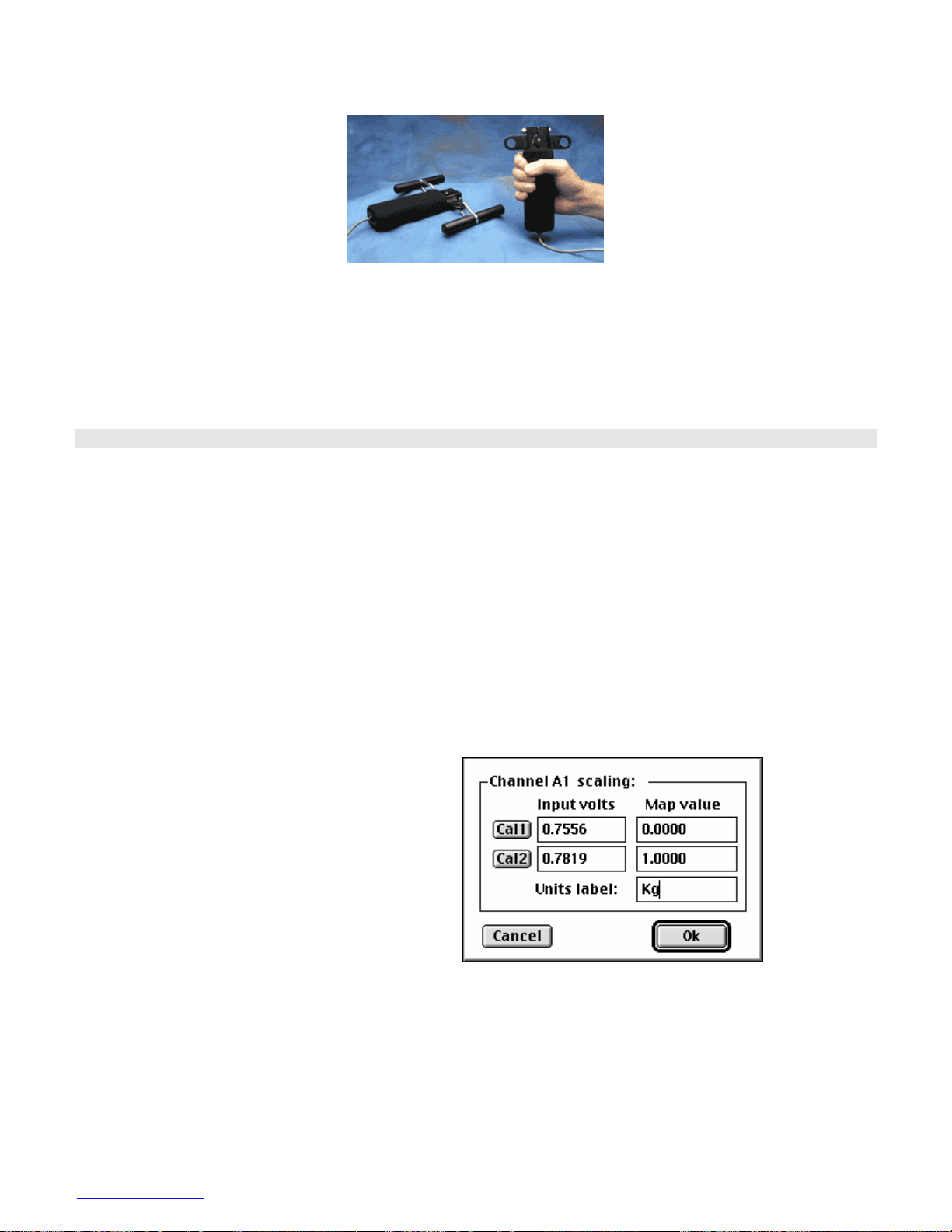
TSD121C HAND DYNAMOMETER
The multi-purpose hand dynamometer adds a new dimension to force measurements. This fully isometric transducer
can be used in the traditional hand grip strength fashion, pulled apart by both hands (the Dynagrips option), or
mounted against a wall and pulled. The hand dynamometer can be used in isolation, or combined with EMG
recordings for in-depth studies of muscular activity. The isometric design improves experiment repeatability and
accuracy. The hand dynamometer is designed to interface with the DA100C General Purpose Transducer Amplifier,
and the TEL100C remote monitoring module. The hand dynamometer transducer is the same for each system, but
they each use a different connector and a different part number. The equipment section provides you with a list of
the appropriate part numbers and interfaces.
TSD121C Calibration
With the proper equipment and correct scaling techniques described below, precise force measurements can be
obtained.
Equipment
TSD121C Hand Dynamometer
MP System and DA100C General Purpose Transduce Amplifier
SS25 Simple Sensor Hand Dynamometer
MP System and TEL100C Remote Monitoring Module Set
Hardware Setup
Connect the TSD121C to the DA100C, or the SS25 to the TEL100C. When using this type of transducer, proper
hand placement is at the uppermost portion of the foam grip, directly below the dynagrip connections.
Software Setup
1. Select Setup Channels under the MP menu
and enable one analog channel; make sure to
correlate this with the Analog Output
Channel you selected on the DA100C
module.
2. Select Scaling . A dialog similar to the one
shown here will be generated.
3. In the Map value column, enter the scaling
factors of 0 and 1, respectively. These
represent 0 and 1 kilograms.
4. Enter “Kg” for the Units label, as shown.
5. Take the TSD121C and rest it on the table.
6. Click on the Cal 1 button with the mouse to get a calibration reading.
To obtain a value for the Cal 2 box, add 13.15μV per volt of excitation to the value from the Cal 1 box. Currently,
the DA100C is factory set to 2 V (±1 V) of excitation. If you have set your amplifier to another level of excitation,
use the following equation wherein V = volts of excitation per 1 kg and G = gain setting on the DA100C or
TEL100C module:
(13.15μV*G * V) + Cal 1 = Cal 2
www.biopac.com 63
Page 64
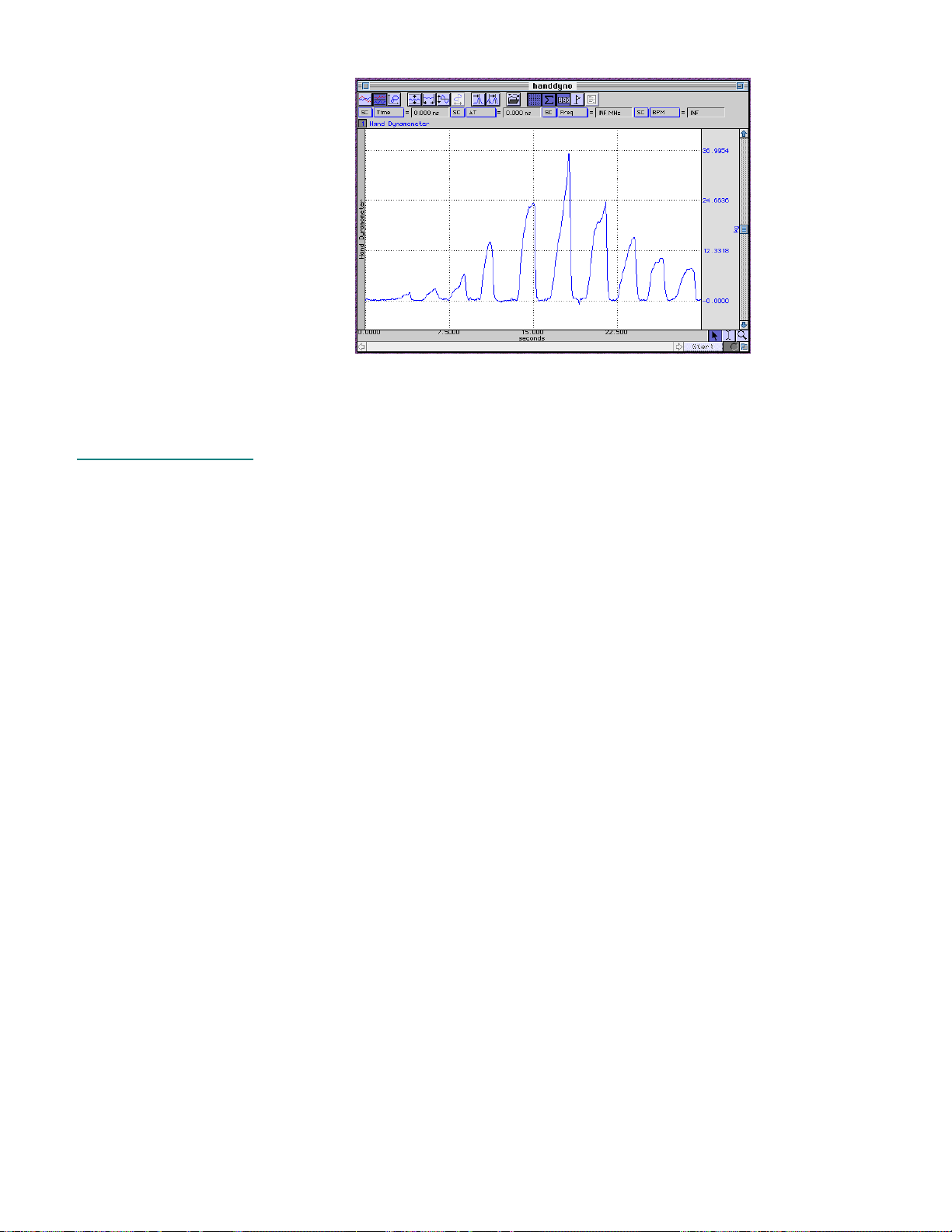
Testing Calibration
To see if the calibration is correct
for the MP System:
1. Start acquiring data.
2. Place the hand
dynamometer on a flat
surface.
3. Place a known weight on
the uppermost portion of
the grip.
4. Check the data — the
weight should be reflected
accurately in the data
acquired.
Sample Data
Also see DA100C Calibration options on page
45.
TSD121C Specifications
Isometric Range: 0-100 Kg
Nominal Output: 13.2 µV/kg (normalized to 1V excitation)
Weight: 315 g
Dimensions: 185 mm (long) x 42 mm (wide) x 30 mm (thick)
Cable Length: 3 m
Interface: DA100C—see page
TEL100C compatibility: SS25—see page
43
227
64 MP System Hardware Guide
Page 65
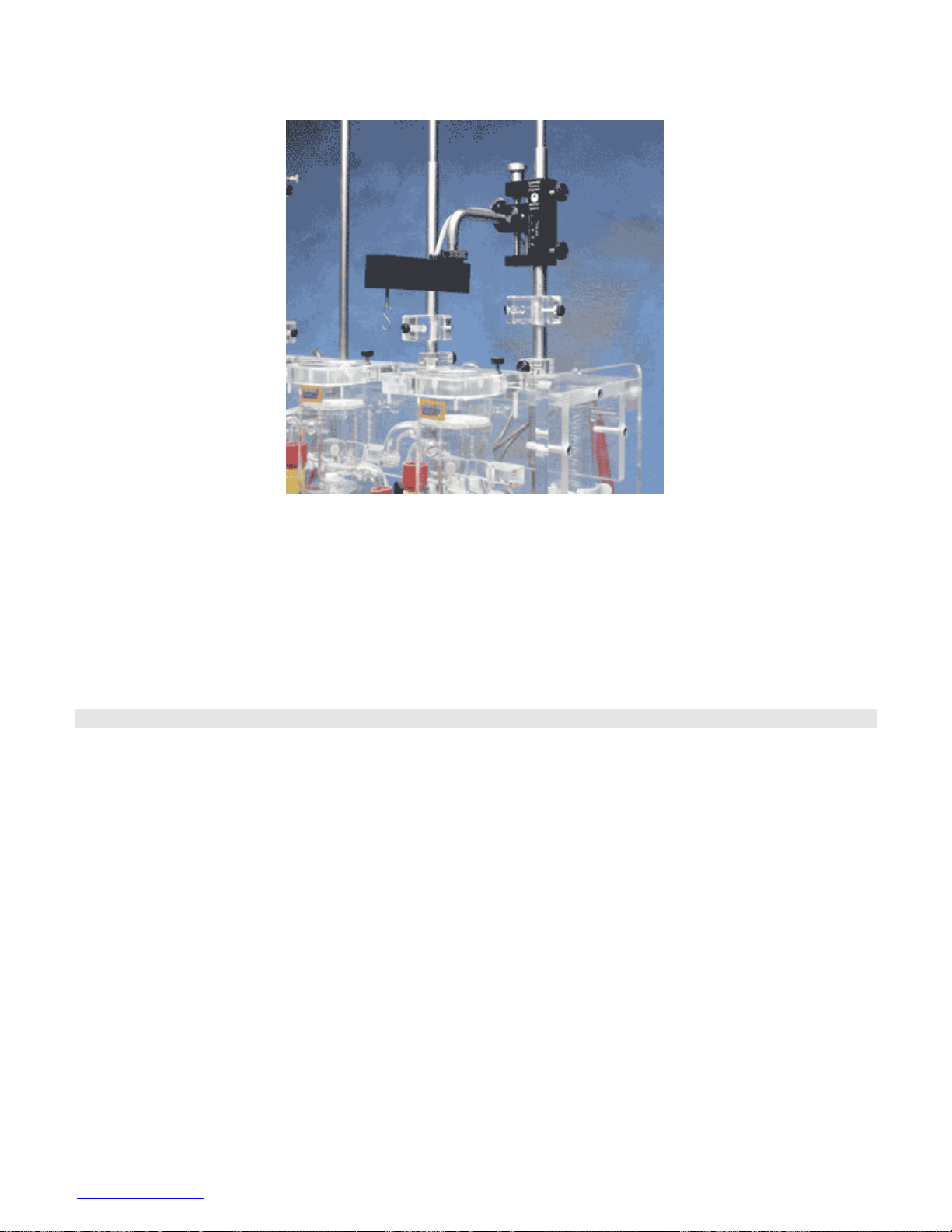
TSD125 SERIES PRECISION FORCE TRANSDUCERS
TSD125 shown with HDW100A
Force transducers are devices capable of transforming a force into a proportional electrical signal. The TSD125
series force transducer elements are cantilever beam load cells incorporating thin-film strain gauges. Because the
strain elements have been photolithographically etched directly on the strain beam, these transducers are rugged
while maintaining low non-linearity and hysteresis. Drift with time and temperature is also minimized, because the
strain elements track extremely well, due to the deposition method and the elements close physical proximity.
Forces are transmitted back to the beam via a self-centering pull-pin to insure accurate force measurements. The
cantilever beam is mounted in a sealed aluminum enclosure that includes a 3/8” diameter mounting rod for holding
the transducer in a large variety of orientations.
TSD125 Series Calibration
The following graphs illustrate actual data taken with the TSD125C (50 gram force transducer) and TSD125F (500
gram force transducer). The force transducers were connected directly to a DA100C amplifier with the excitation set
to ±5 Volts. The DA100C gain was set to 1,000. The RMS noise output was determined by calculating the standard
deviation of the amplified and calibrated signal over a period of time.
The RMS noise of each force transducer was determined in three different settings.
1) Channel 1 RMS Noise at DA100C output
2) Channel 41 RMS Noise after 10Hz Low Pass IIR real time filtering
3) Channel 40 RMS Noise after 1Hz Low Pass IIR real time filtering
www.biopac.com 65
Page 66
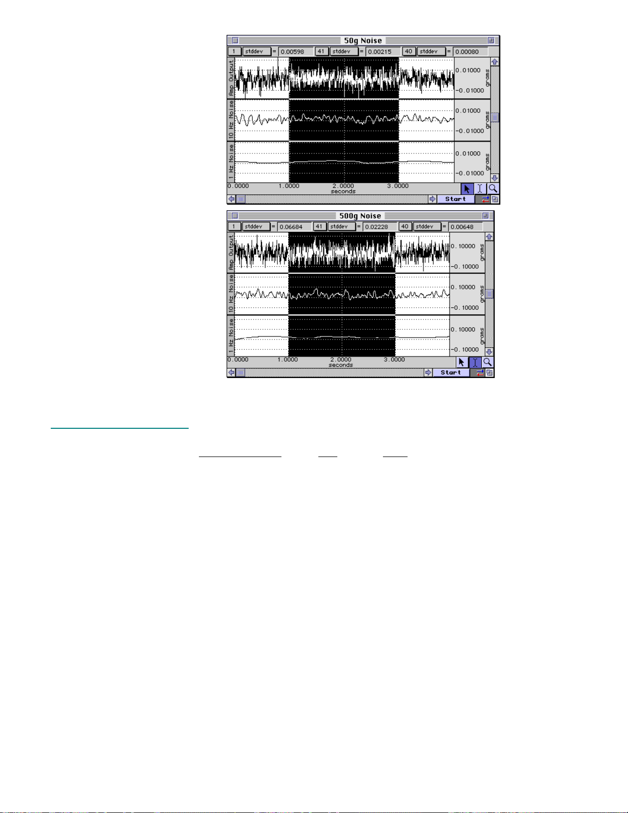
RMS noise performance of
TSD125F for different bandwidths
RMS noise performance of
TSD125C for different bandwidths
See DA100C Calibration options on page
45.
TSD125 series Specifications
Device Full Scale Range Noise [10 volts Excitation]
(FSR)
1Hz 10Hz
TSD125C: 50 gram 2.5 mg 1 mg
TSD125D: 100 gram 5 mg 2 mg
TSD125E: 200 gram 10 mg 4 mg
TSD125F: 500 gram 25 mg 10 mg
Nonlinearity: <±0.025% FSR
Hysteresis: <±0.05% FSR
Nonrepeatability: <±0.05% FSR
30-Minute Creep: <±0.05% FSR
Temperature Range: -10°C to 70°C
Thermal Zero Shift: <±0.03% FSR/°C
Thermal Range Shift: <0.03% Reading/°C
Maximum Excitation: 10 VDC
Full Scale Output: 1mV/V (normalized to 1V excitation)
Weight: 250 grams
Dimensions: 100mm (long) x 19mm (wide) x 25mm (high)
Mounting Rod: 9.5mm (dia) – variable orientation
Cable Length: 3 meters
Interface: DA100C—see page
43
66 MP System Hardware Guide
Page 67
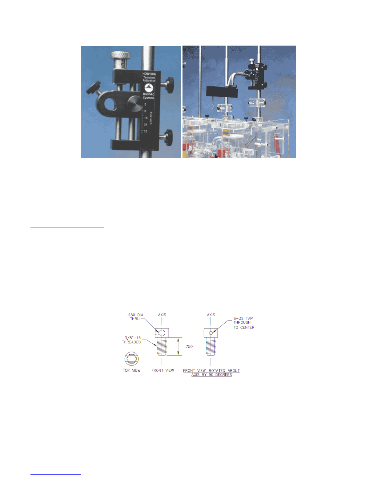
HDW100A FORCE TRANSDUCER TENSION ADJUSTER
HDW100A and TSD125
The HDW100A tension adjuster operates with the TSD105A and TSD125 series force transducers. The rugged
design and stability of the mounting allow for fine position control. The position adjuster is located on the top for
easy access and smooth operation. Vertical scales are provided for both metric and standard units. The HDW100A
slides directly onto vertical rod laboratory stands and force transducers are clamped into the unit horizontally.
HDW100A Specifications
Travel Range: 25mm
Resolution: 0.0025mm per degree rotation
Stand Clamp: 13.25mm ID
Transducer Clamp 11mm ID
Weight: 140 grams
Dimensions: 93mm (high) x 19mm (thick) x 74mm (deep)
HDW200 ADAPTER FOR 3RD-PARTY TENSION ADJUSTERS
This adapter allows 3rd-party tension adjusters to interface with BIOPAC Force Transducers.
• Fits any tension adjuster with an arm diameter of 6.35 mm (1/4") or less, such as “riser” style tension
adjusters from Lafayette and Wards.
www.biopac.com 67
Page 68
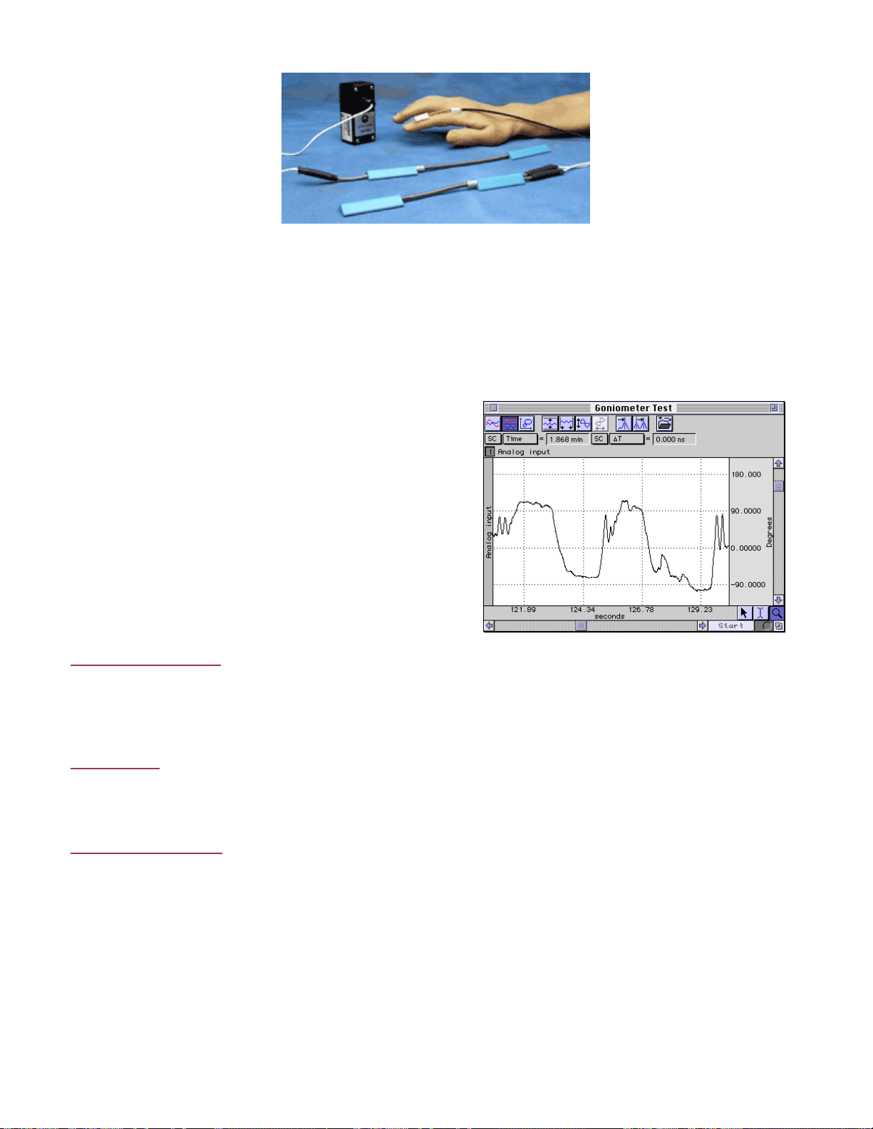
TSD 130 SERIES GONIOMETERS & TORSIOMETERS
The TSD130 Series are designed for the measurement of limb angular movement. Goniometers transform angular
position into a proportional electrical signal. The TSD130 series goniometers incorporate gauge elements that
measure bending strain along or around a particular axis.
The goniometers are unobtrusive and lightweight, and can be attached to the body surface using double-sided
surgical tape (and can be further secured with single sided tape). The goniometers have a telescopic endblock that
compensates for changes in distance between the two mounting points as the limb moves. The gauge mechanism
allows for accurate measurement of polycentric joints. All sensors connect directly to the MP150/100 unit as part of
an MP System. Activity data can be displayed and recorded, leaving the subject to move freely in the normal
environment.
The bending strain is proportional to the sum total angular shift
along the axis. Because the bending force is extremely small,
the output signal is uniquely a proportional function of the
angular shift.
In the example at right, the TSD130A was connected directly
to a DA100C amplifier, the DA100C gain was set to 1,000, and
AcqKnowledge was used to calibrate the signal to provide
angular measurements from approximately +90° to -90°.
Twin axis goniometers
Torsiometers
Single-axis goniometer
ATTACHMENT TO THE SUBJECT
Various combinations of display and recording instrumentation have been carefully developed fulfilling the
requirements of specific research applications. Due to the wide range of applications, one method of attachment
cannot be recommended. Experience has proven that standard medical adhesive tape is an excellent adhesion
method in the majority of cases. Single-sided and double-sided medical tape (such as BIOPAC TAPE1 or TAPE2)
should be used for the best results.
1) Attach pieces of double-sided tape to the underside of the goniometer endblocks.
Measure angular twisting (as on the torso, spine or neck) as opposed to bending.
Dual output devices that can measure angular rotation about two orthogonal planes
simultaneously. Goniometers provide outputs to simultaneously measure around two
orthogonally rotational axes (e.g. wrist flexion/extension and radial/ulnar deviations).
TSD130A — use on the wrist or ankle.
TSD130B — use on the elbow, knee or shoulder.
Torsiometers measure rotation about a single axis (e.g. forearm pronation/supination).
TSD130C — use on the neck.
TSD130D — use along the torso or spine.
Measures the angle in one plane only; designed to measure finger joint movement.
TSD130E — use on the fingers, thumb or toes.
68 MP System Hardware Guide
Page 69
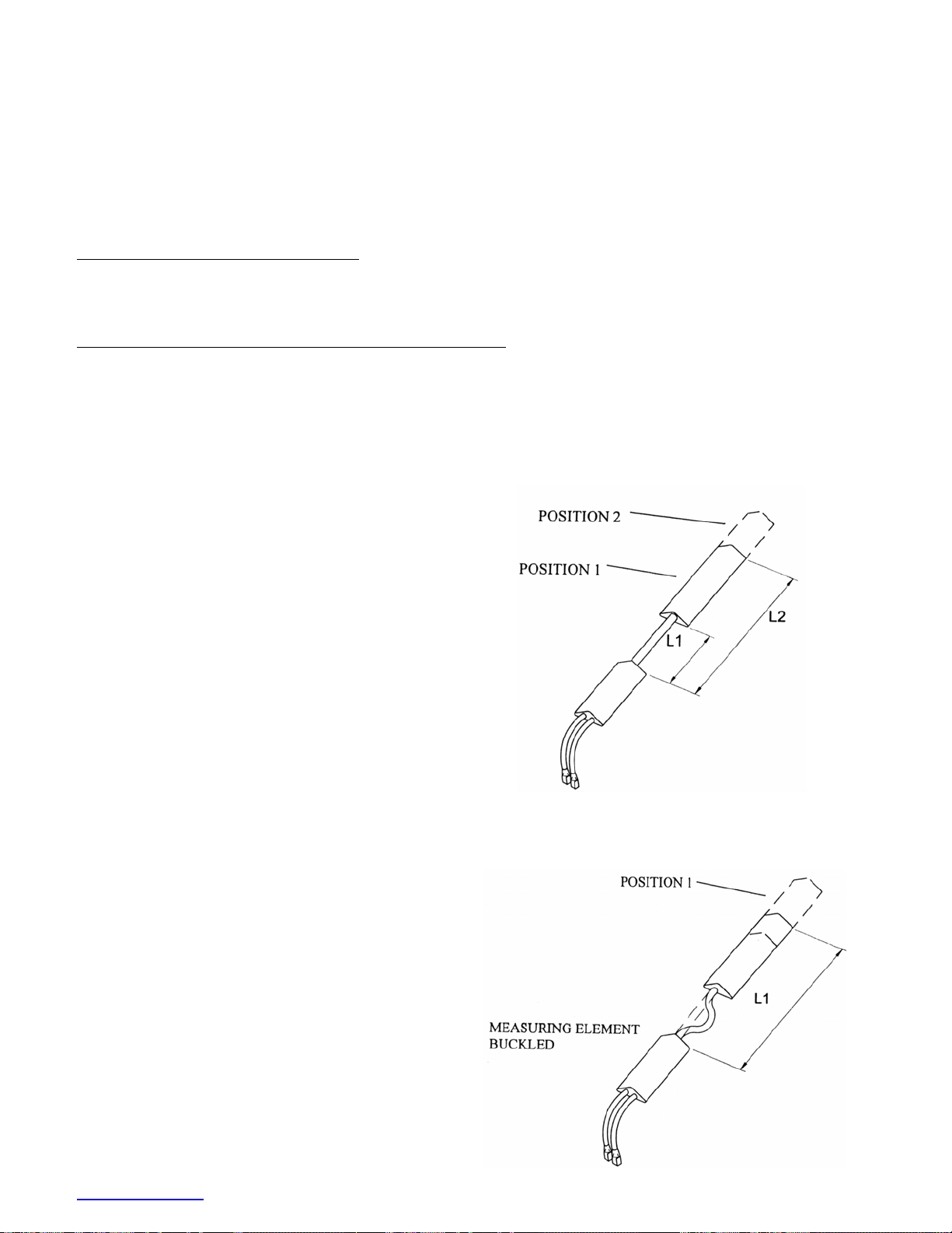
2) Stick the tape to the subject and allow for the telescoping of the goniometer. The goniometer should be fully
extended when the joint is fully flexed.
3) Press the two endblocks firmly onto the subject and ensure that the goniometer is lying over the top of the joint.
When the joint is extended, the goniometer may present an “oxbow.”
4) For additional security, pass a single wrap of single-sided medical tape around each endblock.
5) Secure the cable and connector leaving the goniometer with tape to ensure that they do not pull and detach the
goniometer.
For accurate results from long recordings
Employ double-sided adhesive between the endblocks and skin, and place single-sided adhesive tape over the top of
the endblocks. No tape should come into contact with the spring. You should also tape the connection lead down
near the goniometer.
For applications where quick or rapid movements are involved
Fit a “sock” bandage over the whole sensor and interconnect lead. This does not apply to goniometer TSD130E,
which has a different working mechanism.
When the goniometer is mounted across the joint, the center of rotation of the sensor measuring element may not
coincide with the center of rotation of the joint (for example, when measuring flexion /extension of the wrist). As
the joint moves through a determined angle, the relative linear distance between the two mounting positions will
change.
To compensate for this, all sensors are fitted with a
telescopic endblock that permits changes in linear
displacement between the two endblocks along axis ZZ
without the measuring element becoming over-stretched
or buckled.
In the free or unstretched position, the distance between
the two endblocks is L1.
If a light force is applied, pushing the endblocks away
from each other, this length will increase to a maximum
of L2.
When the light force is removed, the distance between
the two endblocks will automatically return to L1.
This creates several advantages: accuracy is improved; sensors can be worn comfortably and undetected under
normal clothing; the tendency for the position of the sensors to move relative to the underlying skeletal structure is
reduced.
If a light force is now applied, pushing the two
endblocks linearly towards each other, the only way the
distance L1 can decrease in length is if the measuring
element buckles.
Buckling is detrimental to the accuracy of the
TSD130A, TSD130B, TSD130C and TSD130D sensors,
so attachment instructions are provided (on page
75) for
the most commonly measured joints, to ensure that it
does not occur in practice.
There is no universal rule governing which size of
sensor is most suitable for a particular joint; this depends
on the size of the subject.
www.biopac.com 69
Page 70

In general, the sensor must be capable of reaching across the joint so that the two endblocks can be mounted where
the least movement occurs between the skin and the underlying skeletal structure. In certain circumstances, more
than one size of sensor will be appropriate.
WARNINGS
1. Take care to handle the goniometer and torsiometer sensors as instructed. Mishandling may result in
inaccurate data, reduced equipment life, or even failure.
2. Observe the minimum bend radius value for each goniometer and torsiometer at all times, particularly when
attaching and removing the sensors from the subject. Failure to do this will result in reduced equipment life
or failure.
3. Never remove the goniometer from the subject by pulling on the measurement element and/or protective
spring. Remove the endblocks individually and carefully, making sure not to exceed the minimum
permissible bend radius, particularly where the measuring element enters the endblocks.
4. Take care when mounting goniometers to ensure that the measurement element always forms a “simple”
bend shape. Accuracy will be reduced if an “oxbow” shape occurs in the element.
5. Do not bend the finger goniometer more than ±20° in the Y-Y Plane or reduced equipment life and/or
failure may result.
6. Do not exceed rotations of ± 90° about ZZ. Exceeding the torsiometer range may result in a reduction of the
life of the unit or failure.
7. Disconnect the transducers from the MP150/100 before cleaning or disinfecting goniometers and
torsiometers.
70 MP System Hardware Guide
Page 71

MAINTENANCE & SERVICE
No periodic maintenance is required to ensure the correct functioning of the sensors.
The sensors contain no user serviceable components.
If the sensor fails, it should be returned to BIOPAC Systems, Inc.
Please request a Return Merchandise Authorization (RMA) number before
you return the sensor and include a
description of what has been observed and what instrumentation was in use at the time of sensor failure in the return
package.
TSD130 Series Calibration
Each goniometer requires a DA100C amplifier per rotational axis. Accordingly, the twin axis goniometers will need
two DA100C amplifiers to measure both rotational axes simultaneously. The recommended DA100C excitation
voltage is ±5 VDC.
When using all goniometers and torsiometers, the minimum value of bend radius must be observed at all times,
particularly when attaching and removing the sensors from the subject. Failure to do this will result in reduced unit
life or failure.
The sensors have been designed to be as light as possible and the operating force to be a minimum. This permits
free movement of the joint without influence by the sensors. The sensors measure the angle subtended between the
endblocks. Use the software calibration features (Under Setup Channels) to calibrate any of the BIOPAC series
goniometers.
See DA100C Calibration options on page
45.
TSD130 Specifications
Part: TSD130A TSD130B TSD130C TSD130D TSD130E
Type: Goniometer Goniometer Torsiometer Torsiometer Goniometer
Channels: 2 2 1 1 1
Range: ±180° ±180° ±90° ±90° ±180°
Max Length: 110mm 180mm 110mm 180mm 35mm
Min Length: 75mm 130mm 75mm 130mm 30mm
Cable(s): 2 2 1 1 1
Weight: 17g 19g 17g 19g 8g
Cable Length: 3 meters
Nominal Output: 5 µV/degree (normalized to 1V excitation)
Interface: DA100C—see page
TEL100C Compatibility: SS20 thru SS24—see page
43
227
www.biopac.com 71
Page 72
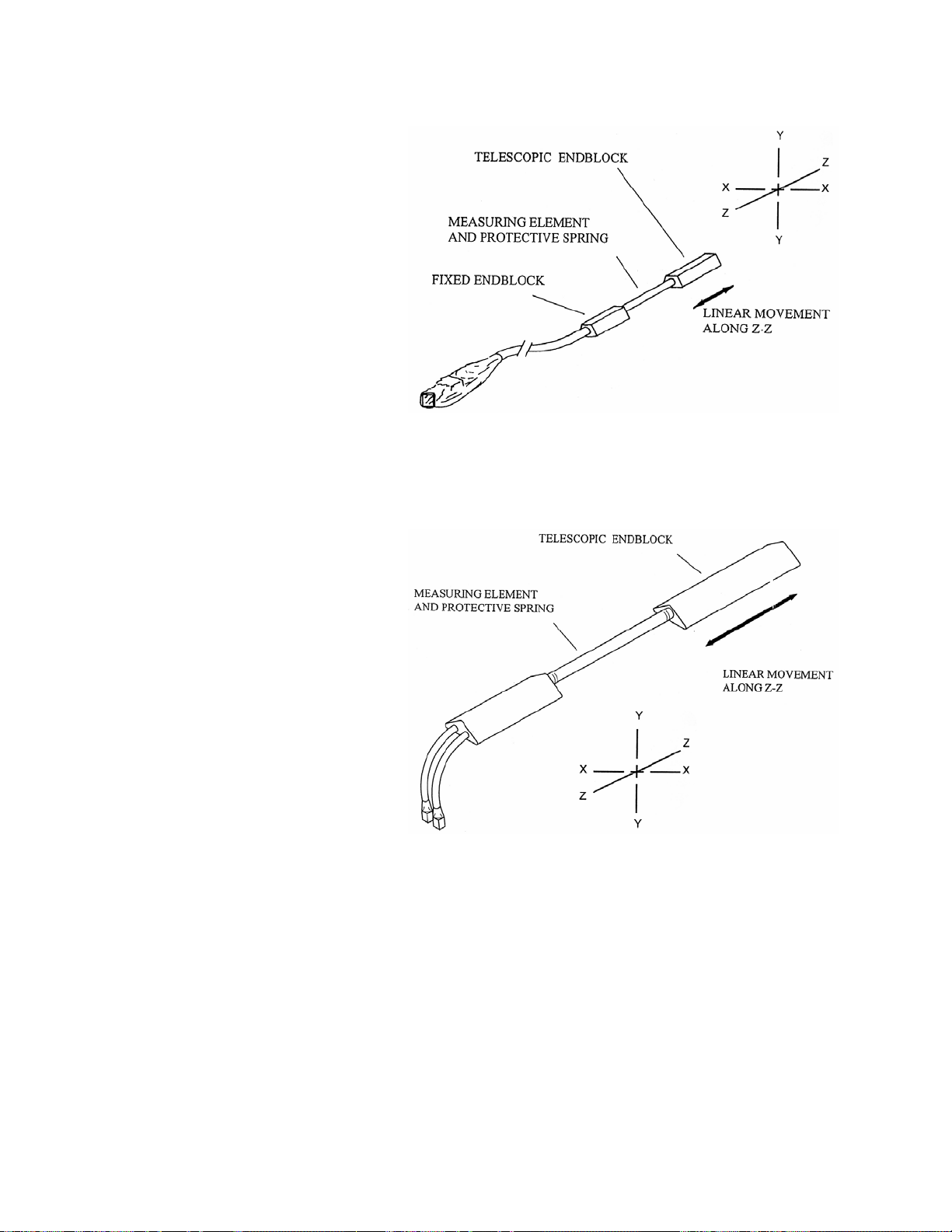
OVERVIEW OF THE BIOPAC GONIOMETER SERIES
As with all measuring equipment, to correctly interpret the data, you should understand the working principles (i.e.,
what the sensor measures) before use. BIOPAC Systems, Inc. manufactures three types of sensors:
1.
The TSD130E single axis finger
goniometer permits the measurement of
angles in one plane.
Angles are measured when rotating one
endblock relative to the other about axis
X-X.
The goniometer is not designed to
measure rotations about Y-Y. Any
attempt to bend the unit in this way
more than ± 20 from the neutral position
will result in a reduction of the life of
the unit or failure.
The goniometer does not measure rotations about axis Z-Z,
though this movement is permitted without reduced life or
damage occurring. This goniometer is designed primarily for
the measurement of finger and toe flexion/extension.
2.
The TSD130A and TSD130B twin axis
goniometers permit the simultaneous
measurement of angles in two planes,
e.g. wrist flexion / extension and radial /
ulnar deviation. Rotation of one
endblock relative to the other about axis
X-X is measured using the gray plug.
Similarly, rotation of one endblock
relative to the other about axis Y-Y is
measured using the blue marked plug.
Assuming the goniometer is mounted correctly (as outlined here), the outputs of the two channels are
independent of linear displacements along axis Z-Z.
It should be noted that rotation of one endblock relative to the other around axis Z-Z cannot be measured.
All TSD130A and TSD130B series goniometers function in the same way, and differ only in size.
72 MP System Hardware Guide
Page 73
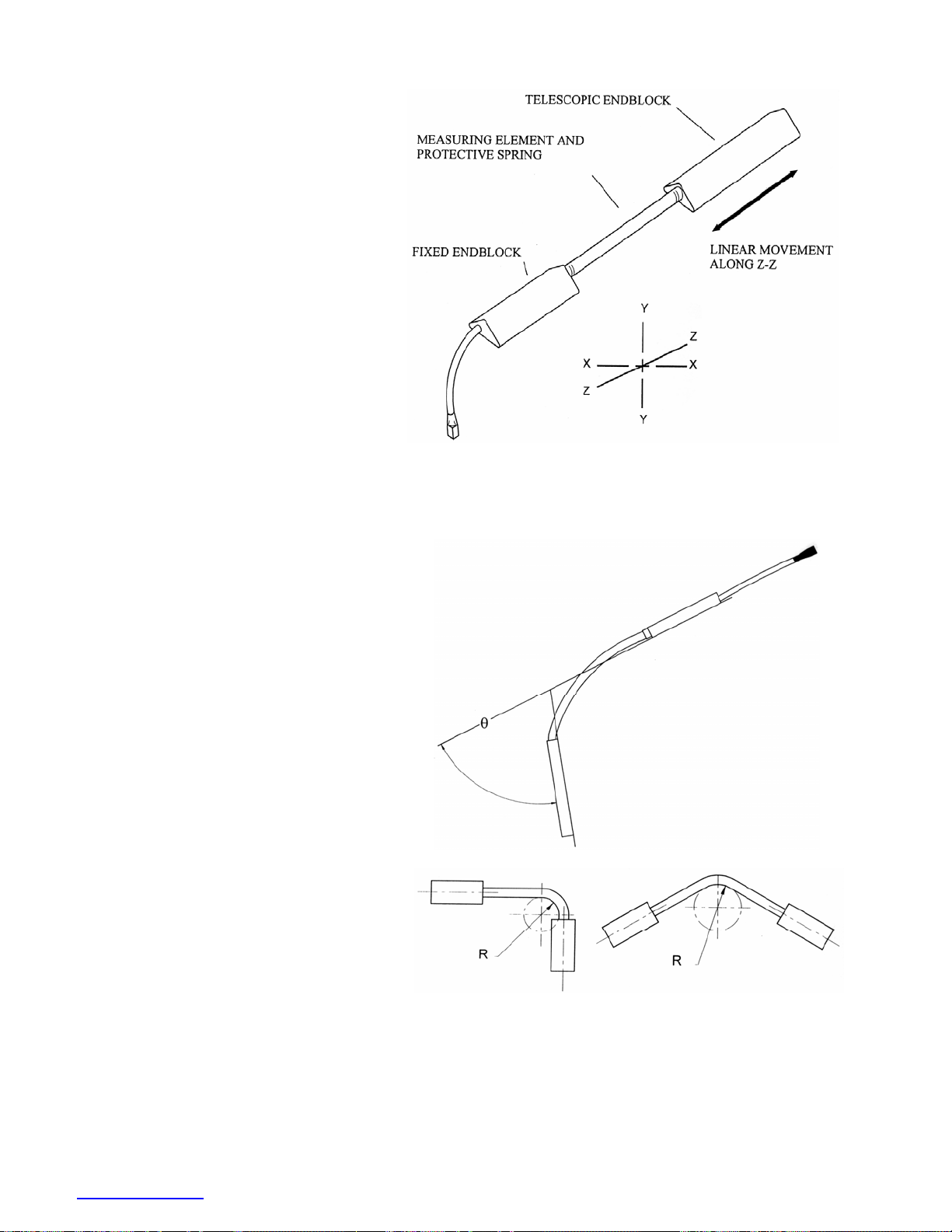
3.
The TSD130C and TSD130D single
axis torsiometers permit the
measurement of rotation in one plane,
e.g. forearm pronation/supination.
Axial rotation of one endblock relative
to the other along axis Z-Z is measured
from the gray plug.
If the torsiometer is bent in planes X-X
or Y-Y, the output remains constant.
All torsiometers function in the same
way, and difference only in size.
WARNING!
Torsiometers measure rotations about ZZ in the
range ± 90°. Exceeding the range may result
in a reduction of the life of the unit or failure.
The working mechanism is the same for
all three types of sensors. There is a
composite wire between the two
endblocks that has a series of strain
inside the protective spring gauges
mounted around the circumference. As
the angle between the two ends changes,
the change in strain along the length of
the wire is measured and this is equated
to an angle. The design is such that only
angular displacements are measured.
If the two ends move linearly relative to
each other, within the limits of telescopic
endblock, without changing the relative
angles between them, then the outputs
remain constant.
The amount of strain induced in the
gauges is inversely proportional to the
bend radius that the beam is bent around.
If the stated minimum permissible bend
radius is exceeded then unit life will be
reduced or, in severe cases, failure may
result.
www.biopac.com 73
Page 74

SIGN CONVENTIONS
The sign convention for certain joints will differ, depending which side of the body the sensor is attached to. The
following figures show sign conventions for the most common joints.
74 MP System Hardware Guide
Page 75
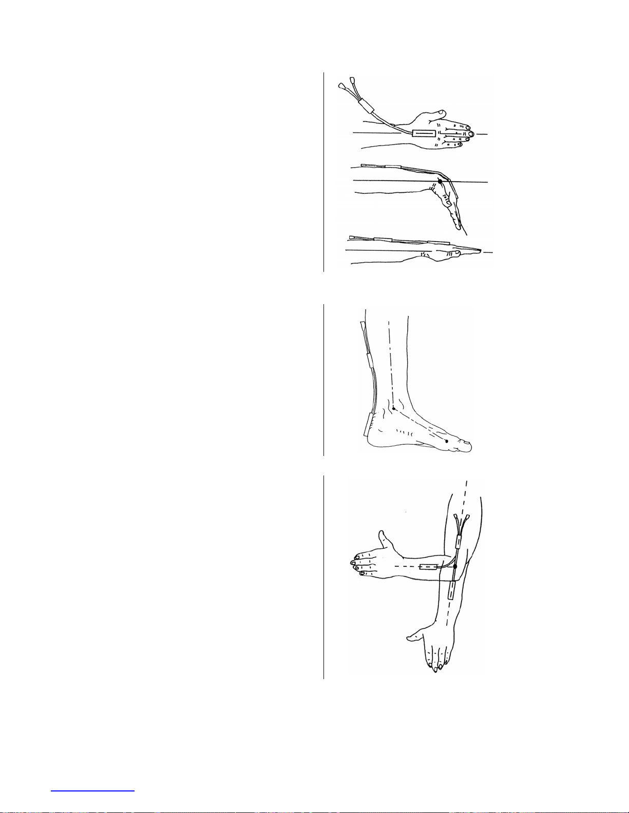
THE WRIST – TSD130A Goniometer
Attach the telescopic endblock to the back of the hand,
with the center axis of the hand and endblock coincident
(top of figure — viewed in the frontal plane).
While fully flexing the wrist (middle and bottom of
figure), extend the goniometer to Position 2 (as shown on
page
69) and attach the fixed endblock to the forearm so
that when viewed from the dorsal plane, the axes of the
forearm and endblock are coincident. The wrist may now
be flexed or extended, abducted or adducted, with the
goniometer freely sliding between Positions 1 and 2.
Measurement of flexion/extension is obtained from the
gray plug, and abduction/adduction is obtained from the
blue plug.
THE ARTICULAR COMPLEX OF THE FOOT –
TSD130A Goniometer
Attach the telescopic endblock to the back of the heel.
Extend the ankle to the maximum extension anticipated
during measurement, and attach the fixed endblock to the
posterior of the leg, with the goniometer in Position 1
(maximum length, as shown on page
69) so that the axes
of the leg endblock are coincident.
Flexion/extension of the ankle may now be monitored
using the gray plug and pronation/supination using the
blue marked plug.
THE ELBOW – TSD130B Goniometer
Attach the telescopic endblock to the forearm with the
center axis of the endblock coincident with the center axis
of the forearm. With the elbow fully extended, move the
goniometer to Position 2 (maximum length, as shown on
page
69) and attach the fixed endblocks to the upper arm,
with the center of the endblock and the center axis of the
upper arm coincident.
Now the elbow may be fully extended with the telescopic
endblock freely sliding between Positions 1 and 2.
Measurement of flexion/extension is obtained from the
blue marked plug, and the gray plug is redundant. Note
that the telescopic endblock is mounted on the half of the
forearm nearest to the elbow joint. Movements of
pronation and supination may be made and will affect the
measurement of flexion/extension by a small amount.
www.biopac.com 75
Page 76
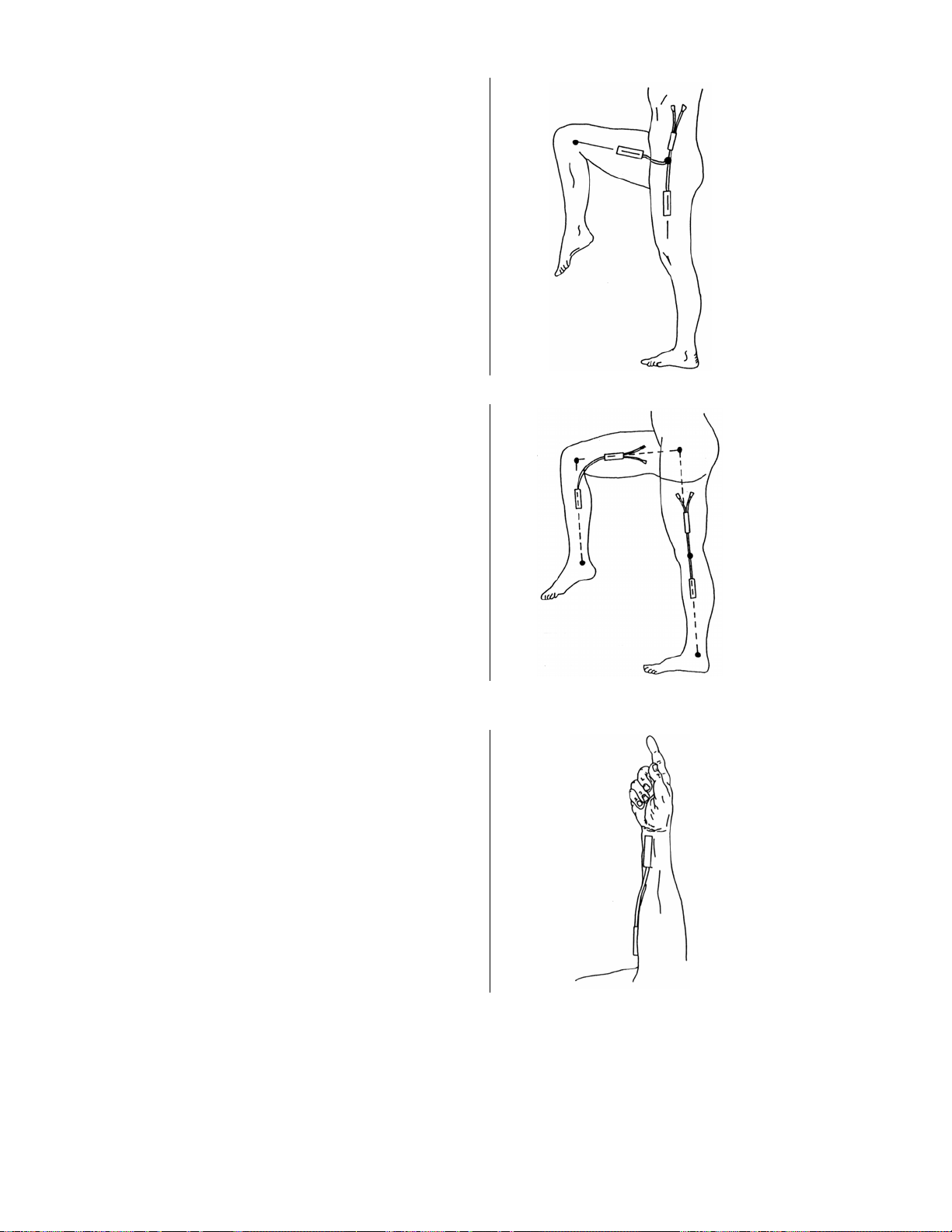
THE HIP – TSD130B Goniometer
Attach the fixed endblock to the side of the trunk in the
pelvic region. With the limb in the position of reference,
extend the goniometer to Position 2 (maximum length, as
shown on page
69) and attach the telescopic endblock to
the thigh, so that axes of the thigh and endblock coincide
(when viewed in the sagittal plane, as shown).
The thigh may now be flexed or extended, abducted or
adducted, with the goniometer sliding freely between
Positions 1 and 2. Measurements of flexion/extension are
obtained from the blue marked, and abduction/adduction
from the gray plug.
THE KNEE – TSD130B Goniometer
Mount the telescopic endblock laterally on the leg so the
axes of the leg and endblock coincide, when viewed in the
sagittal plane. With the leg fully extended in the position
of reference, extend the goniometer to Position 2
(maximum length, as shown on page
69) and attach the
fixed endblock to the thigh so the axes of the thigh and
endblock coincide.
The knee may now be flexed or extended with the
goniometer freely sliding between Positions 1 and 2.
Measurements of flexion/extension may be monitored
using the blue marked plug and varus/valgus may be
monitored using the gray plug.
FOREARM PRONATION /SUPINATION –
TSD130C or TSD130D Torsiometer
Attach the two endblocks of the torsiometer to the
forearm, with the slider mechanism approximately
midway between the two extremes.
Measurements of pronation/supination may now be made
from the gray plug. Movements of wrist flexion/extension
or radial/ulnar deviation will not effect the output.
76 MP System Hardware Guide
Page 77
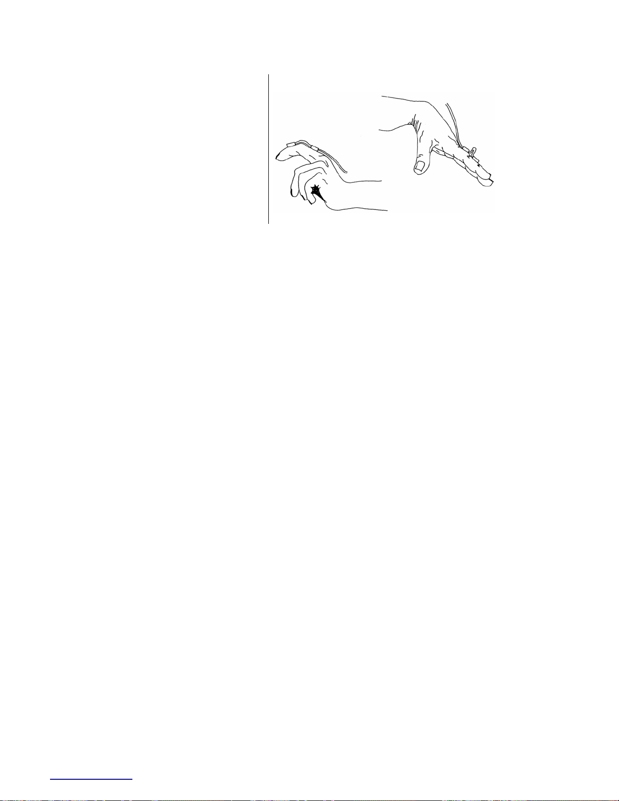
FINGERS AND TOES – TSD130E Goniometer
The TSD130E goniometer is a single axis
goniometer intended for use on fingers and
toes. Angles are measured by rotating one
endblock relative to the other about axis X-X
(as shown on page
69).
The goniometer is not designed to measure
rotations about Y-Y. Any attempt to bend the
unit in this way more than +/-20° from the
neutral position will result in reduced unit
life or failure. The goniometer does not
measure rotations about the axis Z-Z.
The unit is designed to fit over the joint to be measured and has extremely high flexibility to ensure
the instrument does not interfere with normal joint movement. One endblock is attached either side
of the joint.
Unlike the TSD130A and TSD130B series and “Z” series sensors, an “oxbow” shape is permitted
in the measuring element. This is not detrimental to the results and does not reduce life of sensor.
Care should be taken, however, that the minimum bend radius is not exceeded.
www.biopac.com 77
Page 78
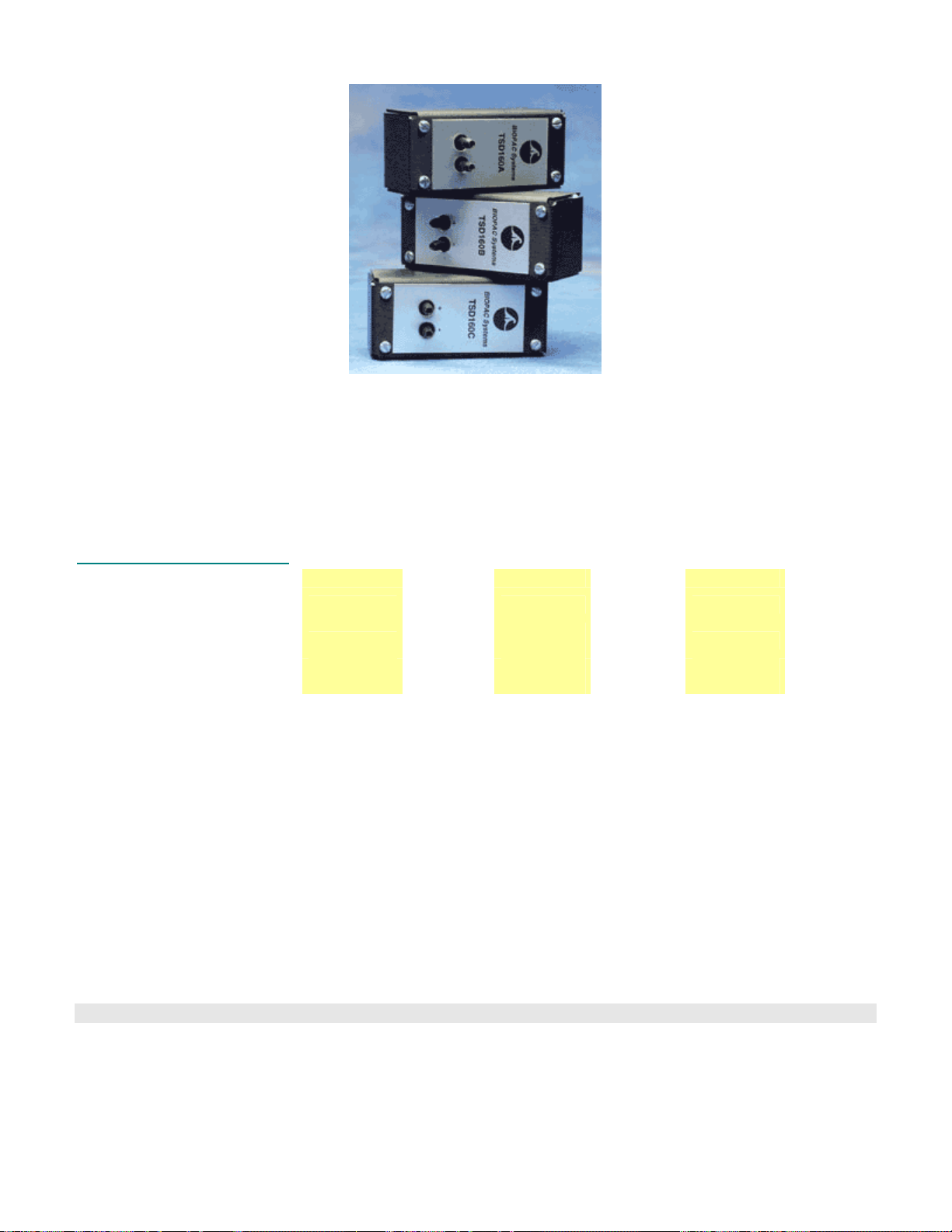
TSD 160 SERIES HIGH SENSITIVITY DIFFERENTIAL PRESSURE TRANSDUCERS
The TSD160 series differential pressure transducers are designed for low range pressure monitoring. The
transducers plug directly into the DA100C general-purpose differential amplifier. The differential pressure ports are
located on the front of the transducers and are easily connected to breathing circuits, pneumotachs or
plethysmograph boxes. These transducers are very useful for interfacing a variety of small animal pneumotachs or
plethysmographs to the MP System. The transducers are extremely sensitive and come in three ranges to suit a
number of different applications. RX137 heads connect to the TSD160A differential pressure transducer via
standard 3mm or 4mm ID tubing.
TSD160 Series Specifications
Operational Pressure:
Overpressure (max):
Voltage Output (normalized
to 1 volt excitation):
Warm-up Drift: ±50µV
Stability: ±100µV
Operating Temperature: 0°C to +50°C (compensated)
Storage Temperature: -40°C to +125°C
Combined Linearity
and Hysteresis Error: ±0.05%
Dynamic Response: 100 Hz
Connection Ports: Accepts 3 mm to 4.5 mm ID tubing
Dimensions: 8.3 cm (high) x 3.8 cm (wide) x 3.2 cm (deep)
Weight: 76 g
Interface: DA100C
Part TSD160A TSD160B TSD160C TSD160D TSD160E TSD160F
±2.5 cm H2O
±250 cm H2O
327.5 µV/cm
H2O
±12.5 cm
O
H
2
±380 cm
O
H
2
131 µV/cm
H2O
±25 cm H2O ±75 cm H2O ±350 cm H2O
±380 cm
H2O
65.5 µV/cm
H2O
±700 cm
H2O
21.9 µV/cm
H2O
±700 cm H2O
14.22 µV/cm
H2O
±1,000 cm
O
H
2
±4,200 cm
O
H
2
7.11 µV/cm
H2O
TSD160 Series Calibration
See DA100C Calibration options on page
45.
78 MP System Hardware Guide
Page 79
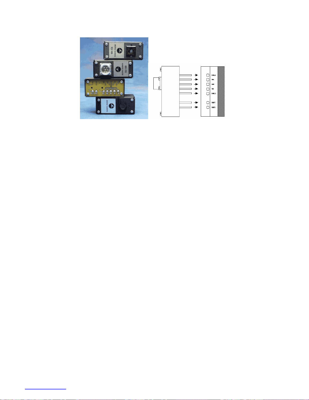
TCI SERIES TRANSDUCER CONNECTOR INTERFACES
TCI interface options TCI to DA100C Connection
The transducer connector interfaces (TCIs) adapt a variety of transducer types to the DA100C module. The front of
the TCI contains the appropriate connector while the rear has seven 2 mm pin jacks which plug directly into the
DA100C.Probes and transducers normally used with Grass, Beckman, World Precision Instruments and Lafayette
Instrument’s equipment can be used directly with the DA100C when used with the appropriate transducer connector
interface.
The TCIs match the DA100C to the transducer brands listed below. If no existing connector matches the required
equipment, BIOPAC will build a special TCI for users, or users can use the TCIKIT to build their own. Please call
or write BIOPAC with specific needs.
TCI100 Grass/Astromed transducers – 6 pin
TCI101 Beckman transducers – 5 pin
TCI102 World Precision Instrument transducers – 8 pin
TCI103 Lafayette Instrument transducers – 9 pin
TCI104 Honeywell transducers – 6 pin
TCI105 Modular phone jack connector – 4 pin (also used to interface NIBP100A)
TCI106 Beckman transducers – 12 pin
TCI107 Nihon Koden transducers – 5 pin
TCI108 Narco transducers – 7 pin
TCI109 Fukuda transducers – 8 pin
TCI110 Gould transducers – 12 pin: Discontinued Æ use Fogg Cable and an available BIOPAC TCI
TCI111 Liquid metal transducers – 2mm sockets (two)
TCI112 Hokanson transducers – 4 pin
TCIPPG1 PPG100C amplifier to Geer Photo-electric (IR) plethysmogram transducer – 7 pin
TCIKIT Build a customized adapter to the DA100C — see page
85
www.biopac.com 79
Page 80
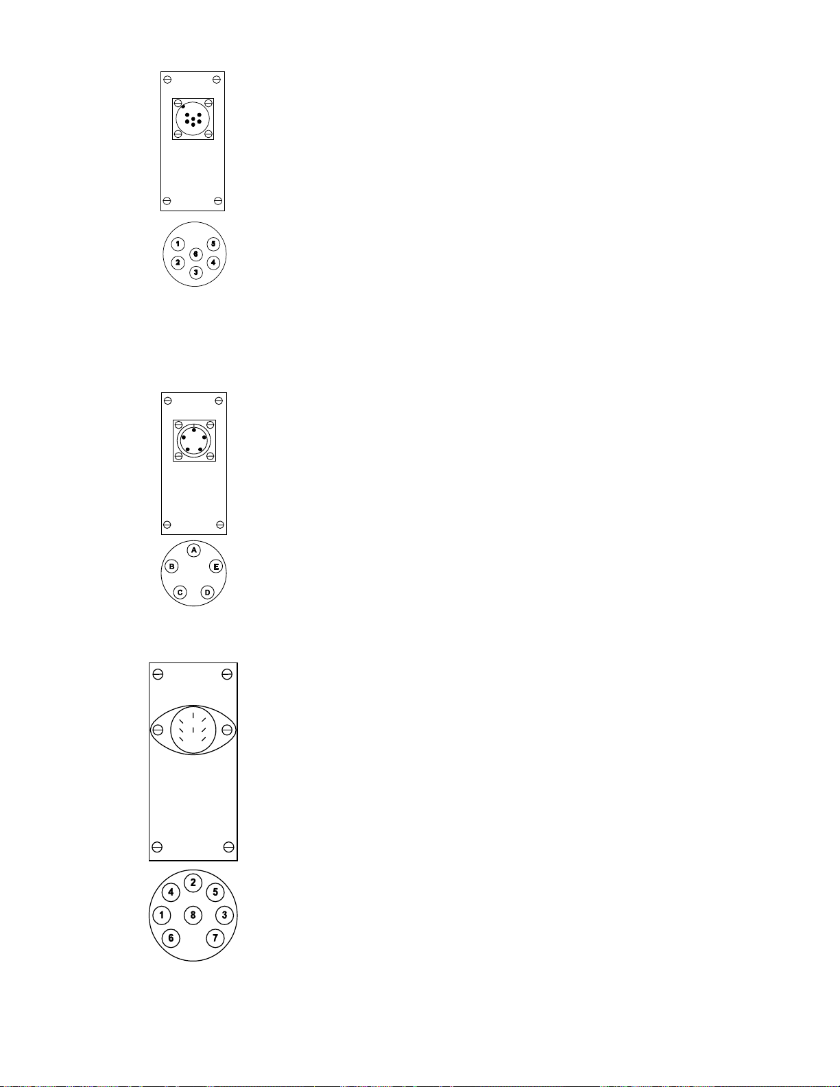
TCI100 Grass transducer interface
Pin Signal
1 VREF2 (Set to -1V)
2 VIN-
3 VIN+
4 VREF1 (Set to +1V)
6 GND
Connector ITT Cannon WK-F-32S
Typical VREF ±1V
TCI101 Beckman transducer interface
TCI102 WPI transducer interface
Pin Signal
A VIN-
B VIN+
C VREF1 (Set to +1V)
D VREF2 (Set to -1V)
E GND
Connector ITT Cannon CA-3102-E-14S-5S
Typical VREF ±1V
Pin Signal
1 VREF1 (Set to +5V)
2 VIN+
3 VIN-
4 VREF2 (Set to -5V)
Connector CUI Stack SDS-80J
Typical VREF ±5V
TCI103 Lafayette transducer
80 MP System Hardware Guide
Page 81
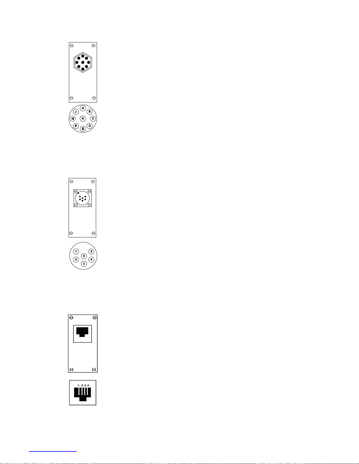
interface
Pin Signal
C VREF2 (Set to -5 V)
E GROUND
H VIN+
K VREF1 (Set to +5 V)
Connector Amphenol 12F-013
Typical VREF ± 5V
TCI104 Honeywell transducer interface
TCI105 Phone plug (RJ-11) transducer interface
Pin Signal
1 VREF2 (Set to -1 V)
2 VIN-
3 VIN+
4 VREF1 (Set to +1 V)
5 GND
Connector ITT Cannon WK-F-32S
Typical VREF ±1V
Pin Signal
1 VREF1 (Set to +3 V)
2 VIN +
3 VIN –
4 VREF2 (Set to -3 V)
Connector RJ-11 Phone plug
Typical VREF ±2 V DC
www.biopac.com 81
Page 82
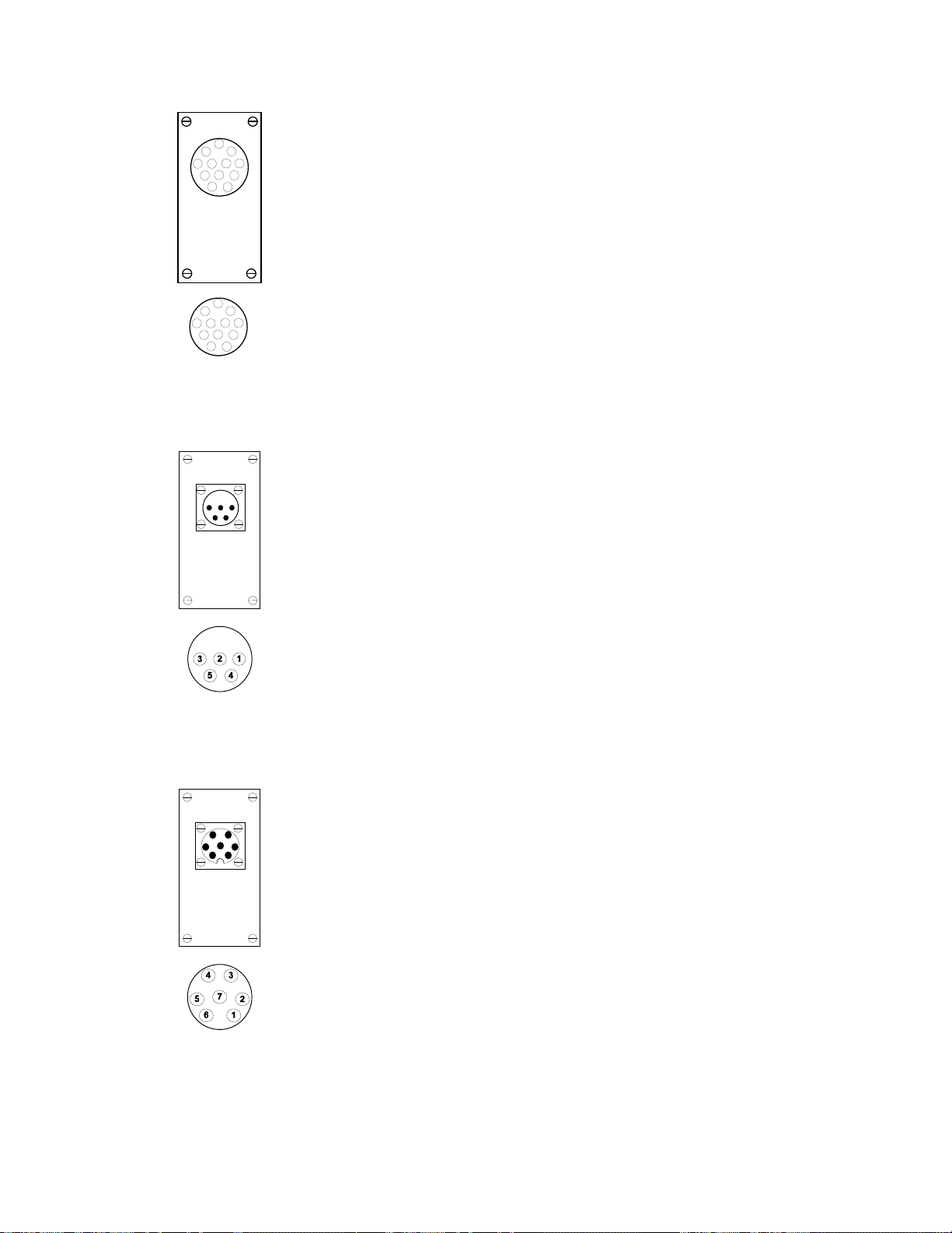
TCI106 Beckman (12-pin) transducer interface
B
A
DCE
FH
K
J
L
N
M
B
A
DCE
FH
K
J
L
N
M
Pin Signal
A VIN +
B VIN –
C VREF2 (-1 V)
D VREF1 (+1 V)
E Ground
Connector Amphenol 165-12
Typical VREF ±1 V
TCI107 Nihon Kohden transducer interface
TCI108 Narco (7-pin) transducer interface
Pin Signal
2 VIN+
3 VREF1 (+1 V)
4 VREF2 (-1 V)
5 VIN –
Connector JAE SRC-02A13-5S
Typical VREF ±1 V
Pin Signal
1 VIN+
2 VIN –
4 GND
5 (connect 1,600-ohm resistor
between pins 5 and 7)
6 VREF1 (+1 V)
7 VREF2 (-1 V)
Connector Amphenol 703-91T-3478-009
Typical VREF ±1 V
TCI109 Fukuda transducer
82 MP System Hardware Guide
Page 83
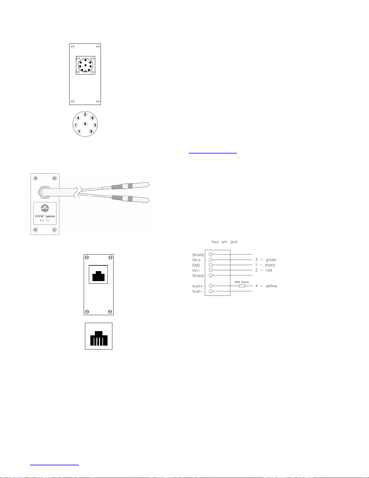
interface
Pin Signal
1 VIN+
3 VIN-
6 VREF2 (-1V)
7 VREF1 (+1V)
Connector Hirshmann MAS 8100
Typical VREF ±1 V
TCI110 Gould transducer interface
Discontinued –
TCI111 Liquid metal transducer interface
TCI112 Hokanson transducer interface
123 4
see options online
Connector: Signal
A (top) XDCR
B (bottom) XDCR
Connector Type: 2 mm socket (accepts
2mm pin XDCRs)
Pin Signal
+
1 Iex
2 VIN
3 VIN
4 Iex
+
–
–
Connector RJ-11 Phone plug
Typical Iex: 5 mA
www.biopac.com 83
Page 84
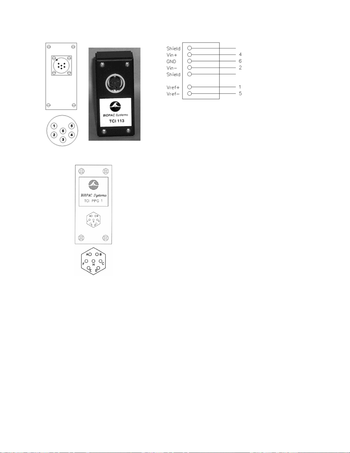
TCI113 Hugo Sachs/Harvard Apparatus Interface
TCIPPG1 PPG—Geer transducer interface
Six-pin female:
Pin Signal
A not used
B not used
C not used
D Ground
E VIN +
F +5 Vex
G not used
Connector Amphenol 7-pin
84 MP System Hardware Guide
Page 85
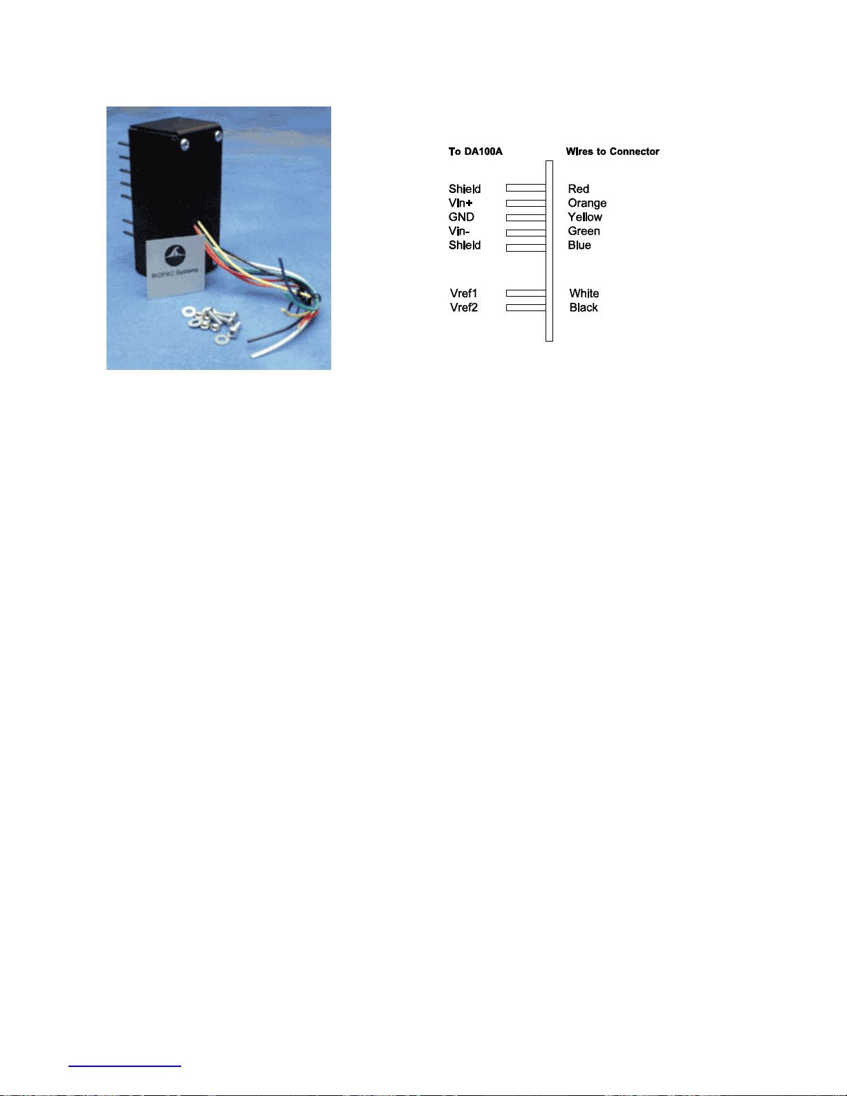
TCIKIT CUSTOM INTERFACE KIT
Build custom transducer connector interfaces for DA100C amplifier modules. The do-it-yourself TCI Kit includes
housing, PC board with 7 attached PIN plugs (2 mm) and instructions. The kits come partially assembled. Mount a
connector to the housing and solder wires to the pins.
The TCI case has two connector holes on the front, 0.44” and 0.75” in diameter. These sizes should accommodate
most connectors. The aluminum label is intended to cover up the unused hole. Color-coded wires have been
soldered to each of the seven DA100C input pins. They are connected as shown above.
Adapting the TCI
The following instructions are for adapting the TCI for any particular connection. A “Bulkhead Mount” connector is
the best type of connector to use.
1. Remove four screws from back of TCI so that the TCI PC board and case are separate.
2. Remove four connector-mounting screws from TCI case and set aside.
3. Check to see that your connector fits the TCI case. If not, the smaller (0.44”) hole can be enlarged using a hole
enlarging drill bit.
4. Clip off unused wires from the TCI PC board. Be very careful not to clip the ones you need.
5. Note that most connectors must be mounted from the outside of the case. This means that the wires should first
be routed through the appropriate hole, then soldered to the connector.
6. Solder the appropriate wires to the connector.
CAUTION! When you solder wires or components on the TCI PC board, be very careful not to desolder the
pre-aligned pin plugs. You may not be able to get them straight if you inadvertently desolder
them.
7. Bolt the connector to the case using the supplied 4-40 screws and nuts.
8. Bolt the TCI PC board to the TCI case.
9. Cover unused hole with supplied label.
www.biopac.com 85
Page 86
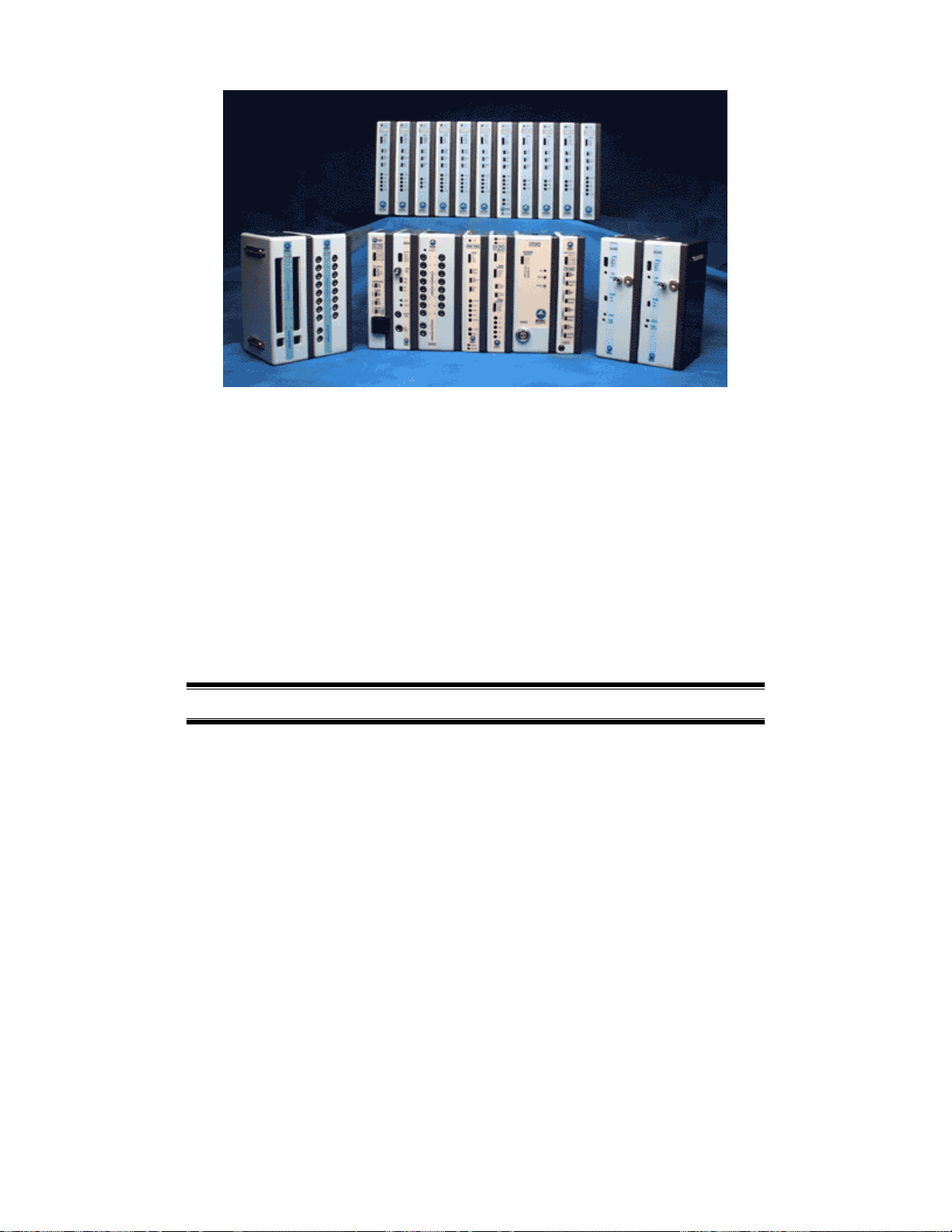
Chapter 4 Biopotential / Transducer Modules
100C series modules
The 100C series biopotential/transducer amplifier modules are single channel, differential input, linear amplifiers
with adjustable offset and gain. These modules are used to amplify smaller voltage signals coming from raw
electrodes and transducers (typically less than ±0.01 volt). In addition to amplifying signals, most of the 100C series
modules include selectable signal conditioning ability so that data may be filtered or transformed as it is being
collected.
Biopotential modules: ECG100C, EEG100C, EGG100C, EMG100C, EOG100C, ERS100C (specifications
start on page
Transducer modules: GSR100C; PPG100C; RSP100C; SKT100C (specifications start on page
Modules can be cascaded by snapping the modules together. Up to sixteen 100C series modules can be connected to
the MP System at any one time.
86)
107)
IMPORTANT
When cascading modules, it is important to remember that no two amplifiers may
be set to the same channel. If two connected amplifier modules are left on the
same channel, then contention will result and both amplifier outputs will give
erroneous readings.
86 MP System Hardware Guide
Page 87

Amplifier offset Set by the zero adjust control trim potentiometer near the top of the module. The
offset control can be used to adjust the zero point or “baseline” of a signal.
Gain Switch The four-position slide Gain switch controls sensitivity. Lower gain settings will amplify the
signal to a lesser extent than higher gain settings. If the signal plotted on the screen appears to be
very small for a given channel, increase the Gain for that particular channel. Conversely, if the
signal seems to be “cropped” at +10 Volts or −10 Volts, decrease the Gain.
Connections Transducers and electrodes connect to the amplifiers using Touchproof connectors.
Electrodes The biopotential amplifier modules use a three-electrode arrangement (VIN+, GND, VIN−).
Although certain applications may require different arrangements of electrodes and/or
transducers, some generalizations about electrode and transducer connections can be made.
Electrodes measure the electrical activity at the surface of the skin, and since electricity flows
from – to +, measuring the flow of a signal requires that there be (at least) one “-” electrode and
(at least) one “+” electrode. An additional electrode, a “ground” (or earth) electrode is used to
control for the general level of electrical activity in the body.
Leads Typically, electrode leads are used to connect individual electrodes to the xxx100C amplifier.
Most electrode leads are shielded, which means they introduce less noise than an unshielded lead.
A shielded electrode lead has an extra jack on one end that plugs into the SHIELD input on the
amplifier modules. A standard electrode lead configuration consists of two LEAD110S electrode
leads (one connected to the VIN + input and one to the VIN – input on the amplifier) and a single
LEAD110 (connected to the GND input on a biopotential amplifier).
Transducers Transducers, on the other hand, are not designed to measure electrical activity directly and
usually involve simpler connections. The transducers discussed in this manual translate physical
changes (in temperature, for instance) into electrical signals. Connections for individual
transducers are discussed in each section.
Channel The active channel is selected using the channel select switch on the top of the module. The
channel select switch can direct the amplifier output to one of sixteen possible MP System input
channels. Remember to make sure that each amplifier module is set to a unique channel.
Zero Adjust On input signals, a limited range in baseline level (DC offset) can be “zeroed out” using the zero
adjust potentiometer. Typically, the zero adjust will not have to be used (as it is preset at the
factory). However, some of the 100C series modules can measure DC signals and, in certain
circumstances, signal “zeroing” may be required.
Setup All of the 100C Series biopotential or transducer amplifiers incorporate specific gain, coupling
and filtering options that are appropriate for the biopotential type or transducer signal that
requires measurement. Generally, when an electrode or transducer is inserted into the
corresponding 100C series module, the amplifier will immediately produce a useful output, with
no user adjustments necessary.
Certain functionality is added to each module to optimize its performance with its intended signal
measurement. For example, all of the 100C series biopotential amplifiers incorporate a selectable
interference filter. When the interference filter is on, 50/60Hz interfering signals are suppressed.
Filters All of the 100C series amplifiers are constructed with filters that have a high degree of phase
linearity. This means the 100C series modules will filter signals with as little distortion as
possible. These modules also incorporate protection circuitry to limit input current in the event of
input signal overload.
Line Freq Line Frequency is set using the recessed switch boxes on the back of the amplifier module (50 Hz
= all switches down). See individual module sections for details.
www.biopac.com 87
Page 88
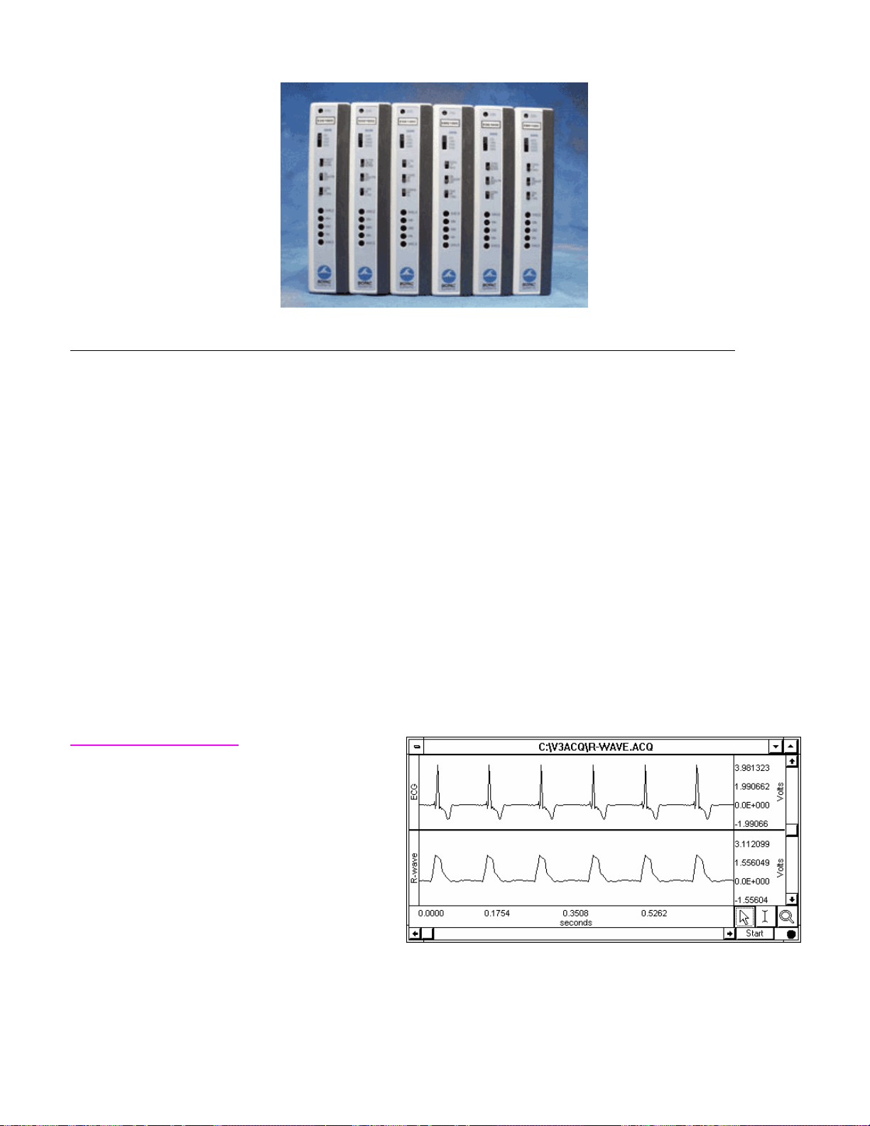
Biopotential Modules
Biopotential amplifier modules: ECG; EEG; EGG, EMG; EOG; ERS.
ECG100C – ELECTROCARDIOGRAM AMPLIFIER MODULE
The electrocardiogram amplifier module (ECG100C) is a single channel, high gain, differential input, biopotential
amplifier designed specifically for monitoring the heart’s electrical activity, and for use in the following
applications:
¾ Conventional electrocardiogram (12-lead ECG)
¾ Einthoven’s triangle potential measurement (3-lead ECG)
¾ Transverse-plane ECG measurement (V1 through V6)
¾ Vectorcardiogram measurement
The ECG100C will connect directly to any of BIOPAC Systems, Inc.’s series of Ag-AgCl lead electrodes. The best
choice for electrodes depends on the application, but typically the EL500 series (i.e., EL501, EL502, EL503) of
adhesive/disposable snap electrodes are used in conjunction with the LEAD110/LEAD110S pinch lead. If reusable
electrodes are required, the EL258 is typically used; when using EL258 electrodes, you will also need adhesive
disks (ADD208) and electrode gel (GEL100). Use two shielded electrodes (EL208S) for the signal inputs and one
unshielded electrode (EL258S) for the ground.
The ECG100C has built in drive capability for use with shielded electrode leads. If high bandwidth (resolution)
ECG measurements are required, then shielded electrode leads are recommended. When the interference filter is
switched on, shielded leads are typically not necessary. The ECG100C is designed to pass the ECG signal (P, Q, R,
S, T waves) with minimal distortion.
R-wave detector function
The ECG100C has an additional R-wave detector
function. When enabled, the output signal will
produce a smoothed positive peak every time the
R-wave is detected.
This graph illustrates ECG data recorded with the
ECG100C. The top waveform is a raw ECG wave,
and the bottom waveform is the same signal
processed using the R-wave detector in the
ECG100C module.
This function is extremely useful for rate
calculations when a well-defined peak is desired.
Enabling the R-wave detector is useful for calculating BPM and IBI, as it tends to remove any components of the
waveform that might be mistaken for peaks.
¾ Chaos investigations (heart rate variability)
¾ Heart arrhythmia analysis
¾ Exercise physiology studies
88 MP System Hardware Guide
Page 89
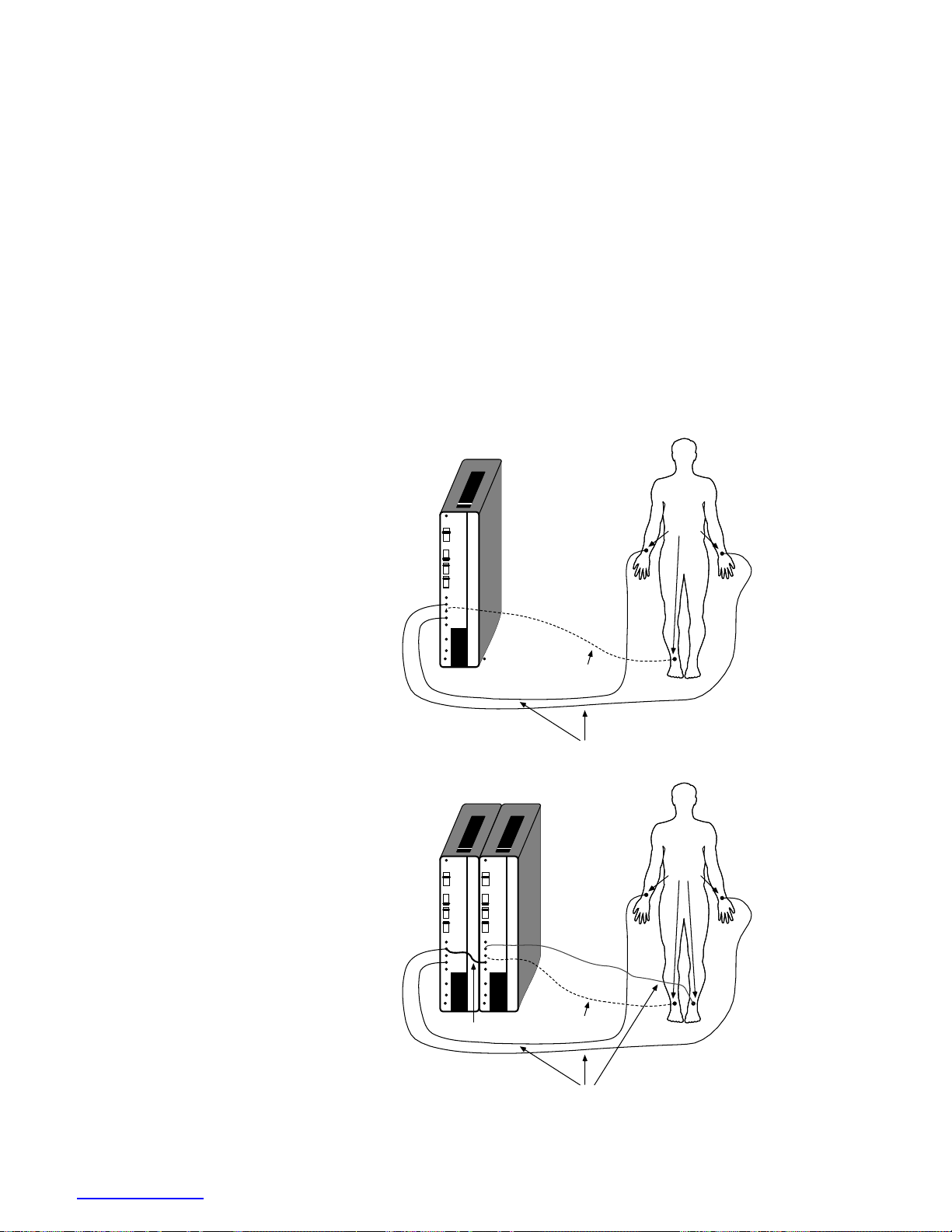
The R-wave detector circuitry consists of:
17Hz band pass filter with Q = 5
Full wave rectifier
10.0Hz, three pole, low pass filter with Q = 0.707
These settings are optimized for ECG data sampled at 250 Hz or faster. For data sampled at less than 250 Hz, you
may want to set the low pass filter to 5 Hz.
Recording a 12-lead ECG
For full, simultaneous, 12-lead ECG recording, eight ECG100C amplifiers are required, along with a
WT100C Wilson Terminal (see page
III, aVR, aVL and aVF, while the remaining six ECG100C are used to generate the six precordial leads.
To perform a standard 12-lead ECG recording using only three ECG100C amplifiers, use the TSD155C
(page
91). The TSD155C multi-lead ECG cable is 3 meters long and incorporates a built-in Wilson
Terminal for simultaneous recording of Leads I, II, III, aVR, aVL, aVF and one (movable) precordial lead
[V1, V2, V3, V4, V5 or V6].
91). Two of the ECG100C are used to simultaneous record Leads I, II,
This figure shows the electrode
connections to the ECG100C for the
measurement of Lead I. Signals from this
electrode montage can be used to calculate
BPM (or IBI) and general-purpose ECG
applications.
This figure shows the electrode
connections to two ECG100C modules for
recording a standard two lead ECG (Lead
I and Lead III). Although only two
channels are directly acquired, Lead II can
be computed (either on-line or after the
fact) by summing Lead I and Lead III. For
this setup, the GND input on Lead I is
internally connected to the GND input on
Lead III, and the VIN+ on Lead I is
connected to the VIN- on Lead III via a
JUMP100C jumper lead.
ZERO
ADJ
GAIN
500
1000
2000
5000
R WAV
NORM
ON
FILTER
OFF
ON
HIPASS
OFF
SHIELD
VIN+
GND
VIN-
SHIELD
ECG100
ZERO
ADJ
GAIN
500
1000
2000
5000
R WAV
NORM
ON
FILTER
OFF
ON
HIPASS
OFF
SHIELD
VIN+
GND
VIN-
SHIELD
ECG100
JUMP100
ZERO
ADJ
GAIN
500
1000
2000
5000
R WAV
NORM
ON
FILTER
OFF
ON
HIPASS
OFF
SHIELD
VIN+
GND
VIN-
SHIELD
ECG100
RIGHT LEFT
EL503
LEAD100
LEAD100S
RIGHT LEFT
EL503
LEAD100
LEAD100S
www.biopac.com 89
Page 90
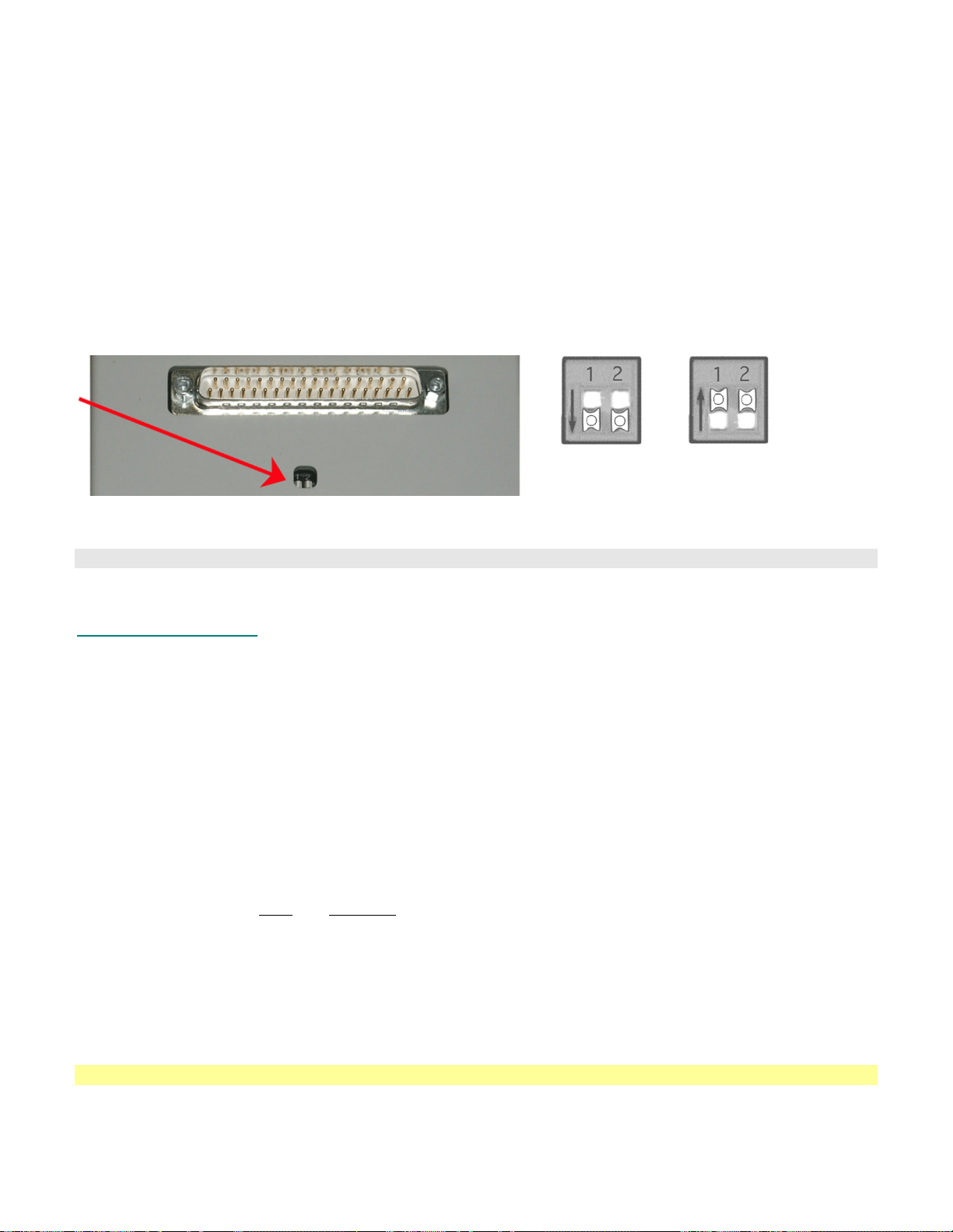
Frequency Response Characteristics
The ECG100C includes a high pass filter that is used to stabilize the ECG baseline. When the HP switch is set to
1.0Hz, P and T wave amplitudes will be reduced somewhat, but the QRS wave will be virtually unchanged. The HP
switch is usually ON when using the ECG100C for rate measurements only or when monitoring the ECG of an
active subject.
The 0.05Hz and 1Hz lower frequency response settings are single pole roll-off filters.
Modules can be set for 50Hz or 60Hz notch options to match the wall-power line frequency of the destination
country. The proper setting reduces noise from interfering signals when the notch filter is engaged. Generally, wallpower line frequency is 60Hz in the United States and 50Hz in most of Europe; contact BIOPAC if you are unsure
of your country’s line frequency. To reset the line frequency setting, adjust the bank of switches on the back of the
amplifier module.
Line Frequency switch bank is on the back of the amplifier 50Hz 60Hz
See the sample frequency response plots beginning on page
Both switches
DOWN
Both switches
UP
241: 35Hz LPN option (with 50Hz notch enabled),
100Hz LP option, and 35Hz LPN option (with 60Hz notch enabled)
ECG100C Calibration
The ECG100C is factory set and does not require calibration. To confirm the accuracy of the device, use the
CBLCALC.
ECG100C Specifications
Gain: 500, 1000, 2000, 5000
Output Selection: Normal, R-wave indicator
Output Range: ±10V (analog)
Frequency Response Low Pass Filter: 35Hz, 150Hz
High Pass Filter: 0.05Hz, 1.0Hz
Notch Filter: 50dB rejection @ 50/60Hz
Noise Voltage: 0.1µV rms – (0.05-35Hz)
Signal Source: Electrodes (three electrode leads required)
Z (input) Differential: 2MΩ
Common mode: 1000MΩ
CMRR: 110dB min (50/60Hz); see Shield Drive Operation on page
241
CMIV–referenced to Amplifier ground: ±10V
Mains ground: ±1500 VDC
Input Voltage Range: Gain
Vin (mV)
500 ±20
1000 ±10
2000 ±5
5000 ±2
Weight: 350 grams
Dimensions: 4cm (wide) x 11cm (deep) x 19cm (high)
See also: JUMP100C and MEC series
90 MP System Hardware Guide
Page 91
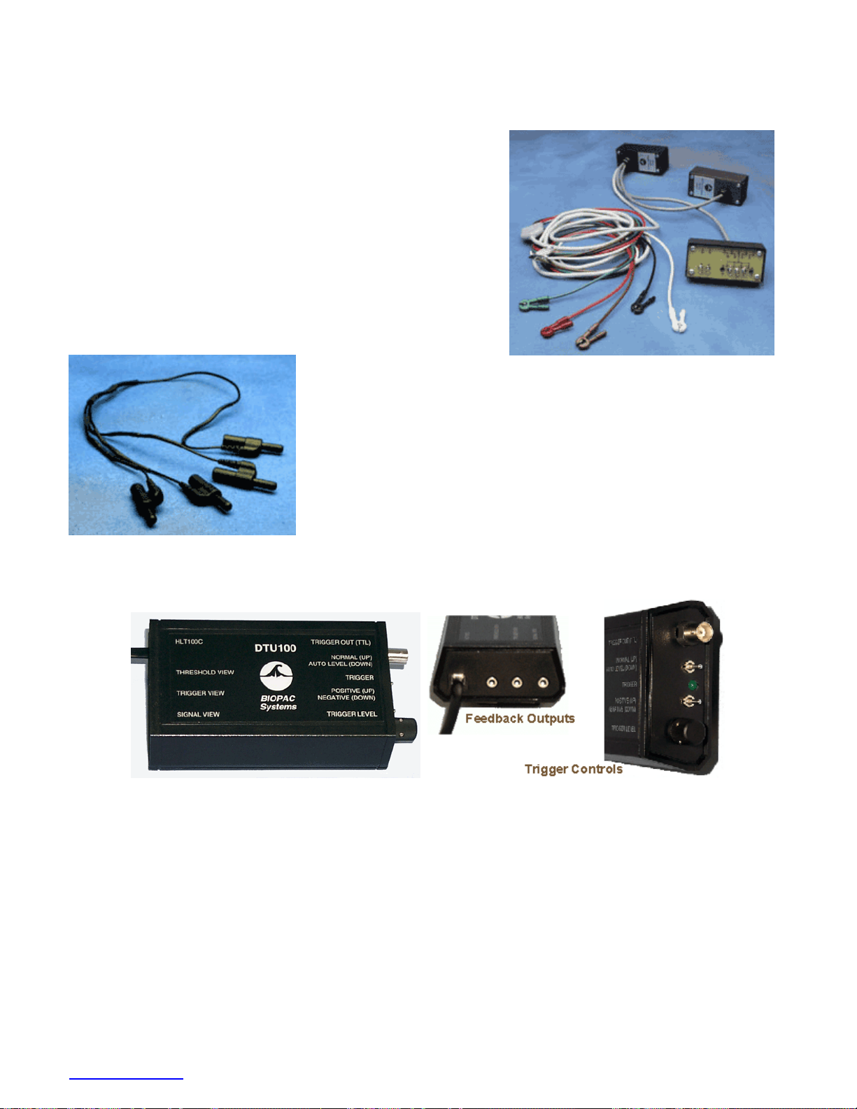
TSD155C MULTI-LEAD ECG CABLE
To record 12-lead ECG with a movable chest lead, use the TSD155C
The TSD155C multi-lead ECG cable is 3 meters long and
incorporates a built-in Wilson Terminal for simultaneous recording
of Leads I, II, III, aVR, aVL, aVF and one (movable) precordial lead
[V1, V2, V3, V4, V5 or V6].
The TSD155C is used for performing a standard
12-lead ECG recording using only 3 ECG100C amplifiers.
TEL100 Compatibility: SS29, page
227
WT100C WILSON TERMINAL for the ECG100C
The WT100C is used to create a virtual reference electrode when measuring
the transverse plane (i.e., precordial) ECG components [V1, V2, V3, V4, V5,
and V6]. The virtual reference is created by the summation of the Right Arm
(RA), Left Arm (LA) and Left Leg (LL) electrode leads. To measure all six
transverse plane components, six ECG100C amplifiers are required. Use five
of the JUMP100C jumper connectors to tie together the reference (Vin-)
inputs of these amplifiers. This common reference connects to the virtual
reference created by the WT100C.
DTU100 DIGITAL TRIGGER UNIT
Digital Trigger (MRI Trigger)
Use the DTU100 Digital Trigger Unit to trigger an MRI System with the occurrence of the R-wave present in
animal (high frequency) ECG data. The DTU100 provides high-level (3000 v) isolation between the MP System
and external equipment; the DTU100 is always used with the HLT100C module. This isolation is very important to
maintain both subject safety and high quality signal recording. This external hardware module can accept data from
any analog output associated with an MP System and convert that analog signal into a TTL compatible trigger
suitable for synchronizing with external devices.
For the DTU100, “Analog output” means:
1) Analog output associated with any MP module (DA100C, ECG100C, etc) that is sending data to an MP
System on Analog Input channels 1–16.
2) Analog output coming from the MP system via one of its D/A converters on Analog Output channel 0–1.
www.biopac.com 91
Page 92

DTU100 CONTROLS
HLT100C The DTU100 is always used with the HLT100C module. Use the RJ-11 straight through
cable provided by BIOPAC to plug the DTU100 into the HLT100C.
Feedback Views The DTU100 incorporates three feedback outputs that can be monitored on the MP
System to properly set the threshold (trigger) level and required Trigger Out polarity for
any type of analog input. Use a 3.5 mm mono phono cable (CBL100) to connect the
respective line to an unused MP system input channel.
Threshold View Shows the Threshold (Trigger) Level
Trigger View Shows the Trigger Output as sent to the external equipment.
Signal View Shows the analog input signal as sent to the DTU100.
Trigger Out Connect a TTL line with BNC female connector between the DTU100 and your trigger
device.
Normal/Auto Level The DTU100 incorporates an optional Automatic Level control circuit. The Automatic
Level control circuit will expand or compress the analog input signal to fit inside of a ±5v
range.
Normal — use if the analog input signal is clearly defined.
Auto Level — use if the analog input signal has a widely varying baseline or
significant change in amplitude from one desired trigger point to the next; or you can
try to improve signal definition.
Trigger The Trigger LED (green) lights up whenever the Trigger Out signal goes high.
Positive/Negative If analog data is above the threshold setting the DTU100 output can be set to either high
(+5v) or low (0.0v). When analog data drops below the threshold value the output will be
the opposite level.
Trigger Level Select a trigger level (or threshold) that will fire when analog data reaches that threshold.
SYNCHRONIZATION
To synchronize an MRI System with the occurrence of the R-wave, record animal (high frequency) ECG data on an
ECG100C amplifier and direct the output to an analog input channel on the MP100/150 Unit.
a) Plug the DTU100 into channel 1 of the analog channels section of the HLT100C module.
b) Use CBL100 cables to connect the Threshold, Trigger and/or Signal View to unused inputs on the
UIM100C, if required.
c) Connect the Trigger Out (TTL) line to the MRI system requiring synchronization to the R-wave of the
ECG.
d) If the R-Wave is a clearly defined peak, run the DTU100 in Normal mode. If the R-wave is not always
predominant, consider operating the DTU100 in Auto Level mode, or change the location of ECG leads on
the subject to obtain a better-defined R-wave peak.
e) Adjust the Trigger Level potentiometer to obtain a Trigger Signal. Change the Trigger Out polarity to
Positive or Negative as required for the MRI equipment. Verify proper operation by noting the periodic
lighting of the green Trigger LED. This LED should light briefly whenever the R-wave is detected.
92 MP System Hardware Guide
Page 93
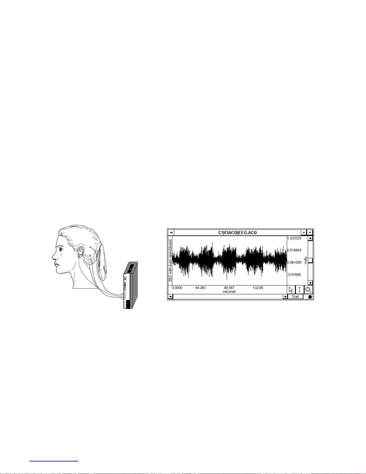
EEG100C – ELECTROENCEPHALOGRAM AMPLIFIER MODULE
The electroencephalogram amplifier module (EEG100C) is a single-channel, high-gain, differential input,
biopotential amplifier designed specifically for monitoring the neuronal activity of the brain. The EEG100C is
designed for use in the following applications:
Conventional EEG (16 channel, unipolar or bipolar) Sleep studies
Epilepsy investigations Evoked responses
Tumor pathology studies Cognition studies
The EEG100C will connect directly to any of BIOPAC Systems, Inc.’s series of Ag-AgCl lead electrodes.
Typically, EL503 electrodes are recommended for evoked response measurements. Use two shielded electrodes
(LEAD110S) for the signal inputs and one unshielded electrode (LEAD110) for ground. If hair is present,
disposable electrodes don’t work very well for scalp attachment, and you should use electrode gel (GEL100) and
®
tape the electrode lightly in place or use a conductive adhesive paste (like Ten20
or Collodion HV
The EEG100C has built-in drive capability for use with shielded electrode leads. If high bandwidth (resolution)
EEG measurements are required, then shielded electrode leads are recommended. When the interference filter is
switched on, shielded leads are typically not necessary.
This module is designed to pass the EEG signal ranges (Delta, Theta, Alpha, Beta, and Gamma) with minimal
distortion. In addition, the EEG100C has a built-in Alpha wave detector. When enabled, the output signal will
produce a smoothed wave with peaks that indicate points of maximum Alpha activity. The Alpha wave detector
consists of a highly selective, six pole, 8-13Hz bandpass filter, followed by a full wave rectifier, followed by a 6Hz,
three pole, low pass filter.
®)
.
Bipolar EEG electrode placement
ZERO
ADJ
GAIN
5000
10000
20000
50000
ALPHA
NORM
ON
FILTER
OFF
SHIELD
VIN+
GND
VIN-
SHIELD
EEG100
Bipolar connection to the occipital lobe
EEG waveform with eyes closed then opened
The illustration above shows a bipolar connection to the occipital lobe; to make a unipolar connection, relocate the
VIN- electrode to the earlobe (where GND is attached). The graph indicates the change in the occipital EEG when
eyes are closed and opened. The data is shown compressed, but can easily be expanded to show waveform
differences in greater detail.
Frequency Response Characteristics
The 0.1Hz and 1Hz lower frequency response settings are single pole, roll-off filters.
Modules can be set for 50Hz or 60Hz notch options to match the wall-power line frequency of the destination
country. The proper setting reduces noise from interfering signals when the notch filter is engaged. Generally, wallpower line frequency is 60Hz in the United States and 50Hz in most of Europe; contact BIOPAC if you are unsure
of your country’s line frequency. To reset the line frequency setting, adjust the bank of switches on the back of the
amplifier module.
www.biopac.com 93
Page 94
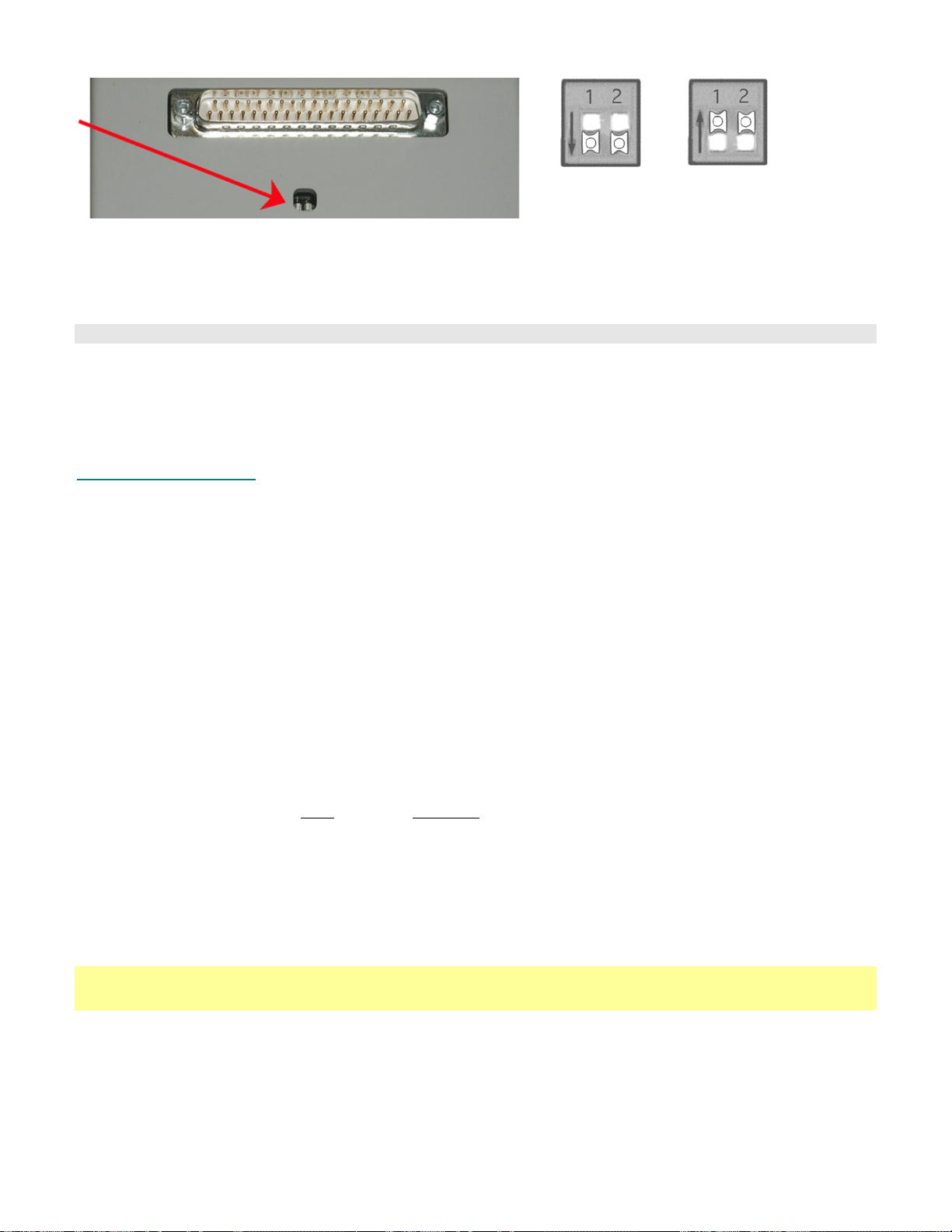
Line Frequency switch bank is on the back of the amplifier 50Hz 60Hz
See the Frequency response Plots beginning on page
Both switches
DOWN
Both switches
UP
241: 35Hz LPN (with 50Hz notch enabled)
35Hz LPN (with 60Hz notch)
100Hz LP option
EEG100C Calibration
The EEG100C is factory set and does not require calibration. To confirm the accuracy of the device, use the
CBLCALC.
Hardware settings are based on line frequency, which varies by country. To confirm that line frequency is set
correctly for your country, check the switches on the back panel of the amplifier.
EEG100C Specifications
Gain: 5000, 10000, 20000, 50000
Output Selection: Normal, Alpha Wave indicator
Output Range: ±10V (analog)
Frequency Response
Low Pass Filter: 35Hz, 100Hz
High Pass Filter: 0.1Hz, 1.0 Hz
Notch Filter: 50dB rejection @ 50/60Hz
Noise Voltage: 0.1µV rms – (0.1–35Hz)
Signal Source: Electrodes (three electrode leads required)
Z (input)
Differential: 2MΩ
Common mode: 1000MΩ
CMRR: 110dB min (50/60Hz); see Shield Drive Operation on page
241
CMIV—referenced to
Amplifier ground: ±10V
Mains ground: ±1500 VDC
Input Voltage Range: Gain
Vin (mV)
5000 ±2
10000 ±1
20000 ±0.5
50000 ±0.2
Weight: 350 grams
Dimensions: 4cm (wide) x 11cm (deep) x 19cm (high)
See also: JUMP100C
MEC series
94 MP System Hardware Guide
Page 95
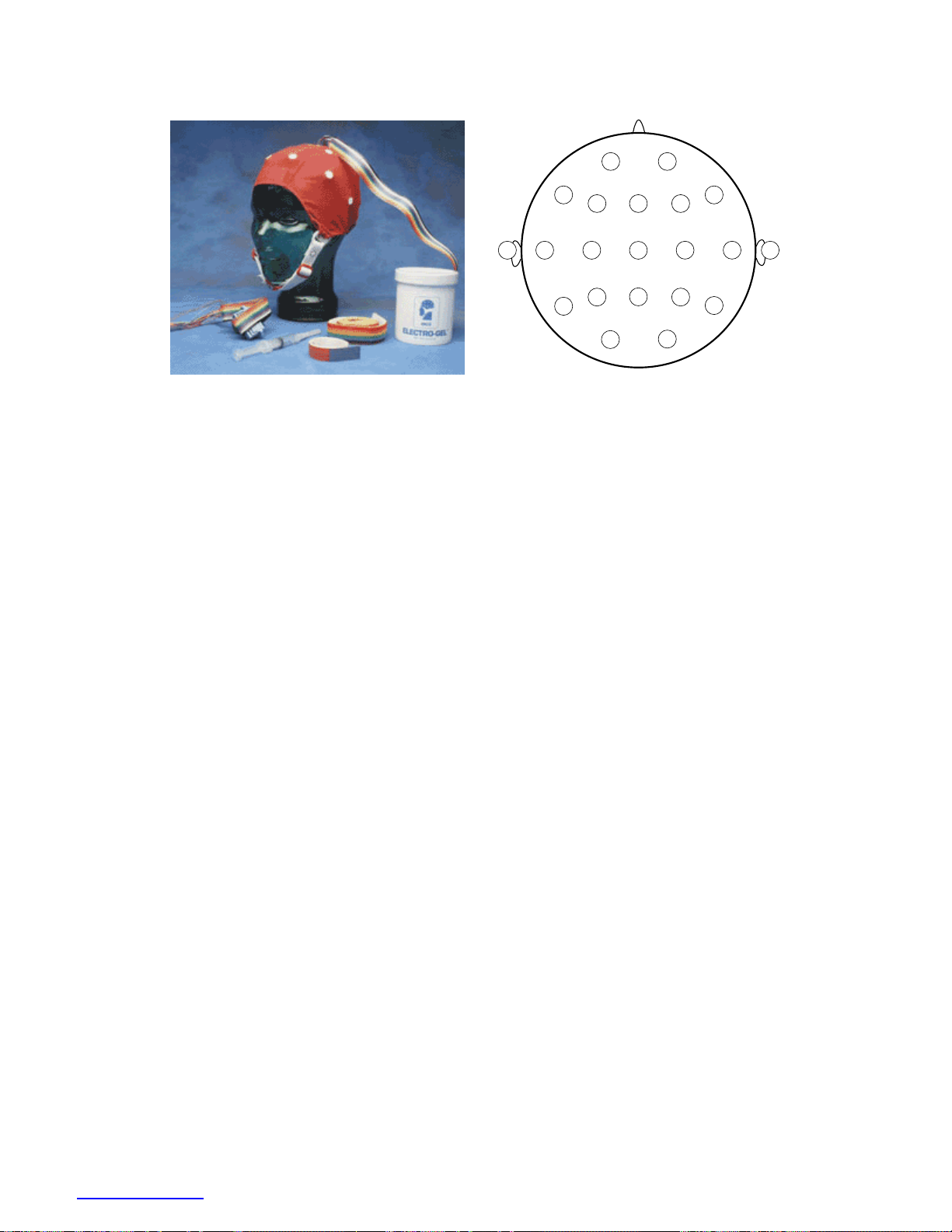
CAP100C ELECTRODE CAP
F
p
F
1
p
2
F
7
T
A
3
1
T
5
F
F
C
3
P
z
3
C
z
P
z
3
O
1
O
F
8
F
4
C
P
2
T
4
4
T
6
A
4
2
Electrode cap (CAP100C) International 10-20 electrode montage
The CAP100C is a fabric cap with recessed tin electrodes attached to the Lycra-type fabric. The electrodes are prepositioned in the International 10-20 montage (shown above). The standard (medium) electrode cap fits most
subjects over age five; infant, small, and large caps are also available.
Leads from the electrode cap terminate in 2-mm pin plugs, which are typically connected to inputs on the
EEG100C. Since leads are available for all electrodes, unipolar or bipolar montage recordings can be obtained. The
electrode cap comes with two ground electrodes, and can also be used for evoked potential investigations (such as
ABR).
www.biopac.com 95
Page 96
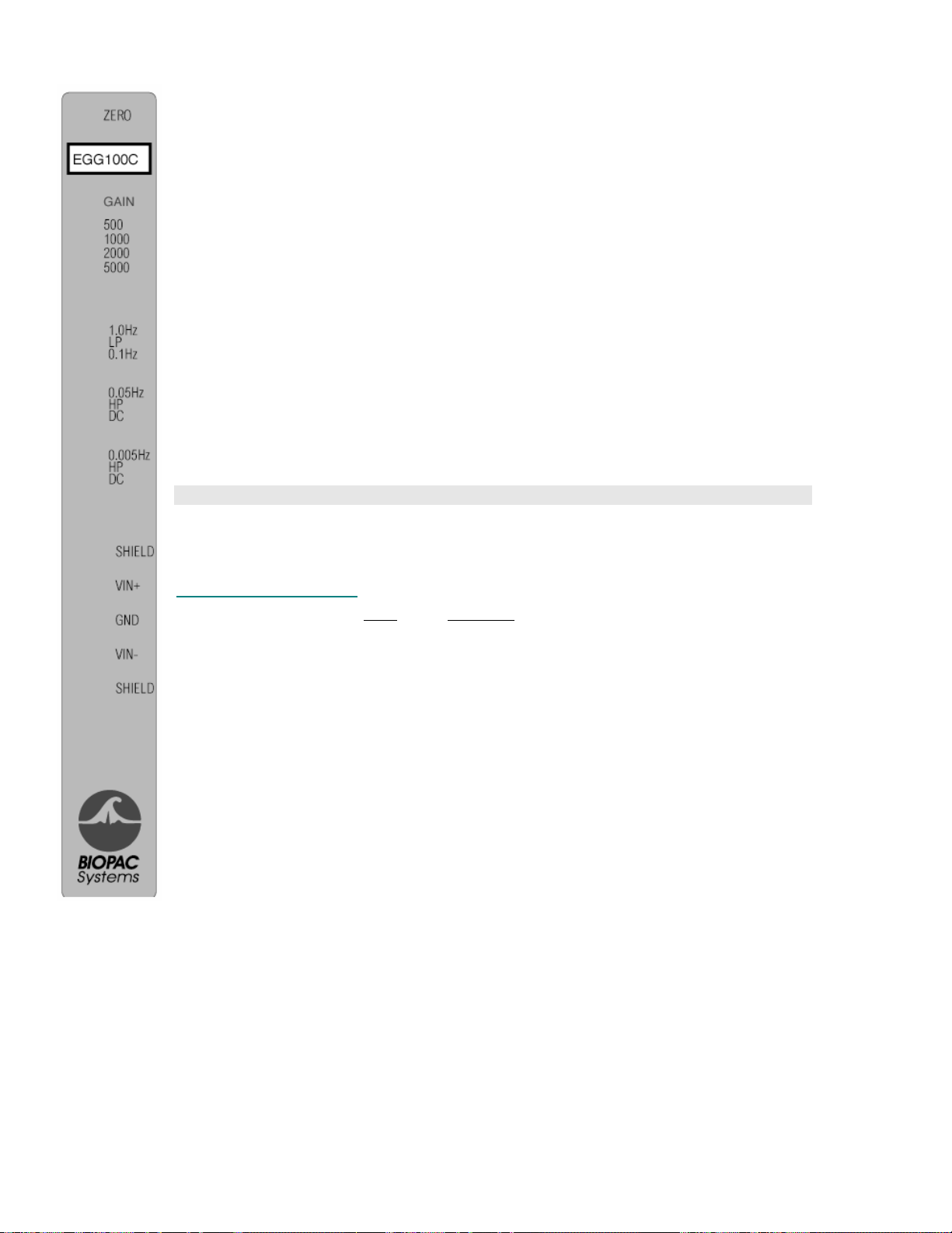
EGG100C – ELECTROGASTROGRAM AMPLIFIER MODULE
The EGG100C amplifies the electrical signal resulting from stomach and intestinal smooth
muscle activity. The amplifier monitors the DC potential on the skin surrounding, or surface
of, the intestine and stomach, which is indicative of the degree of slow wave contraction.
The amplifier permits DC coupling to electrodes for signal amplification and presentation
without discernible decay.
The gastric slow wave (ECA) originates in the proximal stomach and propagates distally
towards the pylorus. For recording, place multiple surface electrodes on the abdomen along
the gastric axis and connect them to respective EGG100C amplifiers that have a common
reference electrode placed near the xiphoid process. For consistent electrode-to-electrode
spacing, use the EL500 dual electrodes with LEAD110 leads. For extremely tight electrodeto-electrode spacing, use the EL254 or EL258 reusable Ag-AgCl lead electrodes. The
signals amplified at each electrode will be displayed on consecutive channels in
AcqKnowledge.
Frequency Response Characteristics
Modules can be set for 50 or 60Hz notch options, depending on the destination country.
The 0.005Hz and 0.05Hz lower frequency response settings are single pole, roll-off filters.
See the Frequency Response Plots beginning on page
EGG100C Calibration
The EGG100C is factory set and does not require calibration. To confirm the accuracy of
the device, use the CBLCALC.
EGG100C Specifications
Gain & Input Voltage: Gain
500 ±20
1000 ±10
2000 ±5
Output Range: ±10V (analog)
Frequency Response
Low Pass Filter: 0.1Hz, 1Hz
High Pass Filter: DC, 0.005Hz, 0.05Hz
Notch Filter: 50dB rejection @ 50/60Hz
Noise Voltage: 0.1µV rms – (0.005-1.0Hz)
Signal Source: Electrodes (three electrode leads required)
Z (input)
Differential: 2MΩ
Common mode: 1000MΩ
CMRR: 110dB min (50/60Hz); see Shield Drive Operation on page
CMIV—referenced to
Amplifier ground: ±10V
Mains ground: ±1500 VDC
Weight: 350 grams
Dimensions: 4cm (wide) x 11cm (deep) x 19cm (high)
Vin (mV)
5000 ±2
241: 0.1Hz LP, 1Hz LP.
241
96 MP System Hardware Guide
Page 97
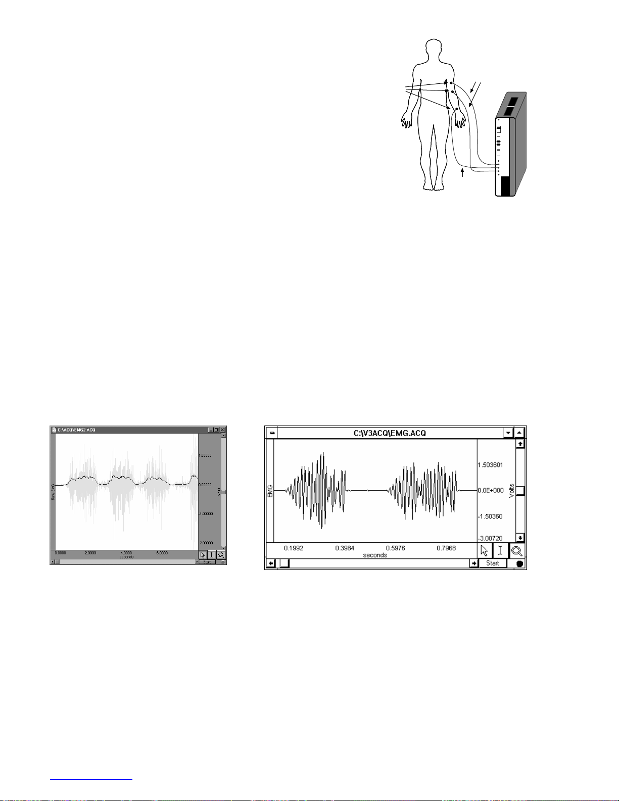
EMG100C – ELECTROMYOGRAM AMPLIFIER MODULE
LEAD100
LEAD100S
ZERO
ADJ
GAIN
500
1000
2000
5000
INTEG
NORM
ON
FILTER
OFF
SHIELD
VIN+
GND
VIN-
SHIELD
EMG100
The electromyogram amplifier module (EMG100C) is a single-channel, high-
EL503
gain, differential input, biopotential amplifier designed specifically for
monitoring muscle and nerve response activity. The EMG100C is
designed for use in the following applications:
Conventional bipolar EMG measurement
Biomechanics
Nerve conduction measurement
Muscular reflex studies
Motor unit potential measurement
Electrode connections to the EMG100C to
measure EMG activity from the arm biceps
The EMG100C will connect directly to any of BIOPAC Systems, Inc.’s series of Ag-AgCl lead electrodes. The best
choice for electrodes depends on the application, but typically, the EL503 adhesive/disposable snap electrodes are
used in conjunction with the LEAD110S pinch lead. If reusable electrodes are required, the EL508S is typically
used; when using EL508S electrodes, you also need adhesive disks (ADD208) and electrode gel (GEL100). Use
two shielded electrodes (LEAD110S/EL503 or EL508S) for the signal inputs and one unshielded electrode
(LEAD110/EL503 or EL508) for ground.
The EMG100C has built-in drive capability for use with shielded electrode leads. Shielded leads are typically
required, as the EMG100C has a frequency response that extends through the 50/60Hz interference bands. The
EMG100C is designed to pass EMG signals and signals associated with nerve responses.
The EMG100C incorporates a variety of filtering options to optimize the amplifier performance when recording
from either surface or needle electrodes, and when recording from either muscle or nerves. For instance, when
recording EMG (muscle) from surface electrodes, the 10Hz to 500Hz bandwidth setting could be used, but when
recording nerve propagation times, the 100Hz to 5,000Hz bandwidth setting could be used.
This graph shows a typical raw EMG
recording. Waveform peaks indicate points
of peak muscle activity.
This graph shows raw EMG and integrated EMG.
To integrate EMG in real-time, set up a calculation channel
in AcqKnowledge using the Integrate function with
Rectify checked ON. In this case, this waveform would be
augmented by a smoothed curve following the positive
envelope of the EMG signal.
www.biopac.com 97
Page 98
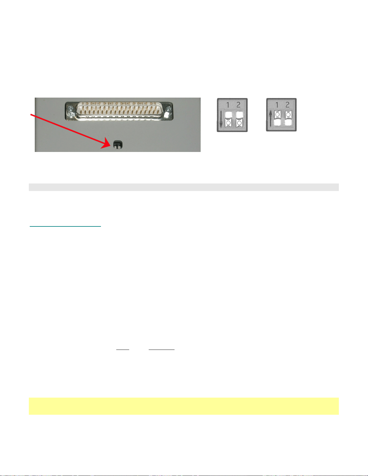
Frequency Response Characteristics
The 1Hz and 10Hz lower frequency response settings are single pole roll-off filters.
Modules can be set for 50Hz or 60Hz notch options to match the wall-power line frequency of the destination
country. The proper setting reduces noise from interfering signals when the notch filter is engaged. Generally, wallpower line frequency is 60Hz in the United States and 50Hz in most of Europe; contact BIOPAC if you are unsure
of your country’s line frequency. To reset the line frequency setting, adjust the bank of switches on the back of the
amplifier module.
Line Frequency switch bank is on the back of the amplifier 50Hz 60Hz
See the sample frequency response plots beginning on page
241:
Both switches
DOWN
Both switches
UP
100Hz HPN option (with 50Hz notch enabled) 500Hz LP option
100Hz HPN option (with 60Hz notch enabled) 5000Hz LP
EMG100C Calibration
The EMG100C is factory set and does not require calibration. To confirm the accuracy of the device, use the
CBLCAL.
EMG100C Specifications
Gain: 500, 1000, 2000, 5000
Output Range: ±10V (analog)
Frequency Response
Low Pass Filter: 500Hz, 5000Hz
High Pass Filter: 1.0Hz, 10Hz, 100Hz
Notch Filter: 50dB rejection @ 50/60Hz
Noise Voltage: 0.2µV rms – (10-500Hz)
Signal Source: Electrodes (three electrode leads required)
Z (input)
Differential: 2MΩ
Common mode: 1000MΩ
CMRR: 110dB min (50/60Hz); see Shield Drive Operation on page
241
CMIV–referenced to
Amplifier ground: ±10V
Mains ground: ± 1500 VDC
Input Voltage Range Gain
Vin (mV)
500 ±20
1000 ±10
2000 ±5
5000 ±2
Weight: 350 grams
Dimensions: 4cm (wide) x 11cm (deep) x 19cm (high)
See also: JUMP100C
MEC series
98 MP System Hardware Guide
Page 99
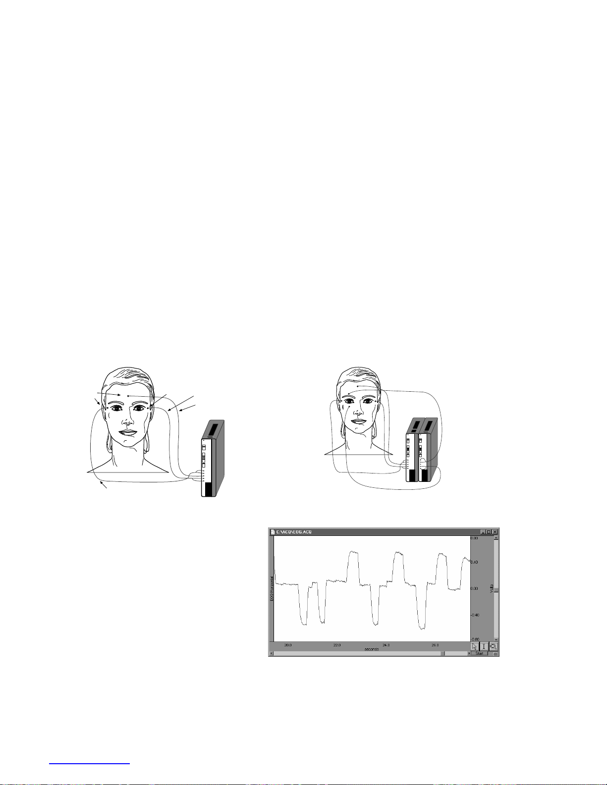
EOG100C – ELECTROOCULOGRAM AMPLIFIER MODULE
The electrooculogram amplifier module (EOG100C) is a single-channel, high-gain, differential input, biopotential
amplifier designed for tracking eye movement. The EOG100C is designed for use in the following applications:
Sleep studies Nystagmus testing Vertigo investigations
Eye motion and tracking REM activity analysis Vestibular function studies
The EOG100C senses the corneal-retinal potential inherent in the eyeball. As the eyes move in the horizontal and
vertical planes, these potentials are superimposed to generate a DC voltage variation in the region immediately
surrounding the eye sockets.
The EOG100C will connect directly to any of BIOPAC’s Ag-AgCl series lead electrodes. For most EOG
applications, EL503 electrodes are used. Use two shielded electrode leads (LEAD110S) for the signal inputs and
one unshielded electrode lead (LEAD110) for ground.
The EOG100C has built-in drive capability for use with shielded electrode leads. If high bandwidth (resolution)
EOG measurements are required, then shielded electrode leads are recommended. When the interference filter is
switched on, shielded leads are typically not necessary. The EOG100C is designed to pass the EOG signal to
accommodate a large velocity range with minimal distortion.
This module includes an HP selection switch, which permits either absolute (DC) or relative (AC: 0.05Hz HP) eye
motion measurements. When performing absolute eye motion measurement, the eye position signal will still decay,
but the time constant will be significantly longer than when performing relative eye motion measurement.
The EOG100C also has an EOG derivative function. When enabled, the output signal will produce a wave that will
be directly proportional to the velocity of eye movement. Eye velocity measurement is useful for performing
Nystagmus testing. The derivative function is obtained through the use of a specially designed bandpass filter
(center frequency of 30Hz, Q=0.8).
EL503
LEAD100S
EL503
LEAD100S
LEAD100
ZERO
ADJ
DERIV
NORM
ON
FILTER
OFF
AC
DC
SHIELD
VIN+
GND
VIN-
SHIELD
EOG100
GAIN
500
1000
2000
5000
Setup to record horizontal eye movement
To increase accuracy, use electrodes above and
below each eye and parallel them with
JUMP100C Jumper leads when connecting to
the vertical track EOG100C module.
This graph shows a horizontal eye movement
recording. The positive peaks indicate eyes
looking left. The negative peaks indicate eyes
looking right. The derivative of this waveform
would indicate the speed of eye motion during
this time.
ZERO
ZERO
ADJ
ADJ
GAIN
GAIN
500
500
1000
1000
2000
2000
5000
5000
DERIV
DERIV
NORM
NORM
ON
ON
FILTER
FILTER
OFF
OFF
AC
AC
DC
DC
SHIELD
SHIELD
VIN+
VIN+
GND
GND
VIN-
VIN-
SHIELD
SHIELD
EOG100
EOG100
Setup for two EOG100C modules to record
vertical and horizontal eye movement
Typical EOG signal
www.biopac.com 99
Page 100
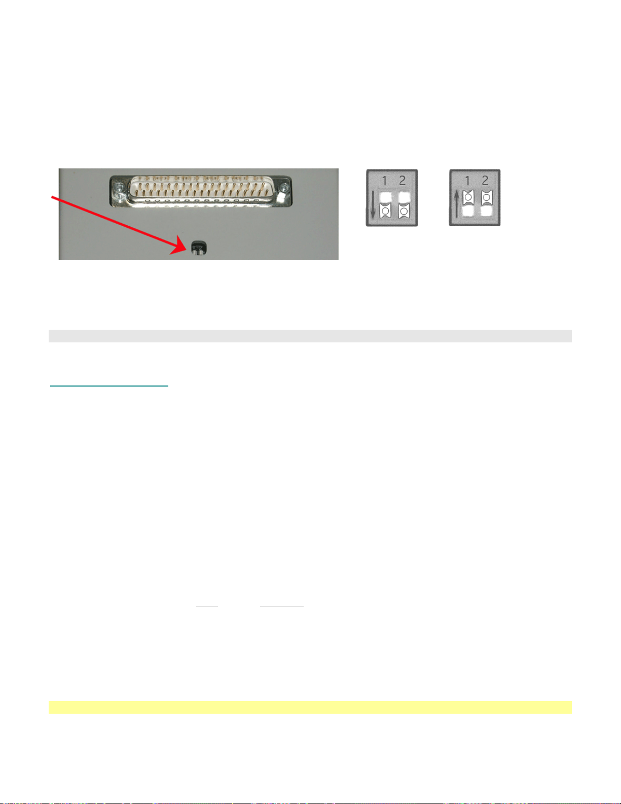
Frequency Response Characteristics
The 0.05Hz lower frequency response setting is a single pole roll-off filter.
Modules can be set for 50Hz or 60Hz notch options to match the wall-power line frequency of the destination
country. The proper setting reduces noise from interfering signals when the notch filter is engaged. Generally, wallpower line frequency is 60Hz in the United States and 50Hz in most of Europe; contact BIOPAC if you are unsure
of your country’s line frequency. To reset the line frequency setting, adjust the bank of switches on the back of the
amplifier module.
Line Frequency switch bank is on the back of the amplifier 50Hz 60Hz
See the sample frequency response plots beginning on page
241:
Both switches
DOWN
Both switches
UP
35Hz LPN (with 50Hz notch)
35Hz LPN (with 60Hz notch)
100Hz LP
EOG100C Calibration
The EOG100C is factory set and does not require calibration. To confirm the accuracy of the device, use the
CBLCALC.
EOG100C Specifications
Gain: 500, 1000, 2000, 5000
Output Selection: Normal, Derivative output
Output Range: ±10V (analog)
Frequenct Response
Low Pass Filter: 35Hz, 100Hz
High Pass Filter: DC, 0.05Hz
Notch Filter: 50dB rejection @ 50/60Hz
Noise Voltage: 0.1µV rms – (0.05-35Hz)
Signal Source: Electrodes (three electrode leads required)
Z (input)
Differential: 2MΩ
Common mode: 1000MΩ
CMRR: 110dB min (50/60Hz); see Shield Drive Operation on page
241
CMIV–referenced to
Amplifier ground: ±10V
Mains ground: ±1500 VDC
Input Voltage Range Gain
Vin (mV)
500 ±20
1000 ±10
2000 ±5
5000 ±2
Weight: 350 grams
Dimensions: 4cm (wide) x 11cm (deep) x 19cm (high)
See also: JUMP100C and MEC series
100 MP System Hardware Guide
 Loading...