


 Loading...
CROSSVENT-3
INTENSIVE CARE/TRANSPORT
VENTILATOR
OPERATION & SERVICE MANUAL
CATALOG #3304 revision: 122606
Bio-Med Devices, Inc.
61 Soundview Road, Guilford, CT 06437
800-224-6633 FAX 203-458-0440 Web Site: www.biomeddevices.com
COPYRIGHT 1997 BIO-MED DEVICES INC.
TABLE OF CONTENTS |
|
QUICK REFERENCE ................................................................................................................... |
1 |
ADDENDUM 1............................................................................................................................... |
2 |
ADDENDUM 2............................................................................................................................... |
2 |
I. PATIENT SAFETY, WARNINGS, AND CAUTIONS ............................................................ |
5 |
WARNINGS............................................................................................................................... |
5 |
CAUTIONS................................................................................................................................ |
9 |
NOTES...................................................................................................................................... |
10 |
SYMBOLS................................................................................................................................ |
12 |
II. GENERAL DESCRIPTION ................................................................................................... |
13 |
A- INTRODUCTION.............................................................................................................. |
13 |
III. USER INTERFACE, CONNECTIONS AND SPECIFICATIONS................................... |
15 |
A- CONTROLS AND MENU DISPLAYS............................................................................ |
17 |
B- INFORMATIONAL DISPLAYS AND INDICATORS.................................................. |
22 |
C- CONNECTORS & MISC.................................................................................................. |
24 |
D- ADDITIONAL SPECIFICATIONS................................................................................. |
28 |
IV. ASSEMBLY AND INSTALLATION .................................................................................... |
29 |
A- EQUIPMENT AND ACCESSORIES .............................................................................. |
29 |
B- INSTALLATION ............................................................................................................... |
30 |
C. PATIENT CIRCUIT CONNECTIONS ........................................................................... |
31 |
V. TESTS, CALIBRATION AND TROUBLESHOOTING ....................................................... |
32 |
A- TEST MENU (SELF-DIAGNOSTICS) ........................................................................... |
32 |
B- CALIBRATION MENU .................................................................................................... |
33 |
C- OPERATIONAL TROUBLESHOOTING...................................................................... |
34 |
VI. OPERATING INSTRUCTIONS ........................................................................................... |
36 |
A- PRELIMINARY STEPS.................................................................................................... |
36 |
B- DETAILED OPERATING INSTRUCTIONS................................................................. |
36 |
C- SUMMARY OF OPERATING INSTRUCTIONS ......................................................... |
38 |
VII. CLEANING, STERILIZATION AND PACKING ............................................................. |
39 |
A- CLEANING AND STERILIZATION.............................................................................. |
39 |
B- PACKING FOR SHIPMENT ........................................................................................... |
40 |
VIII. THEORY OF OPERATIONS............................................................................................. |
42 |
A- SYSTEM COMPONENTS................................................................................................ |
45 |
B- ASSIST CONTROL MODE.............................................................................................. |
46 |
C- SIMV (Synchronized Intermittent Mandatory Ventilation) MODE ............................ |
47 |
D- CPAP (Continuous Positive Airway Pressure)................................................................ |
48 |
E- BACKUP MODALITY...................................................................................................... |
49 |
IX. MAINTENANCE AND SERVICE ....................................................................................... |
50 |
A- TEST & CALIBRATION MENU OVERVIEW............................................................. |
50 |
B- PERFORMANCE CHECKS............................................................................................. |
53 |
C- RECOMMENDED TOOLS AND TEST EQUIPMENT ............................................... |
58 |
D- PREVENTATIVE MAINTENANCE .............................................................................. |
59 |
E- PNEUMATIC CALIBRATION........................................................................................ |
62 |
F- TECHNICAL TROUBLESHOOTING CHART ............................................................ |
71 |
G- DISASSEMBLY & REASSEMBLY INSTRUCTIONS................................................. |
74 |
X. PARTS LIST AND SCHEMATIC DIAGRAMS .................................................................. |
77 |
A- REPLACEMENT PARTS LIST..................................................................................... |
77 |
B- SCHEMATICS .................................................................................................................. |
79 |
WARRANTY ................................................................................................................................. |
88 |
APPENDIX A ............................................................................................................................... |
89 |
ABBREVIATIONS.................................................................................................................. |
89 |
APPENDIX B ............................................................................................................................... |
90 |
DEFAULT SETTINGS........................................................................................................... |
90 |
APPENDIX C ............................................................................................................................... |
91 |
SUMMARY OF PARAMETER RANGES / ACCURACIES............................................. |
91 |
APPENDIX D............................................................................................................................... |
92 |
SUMMARY OF DISABLED FUNCTIONS ......................................................................... |
92 |
APPENDIX E ............................................................................................................................... |
93 |
FAIL-TO-CYCLE ALARMS................................................................................................. |
93 |
APPENDIX F ............................................................................................................................... |
94 |
EUROPEAN AGENT ............................................................................................................. |
94 |
INDEX .............................................................................................. |
Error! Bookmark not defined. |

QUICK REFERENCE
1

ADDENDUM 1
AIR ENTRAINMENT
When equipped with the Air Entrainment Module, the CV-3 is able to supply either 100% or 50% (nominal) oxygen during transport, without the use of compressed air. A unique feature of the entrainment system is the ability to deliver repeatable volumes during volume limited ventilation, with relatively constant oxygen concentration.
When the air entrainment control on the right side of the CV-3 is turned to the ON position, a sophisticated, multiple venturi system is activated, which draws in ambient air and dilutes the 100% O2 supply gas to a nominal 50% concentration.
An additional advantage of using entrainment is that the oxygen supply consumption will be reduced, thereby increasing the operating time on a given supply of gas.
WARNING: Operation of the Crossvent in a contaminated environment can be hazardous when entrainment is used.
NOTE: With entrainment on, flow accuracy from 5 - 100 LPM is ±10% or 1
LPM, whichever is greater, and with a flow of 100 LPM and over, flow accuracy is within 15% of displayed flow. No accuracy is claimed below 5 LPM.
When air entrainment is on, verify the message “ENTRN” is displayed in the entrainment on window to the left of O2 Quiet.
Set the FLOW after entrainment is turned on since the flow calibration is automatically adjusted for entrainment.
It is not recommended that entrainment be turned on or off while ventilating.
However, if this should become necessary, then it should be done during the expiratory phase of the breathing cycle.
ADDENDUM 2
CHARGERS AND INVERTERS
This addendum explains some of the requirements for connecting a Bio-Med Devices Crossvent ventilator to a charger or AC adapter. It is important that the correct charger be used and if a Crossvent is to be used in a vehicle with an AC generating device (inverter), it must comply with certain requirements.
1. LAND OPERATION
When using an AC adaptor to either run the Crossvent or to charge the batteries, only the Jerome Industries model WSZ116M (16VDC 3A) charger supplied by Bio-Med Devices should be used.
The Bio-Med charger has been thoroughly tested for proper operation with the Crossvent to make sure that all standards are met. This includes all of the applicable
2
standards for safety, EMI/RFI, power surges, and leakage. It is approved for medical applications and conforms to FDA, CE, UL, and other required standards.
Although other forms and brands of chargers may operate the Crossvent, there is no guarantee of system reliability or conformance to required standards.
Should an emergency arise and it becomes necessary to operate the Crossvent without the Bio-Med charger, use only a charger that is approved for medical use and complies with all applicable standards. It must produce filtered DC voltage ranging between 12 and 28 volts DC and be rated for continuous 2.5 amps of current.
WARNING: Although the Crossvent will operate with an external power source from 12 – 28 VDC, when at 12 volts the battery will not charge.
Should a Crossvent fail to operate or charge from a charger, both the Crossvent and the charger should be returned together to Bio-Med Devices for evaluation.
2. AIR OPERATION – FIXED OR ROTARY WING AIRCRAFT
The aircraft industry is constantly making technical advancements in the areas of composite material construction and weight reduction of installed equipment.
Unfortunately, this can conflict with the safe operation of some electronic medical equipment. Composite materials do not work well as a grounding agent for electronic equipment. The weight reduction techniques used in AC inverters often create unsafe conditions when operating electronic medical equipment.
The Crossvent is designed to operate from an external power source delivering 12 to 28 volts DC at a continuous current of 2.5 amps.
WARNING: Although the Crossvent will operate with an external power source from 12 – 28 VDC, when at 12 volts the battery will not charge.
It is best to operate the Crossvent from the aircraft’s 24-volt DC battery source, rather than an AC inverter. To insure the best “grounding” between the Crossvent and the aircraft metal frame, connect the Crossvent directly to the 24-volt DC power bus through appropriate fusing. This will keep extraneous interference and current leakage to a minimum.
3. INVERTER OPERATION
If it is necessary to operate the Crossvent from an AC inverter, similar to KGS Electronics brands, only those inverters in compliance with NEMA standards should be used. Inverters with “split winding” output transformers should not be used with the
Crossvent and supplied charger.
The inverter output must be configured like standard household or industrial wiring, where the black wire is “hot”, the white wire is “neutral”, and the green wire is “ground”.
The neutral and ground wires should be connected together at one point of the frame so that there is no voltage between them, and there should be 115 volts AC between the hot and neutral wires.
The inverter receptacles must be of the standard three-prong configuration to utilize the hospital-grade cord of the Bio-Med supplied charger. This will keep voltage surges,
3
spurious noise and leakages to a minimum.
Any other type of AC/DC power supply or charger, such as open frame devices, medically approved or not, is not recommended by Bio-Med Devices.
4
I. PATIENT SAFETY, WARNINGS, AND CAUTIONS
The CROSSVENT-3 ventilator is intended for use only by a qualified practitioner, under the direction of a qualified physician. All personnel operating the ventilator must be completely familiar with the warnings and operating procedures in this manual prior to using the CROSSVENT-3 with patients. As with any life support device, the patients on the CROSSVENT-3 should be visually monitored by competent personnel at all times since life threatening conditions may arise that may not be detected by the alarms. It is essential to test all life-support devices for proper function prior to each use on patients.
A- WARNINGS, CAUTIONS, AND NOTES
The following terms are used throughout this manual:
WARNING - Indicates a procedure or condition that could cause bodily injury.
CAUTION - Signifies a procedure or condition that could damage the equipment.
NOTE - Refers to a procedure or condition that requires special attention.
WARNINGS
•Whenever the CROSSVENT-3 is connected to a patient, a skilled operator should always be present at all times at the ventilator or within hearing range of the ventilator’s alarm system.
•If the battery has not been periodically refreshed, the amount of time the Crossvent will operate on battery power may be substantially reduced even though it indicates a full charge.
•High oxygen concentrations may be hazardous to the patient.
•If the gas supply fails or there is a total electrical power failure, the patient may breath atmospheric gas through the failsafe valve. This is, however, only a temporary emergency measure, which requires elevated inspiratory effort and it should be corrected immediately.
•In the aforementioned case, or in the case of entrainment usage, the operation of the Crossvent in a contaminated environment can be hazardous.
•Always operate the CV-3 on battery prior to use to confirm that the battery is functioning.
•In the event of an AC power failure, the CROSSVENT-3 will automatically switch over to battery operation and sound an alarm. The audible alarm may be silenced by pressing the POWER SOURCE window. On a fully charged battery, there will be a minimum of 11 hours of autonomous operation (assuming a 10% on-time of the LCD back light). No further alarm will be sounded until the battery is low. The low battery alarm may then also be permanently silenced by pressing the POWER SOURCE window. It is imperative to restore AC power at this time to assure continued safe operation of the ventilator.
5
I.PATIENT SAFETYcont.
•A patient filter should always be used in the patient breathing circuit to prevent cross contamination.
•Extreme care should be taken to assure that the patient circuit components are connected correctly. Improper connection can cause malfunction.
•Periodically the CROSSVENT-3 should be operated in the test mode to ascertain that it is functioning properly. A test lung should be ventilated prior to each use to further insure that all modes are functioning correctly. An external spirometer should be used to verify correct volumes and flow rates.
•The patient should never be left unattended after the ALARM QUIET key is depressed since this is followed by a period when the audible alarms are deactivated.
•An audible alarm always indicates an anomalous state which should always be rectified.
•While the oxygen sensor alarm may be turned off to permit use of the CROSSVENT-3 without this sensor, it is recommended that it be used at all times.
•Always be certain that the Maximum Pressure Limit is set correctly and is operative even when volume limiting, to prevent possible inadvertent administration of high pressure. Increased pressure can be caused by blocked tubes, changes in patient compliance or resistance, or system malfunction.
•Under certain conditions in SIMV with PEEP, when the low peak pressure alarm is set correctly for assisted breaths, there may be no low peak pressure alarm following a patient disconnect until the next assisted breath. This period may be up to 2 minutes.
•The alarm ports on the front of the CV-3 should never be obstructed.
•For proper operation only the O2 sensor supplied by Bio-Med Devices may be used.
•Never operate the CROSSVENT-3 without a battery since it will fail to operate if the plug-in power supply is removed.
•The screened ports on the side, back, and bottom of the unit should not be obstructed when the ventilator is in use.
•Only qualified, trained, service technicians should attempt repairs and service when needed. Serious personal injury and/or equipment damage can result if repairs are performed by unqualified personnel
•The default pressure calibration may not be as accurate as the normal calibration procedure. The normal calibration procedure should be performed instead whenever possible.
• It is imperative to verify that clinically appropriate alarm limits are fully
6
I.PATIENT SAFETYcont.
operational following connection of the ventilator to a patient.
•It is important to note that once a sensor has been turned off, the alarms for that sensor are inoperative.
•When using the Crossvent with an air/oxygen blender, there may be a reduction in the delivered flow at the higher flow settings. This reduction may occur when
the blender is set below 30% or above 90% O2 and the Crossvent is set to flows above 80 lpm. Lower supply pressures to the blender will tend to decrease the flow further so be sure these supply pressures are maintained at 4575 PSI (310-517 kPa). An external spirometer is recommended to verify the flow.
•Breathing through the negative pressure relief valve requires a greatly increased work of breathing and only air is provided. A situation in which the patient is breathing through this valve should be rectified immediately in order to prevent possible adverse affects to the patient.
•It is extremely important that the Sensitivity control be carefully adjusted to assure proper operation in the CPAP mode.
•It is important in Backup modality to always set a correct rate, tidal volume and flow to insure proper ventilation in case the patient becomes apneic.
•The default calibration may not be as accurate as the normal calibration procedure. The normal calibration procedure should be performed instead whenever possible.
•To obtain the full 3-minute duration of the fail-to-cycle alarm, the Crossvent must have been powered on for at least 5 minutes.
•All safety measures must be observed when servicing this device. In particular, the ventilator must be turned off and the power supply disconnected.
•Bio-Med Devices cannot be held responsible for any failure to adhere to the recommendations set forth in this manual.
•Because this is a CE marked device, it must never be modified without prior expressed written consent from Bio-Med Devices.
•When setting Sensitivity, auto-triggering or missed breaths may occur due to various conditions including, but not limited to, compliance, resistance, rate, flow, PEEP, I:E ratio, and circuit characteristics.
•Do not re-use disposable breathing circuits.
•Operation of the Crossvent in a contaminated environment can be hazardous when entrainment is used.
•If the battery has not been periodically refreshed, the amount of time the Crossvent will operate on battery power may be substantially reduced even though it indicates a full charge (see Section III, Part C-3).
7
I.PATIENT SAFETYcont.
•Although the Crossvent will operate with an external power source from 12 – 28 VDC, when at 12 volts the battery will not charge.
8
I.PATIENT SAFETYcont.
CAUTIONS
•Clean, dry, medical grade gas sources supplied at 44 to 66 psi (303.6 – 455.4 kPa) unrestricted flow must be used at all times to assure proper operation of the CROSSVENT-3 Ventilator.
•The CROSSVENT-3 should not be steam or gas sterilized as this will result in damage to some of its components.
•Connect the oxygen sensor (optional) upstream of the humidifier since the fuel cell functions better in non-humidified gas.
•Touch screen control keys should be pressed by hand only. Care should be taken not to allow keys to be contacted by sharp objects as damage may result.
•Clean touch screen only with alcohol. Clean the rest of the CROSSVENT-3 unit with mild, non-abrasive, anti-bacterial cleanser.
•Do not place liquids on or near the CROSSVENT-3. Liquid entering the unit can cause severe damage and malfunction.
•It is recommended that the CROSSVENT-3 never be left with its battery discharged as this will reduce battery life. After discharge of the battery, recharge fully before disconnecting the plug-in power supply. For maximum battery life, periodically discharge the battery fully and then recharge.
•Only replace the battery pack with Bio-Med Devices part #PRT4402. Do not substitute. The cells are non-standard high capacity.
•When using an AC power source, only the power supply provided with the Crossvent is approved for use with this ventilator. Any other power supply may cause damage and/or unreliable operation (see Addendum 2).
•Any more comprehensive DC power supply than that which is supplied must be short circuit protected and must comply with all of the specifications and standards as listed in Section III, Part D.
•Do not use in a MRI room.
•Antistatic or electrically conductive hoses or tubing should not be used.
•When it is necessary to operate the Crossvent from an AC inverter, only inverters in compliance with NEMA standards should be used (see Addendum 2).
•The Flow Valve (11) is geared to the Potentiometer (20) and it is the Potentiometer limits that stops the valve. Do not force.
9

I.PATIENT SAFETYcont.
NOTES
•With entrainment on, flow accuracy from 5 - 100 lpm is ±10% or 1 lpm, whichever is greater, and with a flow of 100 lpm and over, flow accuracy is within 15% of displayed flow. No accuracy is claimed below 5 lpm.
•Battery Backed MemoryWhen the CROSSVENT-3 is turned on, it automatically recalls all of the settings stored in memory before it was turned off. This memory is protected by its own separate internal battery which should last for over 7 years (ref. Section IX, Preventative Maintenance). The parameters stored are: all the main functions; high and low alarm limits; secondary modes; oxygen and flow calibrations; and which sensors are on or off. Several factors can cause the battery backed memory to be lost. These are: low battery backed memory battery voltage (service required); defective random access memory (service required); or if the microprocessor is, by chance, storing data in the battery backed memory at the time power is turned off. In this case it is necessary to re-enter the previously set parameters.
•The Maximum Pressure should always be set higher than PEEP in order to achieve the PEEP setting.
•To conserve gas, the Maximum Pressure and PEEP controls should be turned off (fully counter clockwise) when the CV-3 is not in use.
•The fail-to-cycle alarm may not be silenced using the Alarm Quiet key. The fail- to-cycle alarm may be silenced by pressing the alarm reset button or by pressing a mode key.
•Battery power is substantially reduced if the backlight is on continuously. To conserve battery power, turn the backlight off when it is not needed.
•Sensitivity is disabled at respiratory rates above 60 bpm.
•Pressure Support is only active during SIMV and CPAP, but may be set at any time.
•The wall plug-in power supply is furnished for 117 VAC, 60 Hz or 220 VAC, 50 Hz operation, as required. It is not possible to overcharge the battery. In order to maximize battery life, periodically discharge the battery fully and then recharge. Additionally, always keep the battery fully charged when not in use.
•In the Pressure calibration menu, after pressing the default key, it is important to then perform the zero pressure calibration as outlined in the instructions.
Warning: the default calibration may not be as accurate as the normal calibration procedure. The normal calibration procedure should be performed instead whenever possible.
•It is important to use the correct reference gases (100 and 21%) when performing the Oxygen sensor calibration. A worn out sensor will not calibrate accurately.
•Since it is not possible to damage the CROSSVENT-3 ventilator by normal use
10
I.PATIENT SAFETYcont.
of its keys and control knobs, the user is encouraged to experiment with the
CROSSVENT-3 settings while the unit is not connected to a patient.
•Reverse field on the display indicates that a parameter has been selected and may be adjusted using the arrow keys.
•If it is desired to deactivate the oxygen sensor, select it and scroll the lower limit down to off. The oxygen function is now inoperative. The function may be reactivated at any time by pressing it and scrolling the low limit up. The oxygen sensor is now reactivated. This allows the ventilator to be used without the oxygen sensor. When this sensor is off, it may be disconnected while the ventilator is in use, without causing an alarm.
•For blended gas, the Bio-Med Devices blender should be used.
•It is recommended that an external filter/water trap be used at all times in order to provide greater protection to the internal components of the CROSSVENT-3.
•For greatest accuracy, verify flow using a 60% O2 gas supply, making certain that the pressure to the CV-3 inlet remains within specified pressure limits
(44-66 psi; 303.6 –455.4 kPa) at all flows.
•If a period longer then 60 sec passes before pushing BATTERY block when the Crossvent is first turned on, an audible alarm will sound. When BATTERY block is pushed, the audible alarm will also be silenced.
•Due to the fact that O2 sensors sometimes change output over time once exposed to atmosphere, a calibration should be performed periodically (once a month) in order to assure optimal accuracy. When the sensor is consumed and does not calibrate properly, it should be discarded and a new sensor installed and calibrated.
•It is not recommended that entrainment be turned on or off while ventilating. However, if this should become necessary, then it should be done during the expiratory phase of the breathing cycle.
•20 minutes of operation after low battery alarm assumes a properly maintained battery in good condition.
•The battery should be replaced at least every two years. Only use batteries supplied by Bio-Med Devices, part #PRT4402.
•To conserve gas, the Maximum Pressure and PEEP controls should be turned off (fully counter clockwise) when the CV-3 is not in use.
•Prior to disposal of any component, with particular attention to the battery and PCB, check with your local controlling authority for disposal regulations.
•In this manual, when references are made to keys, this is area of the display containing text or values. There may not always be a “key” depicted graphically. When instructed to press a key, it is implied to press on the display on top of the word or value.
11

I.PATIENT SAFETYcont.
SYMBOLS
Type BF Equipment
Date of Manufacture
Direct Current (DC)
Connector Polarity
Must be disposed of in accordance with WEEE Directive.
At the unit’s “end of life”, it may be returned to the manufacturer for proper reclamation.
It is essential that these instructions be read and complied with prior to operating this product.
On
Off
12
II. GENERAL DESCRIPTION
A- INTRODUCTION
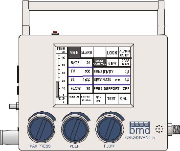
Fig. 1 - CV-3 FRONT PANEL
The CROSSVENT-3 Intensive Care/Transport Ventilator is an ultra compact, electronically controlled, time cycled, volume or pressure limited ventilator with intensive care capabilities. It provides a wide range of operating parameters to allow ventilatory support of patients from pediatric through adult. The CROSSVENT-3 delivers the same oxygen concentration as the supply gas.
The ventilator’s microprocessor provides all operational functions, as well as monitoring the patient and providing alarms. It allows the user to enter many different operational and alarm parameters to accommodate a wide variety of clinical situations.
Airway pressure is sensed using an internal solid-state pressure transducer, and pressure is displayed as a bar graph on the LCD. The patient inspiratory effort is also sensed using a solid-state pressure transducer. An absolute pressure transducer monitors atmospheric pressure and automatically compensates for altitude changes.
Since the CROSSVENT-3 is totally separable from a compressor and since it may be used with any 55 ±20% psi (379 ±20%kPa) gas source, it is extremely versatile. It may be used in most areas of the hospital and in transport. It may be mounted on a compressor, on a pedestal stand, a cart, a wall bracket, or a bed rail. It may also be mounted in vehicles such as helicopters and ambulances.
CAUTION: Do not use in a MRI room.
13
II.GENERAL DESCRIPTIONcont.
The CROSSVENT-3 has an internal battery which provides power during transport and in the event of an AC power failure. If the external power should fail, the ventilator automatically switches to its internal battery and sounds an alarm. The ventilator will function on a fully charged battery for a minimum of 11 hours. Whenever external power is restored, the CROSSVENT-3 switches back to external power operation. It will charge the battery from its internal charging circuit whenever external power is available.
The CROSSVENT-3 Ventilator’s extreme reliability is made possible by: 1- A minimum of rotating or sliding mechanical parts.
2- An absolute minimum of moving parts.
3- An extremely low total parts count.
In addition to increased patient safety, the high reliability insures low downtime and thus more economical use.
The CROSSVENT-3 provides a complete array of features and ventilatory modes and functions which include:
Microprocessor control of all operational functions and monitoring.
A Graphic LCD (liquid crystal display) with a touch screen keypad superimposed, allowing the clinician to select functions just by pressing the function displayed by the LCD. This provides the friendliest and most flexible possible user interface.
Automatic switch-over to battery backup operation. Auto-test mode with complete microprocessor diagnostics.
Sensors to measure airway pressure, oxygen concentration (optional).
Displays and alarms for Peak Pressure, Rate, and Oxygen concentration. Programmability and expandability.
Built-in triggered demand flow for minimum work of breathing during SIMV and CPAP and a simplified system design.
Integral ASSIST CONTROL, SIMV, CPAP, PEEP, and Pressure Support functions.
Backup breath modality in SIMV or CPAP.
RS-232 input for PC interface for software updates.
14
III. USER INTERFACE, CONNECTIONS AND
SPECIFICATIONS
Careful attention has been paid to the human interface of the CROSSVENT-3. Its Graphic LCD, with touch screen keypad, makes it the most user friendly ventilator for today and tomorrow. Two menus are available on the LCD. These are Main and Alarm.
Each menu is divided into several sections: a- Airway Pressure bar graph.
b- Menu line.
c- Permanent Function Keys: RATE; TIDAL VOLUME; UP and DOWN
Arrows; ALARM QUIET; MANUAL; LOCK.
d- Displays and Indicators: Flow; I/E Ratio; insp. source; power source; sigh breath.
e- Selectable functions area.
A menu is selected simply by pressing either the Main or the Alarm key in the menu line.
NOTE: In this manual, when references are made to keys, this is area of the display containing text or values. There may not always be a “key” depicted graphically. When instructed to press a key, it is implied to press on the display on top of the word or value.
Procedure for selecting a function and adjusting its setting:
A function is selected by touching the window (key) labeled with the function name. . This is best done with the tip of the finger or even the fingernail. When a function is selected, the function will be shown in “reverse video”. This means that the normal dark print on light background will switch temporarily to light print on a dark background.
Once a parameter is selected it may be adjusted using the UP and DOWN Arrow keys. The parameter key may be pressed again to turn it off, i.e., deactivate the function. If the parameter or the arrow keys are not pressed for 30 sec., the parameter key will automatically deactivate parameters. The following are exceptions to the procedure for setting functions:
Modes are selected simply by pressing the desired mode key.
Flow is displayed in the Flow window, but may be changed only with the FLOW
Control Knob.
I/E ratio is a display window only. I/E is set indirectly by setting Rate, Tidal Volume and Flow.
NOTE: BATTERY BACKED MEMORY. When the CROSSVENT-3 is turned on, it automatically recalls all of the settings stored in memory before it was turned off. This memory is protected by its own separate internal battery which should last for over 7 years (ref. Section IX, Preventative Maintenance). The parameters stored are: all the main functions; High and Low alarm limits; secondary modes; oxygen and flow calibrations; and which sensors are on or off.
15
III.USER INTERFACE, CONNECTIONS AND SPECIFICATIONS- cont.
Several factors can cause the batterybacked memory to be lost.
These are: low Battery Backed Memory battery voltage (service required); defective random access memory (service required); or if the microprocessor is, by chance, storing data in the battery backed memory at the time power is turned off. In this case it is necessary to re-enter the previously set parameters.
16
III.USER INTERFACE, CONNECTIONS AND SPECIFICATIONS- cont.
A- CONTROLS AND MENU DISPLAYS 1- MANUAL CONTROLS
FLOW CONTROL- A pneumatic needle valve which sets the inspiratory flow from 0- 120 lpm (see fig. 1). Its shaft is encoded by connecting it to a precision, multiturn potentiometer. The Flow window displays the flow setting. It is accurate from 1 to 120 lpm.
WARNING: When using the Crossvent with an air/oxygen blender, there may be a reduction in the delivered flow at the higher flow settings. This reduction may occur when the blender is set below 30% or above 90% O2 and the Crossvent is set to flows above 80 lpm. Lower supply pressures to the blender will tend to decrease the flow further so be sure these supply pressures are maintained at 4575 PSI (310-517 kPa). An external spirometer is recommended to verify the flow.
MAXIMUM PRESSURE- A pneumatic needle valve which sets the pressure which is applied to the exhalation valve and to the internal diaphragm actuated relief valve (D.A.R.V.) and determines the maximum pressure during assisted and controlled inspirations. It is adjustable from 0 - 120 cmH2O. It should always be operative and properly adjusted. 
NOTE: To conserve gas, the Maximum Pressure and PEEP controls should be turned off (fully counter clockwise) when the
CV-3 is not in use.
PEEP (Positive End Expiratory Pressure)- A |
|
|
|
|
pneumatic needle valve which sets the PEEP or |
|
|
|
|
CPAP (Continuous Positive Airway Pressure) level |
|
|
POWER |
|
which is applied to the exhalation valve. |
It is |
|
|
|
|
|
ON |
||
adjustable from 0- 35 cmH2O. The PEEP level is |
|
|
||
|
|
OFF |
||
determined by observing the system pressure bar |
|
|
||
|
|
|
||
graph. |
|
|
|
|
NOTE: The Maximum Pressure should |
|
|
! |
|
always be set higher than PEEP in order to |
|
|
RS232 |
|
achieve the PEEP setting. |
|
EXH |
AIRWAY |
O2 |
NOTE: To conserve gas, the Maximum |
VALVE |
PRESSURE |
||
|
|
|
||
Pressure and PEEP controls should be |
PATIENT |
|
||
|
|
|
||
turned off (fully counter clockwise) |
when |
|
|
ALARM |
|
|
RESET |
||
the CV-3 is not in use. |
|
|
|
|
|
|
|
|
|
POWER ON/OFF- It is located on the left side of the unit (see fig. 2) and is recessed in order to
reduce inadvertent or unauthorized use. It controls the main power to the electronics. If the battery is allowed to fall below 6 volts (well below the Low Battery alarm limit) with the unit operating, the ventilator will turn off independent of this switch. If this occurs, this switch must be turned to Off before the ventilator will operate again, regardless of power source.
WARNING: Never use the on/off switch to silence the alarms since this renders the alarms permanently disabled.
ALARM RESET SWITCH (see fig. 2) - Silences the alarm of the Power
17
III.USER INTERFACE, CONNECTIONS AND SPECIFICATIONS- cont.
Failure/Fail-to-Cycle circuit, which is a separate section of the main circuit board.
It is not under the control of the microprocessor.
WARNING: To obtain the full 3-minute duration of the fail-to-cycle alarm, the Crossvent must have been powered on for at least 5 minutes.
This fail-safe circuit has 3 functions:
1- Monitors the power to the main circuit board. If power is lost, either as a result of turning the main power switch off or a total power failure to the circuit board, i.e., no external power and no battery, it sounds an audible alarm (long tone) and flashes the LED which will continue for at least 3 min. after failure. This may be less if the unit has been on for less than 5 minutes. The audible alarm is permanently silenced by pressing the Alarm reset switch.
2- Monitors the signals to the A and B solenoid valves. If it does not sense a change in state of the control signal to the appropriate valve, depending on the mode, once every 40 sec. (or every 2 min. for valve B when in the SIMV mode), it sounds an audible alarm (one long, one short tone for Solenoid A; one long, two short tones for Solenoid B) and flashes the LED. When the fail-to-cycle condition is corrected, the alarm is canceled. Additionally, pushing the ALARM RESET switch locks out the audible alarm for 60 sec. Turning the unit off and pressing the switch also permanently silences the alarm.
3- Monitors the microprocessor. If communication between the fail-to–cycle and the microprocessor is lost, it sounds an audible alarm (one long, three short tones) and flashes the LED. The audible alarm may be silenced by pressing the ALARM
RESET switch.
2- KEYS COMMON TO ALL MENUS
RATE- Sets the normal respiration rate. It is adjustable from 5 to 150 bpm. When in SIMV or CPAP, this changes to BACKUP RATE and is used to set the backup rate.
TIDAL VOLUME- Sets the volume of gas delivered during assisted or controlled inspirations. It is adjustable from 5 to 2500 ml. It is accurate from 50 to 2500 ml.
UP and DOWN Arrows- Scroll up and down, at an accelerating rate, any parameter selected and shown in reverse field (with the exception of flow, which may be changed only with the Flow control knob). At the end limits the display remains constant and a tone sounds.
ALARM QUIET- Silences the audible alarm for a period of 60 sec. or 120 sec. if pressed twice consecutively. When set, the key is shown in reverse video and counts down from the setting to show its status. If pressed a third time it reactivates the alarm. When the CV-3 is turned on, the Alarm Quiet is activated automatically for 60 sec.
NOTE: The Fail-to-Cycle alarm may not be silenced using this key. The Fail- to-Cycle alarm may be silenced by pressing the ALARM RESET button or by pressing a mode key.
LOCK- Locks all other keys, except BACK LIGHT, CONTRAST, ALARM QUIET and MENU keys, until it is pressed again twice within 5 sec. When locked, the key is shown in reverse video.
18

III.USER INTERFACE, CONNECTIONS AND SPECIFICATIONS- cont.
SIGH- Together with the ARROW keys, turns sigh on and off. When sigh is on, the tidal volume delivered is equal to 1.5 times the normal tidal volume, up to a maximum of 2500 ml. Sigh is operative only in the Assist Control and SIMV modes. One sigh breath is provided for every 100 normal breaths or one every 7 minutes, whichever occurs first. The CROSSVENT-3 delivers a sigh breath by increasing the inspiratory time of a normal breath. The expiratory time following a sigh is also increased to maintain the same I/E ratio as a normal breath. Each time a sigh breath is delivered, “SIGH BREATH” is displayed in this key.
BACKLIGHT- When the Crossvent is being used on external power, the LCD backlight is on continuously and cannot be turned off. When operating on battery if no key is pressed for a period of 30 sec., the backlight is automatically turned off. If the backlight is desired to be on continuously while in battery mode, then press and hold the pressure bar graph for 3 seconds until it beeps a second time. If the backlight is already on when this is done, it will now be off. Press the bar again to turn it back on. It will remain on until the bar is pressed again or the unit is turned off. Either of these conditions will restore the 30-second timeout.
NOTE: Battery power is substantially reduced if the backlight is on continuously. To conserve battery power, turn the backlight off when it is not needed.
LCD CONTRAST- May be increased by pressing the PEEP key in the lower left corner and decreased by pressing the PEAK key in the upper left corner of the display.
3- MAIN MENU (MAIN)
The Assist Control, SIMV and CPAP modes may be selected by pressing the corresponding mode key. The selected mode will be shown in reverse field and becomes immediately operative. The modes are:
ASSIST |
CONTROL |
mode |
- |
PEAK |
|
|
LOCK ALARMQUIET |
||||
Provides controlled or assist/control |
38 |
MAIN |
|
||||||||
ventilation |
depending |
upon |
the |
100 |
|
|
ASSIST |
|
CPAP |
||
|
RATE |
20 |
|
||||||||
Sensitivity setting. If the patient fails |
|
|
|||||||||
80 |
CONTROL SIMV |
MAN |
|||||||||
to |
initiate |
an |
inspiration, |
the |
60 |
TV |
500 |
SENSITIVITY |
|
0.8 |
|
CROSSVENT-3 will continue to |
|
||||||||||
|
|
|
|
|
|||||||
cycle at the respiratory rate set with |
40 |
I/E |
1:2.0 |
SIMV RATE |
BPM |
4.0 |
|||||
the RATE control. |
|
|
|
20 |
FLOW |
30 |
PRES SUPPORT |
OFF |
|||
|
|
|
|
|
|
||||||
SIMV (Synchronized Intermittent |
|
|
0 |
|
|
|
|
|
||
|
|
CONTROL |
EXTERNL |
SIGH |
TEST |
CAL |
||||
|
||||||||||
Mandatory |
Ventilation) |
mode - |
PEEP |
|
POWER |
OFF |
||||
Provides |
spontaneous |
and |
6 |
|
|
|
|
|
||
|
|
|
Fig. 3 - MAIN MENU |
|
|
|||||
intermittent |
assisted breaths. The |
|
|
|
|
|
||||
|
|
|
|
|
|
|
|
|||
patient is free to initiate spontaneous breaths at a flow rate set with the FLOW control and for the length of time of a normal inspiration as set with the TIDAL
VOLUME and FLOW controls. During these spontaneous breaths, a bolus of gas flows to the patient at PEEP or atmospheric pressure. The patient inspires the amount desired and the rest is dumped to atmosphere. At intervals set with the SIMV RATE control, a triggered breath is provided under pressure (synchronized mandatory breath).
19
III.USER INTERFACE, CONNECTIONS AND SPECIFICATIONS- cont.
CPAP (Continuous Positive Airway Pressure)/Manual mode - Provides spontaneous breaths at PEEP or atmospheric pressure (see spontaneous breaths under SIMV above). The manual key is operative in this mode.
MANUAL (MAN)- Operative only in the CPAP mode. Provides one normal controlled breath each time it is depressed, with inspiratory time and tidal volume as established by the Rate, Tidal Volume and Flow controls. Minimum expiratory time of 0.2 sec is provided.
SENSITIVITY- Sets the trigger level below baseline (PEEP or atmospheric) at which an inspiration is initiated. It automatically adjusts for the PEEP level. It is functional in all modes and must be set for use during assisted and spontaneous breaths. It may be set to sense negative pressure changes from 10 cmH2O to less than 1 cmH2O below baseline. It should be adjusted for changes in the flow setting.
WARNING: When setting Sensitivity, auto-triggering or missed breaths may occur due to various conditions including, but not limited to, compliance, resistance, rate, flow, peep, I:E ratio, and circuit characteristics.
NOTE: Sensitivity is disabled at respiratory rates above 60 bpm.
SIMV RATE- Determines the rate at which assisted breaths are given in the SIMV mode. Active only in the SIMV mode, but may be set at any time. May be set from 0.6 to 30 bpm.
PRESSURE SUPPORT- May be set from Off to 50 cmH2O above baseline using the UP and DOWN Arrows. When pressure support is on, it pressurizes spontaneous breaths up to the pressure support setting. When this pressure is achieved, the exhalation valve is allowed to return to baseline pressure, but flow remains on for the duration of a normal assisted breath as set by the RATE and
TIDAL VOLUME controls.
NOTE: Pressure Support is only active during SIMV and CPAP, but may be set at any time.
TEST- It is only operative immediately after turn-on or from CAL. It is deactivated and replaced by the DOWN ARROW when any key, other than BACK LIGHT, CONTRAST, or ALARM QUIET is pressed after turn-on. Allows the test routine to be run to test ventilator functions (see test procedures in Section V).
CAL- It is only operative immediately after turn-on or from TEST. It is deactivated |
||||||||||
and replaced by the UP ARROW when any key, other than BACK LIGHT, |
||||||||||
CONTRAST, or ALARM QUIET is pressed after turn-on. Allows calibration of the |
||||||||||
O2 sensor (see calibration procedures in Section |
PEAK |
MAIN |
|
|
|
ALARM |
||||
V). |
|
|
|
38 |
|
|
LOCK |
|||
|
|
|
100 |
|
|
|
QUIET |
|||
4-ALARMS (ALARM) |
|
80 |
|
|
LOW |
|
HIGH |
|||
|
60 |
|
|
0 |
38 |
50 |
||||
HIGH and LOW Alarm Limits- The high or low |
40 |
RATE |
BPM |
14 |
20 |
26 |
||||
limits of an alarm parameter may be selected by |
||||||||||
20 |
|
|
|
|
|
|||||
pressing |
the corresponding window for that |
|
|
55 |
60 |
65 |
||||
0 |
|
|
||||||||
value. The value is changed using the UP and |
CONTROL EXTERNL |
SIGH |
|
|
||||||
PEEP |
|
|
||||||||
DOWN |
Arrows. |
The low limit may |
not be |
6 |
|
POWER |
OFF |
|
|
|
|
|
Fig. 4 - ALARM MENU |
|
|
||||||
scrolled |
above |
the high limit and vice |
versa. |
|
|
|
|
|||
|
|
|
|
|
|
|||||
20

III.USER INTERFACE, CONNECTIONS AND SPECIFICATIONS- cont.
When an alarm sounds, the display shifts to the appropriate alarm menu and flashes the alarm parameter which is out of limit. If more than one alarm sounds simultaneously, they each flash. Whenever an alarm is active in another menu while the Alarm Quiet is active, the corresponding menu key(s) flashes.
NOTE: Pressing Alarm Quiet allows control of the keyboard while alarms are active.
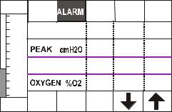
ALARM MENU (ALARM) monitored parameters and alarmsStandard Alarms are
Peak Pressure and Rate. The O2 alarm can be turned off.
PARAMETER RANGES AND ALARM LIMITS
|
PARAMETER |
|
|
DISPLAY RANGE |
|
LIMITS |
|
|
|
|
|
|
|
|
|
||
|
|
|
|
|
|
LOW |
|
HIGH |
|
|
|
|
|
|
|
|
|
|
Peak Pressure cmH2O |
0-125 |
|
0-124 |
|
1-125 |
||
|
Rate bpm |
0-199 |
|
0-159 |
|
1-160 |
||
|
O2 |
0-100 |
|
0-100 |
|
1-105 |
||
|
|
|
|
|
|
|
|
|
ADDITIONAL ALARMS OUTSIDE OF THE ALARM MENUS
MODALITY |
CONDITION |
INDICATED BY FLASHING |
|
|
|
ALL MODES |
INSPIRATORY <0.1 SEC. |
INSPIRATORY DISPLAY |
|
|
|
ALL MODES |
INSPIRATORY >3.0 SEC. |
INSPIRATORY DISPLAY |
|
|
|
ALL MODES |
EXPIRATORY <0.2 SEC. |
EXPIRATORY DISPLAY |
|
|
|
ALL MODES |
I/E >3:1 |
I/E DISPLAY |
|
|
|
ALL MODES |
NO EXTERNAL POWER |
BATTERY KEY |
|
|
|
ALL MODES |
LOW BATTERY POWER |
BATTERY KEY |
|
|
|
NOTES REGARDING ALARMS:
RATE- The monitored rate is calculated and displayed as a rolling average over 10 breaths.
HIGH PEAK PRESSURE- Inspiratory is terminated if the peak pressure reaches the high limit as set except for sigh breaths. During sigh breaths the high peak pressure limit is increased by 1.5 times the display setting (up to 125 cmH2O).
PEEP/CPAP- displays CPAP when in CPAP mode and PEEP in other modes.
DEACTIVATING ALARMS- The alarm for O2 may be turned off by scrolling the low limit down past zero to Off.
21
III.USER INTERFACE, CONNECTIONS AND SPECIFICATIONS- cont.
B- INFORMATIONAL DISPLAYS AND INDICATORS 1- DOT MATRIX GRAPHICS LCD.
Backlighting enhances the display, but it may be turned off to reduce battery power consumption. It is divided into sections which include the following displays and indicators:
AIRWAY PRESSURE BAR GRAPH-Provides an analog readout in proximal airway pressure from 0 to +110 cmH2O. It has no moving parts. Above and below the bar graph are numerical values for PEAK and PEEP/CPAP pressures respectively.
FLOW WINDOW- Displays the inspiratory flow set with the Flow knob control.
WARNING: When using the Crossvent with an air/oxygen blender, there may be a reduction in the delivered flow at the higher flow settings. This reduction may occur when the blender is set below 30% or above 90% O2 and the Crossvent is set to flows above 80 lpm. Lower supply pressures to the blender will tend to decrease the flow further so be sure these supply pressures are maintained at 4575 PSI (310-517 kPa). An external spirometer is recommended to verify the flow.
I/E RATIO WINDOW- Displays the ratio of inspiratory time to expiratory time. This display flashes and an audible alarm sounds whenever: the I/E ratio is greater than 3 to 1, whenever the inspiratory time is greater than 3 sec. or less than 0.1 sec. or whenever the expiratory time is less than 0.2 sec. The alarm may be silenced temporarily by pressing ALARM QUIET. It may be permanently silenced only by rectifying the timing limit violation.
INSPIRATORY SOURCE WINDOW:
SPONTANEOUS- Displays SPONT whenever an inspiration is initiated by the patient’s spontaneous effort during SIMV or CPAP, delivered at PEEP or atmospheric pressure or pressurized when pressure support is on.
ASSISTED- Displays ASSIST whenever an inspiration is initiated by the patient’s spontaneous efforts and delivered under pressure (volume or pressure limited breath), during Assist Control and SIMV breaths.
CONTROLLED- Displays CONTROL whenever an inspiration is initiated by the CROSSVENT-3 timer (volume or pressure limited breath), during Assist
Control, SIMV backup and CPAP backup breaths.
POWER SOURCE WINDOW:
EXTERNAL POWER- Displays “EXTERNL POWER” whenever external power is connected to the CROSSVENT-3.
BATTERY OPERATION- Flashes “BATTERY” whenever external power is lost and the CV-3 is operating on battery. A simultaneous audible alarm sounds which may be silenced only by pressing the Power Source window. The Power Source window also displays a bar graph which decreases in 20% increments. Restoration of external power will automatically switch the unit to external power operation and begin charging of the battery until full charge is
22
III.USER INTERFACE, CONNECTIONS AND SPECIFICATIONS- cont.
reached.
WARNING: If the battery has not been periodically refreshed, the amount of time the Crossvent will operate on battery power may be substantially reduced even though it indicates a full charge (see Section III, Part C-3).
WARNING: Always operate the CV-3 on battery prior to use to confirm that the battery is functioning.
WARNING: Although the Crossvent will operate with an external power source from 12 – 28 VDC, when at 12 volts the battery will not charge.
CAUTION: It is recommended that the CROSSVENT-3 never be left with its battery discharged as this will reduce battery life. After discharge of the battery, recharge fully before disconnecting the plug-in power supply. For maximum battery life, periodically discharge the battery fully and then recharge.
Low BatteryFlashes “BATTERY LOW” and sounds the audible alarm while at least 20 min. of autonomous operation remains. The audible alarm may be permanently silenced by pressing the Power Source window. The ventilator should be switched to external power or removed from service and recharged when this alarm occurs. If the battery is allowed to expend energy to a point below 6 volts (well below the Low Battery alarm limit), the ventilator will shut down independent of the On/Off switch. If this occurs, the external power supply must be used to recharge the battery and the On/Off switch must be turned to Off and then back to On before the unit will operate.
NOTE: 20 minutes of operation after low battery alarm assumes a properly maintained battery in good condition.
ENTRAINMENT ON WINDOW- Indicates “ENTRN” when entrainment is on.
2 - AUDIBLE TONE GENERATOR
Located next to the BMD logo on the front of the unit (Fig. 1), it emits the audible tones to indicate an alarm condition or keyboard actuation. The tone for a standard alarm is rated at 90 dB.
WARNING: It should never be obstructed.
3 - ALARM LED
It flashes during any alarm providing 360-degree visibility. When unit is turned off or loses power, it lights intermittently for 3 minutes. This time may be less if the Crossvent was not powered on for at least 5 minutes prior to loss of power.
23
III.USER INTERFACE, CONNECTIONS AND SPECIFICATIONS- cont.
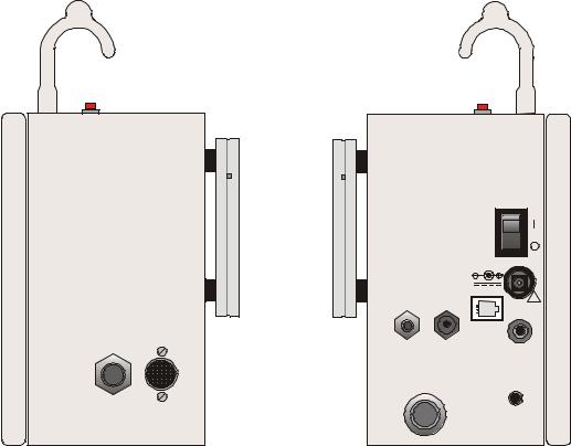
C- CONNECTORS & MISC.
POWER
ON
OFF
!
AIR/OXYGEN |
BLEED |
RS232 |
|
EXHAUST |
|
|
|
SUPPLY INLET |
EXH |
AIRWAY |
O2 |
|
VALVE |
PRESSURE |
|
|
PATIENT |
|
|
44 -66 PSI |
DO NOT |
|
|
304-455kPa |
|
ALARM |
|
MAX. FLOW-132 LPM OBSTRUCT |
|
||
|
|
|
RESET |
Fig. 5 - SIDE VIEWS
CAUTION: Antistatic or electrically conductive hoses or tubing should not be used.
1.Right side
GAS SUPPLY INLET- Male DISS 9/16-18 fitting. Clean, dry, medical grade gas, delivered at 44 to 66 psi (304 – 455 kPa) pressure at 132 lpm is required.
If an air/oxygen blender is used, then 45 – 75 PSI (310 – 517 kPa) should be supplied to the blender.
2. Left side
EXTERNAL ELECTRICAL SUPPLY CONNECTOR- This receptacle accepts the plug from the factory supplied, U.L. approved, wall plug-in, power supply module which by necessity meets all the specifications and standards listed in Section III, Part D. Use only Jerome Industries model WSZ116M (16VDC, 3A).
The Crossvent should not be used with any other wall plug-in or desktop AC adapter. This is used to operate the ventilator and to charge the battery whenever it is below full charge. The wall plug-in power supply is furnished for 117 VAC, 60 Hz or 220 VAC, 50 Hz operation, as required. It is not possible to overcharge the battery. In order to maximize battery life, periodically discharge the battery fully and then recharge (see Section III, Part C-3). Additionally, always keep the battery fully charged when not in use.
WARNING: Although the Crossvent will operate with an external power source from 12 – 28 VDC, when at 12 volts the battery will
24
III.USER INTERFACE, CONNECTIONS AND SPECIFICATIONS- cont.
not charge.
CAUTION: When using an AC power source, only the power supply provided with the Crossvent is approved for use with this ventilator. Any other power supply may cause damage and/or unreliable operation.
CAUTION: Any more comprehensive DC power supply than that which is supplied must be short circuit protected and must comply with all of the specifications and standards as listed in Section III, Part D.
CAUTION: When it is necessary to operate the Crossvent from an AC inverter, only inverters in compliance with NEMA standards should be used (see Addendum 2).
PATIENT GAS CONNECTOR- The main patient corrugated hose is attached here. It provides the un-humidified breathing gas mixture to the patient circuit.
EXHALATION VALVE CONNECTOR- Provides the pressure signal to operate the exhalation valve. During inspiration it applies a high pressure signal to the exhalation valve diaphragm which sets the Maximum Pressure Limit. During expiration it provides a zero or PEEP level to the exhalation valve diaphragm.
25

III.USER INTERFACE, CONNECTIONS AND SPECIFICATIONS- cont.
AIRWAY PRESSURE CONNECTOR- Provides connection of the proximal airway pressure tube to the internal pressure transducer. This allows the CROSSVENT-3 to monitor airway pressure and also to detect patient inspiratory efforts.
OXYGEN SENSOR CONNECTOR (use is optional)- Permits attachment of the O2 fuel cell sensor. This provides measurement of the oxygen concentration of the patient breathing gas mixture.
WARNING: For proper operation only the O2 sensor supplied by Bio-Med Devices may be used.
RS-232 COMPUTER INTERFACE (use is optional)- A 6 pin, modular jack is provided as a convenient PC interface for software updates.
3- Rear of Unit
BATTERY- The battery is located
internally. In order to maximize battery life, periodically refresh the battery as described here. Additionally, always keep the battery fully charged when not in use.
To properly maintain and refresh the battery, it is important to periodically
fully discharge and then fully recharge it. To do this, first unplug the external power supply from the side of the Crossvent if it is plugged in. Turn the Crossvent on and press the TEST key in the bottom row of the display. Press VALVES and
press ON for each valve. (Putting it
in test mode will prevent any alarms from sounding and hasten the process by having the backlight and valves on). Leave it this way until the display is blank.
This indicates the battery is exhausted. This may take several hours depending on the state of the battery when you begin.
CAUTION: Turn off the unit for at least one minute prior to plugging in the external power supply after a full discharge.
Plug the external power supply back into the side of the unit and into a wall outlet and charge the battery for a minimum of 4 hours. When done, verify battery power by unplugging the external power cord from the side of the unit while it is turned on. The Crossvent should alarm and the power source key in the bottom row should be flashing. Press this key to silence the alarm. The battery bar indicating the remaining battery power should span the entire battery key.
WARNING: If the battery has not been periodically refreshed, the amount of time the Crossvent will operate on battery power may be substantially reduced even though it indicates a full charge.
WARNING: Never operate the CROSSVENT-3 without a battery since it will fail to operate if the plug-in power supply is removed. WARNING: Although the Crossvent will operate with an external power source from 12 – 28 VDC, when at 12 volts the battery will
26
III.USER INTERFACE, CONNECTIONS AND SPECIFICATIONS- cont.
not charge.
CAUTION: The battery should be placed at least every two years. Only use batteries supplied by Bio-Med Devices, part #PRT4402. Do not substitute.
MAXIMUM PRESSURE RELIEF VALVE- A preset, relief valve exits the rear of the unit. This valve establishes the maximum safety pressure deliverable. It is set at 120 cmH2O.
WARNING: It should never be obstructed.
NEGATIVE PRESSURE RELIEF VALVE- A preset, negative pressure valve also exits the rear of the unit. It allows the patient to breath ambient air if the entire system should become inoperative. It opens at approximately -4 cmH2O.
WARNING: It should never be obstructed.
WARNING: Should the use of the negative pressure relief valve become necessary, the operation of the Crossvent in a contaminated environment can be hazardous.
CE MARK- The CE mark displayed on this product signifies that this device is in compliance with the European Medical Devices Directive (Council Directive
93/42/EEC). As a prerequisite for the CE mark, Bio-Med Devices operates under an ISO 13485 compliant quality system (covering the design and manufacture of medical devices). The four-digit code underlying the CE mark (0086) pertains to Bio-Med's Notified Body, the British Standards Institute, whose function is to investigate and attest to the validity of CE-mark claims.
EU Classification: Internally-powered equipment
Continuous operation
BF type applied part
Not suitable for AP or APG
27
Loading...