

Page 1

Service Manual of S10&S12 Patient Monitor
S10&S12 Patient Monitor
Service Manual
GuangDong Biolight Meditch Co,.ltd
No.2 Innovation First Road, Technical Innovation Coast, Hi-tech Zone, Zhuhai , P.R.China
http://www.blt.com.cn
Page 2

Service Manual of S10&S12 Patient Monitor
1
CONTENTS
Chapter 1 Summary..................................................................................................... 2
1.1 About the Manual.................................................................................................................... 2
1.2 Safety Information...................................................................................................................3
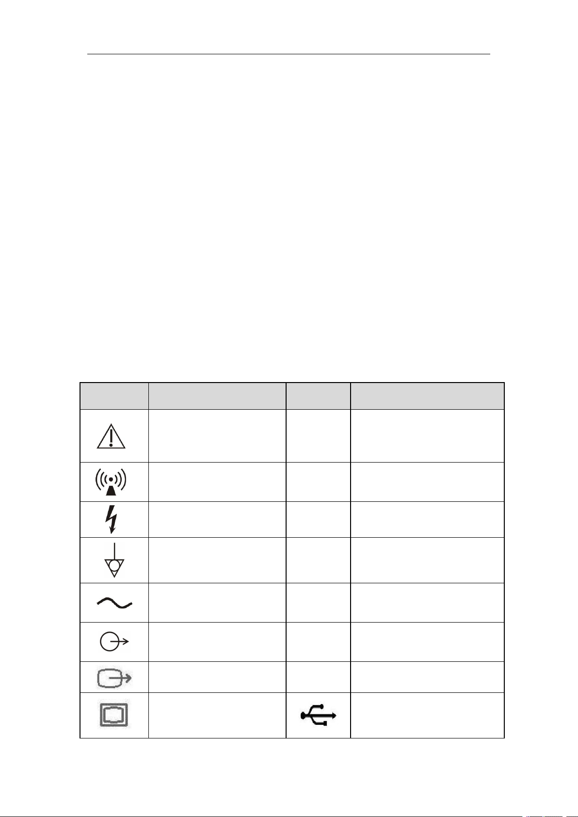
1.3 Equipment Symbols................................................................................................................ 4
Chapter 2 Monitor Introduction.................................................................................6
2.1 Main Frame............................................................................................................................. 6
2.2 Accessories.............................................................................................................................. 9
Chapter 3 Testing....................................................................................................... 18
3.1 Brief Introduction..................................................................................................................18
3.2 General Testing......................................................................................................................18
3.3 Performance Testing..............................................................................................................19
Chapter 4 Maintenance..............................................................................................23
4.1 Maintenance Menu................................................................................................................23
4.2 NIBP maintenance.................................................................................................................26
4.3 Software Upgrade..................................................................................................................29
Chapter 5 Troubleshooting........................................................................................31
5.1 Overview............................................................................................................................... 31
5.2 Common Failure Analysis and Trouble-shooting.................................................................31
Chapter 6 Maintenance and Disassembling.............................................................33
6.1 Tool........................................................................................................................................33
6.2 Disassemble Procedure......................................................................................................... 33
Appendix..................................................................................................................... 41
Page 3

Service Manual of S10&S12 Patient Monitor
2
Chapter 1 Summary
1.1 About the Manual
1.1.1 Notes
This service manual introduces in detail the hardware composition, assembling,
disassembling, testing and trouble-shooting of this product and its relevant spare parts
so as to facilitate the maintenance personnel to handle common failures more
effectively. This service manual does not provide profound introduction on the
product’s structure and design mechanism, and in case of unsolvable problems, please
contact the after-sale department of our Company.
This service manual introduces the product based on its basic configuration;
therefore, part of its content may not apply to the product that you maintain. In case of
any queries, please contact the after-sale department of our Company.
Prior to product maintenance, you are kindly requested to carefully read this
service manual, and ensure that you have fully understood its content so as to
guarantee that maintenance work can be executed appropriately to avoid causing
product or personal damages.
1.1.2 Users of the Manual
This manual is targeted to technicians, maintenance workers of biomedical
instruments and after service commissaries.
1.1.3 Intended Use
The monitor is intended to be used for monitoring, displaying, reviewing, storing
and alarming of multiple physiological parameters of patients, including ECG, ST
segment analysis, arrhythmia analysis, Heart Rate (HR), Respiration Rate (RR),
Temperature(Temp), Pulse Oxygen Saturation(SpO2), Pulse Rate(PR), Non-invasive
Blood Pressure(NIBP), Invasive Blood Pressure(IBP), Carbon dioxide(CO2), Cardio
Output(C.O.).
The monitor is intended to be used ICU, PICU,NICU,OR, ER, general ward and
so on.
Warning:
The monitor is intended for use only by clinical Professionals or under their
guidance. It must only be used by persons who have received adequate training
Page 4

Service Manual of S10&S12 Patient Monitor
3
in its use. Anyone unauthorized or untrained must not perform any operations
on it.
1.2 Safety Information
1.2.1 Terms
The terms in the manual (e.g. danger, warning, caution, and note) point out the
hazard, and inform users of the issues they should pay attention to during the
operations according to different degrees of severity.
Danger
It indicates urgent danger, which, if not avoided, might cause death, severe
personal harms or property loss.
Warning
It indicates potential dangers or unsafe maintenance operations, which, if not
avoided, might cause death, severe personal harms, product damage or property loss.
Caution
It indicates unsafe maintenance operations, which, if not avoided, might cause
slight personal harms, product damage or property loss.
Note
It emphasizes important notes, provides explanations or interpretation so as to
better service this product.
1.2.2 Danger
This Manual does not involve any indicative information of danger class.
1.2.3 Warning
Only the Company’s authorized professional maintenance personnel can
disassemble the monitor.
Before Disassembling the monitor, make sure the AC power code unplug, and
batteries are removed, so as to avoid high-voltage electric shock.
Please connect the monitor to a socket with protective earth. If the socket does
not have protective earth conductor, please do not use the socket and use battery to
provide power to the monitor
Keep the packing materials out of children’s reach. Disposal of the packing
materials should observe the applicable waste control regulations.
Page 5
Service Manual of S10&S12 Patient Monitor
4
Symbol
Symbol Note
Symbol
Symbol Note
Attention: Consult
accompanying documents
(this menual).
ECG
Short for
Non-ionizing radiation
SpO2
Short for “Pulse Oxygen
Saturation”
Dangerous voltage
TEMP
Short for “Temperature”
Equipotential grounding
IBP
Short for “Invasive Blood
Pressure”
Alternating current
NIBP
Short for “Non-invasive Blood
Pressure”
Auxiliary output
connector
CO
2
Short for “Carbon dioxide”
DVI display connector
C.O.
Short for “Cardio Output”
VGA display connector
USB socket
1.2.4 Caution
When the monitor is conducting some performance tests, make sure the monitor
will not be interfered by electromagnetic radiation. Mobile phones, X rays or MRI
equipment are all possible interference sources, because they can produce
high-intensity electromagnetic radiation.
Before energizing the monitor, make sure the voltage and frequency of the power
conform to the requirements specified in the label on the monitor or in this Manual.
During maintenance, pay attention to preventing the monitor from falling, being
knocked, or intensely shaken or damaged by other mechanical forces.
1.2.5 Note
For the detailed operation and other information, please refer to the User’s
manual.
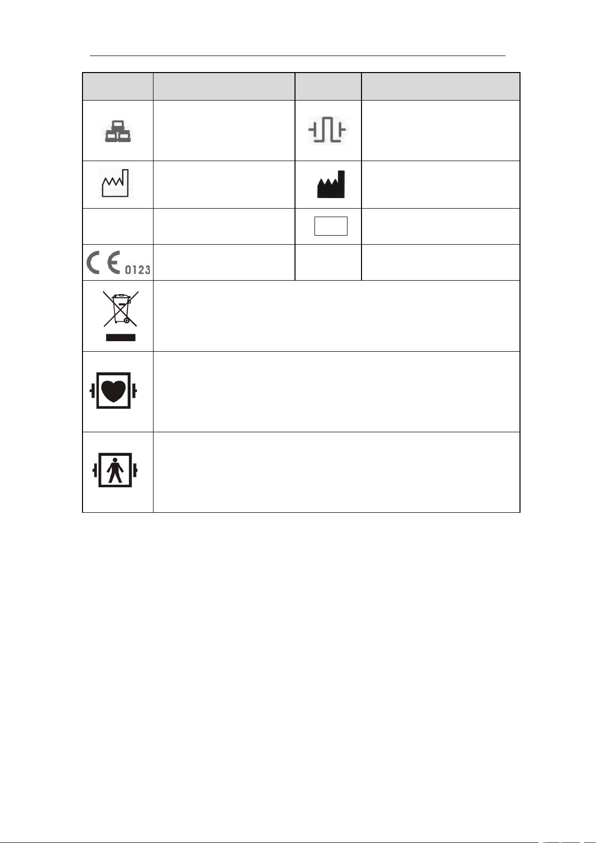
1.3 Equipment Symbols
Page 6
Service Manual of S10&S12 Patient Monitor
5
Symbol
Symbol Note
Symbol
Symbol Note
Network connector
Defibrillator
synchronization output
connector
.
Manufacture date
Manufacturer
SN
Serial number
REF
Catalog number
CE mark
Symbol for the marking of electrical and electronics devices according to
Directive 2002/96/EC.
Type CF applied part, defibrillation protected
The unit displaying this symbol contains an F-Type isolated (floating)
applied part providing a high degree of protection against shock, and is
defibrillator-proof.
Type BF applied part, defibrillation protected
The unit displaying this symbol contains an F-Type isolated (floating)
applied part providing a high degree of protection against shock, and is
defibrillator-proof.
Page 7
Service Manual of S10&S12 Patient Monitor
6
Chapter 2 Monitor Introduction
2.1 Main Frame
2.1.1 General Introduction
The monitor is intended to be used for monitoring of multiple physiological
parameters of patients, including ECG, ST segment analysis, arrhythmia analysis,
Heart Rate (HR), Respiration Rate (RR), Temperature(Temp), Pulse Oxygen
Saturation(SpO2), Pulse Rate(PR), Non-invasive Blood Pressure(NIBP). Besides, it
can upgrade to Invasive Blood Pressure(IBP), Carbon dioxide(CO2), Cardio Output
(C.O.) and Drip Monitor (DM)
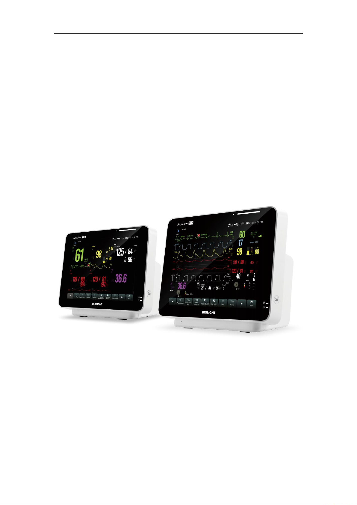
Over view
S10 S12
This monitor also provides the following functions:
Conduct visual and audio alarms on patients’ physiological abnormalities and
equipment’s technical problems.
Conduct real-time display, review, storage, and output of the monitored
parameters or waveforms.
Multiple operation input mode, including, touch-screen and mouse.
Wire connection with CMS system provided.
Options : DM module, recorder, trolley,wall mount,Large capacity battery act.
Page 8
Service Manual of S10&S12 Patient Monitor
7
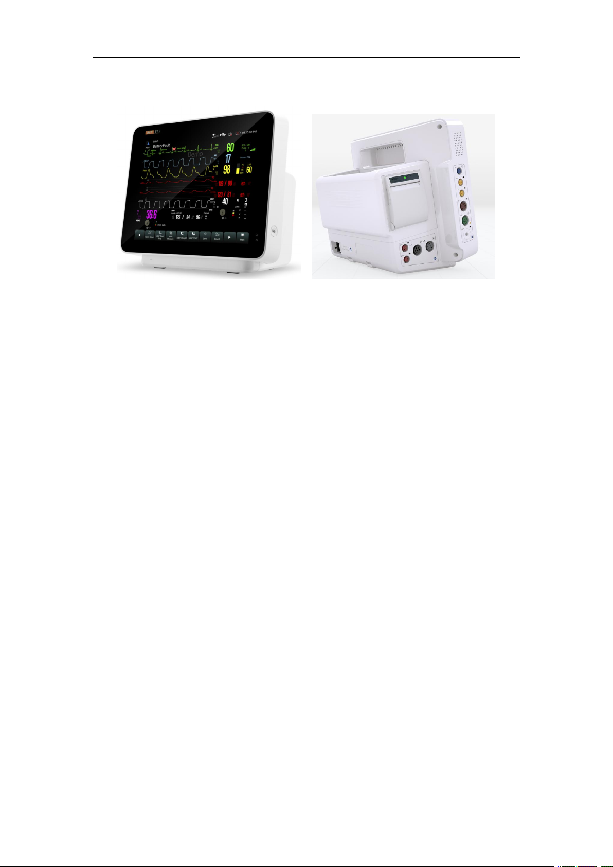
2.1.2 Appearance, interfaces
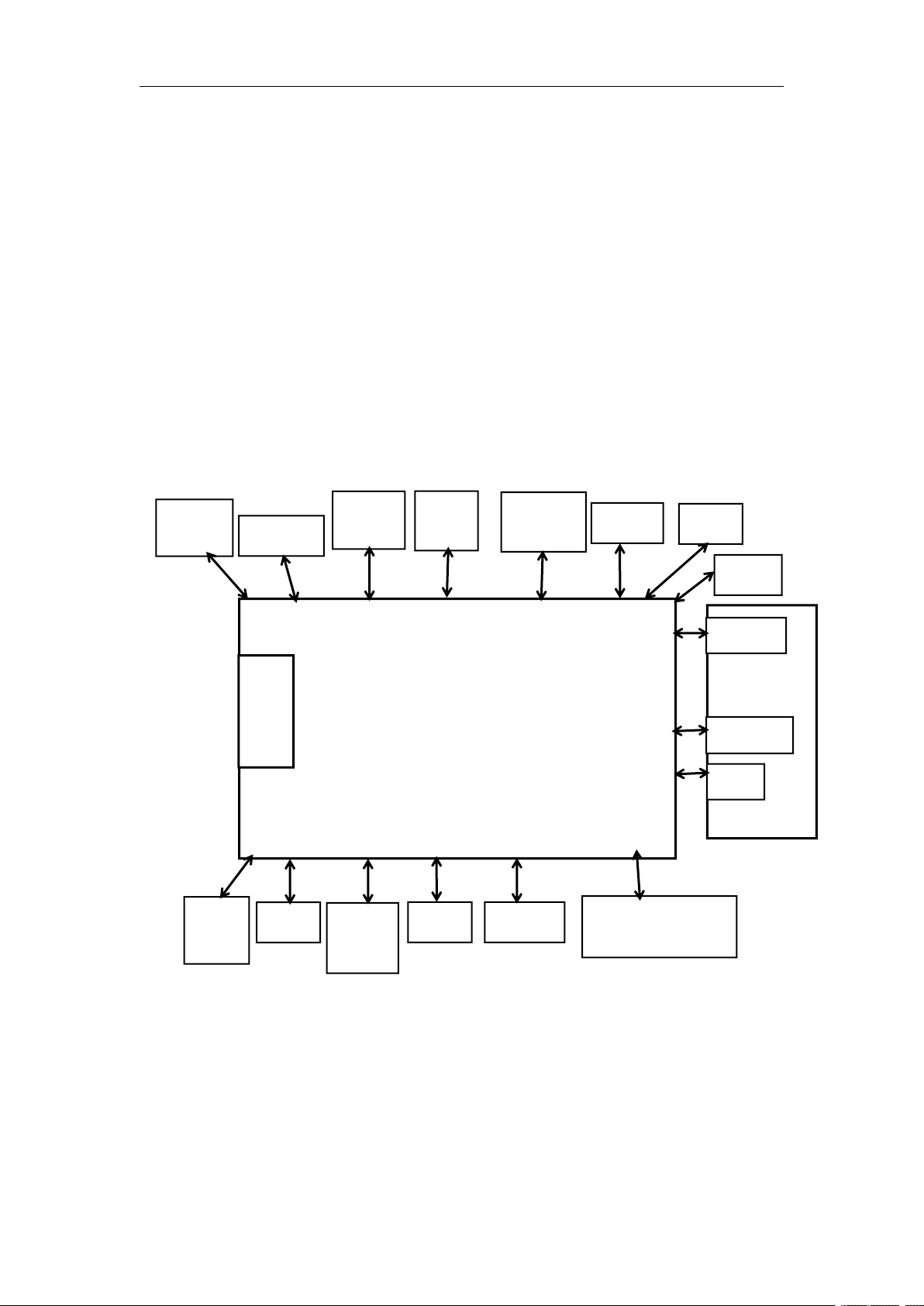
2.1.3 Hardware Structure
The monitor is composed of the following parts:
Input system: touch-screen, power switch
Output system: display screen, alarm indicator board, recorder, loudspeaker
Processing and communication system: main-board
Power management system: battery and power supply module
Equipment interface system: connector panel A/B (ECG, SpO2,NIBP, TEMP) ,
connector panel C (2-IBP,CO2, C.O.)
2.1.3.1 Input System
Touch-screen
The touch-screen is capacitive screen, supports touch control function,easy
to operate. It can be calibrated and connected with the main-board.
Mouse
The monitor can connect a mouse to operate.
Power switch and indicator board
It has three groups of LEDs used for indicating the status of AC power and
battery. It is connected with main-board.
2.1.3.2 Output System
Display
The monitor has a built-in high-brightness LCD display.The display is connected
with the main-board.
Alarm light
The monitor comprises two kinds of alarm lights: physiological alarm lights and
Page 9

Service Manual of S10&S12 Patient Monitor
8
technical alarm lights. The physiological alarm lights can emit light in two colors of
yellow and red and technical alarm lights can emit light in blue color. They both
support different flashing frequencies.
Recorder
The recorder receives the data transmitted by the main-board and then transmits
the data to the thermal print head for print-out. The front panel of the recorder has an
orange indicator (it lights up when an alarm or error occurs) and a green indicator (it
lights up during normal operation).It is connected with the main-board.
Loudspeaker
The loudspeaker is used for sounding alarm, touch tones, heartbeat tones and
pulse tones and is supports the multi-volume function. It is connected with the
main-board and its DC power is supplied by the main-board.
2.1.3.3 Processing and Communication System
Main-board
As the heart of the monitor, the main-board accomplishes such a series of tasks
as input and output control, data storage and processing, display processing, system
control, communications management, printing management and failure alarm.
2.1.3.4 Power Management System: Battery, Power Module
Battery
the monitor supports DC power supply, and can use two types of rechargeable
lithium batteries: 11.1V/5000mAh and 11.1V/2500mAh. Working time up to 4 hours
(2500mAh) or 8 hours (5000mA) (One new fully charged battery with a temperature
of 25 ℃, ECG, SpO2 are connected, and NIBP in automatic mode at intervals of 30
minutes);
Power module:
AC: 100-240V (±10%), 50/60Hz, ≤100VA;
2.1.3.5 Equipment Interface System:
connector panel A/B (DM,ECG, SpO2,NIBP, 2-TEMP);
connector panel C (2-IBP, CO2, C.O.);
Interfaces on main board(VGA,USB, RJ45,SCSI);
1) VGA interfaces: It can be connected with VGA video output;
2) Network interface: It is networked with the central monitoring system via
the internet;
3) USB interface: It can connect with mouse and keyboard to facilitate the
Page 10
Service Manual of S10&S12 Patient Monitor
9
Backlight
(S10)
Speaker
Pump
connector
panel A/B
ECG
DM module
SpO2/TEMP
Recorder
Touch
screen
Alarm
light
valves
Power
supply
Power
switch
J25
J20
J33
J34
J4
J14
J21
J24
J23
J28
J27
J26
J1
J11
connector panel C
CO/IBP/CO2
VGA
2-USB
RJ45
SCSI
Main board
4G module
Backlight
(S12)
J15
Battery
J7/J30
LCD
J8
operation and entry of relevant information; Software update, supply the power
to WiFi module and so on;
4) SCSI Interface:
* Defibrillation synchronous output/Analog output interface: it is connected
with the defibrillation device and sends defibrillation synchronous signals. And
also connected to device, such as oscilloscope and sends analog signals.
* Nurse call output interface: It can be connected with the hospital’s call
system, which, in case of an alarm, sends out a nurse call signal to alert the
nurses.
2.1.4 Design Principle
Schematic diagram:
2.2 Accessories
2.2.1 General Accessories
General accessories mostly contains ECG cable,SpO2 sensor, NIBP cuff,
Temperature probe, in addition, it contains mainstream CO2 measurement groupware,
micro stream CO2 measurement groupware, C.O. interface cable and pulmonary
Page 11
Service Manual of S10&S12 Patient Monitor
10
artery catheter. More than this, the monitor also could install trolley, wall mount, and
rechargeable lithium.
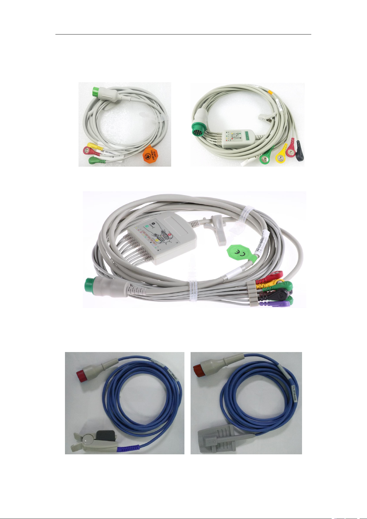
1. ECG cable
12PIN 3-lead ECG cable (IEC) 12PIN 5-lead ECG cable (IEC)
(15-031-0013) (15-031-0002)
12pin12-lead ECG cable (IEC)
(15-031-0001)
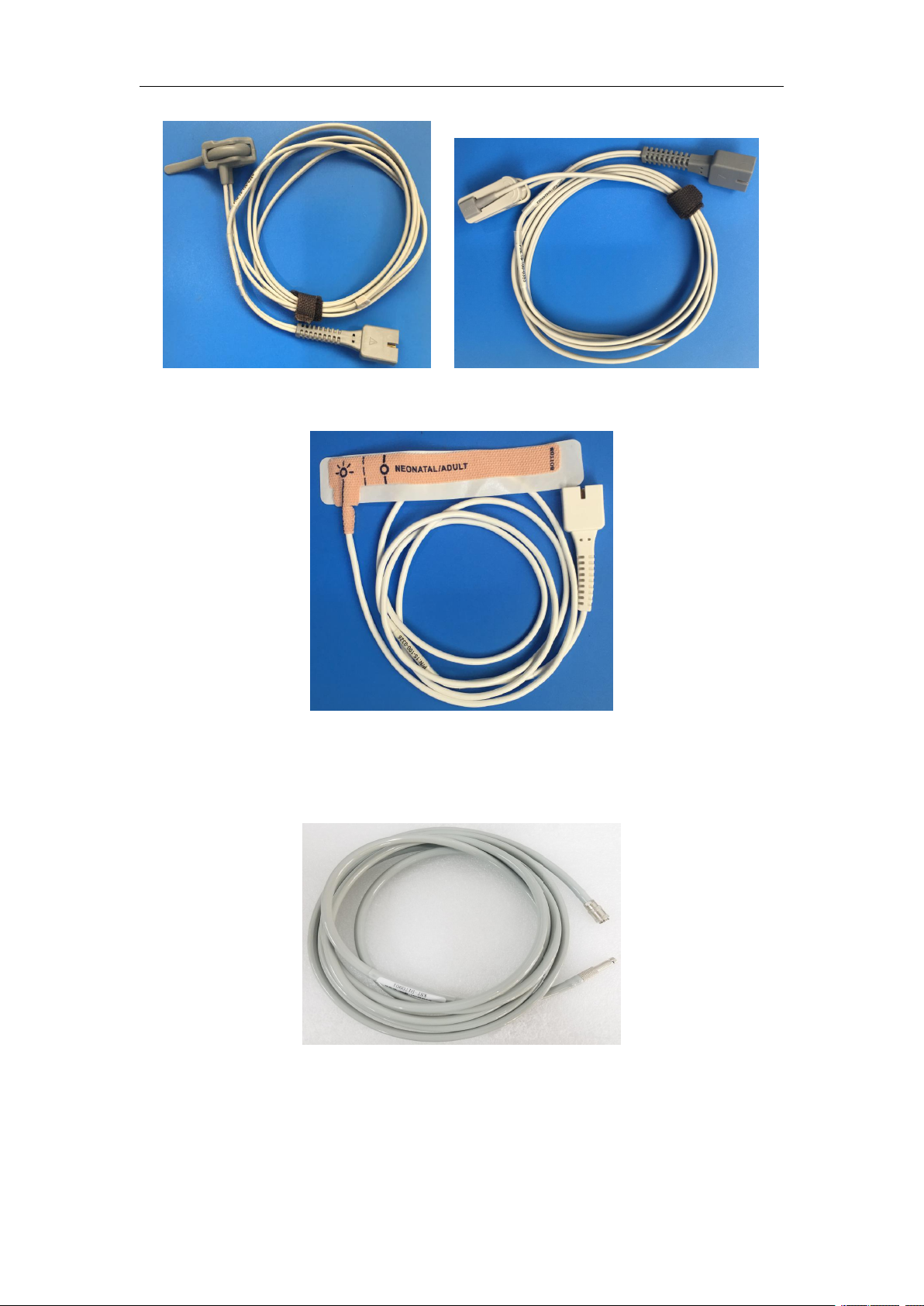
2. SpO2 probe and extension
analog SpO2 adult reusable sensor analog SpO2 adult soft reusable sensor
(15-100-0358) (15-100-0359)
Page 12

Service Manual of S10&S12 Patient Monitor
11
analog SpO2 extension cable
(15-100-0357)
analog SpO2 adult reusable sensor (9pin ) analog SpO2 adult soft reusable sensor(9pin)
(15-100-0320) (15-100-0321)
analog SpO2 pediatric reusable sensor(9pin) analog SpO2 pediatric soft reusable sensor(9pin )
(15-100-0322) (15-100-0360)
Page 13
Service Manual of S10&S12 Patient Monitor
12
analog SpO2 neonatal reusable sensor (9pin) analog SpO2 reusable Y multi-site sensor(9pin)
(15-100-0324) (15-100-0353)
analog SpO2 neonatal/adult disposable sensor (9pin)
3. PVC tube & Cuff
(15-100-0326)
NIBP PVC tube
(15-031-0008)
Page 14

Service Manual of S10&S12 Patient Monitor
13
Neonatal Cuff M5121(6cm-11cm) Infant Cuff(M5122-2)(10cm-15cm)
(15-100-0122) (15-100-0155)
Child Cuff (M5122-1)(14cm-20cm) Pediatric Cuff M5123(18-26cm)
(15-100-0154) (15-100-0121)
Adult Cuff M5124(25cm-35cm) Large Adult Cuff M5125(33cm-47cm)
(15-100-0118 ) (15-100-0120)
Adult Thigh Cuff M5126(44cm-53cm) Neonatal disposable Cuff pack M5541(1#,2#,3#,4#)
(15-100-0142 ) (15-100-0104/105/106/107)
Page 15
Service Manual of S10&S12 Patient Monitor
14
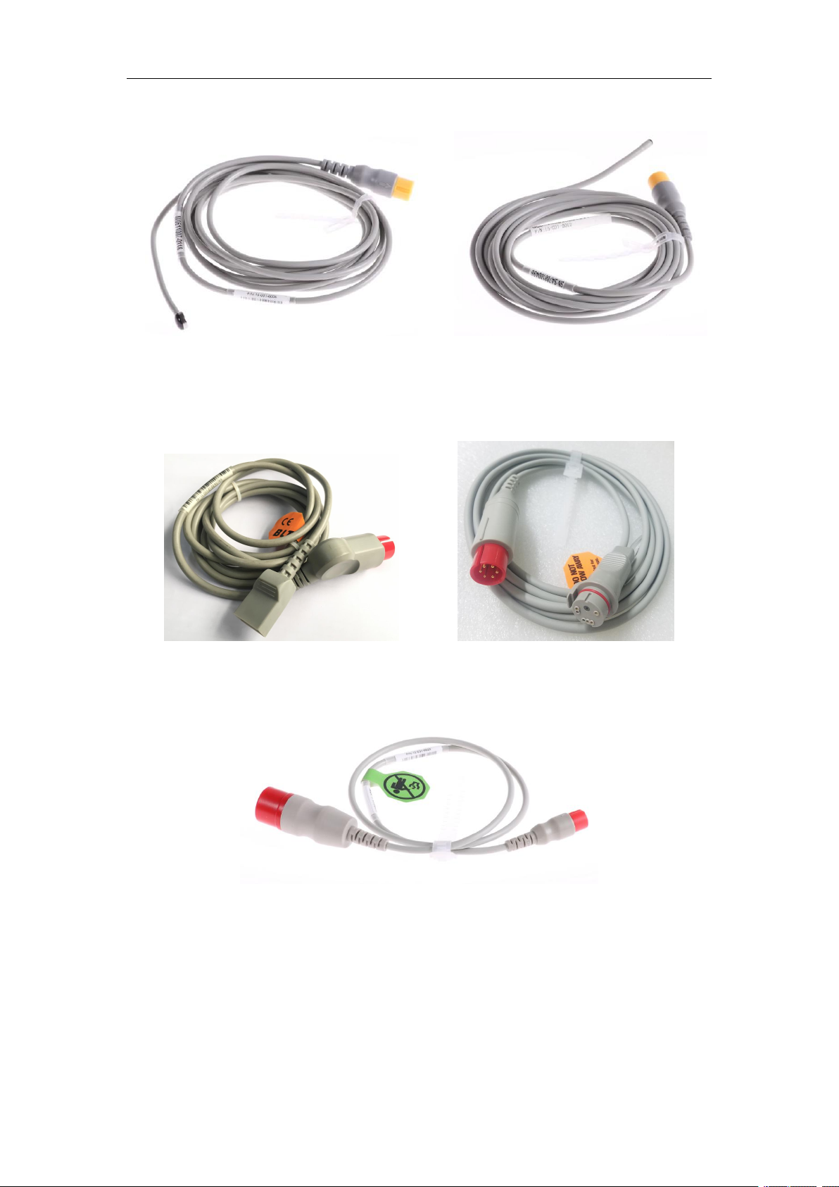
4. TEMP sensor
TEMP skin probe TEMP Rectal/ Esophageal probe
(15-031-0005) (15-031-0015)
5. IBP interface cable
IBP transducer interface cable(UTAH) IBP transducer interface cable(BD)
(15-100-0029 ) (15-100-0032)
4 pin to 6pin IBP extension connector (15-031-0023)
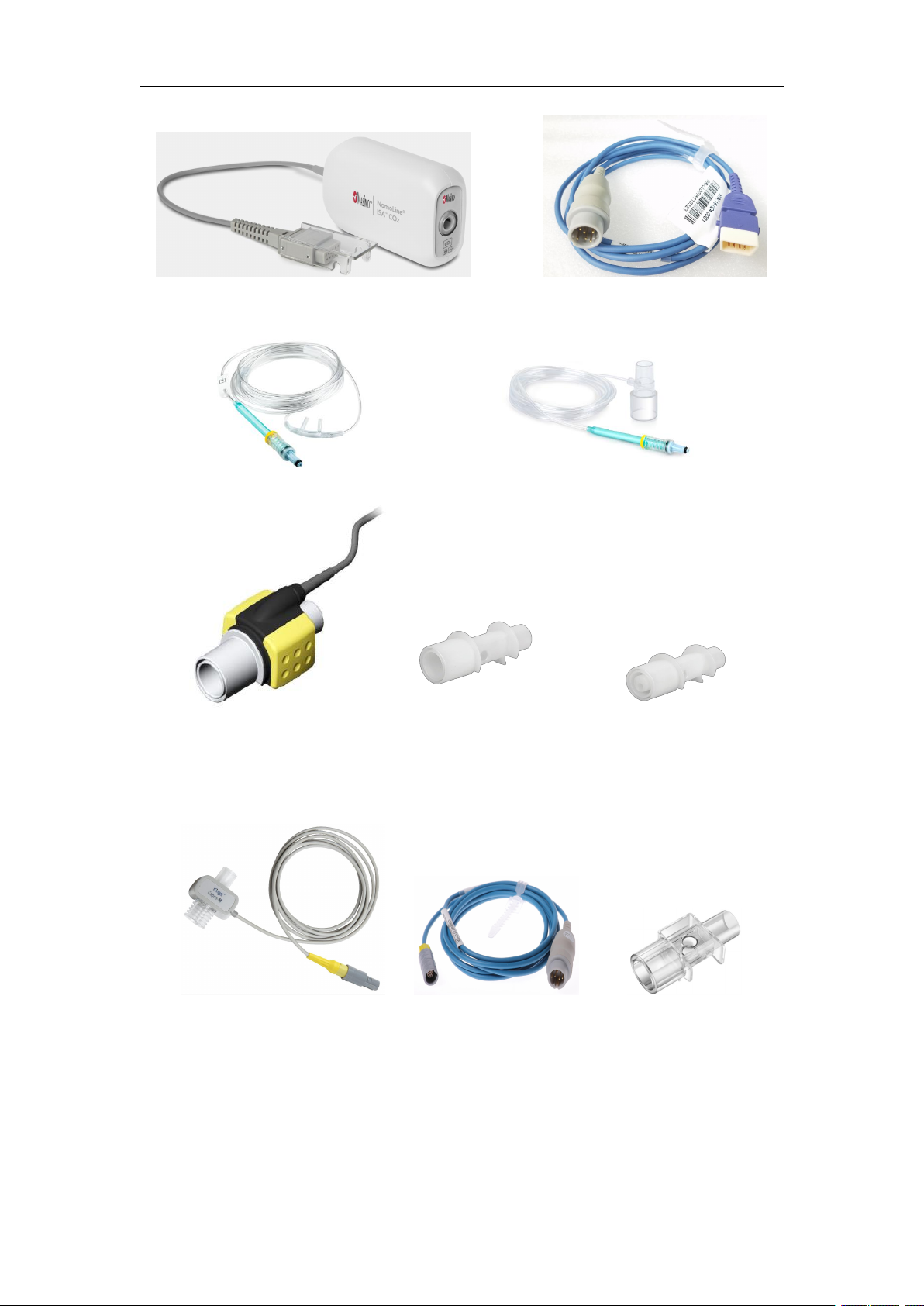
6. CO2 sensor (Masimo)
Page 16
Service Manual of S10&S12 Patient Monitor
15
ISA CO2 sensor(Masimo) CO2 extension cable(Masimo)
16-100-0116 15-031-0010
NomoLine Nasal CO2 Cannula (3830) NomoLine Airway Adapter Set (3827)
IRMA CO2 sensor(Masimo)Airway adaptor(Adult / Pediatric) Airway adaptor (Neonatal/Infant)
16-100-0017 15-100-0039 15-100-0040
7. CO2 sensor (BLT)
Capno-M CO2 sensor CO2extension cable Airway adaptor(Adult / Pediatric)
15-100-0199 15-031-0011 15-100-0212
Page 17
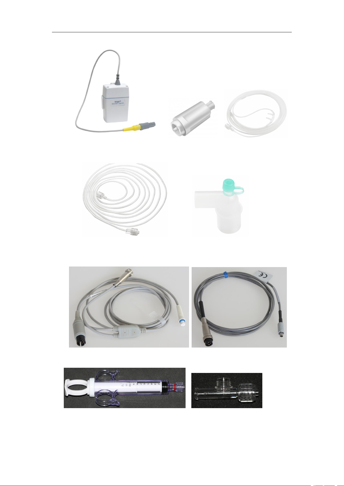
Service Manual of S10&S12 Patient Monitor
16
Capno-S CO2 swnsor CO2 filter T4F CO2 Nasal Cannula - Adult
15-100-0185 15-100-0354 15-100-0187
8. C.O.
Sampling line (15-100-0035) 3 way airway adapter (15-100-0074)
Cardiac output cable In-line Injection temperature probe (SP4042)
15-100-0148 15-100-0147
Control Syringe(12ml) In-line Injection temperature probe housing(BD SP5045)
15-100-0169 15-100-0146
9. DM module (Drip Monitor Module)
Page 18
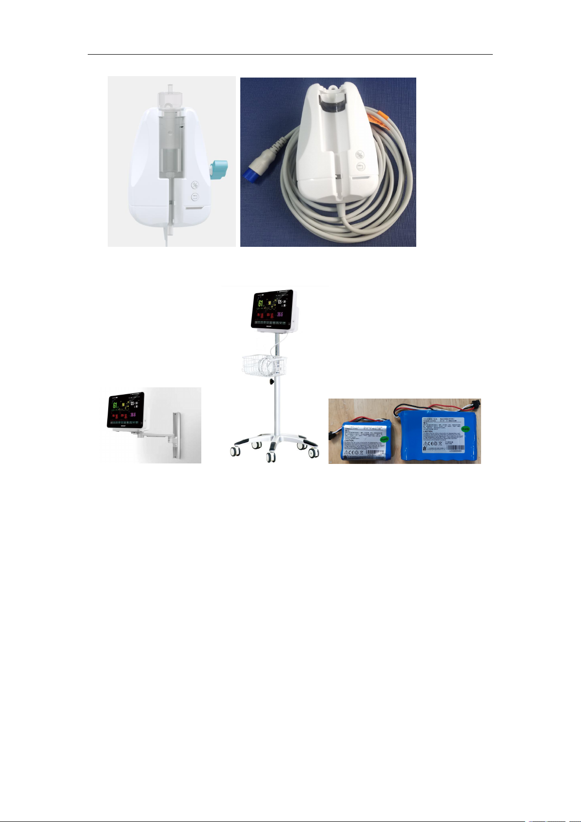
17
10. Others
Service Manual of S10&S12 Patient Monitor
DM module
Wall mount Trolley Rechargeable lithium battery(2.5A/5A)
20-100-0029 20-100-0028 12-100-0031/32
2.2.2 Management and Maintenance of Accessories
Refer to the User’s manual.
Page 19

Service Manual of S10&S12 Patient Monitor
18
Chapter 3 Testing
3.1 Brief Introduction
To ensure the long-term and stable working of the monitor, maintenance
personnel need to conduct regular checks, maintenance and testing on it. This chapter
provides the basic testing methods of the monitor and recommends the applicable
testing frequency and testing tools, and the maintenance personnel are requested to
conduct maintenance and testing on the monitor according to actual demands and
choose applicable testing tools.
The testing and verification methods provided by this chapter are mainly used for
verifying whether the monitor’s performance has reached the specification
requirements. During the tests, if the test results can not reach the requirements, it
indicates the monitor or a certain function module of the monitor has failures and they
need to be repaired or replaced. If you have any query, please contact the after-sale
department of our Company.
Caution:
All the testing must be done by qualified service personnel.
When setting up and changing the contents in the two menus of
Manage】and【Maintenance】, please be cautious, otherwise it might cause data
loss.
Prior to executing tests, the service personnel are kindly requested to ensure
the applicability of the testing tools and cables and service personnel shall be
familiar with the use of these testing tools.
【
Config
3.2 General Testing
3.2.1 Visual Check
Visual check is mainly for overall appearance check on the monitor, and if the
monitor has no obvious physical damage, visual check is qualified.
Check items are as follows:
1. Whether the host monitors’ enclosure, display screen or keys have any physical
damage.
2. Whether accessories have any physical damage, any wear or tear, whether the
Page 20

Service Manual of S10&S12 Patient Monitor
19
connector pins have any loosening or distortion.
3. Whether the peripheral interface of the monitor has any loosening or pin distortion.
4. Whether the safety labels or name plates are legible.
3.2.2 Startup Testing
Startup test is used to verify whether the monitor can be normally started to work,
and if the monitor can accomplish startup according to the following procedures, the
startup test is qualified. The procedures are as below:
1. Connect the monitor to the AC power. AC power indicator lights up.
2. Press the power switch, the technical alarm indicator lights up in blue, and the
physiological alarm indicator lights up in yellow and red in turn and then goes off, the
screen displays the startup image.
3. After the startup image disappears, the system produces a “dang” sound and goes
into the main screen; at the same time, the technical alarm light goes off.
4. The monitor goes into the system’s main screen and normal startup is completed.
Warning:
If the monitor is mechanically damaged, or if it is not working properly, do not
use it for any monitoring procedure on a patient. Contact your service personnel.
Caution:
The monitor does not have mains switch. The monitor is switched completely
only by unplugging the power cable from the AC power source. In order to
unplugging and plugging it, the socket on the wall must approximate to
monitor.
For measurements in or near the heart we recommend connecting the
monitor to the equipotential grounding system. Use the green/yellow
equipotential grounding cable and connect it to the terminal labeled with the
symbol .
3.3 Performance Testing
3.3.1 ECG Testing
Testing tool: ECG Simulator
1. connect the ECG lead wire to the simulator and monitor.
2. The setting of the simulator is as follows: HR 80 bmp, gain selection is 10mm/mV.
3. Observe whether the monitor displays correct ECG waveforms and HR.
Page 21

Service Manual of S10&S12 Patient Monitor
20
4. Adjust the ECG gains and HR values and verify whether the monitor’s ECG
waveforms and HR values have relevant changes.
3.3.2 NIBP Testing
Testing tool: BP simulator
1. Insert the NIBP pvc tube plug into the NIBP socket of monitor and make sure in
good contact.
2. Connect the other side of the tube to the simulator, and the simulator’s
configuration: preset: 120/80 (93), cuff: internal Adult.
3. Measure blood pressure; observe whether the measured value and the set value of
the simulator. (generally within 3mmHg).
3.3.3 SpO2 Testing
Testing tool: SpO2 simulator
1. Plug the SpO2 sensor tightly into the SpO2 socket of the monitor.
2. Connect the other side of SpO2 probe to the simulator.
3. The parameter setup in the simulator is as follows: SpO2 is 96%; pulse rate is 80
bpm.
4. Observe whether the monitor displays correct SpO2 waveforms and pulse rate.
3.3.4 TEMP Testing
Testing tool: resistance box
1. Connect the TEMP socket of monitor to two sides of the resistance box with two
cables.
2. The setup of resistance box is 1354.9Ω (the corresponding TEMP value is 37℃).
3. Observe the monitor’s display value shall not exceed 37±0.2℃
3.3.5 Resp Testing
Testing tool: ECG simulator
1. Connect the ECG cable to the simulator.
2. The setup of the simulator: base resistance is 1000 Ω;variable resistance is 1Ω
;
Resp rate is 30 rpm.
3. Observe whether the Resp waveform displayed by the monitor is normal. Resp
value shall not exceed 30±2 rpm.
Page 22

Service Manual of S10&S12 Patient Monitor
21
3.3.6 IBP Testing
Testing tool: IBP simulator
1. Connect the simulator with the IBP socket of the monitor.
2. Set the simulator to zero pressure.
3. Press the “zero” option of IBP menu to zero until the screen display “zero success”.
4. Set the monitor’s static pressure p= 200mmHg.
5. The display value of the monitor shall not exceed 200±4mmHg.
6. Set up the simulator IBP values as 120/80,120/25,120/0, 25/0, and observe whether
the waveforms and values displayed by the monitor are correct or not.
3.3.7 Recorder Testing
1. Print the ECG waveform, the recorder shall print normally and the printing is clear
and consistent.
2. In case of such failures as paper lack or paper jam, the screen shall have relevant
indication and after restoration, it shall work normally.
3. Test alarm printing of parameters, turn on the alarm record switches of the
parameters, set up different alarm limits, and in case of a parameter alarm, there shall
be the relevant printout of the parameter alarm.
3.3.8 Mainstream CO2/Microstream CO2 Testing
1. Connect the sensor to the extension, and then connect the other side of the
extension to the monitor; then the monitor will display sensor warnup
2. when the monitor display alarm message “check adapter”, then pulgin the airway
adapter (or sampling line), then alarm message disappear. then put the sensor (or
sampling line) in front of the nose and breathe, observe whether CO2 waveform and
value appear on the screen, and then put the sensor(or sampling line)still in the air,
and in 10s, the alarm message of “Apnea” is generated.
3. Remove the sensor, and the screen displays “CO2 sensor off”.
3.3.12 C.O. Testing
Testing tool: FLUKE vital sign simulator
1. Connect one terminal of the “C.O. cable” to the monitor, the other terminal connect
to the vital sign simulator, then select the simulator, enter 2.5L/min of the cardiac
output wave, 24℃ of injection and 37℃of base temperature of blood;
3. Monitor select the C.O. parameter zone to enter into the menu of【C.O. Setup】, and select the
TI Source】to manual, select the 【Setup TI】to 24℃, select 【Cath. Const】to 0.595,
【
Page 23

Service Manual of S10&S12 Patient Monitor
22
then close the 【C.O. Setup】menu.
4. Select 【C.O. Measure】,to open the C.O. measurement window, when the screen show that
“Ready for new”, select 【 Start 】 to measure the C.O., when the screen show that “Injection
now …”, enter the start key of the simulator, observe the wave, waiting for the measured
values.
5. Change the C.O. wave to 5 L/min,10 L/min , then measure again and record the measured
values.
6. The measured values compare to the value entered on simulator, the standard error
shall be ±0.2L/m.
Page 24
Service Manual of S10&S12 Patient Monitor
23
Chapter 4 Maintenance
4.1 Maintenance Menu
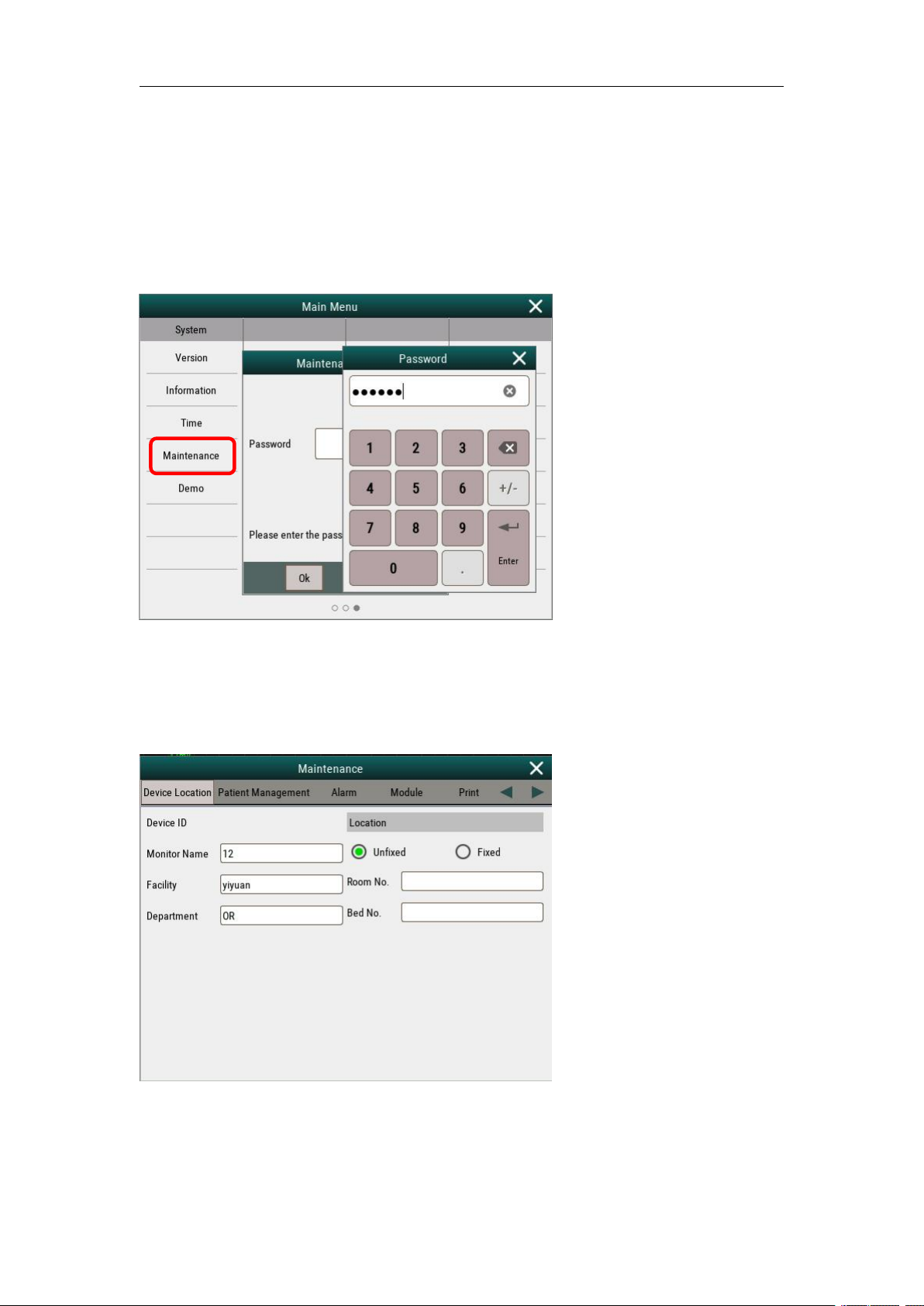
Enter 【main menu】,select【system】→【Maintenance】, input password: 785 623 , and then
enter maintenance menu:
Demo password :888 888
1. Device location
Device ID setup: set Monitor name, Unfixed or Fixed, Facility, Room No., Bed NO. and
department of Hospital.
2 Patient Management
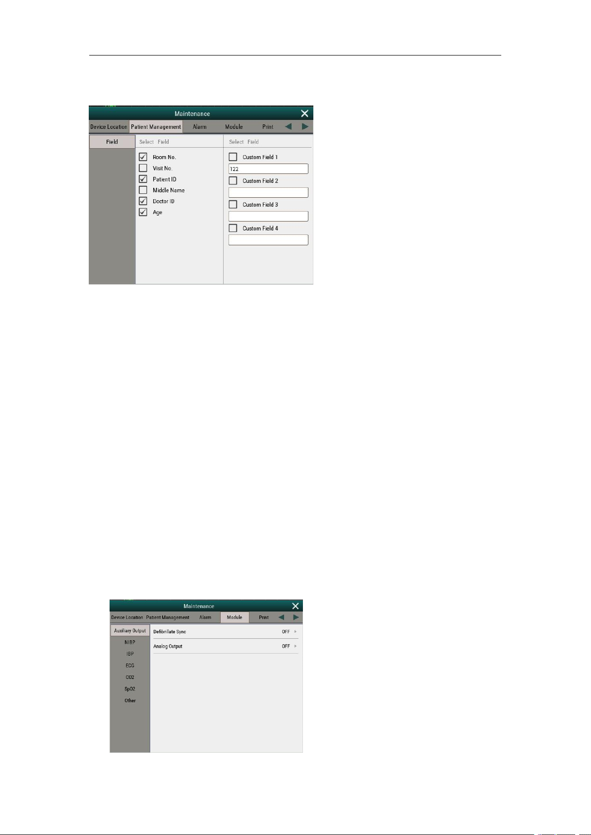
Set the field:
Select the items for the patient field (Room No., Visit No., Patient ID, Middle name, Doctor ID,
Page 25
Service Manual of S10&S12 Patient Monitor
24
Age) to display on the patient info menu.
Custom fields: Users can define their own field, up to 4 types.
3 System alarm setup
1) Sound: sent the type of the sound and the alarm internal;
2) Pause/Reset: set alarm pause duration and alarm off reminder (interval);
3) Latching: set different level alarm to visible or audible;
4) Nurse Call: set the alarm type for the nurse call function;
5) Remote View: Set remote bed’s alarms;
6) Other:set alarm delay, intubation duration, alarm level;
7) Note: This menu has been set in factory, do not change the settings without special
requirements
4 Module
1) Auxiliary: Enable or disable Defibrillate Sycn. and Analog Output function ;
2) NIBP: for NIBP testing (Over pressure Test, Static pressure test, Pressure calibration), for
NIBP maintenanve.
3) ECG: set ECG filter user mode, ECG standard, QTc formula or enable ECG gain 0.125;
ECG calibrate is not available for user.
4) CO2: Set the CO2 sensor type, set Atm. Pressure, and CO2 calibration.
5) SpO2: enable or disable function “Use Soft Algorithm, Low confidence Display ? ”
6) Other: Set NIBP or C.O. Invalid Time
Page 26
Service Manual of S10&S12 Patient Monitor
25
5 Ptint
1) Active Grid print
2) Set the network printer service IP (network printer function is not available).
6 Unit
Set the unit for Height, Pressure and Weight
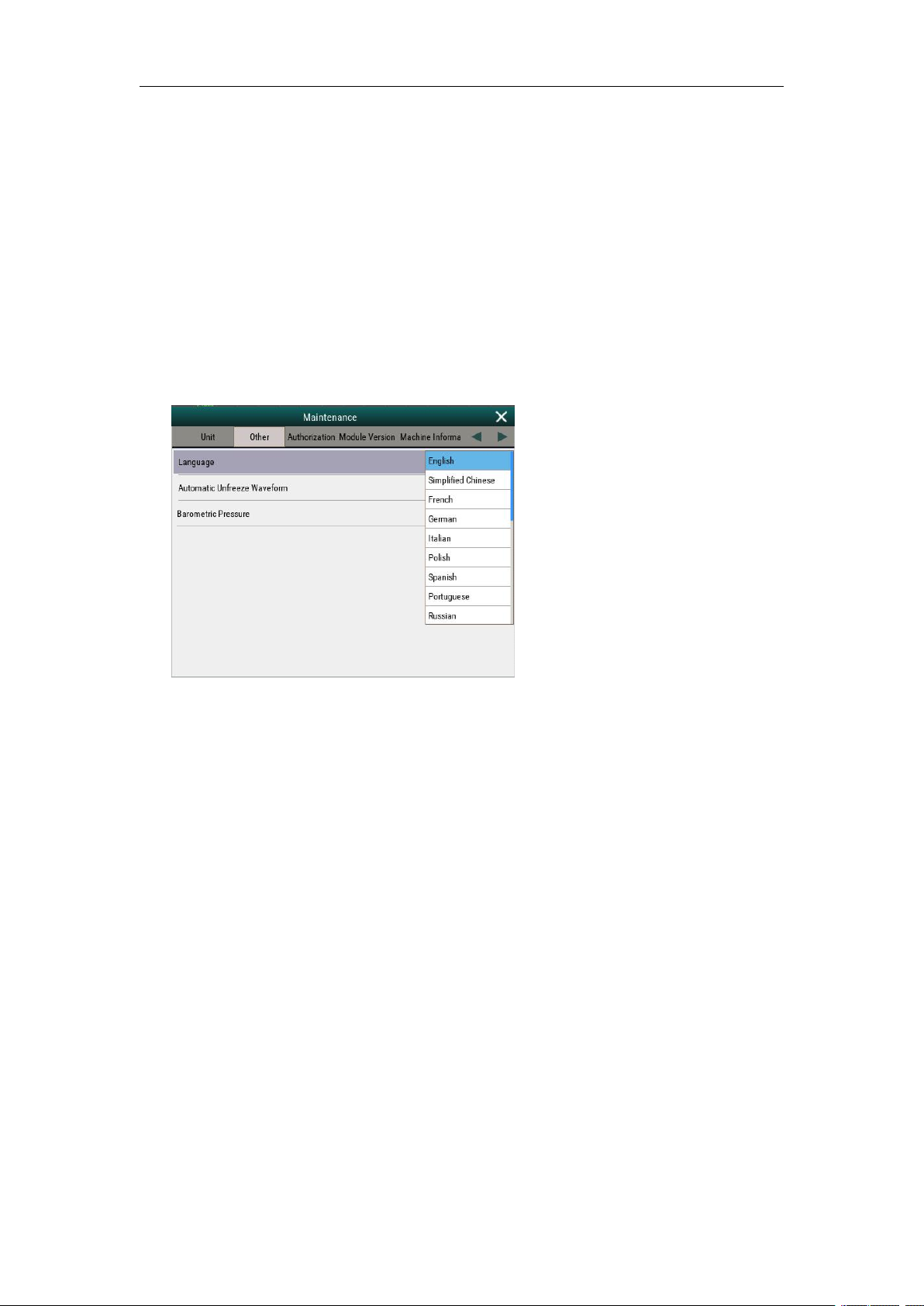
7 Other
1) Select different language menu (22 types)
2) Set the time of Automatic Freeze Waveform
3) Set the Barometric Pressure
8 Authorization
1) Set the Retention time
2) Set the password for alarm setup
3) Set the password for configuration setup
9 Module version
Check the hardware and software of every parameter
10 Machine Information
1) Check the battery voltage
2) Check the touch screen information
3) Statistics : only for R&D testing
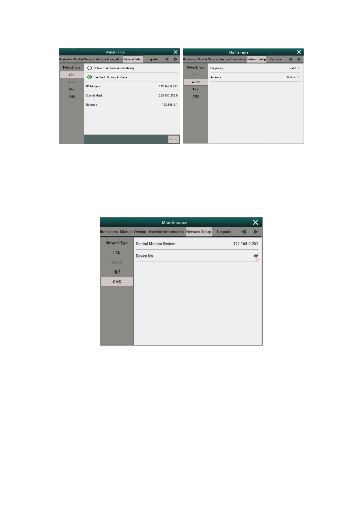
11 Network setup
1) Network type : set the network type of the monitor to LAN or WLAN
2) LAN: Set the IP address of the monitor if the monitor need to connect to the central
monitoring system with network cable. (Pic. LAN)
Page 27
Service Manual of S10&S12 Patient Monitor
26
Pic LAN Pic WLAN
3) WLAN: Set the frequency of the wifi module, and set the type of the wifi module to
external or built-in. This menu is for the wifi central monitoring system. (Pic. WLAN)
4) HL7: if monitor connects to HIS, then can set the data that send to the HIS. For the setting
details, please contact to manufacturer directly.
5) CMS: if monitor connect to central monitoring system, then can set the the IP address of
the CMS, and the device no. of the monitor.
12 Upgrade
Enter this menu to upgrade the opening logo of the monitor.(refer to 4.3 software upgrade)
4.2 NIBP maintenance
4.2.1 NIBP leakage test
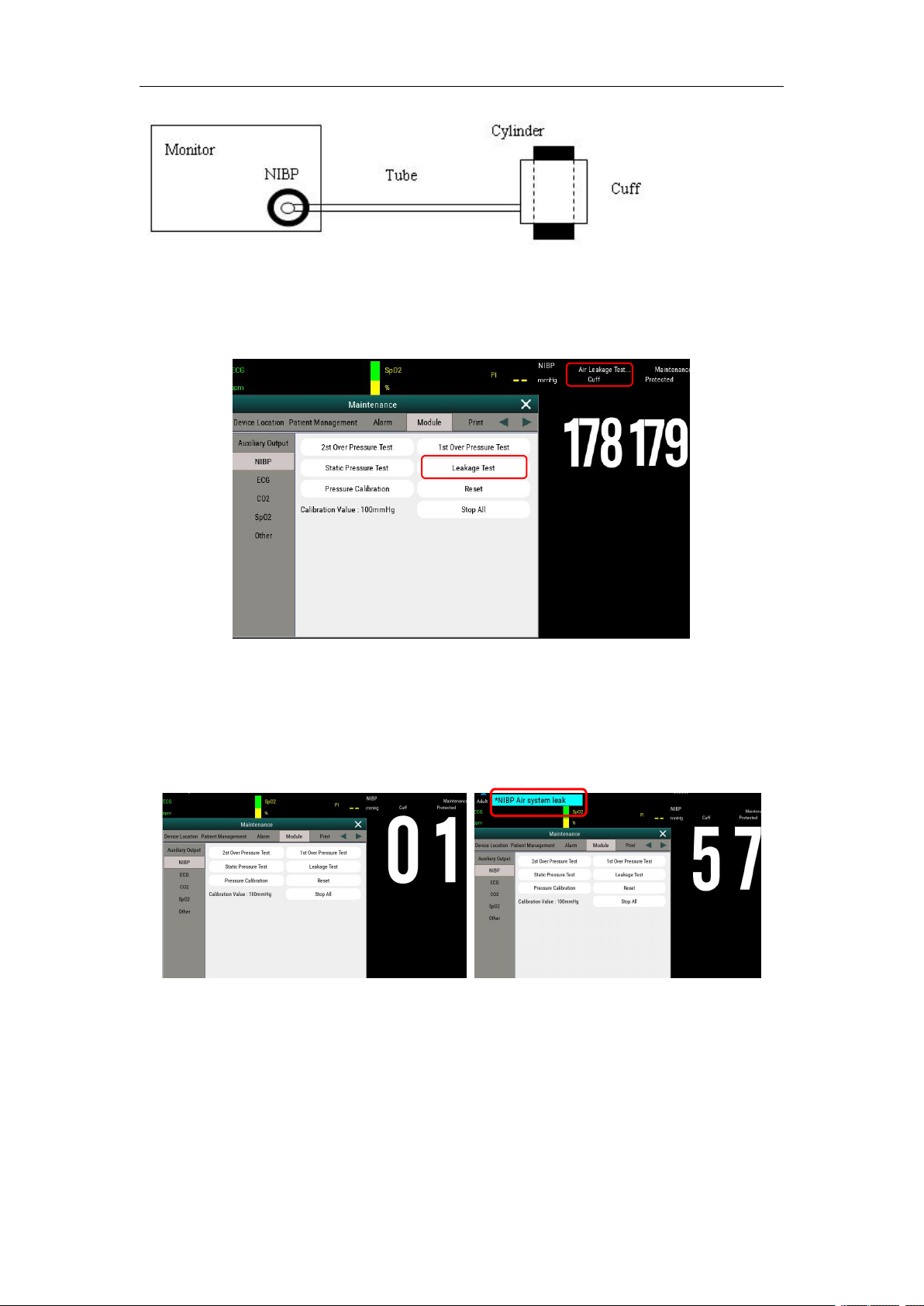
1. Plug the air pipe plug of cuff into the connector (NIBP) of monitor until the plug and socket
contact well
2. Tie the cuff to a metal cylinder.
Page 28
Service Manual of S10&S12 Patient Monitor
27
3,Select【Maintenance】→input password→【Module】→【NIBP】→【leakage Test】,Then the
prompt “Air Leakage Test” will appear on the NIBP parameter area indicating that the system has
started performing Air Leakage test.
The system will automatically inflate the pneumatic system to about 180mmHg.
5. After 20 seconds or so, the system will automatically open the deflating valve, which marks the
completion of an air leakage test.
6. If no error information displays on NIBP parameter area, it indicates that the airway is in good
situation and no air leaks exist. However if the prompt “AIR SYSTEM LEAK” appears in the
place, it indicates that the airway may have air leaks. In this case, the user should check for loose
connection. After confirming secure connections, the user should re-perform the air leakage test.
Normal screen without error information screen with message “Air System leak”
7. Press the stop key to stop air leakage test, leakage test compete.
4.2.2 NIBP calibration
Procedure :
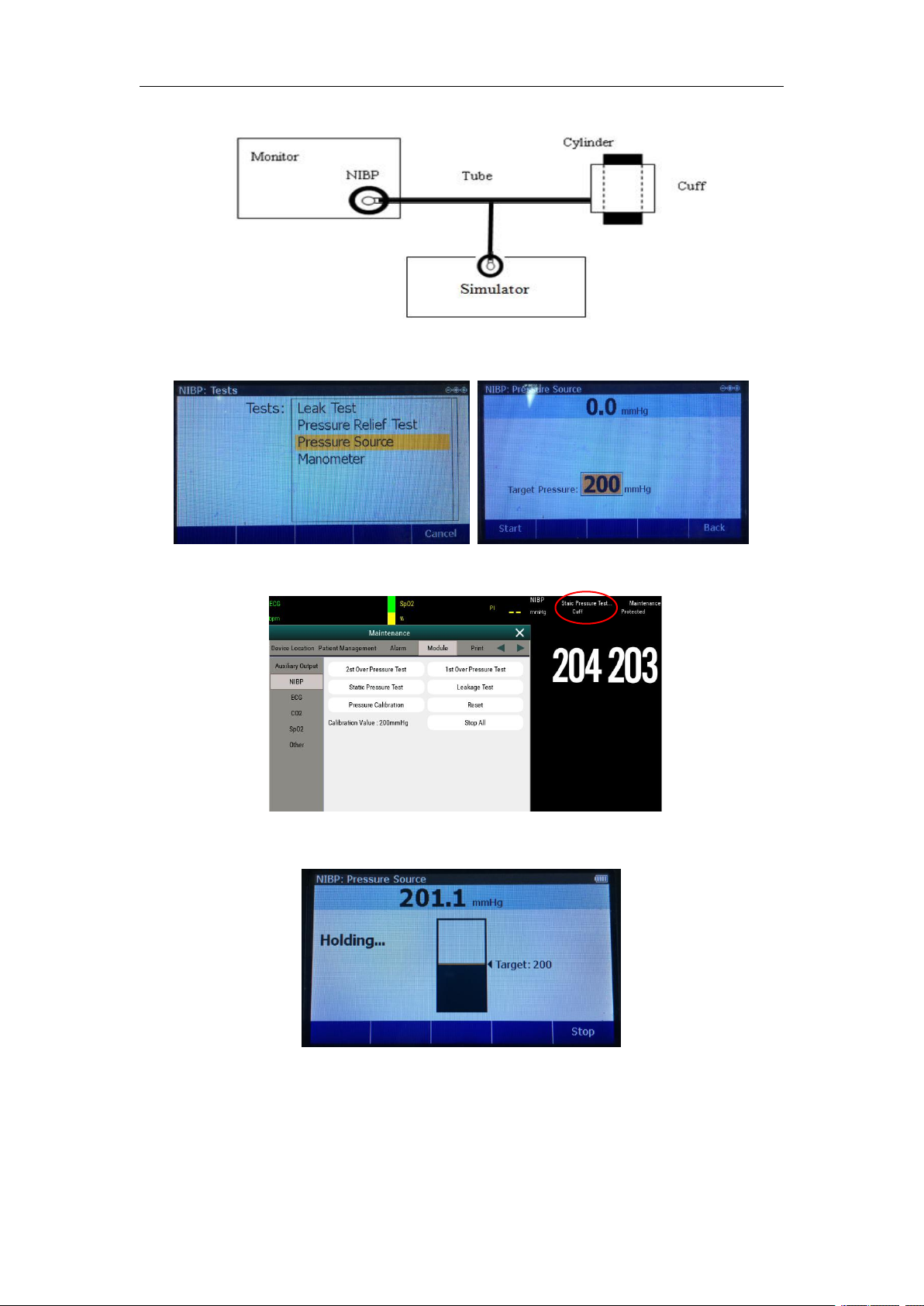
1) Connect the NIBP tube to the cuff, and then the cuff to a metal cylinder, connect the other side
of the NIBP tube, monitor and simulator with a 3-way tube.
Page 29
Service Manual of S10&S12 Patient Monitor
28
2) Setting the simulator: enter menu 【NIBP】→【Test】→【Pressure Source】,then set the value
to 200mmHg;
3) Enter menu : 【Module】→【NIBP】, then press menu【Static Pressure Test】
4) Start the simulator and the monitor to test, check the pressure values showed by monitor and
simulator;
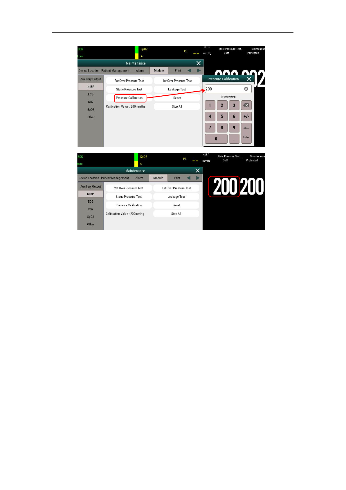
5) Check the pressures, if the gap is over 3 mmHg, enter menu 【Pressure Calibration】, and
input the value 200 mmHg, then “Enter” and exit the menu to save the setting.
Page 30
Service Manual of S10&S12 Patient Monitor
29
6) Repeater step 3 and step 4, check if the pressure showed by monitor and simulator in a same
value or less than 3mmHg, then calibration complete.
4.3 Software Upgrade
Software of this monitor can be upgraded by USB stick.
Caution:
Please confirm the device was connected to the AC power before the upgrading, confirm
the inside battery was full charged. The device out of power may leading the device unable to
starting when at the upgraded process, then must send back to factory for maintain.
1. Main program upgrade:
1) Copy the main program software to a USB stick. Attention: file name cannot be changed in
anyway.
2) Switch on the monitor, and then plug the USB stick into the the monitor.
3) After plug in the USB stick, the monitor will automatically read the info of the USB stick and
the monitor will automatically upgrade the software after 10 second or press the upgrade button to
upgrade software directly.
Page 31

Service Manual of S10&S12 Patient Monitor
30
4) When the monitor’s screen displays “Upgrade successful”, then press the reboot button and
unplug the USB stick, and then restart the monitor.
5) Software upgrade complete.
2. Change the opening Logo of the Monitor
1. Rename the logo software to logo.bin;
2. Copy the logo software to a USB Stick;
3. Plug in the USB disk to the monitor, and then witch on the monitor, and enter the upgrade menu:
【main】→【maintenance】→【Upgrade】→【logo】, then the monitor will upgrade automatically.
4. The monitor will reboot automatically when upgrade complete.
Note: Need to rename the logo software to “logo.bin”.
Page 32

Service Manual of S10&S12 Patient Monitor
31
Phenomenon
Possible reason
Trouble-shooting
Monitor can be
turned on, but
LED or battery
LED does not
light up
AC power is not
connected, or battery
capacity is insufficient
Check whether the AC power is connected
correctly, or whether the battery capacity is
sufficient.
Cable failure
1. Check whether the power switch and the
cable from the indicator to the key board, the
cable from key board to the main control unit
and the cable from the power module to the
main control unit are properly connected.
2. Check whether the cables and plugs are
damaged.
Power module is
damaged
Replace the power module.
Battery cannot be
recharged
Power module is
damaged
Replace the power module.
Battery failure
Replace the battery.
Blank screen,
monitor runs
normally
Cable failure
1. Check whether the cable from the LCD
display screen to the main-board is properly
connected.
2. Check whether cables and connectors are
damaged.
Main board is damaged
Replace the backlight board.
LCD display screen
is damaged
Replace the LCD display screen.
Touch screen has
no response
Cable failure
Check whether the cable of the touch screen are
properly connected.
Check if the cable damaged.
Re-connect the cable of replace a new touch
screen.
Chapter 5 Troubleshooting
5.1 Overview
This chapter conducts categorization based on the failure type of the monitor, and for
troubleshooting, please refer to the failure table and conduct checks according to the sequence.
The recommended solutions given in this chapter can solve most of the equipment failures, but
may not necessarily cover all possible failures. In case of any failures not included in this chapter,
please contact the after-sale service department of our Company.
5.2 Common Failure Analysis and Trouble-shooting
Page 33

Service Manual of S10&S12 Patient Monitor
32
Screen failure
Check if the screen is damaged.
Note: if replacing the touch screen, need to replace the whole set together
with the front case.
Recorder is unable
to print
Recorder function is
disable
1. Check whether the recorder indicator lights
up.
2. If the indicator lights up, active the function
of the recorder in the menu of 【 Factory
Maintenance】. If the indicator does not light up,
it indicates that there are other failures.
Printing paper is
mounted reversely
Install the printing paper again.
Cable failure
1. Check whether the cable from the
recorder to the main-board is properly
connected.
2. Check whether cables and plugs are damaged.
Recorder failure
Replace the recorder.
USB equipment
can not be used
(peripheral
equipment has no
damage)
USB interface board is
damaged
Replace the USB interface board.
Main-board is damaged
Replace the main-board.
Page 34
33
Chapter 6 Maintenance and Disassembling
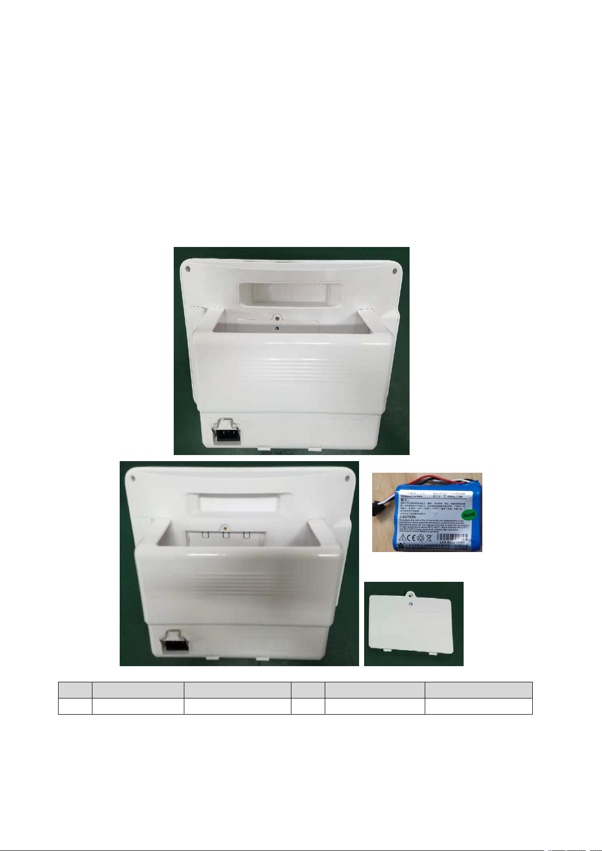
No.
Item
Material code
No.
Item
Material code
1
Lithium battery
1.12.06-11-5000-00
2
Battery cover plate
1.19.02-000044-0-1
①
②
6.1 Tool
During the process of disassembling and replacing the parts, you may need to use the following tools:
1. Cross screwdriver 2. Slotted screwdriver 3. Sharp-nose plier
6.2 Disassemble Procedure
Note: Before disassembling the monitor, please unplug the power code and remove the battery from the
monitor.
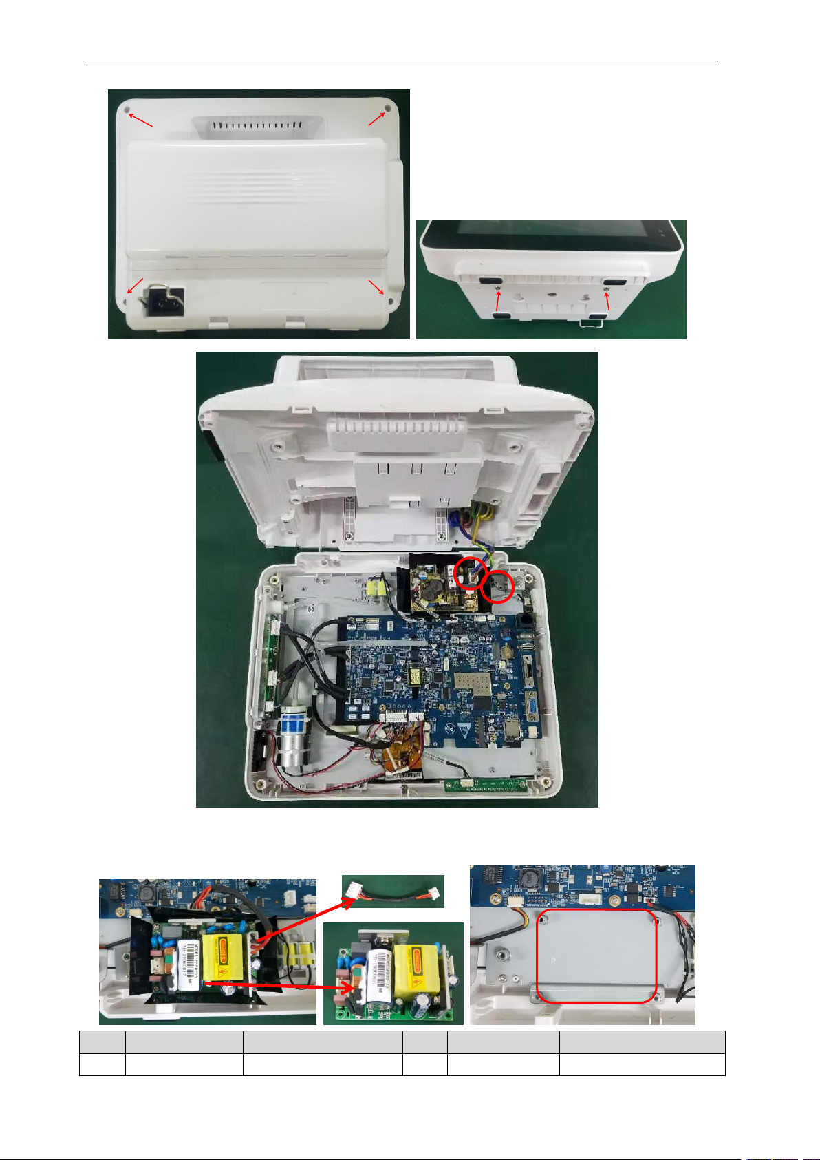
1. Remove the screws that fix the front panel, then unplug the cables and separate the front panel from the
monitors.
Page 35
Service Manual of S10&S12 Patient Monitor
34
No.
Item
Material code
No.
Item
Material code
1
SMPS wire
1.11.59-0000009-01
2
SMPS
1.15.01-0064-01-00
②
①
2. Unplug the cable that connect to the power supply board, then remove the screws, and then take out the
power supply board;
Page 36
Service Manual of S10&S12 Patient Monitor
35
No.
Item
Material code
No.
Item
Material code
1
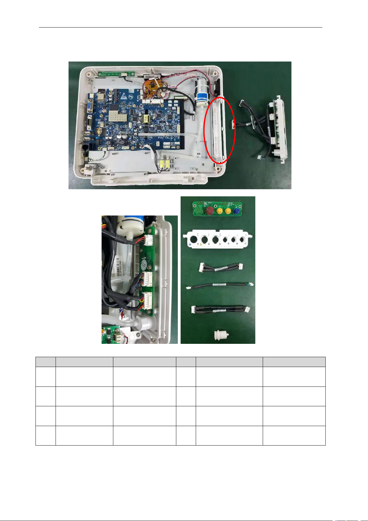
Connector panel A
2.02.0001-02-00
2
S12 connector fixing
plate
1.19.02-000052-0-1
3
TEMP & SpO2
connector wire
1.11.59-0000005-01
6
NIBP connector
1.19.02-000013-0-1,
1.19.02-000014-0-1
4
DM module
connecting wire
1.11.59-0000025-01
5
ECG connector wire
1.11.59-0000004-01
1-2
Connector PCB B
2.02.0001-03-00
2-2
S10 Connector fixing
plate
1.19.02-000042-0-1
①
②
③
④
④
⑤
⑥
3. Remove the cables and screws, and then take out the connector panel set;
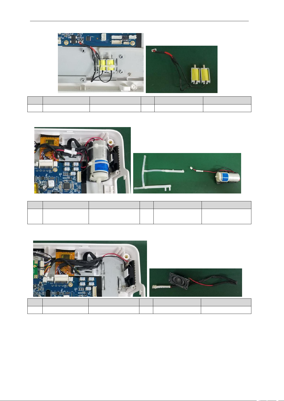
4. Remove the cable and cut the cable tie, then take out the valves;
Page 37
Service Manual of S10&S12 Patient Monitor
36
No.
Item
Material code
No.
Item
Material code
1
Valves set
1.15.20-0009-03-00
No.
Item
Material code
No.
Item
Material code
1
PVC tube
1.15.00-0033-01-00,
1.15.00-0033-02-00
2
NIBP pump
2.02.0001-20-00
No.
Item
Material code
No.
Item
Material code
1
speaker
1.16.21-000018-010
Speaker wire
1.11.29-0000008-01
①
①
②
①
②
5. Remove the cable and cut the cable tie, then take out the pump;
6. Remove the cable and then take out the speaker;
7. Remove the cable and screws, and then take out the alarm-light board;
Page 38

Service Manual of S10&S12 Patient Monitor
37
No.
Item
Material code
No.
Item
Material code
1
Alarm-light wire
1.11.59-0000001-01
2
Alarm-light PCB
2.02.0001-04-00
No.
Item
Material code
No.
Item
Material code
1
Main board (basic)
2.02.0001-01-05
2
Main board (wifi)
2.02.0001-01-08
3
Main board (VGA/Analog Output/Dysn/Nurse Call)
2.02.0001-01-10
4
Main board (VGA/Analog Output/Dysn/Nurse Call+wifi)
2.02.0001-01-13
5
Main board (VGA/Analog Output/Dysn/Nurse Call+wifi+ 12 leads)
2.02.0001-01-00
①
②
8. Remove the cables with connect to the mainboard, then release the screws that fix the mainboard, then
take out the main board;
Note: Depends on different configuration of the monitors, there are different types of
main boards.
Page 39
Service Manual of S10&S12 Patient Monitor
38
No.
Item
Material code
No.
Item
Material code
1
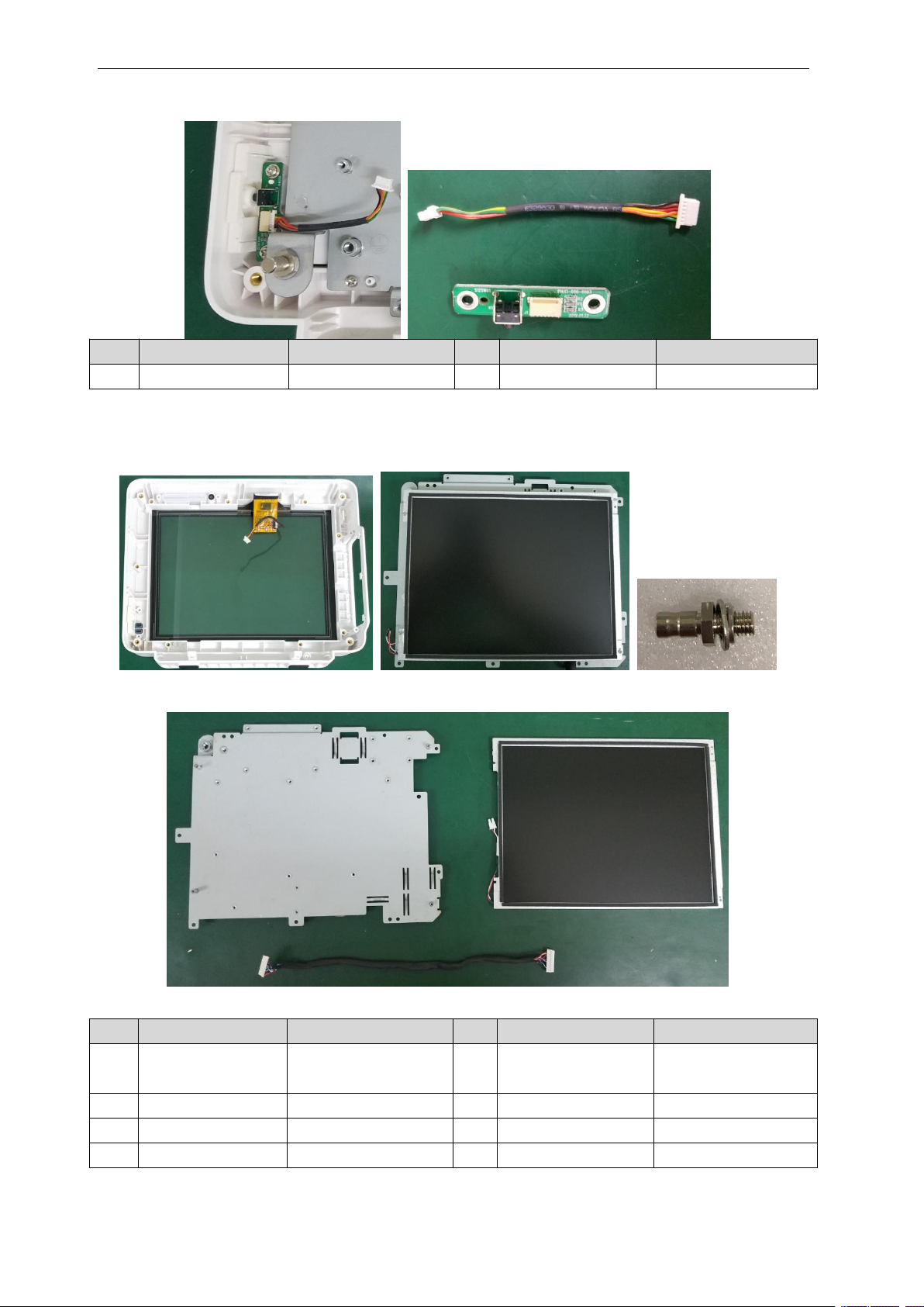
Power switch wire
1.11.59-0000002-01
2
Power switch PCB
2.02.0001-05-00
No.
Item
Material code
No.
Item
Material code
1
LCD mounting
plate
1.20.02-000004-0-1
2
10.4’ LCD
1.14.104-1704-01-1
3
LCD cable
1.11.59-0000015-01
4
10.4’ touch screen
1.14.104-0012-00-1
5
S10 Front case
1.19.02-000040-0-1
6
Touch screen wire
1.11.59-0000000-01
7
Grounding role
1.21.14-000005-005
①②②
⑥
⑤
③
①
⑦
④
9. Remove the cable and screws, and then take out the power switch board;
10. Remove the screws and unplug the LCD cable and backlight cable, and then take out the LCD panel;
11. Remove the screws, and then separate the LCD from the mounting plate;
10.4’ front panel:
12.1’ front panel
Page 40
Service Manual of S10&S12 Patient Monitor
39
No.
Item
Material code
No.
Item
Material code
1
LCD mounting
plate
1.20.02-000003-0-1
2
12.1’ LCD
1.14.121-0006-01-1
3
LCD cable
1.11.59-0000020-01
4
12.1’ Touch screen
1.14.104-0012-01-1
5
S12 Front case
1.19.02-000050-0-1
6
Touch screen wire
1.11.59-0000021-01
7
Grounding role
1.21.14-000005-005
8
Backlight wire
1.11.59-0000021-01
No.
Item
Material code
No.
Item
Material code
1
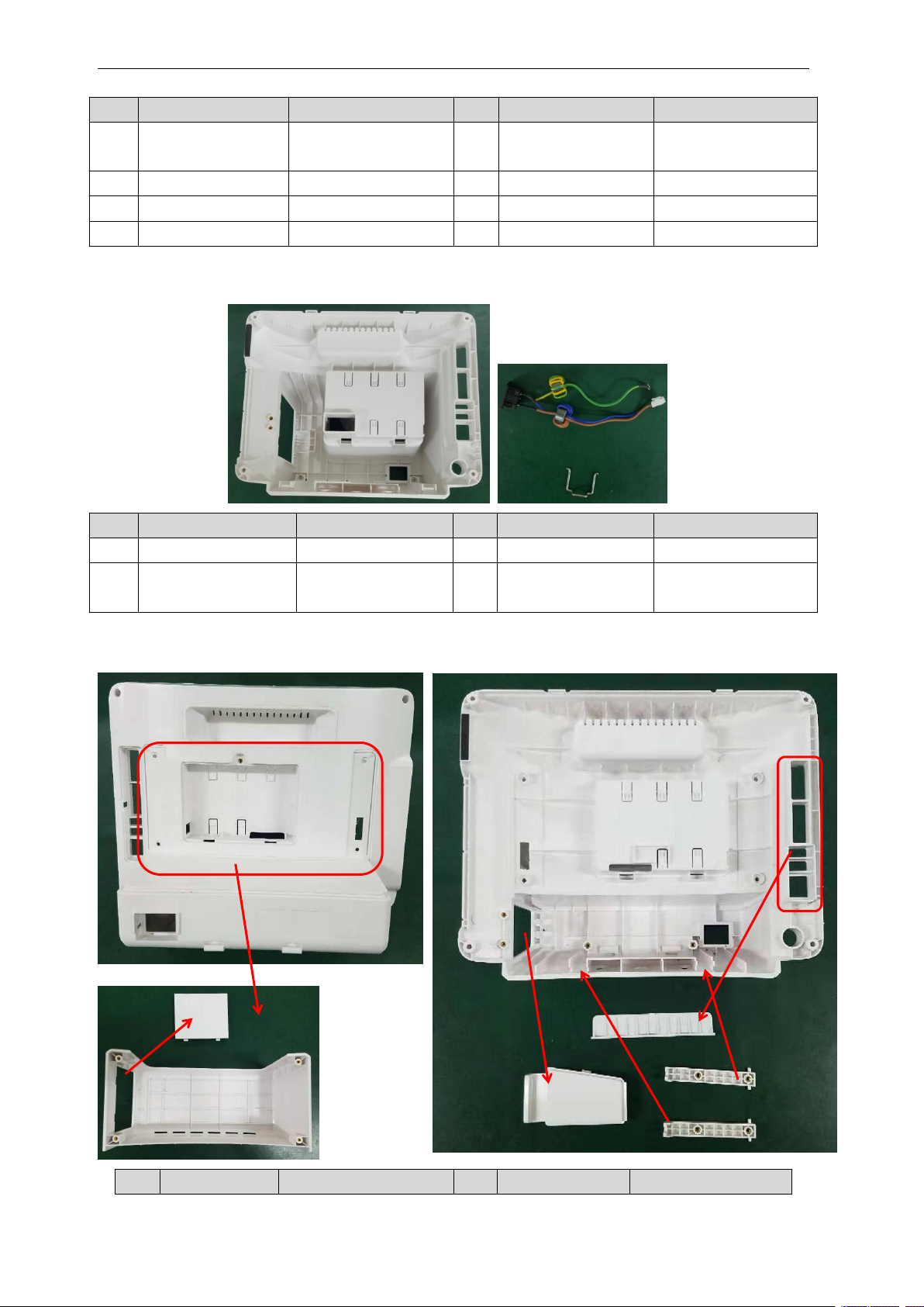
AC connector
1.10.00-0033-00-02
2
grounding wire
1.11.59-0000008-01
3
3PVH AC wire &
1.11.59-0000012-01
4
Power code fixing
bracket
1.20.02-000002-0-1
No.
Item
Material code
No.
Item
Material code
④
③
②
①
①
②
③
④
⑤
⑥
12. Remove the AC socket and the power code fixing bracket form the rear case.
13. Disassembling the rear case.
Page 41

40
1
S12 rear case
1.19.02-000060-0-1
1
S10rear case
1.19.02-000030-0-1
2
S12
accessories slot
1.19.02-000061-0-1
2
S10 accessories
slot
1.19.02-000031-0-1
3
Recorder cover
plate
1.19.02-000015-0-1
4
S12connector
cover plate
1.19.02-000057-0-1
5
Fixing plate
1.19.02-000010-0-1
6
Interface cover
plate
1.19.02-000011-0-1
Main board interfaces
pump
Power switch
ECG
Connector
panel A/B
SpO2&TEMP
DM
Speaker
Alarm
lamp
12.1 LCD
backlight
J14
J34
J33
J20
J8
J25
J23
J24
J21
Printer
J27
LCD
J26
valves
SMPS
J1
J11
Touch screen
10.4’ LCD
backlight
J15
Connector
panel C
Battery
VGA
USB
RJ45
SCSI
Service Manual of S10&S12 Patient Monitor
Page 42
41
Appendix
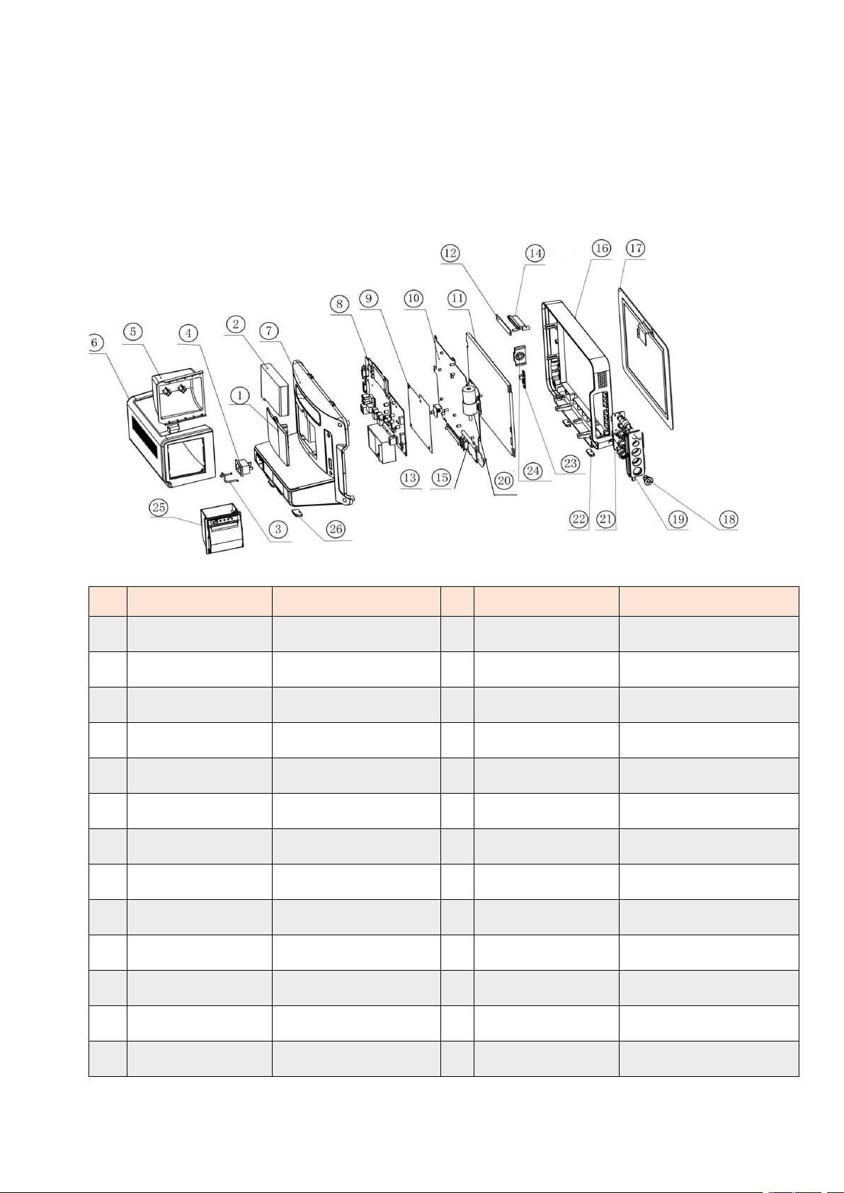
No.
Material code
Material Name
No.
Material code
Material Name
1
1.19.02-000044-0-1
battery cover plate
2
1.12.06-11-5000-00
Lithium battery (11.1V/2.5Ah)
3
1.20.02-000002-0-1
power code fixing bracket
4
1.10.00-0033-00-02
power socket
5
1.20.02-000001-0-1
recorder mounting plate
6
1.19.02-000043-0-1
rear cover plate
7
1.19.02-000041-0-1
rear case
8
2.02.0001-01-05
mainboard(basic)
9
1.19.02-000027-1-1
mainboard insulation sheet
10
1.20.02-000004-0-1
LCD mounting plate
11
1.14.104-1704-01-1
10.4' LCD
12
2.02.0001-04-00
alarm lamp board
13
1.15.01-0064-01-00
power supply board
14
1.19.02-000022-0-1
light guide
15
1.15.20-0009-03-00
valves
16
1.19.02-000040-0-1
front case
17
1.14.104-0012-00-1
10.4' touch screen
18
1.19.02-000013-0-1
NIBP connector
19
1.19.02-000042-0-1
connector cover plate
20
2.02.0001-20-00
pump
21
2.02.0001-03-00
connector panel B
22
1.19.02-000026-0-1
rubber pad (front case)
23
2.02.0001-05-00
power switch board
24
1.19.02-000021-0-1
keypad
25
2.00.0059-11-10
recorder
26
1.19.02-000026-1-1
rubber pad (rear case)
S10 Exploded view
Part list
Page 43
42
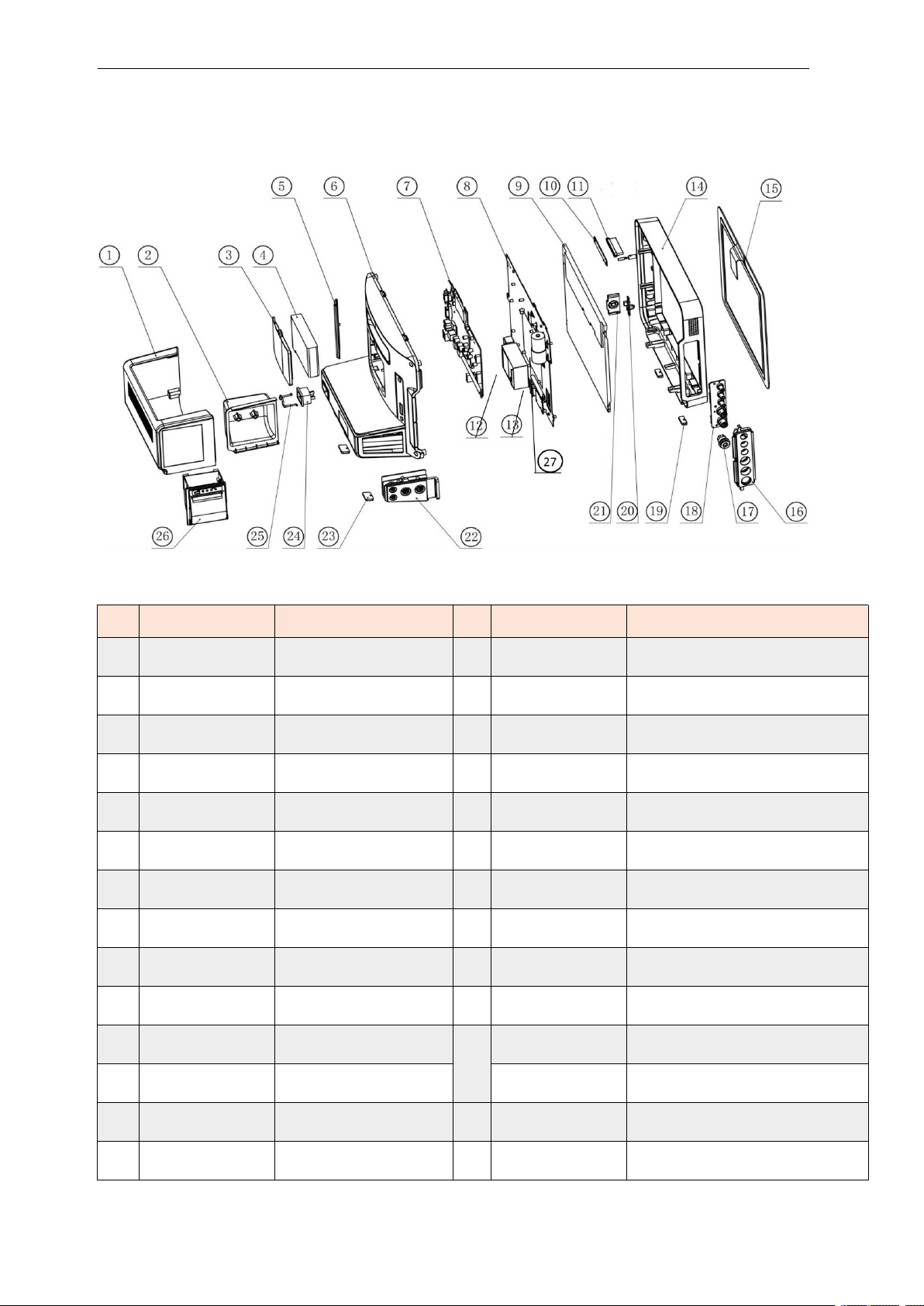
S12 Exploded view
No.
Material code
Material Name
No.
Material code
Material Name
1
1.19.02-000043-0-1
rear cover plate
2
1.20.02-000001-0-1
recorder mounting plate
3
1.19.02-000044-0-1
battery cover plate
4
1.12.06-11-5000-00
Lithium battery (11.1V/2500mAH)
5
1.19.02-000011-0-1
interface cover plate
6
1.19.02-000041-0-1
rear case
7
2.02.0001-01-05
mainboard(basic)
8
1.20.02-000004-0-1
LCD mounting plate
9
1.14.104-1704-01-1
10.4' LCD
10
2.02.0001-04-00
alarm lamp board
11
1.19.02-000022-0-1
light guide
12
1.15.01-0064-01-00
power supply board
13
1.15.20-0009-03-00
valves
14
1.19.02-000040-0-1
front case
15
1.14.104-0012-00-1
10.4' touch screen
16
1.19.02-000042-0-1
connector cover plate
17
1.19.02-000013-0-1
NIBP connector
18
2.02.0001-02-00
connector panel A
19
1.19.02-000026-0-1
rubber pad (front case)
20
2.02.0001-05-00
power switch board
21
1.19.02-000021-0-1
keypad
22
2.02.0001-07-00
connector panel C
23
1.19.02-000026-1-1
rubber pad (rear case)
2.02.0001-06-01
optional parameters interface board
24
1.10.00-0033-00-02
power socket
25
1.20.02-000002-0-1
power code fixing bracket
26
2.00.0059-11-10
recorder
27
2.02.0001-20-00
pump
Service Manual of S10&S12 Patient Monitor
Part List
Page 44

Service Manual of S10&S12 Patient Monitor
43
Product Model: S10/S12 Patient monitor
Product Name: Patient monitor
Manufacturer Name: Guangdong Biolight Meditech Co,.Ltd.
Address: No.2 Innovation First Road, Technical Innovation Coast, Hi-tech Zone, Zhuhai,
P.R.China
Post code: 519085
Page 45

44
PN: 22-048-0008
Service Manual of S10&S12 Patient Monitor
 Loading...