

Page 1

X4100/200/300
Einbauanleitung
Erweiterungs- und Ressourcenkarten
Installation Guide
Expansion Cards and Resource Cards
Copyright© 2003 BinTec Access Networks GmbH, alle Rechte vorbehalten
Version 1.0
Dokument #75111M
Februar 2003
X4100/200/300 Einbau / Installation 1
Page 2

2 BinTec Access Networks GmbH
Page 3

Inhaltsverzeichnis
Inhaltsverzeichnis
1 Willkommen 5
1.1 Lieferumfang 5
1.2 Benötigtes Werkzeug 6
2 Installation der Erweiterungskarte
und Ressourcenkarte(n) 7
2.1 Blindabdeckung abnehmen oder
Erweiterungskarte ausbauen 7
2.2 Erweiterungskarte mit Ressourcenkarte(n) ausstatten 9
2.2.1 ISDN-BRI-Erweiterungskarte 10
2.2.2 ISDN-PRI-Erweiterungskarte /
G.703-Erweiterungskarte 14
2.2.3 LAN-Erweiterungskarte 15
2.3 Erweiterungskarte einbauen 18
3 Wiederinbetriebnahme 19
X4100/200/300 Einbau / Installation 3
Page 4

Table of Contents
Table of Contents
1 Welcome 21
1.1 Scope of Supply 21
1.2 Tool Required 22
2 Installation of the Expansion Card
and Resource Card(s) 23
2.1 Remove Dummy Cover or Expansion Card 23
2.2 Equipping an Expansion Card with a
Resource Card(s) 25
2.2.1 ISDN BRI Expansion Card 26
2.2.2 ISDN-PRI Expansion Card /
G.703 Expansion Card 30
2.2.3 LAN Expansion Card 31
2.3 Installing the Expansion Card 33
3 Beginning Operation 35
4 BinTec Access Networks GmbH
Page 5

Lieferumfang
1
1 Willkommen
Sie haben eine Erweiterungskarte und/oder Ressourcenkarte(n) zum Einbau in
das X4100/200/300-Grundgerät erworben. Diese Einbauanleitung hilft Ihnen,
Ihren X4100/200/300schnellund einfach damit aufzurüsten. Neben der gesamten Funktionalitätdes X4100/200/300-Grundgeräts stehen Ihnen dannauch die
zusätzlichen Funktionen der jeweiligen Erweiterungskarte und/oder Ressourcenkarte(n) zur Verfügung.
Diese Einbauanleitung gliedert sich in die folgenden Hauptabschnitte:
■ Installation der Erweiterungskarte bzw. Ressourcenkarte(n)
■ Wiederinbetriebnahme und Überprüfung
1.1 Lieferumfang
Der Lieferumfang umfaßt:
■ bei einer WAN-Schnittstellenkarte für ISDN-BRI (X4E-2/3BRI):
– Erweiterungskarte (verpackt in einer Antistatiktasche)
– 3 ISDN-Kabel
– 2 Abstandsbolzen mit 2 Kreuzschlitzschrauben und 2 Unterlegschei-
ben (wenn nicht vormontiert)
– Einbauanleitung
– gegebenenfalls Lizenzblatt
■ bei einer WAN-Schnittstellenkarte für ISDN-PRI und/oder G.703 (X4E-1/
2PRI):
– Erweiterungskarte (verpackt in einer Antistatiktasche)
– 4 Abstandsbolzen mit 4 Kreuzschlitzschrauben und 4 Unterlegschei-
ben (wenn nicht vormontiert)
– Einbauanleitung
– gegebenenfalls Lizenzblatt
X4100/200/300 Einbau 5
Page 6

1
Willkommen
■ bei einer LAN-Schnittstellenkarte für 10/100 MBit/s (X4E-2FE):
– Erweiterungskarte (verpackt in einer Antistatiktasche)
– Einbauanleitung
■ bei einer Ressourcenkarte mit Digitalmodems (XT-Q, XT-S, XT-M, XT-2M
oder XT-L):
– Ressourcenkarte (verpackt in einer Antistatiktasche)
– Einbauanleitung
– 2 Kreuzschlitzschrauben und 2 Unterlegscheiben (wenn Abstandsbol-
zen nicht vormontiert)
■ bei einer Ressourcenkarte zur Verschlüsselung und Kompression (XT-
ENC):
– Ressourcenkarte (verpackt in einer Antistatiktasche)
– Einbauanleitung
■ bei einer Ressourcenkarte zur schnelleren Erzeugung der Verschlüsse-
lungs-Keys (XT-VPN):
– Ressourcenkarte (verpackt in einer Antistatiktasche)
– Einbauanleitung
1.2 Benötigtes Werkzeug
Zur Montage einer Erweiterungskarte bzw. Ressourcenkarte benötigen Sie einen Kreuzschlitzschraubendreher zum Abnehmen der Blindabdeckung und
zum Montieren der Erweiterungskarte sowie der Ressourcenkarte(n) mit Digitalmodems.
6 X4100/200/300 Einbau
Page 7

Blindabdeckung abnehmen oder Erweiterungskarte ausbauen
2
2 Installation der Erweiterungskarte
und Ressourcenkarte(n)
Achtung!
Elektrostatische Aufladung kann elektronische Bauteile schädigen. Um die Schädigung von Bauteilen zu vermeiden, beachten
Sie bitte folgende Vorsichtsmaßnahmen:
➤ Erden Sie sich, bevor Sie die Erweiterungskarte bzw. Res-
sourcenkarte auspacken und bevor Sie Installationsarbeiten
am Gerät durchführen.
➤ BerührenSie Platinen immernur an denRändern, und fassen
Sie nicht auf Leitungen oder Bauteile.
2.1 Blindabdeckung abnehmen oder Erweiterungskarte ausbauen
Zunächst müssen Sie die Blindabdeckung des Erweiterungssteckplatzes des
X4100/200/300-Grundgeräts abnehmen bzw. eine bereits eingebaute Erweite-
rungskarte ausbauen.
Gefahr!
Fassen Sie beim Einbau oder Austausch der Erweiterungskarte
nicht in den Erweiterungssteckplatz. Es besteht Lebensgefahr
durch Stromschlag!
➤ Fassen Sie nicht in den Erweiterungssteckplatz von X4100/
200/300!
X4100/200/300 Einbau 7
Page 8

2
Installation der Erweiterungskarte und Ressourcenkarte(n)
Achtung!
Der Einbau oder Austausch einerErweiterungskarte darf nichtim
laufenden Betrieb durchgeführt werden. X4100/200/300 muß auf
jeden Fall von der Stromversorgung getrennt werden, sonst besteht die Gefahr, daß sowohl X4100/200/300 als auch die Erweiterungskarte zerstört werden.
Falls Sie dennoch die Installation einer Erweiterungskarte bei laufendem Betrieb durchführen, erlischt die Garantie!
➤ Ziehen Sie immer den Netzstecker von X4100/200/300, be-
vor Sie die Erweiterungskarte einstecken oder austauschen.
➤ Schließen Sie X4100/200/300 erst an die Stromversorgung
an, nachdem das Gerät komplett installiert ist und Sie die Installation noch mal geprüft haben.
Gehen Sie folgendermaßen vor:
➤ Ziehen Sie den Netzstecker von X4100/200/300.
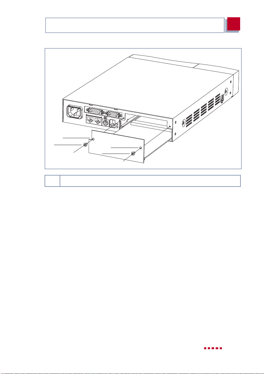
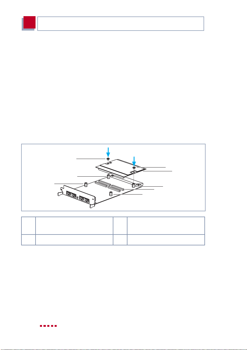
➤ Lösen Sie die Schrauben der Blindabdeckung oder der eingebauten Erwei-
terungskarte (siehe Bild 2-1, Seite 9).
➤ Nehmen Sie die Blindabdeckung ab bzw. ziehen Sie die vorhandene Er-
weiterungskarte heraus.
➤ Behalten Sie die beiden Schrauben der Blindabdeckung für die Befesti-
gung der Erweiterungskarte.
8 X4100/200/300 Einbau
Page 9
Erweiterungskarte mit Ressourcenkarte(n) ausstatten
1
2
1,2 Bohrung und Schraube zum Befestigen der Erweiterungskarte
Bild 2-1: Ein- bzw. Ausbau einer Erweiterungskarte
1
2
2
2.2 Erweiterungskarte mit Ressourcenkarte(n) ausstatten
Wenn Sie Ihre Erweiterungskarte mit Ressourcenkarte(n) ausstatten wollen,
montieren Sie diese im nächsten Schritt. Wenn Sie die Erweiterungskarte ohne
Ressourcenkarte(n) in Betrieb nehmen wollen, fahren Sie fort mit Kapitel 2.3,
Seite 18.
X4100/200/300 Einbau 9
Page 10

2
Installation der Erweiterungskarte und Ressourcenkarte(n)
Achtung!
Der Einbau der PRI/G.703-Erweiterungskarte bzw. der Einbau
von Ressourcenkarten in eine Erweiterungskarte führt zu verstärkter Wärmeentwicklung. Um die Schädigung von Bauteilen zu
vermeiden, ist der Einsatz einer Lüfterkassette zwingend erforderlich!
➤ Setzen Sie bei Verwendung der PRI/G.703-Erweiterungskar-
te oder einer Erweiterungskarte mit Ressourcenkarte(n) im
X4100/200/300-Einbaugerät die Lüfterkassette ein.
Sie können die Lüfterkassette von Ihrem Lieferanten käuflich erwerben.
Folgende Ressourcenkarten sind erhältlich:
■ Ressourcenkarten mit Digitalmodems (XT-Q, XT-S, XT-M, XT-2M und
XT-L) für ISDN-PRI- und ISDN-BRI-Karten.
■ Ressourcenkarte für Verschlüsselung und Kompression (XT-ENC) für
ISDN-BRI- und LAN-Karten.
■ Ressourcenkarte zur schnelleren Erzeugung von Verschlüsselungs-Keys
und für eine höhere Anzahl von VPN-Verbindungen (XT-VPN) für ISDNPRI- und ISDN-BRI-Karten.
2.2.1 ISDN-BRI-Erweiterungskarte
Die ISDN-BRI-Erweiterungskarte können Sie mit einer Ressourcenkarte mit Digitalmodems und/oder mit einer Ressourcenkarte für Verschlüsselung und
Kompression (XT-ENC oder XT-VPN) ausstatten. Montieren Sie zuerst die
Ressourcenkarte für Verschlüsselung und Kompression und anschließend die
Ressourcenkarte mit Digitalmodems, wenn Sie beide Möglichkeiten nutzen
wollen.
10 X4100/200/300 Einbau
Page 11
Erweiterungskarte mit Ressourcenkarte(n) ausstatten
Ressourcenkarte für Verschlüsselung und Kompression
(XT-ENC oder XT-VPN) aufstecken
Gehen Sie folgendermaßen vor:
➤ Nehmen Sie die Ressourcenkarte aus der Antistatiktasche.
2
4
1
1
5
5
5
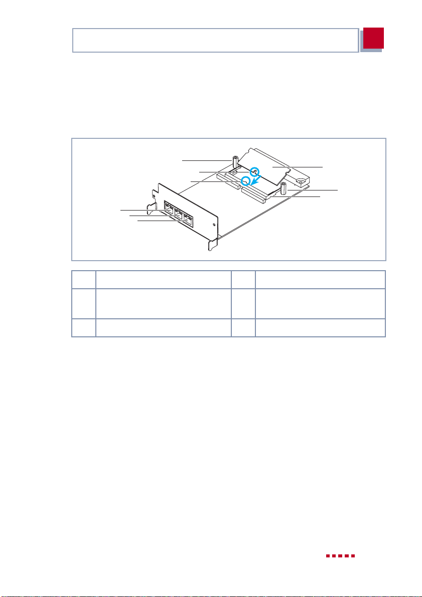
1 Kodierung 4 Abstandsbolzen
2 Ressourcenkarte für Ver-
schlüsselung und Kompression
3 Fassung
Bild 2-2: Ressourcenkarte für Verschlüsselung und Kompression mit BRI-Karte
5 ISDN-BRI-Schnittstellen
2
4
3
➤ Montieren Sie die Abstandsbolzen (falls nichtvormontiert) auf derErweite-
rungskarte (siehe Bild 2-2, Seite 11): Setzen Sie eine Unterlegscheibe auf
die jeweils zugehörige Kreuzschlitzschraube und stecken Sie diese vonunten durch die Erweiterungskarte, und montieren Sie dann den Abstandsbolzen.
➤ Setzen Sie die Ressourcenkarte schräg von oben in diedafür vorgesehene
Fassung. Achten Sie dabei auf die korrekte Orientierung (Kodierung).
X4100/200/300 Einbau 11
Page 12
2
Installation der Erweiterungskarte und Ressourcenkarte(n)
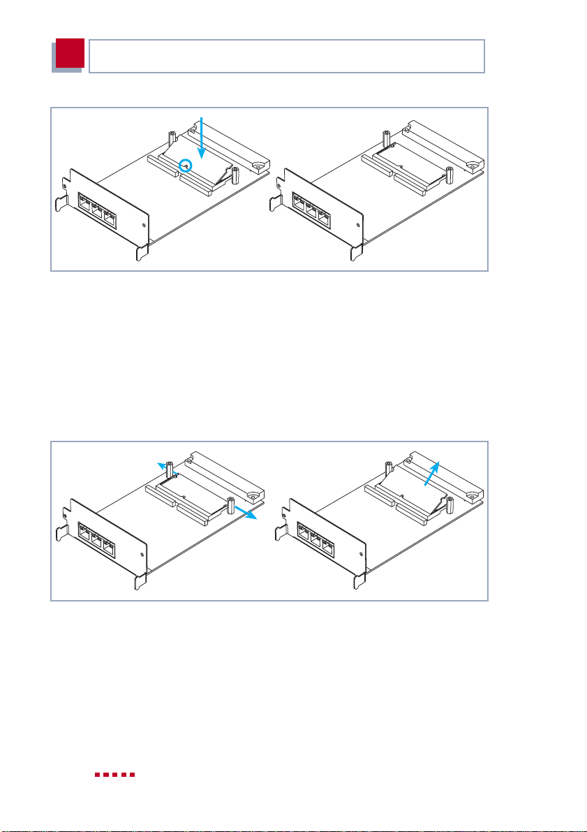
Bild 2-3: Ressourcenkarte für Verschlüsselung und Kompression auf BRI-Karte
➤ Drücken Sie die Ressourcenkarte vorsichtig nach unten, bis sie in die bei-
den seitlichen Laschen einrastet (siehe Bild 2-3, Seite 12).
Ressourcenkarte für Verschlüsselung und Kompression
(XT-ENC oder XT-VPN) abnehmen
Wenn Sie die Ressourcenkarte zur Verschlüsselung und Kompression von der
ISDN-BRI-Erweiterungskarte entfernenwollen, gehen Sie folgendermaßen vor:
Bild 2-4: Ressourcenkarte für Verschlüsselung und Kompression von BRI-Karte
entfernen
➤ Drücken Sie die beiden seitlichen Laschen der Fassung leicht nach außen
(siehe Bild 2-4, Seite 12).
Die Ressourcenkarte richtet sich auf.
➤ Entnehmen Sie die Ressourcenkarte.
12 X4100/200/300 Einbau
Page 13
Erweiterungskarte mit Ressourcenkarte(n) ausstatten
Ressourcenkarte mit Digitalmodems aufstecken
Gehen Sie folgendermaßen vor:
➤ Nehmen Sie die Ressourcenkarte aus der Antistatiktasche.
4
2
5
3
1
6
6
6
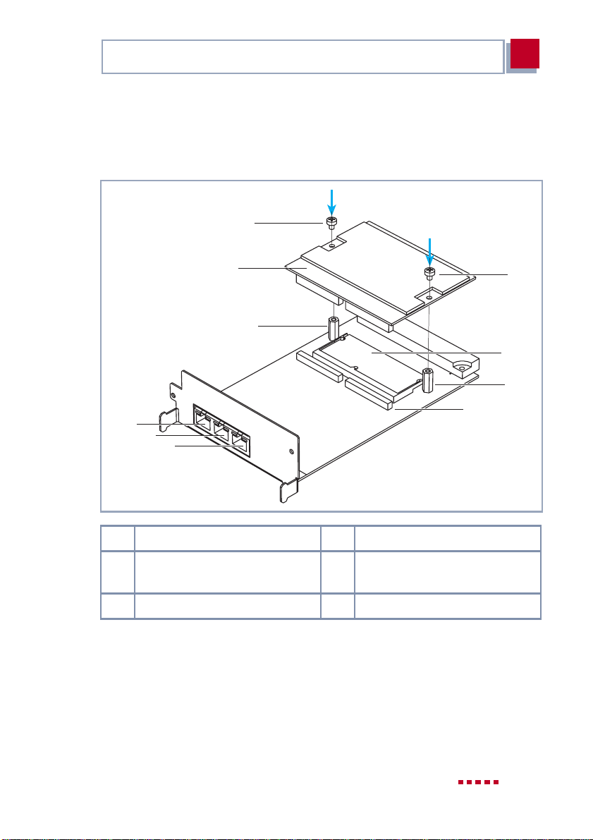
1 Steckverbinder 4 Schrauben
2 Ressourcenkarte für Ver-
schlüsselung (optional)
3 Abstandsbolzen 6 ISDN-BRI-Schnittstellen
Bild 2-5: Ressourcenkarte mit Digitalmodems mit BRI-Karte
5 Ressourcenkarte mit Digital-
modems
4
2
3
➤ Montieren Sie die Abstandsbolzen (falls nichtvormontiert) auf derErweite-
rungskarte (siehe Bild 2-5, Seite 13), falls noch nicht geschehen: Setzen
Sie eine Unterlegscheibe auf die jeweils zugehörige Kreuzschlitzschraube
und stecken Sie diese von unten durch die Erweiterungskarte, und montieren Sie dann den Abstandsbolzen.
X4100/200/300 Einbau 13
Page 14
2
Installation der Erweiterungskarte und Ressourcenkarte(n)
➤ Stecken Sie die Ressourcenkarte von oben auf die Steckverbinder.
➤ Schrauben Sie die Ressourcenkarte mit den im Lieferumfang enthaltenen
Schrauben auf die Abstandsbolzen.
2.2.2 ISDN-PRI-Erweiterungskarte / G.703-Erweiterungskarte
Die ISDN-PRI-Karte kann mit maximal zwei Ressourcenkarten mit Digitalmodems ausgestattet werden.
Gehen Sie folgendermaßen vor:
➤ Nehmen Sie die Ressourcenkarte(n) aus der Antistatiktasche.
4
4
2
2
3
2
1
2
1 Erste Ressourcenkarte mit
Digitalmodems
2 Abstandsbolzen 4 Schrauben
Bild 2-6: Erste Ressourcenkarte mit Digitalmodems mit ISDN-PRI-Karte
3 Steckverbinder für erste Res-
sourcenkarte
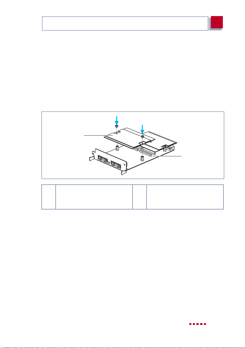
➤ Montieren Sie die Abstandsbolzen (falls nicht vormontiert) auf der
Erweiterungskarte (siehe Bild 2-6, Seite 14): Setzen Sie eine
Unterlegscheibe auf die jeweils zugehörige Kreuzschlitzschraube und
stecken Sie diese von unten durch die Erweiterungskarte, und montieren
Sie dann den Abstandsbolzen.
14 X4100/200/300 Einbau
Page 15
Erweiterungskarte mit Ressourcenkarte(n) ausstatten
2
➤ Stecken Sie die erste Ressourcenkarte von oben auf die dafür vorgesehe-
nen Steckverbinder (siehe Bild 2-6, Seite 14).
➤ Verschrauben Sie die Ressourcenkarte mit den im Lieferumfang enthalte-
nen Schrauben auf den Abstandsbolzen.
➤ Stecken Sie gegebenenfalls die zweite Ressourcenkarte von oben auf die
zweiten Steckverbinder (siehe Bild 2-7, Seite 15).
➤ Verschrauben Sie die zweite Ressourcenkarte mit den im Lieferumfang
enthaltenen Schrauben auf den Abstandsbolzen.
1
2
1 Zweite Ressourcenkarte mit
Digitalmodems
Bild 2-7: Zweite Ressourcenkarte mit Digitalmodems mit ISDN-PRI-Karte
2 Steckverbinder für zweite Res-
sourcenkarte mit Digitalmodems
2.2.3 LAN-Erweiterungskarte
Die LAN-Erweiterungskarte können Sie mit einer Ressourcenkarte zur Verschlüsselung und Kompression ausstatten.
Ressourcenkarte für Verschlüsselung und Kompression
aufstecken
Gehen Sie folgendermaßen vor:
➤ Nehmen Sie die Ressourcenkarte aus der Antistatiktasche.
X4100/200/300 Einbau 15
Page 16
2
Installation der Erweiterungskarte und Ressourcenkarte(n)
1
1
4
4
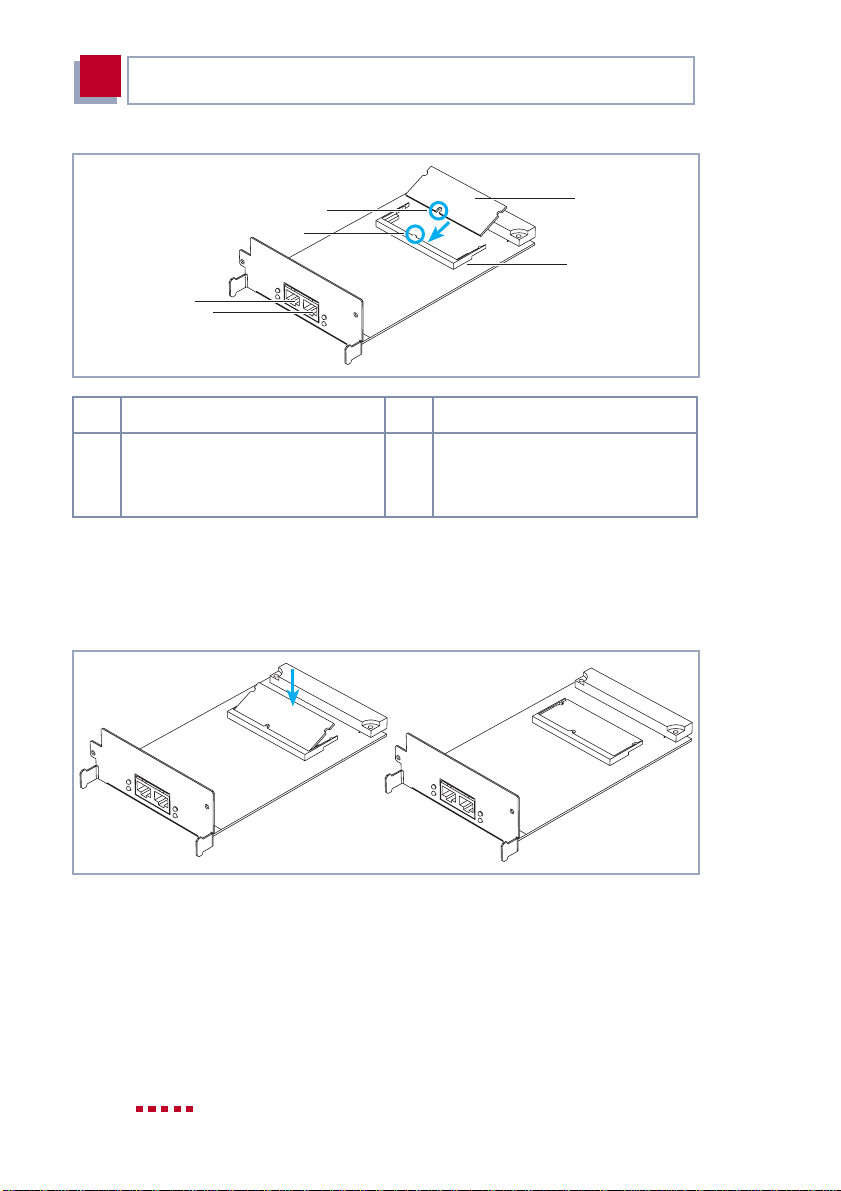
1 Kodierung 3 Fassung
2 Ressourcenkarte für Ver-
schlüsselung und Kompression
Bild 2-8: Ressourcenkarte für Verschlüsselung und Kompression mit LAN-Karte
4 LAN-Schnittstellen
2
3
➤ Setzen Sie die Ressourcenkarte schräg von oben in diedafür vorgesehene
Fassung (siehe Bild 2-8, Seite 16). Achten Sie dabei auf die korrekte Orientierung (Kodierung).
Bild 2-9: Ressourcenkarte für Verschlüsselung und Kompression auf LAN-Karte
➤ Drücken Sie die Ressourcenkarte vorsichtig nach unten, bis sie in die bei-
den seitlichen Laschen einrastet (siehe Bild 2-9, Seite 16).
16 X4100/200/300 Einbau
Page 17
Erweiterungskarte mit Ressourcenkarte(n) ausstatten
2
Ressourcenkarte für Verschlüsselung und Kompression
abnehmen
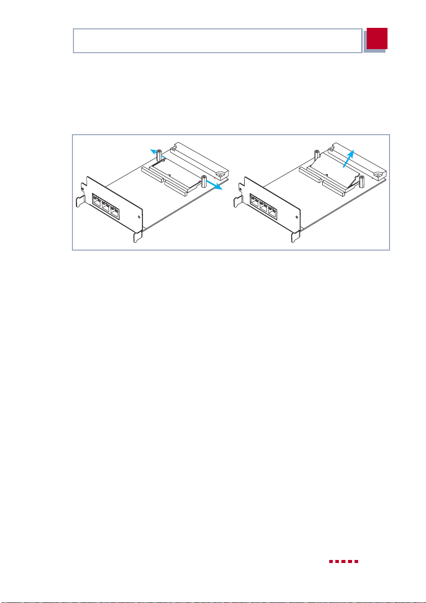
Wenn Sie die Ressourcenkarte für Verschlüsselung und Kompression von der
LAN-Erweiterungskarte entfernen wollen, gehen Sie folgendermaßen vor:
Bild 2-10: Ressourcenkarte für Verschlüsselung und Kompression von LAN-Karte
entfernen
➤ Drücken Sie die beiden seitlichen Laschen der Fassung leicht nach außen
(siehe Bild 2-10, Seite 17).
Die Ressourcenkarte richtet sich auf.
➤ Entnehmen Sie die Ressourcenkarte.
X4100/200/300 Einbau 17
Page 18

2
Installation der Erweiterungskarte und Ressourcenkarte(n)
2.3 Erweiterungskarte einbauen
Achtung!
Der Einbau der PRI/G.703-Erweiterungskarte bzw. der Einbau
von Ressourcenkarten in eine Erweiterungskarte führt zu verstärkter Wärmeentwicklung. Um die Schädigung von Bauteilen zu
vermeiden, ist der Einsatz einer Lüfterkassette zwingend erforderlich!
➤ Setzen Sie bei Verwendung der PRI/G.703-Erweiterungskar-
te oder einer Erweiterungskarte mit Ressourcenkarte(n) im
X4100/200/300-Einbaugerät die Lüfterkassette ein.
Sie können die Lüfterkassette von Ihrem Lieferanten käuflich erwerben.
Schließlich bauen Sie die Erweiterungskarte in den dafür vorgesehenenSteckplatz ein (siehe Bild 2-1, Seite 9):
➤ Nehmen Sie die Erweiterungskarte und stecken Sie sie in den dafür vorge-
sehenen Steckplatz in das Gehäuse, bis sie in den Steckverbinder des
Steckplatzes eingerastet ist. Kartenführungen ermöglichen ein sicheres
Stecken der Erweiterungskarte.
➤ Nachdem die Erweiterungskarte eingerastet ist, befestigen Sie sie mit den
beiden Schrauben, die Sie zuvor von der Blindabdeckung gelöst oder von
der auszutauschenden Erweiterungskarte behalten haben, am Gehäuse.
18 X4100/200/300 Einbau
Page 19

Erweiterungskarte einbauen
3
3 Wiederinbetriebnahme
Nach dem Einbau der Erweiterungskarte können Sie X4100/200/300 nun wieder in Betrieb nehmen. Die Erweiterungskarte wird beim Booten von X4100/
200/300 automatisch erkannt. Mit dem Setup Tool können Sie gegebenenfalls
erforderliche Lizenzen eintragen und den erfolgreichen Einbau der Karte überprüfen.
Lizenzen sind erhältlich, um
■ auf der PRI-Erweiterungskarte
– eine PRI-Schnittstelle (1PRI)
– eine G.703-Schnittstelle (1G.703)
– eine PRI-Schnittstelle und eine G.703-Schnittstelle
(1PRI + 1G.703)
– zwei PRI-Schnittstellen (2PRI)
– zwei G.703-Schnittstellen (2G.703)
freizuschalten
■ auf der 2BRI-Erweiterungskarte eine weitere BRI-Schnittstel-
le freizuschalten (3BRI)
■ die Ressourcenkarte XT-Q bzw. XT-S (mit 4 bzw. 8 Digital-
modems) zu einer Ressourcenkarte XT-M (mit 12 Digitalmodems) aufzurüsten
Die entsprechenden Lizenzen können Sie gegebenenfalls bei
Ihrem Händler erwerben.
Gehen Sie folgendermaßen vor, um X4100/200/300 mit Erweiterungskarte in
Betrieb zu nehmen:
➤ Stecken Sie die benötigten Schnittstellenkabel Ihrer Erweiterungskarte in
die dafür vorgesehenen Buchsen. Kabel können Sie gegebenenfalls beiIhrem Händler erwerben.
➤ Schließen Sie das X4100/200/300-Grundgerät an wie im Handbuch be-
schrieben.
X4100/200/300 Einbau 19
Page 20

3
Wiederinbetriebnahme
➤ Rufen Sie das Setup Tool auf.
Das folgende Menü öffnet sich:
X4100/200/300 Setup Tool BinTec Access Networks GmbH
MyRouter
Licenses System
LAN: CM-100BT, Fast Ethernet Module: CM-PRI, ISDN S2M
WAN: CM-1BRI, ISDN S0
Serial-WAN: CM-SERIAL, Serial Resources: XT-S
WAN Partner
IP PPP MODEM CREDITS CAPI QoS
Configuration Management
Monitoring and Debugging
Exit
Je nach Bestückung von X4100/200/300 kann sich Ihr Setup-Tool-Hauptmenü
von dem Beispiel unterscheiden.
➤ Tragen Sie gegebenenfalls im Menü
L
ICENSES
erforderliche Lizenz(en) ein.
Folgende Bestandteiledes Setup Tools müssen nacherfolgreichem Einbau der
Erweiterungskarte vorhanden sein:
■ Bei eingebauter ISDN-BRI-Karte:
■ Bei eingebauter ISDN-PRI-Karte:
■ Bei eingebauter LAN-Karte:
■ Bei Ressourcenkarten mit Digitalmodems:
M
ODULE
M
ODULE
: CM-1BRI, ISDN S0
M
ODULE
: CM-PRI, ISDN S2M
: CM-100BT, F
MODEM
.
.
ASTETHERNET
.
.
ZurKonfiguration Ihrer Erweiterungskartekonsultieren Sie bittedas X4100/200/
300-Benutzerhandbuch (ab Version 1.3). Die Beschreibung der Schnittstellen
finden Sie ebenfalls dort.
20 X4100/200/300 Einbau
Page 21

Scope of Supply
1
1 Welcome
You have purchased an expansion card and/or a resource card(s) to be installed in the basic unit of X4100/200/300. These installation instructions will
help you to quickly and easily upgrade your X4100/200/300. In addition to the
overall functionality ofthe basic unit of X4100/200/300, you cannow avail of the
extra functions of the expansion card and/or resource card.
This installation guide is structured as follows:
■ Installation of the expansion card or resource card(s)
■ Bringing back into operation and testing
1.1 Scope of Supply
The scope of supply covers:
■ for a WAN interface card for ISDN-BRI (X4E-2/3BRI):
– expansion card (packed in an antistatic bag)
– 3 ISDN cables
– 2 spacer pins with 2 Phillips screws and 2 washers (if not pre-assem-
bled)
– installation guide
– license card, if required
■ for a WAN interface card for ISDN-PRI and/or G.703 (X4E-1/2PRI):
– expansion card (packed in an antistatic bag)
– 4 spacer pins with 4 Phillips screws and 4 washers (if not pre-assem-
bled)
– installation guide
– license card, if required
■ for a LAN interface card for 10/100 Mbps (X4E-2FE):
– expansion card (packed in an antistatic bag)
X4100/200/300 Installation 21
Page 22

1
Welcome
– installation guide
■ for a resource card with digital modems (XT-Q, XT-S, XT-M, XT-2M or
XT-L):
– expansion card (packed in an antistatic bag)
– installation guide
– 2 Phillips screws and 2 washers (if spacer pins not pre-assembled)
■ for a resource card for encryption and compression (XT-ENC):
– expansion card (packed in an antistatic bag)
– installation guide
■ for a resource card for faster generation of encryption keys (XT-VPN):
– expansion card (packed in an antistatic bag)
– installation guide
1.2 Tool Required
For the mounting of an expansion card or resource card, you need a Phillips
screwdriver to remove the dummy cover and to mount the expansion card and
the resource card(s) with digital modems.
22 BinTec Access Networks GmbH
Page 23

Remove Dummy Cover or Expansion Card
2
2 Installation of the Expansion Card
and Resource Card(s)
Caution!
Electrostatic charges can damage electronic components. Please
observe the following precautions to avoid damaging components:
➤ Ground yourself before unpacking the expansion card or re-
source card and before carrying out installation work on the
equipment.
➤ Only grip printed circuit boards at the edges and do not touch
cables or components.
2.1 Remove Dummy Cover or Expansion Card
Firstly, remove the dummy cover of the expansion slot of the basic unit of
X4100/200/300 or remove an expansion card that is already installed.
Danger!
Do not touch any parts inside the extension slot when installing or
replacing the extension card. There is a risk of electric shock!
➤ Do not touch any parts inside the extension slot of
X4100/200/300!
X4100/200/300 Installation 23
Page 24

2
Installation of the Expansion Card and Resource Card(s)
Caution!
An extension card must not be installed or replaced during operation.X4100/200/300 must alwaysbe disconnected fromthe power
supply first, otherwise there is a risk of damaging both
X4100/200/300 and the extension card.
If, however, you carry out the installation of an expansion card
during operation, the guarantee is rendered invalid.
➤ Always disconnect the power cord of X4100/200/300 before
you insert or replace the expansion card.
➤ Do not connect X4100/200/300 to the power supply until the
equipment is completely installed and you have rechecked
the installation.
Proceed as follows:
➤ Disconnect the power cord of X4100/200/300.
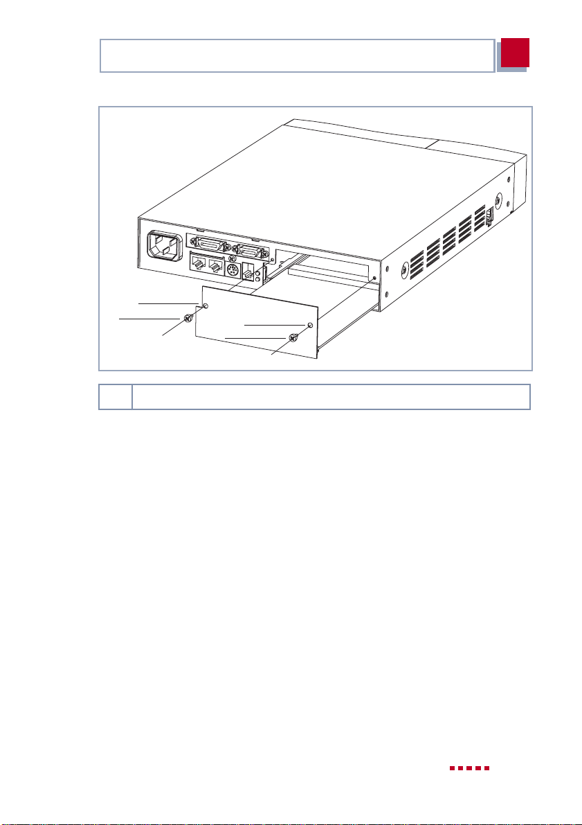
➤ Undo the screws of the dummy cover or the expansioncard installed in the
slot. (see figure 2-1, page 25).
➤ Remove thedummy cover or withdraw the existing expansion card from the
slot.
➤ Keep the two screws of the dummy cover, as these are used for fixing the
expansion card.
24 BinTec Access Networks GmbH
Page 25
Equipping an Expansion Card with a Resource Card(s)
1
2
1,2 Hole and screw for fixing the expansion card
Figure 2-1: Installing or removing an expansion card
1
2
2
2.2 Equipping an Expansion Card with a Resource Card(s)
If you want to equip your expansion card with a resource card(s), mount it as
described in thenext step. If you want to operate the expansion card without a
resource card(s), continue with chapter 2.3, page 33.
X4100/200/300 Installation 25
Page 26

2
Installation of the Expansion Card and Resource Card(s)
Caution!
An installed PRI/G.703 expansion card and installed expansion
cards with resource modules produce heat. Therefore, the additional installation of the fan unit is necessary to avoid damaging
components!
➤ Insert the fan unit when you install the PRI/G.703 expansion
card or expansion cards with resource cards in
X4100/200/300.
You can purchase the fan unit from your vendor.
The following resource cards are available:
■ Resource cards with digital modems (XT-Q, XT-S, XT-M, XT-2M and XT-L)
for ISDN-PRI and ISDN-BRI cards.
■ Resource cards for encryption and compression (XT-ENC) for ISDN-BRI
and LAN cards.
■ Resource cards for a faster generation of encryption keys and for more
VPN connections (XT-VPN) for ISDN-PRI and ISDN-BRI cards.
2.2.1 ISDN BRI Expansion Card
The ISDNBRI expansion card can be equippedwith a resource card with digital
modems and/or with a resource cardfor encryptionand compression (XT-ENC
or XT-VPN). Firstly, mount the resource card for encryption and compression
and then the resource cardwith digital modems,if youwant to availof bothoptions.
Connecting resource cards for encryption and compression (XTENC or XT-VPN)
Proceed as follows:
➤ Take the resource card out of the antistatic bag.
26 BinTec Access Networks GmbH
Page 27
Equipping an Expansion Card with a Resource Card(s)
2
4
1
1
5
5
5
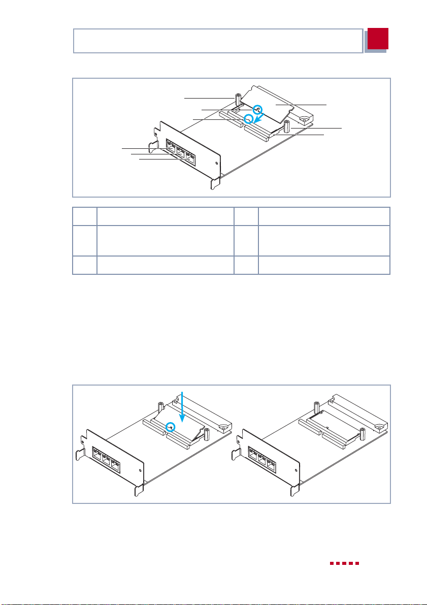
1 Coding 4 Spacer pin
2 Resource card for encryption
and compression
3 Mounting frame
Figure 2-2: Resource card for encryption and compression with BRI card
5 ISDN BRI interfaces
2
4
3
➤ Mount the spacer pins (if not pre-assembled) on the expansion card (see
figure 2-2, page 27): Place a washer from above onto the corresponding
Phillips screw, fix the screw from below up through the expansion card, and
then mount the spacer pins.
➤ Place the resource card at an angle into the mounting frame. Make sure it
is the right way around (coding).
Figure 2-3: Resource card for encryption and compression on BRI card
X4100/200/300 Installation 27
Page 28
2
Installation of the Expansion Card and Resource Card(s)
➤ Carefully press the resourcecard down untilboth sides snapinto place (see
figure 2-3, page 27).
Removing resource cards for encryption and compression (XTENC or XT-VPN)
If you want to remove the resource card for encryption and compression from
the ISDN BRI expansion card, proceed as follows:
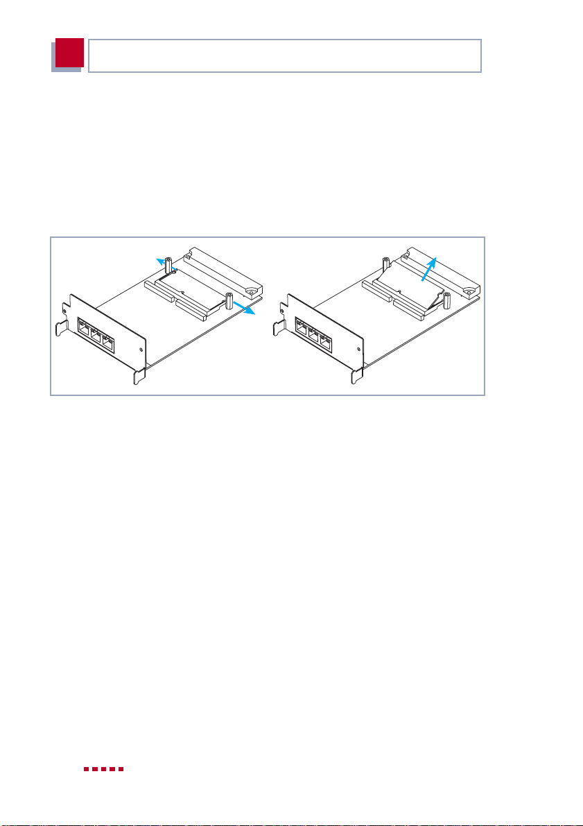
Figure 2-4: Removing resource card for encryption and compression from BRI card
➤ Gently press both sides of the mounting frame outwards (see figure 2-4,
page 28).
The resource card will rise up.
➤ Remove the resource card.
Connecting a resource card with digital modems
Proceed as follows:
➤ Take the resource card out of the antistatic bag.
28 BinTec Access Networks GmbH
Page 29
Equipping an Expansion Card with a Resource Card(s)
4
2
5
3
6
6
6
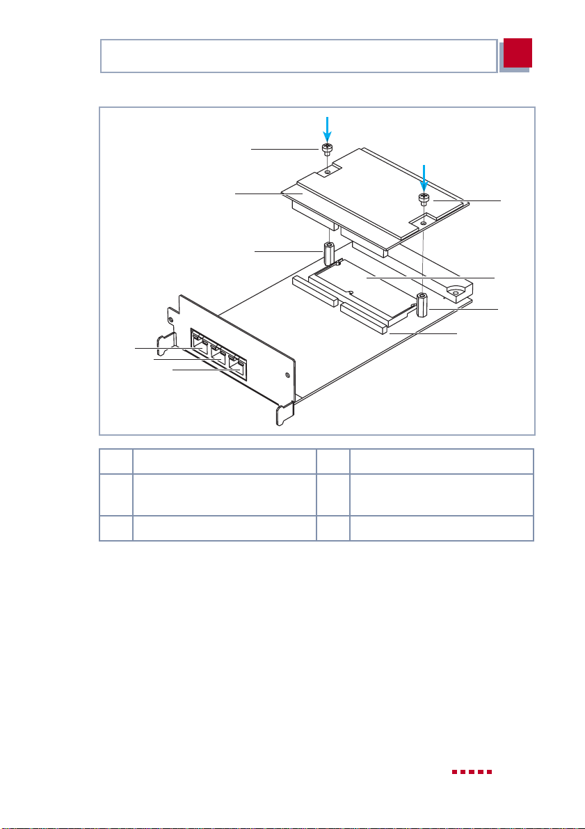
1 Connector 4 Screws
2 Resource card for encryption
and compression (optional)
3 Spacer pins 6 ISDN BRI interfaces
Figure 2-5: Resource card with digital modems with BRI card
5 Resource card with digital
modems
1
4
2
3
➤ Mount the spacer pins (if not pre-assembled) on the expansion card (see
figure 2-5, page 29), if you have not yet done so: Place a washer from
above onto the corresponding Phillips screw, fix the screw from below up
through the expansion card, and then mount the spacer pins.
➤ Connect the resource card from above onto the connector.
➤ Fasten the resource card by fixing the included screws into the spacer pins.
X4100/200/300 Installation 29
Page 30
2
Installation of the Expansion Card and Resource Card(s)
2.2.2 ISDN-PRI Expansion Card / G.703 Expansion Card
The ISDN-PRI card can be fitted with a maximum of two resource cards with
digital modems.
Proceed as follows:
➤ Take the resource card out of the antistatic bag.
4
4
2
2
3
2
1
2
1 First resource card with digital
modems
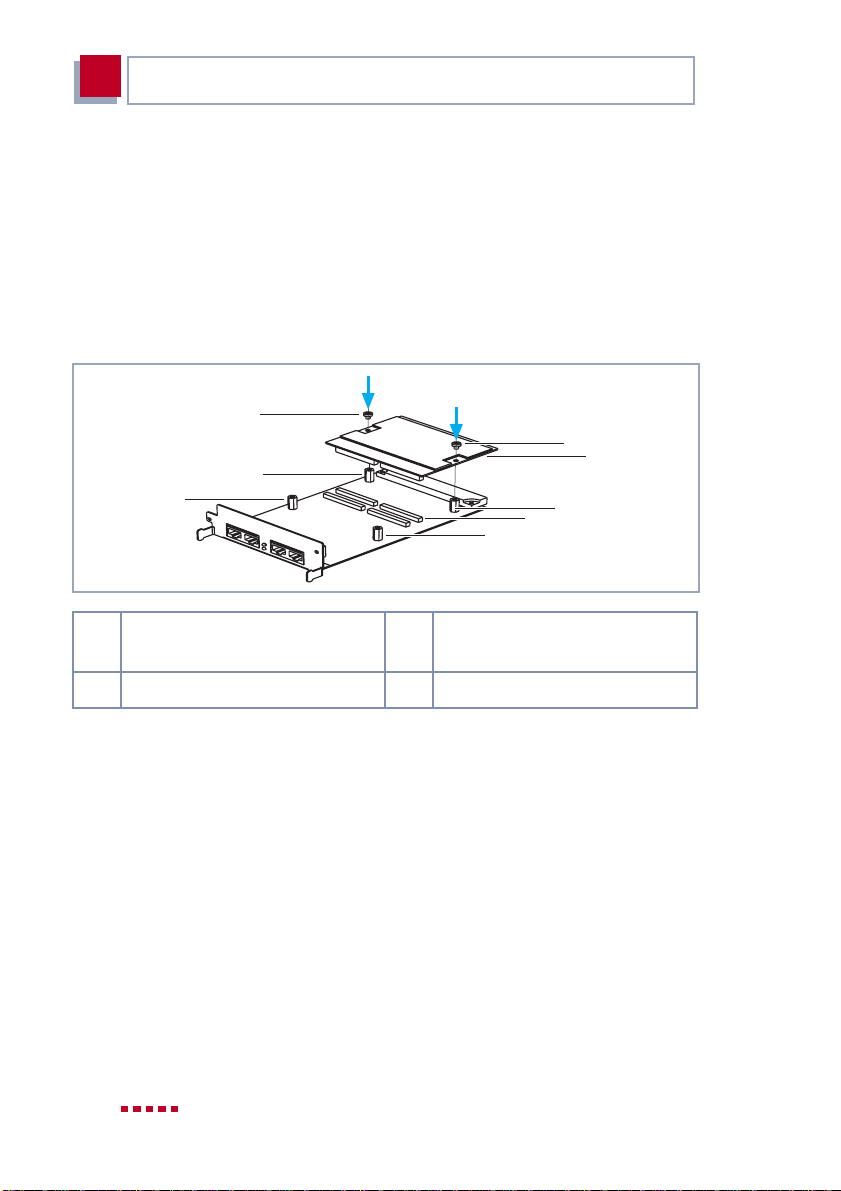
2 Spacer pins 4 Screws
Figure 2-6: First resource card with digital modems with ISDN-PRI card
3 Connector for first resource
card
➤ Mount the spacer pins (if not pre-assembled) on the expansion card (see
figure 2-6, page 30): Place a washer from above onto the corresponding
Phillips screw, fix the screw from below up through the expansion card, and
then mount the spacer pins.
➤ Place the first resource card down onto the corresponding connector (see
figure 2-6, page 30).
➤ Fasten the resource card by fixing the included screws into the spacer pins.
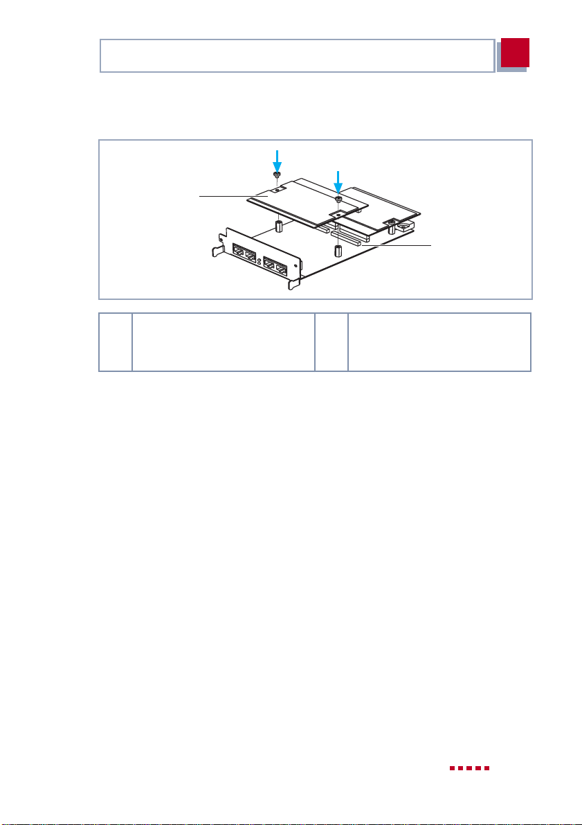
➤ If necessary, connect the second resource card from above onto the sec-
ond connector (see figure 2-7, page 31).
30 BinTec Access Networks GmbH
Page 31
Equipping an Expansion Card with a Resource Card(s)
2
➤ Fasten the second resource card by fixing the included screws into the
spacer pins.
1
2
1 Second resource card with
digital modems
Figure 2-7: Second resource card with digital modems with ISDN-PRI card
2 Connector for second
resource card with digital
modems
2.2.3 LAN Expansion Card
A resource card for encryptionand compression canbe installed on the LAN expansion card.
Connecting resource cards for encryption and compression
Proceed as follows:
➤ Take the resource card out of the antistatic bag.
X4100/200/300 Installation 31
Page 32
2
Installation of the Expansion Card and Resource Card(s)
1
1
4
4
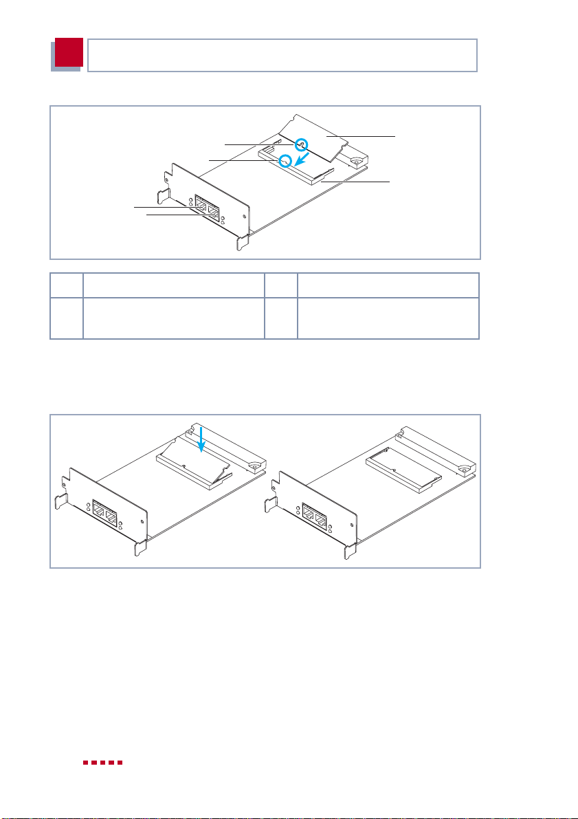
1 Coding 3 Mounting frame
2 Resource cards for encryption
and compression
Figure 2-8: Resource card for encryption and compression with LAN card
4 LAN interfaces
2
3
➤ Place the resource card at an angle into the mounting frame. Make sure it
is the right way around (coding).
Figure 2-9: Resource card for encryption and compression on LAN card
➤ Carefully press the resourcecard down untilboth sides snapinto place (see
figure 2-9, page 32).
32 BinTec Access Networks GmbH
Page 33
Installing the Expansion Card
2
Removing resource cards for encryption and compression
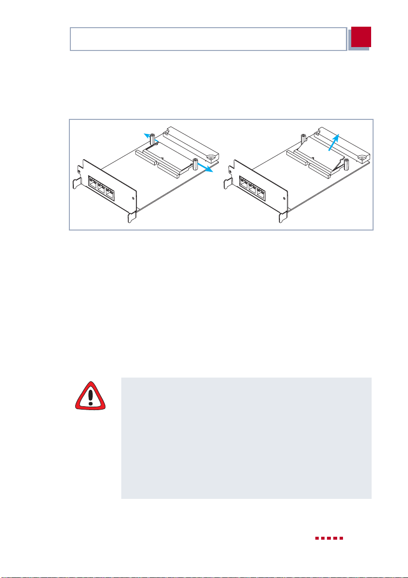
If you want to remove the resource card for encryption and compression from
the LAN expansion card, proceed as follows:
Figure 2-10: Removing resource card for encryption and compression from LAN card
➤ Gently press both sides of the mounting frame outwards (see figure 2-10,
page 33).
The resource card will rise up.
➤ Remove the resource card.
2.3 Installing the Expansion Card
Caution!
An installed PRI/G.703 expansion card and installed expansion
cards with resource modules produce heat. Therefore, the additional installation of the fan unit is necessary to avoid damaging
components!
➤ Insert the fan unit when you install the PRI/G.703 expansion
card or expansion cards with resource cards in
X4100/200/300.
You can purchase the fan unit from your vendor.
X4100/200/300 Installation 33
Page 34

2
Installation of the Expansion Card and Resource Card(s)
Finally, insert the expansion card into the appropriate slot (see figure 2-1,
page 25):
➤ Push the extension card into the slotprovided in the housinguntil it engag-
es in the slot connector.Card guidesensure thatthe extension card is reliably plugged in.
➤ Once the extension cardengages in the connector, fix it to the housing with
the two screws you previously unscrewed from the dummy cover or the exchanged extension card.
34 BinTec Access Networks GmbH
Page 35

Installing the Expansion Card
3
3 Beginning Operation
After installing the expansion card, you can start X4100/200/300 again. On
booting, the expansion cardis automatically recognized by X4100/200/300.By
using Setup Tool, you canenter any necessarylicenses if required, and you can
verify the success of the installation of the card.
Licenses are obtainable
■ to activate on the PRI expansion card
– a PRI interface (1PRI)
– a G.703 interface (1G.703)
– a PRI interface and a G.703 interface (1PRI + 1G.703)
– two PRI interfaces (2PRI)
– two G.703 interfaces (2G.703)
■ to activate a further BRI interface (3BRI) on the 2BRI expan-
sion card
■ to upgradethe resource card XT-Q orXT-S (with 4 or 8digital
modems respectively) to a resource card XT-M (with 12 digital modems)
When required, these licenses are obtainable from your local
dealer.
Proceed as follows to operate X4100/200/300 with an expansion card:
➤ Plug the necessary interface cables of your extension card into the sockets
provided. If required, you can obtain the cables from your local dealer.
➤ Connect the basic unit of X4100/200/300 as described in the User´s Guide.
➤ Open the Setup Tool.
X4100/200/300 Installation 35
Page 36

3
Beginning Operation
The following Menu opens:
X4100/200/300 Setup Tool BinTec Access Networks GmbH
MyRouter
Licenses System
LAN: CM-100BT, Fast Ethernet Module: CM-PRI, ISDN S2M
WAN: CM-1BRI, ISDN S0
Serial-WAN: CM-SERIAL, Serial Resources: XT-S
WAN Partner
IP PPP MODEM CREDITS CAPI QoS
Configuration Management
Monitoring and Debugging
Exit
Depending on your X4100/200/300 setup, your Setup Tool main menumay differ from the example.
➤ Enter any necessary licenses in the
L
ICENSES
menu.
The following elements should appear in Setup Tool aftersuccessful installation
of the expansion card:
■ When an ISDN-BRI card is installed:
■ When an ISDN-PRI card is installed:
■ When a LAN card is installed:
■ When resource cards with digital modems are installed:
MODULE
MODULE
MODULE
: CM-1BRI, ISDN S0
: CM-PRI, ISDN S2M
: CM-100BT, F
ASTETHERNET
MODEM
.
.
.
.
For the configuration of your configuration card, please refer to the
X4100/200/300 User´s Guide (from version 1.3). You will also find the descrip-
tion of the interfaces there.
36 BinTec Access Networks GmbH
 Loading...