

Operating Manual
Translation of the original operating manual
KBF / KBF-UL (E6)
Constant climate chambers with program control
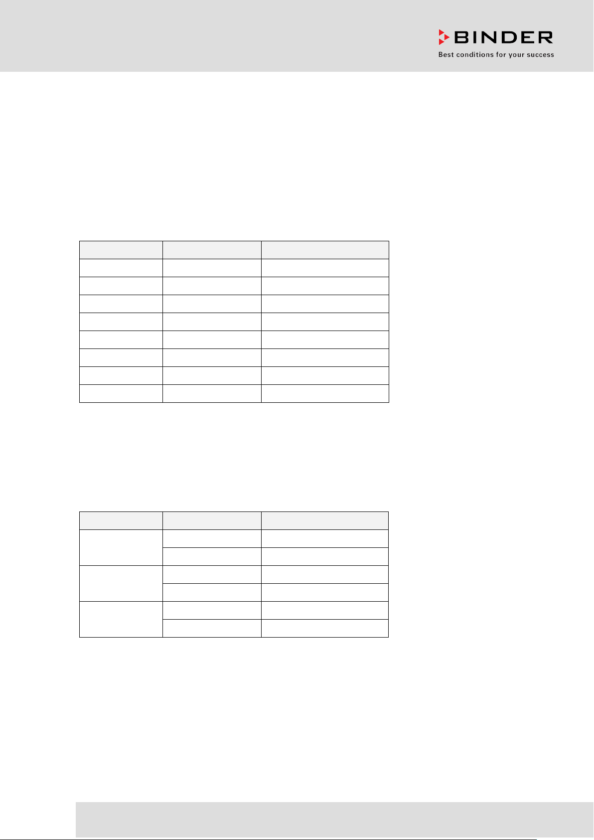
Model Model version Art. No.
KBF 115 KBF115-230V 9020-0320, 9120-0320
KBF 115-UL KBF115UL-240V 9020-0321, 9120-0321
KBF 240 KBF240-230V 9020-0322, 9120-0322
KBF 240-UL KBF240UL-240V 9020-0323, 9120-0323
KBF 720 KBF720-230V 9020-0324, 9120-0324
KBF 720-UL KBF720UL-240V 9020-0325, 9120-0325
KBF 1020 KBF1020-230V 9020-0326, 9120-0326
KBF 1020-UL KBF1020UL-240V 9020-0327, 9120-0327
KMF (E6)
Constant climate chambers
with enlarged temperature and humidity range
with program control
Model Model version Art. No.
KMF 115 KMF115-230V 9020-0341, 9120-0341
KMF115-240V 9020-0342, 9120-0342
KMF 240 KMF240-230V 9020-0343, 9120-0343
KMF240-240V 9020-0344, 9120-0344
KMF 720 KMF720-230V 9020-0345, 9120-0345
KMF720-240V 9020-0346, 9120-0346
BINDER GmbH
Address: Post office box 102, 78502 Tuttlingen, Germany Phone: +49 7462 2005 0
Fax: +49 7462 2005 100 Internet: http://www.b ind er -world.com
E-mail: info@binder-world.com Service Hotline: +49 7462 2005 555
Service Fax: +49 7462 2005 93 555 Service E-Mail: service@binder-world.com
Service Hotline USA: +1 866 885 9794 or +1 631 224 4340 x3
Service Hotline Asia Pacif ic: +852 390 705 04 or +852 390 705 03
Service Hotline Russia and CIS: +7 495 988 15 16
Issue 04/2020 Art. No. 7001-0319

Content
1. SAFETY .................................................................................................................. 7
1.1 Personnel Qualification ....................................................................................................................... 7
1.2 Operating manual ................................................................................................................................ 7
1.3 Legal considerations ........................................................................................................................... 7
1.4 Structure of the safety instructions ...................................................................................................... 8
1.4.1 Signal word panel ...................................................................................................................... 8
1.4.2 Safety alert symbol .................................................................................................................... 8
1.4.3 Pictograms ................................................................................................................................. 9
1.4.4 Word message panel structure ................................................................................................. 9
1.5 Localization / position of safety labels on the chamber .................................................................... 10
1.6 Type plate.......................................................................................................................................... 11
1.7 General safety instructions on installing and operating the chambers ............................................. 12
1.8 Intended use ..................................................................................................................................... 14
1.9 Foreseeable Misuse .......................................................................................................................... 15
1.10 Residual Risks .................................................................................................................................. 16
1.11 Operating instructions ....................................................................................................................... 17
1.12 Measures to prevent accidents ......................................................................................................... 18
1.13 Resistance of the humidity sensor against harmful substances ....................................................... 19
2. CHAMBER DESCRIPTION .................................................................................. 20
2.1 Chamber overview ............................................................................................................................ 21
2.2 Instrument panel ............................................................................................................................... 21
2.3 Lateral control panels ........................................................................................................................ 22
2.4 Rear view with water connections ..................................................................................................... 23
3. COMPLETENESS OF DELIVERY, TRANSPORTATION, STORAGE, AND
INSTALLATION .................................................................................................... 24
3.1 Unpacking, and checking equipment and completeness of delivery ................................................ 24
3.2 Guidelines for safe lifting and transportation ..................................................................................... 25
3.3 Storage .............................................................................................................................................. 25
3.4 Location of installation and ambient conditions ................................................................................ 26
4. INSTALLATION AND CONNECTIONS ............................................................... 28
4.1 Spacer for wall distance .................................................................................................................... 28
4.2 Wastewater connection ..................................................................................................................... 28
4.3 Freshwater supply ............................................................................................................................. 29
4.3.1 Automatic freshwater supply via water pipe ............................................................................ 29
4.3.2 Manual freshwater supply via external freshwater can (option) .............................................. 30
4.3.3 Connection kit for connecting the chamber to the water main ................................................ 30
4.3.4 Safety kit: Hose burst protection device with reflux protection device (available via BINDER
INDIVIDUAL customized solutions) ........................................................................................ 31
4.4 Electrical connection ......................................................................................................................... 33
4.5 Connection of the voltage changer (option for KBF) ......................................................................... 34
5. FUNCTIONAL OVERVIEW OF THE MB2 CHAMBER CONTROLLER ............... 36
5.1 Operating functions in normal display ............................................................................................... 37
5.2 Display views: Normal display, program display, chart-recorder display .......................................... 38
5.3 Controller icons overview .................................................................................................................. 39
5.4 Operating modes ............................................................................................................................... 41
5.5 Controller menu structure .................................................................................................................. 42
5.5.1 Main menu ............................................................................................................................... 43
5.5.2 “Settings” submenu ................................................................................................................. 44
5.5.3 “Service” submenu .................................................................................................................. 44
5.6 Principle of controller entries ............................................................................................................. 45
5.7 Performance during and after power failures .................................................................................... 45
5.8 Performance when opening the door ................................................................................................ 46
KBF / KBF-UL + KMF (E6) 04/2020 page 2/163

6. START UP ............................................................................................................ 46
6.1 Turning on the chamber .................................................................................................................... 46
6.2 Controller settings upon start up ....................................................................................................... 46
6.3 Turning on/off humidity control .......................................................................................................... 47
7. SET-POINT ENTRY IN “FIXED VALUE” OPERATING MODE ........................... 48
7.1 Set-point entry for temperature, humidity, and fan speed through the “Setpoints” menu ................. 49
7.2 Direct setpoint entry for temperature and humidity via Normal display ............................................ 50
7.3 Special controller functions via operation lines ................................................................................. 50
8. TIMER PROGRAM: STOPWATCH FUNCTION .................................................. 51
8.1 Starting a timer program ................................................................................................................... 51
8.1.1 Performance during program delay time ................................................................................. 51
8.2 Stopping a running timer program .................................................................................................... 52
8.2.1 Pausing a running timer program ............................................................................................ 52
8.2.2 Cancelling a running timer program ........................................................................................ 52
8.3 Performance after the end of the program ........................................................................................ 52
9. TIME PROGRAMS ............................................................................................... 53
9.1 Starting an existing time program ..................................................................................................... 53
9.1.1 Performance during program delay time ................................................................................. 54
9.2 Stopping a running time program ...................................................................................................... 54
9.2.1 Pausing a running time program ............................................................................................. 54
9.2.2 Cancelling a running time program ......................................................................................... 54
9.3 Performance after the end of the program ........................................................................................ 54
9.4 Creating a new time program ............................................................................................................ 55
9.5 Program editor: program management ............................................................................................. 55
9.5.1 Deleting a time program .......................................................................................................... 56
9.6 Section editor: section management ................................................................................................. 57
9.6.1 Add a new program section ..................................................................................................... 58
9.6.2 Copy and insert or replace a program section ........................................................................ 58
9.6.3 Deleting a program section ..................................................................................................... 59
9.7 Value entry for a program section ..................................................................................................... 60
9.7.1 Section duration ....................................................................................................................... 60
9.7.2 Set-point ramp and set-point step ........................................................................................... 61
9.7.3 Special controller functions via operat ion lines ....................................................................... 62
9.7.4 Setpoint entry .......................................................................................................................... 63
9.7.5 Tolerance range ...................................................................................................................... 63
9.7.6 Repeating one or several sections within a time program ...................................................... 64
9.7.7 Saving the time program ......................................................................................................... 65
10. WEEK PROGRAMS ............................................................................................. 66
10.1 Starting an existing week program .................................................................................................... 66
10.2 Cancelling a running week program ................................................................................................. 66
10.3 Creating a new week program .......................................................................................................... 67
10.4 Program editor: program management ............................................................................................. 68
10.4.1 Deleting a week program......................................................................................................... 69
10.5 Section editor: section management ................................................................................................. 70
10.5.1 Add a new program section ..................................................................................................... 71
10.5.2 Copy and insert or replace a program section ........................................................................ 71
10.5.3 Deleting a program section ..................................................................................................... 72
10.6 Value entry for a program section ..................................................................................................... 72
10.6.1 Set-point ramp and set-point step modes ............................................................................... 72
10.6.2 Weekday .................................................................................................................................. 73
10.6.3 Start time ................................................................................................................................. 73
10.6.4 Setpoint entry .......................................................................................................................... 74
10.6.5 Special controller functions via operation lines ....................................................................... 74
KBF / KBF-UL + KMF (E6) 04/2020 page 3/163

11. NOTIFICATION AND ALARM FUNCTIONS ........................................................ 75
11.1 Notification and alarm messages overview ....................................................................................... 75
11.1.1 Notifications ............................................................................................................................. 75
11.1.2 Alarm messages ...................................................................................................................... 76
11.1.3 Messages concerning the humidity system............................................................................. 76
11.2 State of alarm .................................................................................................................................... 77
11.3 Resetting an alarm, list of active alarms ........................................................................................... 77
11.4 Tolerance range settings ................................................................................................................... 78
11.5 Activating / deactivating the audible alarm (alarm buzzer) ............................................................... 79
12. TEMPERATURE SAFETY DEVICES ................................................................... 79
12.1 Over temperature protective device (class 1) ................................................................................... 79
12.2 Overtemperature safety controller class 3.1 ..................................................................................... 79
12.2.1 Safety controller modes ........................................................................................................... 80
12.2.2 Setting the safety controller ..................................................................................................... 80
12.2.3 Message and measures in the state of alarm ......................................................................... 81
12.2.4 Function check ........................................................................................................................ 81
12.3 Temperature safety device class 3.3 (option) ................................................................................... 82
12.3.1 Temperature safety device class 3.1 ....................................................................................... 83
12.3.2 Temperature safety device class 3.2 ....................................................................................... 84
13. USER MANAGEMENT ......................................................................................... 85
13.1 Authorization levels and password protection................................................................................... 85
13.2 Log in ................................................................................................................................................. 88
13.3 Log out .............................................................................................................................................. 89
13.4 User change ...................................................................................................................................... 89
13.5 Password assignment and password change................................................................................... 90
13.5.1 Password change .................................................................................................................... 90
13.5.2 Deleting the password for an individual authorization level .................................................... 92
13.5.3 New password assignment for “service” or “admin” authorization level when the password
function was deactivated ........................................................................................................ 93
13.6 Activation code .................................................................................................................................. 94
14. GENERAL CONTROLLER SETTINGS ................................................................ 95
14.1 Selecting the controller’s menu language ......................................................................................... 95
14.2 Setting date and time ........................................................................................................................ 95
14.3 Selecting the temperature unit .......................................................................................................... 97
14.4 Display configuration ......................................................................................................................... 97
14.4.1 Adapting the display parameters ............................................................................................. 97
14.4.2 Touchscreen calibration .......................................................................................................... 98
14.5 Network and communication ............................................................................................................. 99
14.5.1 Serial interfaces ....................................................................................................................... 99
14.5.2 Ethernet ................................................................................................................................. 100
14.5.3 Web server ............................................................................................................................ 101
14.5.4 E-Mail..................................................................................................................................... 102
14.6 USB menu: Data transfer via USB interface ................................................................................... 103
15. GENERAL INFORMATION ................................................................................ 104
15.1 Service contact page ....................................................................................................................... 104
15.2 Current operating parameters ......................................................................................................... 104
15.3 Event list .......................................................................................................................................... 105
15.4 Technical chamber information ....................................................................................................... 105
15.5 Self-test function ............................................................................................................................. 106
16. CHART RECORDER DISPLAY ......................................................................... 108
16.1 Views ............................................................................................................................................... 108
16.1.1 Show and hide legend ........................................................................................................... 108
16.1.2 Switch between legend pages ............................................................................................... 108
KBF / KBF-UL + KMF (E6) 04/2020 page 4/163

Show and hide specific indications ........................................................................................ 109
16.1.3
16.1.4 History display ....................................................................................................................... 109
16.2 Setting the parameters .................................................................................................................... 112
17. HUMIDIFICATION / DEHUMIDIFICATION SYSTEM ......................................... 113
17.1 Function of the humidifying and dehumidifying system .................................................................. 115
18. DEFROSTING AT REFRIGERATING OPERATION .......................................... 116
19. OPTIONS ............................................................................................................ 117
19.1 APT-COM™ 4 Multi Management Software (option) ...................................................................... 117
19.2 RS485 interface (option) ................................................................................................................. 117
19.3 Data logger kits (option) .................................................................................................................. 117
19.4 Analog outputs for temperature and humidity (option) .................................................................... 118
19.5 Zero-voltage relay alarm outputs for temperature and humidity (option) ........................................ 118
19.6 Water protected internal socket (option for KBF) ............................................................................ 119
19.7 Additional flexible Pt 100 temperature sensor (available via BINDER INDIVIDUAL customized
solutions) ......................................................................................................................................... 120
19.8 Object temperature display with flexible Pt 100 temperature sensor (option) ................................ 120
19.9 External freshwater and wastewater cans (option) ......................................................................... 121
19.9.1 Mounting the freshwater can ................................................................................................. 121
19.9.2 Mounting the wastewater can ................................................................................................ 123
19.9.3 Mounting with wastewater recycling ...................................................................................... 124
19.10 BINDER Pure Aqua Servic e (opt ion) .............................................................................................. 125
20. CLEANING AND DECONTAMINATION ............................................................ 125
20.1 Cleaning .......................................................................................................................................... 125
20.2 Decontamination / chemical disinfection ......................................................................................... 127
21. MAINTENANCE AND SERVICE, TROUBLESHOOTING, REPAIR, TESTING . 128
21.1 General information, personnel qualification................................................................................... 128
21.2 Maintenance intervals, service ........................................................................................................ 128
21.3 Simple troubleshooting .................................................................................................................... 129
21.4 Sending the chamber back to BINDER GmbH ............................................................................... 132
22. DISPOSAL.......................................................................................................... 133
22.1 Disposal of the transport packing .................................................................................................... 133
22.2 Decommissioning ............................................................................................................................ 133
22.3 Disposal of the chamber in the Federal Republic of Germany ....................................................... 133
22.4 Disposal of the chamber in the member states of the EU except for the Federal Republic of
Germany.......................................................................................................................................... 134
22.5 Disposal of the chamber in non-member states of the EU ............................................................. 136
23. TECHNICAL DESCRIPTION .............................................................................. 137
23.1 Factory calibration and adjustment ................................................................................................. 137
23.2 Over current protection ................................................................................................................... 137
23.3 Definition of usable volume ............................................................................................................. 137
23.4 KBF / KBF-UL Technical Data ........................................................................................................ 138
23.5 KMF technical data ......................................................................................................................... 139
23.6 Equipment and options (extract) ..................................................................................................... 141
23.7 Accessories and spare parts (extract) ............................................................................................ 142
23.8 Dimensions size 115 ....................................................................................................................... 144
23.9 Dimensions size 240 ....................................................................................................................... 145
23.10 Dimensions size 720 ....................................................................................................................... 146
23.11 Dimensions size 1020 ..................................................................................................................... 147
KBF / KBF-UL + KMF (E6) 04/2020 page 5/163

24. CERTIFICATES AND DECLARATIONS OF CONFORMITY ............................. 148
24.1 EU Declaration of Conformity for KBF ............................................................................................ 148
24.2 EU Declaration of Conformity for KMF ............................................................................................ 151
24.3 Certificate for the GS mark of conformity of the “Deutsche Gesetzliche Unfallversicherung e.V.“
(German Social Accident Insurance) DGUV ................................................................................... 154
25. PRODUCT REGISTRATION .............................................................................. 156
25.1 Registering a BINDER chamber ..................................................................................................... 156
25.2 Multi Management Software APT-COM™ 4 BASIC-Edition ........................................................... 157
26. CONTAMINATION CLEARANCE CERTIFICATE ............................................. 158
26.1 For chambers located outside USA and Canada ........................................................................... 158
26.2 For chambers located in USA and Canada .................................................................................... 161
KBF / KBF-UL + KMF (E6) 04/2020 page 6/163
Dear customer,
For the correct operation of the c hambers, it is im portant that you read this operat ing manual complete ly
and careful ly and obser ve all instr uctions as indicate d. Failur e to read, un derstan d and follow the instr uctions may result in personal injury. It can also lead to damage to the chamber and/or poor equipment
performance.
1. Safety
1.1 Personnel Qualification
The chamber mus t only be installed, tes ted, and started u p by personnel qualified for as sembly, startup,
and operation of the chamber. Qualified personnel are persons whose professional education,
knowledge, experience an d k nowledge of rele vant stan dards all ow th em to assess, c arr y out, and identif y
any potential hazards i n the work assigned to them. The y must hav e been train ed and inst ructed, a nd be
authorized, to work on the chamber .
The chamber should only be operated by laboratory personnel especially trained for this purpose and
familiar with all prec autiona r y measures required f or work ing in a lab orator y. Obs erve t he nationa l reg ul ations on minimum age of laboratory personnel.
1.2 Operating manual
This operating manual is par t of the components of delivery. Always keep it hand y for reference in the
vicinity of the chamber. If selling the unit, hand over the operating manual to the purchaser.
To avoid injuries and damage obs erve the safety instructions of the opera ting manual. Failure to follow
instructions and safety precautions can lead to significant risks.
DANGER
Dangers due to failure to observe the instructions and safety precautions.
Serious injuries and chamber damage. Risk of death.
Observe the safety instructions in this Operating Manual.
Follow the operating procedures in this Operating Manual.
Carefully read the complete operating instructions of the chamber prior to installing and
using the chamber.
Keep the operating manual for future reference
Make sure that all persons who use the chamber and its associated work equipment have
read and understood the Operating Manual.
This Operating Manu al is supplem ented and updated as needed. Alwa ys use the mos t recent version of
the Operating Manual. When in doubt, call the BINDER Service Hotline for information on the up-todateness and validity of this Operating Manual.
1.3 Legal considerations
This operating m anual is for informationa l purposes only. It conta ins information for c orrect and safe i nstalling, start-up, operat ion, decommissioning, cleani ng and maintenance of the product. No te: the contents and the product described are subject to change without notice.
KBF / KBF-UL + KMF (E6) 04/2020 page 7/163
Understanding and obs erving the instructions in this operat ing manual are prerequisites for ha zard-free
use and safety during oper ation and m aintenance. Im ages are to pro vide basic u nderstandi ng. The y may
deviate from the actual ver sion of the cham ber. The actual sc ope of deliver y can, due to option al or special design, or due to recent technical changes, deviate from the information and illustrations in these
instructions this op erating manual. In no event s hall BINDER be held liable for any damages, direct or
incidental arising out of or related to the use of this manual.
This operating manual ca nnot cover all conc eivable applicati ons. If you would like additional inform ation,
or if special problem s arise that are not suff iciently addressed in this m anual, please ask your dealer or
contact us directly, e.g. by phone at the number located on page one of this manual
Furthermore, we emphas ize that the contents of this operating m anual are not part of an earlier or existing agreement, descripti on, or legal rel ations hip, nor d o they m odif y such a relations hip. All obl igations on
the part of BINDER deriv e from the respec tive purchase contrac t, which also co ntains the entire and exclusively valid stat ement of warrant y administration a nd the genera l terms and condit ions, as well as t he
legal regulations va lid at the time the contrac t is concluded. The statem ents in this manual n either augment nor restrict the contractual warranty provisions.
1.4 Structure of the safety instructions
In this operating manual, t he following safety definitions and symbols indicate dangerous situations following the harmonization of ISO 3864-2 and ANSI Z535.6.
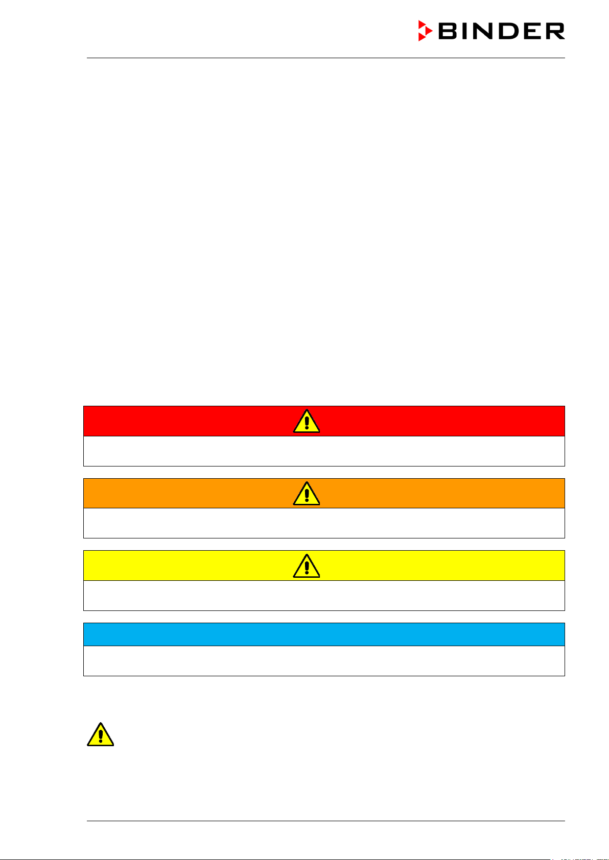
1.4.1 Signal word panel
Depending on the probability of serious consequences, potential dangers are identified with a signal
word, the corresponding safety color, and if appropriate, the safety alert symbol.
DANGER
Indicates an imminently hazardous situation that, if not avoided, will result in death or serious (irreversible) injury.
WARNING
Indicates a potentially hazardous situation which, if not avoided, could result in death or serious (irreversible) injury.
CAUTION
Indicates a potentially hazardous situation which, if not avoided, may result in moderate or minor (reversible) injury.
NOTICE
Indicates a potentially hazardous situation which, if not avoided, may result in damage to the product
and/or its functions or of a property in its proximity.
1.4.2 Safety alert symbol
Use of the safety alert symbol indicates a risk of injury.
Observe all measures that are marked with the safety alert symbol in order to avoid death or
injury.
KBF / KBF-UL + KMF (E6) 04/2020 page 8/163
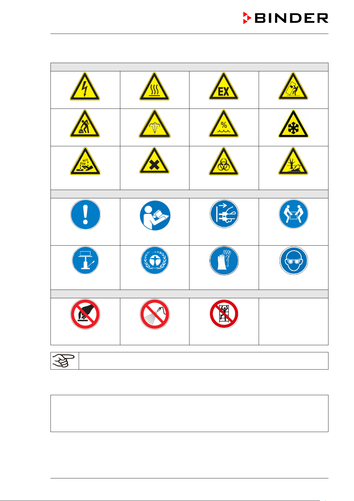
Warning signs
Electrical hazard
Hot surface
Scalding hazard
Danger of frost
or chemical burns
Mandatory action signs
instructions
assistance
Prohibition signs
water
1.4.3 Pictograms
Lifting hazard
Risk of corrosion and /
Mandatory regulation
Harmful substances
Read operating
Explosive atmosphere
High humidity
Biohazard
Disconnect the power
plug
Stability hazard
Pollution Hazard
Lift with several persons
Lift with mechanical
Do NOT touch
Information to be observed in order to ensure optimum function of the product.
Environment protection
Do NOT spray with
Wear protective gloves
Do NOT climb
Wear safety goggles
1.4.4 Word message panel structure
Type / cause of hazard.
Possible consequences.
∅ Instruction how to avoid the hazard: prohibition
Instruction how to avoid the hazard: mandatory action.
Observe all other notes and inf ormation not necessarily emphasi zed in the same way, in order to avoid
disruptions that could result in direct or indirect injury or property damage.
KBF / KBF-UL + KMF (E6) 04/2020 page 9/163
Pictograms (warning signs)
Service label
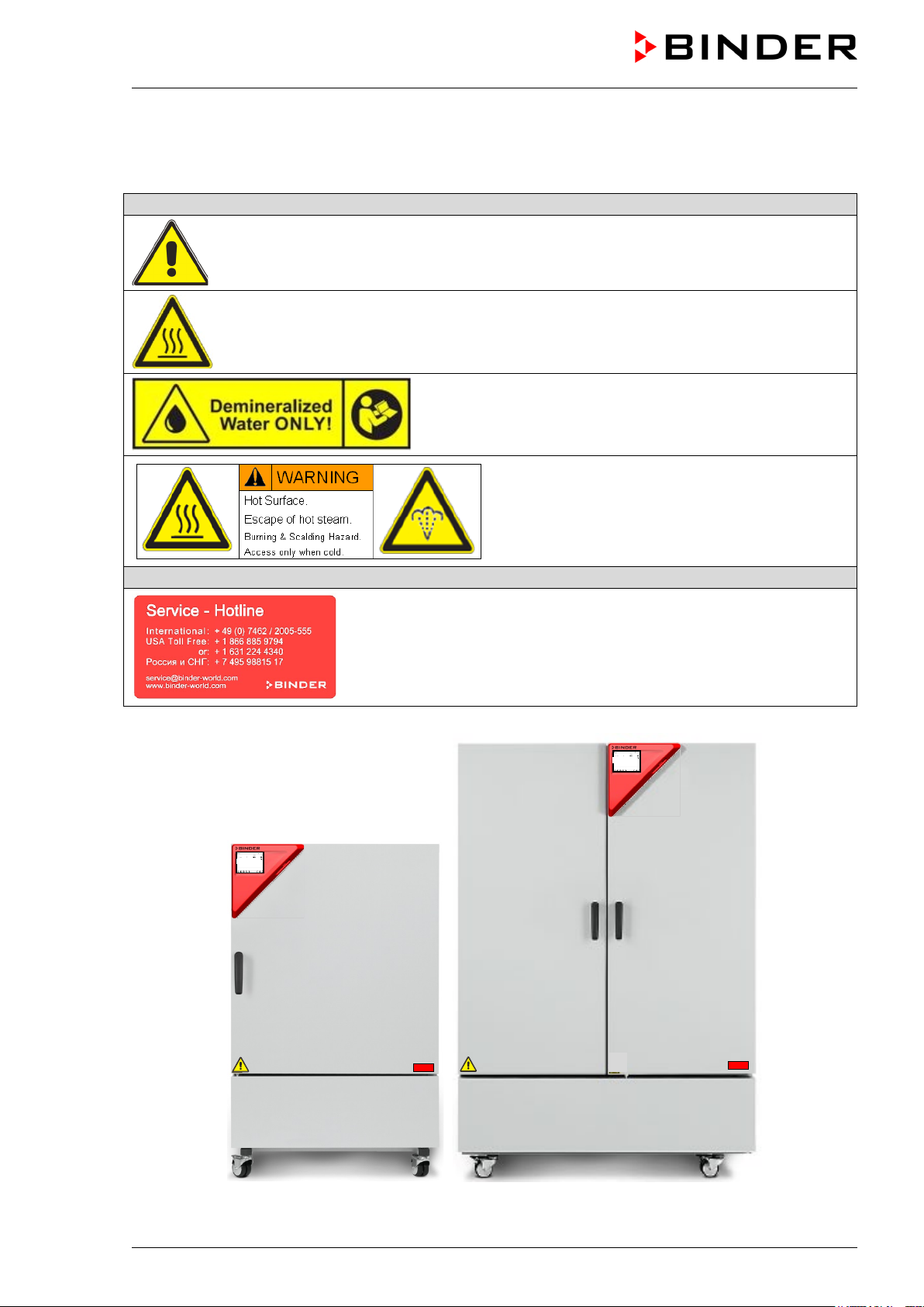
1.5 Localization / position of safety labels on the chamber
The following labels are located on the chamber:
Risk of injury (on outer door, only KBF-UL and KMF-240V).
Observe the safety instructions in the operating manual.
Hot surface (inner glass door above the glass door handle)
Observe the prescribed freshwater quality
(next to water inlet on the rear of the chamber;
on the optional freshwater can)
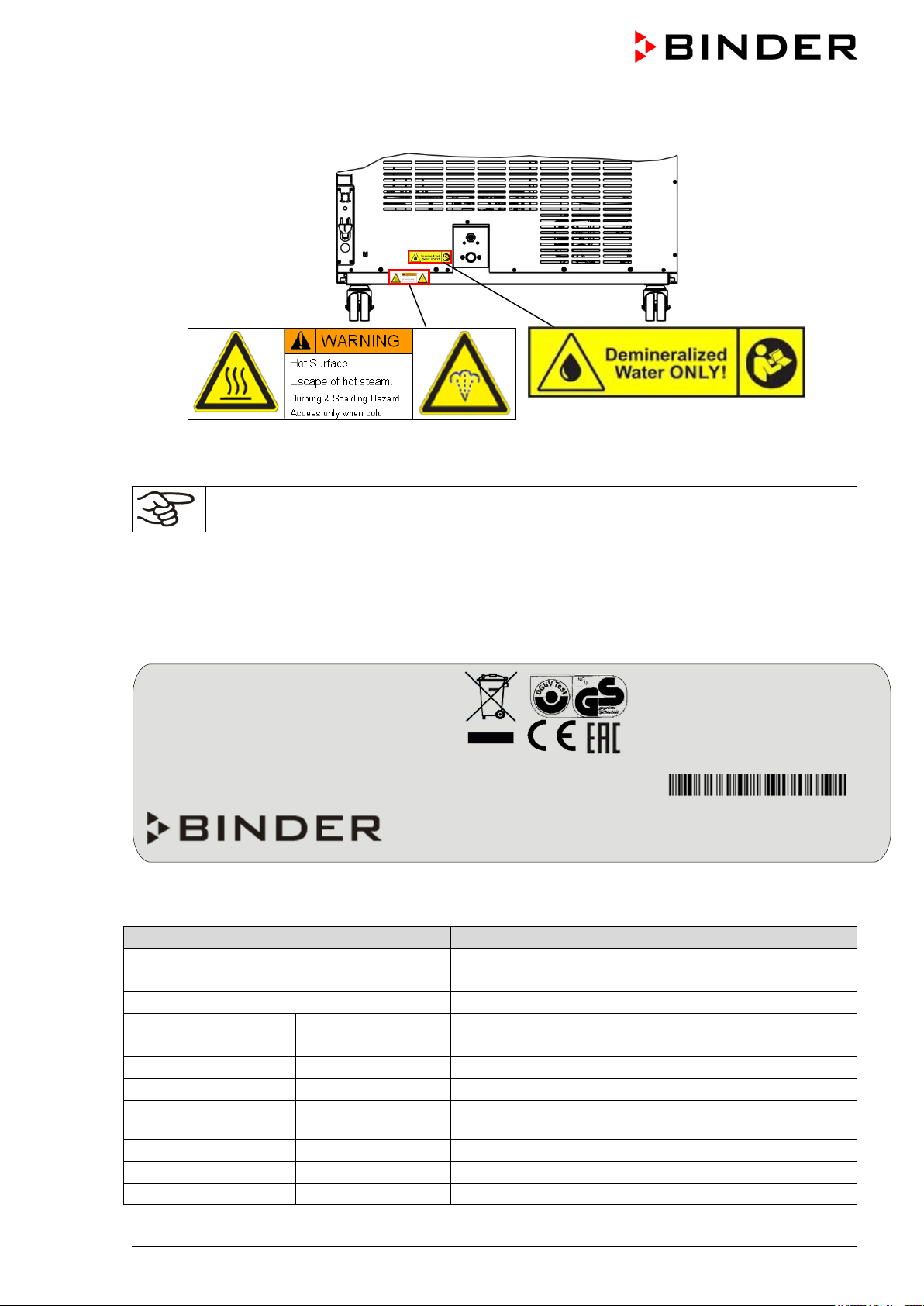
Burning and scalding hazard (chamber rear)
KBF / KBF-UL + KMF (E6) 04/2020 page 10/163
Figure 1: Position of labels on the chamber front (KBF-UL and KMF-240V)
Indications of the type plate (example)
Information
BINDER
Manufacturer: BINDER GmbH
KBF 240
Model designation
Constant climate chamber
Device name
Serial No.
00000000000000
Serial no. of the chamber
Built
2020
Year of construction
Nominal temperature
70 °C / 158 °F
Nominal temperature
IP protection
20
IP type of protection acc. to standard EN 60529
Temperature safety device acc. to standard DIN
12880:2007
Class
3.1
Class of temperature safety device
Art. No.
9020-0322
Art. no. of the chamber
Project No.
---
Optional: Special application acc. to project no.
Nominal temp.
70 °C
2,10 kW / 9,5 A
Max. operating pressure 15 bar
158 °F
200-230 V / 50 Hz
R 134A – 0,17 kg
IP protection
20
200-230 V / 60 Hz
Contains fluorinated
Safety device
DIN 12880
1 N ~
greenhouse gases covered
Class
3.1 by the Kyoto Protocol
Art. No.
9020-0322
Project No.
Built
2020
Constant climate chamber
BINDER GmbH
www.binder-world.com
KBF 240
Serial No. 00000000000000
Figure 2: Position of labels on the chamber rear
Keep safety labels complete and legible.
Replace safety labels that are no longer leg ib le. Cont ac t BINDER Ser vice for these replacements.
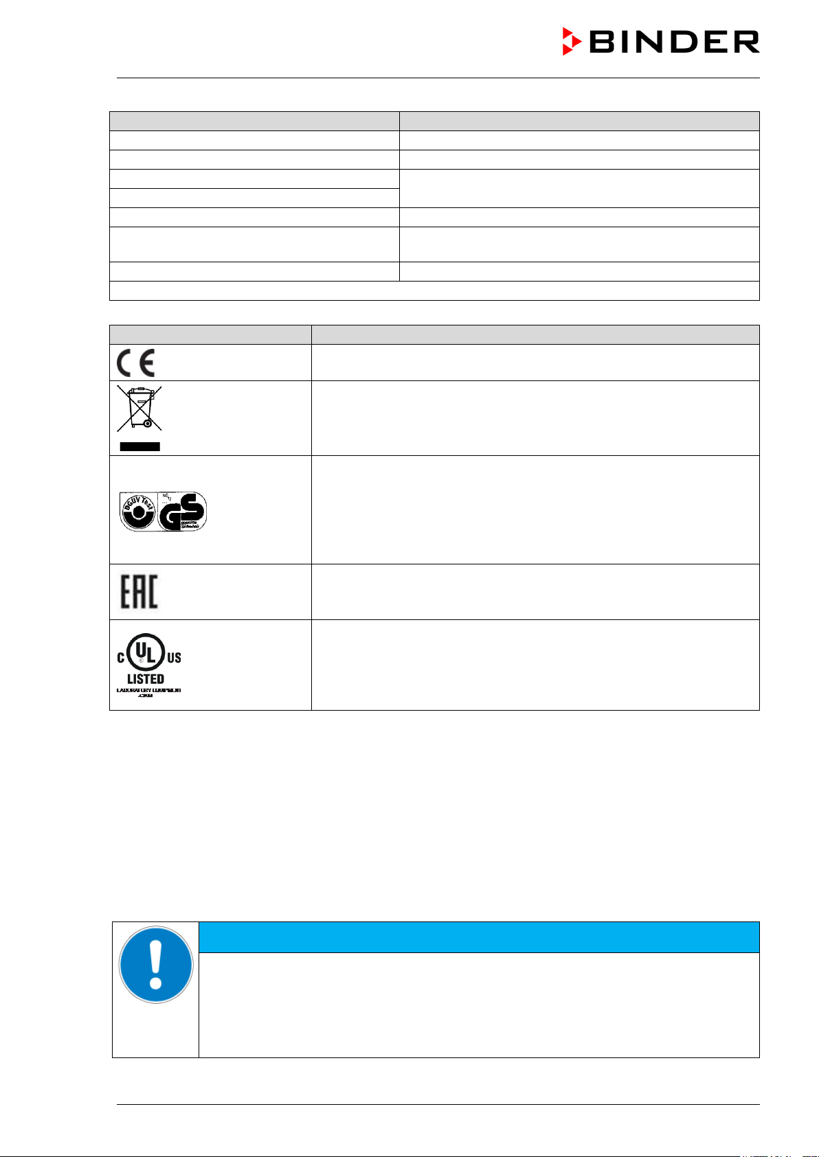
1.6 Type plate
The type plate sticks to the left side of the chamber, bottom right-hand.
Im Mittleren Ösch 5
78532 Tuttlingen / Germany
E6
Figure 3: Type plate (example KBF 240 regular chamber 9020-0322)
Made in Germany
Temp. safety device DIN 12880
KBF / KBF-UL + KMF (E6) 04/2020 page 11/163
Indications of the type plate (example)
Information
2,10 kW
Nominal power
9,5 A
Nominal current
200-230 V / 50 Hz
200-230 V / 60 Hz
1 N ~
Current type
Max operating pressure in the refrigerating system
(15 bar / 218 PSI)
R 134A - 0,17 kg
Refrigerant type and filling weight
Contains fluorinated greenhouse gases covered by the Kyoto Protocol
Symbol on the type plate
Information
Nominal voltage range +/-10%
at the indicated power frequency
Max. operating pressure 15 bar
CE conformity marking
Electrical and electronic equipment manufactured / placed on the mar-
ket in the EU after 13 August 2005 and be disposed of in separate
collection according to Directive 2012/19/EU on waste electrical and
electronic equipment (WEEE).
GS mark of conformity of the “Deutsche Gesetzliche Unfallversicherung e.V. (DGUV), Prüf- und Zertifizierungsstelle Nahrungsmittel und
Verpackung im DGUV Test“ (German Social Accident Insurance
(DGUV), Testing and Certification Body for Foodstuffs and Packaging
Industry in DGUV Test).
(Not valid for UL chambers)
The chamber is certified according to Customs Union Technical Regu-
lation (CU TR) for the Eurasian Economic Union (Russia, Belarus,
(UL chambers
only)
Armenia, Kazakhstan Kyrgyzstan).
The chamber is certified by Underwriters Laboratories Inc.
to the following standards:
rd
• UL 61010-1, 3
• CAN/CSA-C22.2 No. 61010-1, 3
Edition, 2012-05, Rev. 2015-07
rd
Edition, 2012-05, Rev. 2015-07
®
according
1.7 General safety instructions on installing and operating the chambers
With regard to operating t he chambers and to the inst allation location, please ob serve the DGUV guidelines 213-850 on safe work ing in laborat ories, issue d by the em ployers’ liabil ity insuranc e associat ion (for
Germany).
BINDER GmbH is only respons ible for the safety feat ures of the chamber provided sk illed electricians or
qualified personnel authorized by BIND ER perform all m aintenance and repair, and if com ponents relating to chamber safety are replaced in the event of failure with original spare parts.
To operate the chamber, use only original BINDER ac cessories or ac cessories f rom third-par ty suppliers
authorized by BINDER. The user is responsible for any risk caused by using unauthorized accessories.
Danger of overheating due to lack of ventilation.
Damage to the chamber.
∅ Do NOT install the chamber in unventilated recesses.
Ensure sufficient ventilation for dispersal of the heat.
Observe the prescribed minimum distances when installing the chamber (chap. 3.4)
KBF / KBF-UL + KMF (E6) 04/2020 page 12/163
NOTICE
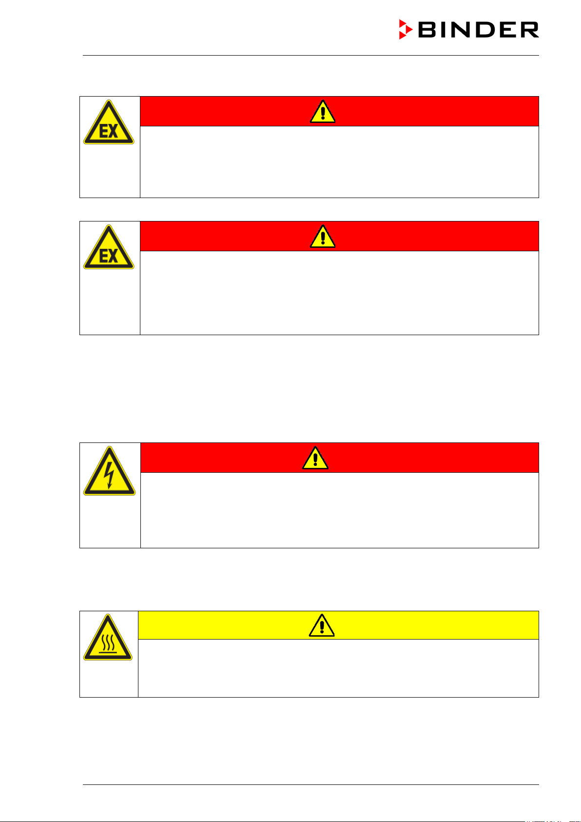
Do not install or operate the chamber in hazar dous lo c ations .
DANGER
Danger of explosion due to combustible dusts or explosive mixtures in the vicinity
of the chamber.
Serious injury or death from burns and / or explosion pressure.
∅ Do NOT operate the chamber in potentially explosive areas.
KEEP combustible dust or air-solvent mixtures AWAY from the chamber.
The chamber does not dispose of any measures of explosion protection.
DANGER
Danger of explosion due to introduction of flammable or explosive substances in
the chamber.
Serious injury or death from burns an d / or explosion pressure.
∅ Do NOT introduce any substance into the chamber which is combustible or explosive at
working temperature.
∅ Do NOT introduce any combustible dust or air-solvent mixture in the inner chamber.
Any solvent contained in the loading material m ust not be explosive or inflamm able. I.e., irrespective of
the solvent concentrati on in the steam room, NO explosi ve mixture with air must f orm. The temperature
inside the chamber mus t lie below the flash point or below the sublim ation point of the loading material.
Familiarize yourself with t he physical and c hemical pr operties of the loading m aterial, as well as the contained moisture constituent and its behavior with the addition of heat energy and humidity.
Familiarize yourself with an y potent ia l health r isk s caused b y the loading material, the cont ained m ois ture
constituent or by reaction products that may arise during the temperature process. Take adequate
measures to exclude such risks prior to putting the chamber into operation.
DANGER
Electrical hazard by water entering the chamber.
Deadly electric shock.
∅ The chamber must NOT become wet during operation, cleaning, or maintenance.
∅ Do NOT install the chamber in damp areas or in puddles.
Set up the chamber in a splash-proof manner.
The chambers were produced in accor dance with VDE regulations and were routinely tested in acc ordance to VDE 0411-1 (IEC 61010-1).
During and shortly after operation, th e tem perature of the in ner surfac es alm ost equals the set -point. The
glass doors, the glass door handles, and the inner chamber will become hot during operation.
CAUTION
Danger of burning by touching hot chamb er p arts during operation.
Burns.
∅ Do NOT touch the inner surfaces, the glass doors or the loading material during opera-
tion.
KBF / KBF-UL + KMF (E6) 04/2020 page 13/163
WARNING
Danger of injury and damages by the chamber tipping over or breakaway of the protruding lower housing cover.
Injuries and damage to the chamber and the loading material
∅ Do NOT load the lower housing cover with heavy objects while the chamber door is
open and do NOT climb on it.
1.8 Intended use
Following the instructions in this operating manual and conducting regular maintenance work
(chap. 20) are part of the intended use.
Any use of the chambers that does not comply with the requirements specified in this Operating
Manual shall be considered improper use.
Other applications than those described in this chapter are not approved.
Use
Constant climate chambers series KBF / KBF-UL and KMF are su ita ble for exact conditioning of har mless
materials.
Requirements for the chamber load
Any solvent must not be e xplosive and flammable. A m ixture of any component of the loading material
with air must NO T be explosive. The operatin g temperature mus t lie below the flash point or below the
sublimation point of the loading material. Any component of the loading material mus t NOT be able to
release toxic gases.
The loading m aterial shall not contain an y corrosive ingredients that may dam age the machine components made of stainless steel, aluminum, and copper. Such ingredients include in particular acids and
halides. Any corrosive damage caused by such ingredients is excluded from liability by BINDER GmbH.
The chamber does not dispose of any measures of explosion protection.
DANGER
Explosion or implosion hazard and danger of poisoning through the introduction of
unsuitable loading material.
Poisoning. Serious injury or death from burns and / or explosion pressure.
∅ Do NOT introduce any substance combustible or explosive at working temperature into
the chamber, in particular no energy sources such as batteries or lithium-ion batteries.
∅ NO explosive dust or air-solvent mixture in the inner chamber.
∅ Do NOT introduce any substance which could lead to release of toxic gases.
Contamination of the chamber by toxic, infectious or radioactive substances must be prevented
WARNING
Danger of intoxication and infection through contamination of the chamber with
toxic, infectious or radioactive substances.
Damages to health.
Protect the interior of the chamber from contamination by toxic, infectious or radioactive
substances.
Take suitable protective measures when introducing and removing toxic, infectious or
KBF / KBF-UL + KMF (E6) 04/2020 page 14/163
radioactive material
In case of foreseeable use of the chamber there is no risk for the user through the integration of the
chamber into systems or by special environmental or operating conditions in the sense of EN 610101:2010. For this, the intended use of the chamber and all its connections must be observed.
Medical devices
The chambers are not classified as medical devices as defined by the Medical Device Directive
93/42/EEC.
Due to the special demands of the Medical Device Directive (MDD), these chambers are not
qualified for sterilization of medical devices as defined by the directive 93/42/EWG.
Personnel Requirements
Only trained personne l with k nowledge of the Operat ing Manua l can s et up and install the c ham ber, start
it up, operate, clea n, and take it out of operation . Service and repairs call for further technical requirements (e.g. electrical know-how), as well as knowledge of the service manual.
Installation site requirements
The chambers are designed for setting up inside a building (indoor use).
The requirements desc ribed in the Operating Manu al for installation site and ambient conditions (Chap.
3.4) must be met.
WARNING: If customer should use a BINDER chamber running in non-supervised continuous operation, we strongly recommend in case of inclusion of irrecoverable specimen or
samples to split such specimen or samples and store them in at least two chambers, if this is
feasible.
1.9 Foreseeable Misuse
Other applications than those described in chap. 1.8 are not approved.
This expressly incl udes the following misuses (t he list is not exhaustive), which pos e risks despite the
inherently safe construction and existing technical safety equipment:
• Non-observance of Operating Manual
• Non-observance of information and warnings on the chamber (e.g. control uni t messages, safety iden-
tifiers, warning signals)
• Installation , startup, operation, maintenance and re pair by untrained, insufficiently qualified, or una u-
thorized personnel
• Missed or delayed maintenance and testing
• Non-observance of traces of wear and tear
• Insertion of materials excluded or not permitted by this Operating Manual.
• Non-compliance with the admissible parameters for processing the respective material.
• Installation, testing, service or repair in the presence of solvents
• Installation of replacement parts and use of accessories and operating r esources not specified and
authorized by the manufacturer
• Installation , startup, operati on, maintenance or repair of the cham ber in absence of operating instruc-
tions
• Bypassing or c hang in g pr ot ec tive systems, operation of the c hamber without the designated protec t iv e
systems
• Non-observance of messages regarding cleaning and disinfection of the chamber.
• Spilling wat er or clean ing agent on the cham ber, water penetrating into the cham ber duri ng operat ion,
cleaning or maintenance.
KBF / KBF-UL + KMF (E6) 04/2020 page 15/163

• Cleaning activity while the chamber is turned on.
• Operation of the chamber with a damaged housing or damaged power cord
• Continued operation of the chamber during an obvious malfunction
• Insertion of objects, particularly metallic objects, in louvers or other openings or slots on the chamber
• Human error (e.g. insufficient experience, qualification, stress, exhaustion, laziness)
To pr event these and other risks from incorrect operati on, the operator sha ll issue operat ing instruct ions.
Standard operating procedures (SOPs) are recommended.
1.10 Residual Risks
The unavoidable design f eatures of a chamber, as well as its proper f ield of application, can also pose
risks, even during corr ect operation. These residual risk s include hazards which, despite the inher ently
safe design, existing technical protective equipment, safety precautions and supplementary protective
measures, cannot be ruled out.
Messages on the chamber and in the Operating Manual warn of residual risks. The consequences of
these residual risk s and the m easures required to prevent them ar e listed in th e Operati ng Manu al. Mor eover, the operator must take measures to minimize hazards from unavoidable residual risks. This includes, in particular, issuing oper ating ins tr ucti ons .
The following list s ummarizes the hazards against which this O perating Manual and the Service Man ual
warn, and specifies protective measures at the appropriate spots:
Unpacking, Transport, Installation
• Sliding or tilting the chamber
• Setup of the chamber in unauthorized areas
• Installation of a damaged chamber
• Installation of a chamber with damaged power cord
• Inappropriate site of installation
• Missing protective conductor connection
Normal operation
• Assem bly errors
• Contact with hot surfaces on the housing
• Contact with hot surfaces in the interior and inside of doors
• Emission of non-ionizing radiation from electrical operating resources
• Contact with live parts in normal state
Cleaning and Decontamination
• Penetration of water into the chamber
• Inappropriate cleaning and decontamination agents
• Enclosure of persons in the interior
Malfunction and Damage
• Continued oper at ion of the c hamber during an obvious malf unc tion or out age of t h e heating, cooling or
humidification system
• Contact with live parts during error status
• Operation of a unit with damaged power cord
KBF / KBF-UL + KMF (E6) 04/2020 page 16/163
Maintenance
• Maintenance work on live parts.
• Execution of maintenance work by untrained/insufficiently qualified personnel
• Electrical safety analysis during annual maintenance not performed
Trouble-shooting and Repairs
• Non-observance of warning messages in the Service Manual
• Trouble-shooting of live parts without specified safety measures
• Absence of a plausibility check to rule out erroneous inscription of electrical components
• Performance of repair work by untrained/insufficiently qualified personnel
• Inappropriate repairs which do not meet the quality standard specified by BINDER
• Use of replacement parts other than BINDER original replacement parts
• Electrical safety analysis not performed after repairs
1.11 O perating instructions
Depending on the a pplicati on and l ocation of the chamber, the operator of the c ham ber must prov ide the
relevant information for safe operation of the chamber in a set of operating instructions.
Keep these operating instructions with the chamber at all times in a place where they are
clearly visible. They must be comprehensible and written in the language of the employees.
KBF / KBF-UL + KMF (E6) 04/2020 page 17/163

1.12 Measures to prevent accidents
The operator of the chamber must observe the following rule: “Betreiben von Arbeitsmitteln. Betreiben
von Kälteanlagen, W ärmepumpen und Kühleinrichtungen“ (Operation of work equipment. Operation of
refrigeration systems, heat pumps and refrigeration equipment) (GUV-R 500 chap. 2.35) (for Germany).
The manufacturer took the follo wing m easur es to prevent ign iti on and expl os io ns:
• Indications on the type plate
See operating manual chap. 1.6.
• Operating manual
An operating manual is available for each chamber.
• Overtemperature monitoring
The chamber is equipped with a temperature display, which can be read from outside.
The chamber is equipped with an addition al saf ety contr oller (tem per ature saf et y device class 3.1 acc .
to DIN 12880:2007). Visual and audible (buzzer) signals indicate temperature exceeding.
• Safety, measurement, and control equipment
The safety, measuring, and control equipment is easily accessible.
• Electrostatic ch arg e
The interior parts are grounded.
• Non-ionizing radiation
Non-ionizing radiatio n is not intentionall y produced, but release d only for technical r easons by electrical equipment (e.g. electric motors, power c ables, solenoids). The m achine has no permanent m agnets. If persons with ac tive im plants (e.g . pac em akers , defibrill ators) keep a saf e dis tance (dist ance of
field source to implant) of 30 cm, an influence of these implants can be excluded with high probability.
• Protection against touchable surfaces
Tested according to EN ISO 13732-1:2008.
• Floors
See operating manual chap. 3.4 for correct installation
• Cleaning
See operating manual chap. 21.4.
• Examinations
The chamber has been inspected by the “Deutsche Gesetzliche Unfallversicherung e.V. (DGUV)
(German Social Accident Insurance (DGUV)” (German Social Accident Insurance (DGUV), Testing
and Certification Body for Foods tuffs and Pac kaging Indus try in DGU V Test) and bears the G S mark .
(Not valid for UL chambers)
®
UL chambers only: The chamber is certified by Underwriters Laboratories Inc.
standards UL 61010-1 , 3
rd
Edition, 2012-05, Rev. 201 5-07; CAN/C SA-C22.2 No. 61010-1, 3rd Edition,
according to the
2012-05, Rev. 2015-07.
KBF / KBF-UL + KMF (E6) 04/2020 page 18/163
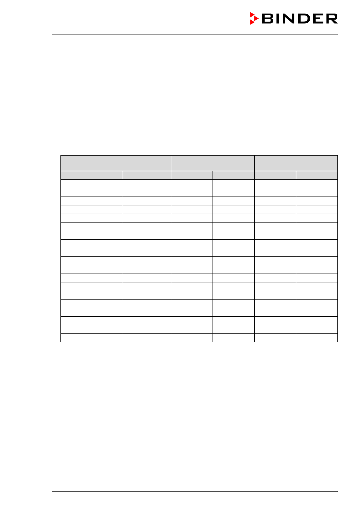
Maximum work place
threshold limit value
Tolerated concentration
with permanent load
Substance
Formula
ppm
mg/m3
ppm
mg/m3
Ammonia
NH3
20
14
5500
4000
Acetone
CH3COCH3
500
1200
3300
8000
Benzene
300
1200
150000
Chlorine
Cl2
0.5
1.5
0.7
2
Acetic acid
CH3COOH
10
25
800
2000
Ethyl acetate
CH3COOC2H5
400
1400
4000
15000
Ethanol
C2H5OH
500
960
3500
6000
Ethylene glycol
HOCH2CH2OH
10
26
1200
3000
Formaldehyde
HCHO
0.3
0.37
2400
3000
Isopropanol
(CH3)2CHOH
200
500
4800
12000
Methanol
CH3OH
200
260
3500
6000
Methyl ethyl ketone
C2H5COCH3
200
590
3300
8000
Ozone
O3
0.1
0.2
0.5
1
Hydrochloric acid
HCl 2 3
300
500
Hydrogen sulphide
H2S
10
15
350
500
Nitrogen oxides
NOx
5 9 5
9
Sulphur dioxide
SO2
5
13 5 13
Toluol
C6H5CH3
100
380
1300
5000
Xylene
C6H4(CH3)2
100
440
1300
5000
1.13 Resistance of the humidity sensor against harmful substances
The following list of har mf ul substanc es ref ers onl y to the hum idit y sensor a nd do es not include any other
materials incorporated in the chamber or prohibited substances in relation to explosion protection.
Some gases - especially clean gases - do not have an y influe nce on th e hum idity sensor . Others do have
a very small influence, whereas others may influence the sensor to a larger extent.
• The following g ases do not influence the sensor and the humidity measurem ent: Arg on (Ar), carbon
dioxide (CO
• The follow ing gases do not or to a m inor extent influe nce the sensor and the hum idity measurem ent:
Butane (C
• The following gases do not , or to a minor extent inf luence the s ensor and the humidit y measurement,
provided that the indicated loads are not exceeded:
),helium (He), hydrogen (H2), neon (Ne), nitrogen (N2), nitrous oxide (N2O), oxygen (O2)
2
), ethane (C2H6), methane (CH4), natural gas propane (C3H8)
4H10
These values are to be cons idered as approxim ate values. T he sensor resistanc e largely depends o n
the temperature and humidity conditions during the time of exposure to harmful substances. Avoid
simultaneous conde nsation. Tolerated error of m easurement: +/- 2 % r.h. The maximum work place
threshold limit value is one that can be regarded as harmless for humans.
• Vapors of oil and fat are dangerous for the sens or because they may condensate at the s ensor and
thus prevent its function (insulating la yer). For similar reasons it is not possible to measure smoke
gases.
KBF / KBF-UL + KMF (E6) 04/2020 page 19/163

2. Chamber description
The constant c lim ate chambers KBF / KBF -UL and KMF are equip ped with a m ultifunct ional m icropr ocessor display c ontroller with 2-channe l technology for tem perature and humidity plus a digital display accurate to one-tenth of a degr ee resp. 0.1% r.h. W ith its comprehensive program control functions, the display program controller MB2 permits the high precision performance of temperature and humidity cycles.
With its micropr ocessor c ontrolled hum idifying and dehum idifying s ystem the chamber is a high-precision
constant climate chamber.
The KBF / KBF-UL com pletely meets the requirements for climatic chambers of the stipulated stabilit y
and durability tests f or pharmaceutical products: Stability tests acc. to ICH gu ideline CPMP/ICH/2736/ 99
(Q1A)
The KMF com pletely meets the requirements of the stipulated stabilit y and durability tests for industrial
products.
Furthermore, it permits simulating exactl y and ov er l on g per iods constant conditions f or other ap pl ic ati ons
such as sample conditioning for material testing of paper, textiles, plastics, building materials, etc.
The APT.line™ preheating cham ber s ystem guarantee s high le vel of spat ial and tim e-based tem perature
precision, thanks to the direct and distributed air circulat ion into the interior. The fan suppor ts exact attainment and maintenance of the desired temperature accuracy.
Humidity control: A resistance hum idifying system humidifies the air . For this purpose, use deion ized
(demineralized) water. The opti on BINDER Pure Aqu a Service allows using the ch am ber with an y degree
of water hardness.
Material: The inner cham ber, the pre-heating ch amber and the interior side of the doors are all m ade of
stainless steel V2A (German material no. 1.4301, US equivalent AISI 304). The housing is RAL 7035
powder-coated. All corners and edges are also completely coated.
All chamber f unctions are eas y and comf ortable to use th anks to the ir clear arra ngement. Major features
are easy cleaning of all chamber parts and avoidance of undesired contamination.
Controller: T he efficient program controller is equ ipped with a multitude of operating f unctions, in addition to recorder and a larm functions. Progr amming of test c ycles is easily accomplished via the modern
MB2 touch screen controller and is also pos sible directly with a com puter via Intranet in conn ection with
the APT-COM™ 4 Multi Manag ement Software (option, c hap. 19.1). The chamber comes equipped with
an Ethernet serial interf ace for computer communication. In addition, the B INDER APT-COM™ 4 Mult i
Management Software permits networking up to 100 chambers and connecting them to a PC f or controlling and programm ing, as well as recor ding and repres enting temperatur e and humidity dat a. For further
options, see chap.23.6.
The chambers size 240, 720, and 10 20 are equipped with f our castors. Both f ront castors can be easily
locked via the attached brakes.
KBF / KBF-UL: temperature range: 0 °C / 32 °F up to 70 °C / 158 °F, humidity range: 10% r.h. to 80%
r.h.
KMF: temperature range -10 °C / 14 °F up to +100 °C / 212 °F, humidity range: 10 % r.h. to 98 % r.h.
For the control ranges of temperature and humidity, see climatic diagrams (chap. 17).
KBF / KBF-UL + KMF (E6) 04/2020 page 20/163
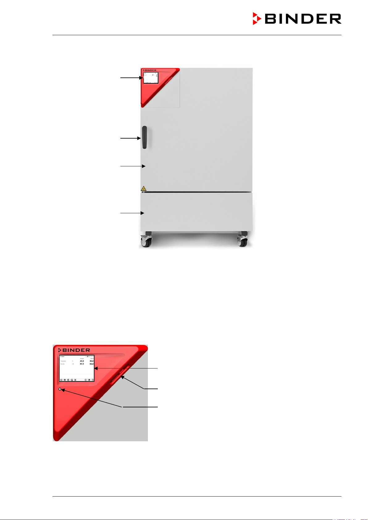
(A)
2.1 Chamber overview
(B)
(C)
(D)
Figure 4: Constant climate chamber KBF / KBF-UL / KMF size 240
(A) Instrument box
(B) Door handle
(C) Outer door
(D) Refrigerating machine and humidity generat ion m odule
2.2 Instrument panel
5,7" controller display with touchscreen
USB interface
Pilot lamp
Figure 5: Instrument panel with MB2 program controller and USB interface
KBF / KBF-UL + KMF (E6) 04/2020 page 21/163
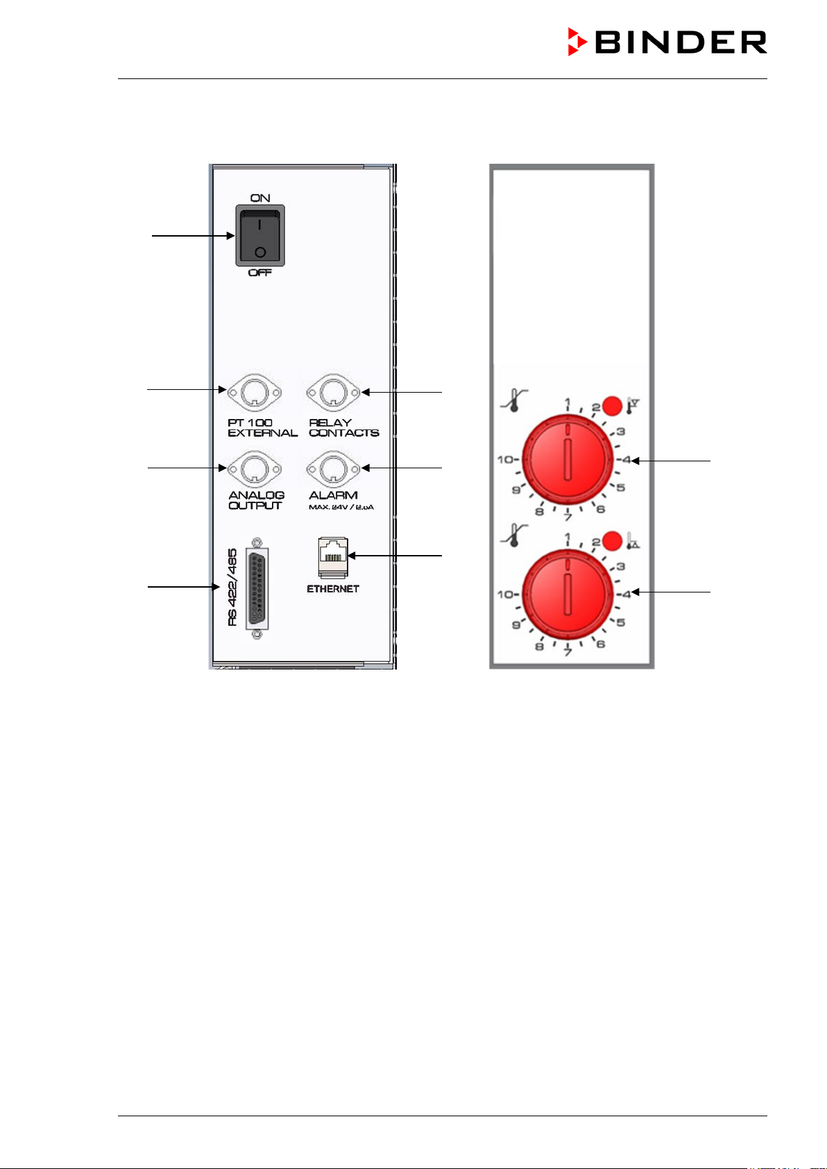
2.3 Lateral control panels
(1)
(2)
(3)
(4)
(5)
(6)
(7)
(8)
(9)
right side left side (optional)
(1) Main power switch
(2) DIN socket for additional Pt 100 sensor (available via BINDER INDIVIDUAL customized solutions)
(3) DIN socket for analog outputs (option)
(4) RS485 interface
(5) DIN socket for switching contacts (option for KMF)
(6) DIN socket for zero-voltage relay alarm output (option)
(7) Ethernet interface
(8) Temperature safety device class 3.1 (part of option “Safety device class 3.3”)
(9) Temperature safety device class 3.2 (part of option “Safety device class 3.3”)
Figure 6: Lateral control panels at the sides of the refrigerating / humidity generation module
with optional equipment
KBF / KBF-UL + KMF (E6) 04/2020 page 22/163
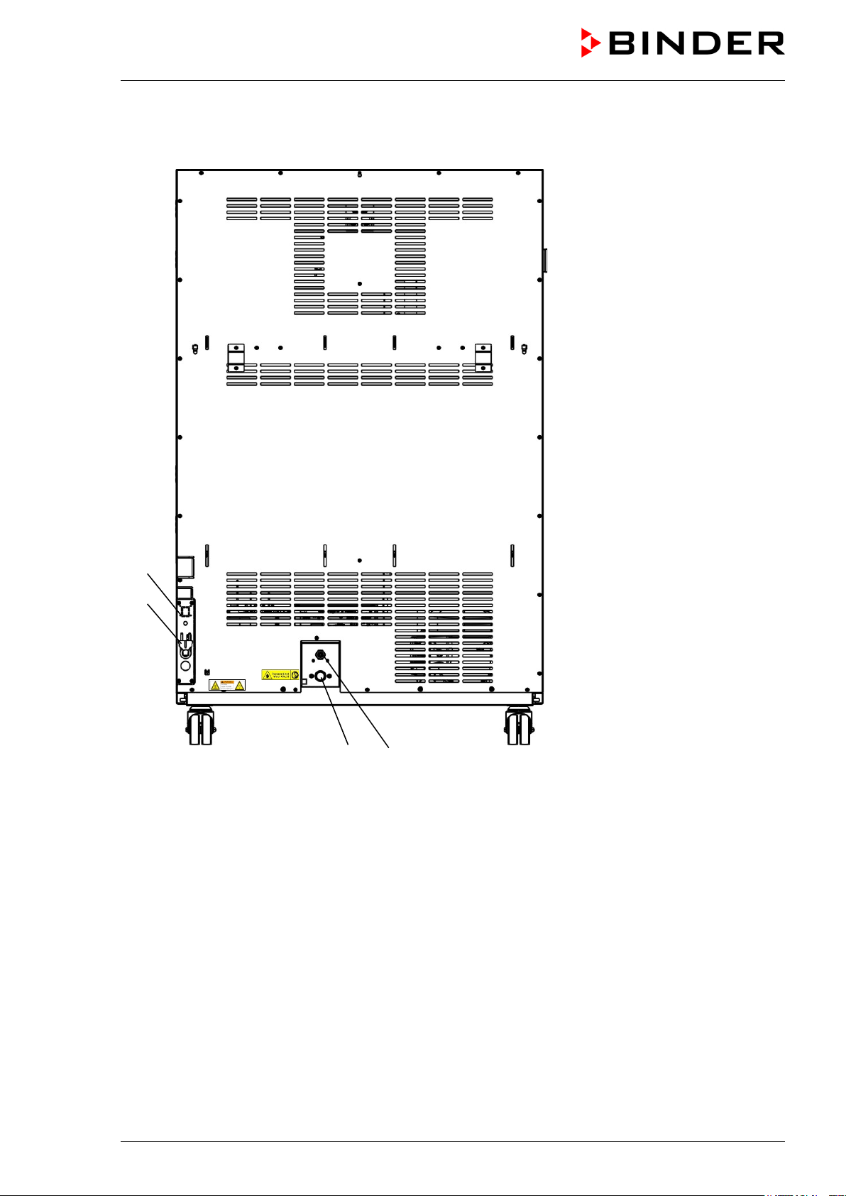
2.4 Rear v iew with water connections
(10)
(11)
(13) (14)
Figure 7: Rear view of the chamber with water connections
(10) Socket for optional freshwater can (chap. 19.9.1)
(11) Power cable
(12) not used
(13) Freshwater connection “IN” with screw thread ¾’’ for hose ½“, with union nut
(14) Wastewater connection “OUT” with hose olive for hose ½“
KBF / KBF-UL + KMF (E6) 04/2020 page 23/163
3. Completeness of delivery, transportation, storage, and installa-
tion
3.1 Unpacking, and checking equipment and completeness of delivery
After unpacking, p lease check the chamber and its optional acc essories, if any, based on the del ivery
receipt for completenes s and for transportation damage. I nform the carrier immediately if transportation
damage has occurred.
The final tests of the manufactur er m a y have caused t rac es of the s helves on the i nner s urfaces. This has
no impact on the function and performance of the chamber.
Please remove an y transportation protection de vices and adh esives in/on th e chamber and on th e doors
and remove the operating manuals and accessory equipment.
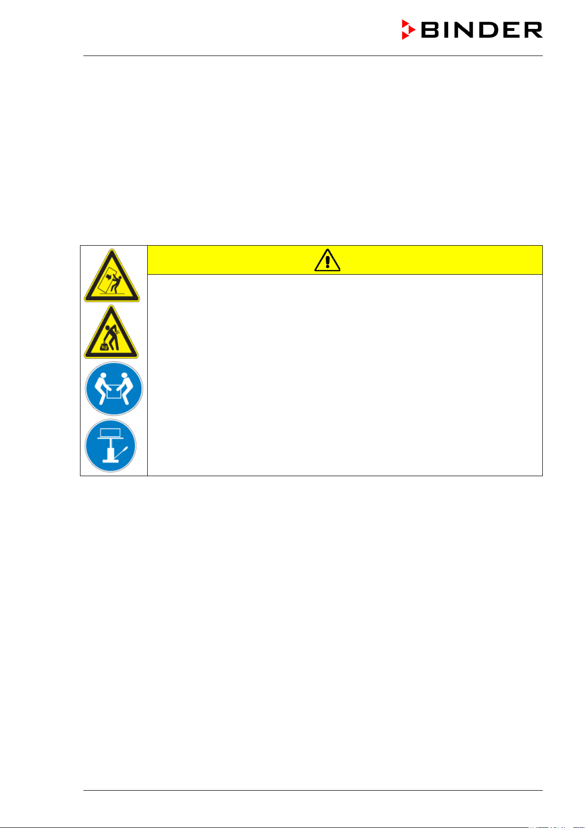
CAUTION
Risk of injury and damages by lifting heavy loads and by sliding or tilti n g o f the
chamber due to improper lifting.
Injuries, damage to the chamber.
∅ Do NOT lift or transport the chamber using the door, the handle, or the lower housing.
Lift chambers size 115 from the pallet at the four lower corners with the aid of four
people
Lift chambers size 240 from the pallet at the four lower corners with the aid of six peo-
ple or with a fork lifter. Set the fork lifter only from the front or rear in the middle of the
chamber.
Lift the chambers sizes 720 and 1020 from the pallet using technical devices (fork
lifter). Set the fork lifter only from the front or rear in the middle of the chamber.
∅ Do NOT set the fork lifter from the chamber side.
If you need to return the chamber, please use the original packing and observe the guidelines for safe
lifting and transportation (chap. 3.2).
For disposal of the transport packing, see chap. 22.1.
Note on second-hand chambers (Ex-Demo-Units):
Second-hand chambers are chambers that were us ed for a short time for tests or exhib itions. They are
thoroughly tested before resale. BINDER ensures that the chamber is technically sound and will work
flawlessly.
Second-hand chambers are marked with a sticker on the chamber door. Please rem ove the stic k er bef or e
commissioning the chamber.
KBF / KBF-UL + KMF (E6) 04/2020 page 24/163
3.2 Guidelines for safe lifting and transportation
The front castor s of the cham bers size 240, 720 and 1020 can be blocked by brakes. After operation,
please observe the guidel ines for temporarily decomm issioning the chamber (chap. 22.2). Please move
the chambers with castors only when em pty and on an eve n surfac e, otherwise the c astors m ay be damaged.
CAUTION
Risk of injury and damages by lifting heavy loads and by sliding or tilti n g o f the
chamber due to improper transportation.
Injuries, damage to the chamber.
Transport the chamber in its original packaging only.
For moving or shipping, secure the constant climate chamber with transport straps.
∅ Do NOT lift or transport the chamber using the door, the handle, or the lower housing.
Lift chambers size 115 at the four lower corners with the aid of 4 people
Lift chambers size 240 at the four lower corners with the aid of 6 people or with a fork
lifter. Set the fork lifter only from the front or rear in the middle of the chamber.
Lift the chambers sizes 720 and 1020 using technical devices (fork lifter). Set the fork
lifter only from the front or rear in the middle of the chamber.
∅ Do NOT set the fork lifter from the chamber side.
You can order transport packing for moving or shipping purposes from BINDER service.
Permissible ambient temperature range during transport:
• If the steam humidifying system has NOT been emptied: +3 °C / 37.4 °F to +60 °C / 140 °F.
• After BINDER Service has emptied the steam humidifying system: -10 °C / 14 °F to +60 °C / 140 °F.
With temperatures below +3 °C / 37.4 °F, water must be com pletely removed f rom the humidifying system.
NOTICE
Danger of freezing in the steam gener ator when transporting the chamber below
+3 °C / 37.4 °F with filled steam humidifying system.
Damage to the chamber.
Contact BINDER Service bef or e any transp ortat ion be l o w +3 °C / 37.4 °F.
3.3 Storage
Intermediate storage of the chamber is possible in a closed and dr y room. Observe the gu idelines for
temporary decommissioning (chap. 22.2).
Permissible ambient temperature range during storage:
• If the steam humidifying system has NOT been emptied: +3 °C / 37.4 °F to +60 °C / 140 °F.
• After BINDER Service has emptied the steam humidifying system: -10 °C / 14 °F to +60 °C / 140 °F
KBF / KBF-UL + KMF (E6) 04/2020 page 25/163
With temperatures be low +3 °C / 37.4 °F, water m ust be completel y removed from the humidif ying system.
NOTICE
Danger of freezing in the steam gener ator when storing the chamber below +3 °C /
37.4 °F with filled steam humidifying system.
Damage to the chamber.
Contact BINDER Service before any storage below +3 °C / 37.4 °F.
Permissible ambient humidity: max. 70 % r.h., non-condensing.
After extensive operati on at hum idity levels > 70% r.h., condensat ion f rom excessive hum idity can lead t o
corrosion during storage. In this case the chamber must first be dried.
NOTICE
Danger of corrosion on the housing due to condensation by excess humidity after
operating at humidity values > 70 % r.h. for a long period.
Damage to the chamber.
Let the chamber dry for several days before shut-down:
• Set the hum idity to 0 % r.h. T o enable dehumidificatio n, the humidifying and d ehumidifying system m ust be activated (d eactivated op eration l ine “Hum idity off”, chap.
7.3 and setting “Control on”, chap. 6.3).
• Set the temperature set point to 60 °C / 140 °F for approx. 2 hours (Manual mode).
• Only then, shu t down the chamber at the main power switch (1) and c lose the tap of
the water supply.
When after storage in a co ld location you transfer the chamber to its warmer installat ion site, condensation may form. Befor e start-up, wait at least one hour u ntil the c ham ber has atta ined am bient tem perat ure
and is completely dry.
In case of a prolonged temporal d ecommissioning: Leave th e chamber door open or rem ove the access
port plugs.
3.4 Location of installation and ambient conditions
Set up the constant c limate chamber on a flat, even surface, and in a well-ventilated, dry location and
align it using a spir it level. The site of installation m ust be capable of supporting the chamber’s weight
(see technical data, chap. 23.5). The chambers are designed for setting up inside a building (indoor use).
NOTICE
Danger of overheating due to lack of ventilation.
Damage to the chamber.
∅ Do NOT install the chamber in unventilated recesses.
Ensure sufficient ventilation for dispersal of the heat.
Observe the prescribed minimum distances when installing the chamber.
Do not install or operate the chamber in potentially explosive areas.
DANGER
Danger of explosion due to combustible dusts or explosive mixtures in the vicinity
of the chamber.
Serious injury or death from burns an d / or explosion pressure.
∅ Do NOT operate the chamber in potentially explosive areas.
KEEP explosive dust or air-solvent mixtures AWAY from the vicinity of the chamber.
KBF / KBF-UL + KMF (E6) 04/2020 page 26/163
Ambient conditions
• Permiss ible ambient tem perature r ange dur ing oper ation: +18 °C / 64.4 °F to +32 °C / 89.6 °F. At ele-
vated ambient temperature values, fluctuations in temperature can occur.
The ambient temperature should not be substantially higher than the indicated ambient temperature of +22 °C +/- 3 °C / 71.6 °F +/- 5.4 °F to which the specified technical data relate.
Deviations from the indicated data are possible for other ambient conditions.
With each degree of ambient temperature >25 °C / 77 °F, the refrigeration power decreases
by 1.5 K.
• Permissible ambient humidity: 70 % r.h. max., non-condensing
When operating the cham ber at tem perature s et-po ints belo w am bient tem peratu re, hig h am bient hum idity may lead to condensation on the chamber.
• Installation height: max. 2000 m / 6562 ft. above sea level.
Distances
• When placing se veral chambers of the same size side by side, m aintain a minimum distance of 250
mm / 9.84 in between each chamber.
• Wall distances: rear 100 mm / 3.9 in, sides 160 mm / 6.29 in.
• Spacing above the chamber of at least 100 mm / 3.9 in must also be accounted for.
NOTICE
Danger by stacking.
Damage to the chambers.
∅ Do NOT place the chambers on top of each other.
Other requirements
A water tap (1 bar to 10 bar) is nec es sary for the installation of the hum idif icati on s ystem (chap. 4.3). If no
suitable in-house water c onnection is available, you can manuall y supply water by filling the freshwater
can (option, chap. 19.9).
To avoid any possible water damage, provide a floor drain at the location of the device. Select
a suitable installation site to avoid any consequential damage by splashing water.
To completely separat e the chamber f rom the power supp ly, you mus t disconnect the power plug . Install
the chamber in a way that the power plug is easily accessible and can be easily pulled in case of danger.
For the user there is no risk of temporary overvoltages in the sense of EN 61010-1:2010.
With an increased amount of dust in the ambient air, clean the c on denser fan (by suction or blowing) sev-
eral times a year.
Avoid any conducti ve dust in the ambiance accor ding to th e chamber layout com plying with pollution de-
gree 2 (IEC 61010-1).
After turning off the chamber, you must close the tap of the water suppl y. Install the chamber in a way
that the freshwater supply is easily accessible.
With option “Extern al freshwater and wastewater can s” (chap. 19.9): Install the chamber in a way that
freshwater can is easily accessible for filling.
KBF / KBF-UL + KMF (E6) 04/2020 page 27/163
4. Installation and connections
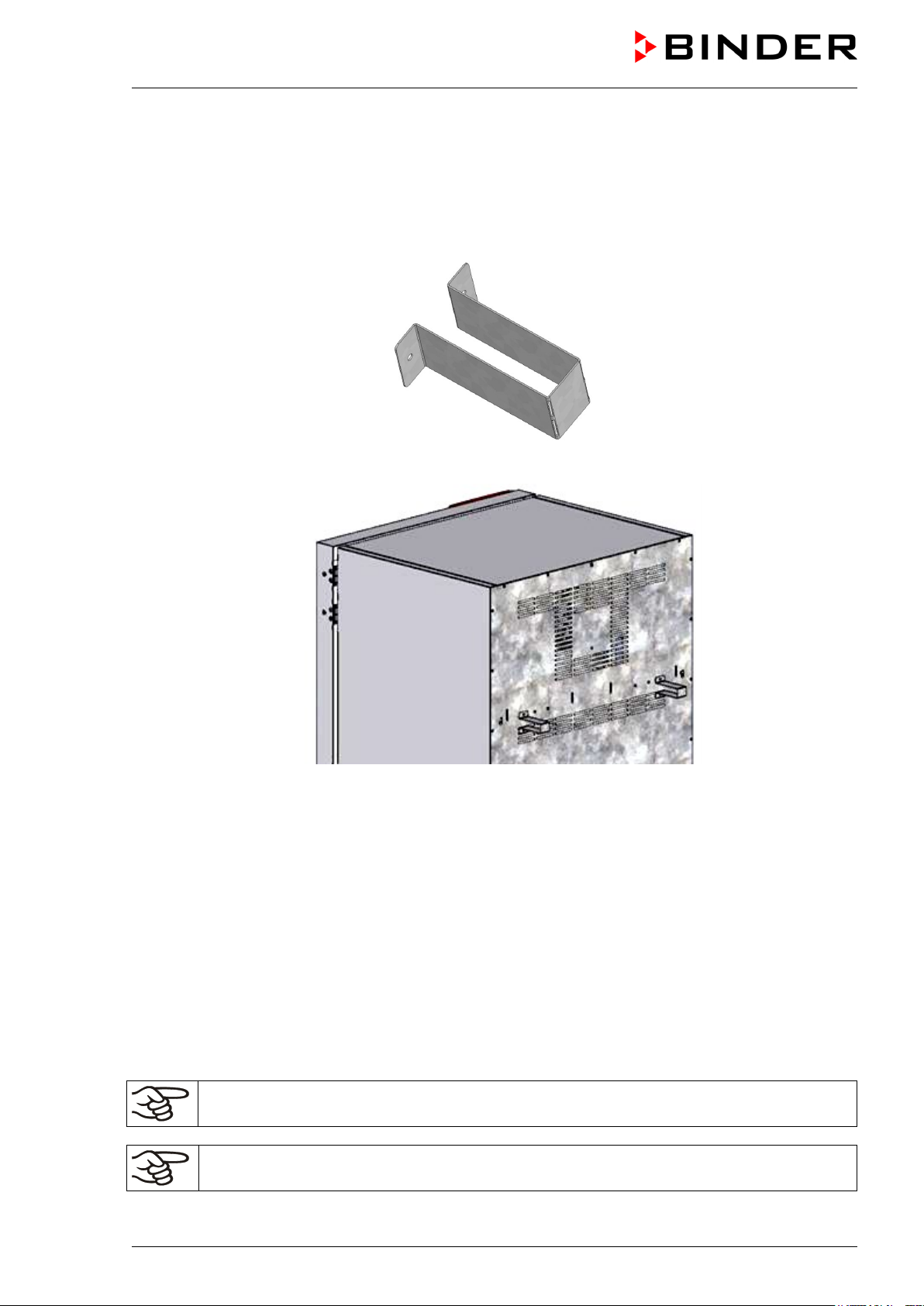
4.1 Spacer for wall distance
Please fix both spacers with the supplied screws at the chamber rear. This serves to ensure the prescribed minimum distance to the rear wall of 100 mm / 3.94 in.
Figure 8: Spacer for wall distance
Figure 9: Chamber rear with mounted spacers
4.2 Wastewater connection
Fasten the wastewater hos e to the wastewater connection “OUT” (14) on the rear of the chamber (olive ∅
14 mm). Observe the following points:
• You can use a part of the supplied water hose as a drainage hose. In case another hose is used, it has
to be permanently resistant against at least 95 °C / 203 °F.
• Mount the waste water hose with a m axim um pos itive inclinat ion of 1 m and a m ax im um total length of
3 m.
• Protect the chamber end of the drainage hose with one of the supplied hose clamps.
• Reliably preve nt sucking back of wastewater. The end of the wastewater hose m ust not be imm ersed
in liquids. This can be ensured e.g., by free discharge.
Wastewater is collected in an internal can with a volume of approx. 0.5 liters. It is pumped off
only when required, thus there is no continuous wastewater flow.
Protect the wastewater supply with the supplied hose clamps.
KBF / KBF-UL + KMF (E6) 04/2020 page 28/163
4.3 Freshwater supply
Connect the wastewater pipe before connecting the chamber to a freshwater pipe or filling the
freshwater can (option, chap. 19.9).
You can supply the chamber with freshwater vi a a water pipe or by manua lly filling a fr eshwater can (option, chap. 19.9).
Water intake temperature NOT below +5 °C / 41 °F and not exceeding 40 °C / 104 °F.
NOTICE
Danger of calcification of the humidify ing system.
Damage to the chamber.
Operate the chamber with deionized (demineralized) water only.
Types of suitable water quality:
• Deionized water f rom a wat er treatm ent insta llation alr ead y existing at t he cus tomer 's site. Con ductiv ity from 1 µS /cm up to a max im um of 20 µS/c m . (Water, which is in equilibrium with the CO
and has a conductivity below 1 µS/cm (ultrapure water), may cause acid corrosion due to its low pH).
in the air,
2
• Water treated by the optional water treatment system BINDER Pure Aqua Service (disposable system). A reusable measuring equipment to assess the water quality is included (chap. 19.10).
BINDER GmbH is NOT responsible for the water quality at the user’s site.
Any problems and malfunctions that might arise following use of water of deviating quality are
excluded from liability by BINDER GmbH.
The warranty becomes void in the event of use of water of deviating quality.
4.3.1 Automatic freshwater supply via water pipe
An enclosure inside th e chamber contains the conne ction kit for freshwater and wastewater . Install the
freshwater connection using either the enclosed water hose or another pressure-resistant one. To accomplish this, remove the cover of the freshwater conn ec tion “I N” (13) on the rear of the chamber. Protect
both ends of the hose with two of the four supplied hose clamps.
Before turnin g on the chamber, check the connection f or leak s. Water supply is automat icall y effec ted via
the freshwater connection “IN” (13).
As the appliance only lets in water when required, there is no continuous water flow.
• Supply pressure 1 to 10 bar when connecting to a water pipe
• Water type: deionized (demineralized) water
• Water intake temperature NOT below +5 °C / 41 °F and not exceeding 40 °C / 104 °F.
• The water intake should be provided with a shut-off slide or water-tap.
• For the water supp ly, fix the delivered adapter with hose olive on the thread at th e rear of
the chamber.
• Protect the water supply at one side with the supplied hose clamp.
KBF / KBF-UL + KMF (E6) 04/2020 page 29/163
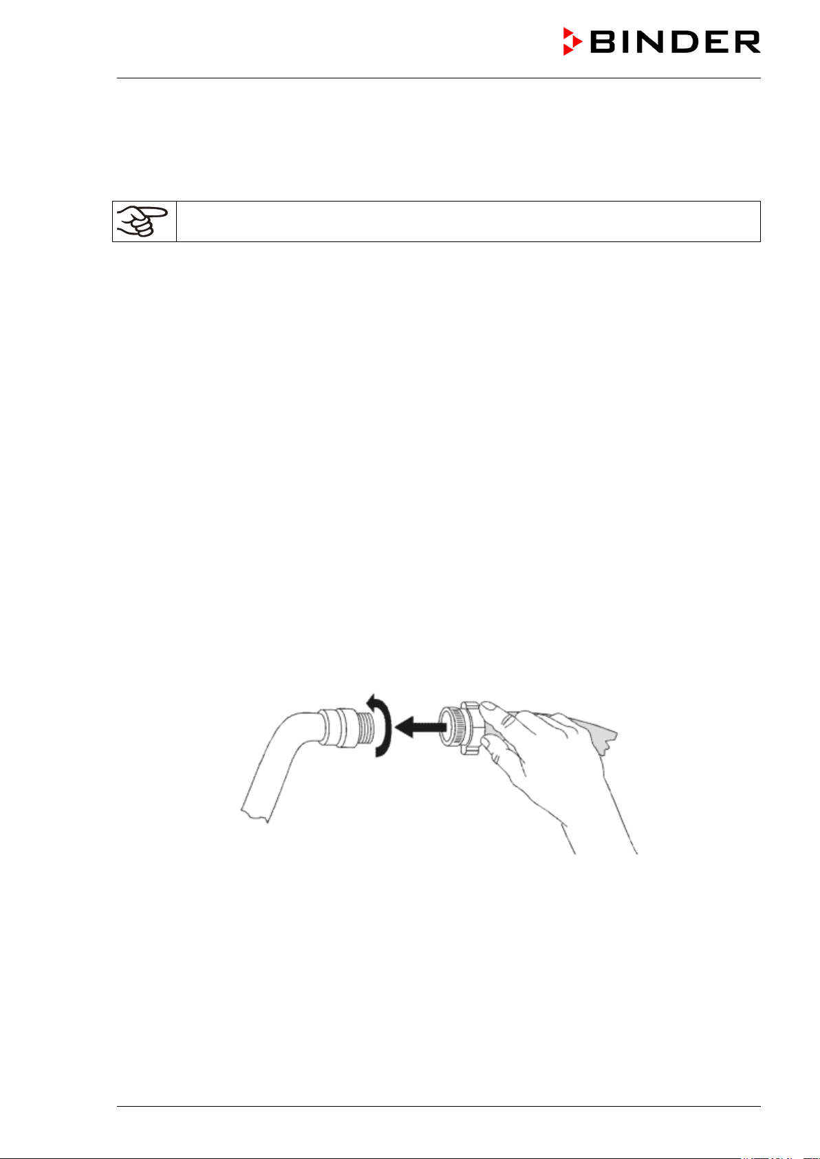
4.3.2 Manual freshwater supply via external freshwater can (option)
If no house water connecti on with suitable water is available, you can manually supply water by filling a
freshwater can (optio n, vo lum e: 20 liter s / 0.71 cu.ft. You can attach the f resh water c an on t he re ar of the
chamber or place it next to the chamber (chap. 19.9).
To guarantee humidification during 24 hours even at high humidity set-points with manual
water supply, we recommend filling the freshwater can (option) daily at the end of the day.
4.3.3 Connection kit for connecting the chamber to the wat er main
A safety kit agai nst floodi ng cause d by bur st water hoses is enclosed with the constant climate chamber.
It consists of the following:
• Hose burst protection device
• 2 hose nozzles with screwing
• 4 hose clamps
• 6m water hose, divisible for the feed hose and drain
Protection principle of hose burst protection:
Whenever a strong water fl ow of about 18 l / m in. occ urs, e.g. caused by a bur st water hos e, a va lve au-
tomatically cuts off the water supply, which can be heard as a clicking noise. T he water supply now remains shut until it is manually released.
Assembly:
Screw the hose burst protec tion device onto a water tap with a G¾ inch right turning thread c onnection.
The connection is self -sealing. Establish the connecti on between the safety kit and the cham ber with a
part of the supplied hose. Protect both ends of the hose by the supplied hose clamps.
We recommend connectin g the hos e as th e last step in or der to av oi d t wist ing t he hos e while sc r e wing o n
the safety kit.
Open the water tap slowly in order to avoid actuating the hose burst protection device.
Figure 10: Assembly of the connection kit
Release of the reflux protection device:
In case the burst protection device has interru pted the water suppl y, first f ind the reason an d rem ove it as
necessary. Close the wate r tap. Release the valve by a half lef t-turn of the upper knurled part. You can
hear the release of the valve as a c licking nois e. T ighten the burst pr otect ion devi ce against th e water tap
by a right turn. Open the water tap slowly afterwards.
KBF / KBF-UL + KMF (E6) 04/2020 page 30/163

Maintenance of the assembly of the hose burst protection device:
Calcification can im pair valve function. We recommend an a nnual inspection by a skilled plumber. The
plumber should demount the safety kit to check the valve by hand for function, calcification or blockage.
NOTICE
Danger of impairment of the valve function by calcification.
Damage to the chamber.
Have a plumber inspect the valve annually.
Remove calcifications by citric acid or acetic acid solutions.
Continue by testing the function and tightness of the mounted chamber
Check: Quickl y open the water tap while there is n o chamber connected – the valve should cut off the
water flux without any delay.
4.3.4 Safety kit: Hose burst protection device with reflux pr otection device (availabl e via
BINDER INDIVIDUAL customized solutions)
A safety kit with a reflux protec tion device is available for protection of the drink ing water system, and
against flooding caused by burst water hoses.
Protection principles:
Whenever a strong water fl ow of about 18 l / m in. occ urs, e.g. caused by a bur st water hos e, a va lve automatically cuts off the water supply, which can be heard as a clicking noise. The water supply no w remains shut until it is manually released.
A possible endangering of the dr i nking water system depends on th e ris k potent ial of the loading material.
Under unfavorable con ditions (e.g. decreasing pr essure inside the tap water system ), drained-off loading
material could be sucked out of the c ham ber via the steam generator into the tap water system and therefore contaminate the drink ing water. The saf ety kit with reflux protection d evice provides security in cas e
of short-term utilization of substances with low risk potential. W hen using substances bearing a higher
risk potential, install a pipe disconnector to assure absolute protection. It is the user’s responsibilit y to
prevent (according to nat ional standards) an y reflux of contaminated water from getting int o the drinking
water system.
Assembly:
The standard supplied parts – hose burst protection device, hose nozzle with screwing – are not needed.
Screw the pre-mounted as sembly of the hose burst p rotection and ref lux protecti on devices ont o a water
tap with a G¾ inch right tu rning thread connec tion. The connect ion is self-seal ing. Establish the co nnection between the safety kit and the c hamber with a part of the supplied hose. Protect both ends of the
hose with the supplied hose clamps.
We recommend connectin g the hose as the last step in order to avoid twisting it while s crewing on the
safety kit.
Open the water tap slowly in order to avoid actuating the hose burst protection device.
KBF / KBF-UL + KMF (E6) 04/2020 page 31/163

Figure 11: Assembly of the safety kit (hose burst protection and reflux protection devices)
Release of the reflux protection device:
In case the hose burst protection device interru pts the water supply, first find the reason and r em ove it as
necessary. Close the wate r tap. Release the valve by a half lef t-turn of the upper knurled part. You can
hear the release of the valve as a c licking noise . T ighten the burst prot ectio n devi ce against th e water tap
by a right turn. Open the water tap slowly afterwards.
Maintenance of the assembly of hose burst protection and reflux protection devices:
Calcification can impair the function of both valves. We recommend an annual inspection by a skilled
plumber. The plum ber sho uld remove the safet y kit wi th the reflux protectio n devic e to chec k both va lves
by hand for proper function and calcification or blockage.
NOTICE
Danger of impairment of the valve function by calcification.
Damage to the chamber.
Have a plumber inspect the valve annually.
Remove calcifications by citric acid or acetic acid solutions.
Continue by testing the function and tightness of the mounted chamber
Check: Quickl y open the water tap while there is n o chamber connected – the valve should cut of f the
water flux without any delay.
KBF / KBF-UL + KMF (E6) 04/2020 page 32/163

KBF1020-230V
9x20-0326
KBF115UL-240V
KBF 1020UL-240V
9x20-0321
9x20-0327
KMF720-230V
9x20-0345
KMF720-240V
9x20-0346
4.4 Electrical connection
The chambers ar e supplied ready for connection. T hey come with a fixed power c onnection cable of at
least 1800 mm / 70.87 in in length.
Model version
KBF115-230V
KBF240-230V
KBF720-230V
KBF240UL-240V
KBF720UL-240V
KMF115-230V
KMF240-230V
KMF115-240V
KMF240-240V
• The dom estic socket must also prov ide a protective conduc tor. Make sure that the connection of the
protective conductor of the domes tic installat ions to th e cham ber ’s protective c onductor meets the latest technology. The protective conductors of the socket and plug must be compatible!
Art. No.
(x = 0 or 1)
9x20-0320
9x20-0322
9x20-0324
9x20-0323
9x20-0325
9x20-0341
9x20-0343
9x20-0342
9x20-0344
Power plug
Grounded plug
NEMA 6-20P
Grounded plug
NEMA 6-20P
Voltage +/-10% at the
indicated power fre-
quency
200-230 V at 50 Hz
200-230 V at 60 Hz
200-240 V at 50Hz
200-240 V at 60Hz
200-230 V at 50 Hz
200-230 V at 60 Hz
200-240 V at 50Hz
200-240 V at 60Hz
Current
type
1N~ 16 Amp
2~ 16 Amp
1N~ 16 Amp
2~ 16 Amp
Chamber
fuse
DANGER
Electrical hazard due to missing protective conductor connection.
Deadly electric shock.
Make sure that the chamber’s power plug and the power socket match and secure-
ly connect the electrical protective conductors of the chamber and the house installation.
• Prior to con nection and s tar t-up, chec k the power supply voltage. C om pare the values to the s pecif ied
data located on the chamber’s type plate (left chamber side, bottom right-hand, see chap. 1.6).
NOTICE
Danger of incorrect power supply voltage due to improper connection.
Damage to the chamber.
Check the power supply voltage before connection and start-up.
Compare the power supply voltage with the data indicated on the type plate.
• When connecting, please observe the regulations specified by the local electricity supply company
and as well as the VDE direct ives (for Germ any). W e recomm end the use of a residual curr ent circuit
breaker.
• Only use original connection cables from BINDER according to the above specification.
• Pollution degree (acc. to IEC 61010-1): 2
• Installation category (acc. to IEC 61010-1): II
See also electrical data (chap. 23.5).
To completely separate the chamber from the power supply, you must disconnect the power
plug. Install the chamber in a way that the power plug is easily accessible and can be easily
pulled in case of danger.
KBF / KBF-UL + KMF (E6) 04/2020 page 33/163

NOTICE
Remark when operating the chamber with a power frequency of 60 Hz:
When connected to a p ower supply 1N~ with a f requency of 60 Hz, a l eakage current of m ore than 3.5
mAmp is possible. If grounding through the power cable is insufficient or missing, the leakage current
may flow through the us er’s bod y. Correct insta llation of the pr ofes sional grade p ower s ock et provide d b y
the user safel y avoids this. Bef or e c on nec ting the chamber to the s oc ket, please check its gr ound in g c ontact type plug for appropriate construction and if it is undamaged.
DANGER
Electrical hazard by high leakage current.
Deadly electric shock.
Earth connection is essential before connecting supply. Check socket before inserting
plug.
4.5 Connection of the voltage changer (option for KBF)
The vol tage changer enables the constant cl imate cham ber to operate at a power f requency of 11 5 Volt.
It is packed separately and supplied together with the constant climate chamber.
The voltage changer is supplied with a fixed power connect ion cable with a NEMA 5-20P plug. It is protected against excess-current with an internal over-current release category B16A. The connection is
made by the customer.
CAUTION
Risk of injury and damages by lifting heavy loads and by sliding or tilti n g o f the
voltage changer due to improper lifting.
Injuries, damage to the voltage ch anger.
Lift the voltage changer at both carrying handles from the pallet with two persons.
Do not install the voltage changer in the exhaust air flow at the rear of the constant climate chamber.
For the installation of the voltage changer next to the constant clim ate chamber, provide a wall distance
the alternating climate chamber of approx. 0.4 m / 1.3 ft.
Danger of overheating due to lack of ventilation.
Damage to the voltage changer.
∅ Do NOT install the voltage changer in unventilated recesses.
Ensure sufficient ventilation for dispersal of the heat.
KBF / KBF-UL + KMF (E6) 04/2020 page 34/163

Dimensions of the voltage changer
Width
mm
255
Depth (without door handles)
mm
360
Depth (incl. cable and door handles)
mm
450
Height
mm
300
Length of the connection cable to wall socket
mm
172
Lateral wall clearance of the constant climate chamber
to set up the voltage changer (minimum)
Electrical connection data of the voltag e changer
Input side V 115
A
26,9
Output side (to the chamber)
V
214
A
13,0
Power frequency
Hz
50 / 60
(A)
(A) Carrying handle
(B) Pilot lamp (green)
(B)
(C)
(D)
(C) Power switch
(D) Connection socket for KBF
(E) Power cable
Figure 12: Voltage changer (front)
(E)
To establish the electric al connection of the constant clim ate cham ber with the voltage chan ger, procee d
in the following order:
1. Connec t the power cable of the cons tant clim ate cha m ber t o the conn ectio n soc k et (D) of the voltage
changer
2. Establish th e po wer connec tion of the volta ge chan ger. The sock et must pr ovide a protectiv e conduc-
tor.
3. Turn on the voltage changer at the power switch (C) (position “I”). The green pilot lamp (B) lights up.
4. Turn on the constant climate chamber with the main power switch (1) in the lateral control panel
Position “0” = off Position “I” = on
Figure 13: Power switch of the voltage changer
KBF / KBF-UL + KMF (E6) 04/2020 page 35/163
mm 400

5. Functional overview of the MB2 chamber controller
The MB2 chamber controller controls following parameters inside the chamber:
• Temperature in °C
• Relative humidity in % r.h.
• Fan speed in %
For the control ranges of temperature and humidity, see climatic diagrams (chap. 17).
You can enter the desired s et po int val ues in f ixed val u e oper at io n mode directly on the display surf ac e or
via the setpoint menu. F or program operatio n the contr oller off ers pr ogramm ing week and tim e program s.
In addition there is a timer program available (stopwatch function).
The controller off ers various notifications an d alarm messages with v isual and audible indicati on and remote alarms via e-mail, an event list (trace file) and the gr aphical dis play of the m easuring values i n the
in der chart record er view. The MB2 pro gram controller perm its programming tem perature and humidit y
cycles, and specifying the f an speed and specia l controller functi ons for each program section. You can
enter values or program s directly at the contr oller or use the APT-COM™ 4 Multi Managem ent Software
(option) specially developed by BINDER.
Operating mode
Temperature values
Humidity valu es
Actual values
Set-point values
Functional icons
Figure 14: Normal display of the MB2 program controller (sample values)
KBF / KBF-UL + KMF (E6) 04/2020 page 36/163

Current operating mode
Date, time, authorization level of
Access to main menu
5.1 Operating functions in normal display
Text list for information icons
the logged-in user, memory
Quick setpoint entry
Continue to next screen
Back to Normal display
Information
Program start
Setpoint entry
Event list
Display of active alarms
Figure 15: Operating functions of the MB2 controller in normal display (example values)
KBF / KBF-UL + KMF (E6) 04/2020 page 37/163

5.2 Display views: Normal display, program display, chart-recorder display
Press the Change view icon to toggle between normal display, program display and chartrecorder display.
Press the Normal display icon to return from program display and chart recorder display back to
Normal display.
Normal display (actual values / setpoint values)
Program display (example: time program)
Chart recorder display
KBF / KBF-UL + KMF (E6) 04/2020 page 38/163

Icon
Signification
Function
Icon
Signification
Function
5.3 Controller icons overview
Navigation icons in Normal display
Main menu Access from Normal display to the main menu
Alarm Access from Normal display to the list of active alarms
Event list Access from Normal display to the event list
Access from Normal display to the setpoint entry menu: setpoint
Setpoint setting
entry for Fixed value operation, turning on/off humidity control,
safety controller settings
Program start
Program pause Pause a running time program
Program cancelling Cancel a running time or week program
Information
Normal display
Change view
Functional icons in individual menus
Back Return from each menu to Normal display
Update Update the event list and alarm messages
Confirm
Start a previously entered time or week program,
continue a paused time program
Information on program operation, setpoints, actual values, and
the safety controller
Return from program display or chart recorder display to Normal
display
Toggle between Normal display, program display, and chart
recorder display
Take over the entries and exit the menu / continue menu sequence.
Exit the menu / cancel menu sequence. Entries are not taken
Close
over. When terminating a menu sequenc e, an inf orm atio n wi ndow appears, which must be confirmed.
Reset alarm Acknowledge the alarm and mute the buzzer.
Change keyboard
Change between uppercase and lower case characters, digits
and special characters
Edit Edit settings of time and week programs
KBF / KBF-UL + KMF (E6) 04/2020 page 39/163

Icon
Signification
Function
Icon
Text information
Condition
Icon
Information
Functional icons in the chart recorder display
Show legend Show legend
Hide legend Hide legend
Switch legend Switch between legend pages
Show indications Show indication “Door open” (B2)
Hide indications Hide indication “Door open” (B2)
History display
Pause chart recorder and change to history display. Data recording
continues.
Curve selection Go to “Curve selection” submenu in the history display
Go to “Search” submenu in the history display to select the required
instant
Search
Zoom Go to “Zoom” submenu in the history display to select the zoom factor
Show scroll buttons Show scroll buttons in the history display to scroll to an instant
Hide scroll buttons Hide scroll buttons in the history display to scroll to an instant
Information icons referring to chamber conditions
“Idle mode” Controller is in Idle mode
“Temperature range” Current actual temperature value outside the tolerance range
“Humidity range” Current actual humidity value outside the tolerance range
“Door open” Chamber door is open
“Humidity off” The humidification / dehumidification system is turned off
Information icon for data processi n g
Waiting icon: Data processing is running.
Remaining time to touch the display when calibrating the touchscreen.
KBF / KBF-UL + KMF (E6) 04/2020 page 40/163

5.4 Operating modes
The MB2 program controller operates in the following operating modes:
• Idle mode
The controller is n ot functional, i.e., ther e is no heat ing or refrigera tion and no hum idification or dehu-
midification. The fan is off. The chamber approximates ambient values.
You can ac tivate a nd deact ivate this operating m ode with the “Idl e mode” c ontrol c ontact in Fixed val-
ue operating mode (chap. 7.3), time program operation (chap. 9.7.3) and week program operation
(chap. 10.6.5).
• Fixed value operating mode
The controller operates as a fixed-point controller, i.e ., set-points for temperature, humidity, and fan
speed can be defined, which are then maintained until the next manual change (chap. 7.1).
• Timer program operation
Stopwatch function: during an entered duration t he controller constantl y equilibrates to the setpoints
entered in Fixed value operation mode.
• Time program operation
An entered time program for temper ature and humidity is running. The controller off ers 25 program
memory places with 100 pr ogram sections each. The total number of program sections of all progr ams
is unlimited
• Week program operation
An entered week program for tem perature and humidity is running. T he controller offers 5 program
memory places with 100 s witching points each. T he switching poi nts can be distribut ed over all days
of the week.
KBF / KBF-UL + KMF (E6) 04/2020 page 41/163

5.5 Controller menu structure
Use the navigation icons in the screen f ooter in Normal display to acc ess the desired controller functions.
The available functions depend on the current authorization level “Service”, “Admin” or “User” (chap.
13.1). This is selected either during login or can be available without password protection.
Main menu: program settings, further information, “Service” submenu.
The “Settings” submenu allows general configuration of the controller.
List of active alarms
Access to the event list
Setpoint entry for Fixed value operation, turning on/off humidity control,
safety controller settings
Start/ pause/ cancel an already entered, respectively a running time
program or start / cancel an already entered, respectively a running
week program
Unless noted other wise, the figures show the functional range, which is available for the us er with “Admin” authorization level.
chap. 5.5.1
chap. 11
chap. 15.2
chap. 7, 6.3,
12.2
chap. 9.1,
9.2, 10.1
KBF / KBF-UL + KMF (E6) 04/2020 page 42/163

5.5.1 Main menu
The main menu provides a ccess t o the general conf iguration of the controller as well as to program entry
and the user adm inistration. Additionally there are support functions like a contact pa ge or the display
calibration depending on the available angle.
Press the Main menu ic on to access the main menu from Normal Display.
Press the Back icon to return from each setting menu to Normal Display.
The main menu provides the following functions and submenus.
User management: login and logout, password management
Chamber information chap. 15.2
“Settings” submenu (not visible for user with
“User” authorization level)
Program entry submenu for time and week
programs
“Service” submenu chap. 5.5.3
BINDER Service contact page chap. 15.1
Calibrating the touch screen chap. 14.4.2
Back to Normal Display
“Settings” submenu
• Settings of many general controller functions and network settings (chap. 14).
chap. 13
chap. 14
chap. 9 and 10
• Available only for users with “Service” and “Admin” authorization level
“Service” submenu
• Access to service data, controller reset to factory settings (chap. 5.5.3)
• Available onl y for users with “Service” and “Adm in” authorization level. Full func tional range only for
BINDER Service (users with “Service” authorization level).
“Programs” submenu
• Access to the controller’s program functions (chap. 8, 9, 10)
KBF / KBF-UL + KMF (E6) 04/2020 page 43/163

guage…
Setting the display brightness, continuous
operation and screen saver
Settings for the measurement chart: storage
mum values
Setting the tolerance range and delay time for
tolerance range alarm
setting of the device address
Configuration of the e-mail server, assignment
of e-mail addresses
of the controller software
5.5.2 “Settings” submenu
The “Settings” subm enu is available for users with “Service” or “Admin” author ization level. It serves to
enter date and time, select the l anguag e for the c ontro ller m enus and the desir ed t em perature unit and to
configure the controller’s communication functions.
Path: Main menu > Settings
5.5.3 “Service” submenu
Setting the temperature unit, menu lan-
Setting date and time chap. 14.2
interval, storage values, minimum and maxi-
Configuration of the optional RS485 interface,
Entry of the MAC address and IP address chap. 14.5.2
Password protection for web server access chap. 14.5.3
Back to main menu
chap. 14.1, 14.2
chap. 14.4
chap. 16.2
chap. 11.4
chap. 14.5.1
chap. 14.5.4
The “Service” submenu is available for us ers with “Service” or “ Admin” authoriza tion level. W hen loggedin with “Admin” authorization level the user will find information to tell the BINDER Service in service
case.
Path: Main menu > Service
Serial number of the chamber, setup version
No function
Information for BINDER Service
Reset to factory settings
Back to main menu
(view with “Admin” authorization level)
chap. 14.2
KBF / KBF-UL + KMF (E6) 04/2020 page 44/163

5.6 Principle of controller entries
In the selection and entr y menus there are ic ons displa yed in the footers which you can use to tak e over
the entry or cancel it.
Selection menu (example)
After completing the settings there are the following possibilities:
Press the Confirm icon to take over the entries and exit the menu or continue the menu sequence.
Press the Close icon to exit the menu or cancel the menu sequence without taking over the entries.
When terminating a menu sequence, an information window appears, which must be confirmed.
Entry menu (example)
5.7 Performance during and after power failures
During a power failure, all c ontroller f unctio ns are s hut down. T he zero-voltage relay alarm output ( option,
chap. 19.5) is switched to alarm position for the whole duration of the power failure.
After the power re turns, all functions return to the same status the c hamber had before po wer failure. .
The controller continues to function in the original o perating mode it was in previ ously before the power
failure occurred.
• Performance after power failure in Idle mode
Control is deactivated
• Performance after power failure in Fixed value operation mode
All functions return to the s ame status the chamber had before power failure. The set-points are im-
mediately resumed.
• Performance after power failure during time program operation
The program is res umed at the point where the interruption occurred with the latest set-poi nts reac h ed
during the program run.
• Performance after power failure during week program operation
The week program continues with the values corresponding to the current time.
Power failure and power return are noted in the event list (chap. 15.3).
If during power failure an alarm has occurred (toler ance range, safety controll er, temperature safety de-
vice class 3.3 (option), confirm the alarm. See chap. 11.3.
KBF / KBF-UL + KMF (E6) 04/2020 page 45/163

5.8 Performance when opening the door
When you open the door the fan starts running with minimum speed.
After 60 seconds from opening the door, heating, r efrigeration, humidification, dehum idification and fan
turn off.
After closing the door, heating, refrigeration, humidification, dehumidification and fan turn on again.
6. Start up
6.1 Turning on the chamber
After connecting the sup ply lines (chap. 4), turn on the chamber by it s m ain power s witch (1). The lit pilot
lamp shows the chamber is ready for operation.
When the main po wer swit ch is t urned on a nd yet t he contr oller d isplay is dark, the displa y is i n stand-by
mode. Press on the touchscreen to activate it.
• Open the water -tap for freshwater supply. Alternatively, fill the freshwater can (option, chap. 19.9).
• The humidifying and dehumidifying system must be activated (deactivated operation line “Humidity
off”, chap. 7.3 and setting “Control on”, chap. 6.3).
After the first turning on of the cham ber or after an interruption of the power suppl y the relative humidity
will increase after a dela y of about 20 m inutes. During this perio d, the relative hum idity can drop consi derably.
Warming chambers may release odors in the f irst few days aft er comm issioning. This is not a qua lity defect. To reduce odors quickly we recomm end heating up the cham ber to its nominal tem perature for one
day and in a well-ventilated location.
WARNING: If customer should use a BINDER chamber running in non-supervised continuous operation, we strongly recommend in case of inclusion of irrecoverable specimen or
samples to split such specimen or samples and store them in at least two chambers, if this is
feasible.
6.2 Controller settings upon start up
The window „Language selection“ enables the language selection, in case that it’s activated in the
“Start-up” menu. Afterwards occurs a request of the time zone and the temperature unit.
The controller wi ll f unc tion i n th e operating mode, whi ch was acti ve before the last shut-do w n. It c o ntr ols
temperature and humidity in fixed value operating mode to the last entered values and in the program
mode to the set points achieved beforehand.
KBF / KBF-UL + KMF (E6) 04/2020 page 46/163

Locked operation
Provided that the user administr atio n has bee n activat ed by the ass ignm ent of pas swords f or the dif ferent
authorization types, the controller operation is first l ocked after tur ning on the unit, recogni zable by the
closed lock icon in the header.
In the locked view the controller provides all display functions. No setting functions are available.
The setpoints are sh aded (light gre y) in normal displa y. Changing them by direct entry in th e fixed value
operating mode is not p ossible. T he function al icons f or setpoint en try and pro gram s tart in the foot er are
without function.
After turning on the unit, user log-in is required to operate the controller (chap. 13.2)
Operation without user log-in / without password-protection
If the password functi on h a s been deac t ivate d, af ter turning on the unit without user log-in there are th os e
controller functions available, which correspond to the highest authorization level without a password
protection. There is no lock icon in the header.
6.3 Turning on/off humidity control
Turning off hum idity control is r equired when operating the c hamber with out water c onnection in ord er to
avoid humidity alarms. For further information see chap. 17.
Press the Setpoint setting icon to access the “Setpoint” setting menu from Normal display.
“Setpoints” menu.
Select “Control on/off”.
KBF / KBF-UL + KMF (E6) 04/2020 page 47/163
You can turn humidity control (humidification
and dehumidification) on or off .
If the “Humidity “checkbox is marked, humidity
control is active. Mark / unmark the checkbox
to change the setting.

7. Set-point entry in “Fixed value” oper a t ing mode
In Fixed value oper at ing m ode you can enter a temperature set-point, a hum idit y set-point, t he f an s pe ed,
and the switching-state of up to 16 operation lines.
All settings made in Fixed value operating mode rem ain valid until the next manual change. They are
saved also when turning off the chamber or in case of toggling to Idle Mode or Program Mode.
Setting ranges Control ranges
Temperature
KBF / KBF-UL
Temperature
KMF
Humidity
KBF / KBF-UL
Humidity
KMF
Fan speed
For the control range of temperature and relative humidit y, see the temperature / humidity diagrams chap.
17).
-5 °C / 41 °F up to 70 °C /
158 °F.
-15 °C / 5 °F up to 100 °C /
212 °F
0 % r.h. up to 80 % r.h.
0 % r.h. up to 10 % r.h.
40% up to 100 %
Reduce the fan speed only if required, because the spatial distribution of temperature and
humidity will also be reduced.
Technical data refers to 100% fan speed.
With set-point type “Limit”, adapt the safety controller (chap. 12.2) or the temperature safety
device class 3.3 (option, chap.12.3) always when you changed the temperature set-point. Set
the safety controller set-point or the set-point of temperature safety device class 3.3 (option)
by approx. 2 °C to 5 °C above the controller temperature set-point.
Recommended setting: Set-point type “Offset” with safety controller set-point 2 °C.
When operating without humidity by setting “Control off” (chap. 6.3), the humidity tolerance
range function is automatically deactivated.
When operating without humidity by activated operation line “Humidity off” (chap. 7.3), set the
humidity tolerance range to “0” in order to avoid tolerance range alarms (chap. 11.4).
0 ºC / 32 °F up to 70 °C / 158 °F without humidity
10 °C / 50 °F up to 70 °C / 158 °F with humidity
-10 °C / 14 °F up to 100 °C / 212 °F without humidity
10 °C / 50 °F up to 90 °C / 194 °F with humidity
10 % r.h. to 80 % r.h.
see climatic diagrams, chap. 17.
0 % r.h. to 98 % r.h.
see climatic diagrams, chap. 17.
KBF / KBF-UL + KMF (E6) 04/2020 page 48/163

7.1 Set-point entry for temperature, humidity, and fan speed through the “Set-
points” menu
Press the Setpoint setting icon to access the “Setpoint” setting menu from Normal display.
“Setpoints” menu.
Select “Fixed value operation setpoints” to access the
individual parameters.
• Select the field “Temperature” and enter the desired temperature setpoint.
KBF / KBF-UL setting range: -5 °C up to 70 °C, KMF setting range: -15 °C up to 100 °C.
Confirm entry with Confirm icon.
• Select the field “Humidity” and enter the desired humidity setpoint.
KBF / KBF-UL setting range: 0% r.h. up to 80% r.h., KMF setting range: 0% r.h. up to 100% r.h.
Confirm entry with Confirm icon.
• Select the field “Fan” and enter the desired fan speed setpoint.
Setting range: 40% up to 100% fan speed.
Confirm entry with Confirm icon.
When entering a value outside the setting range, the message: “Value outside of limits! (Min:
xxx, Max: xxx)” appears (xxx is a wildcard for the limits of the respective parameter). Press the
Confirm icon and repeat the entry with a correct value.
After completing the setting s, pr ess the Confirm icon to take over the entries and exit the m enu, or press
the Close icon to exit the menu without taking over the entries.
KBF / KBF-UL + KMF (E6) 04/2020 page 49/163

7.2 Direct setpoint entry for temperature and humidity via Normal display
Alternatively you can also enter the setpoints directly via Normal display.
Normal display. Select the setpoint you want
to change.
Example: “Temperature” entry menu. Enter the
desired setpoint and confirm entry with Confirm
icon.
7.3 Special controller functions via operation lines
Press the Setpoint setting icon to access the “Setpoint” setting menu from Normal display.
You can define the switchin g stat e of up to 16 operation lines (control contac ts ). The y are use d to ac ti vate
/ deactivate special controller functions.
• Operation line “Humidity off” serves to turn off the humidity.
• Operation line Idle mode” activates / deactivates the operating mode “Idle mode”.
The other operation lines are without function.
Use the “Setpoints” menu to configure the operation lines.
“Setpoints” menu.
Select the field “Functions on/off”.
Activated operation line: switching status “1” (On)
Deactivated operation line: s witc hin g status “0” (Off)
KBF / KBF-UL + KMF (E6) 04/2020 page 50/163
“Functions on/off” entry menu.
Mark / unmark the checkbox to activate / deacti-
vate the desired function and press the Confirm
icon

The operation lines count from right to left.
Example:
Activated operation line “Humidity off” = 000000000000000
Deactivated operation line “Humidity off” = 000000000000000
1
0
8. Timer program: stopwatc h function
During an entered duratio n the controller constantl y equilibrates to the setpoints entered in Fixed value
operation mode (temperature, humidity, f an s pee d, c o nf igurati on of t he op erat ion lin es ). This duration can
be entered as a “T imer program”. During the program runt ime, any setpo int changes do not become effective; the controller equilibrates to the values which were active during program start.
8.1 Starting a timer program
In Normal display press the Program start icon to access the “Program start” menu.
“Program start” menu
• In the field “Program type” select “Timer program”.
• Select the field “Program duration” and enter the desired program duration. Press the Confirm icon.
• Select the field “ Program start” and enter the desired start tim e of the program in the “Program start”
entry menu. Press the Confirm icon. The program delay time until program start begins.
Normal display.
Information on the bottom of the screen indicates the
currently running program and the time already passed.
The grey bar shows how much time of the whole time is
elapsed.
8.1.1 Performance during program delay time
During the configured program delay time until program start, the controller equilibrates to the current
setpoints of Fixed value oper ation mode. Modif ications of these setpoints are pos sible but becom e effective only after the timer program is finished. When the configured m oment for program start is reached,
the program delay time ends and the program starts running. The controller equilibrates to the values
which had been active during program start
KBF / KBF-UL + KMF (E6) 04/2020 page 51/163

8.2 Stopping a running timer program
8.2.1 Pausing a running timer program
Press the Program pause icon to interrupt the program.
The program is paused. The program runtime stops running down, the time display flashes.
There are the following options:
Press the Program start icon to continue the program
Press the Cancelling icon to cancel the program
8.2.2 Cancelling a running timer program
Press the Program cancelling icon to cancel the program.
A confirmation prompt is displayed. Press the Confirm icon to confirm that the pr ogram shall really be
cancelled.
After confirming the m essage the controller changes to Fixed va lue operation mode. Temperature and
humidity will then equilibrate to the setpoints of Fixed value operation mode.
8.3 Performance after the end of the program
After the end of the program the message “Device
changes to fixed value operation mode” appears on the
screen.
Press the Confirm icon.
After confirming the m essage the controller changes to Fixed va lue operation mode. Temperature and
humidity will then equilibrate to the setpoints of Fixed value operation mode.
KBF / KBF-UL + KMF (E6) 04/2020 page 52/163

9. Time programs
The MB2 program controller permits programming time programs with real-time reference. It offers 25
program memory positions with up to 100 program sections each.
For each program section you can enter a temperature set-point, a humidity set-point, the fan speed,
section duration, type of temperature and humidity transition (ramp or step) and the tolerance range.
If the safety controller has been set to “limit” mode, check the setting of the safety controller
when changing the temperature set-point, (chap. 12.2).
Reduce the fan speed only if required, because the spatial distribution of temperature and
humidity will also be reduced.
Technical data refers to 100% fan speed.
Programming remains saved in case of a power failure or after turning off the unit.
Path: Main menu > Programs> Time program
9.1 Starting an existing time program
In Normal display press the Program start icon to access the “Program start” menu.
“Program start” menu
• In the field “Program type” select the setting “Time program”.
• In the field “Program” select the desired program.
• Select the field “ Program start” and enter the desired pr ogram start time in the “Program start” entry
menu. Press the Confirm icon. The program delay time until program start begins.
The program end is adapted automatically depending on the entered program duration.
After completing the settings, press the Confirm icon to take over the entries and exit the menu. The
program starts running.
If instead you press the Close icon t o exit the menu without tak ing over the entr ies, the program will not
start.
Normal display. Information on the bottom of the screen
indicates the currently running program and the time already
passed. The grey bar shows how much time of the whole
time is elapsed. If program duration has been set to infinite,
the grey bar is not displayed.
KBF / KBF-UL + KMF (E6) 04/2020 page 53/163

9.1.1 Performance during program delay time
During the configured program delay time until program start, the controller equilibrates to the current
setpoints of Fixed v alue operatio n mode. Modif ications of these setpoints are effectiv e. When the co nfigured moment for program start is reached, the program delay time ends and the program starts running.
9.2 Stopping a running time program
9.2.1 Pausing a running time program
Press the Program pause icon to interrupt the program..
The program is paused. The program runtime stops running down, the time display flashes.
There are the following options:
Press the Program start icon to continue the program
Press the Cancelling icon to cancel the program
9.2.2 Cancelling a running time program
Press the Program cancelling icon to cancel the program.
A confirmation prompt is displayed. Press the Confirm icon to confirm that the pr ogram shall really be
cancelled.
After confirming the m essage, the controller ch anges to Fixed value opera tion mode. Temperature and
humidity will then equilibrate to the setpoints of Fixed value operation mode.
9.3 Performance after the end of the program
After the end of the program the message
“Device changes to fixed value operation
mode” appears on the screen.
Press the Confirm icon.
As long as the message has not been c onfirmed, the s etpoint of the last progra m section rem ains effective. Program the last sec tion as desired. If e.g. he ating, refrigeration, hum idification an deh umidification
shall turn off, activate operation line “Idle mode” in the last program section.
After confirming the m essage the controller changes to Fixed va lue operation mode. Temperature and
humidity will then equilibrate to the setpoints of Fixed value operation mode.
KBF / KBF-UL + KMF (E6) 04/2020 page 54/163

9.4 Creating a new time program
Path: Main menu > Programs > Time program
“Time program” menu:
overview of the existing programs.
Select an empty program place.
Enter the program name and, if desired, additional program information in the corresponding
fields.
Press the Confirm icon.
The program view opens (chap. 9.5).
9.5 Program editor: program management
Path: Main menu > Programs > Time program
“Time program” menu:
overview of the existing programs.
Select an existing program (example: program
3) or create a new program (chap. 9.4).
The program view opens.
Program view (example: program 3).
If a new program has been created, there is
just one program section.
There are the following options:
Select a program section to open the
section editor (chap. 9.6)
Pres s the Edit icon to open the program
KBF / KBF-UL + KMF (E6) 04/2020 page 55/163
editor

Program editor: “Edit program” menu
Select the desired function and press the Confirm
icon.
The program editor offers following options:
• Change the program name
• Copy program
• Replace pro gram : Replaci ng an new or an exis ting pro gram with the c opie d progr am . This menu point
is visible only after a program has been copied.
• Delete program
• Create new section
To add a new section, select “Create new section” and press the Confirm icon.
The program view opens.
9.5.1 Deleting a time program
.
Program view.
A new section is always added at the very bot-
tom (example: section 2).
Path: Main menu > Programs > Time program
In the “Time program” menu select the program to be deleted. The program view opens.
In the program view press the Edit icon to open the program editor
In the program editor select “Delete program” and press the Confirm icon.
KBF / KBF-UL + KMF (E6) 04/2020 page 56/163
The program is deleted. The controller returns to the program view.

9.6 Section editor: section management
Path: Main menu > Programs > Time program
Select the desired program.
Program view.
Select the desired program section
(example: section 1)
Section view (example: section 1).
There are the following options:
Select a parameter to enter or modify the
according value (chap. 9.7)
Press the Edit icon to open the program
editor
Section editor: “Edit section” menu
Select the desired function and press the Confirm icon.
The section editor offers following options:
• Copy section
• Replace sectio n: Replac ing an ex isting sect ion with th e copied sec tion. This m enu point is vis ible onl y
after a section has been copied.
• Insert secti on: Adding the copi ed sec tion. This m enu point is v isible only af ter a sect ion has be en co pied.
• Delete section
• Add new section
KBF / KBF-UL + KMF (E6) 04/2020 page 57/163

Section editor: “Edit section” menu.
9.6.1 Add a new program section
Select “Create new section” and press the Confirm icon.
Then select whether to insert the new section
before or after the current section.
Press the Confirm icon. The new section opens.
9.6.2 Copy and insert or replace a program section
Program view.
Select the program section to be copied
(example: section 1)
Section view (example: section 1).
Press the Edit icon to open the section editor.
Section editor: “Edit section” menu
Select “Copy section” and press the Confirm
icon.
The current section (example: section 1) is
copied.
The controller returns to the section view.
KBF / KBF-UL + KMF (E6) 04/2020 page 58/163
Section view (example: section 1).
Press the Close icon to change to the pro-
gram view, if you want to select another section to be replaced or before or after which
the copied section shall be inserted…

or
Press the Edit icon to open the section editor
if you want the current section to be replaced
or the copied section to be inserted before or
after it
Program view.
Select the section to be replaced or before or
after which the copied section shall be inserted (example: section 2) and press the Con-
firm icon.
Section view (example: section 1).
Press the Edit icon to open the section editor
Select “Replace section” to replace the selected section
with the copied section
or
Select “Insert section” to additionally add the copied section.
In this case select whether to insert it before or after the
selected section.
Section editor: “Edit section” menu
Press the Confirm icon
9.6.3 Deleting a program section
In the program view select the program section to be deleted. The section view opens.
In the section view press the Edit icon to open the section editor
In the section editor select “Delete section” and press the Confirm icon.
The section is deleted. The controller returns to the section view.
KBF / KBF-UL + KMF (E6) 04/2020 page 59/163

Section duration
Type of setpoint transition: ramp or step
Operation lines
Temperature setpoint
Humidity setpoint
Fan speed
9.7 Value entry for a program section
Path: Main menu > Programs > Time program
Select the desired program and section.
The section view gives ac cess to all parameters of a program section. You can enter or modify the va l-
ues.
Program name and section number
Repeating one or several sections within a program
Temperature tolerance range: minimum and maximum
Humidity tolerance range: minimum and maximum
The setting and contro l ranges for the individual para meters are the s ame as for “Fixed value” operating
mode (chap. 7).
9.7.1 Section duration
Section view (partial view).
Select the field “Duration” indicating the time.
“Duration” entry menu.
Enter the desired section duration with the arrow keys
and press the Confirm icon.
Setting range: 0 up to 99 hours 59 min 59 sec.
KBF / KBF-UL + KMF (E6) 04/2020 page 60/163

9.7.2 Set-point ramp and set-point step
You can define the type of temperature and humidity transitions for each individual program section.
“Ramp” mode: Gradual changes of temperature and humidity
The set-point of a gi ven pr o gram section functions as t he s ect ion ’s s tart temperature. During the s ectio n’s
duration, the set-po int gradually passes to the set-point of the subsequent program section. The actual
value follows the continually changing set-point.
If the last program sec tion is in “ramp” mode and the setpoint shal l change within this sectio n, then you
must program an additional sect ion (with the s hortest pos sible secti on dura tion) to pr ovide the tar get temperature of the last pr ogram section. Other wise, the setpoi nt would remain con stant during the sec tion’s
duration.
Programming in the “ramp” mode allows all kinds of temperature and humidity transitions:
• Gradual changes of temperature and humidity
The setpoint chang es its v alue gradua lly dur ing the e ntered sec tion durat ion. The ac tual v alue follo ws
the continually moving set-point at any time.
• Program sections with constant temperature and humidity
The setpoints (initial values) of two subsequent program sections are identical; so the temperature and
humidity remain constant during the entire duration of the first program section.
• Sudden changes of temperature and humidity
Steps can be programm ed in ram p mode as tem perature or humidit y changes (r amps) that oc cur dur-
ing a very short interval. If the duration of this transitional program section is very short (minimum entry
1 sec), the temperature or humidity change will proceed rapidly within the minimum amount of time.
“Step” mode: Sudden changes of temperature and humidity
The set-point of any progr am section functions as the sec tion’s target value. At the start of the program
section, the unit heats up or cools down and humidifies/dehumidifies the chamber with the maximum
speed to reach the entered value; and t hen it holds it for the remaining section time. Therefore the set point temperature remains constant for the section’s duration. These changes occur rapidly within the
minimum amount of time (minimum entry: 1 second).
Programming in the “step” mode allows only two kinds of temperature and humidity transitions:
• Programming gradual changes of temperature and humidity (ramps) is impossible in the “step” mode
• Program sections with constant temperature and humidity
The setpoints (target values) of two subsequent program sections are identical; so the temper ature
and humidity remain constant during the entire duration of the first program section.
• Sudden changes of temperature and humidity
The entered setpoint of the section is reache d as fast as poss ible and then held consta nt for the re-
maining section duration.
Selecting the setting “Ramp” or “Step”
Section view (partial view).
In the field “Course” select the desired setting
“Ramp” or “Step”.
KBF / KBF-UL + KMF (E6) 04/2020 page 61/163

W/°C
t/min.
0
20
40
60
80
100
10 30 40 60 70 100 130
1 2 3 4 5 6 7 8
Duration
[hh:mm:ss]
Temperature
[°C]
Humidity
[% rH]
Fan
[%]
1
00:10:00
40.0
xxxx
xxxx
Step
2
00:20:00
60.0
xxxx
xxxx
Step
3
00:10:00
80.0
xxxx
xxxx
Step
4
00:20:00
40.0
xxxx
xxxx
Step
5
00:10:00
40.0
xxxx
xxxx
Ramp
6
00:30:00
80.0
xxxx
xxxx
Ramp
7
00:30:00
80.0
xxxx
xxxx
Ramp
8
00:00:01
20.0
xxxx
xxxx
Ramp
The controller returns to the section view.
“Ramp” and “Step” mode example (representation of a temperature course)
Corresponding program table
Section No.
Ramp or Step
9.7.3 Special controller functions via operation lines
You can define the switchin g state of up to 16 operation lines (control contac ts) . T he y are use d to acti vate
/ deactivate special controller functions.
• Operation line “Humidity off” serves to turn off the humidity.
• Operation line Idle mode” activates / deactivates the operating mode “Idle mode”.
The other operation lines are without function.
Use the Section editor to configure the operation lines.
Section view.
Select the field “Functions on/off”.
KBF / KBF-UL + KMF (E6) 04/2020 page 62/163
“Functions on/off” entry menu.
Mark / unmark the checkbox of the desired
function to activate / deactivate it and press the
Confirm icon.

Section view indicating the operat ion lines .
Activated operation line: switching status “1” (On)
Deactivated operation line: switching status “0” (Off)
The operation lines count from right to left.
Example:
Activated operation line “Humidity off” = 000000000000000
Deactivated operation line “Humidity off” = 000000000000000
1
0
9.7.4 Setpoint entry
• Select the field “Temperature” and enter the desired temperature setpoint.
KBF / KBF-UL setting range: -5 °C up to 70 °C, KMF setting range: -15 °C up to 100 °C.
Confirm entry with Confirm icon. The controller returns to the section view.
• Select the field “Humidity” and enter the desired humidity setpoint.
KBF / KBF-UL setting range: 0% r.h. up to 80% r.h., KMF setting range: 0% r.h. up to 100% r.h.
Confirm entry with Confirm icon. The controller returns to the section view.
• Select the field “Fan” and enter the desired fan speed setpoint.
Setting range: 40% up to 100% fan speed.
Confirm entry with Confirm icon. The controller returns to the section view.
9.7.5 Tolerance range
You can specify a temperature and hum idity program tolerance range for each program section with different values for the toler ance m inimum and m aximum . When the actual v alue exc eeds the given thr eshold, the program is inter rupted. T his is indic ated on t he dis pla y (see bel ow). When the actual temperatur e
is situated again w ithin the entered tol erance limits, the pr ogram automatical ly continues. Theref ore, the
duration of the program may be extended due to the programming of tolerances.
Programming of tolerances may extend program duration.
An entry of “-99999” for the tolerance minim um means “minus infinite” and an entry of “999999” for the
tolerance maximum means “plus infinite”. Entry of these values will never lead to program interrupt ion.
The entry of “0” for the tolerance minimum and/or maximum deactivates the respective tolerance function.
When requesting rapid va lue transitions, we recommend not programm ing tolerance values in order to
enable the maximum heating-up, cooling-down, humidification or dehumidification speed.
KBF / KBF-UL + KMF (E6) 04/2020 page 63/163

Section view, showing the temperature tolerance band
• Select the f ield “Tolerance band min” and ent er the de sired l ower toleranc e band value. S etting r ang e:
-99999 to 99999. Confirm entry with Confirm icon. The controller returns to the section view.
• Select the field “Tolerance band max” and enter the desired upper tolerance band value. Setting
range: -99999 to 99999. Confirm entry with Confirm icon. The controller returns to the section view.
Set the tolerance ranges for other parameters accordingly, if desired.
If one of the actual values (temperature and/or humidity) is outside the program tolerance range the
whole program cours e is interrupted. During this program interruption t ime the controller equilibrates to
the set-points of the current section.
The screen header indic ates “Program pause (tolera nce band)”. The program runtime indication flashes
and does not proceed any further.
When the temperature or hum idity values are back within the entere d program tolerance rang e, the program continues automatically.
9.7.6 Repeating one or several sections within a time program
You can repeat several subsequent sections together. It is not possible to define the start section the
same time also as the target section, therefore you cannot repeat a single individual section.
Enter the desired num ber of repetitions in the f ield „Num ber of repetitions“ an d the num ber of the s ection
to start the repetition cycle w ith in the fiel d “Start s ection f or repet ition” T o have sections repeate d infin itely, enter the number of repetitions as “-1”.
The selected sections are repeated as many times as selected. Then the program continues.
Section view, showing the repetition function
• Select the fi eld “N umber of repetitions” and ent er the d esir ed n umber of repetitions. Setting ra nge : 1 t o
99, and -1 for infinite. Confirm entry with Confirm icon. The controller returns to the section view.
• Select the field “Start section for repetition” and enter the section number, at which the repetition
should start. Sett ing range: 1 up to the section b efore the currently selected se ction. Confirm entry
with Confirm icon. The controller returns to the section view.
KBF / KBF-UL + KMF (E6) 04/2020 page 64/163

9.7.7 Saving the time program
Section view.
After the all desired values of the program
section have been configured, press the Con-
firm icon to take over the programming.
The controller changes to the program view.
To save the programming it is absolutely required to press the Confirm icon. Otherwise all
settings will be lost! There is no confirmation prompt!
Program view.
Press the Confirm icon to take over the pro-
gramming.
The controller changes to the Normal display.
KBF / KBF-UL + KMF (E6) 04/2020 page 65/163

10. Week programs
The MB2 program controller permits programming week programs with real-time reference. It offers 5
week program places in total with up to 100 shift points for each week program.
Path: Main menu > Programs> Week program
10.1 S tarting an existing week program
In Normal display press the Program start icon to access the “Program start” menu.
“Program start” menu.
• In the field “Program type” select the setting “Week program”.
• In the field “Program” select the desired program.
• There are no further settings available in th e “Program start” menu for week programs, as they are
needed only for time programs.
After completing th e settings, press the Confirm icon to tak e over the entries and exit the m enu. The
program starts running.
If instead you press the Close icon t o exit the menu without tak ing over the entr ies, the program will not
start.
After starting the week program, the previously entered week program setpoints are active and will be
equilibrated according to the current time.
Information on the bottom of the screen indicates the
currently running program.
10.2 Ca ncelling a running week program
Press the Program cancelling icon to cancel the program.
A confirmation prompt is displayed. Press the Confirm icon to confirm that the pr ogram shall really be
cancelled.
After confirming the m essage the controller changes to Fixed va lue operation mode. Temperature and
humidity will then equilibrate to the setpoints of Fixed value operation mode.
KBF / KBF-UL + KMF (E6) 04/2020 page 66/163

10.3 Creating a new week program
Path: Main menu > Programs > Week program
“Week program” menu:
overview of the existing programs.
Select an empty program place.
Enter the program name and, if desired, additional program information in the corresponding fields.
Select the set-point course “Ramp” or “Step”
(chap. 10.6.1).
Press the Confirm icon. The program view
opens.
Program view.
For the first section no weekday is specified.
Therefore the section is first marked in red and
cannot be saved.
KBF / KBF-UL + KMF (E6) 04/2020 page 67/163

Select a program section to open the
10.4 P r ogr am editor: program management
Path: Main menu > Programs > Week program
“Week program” menu:
overview of the existing programs.
Select an existing program (example: program 1).
Program view (example: program 1).
If a new program has been created, there is
just one program section.
There are the following options:
section editor (chap. 10.4.1)
Pres s the Edit icon to open the program
editor
Program editor: “Edit program” menu.
Select the desired function and press the Confirm icon.
The program editor offers following options:
• Change program name. This menu also offers to configure the ramp / step mode setting (chap.
10.6.1).
• Copy program
• Replace pro gram : Replaci ng an new or an existing progr am with the co pied pro gram . This menu poin t
is visible only after a section has been copied.
• Delete program
• Create new section
KBF / KBF-UL + KMF (E6) 04/2020 page 68/163

To add a new section, select “Create new
section” and press the Confirm icon.
The program view opens.
Program view.
With a new section no weekday is specified. There-
fore the section is first marked in red and cannot be
saved.
A new section is always added at the very bottom
(example: section 3). When the section start is
specified the sections are automatically arranged in
the correct chronological order.
10.4.1 Deleting a week program
Path: Main menu > Programs > Week program
In the “Week program” menu select the program to be deleted. The program view opens.
In the program view press the Edit icon to open the program editor
In the program editor select “Delete program” and press the Confirm icon.
The program is deleted. The controller returns to the program view.
KBF / KBF-UL + KMF (E6) 04/2020 page 69/163

10.5 S ection editor: section management
Path: Main menu > Programs > Week program
Select the desired program.
Program view.
Select the desired program section
(example: section 1)
Section view (example: section 1).
There are the following options:
Select a parameter to enter or modify
the according value (chap. 10.6)
Press the Edit icon to open the program
editor
Section editor: “Edit section” menu
Select the desired function and press the Confirm icon.
The section editor offers following options:
• Copy section
• Replace sectio n: Replac ing an ex isting sect ion with th e copied sec tion. This m enu point is vis ible onl y
after a section has been copied.
• Insert secti on: Adding the copi ed sec tion. This m enu point is v isible only af ter a section has been c o pied.
• Delete section
• Create new section
KBF / KBF-UL + KMF (E6) 04/2020 page 70/163

10.5.1 Add a new program section
Section editor: “Edit section” menu.
Select “Create new section” and press the
Confirm icon.
Program view.
With a new section no weekday is specified. There-
fore the section is first marked in red and cannot be
saved.
A new section is always added at the very bottom
(example: section 3). When the section start is
specified the sections are automatically arranged in
the correct chronological order.
10.5.2 Copy and insert or replace a program section
Section editor: “Edit section” menu
Select “Copy section” and press the Confirm
icon.
The current section (example: section 1) is
copied.
The controller returns to the program view.
Program view
Select the section to be replaced or before or
after which the copied section shall be inserted (example: section 2).
Press the Confirm icon
The controller returns to the section editor
KBF / KBF-UL + KMF (E6) 04/2020 page 71/163

Select “Replace section” to replace the selected section with the copied section
or
Select “Insert section” to additionally add the copied
section.
Press the Confirm icon.
If you selected “Insert section” the sections are auto-
matically arranged in the correct chronological order.
Section editor: “Edit section” menu
10.5.3 Deleting a program section
In the program view select the program section to be deleted. The section view opens.
In the section view press the Edit icon to open the section editor
In the section editor select “Delete section” and press the Confirm icon.
The section is deleted. The controller returns to the section view.
10.6 Value entry for a program section
Path: Main menu > Programs > Week program
Select the desired program and section.
The setting and contro l ranges for the individual para meters are the s ame as for “Fixed value” operating
mode (chap. 7).
10.6.1 Set-point ramp and set-point step modes
The explanation of the settings “Ramp” or “Step” is given in chap. 9.7.2.
You can define the type of temperature and humidity transitions for the entire week program.
Select the desired pr ogram and press the Edit icon to open the program editor. In the program editor
select the “Change program name” function and press the Confirm icon.
KBF / KBF-UL + KMF (E6) 04/2020 page 72/163

In the field “Weekday” select the desired weekday.
“Change program name” menu.
In the field “Course” select the desired setting “Ramp”
or “Step” and press the Confirm icon.
10.6.2 Weekday
Section view.
10.6.3 Start time
With “Daily” selected, this section will run every day
at the same time.
Section view.
Select the field “Moment”.
KBF / KBF-UL + KMF (E6) 04/2020 page 73/163
Entry menu “Moment”.
Select with the arrow keys the desired start mo-
ment of the section and press the Confirm icon.

10.6.4 Setpoint entry
• Select the field “Temperature” and enter the desired temperature setpoint.
KBF / KBF-UL setting range: -5 °C up to 70 °C, KMF setting range: -15 °C up to 100 °C.
Confirm entry with Confirm icon. The controller returns to the section view.
• Select the field “Humidity” and enter the desired humidity setpoint.
KBF / KBF-UL setting range: 0% r.h. up to 80% r.h., KMF setting range: 0% r.h. up to 100% r.h.
Confirm entry with Confirm icon. The controller returns to the section view.
• Select the field “Fan” and enter the desired fan speed setpoint.
Setting range: 40% up to 100% fan speed.
Confirm entry with Confirm icon. The controller returns to the section view.
10.6.5 Special controller functions via operation lines
You can define the switchin g state of up to 16 operation lines (control contac ts) . T he y are use d to acti vate
/ deactivate special controller functions.
• Operation line “Humidity off” serves to turn off the humidity.
• Operation line Idle mode” activates / deactivates the operating mode “Idle mode”.
The other operation lines are without function.
Select the desired program and section. You can set the operation lines in the “Functions on/off” field.
For details please refer to chap. 9.7.3.
KBF / KBF-UL + KMF (E6) 04/2020 page 74/163

Information
icon
Start after
condition occurred
11. Notification and alarm funct ions
11.1 Notification and alarm messages overview
11.1.1 Notifications
Notifications are indicated by information icons displayed in the screen header in Normal display
An information icon serves as an indication of a certain condition.
If this condition persists , in some cases an alarm will be triggered after a fix or configurable interval. As
long as the condition pers ists, the information icon therefore continues to be displayed also in state of
alarm. If during alarm the cond itions ends , e.g., if dur ing a toler ance range a larm the actu al value r eturns
to within the tolerance rang e, the inf orm ation icon dis appears, whereas t he alarm will con tinue unt il m anual acknowledgement.
Press the flash icon next to the information icon to access the corresponding text information.
Condition
The controller is in Idle mode (chap. 5.4).
The current actual temperature value is out-
side the tolerance range (chap. 11.4)
The current actual humidity value is outside
the tolerance range (chap. 11.4)
The humidification / dehumidification system
is turned off (via operation line and/or by
setting “Control on/off”)
or Temperature setpoint below 0 °C or above
95 °C
Normal display showing the text information.
The currently valid information texts are high-
lighted in black (example: “Idle mode”)
Text information
“Idle mode” immediately
“Temperature
range”
“Humidity range” immediately
“Humidity off” immediately
immediately
Chamber door open
Notifications are not shown in the event list.
KBF / KBF-UL + KMF (E6) 04/2020 page 75/163
“Door open” immediately

Start after
condition occurred
Zero-voltage relay
alarm output (option)
Start after condition
occurred
11.1.2 Alarm messages
Condition Alarm message
The current actual temperature value
is outside the tolerance range (chap.
11.4)
The current actual humidity value is
outside the tolerance range (chap.
11.4)
“Temperature
range”
“Humidity range
after configurable
time
after configurable
time
time as alarm start
time as alarm start
Open chamber door “Door open after 5 minutes ---Power failure --- ---- immediately
Exceeded setpoint of the safety control-
ler class 3.1
Exceeded maximum or minimum tem-
perature (option temperature safety
device class 3.3)
Temperature sensor defective
Safety controller temperature sensor
defective
“Safety controller immediately ----
“Temp. safety
device
e.g. “- - - - “ or
“<-<-< “ or “>->->”
Safety controller
sensor
immediately ----
immediately ----
immediately ----
Alarm messages are disp layed in th e list of active alarms until ack nowledgi ng them . They are also s ho wn
in the event list.
11.1.3 Messages concerning the humidity system
Condition and measures Message
The humidity module is defective. Contact BINDER
service
The humidity module cannot fill up.
In case of freshwater supply via water pipe:
The water tap is closed, or the chamber is defective
(e.g. inlet valve of humidity module).
In case of freshwater supply via freshwater can (option,
chap. 19.9):
Water can is empty. Humidification is turned off. In case
of refrigerating operation, the interior is strongly dehumidified. When the water supply is functional again, the
humidity system restarts, or the chamber is defective.
The humidity module cannot empty the condensate
tank. Wastewater tube obstructed. Check the length and
location of the wastewater tube. If appropriate contact
BINDER service.
Purging is required soon. Turn off and on again humidity
control in the “Setpoints” menu (chap. 6.3) to start purging. After a successful purging the notification resets
automatically.
“Humidity system” immediately
“Freshwater supply” immediately
“Wastewater” immediately
“Humidity system
purging req.”
after predefined time
(approx. 3-5 months
depending on use)
Maintenance of the humidity system is required. Contact
BINDER service.
Messages concerning the humidity system are shown in the event list.
KBF / KBF-UL + KMF (E6) 04/2020 page 76/163
“Humidity module
service”
after predefined time
(approx. 1 year)

Screen header flashing in red color and
change to the list of active alarms and
(a)
(c)
(b)
When operating the chamber without water connection, turn off humidity control in the “setpoints” menu (chap. 6.3) in order to avoid humidity alarms.
11.2 State of alarm
1. Visual indications in Normal display: alarm message, screen header flashing in red color
2. Audible alert, if the buzzer is enabled (chap. 11.5).
3. Switching the zero-v oltage rela y alarm output (option, c hap. 19.5) to transm it the alarm e.g., to a c en-
tral monitoring system.
Normal display in state of alarm (example).
(a)
showing the alarm message
(b) Alarm icon on the bottom of the screen:
(c) If applicable, inf ormation icon in the scr een
11.3 Resetting an alarm, list of active alarms
Normal display in state of alarm (example).
Press the Alarm icon
List of active alarms.
Press the Reset alarm icon.
alarm acknowledgement
header. Indication of a certain condition
KBF / KBF-UL + KMF (E6) 04/2020 page 77/163

Icon
Signification
Information
Pressing the Reset alarm icon mutes the buzzer for all active alarms. The icon then disappears.
• Acknowledg ing while the alarm condition persis ts: Only the buzzer turns off. The visual alarm indication remains on the controller display. The alarm remains in the list of active alarms.
When the alarm condition h as ended , the visua l alar m indication is autom atic all y cleared. T he alarm is
then no longer in the list of active alarms .
• Acknowledg ing after the alarm condition has e nded: The buzzer and the visual alarm indication are
reset together. The alarm is then no longer in the list of active alarms.
• The zero-voltage relay alarm output resets together with the alarm.
11.4 Tol erance range settings
In this menu you can set the deviatio n between the actual value and setpoint which that shall cause a
tolerance range alarm.
This function only activates after the set-point has been reached once.
Path: Main menu > Settings > Various
Submenu “Various”.
• Select the f ield “Range ala rm delay” and enter th e time in m inutes, after which the r ange alarm shall
be triggered. Setting range: 15 min to 120 min. Confirm entry with Confirm icon.
• Select the f ield ”Temperature r ange” and enter the desired value for the temperature range. Setting
range: 2 °C to 10 °C. Confirm entry with Confirm icon.
• Select the f iel d “Humidity range” and ent er th e des ire d val ue f or the h umidity range. Setti ng range: 5%
r.h. to 20% r.h. Confirm entry with Confirm icon.
After completing the setting s, pr ess the Confirm icon to take over the entries and exit the m enu, or press
the Close icon to exit the menu without taking over the entries.
If there are actual values outside the tolerance range the following information icons for the corresponding
parameter are displayed:
“Temperature range” The temperature value is outside the tolerance range
“Humidity range” The humidity value is outside the tolerance range
If the condition persists , an alarm is triggered after the conf igured interva l (“range alarm dela y”). It is vis ually indicated in Norm al display. If the alarm buzzer is activate d (c hap. 11.5) t here is an aud ible alert . The
zero-voltage rela y alarm output (opt ion, c hap. 19.5) s witches to transm it the al arm. T he alarm is shown in
the list of active alarms (chap. 11.3).
KBF / KBF-UL + KMF (E6) 04/2020 page 78/163

11.5 Activating / deactivating the audible alarm (alarm buzzer)
Path: Main menu > Settings > Chamber
“Chamber” submenu (example).
In the field “Audible alarm” select the desired setting
“off“ or “on” and press the Confirm icon.
12. Temperature safety devices
12.1 Over temperature protective device (class 1)
The chamber is equipped with an internal tem perature safety device, c lass 1 acc. to DIN 12880:2 007. It
serves to protect the chamber and prevents dangerous conditions caused by major defects.
If a temperature of approx. 110 °C / 230 °F is reached, the ov er temperature protective de vice permanently turns off the cham ber. The user cannot restart the device again. T he protective cut-off device is
located internally. Onl y a service s pecialist can replace it. Theref ore, please c ont ac t an auth ori zed s erv ic e
provider or BINDER Service.
12.2 Overtemperature safety controller class 3.1
The chambers ar e regularly equipped with an elec tronic overtemperature safet y controller (temperature
safety device class 3.1 ac c ording to DI N 12 880:20 07). The s afet y controller is fun ctionall y and e lectrica ll y
independent of the temperature control system. If an error occurs, it performs a regulatory function.
With option temperature safety device class 3.3 (chap. 12.3), the safety controller is not used.
It must be set to the maximum limit value (KBF / KBF-UL: 70 °C / 158 °F, KMF: 100 °C /
212 °F).
Please observe the DGUV guidel ines 213-850 on safe work ing in laboratories, iss ued by the employers’
liability insurance association (for Germany).
The overtemperatur e safety controller serves to prot ect the chamber, its environm ent and the contents
from exceeding the max imum permissible temperature. In the c ase of an error, it limits the temperature
inside the chamber to the entered safety controller set-point. This condition ( state of alarm) is indicated
visually and additionally with an audible alert if the buzzer is enabled (chap. 11.5). The alarm persists until
the chamber cools down below the configured safety controller setpoint.
Check the setting regularly and adjust it following changes of the set-point or charge.
The safety controller only activates after the set-point has been reac hed onc e.
KBF / KBF-UL + KMF (E6) 04/2020 page 79/163

In the field “Mode” select the desired setting
12.2.1 Safety controller modes
You can select between “Limit (absolute)” and “Offset (relative)” safety controller mode
• Limit: Absolute maximum permitted temperature value
This setting offer s high safety as a defined tem perature limit will not be exceeded. It is important to
adapt the safety controller set-point after each modification of the temperatur e set-point. Otherwise,
the limit could be too hig h to ensure effic ient protection, or, in the op posite case, it could pre vent the
controller from reaching an entered set-point outside the limit range.
• Offset: Maxim um overtemperature above an y active temperature set po int. The maximum temper a-
ture changes internally and automatically with every set-point change.
This setting is recomm ended for program operation. It is important to check the safet y controller setpoint and safety contro ller mode oc casionally, as it does not of fer a fix, indepe ndent limit tem perature
value, which would never be exceed ed.
Example: Desired temperature value: 40 °C, desired safety controller value: 45 °C.
Possible settings for this example:
Temperature set point Safety controller mode Safety controller set-point
40 °C
12.2.2 Setting the safety controller
Press the Setpoint setting icon to access the “Setpoint” setting menu from Normal display.
Limit (absolute) 45 °C
Offset (relative) 5 °C
“Setpoints” menu.
Select the field “Safety controller” to access the
settings.
•
“Limit” or “Offset”.
• Select the cor respon ding f ield “L im it” or “Offset” according to the se lected m ode and e nter t he des ired
safety controller setpoint. Confirm entry with Confirm icon.
KBF / KBF-UL + KMF (E6) 04/2020 page 80/163

Regularly check the safety controller setting for set-point type “Limit” or “Offset”
• in Fixed value operati ng mode acc or din g to the entere d set -point temperature value
• in program mode according to the highest tem perature value of the selected tem perature
program
Set the safety controller set-point by approx. 2 °C to 5 °C above the desired temperature setpoint.
After completing the setting s, pr ess the Confirm icon to take over the entries and exit the m enu, or press
the Close icon to exit the menu without taking over the entries.
12.2.3 Message and measures in the state of alarm
The state of alarm is indicated vis ually in Normal displ ay by the alarm mess age “Safety controller al arm”
and the screen he ader flashing in red color. If the buzzer is en abled (chap. 11.5) ther e is an additional
audible alert (chap. 11.2). The alarm remains active until it is acknowledged on the controller and the
inner temperature falls below the set safety controller setpoint. Then the heating is released again.
Normal display with safety controller alarm.
Press the Alarm icon
List of active alarms.
Press the Reset alarm icon.
12.2.4 Function check
Check the safety contr oller at ap propriat e inter vals f or i ts func tionalit y. It is r ecom m ended that the aut horized operating personnel should perform such a check, e.g., before starting a longer work procedure.
KBF / KBF-UL + KMF (E6) 04/2020 page 81/163

(9)
(8)
12.3 Temperature safety device class 3.3 (option)
With the option over/under temperature protective device (temperature safety device class 3.3 acc. to DIN
12880:2007) the cham ber is equipped with two additional safet y devices (class 3.1 and class 3.2). The
combination of the safety devices is regarded as a safety device class 3.3.
The temperature saf ety device, class 3.3, serves to pr o tec t the c o ns tant cl imate chamber, its environment
and the contents from exceeding the maximum permissible temperature. Please observe the DGUV
guidelines 213-850 on saf e working in laboratories, is sued by the employers’ liabil ity insurance association (for Germany).
With safety device class 3.1 a m aximum value for the temper ature is set that the chamber will not exceed due to the regulator y functio n of the s af et y device c lass 3.1. This protection against excess ivel y high
temperatures can, f or example, serve to protect the constant c limate chamber, its environm ent and the
material under treatment from excess temperatures.
With safety device class 3.2 a minimum value for the temperature is set that the cham ber will not fall
below due to the regulatory function of the safety device class 3.2. This protection against excessively low
temperatures can, for example, serve to protect sensitive loads from under cooling.
Both safety devices are func tionally and electrical ly independent of the tem perature control s ystem. If an
error occurs, they perform regulatory function.
Safety devices class 3.1 (8) and class 3.2 (9) are located in the left lateral control panel.
With option temperature safety device class 3.3, the safety controller (chap. 12.2) must be set
to the maximum limit value (KBF / KBF-UL: 70 °C / 158 °F, KMF: 100 °C / 212 °F).
Figure 16: Temperature safety device class 3.3
Excess
temperature
Set-point
Insufficient
temperature
KBF / KBF-UL + KMF (E6) 04/2020 page 82/163

• Turn the control knob (8) of the s afet y device using a c oin t o its end -stop (po si-
display, and the buzzer sounds. Reset the
: Setting
safety device class
(8a)
(8)
12.3.1 Temperature safety device class 3.1
If you turn the control knob (8) to its end-stop (position 10), the safety device
class 3.1 protects the appliance. If you set the temperature a little above the
set-point, it protects the loading material.
If the safety device class 3.1 has taken over control, identifiable by the red
alarm lamp (8a) lighting up, the message “Temp. safety device” on the controller will be displayed and the buzzer will sound, then proceed as follows:
• Reset the buzzer by pressing the Reset alarm icon on the controller
• Disconnect the chamber from the power supply
• Have an expert examine and rectify the cause of the fault.
• Start up the chamber again
Setting:
To check the response tem perature of the safety device class 3.1 , turn on the chamber and set the desired set point at the temperature controller.
The sections of the sc ale from 1 to 10 corres pond to the tem perature r ange from 0 °C / 32 °F to 120 °C /
248 °F and serve as a setting aid.
tion 10) (chamber protection).
• When the set point is reached, turn back the control knob (8) until its trip poi nt
(turn it counter-clockwise).
• The trip poi nt is identifiable by the red alarm lamp (8a), the message “ Temp.
safety device” on the controller
buzzer with the Reset alarm icon on the controller.
• The optimum setting for the safety device is obtained by turning the control
knob clockwise b y approximatel y two scale divisi ons, which shuts off the red
alarm lamp (8a).
Check the setting regularly and adjust it following changes of the set-point or charge.
Function check:
Check the temperatur e safety device class 3.1 at ap propriate intervals for its functio nality. It is recommended that the authorized operating personnel should perform such a check, e.g., before starting a
longer work procedure.
Figure 17
3.1
KBF / KBF-UL + KMF (E6) 04/2020 page 83/163

• Turn the control k nob ( 9) of the safety device b y m ean s of a c o in to pos it ion 1
” on the controller display, and the buzzer sounds. Reset the
h shuts off
: Setting
(9a)
(9)
12.3.2 Temperature safety device class 3.2
The safety device class 3.2 is equivalently set to a minimum temperature the
chamber will not fall below. This protection against prohibited low temperatures can, for example, serve to protect sensitive cultures from cooling down
too much.
If the control knob (9) is turned to its minimum (position 1), the safety device
class 3.2 has no effect. If it is set to a temperature somewhat lower than that
selected by means of the controller, it functions as a protective device for the
material under treatment.
If the temperature saf ety device c lass 3.2 has assum ed regu lation, id entif iable b y the red alarm lam p ( 9a)
lighting up, the mes sage “Temp. safety device” on t he controller displa y, and the buzzer sounds, p lease
proceed as follows:
• Reset the buzzer with the Reset alarm icon on the controller.
• Disconnect the chamber from the power supply.
• Have an expert examine and rectify the cause of the fault.
• Start up the chamber again
Setting:
To check the response t emperature of the safety de vic e c lass 3.2, put the c h amber into operation and s e t
the desired set point at the temperature controller.
The sections of the scale f rom 1 to 10 corres pond to the temperatur e range from -40 °C / -40 °F to +160
°C / 320 °F and serves as a setting aid.
(thermostat without effect).
• When the set poin t is reached, reset the safet y device to its trip point (turn it
clockwise).
• The trip point is i dentifiable by the red alarm lamp (9a), the mes sage “Temp.
safety device
buzzer with the Reset alarm icon on the controller.
• The optim um setting for the safety device is obtained by turning the control
knob counter-clock wise by approxim ately two sc ale divisions , whic
the red alarm lamp (9a).
Check the setting regularly and adjust it following changes of set-point or charge.
Function check:
Check the temperatur e safety device class 3.2 at ap propriate intervals for its functio nality. It is recommended that the authorized operating personnel should perform such a check, e.g., before starting a
longer work procedure.
Figure 18
safety device class 3.2
KBF / KBF-UL + KMF (E6) 04/2020 page 84/163

13. User management
13.1 Authorization levels and password protection
The available functions depend on the current authorization level “Master”, “Service”, “Admin” or “User”.
The authorization levels are hierarchical: Every authorization includes all functions of the next lower level.
“Master” authorization level
• Highest authorization level, only for developers
• Extensive aut horization for controller operati on and configuration, outputs/in puts, alarm settings, pa-
rameter sets and operating ring display
• All passwords can be changed in the “log out” submenu (chap. 13.3).
“Service” authorization level
• Authorization level only for BINDER service
• Extensive authorization for controller operation and configuration, access to service data
• The passwords f or “Service”, “ Admin” and “User” a uthorization le vels can be change d in the “log out”
submenu (chap. 13.3).
“Admin” authorization level
• Expert authorization level, for the administrator
• Authorization for controller configuration an d network settings and for o perating those c ontroller func-
tions required for operating the chamber. Restricted access to service data.
• Password (factory setting): “2”.
• The passwords f or “Admin” and “User” authorization levels c an be changed in the “log out” submenu
(chap. 13.3).
“User” authorization level
• Standard authorization level for the chamber operator
• Authorization for operating the controller functions required for operating the chamber.
• No authorizat ion for controller configuration and networ k settings. The “Settings” and “Service” sub-
menus of the main menu are not available.
• Password (factory setting): “1”
• The password for the “User” authorization level can be changed in the “log out” submenu (chap. 13.3).
As soon as a password has been assigned for an authorizati on level, the access to this level and the
related controller functions are only available after log-in with the appropriate password.
If for an authorization level no password is assigned, the related controller functions of this level are
available for every user without login .
If passwords have been assigned for all author ization levels, acc ess to the controller functions is lock ed
without login.
KBF / KBF-UL + KMF (E6) 04/2020 page 85/163

Operation after user login
At user login, the authorization level is selected
and confirmed by entering the respective password.
Following user login, controller operation is available, recognizable by the open-lock icon in the
header. The available controller functions correspond to the user’s authorization level.
Password protection activated for a ll levels: operation without user login is locked
If passwords have been assigned for all authorization levels, the controller is locked without registration of a user.
As long as no user is registered, controller operation is locked, recognizable at the closed-lock icon
in the header. This requires that the user management has been activated by the assignment of
passwords for the individual authorization levels.
Password protection for at least o ne level deactivated: operation without user login is possible
If passwords have not been assigned for all authorization levels, after turning on the chamber there
are those controller functions available, which correspond to the highest authorization level without
password protection.
No lock icon is shown in the display header.
User login is neither required nor possible.
To activate the password protection and user login,
perform new password assignment (chap. 13.5.3).
KBF / KBF-UL + KMF (E6) 04/2020 page 86/163

Information window
To check the authorization level of the user currently logged-in, select in Normal display the arrow far
right in the display header.
The information window sh ows date and time, the controll er’s free memory space and under “Authorization” the authorization level of the current user.
If passwords have b een ass igne d f or all authorization levels, a user without login (password e nt r y) has no
authorization. There are only viewing functions available.
Display when all authorization levels are password protected and no user has logged in:
No authorization level is displayed.
If passwords have been ass igned only for some of the authorization levels, a user without login (password entry) has access to the functions of the highest authorization level without password protection.
Display when only some of the authorization levels are
password protected (example: no protection for the
“User” and “Admin” levels) and no user has logged in:
The user’s effective authorization (due to lack of password protection) is shown.
Example: user with “Admin” authorization.
If passwords have been as signed for some or all of the authorization levels , user login (password entry)
provides the authorization for the corresponding password-protect ed le vel .
Display when at least some of the authorization levels
are password protected and a user has logged in.
The user’s authorization (by password entry) is shown.
Example: user with “Admin” authorization.
KBF / KBF-UL + KMF (E6) 04/2020 page 87/163

13.2 Log i n
Path: Main menu > User > Log in
Controller
without a user
logged-in
Selection of user type (example) All selection possibilities are password protected
Controller with logged-in user
After completing the setting s, pr ess the Confirm icon to take over the entries and exit the m enu, or press
the Close icon to exit the menu without taking over the entries.
Controller with
deactivated
password
KBF / KBF-UL + KMF (E6) 04/2020 page 88/163

13.3 Log out
Path: Main menu > User > Log out
User logoff with “Admin” authorization
Controller with
logged-in user
User logoff with “User” authorization
Controller with
logged-in user
Controller
without a user
logged-in
Controller
without a user
logged-in
13.4 User change
If the password function has been deactivated (chap.13.5.2) this function is not available.
Path: Main menu > User > User change
Controller with
logged-in user
KBF / KBF-UL + KMF (E6) 04/2020 page 89/163

User selection (example) All selection possibilities are password protected
Controller with loggedin user
13.5 P assword assignment and password change
This function is not available for a user logged-in with “User” authorization.
13.5.1 Password change
A logged-in user can change the passwords of his current level and of the next lower level(s).
Example: A user with “A dmin” authorization can change th e passwords for the “Admin” and “User” au-
thorization levels.
Path: Main menu > User > Password
User logged-in
with “Service” or
“Admin”
authorization
KBF / KBF-UL + KMF (E6) 04/2020 page 90/163

Selection of the authorization level
(example: view with “Admin” authorization)
Enter desired password. If desired, press the Change
keyboard icon to access other entry windows.
In the “Keyboard s witch” window you can select different k eyboards to enter uppercase and lowercase
letters, digits, and spec ial characters. All types of characters c an be combined within one single password.
Example: access the digit entry window
Entry of digits
To confirm the entry, press the Confirm icon.
Repeat the password entry for confirmation (sample
picture). For each character of the password, the required keyboard appears automatically.
Then press the Confirm icon.
KBF / KBF-UL + KMF (E6) 04/2020 page 91/163

13.5.2 Deleting the password for an individual authorization level
A user logged-in with “ Ser v ice” or “Admin” authorization c an de let e t he passwords of his cur re nt le ve l and
of the next lower level(s). To do this no password is entered during a password change.
Path: Main menu > User > Password
Controller with
logged-in user
(e.g. with “Admin”
authorization)
Select the authorization level for which the
password shall be deleted.
Do NOT enter anything in the “Confirm
password” screen. Press the Confirm icon.
Do NOT enter anything in the “Password”
screen. Press the Confirm icon.
The password is deleted.
KBF / KBF-UL + KMF (E6) 04/2020 page 92/163

13.5.3 New password assignment for “service” or “admin” authorization level w hen the
password function was deactivated
If the password protec tion for an author ization level has been deacti vated, i.e., no password is ass igned,
no login for this level is possible. Therefore access to this authorization level is available without login.
If the password for the “Se rvice” or “Admin” authoriza tion has been deleted (ch ap. 13.5.2), a new password can be assigned for the current level and the next lower level(s) without user login.
Example: The password for the “Admin” authorization level was deleted, therefore every user without
login has full access to the f unctions of the “Admin” authorization level. If acc ess to this level shall become password protected again, the user can as sign a new pass word for the “Adm in” authorization le vel
with the “Password” function.
Path: Main menu > User > Password
Controller with
deactivated
password for
“Service” or
“Admin” author-
ization
Select the authorization level, for which you
want to assign a password.
(Example: “Admin” authorization)
Enter the desired password. If desired, press the
Change keyboard icon to access other entry windows.
To confirm the entry, press the Confirm icon.
Repeat the password entry for confirmation. For each character of the password, the required keyboard
appears automatically. Then press the Confirm icon.
KBF / KBF-UL + KMF (E6) 04/2020 page 93/163

13.6 Activation code
Certain functions of the controller can be unlocked with a previously generated activation code.
The activation code ena bles access to f unctions available only in t he “Service” author ization level b y us-
ers without a “Service” authorization. Such functions include e.g., adjustment or extended configurations.
The activation code is available in authorization levels.
Path: Main menu > User> Activation code
Controller
with logged-
in user
Activation code menu.
Select the first of the four entry fields.
Activation code entr y windo w.
Enter the first four characters of the activation
code and press the Confirm icon.
Select the next of the four entry fields and proceed accordingly until the entire code has been entered.
The available functions are indicated by
marked checkboxes.
Example: Extended configurations available.
“Activation code” menu with entered code
(sample view).
Press OK to take over the entry
KBF / KBF-UL + KMF (E6) 04/2020 page 94/163
Under “Expiration date” the date of expiry of
the code is displayed.

14. General controller setti ngs
Most of the general sett ings can be acc essed i n the “ Sett ings” su bm enu, which i s avai lable for us ers with
“Service” or “Admin” aut hori zation level. It serves t o enter date and tim e, select th e language f or the controller menus and the desired temperature unit and to configure the controller’s communication functions.
14.1 S electing the controller’s menu language
The MB2 program controller communicates by a menu guide using real words in German, English,
French, Spanish, and Italian.
Path: Main menu > Settings > Chamber
“Chamber” submenu.
Select the desired language.
Return to Normal display with the Back icon to take over the entries.
“Chamber” submenu.
Select if there shall be a language query after
restarting the chamber and press the Confirm
icon.
14.2 Setting date and time
Following start-up of the chamber after language selection:
Select the time zone and configure the daylight
saving time switch.
KBF / KBF-UL + KMF (E6) 04/2020 page 95/163

Or later:
Path: Main menu > Settings > Date and time
“Date and time” submenu.
Select the field “Date / time”.
“Date and time” submenu.
In the field “Daylight saving time switch” select
the desired setting “Automatic” or “Inactive”.
“Date / time” entry menu.
Enter date and time and press the Confirm
icon.
“Date and time” submenu.
Select the desired time zone and press the
Confirm icon.
“Date and time” submenu.
Select the desired start of the daylight saving
time.
“Date and time” submenu.
Select the desired end of the daylight saving
time and press the Confirm icon.
After completing the setting s, pr ess the Confirm icon to take over the entries and exit the m enu, or press
the Close icon to exit the menu without taking over the entries.
KBF / KBF-UL + KMF (E6) 04/2020 page 96/163

14.3 S electing the temperature unit
Following start-up of the chamber:
Change of the temperature unit between °C and °F.
If the unit is changed, all values are converted accordingly
C = degree Celsius
F= degree Fahrenheit
0 °C = 31°F
100 °C = 212°F
Or later:
Path: Main menu > Settings > Chamber
Select the desired temperature unit and press
the Confirm icon.
Conversion:
[value in °F] = [value in °C] ∗ 1,8 + 32
14.4 Display configuration
14.4.1 Adapting the display parameters
This function serves to configure parameters like display brightness and operating times.
Path: Main menu > Settings > Display > Display
“Display” submenu.
KBF / KBF-UL + KMF (E6) 04/2020 page 97/163

• Select the field “Brightness”.
• In the field “Activate continuous operation” select the
Move the grey slide to the left or right to define the
brightness of the display
• left = darker (minimum value: 0)
• right = brighter (maximum value: 100)
Press the Confirm icon.
• Select the field “Wait tim e for screen saver” and enter the des ired waiting tim e for the screen sav er in
seconds. Setting range: 10 sec up to 32767 sec. During the waiting time the display is off. Confirm
entry with Confirm icon.
desired setting “Yes” or “No”.
• Select the f ield “Begin continuous operat ion” (possible only if contin uous operation is ac tivated) and
enter the time with the arrow keys. Confirm entry with Confirm icon.
• Select the field “End continuous operation. (only possible if continuous operation is activated) and
enter the time with the arrow keys. Confirm entry with Confirm icon.
After completing the setting s, pr ess the Confirm icon to take over the entries and exit the m enu, or press
the Close icon to exit the menu without taking over the entries.
14.4.2 Touchscreen calibration
This function serves to optimize the display for the user’s individual angular perspective.
Path: Main menu > Calibrate touchscreen
Normal display.
Select “Calibrate touchscreen” and follow the instructions on the display.
You need to touch all f our corners of the touchscree n to calibrate it. Appropriat e boxes appear successively in each corner.
The waiting icon shows how much time there is left to touch the currently activated box. If the
box is not touched withing this period, calibration is aborted and the display changes to
Normal display.
After completing the calibration, i.e., touching all four boxes, the display changes to Normal display.
KBF / KBF-UL + KMF (E6) 04/2020 page 98/163

• Select the desired setting in the field “Baud rate”.
• Select the desired setting in the field “Data format”.
14.5 Ne twork and communication
For these settings at least the “Admin” authorization level is required.
14.5.1 Serial interfaces
The chamber is optionally equipped with a serial RS485 interface.
This menu allows to configure the communication parameters of the RS485 interface.
The device addres s is required to recognize cham bers with this interface t ype in a networ k, e.g. when
connecting it to the optiona l APT-COM™ 4 Multi Managem ent Software (chap. 19.1). In th is case do not
change the other parameters.
Path: Main menu > Settings > Serial interfaces
“Serial interfaces” submenu.
• Select the field “Minimum response time” and enter the desired minimum response time. Confirm entry
with Confirm icon.
• Select the f ie ld “De vice a ddress” and enter the device adress. Factory setting is “ 1”. Confirm entry with
Confirm icon.
After completing the setting s, pr ess the Confirm icon to take over the entries and exit the m enu, or press
the Close icon to exit the menu without taking over the entries.
KBF / KBF-UL + KMF (E6) 04/2020 page 99/163

• In the field “IP address assignment” select the
With selection “Manual” you can enter the IP-
• In the field “D NS server address” select th e deWith selection „Manual“ you can enter the DNS
14.5.2 Ethernet
14.5.2.1 Configuration
Path: Main menu > Settings > Ethernet
“Ethernet” submenu.
desired setting “Automatic (DHCP)“ or “Manual“.
address, the subnet mask and the standard
gateway manually.
• Select “DNS device name” and enter the DNS device name. Confirm entry with Confirm icon.
sired setting “Automatic” or “Manual”.
server address manually.
After completing the setting s, pr ess the Confirm icon to take over the entries and exit the m enu, or press
the Close icon to exit the menu without taking over the entries.
KBF / KBF-UL + KMF (E6) 04/2020 page 100/163
 Loading...