

Binder KB 53 (E4), KB 53-UL (E4), KB 115 (E4), KB 115-UL (E4), KB 240 (E6) Operating Manual
...Page 1
Operating Manual
Translation of the original operating manual
KB / KB-UL (E4), KB / KB-UL (E6)
Cooling Incubators
with compressor technology and program control
Model Model version Art. No.
KB 53 (E4) KB053-230V 9020-0199, 9120-0199
KB 53-UL (E4) KB053UL-120V 9020-0302, 9120-0302
KB 115 (E4) KB115-230V 9020-0397, 9120-0397
KB 115-UL (E4) KB115UL-120V 9020-0398, 9120-0398
KB 240 (E6) KB240-230V 9020-0202, 9120-0202
KB 240-UL (E6) KB240UL-120V 9020-0304, 9120-0304
KB 400 (E6) KB400-230V 9020-0203, 9120-0203
KB 400-UL (E6) KB400UL-120V 9020-0305, 9120-0305
KB 720 (E6) KB720-230V 9020-0204, 9120-0204
KB 720-UL (E6) KB720UL-240V 9020-0306, 9120-0306
BINDER GmbH
Address: Post office box 102, 78502 Tuttlingen, Germany Phone: +49 7462 2005 0
Fax: +49 7462 2005 100 Internet: http://www.b ind er -world.com
E-mail: info@binder-world.com Service Hotline: +49 7462 2005 555
Service Fax: +49 7462 2005 93 555 Service E-Mail: customerservice@binder-world.com
Service Hotline USA: +1 866 885 9794 or +1 631 224 4340 x3
Service Hotline Asia Pacif ic: +852 390 705 04 or +852 390 705 03
Service Hotline Russia and CIS: +7 495 988 15 16
Issue 11/2020 Art. No. 7001-0307
Page 2

Contents
1. SAFETY .................................................................................................................. 6
1.1 Personnel Qualification ....................................................................................................................... 6
1.2 Operating manual ................................................................................................................................ 6
1.3 Legal considerations ........................................................................................................................... 6
1.4 Structure of the safety instructions ...................................................................................................... 7
1.4.1 Signal word panel ..................................................................................................................... 7
1.4.2 Safety alert symbol ................................................................................................................... 7
1.4.3 Pictograms ................................................................................................................................ 8
1.4.4 Word message panel structure ................................................................................................. 8
1.5 Localization / position of safety labels on the chamber ...................................................................... 9
1.6 Type plate............................................................................................................................................ 9
1.7 General safety instructions on instal ling and operating the chambers ............................................. 11
1.8 Intended use ..................................................................................................................................... 13
1.9 Foreseeable Misuse .......................................................................................................................... 14
1.10 Residual Risks .................................................................................................................................. 15
1.11 Operating instructions ....................................................................................................................... 16
1.12 Measures to prevent accidents ......................................................................................................... 16
2. CHAMBER DESCRIPTION .................................................................................. 18
2.1 Chamber overview ............................................................................................................................ 19
2.2 Instrument panel ............................................................................................................................... 20
2.3 Lateral control panel with main power switch and opt io nal equ ipment – KB / KB-UL 240 / 400 / 720
(E6) .................................................................................................................................................... 21
2.4 Chamber rear – KB / KB-UL 53 / 115 (E4) ........................................................................................ 22
3. COMPLETENESS OF DELIVERY, TRANSPORTATION, STORAGE, AND
INSTALLATION .................................................................................................... 23
3.1 Unpacking, and checking equipment and completeness of delivery ................................................ 23
3.2 Guidelines for safe lifting and transportation ..................................................................................... 24
3.3 Storage .............................................................................................................................................. 24
3.4 Location of installation and ambient conditions ................................................................................ 25
4. INSTALLATION OF THE CHAMBER .................................................................. 27
4.1 Spacers for wall distance – KB / KB-UL 240 / 400 / 720 (E6) ........................................................... 27
4.2 Mounting the flexible tilt protection kit ............................................................................................... 28
4.3 Electrical connection ......................................................................................................................... 29
5. START UP ............................................................................................................ 30
6. FUNCTIONAL OVERVIEW OF THE T4.12 CHAMBER CONTROLLER ............. 30
6.1 Menu structure .................................................................................................................................. 31
6.1.1 General menu ......................................................................................................................... 31
6.1.2 Quick menu ............................................................................................................................. 33
6.1.3 “User” menu ............................................................................................................................ 33
6.2 Operating modes ............................................................................................................................... 34
6.2.1 Activating the “control off” mode or change to “fixed value” operating mode ......................... 34
6.3 Performance during and after power failure ...................................................................................... 36
6.4 Information ........................................................................................................................................ 36
7. CONFIGURATION OF OPTIONAL EQUIPMENT ................................................ 37
7.1 Turning on / off the optional interior socket ....................................................................................... 38
7.2 Switching on or off the optional zero-voltage relay control outputs .................................................. 38
7.3 Functional test of the optional alarm output ...................................................................................... 39
7.4 Switching on or off the optional object temperature display ............................................................. 39
KB / KB-UL (E4 + E6) 11/2020 page 2/149
Page 3

8. SET-POINT ENTRY IN “FIXED VALUE” OPERATING MODE ........................... 40
8.1 Set-point ranges ................................................................................................................................ 40
8.2 Entering the set-points via “quick menu” ........................................................................................... 40
8.3 Entering the set-points via general menu ......................................................................................... 42
9. TIME PROGRAMS ............................................................................................... 43
9.1 Starting and running an existing time program ................................................................................. 45
9.2 Cancelling a running time program ................................................................................................... 48
9.3 Creating a new time program ............................................................................................................ 49
9.3.1 Section handling ..................................................................................................................... 51
9.3.2 Temperature setpoint .............................................................................................................. 52
9.3.3 Section duration ...................................................................................................................... 52
9.3.4 Repeating one or several sections within a time program ...................................................... 53
9.3.5 Tolerance range ...................................................................................................................... 54
9.3.6 Set-point ramp and set-point step modes ............................................................................... 56
9.3.7 Switching on or off the optional zero-voltage relay outputs .................................................... 58
9.3.8 Calling up the next parameter ................................................................................................. 58
9.3.9 Saving the time program and leaving the program editor ....................................................... 60
9.4 Program interruption ......................................................................................................................... 61
9.5 Deleting a time program .................................................................................................................... 63
10. WEEK PROGRAMS ............................................................................................. 64
10.1 Starting and running an existing week program................................................................................ 65
10.2 Cancelling a running week program ................................................................................................. 67
10.3 Creating a new week program .......................................................................................................... 68
10.3.1 Section handling ..................................................................................................................... 70
10.3.2 Temperature setpoint .............................................................................................................. 71
10.3.3 Day of the week ...................................................................................................................... 71
10.3.4 Time of the day ....................................................................................................................... 72
10.3.5 Activity of the shift-point .......................................................................................................... 73
10.3.6 Switching on or off the optional zero-voltage relay outputs .................................................... 73
10.3.7 Calling up the next parameter ................................................................................................. 74
10.3.8 Saving the week program and leaving the program editor ..................................................... 76
10.4 Deleting a week program .................................................................................................................. 77
11. KEY LOCK ........................................................................................................... 78
11.1 Directly activating the key lock function ............................................................................................ 79
11.2 Automatic key lock ............................................................................................................................ 79
11.3 Changing the password for unlocking the key lock ........................................................................... 81
12. GENERAL CONTROLLER SETTINGS ................................................................ 82
12.1 Setup wizard ..................................................................................................................................... 83
12.2 Date and time settings ...................................................................................................................... 83
12.3 Selecting the menu language of the T4.12 controller ....................................................................... 85
12.4 Setting display brightness ................................................................................................................. 85
12.5 Changing the temperature unit.......................................................................................................... 86
12.6 Defining the data recording rate ........................................................................................................ 86
12.7 Factory reset ..................................................................................................................................... 87
12.8 Network configuration ....................................................................................................................... 87
12.9 Display of the entire network configuration ....................................................................................... 91
12.10 Display and entry of the chamber configuration – for service purpose ............................................. 91
13. DATA TR AN SFER VIA U SB INTERFACE........................................................... 92
13.1 Exporting data to USB drive .............................................................................................................. 92
13.2 Importing data from USB drive .......................................................................................................... 93
KB / KB-UL (E4 + E6) 11/2020 page 3/149
Page 4

14. NOTIFICATIONS AND ALARMS ......................................................................... 94
14.1 Notifications overview ....................................................................................................................... 94
14.2 Alarms overview ................................................................................................................................ 94
14.3 Alarm status ...................................................................................................................................... 95
14.4 Confirming a “set” alarm .................................................................................................................... 96
14.5 Alarm configuration and overview ..................................................................................................... 97
14.5.1 List of active alarms ................................................................................................................ 97
14.5.2 History – list of all alarms ........................................................................................................ 98
14.5.3 Activating, deactivating, and testing the alarm buzzer ........................................................... 99
14.5.4 Activating / deactivating all alarm functions ............................................................................ 99
15. EVENT LIST ....................................................................................................... 100
16. GRAPHICAL DISPLAY OF THE MEASURED VALUES ................................... 101
16.1 Setting the sampling rate ................................................................................................................ 101
16.2 Defining the display range............................................................................................................... 102
16.3 Selecting the parameters ................................................................................................................ 103
17. TEMPERATURE SAFETY DEVICES ................................................................. 103
17.1 Over temperature protective device (class 1) ................................................................................. 103
17.2 Overtemperature safety controller (temperature safety device class 3.1) ...................................... 103
17.2.1 Safety controller modes ........................................................................................................ 104
17.2.2 Setting the safety controller .................................................................................................. 104
17.3 Over- and undertemperature safety controller (temperature safety device class 3.3) (option) ...... 108
17.3.1 Safety controller modes ........................................................................................................ 108
17.3.2 Setting the Over- and undertemperature safety controller ................................................... 109
18. DEFROSTING DURING REFRIGERATING OPERATION ................................ 112
19. OPTIONS ............................................................................................................ 113
19.1 APT-COM™ 4 Multi Management Software (option) ...................................................................... 113
19.2 Data logger kit (option) .................................................................................................................... 113
19.3 Zero-voltage relay alarm output (option) ......................................................................................... 113
19.4 Water protected internal socket (option) ......................................................................................... 114
19.5 Object temperature display with flexible Pt 100 temperature sensor (option) ................................ 115
19.6 Zero-voltage relay control outputs (may be available via BINDER INDIVIDUAL Customized
Solution) .......................................................................................................................................... 116
19.7 Interior lighting ................................................................................................................................. 116
20. CLEANING AND DECONTAMINATION ............................................................ 117
20.1 Cleaning .......................................................................................................................................... 117
20.2 Decontamination / chemical disinfection ......................................................................................... 118
21. MAINTENANCE AND SERVICE, TROUBLESHOOTING, REPAIR, TESTING . 120
21.1 General information, personnel qualification................................................................................... 120
21.2 Maintenance intervals, service ........................................................................................................ 120
21.3 Simple troubleshooting .................................................................................................................... 121
21.4 Sending the chamber back to BINDER GmbH ............................................................................... 124
22. DISPOSAL.......................................................................................................... 124
22.1 Disposal of the transport packing .................................................................................................... 124
22.2 Decommissioning ............................................................................................................................ 125
22.3 Disposal of the chamber in the Federal Republic of Germany ....................................................... 125
22.4 Disposal of the chamber in the member states of the EU except for the Federal Republic of
Germany.......................................................................................................................................... 126
22.5 Disposal of the chamber in non-member states of the EU ............................................................. 127
KB / KB-UL (E4 + E6) 11/2020 page 4/149
Page 5

23. TECHNICAL DESCRIPTION .............................................................................. 128
23.1 Factory calibration and adjustment ................................................................................................. 128
23.2 Over current protection ................................................................................................................... 128
23.3 Definition of usable volume ............................................................................................................. 128
23.4 Technical data ................................................................................................................................. 129
23.5 Equipment and Options (extract) .................................................................................................... 131
23.6 Spare parts and accessories (extract) ............................................................................................ 132
23.7 KB / KB-UL 53 dimensions.............................................................................................................. 133
23.8 KB / KB-UL 115 dimension s ............................................................................................................ 134
23.9 KB / KB-UL 240 dimension s ............................................................................................................ 135
23.10 KB / KB-UL 400 dim ension s ............................................................................................................ 136
23.11 KB / KB-UL 720 dim ension s ............................................................................................................ 137
24. CERTIFICATES AND DECLARATIONS OF CONFORMITY ............................. 138
24.1 EU Declaration of Conformity.......................................................................................................... 138
24.2 Certificate for the GS mark of conformity of the “Deutsche Gesetzliche Unfallversicherung e.V.“
(German Social Accident Insurance) DGUV ................................................................................... 141
25. PRODUCT REGISTRATION .............................................................................. 143
26. CONTAMINATION CLEARANCE CERTIFICATE ............................................. 144
26.1 For chambers located outside USA and Canada ........................................................................... 144
26.2 For chambers in USA and Canada ................................................................................................. 147
KB / KB-UL (E4 + E6) 11/2020 page 5/149
Page 6

Dear customer,
For the correct oper ation of the chamber s, it is im portant that you rea d this oper ating manual completel y
and carefully and observe all instructi ons as indic ated. O bserve the na tional regu lations on m inim um age
of laboratory personnel. Failure to read, understand and follow the instructions may result in personal injury.
It can also lead to damage to the chamber and/or poor equipment performance.
1. Safety
1.1 Personnel Qualification
The chamber m ust only be installed, tested, and start ed up by personn el qualified for as sembly, startup,
and operation of the chamber. Qualified personnel are persons whose professional education, knowledge,
experience and knowledge of relevant standards allow them to assess, carry out, and identify any potential
hazards in the work as s igned to t hem. They must have been tra ine d an d i nstr uc t ed, a nd b e a uthorized, to
work on the chamber.
The chamber should onl y be operated by laborat ory personnel es pecially trained f or this purpose and f amiliar with all precautionary measures required for working in a laboratory. Observe the national regulations
on minimum age of laboratory personnel.
1.2 Operating manual
This operating m anual is part of the com ponents of delivery. Alwa ys keep it handy for referenc e in the
vicinity of the chamber. If selling the unit, hand over the operating manual to the purchaser.
To avoid injuries and damage observe th e safety instructions of the operating m anual. Failure to follow
instructions and safety precautions can lead to significant risks.
DANGER
Dangers due to failure to observe the ins truc tions and safety precautions.
Serious injuries and chamber damage. Risk of death.
Observe the safety instructions in this Operating Manual.
Follow the operating procedures in this Operating Manual.
Carefully read the complete operating instructions of the chamber prior to installing and
using the chamber.
Keep the operating manual for future reference
Make sure that all persons who use the chamber and its associated work equipment have
read and understood the Operating Manual.
This Operating Manu al is supplemented a nd updated as needed. Alwa ys use the most recent version of
the Operatin g Manual. W hen in doub t, call the BIND ER Serv ice Hotline f or inform ation on the up-to-dateness and validity of this Operating Manual.
1.3 Legal considerations
This operating m anual is for informationa l purposes only. It co ntains information f or correct and safe installing, start-up, operation, decommissioning, cleaning and maintenance of the product. Note: the contents
and the product described are subject to change without notice.
KB / KB-UL (E4 + E6) 11/2020 page 6/149
Page 7
Understanding and observing the instructions in this operating manual are prerequisites for hazard-free use
and safety during operation and maintenance. Images are to provide basic understanding. They may deviate from the actual vers ion of the chamber. The actu al scope of delivery can, d ue to optional or special
design, or due to recent tec hnical chan ges, deviate f rom the inf ormation an d illustrations in these ins tructions this operating m anual. In no e vent s hall BINDER be held l iable f or an y damages, direc t or inc identa l
arising out of or related to the use of this manual.
This operating manual can not cover all conce ivable applications . If you would lik e additional inform ation,
or if special problem s arise that are not suff iciently addressed in th is manual, please ask your dealer or
contact us directly, e.g. by phone at the number located on page one of this manual
Furthermore, we emphasize that the contents of this operating manual are not part of an earlier or existing
agreement, descriptio n, or l ega l rel ati ons h ip, nor d o they modify such a relati ons h ip. All o bl iga tio ns on the
part of BINDER derive from the respective purchase contract, which also contains the entire and exclusively
valid statement of warranty administration and the general terms and conditions, as well as the legal regulations valid at the time the contract is concluded. T he statements in this manual neither augment nor
restrict the contractual warranty provisions.
1.4 Structure of the safety instructions
In this operating manual, the following safety definitions and symbols indicate dangerous situations following the harmonization of ISO 3864-2 and ANSI Z535.6.
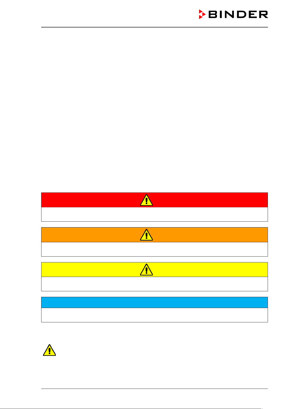
1.4.1 Signal word panel
Depending on the probability of serious consequences, potential dangers are identified with a signal word,
the corresponding safety color, and if appropriate, the safety alert symbol.
DANGER
Indicates an imminently hazardous situation that, if not avoided, will result in death or serious (irreversible) injury.
WARNING
Indicates a potentially hazardous situation which, if not avoided, could result in death or serious (irreversible) injury.
CAUTION
Indicates a potentially hazardous situation which, if not avoided, may result in moderate or minor (reversible) injury.
NOTICE
Indicates a potentially hazardous situation which, if not avoided, may result in damage to the product
and/or its functions or of a property in its proximity.
1.4.2 Safety alert symbol
Use of the safety alert symbol indicates a risk of injury.
Observe all measures that are marked with the safety alert symbol in order to avoid death or
injury.
KB / KB-UL (E4 + E6) 11/2020 page 7/149
Page 8
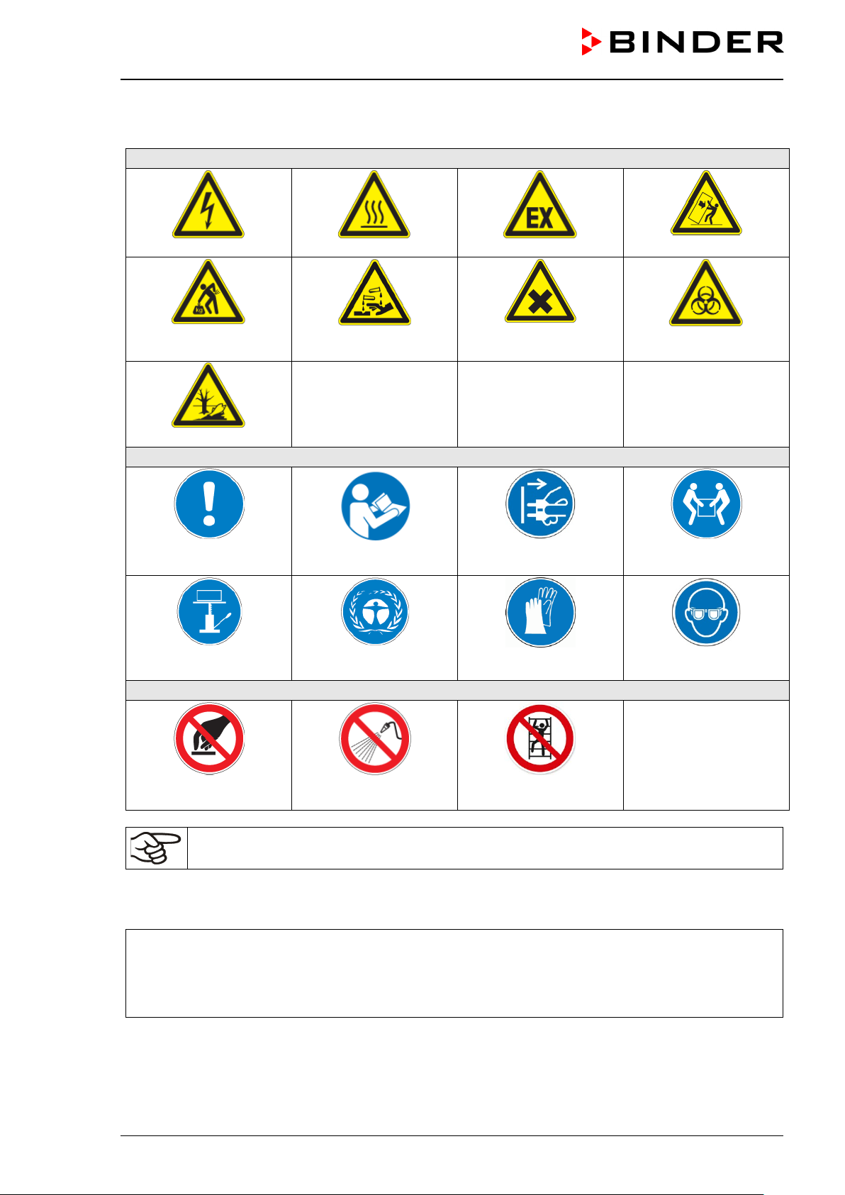
Warning signs
Electrical hazard
Hot surface
Explosive atmosphere
or chemical burns
Pollution Hazard
Mandatory action signs
instructions
plug
assistance
Prohibition signs
water
1.4.3 Pictograms
Lifting hazard
Mandatory regulation
Lift with mechanical
Risk of corrosion and /
Read operating
Environment protection
Harmful substances
Disconnect the power
Wear protective gloves
Stability hazard
Biohazard
Lift with several persons
Wear safety goggles
Do NOT touch
Information to be observed in order to ensure optimum function of the product.
Do NOT spray with
Do NOT climb
1.4.4 Word message panel structure
Type / cause of hazard.
Possible consequences.
∅ Instruction how to avoid the hazard: prohibition
Instruction how to avoid the hazard: mandatory action
Observe all other n otes and informat ion not necessarily em phasized in the sam e way, in order to a void
disruptions that could result in direct or indirect injury or property damage.
KB / KB-UL (E4 + E6) 11/2020 page 8/149
Page 9
Nominal temp.
100 °C
1,20 kW / 5,2 A
Max. operating pressure 15 bar
212 °F
200-230 V / 50 Hz
R 134A – 0,35 kg
IP protection
20
200-230 V / 60 Hz
Contains fluorinated greenhouse gases
Safety device
DIN 12880
1 N ~
covered by the Kyoto Protocol
Class
3.1
Art. No.
9020-0202
Built
2020
Cooling
BINDER GmbH
www.binder-world.com
KB 240
Serial No. 00000000000000
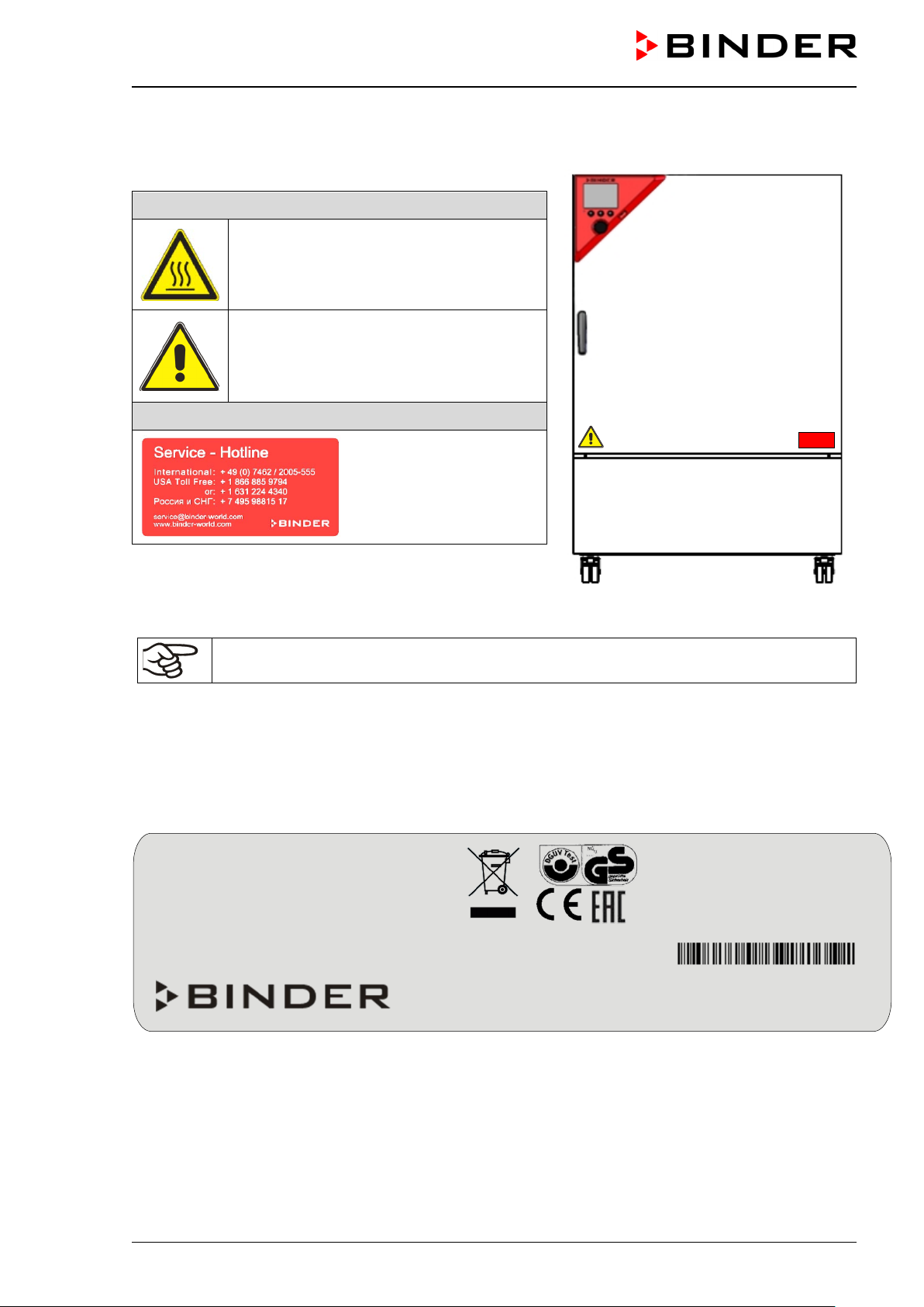
1.5 Localization / position of safety labels on the chamber
The following labels are located on the chamber:
Pictograms (Warning signs)
Hot surface
• Inner glass door above the glass door
handle
Read operating manual
• UL chambers: outer chamber door
• Chamber with opt ion al int erior socket:
below the interior socket
Service label
Figure 1: Position of labels on the chamber (example KB 240-UL)
Keep safety labels complete and legible.
Replace safety labels that are no longer legible. Contact BINDER Service for these replacements.
1.6 Type plate
The type plate sticks to the left side of the chamber, bottom right-hand.
Project No.
incubator
Im Mittleren Ösch 5
78532 Tuttlingen / Germany
E6
Figure 2: Type plate (example of KB 240 regular chamber)
Made in Germany
KB / KB-UL (E4 + E6) 11/2020 page 9/149
Page 10
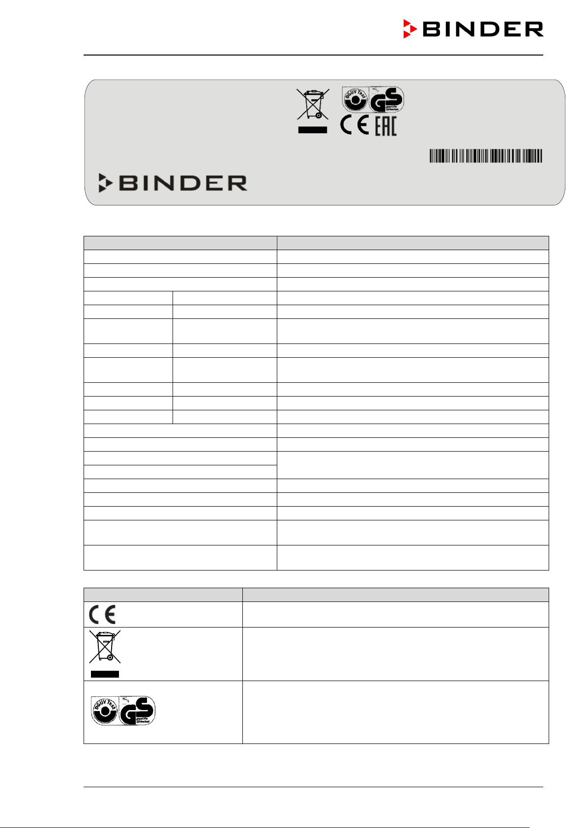
Indications of the type plate (example)
Information
BINDER
Manufacturer: BINDER GmbH
KB 240
Model designation
Cooling incubator
Device name
Serial No.
00000000000000
Serial no. of the chamber
Built
2020
Year of construction
Nominal temperature
100 °C
212 °F
IP protection
20
IP type of protection acc. to standard EN 60529
Temp. safety device
Temperature safety device acc. to standard DIN
12880:2007
Class
3.1
Class of temperature safety device
Art. No.
9020-0202
Art. no. of the chamber
Project No.
---
Optional: Special application acc. to project no.
1,20 kW
Nominal power
5,2 A
Nominal current
200-230 V / 50 Hz
200-230 V / 60 Hz
1 N ~
Current type
Max. operating pressure 15 bar
Max. operating pressure in the refrigerating system
R 134A - 0,35 kg
Refrigerant type and max. filling weight
Contains fluorinated greenhouse gases
covered by the Kyoto Protocol
Contains fluorinated greenhouse gases covered by the
Kyoto Protocol
With option internal socket:
Nominal power: 1,70 kW
Symbol on the type plate
Information
Nominal temp.
100 °C
1,20 kW / 5,2 A
Max. operating pressure 15 bar
212 °F
200-230 V / 50 Hz
R 134A – 0,35 kg
IP protection
20
200-230 V / 60 Hz
Contains fluorinated greenhouse gases
Safety device
DIN 12880
1 N ~
covered by the Kyoto Protocol
Class
3.1 With option internal socket:
Art. No.
9120-0202
Nominal power: 1,70 kW
Built
2020
Cooling incubator
BINDER GmbH
www.binder-world.com
KB 240
Serial No. 00000000000000
Project No.
Im Mittleren Ösch 5
78532 Tuttlingen / Germany
E6
Figure 3: Type plate (example of KB 240 optional chamber)
Nominal temperature
DIN 12880
Made in Germany
Nominal voltage range +/-10%
at the indicated power frequency
With option internal socket: increased total nominal power
CE conformity marking
Electrical and electronic equipment manufactured / placed on the
market in the EU after 13 August 2005 and to be disposed of in
separate collection according to Directive 2012/19/EU on waste
electrical and electronic equipment (WEEE).
GS mark of conformity of the “Deutsche Gesetzliche Unfallversicherung e.V. (DGUV), Prüf- und Zertifizierungsstelle Nahrungsmittel
und Verpackung im DGUV Test“ (German Social Accident Insurance (DGUV), Testing and Certification Body for Foodstuffs and
Packaging Industry in DGUV Test). (Not valid for UL chambers)
KB / KB-UL (E4 + E6) 11/2020 page 10/149
Page 11
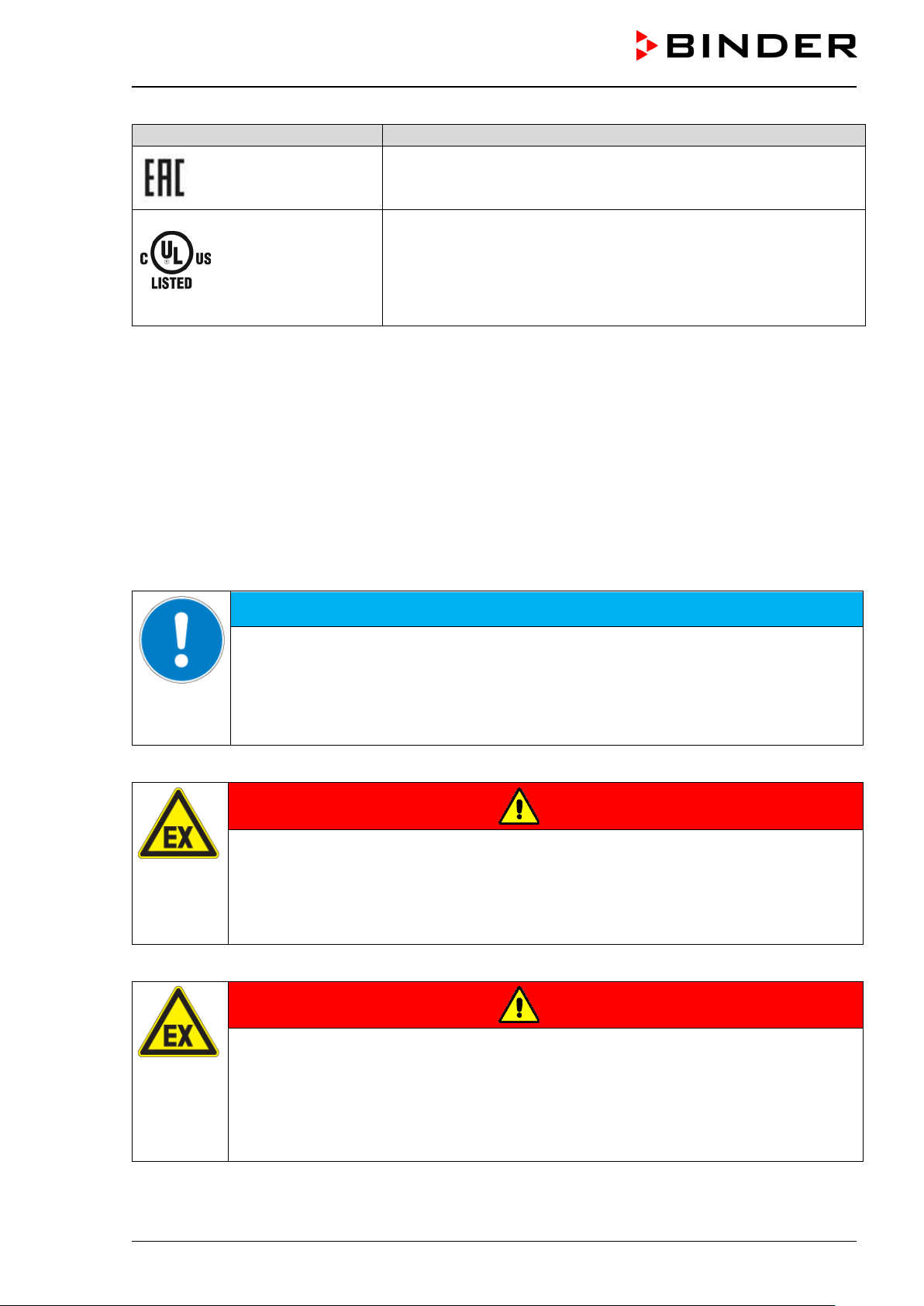
Symbol on the type plate
Information
NOTICE
LABORATORY EQUIPMENT
43KM
The chamber is certified according to Customs Union Technical
Regulation (CU TR) for the Eurasian Economic Union (Russia, Belarus, Armenia, Kazakhstan Kyrgyzstan).
The chamber is certified by Underwriters Laboratories Inc.
®
accord-
ing to the following standards:
rd
(KB-UL only)
• UL 61010-1, 3
• CAN/CSA-C22.2 No. 61010-1, 3
• IEC/EN 61010-1:2014, 3
Edition, 2012-05, Rev. 2015-07
rd
Edition, 2012-05, Rev. 2015-07
rd
Edition
1.7 General safety instructions on installing and operating the chambers
With regard to operating the chambers and to the installation location, please observe the local and national
regulations relevant for your country (for Germany: DGUV guidelines 213-850 on safe working in laboratories, issued by the employers’ liability insurance association).
BINDER GmbH is only respons ible for th e safet y features of th e chamber provided sk illed electric ians or
qualified personnel authorized by BINDER perform all maintenance and repair, and if components relating
to chamber safety are replaced in the event of failure with original spare parts.
To operate the cham ber, use onl y original BIND ER acc essories or acc essories from third-part y suppliers
authorized by BINDER. The user is responsible for any risk caused by using unauthorized accessories.
Danger of overheating due to lack of ventilation.
Damage to the chamber.
∅ Do NOT install the chamber in unventilated recesses.
Ensure sufficient ventilation for dispersal of the heat.
Observe the prescribed minimum distances when installing the chamber (chap. 3.4)
Do not install or operate the chambers in hazardous locations.
DANGER
Danger of explosion due to combustible du sts or explosive mixtures in the vicinity
of the chamber.
Serious injury or death from burns and / or explo sion pressure.
∅ Do NOT operate the chamber in potentially explosive areas.
KEEP combustible dust or air-solvent mixtures AWAY from the chamber.
The chambers do not dispose of any measures of explosion protection.
KB / KB-UL (E4 + E6) 11/2020 page 11/149
DANGER
Danger of explosion due to introduction of flammable or explosive substances in
the chamber.
Serious injury or death from burns and / or explo sion pressure.
∅ Do NOT introduce any substance into the chamber which is combustible or explosive at
working temperature.
∅ Do NOT introduce any combustible dust or air-solvent mixture in the inner chamber.
Page 12
Any solvent contai ned in th e charging m aterial m ust not be explosive or inflammabl e. I.e., irres pective of
the solvent concentrati on in the steam room, NO explos ive mixture with air m ust form. The temperature
inside the cham ber m ust lie belo w the f lash point or belo w the su blim ation point of the ch arging mater ial.
Familiarize yourself with the physical and chemical properties of the charging material, as well as the contained moisture constituent and its behavior with the addition of heat energy.
Familiarize yourself with any potential health risks caused by the charging material, the contained moisture
constituent or by reaction products which may arise during the temperature process. Take adequate
measures to exclude such risks prior to putting the cooling incubator into operation.
DANGER
Electrical hazard by water entering the chamber.
Deadly electric shock.
∅ The chamber must NOT become wet during operation, cleaning, or maintenance.
∅ Do NOT install the chamber in damp areas or in puddles.
Set up the chamber in a way that it is splash-proof.
The chambers were produced in accordance with VDE regulations and were routinely tested in accordance
to VDE 0411-1 (IEC 61010-1).
During and shortl y after operation, th e temperat ure of the inner surfac es almos t equals the set-point. The
glass doors, the glass door handles, and the inner chamber will become hot during operation.
CAUTION
Danger of burning by touching hot chamber parts during operation.
Burns.
∅ Do NOT touch the glass doors, the glass door handles, the inner surfaces or the charg-
ing material during operation.
WARNING
Danger of injury and damages by the chamber tipping over or breakaway of the protruding lower housing cover.
Injuries and damage to the chamber and the loading material
∅ Do NOT load the lower housing cover with heavy objects while the chamber door is
open and do NOT climb on it.
KB / KB-UL (E4 + E6) 11/2020 page 12/149
Page 13
1.8 Intended use
Following the instructions in this operating manual and conducting regular maintenance work
(chap. 21.2) are part of the intended use.
Any use of the chambers that does not comply with the requirements specified in this Operating
Manual shall be considered improper use.
Other applications than those described in this chapter are not approved.
Use
Cooling incubators K B / KB-UL are suitable for exac t c onditioni ng of harm less materia ls. Bec ause of their
precise temperatur e accur ac y these d evices ar e espec iall y useful for c ultivati on of m icroor ganism s with a
narrow temperature opt imum in a range of 4 °C / 39.2°F to 37 °C / 98.6°F. Main fields of application are
tests of long-term storage (e.g. at 4 °C / 39.2°F), refrigerated incubation between 20 °C / 68°F and 25 °C /
77°F and incubation at 37 °C / 98.6°F (also with additional introduction of heat) or with alternating temperatures (e.g. 37 °C / 98.6°F and 4 °C / 39.2°F).
Requirements for the chamber load
Any solvent must not be ex plosive and flamm able. A mixture of any component of the charging mater ial
with air must NO T be explosive. The opera ting temperature must lie below the flash point or below the
sublimation point of the chargin g material. A ny componen t of the charg ing mater ial must NOT be able to
release toxic gases.
The charging mater ial shall not conta in any corrosi ve ingredients that may damage th e machine com ponents made of stainless steel, aluminum, and copper. Such ingredients include in particular acids and halides. Any corrosive damage caused by such ingredients is excluded from liability by BINDER GmbH.
The chamber does not dispose of any measures of explosion protection.
DANGER
Explosion or implosion hazard and danger of poisoning through the introduction of
unsuitable loading material.
Poisoning. Serious injury or death from burns and / or explosion pressure.
∅ Do NOT introduce any substance combustible or explosive at working temperature into
the chamber, in particular no energy sources such as batteries or lithium-ion batteries.
∅ NO explosive dust or air-solvent mixture in the inner chamber.
∅ Do NOT introduce any substance which could lead to release of toxic gases.
Contamination of the chamber by toxic, infectious or radioactive substances must be prevented
WARNING
Danger of intoxication and infection through contamination of the chamber with
toxic, infectious or radioactive substances.
Damages to health.
Protect the interior of the chamber from contamination by toxic, infectious or radioactive
substances.
Take suitable protective measures when introducing and removing toxic, infectious or
radioactive material
KB / KB-UL (E4 + E6) 11/2020 page 13/149
Page 14
In case of foreseeable use of the chamber there is no risk for the user through the integration of the chamber
into systems or by special environmental or operating conditions in the sense of EN 61010-1:2010. For this,
the intended use of the chamber and all its connections must be observed.
Medical devices
The chambers are not classified as medical devices as defined by the Medical Device Directive 93/42/EEC.
Due to the special demands of the Medical Device Directive (MDD), these chambers are not
qualified for sterilization of medical devices as defined by the directive 93/42/EWG.
Personnel Requirements
Only trained personnel with knowledge of the Operating Manual can set up and install the chamber, start it
up, operate, clean, and tak e it out of op eration. Ser vic e and repair s cal l f or further technical req uirem ents
(e.g. electrical know-how), as well as knowledge of the service manual.
Installation site requirements
The chambers are designed for setting up inside a building (indoor use).
The requirements des cribed in the Operating Ma nual for installation site and ambient conditions (Chap.
3.4) must be met.
WARNING: If customer should use a BINDER chamber running in non-supervised continu-
ous operation, we strongly recommend in case of inclusion of irrecoverable specimen or
samples to split such specimen or samples and store them in at least two chambers, if this is
feasible.
1.9 Foreseeable Misuse
Other applications than those described in chap. 1.8 are not approved.
This expressly incl udes the following misuses (the list is not exhaustive), which pos e risks despite the
inherently safe construction and existing technical safety equipment:
• Non-observance of Operating Manual
• Non-observanc e of inf ormation and warnings on the chamber (e.g. co ntrol unit messages, saf et y ide n-
tifiers, warning signals)
• Installation , startup, operation, m aintenance and repair by untrained, insufficientl y qualified, or unau-
thorized personnel
• Missed or delayed maintenance and testing
• Non-observance of traces of wear and tear
• Insertion of materials excluded or not permitted by this Operating Manual.
• Non-compliance with the admissible parameters for processing the respective material.
• Installation, testing, service or repair in the presence of solvents
• Installation of replacement parts and use of accessories and operating resources not specified and au-
thorized by the manufacturer
• Installation , startup, operat ion, maintenance or repair of the c hamber in absence of operating instr uc-
tions
• Bypassing or c hang in g pr ot ec tive systems, operation of the c hamber without the designated pr otec t ive
systems
• Non-observance of messages regarding cleaning and disinfection of the chamber.
• Spilling water or clean ing agent on the cham ber, water penetrating into the c hamber dur ing operat ion,
cleaning or maintenance.
KB / KB-UL (E4 + E6) 11/2020 page 14/149
Page 15

• Cleaning activity while the chamber is turned on.
• Operation of the chamber with a damaged housing or damaged power cord
• Continued operation of the chamber during an obvious malfunction
• Insertion of objects, particularly metallic objects, in louvers or other openings or slots on the chamber
• Human error (e.g. insufficient experience, qualification, stress, exhaustion, laziness)
To prevent these and other risks fr om incorrect operati on, the operator s hall issue operating instruc tions.
Standard operating procedures (SOPs) are recommended.
1.10 Residual Risks
The unavoidable design features of a chamber, as well as its proper field of application, can also pose risks,
even during corr ect operation. These res id ua l ris ks include hazards whic h , d es pite the inherentl y safe design, existing technica l protec tive equipm ent , safet y prec autions an d supp lem entary protect ive m easures ,
cannot be ruled out.
Messages on the chamber and in the Operating Manual warn of residual risks. The consequences of these
residual risks and the measures required to prevent them are listed in the Operating Manual. Moreover, the
operator must take measures to minimize hazards from unavoidable residual risks. This includes, in particular, issuing operating instructions.
The following list s ummarizes the hazar ds against which this Operating Manua l and the Service Man ual
warn, and specifies protective measures at the appropriate spots:
Unpacking, Transport, Installati on
• Sliding or tilting the chamber
• Setup of the chamber in unauthorized areas
• Installation of a damaged chamber
• Installation of a chamber with damaged power cord
• Inappropriate site of installation
• Missing protective conductor connection
Normal operation
• Assem bly errors
• Contact with hot surfaces on the housing
• Contact with hot surfaces in the interior and inside of doors
• Emission of non-ionizing radiation from electrical operating resources
• Contact with live parts in normal state
Cleaning and Decontamination
• Penetration of water into the chamber
• Inappropriate cleaning and decontamination agents
• Enclosure of persons in the interior
Malfunction and Damage
• Continued oper atio n of th e c ham ber during an ob vious m alfunc tion or out age of the he ating or cool ing
system
• Contact with live parts during error status
• Operation of a unit with damaged power cord
KB / KB-UL (E4 + E6) 11/2020 page 15/149
Page 16
Maintenance
• Maintenance work on live parts.
• Execution of maintenance work by untrained/insufficiently qualified personnel
• Electrical safety analysis during annual maintenance not performed
Trouble-shooting and Repairs
• Non-observance of warning messages in the Service Manual
• Trouble-shooting of live parts without specified safety measures
• Absence of a plausibility check to rule out erroneous inscription of electrical components
• Performance of repair work by untrained/insufficiently qualified personnel
• Inappropriate repairs which do not meet the quality standard specified b y BINDER
• Use of replacement parts other than BINDER original replacement parts
• Electrical safety analysis not performed after repairs
1.11 O perating instructions
Depending on the a pplicati on and loc ation of the c ham ber, the operator of the cham ber must pr ovide the
relevant information for safe operation of the chamber in a set of operating instructions.
Keep these operating instructions with the chamber at all times in a place where they are
clearly visible. They must be comprehensible and written in the language of the employees.
1.12 Measures to prevent accidents
The operator of the chamber must observe the following rule: “Betreiben von Arbeitsmitteln. Betreiben von
Kälteanlagen, W ärmepumpen und Kühlei nrichtungen“ (Operation of work equipment. Operati on of refrigeration systems, heat pumps and refrigeration equipment) (GUV-R 500 chap. 2.35) (for Germany).
The manufacturer took the follo wing m eas ures to prevent ign iti on and ex plos io ns :
• Indications on the type plate
See operating manual chap. 1.6.
• Operating manual
An operating manual is available for each chamber.
• Overtemperature monitoring
The chamber is equipped with a temperature display, which can be read from outside.
The chamber is equipped with an add ition al safet y control ler (tem per ature saf ety dev ice class 3.1 acc .
to DIN 12880:2007). Visual and audible (buzzer) signals indicate temperature exceeding.
• Safety, measurement, and control equipment
The safety, measuring, and control equipment is easily accessible.
• Electrostatic ch arg e
The interior parts are grounded.
KB / KB-UL (E4 + E6) 11/2020 page 16/149
Page 17

• Non-ionizing radiation
Non-ionizing radiation is not intentionally produced, but released only for technical reasons by electrical
equipment (e.g. elec tr ic motors, power cables, sol eno i ds) . The machine has no permanent magnets. If
persons with active im plants (e.g. pacemakers, def ibrillators) keep a safe distance (distance of field
source to implant) of 30 cm, an influence of these implants can be excluded with high probability.
• Protection against touchable surfaces
Tested according to EN ISO 13732-1:2008.
• Floors
See operating manual chap. 3.4 for correct installation
• Cleaning
See operating manual chap. 20.
• Examinations
The chamber has been ins pec ted by the “Deutsche Gesetzlich e Unf al lv ers icher u ng e. V. ( DG UV) ( Ger man Social Accident Insurance (DGUV)” (German Social Accident Insurance (DGUV), Testing and Certification Body for Foodstuffs and Packaging Industry in DGUV Test) and bears the GS mark. (Not vali d
for UL chambers)
®
UL units only: The cham ber is certified by Underwriters Laboratories Inc.
rd
standards: UL 6 1010-1, 3
2012-05, Rev. 2015-07; IEC/EN 61010-1:2014, 3
Edition, 2012-05, Rev. 2015-07; C AN/CS A-C22.2 N o. 61010-1, 3rd Edition,
rd
Edition
according to the fol lowing
KB / KB-UL (E4 + E6) 11/2020 page 17/149
Page 18

2. Chamber description
A high level of prec is ion, re lia bi lit y, an d s af ety for all growth parameters ensures optimum incubation conditions. Moreover, the KB / KB-UL cooling incubator is designed for maximum usability – even in continuous
operation year after year . It f ulf ills al l tech nic a l a nd a pp licat ion-specific requirem ents aris ing in exper imentation such as in the areas of biotechnology, medicine, the nutrition industry, pharmaceutical and cosmetics
industries, botany, and zoology.
Two important temperature technologies have been combined to achieve perfect temperature control. The
specially developed DCT™ refrigerating system, a direct refrigerating process, in conjunction with the
APT.line™ preheat ing chamber technology, satisf ies the unique prer equisites for attaining highl y-precise
temperature control and particularly short recovery times after opening the door.
The refrigerating system is distinguished by direct, pre c ise, and r ap id temperature conduction. Lar g e-area
labyrinth evaporator plates directly conduct the cold to the atmosphere of the working space.
The APT.line™ preheating chamber system ensures high level of spatial and time-based temperature precision, thanks to the dir ect and distributed air circ ulation into the interior . This is especially impor tant for
maintaining temper atures – especially with full cham bers – and for rapid restor ation of optimum growth
conditions after ope ning the door. The inner glass door ensures that the tem perature remains constant
when observing the incubation process. The fan supports exact attainment and maintenance of the desired
temperature accurac y. The fan speed is digi tally adjustable. The heatin g and refrigerating system s are
microprocessor regulated to a tenth of a degree. In addition, the chamber provides almost unlimited possibilities for adaptation to individual customer requirements based upon extensive programming options and
on the week program timer and real time clock of the controller.
The KB / KB-UL 240 / 400 / 720 (E6) chambers are equipped with a door heating.
All chamber functions are eas y and comfor table to use thank s to their cle ar arrangem ent. Major f eatures
are easy cleaning of all chamber parts and avoidance of undesired contamination.
Material: The inner cham ber, the pre-hea ting chamber and the interior side of the doors are all made of
stainless steel V2A (German material no. 1.4301, US equivalent AISI 304). The housing is RAL 7035 powder-coated. All corners and edges are also completely coated.
The chamber com es equipped with an Ether net interf ace for com puter com munication, e .g. via th e APTCOM™ 4 Multi Management Software (option, chap. 19.1). For further options, see chap. 23.5.
The KB / KB-UL 240 / 400 / 720 (E6) chambers are equipped with
be locked via the attached brakes.
Temperature range at ambient temperature of +22 °C +/- 3°C / 71.6 °F +/- 5.4 °F: -10 °C / 14 °F up to
+100 °C / 212 °F
four castors. Both front castors can easily
KB / KB-UL (E4 + E6) 11/2020 page 18/149
Page 19
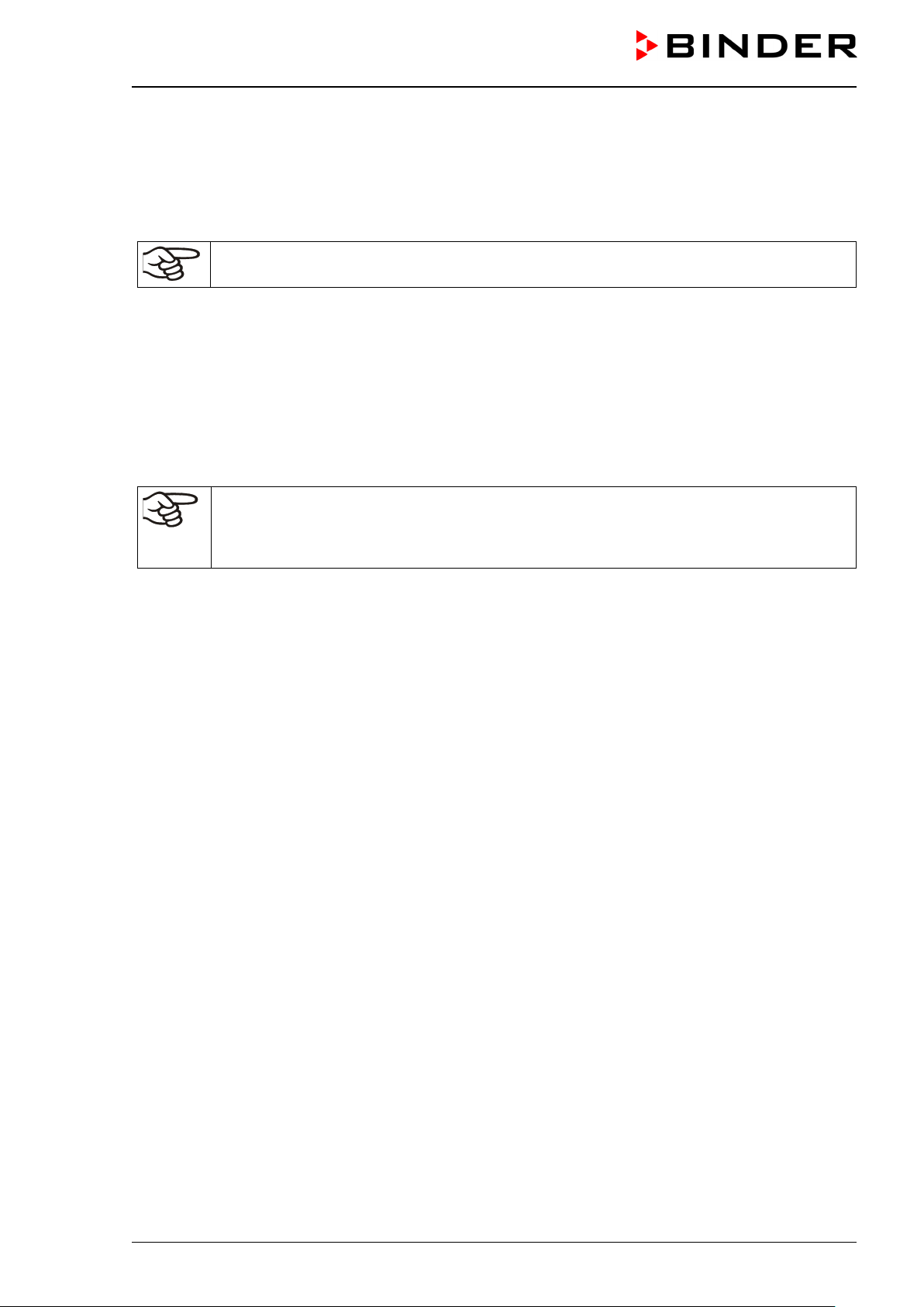
2.1 Chamber overview
Instrument panel with microprocessor
controller T4.12 and USB interface
Door handle
Chamber door
Refrigerating module
Main power switch (1)
Figure 4: Cooling incubator KB / KB-UL 53 / 115 (E4)
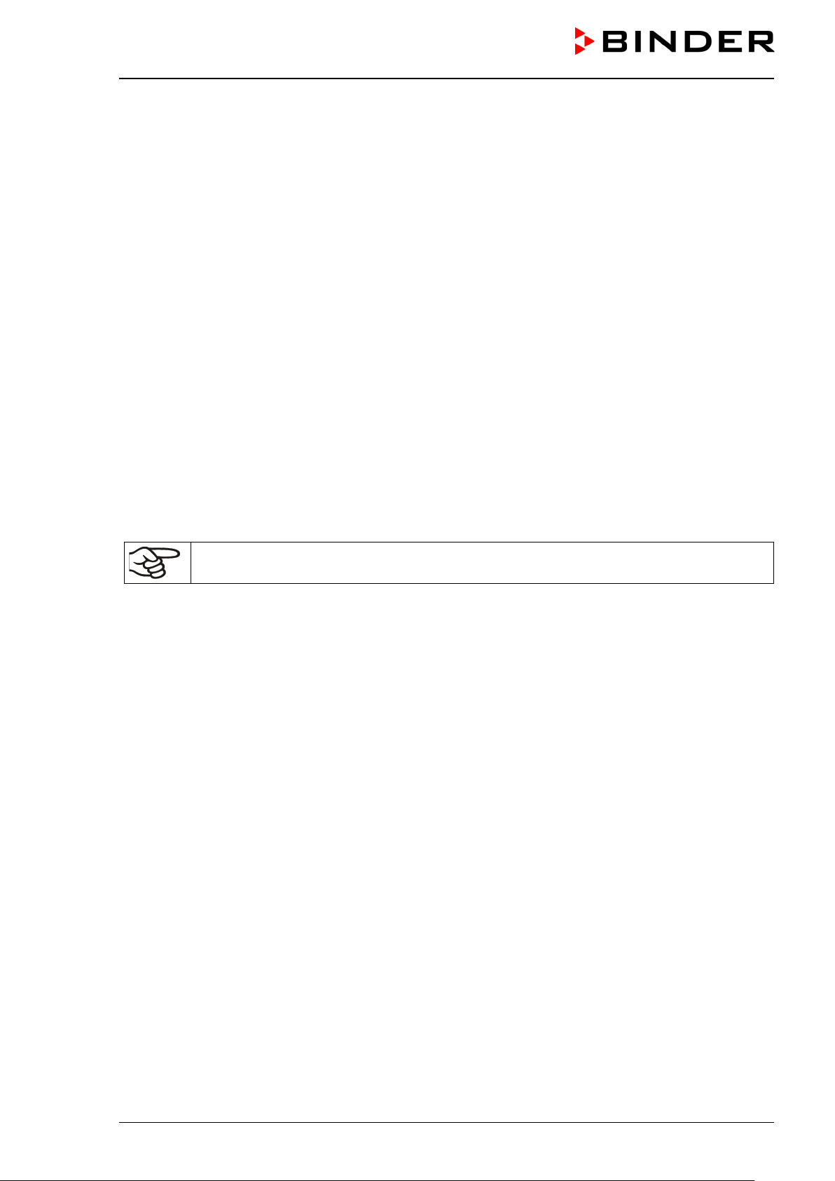
Instrument panel with microproces-
sor controller T4.12 and USB inter-
Lateral control panel with main power
face
Door handle
Chamber door
Refrigerating module
switch and connections
Figure 5: Cooling incubator KB / KB-UL 240 / 400 / 720 (E6)
KB / KB-UL (E4 + E6) 11/2020 page 19/149
Page 20
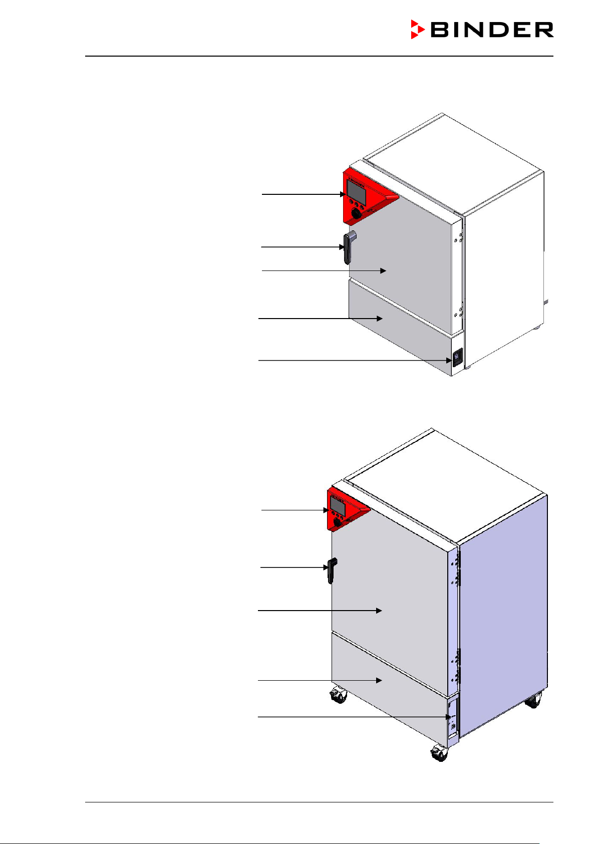
2.2 Instrument panel
5,7" controller display
Context-sensitive buttons
USB interface
Operating button
Pilot lamp: ready for operation
Figure 6: Instrument panel with microprocessor controller T4.12 and USB interface
KB / KB-UL (E4 + E6) 11/2020 page 20/149
Page 21
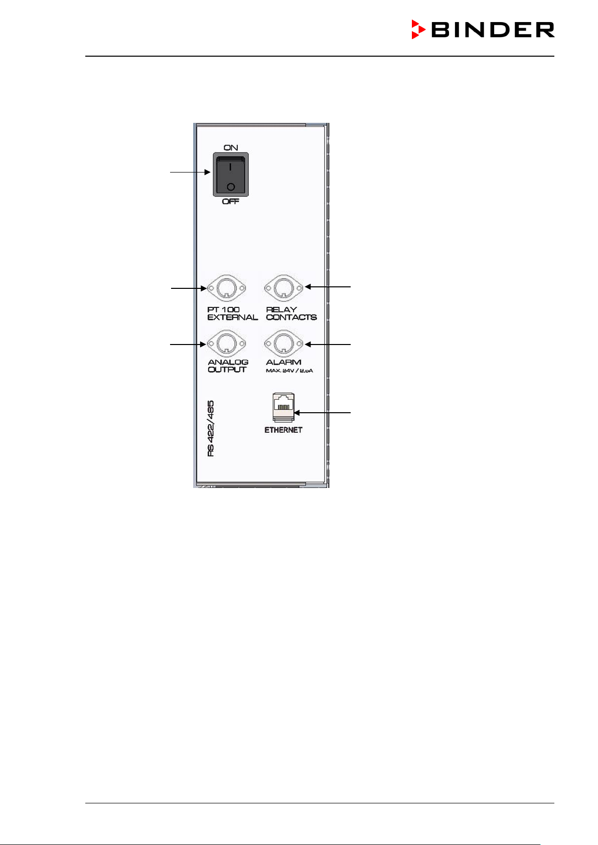
2.3 Lateral control panel with main power switch and optional equipment –
KB / KB-UL 240 / 400 / 720 (E6)
(1)
(2)
(3)
(5)
(6)
(7)
Figure 7: Lateral control panel at the right side of the refrigerating machine, with options
(1) Main power switch
(2) DIN-socket for additiona l Pt 100 temperature sensor (m ay be available via BINDER INDIVIDUAL
Customized Solutions)
(3) DIN socket for analog output 4-20 mA (option)
(4) (not used)
(5) DIN-socket for zero-voltage relay control o utputs ( ma y be availab le via BIN DER I NDIVIDUA L Cus-
tomized Solutions)
(6) DIN-socket for zero-voltage relay alarm output (option)
(7) Ethernet interface for computer communication
KB / KB-UL (E4 + E6) 11/2020 page 21/149
Page 22
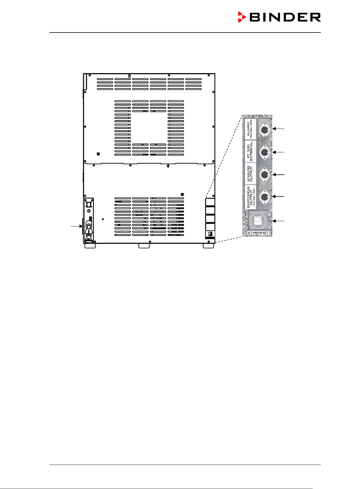
(8)
2.4 Chamber rear – KB / KB-UL 53 / 115 (E4)
(6)
(2)
(3)
(5)
(7)
Figure 8: Chamber rear with position of options (example)
(2) DIN-socket for additiona l Pt 100 temperature sensor (m ay be available via BINDER INDIVIDUAL
Customized Solutions)
(3) DIN socket for analog output 4-20 mA (option)
(4) (not used)
(5) DIN-socket for zero-voltage relay contro l outputs (may be av ailable v ia BINDER INDIVID UAL C us-
tomized Solutions)
(6) DIN-socket for zero-voltage relay alarm output (option)
(7) Ethernet interface for computer communication
(8) Power cable
KB / KB-UL (E4 + E6) 11/2020 page 22/149
Page 23
53 / 115 from the p al let with the a i d of four people in the are a of al l
240 from the pallet with the aid of six people in t he area of all 4
3. Completeness of delivery, transportation, storage, and installa-
tion
3.1 Unpacking, and checking equipment and completeness of delivery
After unpacking, p lease check the chamber and its o ptional accessories, if any, based on the delivery
receipt for completenes s and for transportation damage. Inf orm the carrier immediately if transportation
damage has occurred.
The final tests of the manufacturer may have caused traces of the shelves on the inner surfaces. This has
no impact on the function and performance of the chamber.
Please remove any transportati on protection devices and adh esives in/o n the cham ber and on the do ors
and remove the operating manuals and accessory equipment.
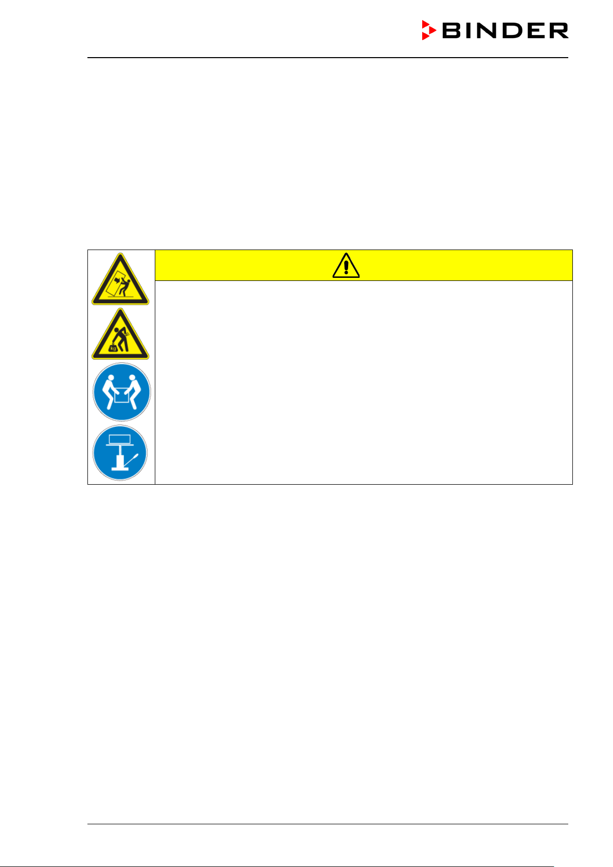
CAUTION
Risk of injury and damages by lifting heavy loads and by sliding or tilting of the
chamber due to improper lifting.
Injuries, damage to the chamber.
∅ Do NOT lift or transport the chamber using the door, the handle, or the lower housing.
∅ Do NOT lift chambers sizes 400 / 720 by hand.
Lift chamber s si zes
4 chamber feet.
Lift c hambers size
chamber feet or use a fork lifter. Set the fork lifter only from the front or rear in the middle
of the chamber.
Lift chambers sizes 400 / 720 using technical devices (fork lifter) from the pallet. Set the
fork lifter only from the front or rear in the middle of the chamber.
∅ Do NOT set the fork lifter from the chamber side.
If you need to return the chamber, please use the original packing and observe the guidelines for safe lifting
and transportation (chap. 3.2).
For disposal of the transport packing, see chap. 22.1.
Note on second-hand chambers (Ex-Demo-Units):
Second-hand cham bers are chambers that were used f or a short time for tests or exhibitions. T hey are
thoroughly tested before resale. BINDER ensures that the chamber is technically sound and will work flawlessly.
Second-hand chambers are marked with a sticker on the chamber door. Please remove the sticker before
commissioning the chamber.
KB / KB-UL (E4 + E6) 11/2020 page 23/149
Page 24
3.2 Guidelines for safe lifting and transportation
The front castors of the chambers sizes 240 / 400 / 720 can be blocked by brakes. Please move the chambers with castors only when empty and on an even surface, otherwise the castors may be damaged. After
operation, please observe the guidelines for temporarily decommissioning the chamber (chap. 22.2).
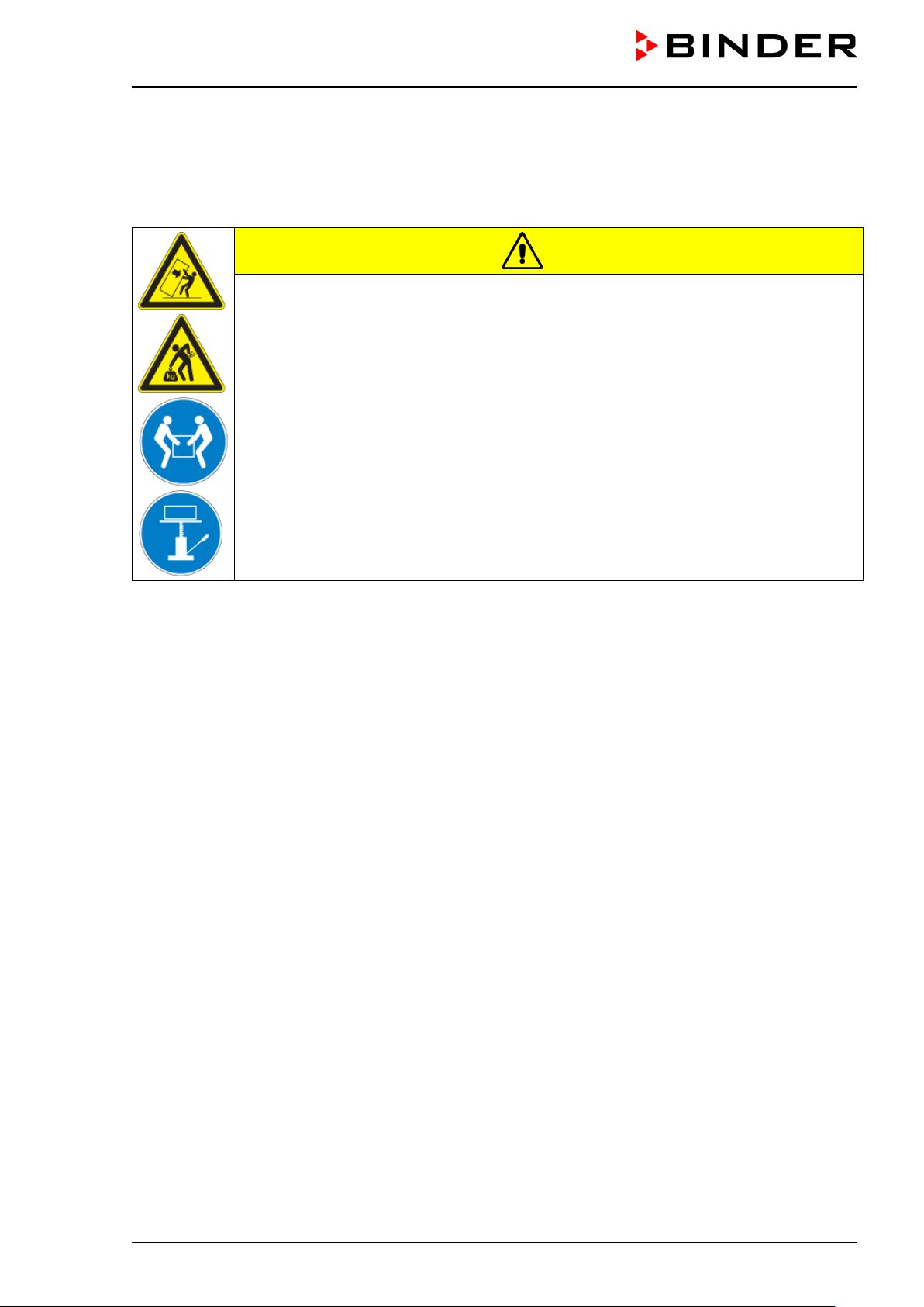
CAUTION
Risk of injury and damages by lifting heavy loads and by sliding or tilting of the
chamber due to improper transportation.
Injuries, damage to the chamber.
Transport the chamber in its original packaging only.
For moving or shipping, secure the chamber with transport straps.
∅ Do NOT lift or transport the chamber using the door, the handle, or the lower housing.
∅ Do NOT lift chambers sizes 400 / 720 by hand.
Lift chambers sizes 53 / 115 with the aid of four people in the area of all 4 chamber feet.
Lift chambers size 240 with the aid of 6 people or with a fork lifter. Set the fork lifter only
from the front or rear in the middle of the chamber.
Lift cham bers s izes 400 / 7 20 us ing t ech nic a l de vices (f ork lifter). Set the fork lifter onl y
from the front or rear in the middle of the chamber.
∅ Do NOT set the fork lifter from the chamber side.
• Permissible ambient temperature range during transport: -10 °C / 14°F to +60 °C / 140°F.
You can order transport packing for moving or shipping purposes from BINDER service.
3.3 Storage
Intermediate storage of the chamber is possible in a closed and dry room. Observe the guidelines for temporary decommissioning (chap. 22.2).
• Permissible ambient temperature range during storage: -10 °C / 14°F to +60 °C / 140°F.
• Permissible ambient humidity: max. 70 % r.H., non-condensing
When after storage in a cold location you transfer the chamber to its warmer installation site, condensation
may form. Befor e s tart -up, wait at le as t o ne ho ur un ti l t he c hamber has attained a mbient temperature and
is completely dry.
KB / KB-UL (E4 + E6) 11/2020 page 24/149
Page 25
NOTICE
3.4 Location of installation and ambient conditions
Set up the chamber on a flat, even surface, free from vibration, in a well-ventilated, dry location and align it
using a spirit lev el. T he sit e of install ation m ust be cap able of sup porti ng the cha m ber’s weight (see technical data, chap. 23.4). The chambers are designed for setting up inside a building (indoor use).
Danger of overheating due to lack of ventilation.
Damage to the chamber.
∅ Do NOT install the chamber in unventilated recesses.
Ensure sufficient ventilation for dispersal of the heat.
Observe the prescribed minimum distances when installing the chamber.
Do not install or operate the chamber in potentially explosive areas.
DANGER
Danger of explosion due to combustible du sts or explosive mixtures in the vicinity
of the chamber.
Serious injury or death from burns and / or explo sion pressure.
∅ Do NOT operate the chamber in potentially explosive areas.
KEEP explosive dust or air-solvent mixtures AWAY from the vicinity of the chamber.
Ambient conditions
• Permiss ible ambient temper ature range during o peration: +18 °C / 64.4 °F to +32 °C / 89.6 °F. At ele-
vated ambient temperature values, fluctuations in temperature can occur.
The ambient temperature should not be substantially higher than the indicated ambient
temperature of +22 °C +/ - 3 °C / 71.6 °F +/- 5.4 °F to which the specified technical data relates. Deviations from the indicated data are possible for other ambient conditions.
With each degree of ambient temperature > +25 °C / 77°F, the refrigeration power decreases by 1.5 K.
• Permissible ambient humidity: 70 % r.H. max., non-condensing.
When operating the cham ber at temperature set -points below ambient t emperature, high am bient humidity may lead to condensation on the chamber.
• Installation height: max. 2000 m / 6562 ft. above sea level.
Minimum distances
• When placing several chambers of the same size side by side, maintain a minimum distance of 250 mm
/ 9.84 in between each chamber.
• Wall distances: rear 100 mm / 3.9 in, sides 160 mm / 6.29 in.
• Spacing above the chamber of at least 100 mm / 3.9 in must also be accounted for.
KB / KB-UL (E4 + E6) 11/2020 page 25/149
Page 26
Stacking
Two KB / KB-UL 53 / 115 (E4) chambers of the sam e size can be piled on top of each other. For th is
purpose place rubber pads under every foot of the upper chamber to prevent the device from slipping.
NOTICE
Danger of damage caused by sliding or tilting of the upp er chamber.
Damage to the chambers.
When stacking, place rubber pads under every foot of the upper chamber.
Stack only chambers of the same size.
KB / KB-UL 240 / 400 / 720 (E6) chambers must NOT be stacked.
NOTICE
Danger by stacking.
Damage to the chambers.
∅ Do NOT place the cooling incubators on top of each other.
Other requirements
To completely separat e the cham ber from the power supp ly, you mus t disconnect t he power plug. Install
the chamber in a way that the power plug is easily accessible and can be easily pulled in case of danger.
For the user there is no risk of temporary overvoltages in the sense of EN 61010-1:2010.
With an increased amount of dust in the ambient air, clean the condenser fan (by suction or blowing) several
times a year.
Avoid any conductive dust in the ambiance according to the chamber layout complying with pollution degree
2 (IEC 61010-1).
KB / KB-UL (E4 + E6) 11/2020 page 26/149
Page 27
4. Installation of the chamber
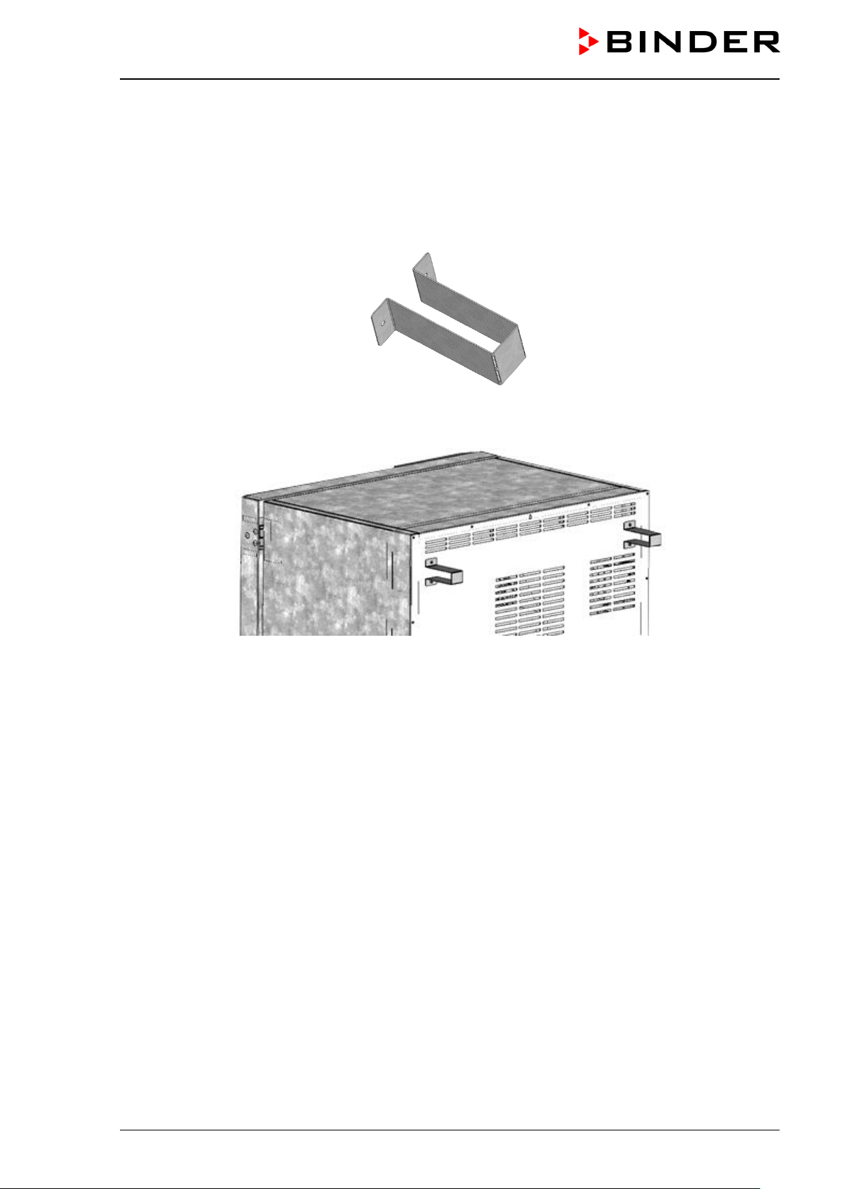
4.1 Spacers for wall distance – KB / KB-UL 240 / 400 / 720 (E6)
Please fix both spacers with the supplied screws at the chamber rear. This serves to ensure the prescribed
minimum distance to the wall of 100 mm / 3.94 in.
Figure 9: Spacer for rear wall distance
Figure 10: Rear KB / KB-UL 240 / 400 / 720 (E6) with mounted spacers
KB / KB-UL (E4 + E6) 11/2020 page 27/149
Page 28
(a)
(a)
(b)
(c) (c)
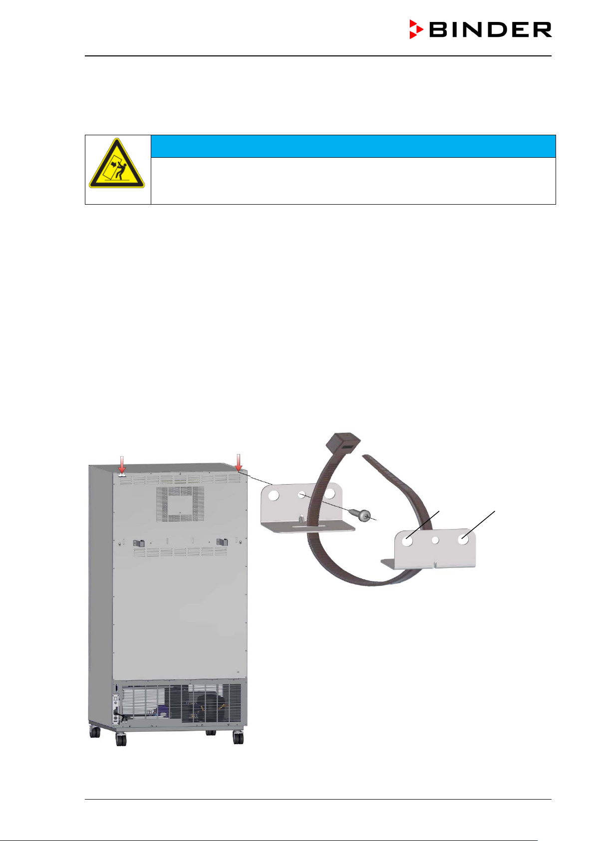
4.2 Mounting the flexible tilt protection kit
Use the supplied f lexible ti lt protect ion k it in additio n to the spacers f or wall distanc e (chap. 4.1). T his w ill
prevent the chamber from tilting when the door is open.
NOTICE
Danger of damages caused by tilting of the chamber when the door is open.
Damage to the chamber.
Fix the chamber to a wall with supplied flexible tilt protection kit
Scope of delivery:
• 4 Torx screws (spare parts)
• 4 tilt protection holders
• 4 securing straps (2 spare parts)
Mounting on device side:
• Remove two screws on the upper part of the rear wall (a)
• Fix two of the supplied tilt protection holders, each centrally with one of these screws (b).
Mounting on wall side
• Fix two of th e s up pl ied tilt protection holders i n t he ap p r opriat e d is tanc e , e ac h wit h t wo sc r ews Ø 6mm
suitable for the wall (c)
Connection with the securing straps
• On each sid e, thread one of the supplied securing s traps through th e provided slots of a device side
and a wall side tilt protection holder
Figure 11: Rear chamber (example KB 400) and mounting the flexible tilt protection kit
KB / KB-UL (E4 + E6) 11/2020 page 28/149
Page 29
4.3 Electri cal co nn ect io n
The chambers are supplied ready for connection. They come with a fixed power connection cable that has
a length of at least 1800 m m / 5.9 ft and are protected with a chamber-protection against over c ur rent, t he
chambers KB 53-UL / KB 115-UL in addition with an internal fus e.
Model Power plug
KB 53 (E4)
KB 115 (E4)
KB 240 (E6)
KB 400 (E6)
KB 720 (E6)
KB 53-UL (E4)
KB 115-UL (E4)
KB 240-UL (E6)
KB 400-UL (E6)
KB 720-UL (E6) NEMA 6-20P
• The domes tic socket must also provide a protec tive conductor. Make s ure that the connection of the
protective conductor of the domestic installations to the chamber’s protective conductor meets the latest
technology. The protective conductors of the socket and plug must be compatible!
Shock-proof plug 230 V at 50 Hz 1N~ 10 A
Shock-proof plug
NEMA 5-15 115 V at 60 Hz 1N~ 12,5 A
NEMA 5-20P
Nominal voltage +/- 10% at the
indicated power frequency
200-230 V at 50 Hz
200-230 V at 60 Hz
100-120 V at 50 Hz
100-120 V at 60 Hz
200-240 V at 50 Hz
200-240 V at 60 Hz
Current
type
1N~ 16 A
1N~ 16 A
2 ~ 16 A
Chamber
fuse
DANGER
Electrical hazard due to missing protecti ve conductor connection.
Deadly electric shock.
Make sure that the chamber’s power plug and the power socket match and se-
curely connect the electrical protective conductors of the chamber and the house
installation.
• Only use original connection cables from BINDER according to the above specification.
• Prior to con nection and s tar t-up, chec k the po wer su ppl y voltag e. Com pare th e v alues to t he sp ecif ied
data located on the chamber’s type plate (left chamber side, bottom right-hand, see chap. 1.6).
NOTICE
Danger of incorrect power supply voltage due to improper connection.
Damage to the chamber.
Check the power supply voltage before connection and start-up.
Compare the power supply voltage with the data indicated on the type plate.
• When connect ing, please o bserve the regul ations spec ified by the local e lectricity s upply com pany as
well as the local or national electrical regulations (VDE directives for Germany).
• Observe a sufficient current protection according to the number of devices that you want to operate. We
recommend the use of a residual current circuit breaker.
• Pollution degree (acc. to IEC 61010-1): 2
• Over-voltage category (acc. to IEC 61010-1): II
See also electrical data (chap. 23.4).
KB / KB-UL (E4 + E6) 11/2020 page 29/149
Page 30
To completely separate the chamber from the power supply, you must disconnect the power
plug. Install the chamber in a way that the power plug is easily accessible and can be easily
pulled in case of danger.
5. Start up
After connecting th e electri cal suppl y (chap. 4.1), turn on the chamber by the m ain power switch ( 1). The
pilot lamp shows the chamber is ready for operation.
Observe a delay time of about 30s between turning Off and On again. Otherwise an initialization problem may occur.
Note that the cham ber is in stand-by mode when the m ain power s witch has bee n turned on an d yet the
controller display is dark. Turn on the chamber by pressing any controller button.
Warming chambers may release odors in the first few days after commissioning. This is not a quality defect.
To reduce odors quick ly we recomm end heating up the chamber to its nominal tem perature for one day
and in a well-ventilated location.
WARNING: If customer should use a BINDER chamber running in non-supervised continuous operation, we strongly recommend in case of inclusion of irrecoverable specimen or
samples to split such specimen or samples and store them in at least two chambers, if this is
feasible.
6. Functional overview of the T4.12 chamber controller
The T4.12 cham ber c ontr oller cont rols t he t emperature (range: -10 °C / 14 °F up to +100 °C / 212 °F) an d
the fan speed (range: 40 % up to 100 %) inside the chamber. You can enter the desired set point values in
fixed value operat ing mode or in program mode in the display contro ll er. The controller also of fers a week
program function and vari o us not if icati ons and alarm mess ages with visu al and audible in dicat ion, a trac e
file and remote alarm s via e-mail. You can enter values or programs directly at the controller k eypad or
using the APT-COM™ 4 Multi Management Software (option, chap. 19.1) specially developed by BINDER.
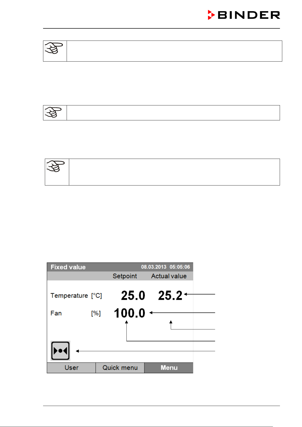
Temperature values
Fan speed value
Actual values
Set-point values
Icons:
Controller operating in
“fixed value” operating
mode
Figure 12: T4.12 microprocessor controller, initial view in “fixed value” controller mode (sample values)
KB / KB-UL (E4 + E6) 11/2020 page 30/149
Page 31
Fixed value
08.03.2015 05:05:06
Setpoint
Actual value
25.0
25.2
100.0
Menu
Fixed value
..\ Menu
Controller mode
Event list
Alarms
Setpoints
Safety controller
Programs
Import/Export
Settings
6.1 Menu structure
Temperature [°C]
Fan [%]
User Quick menu
From the Initial view you ha ve acc es s to dif f erent menus using the menu buttons “User”, “Quick menu”, or
“Menu”. From there you can access the desired control functions. To do this, select the function by turning
the operating button and press the operating button to confirm the selection.
In any menu, you can re turn to the previous disp lay pressing t he "Close" but ton or to th e initial view with
the "Home" button.
Depending on the logged-in user or administr ator, the availa ble m enu functions m ay vary. Thes e instruc tions present the functions which are available to the logged-in administrator.
Initial view (sample values).
Press the desired menu button.
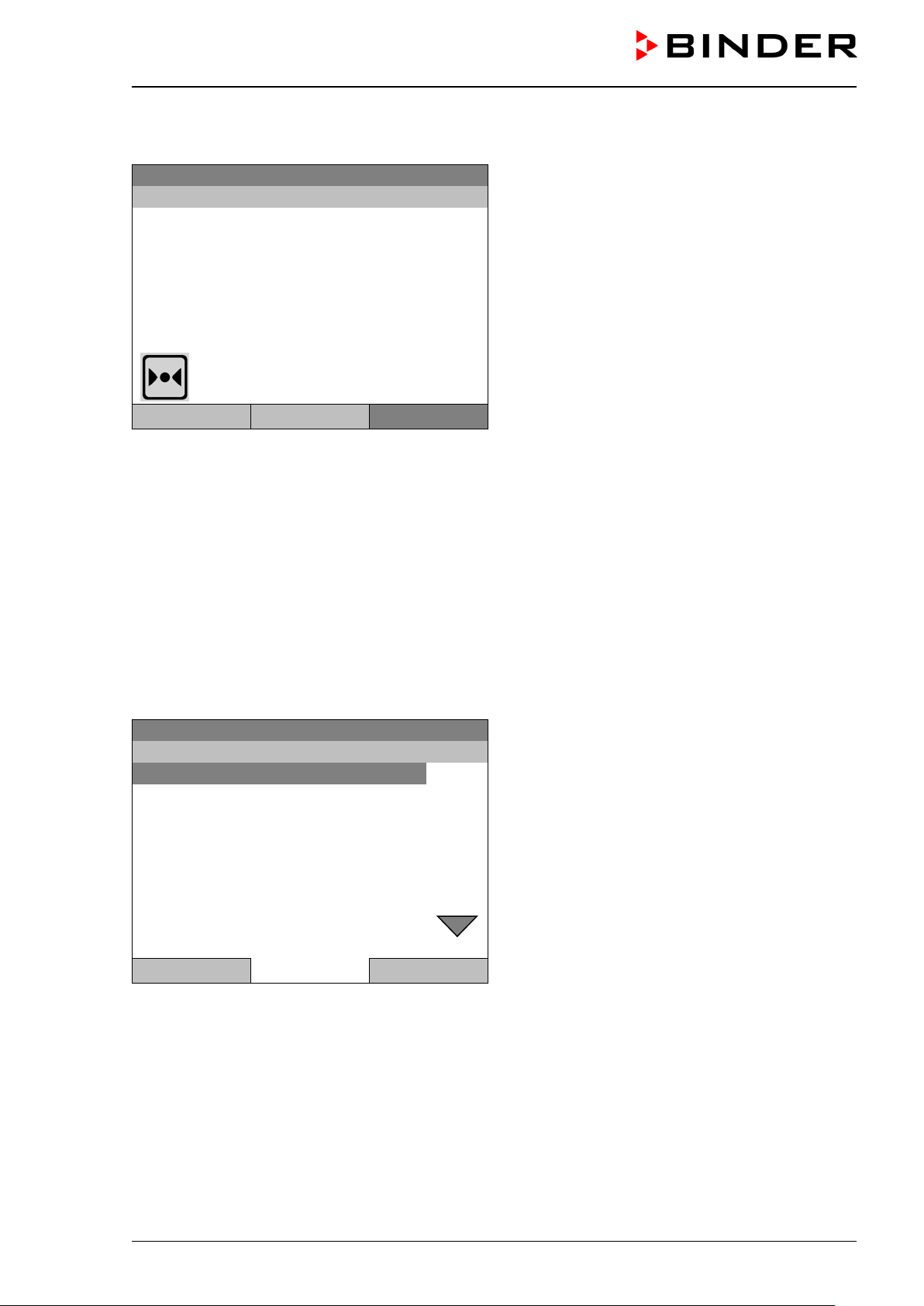
6.1.1 General menu
The general menu provides access to all setting functions of the controller, a graphical display of the measured values, and t he possibility to read and give out data via the U SB interface. In addition , supporting
functions like a settings wizard or a contact page are available.
08.03.2015 05:05:06
General menu
Close Home
Turn the operating button to see additional menu items.
KB / KB-UL (E4 + E6) 11/2020 page 31/149
Page 32

Fixed value
..\ Menu
Measurement chart
Optional equipment
Sensor adjustment
Service contact
System information
08.03.2015 05:05:06
General menu (next page)
(“Optional equipm ent” menu item is visible onl y with
optional chamber equipment)
Close Home
Controller mode
Switching between the operating modes “control off” or “fixed value”,
chap. 6.2.1
Event list Display of status information and errors, chap. 15
Alarms Alarm settings, chap. 14.5
Setpoints Setpoint entry in “Fixed value” operating mode, chap. 8
Safety controller Setting the safety controller, chap. 17.2 and 17.3
Programs Time and week programs, chap. 9 and 10
Import/Export Data transfer via USB interface, chap. 13
Settings General controller settings, chap. 12
Measurement chart Graphical display of the measured values, chap. 16
Setting for optional equipment like interior socket, zero-voltage relay
Optional equipment
control outputs, alarm output, object temperature display, chap. 7
(menu item is visible only with optional chamber equipment)
Sensor adjustment
Service contact
System information
Adjustment menu for single-point and two-point adjustments (for Ser-
vice purpose)
Service information
Chamber information (model, name, serial no., firmware etc.)
KB / KB-UL (E4 + E6) 11/2020 page 32/149
Page 33

Fixed value
..\ Quick menu
Measurement chart
Active alarms
Temperature setpoint
Fan speed setpoint
Safety controller setpoint
Time program
Week program
Fixed value
..\ User
Key lock
Show event list
6.1.2 Quick menu
The Quick menu provides fast access to frequently used functions.
08.03.2015 05:05:06
“Quick menu”
Close Home
Measurement chart
Active alarms
Temperature setpoint
Fan speed setpoint
Safety controller setpoint
Time program
Week program
Graphical display of the measured values, chap. 16
Alarm settings, chap. 14.5
Temperature setpoint entry in “Fixed value” operating mode, chap. 8
Fan speed setpoint entry in “Fixed value” operating mode, chap. 8
Setting the safety controller setpoint, chap. 17.2 and 17.3
Starting and cancelling a time program, chap. 9.1, 9.2
Starting and cancelling a week program, chap. 10.1, 10.2
6.1.3 “User” menu
The user menu includes the key lock function and provides quick access to the event list. The key lock
function serves to block the access to the controller. An overview of logon, logoff, and other events is
given in the event list.
08.03.2015 05:05:06
Key lock Configuring the key lock function, chap. 11
Show event list Displaying the event list, chap. 15
KB / KB-UL (E4 + E6) 11/2020 page 33/149
“User” menu
Close Home
Page 34

Fixed value
..\ Menu
Controller mode
Event list
Alarms
Setpoints
Safety controller
Programs
Import/Export
Settings
Fixed value
..\ Controller mode
Fixed value
Control off
6.2 Operating modes
In the “control off” mode (chap. 6.2.1), the controller is non-functional and displays only the actual values.
There is no heating or ref rigeration. The tem perature approxim ates the ambient va lue, the fan turns with
40 % speed.
You can enter the d esired s et point values in “fixed v alue” mode ( chap. 8). The controller t hen operates
as a fixed-point control, i.e., it reaches and maintains the defined temperature set-point until the next manual change.
The T4.12 program c ontroller also perm its running a time program (chap. 9) or a week p rogram (chap.
10). You can program temperature cycles and define also the fan sp eed for each program section. The
controller offers 52 time program places w ith up to 100 sections e ach. The week pr ogram mode offer s 8
week program places with up to 30 shift points for each week program.
6.2.1 Activating the “control off” mode or change to “fixed value” operating mode
To select the “control off” or “fixed value” operating mode, go to Menu > Controller mode
08.03.2015 05:05:06
Close Home
Close Home
General menu.
Select “Controller Mode”
and press the operating button.
08.03.2015 05:05:06
Submenu “Controller Mode”.
Select the desired controller mode
“Control off” or “Fixed value”
and press the operating button.
KB / KB-UL (E4 + E6) 11/2020 page 34/149
Page 35

Control off
..\ Menu
Controller mode
Event list
Alarms
Setpoints
Safety controller
Programs
Import/Export
Settings
Control off
Actual value
25.2
40.0
Menu
08.03.2015 05:05:06
General menu with controller mode “Control off”.
The controller mode “Fixed value” or “Control off” is
indicated in the display headline.
Close Home
Go back to the initial view with “Home”.
08.03.2015 05:05:06
Temperature [°C]
Fan [%]
User Quick menu
The controller is non-functional, i.e., there is no heating or refrigerating. The fan turns at 40 % speed.
In the “Control off” mode, no program can be started.
Initial view in “Control off” mode
(sample picture).
KB / KB-UL (E4 + E6) 11/2020 page 35/149
Page 36

Fixed value
..\ System information
Chamber type: KB
Chamber name: KB_E6
Serial number: 00-00000
Special application number: 00-0000
Parameter version: 511B-000A-0005
Firmware version (1): 521C-0001-0030
Firmware version (2): 521B-0005-0028
6.3 Performance during and after power failure
During a power failure, all controller functions are shut down. The optional zero-voltage relay alarm output
(chap. 19.3) is switched to alarm position for the whole duration of the power failure.
After the power returns, all functions return to the same status the chamber had before power failure. . The
controller continues t o function in the or iginal op eratin g m ode it was in pr evious ly befor e the power failure
occurred.
• Performance after power failure in “fixed value” operation mode
All functions return to the same status the chamber had before power failure. The s et-points are imme-
diately resumed.
• Performance after power failure during time program operation
The program is res umed at the point where th e int err uptio n oc cur r ed with t he lat e s t s et -poi nts reac h ed
during the program run.
• Performance after power failure during week program operation
The week program continues with the values corresponding to the current time.
In the “Control off” controller mode, no program can be started.
If the temperature has dropped below the alarm limit during power failure, confirm the alarm with the RESET
button as soon as the correct values are reached again (chap. 14.4).
In the Event List (chap. 15) the message “Po wer supp ly was int err upte d.“ is shown.
6.4 Information
You access chamber information like the chamber type, serial no., firmware version etc. To display the
system information, go to Menu > System information
08.03.2015 05:05:06
Submenu “System information” (sample values).
Close Home
KB / KB-UL (E4 + E6) 11/2020 page 36/149
Page 37

Fixed value
..\ Service contact
Please find your local Service Hotline
Fixed value
..\ Optional equipment
Interior socket
Zero-voltage relay control outputs
Functional test – alarm output
Object temperature display
RS 422 address
To display the BINDER Service contact data, go to Menu > Service contact
08.03.2015 05:05:06
Submenu “Service contact”.
on our website
www.binder-world.com
Close Home
Further information windows are accessible under Menu > Settings > Network settings > Show network
settings (chap. 12.9) and – for service purpose – under Menu > Settings > Chamber configuration
(chap. 12.10).
7. Configuration of optiona l equipment
The “Optional equipment” menu item is visible only with optional chamber equipment.
To access the selection menu, go to Menu > Optional equipment
08.03.2015 05:05:06
Close Home
Submenu “Optional equipment”.
Select the desired function
and press the operating button.
KB / KB-UL (E4 + E6) 11/2020 page 37/149
Page 38

Fixed value
..\ Interior socket
Interior socket: Off
Fixed value
..\ Zero-voltage relay control outputs
Control output 1: Off
Control output 2: Off
Control output 3: Off
7.1 Turning on / off the optional interior socket
For chambers equ ipped with th e water -pro tected in ter ior sock et ( option , ch ap. 19.4) you can turn on and
off the voltage of the interior socket via the controller.
To access the setting menu, go to Menu > Optional equipment > Interior socket
08.03.2015 05:05:06
Submenu “Interior socket”.
The current setting is indicated.
To change the setting,
press the operating button.
The modified setting is displayed.
“Interior socket: Off” = socket voltage-free
“Interior socket: On” = socket with activated voltage
Close Home
Go back to the initial view with “Home”.
This symbol on the controller display indicates that the interior socket is activated.
7.2 Switching on or off the optional zero-voltage relay control outputs
For chambers equipped with zero-voltage rela y outputs (available via BIN DER INDIVIDUAL Custom ized
Solutions, chap. 19.6), you can switch on or off the output via the controller.
To access the setting menu for the operating modes “Fixed value” and “Control off”, go to
Menu > Optional equipment > Zero-voltage relay control outputs.
The setting for program operation is done through the program editor (chap. 9.3.7).
08.03.2015 05:05:06
Submenu “Zero-voltage relay control outputs”.
The current switching state of the zero-voltage relay
control outputs is indicated. To change it, select the
desired control output
and press the operating button.
The modified switching state is displayed.
“Control output: Off” = zero-voltage relay output deactivated
“Control output: On” = zero-voltage relay output acti-
Close Home
vated
Go back to the initial view with “Home”.
A symbol on the controller display indicates the switching state of the three zero-voltage relay control outputs, as soon as at least one control output is activated
(example: control outputs 1 + 2 activated)
KB / KB-UL (E4 + E6) 11/2020 page 38/149
Page 39

Fixed value
..\ Functional test – alarm output
Alarm output: Inactive
Fixed value
..\ Object temperature display
Object temperature display: Off
7.3 Functional test of the optional alarm output
For chambers equipped with the zero-voltage rela y alarm output (optio n, chap. 19.3), you can s witch on
the output for test purpose via the controller and then switch it off again.
To access the setting menu, go to Menu > Optional equipment > Functional test – alarm output
08.03.2015 05:05:06
Submenu “Functional test – alarm output”.
The current switching state is indicated.
To change the switching state,
press the operating button.
The modified switching state is displayed.
“Alarm output: Inactive” = alarm output switched off
“Alarm output: Active” = alarm output switched on
(alarm state)
Close Home
Go back to the initial view with “Home”.
7.4 Switching on or off the optional object temperature display
For chambers equipped with the digital object temperature display with a flexible Pt 100 temperature sensor
(option, chap. 19.5), you can switch on or off the object temperature indication via the controller.
To access the setting menu, go to Menu > Optional equipment > Object temperature display
08.03.2015 05:05:06
Submenu “Object temperature display”.
The current setting is indicated.
To change the setting,
press the operating button.
The modified setting is displayed.
“Object temperature display: Off” = Object temperature display deactivated
„Object temperature display: On“ = Object temperature display activated
Close Home
Go back to the initial view with “Home”.
KB / KB-UL (E4 + E6) 11/2020 page 39/149
Page 40

Fixed value
..\ Quick menu
Measurement chart
Active alarms
Temperature setpoint
Fan speed setpoint
Safety controller setpoint
Time program
Week program
When trying to enter a setpoint in the „Contro ller off“ operating mode, a notification window
8. Set-point entry in “Fixed value” oper a t ing mode
8.1 Set-point ranges
Temperature Control and setting range: -10 °C / 14 °F up to +100 °C / 212 °F
Fan speed 40 % up to 100 % (full speed).
Reduce the fan speed only if required, because the spatial distribution of temperature
will also be reduced.
Technical data refers to 100% fan speed.
When you changed the temperature set-point, check the setting of the overtemperature
safety controller class 3.1 (chap. 17.2) or the over-/undertemperature safety controller class
3.3 (option, chap. 17.3).
With set-point type “Limit”, adapt the safety controller always when changing the temperature
set-point.
8.2 Entering the set-points via “quick menu”
To enter set-points via quick menu, go to Quick menu.
08.03.2015 05:05:06
“Quick menu”.
Select the desired parameter
and press the operating button.
Close Home
shows “Controller mode is OFF!”. Pr ess the o per at ing butto n to confirm with “Ok ” and c hange
the operating mode to “Fixed value” (chap.
6.2.1).
KB / KB-UL (E4 + E6) 11/2020 page 40/149
Page 41
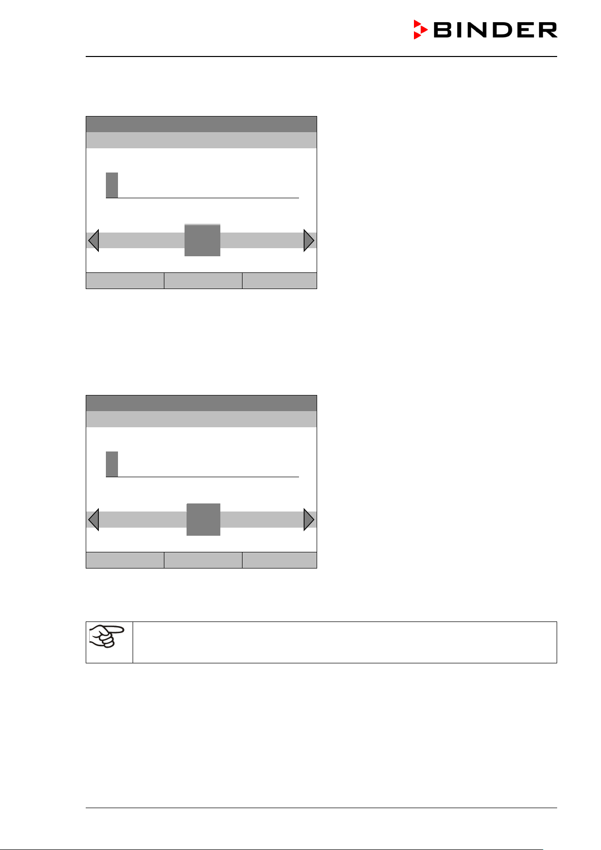
2
[°C]
Fixed value
..\ Fan speed setpoint
1
[%]
Close
Ok
Home
Temperature setting
To enter the temperature setpoint, go to Quick menu > Temperature setpoint
Fixed value
08.03.2015 05:05:06
..\ Temperature setpoint
Entry menu “Temperature setpoint”.
End Ok 0 1
3 4 5 6 7 8 9 . -
2
Select each number with the operating button and
press the operating button to confirm.
Setting range: -10 °C / 14 °F up to +100 °C / 212 °F
Press the “Ok” button to confirm.
Close Ok Home
When entering a value outside the setting range, the message “invalid value” appears. Press the operating
button to confirm with “Ok” and repeat the entry with a correct value.
Go back to the initial view with “Home” or enter the fan speed.
Fan speed setting
To enter the fan speed setpoint, go to Quick menu > Fan speed setpoint
08.03.2015 05:05:06
Entry menu “Fan speed setpoint”.
Pos1 End Ok 0
2 3 4 5 6 7 8 9 , -
1
Select each number with the operating button and
press the operating button to confirm.
Setting range: 40 % up to 100 %.
Press the “Ok” button to confirm.
When entering a value outside the setting range, the message “invalid value” appears. Press the operating
button to confirm with “Ok” and repeat the entry with a correct value.
Go back to the initial view with “Home”.
When operating the fan with less than 100 % speed, the temperature performance and the
spatial exactitude of the temperature may differ from the manufacturer’s specifications. Do
reduce the fan speed only if absolutely necessary due to special requirements.
KB / KB-UL (E4 + E6) 11/2020 page 41/149
Page 42

Fixed value
..\ Setpoints
Temperature
Fan speed
Fixed value
2
[°C]
8.3 Entering the set-points via general menu
To enter set-points via general menu, go to Menu > Setpoints
08.03.2015 05:05:06
Submenu “Setpoints”.
Select “Temperature” or “Fan speed”
and press the operating button.
Close Home
Temperature setting
To enter the temperature setpoint, go to Menu > Setpoints > Temperature
08.03.2015 05:05:06
..\ Temperature setpoint
Entry menu “Temperature setpoint”.
Pos1 End Ok 0 1
3 4 5 6 7 8 9 , -
2
Select each number with the operating button and
press the operating button to confirm.
Setting range: -10 °C / 14 °F up to +100 °C / 212 °F
Press the “Ok” button to confirm.
Close Ok Home
When entering a value outside the setting range, the message “Invalid value” appears. Press the operating
button to confirm with “Ok” and repeat the entry with a correct value.
Go back to the initial view with “Home” or enter the fan speed.
KB / KB-UL (E4 + E6) 11/2020 page 42/149
Page 43
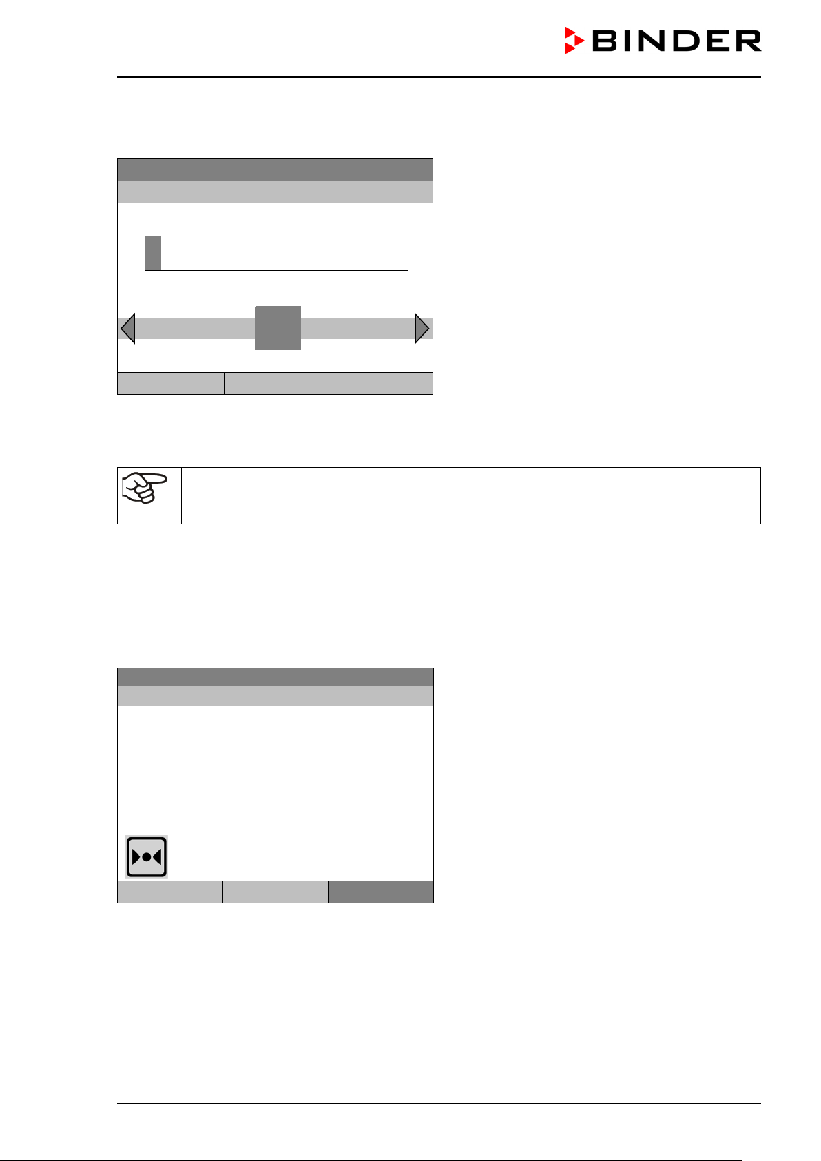
1
[%]
Fixed value
Setpoint
Actual value
25.0
25.2
100.0
Fan speed setting
To enter the fan speed setpoint, go to Menu > Setpoints > Fan speed
Fixed value
..\ Fan speed setpoint
Pos1 End Ok 0
Close Ok Home
When entering a value outside the setting range, the message “invalid value” appears. Press the operating
button to confirm with “Ok” and repeat the entry with a correct value.
Go back to the initial view with “Home”.
When operating the fan with less than 100 % speed, the temperature performance and the
spatial exactitude of the temperature may differ from the manufacturer’s specifications. Do
reduce the fan speed only if absolutely necessary due to special requirements.
1
08.03.2015 05:05:06
2 3 4 5 6 7 8 9 . -
Entry menu “Fan speed setpoint”.
Select each number with the operating button and
press the operating button to confirm.
Setting range: 40 % up to 100 %.
Press the “Ok” button to confirm.
9. Time programs
The T4.12 program controller per mits programm ing tem perature c ycles. It off ers 52 program mem ory positions with up to 100 program sections each.
To access the menu selection for time programs, select Menu > Programs > Time program
08.03.2015 05:05:06
Temperature [°C]
Fan [%]
User Quick menu Menu
Initial view.
Press the “Menu” button.
KB / KB-UL (E4 + E6) 11/2020 page 43/149
Page 44

Fixed value
..\ Menu
Controller mode
Event list
Alarms
Setpoints
Safety controller
Programs
Import/Export
Settings
Fixed value
..\ Programs
Time program
Week program
Fixed value
..\ Programs\Time programs
Start
Stop
Pause
Resume
Edit
Create
Rename
Delete
Close
Home
Fixed value
..\ Programs\Time programs
Delete all
08.03.2015 05:05:06
General menu.
Select “Programs”
and press the operating button
Close Home
08.03.2015 05:05:06
Close Home
Submenu “Programs”.
Select “Time Program”
and press the operating button
08.03.2015 05:05:06
Submenu “Time programs”.
Turn the operating button to see additional menu
items.
08.03.2015 05:05:06
Close Home
KB / KB-UL (E4 + E6) 11/2020 page 44/149
Submenu “Time programs” (next page)
Page 45

Fixed value
..\ Programs\Time programs
Start
Stop
Pause
Resume
Edit
Create
Rename
Delete
Fixed value
..\ Select program
Program0001
Program0002
Program0003
0
8.03.2015
1 2 3 4 5 6 7 8 9
9.1 Starting and running an existing time program
To start a time program, go to Menu > Programs > Time program > Start.
(You can also go to Quick menu > Time program > Start , see below).
Starting is also possible directly from the program editor (chap. 9.3.9).
In the “Control off” mode or during a running time or week program, no time program can be
started.
08.03.2015 05:05:06
Submenu “Time programs”.
Select “Start” to start an existing program
and press the operating button.
Close Home
If no program has been c reated an d save d so f ar, the message “ No program s f ound” appe ars. Pres s the
operating button to confirm with “Ok” and enter a program with “Create”.
08.03.2015 05:05:06
Submenu “Select program” (example).
Select one of the programs
and press the operating button to run the program
Close Home
Fixed value
08.03.2015 05:05:06
..\ Start date (DD.MM.YYYY)
Entry menu “Start date”.
Ins Pos1 End Ok
0
The current date is shown. For a postponed start,
enter the desired start date with the operating button.
Press the “Ok” button to confirm.
Close Ok Home
KB / KB-UL (E4 + E6) 11/2020 page 45/149
Page 46

0
Time program
08.03.2015 05:05:06
10.0
11.5
Section 20 End: 08.03.2015 08:07:44
100.0
Menu
Fixed value
08.03.2015 05:05:06
..\ Start time (HH:MM:SS)
Ins Pos1 End 1 2 3 4 5 6 7 8 9
0
Close Ok Home
Program0001 Setpoint Actual value
Temperature [°C]
Fan [%]
Entry menu “Start time”.
The current time plus 30 seconds is shown. For a
postponed start, enter the desired start time with the
operating button.
Press the “Ok” button to confirm.
Initial view (example values).
The time program is running.
User Quick menu
This symbol on the controller display indicates that a time program is running.
During a running time program, it is impossible to edit, rename or delete this program (when selecting such
a function, a corresponding message is displayed). The other program functions are available.
During a running time program, no week program can be started.
KB / KB-UL (E4 + E6) 11/2020 page 46/149
Page 47

Fixed value
..\ Quick menu
Measurement chart
Active Alarms
Temperature setpoint
Fan speed setpoint
Safety controller setpoint
Time program
Week program
Fixed value
..\ Time program
Start
Stop
Fixed value
..\ Select program
Program0001
Program0002
Program0003
To start a time program, you can also go to Quick menu > Time program > Start
08.03.2015 05:05:06
“Quick menu”.
Select “Time program”
and press the operating button
Close Home
08.03.2015 05:05:06
Submenu “Time program”.
Select “Start” to start an existing program
and press the operating button.
Close Home
The further procedure is equal to that described for the general menu.
08.03.2015 05:05:06
Submenu “Select program” (example).
Select one of the programs
and press the operating button to start the program
Close Home
KB / KB-UL (E4 + E6) 11/2020 page 47/149
Page 48
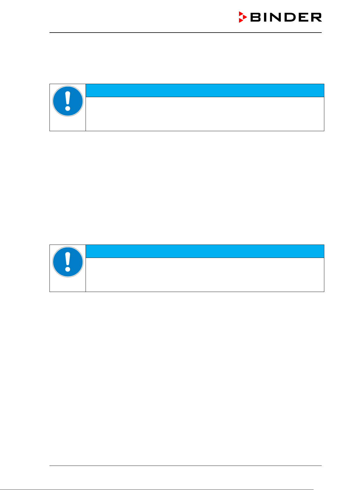
Before starting the program , check the tem perature setpoint of “Fixed value” operation
Before starting the program , check the tem perature setpoint of “Fixed value” operation
Performance after completing the progr am
The controller automatically changes to the “Fixed value” operation mode.
Before starting the program , c heck the tem peratur e setpoi nt enter ed i n the “ Fixe d value” opera tion m ode.
After end of the program, the temperature will equilibrate to this value.
NOTICE
Danger of damages by too high or too low temperature after the program ends.
Damage to the charging material.
and if necessary adapt it.
9.2 Cancelling a running time program
To cancel a running time program, go to Menu > Programs > Time program > Stop.
To cancel a running time program, you can also go to Quick menu > Time program > Stop.
The controller returns to the initial view.
Performance after manual program stop
The controller automatically changes to the “Fixed value” operation mode.
Before starting a pro gram, check the tem perature setpoint entere d in the “Fixed value” operation mode.
After cancelling the program, the temperature will equilibrate to this value.
NOTICE
Danger of damages by too low temperature after cancelling the program.
Damage to the charging material.
and if necessary adapt it.
KB / KB-UL (E4 + E6) 11/2020 page 48/149
Page 49

Fixed value
..\ Programs\Time programs
Start
Stop
Pause
Resume
Edit
Create
Rename
Delete
Fixed value
..\ Create new program
New
Based on…
9.3 Creating a new time program
For each program section you can enter a temperature set-point, the fan speed, the section’s duration, the
type of temperature transition “R” (ramp) or “S” (step) (see chap. 9.3.6), and the tolerance range.
When changing the temperature set-point, check the setting of the safety controller (chap.
17.2 and 17.3) if the safety controller has been set to “Limit” mode.
If the fan is operated with less than 100 % speed, the temperature performance and the spatial exactitude of the temperature can differ from the manufacturer’s specifications. The fan
speed rate should only be reduced if absolutely necessary to meet special requirements.
Programming is saved in case of a power failure or after turning off the chamber.
To enter a new time program, go to Menu > Programs > Time programs > Create
08.03.2015 05:05:06
Close Home
Creating a new program
Submenu “Time program”.
Select “Create"
and press the operating button.
08.03.2015 05:05:06
Submenu “Create new program”.
Select “New", to create an entirely new program, or
“Based on…”, to use an existing program for further
editing
and press the operating button.
Close Home
KB / KB-UL (E4 + E6) 11/2020 page 49/149
Page 50

Fixed value
..\ Select program
Program0001
Program0002
Program0003
Enter name
..\ Program
Fixed value
..\ Temperature controller
No.
Value
H:M:S
Ref.
Rep.
T. min
T.max
R/S
1
25.00
00:00:15
1 0 -999.00
999.00
Ramp
If you selected “Based on”, then the program selection window appears:
08.03.2015 05:05:06
Submenu “Select program” (example).
Select the desired program
and press the operating button.
Close Home
If no program has been c reated an d save d so f ar, the message “ No program s f ound” appe ars. Pres s the
operating button to confirm with “Ok” and enter a program with “Create”.
Now you can specify the name of the new time program:
08.03.2015 05:05:06
T U V W X Y Z 1 2 3 4 5 6 7 8 9
0
Entry menu “Program”.
Enter the desired start time with the operating but-
ton.
Press the “Ok” button to confirm.
Close Ok Home
The time program editor is displayed. Following the selection “Based on …”, this table for program entry
shows the values of the selected progr am. Following the s election “New" there is an empt y table, which
can be filled section by section with sample values. You can edit the displayed values.
Entering the program values for the first parameter (temperature)
A first program line is shown. This corresponds to a program section. You can now edit the values.
08.03.2015 05:05:06
KB / KB-UL (E4 + E6) 11/2020 page 50/149
Time program editor
(view with optional control outputs).
To edit the values, press the operating button, select
the desired value and press the operating button
again.
Menu
Page 51

Fixed value
..\ Temperature controller
No.
Value
H:M:S
Ref.
Rep.
T. min
T.max
R/S
1
25.00
00:00:15
1 0 -999.00
999.00
Ramp
2
25.00
00:00:15
1 0 -999.00
999.00
Ramp
3
25.00
00:00:15
1 0 -999.00
999.00
Ramp
Fixed value
..\ Temperature controller
No.
Value
H:M:S
Ref.
Rep.
T. min
T.max
R/S
1
25.00
00:00:15
1 0 -999.00
999.00
Ramp
Fixed value
..\ Program sections
Insert
Copy
Paste
Delete
To create a second progr am line (section), turn the oper ating button to the right and press it. The next
section will be added.
08.03.2015 05:05:06
Time program editor
(view with optional control outputs).
To edit the values, press the operating button, select
the desired value and press the operating button
again.
Menu
The right column for the 3 control outputs is visible only on chambers equipped with optional control outputs.
9.3.1 Section handling
08.03.2015 05:05:06
08.03.2015 05:05:06
Close
Note: When selecting „Insert“ or “Paste”, the new program section is inserted before the current section.
Time program editor.
Select a value under “No.”
and press the operating button.
Submenu “Program sections“.
Select the desired function
and press the operating button.
KB / KB-UL (E4 + E6) 11/2020 page 51/149
Page 52

Fixed value
..\ Temperature controller
[°C]
No.
Value
H:M:S
Ref.
Rep.
T. min
T.max
R/S
1
25.00
00:00:15
1 0 -999.00
999.00
Ramp
Fixed value
..\ Temperature setpoint
2
[°C]
Fixed value
..\ Temperature controller
[°C]
No.
Value
H:M:S
Ref.
Rep.
T. min
T.max
R/S
1
25.00
00:00:15
1 0 -999.00
999.00
Ramp
Fixed value
..\ Section duration
0
0:00:15
9.3.2 Temperature setpoint
08.03.2015 05:05:06
Time program editor.
Select a value under “Value”
and press the operating button.
08.03.2015 05:05:06
Entry menu “Temperature setpoint”.
Pos1 End Ok 0 1
3 4 5 6 7 8 9 , -
2
A temperature value is shown. Enter the desired
value with the operating button.
Setting range: -10 °C / 14 °F up to +100 °C / 212 °F.
Press the “Ok” button to confirm.
Close Ok
When entering a value outside the setting range, the message “invalid value” appears. Press the operating
button to confirm with “Ok” and repeat the entry with a correct value.
9.3.3 Section duration
08.03.2015 05:05:06
08.03.2015 05:05:06
Ins Pos1 End Ok 1 2 3 4 5 6 7 8 9
0
Close Ok
Time program editor.
Select a value under “H:M:S”
and press the operating button.
Entry menu “Section duration”.
A duration value is shown. Enter the desired val ue
with the operating button.
Press the “Ok” button to confirm.
KB / KB-UL (E4 + E6) 11/2020 page 52/149
Page 53

Fixed value
..\ Temperature controller
[°C]
No.
Value
H:M:S
Ref.
Rep.
T. min
T.max
R/S
1
25.00
00:00:15
1 0 -999.00
999.00
Ramp
Fixed value
..\ Reference section
1
Fixed value
..\ Temperature controller
[°C]
No.
Value
H:M:S
Ref.
Rep.
T. min
T.max
R/S
1
25.00
00:00:15
1 0 -999.00
999.00
Ramp
0
9.3.4 Repeating one or several sections within a time program
Enter the number of the ta rget section, which shal l be the start of the repeat c ycle, under “Ref.” and the
number of repeats under “Rep.”. To have sections repeated infinitely enter the number of cycles “Rep.” as
“-1”.
08.03.2015 05:05:06
08.03.2015 05:05:06
Pos1 End Ok 0 2 3 4 5 6 7 8 9 ,
1
Close Ok
Continue to enter the number of repeats:
Time program editor.
Select a value under “Ref.”
and press the operating button.
Entry menu “Reference section”.
Enter the target section number of the repeat cycle
with the operating button.
Press the “Ok” button to confirm.
Fixed value
..\ Number of repeats
Del Pos1 End Ok
1 2 3 4 5 6 7 8 9
0
Close Ok
08.03.2015 05:05:06
08.03.2015 05:05:06
Time program editor.
Select a value under “Rep.”
and press the operating button.
Entry menu “Number of repeats”.
Enter the desired number of repeats with the operat-
ing button.
Press the “Ok” button to confirm.
KB / KB-UL (E4 + E6) 11/2020 page 53/149
Page 54

Fixed value
..\ Temperature controller
[°C]
No.
Value
H:M:S
Ref.
Rep.
T. min
T.max
R/S
1
40.00
00:30:00
1 0 -999.00
999.00
Ramp
2
60.00
01:30:00
1 0 -999.00
999.00
Ramp
3
80.00
01:00:00
2
30
-999.00
999.00
Ramp
4
20.00
03:20:00
1 0 -999.00
999.00
Ramp
Fixed value
..\ Temperature controller
[°C]
No.
Value
H:M:S
Ref.
Rep.
T. min
T.max
R/S
1
25.00
00:00:15
1 0 -999.00
999.00
Ramp
-
999.00
[°C]
The following example shows a time program where the sections 2 and 3 shall be repeated 30 times:
08.03.2015 05:05:06
Time program editor.
Menu
Sections 2 and 3 will be executed in total 31 times; only then will the program continue.
9.3.5 Tolerance range
You can specify a tolerance range for each program section with different values for the tolerance minimum
and maximum. When t he actual value exceeds the gi ven threshold, the program is interrupted. This is
indicated on the dis pla y, see chap. 9.4. When the actual tem peratur e is situ ated agai n within the entered
tolerance limits, the progra m automatically cont inues. Theref ore, the duration of the progr am ma y be extended due to the programming of tolerances.
Programming of tolerances may extend program duration.
An entry of “-999” for the tolerance minimum means “minus infinite” and an entry of “999” for the tolerance
maximum means “plus infinite”. Entry of these values will never lead to program interruption.
When requesting a rapid temperature transition, we recommend not programming tolerance values in order
to enable the maximum heating-up or cooling-down speed.
Start with the minimum value:
08.03.2015 05:05:06
Time program editor.
Select a value under “T. min”
and press the operating button.
Fixed value
08.03.2015 05:05:06
..\ Tolerance range minimum temperature
2 3 4 5 6 7 8 9 , Del Ins Pos1
-
Entry menu “Tolerance range minimum temperature”.
Enter the desired value with the operating button.
Press the “Ok” button to confirm.
Close Ok
KB / KB-UL (E4 + E6) 11/2020 page 54/149
Page 55
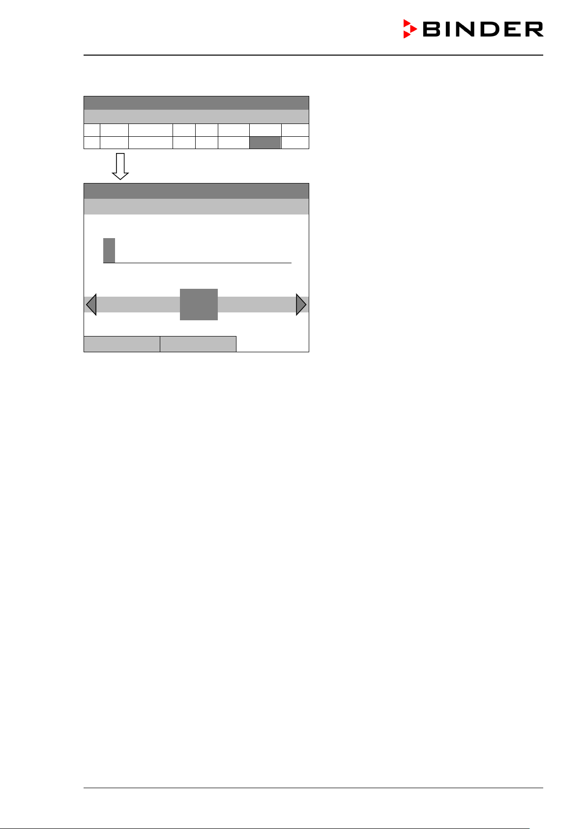
Fixed value
..\ Temperature controller
[°C]
No.
Value
H:M:S
Ref.
Rep.
T. min
T.max
R/S
1
25.00
00:00:15
1 0 -999.00
999.00
Ramp
9
99.00
[°C]
Continue to enter the maximum value:
08.03.2015 05:05:06
Fixed value
08.03.2015 05:05:06
..\ Tolerance range maximum temperature
0 1 2 3 4 5 6 7 8 , - Del Ins Pos1
9
Close Ok
Time program editor.
Select a value under “T. max”
and press the operating button.
Entry menu “Tolerance range maximum temperature”.
Enter the desired value with the operating button.
Press the “Ok” button to confirm.
KB / KB-UL (E4 + E6) 11/2020 page 55/149
Page 56

Fixed value
..\ Temperature controller
[°C]
No.
Value
H:M:S
Ref.
Rep.
T. min
T.max
R/S
1
25.00
00:00:15
1 0 -999.00
999.00
Ramp
Fixed value
..\ Ramp/step
Ramp
Step
9.3.6 Set-point ramp and set-point step modes
“Ramp” mode
The set-point of a given program section functions as the section’s target temperature. During the section’s
duration, the tem peratur e set-point gradually pass es f rom the set-point of the pre v ious progr am section to
this target set-point. The actual temperature value follows the continually changing set-point.
Programming in the “ramp” mode allows various kinds of temperature transitions:
• Gradual slow temperature changes
The set-point chan ges its value graduall y during the ent ered sect ion dura tion. T he actual tem perature
value (X) follows the continually moving set-point (W) at any time.
• Constant temperature
The initial values of two subseque nt program s ections are ident ical; so the tem perature rem ains con-
stant during the duration of the first program section.
• Sudden temperature changes
These changes occur rapidly within the minimum amount of time (minimum entry: 1 second).
“Step” mode
The set-point of a given progr am section f unctions as the sectio n’s target tem perature. At the start of the
program section, the chamber heats up or cools down with the maximum speed to reach the entered value;
and then it holds it for the remaining section time. The set-point temperature remains constant for the section’s duration.
Selecting the setting “Ramp” or “Step”:
08.03.2015 05:05:06
Time program editor.
Select a value under “R/S”
and press the operating button.
08.03.2015 05:05:06
Submenu “Ramp/step“.
Select the desired function
and press the operating button.
“Ramp” = Setpoint ramp mode selected
“Step” = Setpoint step mode selected
Close
KB / KB-UL (E4 + E6) 11/2020 page 56/149
Page 57

W/°C
t/min.
01
02
03
04
0
20
40
60
80
100
30
120
180
3
30
05
240
No.
Value
H:M:S
Ref.
Rep.
T. min
T.max
R/S
01
40.0
00:30:00
1 0 -999
+999
Ramp
02
60.0
01:30:00
1 0 -5
+5
Ramp
03
60.0
01:00:00
1 0 -2
+2
Ramp
04
80.0
01:00:00
1 0 -999
+999
Ramp
05
40.0
01:30:00
1 0 -999
+999
Ramp
W/°C
t/min.
01 02 03 04
0
20
40
60
80
100
30
120
180
380
No.
Value
H:M:S
Ref.
Rep.
T. min
T.max
R/S
01
40.0
00:30:00
1 0 -999
+999
Step
02
60.0
01:30:00
1 0 -5
+5
Step
03
80.0
01:00:00
1 0 -2
+2
Step
04
20.0
03:20:00
1 0 -999
+999
Step
Examples:
“Ramp” mode
Corresponding program table:
“Step” mode
Corresponding program table
KB / KB-UL (E4 + E6) 11/2020 page 57/149
Page 58
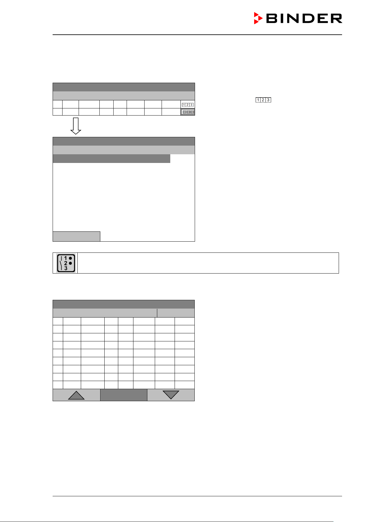
Fixed value
..\ Temperature controller
[°C]
No.
Value
H:M:S
Ref.
Rep.
T. min
T.max
R/S
1
25.00
00:00:15
1 0 -999.00
999.00
Rampe
Fixed value
..\ Zero -voltage relay outputs
Outputs 1 [Off] 2[Off] 3[Off]
Outputs 1[On] 2[Off] 3[Off]
Outputs 1[Off] 2[On] 3[Off]
Outputs 1[On] 2[On] 3[Off]
Outputs 1[Off] 2[Off] 3[On]
Outputs 1[On] 2[Off] 3[On]
Outputs 1[Off] 2[On] 3[On]
Outputs 1[On] 2[On] 3[On]
Fixed value
..\ Temperature controller
[°C]
No.
Value
H:M:S
Ref.
Rep.
T. min
T.max
R/S
1
40.00
00:30:00
1 0 -999.00
999.00
Step
2
60.00
01:30:00
1 0 -5.00
5.00
Step
3
80.00
01:00:00
1 0 -5.00
5.00
Step
4
20.00
03:20:00
1 0 -999.00
999.00
Step
5
40.00
00:30:00
1 0 -999.00
999.00
Step
6
60.00
01:30:00
1 0 -5.00
5.00
Step
7
70.00
01:00:00
1 0 -5.00
5.00
Step
8
60.00
01:00:00
1 0 -5.00
5.00
Step
9.3.7 Switching on or off the optional zero-voltage relay outputs
For chambers equipped with zero-vo ltage rela y outputs (option, c hap. 19.6), you can switch o n or off the
outputs for each program section via the program editor.
08.03.2015 05:05:06
Close
A symbol on the controller display indicates the switching state of the three zero-voltage relay outputs as soon as at least one output is switched on (example: outputs 1 + 2 turned on)
08.03.2015 05:05:06
Time program editor (with option relay outputs)
Select a field under “ ”
and press the operating button.
Submenu “Zero -voltage relay outputs”.
The possible combination of switching states are in-
dicated.
Select the desired combination of switching states
and press the operating button.“
[On] = zero-voltage relay outputs turned on
[Off] = zero-voltage relay outputs turned off
9.3.8 Calling up the next parameter
08.03.2015 05:05:06
Menu
Time program editor (example).
Press the “Menu” button.
KB / KB-UL (E4 + E6) 11/2020 page 58/149
Page 59
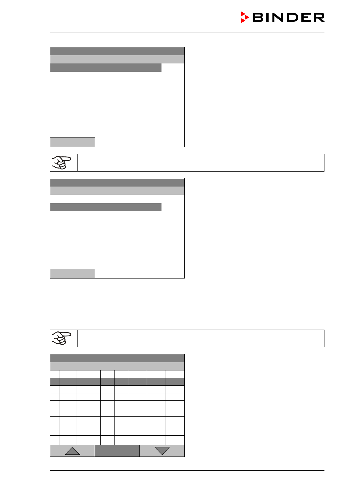
Fixed value
..\ Program menu
Select parameter
Save and exit
Save and run
Exit (without saving!)
Fixed value
..\ Program parameters
Temperature controller
Fan speed
Fixed value
..\ Fan speed
[%]
No.
Value
H:M:S
Ref.
Rep.
T. min
T.max
R/S
1
100.00
00:30:00
1 0 ***
***
Ramp
1
100.00
00:10:00
1 0 ***
***
Ramp
1
100.00
00:30:00
2 3 ***
***
Ramp
1
100.00
01:00:00
1 0 ***
***
Ramp
08.03.2015 05:05:06
Submenu “Program menu”.
Select “Select parameter”
and press the operating button.
Close
With the “Close” button, the controller returns to the time program editor.
08.03.2015 05:05:06
Submenu “Program parameters”.
Select “Fan speed main controller”
and press the operating button.
Close
Entering the set-point values for another p arameter (fan speed)
The number of progr am lines (program sections) eq ual to the number in the temper ature program is displayed. The settings of s ec tion lengt h, re peats a nd the selection „Ramp“ or „Step“ are t ak en over from the
temperature program; they are no editable in this view. The symbol “ *** ” indicates that there are no tolerance value required for the fan speed. You can enter the fan speed set-points.
If you want to insert further sections or perform any other programming, first change back to
the temperature program through Menu > Select parameter > Temperature controller.
08.03.2015 05:05:06
KB / KB-UL (E4 + E6) 11/2020 page 59/149
Time program editor (example).
To edit the values, press the operating button, select
the desired value and press the operating button
again.
Menu
Page 60

Fixed value
..\ Fan speed
[%]
No.
Value
H:M:S
Ref.
Rep.
T. min
T.max
R/S
1
100.00
00:00:15
1 0 ***
***
Ramp
1
[%]
Fixed value
..\ Temperature controller
[°C]
No.
Value
H:M:S
Ref.
Rep.
T. min
T.max
R/S
1
40.00
00:30:00
1 0 -999.00
999.00
Step
2
60.00
01:30:00
1 0 -5.00
5.00
Step
3
80.00
01:00:00
1 0 -5.00
5.00
Step
4
20.00
03:20:00
1 0 -999.00
999.00
Step
5
40.00
00:30:00
1 0 -999.00
999.00
Step
6
60.00
01:30:00
1 0 -5.00
5.00
Step
7
70.00
01:00:00
1 0 -5.00
5.00
Step
8
60.00
01:00:00
1 0 -5.00
5.00
Step
Fixed value
..\ Program menu
Select parameter
Save and exit
Save and run
Exit (without saving!)
Entering the fan speed setpoint
08.03.2015 05:05:06
Time program editor.
Select a value under “Value”
and press the operating button.
Fixed value
08.03.2015 05:05:06
..\ Fan setpoint
Entry menu “Fan setpoint”.
Pos1 End Ok 0
2 3 4 5 6 7 8 9 ,
1
A fan speed value is shown. Enter the desired value
with the operating button.
Setting range: 40 % up to 100 %
Press the “Ok” button to confirm.
Close Ok
When entering a value outside the setting range, the message “invalid value” appears. Press the operating
button to confirm with “Ok” and repeat the entry with a correct value.
9.3.9 Saving the time program and leaving the program editor
08.03.2015 05:05:06
Time program editor (example).
Press the “Menu” button.
Menu
08.03.2015 05:05:06
Submenu “Program menu”.
Select the desired function
and press the operating button.
KB / KB-UL (E4 + E6) 11/2020 page 60/149
Close
Page 61

Fixed value
..\ Exit (without saving)
Do not exit
Really exit (without saving!)
With the “Close” button, the controller returns to the time program editor.
Select parameter Changing between temperature and fan speed.
Saving the program. The controller returns to the “Time programs”
Save and exit
submenu. You can now select and start the program as described
in chap. 9.1.
Saving the program and start it. Enter the start date and time, see
Save and run
chap. 9.1. If another time or week program is running, the program
is only saved, but not started. A corresponding message is displayed.
Exit (without saving!)
Button “Close”
Attention: the pr ogram is not saved. After a sec urity question, the
controller returns to the initial view.
The controller returns to the time program editor. You can continue
programming.
Make sure that you saved the time program before leaving the program editor.
With “Exit (without saving!)” you ex it the program editor without saving the pr ogram. There is a s ecurity
question first:
08.03.2015 05:05:06
Submenu “Exit (without saving)”.
This a security question. Select the desired function
and press the operating button.
Close
If you selected “Really exit (without saving!)”, the controller goes back to the initial view.
9.4 Program interruption
You can manually inter rupt a time program ( pause), or this will autom atically occur when exceed ing the
entered tolerance range values of the corresponding program section (see chap. 9.3.5).
Manual program interruption
To interrupt a time program, go to Menu > Programs > Time programs > Pause
KB / KB-UL (E4 + E6) 11/2020 page 61/149
Page 62
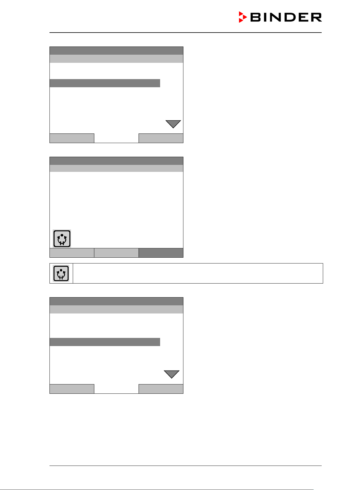
Time program
..\ Time program
Start
Stop
Pause
Resume
Edit
Create
Rename
Delete
Time program paused
Program0001
Setpoint
Actual value
10.0
11.5
Section 02 End: 08.03.2015 08:07:44
100.0
Menu
Time program paused
..\ Time program
Start
Stop
Pause
Resume
Edit
Create
Rename
Delete
08.03.2015 05:05:06
Submenu “Time program”.
Select “Pause” to interrupt the running time program
and press the operating button.
Close Home
With button “Home” the controller returns to the initial view.
08.03.2015 05:05:06
Temperature [°C]
Initial view (example values).
Fan [%]
User Quick menu
This symbol on the controller display indicates that a running time program is interrupted.
Continuing the time program after a manual interruption
08.03.2015 05:05:06
The time program is running, but halted. The final
time (in this example: 08:07:44) is running.
Submenu “Time program”.
Select “Resume” to continue the time program
and press the operating button.
Close Home
With button “Home” the controller returns to the initial view.
KB / KB-UL (E4 + E6) 11/2020 page 62/149
Page 63

Fixed value
..\ Programs\Time program
Start
Stop
Pause
Resume
Edit
Create
Rename
Delete
Close
Home
Fixed value
..\ Confirm operation
Do not delete
Really delete
9.5 Deleting a time program
To delete a time program, go to Menu > Programs > Time program > Delete or
Menu > Programs > Time program > Delete all
08.03.2015 05:05:06
Submenu “Time program”.
Select “Delete” or “Delete all” (next page)
and press the operating button
If you selected “Delete”, select then the time program to be deleted and press the operating button.
If you selected “Delete all”, all time programs will be deleted in the controller.
Before deleting there is a security question:
08.03.2015 05:05:06
Submenu “Confirm operation”.
This a security question. Select the desired function
and press the operating button.
Close Home
Go back to the initial view with “Home”.
KB / KB-UL (E4 + E6) 11/2020 page 63/149
Page 64

Fixed value
Setpoint
Actual value
25.0
25.2
100.0
Menu
Fixed value
..\ Menu
Controller mode
Event list
Alarms
Setpoints
Safety controller
Programs
Import/Export
Settings
Fixed value
..\ Programs
Time program
Week program
10. Week programs
The T4.12 program controller permits programming week programs with real-time reference. It of fers 8
week program places in total with up to 30 shift points for each week program.
To access the menu selection for week programs, select Menu > Programs > Week program
08.03.2015 05:05:06
Temperature [°C]
Fan [%]
User Quick menu
Close Home
Initial view.
Press the “Menu” button.
08.03.2015 05:05:06
General menu.
Select “Programs”
and press the operating button
08.03.2015 05:05:06
Submenu “Programs”.
Select “Week Program”
and press the operating button
Close Home
KB / KB-UL (E4 + E6) 11/2020 page 64/149
Page 65

Fixed value
..\ Programs\Week Programs
Start
Stop
Edit
Create
Rename
Delete
Delete all
Fixed value
..\ Select program
Program0004
Program0005
Day-Night
0
8.03.2015
10.1 S tarting and running an existing week program
To start a week program, go to Menu > Programs > Week program > Start
(You can also go to Qu i ck men u > Week prog ram > Start , see below).
Starting is also possible directly from the program editor (chap. 10.3.8).
In the “Control off” mode or during a running time or week program, no week program can be
started.
08.03.2015 05:05:06
Submenu “Week Programs”.
Select “Start” to start an existing week program
and press the operating button
Close Home
08.03.2015 05:05:06
Submenu “Select program” (example).
Select one of the programs
and press the operating button to run the program
Close Home
If no program has been c reated an d save d so f ar, the mess age “No progr ams f ound” appe ars. Pr ess the
operating button to confirm with “Ok” and enter a program with “Create”.
Fixed value
08.03.2015 05:05:06
..\ Start date (DD.MM.YYYY)
Entry menu “Start date”.
End Ok 0 1 2 3 5 6 7 8 9 , - Del
4
The current date is shown. For a postponed start,
enter the desired start date with the operating button.
Press the “Ok” button to confirm.
Close Ok Home
KB / KB-UL (E4 + E6) 11/2020 page 65/149
Page 66
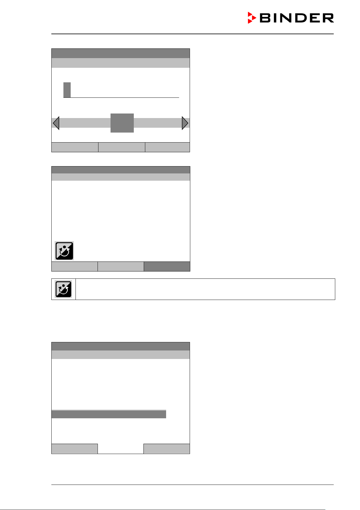
0
Week program
08.03.2015 05:05:06
Program0004
Setpoint
Actual value
15.0
15.3
Section: 0002 End: Sunday 00:00:00
100.0
Fixed value
..\ Quick menu
Measurement chart
Active Alarms
Temperature setpoint
Fan speed setpoint
Safety controller setpoint
Time program
Week program
Fixed value
08.03.2015 05:05:06
..\ Start time (HH:MM:SS)
Ins Pos1 End 1 2 3 4 5 6 7 8 9
0
Close Ok Home
Temperature [°C]
Fan [%]
Entry menu “Start time”.
The current time plus 30 seconds is shown. For a
postponed start, enter the desired start time with the
operating button.
Press the “Ok” button to confirm.
Initial view.
The week program is running.
User Quick menu Menu
This symbol on the controller display indicates that a week program is running.
During a running week program, it is impossible to e dit, rename or delete this program (when selecting
such a function, a corresponding message is displayed). The other program functions are available.
During a running week program, no time program can be started.
To start a week program, you can also go to Quick menu > Week program > Start
08.03.2015 05:05:06
“Quick menu”.
Select “Week program”
and press the operating button
Close Home
KB / KB-UL (E4 + E6) 11/2020 page 66/149
Page 67

Fixed value
..\ Week program
Start
Stop
Fixed value
..\ Select program
Program0001
Program0002
Program0003
NOTICE
08.03.2015 05:05:06
Submenu “Week program”.
Select “Start” to start an existing program
and press the operating button.
Close Home
The further procedure is equal to that described for the general menu.
08.03.2015 05:05:06
Submenu “Select program” (example).
Select one of the programs
and press the operating button to start the program
Close Home
10.2 Ca ncelling a running week program
To cancel a week program, go to Menu > Programs > Week program > Stop.
To cancel a running week program, you can also go to Quick menu > Week program > Stop.
The controller returns to the initial view.
Performance after manual program stop
The controller automatically changes to the “Fixed value” operation mode.
Before starting a pro gram, check the tem perature setpoint entere d in the “Fixed value” operation mode.
After cancelling the program, the temperature will equilibrate to this value.
Danger of damages by too high or too low temperature after cancelling the program.
Damage to the charging material.
Before starting a program, check the temperature setpoint of “Fixed value” operation and
if necessary adapt it.
KB / KB-UL (E4 + E6) 11/2020 page 67/149
Page 68

Fixed value
..\ Programs\Week programs
Start
Stop
Edit
Create
Rename
Delete
Delete all
Fixed value
..\ Create new program
New
Based on…
10.3 Creating a new week program
A week program perm its defining up to 30 sectio ns for the whole week . These sections funct ion as shift
points. A shift-point is characterized by its tim e, temperature value, and state ( active / inactive). With a
running week program, the temperature of the currently active shift point is maintained until the moment of
the next active shift point with its new temperature set-point.
Example:
No. Value Day H:M:S Activity
1 35.00 Monday 08:00:00 Active
2 40.00 Monday 10:00:00 Active
3 35.00 Monday 18:00:00 Active
4 10.00 Monday 20:00:00 Active
5 35.00 Tuesday 08:00:00 Active
... ... ... ... ...
Programming is saved in case of a power failure or after turning off the chamber.
To enter a new week program, go to Menu > Programs > Week program > Create
08.03.2015 05:05:06
Submenu “Week program”.
Select “Create"
and press the operating button.
Close Home
08.03.2015 05:05:06
Submenu “Create new program”.
Select “New", to create an entirely new program, or
“Based on”, to use an existing program for further
editing
and press the operating button.
Close Home
KB / KB-UL (E4 + E6) 11/2020 page 68/149
Page 69

Fixed value
..\ Select program
Program0004
Program0005
Day-Night
Enter name
..\ Program
Fixed value
..\ Temperature controller
[°C]
No.
Value
Day
H:M:S
Activity
1
25.00
Monday
00:00:00
Inactive
If you selected “Base d on”, then the pr ogram selection window appears:
08.03.2015 05:05:06
Submenu “Select program” (example).
Select the desired program
and press the operating button.
Close Home
If no program has been c reated an d save d so f ar, the message “ No program s f ound” appe ars. Pres s the
operating button to confirm with “Ok” and enter a program with “Create”.
Now you can specify the name of the new week program:
08.03.2015 05:05:06
T U V W X Y Z 1 2 3 4 5 6 7 8 9
0
Entry menu “Program”.
Enter the desired start time with the operating but-
ton.
Press the “Ok” button to confirm.
Close Ok Home
The week program editor is displayed. Fo llowing th e selection “Based on…”, this tab le for program entr y
shows the values of the selected progr am. Following the s election “New" there is an empt y table, which
can be filled section by section with sample values. You can then edit the displayed values.
Entering the program values for the first parameter (temperature)
A first program line is shown. This corresponds to a program section. You can now edit the values.
08.03.2015 05:05:06
KB / KB-UL (E4 + E6) 11/2020 page 69/149
Week program editor
(view with optional control outputs)
To edit the values, select the desired value and
press the operating button.
Menu
Page 70
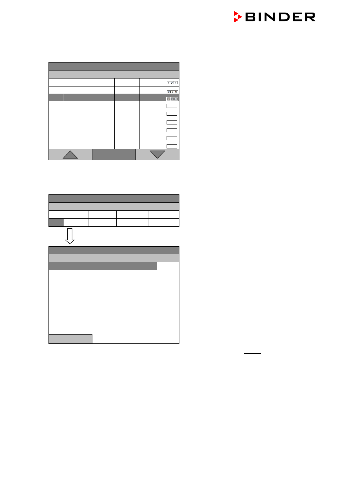
Fixed value
..\ Temperature controller
[°C]
No.
Value
Day
H:M:S
Activity
1
25.00
Monday
00:00:00
Inactive
2
25.00
Monday
00:00:00
Inactive
Fixed value
..\ Temperature controller
[°C]
No.
Value
Day
H:M:S
Activity
1
25.00
Monday
00:00:00
Inactive
Fixed value
..\ Program sections
Insert
Copy
Paste
Delete
To create a second progr am line (section), turn the oper ating button to the right and press it. The next
section will be added.
08.03.2015 05:05:06
Week program editor
(view with optional control outputs)
To edit the values, press the operating button, select
the desired value and press the operating button
again.
Menu
10.3.1 Section handling
08.03.2015 05:05:06
Week program editor.
Select a value under “No.”
and press the operating button.
08.03.2015 05:05:06
Submenu “Program sections“.
Select the desired function
and press the operating button.
Close
Note: When selecting „Insert“ or “Paste”, the new program section is inserted before the current section.
KB / KB-UL (E4 + E6) 11/2020 page 70/149
Page 71

Fixed value
..\ Temperature controller
[°C]
No.
Value
Day
H:M:S
Activity
1
25.00
Monday
00:00:00
Inactive
Fixed value
..\ Temperature setpoint
2
[°C]
Pos1 End Ok 0 1
3 4 5 6 7 8 9 , -
Close
Ok
Fixed value
..\ Temperature controller
[°C]
No.
Value
Day
H:M:S
Activity
1
25.00
Monday
00:00:00
Inactive
Fixed value
..\ Day of week
Monday
Tuesday
Wednesday
Thursday
Friday
Saturday
Sunday
Daily
10.3.2 Temperature setpoint
08.03.2015 05:05:06
Week program editor.
Select a value under “Value”
and press the operating button.
08.03.2015 05:05:06
Entry menu “Temperature setpoint”.
A temperature value is shown. Enter the desired
value with the operating button.
Setting range: -10 °C / 14 °F up to +100 °C / 212 °F.
2
Press the “Ok” button to confirm.
When entering a value outside the setting range, the message “invalid value” appears. Press the operating
button to confirm with “Ok” and repeat the entry with a correct value.
10.3.3 Day of the week
08.03.2015 05:05:06
Week program editor.
Select a field under “Day”
and press the operating button.
08.03.2015 05:05:06
Submenu “Day of week“.
Select the desired day or combination of days
and press the operating button.
Keep turning the operating button to access further
menu items.
KB / KB-UL (E4 + E6) 11/2020 page 71/149
Close
Page 72

Fixed value
..\ Day of week
Mon-Fri
Sun-Thu
Mon-Sat
Fri+Sat
Sat+Sun
Fixed value
..\ Temperature controller
[°C]
No.
Value
Day
H:M:S
Activity
1
25.00
Monday
00:00:00
Inactive
0
08.03.2015 05:05:06
Submenu “Settings” (next page).
Select the desired function
and press the operating button.
Close
10.3.4 Time of the day
Fixed value
..\ Time of day
Ins Pos1 End Ok
1 2 3 4 5 6 7 8 9
0
Close Ok
08.03.2015 05:05:06
08.03.2015 05:05:06
Week program editor.
Select a value under “H:M:S”
and press the operating button.
Entry menu “Time of day”.
Enter the desired moment of the shift-point with the
operating button.
Press the “Ok” button to confirm.
KB / KB-UL (E4 + E6) 11/2020 page 72/149
Page 73

Fixed value
..\ Temperature controller
[°C]
No.
Value
Day
H:M:S
Activity
1
25.00
Monday
00:00:00
Inactive
Fixed value
..\ Activity
Inactive
Active
Fixed value
..\ Temperature controller
[°C]
No.
Value
Day
H:M:S
Activity
1
25.00
Monday
00:00:00
Inactive
Fixed value
..\ Zero -voltage relay outputs
Outputs 1 [Off] 2[Off] 3[Off]
Outputs 1[On] 2[Off] 3[Off]
Outputs 1[Off] 2[On] 3[Off]
Outputs 1[On] 2[On] 3[Off]
Outputs 1[Off] 2[Off] 3[On]
Outputs 1[On] 2[Off] 3[On]
Outputs 1[Off] 2[On] 3[On]
Outputs 1[On] 2[On] 3[On]
10.3.5 Activity of the shift-point
Close
08.03.2015 05:05:06
Week program editor.
Select a field under “Activity”
and press the operating button.
08.03.2015 05:05:06
Submenu “Activity“.
Select the desired function
and press the operating button.
10.3.6 Switching on or off the optional zero-voltage relay outputs
08.03.2015 05:05:06
08.03.2015 05:05:06
Close
Week program editor
(view with optional control outputs)
Select a field under “
”
and press the operating button.
Submenu “Zero -voltage relay outputs”.
The possible combination of switching states are in-
dicated.
Select the desired combination of switching states
and press the operating button.“
[On] = zero-voltage relay outputs turned on
[Off] = zero-voltage relay outputs turned off
A symbol on the controller display indicates the switching state of the three zero-voltage relay outputs as soon as at least one output is switched on (example: outputs 1 + 2 turned on)
KB / KB-UL (E4 + E6) 11/2020 page 73/149
Page 74
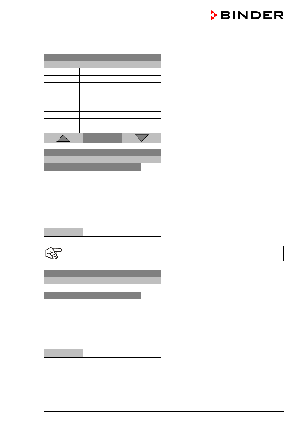
Fixed value
..\ Temperature controller
No.
Value
Day
H:M:S
Activity
1
35.00
Monday
08:00:00
Active
2
40.00
Monday
10:00:00
Active
3
35.00
Monday
18:00:00
Active
4
10.00
Monday
20:00:00
Active
5
35.00
Tuesday
08:00:00
Active
6
40.00
Tuesday
10:00:00
Active
7
35.00
Tuesday
18:00:00
Active
8
10.00
Tuesday
20:00:00
Active
Fixed value
..\ Program menu
Select parameter
Save and exit
Save and run
Exit (without saving!)
Fixed value
..\ Program parameters
Temperature controller
Fan speed
10.3.7 Calling up the next parameter
08.03.2015 05:05:06
Week program editor (example).
Press the “Menu” button.
Menu
08.03.2015 05:05:06
Close
With the „Close“ button, The controller returns to the week program editor.
Submenu “Program menu”.
Select “Select parameter”
and press the operating button.
08.03.2015 05:05:06
Submenu “Program parameters”.
Select “Fan speed”
and press the operating button.
Close
KB / KB-UL (E4 + E6) 11/2020 page 74/149
Page 75
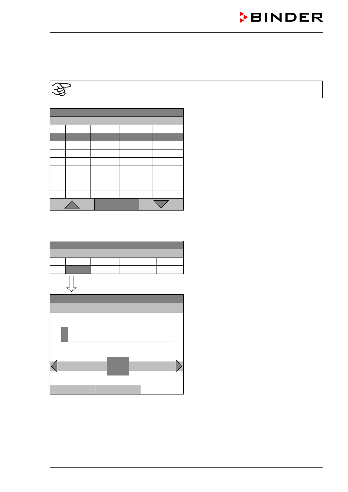
Fixed value
..\ Fan speed
[%]
No.
Value
Day
H:M:S
Activity
1
100.00
Monday
10:00:00
Active
1
100.00
Monday
12:00:00
Active
1
100.00
Monday
00:00:00
Inactive
Fixed value
..\ Fan speed
[%]
No.
Value
Day
H:M:S
Activity
1
100.00
Monday
00:00:00
Inactive
Fixed value
..\ Fan setpoint
1
[%]
Pos1 End Ok 0
2 3 4 5 6 7 8 9 ,
Close
Ok
Entering the set-point values for another p arameter (fan speed)
The number of progr am lines (program sections) eq ual to the number in the temper ature program is displayed. The settings of the s hift points (da y, time, activity) are t aken over f rom the tem perature progr am;
they are no editable in this view. You can enter the fan speed set-points.
If you want to insert further sections or perform any other programming, first change back to
the temperature program through Menu > Select parameter > Temperature controller.
08.03.2015 05:05:06
Week program editor (example).
Menu
Entering the fan speed setpoint
1
08.03.2015 05:05:06
08.03.2015 05:05:06
Week program editor.
Select a value under “Value”
and press the operating button.
Entry menu “Fan setpoint”.
A fan speed value is shown. Enter the desired value
with the operating button.
Setting range: 40 % up to 100 %
Press the “Ok” button to confirm.
When entering a value outside the setting range, the message “invalid value” appears. Press the operating
button to confirm with “Ok” and repeat the entry with a correct value.
KB / KB-UL (E4 + E6) 11/2020 page 75/149
Page 76

Fixed value
..\ Temperature setpoint
[°C]
No.
Value
Day
H:M:S
Activity
1
35.00
Monday
08:00:00
Active
2
40.00
Monday
10:00:00
Active
3
35.00
Monday
18:00:00
Active
4
10.00
Monday
20:00:00
Active
5
35.00
Tuesday
08:00:00
Active
6
40.00
Tuesday
10:00:00
Active
7
35.00
Tuesday
18:00:00
Active
8
10.00
Tuesday
20:00:00
Active
Fixed value
..\ Program menu
Select parameter
Save and exit
Save and run
Exit (without saving!)
10.3.8 Saving the week program and leaving the program editor
08.03.2015 05:05:06
Week program editor (example).
Press the “Menu” button.
Menu
08.03.2015 05:05:06
Submenu “Program menu”.
Select the desired function
and press the operating button.
Close
With the „Close“ button, The controller returns to the week program editor.
Select parameter Changing between temperature and fan speed.
Saving the program. The controller returns to the “Week programs”
Save and exit
submenu. You can now select and start the week program as described in chap. 10.1.
Saving the program and start it. Enter the start date and time, see
Save and run
chap. 10.1. If another time or week program is running, the program is
only saved, but not started. A corresponding message is displayed.
Exit (without saving!)
Attention: the progr am is not saved . After a securit y question the c ontroller returns to the initial view.
Button „Close“ The controller returns to the week program editor. You can continue
programming.
KB / KB-UL (E4 + E6) 11/2020 page 76/149
Make sure that you saved the week program before leaving the program editor.
Page 77

Fixed value
..\ Exit (without saving)
Do not exit
Really exit (without saving!)
Fixed value
..\ Programs\Week program
Start
Stop
Edit
Create
Rename
Delete
Delete all
Fixed value
..\ Confirm operation
Do not delete
Really delete
With “Exit (without saving!)” you ex it the program editor without saving the pr ogram. There is a s ecurity
question first:
08.03.2015 05:05:06
Submenu “Exit (without saving)”.
This a security question. Select the desired function
and press the operating button.
Then there is an additional security quest ion . Select
the desired function and press the operating button.
Close
If you selected “Really exit (without saving!)”, the controller goes back to the initial view.
10.4 Deleting a week program
To delete a week program, go to Menu > Programs > Week program > Delete or
Menu > Programs > Week program > Delete all
08.03.2015 05:05:06
Submenu “Week program”.
Select “Delete” or “Delete all”
and press the operating button.
Close Home
If you selected “Delete”, select then the week program to be deleted and press the operating button.
If you selected “Delete all”, all week programs will be deleted in the controller.
Before deleting there is a security question:
08.03.2015 05:05:06
Close Home
Go back to the initial view with “Home”.
KB / KB-UL (E4 + E6) 11/2020 page 77/149
Submenu “Confirm operation”.
This a security question. Select the desired function
and press the operating button.
Page 78
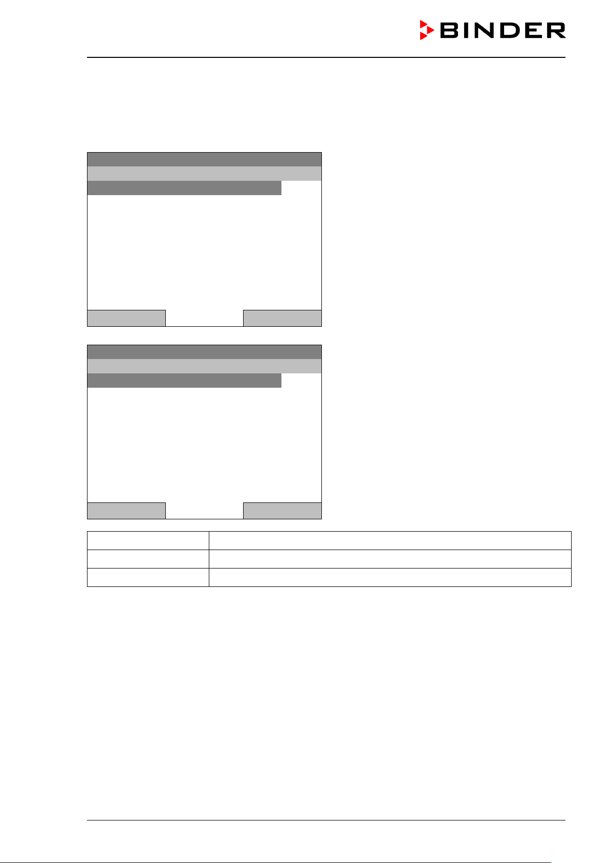
Fixed value
..\ User
Key lock
Show event list
Fixed value
..\ Key lock
Key lock O n
Automatic key lock
Password
11. Key lock
The key lock f unction serves to block the access to the co ntroller. When the “k ey lock” is activat ed, the
controller remains in the actual view and can only be changed when entering the current password.
To configure the key lock function, go to User > Key lock
08.03.2015 05:05:06
“User” menu.
Select “Key lock”
and press the operating button.
Close Home
08.03.2015 05:05:06
Submenu “Key lock”.
Select the desired function
and press the operating button.
Close Home
Key lock On The key lock is directly activated
Automatic key lock The key lock is activated automatically after a defined waiting time
Password Change password for unlocking. Factory setting: 0000
KB / KB-UL (E4 + E6) 11/2020 page 78/149
Page 79
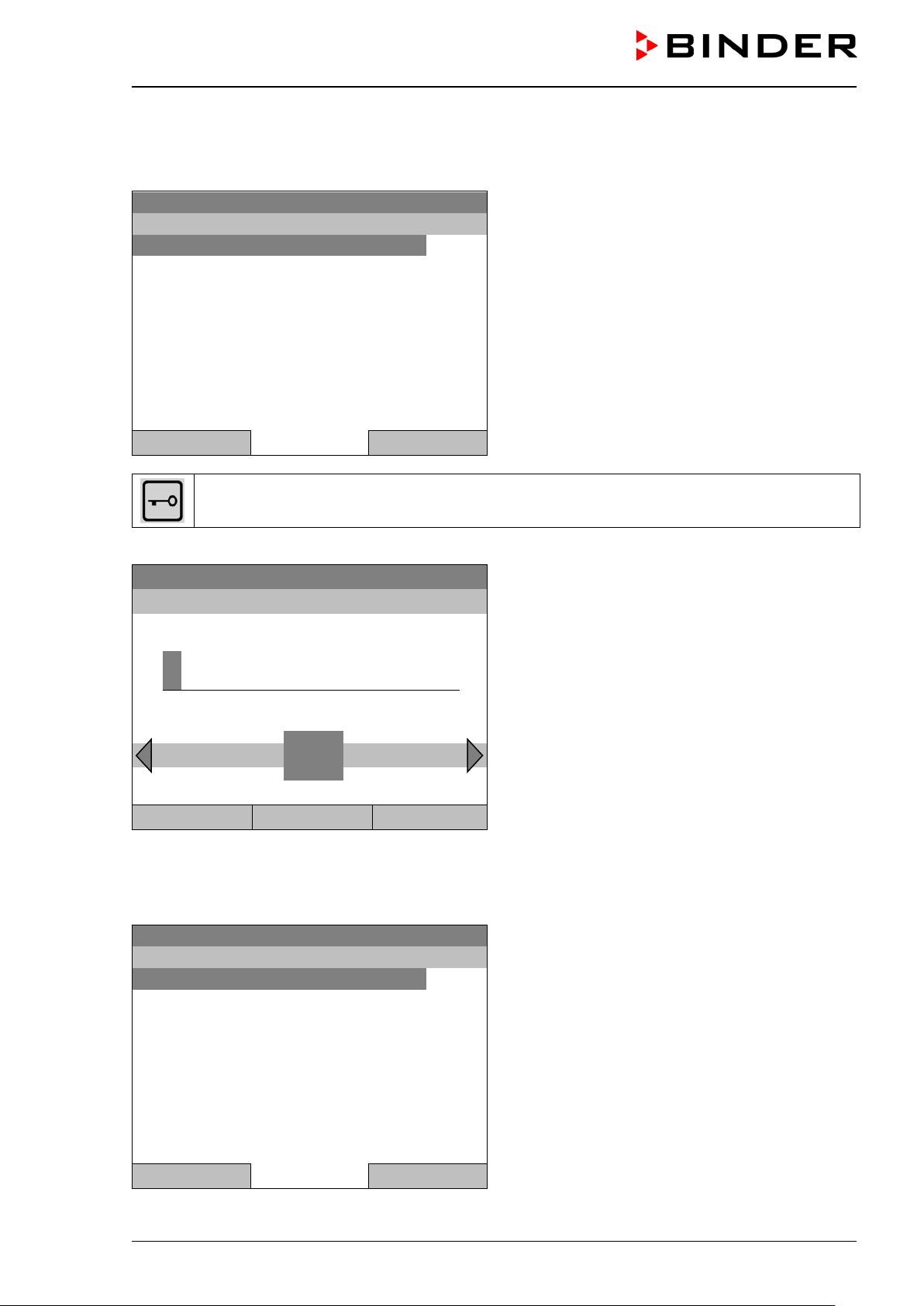
Fixed value
..\ Key lock
Key lock O n
Automatic key lock
Password
1 2 3 4 5 6 7 8 9
Fixed value
..\ Automatic key lock
Automatic key lock
Waiting time [min]
11.1 Directly activating the key lock function
To directly activate the key lock, go to User > Key loc k > Key l ock On
08.03.2015 05:05:06
Submenu “Key lock”.
Select “Key lock On” to activate the key lock function
immediately
and press the operating button.
Close Home
This symbol on the controller display indicates that the “key lock” function is activated.
The controller remains in the initial view and may be operated only after entering the current password.
Enter password
08.03.2015 05:05:06
..\ Key lock password
Ok: A B C D E F
0
Entry menu “Key lock password”.
Enter the desired password with the operating but-
ton. Factory setting is 0000
Press the “Ok” button to confirm.
Close Ok Home
11.2 Automatic key lock
To configure the automatic key lock, go to Us e r > K ey lock > Automatic key lock
08.03.2015 05:05:06
KB / KB-UL (E4 + E6) 11/2020 page 79/149
Submenu “Automatic Key lock”.
Select the desired function
and press the operating button.
Close Home
Page 80

Enter wait time [min]
..\ User\Waiting time
1
Fixed value
..\ Automatic key lock On/Off
Automatic key lock : On
Fixed value
Setpoint
Actual value
25.0
25.2
100.0
Menu
Under “Waiting time [min]” you can enter the waiting time, after which the key lock will be automatically
activated. This time starts running off after the last entry to the controller. To enter it, go to
User > Key lock > Automatic key lock > Waiting time [min]
08.03.2015 05:05:06
Pos1 End Ok 0 2 3 4 5 6 7 8 9
1
Entry menu “Waiting time”.
Enter the desired interval with the operat in g butto n.
This interval starts running off after the last action on
the controller. If the automatic key lock function is
enabled, it will become active after this time.
Factory setting: 1 minute.
Press the “Ok” button to confirm.
Close Ok Home
To activate the automatic key lock function with the pre-configured waiting time, select
User > Key lock > Automatic key lock > Automatic key lock
08.03.2015 05:05:06
Close Home
Now the waiting time starts running off.
Go back to the initial view with “Home”.
08.03.2015 05:05:06
Temperature [°C]
Fan [%]
Submenu “Automatic Key lock On/Off”.
The current setting is displayed.
To change the setting, press the operating button.
„Automatic Key lock : On“ = Automatic key lock function activated. The time set under „Waiting time” begins running off..
„Automatic Key lock : Off“ = Automatic key lock function deactivated
Initial view.
As soon as the wait ing period has expire d, the “key
lock” symbol is displayed.
User Quick menu
The controller remains in the initial view and may be operated only after entering the current password.
After further entries to th e control ler, t he waiti ng perio d begi ns runn ing aga in, sinc e the autom atic k eylock
function remains active until turning it off manually.
KB / KB-UL (E4 + E6) 11/2020 page 80/149
Page 81
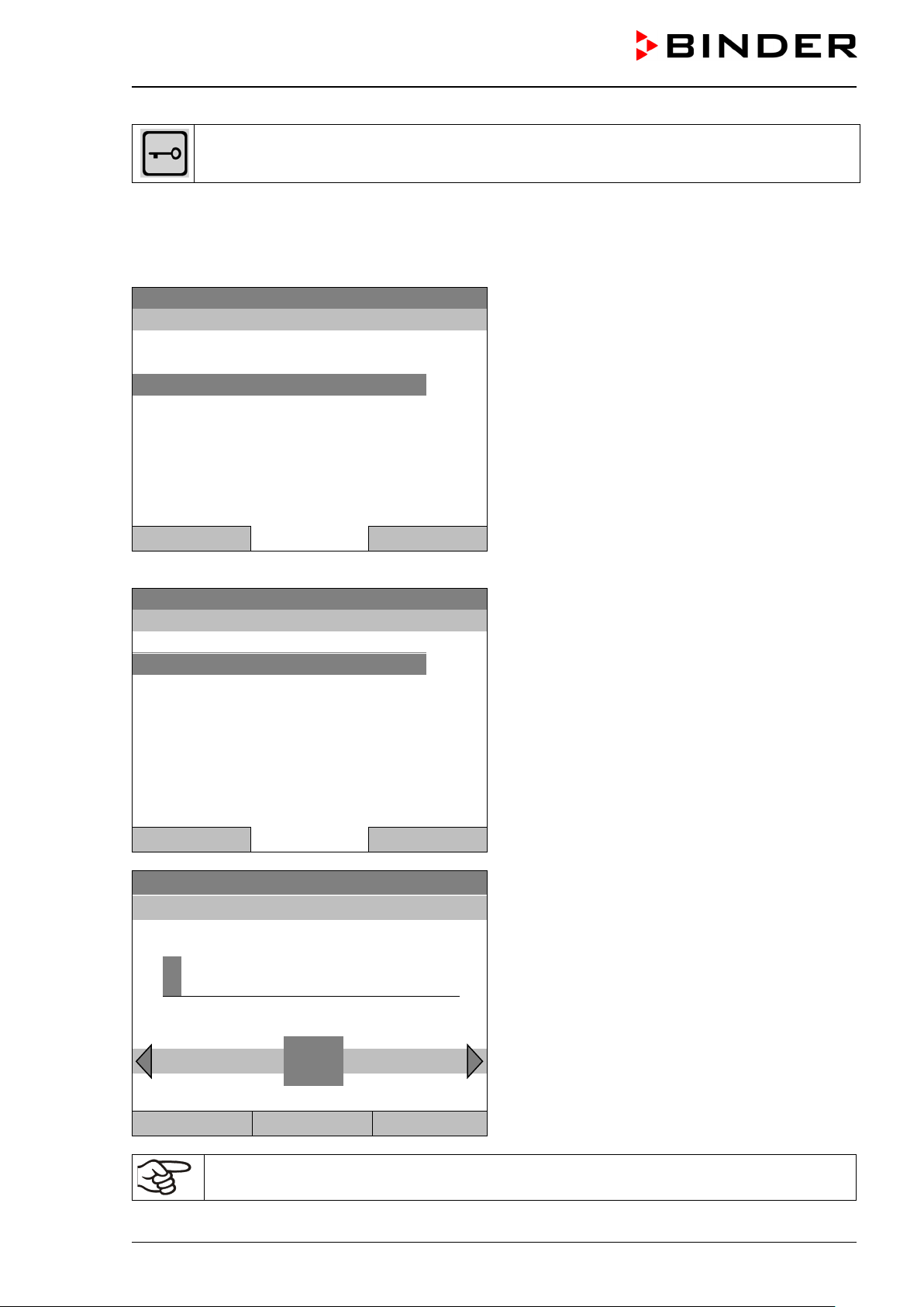
Fixed value
..\ Key lock
Key lock On
Automatic key lock
Password
Fixed value
..\ Key lock \ Change password
Do not change
Change password
Key lock password
..\ Current password
1 2 3 4 5 6 7 8 9
This symbol on the controller display indicates that the “key lock” function is activated.
11.3 Cha nging the password for unlocking the key lock
To change the password for unlocking the key lock, go to User > Key lock > Password
08.03.2015 05:05:06
Submenu “Key lock”.
Select “Password”
and press the operating button.
Close Home
A security question is displayed:
Close Home
Ok: A B C D E F
0
08.03.2015 05:05:06
08.03.2015 05:05:06
Submenu “Change password”.
To change the password,
select “Change password”
and press the operating button.
Entry menu “Current password”.
Enter the desired password with the operating but-
ton. Factory setting is 0000
Press the “Ok” button to confirm.
Close Ok Home
Keep well in mind any password modification. Without the correct password, unlocking the
key lock is impossible.
KB / KB-UL (E4 + E6) 11/2020 page 81/149
Page 82

Fixed value
..\ Settings
Setup wizard
Date and time
Sprache, Language, Langue, Idioma, Lingua
Display brightness
Temperature unit
Recording rate
Factory reset
Network settings
Fixed value
..\ Settings
Chamber configuration
12. General controller set ti ngs
In the "Settings" submenu, you can enter the date and time, select the language for the menus and the
desired temperature unit, perform the configuration for the controller’s communication functions, and reset
the controller to factory settings.
To access the "Settings" submenu, go to Menu > Settings
08.03.2015 05:05:06
Submenu “Settings”.
Turn the operating button to see additional menu
items.
Close Home
08.03.2015 05:05:06
Submenu “Settings” (next page)..
Close Home
Setup wizard Chap. 12.1
Date and time Setting date and time, chap. 12.2
Sprache, Language, Langue,
Idioma, Lingua
Selecting the controller’s menu language, chap. 12.3
Display brightness Adjusting display brightness by turning the operating button
Temperature unit Selecting the temperature unit, chap. 12.5
Recording rate Defining the recording rate for data storage, chap. 12.6
Factory reset Factory reset, chap. 12.7
Network settings Network configuration, chap. 12.8
Chamber configuration
KB / KB-UL (E4 + E6) 11/2020 page 82/149
Menu for service purpose – Display and entry of chamber data (serial
no., special application no., option object temperature, chap. 12.10
Page 83

Fixed value
..\ Date and time
Set date
Set time
12.1 Setup wizard
The setup wizard will guide you sequentially through the important menus to configure your chamber
• Menu language
• Chamber name
• Date and time
• IP address
• Subnet mask
• Network name
• Gateway
• DNS 1
• DNS 2
Then the controller returns to the initial view.
Use the setup wizard only if you want to enter all the requested information, as no item can
be skipped.
You can configure the network settings (IP address, and the following) only if the DHCP status is Off, otherwise the DHCP server would assign the network configuration.
If you try configuring any network settings while DHCP is enabled, (i.e. settings from menu item “IP Address”
on in the setup wizard), the message "DHCP enabled!” is shown. After confirming with Ok the Setup wizard
is cancelled and the controller returns to the initial display. The settings made up to then remain effective.
12.2 Date and time settings
To access the date and time settings, go to Menu > Settings > Date and time
08.03.2015 05:05:06
Submenu “Date and time”.
Select the desired function
and press the operating button.
Close Home
KB / KB-UL (E4 + E6) 11/2020 page 83/149
Page 84

Fixed value
..\ Select date (DD.MM.YYYY)
0
8.03.2015
1 2 3 4 5 6 7 8 9
Fixed value
..\ Set time (HH:MM:SS)
0
Ins Pos1 End Ok
1 2 3 4 5 6 7 8 9
Close
Ok
Home
Function “Set date”
08.03.2015 05:05:06
Ins Pos1 End Ok
0
Close Ok Home
Function “Set time”
08.03.2015 05:05:06
0
Entry menu “Select date”.
The current date is shown. If it is incorrect, enter the
correct date with the operating button.
Press the “Ok” button to confirm.
Entry menu “Set time”.
The current time is shown. If it is incorrect, enter the
correct time with the operating button.
Press the “Ok” button to confirm.
There is no autom atic switch to local light-saving tim es because this could lead to prob lems with data
seeming to be missing or being overwritten in the data base.
Go back to the “Settings” menu with “Close” or to the initial view with “Home”.
KB / KB-UL (E4 + E6) 11/2020 page 84/149
Page 85

Fixed value
..\ Sprache, Language, Langue, Idioma, Lingua
Deutsch
English
Français
Español
Italiano
Fixed value
..\ Display brightness
12.3 S electing the menu language of the T4.12 controller
The T4.12 chamber c ontroller comm unicates via a co mprehensible m enu navigation in plain text in a selectable language.
To select the desired menu language, go to
Menu > Settings > Sprache, Language, Langue, Idioma, Lingua
08.03.2015 05:05:06
Submenu “Language”.
Select the desired language
and press the operating button.
Close Home
If you selected the menu language, the controller returns to the „Settings“ menu..
Otherwise, go back to the “Settings” menu with “Close” or to the initial view with “Home”.
12.4 S etting display brightness
To select the display brightness, go to Menu > Settings > Display brightness
08.03.2015 05:05:06
Submenu “Display brightness”.
Select the desired setting by turning the
operating button.
Confirm by selecting “Save”.
Close Save Home
Go back to the “Settings” menu with “Close” or c onfirm the chang e with “Save”: T he controller returns to
the initial vie w.
KB / KB-UL (E4 + E6) 11/2020 page 85/149
Page 86

Fixed value
..\ Temperature unit
Celsius [°C]
Fahrenheit [°F]
Kelvin [K]
6
0
12.5 Cha nging the temperature unit
To select the temperature unit, go to Menu > Settings > Temperature unit
08.03.2015 05:05:06
Submenu “Temperature unit”.
Select the desired temperature unit”
and press the operating button.
Close Home
If you selected the temperature unit, the controller returns to the „Settings“ menu..
Otherwise, go back to the “Settings” menu with “Close” or to the initial view with “Home”.
12.6 De fi ni ng the data recording rate
To define the recording rate for data storage on the SD card, go to Menu > Settings > Recording rate
Fixed value
..\ Recording rate (seconds)
Ok 0 1 2 3 4 5 7 8 9 . – Del Ins
0
Close Ok Home
When entering a value smaller than 60 seconds, the message “invalid value” appears. Press the operating
button to confirm with “Ok” and repeat the entry with a correct value.
Go back to the “Settings” menu with “Close” or to the initial view with “Home”.
08.03.2015 05:05:06
Entry menu “Recording rate”.
The current recording rate is shown. Enter the de-
sired value with the operating button.
Shortest possible value: 60 seconds.
Press the “Ok” button to confirm.
Note:
After a period of 9 years, t h e c ontr o ller star ts o ver wr iti n g the ol des t val ues on the storage medium. T his is
independent of the selected storage interval and the actual operating time of the chamber. In any case, the
data can be read out at any time using the function “Export to USB drive” (chap. 13.1) and stored externally.
KB / KB-UL (E4 + E6) 11/2020 page 86/149
Page 87

Fixed value
..\ Factory reset
Do not reset
Really reset
Fixed value
..\ Network settings
Show network settings
DHCP On/Off
MAC address
IP address
Subnet mask
Chamber name
Network name
Gateway
12.7 Factory reset
The “factory reset” function allows resetting the controller configuration to the factory settings.
Risk of data loss! When resetting to factory settings, all controller settings, user data and
passwords, will be deleted. Any entered programs, the event list and stored measuring data
are NOT affected.
To access the “Factory reset” function, go to Menu > Settings > Factory reset
08.03.2015 05:05:06
Submenu “Factory reset”.
This a security question. Select the desired function
and press the operating button.
Close Home
If you selected “R eally reset” a message ask ing to restart the chamber appear s. Confirm with “OK”. The
controller returns to the initial view.
Otherwise, go back to the “Settings” menu with “Clos e” or to the initial view choosing “D o not reset” or
“Home”.
12.8 Ne twork configuration
The settings of this submenu are required for networking chambers with an Ethernet interface, e.g. to connect them with BINDER’s APT-COM™ 4 Multi Management Software.
You can display the chamber‘s IP address that has been assigned by your DHCP server or manually assign
the IP address. All necessary configurations for networking the chamber are available in this menu.
To view and configure the network settings, go to Menu > Settings > Network settings
To configure the network settings, the DHCP state must be set to off. Otherwise, the DHCPserver would assign the network configuration.
If you try to configure the net work settings with enabled DHCP state , the message “DHCP enabled!” is
shown. Confirm with „Ok“ to return to the “Network settings” menu.
08.03.2015 05:05:06
KB / KB-UL (E4 + E6) 11/2020 page 87/149
Submenu “Network settings”.
Turn the operating button to see additional menu
items.
Close Home
Page 88

Fixed value
..\ Network settings
DNS 1
DNS 2
Fixed value
..\ DHCP On/Off
DHCP : On
08.03.2015 05:05:06
Submenu “Network settings” (next page).
Close Home
Show network settings Overview of the entire network configuration
DHCP on/off Switching on and off the DHCP state
MAC address Display of the chamber’s MAC address
IP address Entering the desired IP address
Subnet mask Entering the subnet mask number
Chamber name Entering the name of the cooling incubator
Network name Entering the network name
Gateway Entering the gateway number
DNS 1 Entering the DNS 1 number
DNS 2 Entering the DNS 2 number
Set the DHCP State on/off:
22.08.2012 05:05:06
Submenu “DHCP On/Off”.
The current DHCP state is displayed. Press the op-
erating button to change it.
Then the new DHCP state is displayed
“DHCP : On” = DHCP state activated
“DHCP : Off” = DHCP state deactivated
Go back to the “Network settings” menu with “Close” or to the initial view with “Home”.
KB / KB-UL (E4 + E6) 11/2020 page 88/149
Close Home
You can only configure the following network settings if the DHCP state is set to “Off”.
Page 89

00-04-A3-55-C6-8D
1
92.168.0.100
Fixed value
..\ Subnet mask (n.n.n.n.)
2
55.255.255.0
Ins Pos1 End Ok 0 1
Display the MAC address
To identify the chamber in the Ethernet network you can display the chamber’s MAC address.
Fixed value
08.03.2015 05:05:06
..\ MAC address
Submenu “MAC address”
(example value)
The MAC address is displayed.
Close Home
Go back to the “Network settings” menu with “Close” or to the initial view with “Home”.
Enter the IP address:
Fixed value
22.08.2012 05:05:06
..\ IP address (n.n.n.n.)
Entry menu “IP address”
Ins Pos1 End Ok 0 2 3 4 5 6 7 8 9 .
1
(example value)
Enter the desired IP address with the operating but-
ton.
Press the “Ok” button to confirm.
Close Ok Home
Go back to the “Network settings” menu with “Close” or to the initial view with “Home”.
Enter the subnet mask:
22.08.2012 05:05:06
Entry menu “Subnet mask”
3 4 5 6 7 8 9 , -
2
(example value)
Enter the desired net mask with the operating but -
ton.
Press the “Ok” button to confirm.
Close Ok Home
Go back to the “Network settings” menu with “Close” or to the initial view with “Home”.
KB / KB-UL (E4 + E6) 11/2020 page 89/149
Page 90
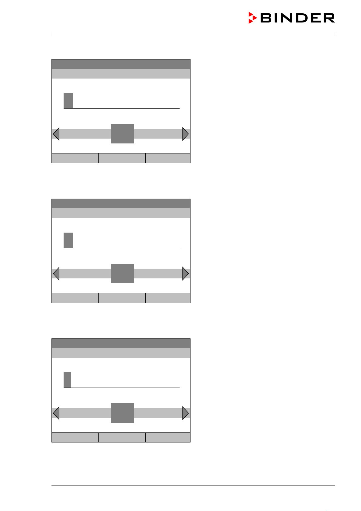
Fixed value
..\ Chamber name
K
B_E6
Fixed value
..\ Network name
K
B_E6
C D E F G H I J
L M N O P Q R
Close
Ok
Home
Fixed value
..\ Gateway (n.n.n.n.)
1
92.168.0.1
Enter the chamber name:
22.08.2012 05:05:06
Entry menu “Chamber name”
C D E F G H I J L M N O P Q R
K
(example)
Enter the desired chamber name with the operating
button.
Press the “Ok” button to confirm.
Close Ok Home
Go back to the “Network settings” menu with “Close” or to the initial view with “Home”.
Enter the network name:
22.08.2012 05:05:06
Entry menu “Network name”
K
(example)
Enter the desired network name with the operating
button.
Press the “Ok” button to confirm.
Go back to the “Network settings” menu with “Close” or to the initial view with “Home”.
Enter the default gateway:
22.08.2012 05:05:06
Pos1 End Ok 0 2 3 4 5 6 7 8 9 ,
1
Entry menu “Gateway”
(example value)
Enter the desired gateway with the operati ng butto n.
Press the “Ok” button to confirm.
Close Ok Home
Go back to the “Network settings” menu with “Close” or to the initial view with “Home”.
KB / KB-UL (E4 + E6) 11/2020 page 90/149
Page 91
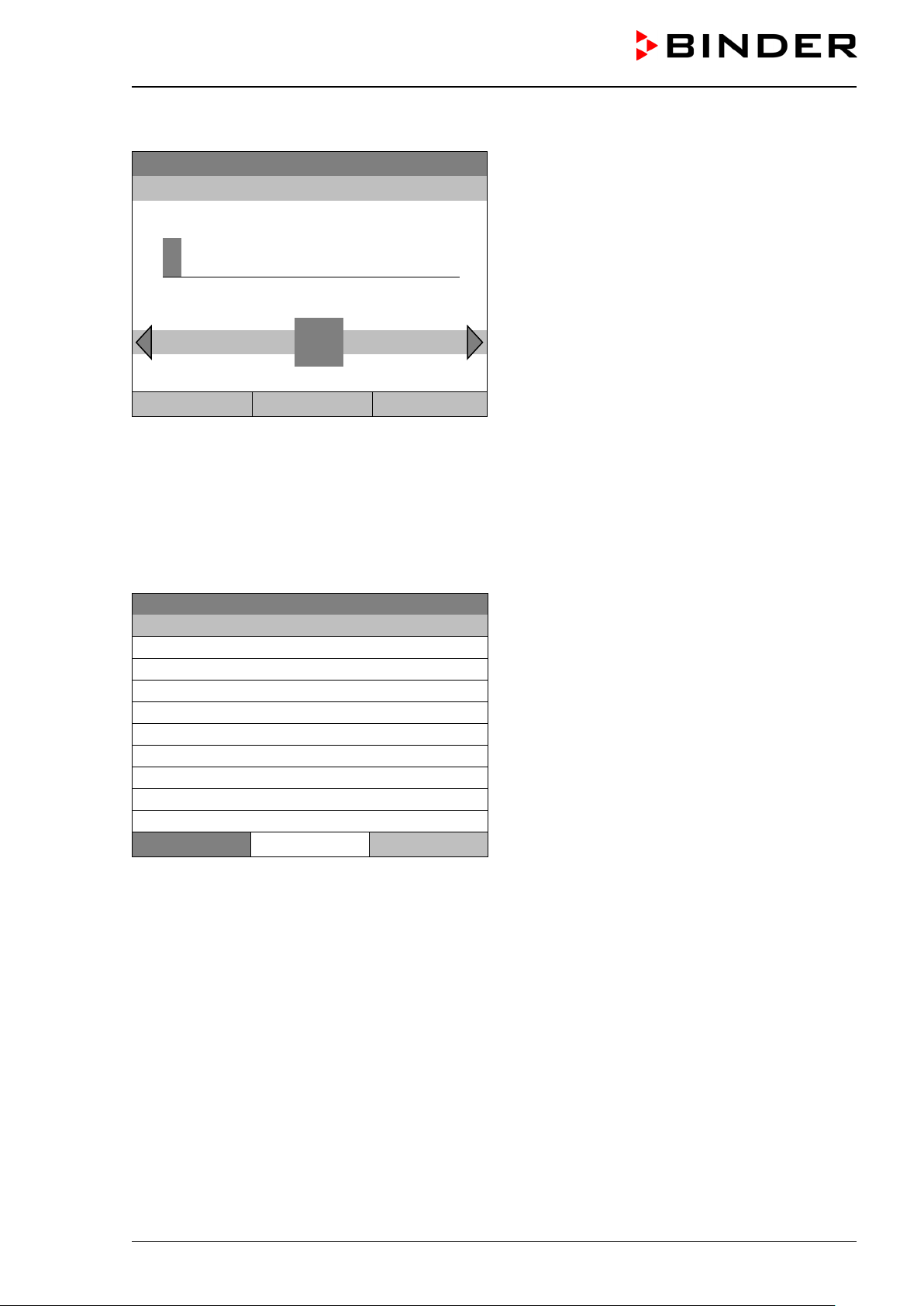
Fixed value
..\ DNS 1 (n.n.n.n.)
1
92.168.0.1
Fixed value
..\ Show network settings
DHCP
Off
MAC address
00-04-A3-55-C6-8D
IP address
192.168.0.100
Net mask
255.255.255.0
Gateway
192.168.0.1
DNS1
192.168.0.1
DNS2
0.0.0.0
Chamber name
KB_E6
BIOS name
KB_E6
Close
Enter the DNS 1 or DNS 2:
22.08.2012 05:05:06
Ins Pos1 End Ok 0
2 3 4 5 6 7 8 9 ,
1
Entry menu “DNS 1” or “DNS 2”
(example value)
Enter the desired number with the oper ati ng butto n.
Press the “Ok” button to confirm.
Close Ok Home
Go back to the “Network settings” menu with “Close” or to the initial view with “Home”.
12.9 Display of the entire network configuration
To access the overview of the complete network configuration, go to
Menu > Settings > Network settings > Show network settings
08.03.2015 05:05:06
Overview of the network configuration
(sample values)
Home
Go back to the “Network settings” menu with “Close” or to the initial view with “Home”.
12.10 Display and entry of the chamber configuration – for service purpose
Information about the chamber, such as chamber type, name, serial number, firmware version, etc. can be
viewed under Menu > System information (chap. 6.4).
To access the device configuration menu, go to Menu > Settings > Chamber configuration
This menu is password protected and only intended for service purposes.
KB / KB-UL (E4 + E6) 11/2020 page 91/149
Page 92

Fixed value
..\ Import/Export to USB drive
Export to USB drive
Import from USB drive
Fixed value
..\ Export to USB drive
Chamber status
Measurement values
Event list
Time programs
Week programs
Configuration
Adjustment
Program parameters
Fixed value
..\ Export to USB drive
System information
All
13. Data transfer via USB interface
The USB port is located in the instrument box.
To access the submenus for data transfer, go to Menu > Import/Export
08.03.2015 05:05:06
Submenu “Import/Export to USB drive”.
Select the desired type of communication via USB
port (data export or import) and press the operating
button.
Close Home
It is possible that some USB devices are not recognized due to compatibility issues. In this
case, please use a USB storage device from a different manufacturer.
13.1 E xporting data to USB drive
Insert the USB stick or the plug of your USB drive into the USB port in the instrument box.
To configure data export to USB media, go to Menu > Import/Export > Export to USB drive
08.03.2015 05:05:06
Submenu “Export to USB drive”.
Turn the operating button to see additional menu
items.
Close Home
08.03.2015 05:05:06
Close Home
KB / KB-UL (E4 + E6) 11/2020 page 92/149
Submenu “Export to USB drive” (next page)
Page 93
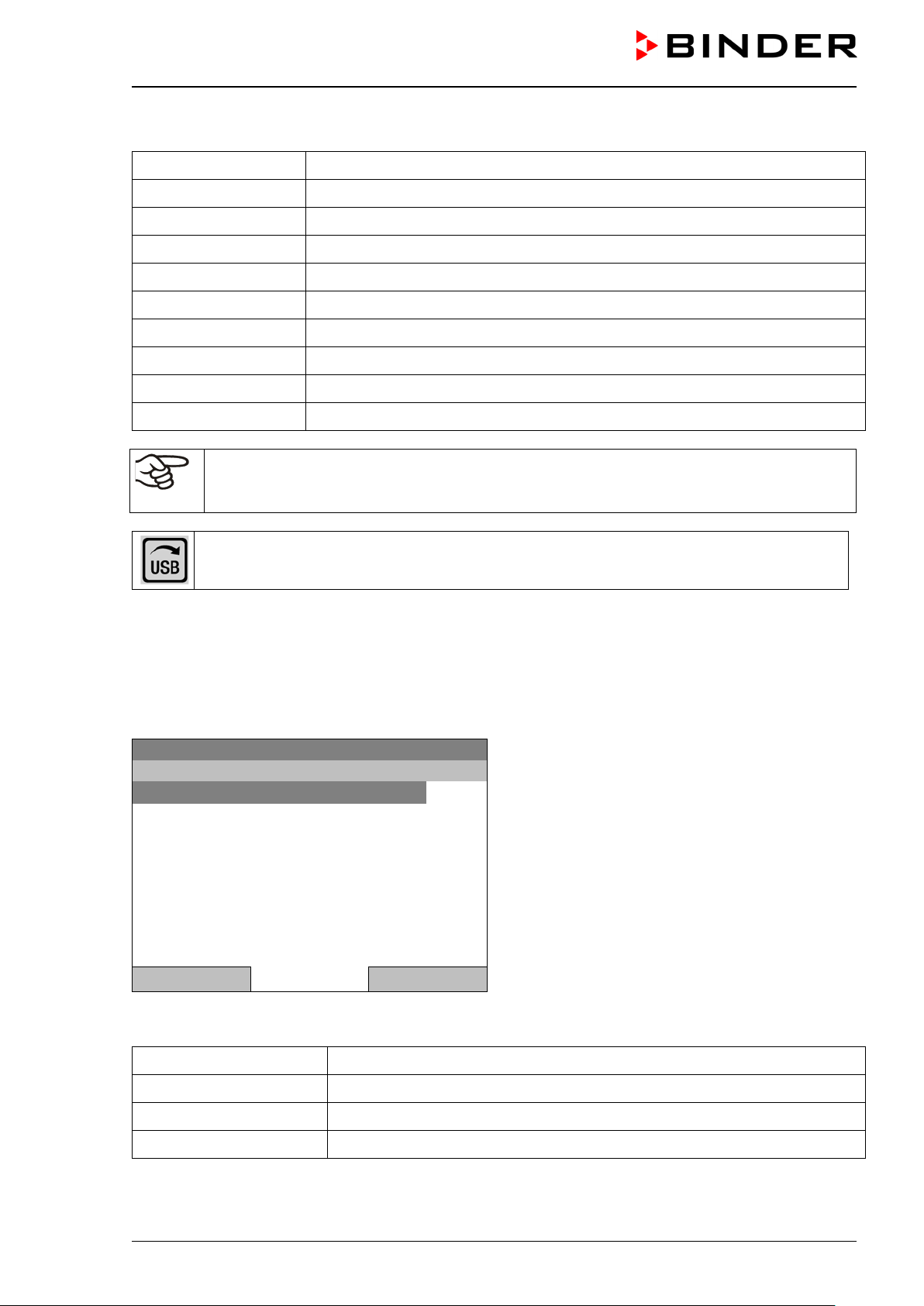
Fixed value
..\ Import from USB drive
All time programs
All week programs
Configuration
Firmware
Select the desired data type and press the operating button. Data will be written to the connected media.
Chamber status Actual chamber status, including operating mode, set-points etc.
Measurement values Measured data
Event list List of status information and errors (see chap. 15)
Time programs All stored time programs
Week programs All stored week programs
Configuration (Service only)
Adjustment Adjustment data
Program parameters (Service only)
System information
All
(Service only)
All data
If no USB device has been connected, the message “No USB device found” is displayed. It
disappears after inserting the USB stick or the plug of your USB drive into the USB port in the
instrument box.
This symbol on the controller display indicates that data are being transmitted via the USB
port.
13.2 I m por ting data from USB drive
Insert the USB stick or the plug of your USB drive into the USB port in the instrument box.
To configure data import from USB media, go to Menu > Import/Export > Import from USB drive
08.03.2015 05:05:06
Close Home
Select the desired data type and press the operating button. Data will be imported from the c onnected
media.
All time programs All stored time programs
All week programs All stored week programs
Configuration (Service only)
Firmware (Service only)
KB / KB-UL (E4 + E6) 11/2020 page 93/149
Submenu “Import from USB drive”.
Page 94
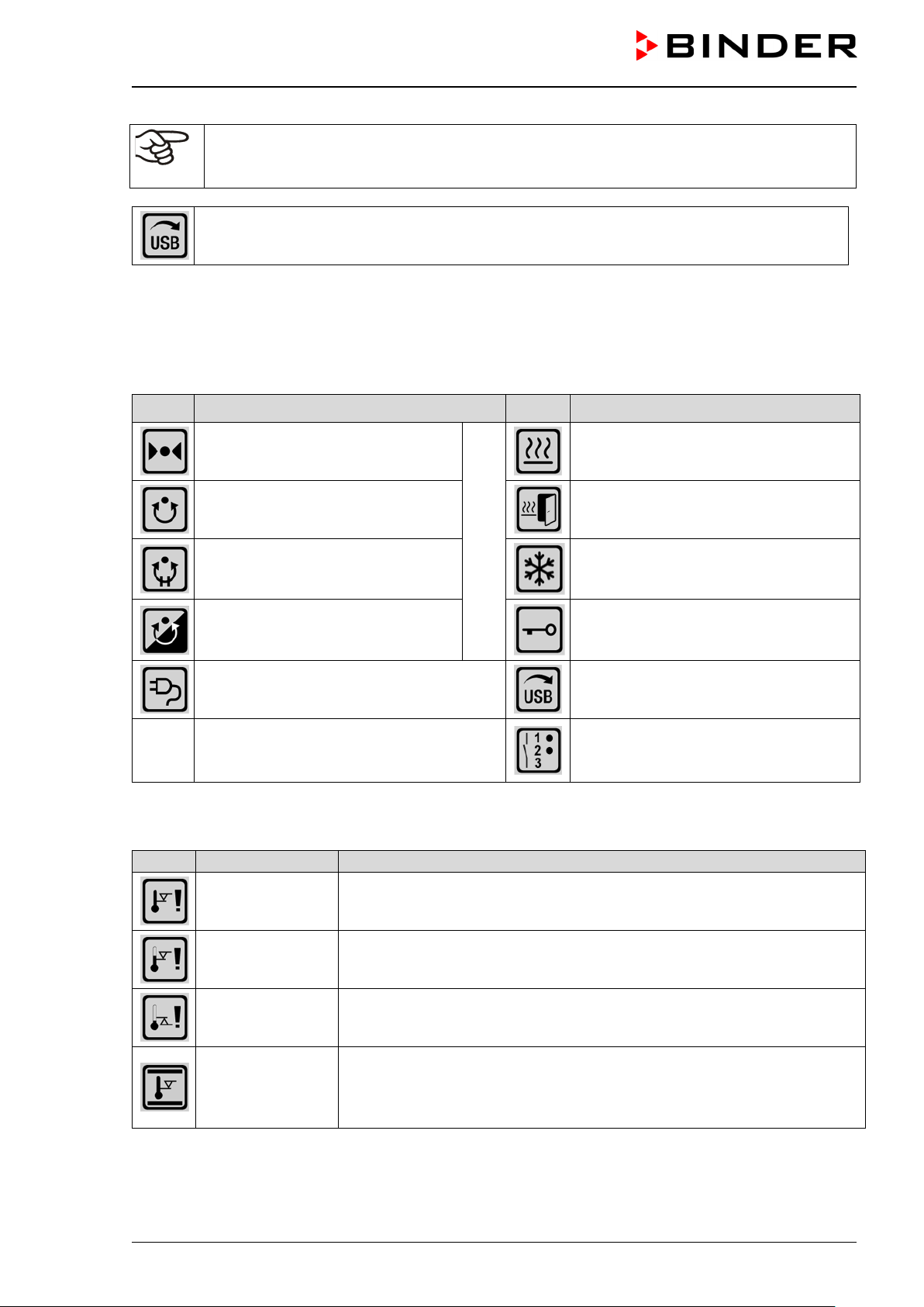
Operating modes
Icon
Alarm message
Signification
If no USB device has been connected, the message “No USB device found” is displayed. It
disappears after inserting the USB stick or the plug of your USB drive into the USB port in the
instrument box.
This symbol on the controller display indicates that data are being transmitted via the USB
port.
14. Notifications and Alarms
14.1 Notifications overview
Icon Signification Icon Signification
Fixed value operation
Time program operation
Time program interrupted
Week program operation
Interior socket (option) turned on
14.2 Alarms overview
Safety controller
overtemperature
Heating active
Door heating active
(KB / KB-UL 240 / 400 / 720)
Refrigeration active
Key lock activated
Copying data via USB
Switching state of the optional zerovoltage relay control outputs (example:
control outputs 1 + 2 switched on)
Overtemperature safety controller alarm (class 3.1): selected value of the
safety controller exceeded
Safety controller
overtemperature
Safety controller
undertemperature
Temp. range
KB / KB-UL (E4 + E6) 11/2020 page 94/149
Overtemperature safety controller alarm with option class 3.3: selected
value of the safety controller exceeded
Undertemperature safety controller alarm with option class 3.3: fallen below selected value of the safety controller
Tolerance range alarm: Having reached the set-point, the temperature deviates by more than +/- 2 °C from the set-point for more than 10 minutes,
or the temperature doesn’t reach the tolerance range within 3 hours from
turning on the chamber or closing the door
Page 95

You can activate / deactivate the buzzer in the “Alarms” submenu (chap. 14.5.3).
With an activated buzzer there is an audible alert with an alarm. You can reset it in the “Alarms” submenu
for alarm acknowledgement pressing the “Reset” button (chap. 14.4). The alarm symbol will only disappear
when the cause of the alarm has been remedied.
An optional zero-voltage relay alarm contact for temperature (chap. 19.3) is avail ab le . I t is ac tivate d in
case of the alarm m essages with t emper ature deviat ions) as well as in case of a power failure and when
turning off the main power switch.
For appropriate actions in the event of an alarm, please refer to chap. 21.3 “Troubleshooting”.
14.3 Alarm status
An alarm message can appear in 3 different states:
Status “set”
• Active alarm.
• The corresponding alarm icon is displayed in the initial view The buzzer sounds (if activated).
• The “Info” button in the initial view leads to the “Alarms” submenu for alarm acknowledgement.
• Press the “Reset” button in the “Alarms” submenu for alarm acknowledgem ent to m ute the buzzer and
confirm the alarm.
Status “acknowledged”
• Active alarm.
• The alarm was acknowledged.. The buzzer is off.
• The alarm cause is still valid. Therefore, the alarm icon remains displayed in the initial view.
• The alarm message figures in the list of active alarms.
Status “cleared”
• The alarm cause has disappeared.
• The alarm icon is not displayed any longer
• The alarm message has disappeared from the list of active alarms.
• The alarm message remains in the Event list for information.
KB / KB-UL (E4 + E6) 11/2020 page 95/149
Page 96

Fixed value
08.03.2015 15:05:02
Setpoint
Actual value
25.0
29.8
100.0
Alarm acknowledgement
..\ Home/Alarms
Safety controller overtemperature
14.4 Confirming a “set” alarm
Temperature [°C]
Initial view with overtemperature safety controller
Fan [%]
User Info Menu
08.03.2015 05:05:06
alarm.
The buzzer sounds (if not deactivated previously).
Press the “Info” button.
Submenu “Alarms” for alarm acknowledgement.
Close Reset Home
Press the “Reset” button to confirm the alarm. If there is another active “set” alarm, you can also confirm it
with the “Reset” button. Af ter confirming all active “set” alarm s, the buzzer is off, and the initial view is
displayed.
As long as an a larm is s till ac tive, i.e . as long as the a larm c ause is s till v alid, the alarm icon co ntinu es to
be displayed in the initial view.
KB / KB-UL (E4 + E6) 11/2020 page 96/149
Page 97

Fixed value
..\ Alarm
Active alarms
History
Buzzer test
Buzzer On/Off
Alarms On/Off
Fixed value
..\ Active alarms
Safety controller overtemperature
14.5 Alarm configuration and overview
To access the alarm lists and configuration menu, go to Menu > Alarms
08.03.2015 05:05:06
Submenu “Alarm”.
Select the desired function
and press the operating button.
Close Home
Active Alarms List of the active alarms (status “set” or “acknowledged”).
History List of all alarms (status “set” or “acknowledged” or “cleared”).
Buzzer test Testing the alarm buzzer, chap. 14.5.3
Buzzer On/Off Activating / deactivating the alarm buzzer, chap. 14.5.3
Alarms On/Off
Activating / deactivating the alarm functions. Off: Alarm buzzer off, no alarm
icons displayed. No alarm messages will be displayed.
14.5.1 List of active alarms
To access the overview list of active alarms, go to Menu > Alarms > Active alarms
08.03.2015 05:05:06
Submenu “Active alarms“.
All active alarms with status “set”
are listed.
or “acknowledged”,
Close Home
If no alarm is active (“set” or “acknowledged”), no message will be displayed in this window.
KB / KB-UL (E4 + E6) 11/2020 page 97/149
Page 98

Fixed value
..\ History
08.03.2015 : Messages of indicated day
14:39:48
Alarm set Safety controller overtemperature
15:03:22
Alarm cleared Safety controller overtemperature
Close
Home
Fixed value
..\ Select date (DD.MM.YYYY)
0
8.03.2015
1 2 3 4 5 6 7 8 9
Fixed value
..\ Event list
08.03.2015 : Messages of indicated day
14:17:20
Fan setpoint 50.00
14:35:12
Fan setpoint 100.00
14:39:48
Alarm set Safety controller overtemperature
14:40:19
Alarm acknowledged Safety controller overtemperature
15:03:22
Alarm cleared Safety controller overtemperature
14.5.2 History – list of all alarm s
To access the overview list of all alarms, go to Menu > Alarms > History
This list indicates the moment when an alarm was set and when cleared.
08.03.2015 15:05:06
Submenu “History” (example).
The list shows when the alarms of the current day
were triggered and when cleared. The most recent
message appears at the end of the list.
The information that an alarm has been acknowledged is shown in the event list.
When there is m ore i nf orm atio n t han o ne page, you can scrol l t he l is t in bot h dire c tions with t he operating
button.
To select a different date, select “Messages of indicated day” and press the operating button. You can enter
the desired date through an entry menu.
08.03.2015 05:05:06
Ins Pos1 End Ok
0
Entry menu “Select date”.
The current date is shown. Enter the desired date
with the operating button.
Press the “Ok” button to confirm.
Close Ok Home
The alarm list of the selected date is displayed.
The entire sequenc e of the alarm events (s et – acknowledged – cleared) is s ho wn in the event list (chap.
15).
To access the event list, go to Menu > Event list or User > View event list
08.03.2015 15:05:06
Close Home
KB / KB-UL (E4 + E6) 11/2020 page 98/149
Submenu “Event list” (example).
The events and alarm messages of the current day
are displayed. The most recent message appears at
the end of the list.
Page 99

Fixed value
..\ Buzzer test
Buzzer test: Off
Fixed value
..\ Buzzer On/Off
Buzzer activation: On
Fixed value
..\ Alarm functions On/Off
Alarm functions: On
14.5.3 Activating, deactivating, and testing the alarm buzzer
Alarm buzzer test
To access the functional test of the alarm buzzer, go to Menu > Alarms > Buzzer test
08.03.2015 05:05:06
Submenu “Buzzer test”.
The current setting is displayed.
Press the operating button to turn on or off the
buzzer for test purpose.
The modified setting is displayed
“Buzzer test: On” = Buzzer turns on
“Buzzer test: Off” = Buzzer turns off
Close Home
When turned on, th e a larm buzzer emits an inter mittent signal. To turn t his of f, change the test funct ion to
“Buzzer test: Off”.
Activating / deactivating the alarm buzzer
To activate or deactivate the alarm buzzer, go to Menu > Alarms > Buzzer On/Off
08.03.2015 05:05:06
Submenu “Buzzer On/Off”.
The current setting is displayed.
To change the setting, press the operating button.
The modified setting is displayed
“Buzzer activation: On” = Buzzer will turn on in the
event of an alarm
“Buzzer activation: Off” = Buzzer is deactivated
Close Home
14.5.4 Activating / deactivating all alarm functions
To access the alarm settings, go to Menu > Alarms > Alarms On/Off
08.03.2015 05:05:06
Submenu “Alarm functions On/Off”.
The current setting is displayed.
To change the setting, press the operating button.
The modified setting is displayed
“Alarm functions: On” = The alarm functions of the
controller are active
“Alarm functions: Off” = All alarm functions are deactivated
Close Home
Go back to the initial view with “Home”.
KB / KB-UL (E4 + E6) 11/2020 page 99/149
Page 100
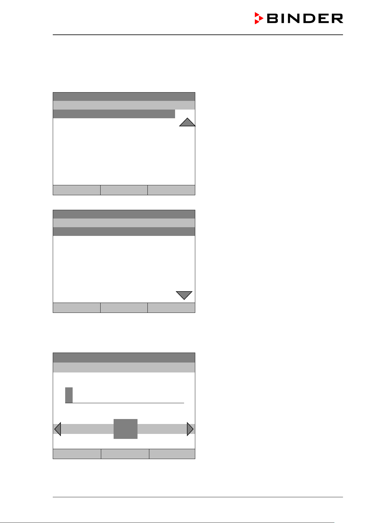
Fixed value
..\ Event list
10:11:49
Time program stopped
10:11:59
Power supply was interrupted.
10:12:05
Common controller mode OFF
10:17:20
Common controller mode ON
10:35:12
Fan setpoint 80.00
11:04:12
Fan setpoint 100.00
Fixed value
..\ Event list
08.03.2015
Messages of indicated day
09:01:59
User management disabled
09:12:05
Language loaded
09:17:20
Fan setpoint 80.00
09:35:12
Fan setpoint 100.00
10:04:12
New section time program
10:06:46
Time program started
Fixed value
..\ Select date (DD.MM.YYYY)
0
8.03.2015
1 2 3 4 5 6 7 8 9
15. Event list
The “Event list” dis pla ys st atus inf orm ation an d er rors of the curr ent da y. You can a lso acc ess t he events
of past days.
To access the event list, go to Menu > Event list or User > Show event list
08.03.2015 15:05:06
Submenu “Event list” (example).
The events of the current day are displayed. The
most recent message appears at the end of the list.
To acknowledge an activated alarm, proceed as described in chap. 14.4.
Close Reset Home
Turn the operating button to see additional data.
08.03.2015 15:05:06
Submenu “Event list” (example).
The events of the current day are displayed.
Close Reset Home
When there is m ore information than one pa ge, you can scroll the ev ent list in both directions with the
operating button.
To select a different date, select “Messages of indicated day” and press the operating button. You can enter
the desired date through an entry menu.
08.03.2015 05:05:06
Ins Pos1 End Ok
0
Entry menu “Select date”.
The current date is shown. Enter the desired date
with the operating button.
Press the “Ok” button to confirm.
Close Ok Home
The event list of the selected date is displayed.
KB / KB-UL (E4 + E6) 11/2020 page 100/149
 Loading...