

Page 1

BiPAC 7800(N)
(802.11n) Dual WAN
ADSL2+ Firewall Router
User Manual
Version released: 1.06f
Last revised on Dec 27 2011
Page 2

Table of Contents
Chapter 1: Introduction ............................................................................................................. 1
Introduction to your Router ............................................................................................ 1
Features ....................................................................................................................... 2
Hardware Specications ............................................................................................... 5
Chapter 2: Installing the Router ................................................................................................ 6
Package Contents ......................................................................................................... 6
Important note for using this router ............................................................................... 7
Device Description ........................................................................................................ 8
The Front LEDs ..................................................................................................... 8
The Rear Ports ..................................................................................................... 9
Cabling ........................................................................................................................ 10
Chapter 3: Basic Installation .................................................................................................. 11
Connecting Your Router .............................................................................................. 12
Network Conguration ................................................................................................. 13
Factory Default Settings .............................................................................................. 21
Information from your ISP ......................................................................................... 22
Chapter 4: Conguration ......................................................................................................... 23
Easy Sign-On (EZSO) ................................................................................................. 23
Conguration via Web Interface .................................................................................. 26
Quick Start .................................................................................................................. 27
ADSL Mode ......................................................................................................... 27
EWAN Mode ........................................................................................................ 38
Basic Conguration Mode ........................................................................................... 44
Status .................................................................................................................. 44
WAN – Main Port (ADSL) .................................................................................... 45
PPPoE Connection (ADSL) ............................................................................ 45
PPPoA Connection (ADSL) ............................................................................ 47
MPoA Connection (ADSL) .............................................................................. 48
IPoA Connections (ADSL) .............................................................................. 50
Pure Bridge Connections (ADSL) ................................................................... 51
WAN – Main Port (EWAN) ................................................................................... 52
PPPoE (EWAN) .............................................................................................. 52
Obtain IP Address Automatically (EWAN) ....................................................... 53
Fixed IP Address (EWAN) .............................................................................. 54
Pure Bridge (EWAN) ....................................................................................... 55
WLAN (only for BiPAC 7800N) ............................................................................ 56
Advanced Conguration Mode .................................................................................... 61
Status .................................................................................................................. 61
ADSL .............................................................................................................. 63
WAN Statistics ................................................................................................ 64
Page 3

ARP ................................................................................................................ 65
DHCP ............................................................................................................. 66
System Log..................................................................................................... 67
Firewall Log .................................................................................................... 68
UPnP Portmap ................................................................................................ 68
PPTP Satus .................................................................................................... 69
Conguration ....................................................................................................... 70
LAN ................................................................................................................ 71
Ethernet ................................................................................................... 71
IP Alias .................................................................................................... 71
IPv6 Autocong ....................................................................................... 72
Wireless (only for BiPAC 7800N) ............................................................. 74
Wireless Security (only for BiPAC 7800N) ............................................... 77
WPS (only for BiPAC 7800N) .................................................................. 79
DHCP Server ........................................................................................... 91
WAN - Wide Area Network ............................................................................. 93
WAN Interface ......................................................................................... 93
WAN Prole ............................................................................................. 96
ADSL Mode ............................................................................................111
System ......................................................................................................... 112
Time Zone ............................................................................................. 112
Firmware Upgrade ................................................................................. 113
Backup / Restore ................................................................................... 114
Restart ................................................................................................... 115
User Management ................................................................................. 116
Syslog .................................................................................................... 118
Diagnostics Tools ................................................................................... 119
Firewall ......................................................................................................... 120
Packet Filter .......................................................................................... 120
Ethernet MAC Filter ............................................................................... 122
Wireles MAC Filter................................................................................. 123
Intrusion Detection ................................................................................ 124
Block WAN Ping .................................................................................... 124
URL Filter .............................................................................................. 125
VPN .............................................................................................................. 127
PPTP ..................................................................................................... 127
PPTP Account ....................................................................................... 129
PPTP Client ........................................................................................... 130
QoS - Quality of Service ............................................................................... 131
Virtual Server ................................................................................................ 135
Port Mapping ......................................................................................... 136
DMZ ....................................................................................................... 137
One-to-One NAT .................................................................................... 138
Page 4

ALG ....................................................................................................... 139
Time Schedule .............................................................................................. 141
Advanced...................................................................................................... 142
Static Route ........................................................................................... 142
Static ARP ............................................................................................. 143
Static DNS ............................................................................................. 144
Dynamic DNS ........................................................................................ 145
VLAN ..................................................................................................... 146
Device Management .............................................................................. 148
IGMP ..................................................................................................... 155
MLD ....................................................................................................... 155
SNMP Access Control ........................................................................... 156
Remote Access...................................................................................... 157
Web Access Control .............................................................................. 158
Save Conguration to Flash ...................................................................................... 159
Restart....................................................................................................................... 160
Chapter 5: Troubleshooting .................................................................................................. 161
Appendix: Product Support & Contact .................................................................................. 162
Page 5

Chapter 1: Introduction
Introduction to your Router
Thank you for purchasing BiPAC 7800(N) Router. Your new router is an all-in-one unit that combines
an ADSL modem, ADSL2/2+ router and Ethernet network switch to provide everything you need to
get the machines on your network connected to the Internet over an ADSL broadband connection.
BiPAC 7800(N) router complies with ADSL2+ standards for deployment worldwide and supports
downstream rates of up to 24 Mbps and upstream rates of up to 1 Mbps. Designed for small ofce,
home ofce and residential users, the router enables even faster Internet connections. You can
enjoy ADSL services and broadband multimedia applications such as interactive gaming, video
streaming and real-time audio much easier and faster than ever before.
BiPAC 7800(N) supports PPPoA (RFC 2364 – PPP (Point-to-Point Protocol) over ATM Adaptation
Layer 5), RFC 1483 encapsulation over ATM (bridged or routed), PPP over Ethernet (RFC 2516)
to establish a connection with your ISP. Your new router also supports VC-based and LLC-based
multiplexing.
The perfect solution for connecting a small group of PCs to a high-speed broadband Internet connection,
BiPAC 7800(N) allows multiple users to have high-speed Internet access simultaneously.
Your new router also serves as an Internet rewall, protecting your network from access by outside
users. Not only does it provide a natural rewall function with Network Address Translation (NAT), it
also provides rich rewall features to secure your network. All incoming data packets are monitored
and ltered. You can also congure your new router to block internal users from accessing the
Internet.
BiPAC 7800(N) provides two levels of security support. First, it masks LAN IP addresses making
them invisible to outside users on the Internet, so it is much more difcult for a hacker to target a
machine on your network. Second, it can block and redirect certain ports to limit the services that
outside users can access. To ensure that games and other Internet applications run properly, you
can open specic ports for outside users to access internal services on your network.
The Integrated DHCP (Dynamic Host Control Protocol) client and server services allow multiple
users to get IP addresses automatically when the router boots up. Simply set local machines as a
DHCP client to accept a dynamically assigned IP address from the DHCP server and reboot. Each
time a local machine is powered up; the router recognizes it and assigns an IP address to instantly
connect it to the LAN.
For advanced users, Virtual Service (port mapping) functions allow the product to provide limited
visibility to local machines with specic services for outside users. For instance, a dedicated web
server can be connected to the Internet via the router and then incoming requests for web pages
that are received by the router can be rerouted to your dedicated local web server, even though the
server now has a different IP address.
Virtual Server can also be used to re-task services to multiple servers. For instance, you can set the
router to allow separated FTP, Web, and Multiplayer game servers to share the same Internet-visible
IP address while still protecting the servers and LAN users from hackers.
1
Page 6

Features
Express Internet Access
The router complies with ADSL worldwide standards. It supports downstream rate up to 12/24
Mbps with ADSL2/2+, 8Mbps with ADSL. Users enjoy not only high-speed ADSL services but also
broadband multimedia applications such as interactive gaming, video streaming and real-time audio
much easier and faster than ever. It is compliant with Multi-Mode standard (ANSI T1.413, Issue 2;
G.dmt (ITU G.992.1); G.lite (ITU G.992.2); G.hs (ITU G994.1); G.dmt.bis (ITU G.992.3); G.dmt.bis.
plus (ITU G.992.5)).
EWAN
BiPAC 7800(N) EWAN port provides user an alternative means to connect to Cable Modems, VDSL,
ber optic lines and PON besides using ADSL for internet connection. If one uses ADSL to connect
to the internet, EWAN can act as the 5th Ethernet port of the LAN. This alternative provides users
with more exibility & a faster way to get online.
IPv6 Supported
Internet Protocol version 6 (IPv6) is a version of the Internet Protocol that is designed to succeed
IPv4.
IPv6 has a vastly larger address space than IPv4. This results from the use of a 128-bit address,
whereas IPv4 uses only 32 bits. The new address space thus supports 2128 (about 3.4×1038)
addresses. This expansion provides exibility in allocating addresses and routing trafc and eliminates
the primary need for network address translation (NAT), which gained widespread deployment as an
effort to alleviate IPv4 address exhaustion.
IPv6 also implements new features that simplify aspects of address assignment (stateless address
autoconguration) and network renumbering (prex and router announcements) when changing
Internet connectivity providers. The IPv6 subnet size has been standardized by xing the size of the
host identier portion of an address to 64 bits to facilitate an automatic mechanism for forming the
host identier from Link Layer media addressing information (MAC address).
Fast Ethernet Switch
A 4-port 1000Mbps fast Ethernet switch is built in with automatic switching between MDI and MDI-X.
An Ethernet straight or crossover cable can be used directly for auto detection.
Multi-Protocol to Establish a Connection
It supports PPPoA (RFC 2364 - PPP over ATM Adaptation Layer 5), RFC 1483 encapsulation
over ATM (bridged or routed), PPP over Ethernet (RFC 2516), and IPoA (RFC1577) to establish a
connection with the ISP. The product also supports VC-based and LLC-based multiplexing.
PPP over Ethernet (PPPoE)
BiPAC 7800(N) provides an embedded PPPoE client function to establish a connection. You get
greater access speed without changing the operation concept, while sharing the same ISP account
and paying for one access account. No PPPoE client software is required for the local computer.
2
Page 7

Automatic Reconnect and Disconnect Timeout (Idle Timer) functions are also provided.
Universal Plug and Play (UPnP) and UPnP NAT Traversal
This protocol is used to enable simple and robust connectivity among stand-alone devices and PCs
from many different vendors. It makes network simple and affordable for users. UPnP architecture
leverages TCP/IP and the Web to enable seamless proximity networking in addition to control and
data transfer among networked devices. With this feature enabled, users can now connect to Net
meeting or MSN Messenger seamlessly.
Network Address Translation (NAT)
Allows multi-users to access outside resources such as the Internet simultaneously with one IP
address/one Internet access account. Many application layer gateway (ALG) are supported such as
web browser, ICQ, FTP, Telnet, E-mail, News, Net2phone, Ping, NetMeeting, IP phone and others.
Domain Name System (DNS) Relay
It provides an easy way to map the domain name (a friendly name for users such as www.yahoo.
com) and IP address. When a local machine sets its DNS server with this router’s IP address, every
DNS conversion request packet from the PC to this router will be forwarded to the real DNS in the
outside network.
Dynamic Domain Name System (DDNS)
The Dynamic DNS service allows you to alias a dynamic IP address to a static hostname. This
dynamic IP address is the WAN IP address. For example, to use the service, you must rst apply
for an account from a DDNS service like http://www.dyndns.org/. More than 5 DDNS servers are
supported.
Virtual Server
Users can specify some services to be visible from outside users. The router can detect incoming
service requests and forward either a single port or a range of ports to the specic local computer
to handle it. For example, a user can assign a PC in the LAN acting as a WEB server inside and
expose it to the outside network. Outside users can browse inside web servers directly while it is
protected by NAT. A DMZ host setting is also provided to a local computer exposed to the outside
network, Internet.
Rich Packet Filtering
Not only lters the packet based on IP address, but also based on Port numbers. It will filter packets
from the Internet and vice versa, in addition to providing a higher level of security control.
Dynamic Host Conguration Protocol (DHCP) Client and Server
In the WAN site, the DHCP client can get an IP address from the Internet Service Provider (ISP)
automatically. In the LAN site, the DHCP server can allocate a range of client IP addresses and
3
Page 8

distribute them including IP address, subnet mask as well as DNS IP address to local computers. It
provides an easy way to manage the local IP network.
802.11n Wireless AP with WPA Support
With an integrated 802.11n Wireless Access Point in the router, the device delivers up to 6 times
faster speeds and 3 times farther range than an 802.11b/g wireless network. It supports a fast data
transfer rate up to 300Mbps and is fully compatible with 802.11b/11g equipments. The supported
features of Wi-Fi Protected Access (WPA-PSK/ WPA2-PSK) and Wired Equivalent Privacy (WEP)
enhance the security level of data protection and access control via Wireless LAN. The router also
supports Wi-Fi Protected Setup (WPS) that features the establishment of a secured wireless network.
The built-in Wireless Distribution System (WDS) also facilitates the exibility for wireless network
expansion without the need for any external wires or cables.
Web based GUI
It supports web based GUI for conguration and management. It is user-friendly and comes with online help. It also supports remote management capability for remote users to congure and manage
this product.
Firmware Upgradeable
Device can be upgraded to the latest rmware through the WEB based GUI.
4
Page 9

Hardware Specications
Physical Interface
• WLAN: 3 x 2 dbi detachable antennae (BiPAC 7800NA only)
• DSL: ADSL port
• EWAN: RJ-45 Ethernet port for connecting to ADSL / Cable / FTTH / VDSL device
• Ethernet: 4-port 10/100/1000M auto-crossover (MDI / MDI-X) Switch
• Factory default reset button
• WPS push button (BiPAC 7800NA only)
• Power jack
• Power switch
5
Page 10
Chapter 2: Installing the Router
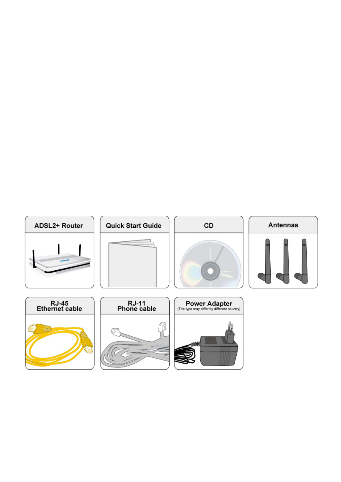
Package Contents
BiPAC 7800(N) (802.11n) Dual WAN ADSL2+ Firewall Router
CD containing the online manual
RJ-11 ADSL/Telephone cable
Ethernet (RJ-45) cable
Three 2dBi detachable antennas (Wireless model only)
Power adapter
Quick Start Guide
Splitter / Microlter (Optional)
6
Page 11
Important note for using this router
7
Page 12

Device Description
The Front LEDs
LED Meaning
Lit orange when WAN port fails to get IP address.
1 Internet
2 DSL
Wireless / WPS
3
(only available for
BiPAC 7800N)
4 EWAN
Ethernet port
5
1X - 4X
(RJ-45 connector)
Lit green when WAN port gets IP address.
Lit off when device in bridged mode or ADSL connection not present.
Lit Green when the device is successfully connected to an ADSL
DSLAM. (“line sync”).
Lit green when a wireless connection is established.
Flash orange when WPS conguration is in progress. However, if
WPS fails the LED will only lit for 1 min before goes off.
Flash green when data is sent / received.
Lit orange when connected to a broadband connection device.
Lit orange for 10/100Mbps.
Blinking when data is Transmitted / Received.
Lit orange when one of LAN ports is connected to an Ethernet
device.
Lit green when the speed of transmission hits 1000Mbps; Lit orange
when the speed of transmission hits 10/100Mbps.
Blink when data is being Transmitted / Received.
When the device is booting, the green light will lit while the orange
light will ash.
6 Power
When the system is ready, it will lit green.
Lit orange when the device fails to boot or when the device is in
emergency mode.
8
Page 13

The Rear Ports
Port Meaning
1 Power Switch Power ON/OFF switch.
2 Power Connect it with the supplied power adapter.
3 RESET
WPS
4
(only for BiPAC 7800N)
5 Giga Ethernet
6 EWAN
7 DSL
Antenna
8
(BiPAC 7800N only)
Press more than 5 seconds to restore the device to its default
mode.
By controlling the pressing time, users can achieve two
different effects:
(1)WPS: Press less than 5 seconds until WPS LED ashes
orange to trigger WPS function. But if WPS service is disabled,
this short time press does nothing.
(2) Wireless ON/OFF button: Press over 5 seconds to switch
on wireless function and the Wireless/WPS LED will lit green.
Press over 5 seconds again to disable wireless function and
the Wireless/WPS LED is off.
Connect to a PC or an ofce/home network of 10Mbps,
100Mbps or 1000Mbps using the provided RJ-45 Ethernet
cables.
WAN 10/100Mbps Ethernet port (with auto crossover support).
Connect to Cable Modem, VDSL, Fiber Modem or PON optic
lines with your RJ-45 cable.
Connect this port to the ADSL/telephone network with the RJ-
11 cable (telephone) provided.
Connect the detachable antenna to this port.
9
Page 14

The detail instruction in Reset Button
Before powering on the router to enter the recovery process, please
configure the
IP address of the PC as 192.168.1.100 and proceed with the following step by step
guide.
1. Power the router off.
2. Hold the "Reset Button
”.
3. Power on the router. Then Router's IP will reset to Emergency IP
address (Say 192.168.1.254)
4. Download the firmware.
1. Recovery procedures for non-working routers (e.g. after a failed rmware upgrade ash):
Hold the Reset Button on the back of the modem in. Keep this button held in and turn on the
modem. Once power LED lits orange, release the Reset Button. The modem’s emergency-reash
web interface will then be accessible via http://192.168.1.254 where you can upload a rmware
image to restore the modem to a functional state. Please note that the modem will only respond
via its web interface at this address, and will not respond to ping requests from your PC or to telnet
connections.
Cabling
One of the most common causes of problems is bad cabling or ADSL line(s). Make sure that all
connected devices are turned on. On the front panel of your router is a bank of LEDs. Verify that the
LAN Link and ADSL line LEDs are lit. If they are not, verify if you are using the proper cables.
Make sure that all devices (e.g. telephones, fax machines, analogue modems) connected to the same
telephone line as your router have a line lter connected between them and the wall outlet (unless
you are using a Central Splitter or Central Filter installed by a qualied and licensed electrician),
and that all line lters are correctly installed in a right way. If line lter is not installed and connected
properly, it may cause problem to your ADSL connection or may result in frequent disconnections.
10
Page 15

Chapter 3: Basic Installation
The router can be congured through your web browser. A web browser is included as a standard
application in the following operating systems: Linux, Mac OS, Windows 98/NT/2000/XP/Me/Vista,
etc. The product provides an easy and user-friendly interface for conguration.
Please check your PC network components. The TCP/IP protocol stack and Ethernet network
adapter must be installed. If not, please refer to your Windows-related or other operating system
manuals.
There are ways to connect the router, either through an external repeater hub or connect directly
to your PCs. However, make sure that your PCs have an Ethernet interface installed properly prior
to connecting the router device. You ought to congure your PCs to obtain an IP address through
a DHCP server or a xed IP address that must be in the same subnet as the router. The default IP
address of the router is 192.168.1.254 and the subnet mask is 255.255.255.0 (i.e. any attached PC
must be in the same subnet, and have an IP address in the range of 192.168.1.1 to 192.168.1.253).
The best and easiest way is to congure the PC to get an IP address automatically from the router
using DHCP. If you encounter any problem accessing the router web interface it is advisable to
uninstall your rewall program on your PCs, as they can cause problems accessing the IP address
of the router. Users should make their own decisions on what is best to protect their network.
Please follow the following steps to congure your PC network environment.
11
Page 16

Connecting Your Router
Users will not be able to connect to the internet through EWAN if DSL is already connected to the
internet. Only one connection type (EWAN or DSL) is allowed to connect to the internet at one
time.
ADSL Router Mode
Broadband Router Mode
12
Page 17

Network Conguration
Conguring PC in Windows 7
1. Go to Start. Click on Control
Panel.
2. Then click on Network and
Internet.
3. When the Network and Sharing
Center window pops up, select and
click on Change adapter settings
on the left window panel.
4. Select the Local Area Connection,
and right click the icon to select
Properties.
13
Page 18
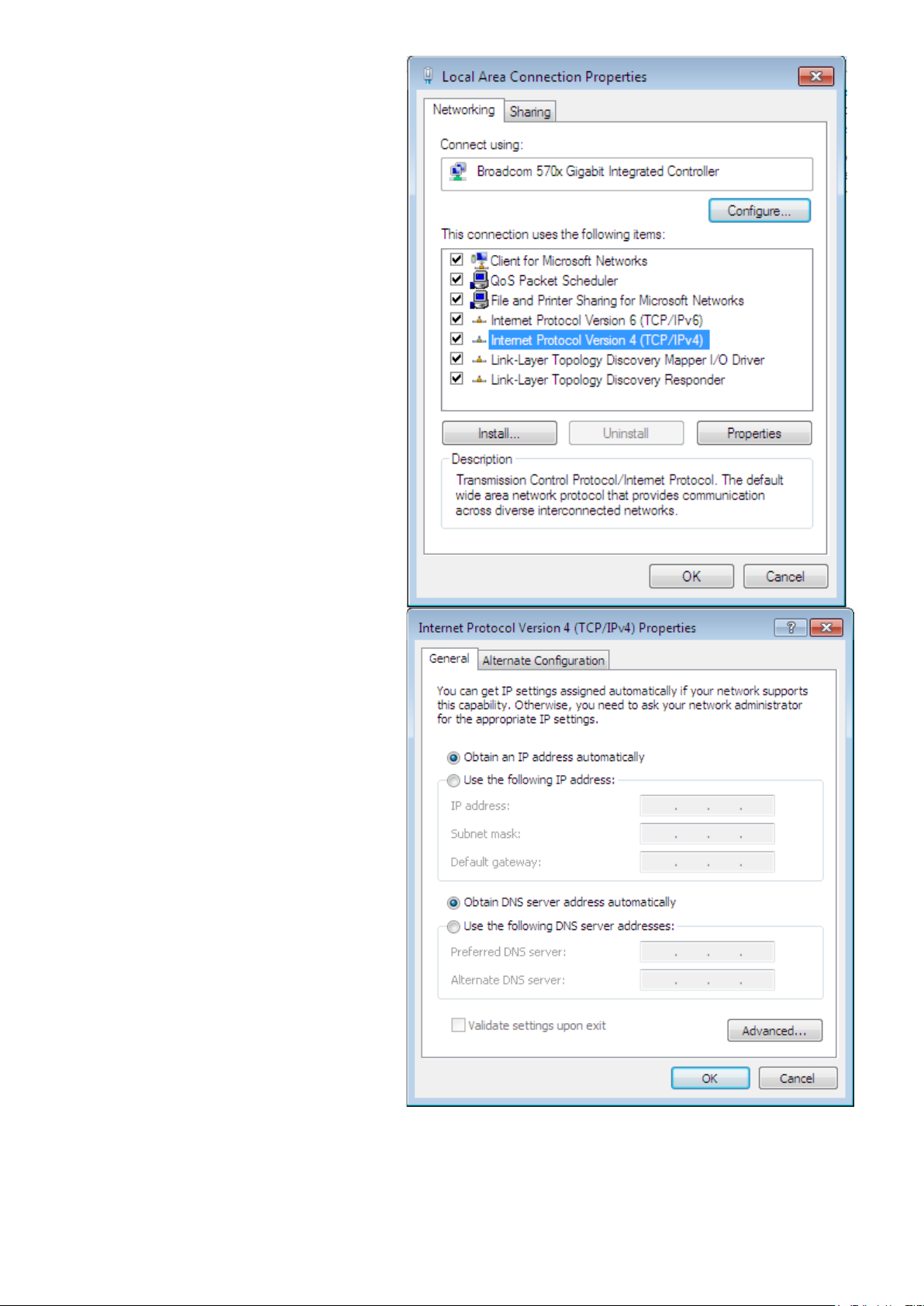
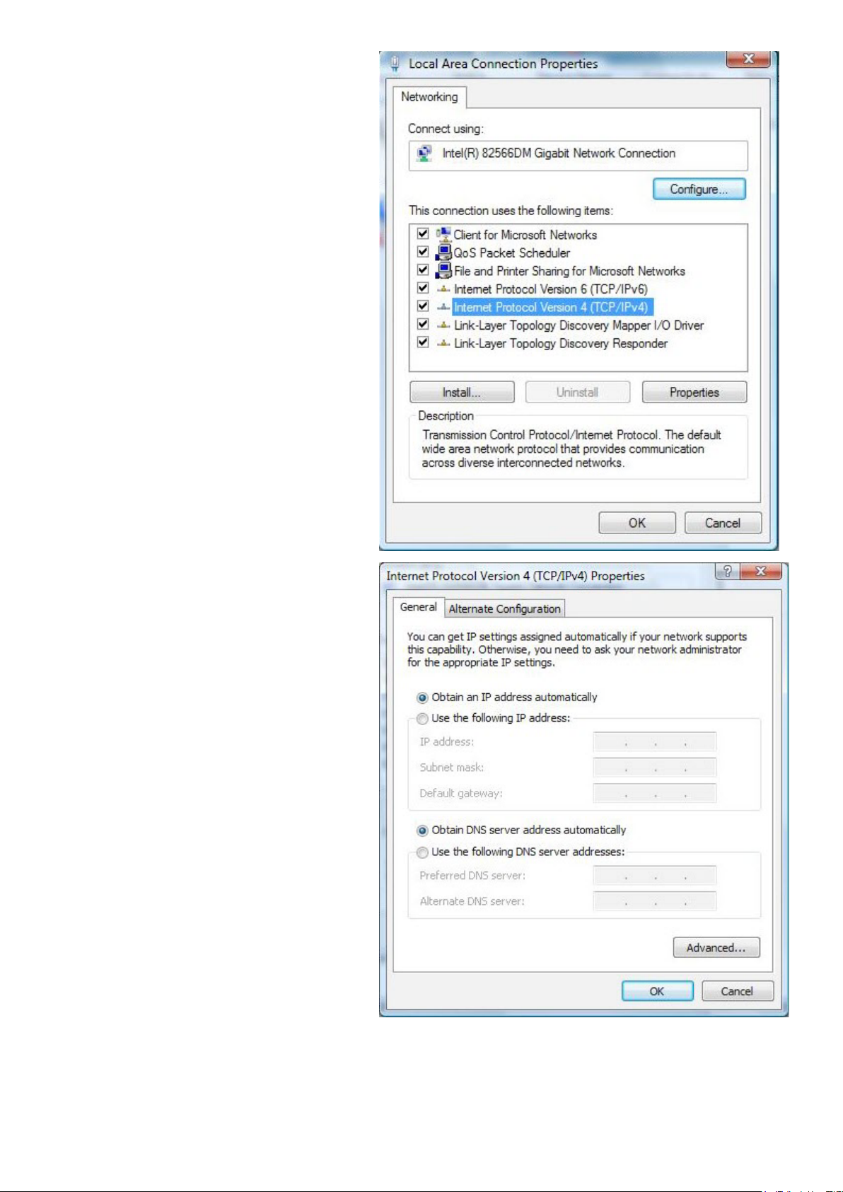
5. Select Internet Protocol Version 4
(TCP/IPv4) then click Properties.
6. In the TCP/IPv4 properties window,
select the Obtain an IP address
automatically and Obtain DNS
Server address automatically radio
buttons. Then click OK to exit the
setting.
7. Click OK again in the Local Area
Connection Properties window to
apply the new conguration.
14
Page 19
Conguring PC in Windows Vista
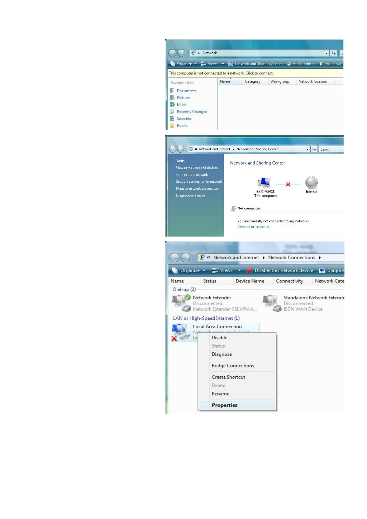
1. Go to Start. Click on Network.
2. Then click on Network and Sharing
Center at the top bar.
3. When the Network and Sharing
Center window pops up, select
and click on Manage network
connections on the left window
column.
4. Select the Local Area Connection,
and right click the icon to select
Properties.
15
Page 20
5. Select Internet Protocol Version 4
(TCP/IPv4) then click Properties.
6. In the TCP/IPv4 properties window,
select the Obtain an IP address
automatically and Obtain DNS
Server address automatically radio
buttons. Then click OK to exit the
setting.
7. Click OK again in the Local Area
Connection Properties window to
apply the new conguration.
16
Page 21
Conguring PC in Windows XP
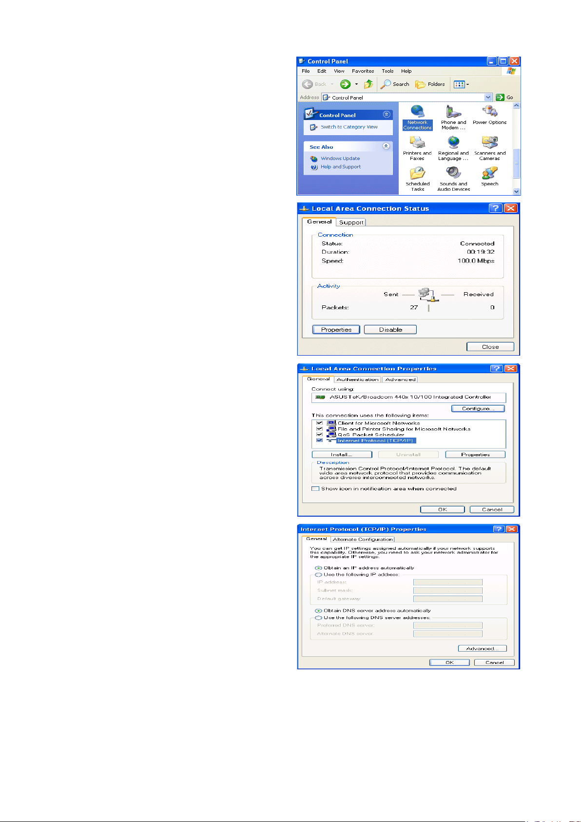
1. Go to Start > Control Panel (in Classic
View). In the Control Panel, double-click
on Network Connections
2. Double-click Local Area Connection.
3. In the Local Area Connection Status
window, click Properties.
4. Select Internet Protocol (TCP/IP) and
click Properties.
5. Select the Obtain an IP address automatically and the Obtain DNS server
address automatically radio buttons.
6. Click OK to nish the conguration.
17
Page 22
Conguring PC in Windows 2000
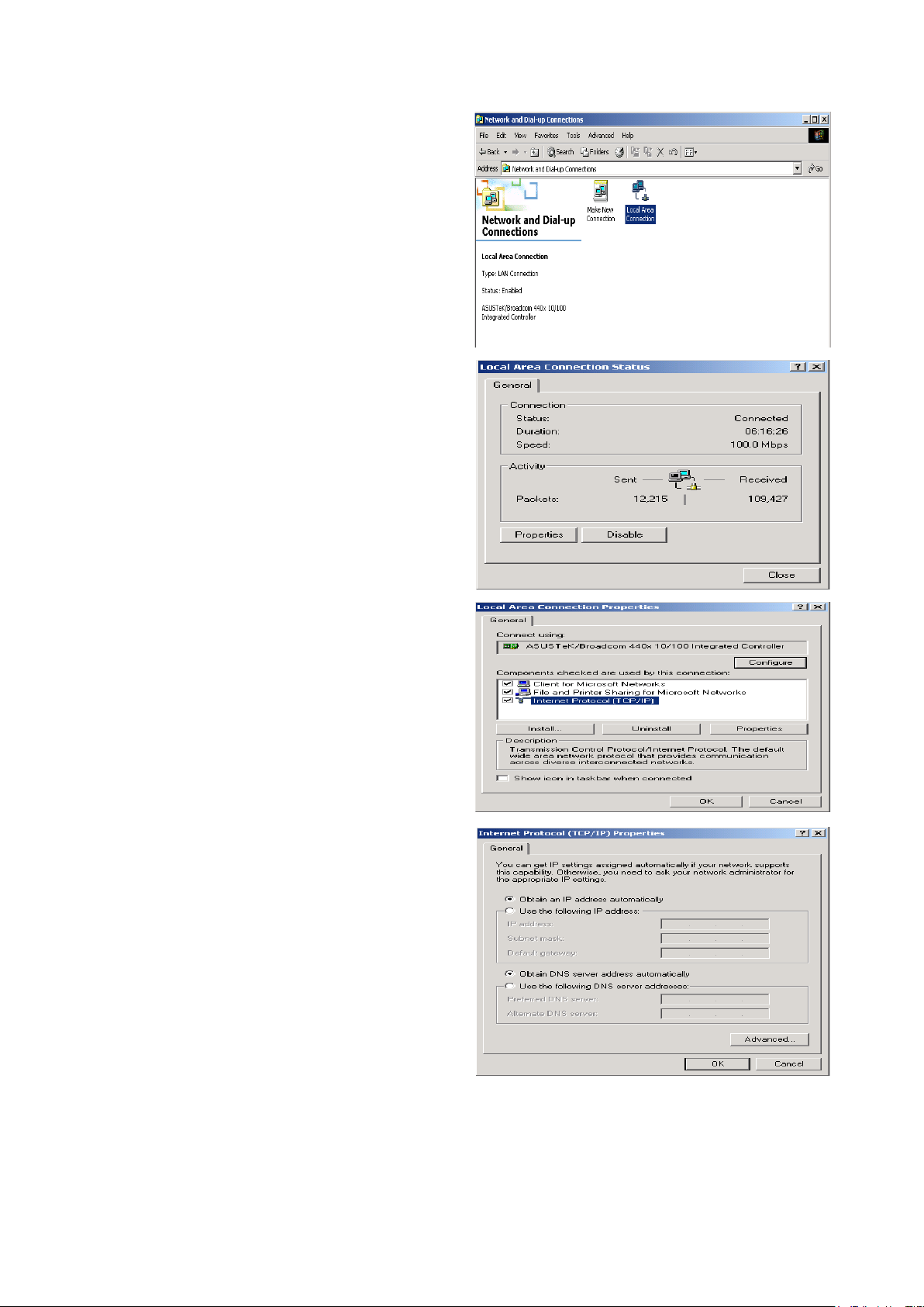
1. Go to Start > Settings > Control Panel.
In the Control Panel, double-click on
Network and Dial-up Connections.
2. Double-click Local Area Connection.
3. In the Local Area Connection Status
window click Properties.
4. Select Internet Protocol (TCP/IP) and
click Properties.
5. Select the Obtain an IP address
automatically and the Obtain DNS server
address automatically radio buttons.
6. Click OK to nish the conguration.
18
Page 23

Conguring PC in Windows 95/98/Me
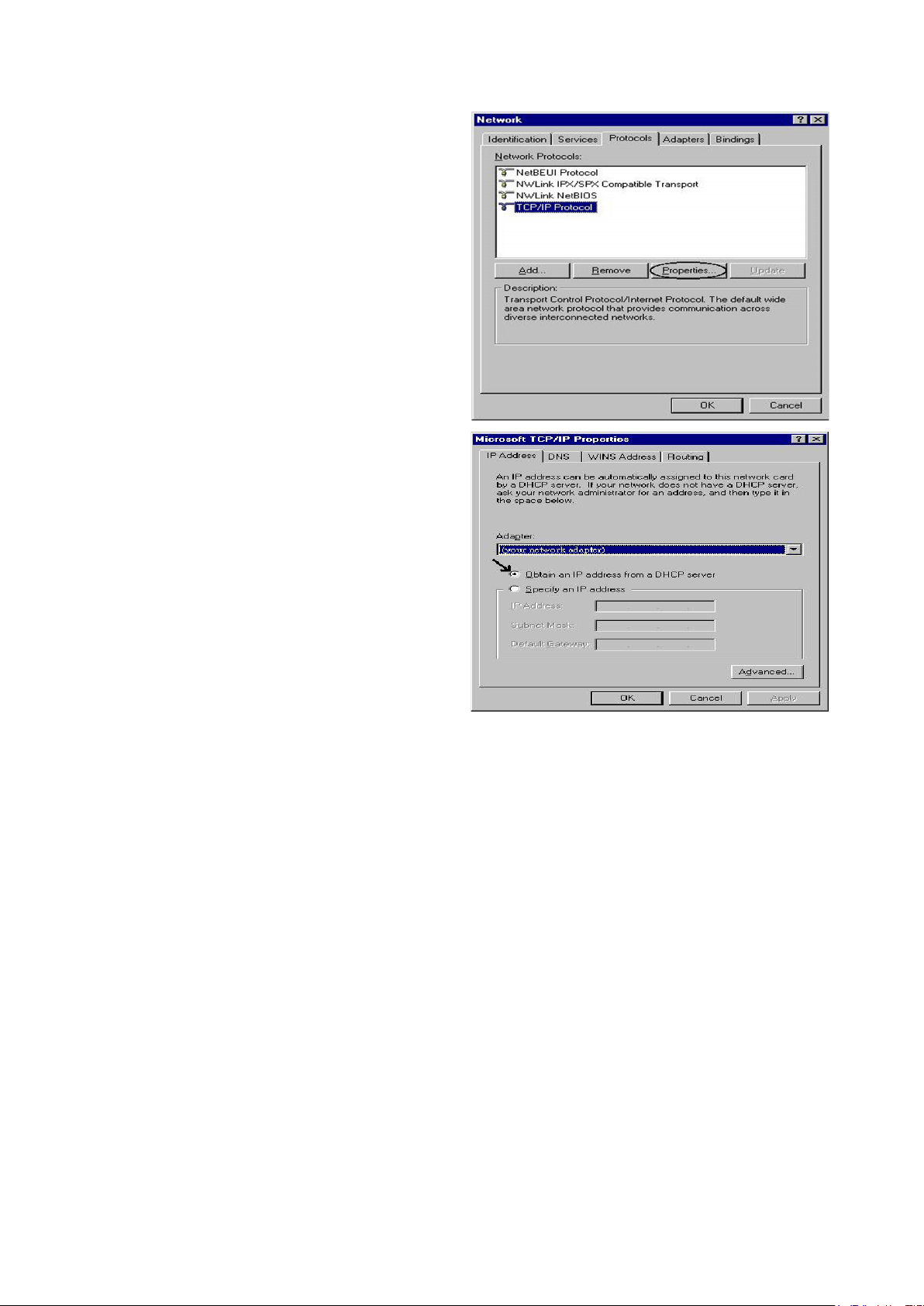
1. Go to Start > Settings > Control Panel.
In the Control Panel, double-click on
Network and choose the Conguration
tab.
2. Select TCP/IP > NE2000 Compatible,
or the name of your Network Interface
Card (NIC) in your PC.
3. Select the Obtain an IP address automatically radio button.
4. Then select the DNS Congurationtab.
5. Select the Disable DNS radio button
and click OK to nish the conguration.
19
Page 24
Conguring PC in Windows NT4.0
1. Go to Start > Settings > Control Panel.
In the Control Panel, double-click on
Network and choose the Protocols tab.
2. Select TCP/IP Protocol and click Properties.
3. Select the Obtain an IP address from
a DHCP server radio button and click
OK.
20
Page 25
Factory Default Settings
Before conguring your router, you need to know the following default settings.
Web Interface (Username and Password)
Three user levels are provided by this router, thus Administrator, Basic and Advanced respectively.
You can turn to User Management to change the corresponding passwords and get more.
Administrator
Username: admin
Password: admin
Basic(local)
Username: user
Password: user
Advanced (for remote login)
Username: support
Password: support
Device LAN IP settings
IP Address: 192.168.1.254
Subnet Mask: 255.255.255.0
ISP setting in WAN site
PPPoE
DHCP server
DHCP server is enabled.
Start IP Address: 192.168.1.100
IP pool counts: 100
21
Page 26

LAN and WAN Port Addresses
The parameters of LAN and WAN ports are pre-set in the factory. The default values are shown in
the tale.
LAN Port WAN Port
IP address 192.168.1.254
Subnet Mask 255.255.255.0
DHCP server function Enabled
IP addresses for
distribution to PCs
100 IP addresses continuing
from 192.168.1.100 through
192.168.1.199
The PPPoE function is
enabled to automatically get
the WAN port conguration
from the ISP.
Information from your ISP
Before conguring this device, you have to check with your ISP (Internet Service Provider) to nd
out what kind of service is provided such as DHCP (Obtain an IP Address Automatically, Static IP
(Fixed IP Address) or PPPoE.
Gather the information as illustrated in the following table and keep it for reference.
VPI/VCI, VC / LLC-based multiplexing, Username, Password, Service
PPPoE(RFC2516)
PPPoA(RFC2364)
MPoA(RFC1483/
RFC2684)
IPoA(RFC1577)
Name, and Domain Name System (DNS) IP address (it can be
automatically assigned by your ISP when you connect or be set manually).
VPI/VCI, VC / LLC-based multiplexing, Username, Password and Domain
Name System (DNS) IP address (it can be automatically assigned by your
ISP when you connect or be set manually).
VPI/VCI, VC / LLC-based multiplexing, IP address, Subnet mask, Gateway
address, and Domain Name System (DNS) IP address (it is a xed IP
address).
VPI/VCI, VC / LLC-based multiplexing, IP address, Subnet mask, Gateway
address, and Domain Name System (DNS) IP address (it is a xed IP
address).
Pure Bridge VPI/VCI, VC / LLC-based multiplexing to use Bridged Mode.
22
Page 27
Chapter 4: Conguration
To easily congure this device for internet access, you must have IE 5.0 / Netscape 4.5 or above
installed on your computer. There are basically 2 ways to congure your router before you are able
to connect to the internet: Easy Sign-On & Web Interface. Conguration of each method will be
discussed in detail in the following sections.
Easy Sign-On (EZSO)
This special feature makes it easier for you to congure your router so that you can connect to the
internet in a matter of seconds without having to logon to the router GUI for any detail conguration.
This conguration method is usually auto initiated if user is to connect to the internet via Billion's
router for the rst time.
After setting up the router with all the appropriate cables plugged-in, open up your IE browser,
the EZSO WEB GUI will automatically pop up and request that you enter some basic information
that you have obtained from your ISP. By following the instructions given carefully and through the
information you provide, the router will be congured in no time and you will nd yourself surng the
internet sooner than you realize.
Follow the Easy Sign-On conguration wizard to complete the basic network conguration.
1. Connect your router with all the appropriate cables. Then, load your IE / netscape browser.
2. When the EZSO conguration wizard pops up, select the connect mode which you want to set
up and then click continue.
23
Page 28
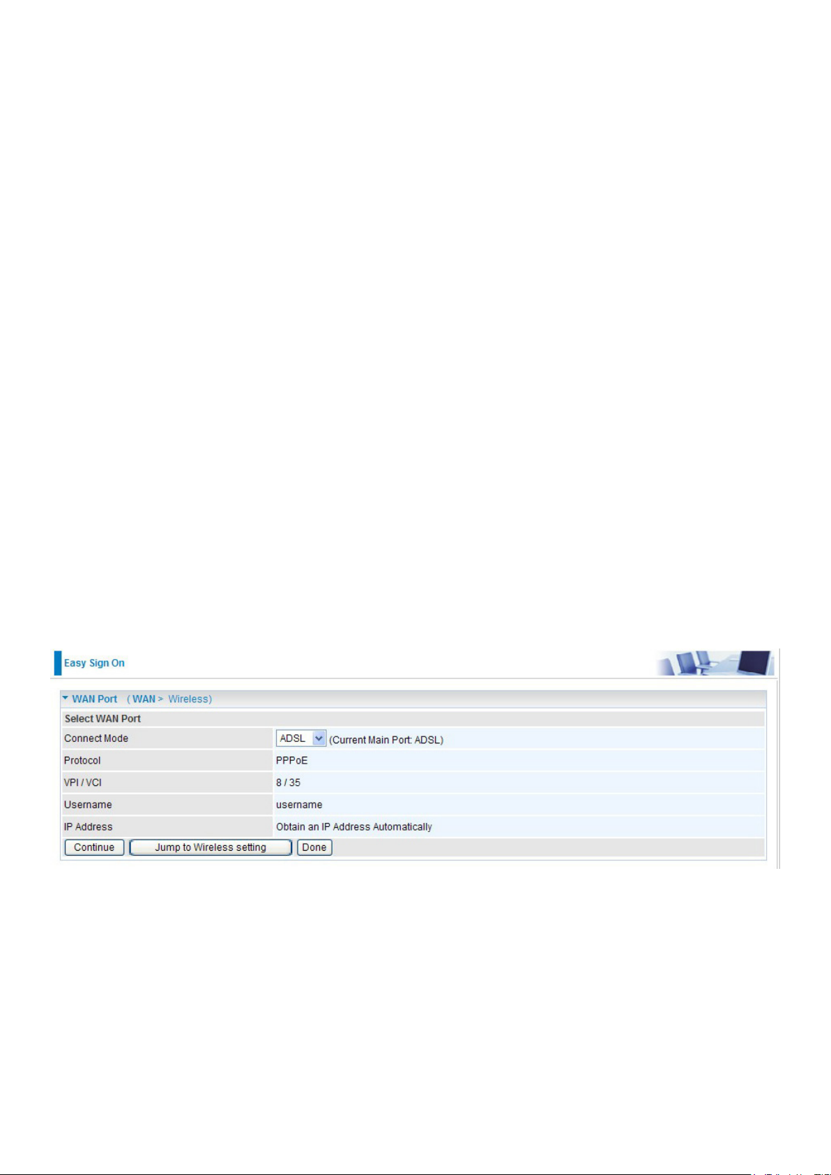
3. Please enter all the information in the blanks provided and then click continue.
4. The device will reboot and then load the new conguration.
5. If all information provided is valid and the device successfully connects to WAN, a dialog box
will appear to signify the completion of the WAN port setup. At this point you can either click
Done to nish the EZSO conguration or you can click Next to wireless to proceed to the wireless conguration if you have.
6. However, if any error occurs during device conguration that results in WAN connection failure,
the system will prompt that the setup has failed.
24
Page 29
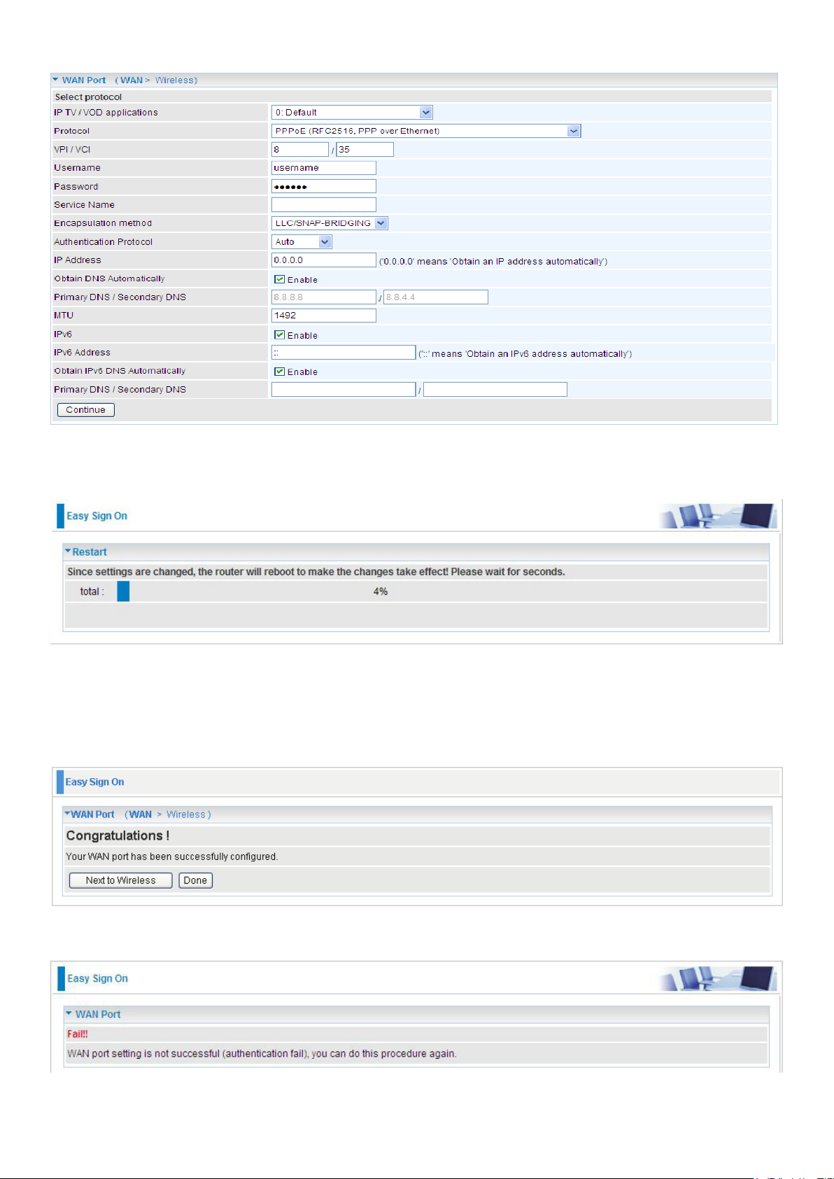
7. Select Enable and enter the necessary information in the blanks provided for the Wireless LAN
setting (wireless setting is only available for BiPAC 7800N) if you would like to use this feature
and then click Continue.
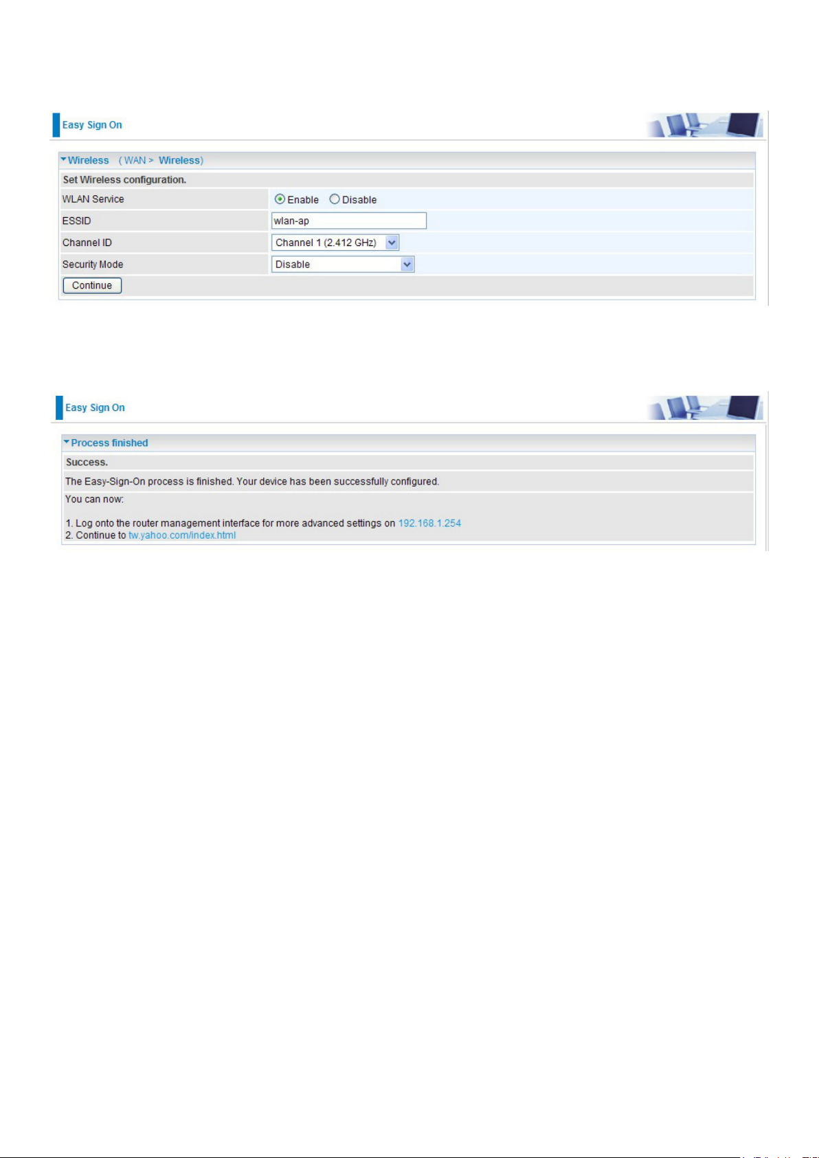
8. The system will save your new conguration and complete the setup. You can test the con-
nection by clicking on the URL link provided. If the setup is successful you will be redirected to
website.
25
Page 30
Conguration via Web Interface
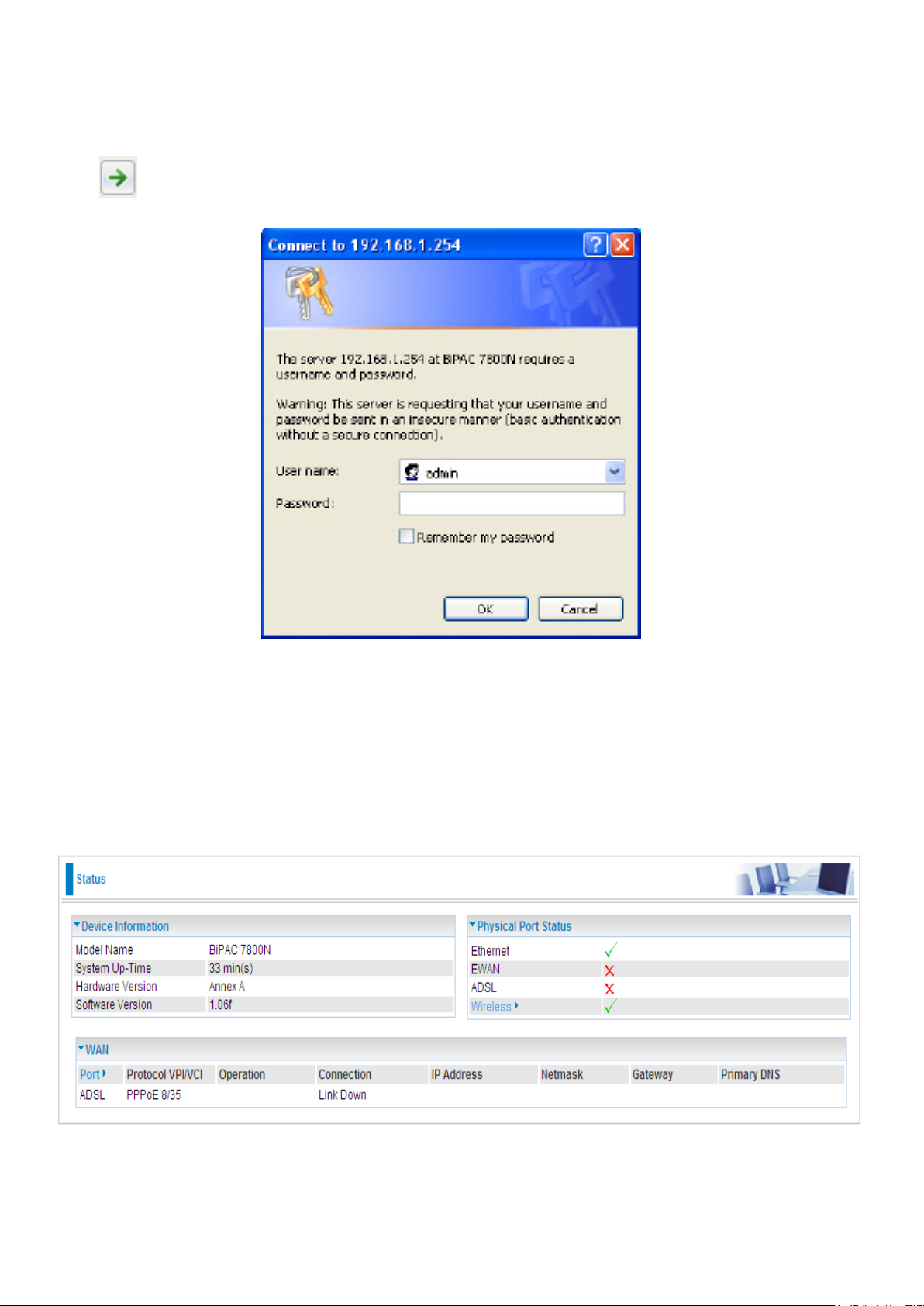
Open your web browser, enter the IP address of your router, which by default is 192.168.1.254, and
click or press ‘Enter’ key on the keyboard, a login prompt window will appear. The default
username and password are “admin” and “admin” respectively.
Congratulations! You are now successfully logged in to the Firewall Router!
If the authentication succeeds, the homepage Status will appear on the screen.
26
Page 31

Quick Start
ADSL Mode
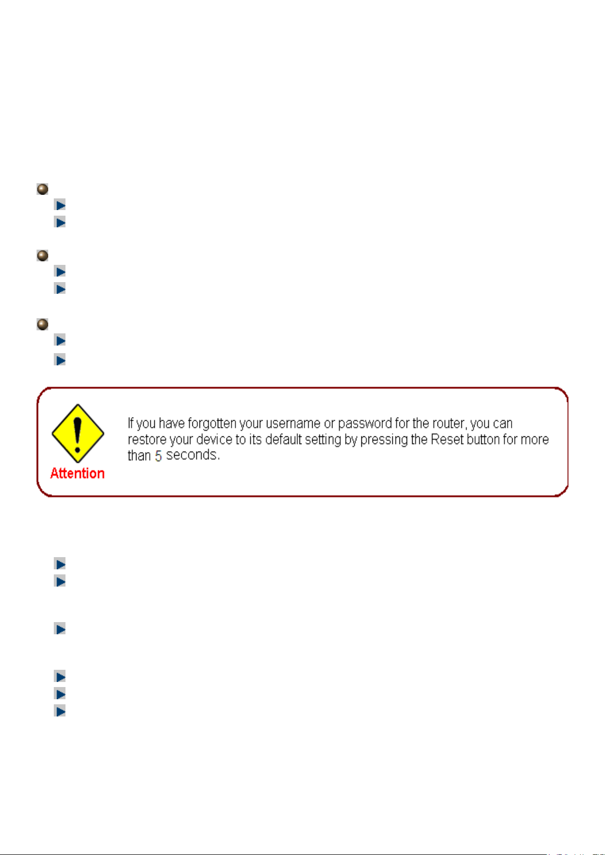
Step 1: Select WAN port connect mode from the connect mode drop down menu. There are two
types of connect mode to choose from: ADSL or EWAN. Here select ADSL and click Continue. If
you only want to congure Wireless, press Jump to Wireless setting.
Step 2: When ADSL line is not ready, the screen1 below will appear to remind you. Then you should
connect the ADSL line. While ADSL line is ready, the screen 2 below will appear to let you go
on.Here you can select Auto or Manually. Select Auto will go to step 3, and select Manually will go
to step 4.
Screen1
Screen 2
27
Page 32

Step3: Wait while the DSL is scanning, when the scanning is OK, the scanning result will appear,
see screen 3, and then it will quickly goes to step 4. Or you can Abort to manually setting to step
4.
Screen 3
Step 4: There are 5 types of connection protocols available under ADSL connect mode .Each type
of connection mode is described in the following sections of ADSL Connect mode. Select the
needed protocol and enter the needed information from your ISP.
28
Page 33

Step 5: The device will reboot and then load the new conguration.
Step 6: WAN port conguration is success. And if you want contiune conguring wireless, press
Next to Wireless button to go on.
Step 7: Enter the ESSID, select the Channel ID and the Security Mode, click Continue to go on. For
detail, please turn to WLAN in this manual for help.
29
Page 34

Step 8: Quick Star is nished.
You can go to the Status and view the basic information.
30
Page 35

ADSL Connect Mode
For ADSL connect mode there are 5 types of connection protocols: PPPoE, PPPoA, IPoA, MPoA
and Pure Bridge.
PPPoE
IP TV / VOD applications: The predened WAN settings for users. Users can adopt the appropriate
one base on need.
VPI/VCI: Enter the information provided by your ISP.
Username: Enter the username provided by your ISP. You can input up to 256 alphanumeric
characters (case sensitive).
Password: Enter the password provided by your ISP. You can input up to 32 alphanumeric characters
(case sensitive).
Service Name: This item is for identication purposes. If it is required, your ISP will provide you the
necessary information. Maximum input is 32 alphanumeric characters.
Encapsulation method: Select the encapsulation format. Select the one provided by your ISP.
Authentication method: Default is Auto. Please consult your ISP on whether to use Chap, Pap or
MSCHAP.
IP Address: Your WAN IP address. Leave the IP address as 0.0.0.0 to enable the device to
automatically obtain an IP address from your ISP.
Obtain DNS Automatically: Click to activate DNS and to enable the system to automatically detect
DNS.
Primary DNS / Secondary DNS: Enter the IP addresses of the DNS servers. The DNS servers are
passed to the DHCP clients along with the IP address and the netmask.
31
Page 36

MTU: Maximum Transmission Unit. The size of the largest datagram (excluding media-specic
headers) that IP will attempt to send through the interface.
IPv6: check to enable IPv6 service. If enabled, please set the IPv6 Address, Ipv6 DNS, similar as
IPv4.
IPv6 Address: type the IPv6 address from your ISP, or get it automatically. ”::” means to obtain IPv6
address automatically.
Obtain IPv6 DNS: check Automatic to obtain DNS automatically. If not, please type the exact ones
in the Primary and secondary elds.
32
Page 37

PPPoA
IP TV / VOD applications:
The predened WAN settings for users. Users can adopt the appropriate
one base on need.
VPI/VCI:
Username:
characters (case sensitive).
Password:
(case sensitive).
Encapsulation method:
Authentication method:
MSCHAP.
IP Address:
automatically obtain an IP address from your ISP.
Obtain DNS automatically:
DNS.
Primary DNS / Secondary DNS:
passed to the DHCP clients along with the IP address and the netmask.
Enter the information provided by your ISP.
Enter the username provided by your ISP. You can input up to
Enter the password provided by your ISP. You can input up to
Select the encapsulation format. Select the one provided by your ISP.
Default
Your WAN IP address. Leave the IP address as 0.0.0.0 to enable the device to
is Auto. Please consult your ISP on whether to use Chap, Pap or
Click to activate DNS and to enable the system to automatically detect
Enter the IP addresses of the DNS servers. The DNS servers are
256
alphanumeric
32
alphanumeric characters
MTU:
headers) that IP will attempt to send through the interface.
Maximum Transmission Unit.
The size of the largest datagram (excluding media-specic
33
Page 38

IPv6: check to enable IPv6 service. If enabled, please set the IPv6 Address, Ipv6 DNS, similar as
IPv4.
IPv6 Address: type the IPv6 address from your ISP, or get it automatically. ”::” means to obtain IPv6
address automatically.
Obtain IPv6 DNS: check Automatic to obtain DNS automatically. If not, please type the exact ones
in the Primary and secondary elds.
34
Page 39

IPoA Connection
IP TV / VOD applications: The predened WAN settings for users. Users can adopt the appropriate
one base on need.
VPI/VCI: Enter the VPI and VCI information provided by your ISP.
Encapsulation method: Select the encapsulation format. Select the one provided by your ISP.
IP Address: IPOA WAN IP address can only set xed IP address.
Netmask: User can change it to others such as 255.255.255.128. Type the netmask assigned to
you by your ISP (if given).
Gateway: Enter the IP address of the default gateway.
Obtain DNS automatically: Click to activate DNS and to enable the system to automatically detect
DNS.
Primary DNS / Secondary DNS: Enter the IP addresses of the DNS servers. The DNS servers are
passed to the DHCP clients along with the IP address and the netmask.
35
Page 40

MPoA Connection
IP TV / VOD applications: The predened WAN settings for users. Users can adopt the appropriate
one base on need.
VPI/VCI: Enter the VPI and VCI information provided by your ISP.
Encapsulation method: Select the encapsulation format. Select the one provided by your ISP.
IP Address: Your WAN IP address. If the IP is set to 0.0.0.0 (auto IP detect), both netmask and
gateway may be left blank.
Netmask: User can change it to others such as 255.255.255.128. Type the netmask assigned to
you by your ISP (if given).
Gateway: Enter the IP address of the default gateway.
Obtain DNS automatically: Click to activate DNS and to enable the system to automatically detect
DNS.
Primary DNS / Secondary DNS: Enter the IP addresses of the DNS servers. The DNS servers are
passed to the DHCP clients along with the IP address and the netmask.
IPv6: check to enable IPv6 service. If enabled, please set the IPv6 Address, Ipv6 DNS, similar as
IPv4.
36
Page 41

IP/Prex Length: please type the IP and the prex length for the IPv6 address from your ISP.
IPv6 Gateway: Type the gateway to which the WAN packets are forwarded.
Obtain IPv6 DNS: check Automatic to obtain DNS automatically. If not, please type the concrete
ones in the Primary and Secondary elds.
Pure Bridge Connection
IP TV / VOD applications: The predened WAN settings for users. Users can adopt the appropriate
one base on need.
VPI/VCI: Enter the VPI and VCI information provided by your ISP.
Encap. method: Select the encapsulation format. Select the one provided by your ISP.
Click Apply to conrm the settings.
Page 42

EWAN Mode
Step 1: Select WAN port connect mode from the connect mode drop down menu. There are two
types of connect mode to choose from: ADSL or EWAN. Here select EWAN and click Continue. If
you only want to congure Wireless, press Jump to Wireless setting.
Step 2: there are four availabe protocols. Each protocol is described in the following sections
of EWAN Connect mode. Select the protocol. You can enable or disable VLAN Mux feature, if
enabled, you should enter the 802.1Q VLAN ID. For VLAN MUX setting, please refer to VLAN MUX
Setting for help. Click Continue to go on.
Step 3: The device will reboot and then load the new conguration.
38
Page 43

Step 4: WAN port conguration is sucess, now Next to Wireless.
Step 5: Enter the ESSID, select the Channel ID and the Security Mode. For security information,
please turn to WLAN section in this manual for help.
Step 6: Quick Start is nished.
39
Page 44

EWAN Connect Mode
PPPoE connection
Username: Enter the username provided by your ISP. You can input up to 256 alphanumeric
characters (case sensitive).
Password: Enter the password provided by your ISP. You can input up to 32 alphanumeric characters
(case sensitive).
Service Name: This item is for identication purposes. If it is required, your ISP will provide you the
necessary information. Maximum input is 32 alphanumeric characters.
Authentication Protocol: Default is Auto. Please consult your ISP on whether to use Chap, Pap or
MSCHAP.
IP Address: Enter your xed IP address.
Obtain DNS automatically: Click to activate DNS and to enable the system to automatically detect
DNS.
Primary DNS / Secondary DNS: Enter the IP addresses of the DNS servers. The DNS servers are
passed to the DHCP clients along with the IP address and the netmask.
MTU: Maximum Transmission Unit. The size of the largest datagram (excluding media-specic
40
Page 45

headers) that IP will attempt to send through the interface.
VLAN Mux: check whether to enable VLAN Mux function.
802.1Q VLAN ID: It is a parameter to specify the VLAN which the frame belongs. Enter the VLAN
ID identication, tagged: 2-4095.
IPv6: check to enable IPv6 service. Enter IPv6 Gateway address and set IPv6 DNS as same in IPv4
mode.
IPv6 Address: type the IPv6 address from your ISP, or get it automatically. ” ::” means to obtain IPv6
address automatically.
Obtain IPv6 DNS: check Automatic to obtain DNS automatically. If not, please type the concrete
ones in the Primary and Secondary elds.
Obtain an IP Address Automatically
Select this protocol enables the device to automatically obtain IP address.
VLAN Mux: check whether to enable VLAN Mux function.
802.1Q VLAN ID: It is a parameter to specify the VLAN which the frame belongs. Enter the VLAN
ID identication, tagged: 2-4095.
IPv6: Check to enble the function
IPv6 Gateway: Enter the IP address of the default IPv6 gateway.
41
Page 46

Fixed IP Address
IP Address: Enter your xed IP address.
Netmask: User can change it to others such as 255.255.255.128. Type the netmask assigned to
you by your ISP (if given).
Gateway: Enter the IP address of the default gateway.
Obtain DNS automatically: Click to activate DNS and to enable the system to automatically
detect DNS.
Primary DNS / Secondary DNS: Enter the IP addresses of the DNS servers. The DNS servers
are passed to the DHCP clients along with the IP address and the netmask.
VLAN Mux: check whether to enable VLAN Mux function.
802.1Q VLAN ID: It is a parameter to specify the VLAN which the frame belongs. Enter the VLAN
ID identication, tagged: 2-4095.
IPv6: Check to enble the function.
IP/Prex Length: Enter IP Address and Prex length.
IPv6 Gateway: Enter the IP address of the default IPv6 gateway.
Obtain IPv6 DNS: Click to activate DNS and to enable the system to automatically detect DNS.
Primary DNS / Secondary DNS: Enter the IP addresses of the DNS servers. The DNS servers are
passed to the DHCP clients along with the IP address and the netmask.
42
Page 47

Pure Bridge
VLAN Mux: check whether to enable VLAN Mux function.
802.1Q VLAN ID: It is a parameter to specify the VLAN which the frame belongs. Enter the VLAN
ID identication, tagged: 2-4095.
43
Page 48

Basic Conguration Mode
Status
Device Information
Model Name: Provide a name for the router for identication purposes.
System Up-Time: Record system up-time.
Hardware Version: Device version.
Software Version: Firmware version.
Port Status
Port Status: User can look up to see if they are connected to Ethernet, EWAN, ADSL and Wireless.
WAN
Port: Name of the WAN connection.
Protocol VPI/VCI: Virtual Path Identier and Virtual Channel Identier.
Operation: Current status in WAN interface.
Connection: Current connection time.
IP Address: WAN port IP address.
Netmask: WAN port IP subnet mask.
Gateway: IP address of the default gateway.
Primary DNS: IP address of the primary DNS server.
44
Page 49

WAN – Main Port (ADSL)
A WAN (Wide Area Network) is an outside connection to another network or the Internet.
PPPoE Connection (ADSL)
PPPoE (PPP over Ethernet) provides access control in a manner similar to dial-up services using
PPP.
IP TV / VOD applications: The predened WAN settings for users. Users can adopt the appropriate
one base on need.
VPI/VCI: Enter the information provided by your ISP.
Username: Enter the username provided by your ISP. You can input up to 256 alphanumeric
characters (case sensitive).
Password: Enter the password provided by your ISP. You can input up to 32 alphanumeric characters
(case sensitive).
Service Name: This item is for identication purposes. If it is required, your ISP will provide you the
necessary information. Maximum input is 32 alphanumeric characters.
Encap. method: Select the encapsulation format. Select the one provided by your ISP.
45
Page 50

Auth. Protocol: Default is Auto. Please consult your ISP on whether to use Chap, Pap or MSCHAP.
IP Address(0.0.0.0:Auto): Your WAN IP address. Leave this at 0.0.0.0 to obtain automatically an
IP address from your ISP.
Obtain DNS automatically: Click to activate DNS and to enable the system to automatically detect
DNS.
Primary DNS / Secondary DNS: Enter the IP addresses of the DNS servers. The DNS servers are
passed to the DHCP clients along with the IP address and the netmask.
MTU: Maximum Transmission Unit. The size of the largest datagram (excluding media-specic
headers) that IP will attempt to send through the interface.
IPv6: check to enable IPv6 service. If enabled, please set the IPv6 Address, Ipv6 DNS, similar as
IPv4.
IPv6 Address: type the IPv6 address from your ISP, or get it automatically. ”::” means to obtain IPv6
address automatically.
Obtain IPv6 DNS: check Automatic to obtain DNS automatically. If not, please type the exact ones
in the Primary and secondary elds.
Click Apply to conrm the settings.
46
Page 51

PPPoA Connection (ADSL)
PPPoA stands for Point to Point Protocol over ATM Adaptation Layer 5 (AAL5). It provides access
control and billing functionality in a manner similar to dial-up services using PPP.
IP TV / VOD applications: The predened WAN settings for users. Users can adopt the appropriate
one base on need.
VPI/VCI: Enter the information provided by your ISP.
Username: Enter the username provided by your ISP. You can input up to 256 alphanumeric
characters (case sensitive).
Password: Enter the password provided by your ISP. You can input up to 32 alphanumeric characters
(case sensitive).
Encap. method: Select the encapsulation format. Select the one provided by your ISP.
Auth. Protocol: Default is Auto. Please consult your ISP on whether to use Chap, Pap or MSCHAP.
IP Address(0.0.0.0:Auto): Your WAN IP address. Leave the IP address as 0.0.0.0 to enable the
device to automatically obtain an IP address from your ISP.
Obtain DNS automatically: Click to activate DNS and to enable the system to automatically detect
DNS.
47
Page 52

Primary DNS / Secondary DNS: Enter the IP addresses of the DNS servers. The DNS servers are
passed to the DHCP clients along with the IP address and the netmask.
MTU: Maximum Transmission Unit. The size of the largest datagram (excluding media-specic
headers) that IP will attempt to send through the interface.
IPv6: check to enable IPv6 service. If enabled, please set the IPv6 Address, Ipv6 DNS, similar as
IPv4.
IPv6 Address: type the IPv6 address from your ISP, or get it automatically. ”::” means to obtain IPv6
address automatically.
Obtain IPv6 DNS: check Automatic to obtain DNS automatically. If not, please type the exact ones
in the Primary and secondary elds.
Click Apply to conrm the settings.
MPoA Connection (ADSL)
48
Page 53

IP TV / VOD applications: The predened WAN settings for users. Users can adopt the appropriate
one base on need.
VPI/VCI: Enter the VPI and VCI information provided by your ISP.
Encap. method: Select the encapsulation format. Select the one provided by your ISP.
IP Address: Your WAN IP address. If the IP is set to 0.0.0.0 (auto IP detect), both netmask and
gateway may be left blank.
Netmask: User can change it to others such as 255.255.255.128. Type the netmask assigned to
you by your ISP (if given).
Gateway: Enter the IP address of the default gateway.
Obtain DNS automatically: Click to activate DNS and to enable the system to automatically detect
DNS.
Primary DNS / Secondary DNS: Enter the IP addresses of the DNS servers. The DNS servers are
passed to the DHCP clients along with the IP address and the netmask.
IPv6: check to enable IPv6 service. If enabled, please set the IPv6 Address, Ipv6 DNS, similar as
IPv4.
IP/Prex Length: please type the IP and the prex length for the IPv6 address from your ISP.
IPv6 Gateway: Type the gateway to which the WAN packets are forwarded.
Obtain IPv6 DNS: check Automatic to obtain DNS automatically. If not, please type the concrete
ones in the Primary and Secondary elds.
Click Apply to conrm the settings.
49
Page 54

IPoA Connections (ADSL)
IP TV / VOD applications: The predened WAN settings for users. Users can adopt the appropriate
one base on need.
VPI/VCI: Enter the VPI and VCI information provided by your ISP.
Encap. method: Select the encapsulation format. Select the one provided by your ISP.
IP Address: Enter your xed IP address.
Netmask: User can change it to others such as 255.255.255.128. Type the netmask assigned to
you by your ISP (if given).
Gateway: Enter the IP address of the default gateway.
Obtain DNS automatically: Click to activate DNS and to enable the system to automatically detect
DNS.
Primary DNS / Secondary DNS: Enter the IP addresses of the DNS servers. The DNS servers are
passed to the DHCP clients along with the IP address and the netmask.
Click Apply to conrm the settings.
50
Page 55

Pure Bridge Connections (ADSL)
IP TV / VOD applications: The predened WAN settings for users. Users can adopt the appropriate
one base on need.
VPI/VCI: Enter the VPI and VCI information provided by your ISP.
Encap. method: Select the encapsulation format. Select the one provided by your ISP.
Click Apply to conrm the settings.
51
Page 56

WAN – Main Port (EWAN)
Besides using ADSL to get connected to the Internet, EWAN port of BiPAC 7800(N) can be used
as an alternative to connect to Cable Modems, VDSL and ber optic lines. This alternative not only
provides faster connection to the Internet, it also provides users with more exibility to get online.
PPPoE (EWAN)
Username: Enter the username provided by your ISP. You can input up to 256 alphanumeric
characters (case sensitive).
Password: Enter the password provided by your ISP. You can input up to 32 alphanumeric characters
(case sensitive).
Service Name: This item is for identication purposes. If it is required, your ISP will provide you the
necessary information. Maximum input is 32 alphanumeric characters.
Auth. Protocol: Default is Auto. Please consult your ISP on whether to use Chap, Pap or MSCHAP.
IP Address: Enter your xed IP address.
Obtain DNS automatically: Click to activate DNS and to enable the system to automatically detect
DNS.
Primary DNS / Secondary DNS: Enter the IP addresses of the DNS servers. The DNS servers are
passed to the DHCP clients along with the IP address and the netmask.
MTU: Maximum Transmission Unit. The size of the largest datagram (excluding media-specic
headers) that IP will attempt to send through the interface.
52
Page 57

VLAN Mux: check whether to enable VLAN Mux function.
802.1Q VLAN ID: It is a parameter to specify the VLAN which the frame belongs. Enter the VLAN
ID identication, tagged: 2-4095.
IPv6: check to enable IPv6 service. Enter IPv6 Gateway address and set IPv6 DNS as same in IPv4
mode.
IPv6 Address: type the IPv6 address from your ISP, or get it automatically. ” ::” means to obtain IPv6
address automatically.
Obtain IPv6 DNS: check Automatic to obtain DNS automatically. If not, please type the concrete
ones in the Primary and Secondary elds.
Click Apply to conrm the settings.
Obtain IP Address Automatically (EWAN)
Select this protocol enables the device to automatically retrieve IP address.
Obtain DNS automatically: Click to activate DNS and to enable the system to automatically detect
DNS.
Primary DNS / Secondary DNS: Enter the IP addresses of the DNS servers. The DNS servers are
passed to the DHCP clients along with the IP address and the netmask.
VLAN Mux: check whether to enable VLAN Mux function.
802.1Q VLAN ID: It is a parameter to specify the VLAN which the frame belongs. Enter the VLAN
ID identication, tagged: 2-4095.
IPv6: Check to enble the function
IPv6 Gateway: Enter the IP address of the default IPv6 gateway.
53
Page 58

Fixed IP Address (EWAN)
IP Address: Enter your xed IP address.
Netmask: User can change it to others such as 255.255.255.128. Type the netmask assigned to
you by your ISP (if given).
Gateway: Enter the IP address of the default gateway.
Obtain DNS automatically: Click to activate DNS and to enable the system to automatically detect
DNS.
Primary DNS / Secondary DNS: Enter the IP addresses of the DNS servers. The DNS servers are
passed to the DHCP clients along with the IP address and the netmask.
VLAN Mux: check whether to enable VLAN Mux function.
802.1Q VLAN ID: It is a parameter to specify the VLAN which the frame belongs. Enter the VLAN
ID identication, tagged: 2-4095.
IPv6: Check to enble the function.
IP/Prex Length: Enter IP Address and Prex length.
IPv6 Gateway: Enter the IP address of the default IPv6 gateway.
Primary DNS / Secondary DNS: Enter the IP addresses of the DNS servers. The DNS servers are
passed to the DHCP clients along with the IP address and the netmask.
54
Page 59

Pure Bridge (EWAN)
VLAN Mux: check whether to enable VLAN Mux function.
802.1Q VLAN ID: It is a parameter to specify the VLAN which the frame belongs. Enter the VLAN
ID identication, tagged: 2-4095.
Click Apply to conrm the settings.
55
Page 60

WLAN (only for BiPAC 7800N)
WPA / WPA2
Wireless Parameters
WLAN Service: Default setting is set to Enable. If you do not have any wireless, select Disable.
ESSID: The ESSID is the unique name of a wireless access point (AP) used to distinguish one from
another. For security propose, change to a unique ID name which is already built into the router
wireless interface. It is case sensitive and must not exceed 32 characters. Make sure your wireless
clients have exactly the ESSID as the device in order to connect to your network.
Hide ESSID: This function enables the router to become invisible on the network. Thus, any clients
using the wireless setting to search for available or specic router on the network will not be able
to discover the router whose Hide ESSID function is set to enabled. The default setting is disabled.
Regulation Domain: There are seven Regulation Domains for you to choose from, including North
America (N.America), Europe, France, etc. The Channel ID will be different based on this setting.
Channel ID: Select the wireless connection channel ID that you would like to use.
Note: Wireless performance may degrade if the selected channel ID is already being occupied
by other AP(s).
Security Parameters
Security Mode: You can disable or enable with WPA or WEP to protect wireless network. The
default mode of wireless security is Disable.
RADIUS/802.1x: You can disable or enable the RADIUS service.
WPA Shared Key: The key for network authentication. The input format is in character style and key
size should be in the range between 8 and 63 characters.
56
Page 61

Group Key Renewal: The period of renewal time for changing the security key automatically
between wireless client and Access Point (AP). Default value is 3600 seconds.
If you want to enable the RADIUS function, check Enable and then do the following settings.
RADIUS Server IP Address: The IP address of RADIUS authentication server.
RADIUS Server Port: The port number of RADIUS authentication server here. Default value is
1812.
RADIUS Shared Secret: The password of RADIUS authentication server.
Click Apply to conrm the settings.
57
Page 62

WPA/WPA2 Pre-Shared Key
Wireless Parameters
WLAN Service: Default setting is set to Enable. If you do not have any wireless, select Disable.
ESSID: The ESSID is the unique name of a wireless access point (AP) used to distinguish one from
another. For security propose, change to a unique ID name which is already built into the router
wireless interface. It is case sensitive and must not exceed 32 characters. Make sure your wireless
clients have exactly the ESSID as the device in order to connect to your network.
Hide ESSID: This function enables the router to become invisible on the network. Thus, any clients
using the wireless setting to search for available or specic router on the network will not be able
to discover the router whose Hide ESSID function is set to enabled. The default setting is disabled.
Regulation Domain: There are seven Regulation Domains for you to choose from, including North
America (N.America), Europe, France, etc. The Channel ID will be different based on this setting.
Channel ID: Select the wireless connection channel ID that you would like to use.
Note: Wireless performance may degrade if the selected channel ID is already being occupied
by other AP(s).
Security Parameters
Security Mode: You can disable or enable with WPA or WEP to protect wireless network. The
default mode of wireless security is Disable.
WPA Shared Key: The key for network authentication. The input format is in character style and key
size should be in the range between 8 and 63 characters.
Group Key Renewal: The period of renewal time for changing the security key automatically
between wireless client and Access Point (AP). Default value is 3600 seconds.
Click Apply to conrm the settings.
58
Page 63

WEP
Parameters
WLAN Service: Default setting is set to Enable. If you do not have any wireless, select Disable.
ESSID: The ESSID is the unique name of a wireless access point (AP) used to distinguish one from
another. For security propose, change to a unique ID name which is already built into the router
wireless interface. It is case sensitive and must not exceed 32 characters. Make sure your wireless
clients have exactly the ESSID as the device in order to connect to your network.
Hide ESSID: This function enables the router to become invisible on the network. Thus, any clients
using the wireless setting to search for available or specic router on the network will not be able
to discover the router whose Hide ESSID function is set to enabled. The default setting is disabled.
Regulation Domain: There are seven Regulation Domains for you to choose from, including North
America (N.America), Europe, France, etc. The Channel ID will be different based on this setting.
Channel ID: Select the wireless connection channel ID that you would like to use.
Note: Wireless performance may degrade if the selected channel ID is already being occupied
by other AP(s).
59
Page 64

Security Parameters
Security Mode: You can disable or enable with WPA or WEP to protect wireless network. The
default mode of wireless security is Disable.
RADIUS / 802.1x: You can disable or enable the RADIUS service.
WEP Authentication: To prevent an unauthorized wireless station from accessing the data
transmitted over the network, the router offers a secure data encryption, known as WEP. There are
3 options to select from: Open System, Shared key or both.
Default Used WEP Key: Select the encryption key ID; please refer to Key (1~4) below.
Passphrase: This is used to generate WEP keys automatically based upon the input string and a
pre-dened algorithm in WEP64 or WEP128.
Key (1-4): Enter the key to encrypt wireless data. To allow encrypted data transmission, the WEP
Encryption Key values on all wireless stations must be the same as the router. There are four keys
for your selection. The input format can be either HEX style or ASCII format, 10 and 26 HEX codes
or 5 and 13 ASCII codes are required for WEP64 and WEP128 respectively.
If you want to enable the RADIUS function, check Enable and then do the following settings.
RADIUS Server IP Address: The IP address of RADIUS authentication server.
RADIUS Server Port: The port number of RADIUS authentication server here. Default value is
1812.
RADIUS Shared Secret: The password of RADIUS authentication server.
Click Apply to conrm the settings.
60
Page 65

Advanced Conguration Mode
Status
Device Information
Model Name: Displays the model name.
Host Name: Provide a name for the router for identication purposes. Host Name lets you change
the router name.
System Up-Time: Records system up-time.
Current time: Set the current time. See the Time Zone section for more information.
Hardware Version: Device version.
Software Version: Firmware version.
MAC Address: The LAN MAC address.
LAN IPv6 Address: Show the IPv6 Address
Port Status
Port Status: User can look up to see if they are connected to Ethernet, EWAN, ADSL and Wireless.
WAN
Port: Name of the WAN connection.
Protocol VPI/VCI: Virtual Path Identier and Virtual Channel Identier
Operation: The current status in WAN interface.
Connection: The current connection status.
61
Page 66

IP Address: WAN port IP address.
Netmask: WAN port IP subnet mask.Gateway: The IP address of the default gateway.
Primary DNS: The IP address of the primary DNS server.
62
Page 67

ADSL
DSP Firmware Version: DSP code version.
DMT Status: Current DMT Status.
Operational Mode: Display the ADSL state when the connect mode is set to AUTO.
Upstream: Upstream rate.
Downstream: Downstream rate.
SNR Margin (Upstream): This shows the SNR margin for upstream rate.
SNR Margin (Downstream): This shows the SNR margin for downstream rate.
Line Attenuation (Upstream): This is attenuation of signal in upstream.
Line Attenuation (Downstream): This is attenuation of signal in downstream.
63
Page 68

WAN Statistics
Protocol: Service name that is used for connection.
VPI/VCI: It is provided by ISP.
Received: Include received Bytes, Pkts, Errs and Drops.
Transmitted: Include transmitted Bytes, Pkts, Errs and Drops.
64
Page 69

ARP
This table stores mapping information that the device uses to nd the Layer 2 Media Access Control
(MAC) address that corresponds to the Layer 3 IP address of the device via the Address Resolution
Protocol (ARP) feature.
ARP Table
IP Address: Shows the IP Address of the device that the MAC address maps to.
MAC Address: Shows the MAC address that is corresponded to the IP address of the device it is
mapped to.
Interface: The interface name (on the router) that this IP address connects to.
Static ARP: Shows the status of static ARP.
Neighbor Cache Table
IPv6 address: Shows the IPv6 Address of the device that the MAC address maps to.
MAC Address: Shows the MAC address that is corresponded to the IPv6 address of the device it is
mapped to.
Device: here refers to the physical interface, it is a concept to identify Clients from LAN or WAN. For
example, the Clients in LAN, here displays “br0”.
65
Page 70

DHCP
This Table lists the DHCP lease information for all IP addresses assigned by the DHCP server in the
device.
IP Address: This is the IP address that is assigned to the host with this MAC address.
MAC Address: The MAC Address of internal dhcp client host.
Client Host Name: The Host Name of internal dhcp client.
Register Information: Shows the information provided during registration.
66
Page 71

System Log
Display system logs accumulated up to the present time. You can trace its historical information with
this function.
Refresh: Click to update the system log.
Clear: Click to clear the current log from the screen.
67
Page 72

Firewall Log
Firewall Log displays a log that contains information of any unexpected actions that occur to your
rewall settings.
UPnP Portmap
This section lists all the established port-mapping using UPnP (Universal Plug and Play). See the
Advanced section of this manual for more details on UPnP and the router UPnP conguration options.
68
Page 73

PPTP Satus
PPTP Client
Name: the name for your PPTP Client connection.
Enable: Whether the PPTP connection is currently Enable or not.
Connection Type: Whether the Connection type is Remote Access or LAN to LAN.
Status: Displays Not Connected or Connected.
Client IP: Assigned by PPTP server.
PPTP Server
Name: The name you assigned to the particular PPTP entry.
Enable: Whether the PPTP connection is currently Enable or Disable.
Status: Whether the PPTP is Active, Inactive or Disable.
Connection Type: Whether the Connection type is Remote Access or LAN to LAN.
Peer Network: The Remote subnet for LAN to LAN as connection type.
Connect by: The remote address when connected.
Action: Manually drop the tunnel.
69
Page 74

Conguration
When you click this item, the column will expand to display the sub-items that will allow you to further
congure your GPON router.
LAN, WAN, System, Firewall, QoS, Virtual Server, Wake on LAN, Certicate, Time Schedule
and Advanced.
The function of each conguration sub-item is described in the following sections.
70
Page 75

LAN
A Local Area Network (LAN) is a shared communication system network where many computers
are connected. This type of network is area dened and is usually limited to a conned region within
a building or just within the same storey of a building. There are 5 items within the LAN section:
Ethernet, IP Alias, IPv6 Autofconig, Wireless (7800N only), Wireless Security (7800N only),
WPS(7800N only) and DHCP Server.
Ethernet
The router supports more than one Ethernet IP addresses in the LAN, and with distinct LAN subnets
through which you can access the Internet at the same time. Users usually only have one subnet in
their LAN. The default IP address for the router is 192.168.1.254.
IP Address: The default IP on this router.
Netmask: The default subnet mask on this router.
RIP: RIP v1, RIP v2 & RIP v1+v2.
Click Apply to conrm the settings.
IP Alias
This function allows the addition an IP alias to the network interface. This further allows user the
exibility to assign a specic function to use this IP.
IP Address: Enter the IP address to be added to the network.
Netmask: Specify a subnet mask for the IP to be added.
Click Apply to conrm the settings.
71
Page 76

IPv6 Autocong
The IPv6 address composes of two parts, thus, the prex and the interface ID.
There are two ways to dynamically congure IPv6 address on hosts. One is statefull conguration,
for example using DHCPv6 (which resembles its counterpart DHCP in IPv4.) In the stateful
autoconguration model, hosts obtain interface addresses and/or conguration information and
parameters from a DHCPv6 server. The Server maintains a database that keeps track of which
addresses have been assigned to which hosts.
The second way is stateless conguration. Stateless auto-conguration requires no manual
conguration of hosts, minimal (if any) conguration of routers, and no additional servers. The
stateless mechanism allows a host to generate its own addresses using a combination of locally
available information (MAC address) and information (prex) advertised by routers. Routers advertise
prexes that identify the subnet(s) associated with a link, while hosts generate an "interface identier"
that uniquely identies an interface on a subnet. An address is formed by combining the two. When
using stateless conguration, you needn’t congure anything on the client.
Static LAN IPv6 Address Conguration
Interface Address / Prex Length: enter the static LAN IPv6 address, we suggest leave the eld
empty because when setted wrong, it will result in LAN devices not being able to access other IPv6
device through internet. Router will take the same WAN’s prex to LAN side if the eld is empty.
IPv6 LAN application
DHCPv6 Server: check whether to enable DHCPv6 server.
DHCPv6 Server Type: select Stateless or Stateful. When DHCPv6 is enabled, this parameter is
available. Stateless: if selected, the PCs in LAN are congured through RA mode, thus, the PCs in
LAN are congured through RA mode, to obtain the prex message and generate an address using
a combination of locally available information (MAC address) and information (prex) advertised by
routers, but they can obtain such information like DNS from DHCPv6 Server. Stateful: if selected,
the PCs in LAN will be congured like in IPv4 mode, thus obtain addresses and DNS information
72
Page 77

from DHCPv6 server.
Start interface ID: enter the start interface ID. The IPv6 address composed of two parts, thus, the
prex and the interface ID. Interface is like the Host ID compared to IPv4.
End interface ID: enter the end interface ID.
Note: Interface ID does NOT support ZERO COMPRESSION "::". Please enter the complete
information.
For example: Please enter "0:0:0:2" instead of "::2".
Leased Time (hour): the leased time, similar to leased time in DHCPv4, is a time limit assigned to
clients, when expires, the assigned ID will be recycled and reassigned.
Issue Router Advertisement: check whether to enable issue Router Advertisement feature. It is
to send Router Advertisement messages periodically. Router will multicast the v6 Prex information
(similar to v4 network number 192.168.1.0) to all LAN devices if the eld is enabled. We suggest
enabling this eld.
73
Page 78

Wireless (only for BiPAC 7800N)
Parameters
WLAN Service: Default setting is set to Enable. If you do not have any wireless, select Disable.
Time Schedule:
Time Schedule: A self dened time period. You may specify a time schedule for your prioritization
policy.
Here we provide two groups of Time Schedule setting. You can exibly set the time you want the
wireless connection works.
If you select Always On in group1, then the group2 is disabled.
While if you select any other item from the group1 drop-down menu, the group2 will be activated.
Select the timeslot you want, then the wireless will work according to the time of the two time
schedule settings. You can set two timeslots, let wireless works to the two timeslots time you set.
For example: you want your wireless to work at 08:00-18:00 Sunday and 01:00-02:00 Monday, you
74
Page 79

can set like this:
the timesolts
setting
For timeslots setup and detail, refer to Time Schedule section.
Mode: The default setting is 802.11g+n. If you do not know or have both 11g and 11b devices in
your network, then keep the default in mixed mode. From the drop-down manual, you can select
802.11g if you have only 11g card. If you have only 11b card, then select 802.11b. And if you have
11n card, you can select 802.11n.
ESSID: The ESSID is the unique name of a wireless access point (AP) used to distinguish one from
another. For security propose, change to a unique ID name which is already built into the router
wireless interface. It is case sensitive and must not exceed 32 characters. Make sure your wireless
clients have exactly the ESSID as the device in order to connect to your network.
Hide ESSID: This function enables the router to become invisible on the network. Thus, any clients
using the wireless setting to search for available or specic router on the network will not be able
to discover the router whose Hide ESSID function is set to enabled. The default setting is disabled.
Regulation Domain: There are seven Regulation Domains for you to choose from, including North
America (N.America), Europe, France, etc. The Channel ID will be different based on this setting.
Channel ID: Select the wireless connection channel ID that you would like to use.
Note: Wireless performance may degrade if the selected channel ID is already being occupied
by other AP(s).
Channel width: Select either 20 MHz or 20/40 MHz for the channel bandwidth. The higher the
bandwidth the better the performance will be.
TX PowerLevel: It is a function that enhances the wireless transmitting signal strength. User
may adjust this power level from minimum 0 up to maximum 100.
Note: The Power Level maybe different in each access network user premise environment,
choose the most suitable level for your network.
AP MAC Address: It is a unique hardware address of the Access Point.
AP Firmware Version: The Access Point rmware version.
WPS Service: Select Enable if you would like to activate WPS service.
WPS State: This column allows you to set the status of the device wireless setting whether it
has been congured or uncongured. For WPS conguration please refer to the section on Wi-Fi
Network Setup for detail.
WMM: This feature is used to control the prioritization of trafc according to 4 Access categories:
75
Page 80

Voice, Video, Best Effort and Background. Default is set to disable.
Wireless Multicast Forwarding: select Enable to enbale wireless multicasr forwarding feature.
Then you can set the wireless multicast rate to give control to wireless multicast.
Wireless Multicast Rate: species the rate at which multicast packets are transmitted by the
access point on your wireless network. Specifying a high multicast rate may improve performance
of multicast features.
Wireless Distribution System (WDS)
It is a wireless access point mode that enables wireless link and communication with other access
points. It is easy to install simply by dening the peer’s MAC address of the connected AP. WDS
takes advantages of the cost saving and flexibility which no extra wireless client device is required to
bridge between two access points and extending an existing wired or wireless infrastructure network
to create a larger network. It can connect up to 4 wireless APs for extending cover range at the same
time.
In addition, WDS also enhances its link connection security mode. Key encryption and channel must
be the same for both access points.
WDS Service: The default setting is Disabled. Check Enable radio button to activate this
function.
1. Peer WDS MAC Address: It is the associated AP’s MAC Address. It is important that your
peer’s AP must include your MAC address in order to acknowledge and communicate with
each other.
2. Peer WDS MAC Address: It is the second associated AP’s MAC Address.
3. Peer WDS MAC Address: It is the third associated AP’s MAC Address.
4. Peer WDS MAC Address: It is the fourth associated AP’s MAC Address.
Note: For MAC Address, the format can be: xx:xx:xx:xx:xx:xx or xx-xx-xx-xx-xx-xx.
Click Apply to conrm the settings.
You can click Security settings link next to Cancel button to go to Wireless Security screen (see
Wireless Security section).
76
Page 81

Wireless Security (only for BiPAC 7800N)
You can disable or enable wireless security with WPA or WEP for protecting wireless network. The
default mode of wireless security is disabled.
WPA / WPA2
WPA/WPA2 Pre-Shared Key
RADIUS/802.1x:Whether to enable RADIUS function or not (For WPA/WPA2/WEP encryption).
Security Mode: You can choose the type of security mode you want to apply from the drop down
menu.
WPA Algorithms: There are 3 types of the WPA-PSK, WPA2-PSK & WPA/WPA2-PSK. The WPAPSK adapts the TKIP (Temporal Key Integrity Protocol) encrypted algorithms, which incorporates
Message Integrity Code (MIC) to provide protection against hackers. The WPA2-PSK adapts CCMP
(Cipher Block Chaining Message Authentication Code Protocol) of the AES (Advanced Encryption
Security) algorithms.
WPA Shared Key: The key for network authentication. The input format is in character style and key
size should be in the range between 8 and 63 characters.
Group Key Renewal: The period of renewal time for changing the security key automatically
77
Page 82

between wireless client and Access Point (AP). Default value is 3600 seconds.
Click Apply to conrm the settings.
WEP
RADIUS / 802.1x: Whether to enable RADIUS / 802.1x.
WEP Authentication: To prevent unauthorized wireless stations from accessing data transmitted
over the network, the router offers secure data encryption, known as WEP. There are 3 options to
select from: Open System, Shared key or both.
Default Used WEP Key: Select the encryption key ID; please refer to Key (1~4) below.
Passphrase: This is used to generate WEP keys automatically based upon the input string and a
pre-dened algorithm in WEP64 or WEP128.
Key (1-4): Enter the key to encrypt wireless data. To allow encrypted data transmission, the WEP
Encryption Key values on all wireless stations must be the same as the router. There are four keys
for your selection. The input format can be either HEX style or ASCII format, 10 and 26 HEX codes
or 5 and 13 ASCII codes are required for WEP64 and WEP128 respectively.
Click Apply to conrm the settings.
Note: For information about settling Radius/802.1x, please refer to WLAN setup section.
78
Page 83

WPS (only for BiPAC 7800N)
WPS (WiFi Protected Setup) feature is a standard protocol created by Wi-Fi Alliance. This feature
greatly simplies the steps needed to create a Wi-Fi networks for a residential or an ofce setting.
WPS supports 2 types of conguration methods which are commonly known among consumers:
PIN Method & PBC Method.
79
Page 84

Wi-Fi Network Setup (only for BiPAC 7800N)
PIN Method: Congure AP as Registrar
1. Jot down the client’s Pin (eg. 16837546).
2. Enter the Enrollee’s PIN number and then press Start.
3. Launch the wireless client’s WPS utility (eg. Ralink Utility). Set the Cong Mode as Enrollee,
press the WPS button on the top bar, select the AP (eg. wlan-ap) from the WPS AP List column.
Then press the PIN button located on the middle left of the page to run the scan.
80
Page 85

4. The client’s SSID and security setting will now be congured to match the SSID and security
setting of the registrar.
81
Page 86

PIN Method: Congure AP as Enrollee
1. In the WPS conguration page, change the Role to Enrollee. Then press Start.
2. Jot down the WPS PIN (eg. 25879810).
3. Launch the wireless client’s WPS utility (eg. Ralink Utility). Set the Cong Mode as Registrar.
Enter the PIN number in the PIN Code column then choose the correct AP (eg. wlan-ap) from
the WPS AP List section before pressing the PIN button to run the scan.
82
Page 87

4. The router’s (AP’s) SSID and security setting will now be congured to match the SSID and
security setting of the registrar.
83
Page 88

5. Now to make sure that the setup is correctly done, cross check to see if the SSID and the secu-
rity setting of the registrar setting match with the parameters found on both Wireless Conguration and Wireless Security Conguration page.
84
Page 89

85
Page 90

PBC Method:
1. Press the PBC button of the AP.
2. Launch the wireless client’s WPS Utility (eg. Ralink Utility). Set the Cong Mode as Enrollee.
Then press the WPS button and choose the correct AP (eg. wlan-ap) from the WPS AP List
section before pressing the PBC button to run the scan.
86
Page 91

3. When the PBC button is pushed, a wireless communication will be established between your
router and the PC. The client’s SSID and security setting will now be congured to match the
SSID and security setting of the router.
87
Page 92

Wi-Fi Network Setup with Windows Vista WCN:
1. Jot down the AP PIN from the Web (eg. 25879810).
2. Access the Wireless conguration of the web GUI. Enable WPS service, set the WPS State to
Uncongured and then click Apply.
88
Page 93

3.In your Vista operating system, access the Control Panel page, then select Network and Internet
> View Network Computers and Devices. Double click on the BiPAC 7800N icon and enter the
AP PIN in the column provided then press Next.
4. Enter the AP SSID then click Next.
89
Page 94

5. Enter the passphrase then click Next.
6. When you have come to this step, you will have comleted the Wi-Fi network setup using the
built-in WCN feature in Windows Vista.
90
Page 95

DHCP Server
DHCP allows networked devices to obtain information on the parameter of IP, Netmask, Gateway
as well as DNS through the Ethernet Address of the device.
To congure the router’s DHCP Server, select DHCP Server from the DHCP Server Mode drop-
down menu. You can then congure parameters of the DHCP Server including the domain, IP pool
(starting IP address and ending IP address to be allocated to PCs on your network), lease time
for each assigned IP address (the period of time the IP address assigned will be valid), DNS IP
address and the gateway IP address. These details are sent to the DHCP client (i.e. your PC) when
it requests an IP address from the DHCP server. If you check “Use Router as a DNS Server”, the
ADSL Router will perform the domain name lookup, nd the IP address from the outside network
automatically and forward it back to the requesting PC in the LAN (your Local Area Network). Click
Apply to enable this function.
Note:
Option 66: This option is used to identify a TFTP server, User must set TFTP server IP address if
enable option 66.
Click Apply to enable this fuction.
91
Page 96

If you select DHCP Relay from the DHCP Server Mode drop-down menu, you must enter the IP
address of the DHCP server that assigns an IP address to the DHCP client in the LAN. Use this
function only if advised to do so by your network administrator or ISP. Click Apply to enable this
function.
92
Page 97

WAN - Wide Area Network
A WAN (Wide Area Network) is a computer network that covers a broad geographical area (eg.
Internet) that is used to connect LAN and other types of network systems. There are two items within
the WAN section: WAN Interface, WAN Prole and ADSL Mode.
WAN Interface
WAN Interface (ADSL)
Main Port: Select the main port(the WAN connection mode) from the drop-down menu.
Click Apply to conrm the change.
Note:
Current Main Port: indicate the current used main WAN connection mode, default is ADSL.
WAN Interface (EWAN)
Main Port: Select the main port from the drop-down menu.
Click Apply to conrm the change.
93
Page 98

WAN Interface (Dual WAN)
Main Port: Select the main port from the drop-down menu.
WAN1: Choose ADSL or EWAN for WAN1. Click the link to go to WAN Prole page to congure
its parameters.asdffddddd
WAN2: Choose one from the remainninng modes. Click the link to go to WAN Prole page to
congure its parameters.
Connectivity Decision: Enter the value for the times when probing failed to switch backup port.
Failover Probe Cycle: Set the time duration for the Failover Probe Cycle to determine when the
router will switch to the backup connection (backup port) once the main connection (main port)
fails.
Failback Probe Cycle: Set the time duration for the Failback Probe Cycle to determine when the
router will switch back to the main connection (main port) from the backup connection (backup port)
once the main connection communicates again.
Note: The time values entered in Failover Probe Cycle and Failback Probe Cycle elds are set
for
94
Page 99

each probe cycle and decided by Probe Cycle duration multiplied by Connection Decision value(e.g.
60 seconds are multiplied by 12 seconds and 5 consecutive fails).
Detect Rule (either one):
1. Physical Port Error
2. Ping Fail
• No Ping: It will not send any ping packet to determine the connection. It means to
disable the ping fail detection.
• Ping Gateway: It will send ping packet to gateway and wait response from gateway in
every “Probe Cycle”.
• Ping Host: It will send ping packet to specic host and wait response in every “Probe
Cycle”. The host must be an IP address.
Click Apply to conrm the change.
95
Page 100

WAN Prole
WAN Prole (ADSL)
PPPoE Connection (ADSL)
PPPoE (PPP over Ethernet) provides access control in a manner similar to dial-up services using
PPP.
IP TV / VOD applications: The predened WAN settings for users. Users can adopt the appropriate
one base on need.
Description: A given name for the connection.
VPI/VCI: Enter the information provided by your ISP.
Encap. method: Select the encapsulation format. Select the one provided by your ISP.
Username: Enter the username provided by your ISP. You can input up to 256 alphanumeric
characters (case sensitive).
Password: Enter the password provided by your ISP. You can input up to 32 alphanumeric characters
(case sensitive).
Service Name: This item is for identication purposes. If it is required, your ISP will provide you the
necessary information. Maximum input is 32 alphanumeric characters.
NAT: The NAT (Network Address Translation) feature allows multiple users to access the Internet
through a single IP account by sharing a single IP address. If users on your LAN have their own
public IP addresses to access the Internet, NAT function can be disabled.
96
 Loading...