

Page 1

BiPAC 6200NXL
3.75G Wireless-NBroadband
Router
User Manual
Version release: 1.01
Last revised: 2010-2-22
Page 2

Table of Contents
Chapter 1: Introduction........................................................................................................1
Introduction to your Router............................................................................................................1
Features ....................................................................................................................................................2
Chapter 2: Product Overview ..............................................................................................6
Important note for using this router................................................................................................8
Package Contents.........................................................................................................................8
Device Description.........................................................................................................................9
Cabling ........................................................................................................................................11
Chapter 3: Basic Installation..............................................................................................12
Network Configuration.................................................................................................................12
Factory Default Settings..............................................................................................................21
Information from your ISP............................................................................................................22
Configuring with your Web Browser............................................................................................23
Chapter 4: Basic Configuration..........................................................................................24
Status ..........................................................................................................................................25
Quick Start...................................................................................................................................26
WAN............................................................................................................................................27
WLAN..........................................................................................................................................29
Chapter 5: Advanced Configuration...................................................................................32
Status ..........................................................................................................................................33
3G Status.................................................................................................................................................34
ARP Table...............................................................................................................................................35
DHCP Table ............................................................................................................................................35
System Log .............................................................................................................................................36
Firewall Log.............................................................................................................................................36
UPnP Portmap ........................................................................................................................................37
Quick Start...................................................................................................................................38
Configuration...............................................................................................................................43
LAN (Local Area Network).......................................................................................................................43
Page 3

Ethernet...............................................................................................................................................44
IP Alias................................................................................................................................................44
Wireless ..............................................................................................................................................45
Wireless Security ................................................................................................................................47
WPS....................................................................................................................................................50
DHCP Server ......................................................................................................................................62
WAN (Wide Area Network)......................................................................................................................64
WAN Interface(EWAN)........................................................................................................................64
WAN Interface(3G)..............................................................................................................................64
WAN Interface(Dual W AN)..................................................................................................................65
WAN Profile.........................................................................................................................................66
System.....................................................................................................................................................73
Time Zone...........................................................................................................................................73
Firmware Upgrade..............................................................................................................................74
Backup / Restore ................................................................................................................................75
Restart Router.....................................................................................................................................76
User Management ..............................................................................................................................77
Mail Alert .............................................................................................................................................78
USB Server .............................................................................................................................................79
User Management ..............................................................................................................................79
Storage................................................................................................................................................83
Samba Server.....................................................................................................................................86
FTP Server..........................................................................................................................................89
Printer Config......................................................................................................................................90
Webcam..............................................................................................................................................95
Firewall and Access Control....................................................................................................................96
Packet Filter........................................................................................................................................98
MAC Filter.........................................................................................................................................100
Intrusion Detection............................................................................................................................101
QoS (Quality of Service)........................................................................................................................105
Quality of Service Introduction..........................................................................................................105
QoS Setup.........................................................................................................................................105
Virtual Server.........................................................................................................................................109
Port Mapping......................................................................................................................................111
DMZ .................................................................................................................................................. 113
Wake on LAN........................................................................................................................................ 115
Time Schedule ...................................................................................................................................... 116
Advanced...............................................................................................................................................117
Page 4

Static Route....................................................................................................................................... 118
Static ARP......................................................................................................................................... 118
Dynamic DNS.................................................................................................................................... 119
Device Management.........................................................................................................................120
IGMP.................................................................................................................................................127
SNMP Access Control.......................................................................................................................128
Remote Access.................................................................................................................................130
Save Configuration to Flash..................................................................................................................131
Restart...................................................................................................................................................132
Logout....................................................................................................................................................133
Chapter 6: Troubleshooting.............................................................................................134
Appendix: Product Support & Contact.............................................................................136
Page 5

Chapter 1: Introduction
Introduction to your Router
Thank you for purchasing the BiPAC 6200NXL Router. Your new router is an all-in-one unit that
combines a Broadband modem, Ethernet network switch and two USB ports to provide everything you
need to get the machines on your network connected to the Internet over a 3G broadband connection.
The BiP AC 6200NXL supports 3G, PPP over Ethernet, DHCP Client and Fixed IP address to establish
a connection with your ISP.
The perfect solution for connecting a small group of PCs to a high-speed broadband Internet
connection, the BiPAC 6200NXL allows multiple users to have high-speed Internet access
simultaneously.
Your new router also serves as an Internet firewall, protecting your network from access by outside
users. Not only does it provide a natural firewall function with Network Address Translation (NAT), it
also provides rich firewall features to secure your network. All incoming data packets are monitored
and filtered. You can also configure your new router to block internal users from accessing the
Internet.
The BiP AC 6200NXL provides two levels of security support. First, it masks LAN IP addresses making
them invisible to outside users on the Internet, so it is much more difficult for a hacker to target a
machine on your network. Second, it can block and redirect certain ports to limit the services that
outside users can access. To ensure that games and other Internet applications run properly, you can
open specific ports for outside users to access internal services on your network.
The Integrated DHCP (Dynamic Host Control Protocol) client and server services allow multiple users
to get IP addresses automatically when the router boots up. Simply set local machines as a DHCP
client to accept a dynamically assigned IP address from the DHCP server and reboot. Each time a
local machine is powered up; the router recognizes it and assigns an IP address to instantly connect it
to the LAN.
For advanced users, Virtual Service (port mapping) functions allow the product to provide limited
visibility to local machines with specific services for outside users. For instance, a dedicated web
server can be connected to the Internet via the router and then incoming requests for web pages that
are received by the router can be rerouted to your dedicated local web server, even though the server
now has a different IP address.
1
Page 6

Virtual Server can also be used to re-task services to multiple servers. For instance, you can set the
router to allow separated FTP, Web, and Multiplayer game servers to share the same Internet-visible
IP address while still protecting the servers and LAN users from hackers.
Features
3G
3 G-based Internet connections (requires an additional 3G USB modem), with automatic fail-over to
ensure an always-on Internet connection in the event that one of your Internet services fails. The setup
of 3G is simplified by the web browser-based configuration. It is easy for you to access to the Internet
wherever a 3G connection is available, you can even share your Internet connection with others, no
matter whether you’re in a meeting, or taking a cross-country train trip.
802.11n Wireless AP with WPA Support
With integrated 802.1 1n Wireless Access Point in the router , the device offers a quick and easy access
among wired network, wireless network and broadband connection with single device simplicity, and
as a result, mobility to the users. In addition to 300 Mbps 802.11n data rate, it also interoperates
backward with existing 802.11g and 802.11b equipment. The Wi-Fi Protected Access (WPA) and
Wired Equivalent Privacy (WEP) supported features enhance the security level of data protection and
access control via Wireless LAN.
Fast Ethernet Switch
A 3-port 10/100Mbps fast Ethernet switch is built-in with automatic switching between MDI and MDI-X
for 10Base-T and 100Base-TX ports, with auto detection allowing you to use either straight or
cross-over Ethernet cables.
EWAN
BiP AC 6200NXL of fers a W AN port to connect to Cable Modems and fibre optic lines. This alternative,
yet faster method to connect to the internet will provide users more flexibility to get online.
USB Server
BiPAC 6200NXL supports two USB 2.0 ports, Using the integrated USB 2.0 ports, the device offers
users to share a blistering wired or 3G-based wireless Internet connection over 3G networks. Printer,
Webcam and HDD can also connect to USB port, The BiPAC 6200NXL can also serve as
multi-function servers with its USB port to help you set up your own network. You can share the printer
in your office network, monitor your house with a Webcam and share files with your colleagues or
2
Page 7

friends. If you need to handle office business, home security and personal entertainment, the BiPAC
6200NXL can connect with your network devices using the built-in USB port.
3G Management Center
Monitoring your 3G connection status is easy with the BiPAC 6200NXL. The unique Billion 3G
Management Center is a web-based utility tool, displaying visually its current 3G-signal status for
users to maximize their connection. Users can monitor their bandwidth with current upload and
download speed. This tool also calculates the total amount of hours or data traffic used per month,
allowing users to manage their 3G monthly subscriptions. The web-based user interface of the BiPAC
6200NXL makes it extremely easy for users to install and manage their network. Supporting DHCP
client and server, the router enables system administrators to easily integrate this router into existing
network environments and manage IP assignment without the need to reconfigure other stations.
Multi-Protocol to Establish a Connection
The router supports PPP over Ethernet, DHCP Client and Fixed IP address to establish a connection
with an ISP.
Universal Plug and Play (UPnP) and UPnP NAT Traversal
This protocol is used to enable simple and robust connectivity among stand-alone devices and PCs
from many different vendors, and it makes setting up a network simple and affordable. UPnP
architecture leverages TCP/IP and the Web to enable proximity networking in addition to control and
data transfer among networked devices. With this feature enabled, you can seamlessly connect to Net
Meeting or MSN Messenger.
Network Address Translation
Network Address Translation (NAT) allows multiple users to access outside resources such as the
Internet simultaneously with one IP address/one Internet access account. Many application layer
gateways (ALG) are supported such as web browser, ICQ, FTP, Telnet, E-mail, News, Net2phone,
Ping, NetMeeting, IP phone and others.
Firewall
NAT technology supports simple firewalls and provides options for blocking access from the Internet,
like Telnet, FTP, TFTP, WEB, SNMP and IGMP.
Domain Name System Relay
Domain Name System (DNS) relay provides an easy way to map a domain name with a user-friendly
3
Page 8

name such as www.google.com with an IP address. When a local machine sets its DNS server to the
router’s IP address, every DNS conversion request packet from the PC to this router is forwarded to
the real DNS on the outside network.
Dynamic Domain Name System (DDNS)
The Dynamic DNS service allows you to alias a dynamic IP address to a static hostname. This
dynamic IP address is the WAN IP address. To use the service, you must first apply for an account
from a DDNS service such as http://www.dyndns.org/.
PPP over Ethernet (PPPoE)
The BiP AC 6200NXL provides an embedded PPPoE client function to establish a connection. You get
greater access speed without changing the operation concept, while sharing the same ISP account
and paying for one access account. No PPPoE client software is required for the local computer.
Automatic Reconnect and Disconnect Timeout (Idle Timer) functions are also provided.
Quality of Service (QoS)
QoS gives you full control over which types of outgoing data traffic should be given priority by the
router, ensuring important data like gaming packets, customer information, or management
information move through the router at lightning speed, even under heavy load. The QoS features are
configurable by Internal IP address, External IP address, protocol, and port. You can throttle the speed
at which different types of outgoing data pass through the router, to ensure P2P users don’t saturate
upload bandwidth, or office browsing doesn’t bring client web serving to a halt. In addition, or
alternatively, you can simply change the priority of different types of upload data and let the router sort
out the actual speeds.
Virtual Server
You can specify which services are visible to outside users. The router detects an incoming service
request and forwards it to the specific local computer for handling. For example, you can assign a PC
in a LAN to act as a Web server inside and expose it to the outside network. Outside users can browse
inside the web server directly while it is protected by NAT. A DMZ host setting is also provided for local
computers exposed to the outside Internet network.
Dynamic Host Configuration Protocol (DHCP) Client and Server
On a WAN site, the DHCP client obtains an IP address from the Internet Service Provider (ISP)
automatically. On a LAN site, the DHCP server allocates a range of client IP addresses, including
subnet masks and DNS IP addresses and distributes them to local computers. This provides an easy
way to manage the local IP network.
4
Page 9

Rich Packet Filtering
This feature filters the packet based on IP addresses as well as Port numbers. Filtering packets to and
from the Internet provides a higher level of security control.
Web-based GUI
A web-based GUI offers easy configuration and management. It also supports remote management
capability for remote users to configure and manage this product.
Firmware Upgradeable
You can upgrade the router with the latest firmware through its web-based GUI.
5
Page 10

Chapter 2: Product Overview
BiPAC 6200NXL Dual-WAN 3.75G Wireless-N Broadband Router is an all-in-one network device
enabling SOHO and office users to enjoy the freedom of secure and high-speed Internet connectivity
at the home, office, or mobile. Using the integrated USB 2.0 ports, the device offers users to share a
blistering wired or 3G-based wireless Internet connection over 3G networks. The router can also
function as a printer server, Webcam server and FTP server for network device sharing. With a
supported Ethernet WAN port, the BiPAC 6200NXL can be wired to an ADSL/Cable modem. An
optional 12V car power allows you to power the device using your car's cigarette lighter for ultimate on
the road mobility. The 3G-connection statuses can be monitored at any time using Billion’s value
added application utility, the 3G Management Center.
With Billion’s BiPAC 6200NXL, you can connect a 3G / HSDPA USB modem to the built-in USB port,
enabling you to access to the Internet over a 3.5G / HSDPA, 3.75G / HSUPA, HSPA+, UMTS, EDGE,
GPRS, or GSM networks, making downstream rates of up to 14.4 Mbps*1 possible. With the
increasing popularity of the 3G standard, communication via the BiPAC 6200NXL is becoming more
convenient and widely available - allowing you to watch movies, download music on the road, or
access e-mail no matter where you are - in a meeting, or speeding across the country on a train. The
built-in auto fail-over ensures maximum connectivity and minimum interruption by quickly and
smoothly connecting to a 3G network in the event that current wired connection fails. The BiPAC
6200NXL will automatically reconnect to the wired connection when it's restored, minimizing
connection costs. These features are perfect for office situations where constant connection is
paramount.
The BiP AC 6200NXL can also serve as multi-function servers with its USB port to help you set up your
own network. Y ou can share the printer in your of fice network, monitor your house with a W ebcam and
share files with your colleagues or friends. If you need to handle office business, home security and
personal entertainment, the BiPAC 6200NXL can connect with your network devices using the built-in
USB port.
With an integrated 802.11n Wireless Access Point, the router delivers up to 6 times the s peeds and 3
times the wireless coverage of a 802.1 1b/g network device and supports a data rate of up to 300 Mbp s,
so that wireless access is available everywhere in the house or at work. The Wi-Fi Protected Access
(WPA-PSK / WPA2-PSK) and Wired Equivalent Privacy (WEP) features enhance the level of
transmission security and access control over the Wireless network. The router also supports the
Wi-Fi Protected Setup (WPS) standard, allowing users to establish a secure wireless network by
simply pushing a button. If your network requires wider coverage, the built-in Wireless Distribution
6
Page 11

System (WDS) repeater function allows you to expand your wireless network without the need for any
further wires or cables. Multiple SSIDs allow users to access different networks through a single
access point. Network managers can assign different policies and functions for each SSID, increasing
the flexibility and efficiency of the network infrastructure. Keep in mind, however, that the number,
thickness and location of walls, ceilings, or other objects that the wireless signals must pass.
Keep the number of walls and ceilings between the BiPAC 6200NXL and other network devices to a
minimum - each wall or ceiling can reduce your BiPAC 6200NXL wireless product’s range from 3-90
feet (1-30 meters.)
Position your devices so that the number of walls or ceilings is minimized. Be aware of the direct line
between network devices. Position the devices so that the signal will travel straight through a wall or
ceiling (instead of at an angle) for better reception. Building Materials can impede the wireless signal a solid metal door or aluminium studs may have a negative effect on range.
Try to position wireless devices and computers with wireless adapters so that the signal passes
through drywall or open doorways and not other materials. Keep your product away (at least 3-6 feet
or 1-2 meters) from electrical devices or appliances that generate extreme RF (radio frequency) noise.
7
Page 12
Important note for using this router
Package Contents
BiPAC 6200NXL 3.75G Wireless-N Broadband Router
CD containing the online manual
Ethernet Cable
AC-DC power adapter
Quick Start Guide
Antennas (2 pcs)
8
Page 13

Device Description
The Front LEDs
LED Meaning
Lit orange when power is ON.
1 Power
2
3 WAN
4 USB
5 Wireless
6 WPS
7 3G
8 Internet
Ethernet
Port
Lit green when the device is ready.
Lit red means system failure. Restart the device or contact
Billion for support.
Lit when one of LAN ports is connected to an Ethernet device.
Lit green when the speed of transmission hits 100Mbps; Lit
orange when the speed of transmission hits 10Mbps.
Blink when data is being Transmitted / Received.
Lit green when connected to a modem or Cable modem's
Ethernet port well.
Lit green when the router is connected to a USB device.
Flash when data is received / transmitted.(The function of
USB1 is the same with USB2 )
Lit green when the wireless connection is established.
Flashes when sending/receiving data.
Push WPS button to trigger Wi-Fi Protected Setup function.
Lit orange when the device receive 3G signal.
Lit green if the router supports this 3G card.
The Internet LED will lit when the device obtain IP address
successfully.
Lit green when IP connected.
Flashes green when IP connected and IP traf fic is passing thru
the device.
Lit red when device attempted to become IP connected and
failed.
Lit off when device in bridged mode connection not present.
9
Page 14

The Rear Ports
1 Antenna
2 USB
Connect the detachable antenna to this port.
Connect the USB cable to this port.
3G/ HSDPA USB modem backup for Internet access, can also
connect with printer, Webcam and HDD serve as multi-function
servers with to help set up your own network.
(The function of USB1 is the same with USB2 )
3
WAN
WAN 10/100M Ethernet port (with auto crossover support);
connect Cable modem here.
Connect a UTP Ethernet cable (Cat-5 or Cat-5e) to one of the
4
Ethernet
LAN ports when connecting to a PC or an office/home network of
10Mbps or 100Mbps.
5 WPS
Push WPS button to trigger Wi-Fi Protected Setup function.
To be sure the device is being turned on press RESET button for
6 seconds and above: restore to factory default settings. (Cannot
6
RESET
login to the router or forgot your Username/Password. Press the
button for more than 6 seconds).
Caution: After pressing the RESET button for more than
6 seconds, to be sure you power cycle the device again.
7
8 Power Jack
Power Connect it with the supplied power adapter.
Device is power on/off.
10
Page 15

Cabling
The most common problem associated with Ethernet is bad cabling. Make sure that all connected
devices are turned on. On the front of the product is a bank of LEDs. V erify that the LAN Link and WAN
Link LEDS are lit. If they are not, verify that you are using the proper cables.
11
Page 16

Chapter 3: Basic Installation
You can configure the BiPAC 6200NXL router through the convenient and user-friendly interface of a
web browser. Most popular operating systems such as Linux and Windows 98/NT/2000/XP/Me
include a web browser as a standard application.
PCs must have a properly installed Ethernet interface which connects to the router directly or through
an external repeater hub. In addition, PCs must have TCP/IP installed and configured to obtain an IP
address through a DHCP server or a fixed IP address that must be in the same subnet as the router.
The default IP address of the router is 192.168.1.254 and the subnet mask is 255.255.255.0 (i.e. any
attached PC must be in the same subnet, and have an IP address in the range between 192.168.1.1
and 192.168.1.253). The easiest way is to configure the PC is to obtain an IP address automatically
from the router using DHCP. If you encounter any problems accessing the router’s web interface you
are advised to uninstall any kind of software firewall on your PCs, as they can cause problems when
trying to access the 192.168.1.254 IP address of the router.
Please follow the steps below for installation on your PC’s network environment. First of all, check your
PC’s network components. The TCP/IP protocol st ack and Ethernet network adapter must be installed.
If not, please refer to your Windows-related or other operating system manuals.
Any TCP/IP capable workstation c an be used to communicate with or
through the BiPAC 6200NXL. To configure other types of
workstations, please consult the manufacturer’s documentation.
12
Page 17
Network Configuration
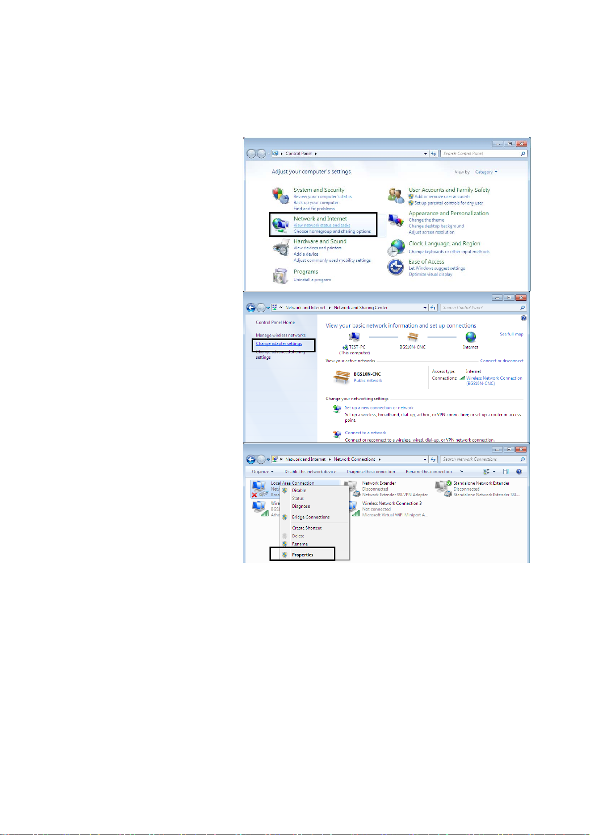
Configuring a PC in Windows 7
1. Go to Start. Click on
Control Panel.
2. Then click on Network and
Internet.
3. When the Network and
Sharing Center window
pops up, select and click on
Change adapter settings
on the left window panel.
4. Select the Local Area
Connection, and right click
the icon to select
Properties.
13
Page 18
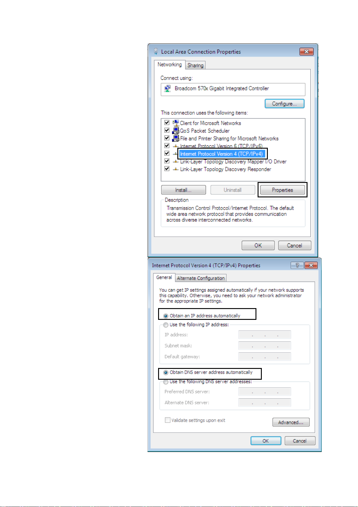
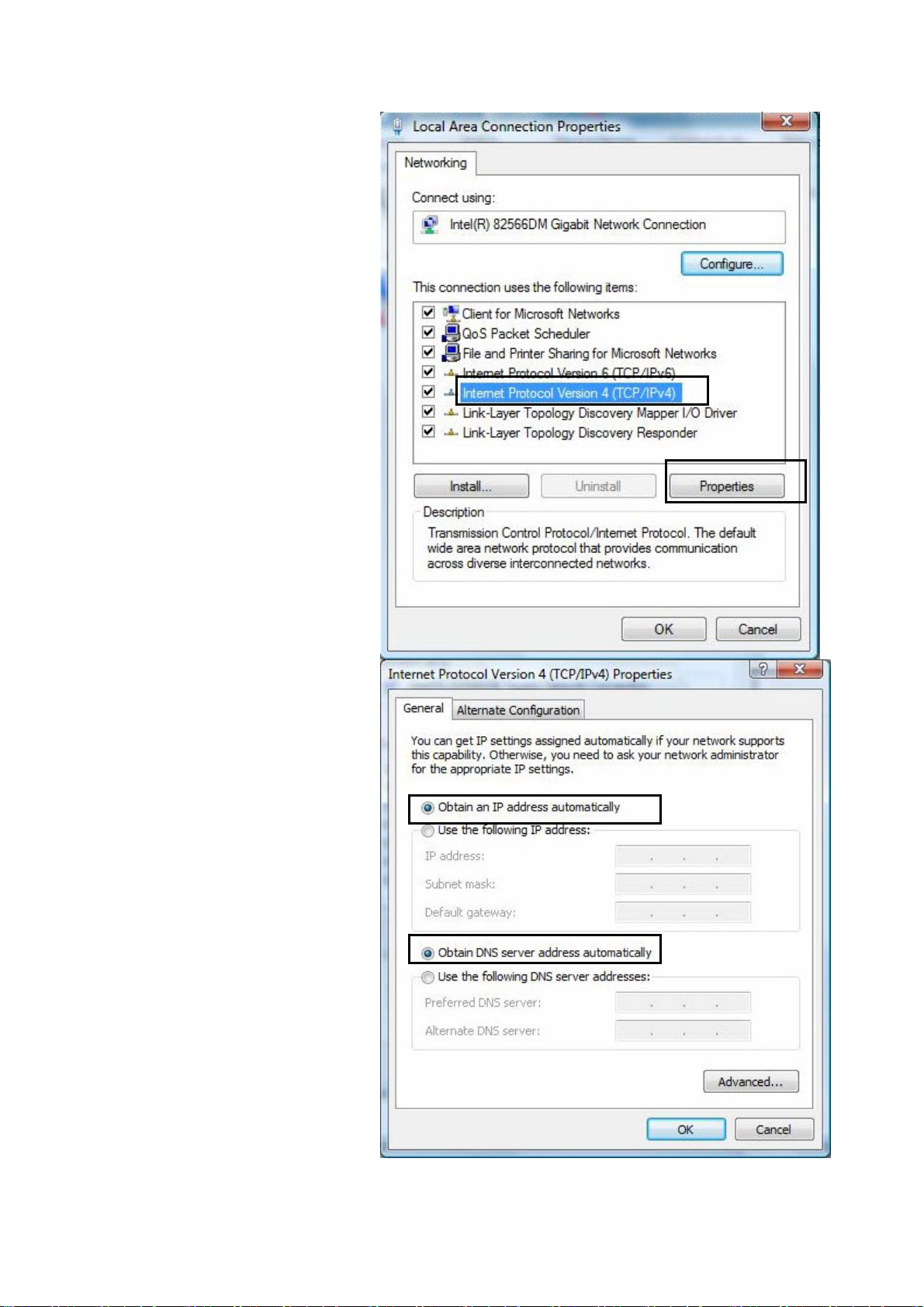
5. Select Internet Protocol
Version 4 (TCP/IPv4) then
click Properties.
6. In the TCP/IPv4 properties
window, select the Obtain
an IP address
automatically and Obtain
DNS Server address
automatically radio
buttons. Then click OK to
exit the setting.
7. Click OK again in the Local
Area Connection
Properties window to apply
the new configuration.
14
Page 19
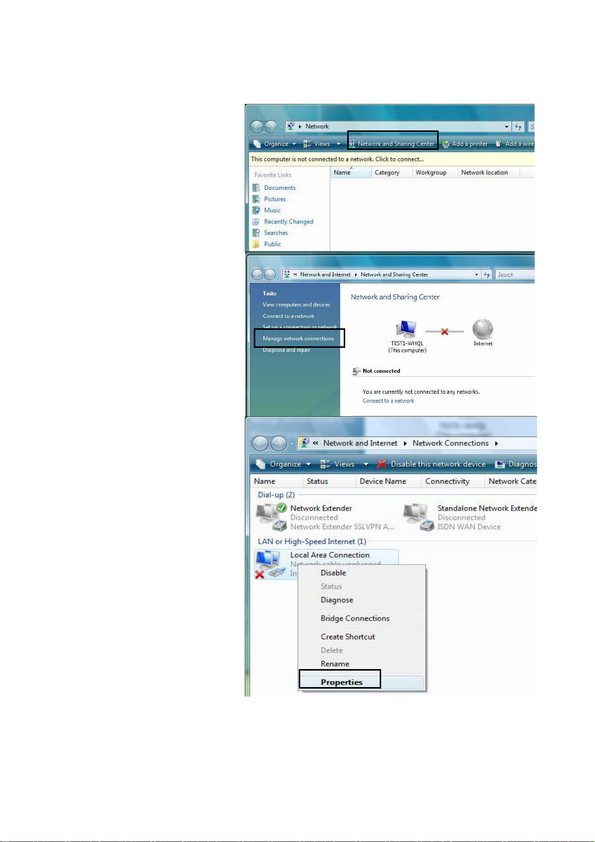
Configuring a PC in Windows Vista
1. Go to Start. Click on
Network.
2. Then click on Network and
Sharing Center at the top
bar.
3. When the Network and
Sharing Center window
pops up, select and click on
Manage network
connections on the left
window pane.
4. Select the Local Area
Connection, and right click
the icon to select
Properties.
15
Page 20
5. Select Internet Protocol
Version 4 (TCP/IPv4) then
click Properties.
6. In the TCP/IPv4 properties
window, select the Obt ain an
IP address automatically
and Obtain DNS Server
address automatically
radio buttons. Then click OK
to exit the setting.
7. Click OK again in the Local
Area Connection
Properties window to apply
the new configuration.
16
Page 21
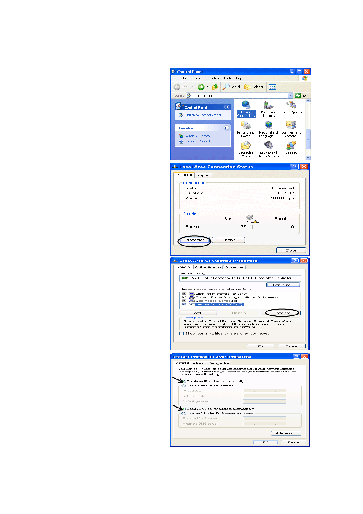
Configuring a PC in Windows XP
1. Go to Start. Click on Control Panel.
2. Then click on Network and Internet.
3. In the Local Area Connection Status
window, click Properties.
4. Select Internet Protocol (TCP/IP) and
click Properties.
5. Select the Obtain an IP address
automatically and the Obtain DNS
server address automatically radio
buttons.
6. Click OK to finish the configuration.
17
Page 22
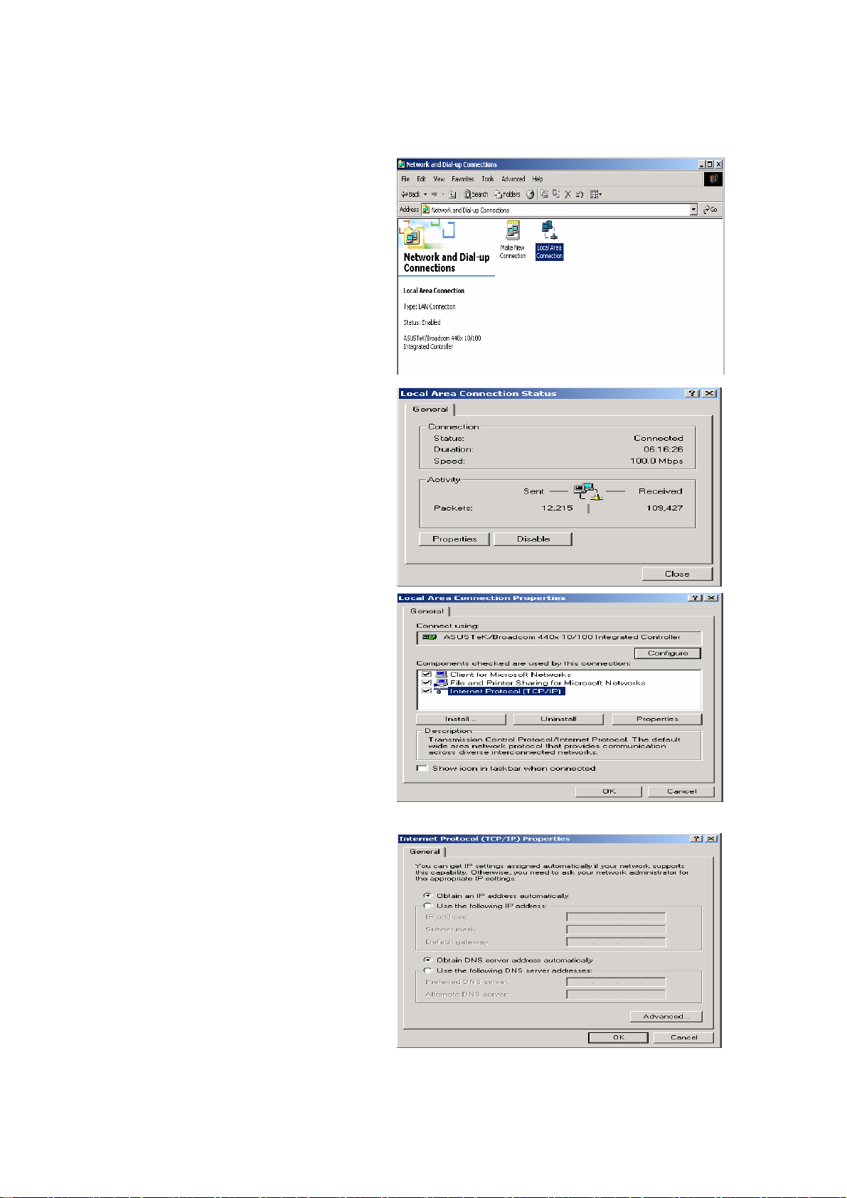
Configuring a PC in Windows 2000
1. Go to Start / Settings / Control Panel.
In the Control Panel, double-click on
Network and Dial-up Connections.
2. Double-click Local Area Connection.
3. In the Local Area Connection Status
window click Properties.
4. Select Internet Protocol (TCP/IP) and
click Properties.
5. Select the Obtain an IP address
automatically and the Obtain DNS
server address automatically radio
buttons.
6. Click OK to finish the configuration.
18
Page 23
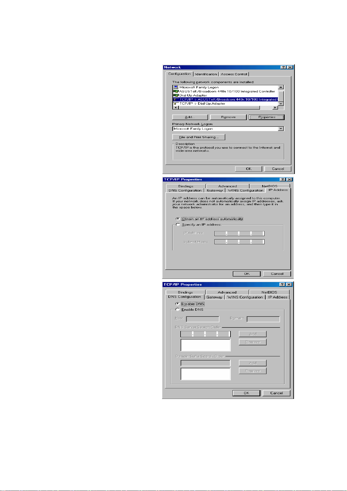
Configuring PC in Windows 98/Me
1. Go to Start / Settings / Control Panel.
In the Control Panel, double-click on
Network and choose the
Configuration tab.
2. Select TCP/IP ->NE2000 Compatible,
or the name of your Network Interface
Card (NIC) in your PC.
3. Select the Obtain an IP address
automatically radio button.
4. Then select the DNS Configuration
tab.
5. Select the Disable DNS radio button
and click OK to finish the configuration.
19
Page 24
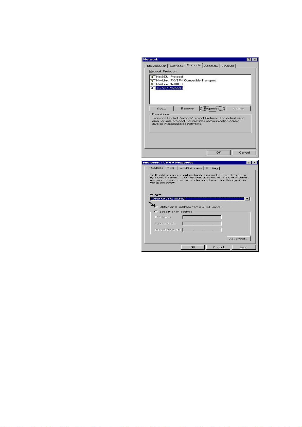
Configuring PC in Windows NT4.0
1. Go to Start / Settings / Control Panel.
In the Control Panel, double-click on
Network and choose the Protocols tab.
2. Select TCP/IP Protocol and click
Properties.
3. Select the Obtain an IP address from a
DHCP server radio button and click OK.
20
Page 25
Factory Default Settings
Before configuring the BiPAC 6200NXL router, you need to know the following default settings.
Web Interface: (Username and Password)
Username: admin
Password: admin
The default username and password are “admin” and “admin” respectively.
Attention
Device LAN IP settings
IP Address: 192.168.1.254
If you ever forget the username/password to login to the router, you
may press the RESET button up to 6 seconds then release it to restore
the factory default settings.
Caution: After pressing the RESET button for more than 6 seconds
then release it, to be sure you power cycle the device again.
Subnet Mask: 255.255.255.0
ISP setting in WAN site
Obtain an IP Address Automatically
DHCP server
DHCP server is enabled.
Start IP Address: 192.168.1.100
IP pool counts: 100
LAN and WAN Port Addresses
The parameters of LAN and WAN port s are preset at the factory. The default values are shown below.
LAN Port WAN Port
IP address
192.168.1.254
The DHCP function is
enabled to automatically get
Subnet Mask
DHCP server function
IP addresses for
distribution to PCs
255.255.255.0
Enabled in ports 1, 2 and 3
100 IP addresses continuing
from 192.168.1.100 through
the WAN port configuration
from the ISP.
192.168.1.199
21
Page 26

Information from your ISP
Before configuring this device, you have to check with your ISP (Internet Service Provider) what kind
of services are provided, such as PPPoE, Obtain an IP Address Automatically, Fixed IP address.
Gather the information as illustrated in the following table and keep it for reference.
PPPoE Username, Password, Service Name, and Domain Name
System (DNS) IP address (it can be automatically assigned
by your ISP when you connect or be set manually).
Obtain an IP Address
Automatically
Fixed IP Address IP address, Subnet mask, Gateway address, and Domain
DHCP Client (it can be automatically assigned by your ISP
when you connect or be set manually).
Name System (DNS) IP address (it is fixed IP address).
22
Page 27

Configuring with your Web Browser
Open your web browser, enter the IP address of your router, which by default is 192.168.1.254, and
click “Go”, a user name and password window prompt appears. Enter the user name and password
that your administrator has set for you and select the Account Type, then click Login. When you are
authorised, you will access to the router.The default username and password are “admin” and
“admin”.
Congratulations! You have successfully logged on to your BiPAC 6200NXL Router!
23
Page 28

Chapter 4: Basic Configuration
Once you have logged on to your BiPAC 6200NXL Router via your web browser , you can begin to set
it up according to your requirements. On the configuration homepage, the left navigation pane links
you directly to the setup pages, which include:
Advanced (Switch to Advanced Configuration mode)
Status
Quick Start
WAN
WLAN
Language
24
Page 29
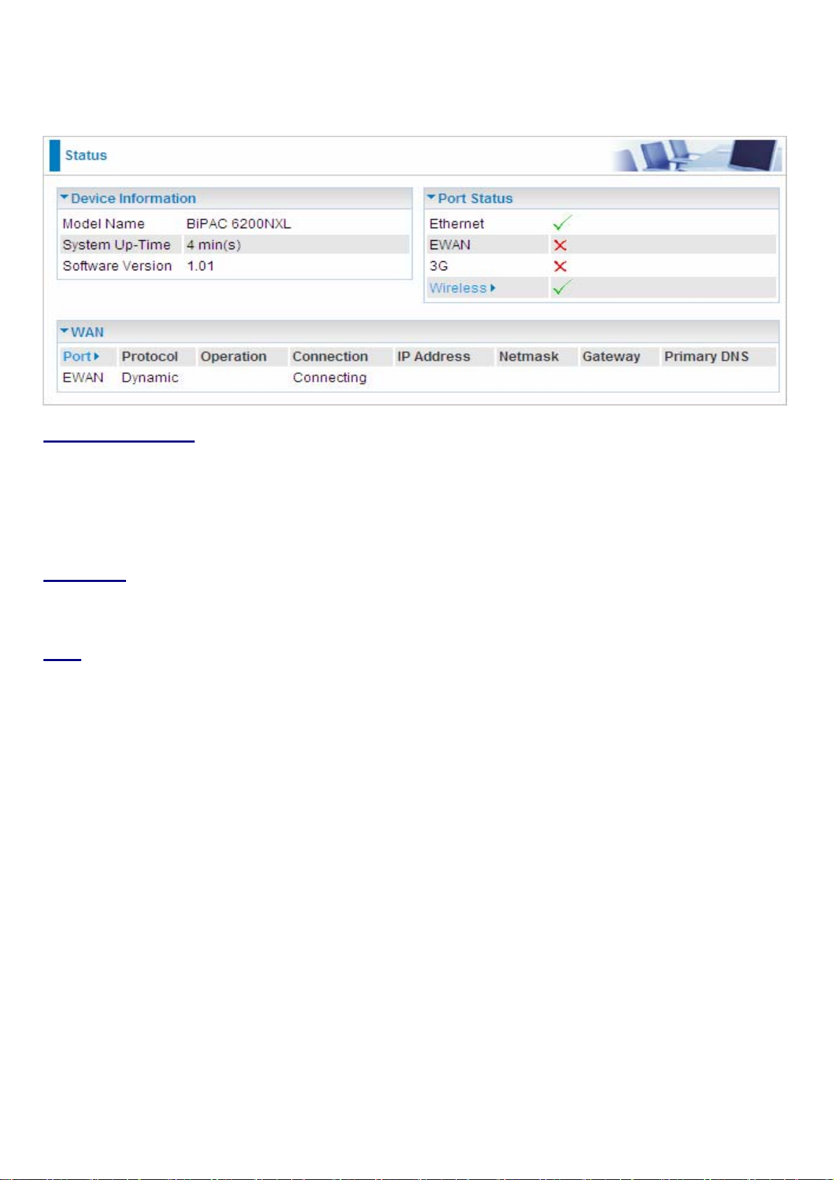
Status
Device Information
Model Name: Provide a name for the router for identification purposes.
System Up-Time: Records system up-time.
Software Version: Firmware version.
Port Status
Port Status:User can look up to see if they are connected to Ethernet, EWAN, and Wireless.
WAN
Port: Name of the WAN connection.
Protocol: PPPoE, DCHP Client or Static IP
Operation: Current available operation.
Connection: The current connection status.
Netmask: WAN port IP subnet mask.
Gateway: The IP address of the default gateway.
IP Address: WAN port IP address.
Primary DNS: The IP address of the primary DNS server.
25
Page 30
Quick Start
Set Wireless configuration
WLAN Service: Default setting is set to Enable.
ESSID: The ESSID is the unique name of a wireless access point (AP) to be distinguished from
another. For security purpose, change to a unique ID name to the AP which is already built-in to the
router’s wireless interface. It is case sensitive and must not excess 32 characters. Make sure your
wireless clients have exactly the ESSID as the device, in order to get connected to your network.
Channel ID: Select the ID channel that you would like to use.
Security Mode: You can disable or enable with WPA or WEP for protecting wireless network. The
default mode of wireless security is Disable.
26
Page 31

WAN
EWAN
3G
APN: An APN is similar to a URL on the WWW, it is what the unit makes a GPRS / UMTS call. The
service provider is able to attach anything to an APN to create a data connection. Requirements for
APN assignment varies between different service providers. Most service providers have an internet
portal which they connect a DHCP Server to, giving you access to the internet i.e. Some 3G operators
use the APN ‘internet’ for their portal. The default value of APN is “internet”.
Username: Enter the username provided by your service provider.
Password: Enter the password provided by your service provider.
27
Page 32

Auth. Protocol: Manually specify CHAP (Challenge Handshake Authentication Protocol) or PAP
(Password Authentication Protocol) if you know which authentication type the server is using (when
acting as a client), or the authentication type you want the clients to use when tehy are connecting to
you (when acting as a server). When using PAP, the password is sent unencrypted, while CHAP
encrypts the password before sending, and also allows for challenges at different periods to ensure
that an intruder has not replaced the client.
PIN: PIN stands for Personal Identification Number. A PIN code is a numeric value used in certain
systems as a password to gain access, and authentication. In mobile phones a PIN code locks the SIM
card until you enter the correct code. If you enter the PIN code incorrectly into the phone 3 times in a
row, then the SIM card will be blocked and a PUK code will be required from your network / service
provider to unlock it.
28
Page 33

WLAN
WLAN Service: Default setting is set to Enable.
ESSID: The ESSID is the unique name of a wireless access point (AP) to be distinguished from
another. For security propose, change to a unique ID name to the AP which is already built-in to the
router’s wireless interface. It is case sensitive and must not excess 32 characters. Make sure your
wireless clients have exactly the ESSID as the device, in order to get connected to your network.
Note: ESSID is case sensitive and must not excess 32 characters.
Hide ESSID: It is function in which transmits its ESSID to the air so that when wireless client searches
for a network, router can then be discovered and recognized. Default setting is Disable.
~ Enable: Select Enable if you do not want broadcast your ESSID. When select Enable, no one
will be able to locate the Access Point (AP) of your router.
~ Disable: When Disable is selected, you can allow anybody with a wireless client to be able to
locate the Access Point (AP) of your router.
Regulation Domain: There are seven Regulation Domains for you to choose from, including North
America (N.America), Europe, France, etc. The Channel ID will be different based on this setting.
Channel ID: Select the ID channel that you would like to use.
Security Mode: You can disable or enable with WPA or WEP for protecting wireless network. The
default mode of wireless security is Disable.
Security Parameters
WPA Pre-Shared Key
WPA Shared Key: The key for network authentication. The input format is in character style and the
29
Page 34

key size should be in the range between 8 and 63 characters.
Group Key Renewal: The period of renewal time for changing the security key between wireless
client and Access Point (AP). This process is done automatically.
WPA2 Pre-Shared Key
WPA2 Shared Key: The key for network authentication. The input format is in character style and key
size should be in the range between 8 and 63 characters.
Group Key Renewal: The period of renewal time for changing the security key between wireless
client and Access Point (AP). This process is done automatically.
30
Page 35

WEP
WEP Authentication: To prevent unauthorized wireless stations from accessing data transmitted
over the network, the router offers secure data encryption, known as WEP. If you require high security
for transmissions, there are three options to select from: Open System, Share key or Both.
Default Used WEP Key: Select the encryption key ID; please refer to Key (1~4) below.
Passphrase: This is used to generate WEP keys automatically based upon the input string and a
pre-defined algorithm in WEP64 or WEP128. You can input the same string in both the AP and Client
card settings to generate the same WEP keys. Please note that you do not have to enter Key (1-4) as
below when the Passphrase is enabled.
Key (1-4): Enter the key to encrypt wireless data. To allow encrypted data transmission, the WEP
Encryption Key values on all wireless stations must be the same as the router . There are four keys for
your selection. The input format is in HEX or ASCII style, 5 and 13 ASCII codes are required for
WEP64 and WEP128 respectively no any separator is included.
31
Page 36

Chapter 5: Advanced Configuration
Once you have logged on to your BiPAC 6200NXL Router via your web browser, you can begin to set
it up according to your requirements. On the configuration homepage, the left navigation pane links
you directly to the setup pages, which include:
Basic (Switch to Basic Configuration Mode)
Status (3G Status, ARP Table, DHCP Table, System Log, Firewall Log, UPnP Portmap)
Quick Start
Configuration (LAN, WAN, System, USB Server, Firewall, QoS, Virtual Server, Time Schedule,
Wake on LAN and Advanced)
Language
The following sections provide an overview of the settings available for configuring your router.
32
Page 37

Status
Device Information
Model Name: Displays the model name.
Host Name: Provide a name for the router for identification purposes. Host Name lets you change
the router name.
System Up-Time: Records system up-time.
Current time: Set the current time. See the Time Zone section for more information.
Software Version: Firmware version.
MAC Address: The LAN MAC address.
Port Status
Port Status:User can look up to see if they are connected to Ethernet, EWAN, 3G or Wireless.
WAN
Port: Name of the WAN connection.
Operation: Current available operation.
Connection: The current connection status.
IP Address: WAN port IP address.
Net mask: WAN port IP subnet mask.
Gateway: The IP address of the default gateway.
Primary DNS: The IP address of the primary DNS server.
33
Page 38

3G Status
This section displays the 3G Card overall status with information such as the current signal strength,
statistics of current data transmission and total data transmission.
Status: The current status of the 3G card.
Signal Strength: The signal strength bar indicates the current 3G signal strength.
Network Name: The network name that the device is connected to.
Card Name: The name of the 3G card.
Card Firmware: The current firmware of the 3G card.
Card IMEI: The unique identification number that is used to identify the 3G card.
Current TX Bytes / Packets: The statistics of data transmission in bytes / packets during a call.
Current RX Bytes / Packets: The statistics of data received in bytes / packets during a call.
Total TX Bytes / Packets: The statistics of total data transmission in bytes / packets since system
ready.
Total RX Bytes / Packets: The statistics of total data received in bytes / packets since system ready.
Amount used: Show the traffic or hours has been used.
Billing preiod: The day from which the fee is charged.
34
Page 39

ARP Table
This section displays the router’s ARP (Address Resolution Protocol) Table, which shows the mapping
of Internet (IP) addresses to Ethernet (MAC) addresses. This is useful as a quick way of determining
the MAC address of the network interface of your PCs to use with the router’s Firewall - MAC
Address Filter function. See the Firewall section of this manual for more information on this feature.
IP Address: It is IP Address of internal host that join this network.
MAC Address: The MAC address of internal host.
Interface: The ARP interface.
Static ARP: The state for ARP.
DHCP Table
IP Address: The current corresponding DHCP-assigned dynamic IP address of the device.
MAC Address: The MAC Address of internal DHCP client host.
Client Host Name: The Host Name of internal DHCP client.
Register Information: Register time information.
35
Page 40

System Log
Display system logs accumulated up to the present time. You can trace historical information with this
function.
Firewall Log
Firewall Log displays log information of any unexpected action with your firewall settings. This page
displays the router’s Firewall Log entries. The log shows log entries when you have enabled Intrusion
Detection or Block WAN PING in the Configuration - Firewall section of the interface. Please see the
Firewall section of this manual for more details on how to enable Firewall logging.
36
Page 41

UPnP Portmap
The section lists all port-mapping established using UPnP (Universal Plug and Play). Please see the
Advanced section of this manual for more details on UPnP and the router’s UPnP configuration
options.
37
Page 42

Quick Start
3G
Connect mode: 3G
TEL No.: The dial string to make a GPRS / 3G user internetworking call. It may be provided by your
mobile service provider.
Username: Enter the username provided by your service provider.
APN: An APN is similar to a URL on the WWW, it is what the unit makes a GPRS / UMTS call. The
service provider is able to attach anything to an APN to create a data connection. Requirements for
APN assignment varies between different service providers. Most service providers have an internet
portal which they connect a DHCP Server to, giving you access to the internet i.e. Some 3G operators
use the APN ‘internet’ for their portal. The default value of APN is “internet”.
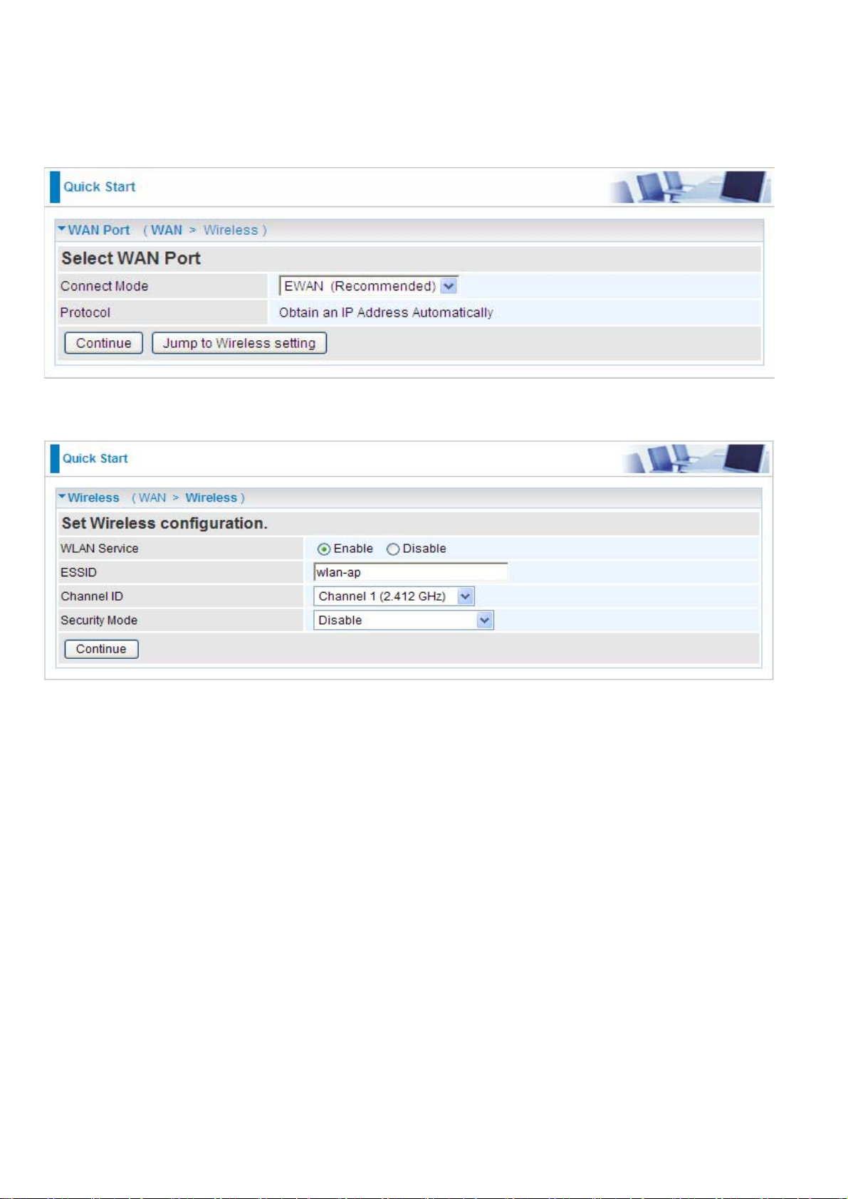
EWAN
Connect mode: EWAN
Protocol: The current protocol in the device.
Click on Continue to choose the Protocol to connect with EWAN or click Jump to Wireless Setting to
use Protocol: Obtain an IP Address Automatically to connect and setup wireless settings at the same
time.
38
Page 43

Obtain an IP Address Automatically
When connecting to the ISP, BiPAC 6200NXL also functions as a DHCP client. BiPAC 6200NXL can
automatically obtain an IP address, subnet mask, gateway address, and DNS server addresses if the
ISP assigns this information via DHCP.
Protocol: The current protocol in the device
Click on the Continue button and wait for your connection to be connected.
If connection is successful the following image will be shown.
39
Page 44

Fixed IP Address
Select this option to set static IP information. You will need to enter in the Connection type, IP address,
Netmask, and gateway address, provided to you by your ISP. Each IP address entered in the fields
must be in the appropriate IP form, which are four IP octets separated by a dot (x.x.x.x). The Router
will not accept the IP address if it is not in this format.
Protocol: The current ATM protocol in the device
IP Address: Your WAN IP address. Leave this at 0.0.0.0 to automatically obtain an IP address from
your ISP.
Netmask: The default is 0.0.0.0. User can change it to other such as 255.255.255.0.Type the subnet
mask assigned to you by your ISP (if given).
Gateway: You must specify a gateway IP address (supplied by your ISP)
Click on the Continue button and wait for your connection to be connected.
If connection is successful the following image will be shown.
40
Page 45

PPPoE
PPPoE (PPP over Ethernet) provides access control in a manner similar to dial-up services using PPP.
Protocol: The current ATM protocol in the device
Username: Enter the username provided by your ISP. You can input up to 128 alphanumeric
characters (case sensitive). This is in the format of “username@ispname” instead of simply
“username”.
Password: Enter the password provided by your ISP. You can input up to 128 alphanumeric
characters (case sensitive).
Service Name: Enter a name for this connection.
IP Address: Your WAN IP address. Leave this at 0.0.0.0 to automatically obtain an IP address from
your ISP.
Auth. Protocol: Default is Auto. Your ISP advises on using Chap or Pap.
Click on the Continue button and wait for your connection to be connected.
If connection is successful the following image will be shown.
41
Page 46

Set Wireless configuration
WLAN Service: Default setting is set to Enable.
ESSID: The ESSID is the unique name of a wireless access point (AP) to be distinguished from
another. For security propose, change to a unique ID name to the AP which is already built-in to the
router’s wireless interface. It is case sensitive and must not excess 32 characters. Make sure your
wireless clients have exactly the ESSID as the device, in order to get connected to your network.
Channel ID: Select the ID channel that you would like to use.
Security Mode: You can disable or enable with WPA or WEP for protecting wireless network. The
default mode of wireless security is Disable.
42
Page 47

Configuration
Click this item to access the following sub-items that configure the 3G router: LAN, WAN, System,
USB, Firewall, QoS, Virtual Server, Wake on LAN, Time Schedule and Advanced.
These functions are described in the following sections.
LAN (Local Area Network)
A Local Area Network (LAN) is a shared communication system to which many computers are
attached and is limited to the immediate area, usually the same building or floor of a building.
There are six items within the LAN section: Ethernet, IP Alias, Wireless, Wireless Security, WPS
and DHCP Server.
43
Page 48

Ethernet
The router supports more than one Ethernet IP addresses in the LAN, and with distinct LAN subnets
through which you can access the Internet at the same time. Users usually only have one subnet in
their LAN. The default IP address for the router is 192.168.1.254.
IP Address: The default IP on this router.
Netmask: The default subnet mask on this router.
RIP: RIP v1, RIP v2, RIP v1+v2 and RIP v2 Multicast.
IP Alias
This function allows the creation of multiple virtual IP interfaces on this router. It helps to connect two
or more local networks to the ISP or remote node. In this case, an internal router is not required.
IP Address: Specify an IP address on this virtual interface.
Netmask: Specify a subnet mask on this virtual interface.
44
Page 49

Wireless
Parameters
WLAN Service: Default setting is set to Enable.
Mode: The default setting is 802.11g+n (Mixed mode). If you do not know or have both 11g and 11n
devices in your network, then keep the default in mixed mode. From the drop-down manual, you can
select 802.11g if you have only 11g card. If you have only 11b card, then select 802.11b. If you have
only 11n card, then select 802.11n.
Number of Active SSID: Number of SSID you can choose.
SSID No.: The SSID you choose.
ESSID: The ESSID is the unique name of a wireless access point (AP) to be distinguished from
another. For security propose, change to a unique ID name to the AP which is already built-in to the
router’s wireless interface. It is case sensitive and must not excess 32 characters. Make sure your
wireless clients have exactly the ESSID as the device, in order to get connected to your network.
Note: ESSID is case sensitive and must not excess 32 characters.
Hide ESSID: It is function in which transmits its ESSID to the air so that when wireless client searches
45
Page 50

for a network, router can then be discovered and recognized. Default setting is Disable.
~ Enable: Select Enable if you do not want broadcast your ESSID. When select Enable, no one
will be able to locate the Access Point (AP) of your router.
~ Disable: When Disable is selected, you can allow anybody with a wireless client to be able to
locate the Access Point (AP) of your router.
Regulation Domain: There are seven Regulation Domains for you to choose from, including North
America (N.America), Europe, France, etc. The Channel ID will be different based on this setting.
Channel ID: Select the ID channel that you would like to use.
Channel Wdith: Select either 20 MHz or 20/40 MHz for the channel bandwidth. The higher the
bandwidth the better the performance will be.
Tx Power Level: It is function that enhances the wireless transmitting signal strength. User may
adjust this power level from minimum 0 up to maximum 100.
Note: The Power Level maybe different in each access network user premises environment and
choose the most suitable level for your network.
AP MAC Address: It is a unique hardware address of the Access Point.
AP Firmware Version: The Access Point firmware version.
WPS service: Enable / disable
WPS State: Current WPS state in AP. It is be used for WCN (Windows Connect Now).
~ Configured: This AP is be configured via WPS. It is not allow to configure via WCN.
~ Unconfigured: This AP is un-configured via WPS. It can be configure via WCN.
WMM: This feature works concurrently with QoS that enables the system to prioritize the flow of data
packets according to 4 categories: Voice, Video, Best Efforts and Background.
~ Enable: Click to activate WMM feature.
~ Disable: Click to deactivate WMM feature.
Wireless Distribution System (WDS)
It is a wireless access point mode that enables wireless link and communication with other access
point. It is easy to be installed, simply define the peer’s MAC address of the connected AP. WDS takes
advantages of cost saving and flexibility which no extra wireless client device is required to bridge
between two access points and extending an existing wired or wireless infrastructure network to
create a larger network.
WDS Service: The default setting is Disable. Check Enable radio button to activate this function.
1. Peer WDS MAC Address: It is the associated AP’s MAC Address. It is important that your peer’s
AP must include your MAC address in order to acknowledge and communicate with each other.
2. Peer WDS MAC Address: It is the second associated AP’s MAC Address.
3. Peer WDS MAC Address: It is the third associated AP’s MAC Address.
4. Peer WDS MAC Address: It is the fourth associated AP’s MAC Address.
Note: For MAC Address, Semicolon (;) or Dash (-) must be included.
46
Page 51

Wireless Security
You can disable or enable with WPA or WEP for protecting wireless network. The default mode of
wireless security is Disable.
SSID No.: Choose the SSID you want to set.
Security Mode: There are five security modes for you to choose.
WPA Pre-Shared Key
WPA Algorithms: TKIP (Temporal Key Integrity Protocol) / AES (Advanced Encryption Standard)
utilizes a stronger encryption method and incorporates Message Integrity Code (MIC) to provide
protection against hackers.
WPA Shared Key: The key for network authentication . The input format is in character style and key
size should be in the range between 8 and 63 characters.
Group Key Renewal: The period of renewal time for changing the security key automatically between
wireless client and Access Point (AP).
47
Page 52

WPA2 Pre-Shared Key
WPA2 Algorithms: TKIP (Temporal Key Integrity Protocol) / AES (Advanced Encryption Standard)
utilizes a stronger encryption method and incorporates Message Integrity Code (MIC) to provide
protection against hackers.
WPA2 Shared Key: The key for network authentication. The input format is in character style and key
size should be in the range between 8 and 63 characters.
Group Key Renewal: The period of renewal time for changing the security key automatically between
wireless client and Access Point (AP).
48
Page 53

WEP
WEP Authentication: To prevent unauthorized wireless stations from accessing data transmitted
over the network, the router offers secure data encryption, known as WEP. If you require high security
for transmissions, there are three options to select from: Open System, Share key or Both.
Default Used WEP Key: Select the encryption key ID; please refer to Key (1~4) below.
Passphrase: This is used to generate WEP keys automatically based upon the input string and a
pre-defined algorithm in WEP64 or WEP128. You can input the same string in both the AP and Client
card settings to generate the same WEP keys. Please note that you do not have to enter Key (1-4) as
below when the Passphrase is enabled.
Key (1-4): Enter the key to encrypt wireless data. To allow encrypted data transmission, the WEP
Encryption Key values on all wireless stations must be the same as the router . There are four keys for
your selection. The input format is in HEX or ASCII style, 5 and 13 ASCII codes are required for
WEP64 and WEP128 respectively
no any separator is included.
49
Page 54

WPS
WPS (WiFi Protected Setup) feature is a standard protocol created by Wi-Fi Alliance. This feature
greatly simplifies the steps needed to create a Wi-Fi network for a residential or an office setting. WPS
supports 2 types of configuration methods which are commonly known among consumers: PIN
Method & PBC Method.
50
Page 55

Wi-Fi Network Setup
PIN Method: Configure AP as Registrar
1. Jot down the client’s Pin (e.g. 16837546).
2. Enter the Enrollee’s PIN number and then press Start.
3. Launch the wireless client’s WPS utility (eg. Ralink Utility). Set the Configure Mode as Enrollee,
press the WPS button on the top bar, select the AP (eg. wlan-ap) from the WPS AP List column.Then
press the PIN button located on the middle left of the page to run the scan.
51
Page 56

4. The client’s SSID and security setting will now be configured to match the SSID and security setting
of the registrar.
52
Page 57

PIN Method: Configure AP as Enrollee
1. In the WPS configuration page, change the Role to Enrollee. Then press Start.
2. Jot down the WPS PIN (e.g. 25879810).
3. Launch the wireless client’s WPS utility (e.g. Ralink Utility). Set the Config Mode as Registrar. Enter
the PIN number in the PIN Code column then choose the correct AP (eg. wlan-ap) from the WPS AP
List section before pressing the PIN button to run the scan.
53
Page 58

4. The router’s (AP’s) SSID and security setting will now be configured to match the SSID and security
setting of the registrar.
54
Page 59

5. Now to make sure that the setup is correctly done, cross check to see if the SSID and the security
setting of the registrar setting match with the parameters found on both Wireless Configuration and
Wireless Security Configuration page.
55
Page 60

the parameters on both Wireless Configuration and Wireless Security Configuration page are as
follows:
56
Page 61

PBC Method:
1. Press the PBC button of the AP.
2. Launch the wireless client’s WPS Utility (eg. Ralink Utility). Set the Config Mode as Enrollee. Then
press the WPS button and choose the correct AP (eg. wlan-ap) from the WPS AP List section before
pressing the PBC button to run the scan.
57
Page 62

3. When the PBC button is pushed, a wireless communication will be established between your router
and the PC. The client’s SSID and security setting will now be configured to match the SSID and
security setting of the router.
58
Page 63

Wi-Fi Network Setup with Windows Vista WCN:
1. Jot down the AP PIN from the Web (eg. 25879810).
2. Access the Wireless configuration of the web GUI. Set the WPS State to Unconfigured then click
Apply.
59
Page 64

3. In your Vista operating system, access the Control Panel page, then select Network and Internet >
View Network Computers and Devices. Double click on the router icon and enter the AP PIN in the
column provided then press Next.
4. Enter the AP SSID then click Next.
60
Page 65

5. Enter the passphrase then click Next.
6. When you have come to this step, you will have completed the Wi-Fi network setup using the built-in
WCN feature in Windows Vista.
61
Page 66

DHCP Server
You can disable or enable the DHCP (Dynamic Host Configuration Protocol) server or enable the
router’s DHCP relay functions. The DHCP protocol allows your router to dynamically assign IP
addresses to PCs on your network if they are configured to obtain IP addresses automatically.
DHCP Server Mode: Disable
To disable the router’s DHCP Server , check Disabled and then click Apply . When the DHCP Server is
disabled, you will need to manually assign a fixed IP address to each PC on your network, and set the
default gateway for each PC to the IP address of the router (the default is 192.168.1.254).
62
Page 67

DHCP Server Mode: DHCP Server
To configure the router ’s DHCP Server, check DHCP Server. You can then configure parameters of
the DHCP Server including the IP pool (starting IP address and ending IP address to be allocated to
PCs on your network), lease time for each assigned IP address (the period of time the IP address
assigned will be valid), DNS IP address and the gateway IP address. These details are sent to the
DHCP client (i.e. your PC) when it requests an IP address from the DHCP server. Click Apply to
enable this function. If you check “Use Router as a DNS Server”, the 3G Router performs the domain
name lookup, finds the IP address from the outside network automatically and forwards it back to the
requesting PC in the LAN (your Local Area Network).
DHCP Server Mode: DHCP Relay
If you check DHCP Relay and then you must enter the IP address of the DHCP server which assigns
an IP address back to the DHCP client in the LAN. Use this function only if advised to do so by your
network administrator or ISP. Click Apply to enable this function.
63
Page 68

WAN (Wide Area Network)
A WAN (Wide Area Network) is an outside connection to another network or the Internet. There are
two items within the WAN section: WAN interface and WAN Profile.
WAN Interface(EWAN)
Connect Mode: Select the main port from the drop-down menu.
Click Apply to confirm the change.
WAN Interface(3G)
Connect Mode: Select the main port from the drop-down menu.
Click Apply to confirm the change.
64
Page 69

WAN Interface(Dual WAN)
Connect Mode: Select the Dual WAN from the drop-down menu.
Main WAN: Choose EWAN or 3G as main WAN. Click the link to go to WAN Profile page to configure
its parameters.
Backup WAN: Choose the left as b acku p W AN. Click the link to go to WAN Profile page to configure its
parameters.
Connectivity Decision: Enter the value for the times when probing failed to switch backup port.
Failover Probe Cycle: Set the time duration for the Failover Probe Cycle to determine when the
router will switch to the backup connection (backup port) once the main connection (main port) fails.
Note: The time values entered in Failover Probe Cycle field is set for each probe cycle and
decided by Probe Cycle duration multiplied by Connection Decision value (e.g. 60 seconds are
multiplied by 12 seconds and 5 consecutive fails).
Detect Rule (either one):
• Ping Gateway: It will send ping packet to gateway and wait response from gateway in every
“Probe
Cycle”.
• Ping Host: It will send ping packet to specific host and wait response in every “Probe Cycle”.
The host must be an IP address.
Click Apply to confirm the change.
65
Page 70

WAN Profile
Main Port – EWAN
BiP AC 6200NXL of fers a W AN port to connect to Cable Modems and fiber optic lines. This alternative,
yet faster method to connect to the internet will provide users with more flexibility to get online.
Obtain an IP Address Automatically (EWAN)
When connecting to the ISP, BiPAC 6200NXL also functions as a DHCP client. BiPAC 6200NXL can
automatically obtain an IP address, Netmask, gateway address, and DNS server addresses if the ISP
assigns this information via DHCP.
Line Speed: Set the downstream and upstream of your connection in kilobytes per second. The
connection speed is used by QoS settings.
NAT: The NAT (Network Address Translation) feature allows multiple users to access the Internet
through a single ISP account, sharing a single IP address. If users on your LAN have public IP
addresses and can access the Internet directly, the NAT function can be disabled.
Obtain DNS Automatically: Select this check box to use DNS.
Primary DNS/ Secondary DNS: Enter the IP addresses of the DNS servers. The DNS servers are
passed to the DHCP clients along with the IP address and the netmask.
MAC Spoofing: Select Enable and enter a MAC address that will temporarily change your router’s
MAC address to the one you have specified in this field. Leave it as Disabled if you do not wish to
change the MAC address of your router.
66
Page 71

PPPoE (EWAN)
PPPoE (PPP over Ethernet) provides access control in a manner similar to dial-up services using PPP.
Username: Enter the username provided by your ISP. You can input up to 128 alphanumeric
characters (case sensitive). This is in the format of “username@ispname” instead of simply
“username”.
Password: Enter the password provided by your ISP. You can input up to 128 alphanumeric
characters (case sensitive)
Service Name: This item is for identification purposes. If it is required, your ISP provides you the
information. Maximum input is 15 alphanumeric characters.
NAT: The NAT (Network Address Translation) feature allows multiple users to access the Internet
through a single ISP account, sharing a single IP address. If users on your LAN have public IP
addresses and can access the Internet directly, the NAT function can be disabled.
IP Address: Your WAN IP address. Leave this at 0.0.0.0 to automatically obtain an IP address from
your ISP.
Auth. Protocol: Default is Auto. Your ISP advises on using Chap or Pap.
Obtain DNS Automatically: Select this check box to use DNS.
Primary DNS/ Secondary DNS: Enter the IP addresses of the DNS servers. The DNS servers are
passed to the DHCP clients along with the IP address and the Netmask.
Connection:
~ Always on: If you want the router to establish a PPPoE session when starting up and to
automatically re-establish the PPPoE session when disconnected by the ISP.
~ Connect to Demand (un-select Always On): If you want to establish a PPPoE session only
when there is a packet requesting access to the Internet (i.e. when a program on your computer
attempts to access the Internet). In this mode, you must set Idle Timeout value at same time.
Idle Timeout: Auto-disconnect the broadband firewall gateway when there is no activity on the line for
a predetermined period of time. The minimum value is 10 minutes.
MTU: Maximum Transmission Unit. The size of the largest datagram (excluding media-specific
headers) an IP attempts to send through the interface.
67
Page 72

Fixed IP Address (EWAN)
Select this option to set static IP information. You will need to enter in the Connection type, IP address,
netmask, and gateway address, provided to you by your ISP. Each IP address entered in the fields
must be in the appropriate IP form, which is four IP octet s sep arated by a dot (x.x.x.x). The Router will
not accept the IP address if it is not in this format.
Line Speed: Set the downstream and upstream of your connection in kilobytes per second. The
connection speed is used by QoS settings.
NAT: The NAT (Network Address Translation) feature allows multiple users to access the Internet
through a single IP account, sharing a single IP address. If users on your LAN have public IP
addresses and can access the Internet directly, the NAT function can be disabled.
IP Address: Your WAN IP address. Leave this at 0.0.0.0 to automatically obtain an IP address from
your ISP.
IP Netmask: The default is 0.0.0.0. User can change it to other such as 255.255.255.0.Type the
netmask assigned to you by your ISP (if given).
Gateway: You must specify a gateway IP address (supplied by your ISP)
Obtain DNS Automatically: Select this check box to use DNS.
Primary DNS/ Secondary DNS: Enter the IP addresses of the DNS servers. The DNS servers are
passed to the DHCP clients along with the IP address and the netmask.
MAC Spoofing: Select Enable and enter a MAC address that will temporarily change your router’s
MAC address to the one you have specified in this field. Leave it as Disabled if you do not wish to
change the MAC address of your router.
68
Page 73

Main Port - 3G
The router allows you to insert a 3G/HSDPA card to its USB slot, enabling you to use a 3G/ HSDPA,
UMTS, EDGE, GPRS, or GSM Internet connection, makes downstream rates of to 14.4 Mbps*.
ISP Mode: Choose 3G service provider.
TEL No.: The dial string to make a GPRS / 3G user internetworking call. It may be provided by your
mobile service provider.
APN: An APN is similar to a URL on the WWW, it is what the unit makes a GPRS / UMTS call. The
service provider is able to attach anything to an APN to create a data connection. Requirements for
APN assignment varies between different service providers. Most service providers have an internet
portal which they connect a DHCP Server to, giving you access to the internet i.e. Some 3G operators
use the APN ‘internet’ for their portal. The default value of APN is “internet”.
Username: Enter the username provided by your service provider.
Password: Enter the password provided by your service provider.
Auth. Protocol: Manually specify CHAP (Challenge Handshake Authentication Protocol) or PAP
(Password Authentication Protocol) if you know which authentication type the server is using (when
acting as a client), or the authentication type you want the clients to use when tehy are connecting to
you (when acting as a server). When using PAP, the password is sent unencrypted, while CHAP
encrypts the password before sending, and also allows for challenges at different periods to ensure
that an intruder has not replaced the client.
MTU: Maximum Transmission Unit. The size of the largest datagram (excluding media-specific
headers) that IP will attempt to send through the interface.
69
Page 74

PIN: PIN stands for Personal Identification Number. A PIN code is a numeric value used in certain
systems as a password to gain access, and authentication. In mobile phones a PIN code locks the
SIM card until you enter the correct code. If you enter the PIN code incorrectly into the phone 3 times
in a row , then the SIM card will be blocked and a PUK code will be required from your network / service
provider to unlock it.
Note: If you enter an incorrect PIN code three times in a row, your SIM card will be blocked. In this
case, please enter your PUK code (it can be supplied by your service provider) and then re-enter your
PIN.
Connection:
Always On: The router will make UMTS/GPRS call when starting up. Enabling Always On, will give
you an option of Keep Alive.
Connect on Demand: If you want to make UMTS/GPRS call only when there is a packet re- questing
access to the Internet (i.e. when a program on your computer attempts to access the Internet). In this
mode, you must set Idle Timeout value at same time. Enabling Connect on Demand will give you an
option of Idle Timeout.
Idle Timeout: Auto-disconnect the connection when there is no activity on this call for a
predetermined period of time. The default value is 10 seconds.
Obtain DNS Automatically: Select this checkbox to use DNS.
Primary DNS/ Secondary DNS: Enter the IP addresses of the DNS servers. The DNS servers are
passed to the DHCP clients along with the IP address and the subnet mask.
Note: If you don’t know how to set these values and please keep them untouched.
70
Page 75

Click Usage Allowance to go to the Usage Allowance configuration page.
In order to query online time or volume used, you can set the following options.
Mode: Two methods are provided, that is, Volume-based and Time-based.
Volume-based: If choosing Volume-based, you can view the volume you have used.
Only Download: Only make statistics of Download Traffic.
Only Upload: Only make statistics of Upload Traffic.
Download and Upload: Make statistics of both Download and Upload Traffic.
71
Page 76

Time-based: If choosing Time-based, you can view the online hours you have used.
You can also assign the billing period.
Over usage allowance action: If the online time or traffic you have used exceeds the usage
allowance you set. The system will do the followings operations.
Save the statistics to ROM: Choose the time interval for saving statistics. You can choose to save for
Every one hour or Disable the function.
72
Page 77

System
There are five items within the System section: Time Zone, Firmware Upgrade, Backup/Restore,
Restart, User Management and Mail Alert.
Time Zone
The router does not have a real time clock on board; instead, it uses the Simple Network Time Protocol
(SNTP) to get the current time from an SNTP server outside your network. Choose your local time
zone, click Enable and click the Apply button. After a successful connection to the Internet, the router
retrieves the correct local time from the SNTP server you have specified. If you prefer to specify an
SNTP server other than those in the drop-down list, simply enter its IP address as shown above. Your
ISP may provide an SNTP server for you to use.
Resync Period (in minutes) is the periodic interval the router waits before it resynchronizes the
router’s time with that of the specified SNTP server. To avoid unnecessarily increasing the load on
your specified SNTP server you should keep the poll interval as high as possible – at the absolute
minimum every few hours or even days.
73
Page 78

Firmware Upgrade
Your router’s “firmware” is the software that allows it to operate and provides all its functionality. Think
of your router as a dedicated computer, and the firmware as the software it runs. Over time this
software may be improved and modified. Your router allows you to upgrade the software it runs to take
advantage of these changes.
Clicking on Browse allows you to select the new firmware image file you have downloaded to your PC.
Once the correct file is selected, click Upgrade to update the firmware in your router.
Restart Device with: To choose “Factory Default Settings” or “Current Settings” which uses your
current setting on the new firmware (it is highly advised to use Factory Default Settings over Current
Settings for a clean firmware upgrade).
New Firmware Image: Type in the location of the file you wish to upload in this field or click Browse…
to locate it.
Browse…: Click Browse… to find the file with the .afw file extension that you wish to upload.
Remember that you must decompress compressed (.zip) files before you can upgrade from the file.
Upgrade: Click upgrade to begin the upload process. This process may take up to three minutes.
Do not power down the router or interrupt the firmware upgrade while it is
still in process. Improper operation may damage the router. Please see
section 2.4 for emergency recovery procedures.
Warning
74
Page 79

Backup / Restore
These functions allow you to save and backup your router’s current settings to a file on your PC, or to
restore a previously saved backup. This is useful if you wish to experiment with different settings,
knowing that you have a backup handy in the case of any mistakes. It is advisable to backup your
router’s settings before making any significant changes to your router’s configuration.
Press Backup to select where on your local PC to save the settings file. You may also change the
name of the file when saving if you wish to keep multiple backups.
Press Browse… to select a file from your PC to restore. You should only restore settings files that
have been generated by the Backup function, and that were created when using the current version
of the router’s firmware. Settings files saved to your PC should not be manually edited in any
way.
Select the settings files you wish to use, and press Restore to load those settings into the router.
75
Page 80

Restart Router
Click Restart with option Current Settings to reboot your router and save the current configuration to
device.
If you wish to restart the router using the factory default settings (for example, after a firmware upgrade
or if you have saved an incorrect configuration), select Factory Default Settings to reset to factory
default settings.
76
Page 81

User Management
In order to prevent unauthorized access to your router’s configuration interface, it requires all users to
login with a password. You can set up multiple user accounts, each with their own password.
You are able to Edit existing users and Add new users who are able to access the device’s
configuration interface. Once you have clicked Edit on the account you want to edit, the information of
the account will be displayed above. Just go ahead and change the password.
You can change the user ’s password, whether their account is active and Valid. These options are
the same when creating a user account, with the exception that once created you cannot change the
username. You cannot delete the def ault admin account; however you can delete any other created
accounts by clicking ticking the box under Delete and then press the Edit/Delete button.
You are strongly advised to change the password on the default “admin” account when you receive
your router, and any time you reset your configuration to Factory Defaults.
77
Page 82

Mail Alert
Mail alert is designed to keep system administrator or other relevant personnel alerted of any
unexpected events that might have occurred to the network computers or server for monitoring
efficiency. With this alert system, appropriate solutions may be tackled to fix problems that may have
arisen so that the server can be properly maintained.
SMTP Server: Enter the SMTP server that you would like to use for sending emails.
Username: Enter the username of your email account to be used by the SMTP server.
Password: Enter the password of your email account.
Sender’s Email: Enter your email address.
Recipient’s Email (Failover / Failback): Enter the email address that will receive the alert message
once a computer / network server failover occurs.
Recipient’s Email (WAN IP Change Alert): Enter the email address that will receive the alert
message once a WAN IP change has been detected.
Alert Mail Time (Intrusion Detection): The time interval of sending Email.
Recipient’s Email (Intrusion Detection): Enter the email address that will receive the alert message
once intrusion has been detected.
78
Page 83

USB Server
Besides connecting to 3G modem, USB 2.0 port can also be connected to Printer, Webcam or HDD.
USB Server has integrated FTP Server, Printer Server and WebCam supervisory functions. Through
FTP Server, Samba Server user can management the account, set the authority of download and
upload. Printer server supports Internet Print Protocol, user can remote print.
There are five items within the USB section: User Management, Storage, Samba Server, FTP
Server and Printer Config.
User Management
User Setup
Username: Enter the name for the account.
Password: Set the password for the account.
FTP Authority Setup
FTP Access: If you enable this function, this account has the access authority to FTP Server.
Max. Login: This option specifies the maximum number of users (both anonymous and
non-anonymous) that are allowed to be using the FTP server simultaneously.
Samba Authority Setup
Samba Access: If you enable this function, this account has the access authority to Samba Server.
Webcam Authority Setup
Webcam Access: If you enable this function, this account has the access authority to Webcam
Server.
Add: Click this button to add a new account and it will appear at the bottom table.
Edit/Delete: Choose one account which you wish to Edit/Delete, and then click “Edit/Delete”.
79
Page 84

Add/Delete User
1. Enter username and password
2. Click Add. The new user account will display below.
3. Choose the account which you want to edit then you can change the account’s parameters, click
Edit/Delete to confirm changes.
4. Choose the account which you want to delete, click Edit/Delete to remove it.
80
Page 85

5. Access from web browser. Open your web browser, enter the IP address of your router, Enter the
user name and password that your administrator has set for you and select Guest from the
Account Type list, and then click Login.
81
Page 86

When you are authorised, you will access to the router.
Congratulations! You have successfully logged on.
82
Page 87

Storage
Storage page display the information of storage device which plugged in USB port, such as directory,
partition and so on. You can also setup the storage.
Directory Setup: Enter the directory name which you wish to create in the Directory Name field.
Partition Setup: Choose the partition of disk which you want to edit.
Remove Disk: Click this button to remove the disk which you choose in Partition Path.
83
Page 88

Add/Delete directory
1. Enter directory name in the directory name field and choose partition path which the directory will
located.
2. Click Add. The New directory will display below.
84
Page 89

3. Choose the directory which you want to delete then click Delete to romove this directory.
85
Page 90

Samba Server
86
Page 91

Samba Server Setup
SAMBA Service: Enable or Disable SAMBA Server function. Default setting is set to Disable.
Workgroup: Enter the workgroup name in this field and default name is workgroup.
NetBIOS Name: Enter NetBIOS name in this field and default name is NetBIOS.
Click Apply to confirm the configuration.
Sharing Directory List Setup
Directory Name: Enter the mapping directory name which will be seen in server.
Access User: Choose User which is allowed to access the directory.
Path Partition: Choose partition path which user can access.
Add: Click this button to add a new setup and the added setup will appear at the bottom table.
87
Page 92

Add/Delete directory
1. Enter mapping directory name in the directory name field, choose access user and partition path.
2. Click Add. The New directory will display below.
Click Apply to confirm configuration.
3. Choose the directory which you want to delete then click Delete to romove this directory.
88
Page 93

FTP Server
FTP Server:
Enable or Disable FTP Server function. Default setting is set to disable.
Enable Ftp Access From WAN: Enable or Disable access FTP Server from WAN. Default setting is
set to disable. Enable this function, both WAN and LAN can use FTP server.
Anonymous Login: Enable or disable Anonymous Login. Default setting is set to disable.
Anonymous Permit: Enable or disable Anonymous Permit. Default setting is set to disable. If you
enable this function, this will permit the anonymous user to edit directory.
FTP Port: Enter FTP port in this field; please avoid conflicts with other port.
Max. Users: This option specifies the maximum number of user accounts.
Stay Timeout: Enter the Stay timeout value. Auto-disconnect when there is no activity for a
predetermined period of time. The default value is 240 seconds.
Click Apply to save the configuration.
89
Page 94

Printer Config
Enable Printer Server:
Enable or Disable Printer Server function. Default setting is set to disable.
Enable Printer Access From WAN: Enable or disable printer access from W AN. Default setting is set
to disable. Enable this function, both WAN and LAN can use the printer.
Printer Model: Display the model of printer.
Printer Name: Set printer’s alias.
Printer Description:Enter the information of the printer.
Click Apply to confirm the configuration.
90
Page 95

Set up of Printer client
Step 1: Click Start and select ’’Printer and Faxes’’.
Step 2: Click ‘’Add a Printer’’.
91
Page 96

Step 3: To continue, click “Next”
Step 4: Select network printer and apply “Next” button.
92
Page 97

Step 5: Select ”Connect to a printer on the Internet or on a home or office network“ then enter the
printer’s URL: http://LAN IP/printers/ printername or http://WAN IP:631/printers/ printername. Make
sure printer’s name is the same with you set in web page.
Step 6: Click “Next” to add the printer driver. If your printer is not listed and your printer came with an
installation disk, click “Have Disk” find it and install the driver.
93
Page 98

Step 7: Click “Finish” to complete the add printer.
94
Page 99

Webcam
Enable Webcam Server: Enable or Disable Webcam Server function. Default setting is set to disable.
Enable Webcam Server From WAN: Enable or disable this function. Default setting is set to disable.
Enable this function, both WAN and LAN can see the image.
Image Format:Choose the size of the image you will see.
Preview:Click the link ,you can preview the image which transmitted by the webcam.
Click Apply to confirm the configuration.
95
Page 100

Firewall and Access Control
Your router includes a full SPI (Stateful Packet Inspection) firewall for controlling Internet access from
your LAN, as well as helping to prevent attacks from hackers. In addition to this, when using NAT
(Network Address Translation) the router acts as a “natural” Internet firewall, since all PCs on your
LAN use private IP addresses that cannot be directly accessed from the Internet. See the WAN
configuration section for more details on NAT.
Firewall: Prevents access from outside your network.
NA T natural firewall: This masks LAN users’ IP addresses, which are invisible to outside users on the
Internet, making it much more difficult for a hacker to target a machine on your network. This natural
firewall is on when the NAT function is enabled.
When using Virtual Servers (port mapping) your PCs are exposed to the
ports specified opened in your firewall packet filter settings.
96
 Loading...