

Page 1
Installation guide
Billi Alpine Sparkling
Dual levered slimline tap option
Page 2
Installation requirements.
IMPORTANT: This Billi appliance is to be installed by a licensed trades person in accordance with
AS/NZS 3500.1 and AS/NZ 3500.2 and in compliance with applicable state regulatory requirements.
For correct operation of this appliance, it is essential to observe the manufacturer’s instructions.
The Billi system is recommended to be installed on a safe tray in accordance with AS 3500.4 Clause.
Unpacking your Billi Alpine Sparking Unit
Before commencing installation, carefully
check for any damage to outer carton, inner
liner, appliance metalwork, pipework fittings
and electrical power cord. If damage is
found, please photograph and record details
for use if a claim is to be made.
Warnings relating to this appliance must be
read before commencing installation. Refer
to page 8.
When unpacking your appliance, ensure you
have identified the following components:
1. Chilled water module
2. Filter module (including filter)
cylinder
3. CO
2
regulator
4. CO
2
5. Dispenser - Slimline dual lever with
tubing and flow controllers fitted.
6. User guide
7. Warranty registration card
8. Warning label
9. Installation kit including:
a. Pressure limiting valve
b. 1 x ¼-6mm fitting
c. 5 x 6mm stem elbow
d. 3 x 6mm tube – Black
e. 1 x 6mm tube – Clear
f. Plastic Ø6mm tube cap
g. 2 x Screws
10 Vent kit including:
a. Cupboard base vent grill
b. 2 x cupboard door spacer pads
c. Vent installation instructions
d. 4 x screws
Determine Unit Location
Plan the installation carefully, taking into consideration dispenser tube lengths, position of
power and water outlets, ventilation airspace
requirements and access for service. Refer to
diagrams 1, 2, and 3. Diagram 4 shows minimum clearances required around the units for
ventilation.
Water Supply
A single cold water supply point with a ½” BSP
stop tap is required. Stop tap is to be installed
in an easily accessible position, within 600 mm
of the inlet to the boiling water module.
Dynamic supply pressure: Min. 250 kPa, max,
1000 kPa
Supply temp: Min. 5°C, max. 30°C
Do not install with water that is
microbiologically unsafe or with water
of unknown quality without adequate
disinfection before or after the system.
Systems certified for cyst reduction may be
used on disinfected water that may contain
filterable cysts.
Ventilation Grilles
A ventilation kit including lower cupboard
vent grille and 5mm door spacers is
supplied with each Billi Sparkling/Chilled
water unit.Separate installation instructions
are provided within the vent kit packaging.
For lower usage, domestic installations,
sufficient ventilation may be provided by
natural air movement through the cupboard
airspace. Minimum area of lower and upper
air vent openings is 100 cm²
Fan assisted vent kit
For units installed in higher usage or warm
climate areas, including office or commercial
installations, additional cupboard ventilation
should be provided. Billi provides a fan
assisted air circulating vent kit which
draws air in through the cupboard base in
front of the kickboard. Billi part no 990715
Installation instruction are provided with kit
packaging. Ventilation fan kits require an
extra 10A GPO outlet.
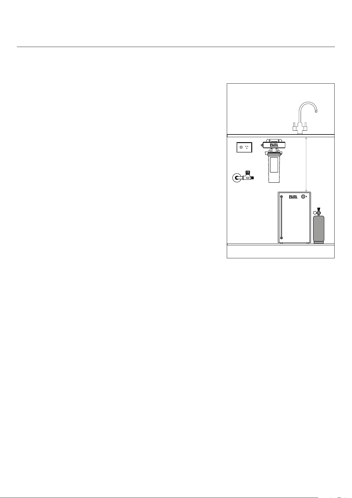
Alpine Sparkling Suggested Layout
Power
Outlet
Stop Tap
(Installed by Plumber)
Max 600mm from Unit
Cupboard Dimentions:
440mm Minimum Width
425mm Minimum Depth
800mm
Tube Length
Supplied
Diagram 1
Power Requirements
A single 10 amp GPO is required installed in
an accessible position. Refer to Diagram 1.
Power circuits must be fitted with an earth
leakage protection device (RCD). Chilled
water module is supplied with a 1 meter flex
cord and plug.
2
Page 3
Installation requirements.
Front
Back
Top
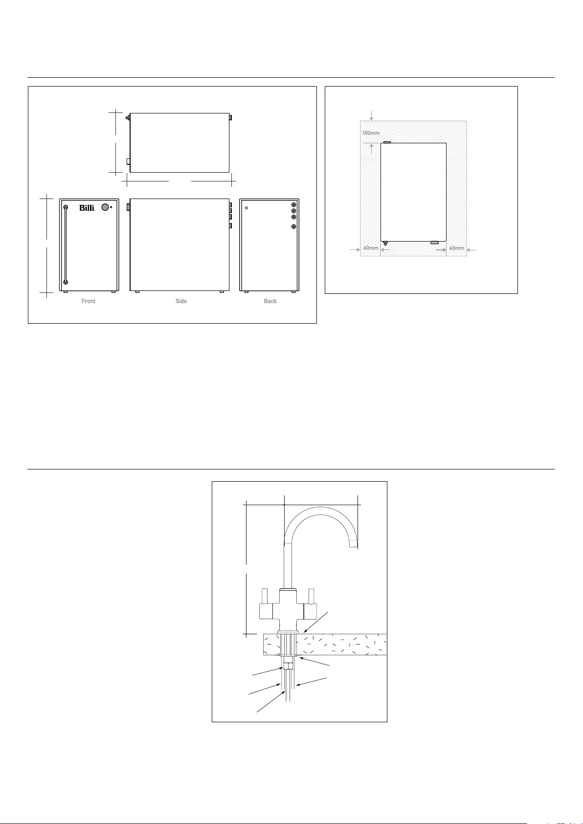
Chilled Water Module Dimentions
255mm
410mm
Alpine Sparkling Ventilation Clearances
420mm
Top
Note: Shaded area shows minimum ventilation clearance
Diagram 3
Diagram 2
Installing the dispenser.
Install Dispenser Assembly
Determine position of dispenser mounting
hole in sinktop or benchtop. Refer to
Diagram 4 for clearances allowed and correct
assembly. Hole size required is ø22mm.
Maximum benchtop thickness is 54mm.
1. Screw the threaded stud into base of
dispenser
2. Slide chrome mount base over tubes and
up to the bottom of the dispenser. Ensure
rubber sealing ring is at the bottom.
3. Feed dispenser tubing through the
mounting hole.
4. Fit the crescent shaped washer onto the
threaded shaft.
5. Fit retaining nut and hand tighten.
6. Check dispenser tubing is not pinched
and dispenser is correctly orientated.
7. Tighten retaining nut
Brass
locking nut
6mm blue
tube
Threaded
stud
290mm
157mm
22mm
Hole
bench
thickness
1mm-40mm
Crescent washer
6mm clear
tube
Diagram 4
3
Page 4

Installation schematic.
Flow control
fittings
Black tube Water supply
15mm stop
tap & PLV
FILTER MODULE
Blue - Still
Chilled
Black Water inlet
CO
REGULATOR
2
Clear - Sparkling
Chilled
Clear -
inlet
CO
2
Ice bank
fill tube
Clear
Blue
Black
Clear
Black
Fittings shown
with dotted lines
are at rear of
module
10A power point
BOTTLE
2
CHILLED WATER MODULECO
Diagram 5
4
Page 5

Installing underbench module.
Install Pressure limiting valve
a. Screw pressure limiting valve (PLV)
onto water supply tap using thread
sealant and PTFE plumbers tape.
b. Fit ¼-6mm fitting to outlet of PLV
Flush Water Supply
Flush water supply pipework before installing
the underbench unit by running water from
supply tap into a bucket. NOTE: Blockages/
unit malfunction caused by debris are not
covered by warranty.
Clearances for ventilation and service
Take care to observe minimum clearances.
Refer to Diagram 1 and 3. Ensure there
is adequate clearance for ventilation and
service access to the units taking into
consideration the tube lengths and space
available.
Tubing
Tube connections are made using push-fit
connectors. Trim tubes to correct length.
Tubes should be cleanly cut square using
a sharp knife or plastic tube cutter. Ensure
that tube ends are round and not flattened
or kinked, then push into connectors firmly
until properly seated. (To release, press the
collet ring in while gently pulling on the tube).
Minimizing the tube lengths will improve the
performance of the chilled and sparkling
water.
Connect tubing
a. Trim dispenser clear and blue tubes to
correct length by holding tubes against
outlet fittings at rear of chiller and
marking cutting point.
b. Fit 6mm stem elbows to ends of both
clear and blue tubes.
c. Tube elbow stems are inserted into
bulkhead fittings at rear of chiller. Refer
to diagram 5 and 7 for correct tube order
and colour coding.
d. Fit 6mm stem elbows to 2 x black and 1 x
clear tube found in installation kit.
e. Insert tube elbow stems into rear
bulkhead fittings. Refer to diagram 5 and
7 for correct tube order and colour
coding. Tip. It is easiest to fit these 3
tubes to chiller before unit is installed.
f. Connect black water inlet tube to filter
module OUTLET fitting.
g. Fit clear 6 mm tube to compression
fitting on CO₂ bottle regulator. Unscrew
compression nut and slide tube over
tapered fitting shank. Finger tighten
compression nut. Refer to diagram 6.
NOTE: At this stage, do not connect black feed
tube between the Water supply PLV and filter
module. This will be connected once ice bank
has been filled. Instead, connect the black ice
bank fill tube to the water supply PLV outlet
fitting. Refer to Diagram 5.
Diagram 6
Diagram 7
Install Filter Module
Filter module must be mounted upright on
either the side or the rear of the cabinet.
Ensure there is sufficient clearance for
changing the filter cartridge. Filter module is
fixed using 2 x 6g screws supplied.
Install Chilled Water Module
Position chiller module in cupboard area
observing ventilation clearance requirements.
Assemble CO₂ bottle and pressure regulator
a. Remove CO₂ bottle from packaging
box. Remove plastic cap from threaded
outlet of bottle.
b. Remove CO₂ pressure regulator from
packaging and check pressure control
knob is turned fully anticlockwise.
c. Holding the CO₂ bottle upright, screw
the pressure regulator onto outlet. A
small amount of CO
regulator has been tightened.
d. Decide location of CO₂ bottle in
cupboard space.
gas will escape until
2
5
Page 6

Commissioning.
Fill Chiller Module ice bank
a. Fit black ice bank fill tube from chiller into
water supply PLV fitting. Refer to Diagram 5
b. Turn on water supply tap slightly. After
about 15 seconds, water will show in the
bottom of the sight glass tube. Watch this
level rise as water is fed in.
c. Turn water tap off when water level reaches
the minimum fill marker. Refer to Diagram
8. If tank is overfilled, disconnect sight
glass elbow fitting from top bulkhead fitting
and swing tube downwards and drain
required amount of water. Water level in
this tank will rise a little later as an ice bank
forms.
d. Disconnect 6 mm black fill tube from PLV
outlet fitting. Fit black plastic cap supplied
in installation kit onto end of tube. Tuck
black tube behind modules for later use.
e. Connect remaining black 6 mm tube
from water supply PLV to INLET fitting of
filter module.
Turn on Water Supply
Ensure filter is securely locked back into place.
Turn on water supply tap and ensure that there
are no leaks.
Turn on Power Supply
Plug chiller module power lead into power point
and switch on. Ensure chiller power switch
located at the rear of unit is ON. Sparkling units
will begin filling automatically. See Diagram 9.
Turn on CO₂
a. CO₂ supply is turned on by tightening the
pressure adjusting knob clockwise. Set the
initial pressure to around 3 Bar.
b. Check CO₂ pipework and fittings for leakage
using soapy water bubble test.
Chiller set up
a. Ensure Chiller power lead is plugged into
power point and turned on
b. Ensure chiller module power switch located
at rear of module is turned on.
c. Press left chilled water lever on dispenser
and let the water run for approximately 1
minute to condition filter.
d. Press right sparkling water lever and run
for approximately 20 seconds.
e. Check all fitting connections for leakage.
Purging air from the CO₂ system
Air trapped in the soda tank is detrimental
to the production of sparkling water and full
carbonation may not be reached until 2-3 days
of use. To speed this process, it is beneficial
to purge the tank with CO₂ using the following
procedure:
a. Press RH tap levers and allow soda water to
flow.
b. Continue to run the tap until the tank is
empty and gas flows from the outlet. Soda
water feed pump will continue to run.
c. Release tap lever. Wait until soda water
pump stops. Some CO₂ gas may be
released from internal relief valve as soda
tank refills.
d. Press each lever in turn and check that
water flows.
Set Chilled Water Temperature
Set the desired water temperature using
temperature control knob. Refer to Billi Alpine
Sparking User Guide. Chiller refrigeration
system will run continuously for approximately
2 – 3 hours as ice is formed in the ice bank. As
a significant amount of heat is dispelled during
this time, it is advisable to leave a cupboard
door ajar during the initial cool down. As ice
expands, the water level in the ice bank tank
will rise slightly. Check water level is within
operating range on sight glass level markings.
Water level can be reduced if necessary. See
Diagram 8.
Adjusting carbonation level
It is advisable to wait for cold water
temperature to stabilize and air to be purged
from the sparkling water unit before adjusting
the carbonation level. Initial set point may vary
once the unit is running. A pressure between 3
and 4 Bar will typically provide the right level of
carbonization.
WARNING: Do not set the pressure to exceed
5 Bar
Re-check connections for leaks.
Explain operation to user.
Diagram 8
Diagram 9
6
Page 7

Commissioning
Checklist WARNINGS.
CHECK EACH OF THE FOLLOWING ITEMS:
Dispenser mounted securely.
Tubing cut to correct lengths and not
twisted or kinked.
Tubing secured correctly
Unit connected to COLD water supply.
Water main flushed before connection to
unit.
Correct air clearances around unit.
Power circuit fitted with an RCD
– earth leakage protection device.
Sawdust cleaned out of cupboard area.
Door vents and spacer pads fitted
correctly
Unit cooling (after initial fill).
Chilled and sparkling water flow correct.
If any difficulties arise contact
Australia Pty Ltd: Phone 1800 812 321
Billi
(Free call). Validate your warranty online at
www.billi.com.au
For information on our filtration
and service contracts please contact
Billi Customer Service on 1800 812 321
or service@billi.com.au.
For continued safety of this appliance it must be installed, operated and maintained in accordance
with the manufacturer’s instructions. For correct operation of this appliance, it is essential to
observe the instructions as outlined in this booklet.
— Your appliance should be installed by a suitably qualified tradesperson.
— For correct operation of this appliance it is essential to observe the instructions as outlined in this
booklet.
— Do not use this appliance with water that is microbiologically unsafe or with water of unknown
quality without adequate disinfection before or after the system. Systems certified for cyst
reduction may be used on disinfected water that may contain filterable cysts.
— Filter replacement must be performed at intervals of not more than 12 months.
— Use this appliance only as directed in these instructions and relevant Billi User Guide and only for
its designed purpose.
— Do not install unit if power cord is damaged.
—If the appliance has been turned upside down during transport and handling, wait at least
8 hours before switching appliance on.
— This appliance is not intended for use by persons (including children) with reduced physical,
sensory or mental capabilities, or lack of experience and knowledge, unless they have been given
supervision or instruction concerning use of the appliance by a person responsible for their safety.
Children should be supervised to ensure that they do not play with the appliance.
—This appliance is designed for indoor installation only and must not be exposed to direct
sunlight, rain and excessive heat, cold, damp or dust.
—Do not store solvents or corrosive chemicals or other flammable items on or around this
appliance
—DANGER: High Voltages. Power supply must be disconnected before cleaning or removing and
outer covers form the appliance. Any service or unit repairs must be performed by a trained
and suitably qualified technician.
— If the supply cord is damaged, it must be replaced by the manufacturer, its service agent or
similarly qualified persons in order to avoid a hazard.
— New hose-sets supplied with the appliance are to be used and old hose-sets should not be re-used.
—Packaging material including plastic bags must be kept out of reach of children and
disposed of according to local regulations.
Page 8

Billi Australi
42 Luckno
Victoria 3074 Australia
Telephone 1800 812 321
Facsimile +61 3 9469 0499
www.billi.com.au
a Pty Ltd
w Cr
escent, Thomastown
Designed and manufactured in Australia.
As Billi Australia Pty Ltd has a policy of
continual improvement, all details are
subject to change without notice. All
goods are sold subject to our published
terms and conditions. Billi is a registered
trademark. 0618
 Loading...