

Page 1
Installation guide
Billi B-5000 Sparkling
Tap option XL
Page 2
Installation requirements.
XL
Unpacking your Billi B-5000 Sparking Unit
Before commencing installation, carefully
check for any damage to outer carton, inner
liner, appliance metalwork, pipework fittings
and electrical power cord. If damage is found,
please photograph and record details for use
if a claim is to be made.
WARNINGS relating to this appliance must be
read before commencing installation. Refer
to page 8.
When unpacking your appliance, ensure you
have identified the following components:
1. Boiling water module
2. Chilled water module
cylinder
3. CO
2
regulator
CO
2
4. Dispenser
5. Tube spring clamps x 2
6. Natural and 2 x black Ø6 mm PE tubes
with stem elbows fitted
7. Extra 6mm stem elbow fitting
8. 600mm flexible braided hose
9. Filter cartridge (installed)
10. User guide
11. Warranty registration card
12. Warning label
13. Plastic Ø6mm tube cap
14. 5mm door spacer pads
15. Ventilation grille - cupboard base
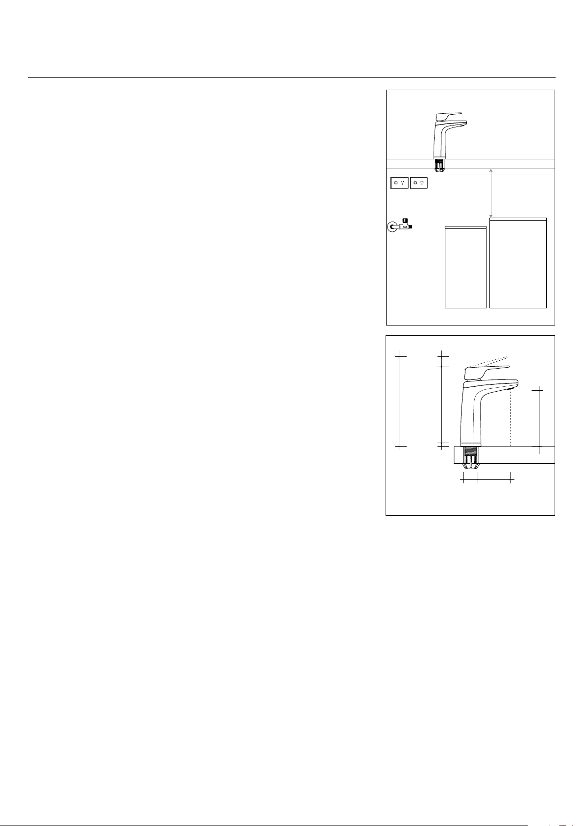
Determine Unit Location
Plan the installation carefully, taking into
consideration dispenser tube lengths,
position of power and water outlets,
ventilation airspace requirements and access
for service. Refer to diagrams 1, 2, 3a, 3b and
4. Diagram 4 shows minimum clearances
required around the units for ventilation
Water Supply
A single cold water supply point with a ½” BSP
stop tap is required. Stop tap is to be installed in
an easily accessible position, within 600 mm of
the inlet to the boiling water module. Sparkling
chilled water module is supplied from an outlet
fitting on the Boiling water module.
Dynamic supply pressure: Min. 250 kPa, max,
1000 kPa
Supply temp: Min. 5°C, max. 30°C
Power Requirements
B-5000 Sparkling requires 2 single or 1
double 10 amp GPO, installed in an accessible
position. Refer to Diagram 1. Power
circuits must be fitted with an earth leakage
protection device (RCD). Both boiling and
chilled water module are supplied with
a 1 meter flex cord and plug. Cupboard
ventilation fan kits require an extra 10A GPO
outlet.
Ventilation Grilles
A ventilation kit including lower cupboard
vent grille and 5mm door spacers is
supplied with each Billi Sparkling/Chilled
water unit.Separate installation instructions
are provided within the vent kit packaging.
For lower usage, domestic installations,
sufficient ventilation may be provided by
natural air movement through the cupboard
airspace. Minimum area of lower and upper
air vent openings is 100 cm²
Fan assisted vent kit
For units installed in higher usage or warm
climate areas, including office or commercial
installations, additional cupboard ventilation
should be provided. Billi provides a fan
assisted air circulating vent kit which
draws air in through the cupboard base in
front of the kickboard. Billi part no 990715
Installation instruction are provided with kit
packaging. Ventilation fan kits require an
extra 10A GPO outlet.
Stop Tap
(Installed by Plumber)
Max 600mm from Unit
20mm
175mm
205mm
10mm
bench
thickness
1mm-48mm
Tubing
removed
for clarity
Tubing
removed
for clarity
800mm
Tube Length
Supplied
60mm min
clearance
35mm 70mm
Diagram 1
130mm
Diagram 2
Do not install with water that is
microbiologically unsafe or with water of
unknown quality without adequate disinfection
before or after the system. Systems certified
for cyst reduction may be used on disinfected
water that may contain filterable cysts.
2
Page 3
Installation requirements.
XL
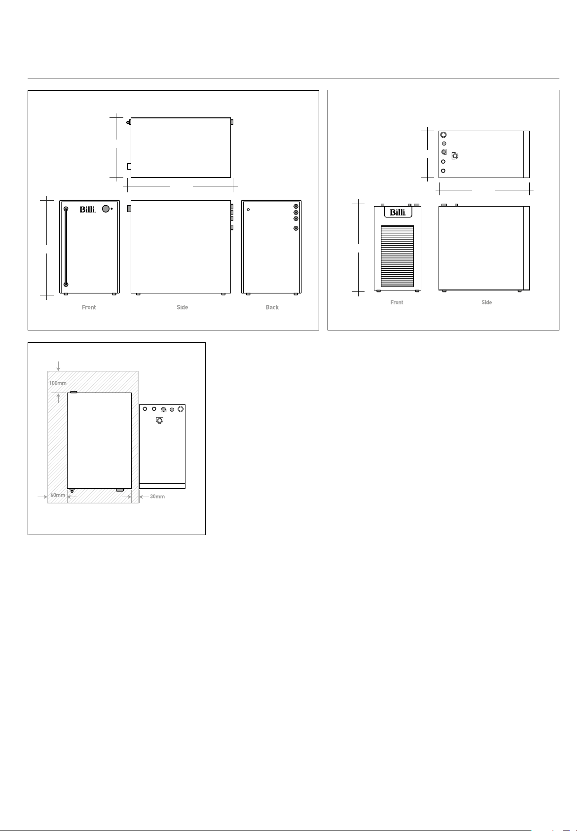
Chilled Water Module Dimentions
255mm
410mm
B-5000 Sparkling Suggested Layout
420mm
Diagram 3a
Boiling Water Module Dimentions
180mm
365mm
340mm
Diagram 3b
Note: Shaded area shows minimum ventilation clearance
Diagram 4
3
Page 4

Installing the dispenser.
XL
IMPORTANT: This Billi appliance is to be installed by a licensed trades person in accordance with
AS/NZS 3500.1 and AS/NZ 3500.2 and in compliance with applicable state regulatory requirements.
For correct operation of this appliance, it is essential to observe the manufacturer’s instructions.
1. Install Dispenser Assembly
Determine position of dispenser mounting
hole in sink top or bench top. Dispenser base
template (Diagram 5) may be cut out and
used to assist in correct positioning. Ref
er to
Diagram 2 for clearances allowed. Hole size
required is ø32mm.
The Billi XL dispenser is supplied with base
assembly preassembled into dispenser
upper and this must be first removed prior to
starting installation. Using allen key supplied
in installation kit, remove chrome plated
M4 screw from rear of housing. Twist base
casting around 60º and then slide assembly
out of upper housing. Carefully pull tubing
and electrical cable and plug through base
assembly.
—Stainless Steel Sinktop
A suitable 32mm hole punch (Part no:
857901) is available as an accessory from
Billi Australia Pty Ltd. If possible, cut hole
with die mounted below the sinktop surface
so that burr is pulled downwards.
Alternatively, remove burr and radius edge
of hole with fine file. This allows barbed
dispenser mount to slide smoothly into
mounting hole.
—Timber/Laminate Benchtop
Maximum benchtop thickness is 50mm. Cut
32mm hole in appropriate position. When
drilling through a particle board bench top,
take care to avoid substrate chipping and
breaking away as drill breaks through
underside surface. We recommend drilling a
small pilot hole through benchtop, partially
drilling the 32mm hole from underneath and
then completing drilling the hole from above.
The large 30mm washer supplied may be
used to secure barb where bench top
substrate has chipped away.
—Granite/Marble Benchtop
For granite or marble bench tops
we recommend that you use a certified
stone mason to pre-drill the hole.
2. Activate Dispenser Swivel Feature
The XL dispenser can be installed either as
locked into straight position or able to swivel
45º in either direction. To activate the swivel
feature of your dispenser, remove the
locking piece from the dispenser base.
Simply push out the piece as show in
Diagram 6. This will allow the tap to swivel to
the left and right.
3. Fit Dispenser Base
a. Cut a 32mm hole in sinktop or benchtop.
Remove burr if protruding upwards.
b. Push barbed mounting shaft through
mount hole.
c. Insert barb locking bush as shown in
Diagram 7. Finger tighten nut.
d. Ensure barb is centred in mount hole
before tightening. Check position of base
ring and gasket.
e. Moderately tighten locking nut using
multigrips or spanner. Take care to avoid
overtightening nut which may break the
plastic threaded shaft.
f. Place large D washer over thread as
shown in Diagram 7.
g. Cut off excess threaded shaft with a
hacksaw, using washer as a cutting guide.
(Diagram 8)
IMPORTANT: Remove burrs and check internal
bore is completely smooth.
4. Fit Dispenser Head Assembly
a. Feed dispenser tubing and loom through
center hole in the following order:
i. Dispenser power cord
ii. Silicone tubes
iii. Blue PE tube.
b. Gently pull hoses from under the bench
top. Do not attempt to force tubing through
with a pointed object as silicone tube is
easily punctured. Check tubing is not
kinked or twisted. Refer to Diagram 9.
c. Turn dispenser head assembly to
approximately 60° from the straight ahead
position of dispenser base. Slide head
assembly onto base assembly whilst
gently pulling tubing downwards from
underneath to prevent tubing bunching and
kinking. Head retaining lugs will pass nut
and slide down the 3 grooves on the swivel
bearing.
d. Once fully down, turn dispenser to
straight ahead position. Fit chrome
plated M4 retaining screw to lower rear
threaded hole and tighten using the allen
key supplied. If swivel feature is activated,
check dispenser now swivels smoothly 45°
in each direction.
dispenser base
Locking Nut
Base Casting
Ensure burr
is removed
& edge has
a radius
Barbed
Mounting
Shaft
Barb locking bush in position
Remove burrs after cutting and
ensure internal bore is smooth
Cut o
excess
thread
D washer
template
Diagram 5
Diagram 6
Swivel
Bearing
Gasket
D Washer
required
Diagram 7
Alloy locking
bush
Diagram 8
Silicone
tubing
Diagram 9
4
Page 5

Installing underbench module.
XL
1. Flush Water Supply
Flush water supply pipework before
installing the underbench unit by connecting
600mm flexible braided hose to the supply
tap and running water into a bucket. NOTE:
Blockages/unit malfunction caused by debris
are not covered by warranty.
Red silicone tube
Grey silicone tube
2. Install Underbench Unit
Take care to observe minimum clearances.
Refer to Diagram 1 and Diagram 4. Ensure
there is adequate clearance for ventilation and
service access to the units, considering the
tube lengths and space available.
3. Connect Dispenser Tubing and Plug
IMPORTANT: Boiling outlet (red), vent tube
(grey) must not be kinked and must be installed
with a continual fall and no sag.
Connect all tubing and electrical plug as
shown in Diagrams 10 and 11.
a. Trim silicon tubes to correct lengths using
a sharp knife or plastic tube cutter. Avoid
leaving excess tubing which will sag and
trap water. Fit spring clamps to tubing
prior to connecting.
b. Red silicone tube pushes on to boiling
module fitting labelled BOILING (RED).
Secure with spring clamp supplied.
c. Grey silicone tube pushes on to boiling
module fitting labelled VENT (GREY)
Secure with spring clamp supplied.
d. Dispenser electrical cable Mini-Din
connector plugs into boiling unit socket.
e. 6mm PE tube connections are made
using push-fit connectors. There are
3 x Ø6mm tubes supplied loose in your
installation kit; 2 x black, and 1 x natural
(clear). Each tube has an elbow fitting
attached to one end. An additional 6mm
elbow is supplied which is to be fitted to
the blue dispenser tube once tube has
been trimmed to correct length.
f. Tube elbows are inserted into fittings at
rear of chiller. Refer to diagram 10 and
11 for correct tube orientation and colour
coding.
Tip. It is easiest to fit these tubes to chiller
before unit is installed. Before inserting
tubing into push-fit connectors, ensure
that tube ends are cleanly cut and not
flattened or kinked. Tube is pushed
firmly into connector until properly
seated. (To release, press the retaining
collet ring inwards while pulling gently on
the tube).
g. Connect power lead with 6-way mini din
plug from boiling module to socket
located at rear RHS of the sparkling water
module -refer to diagram 12. Rear
mounted plug guide bracket helps to
locate socket position and orientate plug
correctly.
Top view of
Boiling module
connection fittings
10A power point
Dotted lines
show ice bank
filling pipe which
is connected to
Ambient Outlet
fitting while ice
bank is being
filled.
BOILING WATER MODULE CHILLED WATER MODULECO
15mm stop
tap
2
NOTE: At this stage, do not connect CLEAR
feed tube between boiling and chilled water
modules. This will be connected once ice bank
had been filled. Instead, connect the BLACK
tube to the ambient water fitting on the
boiling module. Refer to diagram 10.
4. Connect CO
regulator
bottle and pressure
2
a. Remove CO2 bottle from packaging box.
Remove plastic cap from threaded outlet
of bottle.
b. Remove CO
packaging and check pressure control
pressure regulator from
2
knob is turned fully anticlockwise.
c. Holding the CO
the pressure regulator onto outlet. A
small amount of CO
regulator has been tightened.
d. Decide location of CO
space.
bottle upright, screw
2
gas will escape until
2
bottle in cupboard
2
e. Black Ø6 mm tube from chiller module
connects to outlet of gas regulator. Trim
tube to correct length, push into fitting
and tighten retaining nut. Refer to
Diagram 10 & 13.
BOTTLE
Connecting cable
Blue
Tube
Clear tube
Black tube
Black tube
Fittings shown
with dotted lines
are at rear of
module
10A power point
Diagram 10
Diagram 11
Diagram 12
Diagram 13
5
Page 6

Commissioning
XL
Turn on Water Supply
Remove boiling module front panel. Remove
foam packing piece from under filter canister.
Ensure filter is securely locked back into
place. Turn on water supply tap and ensure
that there are no leaks.
Turn on power to boiling and chilled modules
Plug both boiling module power lead and
chiller module power lead into power points
and switch on. Ensure chiller power switch
located at the rear of unit is ON (Diagram 14).
Boiling and Sparkling units will begin filling
automatically.
Fill Sparkling Chiller Module ice bank
a. Fit black ice bank fill tube from chiller into
‘AMBIENT OUTLET’ fitting on Boiling
Module. Refer to Diagram 10.
b. Lift cold water lever on dispenser tap.
After about 15 seconds, water will show
in the bottom of the sight glass tube.
Watch this level rise as water is fed in.
Note: If ambient water flow stops before
ice bank is full, release cold lever and lift
again. If FILL FAULT light shows, turn
power switch at rear of chiller off and on.
c. Release cold lever when water level
reaches the minimum fill marker. Refer to
Diagram 15. If tank is overfilled,
disconnect sight glass elbow fitting
from top bulkhead fitting and swing tube
downwards and drain required amount of
water. Water level in this tank will rise a
little later as an ice bank forms.
d. Disconnect Ø6 mm black fill tube from
boiling module ambient water outlet
fitting. Fit cap supplied in installation
kit onto end of tube. Tuck black tube
behind modules for later use.
e. Connect clear Ø6 mm tube from chiller
module to the boiling module fitting
labeled ‘AMBIENT OUTLET’.
Boiling water temperature calibration
Boiling water module will begin to heat after
water level in the tank reaches the lower
level sensor. The unit will also automatically
begin a temperature calibration cycle. During
the calibration cycle, hot water temperature
continues to rise until it begins to boil. Once
water is boiling, the temperature does not
rise any further as all electrical energy is
converted to steam. The unit will continue
to boil for up to 30 seconds while the
temperature sensor calibrates.
WARNING: Steam and small amount of hot
water may be discharged from the taps and
vent during this period. While calibration cycle
is operating, the hot water indicator (red) will
double blink rapidly.
Once calibration cycle is completed, the unit will
resume normal operations and the calibration
data is saved.
Chiller set up
a. Ensure Chiller power lead is plugged into
power point and turned on
b. Ensure chiller module power switch located
at rear of module is turned on.
c. Lift chilled lever on dispenser and let the
water run until it stops automatically. (60s)
d. Return the chilled lever to the center
position.
e. Lift both levers up together and hold for
about 20 seconds. Water should run from
the dispenser.
f. Release the levers and check for leaks
Set up CO₂ system
a. Screw CO
hand tighten. Some gas may escape during
this process.
b. Open the CO
knob clockwise (diagram 12)
c. Set the initial pressure to around 3 Bar.
d. Press both tap levers and dispense water
and ensure the gas pressure stabilizes.
NOTE: Water carbonation levels will
continue to increase until water in the soda
canister has become chilled and air has
been dispelled.
Purging air from the CO₂ system
Air trapped in the soda tank is detrimental
to the production of sparkling water and full
carbonation may not be reached until 2-3 days
of use. To speed this process, it is beneficial
to purge the tank with CO
procedure:
a. Lift both tap levers and allow soda water to
flow.
b. Continue to run the tap until the tank is
empty and gas flows from the outlet. Soda
water feed pump will continue to run.
c. Release tap levers. Wait until soda water
pump stops. Press both tap levers together
and check that water flows.
d. Press cold lever only and check that water
flows.
Set Chilled Water Temperature
Set the desired water temperature using
temperature control knob. Refer to Billi B-5000
Sparking User Guide. Chiller refrigeration
system will run continuously for approximately
2 – 3 hours as ice is formed in the ice bank. As
a significant amount of heat is dispelled during
this time, it is advisable to leave a cupboard
door ajar during the initial cool down. As ice
expands, the water level in the ice bank tank
will rise slightly. Check water level is within
operating range on sight glass level markings.
Water level can be reduced if necessary. See
Diagram 15.
NOTE: To drain water from ice tank, disconnect
upper sight-glass fitting, swing tube downwards
and drain water into a cup or container.
cylinder into CO2 regulator and
2
regulator by turning the black
2
using the following
2
Adjusting carbonation level
It is advisable to wait for cold water
temperature to stabilize and air to be purged
from the sparkling water unit before adjusting
the carbonation level. Initial set point may vary
once the unit is running. You may need to adjust
the pressure once the system has stabilized.
A pressure between 3 and 4 Bar will typically
provide the right level of carbonization.
WARNING: CO
Re-check connections for leaks.
Explain operation to user.
pressure must not exceed 5 bar
2
Diagram 14
Diagram 15
IMPORTANT: Do not turn power off to boiling
water unit until calibration cycle has finished.
6
Page 7

Commissioning
Checklist
CHECK EACH OF THE FOLLOWING ITEMS:
Filter packing foam removed
from under filter cannister.
Dispenser mounted securely – M4
chrome retaining screw fitted.
Dispenser swivels 45º in each direction
(if activated) - locking piece is removed.
Tubing is cut to correct lengths and
not kinked or sagging. Red and grey
silicone tubes have a continual fall.
Tubing secured correctly – nuts and
spring clips fitted.
Water main flushed before connection to
unit.
Unit connected to COLD water supply.
Correct air clearances around unit.
Power circuit fitted with an RCD
– earth leakage protection device.
Sawdust cleaned out of cupboard area.
Door vents and spacer pads fitted
correctly
Initial program settings correctly set
for dispenser tube length.
Unit heating and cooling (after initial fill).
Red and blue dispenser icons flashing
(or on continually when reached correct
temperature).
Boiling and chilled water flow correct.
If any difficulties arise contact
Australia Pty Ltd: Phone 1800 812 321
Billi
(Free call). Validate your warranty online at
www.billi.com.au
For information on our filtration
and service contracts please contact
Billi Customer Service on 1800 812 321
or service@billi.com.au.
WARNINGS.
For continued safety of this appliance it must be installed, operated and maintained in
accordance with the manufacturer’s instructions. For correct operation of this appliance,
it is essential to observe the instructions as outlined in this booklet.
— Your appliance should be installed by a suitably qualified tradesperson.
— For correct operation of this appliance it is essential to observe the instructions as
outlined in this booklet.
— Do not use this appliance with water that is microbiologically unsafe or with water of
unknown quality without adequate disinfection before or after the system. Systems
certified for cyst reduction may be used on disinfected water that may contain filterable
cysts.
— Filter replacement must be performed at intervals of not more than 12 months.
— Use this appliance only as directed in these instructions and relevant Billi User Guide and
only for its designed purpose.
—Do not install unit if power cord is damaged.
— This appliance is not intended for use by persons (including children) with reduced
physical, sensory or mental capabilities, or lack of experience and knowledge, unless
they have been given supervision or instruction concerning use of the appliance by a
person responsible for their safety.
—Always activate boiling water safety lock switch where children or mentally disabled
persons could access the appliance.
—This appliance is designed for indoor installation only and must not be exposed to
direct sunlight, rain and excessive heat, cold, damp or dust.
—Do not store solvents or corrosive chemicals or other flammable items on or around
this appliance
—DANGER: High Voltages. Power supply must be disconnected before cleaning or
removing and outer covers form the appliance. Any service or unit repairs must be
performed by a trained and suitably qualified technician.
— Children should be supervised to ensure that they do not play with the appliance.
— DANGER: The operation of the thermal cut-out indicates a possibly dangerous situation.
Do not reset the thermal cut-out until the water heater has been serviced by a qualified
person.
— WARNING: Do not connect any restrictor or pressure relief device to the vent pipe of this
water heater if installed.
— If the supply cord is damaged, it must be replaced by the manufacturer, its service agent
or similarly qualified persons in order to avoid a hazard.
— New hose-sets supplied with the appliance are to be used and old hose-sets should not
be re-used.
—Packaging material including plastic bags must be kept out of reach of children and
disposed of according to local regulations.
—If the appliance has been turned upside down during transport and handling, wait for
at least 8 hours before switching appliance on.
7
Page 8

Billi Australi
42 Luckno
Victoria 3074 Australia
Telephone 1800 812 321
Facsimile +61 3 9469 0499
www.billi.com.au
a Pty Ltd
w Cr
escent, Thomastown
Designed and manufactured in Australia.
As Billi Australia Pty Ltd has a policy of
continual improvement, all details are
subject to change without notice. All
goods are sold subject to our published
terms and conditions. Billi is a registered
trademark. 0618
 Loading...