

Page 1

Operating manual
Page 2
Page 3
Page 4
Info
Mode
Hi
Lo
Power
Page 5
EF
POWER
STANDARD
AV
km/h
km/h
5
3
Power
Assist
Mode
2 sec.
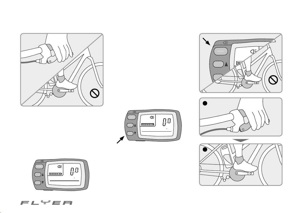
6. If you have a FLYER with an LCD control
panel, press the “Power” button.
Ensure that you do not place your feet on the
pedals while switching the motor on or during
the two seconds subsequent to this.
The strength of the motor support is regulated
here by pressing both the “Assist” buttons. If
you would like stronger support, press the upper of the two buttons, with the arrow pointing upwards/forwards. By pressing the lower
“Assist” button, the support is reduced. Every
time you press one of these buttons, the level
of support changes by one step.
2 sec.
1
5. After switching on, the middle level of
support is always turned on. By pressing the
“Mode” button, you can set how strong the motor support should be. Every push of the button
switches the support one lever higher. When
the highest possible support has been reached,
pressing the “Mode” button again switches
back to the weakest level of support.
POWER
km/h
3
5
km/h
AV
Power
EF
Assist
STANDARD
Mode
POWER
Power
Assist
EF
STANDARD
Mode
km/h
3
5
km/h
AV
7. Apply at least one of the brakes before
placing your feet on the pedals. As soon as you
start to pedal, the motor will start supporting
you. This is helpful in getting going and on uphill routes, but this can also lead to uncertainty
and serious falls when it is unfamiliar.
2
Now you can start riding!
Page 6
2
Declaration of conformity
IV. Declaration of conformity
EC Declaration of conformity 2012
(Only applicable to models requiring registration)
The manufacturer Biketec AG
Schwende 1
CH-4950 Huttwil
Switzerland
Telephone +41(0)62 959 55 55
hereby declares that the following products:
Product name: FLYER Pedelec
Type names: C series, T series, L series, S series, R series, K series, X series, ISY, Cargo, Folding bike, Tandem
Year of manufacture: 2011 / 2012
are in accordance with all applicable provisions from the guideline Machinery (2006/42/EC).
The products are also in accordance with all provisions from the guideline
Electromagnetic compatibility (2004/108/EC)
and Low voltage directive (2006/95/EC) (charger only).
The following harmonised norms were applied:
DIN EN 15194 Cycles - Electrically power assisted cycles - EPAC Bicycles
DIN EN 14764 City and trekking bicycles - Safety requirements and test methods
Technical documentation is available from:
Biketec AG
Hans Furrer
Schwende 1
CH-4950 Huttwil
Switzerland
Huttwil, december 2011
On behalf of Biketec AG:
Kurt Schär Hans Furrer
Managing director Head of product management and production
Page 7
1. Foreword
3
Dear FLYER Customer,
In order to familiarise yourself with your
new FLYER, it is essential to read this operating manual thoroughly before using it. The
manual includes many important pointers and
rules which should always be observed and
which inform you about various aspects of the
bike such as its technology, intended usage
and operation.
Info
This operating manual contains a brief introduction at the very start. If you already have
sufficient experience with pedelecs and ebikes, this brief introduction provides you with
enough information to ride the FLYER. However, to use the bike safely you have to read the
entire operating manual! This is the only way to
make the most of your FLYER safely and without any danger.
This operating manual assumes that you
and all other users of this FLYER have sufficient basic knowledge of using bicycles and
pedelecs. If you feel unsure about any aspects
of the bike or if important work has to be carried out on your FLYER, always consult your
specialist retailer.
The contents of this manual and its importance should not only be known and completely
understood by you personally, but also by all
other people who use, clean, service, repair or
dispose of this FLYER!
The same applies here: If you do not understand something or have any additional
questions, please do not hesitate to contact
your specialist retailer in the interests of your
own safety.
The topics addressed in this operating
manual relate to this vehicle – they address
the technology used on this FLYER, its design
as well as its care and maintenance. Observing
the information stated in this manual can have
great consequences for your own safety, while
by the same token disregarding it can result in
serious accidents as well as financial damages.
In addition to the information specific to this
FLYER, you also have to inform yourself of all
the rules and laws applicable on public roads
– these can differ depending on your country
of residence.
Page 8
4
Overveiw of content
2. Overview of content
I. Safety information – C2
II. The pedelec and its parts – C3
III. Brief introduction – C4 f.
IV. Declaration of conformity – 2
V. Operating instructions / manual – 3
1. Foreword – 3
2. Overview of content – 4
3. Legal regulations – 6
3.1 Switzerland – 6
3.2 Germany – 7
3.3 Austria – 8
4. Intended use – 9
5. Before the first ride – 10
6. Before every ride – 11
7. Adjusting the bike to the rider – 12
7.1 Setting up the seating position – 12
7.2 Operating quick releases – 13
7.3 Seat height – 14
7.4 Seat position – 15
7.5 Height of the handlebars – 16
7.6 Ahead stem – 17
7.7 Height of the handlebars on a folding
bike – 17
8. The battery – 18
8.1 Recharging the battery – 18
8.1.1 Removing the battery – 18
8.1.2 Charging the battery – 19
8.2 Re-fitting the battery – 20
8.3 Battery management – 20
8.4 Storage – 20
8.5 Checking the charge level – 21
8.5.1 Checking the battery capacity – 22
8.6 Life span and warranty of the battery – 22
8.6.1 Battery wear – 22
9. The charger – 23
10. The display panel – 24
10.1 LED display panel unlit – 24
10.2 LCD screen – 26
10.2.1 Measurement and display ranges – 28
10.2.2 Battery charge level display – 30
10.2.3 Energy consumption display – 30
10.3 Large LCD screen – 30
10.3.1 Operating the large LCD screen – 31
11. The electrical motor – 33
12. Frame – 34
13. Headset – 34
14. Fork – 35
15. Suspension frames and suspensionrelated parts – 35
15.1 Folding instructions for the FLYER
Folding bike – 38
16. Bottom bracket and cranks – 40
17. Checking the bottom bracket – 40
18. Wheels – 41
18.1 Checking the wheels – 41
18.2 Checking the hubs – 41
18.3 Checking the rims – 41
19. Tyres and inner tubes – 42
19.1 Tyres – 42
19.2 Inner tubes – 43
20. Dealing with a flat tyre – 43
20.1 Opening a brake – 44
20.1.1 Opening a V-brake – 44
20.1.2 Opening hydraulic rim brakes – 44
20.1.3 Loosening hub gears, roller or backpedal brakes – 44
20.2 Removing a wheel – 44
20.2.1 Removing the front wheel – 44
20.2.2 Removing the rear wheel – 45
20.3 Removing the tyre and inner tube – 46
20.4 Patching an inner tube – 46
20.5 Fitting a tyre and inner tube – 47
20.6 Fitting the wheels – 47
20.6.1 Fitting the front wheel – 47
20.6.2 Fitting the rear wheel – 48
20.6.2.1 FLYER with chain gears – 48
20.6.2.2 FLYER with hub gears – 48
21. Bicycle gears – 51
21.1 Chain gears – 51
21.1.1 Operating the gears – 52
21.1.1.1 Gear shift lever – 52
21.1.1.2 Gear grip shift – 52
21.1.1.3 Gear settings for chain gears – 52
21.2 Hub gears – 54
21.2.1 Operating hub gears – 54
21.2.1.1 Shimano 7/8 gear grip shift
(Nexus/Alfine) – 54
21.2.1.2 Shift lever 8/11 gear (Alfine) – 54
21.2.2 Setting up Shimano hub gears – 55
22. Bicycle chain – 56
22.1 Bicycle chain maintenance – 56
22.2 Tensioning a tandem chain! – 57
23. Brakes, brake levers and braking
systems – 58
23.1 Important information and precau-
tionary measures – 58
23.2 Brake levers – 59
Page 9
5
23.2.1 Standard brake levers – 59
23.3 Hub brakes – 60
23.3.1 Roller brakes – 60
23.4 Rim brakes (V-brakes) – 61
23.4.1 Adjusting brakes – 61
23.4.2 Setting the distance of the brake pad
to the rim – 61
23.4.3 Brake pad wear – 62
23.4.4 Hydraulic rim brakes – 62
23.5 Disc brakes – 63
23.5.1 Hydraulic disc brakes – 63
23.5.2 Formation of vapour bubbles – 64
23.5.3 Cleaning the brakes – 64
23.5.4 Fitting/removing wheels – 65
24. Lighting systems – 65
24.1 Lighting system regulations – 65
24.2 Dynamo – 66
24.2.1 Hub dynamo – 66
24.3 Failure of the lighting system – 66
25. Additional parts – 67
25.1 Luggage rack – 67
25.1.1 Front wheel rack – 68
25.1.2 Rear luggage rack – 68
25.2 Mudguard – 68
25.2.1 Re-locking a safety release – 69
26. Accessories and equipment – 69
26.1 Child seat – 69
26.2 Kickstand – 71
26.3 Bike trailer – 71
26.4 Basket – 71
26.5 Bar ends – 72
27. Car roof rack and rear carrier – 72
28. Carbon components – 73
28.1 Properties – 73
28.2 Torques – 73
28.3 Visual checks – 73
28.4 Carbon frame – 73
28.5 Danger of injury from splinters – 74
28.6 Attaching to assembly stands – 74
28.7 Car transport – 74
29. Servicing and caring for your pedelec – 74
29.1 Care – 74
29.2 Parts subject to wear – 75
29.3 Tyres – 75
29.4 Rims in connection with rim brakes – 75
29.5 Brake pads – 75
29.6 Brake discs – 76
29.7 Bicycle chain or drive belt – 76
29.8 Chain wheels, sprockets and jockey
wheels – 76
29.9 Lighting elements in the lighting
system – 76
29.10 Handlebar grips – 76
29.11 Hydraulic oils and lubricants – 76
29.12 Gear and brake cables – 76
29.13 Paintwork – 76
29.14 Bearings – 76
29.15 Plain bearings and bearings in fullsuspension frames, suspension forks
and other suspension parts – 77
30. Regular inspections – 77
30.1 Inspection plan – 77
30.1.1 Servicing/checks – 77
31. List of links – 79
32. Exchanging components on the “Speed
FLYER” – 79
32.1 Parts which may only be replaced with
approved parts – 79
32.2 Replacement tyres – 79
32.3 Components which do not have to
be replaced with approved replacements – 80
33. Technical information – 81
33.1 Permitted overall weight – 81
33.2 Permitted load of the luggage rack – 81
33.3 Torques for screwed connections – 81
33.3.1 General torques for screwed con-
nections – 82
33.4 Tyres and tyre pressure – 83
33.5 Lighting system – 83
34. Warranty and
guarantee conditions – 85
34.1 Prerequisites for a warranty or guarantee claim – 85
34.2 Exclusions from warranty and guarantee – 85
VI. Handover documentation – C5
VII. Bicycle pass – C6
Page 10
6
Legal regulations
3. Legal regulations
The regulations governing public road use and
approval for pedelecs vary from country to
country and are occasionally revised. Please
inform yourself of the currently applicable
regulations in your respective country. At the
time of printing this operating manual, the following regulations applied in Switzerland, Germany and Austria. Biketec AG does not accept
any responsibility for the up-to-dateness and
correctness of this information:
CH
3.1 Switzerland
Bicycles with electrical pedal support up to
a maximum speed of 25 km/h, a maximum
rated output of 0.5 kW and type-dependent top
speed of 20 km/h fall into the category of light
motor-assisted bikes. Bicycles with stronger
(-1000W) or faster (-45km/h) electrical pedal
support count as motor-assisted bikes and
require registration (number plate, driving license cat. M from the age of 14, certificate of
registration).
Driver’s licence
In general, a minimum age limit of 14 years
old applies for so-called light motor-assisted
bicycles. 14 to 16 year olds require a category
M driver’s licence, while a driver’s licence is no
longer required from the age of 16.
There is also a minimum age of 14 years
old for riding other motor-assisted bicycles.
Irrespective of this, a driver’s license (at least
category M) is required.
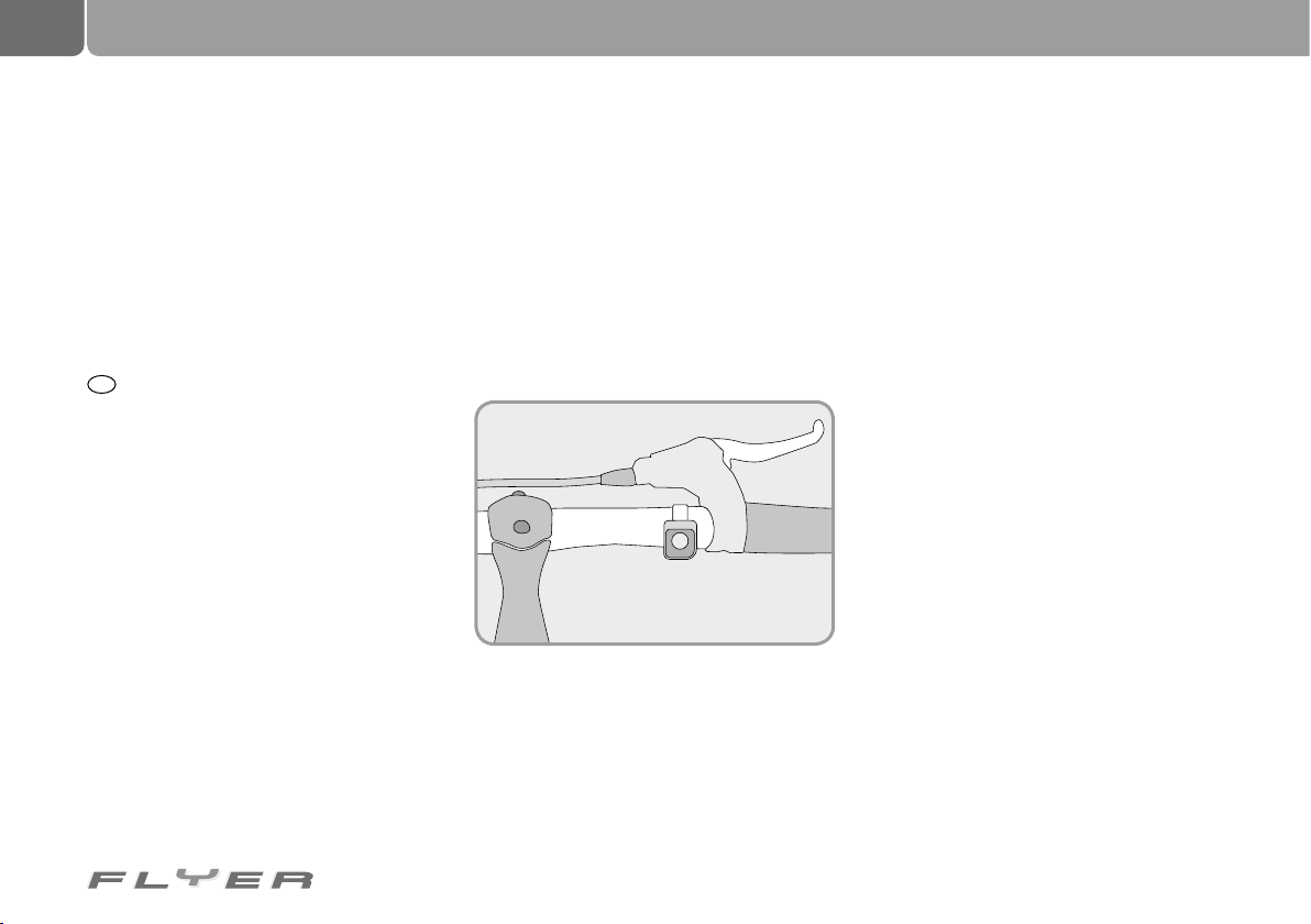
The pushing aid
A so-called pushing aid is installed in some
models.
This is capable of propelling your pedelec
slowly up to a maximum of 6 km/h or 20 km/h,
without you having to turn the pedals. If you have
to e.g. push the bicycle out of an underpass or a
parking garage, this aid can be helpful.
Using cycle paths and “Mofa-Verbot” routes
The “Radweg” sign obligates the riders of normal two-wheel bicycles, light motor-assisted
bicycles and motor-assisted bicycles to use
the marked path. “Mofa-Verbot” (moped-free)
represents paths and roads on which light motor-assisted bicycles and motor-assisted bicycles can always ride with a maximum speed of
20 km/h or 25 km/h with pedal support. These
paths can only be ridden by other motor-assisted bicycles with the motor switched off.
Mandatory helmet regulation:
There is no obligation to wear a helmet for riders of light motor-assisted bicycles and motorassisted bicycles which can ride with a maximum speed of 20 km/h or 25 km/h with pedal
support depending on the model.
A certified bicycle helmet pursuant to norm
EN 10782 is required to ride motor-assisted bicycles with a model-dependent top speed of 20
km/h and of up to 45 km/h with pedal support.
A moped helmet has to be worn by riders
whose motor-assisted bicycle can, depending
on the model, drive quicker than 20 km/h.
In your own interests and for your own safety, you should however always wear a helmet.
Page 11
D
3.2 Germany
The pedelec and the applicable legal principles (Germany)
Your FLYER pedelec supports you with up to
250 watts up to a maximum speed of 25 km/h.
The bicycle has to correspond with the
provisions of the StVZO (German Road Traffic
Regulations).
For more on this, please read the explanations as well as the general information in the
general operating manual.
In the following, the legal regulations for a
pedelec are described.
• The motor may only serve as support when
the rider is pedalling, i.e. it can only “help”
when the rider is pedalling himself or herself.
• The motor capacity may not exceed an average of 250 watts.
• The more the speed increases, the further
the motor capacity has to reduce.
• At 25 km (+/- 10 %) the motor support has
to switch itself off.
Driver’s licence and permission
• You are not legally required to wear a helmet.
In your own interests and for your own safety,
you should however always wear a helmet.
• You are not legally required to hold a driver’s license.
• You are not legally required to hold insurance.
• The regulations for using cycle paths are
the same as for normal bikes.
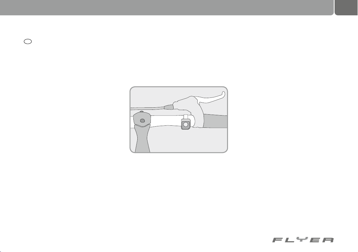
The pushing aid
A so-called pushing aid is installed in some
models.
This is capable of propelling your pedelec
slowly up to a maximum of 6 km/h, without you
having to turn the pedals, e.g. in order to push the
pedelec out of an underpass or up a steep ramp.
If you were born after 1.4.1965, you require a
moped test certificate for using a pedelec with
a pushing aid.
If you already hold a different driver’s license, this is also automatically valid as a moped test certificate.
A pedelec with a pushing aid is a pedelec
within the purpose described above, but also
encompasses other specific features: Using
a button, you can be supported up to 6 km/h
from a standing start with the pushing aid. The
legal provisions are largely the same as with a
7
normal pedelec. However, from a legal point of
view, this no longer counts as a bicycle but as
a motor vehicle with exceptional rules. That is
why the use of cycle paths is not regulated in
the same way as with the speed pedelec (for
more on this read chapter 3).
Please do not use the pushing aid to start
riding, as it is not suitable for this purpose.
Speed pedelecs and the applicable legal
principles in Germany
A speed pedelec supports you with up to 500
watts of continuous rated capacity up to a maximum speed of 45 km/h.
• Legally, your speed pedelec is a small motorised bike (with low capacity) of the class
L1e
• and it therefore has to adhere to the provisions of the StVZO.
For more on this, please read the explanations
as well as the general information in the general operating manual.
If the speed pedelec is only ridden using mo-
tor support, it may travel no faster than 20 km/h.
To achieve a speed of 45 km/h, it requires a combination of motor support and pedal power.
No child trailers which are transporting
children may be pulled.
For the rider, this means:
• There is no obligation to wear a helmet. In
your own interests and for your own safety,
you should however always wear a helmet.
Page 12
8
Legal regulations
• You are legally required to hold a driver’s
license. This should be a moped licence according to the regulations.
• However, if you own a German driver’s
licence, a moped licence is already covered by this.
• If you were born before 1.4.1965, you are
also permitted to ride a Speed FLYER without a driver‘s license.
• You are legally required to hold insurance
for your speed pedelec.
• Your use of cycle paths is restricted.
Speed pedelecs and the use of cycle tracks
Even if you use your speed pedelec or pedelec
with pushing aid like a bicycle, i.e. without the
support of the electrical motor, you are generally not permitted to use cycle paths within
urban areas unless there is a specific sign approving this (“Mofas frei”).
Outside urban areas, you may generally ride
your speed pedelec on cycle paths, unless it is
not permitted by specific signs (“Keine Mofas”).
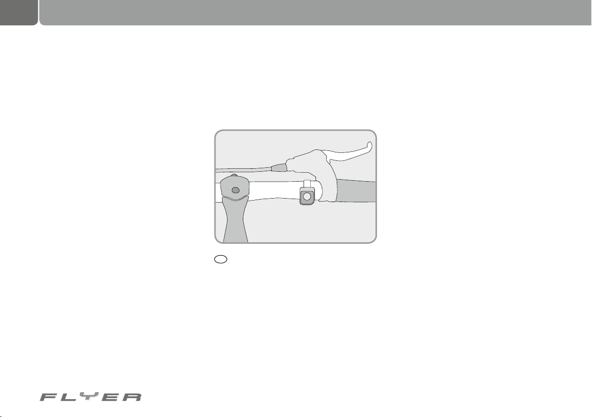
The start aid
Your Speed FLYER is also equipped with a start
aid. This enables you to ride purely using motor
power. You can therefore drive without having
to turn the pedals. This covers a range up to a
maximum speed of 20 km/h.
A
3.3 Austria
The pedelec and the applicable legal principles (Austria)
In Austria, electrically-powered bicycles with:
1. a highest permissible capacity not exceeding 600 watts and
2. a model-dependent speed of a maximum of
25 km/h
does not apply as a motor vehicle but as a
bicycle.
Legally, no differentiation is made between
pedelecs which only have the motor turned on
while turning the pedals and e-bikes, which do
not necessarily require pedalling.
A pedelec has to be used in cycle lanes, unless it has more than two wheels and is up to
80 cm wide or is pulling a trailer up to 80 cm
wide. Then you also have the choice of driving
on the road outside of the cycle lane.
Driver’s licence and permission
• No driver’s license is required.
• Minimum age, from which you can drive
without accompaniment: 12 years old, un-
less you have acquired a children’s bicycle
license.
• The same equipment regulations apply as
for conventional bicycles.
The pushing aid
A so-called pushing aid is installed in some
models.
This is capable of propelling your pedelec
slowly up to a maximum of 6 km/h, without you
having to turn the pedals.
The speed pedelec and the applicable legal
principles (Austria)
To operate a speed pedelec in Austria, please
inform yourself about the current applicable
legislation.
Page 13
4. Intended use
9
The term “intended use” is used to specify the
type of use intended for your FLYER as well
as the adherence to operating, servicing and
maintenance conditions, which are included in
this operating manual. The operating manuals of the individual component manufacturers
which are enclosed with this manual or which
are placed online, also have to be adhered to.
If you have any questions, please contact your
specialist retailer.
The FLYER is intended for
transporting one individual per-
son. Carrying a second person
is only allowed within the framework
of the respectively applicable national
legislation (children in a child seat or
trailers designed for this purpose, on a
tandem).
Permitted overall weight: Rid-
er‘s weight + FLYER weight +
weight of luggage/trailer
Carrying luggage is only permitted with appropriate equipment fitted on the FLYER. In this
context, the highest load of the luggage rack as
well as the highest permissible overall weight
may not be exceeded (see chapter 33 “Technical information”).
The FLYER is also subject to specific restrictions in its use. The vehicle is not permitted for extreme usage, e.g. jumps or riding
down stairs. Bicycles which are not specifically
permitted to compete in competitions may not
enter any competitions.
The information provided in this operating
manual applies for all FLYERs. If individual
models deviate from the information provided,
special note is made of this.
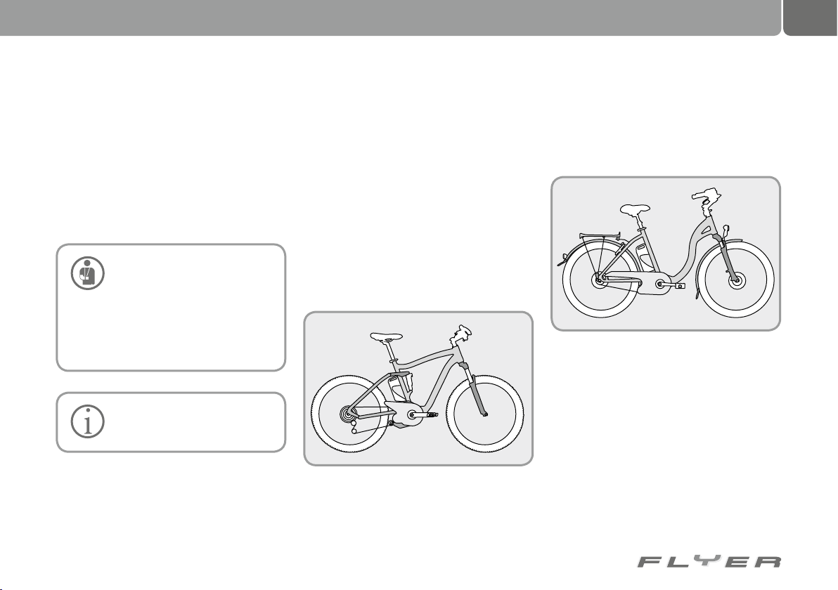
The following applies for hybrid bikes or the
X series FLYER:
They can be used on paved surfaces, but only in
public traffic if they are suitably equipped. They
are also suitable for use on country tracks or in
light off-road conditions.
For city and touring bikes, as well as all
other FLYER models, as long as they are
equipped according to the regulations of the
respectively applicable traffic legislation, the
following applies:
FLYERs are designed for use in public road
traffic and on paved surfaces.
All liability and warranty on the part of the
retailer and manufacturer is nullified if any
use above and beyond this intended use takes
place, if safety information is not observed, if
the bicycle is subject to excess load or if damage is not properly repaired. The guidelines for
servicing and care also have to be observed to
ensure liability and warranty remain intact.
Page 14
10
Before the first ride
5. Before the first ride
The FLYER should be ready for use and adjusted to your body. Before the first ride, please
check that the following components are secured and correctly positioned (chapter 7 – Adjusting the bicycle to the rider):
• Seat
• Please allow your specialist retailer to posi-
tion and secure your handlebars and stem.
• All brakes
• The wheels into the frame and fork
• All quick releases & screwed connections
(see chapter 33.3 on torques)
Lift your bike up slightly and allow it to drop on
its wheels. If there is any play or noises such
as clattering, do not begin your ride. Look for a
FLYER specialist retailer who can identify and
remedy the source of the problem.
If you attempt to push your FLYER with the
rear brake applied, the rear wheel should lock,
while if you attempt to push your FLYER with
the front brake applied, the rear wheel should
lift into the air. Take a test ride in a safe place
and carefully test the brakes. During the technical evolution of the past few years, bicycle
brakes in particular have become very powerful, which means that the braking performance
and application takes some getting used to.
The bike should not rattle or exhibit any play
while steering and applying the front brake.
Check tyres and wheels for:
• Damage
• Cracks
• Deformation
• External particles embedded (e.g. sharp
stones, glass)
• Concentricity
• Bent or broken spokes
Do not ride on any account if you have discovered a fault, instead please allow a specialist to
remedy the issue first!
Check the tyre pressure. The manufacturer
guidelines which may not be exceeded or undercut are printed on the side of the tyres. If
you do not find any printed information there,
please adhere to the following rules of thumb:
• Depending on the type of use, the correct
tyre pressure varies between 4 and 5 bar
• The narrower the tyres, the more pressure
they require in order to avoid the risk of a
flat tyre
• If you forcefully press your thumbs into a
pumped up tyre, there should not be much
“give”.
Modern brakes have a substantially higher braking per-
formance than conventional
brakes. Carefully practice using your
brakes.
Also remember that the effectiveness of rim brakes can be substantially
reduced in wet conditions or on slippery
surfaces. Expect a longer braking distance if you are riding in the wet!
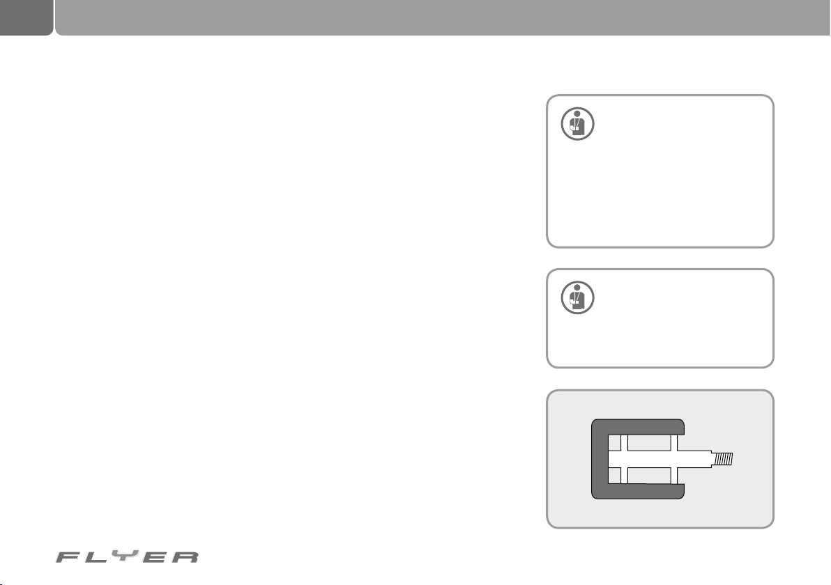
If your pedals are produced with
a rubber or plastic coating, first
carefully familiarise yourself
with the grip of the pedals. These types
of pedals are especially slippy in wet
conditions.
Page 15
6. Before every ride
11
Before every ride with your
FLYER, please check your bicy-
cle, because even after assembly, briefly leaving the bike in public
places or transporting it, functions can
change or parts can become loose.
Before every ride, please check that:
• The lights are working properly and are
safely secured. Key functions: the front
headlight and the rear light generate sufficient light, while the standlight function
works after you stop riding your FLYER.
• The bell is working safely and is properly
secured.
• The brakes are working properly and are
secure, and you have checked for wear on
the pads and braking surfaces. For hydraulic systems: Check the cables and connections for leaks!
• Correct tyre pressure, please see the chapter
on tyre pressure (33.4) as well as the specific
instructions from the manufacturer. These
are printed on the outside wall of the tyres.
• The tyres have sufficient tread depth and
are not damaged or contain foreign bodies.
• The wheels run true and are free of damage.
• Before every ride, check that the wheels are
securely fastened and are correctly secured
with fastening nuts or quick releases.
• The gear shift components are working and
are safely secured
• All quick releases (even after leaving the
bike for a short time in town etc.), screws
and nuts are secure.
• The frame and fork are not damaged, deformed or dented.
• Fork elements are working properly and
are safely secured.
• Handlebars, stem, seat post and seat are
secure and correctly positioned.
If you are not sure that your
FLYER is in perfect technical
condition, do not start your ride.
Please have your FLYER checked by a
specialist retailer first! Especially if you
subject your FLYER to intensive use (in
sporting or daily use), we recommend
regular inspections by your specialist
retailer. For information on what should
be inspected and the interval between
inspections, see chapter 30.1. The components crucial to your safety, such as
frame, fork, suspension and brakes
have a specific useful life. Exceeding
this useful life can lead to unexpected
failure of the components. This can lead
to falls and serious injury.
In addition to after a fall, if you
have not used your FLYER for
some time, have left it unattended in a public place or it has fallen
over, you must carry out the checks
listed above for your own safety! In case
of damage, aluminium parts cannot be
safely repaired. Carbon components
can suffer damage that is not identifiable with the naked eye or without specialist equipment.
Page 16
12
Adjusting the bike to the rider
7. Adjusting the bike to the rider
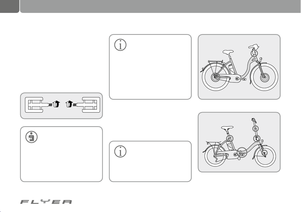
Your FLYER was carefully assembled by your
specialist retailer. If you have to remove the
pedals, such as during transport, you have
to ensure that the right and left pedal are installed on the correct sides when you re-fit
them. You can recognise which pedal belongs
on which side from the screws which turn in
opposite directions. Usually, an “R” is embossed on the right pedal with an “L” on the
left. Screw the right pedal clockwise and the
left pedal anti-clockwise into the cranks.
using them first in a safe place before
taking to public roads. Using so-called
“click pedals” which are unfamiliar to
you can result in falls and injury. Please
read the operating manuals from the
shoe and pedal manufacturer. These
will also contain an explanation of how
to adjust the amount of effort needed to
release the shoe from the pedal.
If you use system pedals which
hold the shoe on the pedal using
a special mechanism, practice
L
Pedals have to be screwed in
with the correct spanner, usu-
ally a 15 mm spanner. Please
adhere to the correct torque when
screwing the pedals in, see chap. 33.3,
“Torques for screwed connections”.
Ensure that the pedals are fitted
straight. If they are fitted at an angle,
there is a danger of breaking and of
having a fall! Quick releases on the FLYER Folding bike
R
7.1 Setting up the seating position
To use the FLYER safely and comfortably, the
seat, handlebars and stem have to be set up to
your physical dimensions and desired seating
position.
Only allow specialists to work
on your handlebars and stem,
do not attempt to do this work
yourself. These are components which
are crucial for your safety, so incorrect
work and tools in this area of the bike
could lead to serious falls.
Possible positions of quick releases on the FLYER
Page 17
13
The seat and stem can be attached
with screwed connections or quick
releases. Always secure screwed
connections with the correct torque, see
chapter 33.3.
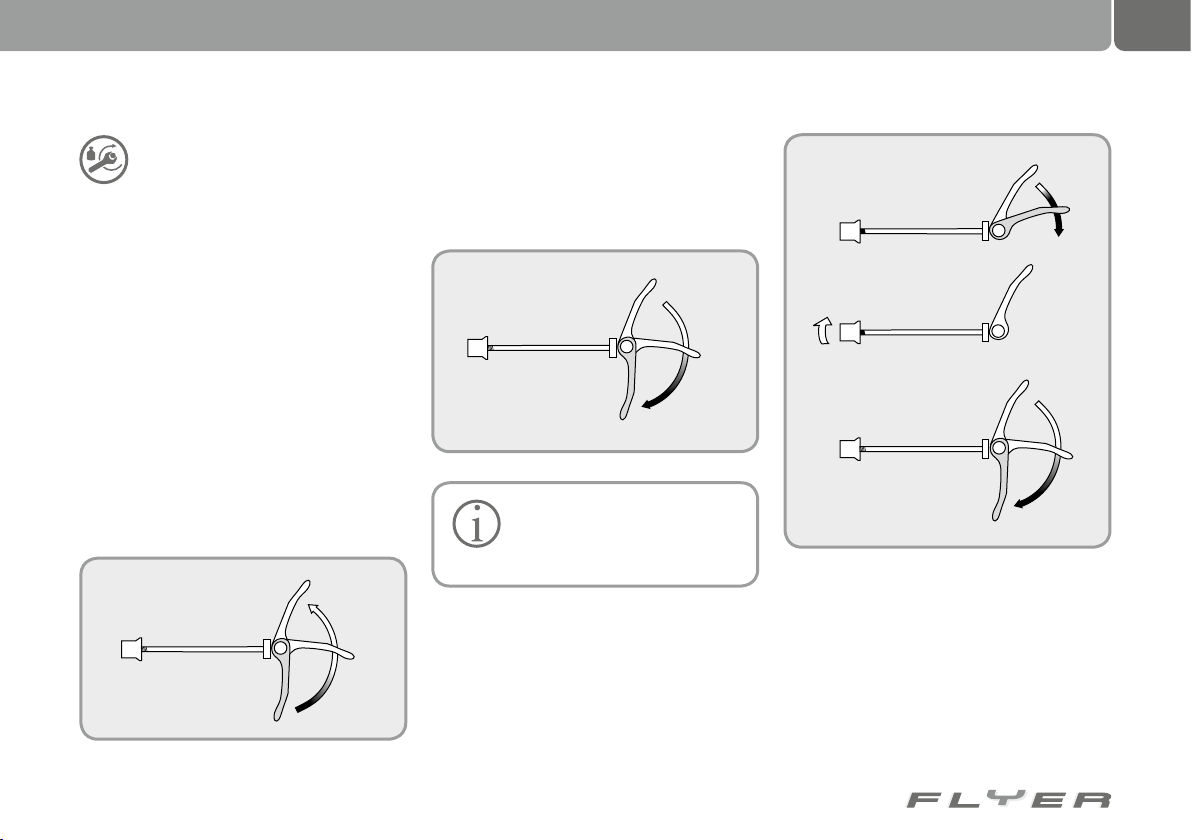
7.2 Operating quick releases
Quick releases are clamping brackets which
attach components like a screw, however their
clamping force stems from tightening the lever
without tools. The clamping force is activated
by opening and closing the lever. The level of
force is adjusted by turning the corresponding
bolt when the lever is open.
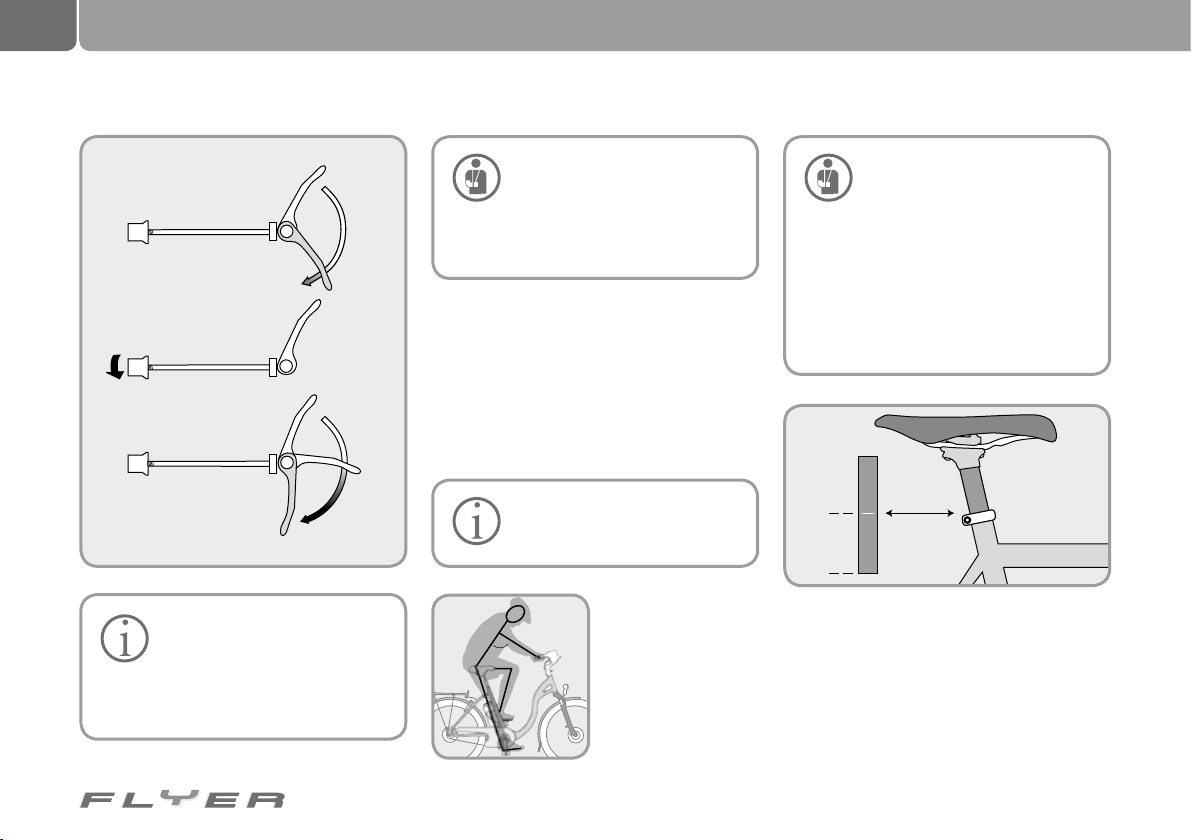
1. In order to open a quick release, e.g. to adjust the seat post, open the quick release
lever. On the inside of the lever, most quick
releases are printed with the word “open”.
2. Now you can move and adjust the seat post.
3. Before you use the FLYER, you first have to
securely close the quick release again. To
do this, push the lever closed so that you
can see the word “close” printed on the outside of the lever.
The quick release is only securely closed when you need
the power of the ball of your
hand to close the lever.
If the clamping force is not great enough,
meaning e.g. that the seat is not secure, you
have to turn the adjusting screw on the quick
release clockwise. To do this, the quick release
lever has to be open.
If the clamping force is too high and you cannot close the quick release, you have to open
the lever and turn the adjusting screw anticlockwise.
Page 18
14
7,5 cm
STOP
9
0
˚
Adjusting the bike to the rider
Always close quick releases in
such a way that the end of the
lever is close to bicycle and is
pointing backwards/downwards. In this
way you can avoid unintentionally opening the lever.
Please check that all quick releases are securely fastened,
even if your FLYER was only left
unattended for a short time.
You can only set off on your ride if all
quick releases are securely fastened.
7.3 Seat height
In order to transfer the pedal force effectively
to the pedals, you have to set your seat to the
appropriate height.
The ideal height is if you are sitting on your
FLYER, and the crank is in a vertical position and
you place your foot with the heel on the pedal.
Allow somebody to aid you in
doing this or lean against a wall
or railing.
Now the bottom leg
should be stretched.
If this is not the case,
dismount, adjust the
seat in the required
direction and attempt
to do the same again.
There are markings on the seat
post which show how far you
can pull it out of the frame.
Never pull the seat post further out than
this maximum length marking! If the
seat post has to be pulled out further
to achieve the correct seating height,
please talk to your FLYER retailer. Never
ride with a seat post extended further
than the maximum marker as this could
result in serious falls and injury.
Page 19
15
90˚
7.4 Seat position
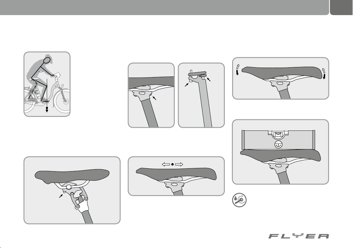
The horizontal position of the seat can
and should be set too.
You will ride most
effectively if the front
knee if directly over
the pedal when the
cranks are positioned
horizontally.
The knee should be positioned above the pedal.
To adjust the seat in the seat post, you have
to open the clamping screw at the back of the
seat post.
Depending on the model, it may also be necessary to loosen a screw at the front bottom
of the seat
Now you are able to adjust the position of the
seat backwards and forwards.
The angle of the seat can also be set when the
clamps are opened.
The upper surface of the seat should be horizontal.
After you have set the seat position
and angle, secure all fastening screws
with the correct torque. This will be
printed on the component itself or listed in this
operating manual (see chapter 33.3).
Page 20
16
90
100
80
70
60
10
0
STOP
90
100
80
70
60
10
0
STOP
90
100
80
70
60
10
0
STOP
50
40
30
20
90˚
9
0
˚
Adjusting the bike to the rider
7.5 Height of the handlebars
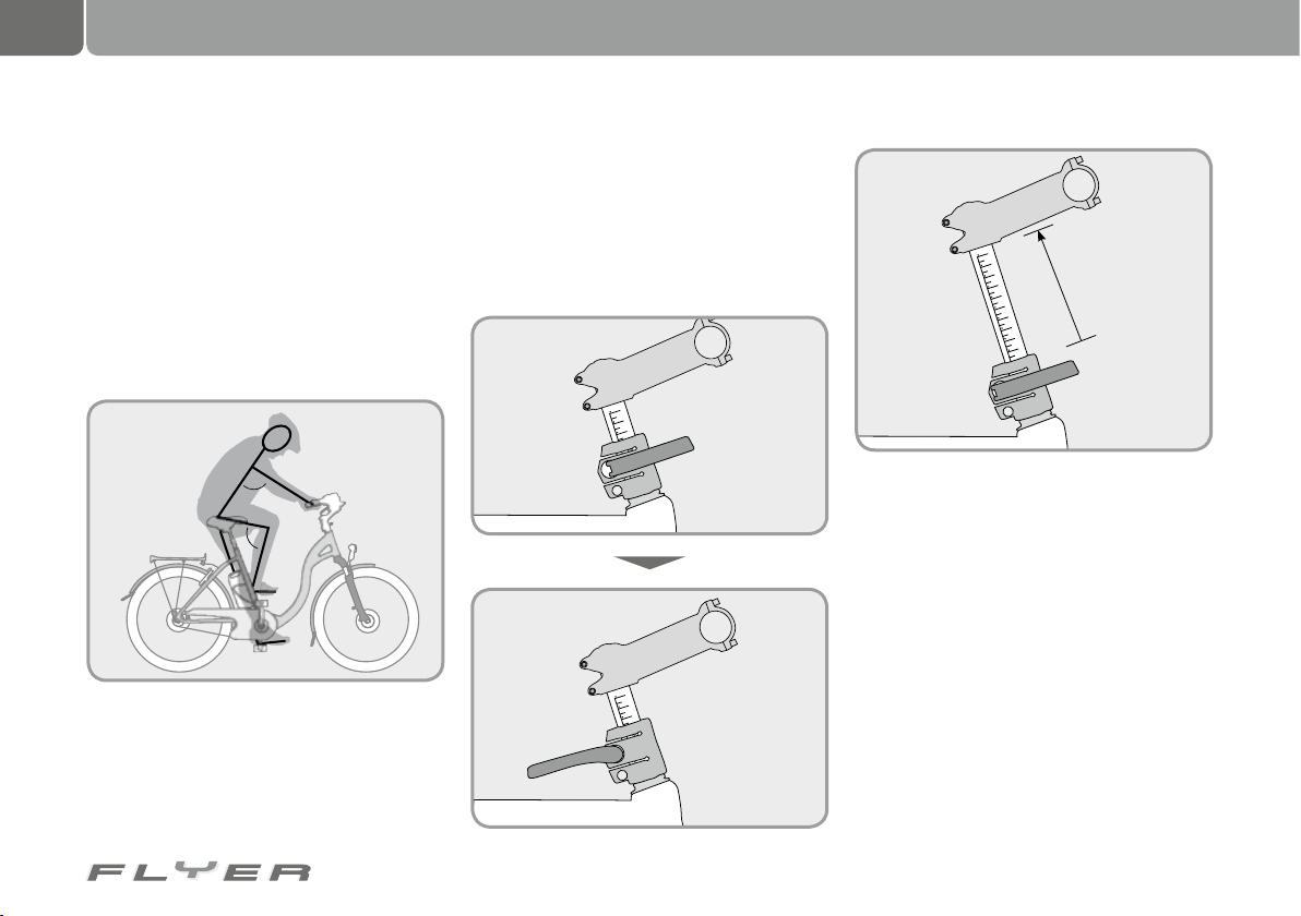
When the seat has been securely and comfortably positioned, the handlebars have to be set
to your requirements. Please allow a specialist
to do this.
An effective starting position for relaxed
riding is offered by a seating position in which
the upper body and arm form a 90° angle.
In order to change the height of the handlebars, the height of the stem has to be adjusted.
90° arm-upper body angle
Speedlifter
If your FLYER is equipped with a Speedlifter
stem, this can be done in an instant.
You only have to open the quick release lever
and pull the handlebars and stem upwards. When
the handlebars are in the desired position, close
the lever again completely.
The Speedlifter Twist System allows the handlebars to be turned to the side to save space,
e.g. during transport.
Open the quick release lever of the Speedlifter Twist by hand. Lift the safety bolt with
your fingers. Now you can twist the handlebars
to the side until the bolt automatically clicks
into its 90° position. Shut the quick release
completely, so that the handlebars are fixed.
When you twist the handlebars back into the
riding position and proceed in reverse order to
the process described above, the safety bolt
will once again click safely into place. Completely close the quick release, so that the
handlebars are once again secure. That’s it!
Ready to ride!
Page 21
17
10
0
STOP
10
0
STOP
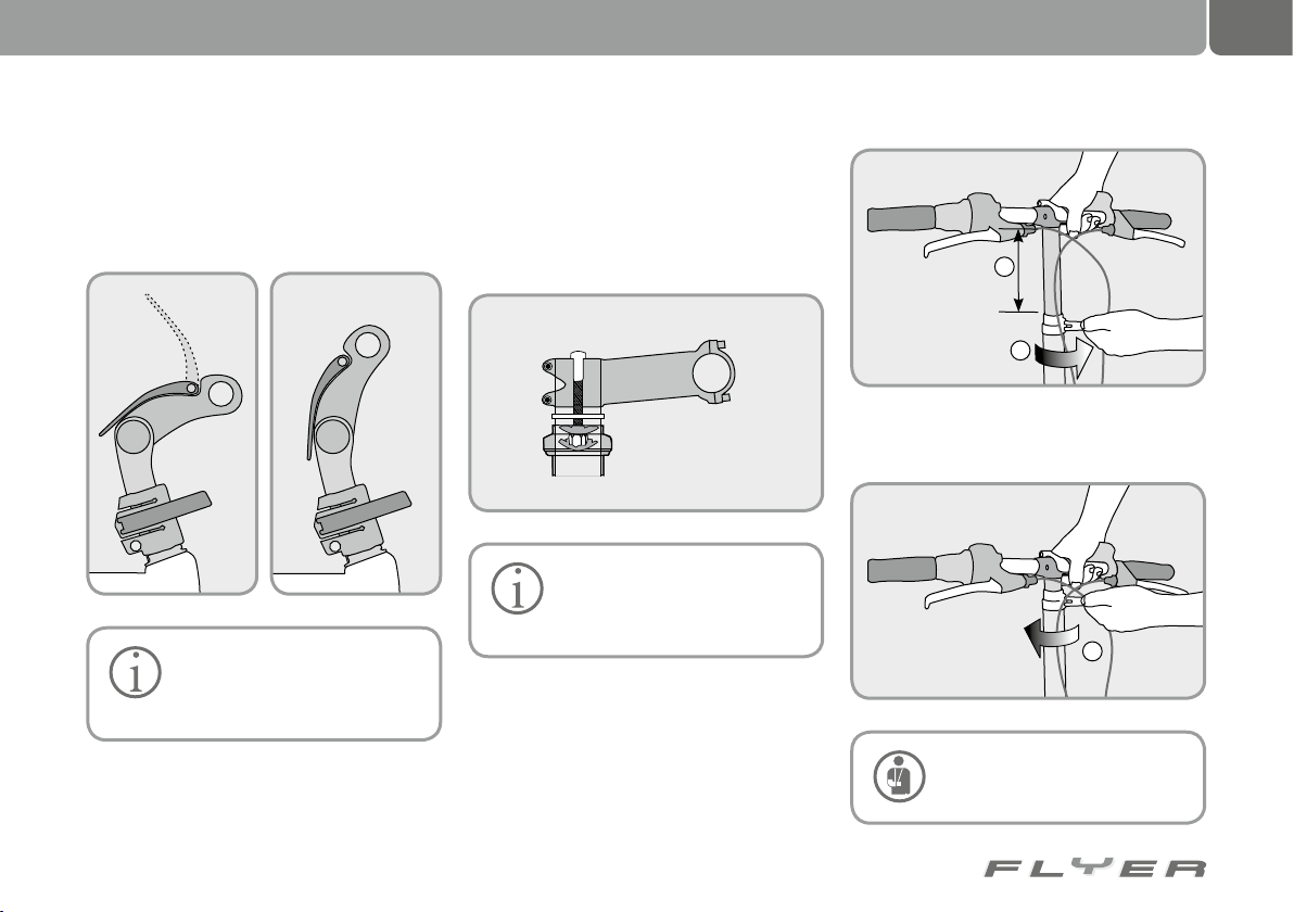
The optionally available angle-adjustable stem
is very easy to operate. Pull the lever on the top
of the stem up in order to adjust the stem. By
replacing the lever back in its original position,
the stem is then fixed in place.
Please read the enclosed instructions of the component
manufacturer and get more in-
formation at www.speedlifter.com
7.6 Ahead stem
In order to adjust the height of an Ahead stem,
it is removed and spacer is either added or taken away. This adjustment work has to be done
by a specialist.
All FLYERs are equipped with
forks of the right length. In order
to safely add spacer here, a fork
with a longer shaft has to be installed.
7.7 Height of the handlebars on a
folding bike
In order to adjust the height of the handlebars
on a folding bike, all you have to do is open the
quick release on the stem shaft.
2
1
Position the handlebars with the stem at the desired height. Then close the quick release again.
3
The stem may only be pulled
out to the maximum length
marking
Page 22
18
The battery
8. The battery
There are two systems available for your
FLYER. One with 26V and one with 36V.
These two systems are not interchangeable. In other words, you may not charge or
operate a battery from the other system in your
FLYER.
The battery of your FLYER 26 volt system is
a Li-Ion Ni Co manganese battery.
An even more state-of-the-art Li-Ion Al
battery is used in the 36 Volt system. This combines the most advantages for use in a FLYER.
The main advantage of this type of battery is its
combination of low weight and large capacity.
You therefore save on weight but still enjoy a
higher battery capacity.
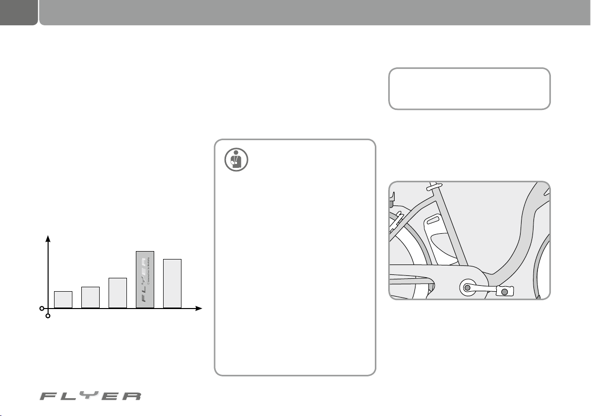
Range with same battery weight
Range (km)
Lead NiCd NiMH Li-Ion Li-Po
Both batteries are original Panasonic system components and the vital charging and
monitoring electronics (battery management system) have been optimally tuned to
the drive system and the original charger
by the manufacturer. The cells employed
are specifically designed for use in electric
bikes. This ensures that the batteries deliver optimal safety, capacity, long life and
the widest possible operating temperature
range.
Safety information about your
FLYER battery:
• This battery is exclusively intended
for use in FLYER electric bikes.
• Only use the FLYER charger for
charging the battery
• Do not overheat the battery
• Do not throw the battery in a fire
• Do not dismantle or modify the battery
• Do not hit nails into the battery
• Do not connect the (+) plus and (-) mi-
nus poles with metal objects
• Do not charge or use the battery in
high temperatures
• The reasons named above can cause
heat, fire or explosions.
• The battery has to be disposed of in
an environmentally-friendly way.
• Do not partially or completely immerse the battery in water.
• Do not expose the battery to a jet of
water.
• Do not use the battery when the housing has been damaged or opened.
• Only use original FLYER batteries.
8.1 Recharging the battery
The battery for the electrical motor of the
FLYER is located in a holder in the seat tube
below the seat.
8.1.1 Removing the battery
To charge the battery, it has to be removed
from its holder in the FLYER. To do this, take
the handle of the battery in your hand, place
the key in the battery lock and turn it anti-
clockwise.
Page 23
19
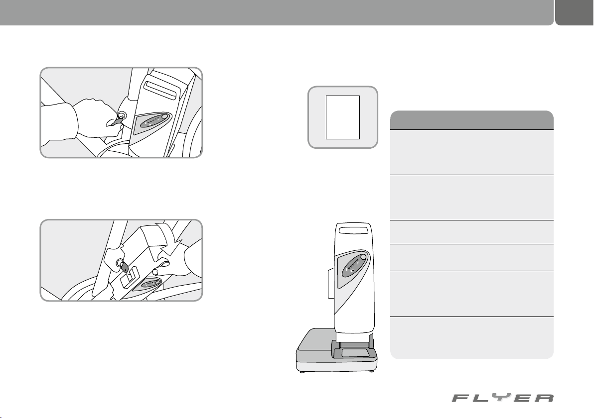
Mode Red LED Green LED
Battery NOT
connected/no
contact
NO lights NO lights
Battery
management
identifies the
battery
NO lights
Blinking
(1Hz)
Charging
process
NO lights Constant
Fully charged NO lights NO lights
Battery
management
is waiting for
a command
NO lights
Blinking
(1Hz)
Error
message
Blinking
(2Hz)
NO lights
This unlocks the battery, which can subsequently be removed from its holder.
It is removed by tipping it outwards at approx.
45° and then lifting it diagonally upwards.
Be careful, the battery is heavy. Hold on to it
tightly when you tip and remove it from your
FLYER. It is a good idea to remove the key after doing this and keep it safe, so that it is not
damaged or lost.
8.1.2 Charging the battery
Caution: The charger for
your battery contains
specific instructions
which you should first
read and take note of.
First, remove it from its
packaging and place the
battery within it in the
same way as you removed it from the FLYER.
Then connect the charger to a mains socket
(observe type plate, 230 V). Select a suitable
location for charging. This should be dry, stable
and flat. Do not cover the battery during charging as the process generates heat which has to
be able to escape.
When the charging process begins, the light diodes,
called LEDs here, light up on
the battery. The battery is only
completely charged when all
5 LEDs have gone out.
If your FLYER has an operating voltage of 36 V, the
charger will display any error
which could have occurred.
If you have acquired
a speed pedelec with
an operating voltage
of 36 V, the charger
shows the current
Info
status (including possible errors) using a number of different LEDs. The red and the green
LEDs on the charger light up or blink in a certain combination.
Page 24
20
The battery
After completing the charging process, please
remove the power cord of the charger from the
mains. Remove the battery from the charger
and disconnect the charger from the mains if
you are not using it in the foreseeable future.
8.2 Re-fitting the battery
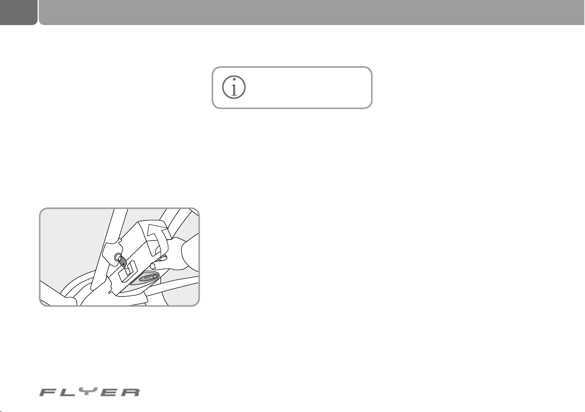
Re-fit the battery into the bike in the reverse
order of how you removed it; it should be tilted
at 45° as it is re-inserted. The battery holder
has guides which ensure that the corresponding elements at the bottom of the battery are
correctly in place.
Now tilt the battery back in towards the pedelec. There should be an audible click as it
slots into place. Please check that the battery
is secure.
There is no memory effect. For
that reason, you should charge
the battery after every ride.
8.3 Battery management
• The battery contains a management system which communicates individually with
the internal cells and ensures that the battery switches to sleep mode if unused for
a longer period of time in order to protect
against deep discharge.
• Your charger has an electronic protection
system against overcharging. Nevertheless, you should remove the battery from
the charger when it is fully charged. If you
pull the plug of the charger from the mains
socket, you also save energy.
8.4 Storage
• The best way to store the battery is with a
75-100% charge. Check this charge level
roughly every 12 weeks and recharge if required.
• The battery should be stored in a cool and
dry place (ideally 5°C, but not over 20°C if
possible).
• The Li-ion technology has a minimal selfdischarge.
• To avoid deep discharge, the battery switches itself into sleep mode. Depending on the
charge level, this will be activated after a
period of either a few days or several weeks.
• The battery can be “woken up” from this
sleep mode by charging the battery for a
short time in your charger.
Page 25
21
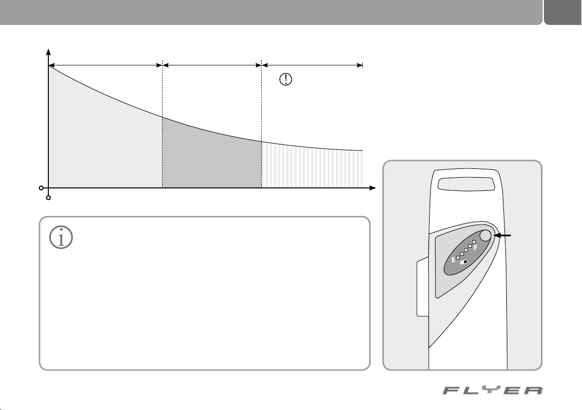
Long charging times Optimal temperature range
Charging time
-10°C 0°C 10°C 20°C 30°C 40°C 50°C
Please take note of the following information in order to
increase the life span of your
FLYER battery.
• Ensure that the battery is completely
charged before initial use and after
longer breaks between usage.
• If you have problems with the battery,
insert it into the charger. This resets
the battery, with the battery management e.g. “waking” the battery from
sleep mode. After that, the battery
should work normally again. If this is
not the case, please contact your specialist retailer.
for the charging process
• The best temperature range to charge
the battery is between +10°C and
30°C. At low loading temperatures,
the charging time is longer while the
battery does not charge at temperatures over +30°C. The best thing to do
is charge and store the battery in the
house in the case of cold temperatures outside or in a warm garage. In
this case, it is advisable to insert the
battery into your pedelec only shortly
before riding.
• If you are transporting your pedelec
by car, please remove the battery from
its holder and transport it separately.
Battery could
be damaged
8.5 Checking the charge level
On the side of the battery (on the left hand side
when facing forward) there are five red LEDs
and a red button (“Push”)
If you briefly press on this red button
(“Push”), the LEDs light up. The number and
type of lights provide information on the charge
level of the battery.
Page 26
22
Battery
Remaining
capacity
In approximate
distances ridden
10 Ah 6 Ah approx. 18 500 km
12 Ah 7,2 Ah approx. 29 000 km
16 Ah 9,6 Ah approx. 50 000 km
Display
Battery
charge level
5 LEDs light up ***** 80-100 %
4 LEDs light up **** 60-80 %
3 LEDs light up *** 40-60 %
2 LEDs light up ** 20-40 %
1 LED lights up * < 20 %
1 LED blinks < 10 %
No lights 0 %
E: Battery is empty
F: Battery is full
The battery
8.5.1 Checking the battery capacity
• Before every ride you should check whether
the battery charge level is sufficient for the
route planned.
• In winter, the range of your FLYER is reduced compared to its normal performance. Therefore you should store the battery in warm rooms and only insert it into
the FLYER shortly before riding.
• This helps combat the effect of reduced
range in low temperature conditions.
• The range can vary depending on topography, riding style, condition of the battery
and the level of support set.
If the LEDs on your battery blink
together (2-3 LEDs) or in sequence, the battery is damaged
Before having the battery
checked by your specialist re-
tailer, place the battery in your
charger for a short time and test it
again!
8.6 Life span and warranty of the
battery
The battery of your FLYER is a high quality product. It has a warranty of two years.
For more on this, please read the “Warranty”
chapter at the end of this operating manual.
8.6.1 Battery wear
The battery is subject to wear and is covered by
a two year warranty.
If a defect occurs during this time, your
specialist retailer will of course replace the
battery, however the usual signs of aging and
wear do not represent defects.
The life span of your battery is dependent
on various factors:
• The number of charging cycles
• The age of the battery
• The storage
Here, the aging process plays just as important a role as the number of charging cycles.
Depending on the type of battery, 500 - 1000
charge cycles are possible. The capacity loss is
approx. 10% per year.
After exceeding the technical definitions listed
above, the battery counts as being used.
The battery also ages if you do not use it.
Capacity is also lost in this case.
Page 27
9. The charger
23
If you have sufficient remaining capacity/
range, you can of course continue to ride with
the battery.
If you would like to dispose of the battery,
you can hand it over to your specialist retailer.
You can make the most of the life span of
your battery by fully recharging the battery after every ride.
The Panasonic Li-cobalt battery does not
have any memory effect.
If you would like to swap your
battery while you are on a ride,
please note that only rental battery boxes with the corresponding sticker can be used as replacements. This
exchange is free, however you should
reserve first if you are traveling in a
large group and will therefore require a
lot of batteries at once.
Please read the instruction sticker for the
charger before using it for the first time.
Only use the original charger supplied with the bicycle by FLYER.
If there is an error or the battery has entered
sleep mode, it can help to place the battery in
the charger for one minute. This allows the
battery management to check for, and possibly
repair, any errors.
If you have a 36 V charger, any possible errors are displayed with the green and red LED.
The meaning of the lights is listed in the chapter 8.1.2 “Charging the battery”.
Incorrectly operating the charger can lead to damage to the
charger itself or injury.
• Before cleaning your charger, always
first remove the plug from the mains
in order to avoid a short circuit and
bodily harm.
• Only use the charger in dry rooms.
• Only place the charger in a safe, sta-
ble position on a suitable surface.
• Do not cover the charger or place any
objects on top of it in order to avoid
overheating and fire.
Page 28
24
Lo
Power
Hi
Mode
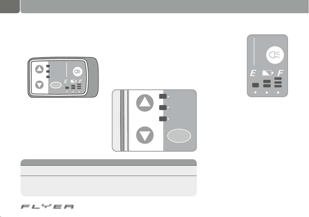
The upper LED (HI) The middle LED The lower LED (Lo)
Strongest support Middle support Weakest support
represents 150 or 200% of
your pedal force depending
on the model
represents 100 - 130% of
your pedal force depending on the model
represents 50 - 70% of your
pedal force depending on the
model
The display panel
10. The display panel
10.1 LED display panel unlit
The display panel on the handlebars has four
buttons and various display features.
Hi
Mode
In the middle of the panel is the on/off “Power”
button (orange).
This is used to switch the support on and
off.
On the left hand side, you will find both
“Mode” buttons (arrow up, arrow down). These
buttons are used to regulate the strength of
the motor support.
To the right next to these are the LEDs,
which show you the strength of the support
Lo
Power
currently being provided. After switching the
motor on, the middle support level is always
on. By pressing one of the “Mode” buttons,
you can select how strong the motor support
should be. Every press of the buttons switches
the support up or down one level, depending
on which button you apply. Every level of support can be applied by only pressing one of the
“Mode” buttons until you reach the desired
level of support.
The LEDs for displaying the charge
level of the battery
are located in the
bottom right.
The “Light” button
is located in the top
right. For enhancing
your safety, we recommend riding with
lights on
You can also use
the lights irrespective
of any motor support
If you turn off the motor support, the light
also turns itself off. However, you can switch it
on irrespective of any motor support.
The LEDs for displaying the charge level of
the battery are located in the bottom right.
Page 29
Battery charge level display
Display (after
2 seconds)
Battery charge
3 LEDs lit *** 70-100 %
2 LEDs lit ** 40-70 %
1 LED lit * 10-40 %
1 LED slowly
flashing °
< 10%
Now you will
start to notice
a slight loss of
performance.
1 LED quickly
flashing °
- 0%
The system will
soon switch
itself off.
Lo
Power
Hi
Mode
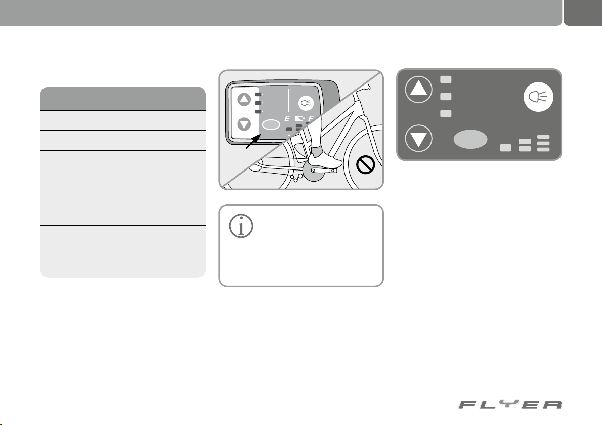
Please ensure that while switching on the bicycle as well as two seconds subsequent to this,
you do not place a foot on either of the pedals.
The sensor in the motor is adjusted
afresh every time it is switched on. It should
not be subjected to any force during these
two seconds.
25
2 sec.
Automatic switch off
If your FLYER does not move
for ten minutes after stopping,
the system turns off automatically. If you
would like to ride with support once more,
you have to press the “Power” button on
the screen once again.
Page 30
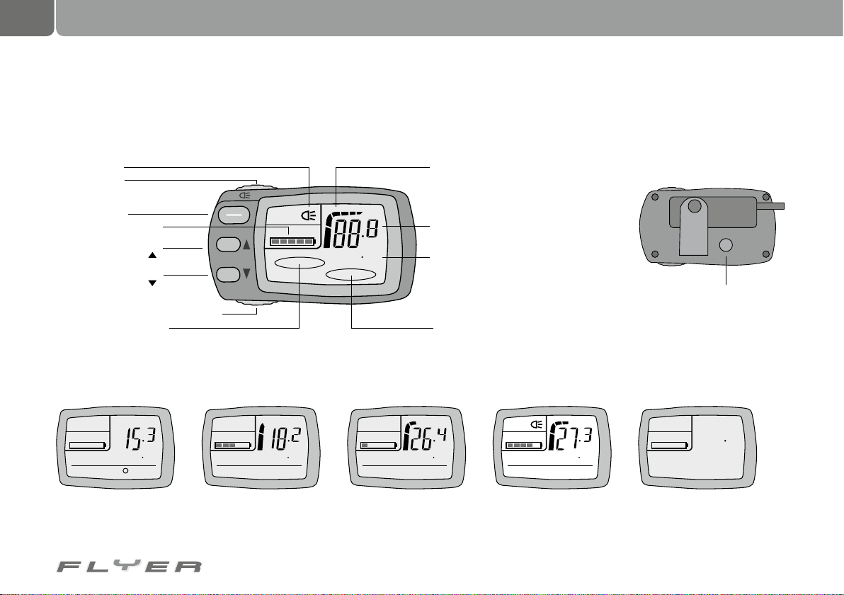
26
The display panel
10.2 LCD screen
Name and function of the individual buttons
Light display
Light button
Power button
Charge lever display
Button for selecting
the support mode
Button for selecting
the support mode
Button for selecting the function
Support mode display
Power
Assist
Mode
E F
0000
POWER
km/h
0
km/h
Energy consumption display
Speed display
Display showing:
• Distance
• Average speed
• Maximum speed
• Total kilometres
Display for speedometer functions
Display examples
POWER
E E E EF F F F
NO ASSIST
No support +
Average speed
20
KM/H
/
km/h
5
km/h
ECO
247
km/h
TAGES-KM
POWER
km/h
6
STANDARD
GESAMT-KM
359
km/h
POWER
km/h
5
POWER
km/h
STANDARD
max km/h +
Background lighting on
36
km/h
MAX-KM/H
2
View of the rear side
Overall reset button
POWER
km/h
km/h
View when switched offTotal kilometresTrip kilometres
Page 31
27
POWER
km/h
km/h
0000
0
Power
Assist
POWER
km/h
km/h
0000
0
Mode
POWER
Power
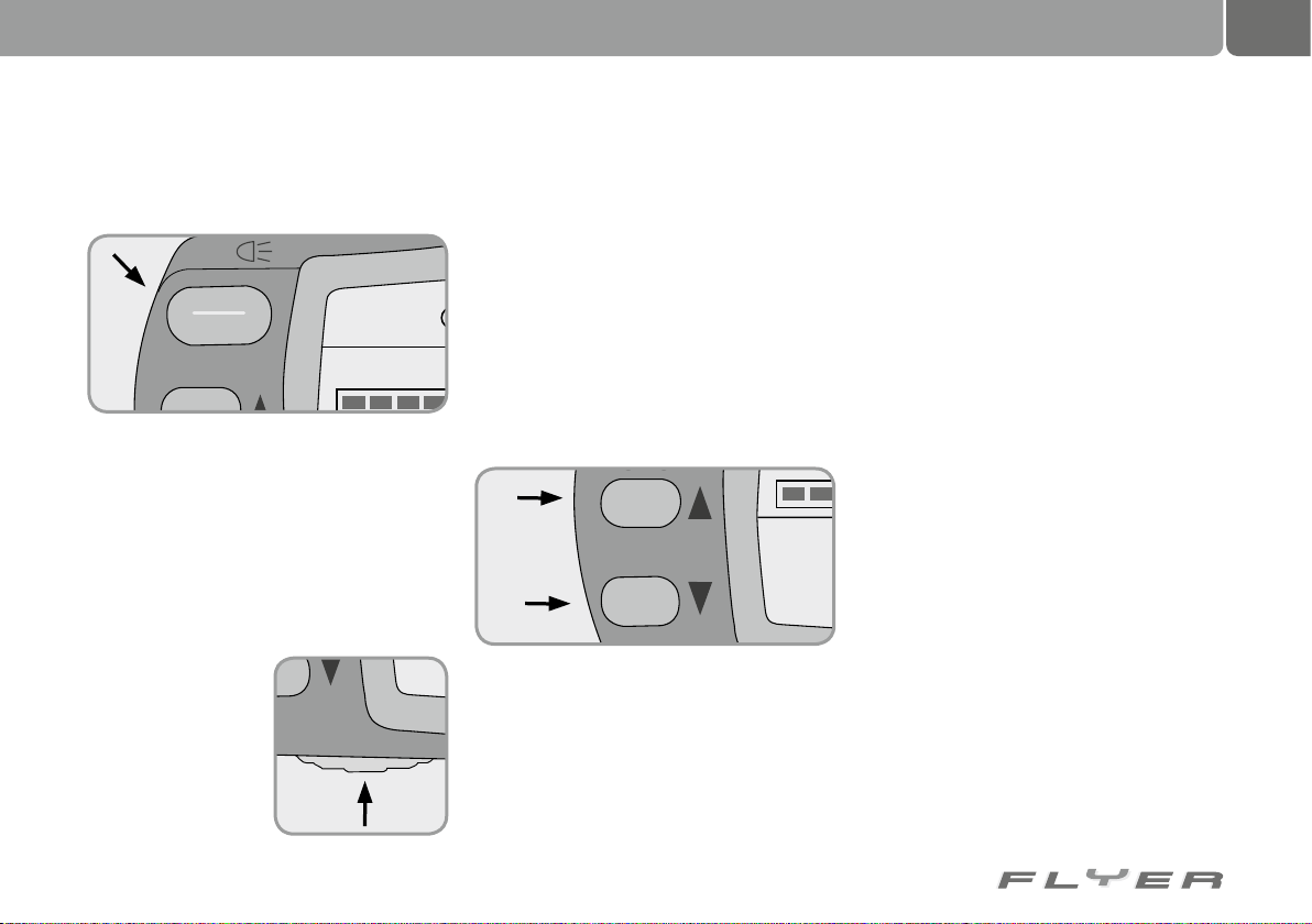
“Power” on/off button
If you apply the “Power” button, the screen and
motor support are switched on.
The middle “standard” support is always activated after switching the system on.
The background lighting lights up briefly
and then disappears again.
All recordings (see bottom row on the previous page) are started, as soon as the screen is
turned on and then stopped when it switched
off again.
“Mode” button
When you apply the
“Mode” button, you
can switch the display to speedometer
function.
If the button is applied, in sequence the following
functions are displayed
• Km/h = Current speed
• Trip = Trip distance
• Average speed
• Max Km/h = Max speed
• Total Km = Total kilometres ridden
Here, the setting which was displayed last on
turning off will be shown first when switching on.
Changing support
You can regulate the strength of the motor
support by applying one of the two “Assist”
buttons.
If you would like stronger support, press the
upper of the two buttons, the arrow of which is
pointing up/forwards.
If you would like weaker support, press the
lower of the two buttons, the arrow of which is
pointing down/backwards.
The level of support changes every time
you press the buttons.
Every level of support can be applied by
only pressing one of the “Assist” buttons until
you reach the desired level of support.
There are four levels of support.
• NO ASSIST = No support
• HIGH = Strongest support
represents 200% of your pedal force
• STANDART = Medium support
represents 120% of your pedal force
• ECO = Weakest support
represents 70% of your pedal force
In NO ASSIST mode, your FLYER will operate
like a normal bicycle and the motor does not
work.
Resetting the display field
Hold down the “Mode” button for longer than
three seconds, then the “Trip distance”, “Average speed” and the “Highest speed” are reset
to zero. The “Total kilometres” remain at the
cumulative level.
Page 32
28
POWER
Description Display range
Speed 0,0 - 99,9 km/h
Trip
0.0 – 99999 km (When
the distance ridden
reaches 9999.9 km, the
display shows the distance without a decimal
point.)
Average speed 0 - 99,9 km/h
Highest speed 0,0 - 99,9 km/h
Total distance
0.0 – 99999 km (When
the distance ridden
reaches 9999.9 km, the
display shows the distance without a decimal
point.)
The display panel
Background lighting and light.
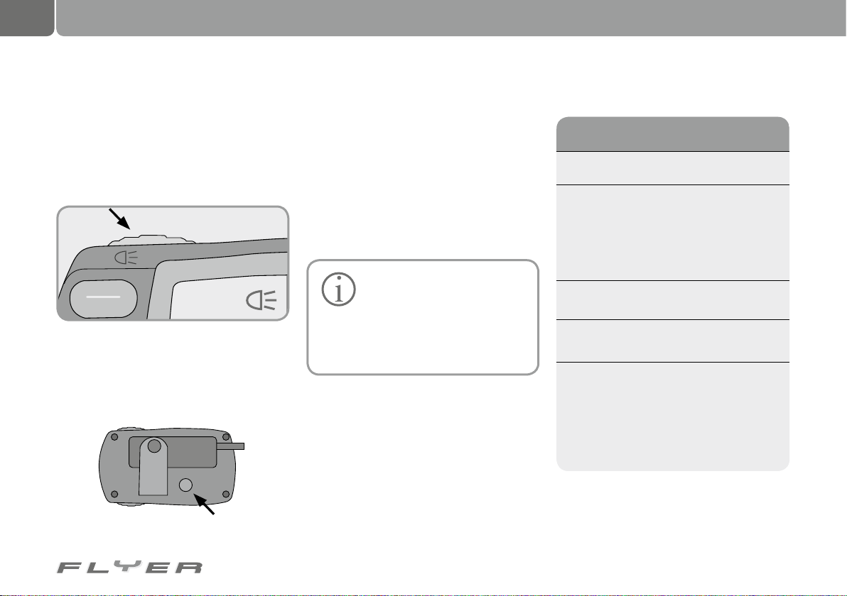
In order to switch the back-lighting of the
screen on or off, simply apply the “Light” button.
In order to switch the pedelec light on or off,
simply apply the “Light” button.
For enhancing your safety, we recommend
riding with lights on.
Deleting all data
To do this, hold down both “Mode” buttons
and the “Overall reset” button on the rear of
the display at the same time for approx. three
seconds.
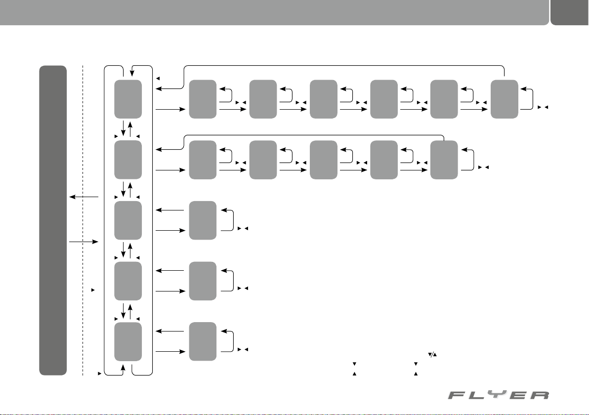
Setting and saving language, contrast and
wheel size
By pressing the buttons “Mode” and “Downward arrow” you can enter the screen programming section. Here you can set the
desired levels as described in the separate
instructions. You can select from five possible
languages. The contrast can be varied in ten
steps. The wheel size can be set here in 1 mm
steps (10 mm - 3999 mm). To save the settings,
please press the light button.
Automatic switch off
If your FLYER does not move
for ten minutes after stopping,
the system turns off automatically. If you
would like to ride with support once more,
you have to press the “Power” button on
the screen once again.
10.2.1 Measurement and display ranges
Page 33
29
Standard display
ESetup mode
Display mode
Light button confirms the settingsSwitch button display & button for 3 sec.
button
Trip setup
button
setup
Wheel size
button
setup
km/h or mph
button
setup
LCD contrast
button
settings
Language
button
button
button
button
button
button
Switch
button
Switch
button
Switch
button
Switch
button
Switch
display
display
display
display
display
setup
Total trip
(6th position)
setup
Wheel size
(5th position)
setup
km/h or mph
LCD
mode
contrast setup
mode
Language setup
Switch
Switch
button
button
display
button
button
display
button
button
button
button
button
button
button
button
Total trip
Wheel size
setup
(5th position)
setup
(4th position)
button
Switch
button
Switch
button
display
button
display
button
button
Total trip
Wheel size
button
setup
(4th position)
setup
(3rd position)
button
setup
Total trip
button
Switch
display
button
button
setup
Wheel size
button
Switch
display
* For faster shifting, press the button for longer than 2 seconds
* button stands for the button in the support select
* button stands for the button in the support select
(3rd position)
button
Switch
(2nd position)
button
Switch
button
display
button
display
button
button
Total trip
Wheel size
setup
(2nd position)
Switch
setup
(1st position)
button
button
display
button
button
button
Total trip
setup
(1st position)
button
button
Page 34
30
POWER
km/h
E F
Display
Battery
charge level
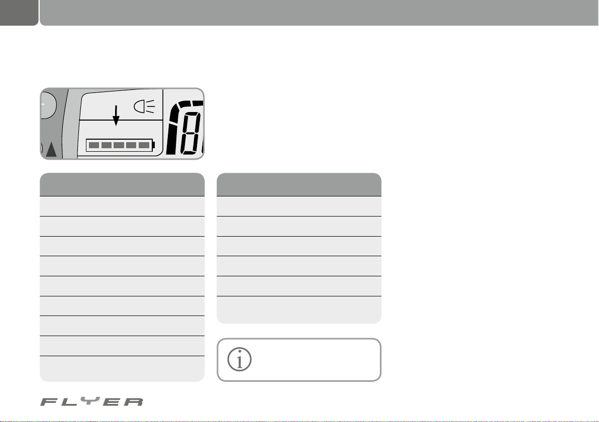
5 LEDs light up ***** 80-100 %
4 LEDs light up **** 60-80 %
3 LEDs light up *** 40-60 %
2 LEDs light up ** 20-40 %
1 LED lights up * < 20 %
1 LED blinks < 10 %
No lights 0 %
E: Battery is empty
F: Battery is full
If you see...
Energy
consumption is...
6 bars More than 20 amps
5 bars up to 16-20 A
4 bars up to 12-16 A
3 bars up to 8-12 A
2 bars up to 2-8 A
1 bar up to 0-2 A
The display panel
10.2.2 Battery charge level display 10.2.3 Energy consumption display
The energy consumption display shows the current energy consumption at one of six levels.
You can improve this by riding economically.
This increases your riding range.
The fewer of the six bars displayed, the less
the energy consumption.
The more of the six bars displayed, the
greater the energy consumption.
The display shows nothing in
the case of very low energy
consumption
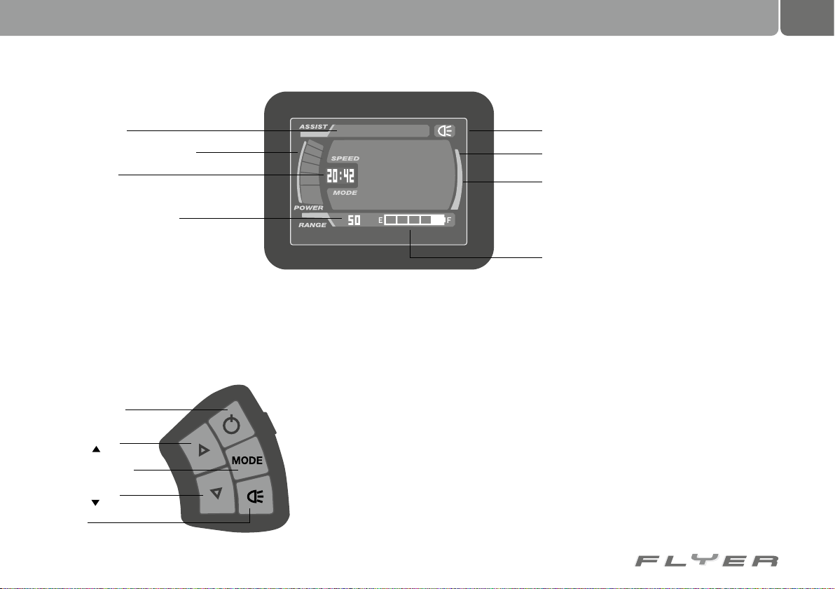
10.3 Large LCD screen
A large, centrally positioned LCD screen is also
available as an optional extra. In addition to
the functions of the normal LCD screen, it also
displays the time of day and the remaining distance which can be ridden with support.
After switching the system on, the distances and speeds achieved are displayed which
were last displayed before switching off.
In addition to all functions of the normal
LCD screen, the large screen also shows the
time of day in hours and minutes. “00:00”
blinks when the clock battery is empty.
As a warning, the Assist mode blinks when
the motor is being overburdened. As soon as
this period of excess burden has subsided, the
screen will return to normal.
Page 35
31
Support level
Motor performance display
Time of day
Remaining distance
with this battery charge
It also has a “Delete all data” button
(on the rear).
10.3.1 Operating the large LCD screen
This large LCD screen is operated with its own
handlebar switch.
The control panel
Power button
Mode select
button
Support button
Mode select
button
Light
STANDARD
25
.9
km/h
GESAMT-KM
km
Button assignment:
Power button: Switches the electronic system on.
All data is immediately displayed. Pressing this
button again switches the electronic system off.
Mode select button: Pressing the button with
the arrow pointing up switches into a stronger support mode, while pressing the button
with the arrow pointing down switches into a
weaker support mode. By continuing to press
the buttons you will jump from the strongest
support to the weakest, and vice versa. The following modes are available:
• Eco
• Standard
• High
• No Assist
Lighting display
Speed
Plus:
• Distance of current trip
• Total distance covered
• Average speed
• Maximum speed achieved
Battery charge level
When you launch the system, the Standard
mode is switched on.
The screen also displays any possible
errors.
Error messages
Error code displayed on the speed display
E1: Zero calibration error
It is not possible to calibrate the sensors due
to overstress. Did you touch the pedals while
switching on? Please do not place a foot on the
pedals while switching on!
E2: Missing signal from speed sensor
The sensor has moved. Please reposition the
sensor.
Page 36
32
The display panel
E3: Communication error
A cable is possibly jammed or damaged
E9: Motor defect
In case of E1, E9:
• “No assist” is displayed
• There is no support
• Light can be switched on
• The remaining battery charge is displayed
• It is possible to reset the displays
Deleting data
In order to delete all data including the total
distance ridden, press the Mode button on
the control panel and the Reset button on the
rear of the screen at the same time. This also
launches the Setup mode.
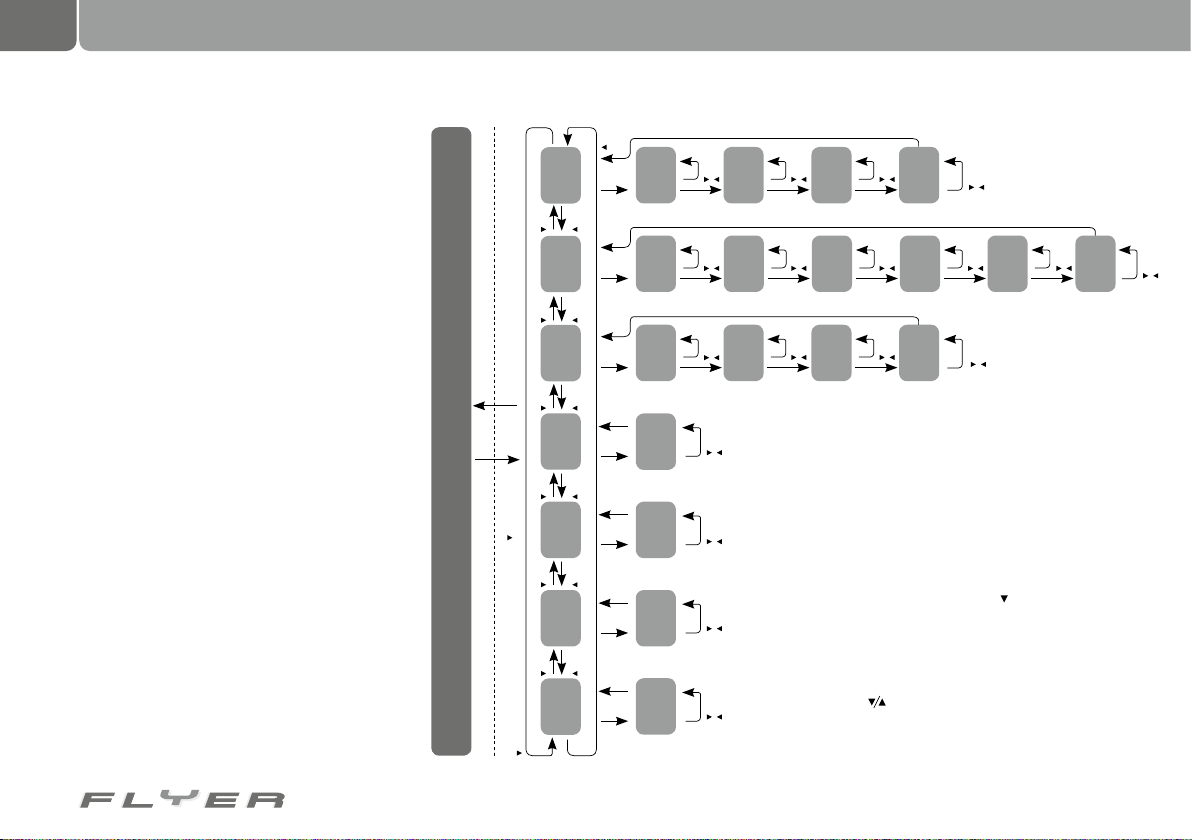
Programming the system/Setup
In order to set up or program the screen/display, press the “Downward arrow” button and
the “Mode” button on the control panel at the
same time for three seconds. The programming/screen setting mode starts with setting
the desired language, while at the same time all
data (including the total distance ridden) is set
back to zero. The setup is structured as follows:
Normal mode
Normal mode
Setup mode
Light button (for saving every setup option)
Press mode select button & button for 3 sec.
button
Set
button
Set the
button
Set the
button
Set the unit of
button
Background
button
Set up
button
Set
the time
button
total km
button
wheel size
button
measurement
button
lighting
button
contrast
button
language
button
Mode
Mode
Mode
Mode
Mode
Mode
button
button
button
button
button
button
time
position)
Set the
th
(4
position)
Set the
total km
th
(6
position)
Set the
th
wheel size
(4
measurement
Set the unit of
lighting
Background
Set up
contrast
Set
language
Mode
Mode
Mode
button
button
button
button
button
button
button
button
button
button
button
button
button
Set the
Set the
Set the
button
button
button
button
button
button
time
position)
rd
(3
position)
total km
th
(5
position)
rd
wheel size
(3
of measurement)
(Select the lighting)
Set the
Mode
button
button
button
Set the
Mode
button
button
button
Set the
Mode
button
To switch between the setups, press the mode button for
3 seconds
While switching between setup options, the trip kilometre,
average speed, top speed, total trip displays are switched off
(as the display elements are being used for the setup)
time
nd
total km
th
nd
wheel size
position)
(2
position)
(4
position)
(2
Mode
Mode
Mode
button
button
button
button
button
button
button
button
button
Set the
Set the
Set the
time
st
total km
rd
st
wheel size
position)
(1
position)
(3
position)
(1
Mode
button
button
button
button
button
button
button
(Select the time)
Set the
(Select the wheel size)
Other displays are shown in normal mode.
By pressing the button for 2 seconds, you can switch
between the setup options
(Select the language) (Select the contrast) (Select the unit
By pressing the Light button, setup mode is closed and the
changed settings are saved.
total km
nd
position)
(2
Mode
button
button
button
Set the
position)
total km
st
(1
(Select the total km)
button
button
Page 37
11. The electrical motor
33
The electrical support
How does the support work?
The motor starts to work as soon as you
turn on the support and start to pedal. The law
states that the speed which is possible solely
from the motor’s power is limited. The performance of the motor is tied to your pedalling.
You can influence the performance provided by the powerful Panasonic motor in various
ways:
• Selecting the support mode: Depending on
the support mode selected and the model,
the motor provides up to x2.66 your own
pedal force. A weaker support mode does
not aid as strongly but does have a wider
range. A stronger support mode is for ex-
ample useful on steep hills, or if you are in
a hurry.
• Your own pedalling. The more powerfully
you pedal, the more performance the mo-
tor will also provide. This naturally also
increases the energy consumption and re-
duces the maximum possible range.
• Riding with a suitable cadence. The mo-
tors of the various models are optimised for
various riding styles and cadences. Perfor-
mance and energy consumption match var-
ious high pedalling frequencies. Commonly,
everyday users and tour riders ride with a
lower cadence than sports riders. Please
ask your FLYER retailer which approach is
best for you.
The range of your FLYER is optimised to the
state of the art. It is influenced by the battery
you select as well as various other factors.
These include:
• The technical condition of your FLYER:
Ensure that you have sufficient tyre pressure, a well maintained chain and that
nothing is rubbing during riding.
• The ambient temperature: When the am-
bient outdoor temperatures are cold, batteries offer lower capacity and discharge
faster. It is useful to insert the battery into
your FLYER only shortly before starting your
ride after keeping it in a heated room.
• The riding style: In general, riding in lower
gears and with a higher cadence results
in greater range. The power sensor registers if you are riding with high power input
in high gears. You will then be supported
more strongly, but this comes at the cost of
the reduced range.
Page 38
34
Frame
12. Frame 13. Headset
Frame shapes vary according to the type and
function of the pedelec. Modern frames are
made of various materials, such as steel, aluminium alloys or carbon (carbon fibre). Thanks
to the evolution in materials and construction
techniques, it is nowadays possible to produce
all shapes of frames safely so they perform
stably during riding. So despite a low stepthrough, you can still be sure that your FLYER
is always safe on the roads, even with luggage
on board.
If your pedelec is stolen, it can
be identified using its frame
number. Please always note
down the full number in the correct order. Otherwise it is impossible to make
a unique identification. In the documentation you received from the retailer
when you purchased your FLYER, there
is also a section where the frame number is entered.
The frame number can also be engraved on various parts of the frame. On
pedelecs, it is often located on the motor
mount. Other possible areas include the
seat post, the dropouts or the bottom
bracket shell.
On no account should you ride
with a bent or broken frame.
Never attempt to repair damaged parts yourself. Otherwise, there is
a danger of accidents. Faulty parts have
to be replaced by a specialist retailer.
Please only ride your pedelec again
when the parts affected have been replaced.
Please have your pedelec checked by
a specialist retailer after an accident or
fall. Please only ride your pedelec again
after this check has been carried out.
Faults on the frame or other parts can
cause accidents.
If your pedelec does not ride in a
straight line without any problems,
this can be due to a bent frame or fork.
Please contact a specialist retailer to
have the frame and fork checked and
possibly to have the bike realigned.
The fork is held in the frame by the headset.
It allows the rider to turn the handlebars and
fork. If the headset is correctly set up, it can
be turned easily. It should not exhibit any play.
The headset is subject to high levels of
strain when riding over bumps. This can lead to
the headset becoming loose or out of position.
You should regularly have the headset checked
by a specialist retailer for play and ease of
movement (for inspection schedule see chapter 30.1 “Inspection plan”)
An improperly set up headset or
one that is too tight can destroy
the part. Please only allow a
specialist retailer to set up the headset
on your bike.
Page 39
14. Fork 15. Suspension frames and suspension-related parts
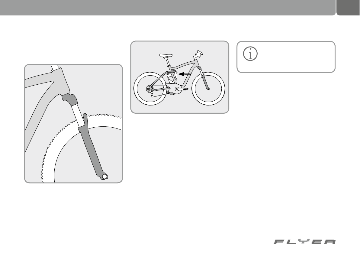
The fork holds the front wheel in the frame. The
stem is attached to the top of the fork shaft, and
the former holds the handlebars in place.
Modern pedelecs are nowadays almost all
equipped with suspension forks. This part helps
cushion the impact of bumps on the driver and
also helps keep the front wheel safely on the
ground on uneven surfaces. This allows braking
and steering forces to be safely transferred.
Suspension
The suspension on your FLYER combines two
functions.
• If you ride over something uneven, such as
the curb or a pothole, a great deal of the
forces exerted in the bump are absorbed by
the suspension parts. You are not only able
to ride more quickly but also enjoy a safer
and more comfortable ride!
• The shock absorbers ensure that the vibrations caused are quickly released again.
This allows the wheels more contact with
the ground and enables better control.
If you are riding a FLYER bicycle with full suspension, another suspension/shock absorber
part is integrated into your frame.
A differentiation is made between suspension
parts which work with a steel spring and those
with an air chamber. This results in differences, specifically affecting the weight of the bike,
although both types fulfil the functions listed
above.
be set up by the specialist retailer to match the
weight of the rider and the type of use. This
setup work requires both specialist knowledge
as well as experience and specialist tools,
therefore please leave this setup work to specialist retailers!
ing characteristics after being set up:
• The movement of the suspension fork and
• The so-called “sag” is adjusted to the type of
Keep to the suggested inspection intervals in order to maintain the functionality and to
keep any warranty claims valid.
To ensure functionality, the chassis has to
Suspension parts should exhibit the follow-
suspension seat post should be tangible when
riding over uneven ground, but should not compress to the end of their travel.
use. When the rider sits on the bicycle, the
suspension goes down. This travel, of the
compressed suspension while standing still, is
known as “sag”. City, touring and hybrid bikes
have a sag totalling 10-15% of the total travel.
35
Page 40
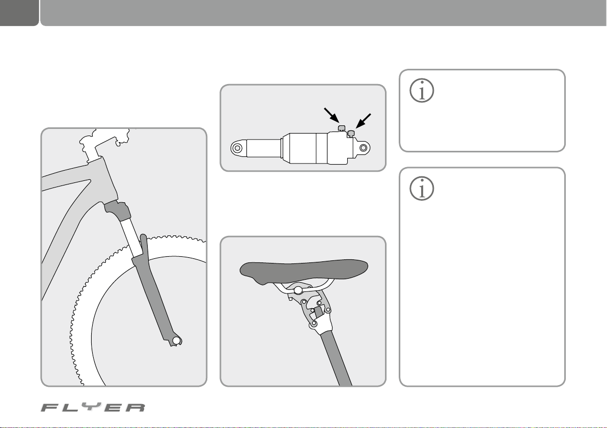
36
Suspension frames and suspension-related parts
Please note that the suspension part possibly
has to be set up again if you ride with higher
loads, such as during a cycle tour.
A typical suspension resembles the following:
Your rear shock absorber can look like this:
Shock absorber
adjustment
You can identify the location of the suspension
part in the frame using the diagram above.
Suspension seat posts have proven their
value in both daily use and on tours.
Spring stiffness
adjustment
Most suspension seat posts can
be individually adjusted to the
rider. For this purpose, the seat
post is equipped with softer or harder
suspension springs or the preload
changed. To do this, please contact your
FLYER retailer.
To ensure effective functional-
ity, it is important to regularly
clean the suspension parts. You
can purchase cleaner specifically for
this purpose from your specialist retailer although warm water and washing up liquid also suffice. Do not forget
to regularly grease the suspension
parts. You can purchase specialist oils
and conservation fluids at your specialist retailer.
Use a soft cloth to wipe the contact
surface of the shock absorber and the
fork, removing any dirt. In order to optimise the life span and performance
of your suspension, you can also apply
a special care oil (Brunox, Caramba,
available at specialist retailers) to all
contact surfaces, joints and gaskets.
The same applies for suspension
seat posts.
Page 41
37
Do not clean your bicycle with
a high pressure cleaner! The
pressure means that the cleaning fluid could also penetrate sealed
bearings on the fork, rear fork and suspension. Even if you continue to ride
with the bike, the fluid can no longer
escape and the parts can be destroyed
by corrosion in the long term!
Regularly check the joints of the rear
fork for play by holding the frame tight
and attempting to move the rear fork
sideways. The individual rear fork elements should be able to turn in the joint
but should not move sideways.
In addition, another good test is lifting the bike and quickly placing it back
on its wheels.
If you feel play anywhere on the
chassis, or even hear a clattering
sound, you have to contact your specialist retailer to identify and remedy possible problems!
Suspension and chassis components are vital parts on your
bike. Care for and check your
suspension-fitted bike at regular intervals or allow your specialist retailer to
carry out inspections.
The chassis is more effective for
longer if it is cleaned on a regular basis.
Warm water with a light cleaning agent
is suitable for cleaning this part of the
bicycle.
Check that all screws are correctly secured with a torque
spanner, ensuring that the correct torques have been applied. Otherwise, the screws could loosen or break,
releasing other components.
The full-suspension FLYER
is also permitted to ride with
a trailer. Regularly check the
trailer attachment and the mounting of
the suspension parts and the rear swing
arm in the frame. Riding with a trailer
places increased strain on the bike.
Check whether the parts named are still
free of any play and are secure.
Page 42
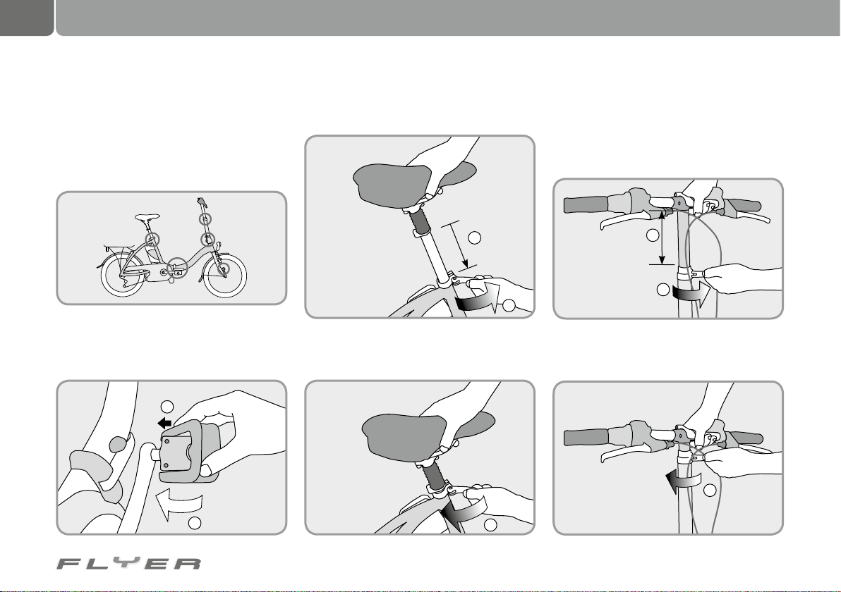
38
Suspension frames and suspension-related parts
15.1 Folding instructions for the
FLYER Folding bike
In order to make folding your FLYER simple
and safe, it has been equipped with quick releases in all the important places.
1. First fold the pedals of your FLYER. To do
this, push the sides of the pedals towards the
crank and fold them up to 90°.
1
2. Open the seat quick release and push the
seat post all the way down.
2
1
Then close the quick release again, ensuring
that the seat remains in position.
3. Open the quick release. on the handlebars
and turn the handlebars to point them in the
driving direction. Close the quick release.
Open the quick release below the handlebars
and push this tube all the way down.
2
1
Then close the quick release again, ensuring
that the handlebars remain in position.
3
2
3
Page 43
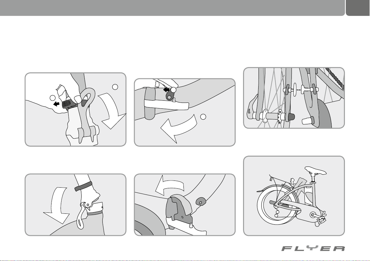
39
4. Open the safety on the handlebar stem
(black ring), at the bottom end, by turning it
anti-clockwise. Then press the lever down
und klappen Sie den Lenker-Vorbau auf die rechte Seite des Rades.
2
1
and fold the handlebar stem to the right side
of the bike.
5. If it is still out, fold the kickstand of your
FLYER back in.
6. First open the safety on the frame joint and
then push the lock lever back.
1
2
Then you can fold the front part of the frame
to the left.
7. Move the front and rear part of the frame together up to the point where the magnet holds
them in place.
8. This is how your FLYER should look in correctly folded position:
Page 44
40
Suspension frames and suspension-related parts
In order to unfold your FLYER folding bike, simply follow the instructions above in the reverse
order.
Please note the following:
• Lock lever and safety (point 7)
have to be correctly clicked into
place completely and securely.
• The lock lever (point 4) has to be totally upright in its final position and
completely covered by the safety.
• The stem (point 3) may only be pulled
out to the maximum length marking.
16. Bottom bracket and
cranks
Chain wheels are subject to wear due to their
constant use. Their functionality and life span
are influenced by:
• Maintenance and care
• Type of use and
• Number of kilometres ridden.
17. Checking the bottom
bracket
Pedal cranks which are not
completely secured can lead to
damage to the crankset. They
always have to be securely fastened.
• Check whether the bottom bracket is
secure at regular intervals by shaking
the cranks.
• If the cranks move in the bracket,
they have to be checked by a specialist retailer and secured.
Page 45
18. Wheels
41
18.1 Checking the wheels
The pedelec is connected to the ground by the
wheels. The wheels are subject to a great deal
of strain through the uneven characteristics of
the ground and the weight of the rider.
Thorough checks and centring work on the
wheels is undertaken before they are shipped.
However, during the first few kilometres of riding, the spokes bed in.
• After the first 100 kilometres, the wheels
have to be checked by a specialist and centred again if required.
• The tension of the spokes has to be checked
at regular intervals. Loose or damaged
spokes have to be replaced or centred by a
specialist retailer.
The wheels can be fixed in the frame and fork
in different ways. Commonly, the wheel is attached with an axle nut or a quick release. In
addition, there are also various thru axle connections which are screwed in or fixed with
various quick release systems. If a thru axle
is fitted on your pedelec, you can get more
information in the enclosed manufacturer operating manual or on the respective manufacturer’s website on the Internet.
All screws have to be tightened
with the correct torque. If the
torque is not correct, the screws
could break or loosen other parts (see
chapter 33.3 “Toques for screwed connections”).
18.2 Checking the hubs
You can check the hub bearings as follows:
• Lift the wheels up from the ground by first
lifting the pedelec at the front then at the
rear. Push each wheel to start them turning.
• The wheel should continue to turn and then
slow evenly. If the wheel suddenly stops, the
bearing is defective. One exception is front
wheels with a hub dynamo.
• The hub bearing should not exhibit play.
Pull the wheels in the front and rear fork
lightly to the sides to check if they are loose.
• If the wheels can be slightly moved in their
bearings or are difficult to turn, the hub
bearings have to be set up by a specialist
retailer.
18.3 Checking the rims
The rims will wear more quickly if the wheels
are fitted with rim brakes.
The stability of the rims will be
reduced if they are well worn.
This increases the vulnerability
to damage. A bent, cracked or broken
rim can cause serious accidents. Do not
continue to use your pedelec if you notice
damage on one of the rims. Please allow
a specialist retailer to check the rims.
Page 46
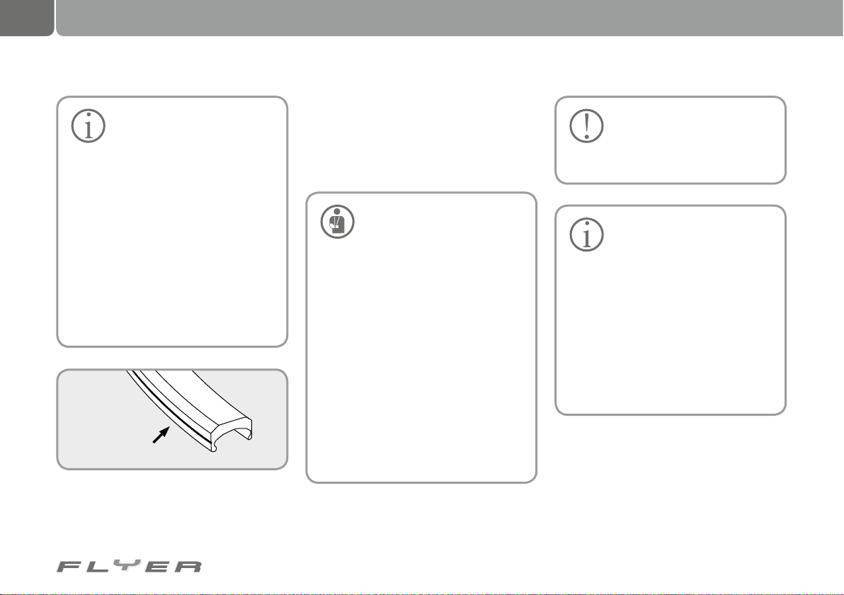
42
Wheels
19. Tyres and inner tubes
Modern rims from size 24” upwards have a marking which
shows rim wear. On the rim
surface there are coloured points or
grooves embossed which help you
gauge the level of wear.
If these markings are worn away or
no longer recognisable in one or more
places, the rim has to be replaced.
There are embossed markings which
disappear or colourful markings which
become visible if the rim has been used
for some time. If they appear, the rims
also have to be replaced. Please allow
a specialist retailer to check the rims at
the latest when you have worn out two
pairs of brake pads.
Grooves as a wear indicators
19.1 Tyres
Tyres are produced in different types. The tyre
profile differs from type to type. This governs
how effective the tyres are on different surfaces as well as the rolling friction.
The permitted tyre pressure
may not be exceeded when
inflating the tyres. Otherwise
this could lead to the danger of a tyre
exploding.
The tyres have to be pumped up with
at least the stated minimum tyre pressure. If the tyre pressure is too low,
there is a possibility that the tyre could
free itself from the rim.
On the side surface of the tyre, there
is information on the maximum permitted tyre pressure and generally also on
the minimum permitted tyre pressure.
If you replace the tyres, only exchange them for the same model with
the same dimensions and profile. The
bicycle’s handling could otherwise be
negatively affected. This can in turn result in accidents.
Tyres are subject to wear due
to their constant use. Check
the profile depth at regular intervals, as well as the tyre pressure and
condition of the side walls of the tyre.
Tyres are available in various
dimensions. The tyre dimen-
sions are stated with normed
information.
• Example 1: “46-622” states that the
tyres have a width of 46 mm and the
rim has a diameter of 622 mm
• Example 2: “28 x 1.60 inches” states
that the tyre has a diameter of 28
inches and a width of 1.60 inches
In general, air pressure is stated in the
unit PSI. A table for converting the air
pressure from PSI into bar is printed in
chapter 33.4 “Technical information”.
Page 47
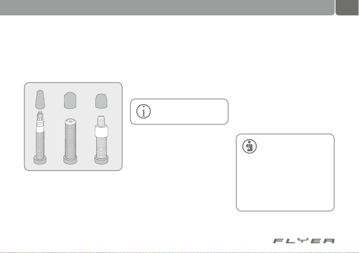
20. Dealing with a flat tyre
43
19.2 Inner tubes
The inner tube is the part of the bike which is
inflated with air. This is carried out via a valve.
Three different types of valve are used:
The Presta or Sclaverand valve
A valve cap is used in each of the three valve
types for preventing dirt from entering the
valve.
Use the following method to pump up an in-
ner tube fitted with a Presta or Sclaverand valve:
• Unscrew the valve cap by turning it anticlockwise.
• Open the knurled nut by turning it anticlockwise.
Schrader or American valve
Dunlop or Woods valve
• The valve is open if air escapes when you
place a small amount of pressure on the
knurled nut.
• Use a suitable air pump to inflate the inner
tube.
• Close the valve by turning the knurled nut
clockwise.
• Screw the valve cap onto the valve clockwise.
It is best to ask your specialist
retailer about which air pump is
suitable for your valve.
Use the following method to pump up an inner
tube fitted with a Dunlop or Woods valve:
• Unscrew the valve cap by turning it anticlockwise.
• Use a suitable air pump to inflate the inner
tube.
• Screw the valve cap onto the valve clockwise.
You require the following equipment for repairing a flat tyre:
• Tyre lever, plastic if possible
• Patch
• Rubber solution (patch adhesive)
• Sandpaper
• Possibly a replacement inner tube
• Possibly a replacement valve
• 15 mm open-ended spanner (if your FLYER
does not have any quick releases)
• A suitable air pump for the specific valve
It is best to first remove the wheel with the
flat tyre. To do this, remove or open the brakes
first. The specific process is dependent on the
type of brake system installed.
Please read the Brakes chapter
before opening the brakes. Do-
ing this incorrectly could damage the braking system and cause an
accident.
If you remove a wheel from a FLYER
with disc brakes, ensure that you place a
spacer in the brake caliper where the disc
usually fits. This ensures that the brake pistons are held in place and that no air can
enter the system. Do not apply the brake
lever until the wheel has been re-fitted.
Page 48
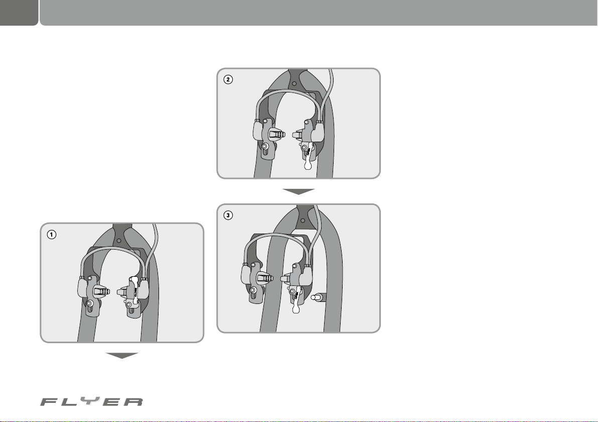
44
Dealing with a flat tyre
20.1 Opening a brake
20.1.1 Opening a V-brake
• Grip around the wheel with one hand.
• At the same time, press both brake arms
and brake pads against the rim at the same
time.
• The brake cable can now be removed on
one of the brake arms.
20.1.2 Opening hydraulic rim brakes
• If you have a brake quick release, you can
remove a braking unit
• Let the air out of the tyres if no brake quick
releases are fitted.
20.1.3 Loosening hub gears, roller or backpedal brakes
• Open the quick release on the brake arm or
the cable clamping screw.
• Open the screw on the brake arm on the
chain stay if you have backpedal brakes.
20.2 Removing a wheel
Please note that the process described in the
following is an example. Therefore please also
take note of the information provided by the
respective manufacturer or contact your specialist retailer.
20.2.1 Removing the front wheel
• You may have to remove the light cable before removing the wheel
• Open the quick release if your FLYER has
one (see chap. 7.2 “Operating quick releases”)
• If your front wheel is fixed with an axle nut,
loosen this anti-clockwise with a suitable
spanner (15 mm).
• If your front wheel is secured against unintentional removal by a specially shaped
dropout, turn the axle nut further in a clockwise direction. As soon as the washer and
axle nut no longer touch the dropout, you
can remove the front wheel from the fork.
• If your front wheel is fitted with a wheel re-
Page 49
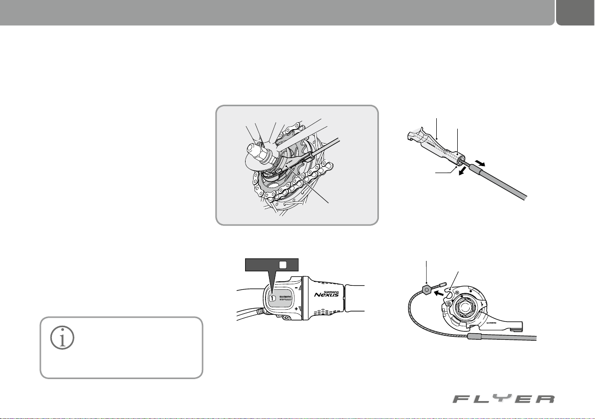
45
tention device, open the axle nut further by
turning it anti-clockwise.
• Push the wheel retention devices so far
apart that they no longer touch the dropouts
• Now remove the front wheel from the fork
20.2.2 Removing the rear wheel
With quick release:
• Change to the smallest sprocket on the rear
if your FLYER has chain gears. This makes
removing the rear wheel much easier as
the chain and therefore the rear derailleur
are relaxed.
• If your rear wheel is held in position by a
quick release, loosen this (see chap. 7.2
“Using quick releases”).
• Now lift the rear part of your FLYER slightly
with your left hand in order to free up the
rear wheel.
• Then give the rear wheel a gentle jolt from
above and then lightly towards the front.
• The wheel is then released and can be
threaded out of the chain.
Always lay your FLYER down on
the left hand side to ensure that
the gears are not subjected to
any weight. This is one of the most sensitive components on a pedelec.
With gear hubs:
• In order to remove the rear wheel, the cable
has to be removed from the shifter unit:
LOCK
0
2
S
8
-
J
C
N
A
P
A
J
Shifter unit
Step 1: Change the gear lever to position “1”
Switch to
1
Step 2: If you pull on the cable casing, you can
unthread the gear cable through the gap in the
counterholder of the gear unit.
Holder
Cable casing holder
C
J
-
8
S
2
0
J
A
P
A
N
Slot
Remove from
the slot
2
Pull out of the
cable casing
1
holder
Step 3: Remove the cable fastening screw from
the counterholder of the ratchet.
Cable fastening screw
Ratchet
L
O
C
K
CJ-8S20
JAPAN
Source: Shimano® techdocs
Page 50
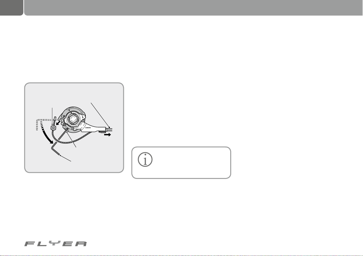
46
Dealing with a flat tyre
If there are problems removing the cable casing
from the counterholder of the shifter unit, insert
a 2 mm allen key or a #14 spoke into the ratchet.
By turning anti-clockwise, the gear cable is relaxed. First remove the cable fastening screw and
then the cable casing from the counterholder.
2
Remove
cable fastening
screw
1
Turn
ratchet
3
Pull from the cable casing holder
LOCK
CJ-8S20
JAPAN
Hole in the ratchet
2 mm allen key
or a #14 spoke
Source: Shimano® techdocs
Step 4: Loosen and remove the screw from
the brake arm fastener on the left chain stay
of your FLYER.
Step 5: Unscrew the axle nuts of the rear wheel
with a suitable spanner (15 mm) anti-clockwise.
Step 6: After removing the safety washers
from the hub axle, you can remove the rear
wheel from the rear fork of your pedelec.
20.3 Removing the tyre and inner tube
• Remove the valve cap and fastening nut
as well as possibly the cap nut from the
valve. Remove the valve stem from Dunlop
or Woods valves and keep this in as clean a
place as possible until it is reattached.
• Allow the remaining air to escape from the
inner tube.
In the case of a Presta valve (French valve), you
have to open this by turning and then pushing.
In the case of a Schrader valve, you can
help the remaining air to escape by pressing a
pointed object against the valve stem.
• Begin the process on the side opposite to
the valve on the inside edge of the wheel
with a suitable tyre lever.
Always work on the other side of
the bike to the gearside on the
rear wheel. This helps avoid any
possible injuries if you slip.
• To start with, lift the tyre wall over the edge
of the rim.
• Insert the second tyre lever approx. 10 cm
from the first one and lift another section of
tyre from the rim well.
• Repeat this process until the tyre has
been completely removed from the rim
on one side.
• Now you can remove the inner tube from
the tyre.
20.4 Patching an inner tube
• Pump the inner tube back up in order to be
able to identify where the inner tube is damaged. You may possibly have to remount the
valve stem (Dunlop or Woods valves).
• Ideally, you should be able to quickly identify the damaged spot by holding the inner
tube under water. The area in question can
be identified by the air bubbles escaping.
• If you are on a ride, you can pump the inner tube up very strongly. The high pressure
will mean that lots of air should be heard or
felt escaping from the problem area if you
hold the inner tube close to your face.
• In order to patch the tube, it has to be dry in
the damaged area.
• Now carefully roughen the damaged area
with sandpaper slightly on the inner tube.
• Apply the rubber solution as thinly and
evenly as possible around the leaky area.
• Allow the rubber solution to dry for several
minutes.
• Then press the rubber patch on the damaged area as firmly as possible and allow
this to dry for a few more minutes.
Page 51
47
20.5 Fitting a tyre and inner tube stalled tube into the middle of the rim. This
then slips to the base of the rim.
• After that, check that the valve is correctly
Before refitting the tyres, check
them for foreign bodies, such as
shards, thorns or nails, on the
outside and inside and remove anything
you find.
Ensure that no foreign bodies can en-
ter the inside of the tyre during fitting.
In addition, the inner tube should always be free of any folds, not twisted or
squashed.
Please also take note of the running
direction when fitting the tyre. This is
specified on the side of the tyre with a
recognisable arrow.
• To start with, please ensure that the rim
tape is intact and that all spoke holes are
covered.
• Pull one side of the tyre completely onto
the rim.
• Now thread the valve into the rim through
the valve hole.
• Assemble the valve if required and pump
the inner tube up somewhat until it has
gained its round shape.
• Place the inner tube completely within
the tyre.
• In order to be able to install the second side
of the tyre more easily, pull the already in-
positioned (sticking out from the rim as
straight as possible) and correct this if required.
• With both hands, pull the second side of the
tyre over the edge of the rim.
• Check again that the valve is correctly positioned and pump the tyre up slightly.
• You can use the control ring on the side of
the tyre to check that it is properly in place
and runs true. If it does not run round, correct this with jolting hand movements in the
area in question or across the entire tyre.
• You can subsequently pump the tyre back up
to the recommended tyre pressure. This is
specified on the side of the tyre in bar or PSI.
20.6 Fitting the wheels
Please note that the process described in the
following is an example.
Therefore please also take note of the in-
formation provided by the respective manufacturer or contact your specialist retailer.
20.6.1 Fitting the front wheel
When re-fitting the wheel, ensure that the front
wheel is fitted the right way around: The quick
release should be on the opposite side to the
chain system. Fit the wheel exactly in the mid-
dle of the dropout until it touches. When you
have tightened the axle nut or correctly closed
the quick release, you can then re-attach the
brake cable. Please ensure that the brake pads
are located correctly to meet the brake surfaces and then carry out a brake test.
If your FLYER has disc brakes,
ensure that the brake disc is
correctly located in the brake
caliper between the brake pads.
Page 52
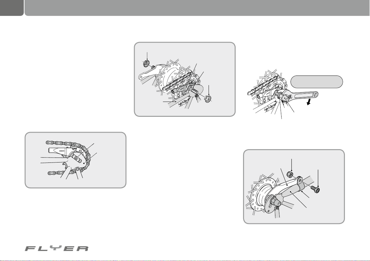
48
Dealing with a flat tyre
20.6.2 Fitting the rear wheel
20.6.2.1 FLYER with chain gears
Place the chain in the smallest sprocket.
Take the rear derailleur in your hand at the
parallelogram and pull it backwards.
Now pull the wheel into the dropouts until it
touches the end.
Close the quick release or tighten the wheel
nut with the required torque (see chapter 33.3).
20.6.2.2 FLYER with hub gears
Step 1: Place the chain on the sprocket and
thread the hub axle into both dropouts.
JAPAN
CJ-NX10
Hub axle
Dropout
Step 2: Attach the lock washers to both sides
of the hub axle. Turn the gearshift arm so that
the teeth of the lock washers mesh with the
slots in the dropouts. In this case the gearshift arm can be mounted almost parallel to
the frame fork.
Lock washer (left side)
Gear shift arm
Open side of
the dropout
Lock washer
(right side)
K
C
O
L
7R
Frame fork
J
A
P
A
N
C
J
-
N
X
1
0
• The protruding part of the lock washer has
to be located on the open side of the dropouts.
• Insert the lock washers in such a way that
the teeth precisely fit into the dropout slots
on the front and rear side of the hub axle.
Step 3: Tense the chain by pulling the rear wheel
backwards and attach this as centrally as possible in the rear fork with the axle nut using the
required torque.
Torque: 30 - 45 Nm
J
A
P
A
N
C
J
-
N
X
1
0
R
7
K
C
O
L
Cap nut
Lock washer
Step 4: Position the brake arm with its clamp
bracket correctly on the chain stay.
Clamp bracket nut
Brake arm
Clamp bracket screw
Brake arm
clamp bracket
Frame fork
Source: Shimano® techdocs
Page 53
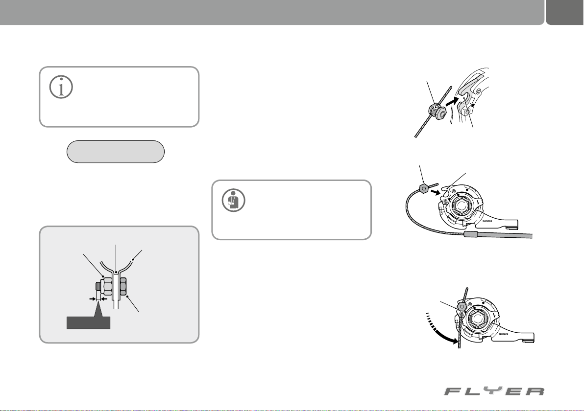
49
When fitting the brake arm
clamp bracket, hold the clamp
bracket nut tight with a 10 mm
spanner to tighten the clamp bracket
screw.
Torque: 2 - 3 Nm
After fitting the brake arm clamp bracket,
check that the clamp bracket screw protrudes
approximately 2 to 3 mm out of the clamp
bracket nut.
Brake arm
Clamp bracket nut
2 – 3 mm
Brake arm
clamp bracket
Clamp bracket
screw
(M6 x 16 mm)
Source: Shimano® techdocs
Step 5: Before using the backpedal brake,
check whether the brake is working correctly
and if the wheel can turn easily and freely.
• Reattach the brake cable (if required) or
close the brake quick release if your FLYER
has an additional brake.
• Check that the brake pads correctly contact the brake surfaces when applying the
brakes.
• Ensure that the brake arm is sufficiently
tightly secured.
Tighten all screws with the recommended torque. Otherwise,
parts could become loose or
screws could break (see chapter 33.3
“Torques for screwed connections”).
• Ensure that you carry out a brake test before you participate in public road traffic.
Fitting the shifter cable for hub gears:
Attach the cable to the cassette joint pulley
so that the cable attachment nut is pointed
outwards against the dropout and push the
straight side of the washer against the open
side of the pulley.
Straight side
of the washer
Cable attachment nut
Open side of the pulley
Cassette joint pulley
L
O
C
K
CJ-8S20
JAPAN
Turn the cable 60° to the right and fasten it on
the hook.
Hook
L
O
C
K
CJ-8S20
Turn 60°
JAPAN
Page 54
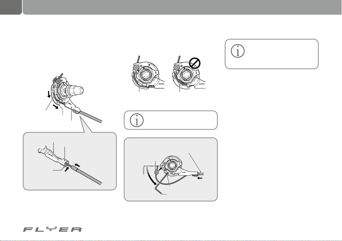
50
Dealing with a flat tyre
Attach the cable to the pulley as shown in the
diagram. Pull the cable through the slot in the
cassette joint bracket and plug the end of the cable casing securely into the cable casing holder.
LOCK
C
J
-8
S
2
0
J
A
P
A
N
Shifter cable
Cassette joint pulley
Bracket
Holder
Cable casing holder
1
Insert into
the cable
casing holder
2
C
J
-
8
S
2
0
J
A
P
A
N
Slot
Pass through
the slot
You can make this work easier for yourself by
first inserting the cable casing into the cable
casing holder, then sticking a 2 mm allen key
or a spoke into the hole in the pulley and turn-
ing the pulley in order to fit the cable fastening screw correctly in the open side.
L
O
C
K
CJ-8S20
JAPAN
Guide Guide
Correct Incorrect
L
O
C
K
CJ-8S20
JAPAN
Check if the cable is correctly
inserted in the pulley guides.
1
Insert into cable
casing holder
L
O
C
K
CJ-8S20
JAPAN
Pulley hole
2 mm allen key or #14 spoke
Source: Shimano® techdocs
Insert cable
attachment
screw
2
Turn pulley
3
You should only take part in public road traffic after first taking
your bike for a test ride and test-
ing your hub gear system.
Page 55
21. Bicycle gears
51
21.1 Chain gears
This operating manual describes the use of
common commercial gear components on a
pedelec as an example.
If your components are different, you will
find specific information in the respective operating manual or on the website of the manufacturer.
If you have any questions about assembling,
maintaining, setting up or operating the gears,
please contact your pedelec specialist retailer.
Using faulty, incorrectly set up
and worn gear components is
dangerous and can lead to falls.
Therefore if there is any uncertainty,
please have the gears checked by a specialist and set up again if required.
Contact your specialist retailer
if you have any of the following
problems:
• The chain comes off the sprockets or
the chain rings.
• Chain links, chain rings or sprockets
are broken or worn out.
• Changing gears does not work com-
pletely correctly.
• The rear derailleur or other gear shifting components appear to be damaged or loose.
• Unusual noises occur while changing
gear or riding.
Do not pedal backwards while
changing gears as this could
damage the gear system.
Changes to the setup of your gears
should only be made in small steps
and with the greatest of care. Incorrect
setup work can lead to the chain coming
off the sprockets and causing a fall. If
you are at all unsure, contact a specialist retailer who can set this up for you.
Despite a perfectly set up
chain gear system, a bike chain
crossing at an angle can lead to
noises during riding. These noises are
normal and do not cause any damage to
the gear components. With less angled
running of the chain in a different gear,
this noise will no longer appear.
The use of spoke guards is required. Otherwise, only minor
setup errors could lead to the
chain or the entire rear derailleur falling
between the sprockets and the spokes.
Therefore please always carefully switch into
the lowest gear or the largest rear sprocket if
you want to avoid damage.
Page 56
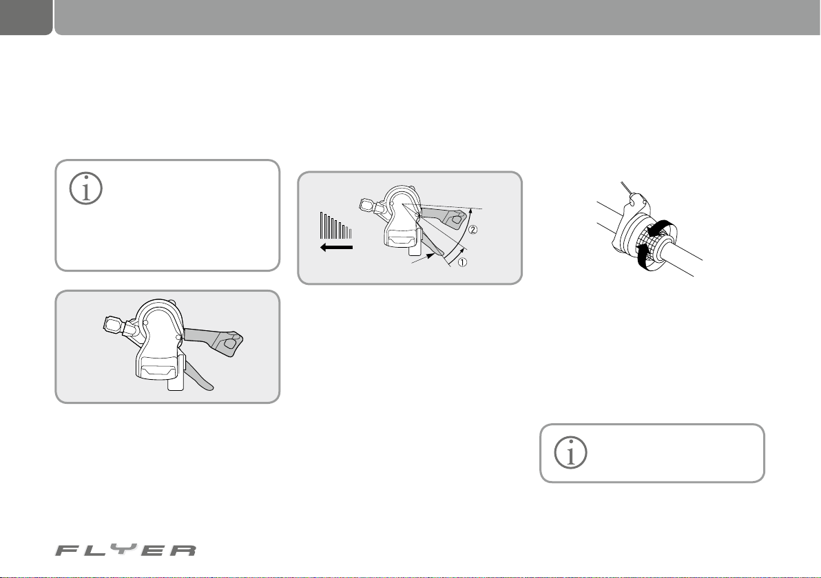
52
Bicycle gears
21.1.1 Operating the gears
21.1.1.1 Gear shift lever
Operating the gear shift lever, right:
The following description refers to the right 10x Shimano
XT gear shift lever for the rear
derailleur as an example. If your bicycle
features different components, please
inform yourself using the corresponding enclosing operating manual.
Lever A
Lever B
This gear shift lever has a two-way mechanism, meaning that it is possible to operate
it by both pushing and pulling. Both levers (A)
and (B) return to the starting position after
being applied. You have to continue pedalling
while applying the lever.
Switching from a small to a larger sprocket
(Lever A)
For switching just one gear, push lever (A) to
position (1). For switching two gears, push the
lever to position (2).
Lever (A) starting position
Source: Shimano® techdocs Source: Shimano® techdocs
Switching from a large to a smaller sprocket
(Lever B)
Applying this once will switch to a smaller gear.
21.1.1.2 Gear grip shift
By turning the gear grip shift, you can vary
the required amount of pedal force. If a gear
should be harder or lighter, you should turn the
grip shift one click in the desired direction.
Decreasing
pedal power
Increasing
pedal power
You can also switch through multiple gears at
the same time. To do this, push or pull through
multiple gear positions in the desired direction.
You do not necessarily have to continue
pedalling while applying the grip shift.
21.1.1.3 Gear settings for chain gears
Please have all servicing, replacement and setup work carried out by a specialist retailer.
Page 57
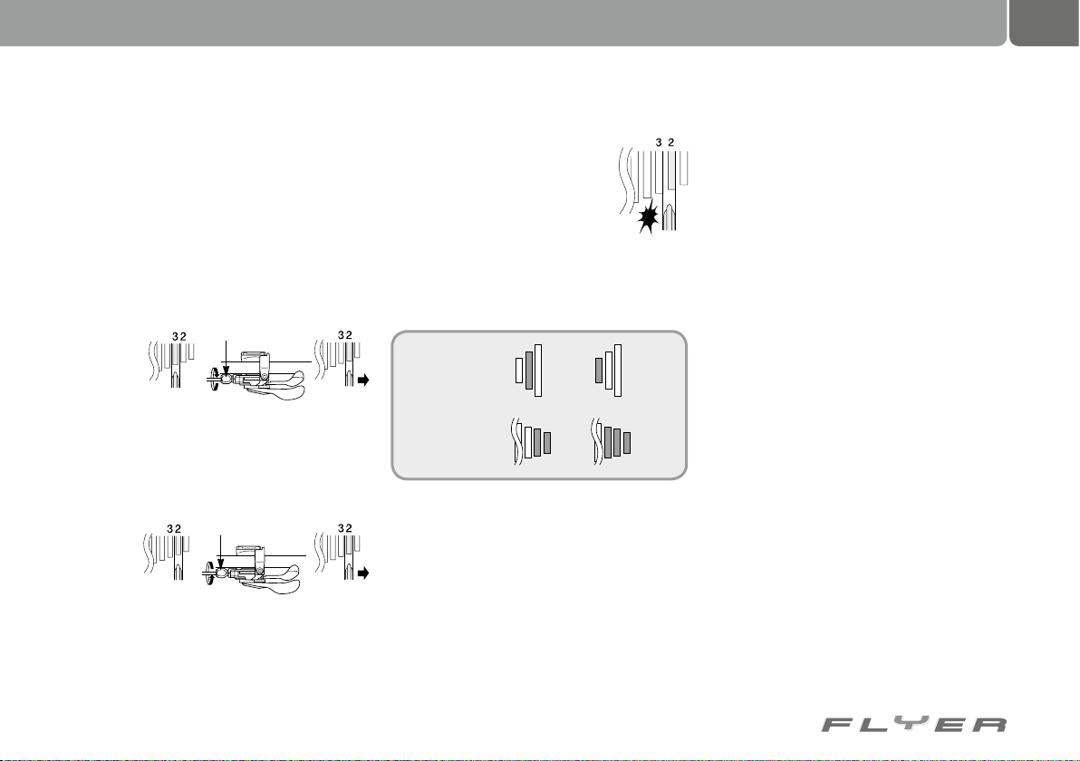
53
The following is an example of how to fine
tune a 10x Shimano XT rear derailleur. The
setup or process for a different rear derailleur is identical.
Fine tuning the rear derailleur:
Apply the gear shift lever once to switch the
chain from the smallest to the second sprocket. Then push the gear lever until you feel
some resistance and then turn the cranks.
If the chain
jumps onto
the third
sprocket
Adjustment screw
• Turn the adjustment screw on the gear lever to the right (clockwise) until the chain
jumps back onto the second sprocket.
Adjustment screw
If there are
no noises
• Loosen the adjustment screw so far to the
left (anti-clockwise) until the chain is grazing the third sprocket.
Fine tuning the shifting process:
When you feel resistance when
pressing the gear lever, the chain
should graze the third sprocket
and cause a noise.
If the chain grazes the third
sprocket, the adjusting screw has
to be turned to the right slightly until the grazing sound is no longer perceived.
To ensure smooth gear shifts, all force-bearing parts have to be greased.
Chain rings
Sprockets
Source: Shimano® techdocs
Cleaning and caring for your chain gear system:
• Sprockets and chain rings should be cleaned
with neutral fluid at regular intervals.
• The rear derailleur should be cleaned at
regular intervals and all moving parts, such
as the rollers, greased.
• The chain should not be cleaned with
grease-removing cleaning fluid. For instance, a rust-removal fluid can wash the
grease out of the chain. This could result
in problems operating the bike or premature wear.
Transporting a FLYER with chain gears:
If you want to transport your FLYER by car or
train, please ensure that the rear derailleur
is not subject to any pressure. Any pressure
could bend the attachment of the rear derailleur to the frame and lead to incorrect functionality. This can result in serious accidents if
the chain and the rear derailleur contact with
the spokes of the rear wheel.
If you remove the rear wheel for transport,
please ensure that the FLYER is lying on its left
side if possible, and that there is no pressure on
the rear derailleur (which should be facing up).
Page 58
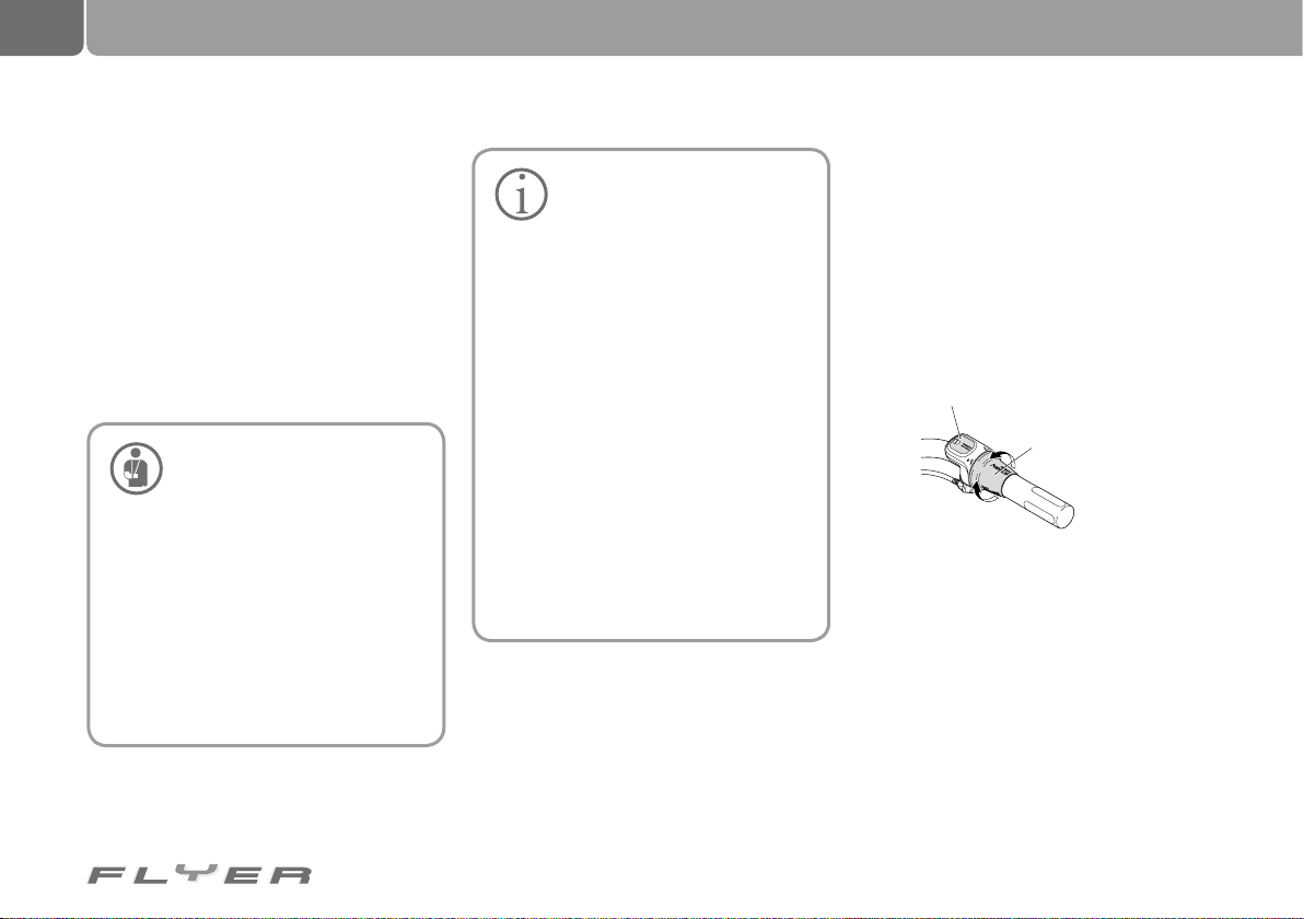
54
Bicycle gears
21.2 Hub gears
This operating manual describes the use of
common commercial gear components on a
pedelec as an example.
If your components are different, you will
find specific information in the respective
operating manual or on the website of the
manufacturer.
If you have any questions about assembling,
maintaining, setting up or operating the gears,
please contact your pedelec specialist retailer.
Ensure that the correct lock
washer is installed on both
sides of the hub and the axle nut
is screwed on with the correct torque
(see chap. 33.3 “Torques for screwed
connections”).
If only one lock washer is fitted or
the torque is incorrect, this can lead to
failure. This can cause the hub to twist
in the rear fork. It is possible that the
handlebars may be pulled in one direction as a result of the twisted gear cable. In turn, this could result in a serious
accident.
• If the rear wheel of your
FLYER is difficult to turn, the
brake shoes and/or the hub
likely have to be greased. This work
should be done by a specialist retailer.
• Gears can also be changed while you
are pedalling. Take a little pressure
off the pedals during gear changes.
Otherwise, depending on the additional motor performance, the internal excess load protection system of
the hub may prevent the gear change.
In exceptional cases this can also
cause gear changing noises within
the hub. These noises are harmless.
• The chain has to be immediately
checked or tensed if it comes off
the sprockets. You are required to
completely replace the sprocket/
chain ring if the entire adjustment
range of the rear wheel is maxed
out in the frame.
21.2.1 Operating hub gears
21.2.1.1 Shimano 7/8 gear grip shift
(Nexus/Alfine)
To change gear, turn the gear lever in the desired direction.
One turn towards the 1 results in less re-
quired pedal force, e.g. for uphill.
One turn towards the 7 results in more re-
quired pedal force, e.g. for downhill.
Display
Revo shift
lever
This gear concept from Shimano is generally
also applicable for the other manufacturers of
grip shift systems.
21.2.1.2 Shift lever 8/11 gear (Alfine)
The shift levers are equipped with the 2-WAY
RELEASE and MULTI RELEASE function, i.e.
with one movement two gears can be changed
and the lever can either be pushed or pulled.
Both levers (A) and (B) return to the starting
position after being applied.
Page 59
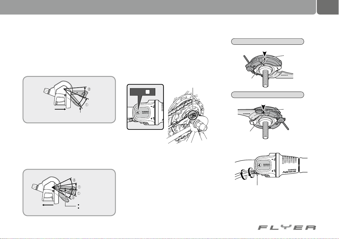
55
Switching into a lower gear (Lever A)
The number of gears switched is specified by
the lever stroke – for switching just one gear,
push lever (A) to position (1), or into position (2)
to switch two gears. In this way it is possible to
switch a maximum of two gears.
1611
Lever (A) starting position
Switching into a higher gear (Lever B)
The number of gears switched is specified by
the lever stroke – for switching just one gear,
push lever (A) to position (1), or into position (2)
to switch two gears. In this way it is possible to
switch a maximum of two gears.
1611
Lever (B) starting position
2-WAY RELEASE
MULTI RELEASE
21.2.2 Setting up Shimano hub gears
7 or 8 hear hubs.
• Switch the grip shift into position 4
• Check that the positioning of the yellow
marking on the holder matches that on the
ratchet.
Yellow marking lines
Set to
4
J
A
P
A
N
C
J
-
8
S
2
0
K
C
O
L
There are two clearly visible yellow markings
on two of the components.
If these yellow marking lines are not
aligned, turn the cable adjustment screw of
the gear lever to align the yellow markings. After this, set the gear lever from position 4 to 1
and then back to 4. Check if the yellow marking
lines are still aligned.
Bicycle in normal position
Aligned together
L
O
C
K
Bracket
Bicycle in reverse position
Aligned together
JAPAN
CJ-8S20
K
C
O
L
Bracket
Cable adjustment screw
Source: Shimano® techdocs
CJ-8S20
JAPAN
Pulley
Pulley
Page 60
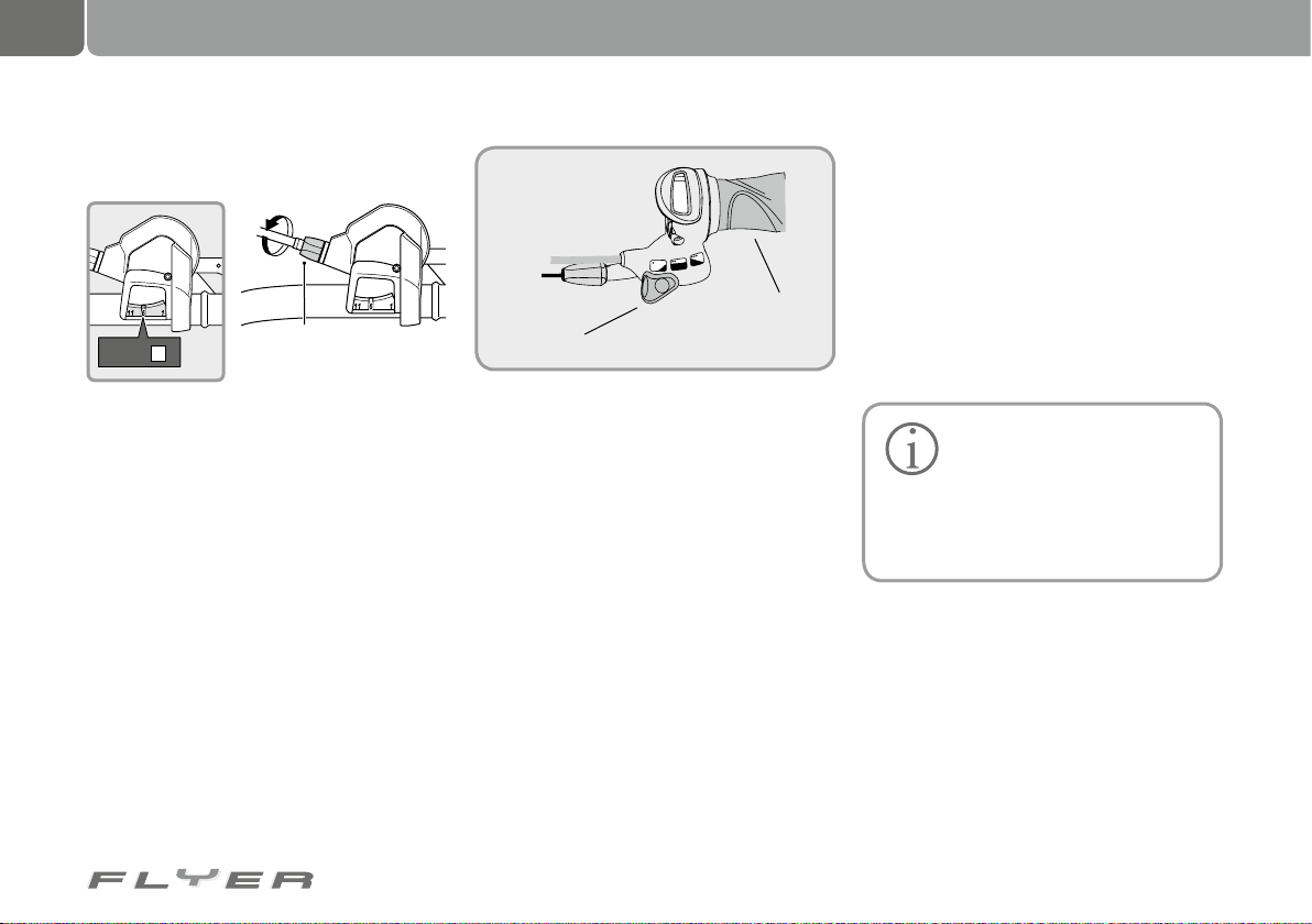
56
Bicycle gears
22. Bicycle chain
11 gear hub:
• Put the gear lever to position 6.
6
Set to
Otherwise the hub gears are set up in exactly
the same way as the 7/8 gear version.
Combination of hub and chain gear:
This type of gear system is offered by SRAM
under the name “Dual Drive”. This type of gear
system has a 3 gear hub and additional sprockets for conventional chain gear changes. One
of the advantages of this system is that there
is no need for a front derailleur and therefore
also little angled running of the chain.
The hub gear components are operated
with a thumb switcher and the chain gear system with a grip shifter or a trigger shifter in the
latest models.
The precise approach when setting up or removing/fitting the rear wheel is explained in the
enclosed instructions from the manufacturer.
Cable adjustment screw
Source: Shimano® techdocs
22.1 Bicycle chain maintenance
On a general level, you should know that there
are two different basic types of bicycle chain:
• Narrow chains which are used for chain
gear systems. The width of the chain varies
depending on the number of sprockets. You
Grip shift
Thumb shifter
Alternatively, the bike can also feature a 14
gear hub gear system from Rohloff or NuVinci
continuously variable gears, which are also
operated with a grip shift. The respective operating instructions as well as procedure for
removing/fitting the system in the case of a
puncture are provided in the enclosed operating instructions. It is certainly also helpful if
your specialist retailer explains the functionality to you and demonstrates removing/fitting
the system. How to check for wear on your bike chain:
should therefore only use chains which are
intended for your number of gears.
• Broad bicycle chains, (½ x 1/8”) which are
used for hub gear systems.
Regularly care for your bicycle chain by cleaning and
greasing it.
Attempt to ride in the gears with the
least angled running.
Both of these measures help prevent
premature wear.
• Hold some of the segments of the bike
chain on the front gear ring with the thumb
and forefinger.
• Attempt to lift the chain from the chain
ring. If there is a substantial gap between
the chain and ring, the chain is worn and
has to be replaced with a new one as soon
as possible.
Page 61
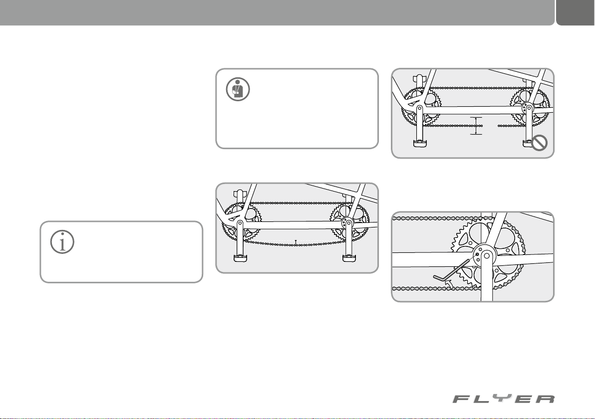
• Having the correct chain tension is very important for hub gear systems. There has to
be one to two centimetres of vertical play
between chain ring and sprockets.
Excessive play can lead to the chain falling off.
Too little play in contrast can lead to the chain
wearing prematurely.
Here is the basic approach to retightening
the bike chain:
• Loosen the axle nuts
• Pull the rear wheel backwards until the
chain has achieved the level of tension described.
• Carefully tighten all loosened screwed connections in a clockwise direction.
A worn bike chain can break and
cause very serious falls. For
this reason worn bicycle chains
should be immediately replaced by your
specialist retailer and not used on public roads before this work has been carried out.
22.2 Tensioning a tandem chain!
57
>3 cm
In this position, you should be able to move the
free chain by around 2 to 3 cm without the need
for much force.
Ensure you adhere to all prescribed torques. Otherwise,
parts could become loose or
break the screws (see chapter 33.3
“Torques for screwed connections”).
Bicycle chain maintenance:
Bike chains are parts which are typically subject to wear. They should be replaced at the following intervals.
• Hub gears: from approx. 3,000 km
• Chain gears: approx. 1,500-2,000 km
min
Turn the crankset into the position where the
tension of the chain is greatest or where the
chain sag is least.
If the tension of the chain is too high or too
low, the fixture of the bottom bracket eccentric
loosens.
In your FLYER Tandem, the eccentric is
clamped internally. The fixture is administered
by an allen key screw from the side.
Page 62
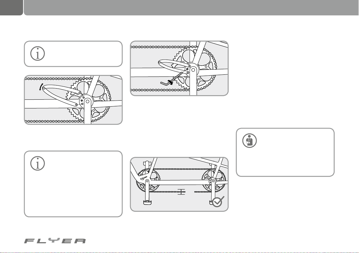
58
Bicycle chain
Only loosen this screw with two
or three turns anti-clockwise do not completely unscrew it!
Use a pin spanner to turn the eccentric until
the correct chain tension is achieved.
The correct chain tension is
achieved in two areas. Firstly,
the bottom bracket is located
over the central line of the eccentric
and below the central line of the eccentric. The first approach is better if the
seat cannot be set low enough or if additional ground clearance is required.
Otherwise, the second approach is more
recommended.
Finally, tighten the screws on the side of the
bottom bracket back with the correct torque.
You can find the correct torque for this in the
chapter 33.3 “Torques for screwed connections”.
While doing this, hold the eccentric tight
with a pin spanner, so that the eccentric does
not move while tightening the screw.
2-3 cm
Check the chain again for the correct tension.
23. Brakes, brake levers
and braking systems
In this operating manual, the servicing and
handling of the typical and commonly sold
brake components as featured in modern pedelecs are described. Your bicycle is supplied
with the correct operating manual for your
specific brake system. If you have any questions about the assembly, setup, servicing and
operation of this part of your bike, please contact a pedelec specialist retailer.
23.1 Important information and
precautionary measures
Maintenance work on the
brakes has to be undertaken by
a specialist.
No oil-based liquids should ever be
applied to brake pads, rim brake surfaces, brake shoes or brake discs. This
reduces the effectiveness of the brakes.
Brake pads and brake shoes are subject to
wear due to their constant use. You have to
check the level of wear at regular intervals.
Grooves on the brake shoes serve as markings
to help you to identify the level of wear. If these
are no longer visible, the brake shoes have to
be replaced. Always replace both brake shoes
at the same time.
Page 63
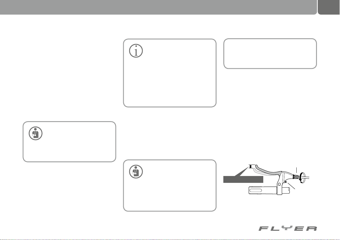
Only use original replacement parts. Otherwise it is possible that the functionality of
your pedelec is impacted or damage could be
caused.
Only use brake pads which match the rims,
as this is the only way to ensure that you have
the right friction combination.
If this is incorrect, the braking distance increases and there is higher wear.
On no account should you allow any oil or
grease to contact the brake pads, as the braking performance is otherwise substantially
impacted. If the brake pads come into contact
with oil or grease, these have to be replaced.
All screws have to be tightened
with the correct torque. If the
torque is not correct, the screws
could break or loosen other parts (see
chapter 33.3 “Torques for screwed connections”).
Brake cables are subject to wear
due to their constant use. Check
the wear level at regular intervals
and allow the brake cables to be replaced
by a specialist if required.
Regularly check the brake cable for
damage. If the cable is rusty or lacerated, have the cable replaced. If you do not
replace a brake cable in this condition, it
can negatively impact the effectiveness
of the brakes.
There are various braking systems which differ
depending on their areas of use:
• Hub brakes,
• Disk brakes and
• Rim brakes.
The brake systems can be operated mechanically or hydraulically.
Check the position of the
brake levers before your first
ride.
In hub gear systems, the right brake
lever on the handlebars is generally the
front brake. However, in chain gear systems, this brake lever is located on the
left side of the handlebars.
If you would like to swap the position
of the brake levers on the handlebars,
please contact a specialist retailer to do
the work.
23.2 Brake levers
23.2.1 Standard brake levers
Suitable brake levers are installed on your pedelec as standard. When you apply the brake
lever, you should not be able to pull it all the
way to the handlebar grip, even under heavy
braking. Regularly check the performance of
the brakes. The brake performance is no longer sufficient if you can roll your pedelec slightly
forwards under braking. In this case, the brake
cables have to be adjusted or the brake pads
replaced by a specialist retailer.
Cable adjustment screw
Play of approx. 15 mm
reach adjustment screw
Source: Shimano® techdocs
59
Page 64
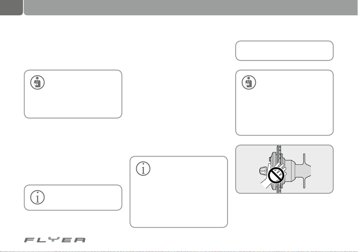
60
Bremstrommel
Brakes, brake levers and braking systems
23.3 Hub brakes
As the calipers are located in the hub, hub
brakes hardly require any servicing.
Hub brakes are strongly heated
by long periods of braking. Con-
stant braking can reduce the
braking performance, with the brakes
possibly completely failing. You should
therefore adjust your riding style accordingly.
23.3.1 Roller brakes
The braking force of roller brakes is applied
via a cable pull from the brake lever to the
brakes. Longer periods of braking strongly
heat roller brakes. Constant braking can
reduce the braking performance, with the
brakes possibly completely failing. You should
therefore adjust your riding style accordingly.
The brake lever has to be
specially adjusted for roller
brakes.
• Check that the screws on the brake lever
are secure at regular intervals.
• By turning the screws clockwise, you can
tighten these. Please adhere to the correct torque (see chapter 33.3 “Torques for
screwed connections”).
• Check the performance of the brakes by
pushing the pedelec forwards and applying
the front and rear brake levers in succession, just as you would during strong periods of braking. If the brakes are working
correctly, the front brake should brake so
effectively that the rear wheel lifts off the
ground. The braking force on the rear wheel
should be so strong that the wheel locks.
• Oil the pull cable at regular intervals.
• Have the brake oiled with Shimano roller
brake grease from Shimano at regular
intervals.
Brake pads are subject to wear
due to their constant use. Have
the brake pads in all braking
systems checked and if required replaced by a specialist retailer at regular
intervals.
After the bike has stood for a period of time, a rust film can form on the
brakes, which increases the braking
effect. When beginning your ride, you
should brake lightly multiple times to
remove the rust film. This avoids the
brakes suddenly blocking.
Do not brake constantly on long
downhill sections, otherwise
the brakes can become very
hot, which can reduce their effectiveness. Alternate between applying the
front and back brake on long and steep
downhill sections to allow the other
brake to cool. Do not touch the brakes
for at least 30 minutes after riding as
they can become very hot.
Source: Shimano® techdocs
Page 65
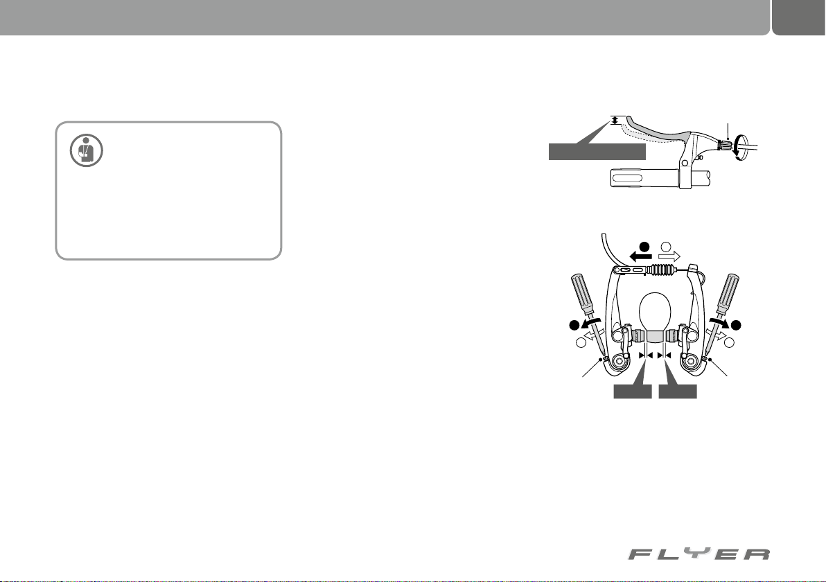
61
23.4 Rim brakes (V-brakes)
The braking performance of
modern rim brakes is very
strong. You have to get used
to the braking performance of the Vbrakes. Only apply the brakes in doses.
You have to practice making emergency
stops so that you are able to safely manoeuvre your pedelec during very strong
braking manoeuvres.
If improper additional parts are used in the
braking system (power modulators), this can
cause serious falls. When using power modulators, the required spring force depends on
the total weight of the pedelec.
23.4.1 Adjusting brakes
Your FLYER will be handed over to you by your
retailer correctly set up. There should be a gap
of 1-1.5 mm on either side between the brake
shoes and the rim. As the brake shoes wear,
the gap grows over time, which increases the
amount you are required to pull the brake lever. You should therefore check the brake at
regular intervals and make adjustments if the
lever distance is too large or the brakes are not
working correctly.
You can identify the wear level of the brake
shoes from the notches on the shoes. If these
are no longer visible, the brake shoes have to
be replaced by a specialist retailer.
Test the functionality of the brakes as follows:
• Check the performance of the brakes by
pushing the pedelec forwards and applying
the front and rear brake levers in succession, just as you would during strong periods of braking.
• The front brake should brake so effectively
that the rear wheel lifts off the ground.
• The braking force on the rear wheel should
be so strong that it locks.
23.4.2 Setting the distance of the brake pad
to the rim
The distance between the brake pad and the
rim can be set by turning the cable adjustment
screw on the brake lever. If you turn the adjustment screw inwards and clockwise, you can
increase the distance between the brake pad
and rim. If you turn the adjustment screw outwards and anti-clockwise, you can reduce the
distance between the brake pad and rim. There
should be a distance of approx. 1 mm between
the brake shoes and the rim.
Setting the pull cable
Cable adjustment screw
Play of approx. 15 mm
Cable adjustment screw
2
1
2
1
Spring adjustment screw
Setting up the distance between the brakes and the rim
1 mm
1 mm
Source: Shimano® techdocs
2
1
Spring adjustment screw
Page 66
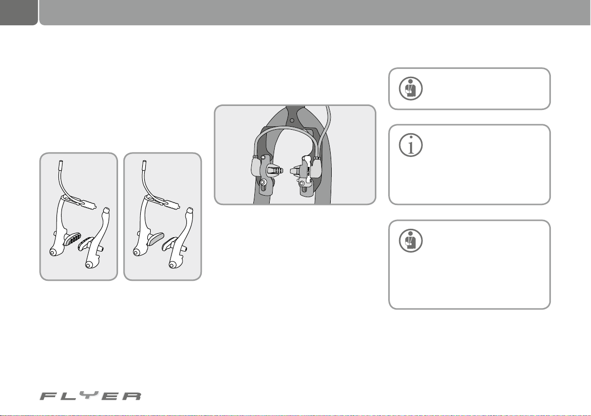
62
Brakes, brake levers and braking systems
23.4.3 Brake pad wear
The brake pads for rim brakes are almost all fitted with grooves or notches.
The grooves and notches serve in part to
help identify the wear level of the brake pads.
If these can no longer be seen, you should replace the brake pad.
New brake pads Worn out brake pad
If a brake pad is grazing against the rim:
The spring setting allows you to set the return force in such a way that both brake pads
lift evenly from the rim when you release the
brake lever. Subsequently check that the
brakes are working correctly (see chapter
23.4.1 “Adjusting brakes”).
23.4.4 Hydraulic rim brakes
Magura HS 33 hydraulic rim brakes:
To remove the front or rear wheel, the quick release lever of the brakes first has to be opened.
To do this, it first has to be opened downwards,
so that the lettering “OPEN” can be seen. Now
remove the loosened brake unit from the brake
boss by pulling it from its positioning. When
subsequently removing the wheel, you now
have enough space to remove the tyre.
Re-fitting the wheel is the same process as
removing the wheel, simply in reverse. Before
you close the brake quick release, the brake
has to be positioned in such a way that the
brake pad contacts the middle of the rim when
the brake is applied. Ensure that the word
“CLOSED” can be seen on the closed quick release lever.
Also ensure that you at least carry out a test braking before you
participate in public road traffic.
Have the brake fluid replaced
on a regular basis. Check the
brake shoes regularly and have
them replaced when they are worn out.
You can get more information in
the manufacturer’s operating instructions and at www.magura.com
Have your pedelec checked by a
specialist retailer if the brakes
are not working correctly. If
your brake pads are so heavily worn that
it is no longer posisble to readjust them,
do not continue to use your pedelec.
First have the brake pads replaced by a
specialist retailer.
Page 67
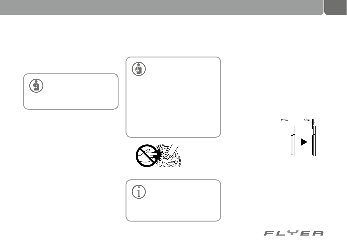
63
23.5 Disc brakes
In the case of disc brakes, the brake discs are
located on the hub and the brake caliper on the
frame or on the fork.
Setting up and servicing disc
brakes has to be done by spe-
cialist retailer. Incorrectly set
up brakes can cause accidents and serious injuries.
It is essential to test the brakes every time you
change the brake setup. To do this, pull on the
brake lever and push the pedelec strongly forwards. Only ride your pedelec if you are able to
safely stop it.
In the case of disc brakes, some time is re-
quired to wear in the discs and pads. The braking system only delivers its full performance
after around 10 braking cycles from 30 km/h.
The braking force increases during this time.
Consider this during the entire duration of the
wearing-in period.
This wearing-in period is also required after
replacing the brake pads or disks.
Pay attention to any unusual noise when
braking, as this could be a sign that the brake
pads have worn down to the wear limit. Please
check the thickness of the brake pads after the
brakes cool down. If required, you have to have
the brake pads replaced.
Please do not touch the brake
disc while it is rotating. Pay
attention to this when fitting,
removing and servicing the brakes. You
can suffer serious injuries if your finger is caught in the gaps of a rotating
disc brake.
The brake caliper and disc can heat up
during braking. You could suffer burns if
you touch this part during or directly after braking. Only set the brakes up after
you have ensured that the parts are sufficiently cooled.
Source: Shimano® techdocs
You may only fit a disc brake
system on your pedelec if the
corresponding fittings for attaching it to the frame and fork are already available. If you are unsure, ask a
specialist retailer.
Ensure you have the brake pads replaced
if they are tainted with oil or grease. Clean
the brake disc with isopropyl alcohol if oil or
grease gets onto the disk, otherwise the braking performance will be considerably reduced.
The quick release lever for the wheel has to
be installed on the opposite side to the brake
disc. Otherwise you could suffer burns from the
brake disk when operating the lever. The clamping force of the quick release can be reduced if it
is heated by the brake disk.
Have the brake disk replaced if it is worn out
or bent. This replacement procedure has to be
carried out by a specialist retailer.
If the remaining
thickness of the brake
pads is less than 0.5
mm, these have to be
replaced. As this is a
vital part for your safety,
this work should be carried out by a specialist
retailer.
New: 2 mm
Worn: 0.5 mm
23.5.1 Hydraulic disc brakes
There is a master cylinder on the brake lever of
the hydraulic disk drakes. The hydraulic fluid is
connected to the braking cylinders via a tube
and the brake pads are pressed against the
brake discs via brake pistons. Hydraulic disc
brakes can have a strong braking effect. This
type of brake does not require much servicing.
Page 68
64
Brakes, brake levers and braking systems
It is essential to test the brakes
every time you change the brake
setup. To do this, pull on the
brake lever and push the pedelec strongly forwards. Only ride your pedelec if you
are able to safely stop it.
It is possible that brake fluid can escape from
the system due to leaky cables and connections. This can negatively impact the effectiveness of the brakes. Before every ride you
should therefore check whether the cables and
connections are leaking at all.
Do not ride with your FLYER if fluid is es-
caping from the braking system. Please allow
a specialist retailer to undertake repair work
on this part immediately. The danger of your
brakes failing in this condition is very high.
You may NOT ride either if the brake pads
or disc/rim are tainted with grease. Dirty pads
have to be replaced, greasy rims and brake
discs have to be cleaned.
23.5.2 Formation of vapour bubbles
Avoid permanently braking for long periods, as
can be the case during long, steep descents. A
better approach is alternating between using
the front and back brake, as this allows each
brake to cool in sequence. Brake directly before sections where you have to ride slowly.
This helps you to avoid overheating the
brakes. If the brakes are heated over the boiling point, vapour bubbles can be caused which
will in turn cause a total failure of the braking
system, as no braking pressure can be built up.
Ensure that the brake lever is
not applied when your FLYER is
being transported on its side or
upside down. Otherwise air bubbles can
enter the hydraulic system which could
cause the brakes to fail. After transporting the bicycle, check if the pressure
point of the brakes seems different than
it was before.
If the brakes feel softer than before,
apply the brakes slowly several times.
This allows the braking system to discharge any bubbles. If the brakes remain
soft, please refrain from riding. A specialist retailer has to discharge the air
from the brake system.
You can avoid this problem by
applying the brake lever before
transport and then fixing it in
this position using a strap or a rubber
band. This prevents any air from entering the hydraulic system.
23.5.3 Cleaning the brakes
When you come to cleaning the braking system, please first read the instructions provided
by the component manufacturer. The braking
system can be cleaned in the same way as
the rest of the bike with warm water and mild
cleaning fluid, e.g. washing up liquid. You can
use a sponge or a soft cloth.
The brake discs and brake surfaces of rims
should be specially cleaned with isopropyl alcohol. Your FLYER retailer can recommend a
suitable cleaning fluid for this.
In particular, brake pads are
subject to wear. Please allow a
FLYER retailer to check these
key parts on a regular basis and replace
any worn parts if necessary.
Page 69
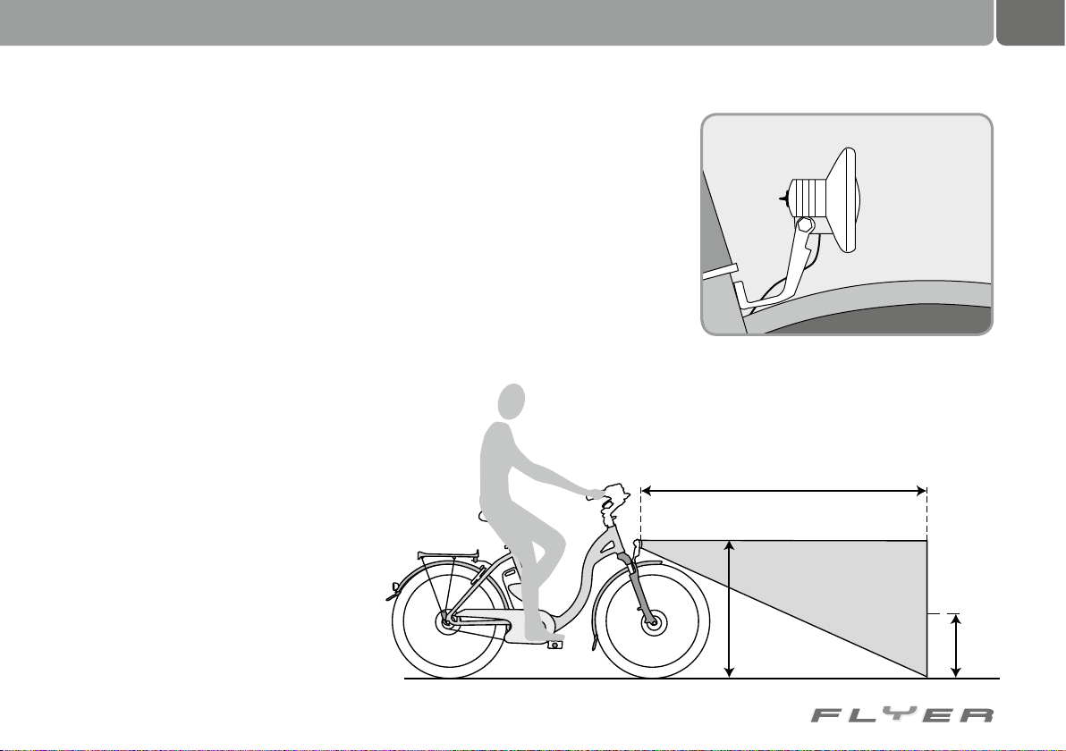
24. Lighting systems
65
23.5.4 Fitting/removing wheels
• If you remove a wheel from your FLYER
for transport, e.g. in a car, ensure that you
place a spacer in the brake caliper where
the disk usually fits. This ensures that the
brake pistons are held in place and that no
air can enter the system.
• If the brake pistons were pushed so far
out during transport that the disc brake no
longer fits between them, both pistons have
to be carefully and equally pushed back. To
do this, push a flat and CLEAN object between both brake pads – this could be a
tyre lever or a grease-free tool. Use this to
press the brake piston back into its starting
position. Fit the wheel and stand the bike
up. Now apply the brake lever several times
until the brake pads contact the brake disc
as usual and then return to the correct position when you release the lever.
• Fit the quick release of the wheel in such
a way that the quick release lever is on
the side of the bike where there is no disc
brake. The heat which is generated by using
the brakes can have the effect of loosening
the quick release. This could result in serious falls and injury.
24.1 Lighting system regulations
The front headlight has to be pointing in the
direction to illuminate the road five metres in
front of you.
e.g. 1m
5m
0,5m
Page 70
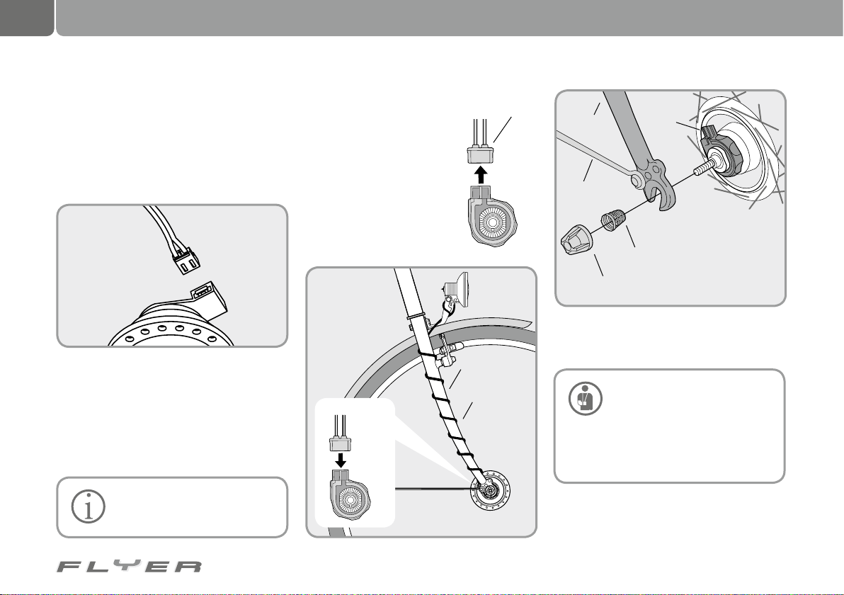
66
Lighting systems
24.2 Dynamo
The dynamo generates the required electrical energy for the front headlight and the rear
lights.
24.2.1 Hub dynamo
If your FLYER uses a hub dynamo, you can
switch this on and off easily on the rear side
of your front headlight with the on/off switch.
If the lighting system of your bike is equipped
with a light sensor, the dynamo will automatically switch on or off.
In order to remove the front
wheel, you first have to remove
the connection of the light cable.
To refit the light cable, the
connecting terminal of the
hub dynamo has to be fitted on the right (facing
forwards). Re-attach the
connections correctly and
check that the lighting is
working properly. To do this,
turn the front wheel and
check if the light comes on.
Connector cover
Connect
Connector cover
Remove
Front wheel fork
Cable
Front
wheel
fork
Mudguard stay
Quick release nut
Connecting
terminal
Spiral spring
Source: Shimano® techdocs
24.3 Failure of the lighting system
The lighting system is a key part
and it is vital that it is proper
working condition! Only have
check-up and servicing work done by
authorised specialist retailers after failures or temporary problems!
Page 71
25. Additional parts
67
Carefully read the operating
manual of your lighting system.
If there are any errors in the
functionality, you can simply replace the
bulbs in conventional headlights. To do
this, you have to have basic DIY skills!
You can purchase the correct bulbs at
your specialist retailer. Modern headlights are equipped with LED technology,
however this often means that the bulbs
cannot be replaced . In the case of a defect, the entire lamp has to be replaced!
Clean the reflectors and head-
lights of the lighting system at
regular intervals! Warm water
and washing up liquid suffice for this
job. Keep contact points clean and conductive with a suitable maintenance oil!
Your FLYER is fitted with modern
lighting technology. In addition to the
conventional features, it also offers you
safety functions such as a standlight.
This means that if you are stationary
at night, e.g. at a traffic light, you are
still visible to other public road traffic participants. Equally, some models
are equipped with the newly developed
daytime lights. These are supplied by
various energy sources depending on
the riding situation. For more on this,
please read the instructions supplied by
the component manufacturer.
25.1 Luggage rack
If you are riding with luggage,
ensure that you do not exceed
the maximum permissible
weight of the bicycle (you can get information on this in chapter 33.1, “Technical information”). The permitted load
of the luggage rack is either printed on
the product itself or can be derived online or from the specialist retailer.
Luggage load changes the behav-
iour of your pedelec. Not only is
the braking distance lengthened
with more weight, the steering is also less
responsive. You should therefore adjust
your riding style to the braking and steering behaviour of your FLYER, and always
anticipate a longer braking distance! Only
transport luggage on purpose-designed
luggage racks and do not exceed the maximum permitted load! Never attach a luggage rack to the seat post, as the latter is
not designed for this purpose. This could
result in part failure and serious falls. You
invalidate your warranty from the manufacturer by fitting a luggage rack to a seat
post not intended for this purpose.
Page 72
68
Additional parts
25.1.1 Front wheel rack
Luggage racks can be fixed to
the front wheel axle or the fork.
Note that this type of front wheel
rack strongly impacts the handling of the
bike. Practice riding with a loaded front
wheel rack on an open, quiet car park or
in a quiet area. If you are riding with a
suspension fork, the suspension/shock
absorber of the fork has to be adjusted
to the substantial load of the front wheel
rack. For more on this, please read the
instructions supplied by the component
manufacturer.
25.1.2 Rear luggage rack
On a full-suspension frame,
mounting a luggage rack to-
gether with the additional load
can substantially alter the handling and
suspension of the bike. The suspension/
shock absorber therefore has to be adjusted to the load. To do this, ensure that
you follow the operating manual of the
rear suspension supplied with the bike.
When transporting panniers or
other loads, ensure that they
are reliably and safely attached.
Ensure that no parts can get hooked in
the spokes or the turning wheels.
You are only permitted to install
a child seat if the corresponding
holders for such a seat exist on
the luggage rack. Please also take the
maximum permitted load of the luggage
rack as well as that of the pedelec into
account (see chap. 33.1 “Technical information”).
25.2 Mudguard
Mudguards are fixed correctly in place with special
braces. If the inside of the mudguard runs parallel to the tyre forming a ring shape, the braces are
perfectly positioned.
During normal use, the mudguard should
not loosen. In the case that an object becomes
jammed between the mudguard and the tyre,
the mudguard is fitted with a safety fastening.
This releases the mudguard from its holder to
prevent a fall.
You have to stop riding immediately if a foreign body is
trapped between the tyre and
the mudguard. The foreign body has to
be removed before you can continue on
your ride. Otherwise, there could be a
risk of a fall and serious injuries.
On no account should you con-
tinue riding with a loose mud-
guard brace, as this could become wedged in the wheel and jam it.
Damaged mudguards have to be replaced
by a specialist retailer before riding again.
In addition, you should also regularly check
whether the braces are fixed securely in the
safety releases.
Page 73
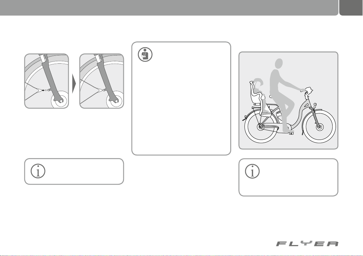
26. Accessories and equipment
69
25.2.1 Re-locking a safety release 26.1 Child seat
The diagram features a brace attached with a
plastic clip.
• This clip is locked into the easy-clip stay on
the fork.
• The mudguards are aligned in such a way
that they do not contact the tyres.
It is not unusual for re-locking
a clip connection to require a
great deal of force.
You always have to fit the enclosed accessories in line with
the guidelines and instructions.
You have to ensure that screwed connections are secured with the correct
torque (see chapter 33.3 “Torques for
screwed connections”).
• Only use add-on parts which satisfy
the requirements of the applicable
legal guidelines and road traffic regulations.
• Using unpermitted add-ons can re-
sult in accidents. You should therefore only use original accessories and
add-on parts which fit your pedelec.
• Otherwise this can lead to accidents
or damage on the pedelec. Allow a
specialist retailer to advise you.
In Germany and Austria (up to
the age of 7 years) and in Swit-
zerland, children may be transported on a safe child seat, provided
that the driver is at least 16 years old.
Page 74
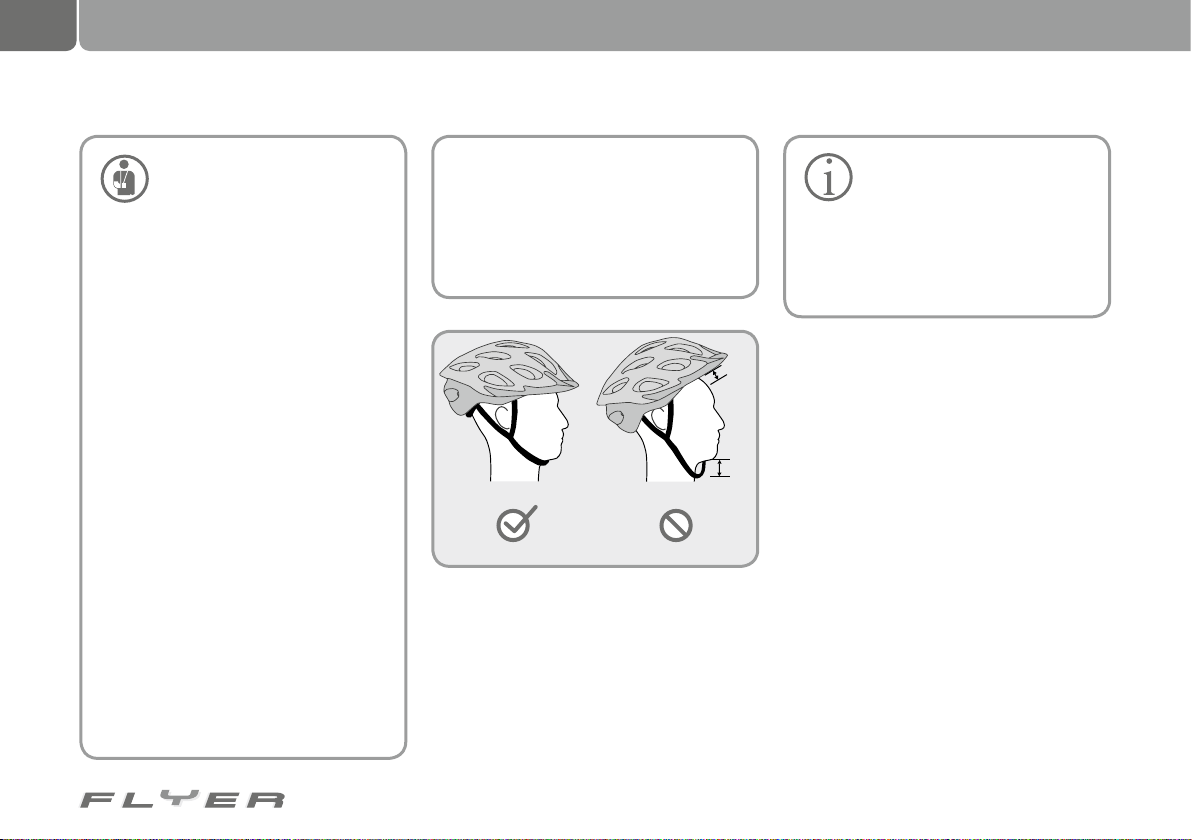
70
Accessories and equipment
A child seat may not be fitted to
a pedelec with a carbon frame,
otherwise it can be damaged.
• Only use child seats which correspond with the applicable legal requirements, which is norm EN 14344
in Germany. Using unpermitted child
seats can lead to serious falls and
injuries.
• Ensure that the child’s feet are supported in the child seat.
• You should never leave children in the
child seat of a parked pedelec unattended. If the pedelec falls over, the
child can be seriously injured.
• The child seat cannot be directly attached to the handlebars. Otherwise
you will no longer be able to safely
steer the pedelec.
• If you transport a child in a child seat
located behind the rider’s seat, do not
use a suspension seat. The child can
trap its fingers in this system. You can
prevent a child from getting its fingers between the winds of the spiral
suspension by completely covering
the springs under the seat. The same
applies for parallelogram seat posts!
The moving levers of the suspension
seat posts are dangerous! Prevent
the child from reaching into this part.
• The child always has to be strapped
into the child seat. Otherwise there is
a danger of the child falling out and
being seriously injured.
• Children should always wear a wellfitting bicycle helmet in order to prevent head injuries in the case of a fall.
The handling of the pedelec is
negatively impacted by riding
with a child seat. The additional
weight can lead to the pedelec lurching from side to side. You also require
a substantially longer braking distance
to stop. You should therefore adjust your
riding style accordingly.
It is not possible to fit a child seat to all pedelecs.
Check if it is possible to fit a child seat or
ask a specialist retailer. Serious accidents can
result from the child seat being incorrectly fitted or installed on unsuitable frames.
The maximum permitted total weight of the
pedelec and the maximum load of the luggage
rack may not be exceeded when transporting
children in a child seat (see chap. 33.1 “Technical information”). Otherwise there is a danger
of damage to luggage rack and frame as well
as the possibility of serious accidents.
Page 75
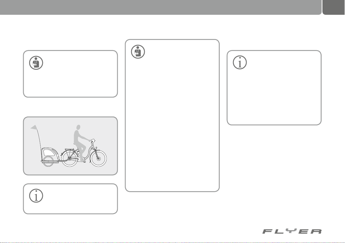
71
26.2 Kickstand 26.4 Basket
• Only use trailers which satisfy the requirements of the
• You should never leave
children in the child seat of a
parked pedelec unattended. If
the pedelec falls over, the child can
be seriously injured.
• Before every ride, please fold the
kickstand back in.
26.3 Bike trailer
Please inform yourself about
the applicable national guidelines before you use a trailer,
e.g. to transport children!
applicable national legal guidelines. Using unpermitted trailers can
lead to serious falls and injuries.
• The handling of the pedelec is negatively influenced by using a trailer.
You should therefore adjust your riding style accordingly. Otherwise there
is a danger that the trailer could flip
over or come off, which can lead to
very serious falls and accidents.
• Practice setting off, braking, riding
around corners and on hills in a safe
place with an empty trailer.
• The weight of the trailer is also included in the calculation for the highest permissible overall weight.
• You may require a substantially longer braking distance to stop when riding with a trailer. Please take this into
account in order to avoid accidents.
• Ask your specialised dealer about
the maximum permissible weight
of the trailer you may tow with your
Flyer.
The handlebars or stem may
not be damaged by attaching
the basket.
• The basket may neither cover headlights nor front reflectors.
• The brake and gear cables may not
be folded or restricted in their movement by attaching the basket.
• The basket can carry a maximum
load of five kilograms.
• Please note that a basket can influence the handling of the bike.
Page 76
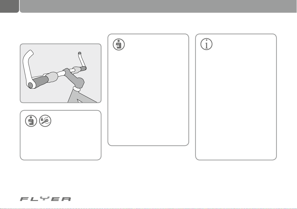
72
Accessories and equipment
27. Car roof rack and rear carrier
26.5 Bar ends
Bar ends always have to
be attached to the han-
dlebars with the correct
torque, otherwise this can cause falls.
Before fitting the bar ends, please inform yourself whether the add-on has
been approved by the handlebar manufacturer, as only then may the bar ends
be fitted.
• Only use rear carries which
satisfy the requirements of the
applicable national legislation
for transporting your bike by car. Using unpermitted rear carriers can result in accidents.
• Adjust your driving according to the
weight of your rear carrier.
Check that the pedelec is properly fastened at regular intervals during transport. If your pedelec falls out of the
carrier, it can cause serious accidents.
Please note that loose parts, such
as tools, luggage and tool bags, child
seats, air pumps etc. could fall off during transport. Other road traffic participants could be endangered by this,
so you should remove all loose parts
from the pedelec before beginning
transport.
A roof rack changes the total height
of your vehicle.
• Do not transport your pedelec upside down. Only secure
the pedelec on the handlebars
stem, seat or seat post if this is intended by the manufacturer of the
carrier. When securing the bike, ensure that no damage is caused to the
fork or the frame.
• You may not attach your pedelec to
the roof rack or rear carrier by its
crankset. The pedelec always has
to be transported standing on its
wheels. The only exception to this
is if the carrier stipulates a different type of transport. Not adhering
to this could cause damage to the
frame and fork.
• When transporting the pedelec by
car, the battery has to be removed
and transported separately.
Inform yourself online on the website
of the respective manufacturers about
assembling and using add-on parts and
accessories for your pedelec. A list of
links is printed in chapter 31.
Page 77
28. Carbon components
73
As a special material, carbon (carbon fibre)
requires special handling and care. This
applies for the design of the pedelec, the
maintenance, the riding style as well as the
transport and storage.
28.1 Properties
Carbon parts may not be bent,
dented or misshapen after an
accident or fall. Fibres could
be destroyed in some cases or have
loosened without being visible from the
outside. Carbon parts can already
Ensure you very carefully check the carbon
frame for damage after a fall or an accident
involving your carbon FLYER. If you are not absolutely certain that the frame is undamaged,
please have the bike checked by a specialist.
28.2 Torques
The torque for securely
fastening carbon com-
ponents on the carbon
frame can be lower than metal components. If the torques are too high, this
can lead to hidden damage which can-
not be identified from the outside. It can
cause the frame to break or change,
which could in turn cause falls. You
therefore always have to adhere to the
enclosed information from the manufacturer or ask a specialist. Always use
a torque spanner to fit parts with the
correct torque.
28.3 Visual checks
be damaged from past falls.
These parts could suddenly
fail and trigger serious accidents.
That is why carbon add-on parts as
well as carbon frames should be thoroughly inspected at regular intervals.
• Check if individual layers such as
paint, finish or fibres, come off.
• Look for changes to the carbon sur-
face or splintering, deep scratches
and holes.
• Check if the components feel less se-
cure or stiff than usual.
If you believe that one or more components are not in perfect working order,
these should be replaced immediately
before the pedelec is used again.
The following components are areas
which should be regularly checked (at
least every 100 km) for irregularities
such as cracks, breaks or changes to
the surface, as well as after a fall or accident:
28.4 Carbon frame
Transition area of the threaded bushing of
the drink holder, slot of the dropouts, bearing
areas in full-suspension frame, suspension
mounting elements on the main frame and
rear suspension, seat clamp, derailleur hanger, derailleur clamp area, disc brake mounting
or brake boss, press-fit area of the headset as
well as the threads of the bottom bracket cups.
Page 78
74
Carbon components
29. Servicing and caring for your pedelec
28.5 Danger of injury from splinters 29.1 Care
Generally, carbon fibres are very
hard and thin. It is possible that
individual fibres could become
loose and stick out. You should therefore
handle damaged carbon components
or frames very carefully. There is an
increase danger of injury through splinters coming into contact with the skin.
on the rims, as this will reduce the performance of the brakes.
28.6 Attaching to assembly stands
Otherwise, the cleaning fluid could enIf you want to fix your FLYER to an assembly
stand, for instance for cleaning the bike, you
are only permitted to do so using the seat
post. In other areas of the frame, the clamping
mechanism can cause both visible and invisible damage.
28.7 Car transport
If you would like to transport your pedelec on
a rear carrier or roof rack, the bike should on
no account be fastened by moving parts such
as the fork, pedals or crankset. When fastening the bike by the frame, ensure that it is not
damaged by the fastening attachments.
ter enclosed bearings due to the high
pressure, which dilutes lubricant and
increases friction. As a result, rust is
formed which destroys the bearings.
The following products are unsuitable
for cleaning your pedelec:
• Acids
• Fats
• Hot oil
• Brake cleaner (excluding the brake
disks) or
• Solvent-based liquids.
These damage the surfaces and con-
tribute to wear on the pedelec.
After use, ensure that you dispose of
the lubricant, cleaning and care products in an environmentally friendly way.
Do not allow care products or
oils to taint the brake pads,
brake discs and brake surfaces
Do not use a high pressure
water stream or a high pressure cleaner on your bike.
These substances do not belong in domestic waste, in the drain or in natural
environments.
The smooth functionality and long
life span of your pedelec depend on its
servicing and care.
• You should therefore regularly clean
your pedelec with warm water, a little
cleaning fluid and a sponge.
• While cleaning the bike, you should
check your pedelec for cracks, notches or material deformities every time.
• Damaged parts have to be replaced.
Please only ride your pedelec again
after this check has been carried out.
• Remedy any damage to the paint-
work.
Particularly in winter (road grit) and in the case
of aggressive weather or environments (e.g. by
the sea), you have to treat all easily rusting
parts particularly frequently with conservation
and care products. If you do not do this, your
FLYER will rust (corrode) quicker and more
dramatically.
• All zinced and chromed parts as well as
stainless steel components have to be
cleaned on a regular basis and treated with
wax polish.
Page 79
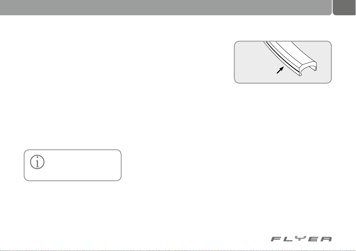
75
• If you do not use your FLYER for a longer
period of time, e.g. in winter, store the pedelec in a dry place with a constant temperature.
• Pump up both tyres with the prescribed tyre
pressure before you store your pedelec.
Further important information on caring for your
pedelec is provided on the website of your respective component manufacturer. A list of links
is printed in chapter 31.
29.2 Parts subject to wear
As a technical product, your FLYER requires
regular checks.
In line with their function and level of use,
many parts on your pedelec are subject to high
levels of wear.
You should have your pedelec
regularly checked by a specialist and have worn parts re-
placed if necessary.
29.3 Tyres
Tyres are subject to wear due to their constant
use. The wear depends on the level of use of
the pedelec and can be influenced by the rider:
• Avoid locking the wheels under braking.
• Regularly check the tyre pressure. Adhere
to the maximum and minimum permitted
air pressure. Both are usually printed on
the side of the tyre.
• If the tyre pressure is too low, pump the
tyres up to the level stated. This helps reduce wear.
• Protect the tyres against damaging influences such as sun rays, petrol, oils etc.
29.4 Rims in connection with rim
brakes
Under braking, both the rim brakes and the
brake pads are in use and are subject to high
levels of wear given their function. Increased
wear can show through fine cracks or deformed rim edges. Clearly visible markings for
wear on the rims make it easier to identify the
level of wear.
Groove as wear marking
• You should check the level of wear of the
rims at regular intervals (see chapter 18.3
“Checking the rims”).
29.5 Brake pads
The brake pads in rim, roller and disc brakes
are subject to wear due to their constant use.
The wear depends on the level of use of the
pedelec. For more demanding usage, i.e. riding in mountainous conditions or sporting use
of the pedelec, it may be necessary to replace
the brake pads relatively frequently. You should
check the wear level of the brake pads at regular intervals and have them replaced by a specialist if required.
Page 80
76
Servicing and caring for your pedelec
29.6 Brake discs
Due to intensive braking and aging, brake discs
are also subject to wear. You can find out the
respective wear levels from your brake manufacturer or your specialist retailer. Have worn
brake discs changed by a specialist.
29.7 Bicycle chain or drive belt
The bicycle chain is also subject to wear due to its
constant use. The wear depends on the care and
maintenance of the bike as well as the level of
use of the pedelec (performance, weather etc.).
• Clean the chain and drive belt at regular
intervals. Oil the chain on a regular basis.
This increases its life span.
• When the chain has reached its wear limit,
have it changed by a specialist (see chapter
22 “Bicycle chain”)
29.8 Chain wheels, sprockets and
jockey wheels
The chain gear system on pedelecs includes
sprockets, chain wheels and jockey wheels,
which are all subject to wear. The wear depends
on the care and maintenance of the bike as well
as the level of use of the pedelec (performance,
weather etc.).
• Clean and oil these parts at regular intervals. This increases their life span.
• When these parts have reached their wear
limit, have them replaced by a specialist.
29.9 Lighting elements in the lighting system
Bulbs and other types of lighting elements are
also subject to wear. It may therefore be necessary to replace them from time to time. In
modern lighting systems, LEDs are sometimes
used as lighting elements. These cannot be individually replaced.
• If a bulb fails, replace it with another new
bulb.
29.10 Handlebar grips
Grips and covers can be worn by normal use.
It may therefore be necessary to replace them
from time to time.
• Check that the grips are secure at regular
intervals.
29.11 Hydraulic oils and lubricants
The effectiveness of hydraulic oils and lubricants reduces with age. If the lubricants are
not replaced, this increases the wear of the affected bearings and parts.
• All affected parts and bearings have to be
cleaned and re-greased at regular intervals.
• You should check the brake fluid for the disc
brakes as well as the Magura model HS11
and HS33 at regular intervals.
29.12 Gear and brake cables
• Check all Bowden cables at regular intervals.
• If your pedelec is often left outside and
subject to the elements, this can cause increased wear, e.g. through UV rays. Parts
damaged by this have to be replaced by a
specialist retailer.
29.13 Paintwork
Clean the paintwork on a regular basis. This
ensures that your pedelec remains in good
condition optically.
• All paintwork has to be regularly checked
for damage. Remedy any damage immediately.
• Allow your FLYER specialist retailer to inform you about taking care of the surfaces.
29.14 Bearings
All bearings on your pedelec, such as the headset, wheel hubs, pedals and bottom bracket
are also subject to wear due to their use. The
wear is dependent on the level and duration of
use and the care.
• Check, clean and oil these parts at regular
intervals with suitable lubricants.
Page 81
30. Regular inspections
77
29.15 Plain bearings and bearings
in full-suspension frames, suspension forks and other suspension
parts
All suspension parts are subject to strong
forces. The same applies for the bearings contained within them. This results in high wear
levels.
Therefore:
• Regularly check that all suspension parts
are working correctly and are secure.
• Carefully read the enclosed instructions
from the manufacturer. Adhere to the care
instructions which the manufacturer provides. You will also find some useful information via the list of links in chapter 31.
• If you have any other questions, your FLYER
retailer will be happy to advise you.
After approximately 200 kilometres ridden or
four to six weeks, have the first inspection of
your pedelec carried out by a specialist. This
is necessary as the spokes bed in during the
first few kilometres, while the brake and gear
cables extend and the bearings wear in. In addition, you honour your warranty agreement by
undergoing an inspection.
• You should clean your pedelec after every
ride and look for any damage.
• An initial inspection has to be carried out by
the specialist retailer.
• Check that all screws, nuts and quick releases are secure. This should then be carried out every 300 - 500 km or every three to
six months.
• Clean your pedelec on a regular basis.
• All moving parts (excluding the brake sur-
faces) have to be greased.
• You should have damage to the paintwork
and any rust patched.
• All bare metal parts (excluding the brake
surfaces) should be treated to combat any
corrosion (rust).
• Defective and damaged parts have to be replaced.
30.1 Inspection plan
30.1.1 Servicing/checks
After riding 200 kilometres after purchase
and then at least once a year, you should have
a specialist retailer carry out a full service
check.
The following parts have to be checked:
• Tyres and wheels.
As well as the torque of the following parts:
• Handlebars,
• Pedals,
• Crankset,
• Seat,
• Seat post and
• Attachment screws.
And the following components should be set up:
• Headset,
• Gear system,
• Brakes,
• Suspension parts.
Page 82
78
Regular inspections
After every ride with your pedelec
Check the following parts:
• Spokes,
• Rims for wear and concentricity,
• Tyres for damage and foreign bodies,
• Quick releases,
• The functionality of the gears and suspension,
• Brakes, hydraulic brakes for any leaks,
• Lighting and
• Bell.
After 300 to 500 kilometres ridden
Have the following parts checked for wear and
replaced by your specialist retailer if required:
• Chain,
• Chain rings,
• Sprockets,
• Rims and
• Brake pads.
• Clean the chain, chain rings and sprockets.
• Oil the chain. Only use lubricant suitable for
this purpose.
• Check that all screwed connections are secure.
After 1,000 kilometres ridden
The brake hubs have to be checked by a specialist retailer and greased or replaced.
After 3,000 kilometres ridden
Have the following parts checked:
• Hubs,
• Headset,
• Pedals,
• Shift cables* and
• Brake cables
by your specialist retailer as well as
• dismantled,
• checked,
• cleaned,
• greased and
• replaced if required.
* Teflon-coated cable housings should not come into contact
with lubricants or oils.
After every rain shower
Clean and grease the following parts:
• Gear system,
• Brakes (excluding the brake surfaces) and
• Chain.
Please note that not all lubricants and care products
are suitable for your pedelec.
Please ask your specialist retailer about
how to correctly apply various products.
By using unsuitable lubricants or care
products, you can damage or impact the
functionality of your pedelec.
Do not allow care products or
oils to taint the brake pads,
brake discs and brake surfaces
on the rims, as this will reduce the performance of the brakes.
Page 83
31. List of links 32. Exchanging components on the “Speed FLYER”
79
The links provided contain important information about your pedelec and the components it
features. The internet pages of the component
manufacturers usually offer the corresponding operating manuals in addition to the most
important information for using and setting up
the components. These are mostly located in
the “Service” or “Download” sections.
www.paul-lange.de/produkte/shimano
www.schwalbe.de/language/index.php5?flash=1
www.magura.com
www.sram.com
www.sram.com/en/srammountain
www.dtswiss.com
www.rohloff.de
www.fallbrooktech.com
www.sram.com/rockshox
www.foxracingshox.com
www.srsuntour-cycling.com
A great deal of basic information about pedelecs, bicycles and their technology is listed
under:
www.smolik-velotech.de,
Although some of it is not completely up to
date, it is very comprehensive.
If you would like to know more about the topic
of pedelecs, you can get more information and
tips on the following internet pages:
www.radfahren.de
www.elektrorad.com
www.pedelecforum.de
In the case of the Speed FLYER, certain parts
have to be used in order to attain the permission to ride.
Specific components are defined in the approvals process which are allowed to be used
on this bicycle.
That means that the Speed FLYER is only
legal if precisely the same parts as the approved bicycle are used.
If parts are subsequently changed or replaced, the same regulations apply as with
other types of vehicles. Only replacement parts
approved for use with your Speed FLYER may
be used. It is possible to acquire individual approval for parts.
In the following list, you can see which parts
of your FLYER may only be replaced with identical original parts.
32.1 Parts which may only be replaced with approved parts
• Frame
• Fork
• Motor unit
• Battery
• Tyres
• Rims
• Brake system
• Front light
• Rear light
• Number plate holder
• Kickstand
• Handlebars
• Stem
32.2 Replacement tyres
If you require, you can select suitable replacement tyres from this list. This list from the
German manufacturer Schwalbe offers a good
overview. You can use the following tyres for
your Speed FLYER:
Page 84
80
Model Line Type Size Max. load*
Marathon Supreme Evolution Falt/ Draht 37-622 110 kg (6 bar)
Marathon Supreme Evolution Falt/ Draht 50-559 140 kg (5 bar)
Marathon Dureme Evolution Falt/ Draht 37-622 110 kg (6 bar)
Marathon Dureme Evolution Falt/ Draht 50-559 140 kg (5 bar)
Marathon Extreme Evolution Falt 37-622 115 kg (6 bar)
Marathon Extreme Evolution Falt 50-559 140 kg (5 bar)
Marathon Plus Performance Draht 37-622 110 kg (6 bar)
Marathon Plus Performance Draht 47-559 125 kg (5 bar)
Marathon Performance Draht 37-622 110 kg (6 bar)
Marathon Performance Draht 50-559 140 kg (5 bar)
Big Apple Performance Falt/Draht 50-622 150 kg (5 bar)
Big Apple Performance Falt/Draht 50-559 125 kg (5 bar)
Big Apple Performance Draht 50-305 70 kg (5 bar)
Big Apple Performance Draht 50-203 70 kg (4 bar)
Kojak Performance Falt/Draht 35-622 110 kg (6,5 bar)
Smart Sam Performance Draht 42-622 120 kg (6 bar)
Smart Sam Performance Draht 54-559 140 kg (4 bar)
Carzy Bob Performance Draht 60-507 130 kg (4,5 bar)
Energizer Active Draht 37-622 85 kg (6 bar)
Energizer Active Draht 40-622 95 kg (6 bar)
Energizer Active Draht 47-559 90 kg (5 bar)
Exchanging components on the “Speed FLYER”
* Max. load with stated tyre pressure
32.3 Components which do not
have to be replaced with approved
replacements
• Crankset
• Pedals: If pedal reflectors are integrated in
the design.
• Mudguard: The front edge of the mudguard
has to be blunt.
• Luggage rack
• Seat / seat post
• Handlebar grips
• Bell: Can be replaced with a bell with equal
quality and audibility.
• Rear-view mirror: Can be replaced by a different type approved rear-view mirror.
• Chain
• Headset
• Inner tube
• Hubs
• Gear components: Only if the largest gear
ratio is not changed.
Page 85
33. Technical information
81
33.1 Permitted overall weight
The permitted overall weight of the pedelec
is made up of the weight of the pedelec, the
weight of the rider and the weight of the luggage transported. The weight of a trailer and
its load are also included in the overall weight.
A trailer load with a maximum weight of 50 kg
(incl. the weight of the trailer itself) should not
be exceeded.
Our bicycles are designed for a maximum
overall weight (rider, luggage and bike) of:
City and hybrid bikes 120 kg
Comfort (1 tube frame) 120 kg
Full suspension bike 120 kg
I:SY 100 kg
Cargo 160 kg
Tandem 210 kg
Folding bike 100 kg
The permissible overall weight of FLYERs with
a carbon frame is the same as those with aluminium frames.
There is a different permissible overall
weight when using lightweight parts, for instance. If this is the case, this is marked on the
pedelec or the respective parts.
33.2 Permitted load of the luggage
rack
Check if the limits for your
luggage rack or bike is different in the information from
the manufacturer.
Maximum load of the front luggage rack on the
FLYER Cargo:
• Rack above the front wheel: 40 kg
• Maximum load of the rear luggage rack: 40 kg
33.3 Torques for screwed connections
A torque wrench has to be used
to tighten screwed connec-
tions. Parts tightened with the
incorrect torque could become loose or
break.
Parts can also be damaged by
incorrectly tightened screws.
You should therefore always adhere to the prescribed torque.
In the case of (hard) aluminium alloys, a screw
has to be inserted to at least x1.4 of the screw
diameter (e.g. nominal diameters of the M5
screw: 5 mm x 1.4 = 7 mm minimum screw-in
depth).
Use a torque spanner to tighten key
screwed connections. The spanner shows the
required torque in Nm (Newton metres).
• You can find the correct torque either on the
part itself or use the amount listed in the
following table.
• If you find a prescribed torque from the
manufacturer of the part, this has priority.
• Special assembly paste has to be used for
fitting carbon parts.
You also have to take other information or markings relating
to the recommended torque
into account.
Page 86
82
Screwed
connection
Thread
Torque
(nm)
Crankset arm,
aluminium
M8x1 30
Pedal 9 / 16“ 30
Front wheel nut allg. 25
Rear wheel nut allg. 30
Stem wedge-shaped
expander nut
M8 23
Stem, Ahead, angle
adjustment
M6 10
Stem, Ahead,
handlebar clamp
M5
M6
M7
5
10
14
Steam, Ahead,
fork shaft
M5
M6
M7
5
10
14
Bar end,
outer clamp
M5
M6
5
10
Seat post,
seat post clamp
M8
M6
20
10
Derailleur clamp M5 5
Brake, pad M6 10
Brake, cable clamp M6 10
Screwed
connection
Thread
Torque
(nm)
Side dynamo,
attachment
M6 10
Derailleur
hanger
M10 x1 16
Inner bearing BSA
According to the
manufacturer’s
instructions
Disc brake caliper, Shimano,
IS and PM
M6 6 to 8
Disc brake caliper, Magura
M6 6
Gear lever
clamp
M5 5
Brake lever
clamp
M5 5
V-brakes, attachment screw
M6 10
Freewheel attachment screw
n. a. 40
Cassette, attachment ring
n. a. 30
Grip, screw-on
M4
M5
3
5
Screwed
connection
Thread
Torque
(nm)
Carbon frame, seat
clamp
M5
M6
5
5
Carbon frame,
bottle holder
M5 5
Carbon frame,
derailleur clamp
M5 4
Technical information
Carbon
33.3.1 General torques for screwed connections
Embossed in the head of the screws you will
find information of the screw quality, e.g. 8.8.
If no other information has been provided
by the manufacturer, the following torques (averages) apply depending on the quality of the
screws:
Page 87
Thread
Size
Quality
V2A /
V4A
8.8 10.9 12.9
M4 3 2,7 3,8 4,6
M5 5 5,5 8 9,5
M6 8 9,5 13 16
M8 20 23 32 39
M10 40 46 64 77
Tyre width
Recommended
tyre pressure
20 mm 9,0 bar 130 psi
23 mm 8,0 bar 115 psi
25 mm 7,0 bar 100 psi
28 mm 6,0 bar 85 psi
30 mm 5,5 bar 80 psi
32 mm 5,0 bar 70 psi
35 mm 4,5 bar 65 psi
37 mm 4,5 bar 65 psi
40 mm 4,0 bar 55 psi
42 mm 4,0 bar 55 psi
44 mm 3,5 bar 50 psi
47 mm 3,5 bar 50 psi
50 mm 3,0 bar 45 psi
54 mm 2,5 bar 35 psi
57 mm 2,2 bar 32 psi
60 mm 2,0 bar 30 psi
83
Please also inform yourself using the information provided by
your tyre manufacturer. This
could possibly be different from the tyre
pressures listed here. Not adhering to
these guidelines can lead to damage to
your tyres and inner tubes.
33.4 Tyres and tyre pressure
The amounts for the recommended tyre pressure can either be named in bar or PSI.
The following table presents the conversions
for the usual pressure levels and shows which
tyre widths these pressures should be applied to.
33.5 Lighting system
The type of replacement light bulbs depend on
the lighting system installed in your pedelec.
The following list provides a guide for finding
the right bulb.
Page 88
84
Lighting used Bulb information
Front light 6 V 2,4 W
Halogen front light 6 V 0,6 W
Rear light 6 V 0,6 W
Rear light with
standlight
6 V 0,6 W
LED lighting
LEDs cannot be
replaced
Dynamo 6 V 3 W
Hub dynamo 6 V 3 W
Technical information
Weight
Tandem weight 35–38 kg
Cargo 32–35 kg
K series 23–25 kg
Folding bike 20–22 kg, R series 20-22 kg
I:sy, S series 22-24 kg
X series 22-25 kg
L series, T series, C series, 25-27 kg
BATTERY capacities:
26V: 8Ah, 10Ah, 12Ah, 15Ah, Ah16
36V: 8Ah, 12Ah, 14Ah
Motors:
26V: 250W,300W, maximum support 1:2,
36V: 250W, maximum support 1:2; 350W, maximum support 1:2.66
Warnings and important information
• Please take note of the following information: The addi-
tional support from the motor
could mean that you travel at a considerably higher speed than you are
used to on your bicycle.
• Please note that the motor of your
FLYER can heat up during long ascents. Do not touch it. You could suffer burns.
• Never attempt to operate your FLYER
with a different battery other than an
original battery. Your specialist retailer can advise you about selecting
the right battery.
• Never remove component covers or
parts. This could expose live parts.
Connecting points could also be live.
Only specialist retailers can repair or
service your bike when it is still live.
• Do not damage or squeeze any cables
when you service, clean or set up
your FLYER.
• If it is no longer possible to use the
bike safely, you may no longer use
your FLYER. This is the case if live
parts or the battery are damaged.
Until it has been checked by a specialist, the FLYER has to be left unused and secured.
• You should be particularly careful if
children have access to the bike. Prevent children from e.g. inserting objects into openings in the bike. They
could suffer a life-threatening electric shock.
• If the FLYER is to be held in an assembly stand, this should only be attached
by the seat post. Carbon or valuable
aluminium frames could be damaged
by the force of the attachment.
Page 89
34. Warranty and guarantee conditions
85
By buying a FLYER electric bike, you are acquiring a high quality, custom-assembled product
made in Switzerland. We therefore offer you
above-average warranty conditions.
34.1 Prerequisites for a warranty or
guarantee claim
BIKETEC AG grants the following guarantee
periods on its electric bikes from the date of
purchase against manufacturing and material
defects:
• Frame: 5 year guarantee against broken
frame
• Other components specific to the FLYER
(motor control unit, Display): 5 years guarantee on material defects
• Motor,
• Controller,
• Control panel/screen
• Battery: 2 years (60% of the nominal capacity)
The legal warranty period of at least 2 years applies for all other parts and equipment components. The wear on parts subject to wear is excluded from warranty and guarantee claims.
During the warranty and guarantee period,
product defects are dealt with by replacing the
parts in question or offering free repair. All
warranty and guarantee services can only be
provided by a certified FLYER specialist retailer
after prior approval by Biketec AG.
The Warranty and guarantee are also
transferrable to subsequent owners. Proof of
purchase (Invoice/dated purchase document
which identifies the bike) is required for this.
The Warranty and guarantee period start
from the date of purchase, or a maximum of 6
months after the bike is shipped from the factory.
The Warraty and guarantee cover complete
bikes which undergo final assembly and tuning
at BIKETEC AG authorised retail outlets.
The guarantee does not cover damage
which is caused through normal usage and
wear (e.g. tyres, inner tubes, chains, brake
pads etc.).
It is the responsibility of the bike owner to
regularly service and care for the bike.
In some EU states, a bike which requires
registration from the category up to 45 km/h is
not permitted to ride with a trailer if a person is
being transported in the trailer. Please inform
yourself about the applicable legal regulations
for you.
34.2 Exclusions from warranty and
guarantee
The warranty and guarantee do not apply for
racing or competitive usage or as part of commercial use.
This guarantee and warranty are nullified if
the FLYER electric bikes are used for anything
apart from there intended use, insufficiently
maintained, incorrectly repaired, rebuilt or
modified, damaged by an accident or by excessive/incorrect use.
Guarantee and/or warranty are only valid
if original components, including those which
have been replaced, are exclusively used.
Parts subject to wear as well as work undertaken by retailers is generally excluded from
guarantee claims.
• Biketec AG reserves the right to deliver or
fit goods of the same functional value when
replacing a FLYER or its components as
part of guarantee or warranty claims.
• Making use of guarantee/warranty services
does not lead to an extension of the original
period of 2 or 5 years.
Adress
Biketec AG
Schwende 1
CH - 4950 Huttwil
Telefon +41 62 959 55 55
Fax +41 62 959 55 66
[email protected]
www.flyer.ch
Page 90
86
Inspections
1st inspection
At the latest after 100 - 300 kilometres or
three months after date of purchase
Order no.: ..........................................................
Date: .................................................................
c All necessary servicing work carried out
(see service and maintenance plan)
Exchanged or repaired parts:
............................................................................
............................................................................
............................................................................
............................................................................
............................................................................
Stamp and signature of the retailer:
2nd inspection
At least after 2,000 kilometres or one year
Order no.: ..........................................................
Date: .................................................................
c All necessary servicing work carried out
(see service and maintenance plan)
Exchanged or repaired parts:
............................................................................
............................................................................
............................................................................
............................................................................
............................................................................
Stamp and signature of the retailer:
3rd inspection
At least after 4,000 kilometres or two
years
Order no.: ..........................................................
Date: .................................................................
c All necessary servicing work carried out
(see service and maintenance plan)
Exchanged or repaired parts:
............................................................................
............................................................................
............................................................................
............................................................................
............................................................................
Stamp and signature of the retailer:
Page 91
87
4th inspection
At least after 6,000 kilometres or three
years
Order no.: ..........................................................
Date: .................................................................
c All necessary servicing work carried out
(see service and maintenance plan)
Exchanged or repaired parts:
............................................................................
............................................................................
............................................................................
............................................................................
............................................................................
Stamp and signature of the retailer:
5th inspection
At least after 8,000 kilometres or four
years
Order no.: ..........................................................
Date: .................................................................
c All necessary servicing work carried out
(see service and maintenance plan)
Exchanged or repaired parts:
............................................................................
............................................................................
............................................................................
............................................................................
............................................................................
Stamp and signature of the retailer:
6th inspection
At least after 10,000 kilometres or five
years
Order no.: ..........................................................
Date: .................................................................
c All necessary servicing work carried out
(see service and maintenance plan)
Exchanged or repaired parts:
............................................................................
............................................................................
............................................................................
............................................................................
............................................................................
Stamp and signature of the retailer:
Page 92
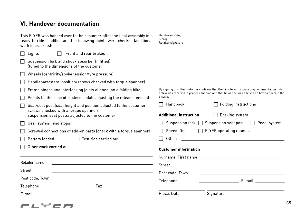
Page 93
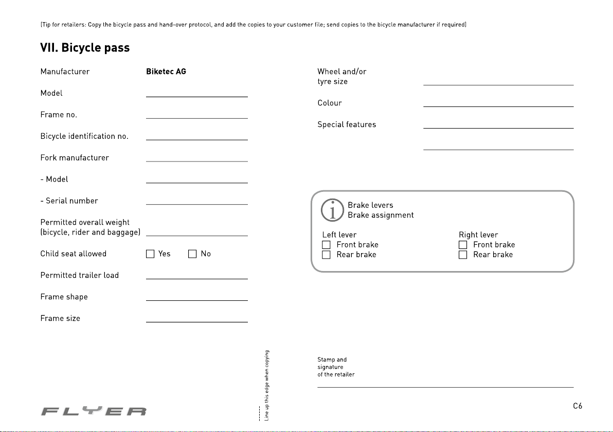
Page 94
Supplied by:
 Loading...