

Page 1
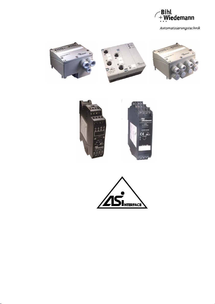
AS-Interface 2.1
AS-Interface Analog Module
User Manual
Page 2
AS-Interface Analog Module Table of Co ntents
Table of Contents
1 The Symbols Used .............................................................................. 6
2 Safety ................................................................................................... 7
2.1 Intended Use ...................................................................................................... 7
2.2 General Safety Information ............................................................................... 7
3 General Information ............................................................................ 8
3.1 Technical Overview of all Modules .................................................................. 9
3.1.1 Analog Modules with 2 Channels in Protection Category IP65 ............................ 9
3.1.2 Analog Modules with 2 Channels in Protection Category IP20 ............................ 9
3.1.3 Analog Modules with 4 Channels in Protection Category IP20 .......................... 10
3.1.4 Analog Modules with 4 Channels, M12 Connection in Protection
3.2 Analog Modules with 2 Channels in Protection Category IP65 ...................11
3.2.1 Analog Modules with 2 Inputs ............................................................................ 11
3.2.2 Analog Modules with 2 Outputs ......................................................................... 11
3.2.3 Analog Module with 4 Pt100 Inputs ................................................................... 12
3.3 Analog Modules with 2 Channels in Protection Category IP20 ...................12
3.3.1 Analog Module with 2 Inputs .............................................................................. 12
3.3.2 Analog Module with 2 Outputs ........................................................................... 12
3.4 Analog Modules with 4 Channels in Protection Category IP20 ...................13
3.4.1 Analog Modules with 4 Inputs ............................................................................ 13
3.4.2 Analog Modules with 4 Outputs ......................................................................... 13
3.4.3 Analog Module with 4 Pt100 Inputs ................................................................... 13
3.5 Analog Modules with 4 Channels, M12 Connection in Protection
3.5.1 Analog Modules with 4 Inputs ............................................................................ 14
3.5.2 Analog Modules with 4 Outputs ......................................................................... 14
3.5.3 Analog Module with 4 Pt100 Inputs ................................................................... 14
3.6 Accessories for Analog Modules in IP65 (optional) ..................................... 14
Category IP65 .................................................................................................... 11
Category IP65 ................................................................................................... 13
4 Connections, Displays and Operating Keys ................................... 15
4.1 Analog Modules in IP65 ................................................................................... 17
4.1.1 Power Supply of Analog Modules in IP65 .......................................................... 17
4.1.1.1 Supplying the Sensors/Actuators by AS-Interface ............................................. 17
4.1.1.2 Supplying the Sensors/Actuators by external Help Voltage 24 V ...................... 17
4.1.1.3 Positioning of Jumpers (Input-/Output Modules) ................................................ 19
4.1.2 Display- and Operating Elements of Analog Modules ....................................... 20
4.1.2.1 Input or Output Modules .................................................................................... 20
4.1.2.2 Pt100 Module .................................................................................................... 20
4.1.2.3 LEDs of Input-/Output Modules .......................................................................... 21
4.1.2.4 LEDs of Pt100 Module ....................................................................................... 21
4.2 Analog Modules in IP20 with 2 Channels ...................................................... 22
4.2.1 Supplying the Sensors/Actuators ....................................................................... 22
4.2.2 Display- and Operating Elements ...................................................................... 23
Subject to reaso nable modifications due to technical advances. Copyright Bihl+ Wiedemann, Printed in Germa ny
2
Bihl+Wiedemann GmbH · D-68199 Mannheim · Tel. +49-621-339960 · Fax +49-621-3392239 · Internet http://www.bihl-wiedemann.de
issue date 20.1.20 04
Page 3
AS-Interface Analog Module Table of Contents
4.2.3 LEDs of Input-/Output Modules ......................................................................... 25
4.3 Analog Modules in IP20 with 4 Channels ...................................................... 26
4.3.1 Power supply of Analog Modules ...................................................................... 26
4.3.2 Display and Operating Elements ....................................................................... 26
4.3.2.1 Input Modules .................................................................................................... 27
4.3.2.2 Output Modules ................................................................................................. 27
4.3.2.3 Pt100 Module .................................................................................................... 27
4.3.3 LEDs of Input-/Output Modules ......................................................................... 28
4.3.4 LEDs of Pt100 Module ....................................................................................... 29
4.4 Analog Modules with 4 Channels and M12 Connection in Protection
Category IP65 ................................................................................................... 30
4.4.1 Power supply of Analog Modules ...................................................................... 30
4.4.2 Display and Operating Elements ....................................................................... 30
4.4.2.1 In-/Output Modules ............................................................................................ 30
4.4.2.2 Input Modules .................................................................................................... 31
4.4.2.3 Output Modules ................................................................................................. 31
4.4.2.4 Pt100 Module .................................................................................................... 31
4.4.3 LEDs of Input-/Output Modules ......................................................................... 32
4.4.4 LEDs of Pt100 Module ....................................................................................... 33
4.5 Pin Configuration ............................................................................................ 34
4.5.1 Analog Modules in IP65 with 2 Channels .......................................................... 34
4.5.1.1 Pin Configuration of Analog Input Modules in IP65 with 2 Channels ................ 34
4.5.1.2 Pin Configuration of the Analog Output Module (0 … 20 mA) in IP65 with
2 Channels ........................................................................................................ 36
4.5.1.3 Pin Configuration of the Analog Output Module (0 … 10 V) in IP65 with
2 Channels ........................................................................................................ 38
4.5.1.4 Pin Configuration of the AS-Interface Pt100 Module in IP65 with 4 Channels .. 39
4.5.2 Analog Modules in IP20 with 2 Channels .......................................................... 40
4.5.2.1 Pin Configuration of Analog Input Modules in IP20 with 2 Channels ................ 40
4.5.2.2 Pin Configuration of the Analog Output Module (0 … 20 mA) in IP20 with
2 Channels ........................................................................................................ 42
4.5.2.3 Pin Configuration of the Analog Output Module (0 … 10 V) in IP20 with
2 Channels ........................................................................................................ 44
4.5.3 Analog Modules in IP20 with 4 Channels .......................................................... 45
4.5.3.1 Pin Configuration of the Analog Input Modules in IP20 with 4 Channels .......... 45
4.5.3.2 Pin Configuration of the Analog Output Module (0 … 20 mA) in IP20 with
4 Channels ........................................................................................................ 48
4.5.3.3 Pin Configuration of the Analog Output Module (0 … 10 V) in IP20 with
4 Channels ........................................................................................................ 50
4.5.3.4 Pin Configuration of the AS-Interface Pt100 Module in IP20 with 4 Channels .. 51
4.5.4 Analog Modules with M12 Connection in IP65 with 4 Channels ...................... 52
4.5.4.1 Pin Configuration of the Analog Input Modules in IP65 with 4 Channels .......... 52
4.5.4.2 Pin Configuration of the Analog Output Module (0 … 20 mA) in IP65 with
4 Channels ........................................................................................................ 54
4.5.4.3 Pin Configuration of the Analog Output Module (0 … 10 V) in IP65 with
4 Channels ........................................................................................................ 55
4.5.4.4 Pin Configuration of the AS-Interface Pt100 Module in IP65 with 4 Channels .. 56
issue date 20.1.20 04
Subject to reas onable modifications due to technical advances. Copyright Bihl+ Wiedemann, Printed in Germa ny
Bihl+Wiedemann GmbH · D-68199 Mannheim · Tel. +49-621-339960 · Fax +49-621-3392239 · Internet http://www.bihl-wiedemann.de
3
Page 4
AS-Interface Analog Module Table of Co ntents
5 Operating the Modules ..................................................................... 57
5.1 Addressing the Modules ................................................................................. 57
5.2 Operation of Analog Input Modules in IP20 and IP65 ................................... 57
5.2.1 Slave Profile in IP20 und IP65 ........................................................................... 57
5.2.2 Parameterization of the Analog Input Modules in IP20 and IP65 ...................... 57
5.2.2.1 Analog Module in IP20, 2 Channels and in IP65 ............................................... 58
5.2.2.2 Analog Modules in IP20 and IP65 with M12 Connection, 4 Channels ............... 59
5.2.3 Measuring Range of Analog Input Modules ....................................................... 60
5.2.4 Transmission Time of Analog Parameters ......................................................... 61
5.2.4.1 Transmission Time of Analog Parameters for 2 Channels ................................ 61
5.2.4.2 Transmission Time of Analog Parameters for 3 Channels ................................ 62
5.2.4.3 Transmission Time of Analog Parameters for 4 Channels ................................ 62
5.3 Operation of AS-Interface Analog Output Modules in IP20 and IP65 ......... 63
5.3.1 Slave Profile ....................................................................................................... 63
5.3.2 Parameterization of Analog Output Modules in IP20 and IP65 .......................... 63
5.3.2.1 Analog Output Module in IP65 ........................................................................... 63
5.3.2.2 Analog Output Modules in IP20, 2 Channels ..................................................... 64
5.3.2.3 Analog Output Modules in IP20 and IP65 with M12 Connection, 4 Channelsl ..64
5.3.3 Measuring Range of Analog Output Modules .................................................... 65
5.3.4 Transmission Time of Analog Parameters ......................................................... 66
5.3.4.1 Transmission Time of Analog Parameters for 2 Channels ................................ 66
5.3.4.2 Transmission Time of Analog Parameters for 4 Channels ................................ 66
5.4 Operation of the Pt100 Modules in IP20 and IP65 ......................................... 67
5.4.1 Slave Profile ....................................................................................................... 67
5.4.2 Parameterization of the AS-Interface Pt100 Modules ........................................ 67
5.4.3 Measuring range of the AS-Interface Pt100 Module ..........................................68
5.4.4 Transmission Time of Analog Parameters of the AS-Interface Pt100 Module ... 68
6 We Are Interested in Your Opinion! ................................................. 69
Subject to reaso nable modifications due to technical advances. Copyright Bihl+ Wiedemann, Printed in Germa ny
4
Bihl+Wiedemann GmbH · D-68199 Mannheim · Tel. +49-621-339960 · Fax +49-621-3392239 · Internet http://www.bihl-wiedemann.de
issue date 20.1.20 04
Page 5
AS-Interface Analog Module
Declaration of Conformity
according to 89/336/EEC and 73/23/EEC
Bihl+Wiedemann GmbH, Mannheim, hereby declares under its sole responsibility
that the products mentioned below are according to the listed harmonized standards
or normative documents and (where neccessary) a component body has been released.
Specification: AS-Interface Analog Module
Article-no.: 1232, 1233, 1234, 1235, 1254, 1345, 1364, 1365, 1366, 1367,
1368, 1412
Applied harmonized Standards:
EN 50081-2
EN 61000-6-2
Applied national standards or normative documents:
AS-Interface Complete Specification (EN50295)
Prüfungsordnung für AS-Interface Slaves
Manufacturer: Bihl+Wiedemann GmbH
Date: 01.03.01 Bernhard Wiedemann
issue date 20.1.20 04
Subject to reas onable modifications due to technical advances Copyright Bihl+ Wiedemann, Printed in Germa ny
Bihl+W iedemann GmbH · D -68199 Mannh eim · Phone +49-62 1-339960 · Fax +49 -621-3392239 · I nternet http://w ww.bihl-wiedeman n.de
5
Page 6
AS-Interface Analog Module The Symbols Used
1 The Symbols Used
This symbol warns the user of possible danger. Not following this
warning can lead to personal injury or death and/or destruction of
the equipment.
This symbol warns the user of a possible failure. Not following this
warning can lead to total failure of the device or any other connected
equipment.
This symbol draws the user's attention to important information.
Subject to reasonable modifications due to technical advances Copyright Bihl+Wiedemann, Printed in Germany
6
Bihl+W iedemann GmbH · D -68199 Mannh eim · Phone +49-62 1-339960 · Fax +49 -621-3392239 · I nternet http://w ww.bihl-wiedemann .de
issue date 20.1.20 04
Page 7
AS-Interface Analog Module Safety
2 Safety
2.1 Intended Use
The protection of operating personnel and the system against possible danger is not guaranteed if the control interface unit is not operated in accordance with its intended use.
The device may only be operated by appropriately qualified personnel in accordance with this operating manual.
2.2 General Safety Information
Safety and correct functioning of the device cannot be guaranteed if
any operation other than that described in this operation manual is
performed.
The connecting of the equipment and any maintenance work to be
carried out with voltage applied to the equipment must exclusively
be performed by appropriately qualified electrotechnical personnel.
In case a failure cannot be repaired, the device must be taken out of
operation and kept from inadvertently being put back into operation.
Repair work is to be carried out by the manufacturer only. Additions
or modifications to the equipment are not allowed and will void the
warranty.
The operator is responsible for the observance of local safety standards.
issue date 20.1.20 04
Subject to reas onable modifications due to technical advances Copyright Bihl+ Wiedemann, Printed in Germa ny
Bihl+W iedemann GmbH · D -68199 Mannh eim · Phone +49-62 1-339960 · Fax +49 -621-3392239 · I nternet http://w ww.bihl-wiedeman n.de
7
Page 8
AS-Interface Analog Module General Information
3 General Information
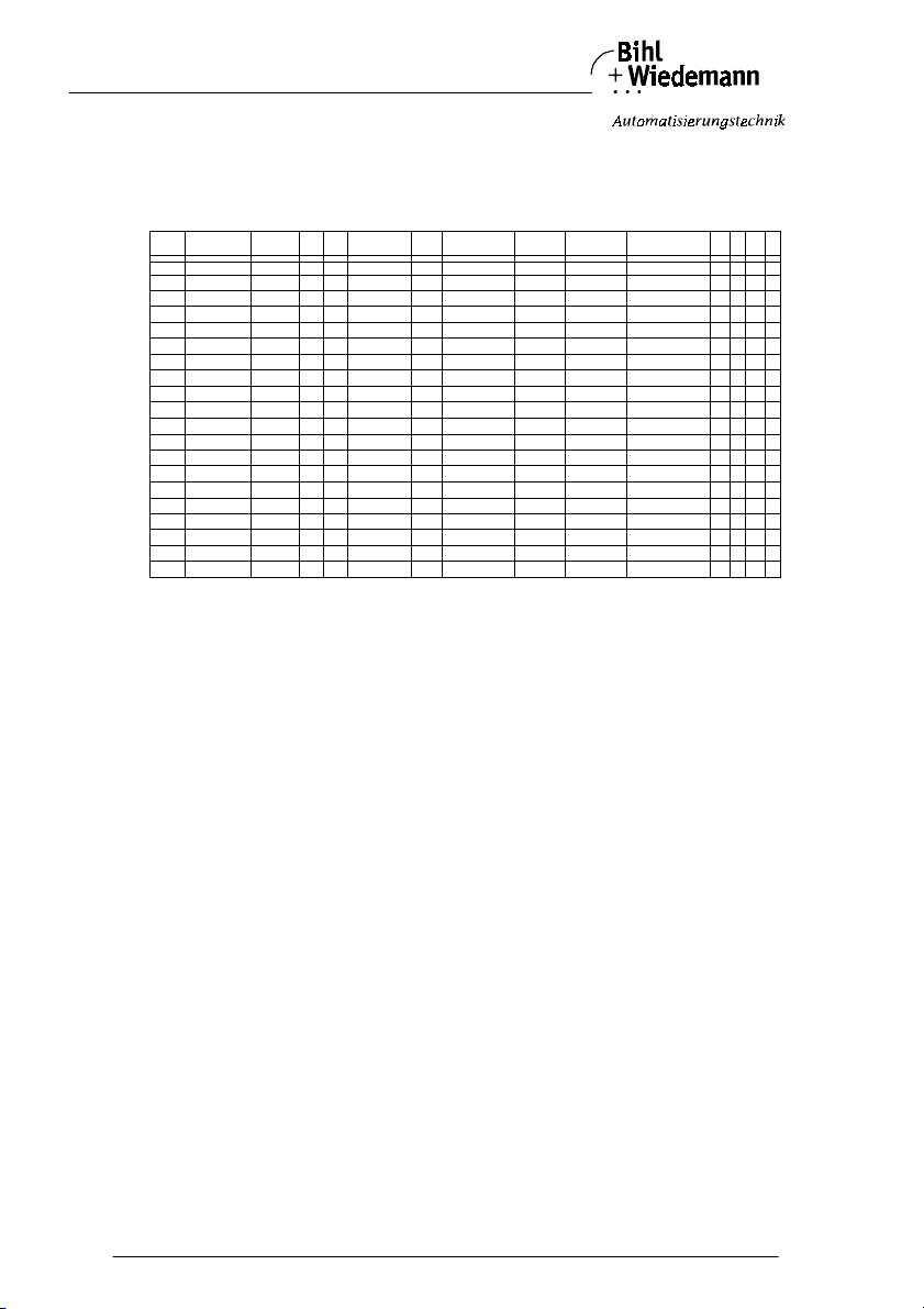
This operating instruction holds for the following devices of the Bihl+Wiedemann
GmbH:
In-
Out-
AS-Interface
Article Type Channels
1364 4 - 20 mA 4 4 "7.3" X 105 * 22.5 * 114 IP20 Combicon Combicon F 3 E 7
1365 0 - 10 V 4 4 "7.3" X 105 * 22.5 * 114 IP20 Combicon Combicon F 3 E 7
1366 0 - 20 mA 4 4 "7.3" X 105 * 22.5 * 114 IP20 Combicon Combicon F 3 6 7
1367 0 - 10 V 4 4 "7.3" X 105 * 22.5 * 114 IP20 Combicon Combicon F 3 6 7
1368 PT100 4 4 "7.3" X 105 * 22.5 * 114 IP20 Combicon Combicon F 3 E 7
1232 4 - 20 mA 2 2 "7.3" 90 * 80 * 70 IP65 Piercing con. PG + Cage clamps F 3 D 7
1233 0 - 10 V 2 2 "7.3" 90 * 80 * 70 IP65 Piercing con. PG + Cage clamps F 3 D 7
1234 0 - 20 mA 2 2 "7.3" 90 * 80 * 70 IP65 Piercing con. PG + Cage clamps F 3 5 7
1235 0 - 10 V 2 2 "7.3" 90 * 80 * 70 IP65 Piercing con. PG + Cage clamps F 3 5 7
1254 PT100 4 4 "7.3" 90 * 80 * 70 IP65 Piercing con. PG + Cage clamps F 3 E 7
1345 4-20mA/0-10V 2 2 "7.3" 99 * 22.5 * 92 IP20 Combicon Combicon F 3 D 7
1412 0-20mA/0-10V 2 2 "7.3" 99 * 22.5 * 92 IP20 Combicon Combicon F 3 5 7
1359 4 - 20 mA 4 4 "7.3" X 90 * 80 * 46,9 IP65 Piercing con. M12 F 3 E 7
1360 0 - 10 V 4 4 "7.3" X 90 * 80 * 46,9 IP65 Piercing con. M12 F 3 E 7
1361 0 - 20 mA 4 4 "7.3" X 90 * 80 * 46,9 IP65 Piercing con. M12 F 3 6 7
1362 0 - 10 V 4 4 "7.3" X 90 * 80 * 46,9 IP65 Piercing con. M12 F 3 6 7
1363 PT100 4 4 "7.3" X 90 * 80 * 46,9 IP65 Piercing con. M12 F 3 E 7
puts
puts
With the new AS-Interface specification it is possible to transmit analog values via
AS-Interface as simple as binary signals. For these reasons the new AS-Interface
slave profiles 7.3 and 7.4 for the transmission of analog values have been defined.
According to the profil 7.3 the AS-Interface master puts the analog slaves into operation in the same way as the digital slaves and startes the data exchange automatically. The host system (PC, PLC, Fieldbus) can read the 16 bit value directly
out of the AS-Interface master. The analog value transmission between AS-Interface master and AS-Inter face slave is done invisibely for the user.
The user's advantages are obvious. He does not have to pay attention to the handling of the data transmission. This means in the majority of applications that the
transmission time of analog values via AS-Interface will be reduced because the
transmission time depends on the AS-Interface cycle time and not as it was before
on the cycle time of the PLC program.
Bihl+Wiedemann has developed AS-Interface analog modules for safe and direct
connection of sensors and actuators according to the new standardized Profile
7.3.
Analog data such as pressure and room temperature is transmitted by the module
in interference-free digital signal form. In factory applications the module is installed as with isolation amplifier or real power transformer. They are simply clambed
onto the AS-Interface cable and directly supported by the AS-Interface master:
Simply Plug and Play! There is no need to program a function block to transmit the
AS-Interface analog value via AS-Interface.
Profile
Galv.
sep.
Housing
L * W * H [mm]
Protection
class
Contakt
AS-Inteface
Contact-
Analog side
ID1 ID ID2 IO
Subject to reasonable modifications due to technical advances Copyright Bihl+Wiedemann, Printed in Germany
8
Bihl+W iedemann GmbH · D -68199 Mannh eim · Phone +49-62 1-339960 · Fax +49 -621-3392239 · I nternet http://w ww.bihl-wiedemann .de
issue date 20.1.20 04
Page 9
AS-Interface Analog Module General Information
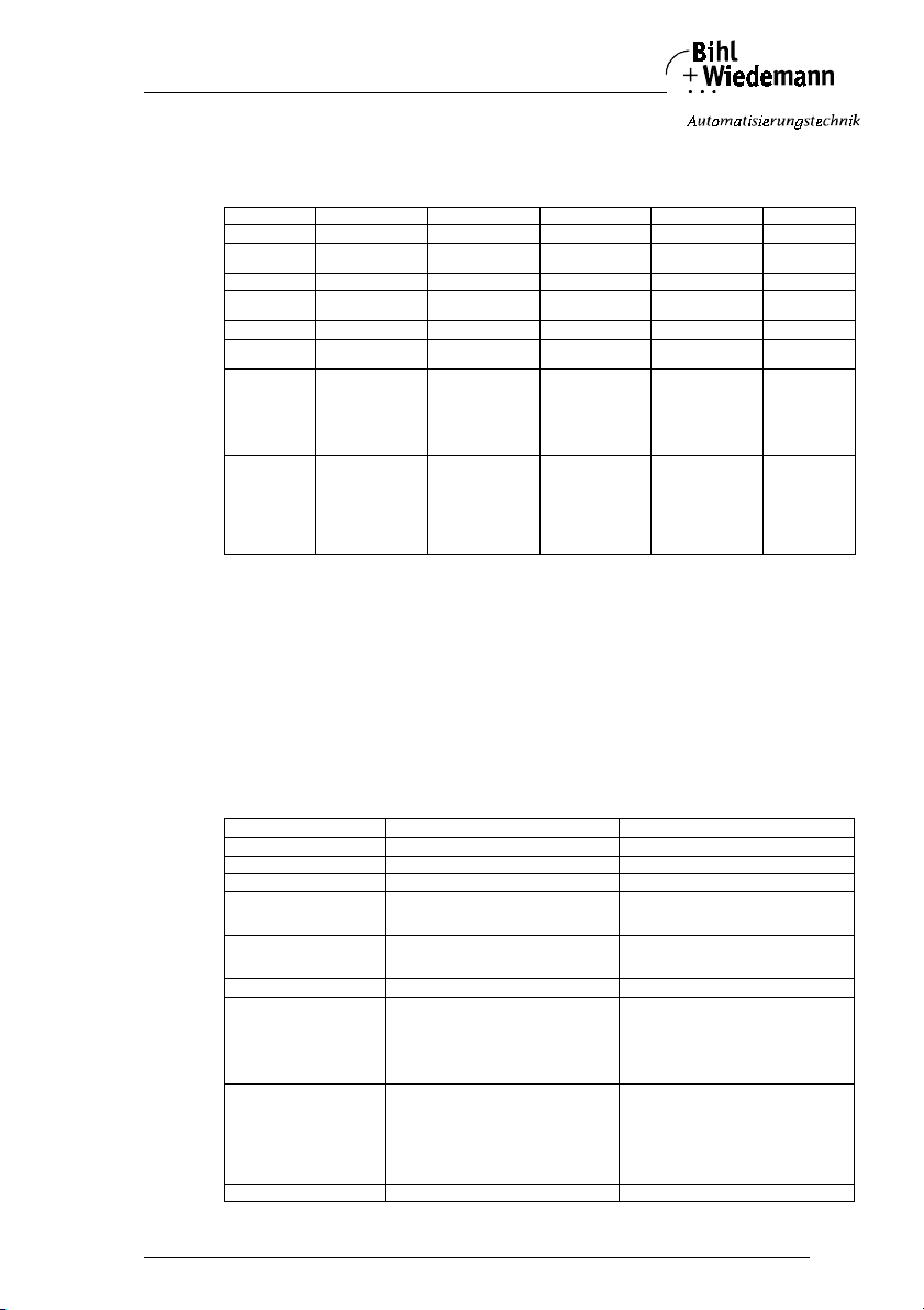
3.1 Technical Overview of all Modules
3.1.1 Analog Modules with 2 Channels in Protection Category IP65
Features Current input Voltage input Current output Voltage output Pt100
Number of inputs 22 4
Number of outputs
Resolution 16 Bit 16 Bit 16 Bit 16 Bit 16 Bit
Kind of measuring
Kind of output current voltage
Display of channel states
Potential relationship between
sensors/aktuators/Pt100 and
AS-Interface
AS-Interface
parameters
curren voltage temperature
yes yes yes yes yes
• +24 V out of AS-Interface:
potential connected to
AS-Interface
• +24 V out of external
help voltage:
galv. sepera tion
P0: 1 50 Hz filter
0: 60 Hz filter
P1: 1: channel 2 on
0: channel 2 off
P2: 1: P -error allowed
0: not allowed
P3: not used
• +24 V out of AS-Interface:
potential connected to
AS-Interface
• +24 V out of external
help voltage:
galv. sepera tion
P0: 1 50 Hz filter
0: 60 Hz filter
P1: 1: channel 2 on
0: channel 2 off
P2: 1: P -error allowed
0: not allowed
P3: not used
22
• +24 V out of AS-Interface:
potential connected to
AS-Interface
• +24 V out of external
help voltage:
galv. sepera tion
P0, P1, P3:
not used
P2: 1: P-error allowed
0: not used
• +24 V out of AS-Interface:
potential connected to
AS-Interface
• +24 V out of external
help voltage:
galv. seperation
P0, P1, P3:
not used
P2: 1: P-error allowed
0: not used
potential connected to AS-Interface
P0: 1: 50 Hz filt er
P1, P2 :
P3: senso r
LED displays:
LED (green) Analog 1: State of channel 1
LED (green) Analog 2: State of channel 2
LED (green) Analog 3: State of channel 3 (only for Pt100 module)
LED (green) Analog 4: State of channel 4 (only for Pt100 module)
LED (green) power: Voltage supply +24 V out of AS-Interface for analog
part OK (not for Pt100-Module)
LED (green) AS-i: Voltage on AS-Interface terminals OK
LED (red) FAULT: AS-Interface communication fault, peripheral fault
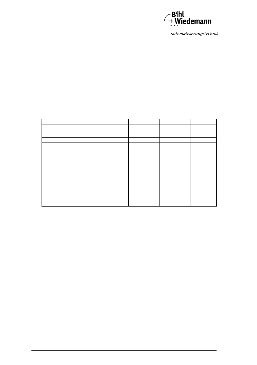
3.1.2 Analog Modules with 2 Channels in Protection Category IP20
Features Input Output
Number of inputs 22
Number of outputs
Resolution 16 Bit A/D 16 Bit
Kind of measuring channelwise
Kind of output channelwise
Display of channel states yes yes
Potential relationship between
analog part and AS-Interface
AS-Interface parameters P0: 1 50 Hz filter
issue date 20.1.20 04
Subject to reas onable modifications due to technical advances Copyright Bihl+ Wiedemann, Printed in Germa ny
Feature Cannel 2 can be switched off with switch S2
Bihl+W iedemann GmbH · D -68199 Mannh eim · Phone +49-62 1-339960 · Fax +49 -621-3392239 · I nternet http://w ww.bihl-wiedeman n.de
• voltage
• current
power supply of the sensors can be made of either
out of AS-Interface or out of external help voltage by
slide switch S1:
• +24 V out of AS-Interface:
potential connected to AS-Interface
• +24 V out of external help voltage:
galv. speration
0: 60 Hz filter
P1: 1: channel 2 on
0: channel 2 off
P2: 1: P -error allowed
0: not allowed
P3: not used
• voltage
• current
power supply of the sensors can be made of either
out of AS-Interface or out of external help voltage by
slide switch S1:
• +24 V out of AS-Interface:
potential connected to AS-Interface
• +24 V out of external help voltage:
galv. sperationnnung:
P0: 1 automatic recognition
0: mode changeable through P1, P3
P1: 1: channel 1 current
0: channel 1 voltage
P2: 1: P-error allowed
0: not allowed
P3: 1: channel 2 current
0: channel 2 voltage
0: 60 Hz filter
P-error release
of cannel
1: 2-wire
0: 3-wire
9
Page 10
AS-Interface Analog Module General Information
LED displays:
LED (green) Input 1/Output 1: State of channel1
LED (green) Input 2/Output 2: State of channel 2
LED (green) Input 1/Output 1: Voltage/current channel 1
LED (green) Input 2/Output 2: Voltage/current channel 2
LED (green) PWR: Voltage on AS-Interface terminals OK
LED (red) FAULT: AS-Interface communication fault, peripheral
fault
LED (green) AUX: External help voltage 24 V OK
LED (green) INT: Voltage supply out of AS-Interface for analog
part OK
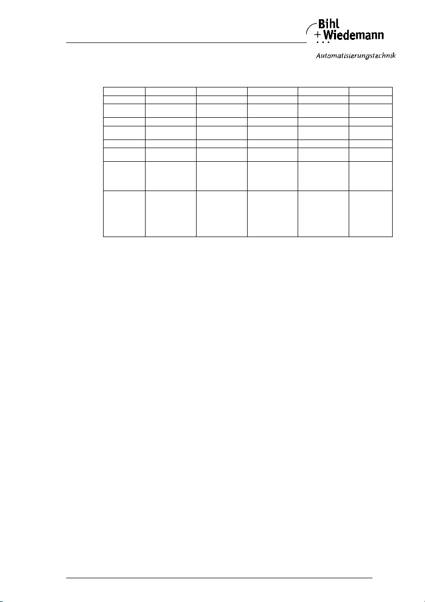
3.1.3 Analog Modules with 4 Channels in Protection Category IP20
Features Current intput Voltage input Current output Voltage output Pt100
Number of inputs 44 4
Number of outputs
Resolution 16 B it 16 B it 16 Bit 16 Bit 16 Bit
Kind of measuring
Kind of output current voltage
Display of channel states
Potential relationship between
analog part and
AS-Interface
AS-Interface
parameters
current voltage temperature
yes yes yes yes yes
galvanical speration galvanical speration galvanical speration galvanical speration galv. speration
P0: 1 50 Hz filter
0: 60 Hz filter
P1, P2:channal on/off
P3: 1: P-error allowed
0: not allowed
P0: 1 50 Hz filter
0: 60 Hz filter
P1, P2:channal on/off
P3: 1: P-error allowed
0: not allowed
44
P0: 1 Profile 7.3 is
monitored
0: Profile 7.3 is not
monitored
P1: not used
P2: 1: P-error allowed
0: not allowed
P3: not used
P0: 1 Profile 7.3 is
monitored
0: Profile 7.3 is not
monitored
P1: not used
P2: 1: P-error allowed
0: not allowed
P3: not used
LED-Anzeigen:
LED (yellow) I1/O1: State of channel 1
LED (yellow) I2/O2: State of channel 2
LED (yellow) I3/O3: State of channel 3
LED (yellow) I4/O4: State of channel 4
LED (green) DIAG: Diagnosis
LED (green) AUX: External help voltage 24 V OK (not for Pt100 module)
LED (green) PWR: Voltage on AS-Interface terminals OK
LED (red) FAULT: AS-Interface communication fault, peripheral fault
P0:1 : 50 H z filter
0: 60 Hz filter
P1, P2:
P-error release
of cannel
P3: sensor
1: 2-wire
0: 4-wire
Subject to reasonable modifications due to technical advances Copyright Bihl+Wiedemann, Printed in Germany
10
Bihl+W iedemann GmbH · D -68199 Mannh eim · Phone +49-62 1-339960 · Fax +49 -621-3392239 · I nternet http://w ww.bihl-wiedemann .de
issue date 20.1.20 04
Page 11
AS-Interface Analog Module General Information
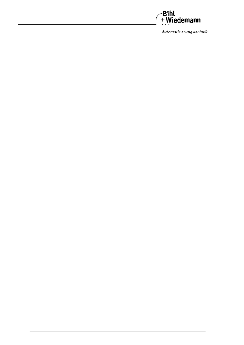
3.1.4 Analog Modules with 4 Channels, M12 Connection in Protection Category IP65
Features Current intput Voltage input Current output Voltage output Pt100
Number of inputs 44 4
Number of outputs
Resolution 16 Bit 16 Bit 16 Bit 16 Bit 16 Bit
Kind of measuring
Kind of output current voltage
Display of channel states
Potential relationship between
sensors/aktuators/Pt100 and
AS-Interface
AS-Interface
parameters
current voltage temperature
yes yes yes yesja yes
galvanical speration galvanical speration galvanical speration galvanical speration galv. speration
P0: 1 bridge active
0: bridge not active
P1, P2:channel on/off
P3: 1: P -error allowed
0: not allowed
P0: not used
P1, P2: channel on/off
P3: 1: P-error allowed
0: not allowed
44
P0: 1 Profile 7.3 is
monitored
0: P rofile 7.3 is not
monitored
P1: not used
P2: 1: P-error allowed
0: not allowed
P3: not used
P0: 1 Profile 7.3 is
monitored
0: Profile 7.3 is not
monitored
P1: not used
P2: 1: P-error allowed
0: not allowed
P3: not used
LED displays:
LED (yellow) In 1/Out 1: State of channel 1
LED (yellow) In 2/Out 2: State of channel 2
LED (yellow) In 3/Out 3: State of channel 3
LED (yellow) In 4/Out 4: State of channel 4
LED (green) AUX: External help voltage 24 V OK (not for Pt100 module)
LED (green) PWR: V oltage on AS-Interface terminals OK
LED (red) FAULT: AS-Interface communication fault, peripheral fault
P0: 1: 50 Hz filter
0: 60 Hz filter
P1, P2:
P-error release
of cannel
P3: sensor
1: 2-wi re
0: 4-wi re
3.2 Analog Modules with 2 Channels in Protection Category IP65
The range consists of 5 AS-Interface analog modules:
2 analog inputs 0 - 10 V, 2 analog inputs 4 - 20 mA, 4 analog inputs Pt100, 2 analog outputs 0 - 10 V, 2 analog outputs 0 - 20 mA.
3.2.1 Analog Modules with 2 Inputs
The analog modules have 2 analog inputs. The conversion of the measured value
and the data transmission via AS-Interface occurs asynchronically according to
AS-Interface Profile 7.3. 2 analog sensors can be connected via cage clamp terminals. The sensors can be supplied by AS-Interface or external help voltage (according to PELV) via the black ribbon cable. The resolution of the analog data is
16 Bit. The analog modules contain 50 Hz and 60 Hz filters. These filters can be
optionally switched with the help of the AS-Interface parameters.
The measuring range of voltage input modules amounts to 0 - 10 V and of current
input modules 4 - 20 mA.
3.2.2 Analog Modules with 2 Outputs
The analog modules have 2 analog outputs. The digital-analog conversion and the
data transmission via AS-Interface occurs asynchronically according to AS-Interface Pr ofile 7.3. 2 analog actuators can be connected via cage clamp terminals.
issue date 20.1.20 04
Subject to reas onable modifications due to technical advances Copyright Bihl+ Wiedemann, Printed in Germa ny
Bihl+W iedemann GmbH · D -68199 Mannh eim · Phone +49-62 1-339960 · Fax +49 -621-3392239 · I nternet http://w ww.bihl-wiedeman n.de
11
Page 12
AS-Interface Analog Module General Information
The actuators can be supplied by AS-Interface or external help voltage (according
to PELV) via the black ribbon cable. The resolution of the analog data is 16 bit.
The measuring range of voltage output modules amounts to 0 - 10 V and of current output modules 0 - 20 mA.
3.2.3 Analog Module with 4 Pt100 Inputs
The analog module has got 4 Pt100 inputs. The commission of the measured value and the data transmission via AS-Interface occurs asynchronically according
to AS-Interface Profile 7.3. 4 analog sensors can be connected via cage clamp terminals. The sensors are supplied by AS-Interface.
The resolution of the analog data is 16 Bit/0,1°C. The Pt100 module contains
50 Hz and 60 Hz filters. These filters can be optionally switched with the help of
the AS-Interface parameters.
3.3 Analog Modules with 2 Channels in Protection Category IP20
The range of these analog modules consits of 2 modules: A module with 2 analog
inputs 0 - 10 V/4 - 20 mA and a mdoule with 2 analog outputs 0 - 10 V/0 - 20 mA.
3.3.1 Analog Module with 2 Inputs
The analog module has 2 analog inputs.
The connection of sensors is made by Combicon clamps. Current or voltage signals can be attached over different clamps.
This module even can detect automatically, if there is a current or a voltage signal
at the module´s input. A channel input can only detect either a voltage or a current
signal each.
The current supply of the sensors can take place depending upon position of a
slide switch from AS-Interface or from external help voltage (after PELV). With the
help of a 2. slide switch the 2. channel in favor of faster data communication can
be switched off. The position of the slide switches is indicated over LEDs.
The conversion of the measured value and the data transmission via AS-Interface
occurs asynchronically according to AS-Interface Profile 7.3. The resolution of the
analog data is 16 Bit. The analog modules contains 50 Hz and 60 Hz filters. These
filters can be optionally switched with the help of the AS-Interface parameters.
3.3.2 Analog Module with 2 Outputs
The analog module has 2 analog outputs.
The connection of actuators is made by Combicon clamps. Current or voltage signals can be delivered over different clamps.
This module even can detect automatically, if there is a current or a voltage processing actuator at the module´s output. At a channel output can only be detected
either a voltage or a current processing device each.
The current supply of the actuators can take place depending upon position of a
slide switch from AS-Interface or from external help voltage (after PELV). The position of the slide switch is indicated over LEDs. The conversion of the measured
value and the data transmission via AS-Interface occurs asynchronically according to AS-Interface Profile 7.3. The resolution of the analog data is 16 Bit.
Subject to reasonable modifications due to technical advances Copyright Bihl+Wiedemann, Printed in Germany
12
Bihl+W iedemann GmbH · D -68199 Mannh eim · Phone +49-62 1-339960 · Fax +49 -621-3392239 · I nternet http://w ww.bihl-wiedemann .de
issue date 20.1.20 04
Page 13

AS-Interface Analog Module General Information
3.4 Analog Modules with 4 Channels in Protection Category IP20
The range consists of 5 AS-Interface analog modules: 2 modules with 4 analog inputs 0 - 10 V or 4 - 20 mA respectively, 2 modules wit h 4 analog outputs 0 - 10 V
or 0 - 20 mA respectively and a module 4 Pt100 inputs.
3.4.1 Analog Modules with 4 Inputs
The analog module has 4 analog inputs.
The connection of sensors is made by Combicon clamps. The sensors can be supplied by AS-Interface or external help voltage (according to PELV). The current
supply switches automatically to external help voltage, as soon as this is set up.
The sensors and AS-Interface are galvanical seperated.
The conversion of the measured value and the data transmission via AS-Interface
occurs asynchronically according to AS-Interface Profile 7.3.
The resolution of the analog data is 16 Bit. The analog modules contains 50 Hz
and 60 Hz filters. These filters can be optionally switched with the help of the
AS-Interface parameters.
3.4.2 Analog Modules with 4 Outputs
The analog module has 4 analog outputs.
The connection of actutators is made by Combicon clamps. The actutators can be
supplied by AS-Interface or external help voltage (according to PELV). The current
supply switches automatically to external help voltage, as soon as this is set up.
The actutators and AS-Interface are galvanical seperated.
The conversion of the measured value and the data transmission via AS-Interface
occurs asynchronically according to AS-Interface Profile 7.3. The resolution of the
analog data is 16 Bit.
3.4.3 Analog Module with 4 Pt100 Inputs
The analog module has got 4 Pt100 inputs.
The connection of actutators is made by Combicon clamps. The sensors and
AS-Interface are galvanical seperated. The commission of the measured value
and the data transmission via AS-Interface occurs asynchronically according to
AS-Interface Profile 7.3.
The resolution of the analog data is 16 Bit. The analog modules contains 50 Hz
and 60 Hz filters. These filters can be optionally activated with the help of the
AS-Interface parameters.
3.5 Analog Modules with 4 Channels, M12 Connection in Protection Category IP65
The range consists of 5 AS-Interface analog modules: 2 modules with 4 analog inputs 0 - 10 V or 4 - 20 mA respectively, 2 modules wit h 4 analog outputs 0 - 10 V
or 0 - 20 mA respectively and a module 4 Pt100 inputs.
issue date 20.1.20 04
Subject to reas onable modifications due to technical advances Copyright Bihl+ Wiedemann, Printed in Germa ny
Bihl+W iedemann GmbH · D -68199 Mannh eim · Phone +49-62 1-339960 · Fax +49 -621-3392239 · I nternet http://w ww.bihl-wiedeman n.de
13
Page 14
AS-Interface Analog Module General Information
3.5.1 Analog Modules with 4 Inputs
The analog module has 4 analog inputs.
The connection of sensors is made by M12 connection. The sensors can be supplied by AS-Interface or external help voltage (according to PELV). The current
supply switches automatically to external help voltage, as soon as this is set up.
The sensors and AS-Interface are galvanical seperated.
The conversion of the measured value and the data transmission via AS-Interface
occurs asynchronically according to AS-Interface Profile 7.3. The resolution of the
analog data is 16 Bit.
3.5.2 Analog Modules with 4 Outputs
The analog module has 4 analog outputs.
The connection of actutators is made by M12 connection. The analog part can be
supplied by AS-Interface or external help voltage (according to PELV). The current
supply switches automatically to external help voltage, as soon as this is set up.
The actutators and AS-Interface are galvanical seperated.
The conversion of the measured value and the data transmission via AS-Interface
occurs asynchronically according to AS-Interface Profile 7.3. The resolution of the
analog data is 16 Bit.
3.5.3 Analog Module with 4 Pt100 Inputs
The analog module has got 4 Pt100 inputs.
The connection of actutators is made by M12 connection. The sensors and
AS-Interface are galvanical seperated. The commission of the measured value
and the data transmission via AS-Interface occurs asynchronically according to
AS-Interface Profile 7.3.
The resolution of the analog data is 16 Bit. The analog modules contains 50 Hz
and 60 Hz filters. These filters can be optionally activated with the help of the
AS-Interface parameters.
3.6 Accessories for Analog Modules in IP65 (optional)
Substructure modules for connection of AS-Interface and if necessary of external
24 V power supply:
AS-Interface substruce module to connect 2 AS-Interface flat cables (Article no.
1180)
AS-Interface substructure module to connect 1 AS-Interface round cable, 1 flat cable for additional supply (Article no. 1181)
AS-Interface substructure module to connect 2 AS-Interface round cables (Article
no. 1182)
AS-Interface substructure module to 1 AS-Interface round cable, 1 round cable for
additional supply (Article no. 1183)
Subject to reasonable modifications due to technical advances Copyright Bihl+Wiedemann, Printed in Germany
14
Bihl+W iedemann GmbH · D -68199 Mannh eim · Phone +49-62 1-339960 · Fax +49 -621-3392239 · I nternet http://w ww.bihl-wiedemann .de
issue date 20.1.20 04
Page 15
AS-Interface Analog Module Connections, Displays and Operating Keys
4 Connections, Displays and Operating Keys
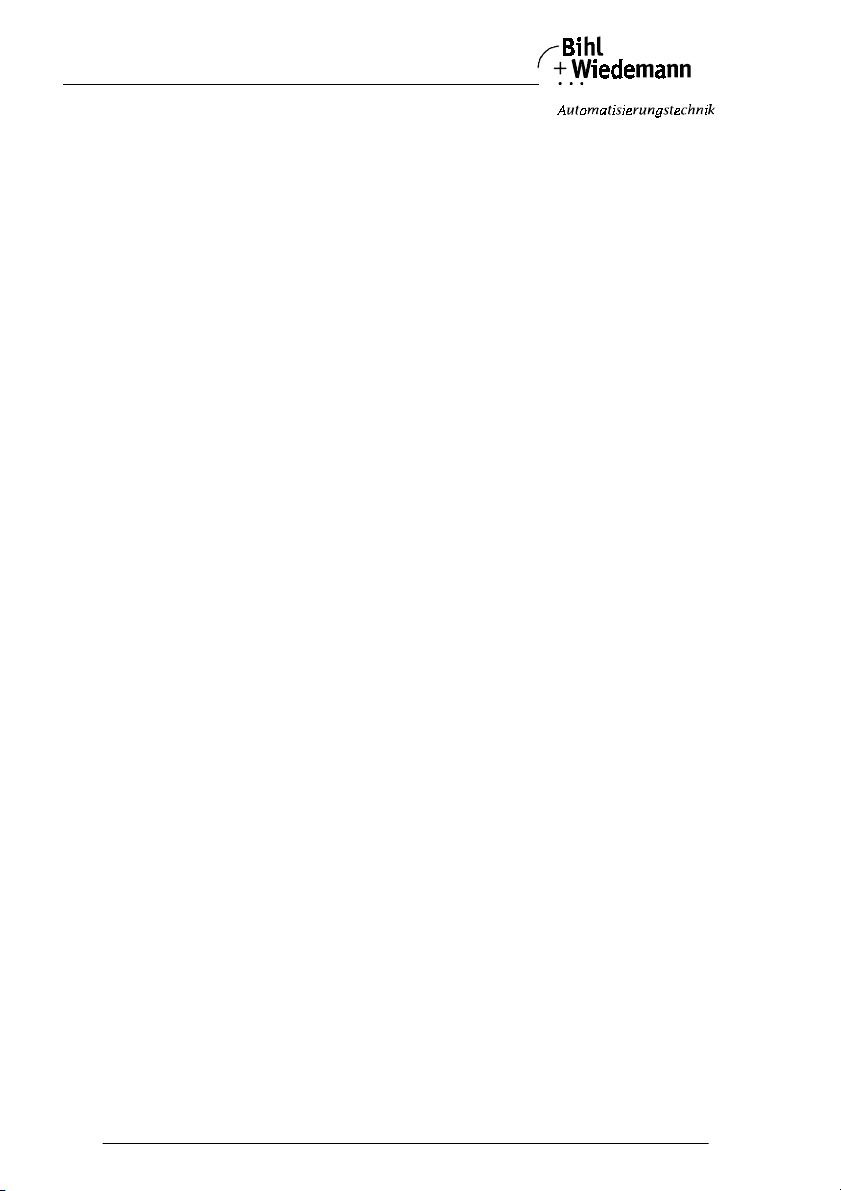
Modules with 2 analog in- or outputs in protection category IP65:
On the front panel of the module are:
• Cage clamp terminals to connect the power supply and for signal in-, respective-
ly outputs
•5 LEDs
• a jumper-block for selecting the connections of power supply (from
AS-Interface, external)
Module with 4 Pt100 Inputs:
On the front panel of the module are:
• Cage clamp terminals for signal inputs
•6 LEDs
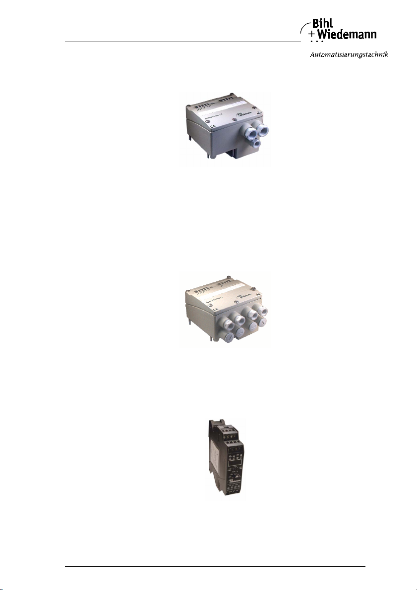
Modules with 2 analog in- or outputs, 2 channels in IP20:
On the front panel of the modules are:
• terminals to connect the power supply and for signal in-, respectively outputs.
issue date 20.1.20 04
Subject to reas onable modifications due to technical advances Copyright Bihl+ Wiedemann, Printed in Germa ny
Bihl+W iedemann GmbH · D -68199 Mannh eim · Phone +49-62 1-339960 · Fax +49 -621-3392239 · I nternet http://w ww.bihl-wiedeman n.de
•6 LEDs
15
Page 16
AS-Interface Analog Module Connections, Displays and Operating Keys
• a slide switch for the selecetion of the power supply (out of As-i, extern).
• a slide switch for the turn on or off of the 2. channel (only input module, see
chapter 5.2.4).
Automatic signal detection:
The input module detects automatically, if there is a current or a voltage signal at
the input. On a input module even current and voltage signals can be connected
combined.
By the output module can be defined with the help of the AS-Interface parameters,
if the AS-Interface analog output module should detect the respective output
modus automatic or it is set by the use of the AS-Interface parameter bits P1 respectively P3.
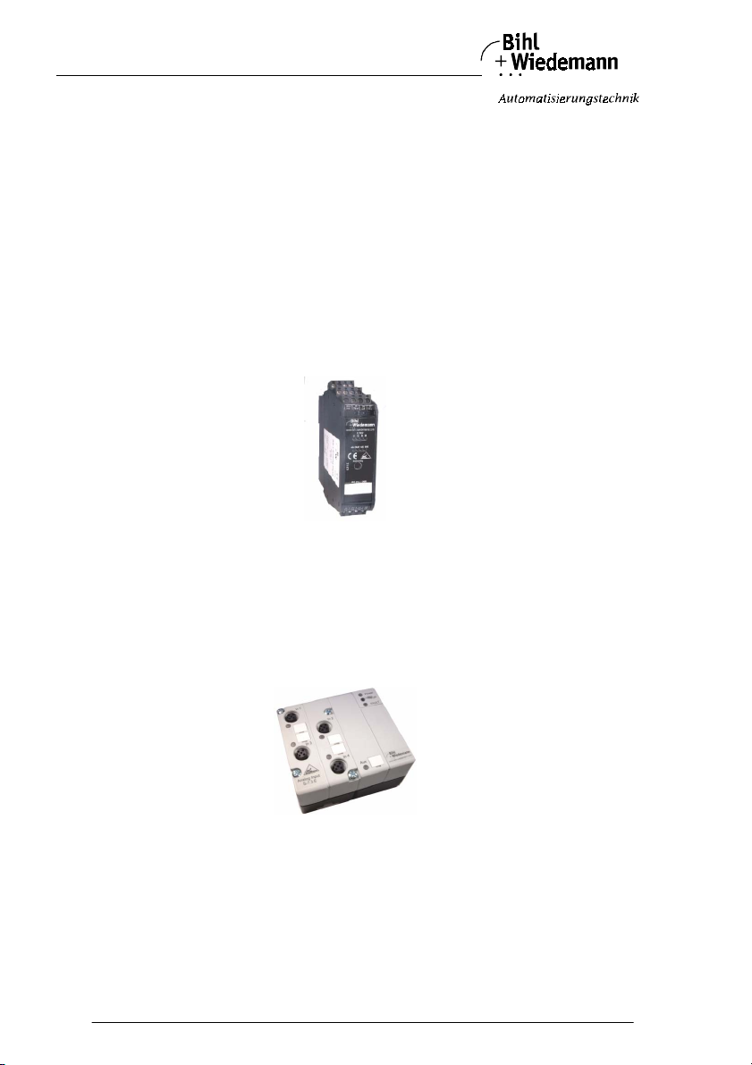
Modules with 4 analog in-, outputs or 4 Pt100 inputs in IP 20:
On the front panel of the modules are:
• terminals to connect the power supply and for signal in-, respectively outputs.
• 8 LEDs (input/output modules)
• 6 LEDs (Pt100)
Modules with 4 analog In-, Outputs or 4 Pt100 Inputs in IP65 with M12 Connection:
On the front panel of the modules are:
• M12 socket for power supply and the in- and output signals of the sensors/actuators
• AS-Interface and external help voltage via the AS-Interface substructure modules
• Addressing of slaves also via infrared interface
•7 LEDs
Subject to reasonable modifications due to technical advances Copyright Bihl+Wiedemann, Printed in Germany
16
Bihl+W iedemann GmbH · D -68199 Mannh eim · Phone +49-62 1-339960 · Fax +49 -621-3392239 · I nternet http://w ww.bihl-wiedemann .de
issue date 20.1.20 04
Page 17
AS-Interface Analog Module Connections, Displays and Operating Keys
4.1 Analog Modules in IP65
4.1.1 Power Supply of Analog Modules in IP65
Analog modules offer the possibilities to supply the attached sensors/actuators either via AS
-
Interface or via external help voltage
24 V. The choice is made with the jumpers inside the module. The
substructure module has to be selected according to the variant of
power supply connection - supply by AS
voltage by 24 V - that is chosen.
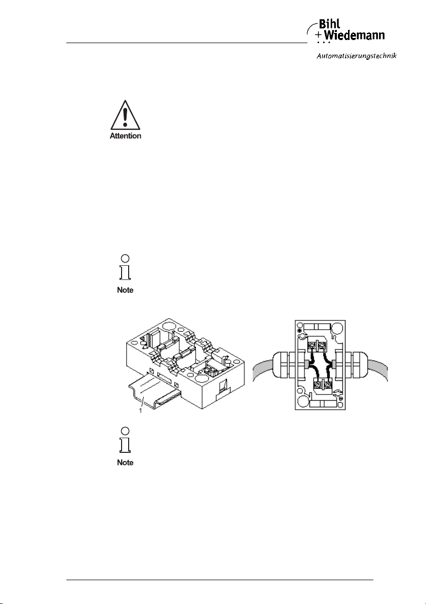
The analog module is attached to the AS-interface by using the electromechanical
interface EMS or the expanded electromechanical interface EEMS.
4.1.1.1 Supplying the Sensors/Actuators by AS-Interface
If the voltage supply of the sensors which are to be attached shall be maintained
by AS-Interface, please use the AS-Interface substructure module (article no.
1180) to connect 2 AS-Interface flat cables, respectively the AS-Interface substructure module (article no. 1182) to connect round cables.
If sensors/actuators are supplied by AS-Interface, the sum must not
exceed 90 mA.
-
Interface or external help
The AS-Interface Pt100 module can only be powered by
AS-Interface.
4.1.1.2 Supplying the Sensors/Actuators by external Help Voltage 24 V
If the sum of energy that is needed to supply the sensors/actuators exceeds 90 mA
an additional auxiliary power-transmission line must be attached to the analog
module.
To do so, please use the AS-Interface substructure module (article no. 1181) to
connect 1 AS-Interface flat cable and 1 flat cable for external help voltage, respec-
issue date 20.1.20 04
Subject to reas onable modifications due to technical advances Copyright Bihl+ Wiedemann, Printed in Germa ny
Bihl+W iedemann GmbH · D -68199 Mannh eim · Phone +49-62 1-339960 · Fax +49 -621-3392239 · I nternet http://w ww.bihl-wiedeman n.de
tively the AS-Interface substructure module (article no. 1183) to connect 1 AS-In-
17
Page 18
AS-Interface Analog Module Connections, Displays and Operating Keys
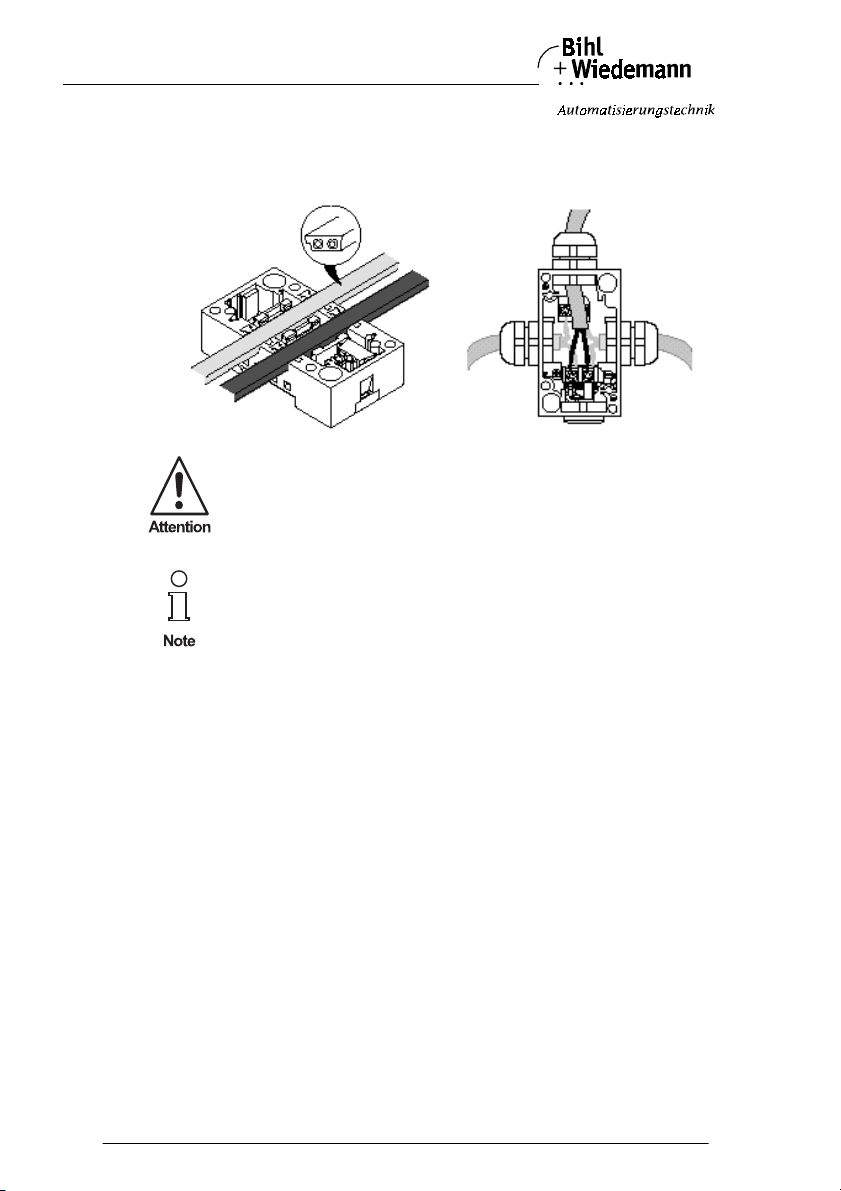
terface round cable and 1 round cable for external help voltage. The external help
voltage are connected by using a connection block which is stuck into the substructure module.
If an external supply is used, the power supply must be according to
PELV (ProtectiveExtra Low Voltage EN 50178).
The substructure module is not included in delivery and must be
ordered separately.
Subject to reasonable modifications due to technical advances Copyright Bihl+Wiedemann, Printed in Germany
18
Bihl+W iedemann GmbH · D -68199 Mannh eim · Phone +49-62 1-339960 · Fax +49 -621-3392239 · I nternet http://w ww.bihl-wiedemann .de
issue date 20.1.20 04
Page 19
AS-Interface Analog Module Connections, Displays and Operating Keys
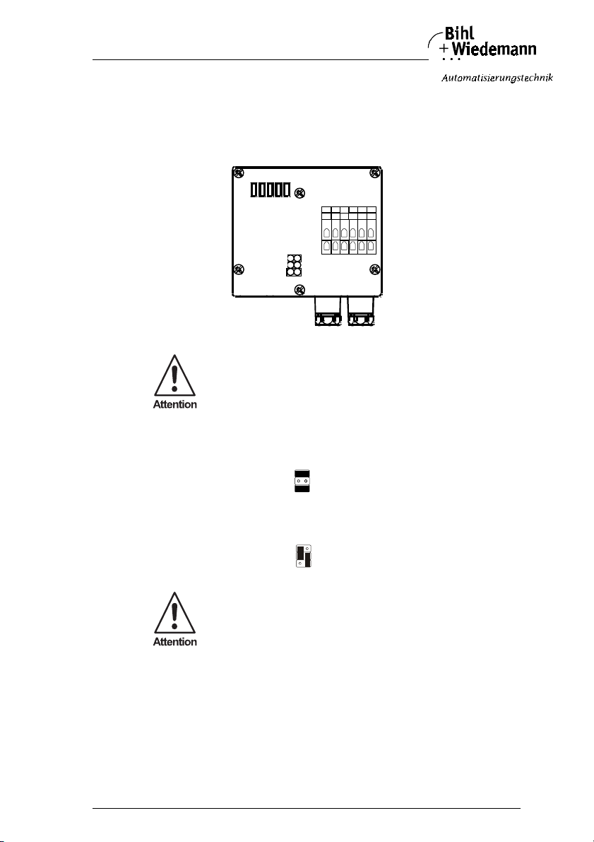
4.1.1.3 Positioning of Jumpers (Input-/Output Modules)
By means of the jumpers, the choice is made whether the sensors/actuators of the
modules with 2 inputs, respectively 2 outputs are supplied by AS-Interface or by a
external help voltage. In order to attach the sensors/actuators and to put the jumpers into the right position, the cover of the analog module must be opened.
LEDs
Jumper
Jumpers shall only be put or pulled in unpowered condition.
If the attached sensors and actuators are supplied by AS-Interface, the following
position of jumpers must be used:
If the attached sensors and actuators are supplied by external help voltage, the following position of jumpers must be used:
If the sensors are supplied by AS-Interface, only AS-Interface cable
must be used in the substructure module. A cable for external help
voltage must not be used in this case.
1
7
24V AS-i
24V ext.
Cage c lamp term inals
2
3
4
5
6
8
9
10
11
12
issue date 20.1.20 04
Subject to reas onable modifications due to technical advances Copyright Bihl+ Wiedemann, Printed in Germa ny
Bihl+W iedemann GmbH · D -68199 Mannh eim · Phone +49-62 1-339960 · Fax +49 -621-3392239 · I nternet http://w ww.bihl-wiedeman n.de
19
Page 20
AS-Interface Analog Module Connections, Displays and Operating Keys
4.1.2 Display- and Operating Elements of Analog Modules
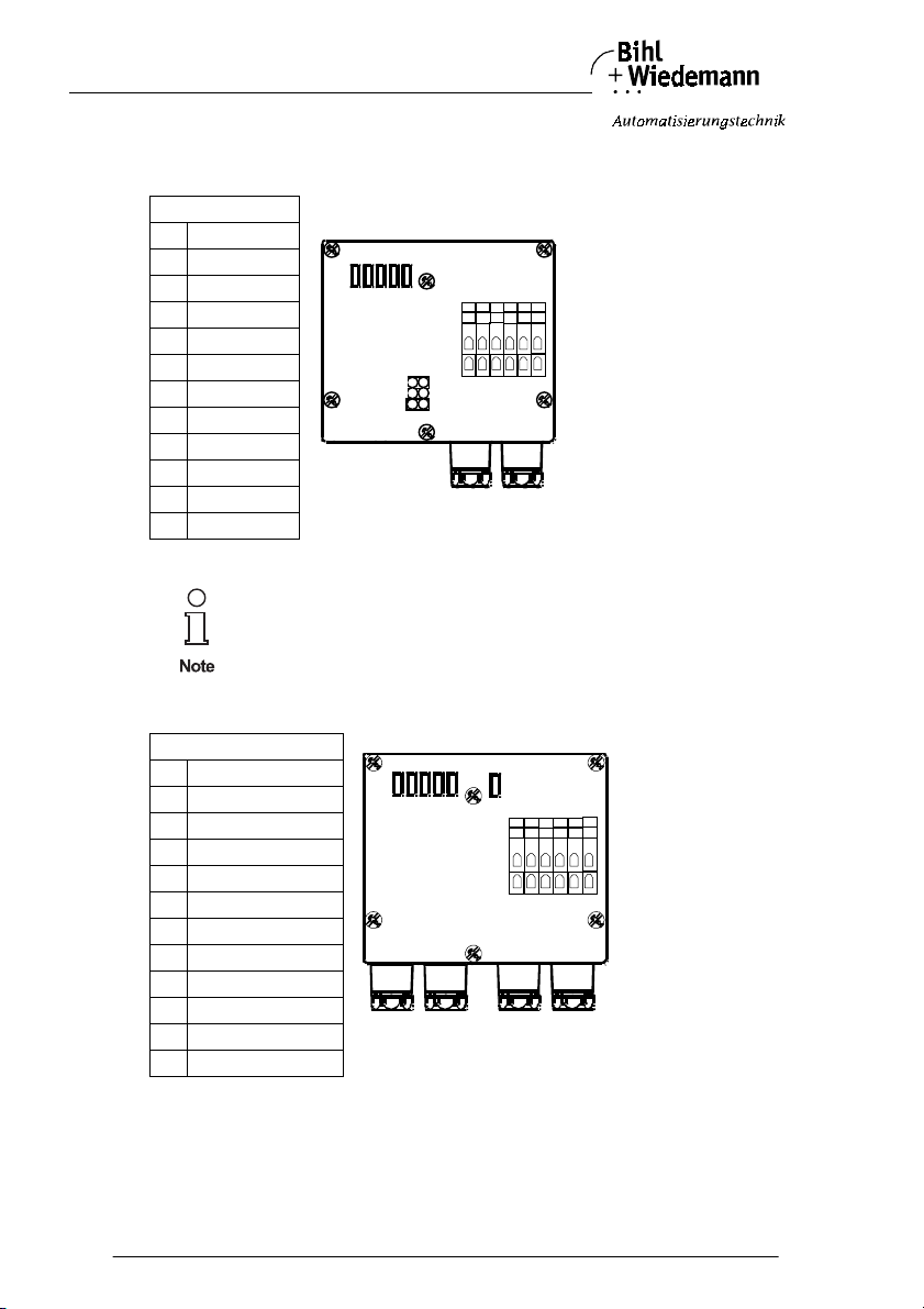
4.1.2.1 Input or Output Modules
Connections
1 24 V ext.
2Sig.+ Ch2
30V ext.
4 Sig.- Ch2
5 Shield
6 Shield
7 24 V ext.
8Sig.+ Ch1
90V ext.
10 Sig.- Ch1
11 F G
12 FG
FG: Function ground for EMC reasons.
For prevention of a periphery fault by an unsed channel 2 of the
input current module
between terminals 1 - 2 a 5,6 kOhm resistor,
between terminals 3-4 a bridge must be connected.
LEDs
Jumper
Cage c lamp term inals
1
7
2
3
4
5
6
8
9
10
11
12
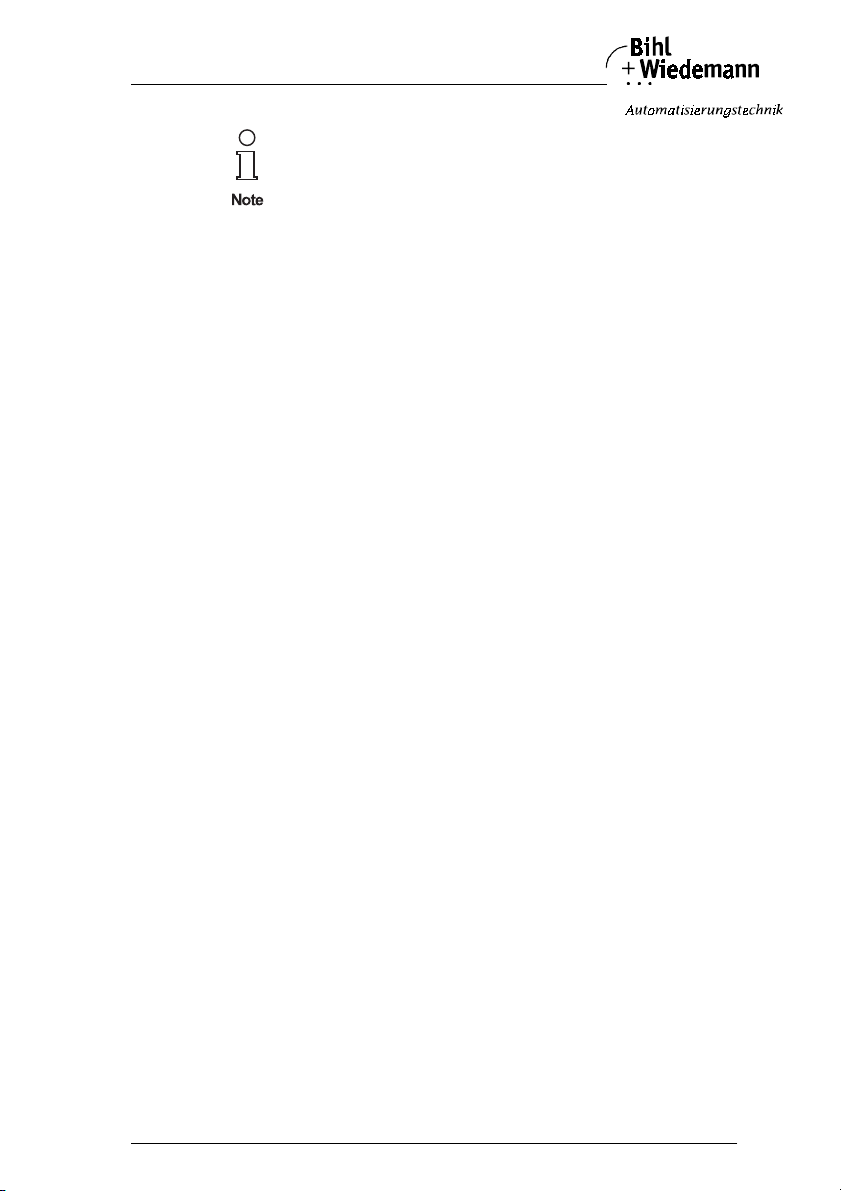
4.1.2.2 Pt100 Module
Connections:
1 Channel 1+
2 Channel 1 Sense-
3 Channel 1-
4 Channel 2+
5 Channel 2 Sense-
6 Channel 2-
7 Channel 3+
8 Channel 3 Sense-
9 Channel 3-
10 Channel 4+
11 Channel 4 Sense-
12 Channel 4-
1,4,7,10 are connected internally.
Subject to reasonable modifications due to technical advances Copyright Bihl+Wiedemann, Printed in Germany
20
Bihl+W iedemann GmbH · D -68199 Mannh eim · Phone +49-62 1-339960 · Fax +49 -621-3392239 · I nternet http://w ww.bihl-wiedemann .de
LEDs
Cage clamp terminal
1 2 3 4
7 8 9 10
5
6
11
12
issue date 20.1.20 04
Page 21
AS-Interface Analog Module Connections, Displays and Operating Keys
For prevention of a periphery fault by unsed channels 2, 3 and/or 4
for channel 2 between terminals 4 - 6 a 220 Ohm resistor,
for channel 3 between terminals 7 - 9 a 220 Ohm resistor,
for channel 4 between terminals 10 - 12 a bridge must be connected.
4.1.2.3 LEDs of Input-/Output Modules
Analog 1 green: off: analog signal not attached (only current input
modules)
on: analog signal within range of values
flashing: analog signal outside range of values
Analog 2 green off: analog signal not attached (only current input
modules)
on: analog signal within range of values
flashing: analog signal outside range of values
Power green on: voltage for analog part OK
AS-i green on: voltage on AS-Interface terminals OK
FAULT red on: AS-Interface communication fault
flashing: peripheral fault
A peripheral fault is shown when at least one of the
signals Analog 1 or Analog 2 is outside the range of
values.
4.1.2.4 LEDs of Pt100 Module
Analog 1 green: off: analog signal not attached
on: analog signal within measuring range
flashing: analog signal outside measuring range
Analog 2 green off: analog signal not attached
on: analog signal within measuring range
flashing: analog signal outside measuring range
Analog 3 green off: analog signal not attached
on: analog signal within measuring range
flashing: analog signal outside measuring range
PWR green on: voltage on AS-Interface terminals OK
FAULT red on: AS-Interface communication fault
flashing: peripheral fault
A peripheral fault is shown when at least one of the
signals Analog 1, Analog 2, Analog 3 or Analog 4 is
outside the measuring range or at least one of the
analog channels is unattached.
Analog 4 green off: analog signal not attached
on: analog signal within measuring range
flashing: analog signal outside measuring range
issue date 20.1.20 04
Subject to reas onable modifications due to technical advances Copyright Bihl+ Wiedemann, Printed in Germa ny
Bihl+W iedemann GmbH · D -68199 Mannh eim · Phone +49-62 1-339960 · Fax +49 -621-3392239 · I nternet http://w ww.bihl-wiedeman n.de
21
Page 22
AS-Interface Analog Module Connections, Displays and Operating Keys
4.2 Analog Modules in IP20 with 2 Channels
4.2.1 Supplying the Sensors/Actuators
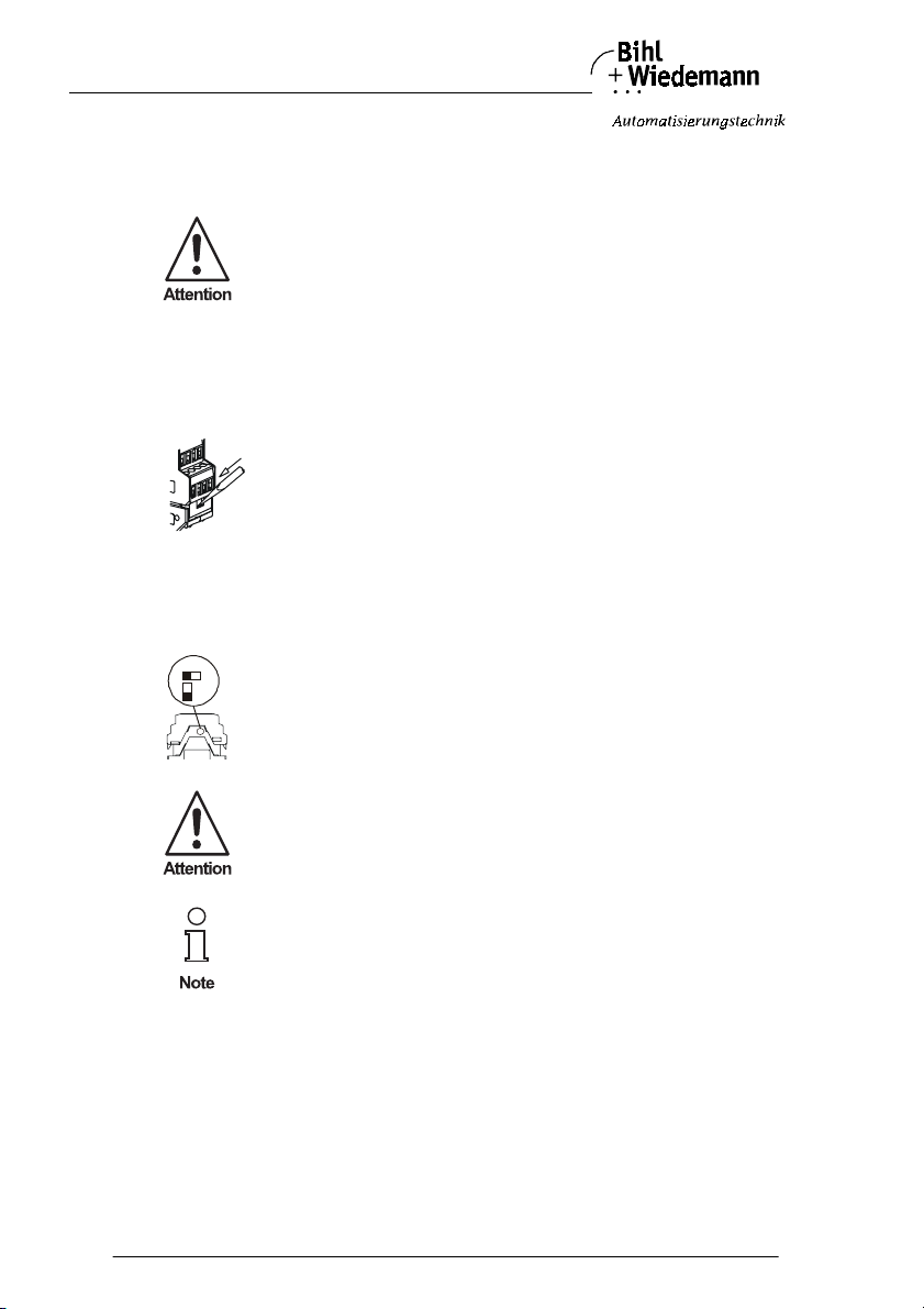
The analog modules offer the possibility to supply the sensors out of
AS-Interface or from external help voltage. This is slected by a
switch inside the module.
Therefore the case of the module has to be opened as follows and the switch to
be adjusted:
1. Unlocking of the module´s top
On both sides of the module force the unlock buttons with help of
a screw driver.
2. Openning the module
Pull out the top until stop
3. Adjusting of the supply
EXT: Power supply of the analog part and of the actuators/sensors
EXT
INT
out of external voltage.
INT: Power supply of the analog part and of the actuators/sensors
out of AS-Interface.
The switch may be actuated by power-off only.
The recognition of a signal type follows after a power reset.
The analog module is connected by clamp terminals to AS-Interf ace. The external
help voltage can be connectd by clamps.
Subject to reasonable modifications due to technical advances Copyright Bihl+Wiedemann, Printed in Germany
22
Bihl+W iedemann GmbH · D -68199 Mannh eim · Phone +49-62 1-339960 · Fax +49 -621-3392239 · I nternet http://w ww.bihl-wiedemann .de
issue date 20.1.20 04
Page 23
AS-Interface Analog Module Connections, Displays and Operating Keys
4.2.2 Display- and Operating Elements
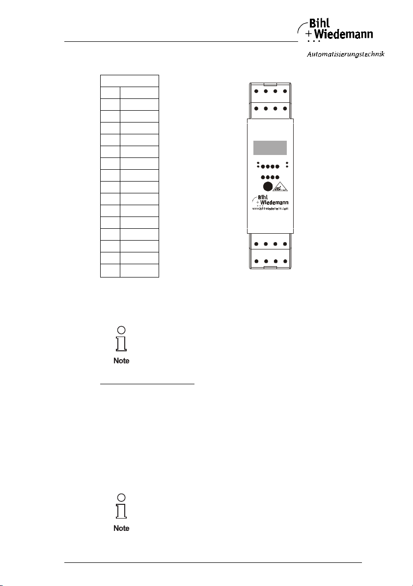
Connections:
1I1 Sig.+
2I1 Sig.-
3 24 V ext.
40V ext.
5I2 Sig.+
1 2 3 4
5 6 7 8
I1
Sig+I1Sig-
I2
Sig+I2Sig-
6I2 Sig.-
7 24 V ext.
–
OK I
80V ext.
9U1 Sig.+
Addr
10 U1 Sig.-
11 U2 Si g.+
12 U2 Sig.-
13 AS-i+
14 AS-i-
15 AUX+
U1
Sig+
AS-i+ AS-i- Aux+ Aux-
9 10 11 12
13 14 15 16
16 AUX-
Input module:
The input currents and voltages are connected via the appropriate terminals (terminals 1, 2/5, 6 respect. 9,10/11, 12).
Not used input channels have to be brigded between Sig. + and
Sig. -.
24V
ext.0Vext.
24V
ext.0Vext.
Output
1212
U
Fault
Int
Pwr
Aux
U2
U2
U1
Sig-
Sig+
Sig-
Automatic signal detection:
The input module detects automatically by turn on, if there is an current or a voltage signal at the input.
On a input module even current and voltage signals can be connected combined.
According to the adjacent current respectively voltage signal the module works in
the correspondening mode.
I
: > 1 mA: Mode current module
nput
: > 1 V: Mode voltage module
U
Input
else: The module works in the at least detected configuration
A channel input can process only either a current or a voltage signal
issue date 20.1.20 04
Subject to reas onable modifications due to technical advances Copyright Bihl+ Wiedemann, Printed in Germa ny
Bihl+W iedemann GmbH · D -68199 Mannh eim · Phone +49-62 1-339960 · Fax +49 -621-3392239 · I nternet http://w ww.bihl-wiedeman n.de
23
Page 24
AS-Interface Analog Module Connections, Displays and Operating Keys
if a current and a voltage signal are connected to one channel input
at the same time, the module and the signal transmitters will be
destroyed.
According to the position of switch S2 the second channel can be switched on or
off (see chapter 5.2.2.1))
The analog modules in IP20 with 2 channels can be used as current
or voltage modules optionally.
The recognition of the signal type follows after a power reset.
Output module:
The output currents and voltages are connected via the appropriat e terminals (terminals 1, 2/5, 6 respect. 9,10/11, 12).
Not used output channels have to be open and not to be brigded.
Automatic signal detection:
The output module detects automatically, if it has to deliver current or voltage (requirements: AS-Interface parameter bit P0 = 1, see chapter 5.3.2.2).
On a output module even current and voltage output signals can be connected
combined. According to the adjacent current respectively voltage signal the module works in the correspondening mode:
At a channel output may be connected only either a current or a voltage signal processing actuator.
If the input data is greater as 1000 by turning on and the voltage at the measuring
resistor of the current output is greater as 100 mV: Current module, else voltage
module.
If the input data is smaller as 1000 by turning on, the module works in the at least
detected configuration.
Subject to reasonable modifications due to technical advances Copyright Bihl+Wiedemann, Printed in Germany
24
Bihl+W iedemann GmbH · D -68199 Mannh eim · Phone +49-62 1-339960 · Fax +49 -621-3392239 · I nternet http://w ww.bihl-wiedemann .de
issue date 20.1.20 04
Page 25

AS-Interface Analog Module Connections, Displays and Operating Keys
4.2.3 LEDs of Input-/Output Modules
PWR green on: Voltage on AS-Interface terminals OK
FAULT red on: AS-Interface communication fault
flashing: peripheral fault
A peripheral fault is shown when at least
one of the signals Input 1/Output 1 or
Input 2/Output 2 is outside the range of
values.
AUX green on: 24 V supply for analog part OK
INT green on: Voltage supply out of AS-Interface for
an-
alog part OK
Input 1/Output 1 -/OK green: off: Analog signal not attached (only current
input module)
on: A nalog signal within range of values
flashing: A nalog signal outside range of values
Input 2/Output 2 -/ OK green off: Analog signal not attached (only current
input module)
on: A nalog signal within range of values
flashing: A nalog signal outside range of values
Input 1/Output 1 U/I green: off: Voltage in-/output
on: Current in-/output
Input 2/Output 2 U/I green off: Voltage in-/output
on: Current in-/output
issue date 20.1.20 04
Subject to reas onable modifications due to technical advances Copyright Bihl+ Wiedemann, Printed in Germa ny
Bihl+W iedemann GmbH · D -68199 Mannh eim · Phone +49-62 1-339960 · Fax +49 -621-3392239 · I nternet http://w ww.bihl-wiedeman n.de
25
Page 26
AS-Interface Analog Module Connections, Displays and Operating Keys
4.3 Analog Modules in IP20 with 4 Channels
4.3.1 Power supply of Analog Modules
The analog modules (except Pt100 module) offer the possibilities to
supply the attached sensors/actuators either via AS
external help voltage. As soon as the external help voltage is fitted,
the sensors/actuators will be supplied automatically out of the external help voltage.
The sensors/actuators and AS-Interface are galvanical separated
yet.
The analog modules are conntected by clamp terminals to the AS-interface. The
external help voltage is connected by clamps.
4.3.2 Display and Operating Elements
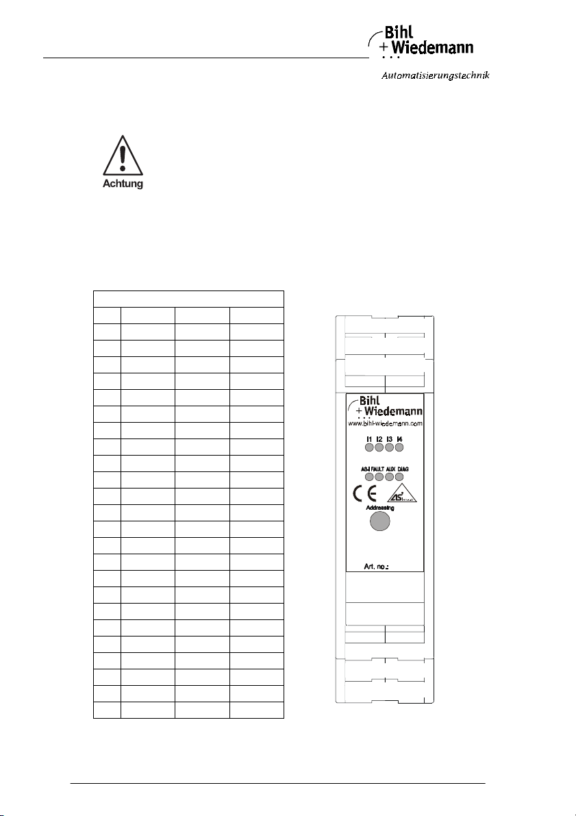
Connections
pin input output 4 Pt100
1 24 V ext. 24 V ext. FE
2 I1 Sig.+ O1 Sig.+ FE
3 0 V ext. 0 V ext. FE
4 I1 Sig.- O1 Sig.- FE
5 24 V ext. 24 V ext. CHS1+
6 I2 Sig.+ O2 Sig.+ CH1+
7 0 V ext. 0 V ext. CH1-
8 I2 Sig.- O2 Sig.- CHS1-
9 24 V ext. 24 V ext. CHS2+
10 I3 Sig.+ O3 Sig.+ CH2+
11 0 V ext. 0 V ext. CH2-
12 I3 Sig.- O3 Sig.- CHS2-
13 I4 Sig.- O4 Sig.- CHS3-
14 0 V ext. 0 V ext. CH3-
15 I4 Sig.+ O4 Sig.+ CH3+
16 24 V ext. 24 V ext. CHS3+
17 n. c. n. c. CHS4-
18 n. c. n. c. CH4-
19 n. c. n. c. CH4+
20 n. c. n. c. CHS4+
21 AS-i+ AS-i+ AS-i+
22 AS-i- AS-i- AS-i-
23 AUX+ AUX+ n. c.
24 AUX- AUX- n. c.
-
Interface or via
1 2 3 4
5 6 7 8
9 10 11 12
13 14 15 16
17 18 19 20
21 22 23 24
Subject to reasonable modifications due to technical advances Copyright Bihl+Wiedemann, Printed in Germany
26
Bihl+W iedemann GmbH · D -68199 Mannh eim · Phone +49-62 1-339960 · Fax +49 -621-3392239 · I nternet http://w ww.bihl-wiedemann .de
issue date 20.1.20 04
Page 27

AS-Interface Analog Module Connections, Displays and Operating Keys
4.3.2.1 Input Modules
The input currents or voltages respectively are connected via the appropriate terminals (terminals 2/ 4. 6/8, 10/12, 15/13).
4.3.2.2 Output Modules
Via the appropriate terminals (terminals 2/4. 6/8, 10/12, 15/13) the output currents
or voltages respectively are provided.
4.3.2.3 Pt100 Module
A 2-wire-sensor is attached to terminals 6/7, 10/11, 15/14, 19/18.
A 4-wire-sensor is attached to following terminals: Channel 1 9 + 10/12 + 11,
channel 2 10 + 9/11 + 12, channel 3 15 + 16/14 + 13, channel 4 19 + 20/18 + 17.
issue date 20.1.20 04
Subject to reas onable modifications due to technical advances Copyright Bihl+ Wiedemann, Printed in Germa ny
Bihl+W iedemann GmbH · D -68199 Mannh eim · Phone +49-62 1-339960 · Fax +49 -621-3392239 · I nternet http://w ww.bihl-wiedeman n.de
27
Page 28
AS-Interface Analog Module Connections, Displays and Operating Keys
4.3.3 LEDs of Input-/Out put Modules
The term of displaying the state of the channels 1 - 4 of the input modules and of
the Pt100 module are I1, I2, I3 and I4; for the output modules O1, O2, O3, O4.
AS-I green on: Voltage on AS-Interface terminals OK
FAULT red on: AS-Interface communication fault
flashing: Peripheral fault
A peripheral fault is shown when at least one of the
signals 1/O1, I2/O2, I3/O3 oder I4/O4 is outside the
range of values.
AUX green on: External help voltage for analog part OK
DIAG green on: Diagnosis
I1/O1 yellow on: Analog signal within range of values
flashing: Analog signal outside range of values
I2/O2 yellow off: Cannel is switched off (only input modules)
on: Analog signal within range of values
flashing: Analog signal outside range of values
I3/O3 yellow off: Cannel is switched off (only input modules)
on: Analog signal within range of values
flashing: Analog signal outside range of values
I4/O4 yellow off: Cannel is switched off (only input modules)
on: Analog signal within range of values
flashing: Analog signal outside range of values
Subject to reasonable modifications due to technical advances Copyright Bihl+Wiedemann, Printed in Germany
28
Bihl+W iedemann GmbH · D -68199 Mannh eim · Phone +49-62 1-339960 · Fax +49 -621-3392239 · I nternet http://w ww.bihl-wiedemann .de
issue date 20.1.20 04
Page 29

AS-Interface Analog Module Connections, Displays and Operating Keys
4.3.4 LEDs of Pt100 Module
AS-i green on: voltage on AS-Interface terminals OK
FAULT red on: AS-Interface communication fault
flashing: peripheral fault
a peripheral fault is shown when at least one of the
signals I 1, I 2, I 3 or I 4 is outside the measuring range
or at least one of the analog channels is unattached.
I 1 yellow off: analog signal not attached
on: analog signal within measuring range
flashing: analog signal outside measuring range
I 2 yellow off: analog signal not attached
on: analog signal within measuring range
flashing: analog signal outside measuring range
I 3 yellow off: analog signal not attached
on: analog signal within measuring range
flashing: analog signal outside measuring range
I 4 yellow off: analog signal not attached
on: analog signal within measuring range
flashing: analog signal outside measuring range
issue date 20.1.20 04
Subject to reas onable modifications due to technical advances Copyright Bihl+ Wiedemann, Printed in Germa ny
Bihl+W iedemann GmbH · D -68199 Mannh eim · Phone +49-62 1-339960 · Fax +49 -621-3392239 · I nternet http://w ww.bihl-wiedeman n.de
29
Page 30
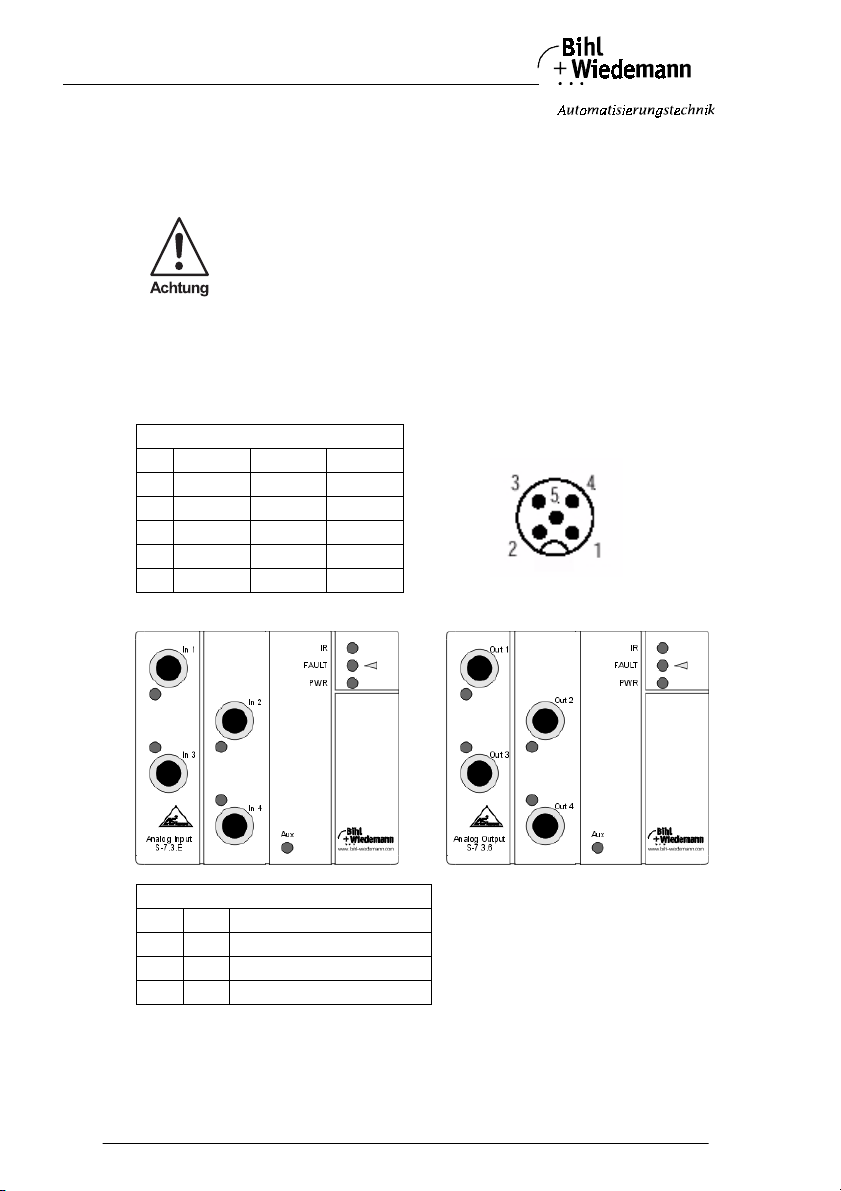
AS-Interface Analog Module Connections, Displays and Operating Keys
4.4 Analog Modules with 4 Channels and M12 Connection in Protection Category IP65
4.4.1 Power supply of Analog Modules
The analog modules (except Pt100 module) offer the possibilities to
supply the attached sensors/actuators either via AS
-
Interface or via
external help voltage. As soon as the external help voltage is fitted,
the sensors/actuators will be supplied automatically out of the external help voltage.
The sensors/actuators and AS-Interface are galvanical separated
yet.
The analog modules are conntected by a substructure module to the AS-I nterface .
4.4.2 Display and Operating Elements
Connections M12 connection
Pin Input Output 4 Pt100
1 24 V ext. Sig. + CH+
2Sig. + n.c. CHS+
3 0 V Sig. - CH-
4Sig. - n.c. CHS-
5 Shield Shield Shield
4.4.2.1 In-/Output Modules
Connection
IN1 OUT M12 connection channel 1
IN2 OUT M12 connection channel 2
IN3 OUT M12 connection channel 3
IN4 OUT M12 connection channel 4
Subject to reasonable modifications due to technical advances Copyright Bihl+Wiedemann, Printed in Germany
30
Bihl+W iedemann GmbH · D -68199 Mannh eim · Phone +49-62 1-339960 · Fax +49 -621-3392239 · I nternet http://w ww.bihl-wiedemann .de
issue date 20.1.20 04
Page 31
AS-Interface Analog Module Connections, Displays and Operating Keys
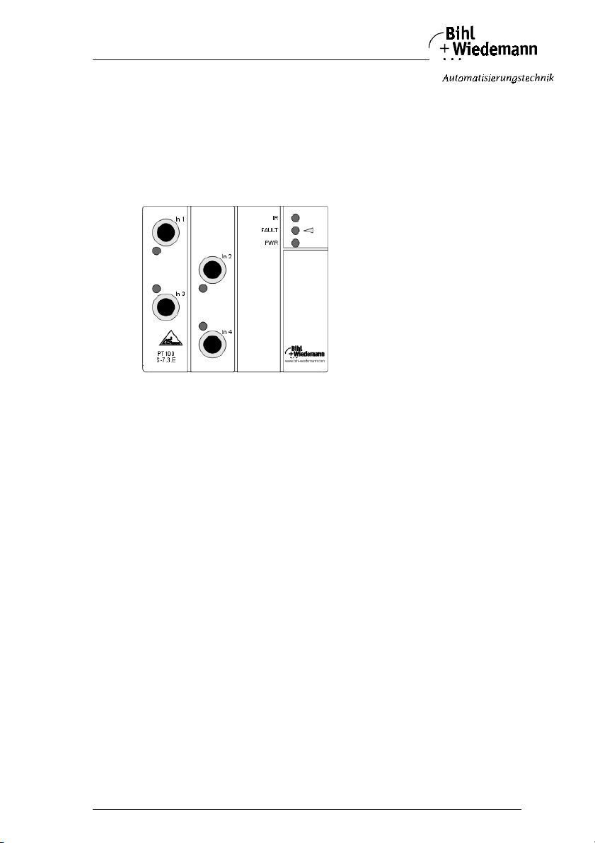
4.4.2.2 Input Modules
The input currents or voltages respectively are connected via the appropriate M12
socket (pins 2, 4).
4.4.2.3 Output Modules
Via the appropriate M12 socket (pins 1,3) the output currents or voltages respectively are provided.
4.4.2.4 Pt100 Module
A 2-wire-sensor is connected via the appropriate M12 socket (pins 1, 3).
A 4-wire-sensor is connected via the appropriate M12 socket (pins 1 + 2/3 + 4).
issue date 20.1.20 04
Subject to reas onable modifications due to technical advances Copyright Bihl+ Wiedemann, Printed in Germa ny
Bihl+W iedemann GmbH · D -68199 Mannh eim · Phone +49-62 1-339960 · Fax +49 -621-3392239 · I nternet http://w ww.bihl-wiedeman n.de
31
Page 32
AS-Interface Analog Module Connections, Displays and Operating Keys
4.4.3 LEDs of Input-/Out put Modules
The term of displaying the state of the channels 1 - 4 of the input modules and of
the Pt100 module are In 1,In 2, In 3 and In 4; for the output modules Out 1, Out 2,
Out 3, Out 4.
PWR green on: Voltage on AS-Interface terminals OK
FAULT red on: AS-Interface communication fault
flashing: Peripheral fault
A peripheral fault is shown when at least one of the
signals 1/O1, I2/O2, I3/O3 oder I4/O4 is outside the
range of values.
AUX green on: External help voltage OK
In 1/Out 1 yellow on: Analog signal within range of values
flashing: Analog signal outside range of values
In 2/Out 2 yellow off: Cannel is switched off (only input modules)
on: Analog signal within range of values
flashing: Analog signal outside range of values
In 3/Out 3 yellow off: Cannel is switched off (only input modules)
on: Analog signal within range of values
flashing: Analog signal outside range of values
In 4/Out 4 yellow off: Cannel is switched off (only input modules)
on: Analog signal within range of values
flashing: Analog signal outside range of values
Subject to reasonable modifications due to technical advances Copyright Bihl+Wiedemann, Printed in Germany
32
Bihl+W iedemann GmbH · D -68199 Mannh eim · Phone +49-62 1-339960 · Fax +49 -621-3392239 · I nternet http://w ww.bihl-wiedemann .de
issue date 20.1.20 04
Page 33

AS-Interface Analog Module Connections, Displays and Operating Keys
4.4.4 LEDs of Pt100 Module
PWR green on: voltage on AS-Interface terminals OK
FAULT red on: AS-Interface communication fault
flashing: Peripheral fault
A Peripheral fault is shown when at least one of the
signals In 1, In 2, In 3 or In 4 is outside the measuring
range or at least one of the analog channels is unattached.
In 1 yellow off: Analog signal not attached
on: Analog signal within measuring range
flashing: Analog signal outside measuring range
In 2 yellow off: Analog signal not attached
on: Analog signal within measuring range
flashing: Analog signal outside measuring range
In 3 yellow off: Analog signal not attached
on: Analog signal within measuring range
flashing: Analog signal outside measuring range
In 4 yellow off: Analog signal not attached
on: Analog signal within measuring range
flashing: Analog signal outside measuring range
issue date 20.1.20 04
Subject to reas onable modifications due to technical advances Copyright Bihl+ Wiedemann, Printed in Germa ny
Bihl+W iedemann GmbH · D -68199 Mannh eim · Phone +49-62 1-339960 · Fax +49 -621-3392239 · I nternet http://w ww.bihl-wiedeman n.de
33
Page 34
AS-Interface Analog Module Connections, Displays and Operating Keys
4.5 Pin Configuration
4.5.1 Analog Modules in IP65 with 2 Channels
In order to improve EMC during signal transmission, the analog sensors and actuators can be attached to the modules with 2 analog inputs, respectively 2 analog
outputs by using shielded cables. Therefore the shielding has to be connected with
pin 5 and 6. Function ground is connected with pin 11 and 12.
4.5.1.1 Pin Configuration of Analog Input Modules in IP65 with 2 Channels
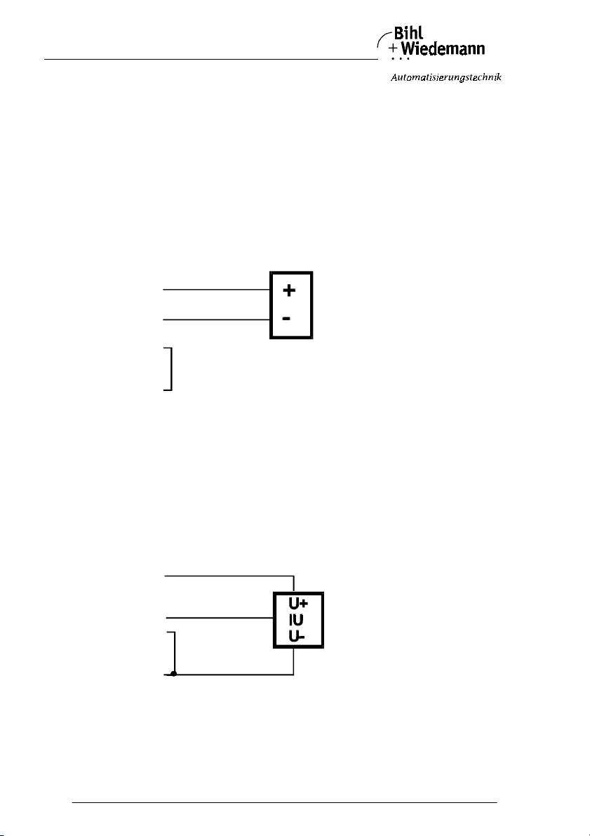
Connection of a 2-wire-sensor to the analog input module in IP65 with 2
channels:
Analog module 2-wire-sensor
24V ext.
Sig.+
Sig.-
0V ext.
A 2-wire-sensor is attached to terminal 7 (24 V) and 8 (Sig.+) of channel 1. Terminals 9 (0 V ext.) and 10 (Sig.-) have to be connected to each other by using a
bridge.
Corresponding channel 2 is attached via terminal 1 (24 V) and 2 (Sig.+) as well as
3 (0 V ext.) and 4 (Sig.-).
Connection of a 3-wire-sensor to the analog input module in IP65 with 2
channels:
Analog module 3-wire-sensor
24V ext.
Sig.+
Sig. -
0V ext.
A 3-wire-sensor is attached to terminal 7 (24 V), 8 (Sig.+) and 9 (0 V ext.) of channel 1. Terminals 9 (0 V ext.) and 10 (Sig.-) have to be connected to each other by
using a bridge.
Corresponding channel 2 is attached via terminal 1 (24 V) and 2 (Sig.+) as well as
3 (0 V ext.) and 4 (Sig.-).
Subject to reasonable modifications due to technical advances Copyright Bihl+Wiedemann, Printed in Germany
34
Bihl+W iedemann GmbH · D -68199 Mannh eim · Phone +49-62 1-339960 · Fax +49 -621-3392239 · I nternet http://w ww.bihl-wiedemann .de
issue date 20.1.20 04
Page 35
AS-Interface Analog Module Connections, Displays and Operating Keys
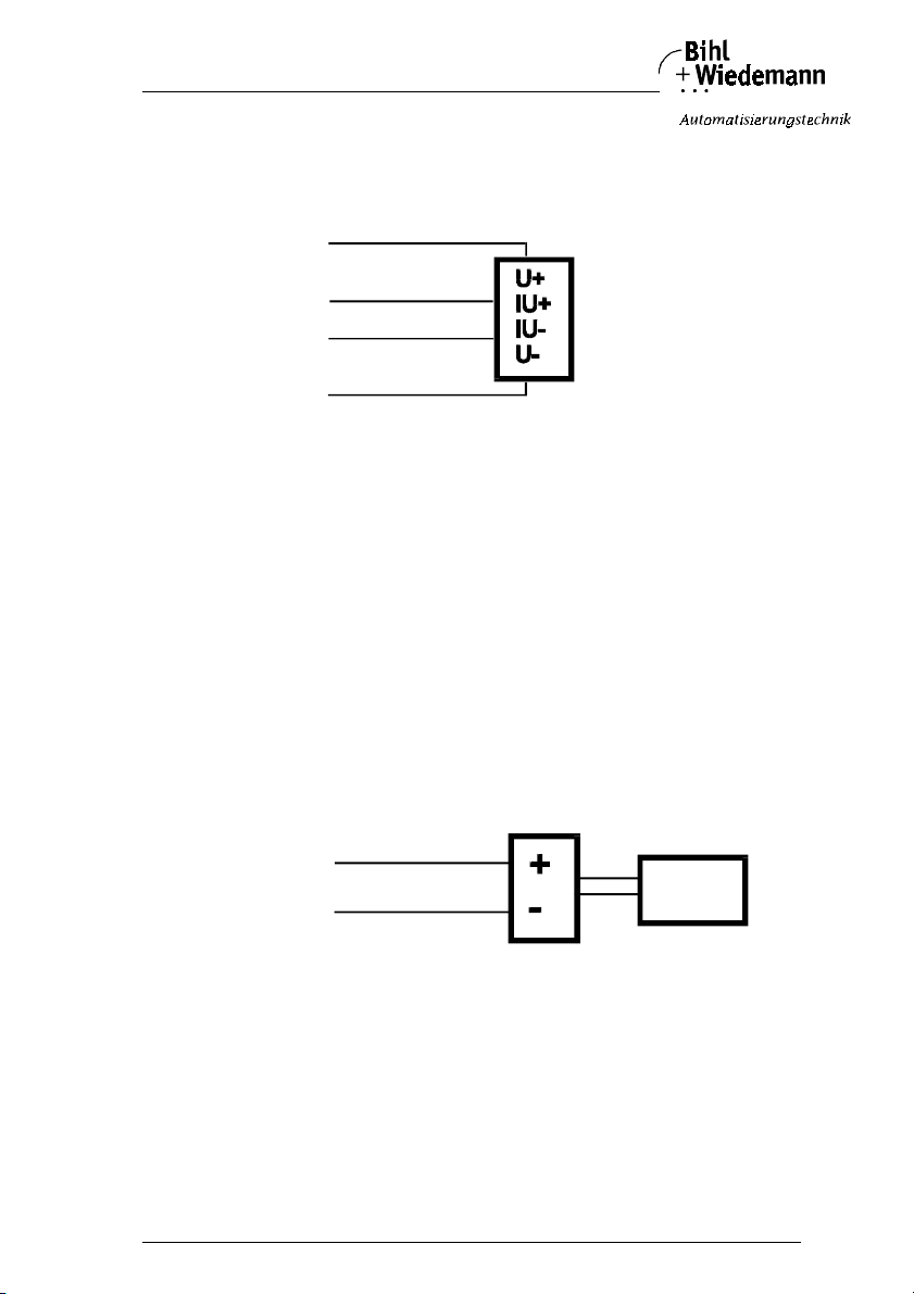
Connection of a 4-wire-sensor to the analog input module in IP65 with 2
channels:
Analog module 4-wire-sensor
24V ext.
Sig.+
Sig.-
GND
A 4-wire-sensor is attached to terminal 7 (24 V), 8 (Sig.+), 9 (0 V ext.) and 10
(Sig.-) of channel 1 (see figure above for details).
Corresponding channel 2 is attached via 1 (24 V) and 2 (Sig.+) as well as 3 (0 V
ext.) and 4 (Sig.-).
Analog input modules with 2 current inputs are delivered with a resistor between
terminals 1 and 2 and a bridge between terminals 3 and 4. With that, it is prevented
that a fault message for input channel 2 is notified by the module when it is brought
into service and only one sensor at input channel 1 is attached.
By using of a sensor at channel 2 the resistor and, if necessary, the bridge have
to be removed.
Connection of a sensor with own power supply to an analog input module in
IP65 with 2 channels:
Analog module Sensor with own power supply
24V ext.
Sig.+
Sig.-
0V ext.
supply PELV
without earth
connection
A sensor with own supply is attached to terminal 8 (Sig.+) and 10 (Sig.-) of
channel 1.
Corresponding channel 2 is attached via 2 (Sig.+) and 4 (Sig.-).
issue date 20.1.20 04
Subject to reas onable modifications due to technical advances Copyright Bihl+ Wiedemann, Printed in Germa ny
Bihl+W iedemann GmbH · D -68199 Mannh eim · Phone +49-62 1-339960 · Fax +49 -621-3392239 · I nternet http://w ww.bihl-wiedeman n.de
35
Page 36
AS-Interface Analog Module Connections, Displays and Operating Keys
4.5.1.2 Pin Configuration of the Analog Output Module (0 … 20 mA) in IP65 with 2 Channels
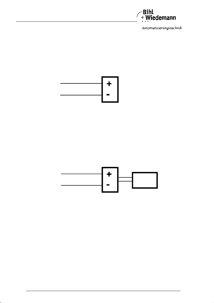
Connection of an actuator without separate power supply to the analog output module (0 … 20 mA) in IP65 with 2 channels:
Analog module Actuator without separate 24 V supply
24V ext.
Sig.+
Sig.-
0V ext.
A 2-wire-actuator is attached to terminal 8 (Sig.+) and 10 (Sig.-) of channel 1.
Corresponding channel 2 is attached via 2 (Sig.+) and 4 (Sig.-).
Connection of an actuator with own power supply to the analog output module (0 … 20 mA) in IP65 with 2 channels:
Analog module Actuator with own power supply
24V ext.
Sig.+
Sig.-
0V ext.
supply PELV
without earth
connection
An actuator with own power supply (e. g. an ampmeter) is attached to terminal 8
(Sig.+) and 10 (Sig.-) of channel 1.
Corresponding channel 2 is attached via 2 (Sig.+) and 4 (Sig.-).
Subject to reasonable modifications due to technical advances Copyright Bihl+Wiedemann, Printed in Germany
36
Bihl+W iedemann GmbH · D -68199 Mannh eim · Phone +49-62 1-339960 · Fax +49 -621-3392239 · I nternet http://w ww.bihl-wiedemann .de
issue date 20.1.20 04
Page 37
AS-Interface Analog Module Connections, Displays and Operating Keys
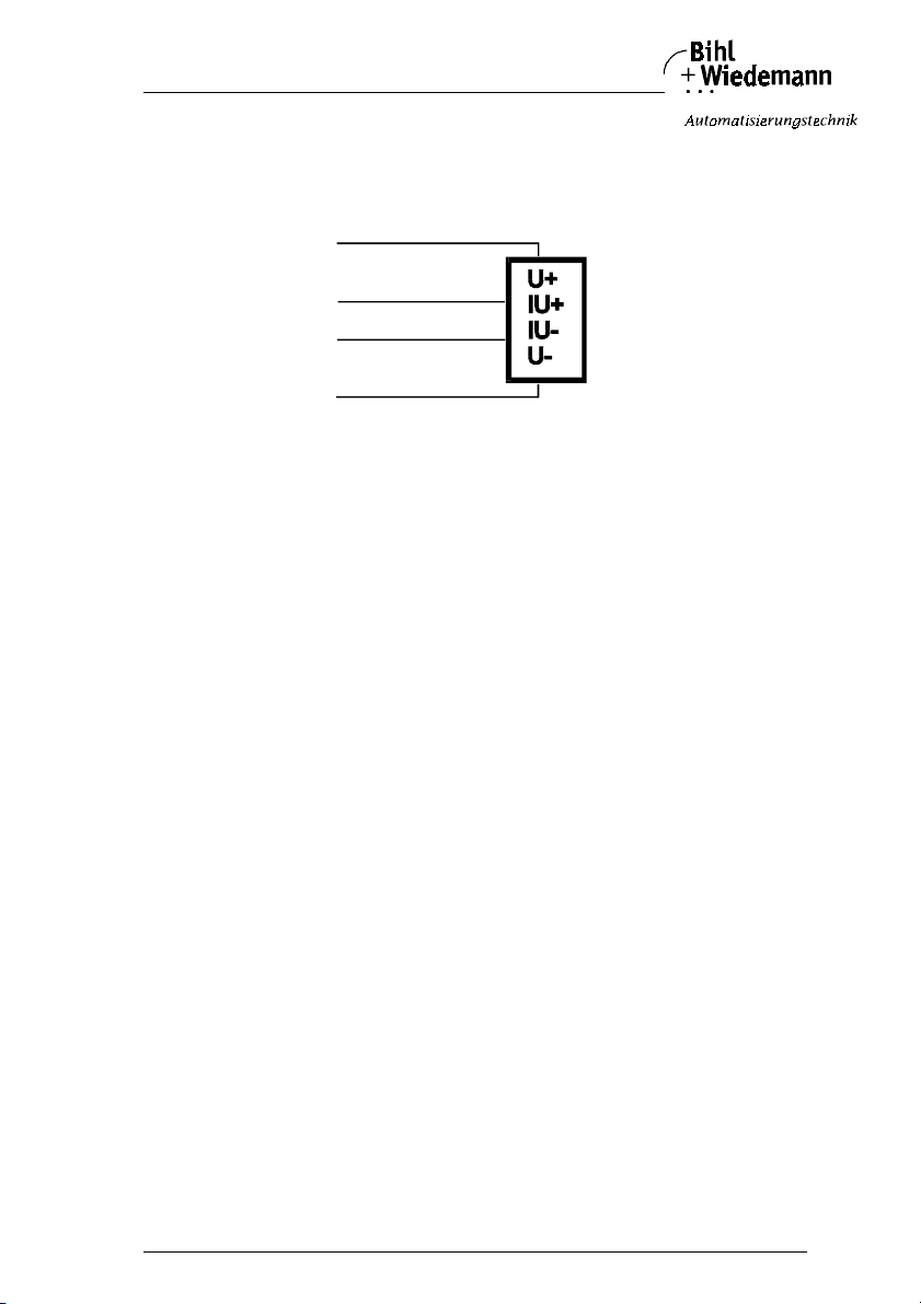
Connection of an actuator with separate 24 V power supply to the analog
output module (0 … 20 mA) in IP65 with 2 ch annels:
Analog module Actuator with separate 24 V power supply
24V ext.
Sig.+
Sig.-
0V ext.
The separate 24 V are attached to terminal 7 (24 V) and 9 (0 V ext.), the analog
signal to terminal 8 (Sig.+) and 10 (Sig.-) of channel 1.
Corresponding channel 2 is attached via terminals 1 (24 V) and 3 (0 V ext.) as well
as 2 (Sig.+) and 4 (Sig.-).
issue date 20.1.20 04
Subject to reas onable modifications due to technical advances Copyright Bihl+ Wiedemann, Printed in Germa ny
Bihl+W iedemann GmbH · D -68199 Mannh eim · Phone +49-62 1-339960 · Fax +49 -621-3392239 · I nternet http://w ww.bihl-wiedeman n.de
37
Page 38
AS-Interface Analog Module Connections, Displays and Operating Keys
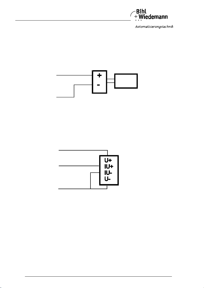
4.5.1.3 Pin Configuration of the Analog Output Module (0 … 10 V) in IP65 with 2 Channels
Connection of an actuator with own power supply to the analog output module in IP65 with 2 channels:
Analog module Actuator with own power supply
24V ext.
Sig.+
Sig.-
supply PELV
without earth
connection
0V ext.
An actuator with own power supply (e. g. a voltmeter) is attached to terminals 8
(Sig.+) and 9 (0 V ext.) of channel 1, as well as terminals 2 (Sig.+) and 3 (0 V ext.)
of channel 2.
Connection of an actuator with separate 24 V power supply to the analog
output module in IP65 with 2 channels:
Analog module Actuator with separate 24 V power supply
24V ext.
Sig.+
Sig.-
0V ext.
The separate 24 V are attached to terminal 7 (24 V) and 9 (0 V ext.), the analog
signal to terminal 8 (Sig.+) and 9 (0 V ext.) of channel 1.
Corresponding channel 2 is attached via terminals 1 (24 V) and 3 (0 V ext.) as well
as 2 (Sig.+) and 3 (0 V ext.).
Subject to reasonable modifications due to technical advances Copyright Bihl+Wiedemann, Printed in Germany
38
Bihl+W iedemann GmbH · D -68199 Mannh eim · Phone +49-62 1-339960 · Fax +49 -621-3392239 · I nternet http://w ww.bihl-wiedemann .de
issue date 20.1.20 04
Page 39
AS-Interface Analog Module Connections, Displays and Operating Keys
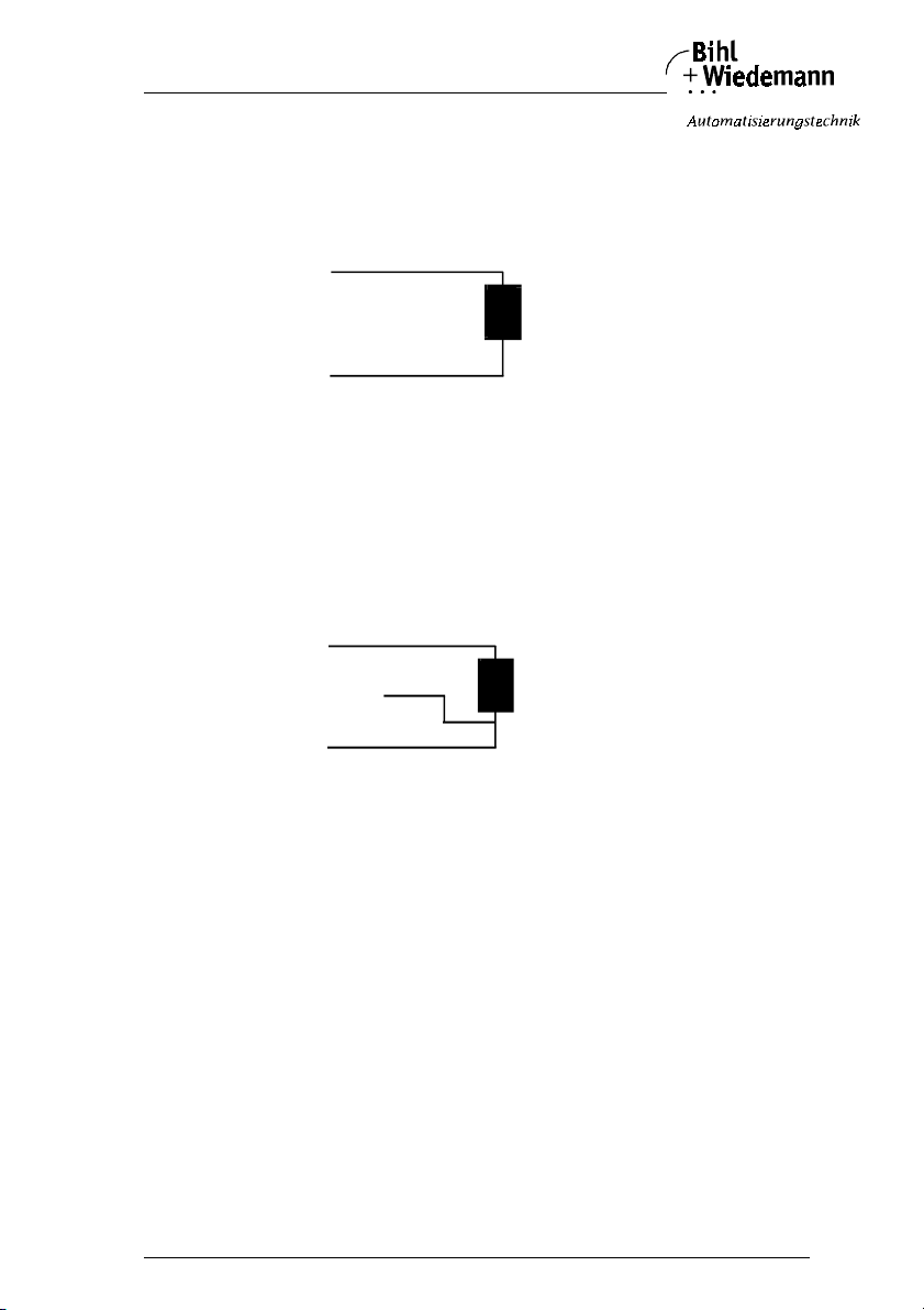
4.5.1.4 Pin Configuration of the AS-Interface Pt100 Module in IP65 with 4 Channels
Connection of a 2-wire-Pt100 element to the AS-Interface Pt100 module in
IP65 with 4 channels:
Analog module Pt100 element
Ch. +
Ch Sense -
Ch -
Channel 1 applies to terminals 1 and 3, channel 2 applies to terminals 4 and 6,
channel 3 applies to terminals 7 and 9 and channel 4 applies to terminals 10 and
12.
Terminals 1, 4, 7 and 10 (Ch. +) are interconnected inside the module.
Connection of a 3-wire-Pt100 element to the AS-Interface Pt100 module in
IP65 with 4 channels:
Analog module Pt100 element
Ch. +
Ch Sense -
Ch -
Channel 1 applies to terminals 1 - 3, channel 2 applies to terminals 4 - 6, channel
3 applies to terminals 7 - 9 and channel 4 applies to terminals 10 - 12.
Terminals 1, 4, 7 and 10 (Ch. +) are interconnected inside the module.
3-wire-Pt100 sensors yield better results than 2-wire-sensors. For this, the feed
lines must be equal in resistance.
Switching between 3- and 2-wire-sensors takes place via AS-Interface parameter
bit 3.
The Pt100 moduls are deliverd with resistors between terminal 4 and 6, 7 and 9 as
well as 10 and 12. With that it is prevented that a fault message is notified by the
module when it is brought into service and only one sensor is attached.
issue date 20.1.20 04
Subject to reas onable modifications due to technical advances Copyright Bihl+ Wiedemann, Printed in Germa ny
Bihl+W iedemann GmbH · D -68199 Mannh eim · Phone +49-62 1-339960 · Fax +49 -621-3392239 · I nternet http://w ww.bihl-wiedeman n.de
39
Page 40
AS-Interface Analog Module Connections, Displays and Operating Keys
4.5.2 Analog Modules in IP20 with 2 Channels
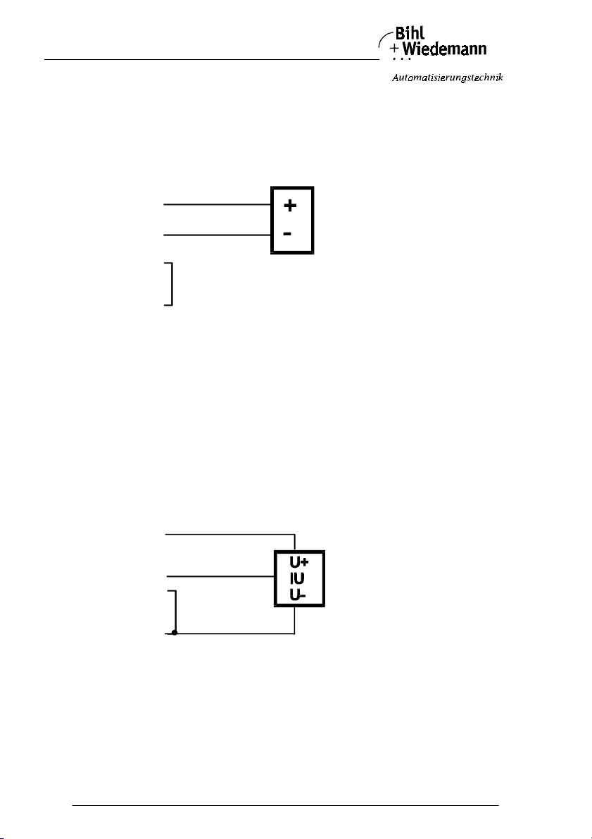
4.5.2.1 Pin Configuration of Analog Input Modules in IP20 with 2 Channels
Connection of a 2-wire-sensor to the analog input module in IP20 with 2
channels:
Analog module 2-wire-sensor
24V ext.
Sig.+
Sig.-
0V ext.
A 2-wire-sensor is attached to terminal 3 (24 V) and 1 (I1 Sig.+) of channel 1 for
current input respectively to 9 (U1 Sig.+) for voltage input. The terminals 3 (0 V
ext.) and 2 (I1 Sig.-) for current input respectively 10 (U1 Sig.-) for voltage input
have to be connected to each other by using a bridge.
Corresponding channel 2 is atteched via terminal 7 (24 V) and 5 (I2 Sig.+) respectively 11 (U2 Sig.+) as well as 8 (0 V ext. and 6 (I2 Sig.-) respectively 12 (Us Sig.-).
The terminals 8 (0 V ext.) and 6 (I2 Sig.-) for current input respectively 12
(U2 Sig.-) for voltage input have to be connected to each other by using a bridge.
Connection of a 3-wire-sensor to the analog input module in IP20 with 2
channels:
Analog module 3-wire-sensor
24V ext.
Sig.+
Sig. -
0V ext.
A 3-wire-sensor is attached to terminal 3 (24 V), 1 (I1 Sig.+) for current input repectively 9 (U1 Sig.+) for voltage input and 4 (0 V ext.) of channel 1. Terminals 4
(0 V ext.) and 2 (I1 Sig.-) for current input repectively 10 (U1 Sig.-) for voltage input
have to be connected to each other by using a bridge.
Corresponding channel 2 is attached via terminal 7 (24 V) and 5 (I2 Sig.+) for current input respectively 11 (U2 Sig.+) for voltage input as well as 8 (0 V ext.) and 6
(I2 Sig.-) for current input respectively 12 (U2 Sig.-) for voltae input.
Subject to reasonable modifications due to technical advances Copyright Bihl+Wiedemann, Printed in Germany
40
Bihl+W iedemann GmbH · D -68199 Mannh eim · Phone +49-62 1-339960 · Fax +49 -621-3392239 · I nternet http://w ww.bihl-wiedemann .de
issue date 20.1.20 04
Page 41
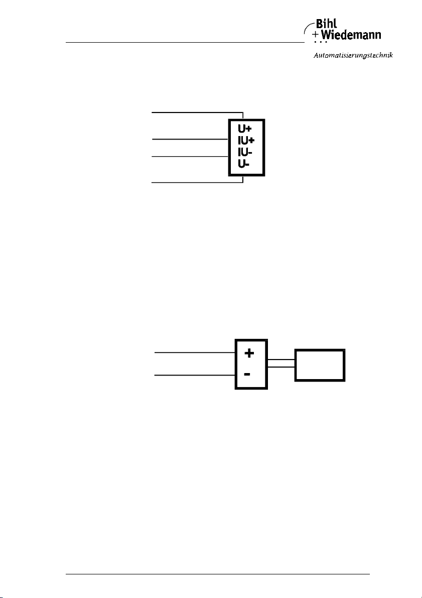
AS-Interface Analog Module Connections, Displays and Operating Keys
Connection of a 4-wire-sensor to the analog input module in IP20 with 2
channels:
Analog module 4-wire-sensor
24V ext.
Sig.+
Sig.-
GND
A 4-wire-sensor is attached to terminal 3 (24 V), 1 (I1 Sig.+) for current input respectively 9 (U1 Sig.*) for voltage input, 4 (0 V ext.) and 2 (I1 Sig.-) for current input respectively 10 (U1 Sig.-) of channel 1 (see figure above for details).
Corresponding channel 2 is attached via 7 (24 V) and 5 (I2 Sig.+) for current input
respectively 11 (U2 Sig.+) for voltage input as well as 8 (0 V ext.) and 6 (I2 Sig.-)
for current input repsectively 12 (U2 Sig.-) for voltage input.
Connection of a sensor with own power supply to the analog input module
in IP20 with 2 channels:
Analog module Sensor with own power supply
24V ext.
Sig.+
Sig.-
0V ext.
supply PELV
without earth
connection
A sensor with own supply is attached f or channel 1 to terminal 1 (I1 Sig.+) and 2
(I1 Sig.-) respectively for voltage input to terminals 9 (U1 Sig.+) and 10 (U1 Sig.-)
of channel 1.
Corresponding channel 2 is attached for current input via 5 (I2 Sig.+) and 6
(I2 Sig.-) respectively for voltage input via 11 (U2 Sig.+) and 12 (U2 Sig.-).
issue date 20.1.20 04
Subject to reas onable modifications due to technical advances Copyright Bihl+ Wiedemann, Printed in Germa ny
Bihl+W iedemann GmbH · D -68199 Mannh eim · Phone +49-62 1-339960 · Fax +49 -621-3392239 · I nternet http://w ww.bihl-wiedeman n.de
41
Page 42
AS-Interface Analog Module Connections, Displays and Operating Keys
4.5.2.2 Pin Configuration of the Analog Output Module (0 … 20 mA) in IP20 with 2 Channels
Connection of an actuator without separate power supply to the analog output module in IP20 with 2 channels:
Analog module Actuator without separate 24 V supply
24V ext.
Sig.+
Sig.-
0V ext.
A 2-wire-actuator is attached to terminal 1 (I1 Sig.+) and 2 (I1 Sig.-) of channel 1.
Corresponding channel 2 is attached via 5 (I2 Sig.+) and 6 (I2 Sig.-).
Connection of an actuator with own power supplyto the analog output module in IP20 with 2 channels:
Analog module Actuator with own power supply
24V ext.
Sig.+
Sig.-
0V ext.
supply PELV
without earth
connection
An actuator with own power supply (e. g. an ampmeter) is attached to terminal 1
(I1 Sig.+) and 2 (I1 Sig.-) of channel 1.
Corresponding channel 2 is attached via 5 (I2 Sig.+) and 6 (I2 Sig.-).
Subject to reasonable modifications due to technical advances Copyright Bihl+Wiedemann, Printed in Germany
42
Bihl+W iedemann GmbH · D -68199 Mannh eim · Phone +49-62 1-339960 · Fax +49 -621-3392239 · I nternet http://w ww.bihl-wiedemann .de
issue date 20.1.20 04
Page 43
AS-Interface Analog Module Connections, Displays and Operating Keys
Connection of an actuator with separate 24 V power supplyto the analog output module in IP20 with 2 channels:
Analog module Actuator with separate 24 V power supply
24V ext.
Sig.+
Sig.-
0V ext.
The separate 24 V are attached to terminal 3 (24 V) and 4 (0 V ext.), the analog
signal to terminal 1 (I1 Sig.+) and 2 (I1 Sig.-) of channel 1.
Corresponding channel 2 is attached via terminals 7 (24 V) and 8 (0 V ext.) as well
as 5 (I2 Sig.+) and 6 (I2 Sig.-).
issue date 20.1.20 04
Subject to reas onable modifications due to technical advances Copyright Bihl+ Wiedemann, Printed in Germa ny
Bihl+W iedemann GmbH · D -68199 Mannh eim · Phone +49-62 1-339960 · Fax +49 -621-3392239 · I nternet http://w ww.bihl-wiedeman n.de
43
Page 44
AS-Interface Analog Module Connections, Displays and Operating Keys
4.5.2.3 Pin Configuration of the Analog Output Module (0 … 10 V) in IP20 with 2 Channels
Connection of an actuator with own power supply to the analog output module in IP20 with 2 channels:
Analog module Actuator with own power supply
24V ext.
Sig.+
Sig.-
supply PELV
without earth
connection
0V ext.
An actuator with own power supply (e. g. a voltmeter) is attached to terminals 9
(U2 Sig.+) and 4 (0 V ext.) of channel 1, as well as terminals 11 (U2 Sig.+) and 8
(0 V ext.) of channel 2.
Connection of an actuator with separate 24 V power supply to the analog
output module in IP20 with 2 channels:
Analog module Actuator with separate 24 V power supply
24V ext.
Sig.+
Sig.-
0V ext.
The separate 24 V are attached to terminal 3 (24 V) and 4 (0 V ext.), the analog
signal to terminal 9 (U2 Sig.+) and 4 (0 V ext.) of channel 1.
Corresponding channel 2 is attached via terminals 7 (24 V) and 8 (0 V ext.) as well
as 11 (U2 Sig.+) and 8 (0 V ext.).
Subject to reasonable modifications due to technical advances Copyright Bihl+Wiedemann, Printed in Germany
44
Bihl+W iedemann GmbH · D -68199 Mannh eim · Phone +49-62 1-339960 · Fax +49 -621-3392239 · I nternet http://w ww.bihl-wiedemann .de
issue date 20.1.20 04
Page 45
AS-Interface Analog Module Connections, Displays and Operating Keys
4.5.3 Analog Modules in IP20 with 4 Channels
4.5.3.1 Pin Configuration of the Analog Input Modules in IP20 with 4 Channels
Connection of a 2-wire-sensor to the analog input module in IP20 with 4
channels:
Analog module 2-wire-sensor
24V
Sig.+
Sig.
-
0V ext.
A 2-wire-sensor is attached to terminal 1 (24 V) and 2 (I1 Sig.+) of channel 1. The
terminals 3 (0 V ext.) and 4 (I1 Sig.-) have to be connected to each other by using
a bridge.
Corresponding channel 2 is atteched via terminal 5 (24 V) and 6 (I2 Sig.+) as well
as 7 (0 V ext. and 8 (I2 Sig.-).
Corresponding channel 3 is atteched via terminal 9 (24 V) and 10 (I3 Sig.+) as well
as 11 (0 V ext. and 12 (I3 Sig.-).
Corresponding channel 4 is atteched via ter minal 16 (24 V) and 15 (I4 Sig.+) as
well as 17 (0 V ext. and 13 (I4 Sig.-).
Connection of a 3-wire-sensor to the analog input module in IP20 with 4
channels:
Analog module 3-wire-sensor
24V
Sig.+
Sig. -
A 3-wire-sensor is attached to terminal 1 (24 V) and 2 (I1 Sig.+) of channel 1. The
terminals 3 (0 V ext.) and 4 (I1 Sig.-) have to be connected to each other by using
a bridge.
Corresponding channel 2 is atteched via terminal 5 (24 V) and 6 (I2 Sig.+) as well
as 7 (0 V ext. and 8 (I2 Sig.-).
issue date 20.1.20 04
Subject to reas onable modifications due to technical advances Copyright Bihl+ Wiedemann, Printed in Germa ny
Bihl+W iedemann GmbH · D -68199 Mannh eim · Phone +49-62 1-339960 · Fax +49 -621-3392239 · I nternet http://w ww.bihl-wiedeman n.de
45
Page 46
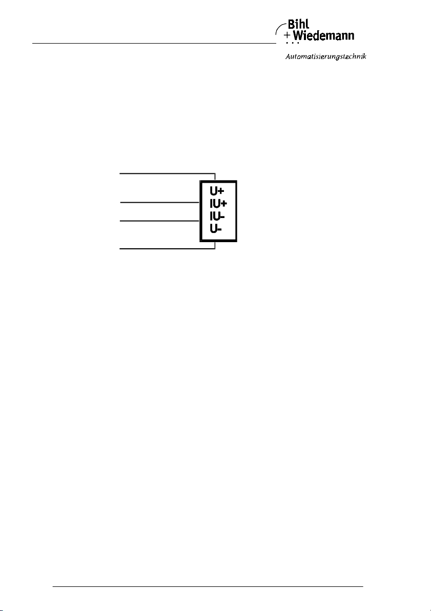
AS-Interface Analog Module Connections, Displays and Operating Keys
Corresponding channel 3 is atteched via terminal 9 (24 V) and 10 (I3 Sig.+) as well
as 11 (0 V ext. and 12 (I3 Sig.-).
Corresponding channel 4 is atteched via terminal 16 (24 V) and 15 (I4 Sig.+) as
well as 17 (0 V ext. and 13 (I4 Sig.-).
Connection of a 4-wire-sensor to the analog input module in IP20 with 4
channels:
Analog module 4-wire-sensor
24V
Sig.+
Sig.
-
A 4-wire-sensor is attached as shown to terminal 1 (24 V), 2 (I1 Sig.+), 3 (0 V ext.)
and 4 (I1 Sig.-) of channel 1.
Corresponding channel 2 is atteched via terminal 5 (24 V) and 6 (I2 Sig.+) as well
as 7 (0 V ext. and 8 (I2 Sig.-).
Corresponding channel 3 is atteched via terminal 9 (24 V) and 10 (I3 Sig.+) as well
as 11 (0 V ext. and 12 (I3 Sig.-).
Corresponding channel 4 is atteched via terminal 16 (24 V) and 15 (I4 Sig.+) as
well as 17 (0 V ext. and 13 (I4 Sig.-).
By the analog input modules with 4 current inputs in the delivery state are provided
between the terminal 1 and 2 a resitor and between the terminals 5 + 6, 9 + 10 and
16 + 15 each a bridge, that by the first commissioning of the module with only one
connected sensor (at input channel 1) no error message is displayed from the
module (for the input channels 2 - 4)
For use of a sensor at channel 2, 3 or 4 the resitor and if necessary the bridgeshave to be removed.
Subject to reasonable modifications due to technical advances Copyright Bihl+Wiedemann, Printed in Germany
46
Bihl+W iedemann GmbH · D -68199 Mannh eim · Phone +49-62 1-339960 · Fax +49 -621-3392239 · I nternet http://w ww.bihl-wiedemann .de
issue date 20.1.20 04
Page 47
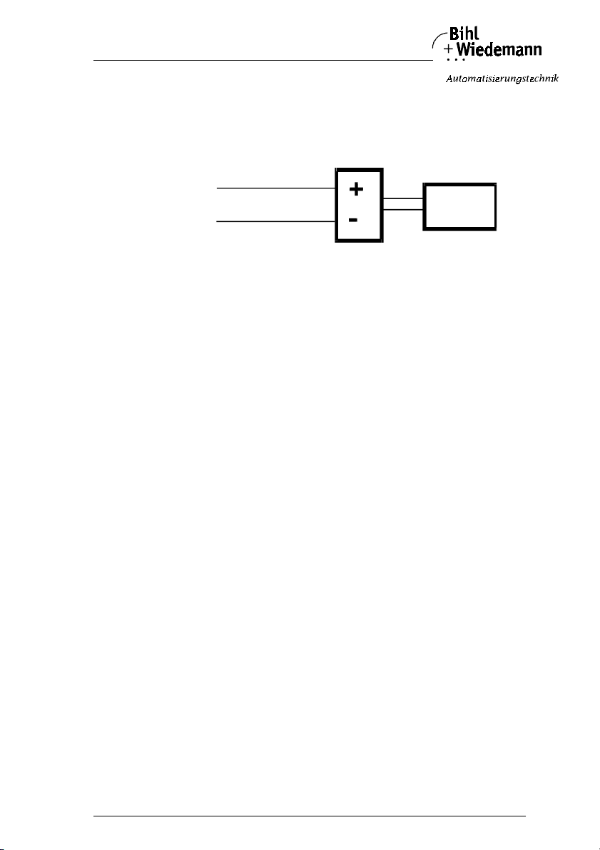
AS-Interface Analog Module Connections, Displays and Operating Keys
Connection of a sensor with own power supply to the analog input module
in IP20 with 4 channels:
Analog module Sensor with own power supply
24V
Sig.+
Sig.
0V ext.
-
A sensor with own power supply is atteched via terminals 2 (I1 Sig.+) and 4
(I1 Sig.-) of channel 1.
Corresponding channel 2 is atteched via ter minal 6 (I2 Sig.+) as well as 8
(I2 Sig.-).
Corresponding channel 3 is atteched via ter minal 0 (I3 Sig.+) as well as 12
(I3 Sig.-).
Corresponding channel 4 is atteched via terminal 15 (I4 Sig.+) as well as 13
(I4 Sig.-).
supply PELV
without e art h
connection
issue date 20.1.20 04
Subject to reas onable modifications due to technical advances Copyright Bihl+ Wiedemann, Printed in Germa ny
Bihl+W iedemann GmbH · D -68199 Mannh eim · Phone +49-62 1-339960 · Fax +49 -621-3392239 · I nternet http://w ww.bihl-wiedeman n.de
47
Page 48
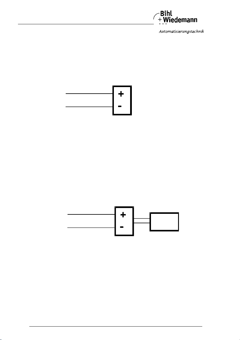
AS-Interface Analog Module Connections, Displays and Operating Keys
4.5.3.2 Pin Configuration of the Analog Output Module (0 … 20 mA) in IP20 with 4 Channels
Connection of an actuator without separate power supply to the analog output module in IP20 with 4 channels:
Analog module Actuator without seperate 24 V power supply
24V
Sig.+
Sig.
-
0V ext.
A 2-wire-actuator is attached to terminal 2 (O1 Sig.+) and 4 (O1 Sig.-) of
channel 1.
Corresponding channel 2 is attached via 6 (O2 Sig.+) and 8 (O2 Sig.-).
Corresponding channel 3 is attached via 10 (O3 Sig.+) and 12 (O3 Sig.-).
Corresponding channel 4 is attached via 15 (O4 Sig.+) and 13 (O4 Sig.-).
Connection of an actuator with own power supply to the analog output module in IP20 with 4 channels:
Analog module Actuator with own power supply
24V
Sig.+
Sig.
0V ext.
-
supply PE LV
without earth
connection
An actuator with own power supply (e. g. a voltmeter) is attached to terminals 2
(O1 Sig.+) and 4 (O1 Sig.-) of channel 1.
Corresponding channel 2 is attached via 6 (O2 Sig.+) and 8 (O2 Sig.-).
Corresponding channel 3 is attached via 10 (O3 Sig.+) and 12 (O3 Sig.-).
Corresponding channel 4 is attached via 15 (O4 Sig.+) and 13 (O4 Sig.-).
Subject to reasonable modifications due to technical advances Copyright Bihl+Wiedemann, Printed in Germany
48
Bihl+W iedemann GmbH · D -68199 Mannh eim · Phone +49-62 1-339960 · Fax +49 -621-3392239 · I nternet http://w ww.bihl-wiedemann .de
issue date 20.1.20 04
Page 49
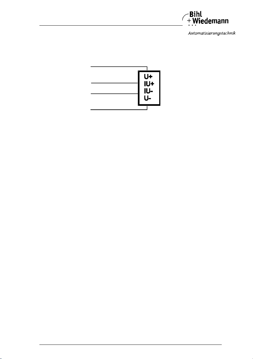
AS-Interface Analog Module Connections, Displays and Operating Keys
Connection of an actuator with separate 24 V power supply to the analog
output module in IP20 with 4 channels:
Analog module Actuator with sperate 24 V power supply
24V
Sig.+
Sig.
-
The separate 24 V are attached to terminal 1 (24 V) and 3 (0 V ext.), the analog
signal to terminal 2 (O1 Sig.+) and 4 (O1 Sig.-) of channel 1.
Corresponding channel 2 is attached via terminals 5 (24 V) and 7 (0 V ext.) as well
as 6 (O2 Sig.+) and 8 (O2 Sig.-).
Corresponding channel 3 is attached via terminals 9 (24 V) and 11 (0 V ext.) as
well as 10 (O3 Sig.+) and 12 (O3 Sig.-).
Corresponding channel 4 is attached via terminals 16 (24 V) and 14 (0 V ext.) as
well as 15 (O4 Sig.+) and 13 (O4 Sig.-).
issue date 20.1.20 04
Subject to reas onable modifications due to technical advances Copyright Bihl+ Wiedemann, Printed in Germa ny
Bihl+W iedemann GmbH · D -68199 Mannh eim · Phone +49-62 1-339960 · Fax +49 -621-3392239 · I nternet http://w ww.bihl-wiedeman n.de
49
Page 50
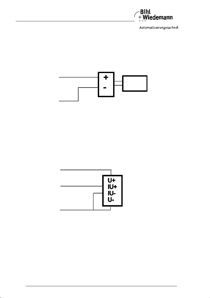
AS-Interface Analog Module Connections, Displays and Operating Keys
4.5.3.3 Pin Configuration of the Analog Output Module (0 … 10 V) in IP20 with 4 Channels
Connection of an actuator with own power supply to the analog output module in IP20 with 4 channels:
Analog module Actuator with own power supply
24V
Sig.+
Sig.
0V ext.
-
supply P ELV
without earth
connection
An actuator with own power supply (e. g. a voltmeter) is attached to terminals 2
(O1 Sig.+) and 3 (0 V ext.) of channel 1.
Corresponding channel 2 is attached via 6 (O2 Sig.+) and 7 (0 V ext).
Corresponding channel 3 is attached via 10 (O3 Sig.+) and 11 (0 V ext).
Corresponding channel 4 is attached via 15 (O4 Sig.+) and 14 (0 V ext).
Connection of an actuator without separate power supply to the analog output module in IP20 with 4 channels:
Analog module Actuator w ith sperate 24 V power supply
24V
Sig.+
Sig. -
The separate 24 V are attached to terminal 1 (24 V) and 3 (0 V ext.), the analog
signal to terminal 11 (O2 Sig.+) and 8 (0 V ext.) of channel 1.
Corresponding channel 2 is attached via terminals 5 (24 V) and 7 (0 V ext.) as well
as 6 (O2 Sig.+) and 7 (0 V ext.).
Corresponding channel 3 is attached via terminals 9 (24 V) and 11 (0 V ext.) as
well as 10 (O3 Sig.+) and 11 (0 V ext.).
Corresponding channel 4 is attached via terminals 16 (24 V) and 14 (0 V ext.) as
well as 15 (O4 Sig.+) and 14 (0 V ext.).
Subject to reasonable modifications due to technical advances Copyright Bihl+Wiedemann, Printed in Germany
50
Bihl+W iedemann GmbH · D -68199 Mannh eim · Phone +49-62 1-339960 · Fax +49 -621-3392239 · I nternet http://w ww.bihl-wiedemann .de
issue date 20.1.20 04
Page 51
AS-Interface Analog Module Connections, Displays and Operating Keys
4.5.3.4 Pin Configuration of the AS-Interface Pt100 Module in IP20 with 4 Channels
Connection of a 2-wire-Pt100 element to the AS-Interface Pt100 module in
IP20 with 4 channels:
Analog module Pt100 element
CH +
Ch Sense -
CH -
Channel 1 applies to terminals 6 and 7, channel 2 applies to terminals 10 and 11,
channel 3 applies to terminals 15 and 14 and channel 4 applies to terminals 19 and
18.
Terminals 6, 10, 15 and 19 (Ch. +) are interconnected inside the module.
Connection of a 4-wire-Pt100 element to the AS-Interface Pt100 module in
IP20 with 4 channels:
Analog module Pt100 element
CHS +
CH +
Ch Sense
CH
CHS
-
-
-
Channel 1 applies to terminals 6 - 5, 8 - 7, channel 2 applies to terminals 10 - 9,
12 - 11, channel 3 applies to terminals 15 - 16, 13 - 14 and channel 4 applies to
terminals 19 - 20, 17 - 18.
Terminals 6, 10, 15 and 19 (Ch. +) are interconnected inside the module.
4-wire-Pt100 sensors yield better results than 2-wire-sensors.
Switching between 4- and 2-wire-sensors takes place via AS-Interface parameter
bit 3.
The Pt100 moduls are deliverd with resistors between terminal 10 and 11, 15 and
14 as well as 19 and 18. With that it is prevented that a fault message is notified
by the module when it is brought into service and only one sensor is attached.
issue date 20.1.20 04
Subject to reas onable modifications due to technical advances Copyright Bihl+ Wiedemann, Printed in Germa ny
Bihl+W iedemann GmbH · D -68199 Mannh eim · Phone +49-62 1-339960 · Fax +49 -621-3392239 · I nternet http://w ww.bihl-wiedeman n.de
51
Page 52
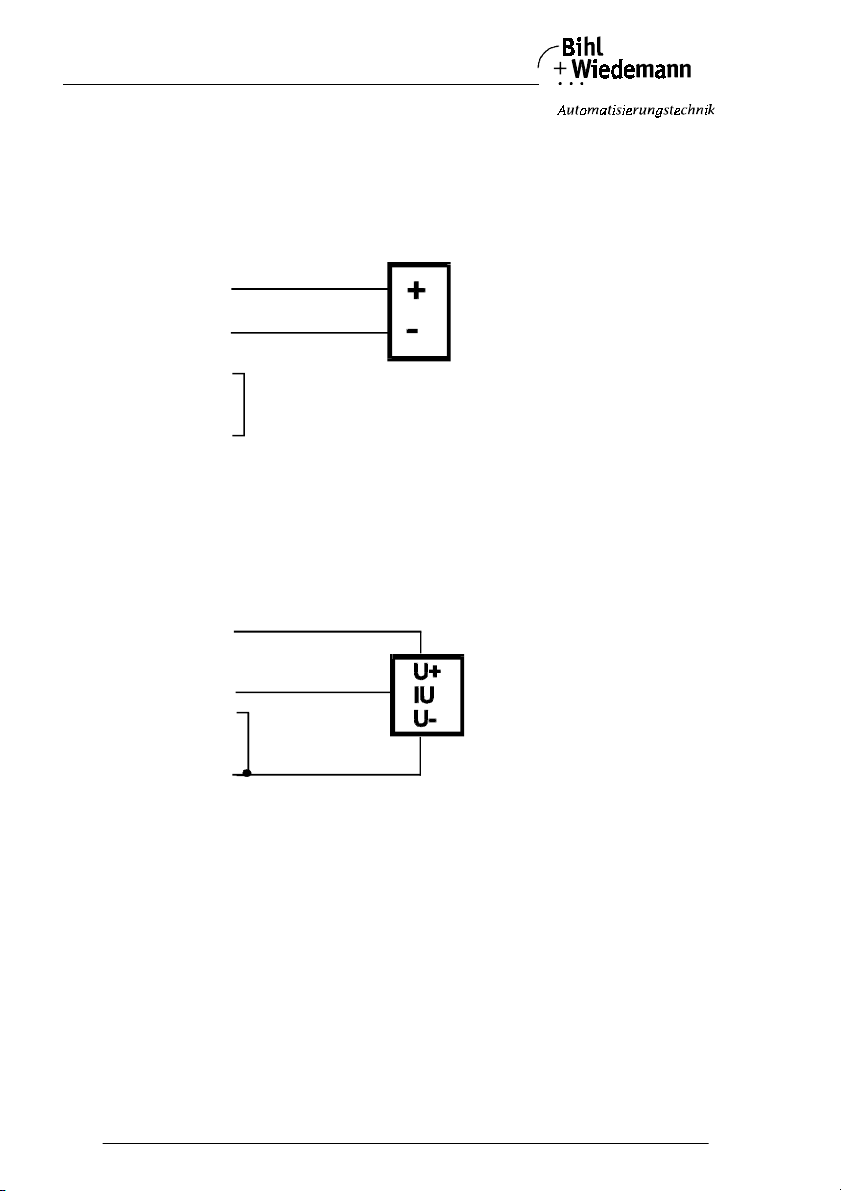
AS-Interface Analog Module Connections, Displays and Operating Keys
4.5.4 Analog Modules with M12 Connection in IP65 with 4 Channels
4.5.4.1 Pin Configuration of the Analog Input Modules in IP65 with 4 Channels
Connection of a 2-wire-sensor to the analog input module in IP65 with 4
channels:
Analog module 2-wire-sensor
24V
Sig.+
Sig.
-
0V ext.
A 2-wire-sensor is attached to the pins 1 (24 V) and 2 (Sig.+) of channel 1. The
pins 3 (0 V ext.) and 4 (Sig.-) have to be connected to each other by using a bridge.
Corresponding for channel 2, 3, 4.
Connection of a 3-wire-sensor to the analog input module in IP65 with 4
channels:
Analog module 3-wire-sensor
24V
Sig.+
Sig. -
A 3-wire-sensor is attached to the pins 1 (24 V) and 2 (Sig.+) of channel 1. The
terminals 3 (0 V ext.) and 4 (Sig.-) have to be connected to each other by using a
bridge.
Corresponding for channel 2, 3, 4.
Subject to reasonable modifications due to technical advances Copyright Bihl+Wiedemann, Printed in Germany
52
Bihl+W iedemann GmbH · D -68199 Mannh eim · Phone +49-62 1-339960 · Fax +49 -621-3392239 · I nternet http://w ww.bihl-wiedemann .de
issue date 20.1.20 04
Page 53
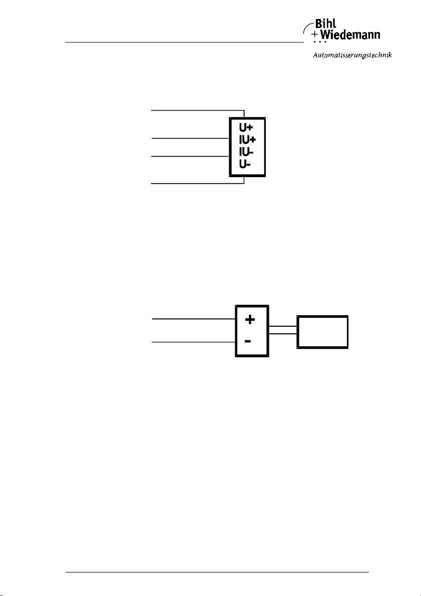
AS-Interface Analog Module Connections, Displays and Operating Keys
Connection of a 4-wire-sensor to the analog input module in IP65 with 4
channels:
Analog module 4-wire-sensor
24V
Sig.+
Sig.
-
A 4-wire-sensor is attached as shown to the pins 1 (24 V), 2 (Sig.+), 3 (0 V ext.)
and 4 (Sig.-) of channel 1.
Corresponding for channel 2, 3, 4.
Connection of a sensor with own power supply to the analog input module
in IP65 with 4 channels:
Analog module Sensor with own power supply
24V
Sig.+
Sig.
-
0V ext.
supply PELV
without e art h
connection
A sensor with own power supply is atteched via the pins 2 (Sig.+) and 4 (Sig.-) of
channel 1.
Corresponding for channel 2, 3, 4.
issue date 20.1.20 04
Subject to reas onable modifications due to technical advances Copyright Bihl+ Wiedemann, Printed in Germa ny
Bihl+W iedemann GmbH · D -68199 Mannh eim · Phone +49-62 1-339960 · Fax +49 -621-3392239 · I nternet http://w ww.bihl-wiedeman n.de
53
Page 54
AS-Interface Analog Module Connections, Displays and Operating Keys
4.5.4.2 Pin Configuration of the Analog Output Module (0 … 20 mA) in IP65 with 4 Channels
Connection of an actuator without separate power supply to the analog output module in IP65 with 4 channels:
Analog module Actuator without seperate 24 V power supply
Sig.+
Sig.
-
A 2-wire-actuator is attached to the pins 2 (Sig.+) and 4 (Sig.-) of channel 1.
Corresponding for channel 2, 3, 4.
Connection of an actuator with own power supply to the analog output module in IP65 with 4 channels:
Analog module Actuator with own power supply
Sig.+
Sig.
supply PELV
without earth
-
connection
An actuator with own power supply (e. g. a voltmeter) is attached to the pins 2
(Sig.+) and 4 (Sig.-) of channel 1.
Corresponding for channel 2, 3, 4.
Subject to reasonable modifications due to technical advances Copyright Bihl+Wiedemann, Printed in Germany
54
Bihl+W iedemann GmbH · D -68199 Mannh eim · Phone +49-62 1-339960 · Fax +49 -621-3392239 · I nternet http://w ww.bihl-wiedemann .de
issue date 20.1.20 04
Page 55
AS-Interface Analog Module Connections, Displays and Operating Keys
4.5.4.3 Pin Configuration of the Analog Output Module (0 … 10 V) in IP65 with
4 Channels
Connection of an actuator with own power supply to the analog output module in I P65 with 4 channels:
Analog module Actuator with own power supply
24V
Sig.+
Sig.
0V ext.
-
supply P ELV
without earth
connection
An actuator with own power supply (e. g. a voltmeter) is attached to the pins 2
(Sig.+) and 4 (Sig.-) of channel 1.
Corresponding for channel 2, 3, 4.
4-wire-Pt100 sensors yield better results than 2-wire-sensors.
Switching between 4- and 2-wire-sensors takes place via AS-Interface parameter
bit 3.
issue date 20.1.20 04
Subject to reas onable modifications due to technical advances Copyright Bihl+ Wiedemann, Printed in Germa ny
Bihl+W iedemann GmbH · D -68199 Mannh eim · Phone +49-62 1-339960 · Fax +49 -621-3392239 · I nternet http://w ww.bihl-wiedeman n.de
55
Page 56
AS-Interface Analog Module Connections, Displays and Operating Keys
4.5.4.4 Pin Configuration of the AS-Interface Pt100 Module in IP65 with 4 Channels
Connection of a 2-wire-Pt100 element to the AS-Interface Pt100 module in
IP65 with 4 channels:
Analog module Pt100 element
CH +
Ch Sense -
CH -
Channel 1 applies to the pins 1 and 3
Corresponding for channel 2, 3, 4.
Connection of a 4-wire-Pt100 element to the AS-Interface Pt100 module in
IP65 with 4 channels:
Analog module Pt100 element
CHS +
CH +
Ch Sense
CH
CHS
-
-
-
Channel 1 applies to the pins 1 - 2, 3 - 4.
The pins (CH+) of the four M12 are connected together within the module.
Corresponding for channel 2, 3, 4.
Subject to reasonable modifications due to technical advances Copyright Bihl+Wiedemann, Printed in Germany
56
Bihl+W iedemann GmbH · D -68199 Mannh eim · Phone +49-62 1-339960 · Fax +49 -621-3392239 · I nternet http://w ww.bihl-wiedemann .de
issue date 20.1.20 04
Page 57

AS-Interface Analog Module Operating the Modules
5 Operating the Modules
5.1 Addressing the Modules
The addressing of the AS-Interface slaves takes place by the aid of a hand addressing device or an AS-Interface master. When employing the hand addressing device the AS-Interface slave is simply stuck on the device and addressed. It is
possible to use addresses between 1 and 31. In the condition of delivery the
address is 0.
5.2 Operation of Analog Input Modules in IP20 and IP65
This chapter gives all necessary information which is needed to operate the AS-Interface analog input modules with either 2 resp. 4 inputs 4 - 20 mA or 2 inputs
0-10V.
Presupposition: The AS-Interface analog module supports AS-Interface analog
profile 7.3. Via AS-Interf ace two 16 bit values per module are transmitted to the
AS-Interface master. In order to operate the module, it is necessary to use an
AS-Interface master which supports analog profile 7.3.
5.2.1 Slave Profile in IP20 und IP65
Configuration of the analog input in IP20 and IP65 modules is as follows:
Analog input modules with 2 channels:
•I/0- Code:7
• ID-Code: 3
• ID2-Code: D
Analog input modules with 4 channels:
•I/0- Code:7
• ID-Code: 3
• ID2-Code: E
5.2.2 Parameterization of the Analog Input Modules in IP20 and IP65
The adjustment of differing operation ranges is known as parameterization. It is
done via the AS-Interface master by executing the command "write AS-Interface
parameter" for example in the AS-Interface Control Tools in the window "slave
configuration". Under "data and parameters" the AS-Interface parameter bits can
be set or deleted.
By the analg modules in Protection category IP65 with 4 channels the AS-Interface
slaves can be programmed by an infrared interface.
Parameter settings of AS-Interface analog input modules can be adjusted as follows:
hex
hex
hex
hex
hex
hex
issue date 20.1.20 04
Subject to reas onable modifications due to technical advances Copyright Bihl+ Wiedemann, Printed in Germa ny
Bihl+W iedemann GmbH · D -68199 Mannh eim · Phone +49-62 1-339960 · Fax +49 -621-3392239 · I nternet http://w ww.bihl-wiedeman n.de
57
Page 58
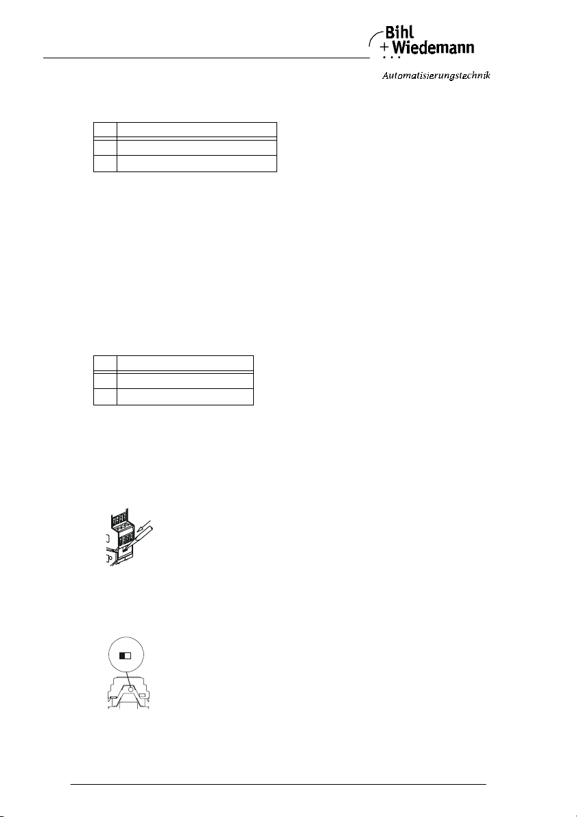
AS-Interface Analog Module Operating the Modules
5.2.2.1 Analog Module in IP20, 2 Channels and in IP65
AS-Interface parameter bit 0: Filter for mains frequency:
P0 filter in the A/D converter for
1 50 Hz (default)
060 Hz
The 50 Hz filter is valid in the whole of Europe.
AS-Interface parameter bit 1: Configuration of channel 2
By means of AS-Interface parameter bit 1 it is possible to adjust whether measuring channel 2 of the analog input module is active or not. Deactivating channel 2
shortens the conversion and transmission time and influences LED and peripheral
fault messages. LED displays and peripheral fault messages are not affected by
this channel anymore.
By deactivating channel 2 conversion and transmission time in the AS-Interface
slave can be intensely reduced (for additional information see chapter 5.2.4 respectively chapter 5.3.4).
P1 channel 2
1 configured (active)
0 not configured (not active)
Additionally it is possible by the analog input module in IP20, that the 2. channel
ist switched off with a switch inside the device.
Therefore the case of the module has to be opened as follows and the switch to
be adjusted:
1. Unlocking of the module´s top
On both sides of the module force the unlock buttons with help of
a screw driver
2. Openning the module
Pull out the top until stop
3. Adjusting the supply.
ON: Channal 2 on
ON OFF
Subject to reasonable modifications due to technical advances Copyright Bihl+Wiedemann, Printed in Germany
58
Bihl+W iedemann GmbH · D -68199 Mannh eim · Phone +49-62 1-339960 · Fax +49 -621-3392239 · I nternet http://w ww.bihl-wiedemann .de
OFF: Channal 2 off
issue date 20.1.20 04
Page 59
AS-Interface Analog Module Operating the Modules
The switch may be actuated by power-off only.
P1 switch position channel 2
1ONein
1OFFaus
0ONaus
0OFFaus
AS-Interface parameter bit 2: Display of a peripheral fault
By means of this bit, it is possible to adjust whether an adjacent peripheral fault is
notified by the flashing "FAULT"-LED of the module and the peripheral fault is
transmitted to the AS-Interface master.
P2 peripheral fault is
1 notified
0 not notified
5.2.2.2 Analog Modules in IP20 and IP65 with M12 Connection, 4 Channels
AS-Interface parameter bit 0: Filter for mains frequency (only input modules
in IP20):
P0 Filter im A/D-Wandler für
150Hz (default)
060Hz
The 50 Hz filter is valid in the whole of Europe.
Only current analog input modules in IP65:
With the help of the parameter bit 0 the bridge between pin 3 and pin 4 of the M12
socket is switched.
P0 Bridge between pin 3 and pin 4 of the M12 socket
1active
0 not active
issue date 20.1.20 04
Subject to reas onable modifications due to technical advances Copyright Bihl+ Wiedemann, Printed in Germa ny
Bihl+W iedemann GmbH · D -68199 Mannh eim · Phone +49-62 1-339960 · Fax +49 -621-3392239 · I nternet http://w ww.bihl-wiedeman n.de
59
Page 60
AS-Interface Analog Module Operating the Modules
AS-Interface parameter bits 1 and 2: Switching on/off of channels 2 - 4
With the help of these parameter bits the channels 2 - 4 can be switched on or off
each.
The channel 1 is switched on ever und can not be switched off.
analog i nput is
P1P21234
0 0 on off off off
0 1 on on off off
1 0 on on on off
1 1 on on on on
AS-Interface parameter bit 3: Display of a peripheral fault
By means of this bit, it is possible to adjust whether an adjacent peripheral fault is
notified by the flashing "FAULT"-LED of the module and the peripheral fault is
transmitted to the AS-Interface master.
P3 peripheral fault is
1notified
0 not notified
5.2.3 Measuring Range of Analog Input Modules
Analog input module 2/4 inputs, 4 - 20 mA:
Range 4 … 20 mA Units dec. Units hex. Analog LED Region
>23 mA 32767 7FFF flashing Overflow
23 mA 23000 59D8
… … … on Overrange
20,001 mA 20001 4E21
20 mA 20000 4E20
19,999 mA 19999 4E1F
… … … on Nominal range
4,001 mA 4001 0FA1
4 mA 4000 0FA0
3,999 mA 3999 0F9F
… … … on Underrange
1 mA 1000 03E8
<1 mA 32767 7FFF off Wire break
Subject to reasonable modifications due to technical advances Copyright Bihl+Wiedemann, Printed in Germany
60
Bihl+W iedemann GmbH · D -68199 Mannh eim · Phone +49-62 1-339960 · Fax +49 -621-3392239 · I nternet http://w ww.bihl-wiedemann .de
issue date 20.1.20 04
Page 61
AS-Interface Analog Module Operating the Modules
When switching channel 2 from active to inactive condition its last value is shown.
Input resistor: 50 Ohm
Max. input current: 40 mA
Wire break detection: yes
Analog input module 2/4 inputs, 0 - 10 V:
Range 0 … 10 V Units dec. Units hex. Analog LED Region
> 11,5 V 32767 7FFF flashing Overflow
11,5 V 11500 2CEC
… … … on Overrange
10,001 V 10001 2711
10 V 10000 2710
9,999 V 9999 270F
… … … on Nominal range
1 mV 0001 0001
0V 0000 0000
< 0V 0000 0000 on Underflow
When switching a channel from active condition to inactive condition its last value
is shown.
Max. voltage: 50 V
Input resistance: 100 kOhm
Wire break detection: yes
5.2.4 Transmission Time of Analog Parameters
The transmission time of analog parameters depends on the one hand on the conversion time of analog signals to digital signals in the AS-Interface module, on the
other hand on the transmission time via the AS-Interface.
5.2.4.1 Transmission Time of Analog Parameters for 2 Channels
The conversion time of 2 analog input signals into digital signals amounts to
120 ms. Wh en channel 2 is inactiv e, the conversion time of one channel i s reduced
to only 20 ms.
The transmission time of 2 16 bit parameters via the AS-Interface amounts - in
worst case - to 7 AS-Interface cycles per parameter. With one cycle period being
5 ms per AS-Interface cycle this sums up to a transmission time of 2 * 7 *
5 ms = 70 ms via AS-Interface.
When channel 2 is inactive, the transmission time via AS-Interface for just one
channel amounts to 7 AS-Interface cycles. With one cycle period being 5 ms per
AS-Interface cycle this sums up to a transmission time of 1 * 7 * 5 ms = 35 ms via
AS-Interface.
The transmission time for tr ansmission of 2 analog parameters totals - in worst
case - to 120 ms + 70 ms = 190 ms. When channel 2 is disconnected it can be reduced to a minimal total of 20 ms + 35 ms = 55 ms.
issue date 20.1.20 04
Subject to reas onable modifications due to technical advances Copyright Bihl+ Wiedemann, Printed in Germa ny
Bihl+W iedemann GmbH · D -68199 Mannh eim · Phone +49-62 1-339960 · Fax +49 -621-3392239 · I nternet http://w ww.bihl-wiedeman n.de
61
Page 62
AS-Interface Analog Module Operating the Modules
5.2.4.2 Transmission Time of Analog Parameters for 3 Channels
The conversion time of 3 analog input signals into digital signals amounts to
180 ms.
The transmission time of 3 16 bit parameters via the AS-Interface amounts - in
worst case - to 7 AS-Interface cycles per parameter. With one cycle period being
5 ms per AS-Interface cycle this sums up to a transmission time of 3 * 7 *
5 ms = 105 ms via AS-Interface.
The transmission time for transmission of 3 analog parameters totals - in worst
case - to 180 ms + 105 ms = 285 ms..
5.2.4.3 Transmission Time of Analog Parameters for 4 Channels
The conversion time of 4 analog input signals into digital signals amounts to
240 ms.
The transmission time of 4 16 bit parameters via the AS-Interface amounts - in
worst case - to 7 AS-Interface cycles per parameter. With one cycle period being
5 ms per AS-Interface cycle this sums up to a transmission time of 4 * 7 *
5 ms = 140 ms via AS-Interface.
The transmission time for transmission of 4 analog parameters totals - in worst
case - to 240 ms + 140 ms = 380 ms..
Subject to reasonable modifications due to technical advances Copyright Bihl+Wiedemann, Printed in Germany
62
Bihl+W iedemann GmbH · D -68199 Mannh eim · Phone +49-62 1-339960 · Fax +49 -621-3392239 · I nternet http://w ww.bihl-wiedemann .de
issue date 20.1.20 04
Page 63
AS-Interface Analog Module Operating the Modules
5.3 Operation of AS-Interface Analog Output Modules in IP20 and IP65
This chapter gives all necessary information which is needed to operate an AS-Interface analog output module with either 2/4 outputs 4 - 20 mA or 2/4 outputs
0-10V.
Presupposition: The AS-Interface analog modules support AS-Interface analog
profile 7.3. Via AS-Interf ace two resp. four 16 bit values per module are transmitted to the AS-Interface master. In order to operate the module, it is necessary to
use an AS-Interface master which supports analog profile 7.3.
5.3.1 Slave Profile
Configuration of analog output modules is as follows:
Analog output modules with 2 channels:
•I/0- Code:7
• ID-Code: 3
• ID2-Code:5
hex
hex
hex
Analog output modules with 4 channels:
•I/0- Code:7
• ID-Code: 3
• ID2-Code:6
hex
hex
hex
5.3.2 Parameterization of Analog Output Modules in IP20 and IP65
The adjustment of differing operation ranges is known as parameterization. It is
done via the AS-Interface master by executing the command "write AS-Interface
parameter".
5.3.2.1 Analog Output Module in IP65
Parameter settings of AS-Interface analog output modules can be adjusted as follows:
AS-Interface parameter bit 0:
Not used
AS-Interface parameter bit 1:
Not used
AS-Interface parameter bit 2: Display of a peripheral fault
By means of this bit, it is possible to adjust whether an adjacent peripheral fault is
notified by the flashing "FAULT"-LED of the module and the peripheral fault is
transmitted to the AS-Interface master.
P2 peripheral fault is
1 notified
0 not notified
issue date 20.1.20 04
Subject to reas onable modifications due to technical advances Copyright Bihl+ Wiedemann, Printed in Germa ny
Bihl+W iedemann GmbH · D -68199 Mannh eim · Phone +49-62 1-339960 · Fax +49 -621-3392239 · I nternet http://w ww.bihl-wiedeman n.de
63
Page 64
AS-Interface Analog Module Operating the Modules
AS-Interface parameter bit 3:
Not used
5.3.2.2 Analog Output Modules in IP 20, 2 Channels
Parameter settings of AS-Interface analog output modules in IP20 with 2 channels
can be adjusted as follows:
AS-Interface parameter bit 0:
With the parameter bit 0 it can adjusted, if the AS-Interface analog output module
should detect the respective ouput mode automatically or the mode is adjustetd
stationary by the AS-Interface parameter bits P1 respectively P3.
P0 selection of the output mode
1 Automatic detection of the module
0 With the parameter bits P1, P3 the mode for channel 1 and 2 can be adju-
sted
AS-Interface parameter bits 1 and 3: Adjusting the mode for channel 1 and 2
If parameter bit P0 = 0, the mode for channel 1 and 2 can be adjusted stationary
with the help of parameter bits P1 and P3.
P1 channel 1 works as
1 current output
0 voltage output
P3 channel 2 works as
1 current output
0 voltage output
AS-Interface parameter bit 2: Display of a peripheral fault
By means of this bit, it is possible to adjust whether an adjacent peripheral fault is
notified by the flashing "FAULT"-LED of the module and the peripheral fault is
transmitted to the AS-Interface master.
P2 peripheral fault is
1notified
0 not notified
5.3.2.3 Analog Output Modules in IP20 and IP65 with M12 Connection, 4 Channelsl
Parameter settings of AS-Interface analog output modules in IP20 and IP65 with
M12 connection and 4 channels can be adjusted as follows:
AS-Interface parameter bit 0: Monitoring of the Profile 7.3
By means of this bit, it is possible to adjust whether the data transmission according profile 7.2 is monitored, that means each channel is checked by interruption
Subject to reasonable modifications due to technical advances Copyright Bihl+Wiedemann, Printed in Germany
64
Bihl+W iedemann GmbH · D -68199 Mannh eim · Phone +49-62 1-339960 · Fax +49 -621-3392239 · I nternet http://w ww.bihl-wiedemann .de
issue date 20.1.20 04
Page 65
AS-Interface Analog Module Operating the Modules
of the transmission. After a watchdog time of 0,5 s the respective channel is released to 0 V respectively 0 mA.
P0 Profile 7.3 is
1 monitored
0 not monitored
AS-Interface parameter bit 1:
Not used
AS-Interface parameter bit 2: Display of a peripheral fault
By means of this bit, it is possible to adjust whether an adjacent peripheral fault is
notified by the flashing "FAULT"-LED of the module and the peripheral fault is
transmitted to the AS-Interface master.
P3 peripheral fault is
1 notified
0 not notified
AS-Interface parameter bit 3:
Not used
5.3.3 Measuring Range of Analog Output Modules
Analog output module 2/4 outputs, 0 - 20 mA:
Output value
0…20 mA
Units dec. Units hex. Analo g LED Region
23 mA >23000 >59D8 flashing Overflow
23 mA 23000 59D8
… … … on Overrange
20,001 mA 20001 4E21
20 mA 20000 4E20
19,999 mA 19999 4E1F
………on
µ
A 0001 0001
1
Nominal range
0 mA 0000 0000
0 mA <0000 < 0000 flashing Underrange
Shunt resistance: max. 600 Ohm
Short-circuit proof: yes
Wire break recognition:no
issue date 20.1.20 04
Subject to reas onable modifications due to technical advances Copyright Bihl+ Wiedemann, Printed in Germa ny
Bihl+W iedemann GmbH · D -68199 Mannh eim · Phone +49-62 1-339960 · Fax +49 -621-3392239 · I nternet http://w ww.bihl-wiedeman n.de
65
Page 66
AS-Interface Analog Module Operating the Modules
Analog output module 2/4 outputs, 0 - 10 V:
Output ra nge
0…10V
Units dec. Units hex. Analog LED Region
11,5 V >11500 >2CEC flashing Overflow
11,5 V 11500 2CEC
… … … on Overrange
10,001 V 10001 2711
10 V 10000 2710
9,999 V 9999 270F
………on
Nominal range
1 mV 0001 0001
0V 0000 0000
0V < 0000 < 0000 flashing Underrange
IP65 with 2 channels IP20 with 2 channels IP20 and IP65
Load resistence (min.): 3,3 kOhm 1,2 kOhm 1,2 kOhm
Short-circuit proof: yes yes yes
Short-circuit current: 4 mA 18 mA 18 mA
Wire break recognition: no no no
5.3.4 Transmission Time of Analog Parameters
The transmission time of analog parameters depends on the one hand on the conversion time of analog signals to digital signals in the AS-Interface module, on the
other hand on the transmission time via the AS-Interface.
The conversion time of 2 analog input signals into digital signals is < 1 ms.
5.3.4.1 Transmission Time of Analog Parameters for 2 Channels
The transmission time of 2 16 bit parameters via the AS-Interface amounts - in
worst case - to 7 AS-Interface cycles per parameter. With one cycle period being
5 ms per AS-Interface cycle this sums up to a transmission time of 2 * 7 * 5 ms =
70 ms via AS-Interface.
The transmission time for transmission of 2 analog parameters totals - in worst
case - to 1 ms + 70 ms = 71 ms.
5.3.4.2 Transmission Time of Analog Parameters for 4 Channels
The transmission time of 4 16 bit parameters via the AS-Interface amounts - in
worst case - to 7 AS-Interface cycles per parameter. With one cycle period being
5 ms per AS-Interface cycle this sums up to a transmission time of 4 * 7 * 5 ms =
140 ms via AS-Interface.
The transmission time for transmission of 4 analog parameters totals - in worst
case - to 1 ms + 140 ms = 141 ms.
with 4 channe ls
Subject to reasonable modifications due to technical advances Copyright Bihl+Wiedemann, Printed in Germany
66
Bihl+W iedemann GmbH · D -68199 Mannh eim · Phone +49-62 1-339960 · Fax +49 -621-3392239 · I nternet http://w ww.bihl-wiedemann .de
issue date 20.1.20 04
Page 67
AS-Interface Analog Module Operating the Modules
5.4 Operation of the Pt100 Modules in IP20 and IP65
This chapter gives all necessary information which is needed to operate the Pt100
modules.
Presupposition: The AS-Interface Pt100 module supports AS-Interface analog
profile 7.3. Via AS-Interface four 16 bit values are transmitted from the Pt100 module to the AS-Interface master. In order to operate the module, it is necessary to
use an AS-Interface master which supports analog profile 7.3.
It is necessary to attach at least one Pt100 sensor in order to start the A/D converter before switching on the slaves. Otherwise LED1, LED2, LED3, LED6 will blink
with a frequency of app. 5 Hz.
5.4.1 Slave Profile
Configuration of the Pt100 module is as follows:
•I/0- Code:7
• ID-Code: 3
• ID2-Code:E
hex
hex
hex
5.4.2 Parameterization of the AS-Interface Pt100 Modules
The adjustment of differing operation ranges is known as parameterization. It is
done via the AS-Interface master by executing the command "write AS-Interface
parameter".
Parameter settings of AS-Interface Pt100 blocks can be adjusted as follows:
AS-Interface parameter bit 0: Filter for mains frequency:
P0 filter in the A/D converter for
1 50 Hz (default)
0 60 Hz
The 50 Hz filter is valid in the whole of Europe.
AS-Interface parameter bits P1 and P2: Configuration of peripheral fault
messages of channels 1 to 4
By means of AS-Interface parameter bits P1 and P2 it is possible to adjust which
measuring channels of the module are active or not. Configuration only effects peripheral fault messages. Adjacent measuring parameters of all 4 channels are always transmitted via AS-Interface.
peripheral fault can be caused by channel
P1P21234
00yesnonono
0 1 yes yes no no
10yesyesyesno
1 1 yes yes yes yes
issue date 20.1.20 04
Subject to reas onable modifications due to technical advances Copyright Bihl+ Wiedemann, Printed in Germa ny
Bihl+W iedemann GmbH · D -68199 Mannh eim · Phone +49-62 1-339960 · Fax +49 -621-3392239 · I nternet http://w ww.bihl-wiedeman n.de
67
Page 68
AS-Interface Analog Module Operating the Modules
AS-Interface parameter bit 3: Pt100-elements which are to be attached
By means of this parameter bit, it is possible to adjust whether 3-wire-Pt100 elements or 2-wire-Pt100 elements are attached. At the PT100 module in IP20 and
IP65 with M12 connection 2-wirre- or 4-wire-elements can be attached.
P3 Mode (IP65) Mode (IP20 and IP65 with M12 connection)
1 2-wire-mode 2-wire-mode
0 3-wire-mode 4-wire-mode
5.4.3 Measuring range of the AS-Interface Pt100 Module
Range
-200°C … +850°C
Units dec. Units hex. Analog LED Region
> +883,6°C 32767 7FFF off Wire break
+ 883,6°C 8836 2090
… … … on Overrange
+ 850,1°C 8501 2135
+ 850°C 8500 2134
+ 849,9°C 8499 2133
………on
-199,9°C -1999 F831
-200°C -2000 F830
-200,1°C -2001 F82F
… … … on Underrange
-219,4°C -2194 F76E
< 219,4°C 32767 7FFF flashing Short-circuit
Nominal range
Measuring current: < 1,20 mA
5.4.4 Transmission Time of Analog Parameters of the AS-Interface Pt100 Module
The transmission time of analog parameters depends on the one hand on the conversion time of analog signals to digital signals in the AS-Interface module, on the
other hand on the transmission time via the AS-Interface.
The conversion time of 4 Pt100-input signals into digital signals amounts to
480 ms.
The transmission time of 4 16 bit parameters via the AS-Interface amounts - in
worst case - to 7 AS-Interface cycles per parameter. With one cycle period being
5 ms per AS-Interface cycle this sums up to a transmission time of 4 * 7 * 5 ms =
140 ms via AS-Interface.
The total transmission time for transmission of 4 temperature parameters amounts
- in worst case - to 620 ms.
Subject to reasonable modifications due to technical advances Copyright Bihl+Wiedemann, Printed in Germany
68
Bihl+W iedemann GmbH · D -68199 Mannh eim · Phone +49-62 1-339960 · Fax +49 -621-3392239 · I nternet http://w ww.bihl-wiedemann .de
issue date 20.1.20 04
Page 69

AS-Interface Analog Module We Are Interested in Your Opinion!
6 We Are Interested in Your Opinion!
Please tell us your suggestions, wishes and comments concerning this document.
We will review every note or comment and - if possible - include it in future issues.
Please fill out the form on the following page and fax it to us, or send your comments, suggestions etc. to the following address:
Bihl+Wiedemann GmbH
Technical Support
Flosswoerthstr. 41
D - 68199 Mannheim
Phone: +49 (0) 621-33 99 6-0
Fax: +49(0)621-3392239
eMail: [email protected]
issue date 20.1.20 04
Subject to reas onable modifications due to technical advances Copyright Bihl+ Wiedemann, Printed in Germa ny
Bihl+W iedemann GmbH · D -68199 Mannh eim · Phone +49-62 1-339960 · Fax +49 -621-3392239 · I nternet http://w ww.bihl-wiedeman n.de
69
Page 70
AS-Interface Analog Module We Are Interested in Your Opinion!
Fax-Reply
Bihl+Wiedemann GmbH Date:
Technical Support
From:
Company: Name:
Department:
Address: Job Function:
City: Phone:
ZIP Code: Fax:
Country: eMail:
Document:
Designation: Issue Date:
My Opinion of the Document
Form
Is the table of contents arranged clearly?
Are the pictures/graphics easy to understand/helpful?
Are the written explanations of the images adequate?
Does the quality of the images meet your expectations/needs?
Does the layout of the document allow you to find a
piece of information?
Contents
Is the phraseology/terminology easy to understand?
Are the examples practice-oriented?
Is the document easy to handle?
Is any important information missing? If yes, what?
Fax No: +49(0)621-3392239
eMail: [email protected]
Yes In part No
Yes In part No
Other Comments:
Subject to reasonable modifications due to technical advances Copyright Bihl+Wiedemann, Printed in Germany
70
Bihl+W iedemann GmbH · D -68199 Mannh eim · Phone +49-62 1-339960 · Fax +49 -621-3392239 · I nternet http://w ww.bihl-wiedemann .de
issue date 20.1.20 04
 Loading...