

Page 1

BIGDOG® MOWER CO. Alpha
Operator’s Manual
®
200 South Ridge Road
Hesston, Kansas
67062
607233 REV A
Page 2

The Engine Owner’s Manual provides information regarding the U.S. Environmental Protection Agency (EPA)
and the California Emission Control Regulation of emission systems, maintenance and warranty.
Keep Engine Owner’s Manual with your unit. Should the Engine Owner’s Manual become damaged or
illegible, replace immediately. Replacements may be ordered per the information found in the Product
Information section of the owner’s manual.
Federal law and California State law prohibit the following acts or the causing thereof:
1. The removal or rendering inoperative by any person other than for purposes of maintenance,
repair, replacement, of any device or element of design incorporated into any equipment for the
purposes of emissions control prior to or after its sales or delivery to the ultimate purchaser or
while it is in use, or
2. The use of the equipment after such device or element of design has been removed or rendered
inoperative by any person.
NOTICE OF REQUIREMENT OF SPARK ARRESTER MUFFLER
This equipment may create sparks that can start fires around dry vegetation. California Public Resources Code
Section 4442.6 provides that it is unlawful to use or operate an internal combustion engine on any forest-covered,
brush-covered, or grass-covered land unless the engine is equipped with a spark arrester maintained in effective
working order. A spark arrester is a device constructed of nonflammable materials specifically for the purpose of
removing and retaining carbon and other flammable particles over 0.0232 of an inch in size from the exhaust flow of
an internal combustion engine that uses hydrocarbon fuels or which is qualified and rated by the United States
Forest Service. Other states or federal areas may have similar laws. The Operator Should Contact Local Fire
Agencies For Laws or Regulations Relating to Fire Prevention Requirements. THIS EQUIPMENT DOES NOT HAVE
A SPARK ARRESTER AND YOU SHOULD CONTACT YOUR AUTHORIZED DEALER FOR THE PURCHASE OF
A SPARK ARRESTER.
Inspect spark arrester daily; replace every 500 hours or as needed.
WARNING
The engine exhaust from this product
contains chemicals known to the state
of California to cause cancer, birth
defects or other reproductive harm.
REV A 607233
Page 3

Table of Contents
General Information . . . . . . . . . . . . . . . . . . . . . . . . . . . . . . . . . . . . . 1-1
To the New Owner . . . . . . . . . . . . . . . . . . . . . . . . . . . . . . . . . . . 1-1
Using this Manual . . . . . . . . . . . . . . . . . . . . . . . . . . . . . . . . . . . . 1-1
Warranty Registration . . . . . . . . . . . . . . . . . . . . . . . . . . . . . . . . . 1-1
Model and Serial Number . . . . . . . . . . . . . . . . . . . . . . . . . . . . . . 1-1
Parts and Service . . . . . . . . . . . . . . . . . . . . . . . . . . . . . . . . . . . . 1-1
Safety Precautions . . . . . . . . . . . . . . . . . . . . . . . . . . . . . . . . . . . . . . 2-1
Safe Operating Practices . . . . . . . . . . . . . . . . . . . . . . . . . . . . . . 2-1
Service Precautions . . . . . . . . . . . . . . . . . . . . . . . . . . . . . . . . . . 2-4
Safety and Instructions Decals . . . . . . . . . . . . . . . . . . . . . . . . . . 2-6
Operation . . . . . . . . . . . . . . . . . . . . . . . . . . . . . . . . . . . . . . . . . . . . . 3-1
Safe Operating Practices . . . . . . . . . . . . . . . . . . . . . . . . . . . . . . 3-1
Control Panel . . . . . . . . . . . . . . . . . . . . . . . . . . . . . . . . . . . . . . . 3-1
Controls. . . . . . . . . . . . . . . . . . . . . . . . . . . . . . . . . . . . . . . . . . . . 3-1
Lights . . . . . . . . . . . . . . . . . . . . . . . . . . . . . . . . . . . . . . . . . . . . . 3-1
Safety Start Interlock System . . . . . . . . . . . . . . . . . . . . . . . . . . . 3-2
Starting the Engine . . . . . . . . . . . . . . . . . . . . . . . . . . . . . . . . . . . 3-3
Stopping the Engine . . . . . . . . . . . . . . . . . . . . . . . . . . . . . . . . . . 3-3
Moving the Mower With Stalled Engine . . . . . . . . . . . . . . . . . . . 3-3
Mower Operation . . . . . . . . . . . . . . . . . . . . . . . . . . . . . . . . . . . . 3-4
Deck Cutting Height Adjustment . . . . . . . . . . . . . . . . . . . . . . . . . 3-7
Anti-scalp Wheels . . . . . . . . . . . . . . . . . . . . . . . . . . . . . . . . . . . . 3-8
Maintenance & Adjustments. . . . . . . . . . . . . . . . . . . . . . . . . . . . . . . 4-1
Safe Servicing Practices . . . . . . . . . . . . . . . . . . . . . . . . . . . . . . . 4-1
Service Introduction . . . . . . . . . . . . . . . . . . . . . . . . . . . . . . . . . . 4-1
Torque Values. . . . . . . . . . . . . . . . . . . . . . . . . . . . . . . . . . . . . . . 4-1
Tires . . . . . . . . . . . . . . . . . . . . . . . . . . . . . . . . . . . . . . . . . . . . . . 4-1
Flex Fork® Break-In . . . . . . . . . . . . . . . . . . . . . . . . . . . . . . . . . . 4-1
Lubrication . . . . . . . . . . . . . . . . . . . . . . . . . . . . . . . . . . . . . . . . . 4-2
Electrical System . . . . . . . . . . . . . . . . . . . . . . . . . . . . . . . . . . . . 4-2
Hydraulic System . . . . . . . . . . . . . . . . . . . . . . . . . . . . . . . . . . . . 4-2
Fuel and Evaporative Emissions Control System . . . . . . . . . . . . 4-2
Fuel Evaporation System Filter. . . . . . . . . . . . . . . . . . . . . . . . . . 4-3
Engine Oil and Filter . . . . . . . . . . . . . . . . . . . . . . . . . . . . . . . . . . 4-3
Engine Air Filter . . . . . . . . . . . . . . . . . . . . . . . . . . . . . . . . . . . . . 4-4
607233 TOC-1 REV A
Page 4

General Engine Maintenance . . . . . . . . . . . . . . . . . . . . . . . . . . . 4-4
Belts. . . . . . . . . . . . . . . . . . . . . . . . . . . . . . . . . . . . . . . . . . . . . . .4-4
Mower Blades . . . . . . . . . . . . . . . . . . . . . . . . . . . . . . . . . . . . . . . 4-4
Seat Adjustment . . . . . . . . . . . . . . . . . . . . . . . . . . . . . . . . . . . . . 4-6
Steering Control Lever Adjustment . . . . . . . . . . . . . . . . . . . . . . .4-6
Troubleshooting . . . . . . . . . . . . . . . . . . . . . . . . . . . . . . . . . . . . . . . . 5-1
Storage . . . . . . . . . . . . . . . . . . . . . . . . . . . . . . . . . . . . . . . . . . . . . . .6-1
General Mower Preparation for Storage . . . . . . . . . . . . . . . . . . .6-1
Preparation of Engine for Storage . . . . . . . . . . . . . . . . . . . . . . . . 6-1
Preparation of Battery for Storage. . . . . . . . . . . . . . . . . . . . . . . . 6-1
New Season Preparation. . . . . . . . . . . . . . . . . . . . . . . . . . . . . . .6-1
Product Literature . . . . . . . . . . . . . . . . . . . . . . . . . . . . . . . . . . . . . . .6-3
REV A TOC-2 607233
Page 5

GENERAL INFORMATION
This manual applies to the following BigDog® Mowers
product lines:
BigDog® Alpha
®
To the New Owner
BigDog® mower owners and operators must read this
manual carefully. It contains operation and maintenance
information that will help you achieve years of dependable
service.
The Engine Owner’s Manual, included in the owner’s
packet, contains engine information that will not be repeated
in this manual.
The owner’s responsibilities include, but are not limited to,
making certain that the operators and mechanics:
• read and understand the engine owner’s manual
before attempting to operate or repair the engine.
• read and understand the mower’s operator manual and
all decals before operating this machine.
• are qualified and physically able individuals, properly
trained in the operation and maintenance of this
equipment. Before they are allowed to operate or
maintain this machine, they must be familiar with its
safe operation, operator controls, and decals.
• know they are responsible for their own safety as well
as the safety of other persons within the vicinity.
Remember, the operator is responsible for accidents
or hazards occurring to other people or their property.
• who cannot read and understand English have this
material explained to them.
IMPORTANT: As the owner/operator you can prevent
accidents. You are responsible for accidents or injuries
occurring to yourself, other people or property.
Never let children or untrained people operate or service
the equipment. Local regulations may restrict the age of the
operator.
For more detailed maintenance and adjustment
information refer to the proper General Service Manual for
your machine. Refer to the Product Literature section of this
manual for information on how to obtain this manual.
Using this Manual
This manual contains general operation information as
well as basic adjustment and maintenance information.
Since operating conditions vary considerably, all conditions
cannot be addressed individually. Through training and
experience, operators should develop safe operating
practices suitable to most conditions.
Directions used in this manual, for example RIGHT or LEFT,
refer to directions when in the operator position and facing
forward, unless otherwise stated.
Though current at the time of printing, photographs and
illustrations shown may vary slightly from your mower due to
subsequent production changes. BigDog
®
Mower Company
reserves the right to redesign and change the machine as
deemed necessary, without notification. If a change has been
made to your machine which is not reflected in this manual,
contact your BigDog
®
Mower Dealer for current information.
Warranty Registration
To activate your warranty policy the mower must be
registered, by your Dealer, with the Manufacturer of BigDog
mowers within ten (10) days following the date of purchase.
It is recommended that you contact your Dealer to make sure
the mower is registered.
IMPORTANT: The mower and any attachment that
displays a model and serial identification number plate must
be registered with Excel Industries, Inc., manufacturer of
BigDog
®
mowers (“Manufacturer”).
IMPORTANT: Any unauthorized modification, alteration,
or use of non-approved attachments voids the warranty and
releases Manufacturer from any liability arising from
subsequent use of this equipment. Do not use or operate any
attachment not approved by BigDog
®
Mower Company.
IMPORTANT: Damage caused by unauthorized
replacement parts is not covered by this warranty.
Manufacturer expressly excludes liability for defects or
damage caused by such 'unauthorized' articles or service.
Model and Serial Number
Mower model and serial numbers are found on the serial
identification plate, located on the left mower frame side rail.
These numbers are required when the unit is registered
with BigDog
®
Mowers. They will also assure you of the
correct service parts when replacement becomes necessary.
Parts and Service
Use original BigDog® Mower replacement parts, or parts
that are equivalent in overall performance, that are available
from your local BigDog
service, always provide the following information when
ordering parts:
1. Correct part description.
2. Correct part number.
3. Correct model number.
4. Correct serial number.
All arrangements for warranty repair and service must be
handled through an authorized BigDog
®
Mower Dealer. For prompt, efficient
®
Mower Dealer.
®
607233 1-1 REV A
Page 6

REV A 1-2 607233
Page 7
message intended to provide a reasonable degree of
DANGER
WARNING
PERSONAL SAFETY for operators and other persons during
the normal operation and servicing of this equipment.
mechanic or owner can result in injury or death. Reduce the
potential for injuries by following these safety instructions.
Pay close attention to the safety alert symbol “” and the
instructions that follow it. Failure to comply with these
instructions may result in personal injury or death.
or death. Personnel operating and maintaining it should be
607233 2-1 REV A
SAFETY PRECAUTIONS
This safety alert symbol is used to call attention to a
– denotes immediate hazards which WILL result in
severe personal injury or death.
– denotes a hazard or unsafe practice which COULD
result in severe personal injury or death.
This manual uses two other words to highlight information:
A. IMPORTANT – calls attention to special mechanical
information.
B. NOTE – emphasizes general information worthy of
special attention.
The owner’s responsibilities include, but are not limited to,
• making certain that the operators and mechanics read
and understand this manual and all decals before
operating this machine.
• making certain that before the operators and
mechanics are allowed to operate or maintain this
machine, they must be familiar with its safe operation,
operator controls, and decals.
• ensuring that the operators and mechanics know they
are responsible for their own safety as well as the
safety of other persons within the vicinity. Remember,
the operator is responsible for accidents or hazards
occurring to other people or their property.
Improper use, adjustment, or maintenance by the operator,
Incorrect usage of this equipment may result in severe injury
trained in its proper use. They should read this manual
completely and thoroughly before attempting to set-up,
operate, adjust, or service this equipment.
Safe Operating Practices
This product is capable of amputating hands and feet and
throwing objects. Always follow all safety instructions to
avoid serious injury or death.
Never allow persons to operate this mower without
proper instruction or allow children to operate the
mower. Allow only responsible adults who are familiar
with these instructions to operate this mower.
Safe Operation
Evaluate the terrain to determine what accessories
and attachments are needed to properly and safely
perform the job. Only use accessories and
attachments approved by the manufacturer.
• Do not use any unauthorized attachment or
modify the mower.
• Follow the manufacturer’s recommendation for
wheel weights or counterweights.
• If any attachment or additional weight is
mounted on the rear of the unit, any rapid
movement of the control levers in either direction
could result in a reaction of the mower that can
cause serious injury.
Do not use a catcher on any mower equipped with Flex
Always be alert and inspect area to be mowed for
Always operate mower in daylight or with adequate
Never operate the mower when there is a risk for
Personal Safety
Always wear long pants and safety shoes with slip-
Always wear adequate ear protection, such as
®
Forks
.
hazards such as rocks, metal objects and other debris
which may be thrown or entangled by mower blades.
Remove these objects before mowing. Watch out for
holes or deep depressions.
working lights.
lightning.
resistant soles when operating this mower.
• Do not wear sandals, tennis shoes, sneakers,
shorts or any type of loose fitting clothing as they
may get tangled in moving parts.
• Do not wear a towel from the waist, or use a towel
as a headband or neck wrap.
• Long hair or jewelry may get tangled in moving
parts.
earplugs. Prolonged exposure to loud noise can cause
impairment or loss of hearing.
Page 8

• Do not wear radios or music headphones while
operating this mower. Safe operation requires
your full attention.
Always wear safety goggles or safety glasses with side
shields when operating this mower.
Do not operate the mower if you are fatigued, sick or
while under the influence of alcohol or drugs, if you are
pregnant or under 18 years old.
Poor posture or operating the mower for extended
periods of time may lead to fatigue or injury, resulting
in loss of mower control. Occasionally, stop the mower
and get off the seat to stretch and relax.
Data indicates that operators aged 60 years and above
are involved in a large percentage of riding mowerrelated injuries. These operators should evaluate their
ability to operate the mower safely enough to protect
themselves and others from serious injury.
Operation
Never leave a running mower unattended. Before
leaving the operator’s seat for any reason, including
emptying the catcher or unclogging the chute:
• Always stop on level ground.
• Disengage the deck clutch.
• Place the steering control levers in the park brake
position.
• Stop the engine.
• Remove the ignition key.
• Wait for the engine and all moving parts to come
to a complete stop.
Always inspect mower for damage after striking a
foreign object. If damage is found, repair mower
immediately.
Always remain seated while operating the mower. Only
start the engine from the operator’s position.
Turn off the mower blades when not mowing.
Always keep safety shields and covers in place, except
for servicing.
• Never operate the machine with the floor plate
pulley cover removed.
Never operate the mower deck with the discharge
chute damaged, altered, removed, or in the raised
position, except when the entire grass catcher
attachment or mulching system is being used.
Always keep clear of the mower blades and
attachments during their operation.
• Never put hands or feet under any part of the
mower while it is running.
Stop the engine before removing the grass catcher or
unclogging the discharge chute. Never clear the
discharge chute with the engine running. Turn off the
engine and be sure the blades have stopped before
cleaning. Use a stick to clear a plugged discharge
area. Never use your hand!
Follow daily and weekly checklists, making sure hoses
are tightly secured and bolts are tightened.
• Never operate a poorly maintained mower.
Clean flammable material from mower. Prevent fires by
keeping the engine compartment, top of the deck,
exhaust area, battery, fuel line, fuel tank and operator’s
station clean of accumulated trash, grass clippings, and
other debris. Always clean up spilled fuel and oil.
Prevent fires by keeping the engine and exhaust areas
clear of grass clippings and other debris. Do not back
mower into flammable materials.
• Allow the mower, especially the engine, to cool
before storing inside a building.
Do not change the engine governor setting or over
speed the engine. Operating the engine at excessive
speed may increase the hazard of personal injury.
Rapid movement of the steering control levers in either
direction could result in a reaction of the mower that
can cause serious injury.
• Never push forward suddenly on your steering
control levers while the mower is in rearward
motion because mower may tip backwards.
• Never pull back suddenly on your steering control
levers while the mower is in forward motion.
Always be aware of what is behind the mower before
backing up. Never mow in reverse. Always look down
and behind before and while backing up.
• If mowing in reverse is unavoidable, push forward
slowly on the steering control levers and avoid
sudden movement.
Slow down before turning.
Never attempt high speed maneuvering, especially in
crowded or congested areas.
Always maintain a safe distance from people and pets
when mowing. Always stop mower if someone enters
the area.
Never carry passengers.
Never direct discharged material toward anyone. Avoid
discharging material against a wall or obstruction.
Material may ricochet back toward the operator.
Always disengage the mower blades and wait for them
to stop before crossing gravel drives, walks or roads.
Always observe traffic laws while driving mower from
one location to another. Watch for traffic when
operating near or crossing roadways.
• Use care when approaching blind corners,
shrubs, trees, or other objects that may obscure
your vision.
Using a Ramp
Exercise extreme caution when loading and unloading
a mower onto a truck or trailer with a ramp.
Use only a single, full width ramp; do not use individual
ramps for each side of the unit. Having a full width
REV A 2-2 607233
Page 9

ramp provides a surface for the mower frame to
contact if the unit starts to tip backwards. It also
reduces the risk of a wheel going off and the mower
tipping over.
Do not exceed a 15 degree angle between the ramp
and the ground or between the ramp and the trailer or
truck.
Avoid sudden acceleration when on a ramp.
Slope Operation
Slopes are a major factor in loss-of-control and tip-over
accidents, which can result in severe injury or death. All slopes
require extra caution. If you cannot back the mower up the
slope or if you feel uneasy on the slope; do not mow it.
REMINDER: Only operate on slopes of 15 degrees or less.
Use extreme caution when operating on slopes.
• Be extremely careful changing directions on a
slope. Slow down.
• Do not operate where the mower could slip or tip.
• Turn slowly
• Turn on the most level part of the slope
• To maximize traction, it is better to turn the front
of the mower uphill, rather than downhill. If drive
tires lose traction, steering control is lost which
could cause serious injury or death.
• If it becomes necessary to turn downhill, turn
slowly and gradually, if possible.
Watch for holes, ruts, bumps, rocks or other hidden
objects. Uneven terrain could overturn the mower. Tall
grass can hide obstacles.
Remove obstacles such as rocks, tree limbs, etc.
Keep all movement on slopes slow and gradual. Do not
make sudden changes in speed or direction.
Avoid starting and stopping on a slope. If tires lose
traction, disengage the mower blades and proceed
slowly straight down the slope.
Mow a safe distance (minimum of 10 feet) away from
drop-offs, retaining walls, drainage ditches,
embankments, water, and other types of hazards to
avoid a wheel dropping over the edge or to avoid the
ground from breaking away. This will reduce the risk of
the mower suddenly rolling over causing serious injury
or death.
Use a walk behind, push mower or hand-held trimmer
on slopes and near drop-offs, retaining walls, drainage
ditches, embankments and water to avoid mower
rollover and serious injury or death.
Do not mow on wet grass. Slippery conditions reduce
traction which could cause sliding and loss of steering
control.
Do not tow on slopes. The weight of the towed
equipment may cause loss of traction and loss of
steering control.
Do not try to stabilize the mower by putting your foot
on the ground.
If the mower’s tires lose traction when operating on
slopes, disengage the blades, place the control levers
in the park brake position, stop the engine, remove
ignition switch key, and get help.
Never make sudden starts, stops, turns, or reverse
direction, especially when maneuvering on slopes. The
steering is designed for sensitive response. Rapid
movement of the control levers in either direction
could result in a reaction of the mower that can cause
serious injury.
Never stop suddenly while backing down slopes. This
action may result in a reaction of the mower that can
cause serious physical injury.
The BigDog
®
mower is capable of operating
horizontally (traverse) on moderately steep slopes.
When operating on slopes up to 15 degrees, be aware
of any conditions that may cause the mower drive tires
to lose traction resulting in a possible loss of control
of the mower. An operator should not operate on a
slope until he is thoroughly familiar with the
equipment.
Do not operate on slopes greater than 15 degrees.
Refer to the Slope Guide, when determining the degree
of slope to be mowed.
It is strongly recommended that the operator drive the
mower off of the slope, using extreme caution, if any
sign of loss of traction is detected. Wait until the
condition that caused the problem is resolved before
attempting to operate on the slope again.
Terrain conditions can affect traction resulting in
possible loss of control of the mower. Some of the
conditions to be aware of are:
• Wet terrain
• Depressions in the ground; i.e. holes, ruts,
washouts
• Mounds of dirt
• Soil type; i.e. sand, loose dirt, gravel, clay
• Grass type, density, and height
• Extremely dry conditions of grass
• Tire pressure
The attachments mounted to the mower will also
affect the way it handles on a slope. Be aware that
each attachment’s characteristics vary.
Another consideration to safe mowing on slopes is to
be aware of what is located at the bottom of the slope.
Extreme caution should be used when there is a
hazard located at the bottom of the slope. Some
examples are:
• Water; i.e. lake, river
• Cliffs, retaining walls
• Roads, highways
607233 2-3 REV A
Page 10

• Buildings
• Rocks
These are just a few examples of situations when
caution must be used when operating on a slope.
There are many other possibilities too numerous to
mention. Just remember to always exercise extreme
caution when operating on any slope.
Children
Tragic accidents can occur if the operator is not alert to the
presence of children. Children are often attracted to the mower
and the mowing activity. Never assume that children will remain
where you last saw them.
Never leave the mower unattended with the ignition
key in the switch, especially with children present.
Children or bystanders may be injured if they attempt
to move or to operate the mower while it is
unattended. Always disengage the deck clutch, place
the control levers in park brake position, stop the
engine, and remove the ignition key when leaving the
operator’s seat.
Keep children out of the mowing area and under the
watchful care of a responsible adult other than the
operator.
Be alert and turn the mower off if children enter the
area.
Before and while backing, look behind and down for
small children.
Never carry children, even with the blades off. They
may fall off and be seriously injured or interfere with
safe mower operation. Children who have been given
rides in the past may suddenly appear in the mowing
area for another ride and be run over or backed over by
the mower.
Never allow children to operate the mower.
Never allow children or others in or on towed
equipment.
Use care when approaching blind corners, shrubs,
trees, the end of a fence or other objects that may
obscure vision.
Service Precautions
Unless specifically required, DO NOT have the engine
running when servicing or making adjustments to the
mower.
• Park the mower on level ground.
• Disengage the deck clutch.
• Place the steering control levers in the park brake
position.
• Lower the deck.
• Stop the engine.
• Remove the ignition key.
• Disconnect the negative battery cable.
• Wait for all movement to stop before adjusting,
cleaning or repairing.
• Repairs or maintenance requiring engine power
should be performed by trained maintenance
personnel only.
• To prevent carbon monoxide poisoning, operate
the engine in a well ventilated area only.
• Read and observe all safety warnings in this
manual.
Before working on or under the deck, make certain the
engine cannot be accidentally started.
Always keep belt covers on mower deck for safety as
well as for cleanliness except when changing or
checking the belt.
Use a stick or similar instrument to clean under the
mower making sure that no part of the body, especially
arms and hands are under the mower.
Always wear adequate eye protection when:
• servicing the hydraulic system.
• servicing the battery.
• grinding mower blades and removing
accumulated debris.
Never attempt to make any adjustments or repairs to
the mower drive system, mower deck or any
attachment while the mower engine is running or deck
clutch is engaged. Repairs or maintenance requiring
engine power should be performed by trained
maintenance personnel only.
Never work under the machine or attachment unless it
is safely supported with jack stands.
• Make certain machine is secure when it is raised
and placed on the jack stands.
• The jack stands should not allow the machine to
move when the engine is running and the drive
wheels are rotating.
• Use only certified jack stands. Use only
appropriate jack stands, with a minimum weight
rating of 2000 pounds (907 kg) to block the unit
up.
• Use in pairs only.
• Follow the instructions supplied with the jack
stands.
Exercise caution when releasing spring tension from
any of the belt idlers or when working with any of the
deck lift components.
Do not touch hot parts of machine.
Keep nuts and bolts tight, especially the blade
attachment bolts. Keep equipment in good working
condition.
Never tamper with safety devices. Check their proper
operation regularly.
REV A 2-4 607233
Page 11

Grass collection system components are subject to
wear, damage and deterioration, which could expose
moving parts or allow objects to be thrown. Frequently
check components and replace with manufacturer’s
recommended parts, when necessary.
Exercise caution when working under the deck as the
mower blades are extremely sharp. Wrap the blade(s)
or wear gloves and use extra caution when servicing
them.
Use original BigDog
®
Mower replacement parts, or
parts that are equivalent in overall performance, that
are available from your local BigDog
®
Mower Dealer.
• The mower may not comply with the appropriate
safety standards if aftermarket parts,
accessories, or attachments are used.
Mower Blade Maintenance Precautions
Never attempt to straighten a bent blade by heating, or
weld a cracked or broken blade as the blade may break
and cause serious injury. Replace worn or damaged
blades.
Never work with blades while engine is running or deck
clutch switch is engaged (on).
Always wear adequate eye protection when grinding
mower blades.
Mower blades are sharp and can cut. Wrap the
blade(s) or wear gloves and use extra caution when
servicing them.
Battery Service Precautions
Battery posts, terminals, and related accessories
contain lead and lead compounds, chemicals known to
the State of California to cause cancer and
reproductive harm. Wash hands after handling.
Charge batteries in a well-ventilated open area, away
from sparks and flames. Unplug charger before
connecting or disconnecting from battery. Wear
protective clothing and use insulated tools.
Avoid skin and clothing contact with battery acid.
• Always wear eye protection when checking the
battery. Acid can cause serious injury to skin and
eyes. If contact occurs, flush area with clean
water and call a physician immediately. Acid will
also damage clothing.
• Do not drink the battery electrolyte.
• Do not allow open flame near the battery when
charging.
• Hydrogen gas forms inside the battery. This gas
is both toxic and flammable and may cause an
explosion if exposed to flame. Always disconnect
the negative (black) battery cable(s) before
disconnecting the positive (red) cable(s). Always
connect the positive (red) battery cable(s) before
connecting the negative (black) cable(s).
• Do not overfill the battery.
• Electrolyte may overflow and damage paint,
wiring or structure. When cleaning the battery,
use soap and water. Be careful not to get soap
and water into the battery. Clean the battery
terminals with a solution of four parts water and
one part baking soda when they become
corroded.
Shorts caused by battery terminals or metal tools
touching metal mower components can cause sparks.
Sparks can cause a battery gas explosion which will
result in personal injury.
• Prevent the battery terminals from touching any
metal mower parts when removing or installing
the battery.
• Do not allow metal tools to short between the
battery terminals and metal mower parts.
Incorrect battery cable routing could cause damage to
the mower and battery cables. This can cause sparks
which can cause a battery gas explosion which will
result in personal injury.
• Always disconnect the negative (black) battery
cable(s) before disconnecting the positive (red)
cable(s).
• Always
connect the positive (red) battery cable(s)
before connecting the negative (black) cable(s).
Fuel Handling Precautions
To avoid personal injury or property damage, use
extreme care when handling gasoline. Gasoline is
extremely flammable and the vapors are explosive.
• A fire or explosion from gasoline can burn you
and others and can damage property.
Observe the usual gasoline handling precautions:
• Do not smoke while refueling. Extinguish all
cigarettes, cigars, pipes and other sources of
ignition.
• Do not remove fuel cap or fill tank with engine
running or while engine is hot. Clean up any
gasoline spills.
• If gasoline is spilled, do not attempt to start the
engine but move the machine away from the area
of spillage and avoid creating any source of
ignition until gasoline vapors have dissipated.
• Keep gasoline away from open flame or spark and
store machine away from open flame or spark or
pilot light such as on a water heater or
appliances.
• Refuel outdoors. Never refuel or drain the
gasoline from the machine indoors.
• Never attempt to start the engine when there is a
strong odor of gasoline fumes present. Locate
and correct the cause.
• Store gasoline in an approved container and keep
it out of the reach of children. Never buy more
than a 30-day supply of gasoline.
607233 2-5 REV A
Page 12
M
A
X
O
F
1
0
%
E
T
H
A
N
O
L
I
N
F
U
E
L
I
G
H
E
R
T
H
A
N
E
1
0
F
U
E
L
V
O
I
D
S
W
A
R
R
A
N
T
Y
H
• Do not fill fuel containers inside a vehicle or on a
WARNING
602041
785220CE
785139CE
Park brake position Park brake positionForward position
Reverse position
truck or trailer bed with interior carpets or plastic
truck bed liners. Always place gasoline
containers on the ground away from your vehicle
before filling.
• When practical, remove the machine from the
truck or trailer and refuel the machine with its
wheels on the ground. If this is not possible, then
refuel such machine on the truck or trailer using a
portable container and not a fuel dispenser
nozzle. If a fuel dispenser nozzle must be used,
keep the nozzle in contact with the rim of the fuel
tank or container opening at all times until
fueling is complete. Do not use a nozzle lockopen device.
• Never use gasoline for cleaning parts.
• Read and observe safety precautions elsewhere
in this manual.
Gasoline is harmful or fatal if swallowed.
Avoid prolonged breathing of vapors.
• Long-term exposure to vapors can cause serious
injury and illness.
Keep gasoline away from eyes and skin.
• Keep face away from nozzle and fuel tank or fuel
container opening.
• If gasoline is spilled on clothing, change clothing
immediately.
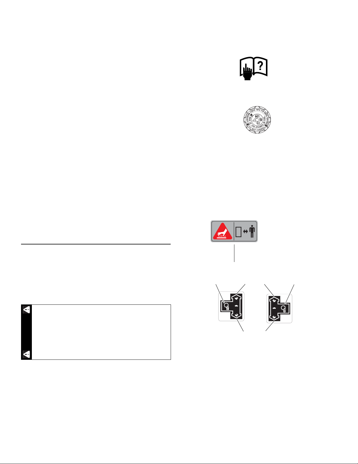
The following illustrations show the safety decals that are
located on the mower. A brief explanation is shown to help
the operator understand the decal’s meaning.
• Read Operator’s Manual and Safety Warning Decals before
attempting to operate this machine.
• Do not smoke while refueling.
• Do not remove the fuel tank cap or fill tank with engine running or
while the engine is hot.
• Allow engine to cool before storing machine inside a building.
• Store away from open flame or spark if there is fuel in tank.
• Clean up any gasoline spills.
• Do not refuel while in enclosed trailer or other enclosed areas.
• Maximum of 10% ethanol (E10) in fuel. Fuels with greater than 10%
ethanol, (such as E15, E20 and E85) voids warranty. Fuels with
greater than 10% ethanol are not approved for use and such illegal
use could cause equipment failure and pose a fire hazard.
Safety and Instructions Decals
The decals are designed to give the operator and mechanic
brief daily operational and service information. Use these
decals as an extension of this manual. Do not remove or
obliterate the decals. Replace unreadable or missing decals.
It is the owner’s responsibility to make certain that the
operators and mechanics read and understand all decals
before operating this machine.
Specific safety warning decals are located on the
equipment near the immediate areas of potential
hazards. Do not remove or obliterate these decals.
Replace them if they become non-readable.
Part Number 602041
WARNING:
• Keep a safe distance from the machine.
Hot surface!
Part Number 785139 & 785220
REV A 2-6 607233
Page 13
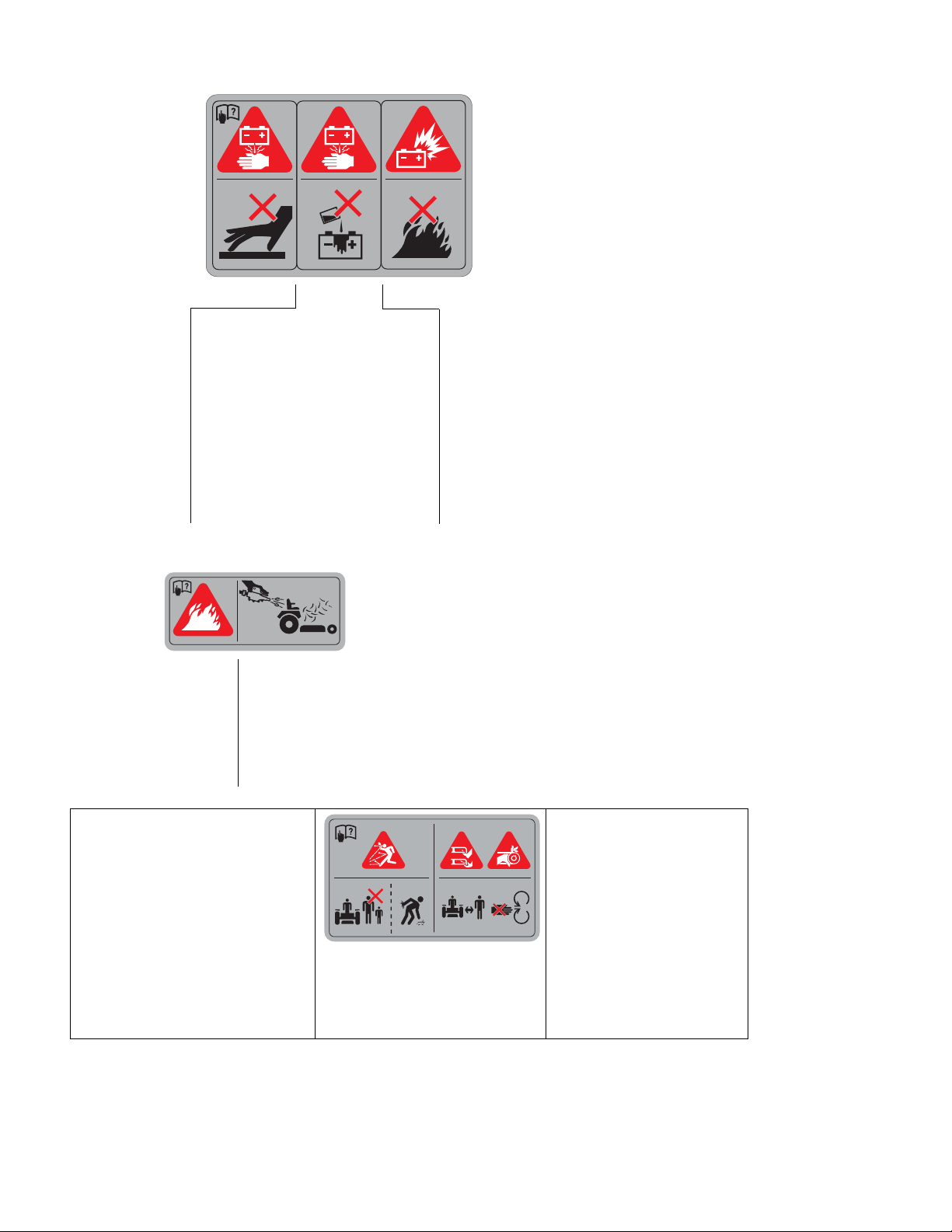
601815
601967
Part Number 601815
• Do not overfill battery.
• Electrolyte may overflow and damage
paint, wiring or structure. When cleaning
the battery, use soap and water. Be
careful not to get soap and water into the
battery. Use soda mixed in water to
clean corrosion off the terminals.
• Always wear eye protection when
checking the battery, acid can cause
serious injury to skin and eyes. If contact
occurs, flush area with clean water and
call physician immediately. Acid will also
damage clothing.
• Avoid skin contact
with battery acid
• Do not allow open flame near the
battery when charging.
• Hydrogen gas forms inside the
battery. This gas is both toxic and
flammable and may cause an
explosion if exposed to flame.
Always remove the negative ground
first and replace it last.
604222
DANGER: Battery Hazards!
WARNING: Fire!
Part Number 601967
WARNING: Thrown objects!
• Always maintain a safe distance from
people and pets when mowing.
• Always stop machine if someone enters
the area.
• Inspect area to be mowed for hazards
such as rocks, metal objects and other
debris which may be thrown or entangled
by mower blades. Remove these objects
before mowing.
607233 2-7 REV A
• Clean flammable material from
machine. Prevent fires by keeping
engine compartment, top of deck,
exhaust area, battery, fuel line, fuel
tank and operator’s station clean of
accumulated trash, grass clippings,
and other debris. Always clean up
spilled fuel and oil.
Part Number 604222
DANGER:
Rotating blades, pulleys & belts
• Keep shields and covers in place
while machine is in operation.
• Keep hands, feet and clothing
away from rotating pulleys and
belts.
Page 14
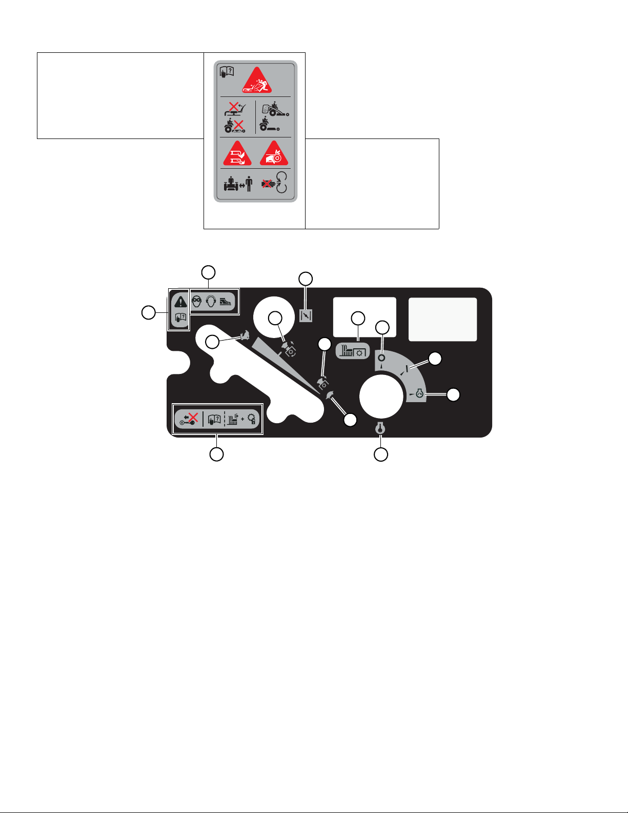
604889
Part Number 604889
C
M
D
F
L
B
G
H
E
J
I
A
K
WARNING: Thrown objects!
604221
• Never operate the mower deck with side
deflector damaged, altered, removed or in
raised position, except when the entire
grass catcher attachment or mulching
system is being used.
Part Number 604221
DANGER:
Rotating blades, pulleys & belts
• Keep shields and covers in place
while machine is in operation.
• Keep hands, feet and clothing
away from rotating pulleys and
belts.
A. Fast
B. Slow
C. Choke
D. Mower blade engage/disengage switch
E. Ignition switch - insert key
F. OFF
G. ON
H. Engine start position
I. Wear ear protection, eye protection and safety shoes
when operating this equipment.
J. Read Operator’s Manual before attempting to operate
this machine.
K. Before starting the engine:
• Read Owner’s Manual
• Disengage mower blades
• Place control levers in park brake position
L. For maximum electric clutch life engage at 1/2 - 3/4
throttle position.
M. For maximum electric clutch life disengage at low
throttle position.
REV A 2-8 607233
Page 15

1. Hold this sheet of paper in front of you. Make sure that Line A is horizontal.
2. Align Line B with a vertical surface such as pole, tree or building.
3. Fold the paper along the slope guide lines (C, D or E).
4. Align the closest slope guide line with the ground slope. This will give you a close estimation of the ground slope to
be mowed.
Slope Guide Lines
Line B
D (10o)
C (5o)
E (15o)
Line A
Slope Guide
Use this diagram when determining the degree of slope to be mowed.
607233 2-9 REV A
Page 16

REV A 2-10 607233
Page 17
OPERATION
D
A
B
C
WARNING
A
Safe Operating Practices
Refer to the Safety Precautions section of this manual for
operational and personal safety information.
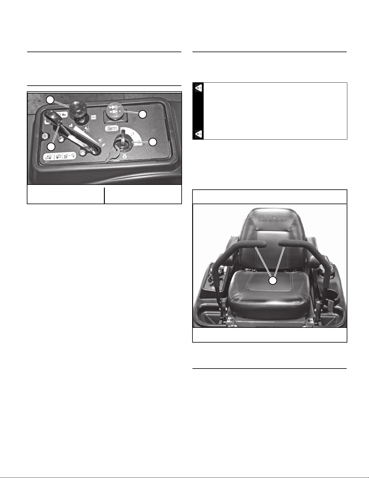
Control Panel
A. Deck clutch switch
B. Ignition switch
C. Throttle
D. Choke
Figure 3-1
Controls
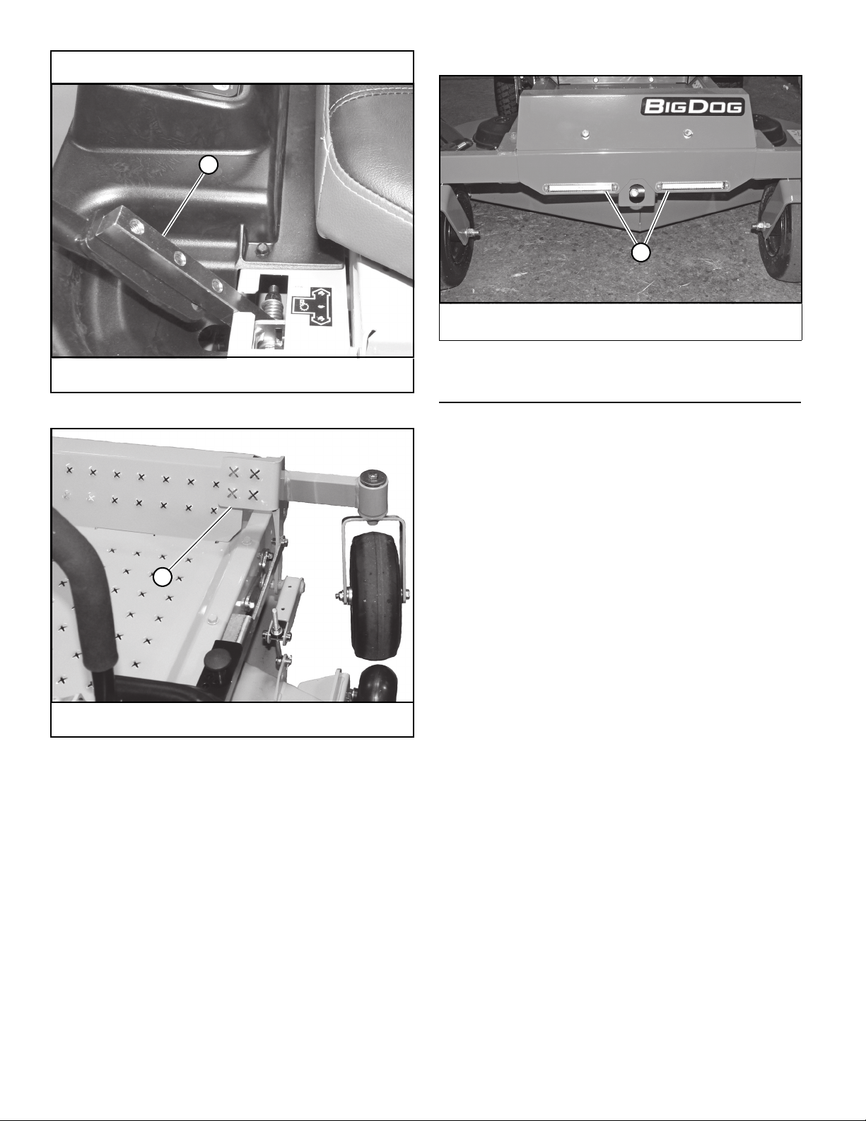
A. Steering control levers (Figure 3-2 & Figure 3-3) —
these levers control the mower’s speed, direction,
stopping, and park brake.
The parking brake may not hold the mower if
parked on a slope. Block or chock the machine
when parked on a slope.
B. Deck lift pedal (Figure 3-4) — the deck lift pedal is
used to raise or lower the deck. Push on the pedal to
raise the deck and then place the adjusting pin into the
desired cutting height hole. Release the pedal. Push
the deck lift pedal to raise the deck when going over
obstructions.
Shown with steering control levers in the neutral position
A. Deck clutch switch (Figure 3-1) — this switch engages
the deck. Pull the switch up to engage and push the
switch down to disengage the clutch.
For additional clutch information refer to the Mower
Deck Operation section of this manual.
B. Ignition switch (Figure 3-1) — a three position switch:
“OFF”, “RUN”, and “START”. With the key inserted,
rotate it clockwise to the “START” position; release the
key when the engine starts, and the switch will automatically return to the “RUN” position
C. Throttle control (Figure 3-1) — a cable is linked to the
engine throttle for controlling engine speed. Move the
lever forward to increase engine rpm, move the lever
rearward to decrease engine rpm.
D. Choke control (Figure 3-1) — a cable is linked to manu-
ally operate the engine choke. When the lever is in the
down position, the choke is in the “OFF” (run) position.
When the knob is pulled up, the choke is in the “ON”
(start) position. Do not operate the machine in the “ON”
(start) position.
A. Steering control lever
Figure 3-2
Lights
These mowers come equipped with operating lights
mounted in the front mower frame. There is no dedicated
“ON/OFF” switch for these lights. These lights come on when
the ignition switch is in the “RUN” position and go off when
the ignition switch is in the “OFF” position. Figure 3-5
607233 3-1 REV A
Page 18
Shown with steering control lever in the park brake position
A
A
A
A. Lights
Figure 3-5
A. Steering control lever
A. Deck lift pedal
Figure 3-3
Figure 3-4
Safety Start Interlock System
The mower’s safety start interlock system consists of the
park brake switches, seat switch, and deck clutch switch.
IMPORTANT: Repair this important safety feature
immediately if it malfunctions.
This safety feature prevents mower runaway or accidental
entanglement during operation.
Check the mower’s safety start interlock system daily,
prior to operation.
To inspect the system:
1. Sit on the seat when testing the seat switch.
2. Set both steering control levers in the park brake
position.
3. Start the engine and allow it to warm up to operating
temperature.
4. With the deck clutch switch down and the steering
control levers in the park brake position, slowly rise off
of the seat. The engine should continue to run.
5. With the deck clutch switch up and/or the steering
control levers in the neutral position, slowly rise off of
the seat. The engine should stop.
6. If the engine fails to stop when:
• the deck clutch switch is up, or
• one or both of the steering control levers is in the
up (out of neutral position), and
• the operator is off the seat, then
• check the function of the seat switch. Replace
the seat switch if it is not operating properly (is
not opening or closing) and if the cause can not
be determined.
REV A 3-2 607233
Page 19

If you cannot locate the problem contact your BigDog
WARNING
WARNING
WARNING
Mower Dealer.
The safety interlock system should always
function per steps 4 and 5. If it does not function
properly, correct it immediately. Do not operate
machine without a properly functioning seat
safety switch.
®
An interval of at least two minutes should be allowed
between such cranking periods to protect the starter
from overheating and burn-out.
6. Perform test to make sure safety start interlock
system is operating properly. Refer to Safety Start
Interlock System section.
7. Allow the engine to idle a few minutes before
advancing the throttle and/or engaging the deck
clutch.
Starting the Engine
The mower’s safety start interlock system is also designed
to protect the operator and others from accidental injury due
to unintentional engine starting. The engine starting motor
will not engage until:
1. Steering control levers are in the park brake position.
2. Deck clutch switch is in the down (OFF) position.
The safety interlock system must not be
disconnected or bypassed. Doing so could cause the
machine to operate unexpectedly resulting in
personal injury.
NOTE: The operator’s seat is equipped with a separate
safety switch. If for any reason the operator should become
unseated when the steering control levers are not in the park
brake position (park brake switches are disengaged) or the
deck clutch switch is engaged the engine will stop.
The following steps are the correct procedures for starting
the engine. If difficulty is encountered, contact the BigDog
Mowers Dealer in your area.
1. Before starting mower each day, perform daily preoperation checking. (See Safety Start Interlock System
section.)
2. Make sure the steering control levers are in the park
brake position and deck clutch switch is disengaged.
Only start the engine from the operator’s position.
3. Use the choke, if the unit is equipped with one, when
engine is cold, or if warm engine fails to start within 5
seconds of cranking. Avoid flooding and operate
engine without choking as soon as possible.
4. Set throttle at approximately 1/2 open position.
5. Insert key in ignition switch and rotate full clockwise
to engage starting motor. Release key when engine
starts.
IMPORTANT: The engine starter should not be
operated for periods longer than 30 seconds at a time.
Stopping the Engine
Use the following procedure to shut the engine off.
1. Place the steering control levers in the park brake
position.
2. Throttle the engine back to low idle, then disengage
the deck clutch. Refer to the Mower Deck Operation
section for more details.
3. Let the engine run at low idle for two minutes.
4. Rotate the ignition key counter-clockwise to the “OFF”
position. Remove the key from the switch before
leaving the mower.
Moving the Mower With Stalled Engine
The bypass valves on the transaxles allow the mower to be
moved if the engine quits working.
Allow the engine exhaust manifold to cool before
engaging or disengaging the bypass valves. The
bypass valve rods are located close to the exhaust
system.
®
Before moving the unit, pull out on the bypass valve rod
(Figure 3-6) until the notch in the rod hooks over the edge of
the slot. This places the bypass valves in the disengaged
position.
Place the steering control levers in the neutral position, to
release the park brakes, so that the mower can be moved.
Do not tow the machine. Move it by hand or use a winch to
load onto a trailer for transporting.
Secure the mower, facing forward, when transporting on
another vehicle. Tie the mower down securely using straps,
chains, cables, or ropes. Both front and rear straps should be
directed down and outward from the machine.
IMPORTANT: Always make certain the two bypass valves
are returned to their operating position before running the
mower following repairs.
607233 3-3 REV A
Page 20
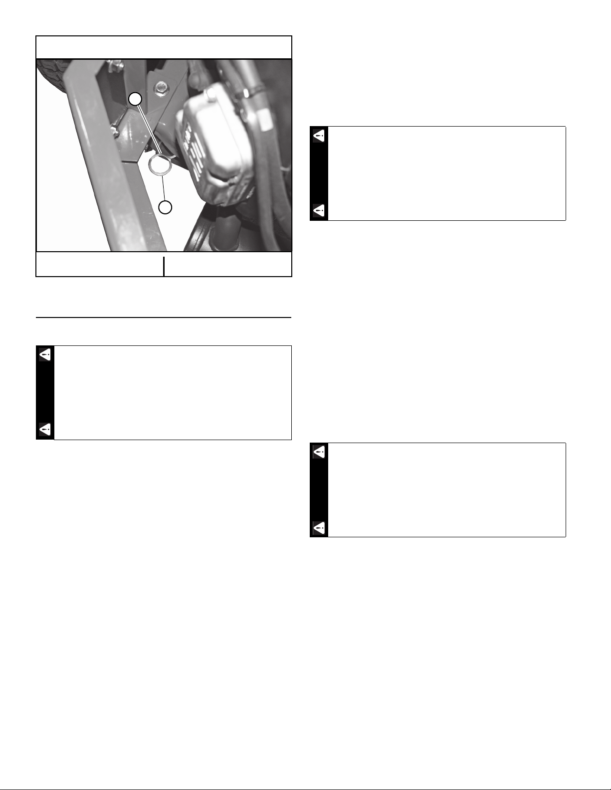
Bypass valve rod shown in operating position
A
B
DANGER
DANGER
WARNING
A. Bypass valve rod B. Slot
Figure 3-6
Mower Operation
Driving the Mower
Never make sudden stops or reverse direction,
especially when maneuvering on a slope. The
steering is designed for sensitive response. Rapid
movement of the control levers in either direction
could result in a reaction of the mower that can
cause serious injury.
To stop or decrease speed, move steering control levers to
neutral. When going forward pull back gently on steering
control levers. When going in reverse push forward gently on
steering control levers.
For emergency stops, when traveling forward or rearward,
place the steering control levers in the park brake position
immediately.
When moving in the rearward direction push
forward gently on steering control levers and avoid
sudden movement. Any sudden movement could
cause the front of the mower to come off of the
ground resulting in possible loss of control,
causing serious injury or death.
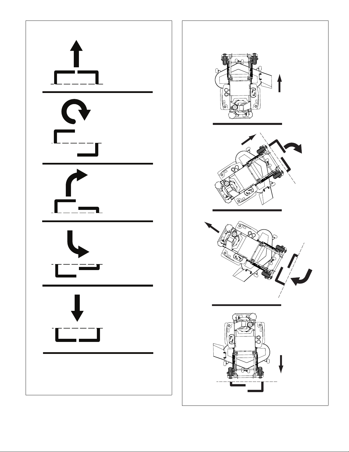
To make a three point turn to the right:
1. Move the left steering control lever farther forward
from neutral than the right steering control lever and
start the turn. Figure 3-8
2. Next, pull back on the steering control levers until they
pass neutral and the machine starts to go rearward.
Figure 3-8
3. Pull the right steering control lever farther rearward
from neutral than the left steering control lever until
the rear of the machine pivots around. Figure 3-8
4. Then, push the steering control levers forward until
they both pass neutral and the machine starts to go
forward. Figure 3-8
5. Push the left steering control lever farther forward
from neutral than the right steering control lever and
finish the turn. Figure 3-8
After starting the engine, engage the steering control
levers and steer as follows:
To go forward, push the steering control levers forward an
equal distance. Figure 3-7
To go in reverse, pull the steering control levers rearward
an equal distance. Figure 3-7
To turn left, move the right steering control lever farther
forward from neutral than the left steering control lever.
To turn right, move the left steering control lever farther
forward from neutral than the right steering control lever.
Figure 3-7
Zero radius turn, move one steering control lever forward
and the other steering control lever back of neutral. This
allows the drive wheels to counter-rotate. Figure 3-7
Always be aware of what is behind the machine
before backing up. Do not mow in reverse unless
absolutely necessary. Always look down and
behind before and while backing up.
IMPORTANT: Damage to the hydraulic system
components may occur with rapid movement of the steering
controls.
To increase speed, increase the steering control lever’s
distance from neutral. The farther forward the steering
control levers are from neutral, the faster the mower will
travel forward. The farther back the steering control levers
are from neutral, the faster the mower will go in reverse.
REV A 3-4 607233
Page 21
FORWARD TRAVEL
FRONT OF MOWER FACES THIS DIRECTION
ZERO RADIUS TURN
FORWARD TRAVEL
RIGHT TURN
REVERSE TRAVEL
RIGHT TURN
REVERSE TRAVEL
N = NEUTRAL POSITION
Direction of arrows indicate direction of mower
movement
N
N
N
N
N
N
N
N
N
N
Step 1
THREE POINT TURN
Step 2
Step 3
R
i
g
h
t
c
o
n
tro
l
l
ev
er
L
e
f
t
c
o
n
t
ro
l
l
ev
er
N
e
u
t
r
a
l
R
i
g
h
t
c
o
n
t
r
o
l
l
e
v
e
r
L
e
f
t
c
o
n
t
r
o
l
l
e
v
e
r
N
e
u
t
r
a
l
Neutral
Left control leverRight control lever
Figure 3-7
607233 3-5 REV A
Figure 3-8
Page 22

Operating Suggestions
DANGER
WARNING
WARNING
WARNING
DANGER
WARNING
An inexperienced operator should not mow on
slopes or on uneven terrain.
Before attempting normal speed operation an
inexperienced operator should:
• be thoroughly familiar with the proper use
and operation of the equipment.
• read the manual completely and thoroughly.
• have attempted slow moving maneuvers.
If you lose steering control while operating the
machine, place the steering control levers in the park
brake position immediately. Inspect the machine and
involve your BigDog
problem before continuing to operate.
The unit’s steering control levers are very
responsive: Easy does it! For smooth operation,
move the levers slowly, avoiding sudden
movement. Skill and ease of operation come with
practice and experience. The machine can spin
very rapidly. Use caution when making turns and
slow down before making sharp turns.
Inexperienced operators may have a tendency to oversteer
and lose control. Practice slow maneuvers at low engine rpm
(idle) on a flat open area before attempting normal speed
operation.
Sharp depressions or raised obstacles (such as
gutters or curbs) should not be directly
approached at high speed in an attempt to “jump”
them as the operator could be thrown from the
equipment. Approach at a slow speed and angle
one drive wheel at the obstruction. Continue at an
angle until the wheel clears and then pivot the
opposite wheel around.
When turning on soft wet turf, keep both wheels rolling
either forward or backward. Pivoting on one stopped wheel
can damage turf, especially when mowing.
Set the throttle at full rpm for maximum performance. This
gives maximum power to the drive wheels and deck when
needed. The throttle setting directly controls blade speed.
Use the control levers to control ground speed rather than
engine rpm.
Keep blades sharp. Many problems with incorrect cutting
patterns are due to dull blades or blades which have been
sharpened incorrectly. Information on sharpening blades is
listed in this manual’s maintenance section. Blade sharpness
should be checked daily.
®
Mower Dealer to resolve the
Never work with blades while the engine is running
or deck clutch switch is engaged (on).
Always place the deck clutch switch in the
disengaged position, place steering control levers
in the park brake position, turn the engine off and
disconnect the negative battery cable.
Block the mower up when you must work under it.
Wear gloves when handling blades.
Always check for blade damage if the mower
strikes a rock, branch or other foreign object
during mowing!
Direct grass discharge to the right, away from the
unmowed area. Generally, this means using a pattern of left
turns. Avoid throwing grass discharge onto unmowed area.
Mowing clippings puts an unnecessary load on the unit and
reduces mowing efficiency.
When mowing a lawn for the first time cut grass slightly
longer than normal to avoid scalping uneven terrain. When
cutting grass taller than six inches, you may want to mow the
lawn twice to achieve a better quality of cut.
During normal mowing cut only about 1/3 of the grass
blade.
Alternate the mowing direction to keep the grass growing
straight and for better dispersion of the clippings.
Remember, grass grows at different rates at different
times of the year. Mow more often in the early spring to
maintain the same cutting height. As the growth rate slows
in midsummer, mow less frequently. If you cannot mow at a
regular interval, mow at a high cutting height; then mow
again two days later at a lower cutting height.
Raise the cutting height of the mower if the cutting width
of the mower is wider than the previous mower. This ensures
that uneven turf is not cut too short.
Raise the cutting height of the mower if the grass is
slightly taller than normal or if it contains a high degree of
moisture. Then mow it again with the cutting height set
lower.
If the machine’s forward motion must be stopped while
mowing, a clump of grass clippings may drop onto your lawn.
To avoid this, move onto a previously cut area with the
blades engaged.
Never direct the discharge of material from the
mower deck toward bystanders.
• Never operate the mower deck with the
discharge chute damaged, altered, removed,
or in the raised position, except when the
entire grass catcher attachment or mulching
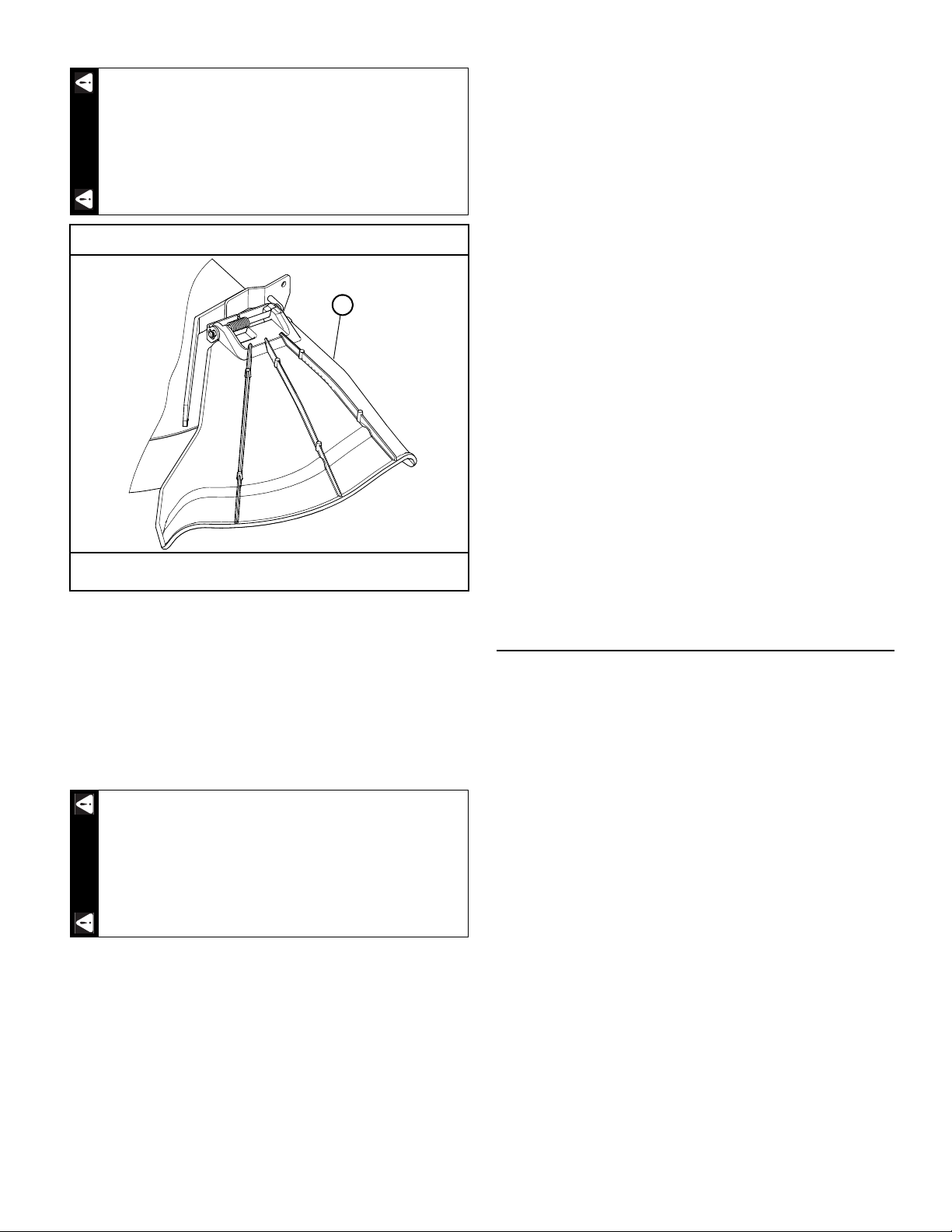
system is being used. Figure 3-9
REV A 3-6 607233
Page 23
A
DANGER
WARNING
Never attempt to make any adjustments to the
mower deck while the engine is running or with the
deck drive clutch engaged. Mower blades cannot
be seen and are located very close to the deck
housing. Fingers and toes can be cut off instantly.
Discharge chute may vary from this illustration
A. Discharge chute
Figure 3-9
Flex Forks
®
New Flex Forks® require a brief break-in period. Refer to the
Maintenance and Adjustments section of this manual for more
details.
Deck Clutch Operation
Before beginning operation, check to make sure the deck
clutch switch is engaging and disengaging the blades properly.
Make sure that the area around and under the deck
is clear and that there are no bystanders in the
immediate area before proceeding.
To check the deck clutch switch:
1. Start the engine and engage the deck clutch.
2. With the deck clutch switch up (clutch engaged) and
the engine running, listen to confirm that the mower
blades are rotating.
3. Now, push the deck clutch switch down (clutch
disengaged), and with the engine running, listen to
confirm that the blades have stopped rotating.
4. If the mower blades continue to rotate with the deck
clutch switch down, discontinue operation
immediately and contact your BigDog
®
Mower Dealer.
Follow these procedures to maximize clutch life.
1. Engage the clutch only under the following conditions:
• throttle set at approximately 2/3 as shown on
instrument panel;
• deck cutting height set to Notch D or higher;
•no load on the blades.
After clutch engagement, adjust the deck cutting height
to the desired level, if necessary, and advance the engine
throttle to full rpm.
IMPORTANT: Engaging the deck clutch at high engine
rpm, low deck heights or when under heavy load (in tall
grass, for example) can cause belts and/or electric
clutch to slip, resulting in premature wear or possible
damage.
2. Disengage the clutch only when the throttle is set at
less than 1/2 throttle.
Never disengage the clutch with the engine running at
high rpm. Setting the throttle to less than 1/2 throttle
when disengaging the clutch will help extend clutch life.
Warranty will not be allowed for deck clutches that fail due
to improper engagement and disengagement practices.
Deck Cutting Height Adjustment
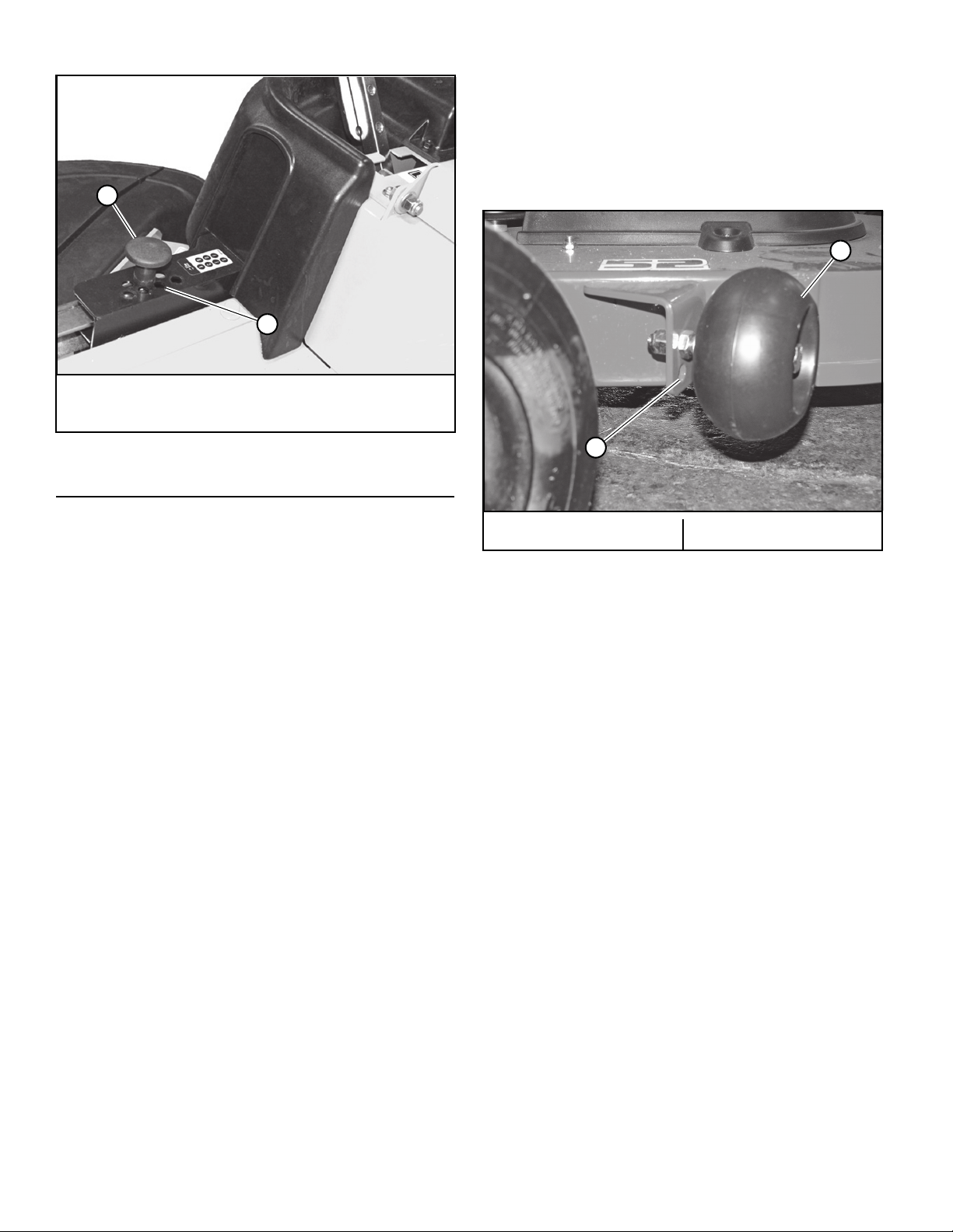
The deck cutting height is adjustable in 1/2" (12.7 mm)
increments. The holes in the height adjusting plate are
spaced at 1/2" (12.7mm) intervals. Figure 3-10
To set the deck cutting height:
1. Push on the deck lift pedal to release pressure from
the cutting height pin. Figure 3-10
2. Place the pin in the desired cutting height hole.
Figure 3-10
3. Release the deck lift pedal.
To place the deck in the transport position:
1. Push on the deck lift pedal until the transport lever pin
slips into the slot in the top of the height adjusting bar.
Figure 3-10
2. Release the deck lift pedal.
To release the deck from the transport position:
1. Push on the deck lift pedal.
2. Pull on the transport lever handle until the transport
lever pin lifts out of the slot. Figure 3-10
Release the deck lift pedal to lower the deck to the desired
cutting height.
607233 3-7 REV A
Page 24
A
B
A
B
A. Deck cutting height pin
B. Cutting height holes
Anti-scalp Wheels
1.60” (40.6mm) below the mower blades. This setting is
preferred when mowing at cutting heights of 2-1/2” (63.5mm)
or higher.
When the wheel is mounted in the top hole, it is located .70”
(17.8mm) below the mower blades. This is the acceptable
setting for mowing at cutting heights of 1-1/2” (38.1mm) or
higher.
Figure 3-10
Anti-scalp wheels are standard on these mowers. These
wheels are designed to minimize scalping when mowing on
rough uneven terrain. Figure 3-11
Anti-scalp wheels can be installed in two positions. With
the wheel installed in the bottom hole, the wheel is located
A. Anti-scalp wheel B. Adjusting holes
Figure 3-11
REV A 3-8 607233
Page 25

MAINTENANCE & ADJUSTMENTS
WARNING
DANGER
Safe Servicing Practices
Refer to the Safety Precautions section of this manual for
more service safety information.
Service Introduction
Regular maintenance is the best prevention for costly
downtime or expensive, premature repair. The following
pages contain suggested maintenance information and
schedules which the operator should follow on a routine
basis. For more detailed information order the correct Parts
Manual and General Service Manual for your unit. Refer to the
Product Literature section of this manual.
Remain alert for unusual noises, which could signal a
problem. Visually inspect the machine for any abnormal wear
or damage. A good time to detect potential problems is while
performing scheduled maintenance service. Correcting the
problem as quickly as possible is the best insurance.
Clear away heavy build-up of grease, oil and dirt, especially
in the engine and under the seat platform areas; minute dust
particle are abrasive to close-tolerance engine and hydraulic
assemblies.
Inspect mower daily for grass clippings and wire or string
tangles. The underside of the mower deck will collect a buildup of grass clippings and dirt, especially when grass is wet or
has high moisture content. This build-up will harden,
restricting blade and air movement and will probably show a
poorer quality of cutting. Therefore it should be removed
routinely.
To do this it will be necessary to raise and block the deck
using jack stands or blocks in the full up position. Scrape the
build-up from underneath.
IMPORTANT: Seat arm rests – Place the steering control
levers in the park brake position and pivot the arm rests
upward before lifting the seat platform to prevent arm rest
damage.
Some repairs require the assistance of a trained service
mechanic and should not be attempted by unskilled
personnel. Consult your BigDog
when assistance is needed.
®
Mowers service center
Torque Values
Particular attention must be given to tightening
the drive wheel lug nuts and blade spindle bolts.
Failure to correctly torque these items may result
in the loss of a wheel or blade, which can cause
serious damage or personal injury.
Torque values are given below:
ft-lbs N•m
Wheel (lug) nuts . . . . . . . . . . . . . . . . . 70 . . . . . . . . . 95
Blade spindle bolt top. . . . . . . . . . . . . 60 . . . . . . . . . 81
Blade spindle bolt bottom . . . . . . . . . 48 . . . . . . . . . 65
Lug nuts only - It is recommended that these be checked
after the first 2 hours of operation, initially, every 40 hours
and following removal for repair or replacement.
For all other torques refer to the mower’s General Service
Manual for standard torque chart. See the Product Literature
section for ordering information.
For engine torque values, refer to the engine owner’s
manual.
Tires
It is important for level mowing that the tires have the
same amount of air pressure. The recommended pressures
are:
Drive wheels . . . . . . . . . . . . . . . . . . 8–12 psi (55–83 KPa)
Front wheels . . . . . . . . . . . . . . . . . . 8–12 psi (55–83 KPa)
Only pneumatic tires are approved for use on this mower.
Warranty claims will be denied on any mower equipped with
non-pneumatic tires.
Flex Fork® Break-In
Flex Forks® may raise the front of the mower
approximately 1" when first installed. It is not necessary to
re-level the deck at this time. Drive the mower for
approximately 20 minutes, stop the mower and check to see
if the deck is level. If adjustment is required, refer to the
mower’s General Service Manual for deck leveling
procedures.
Never attempt to make any adjustments to the
mower deck while the engine is running or with the
deck drive clutch engaged. Mower blades cannot
be seen and are located very close to the deck
housing. Fingers and toes can be cut off instantly.
607233 4-1 REV A
Page 26
Lubrication
A
WARNING
WARNING
Use SAE multi-purpose grease.
Electrical System
IMPORTANT: Refer to the Safety section of this manual for
detailed battery servicing safety information.
The electrical system is a 12 volt, negative ground. The
recommended battery size is:
Garden tractor BCI group U1R with a 225 or better
cranking AMP rating.
A maintenance-free battery is recommended. Otherwise,
follow battery manufacturer’s maintenance, safety, storing
and charging specifications.
Master In-Line Fuse
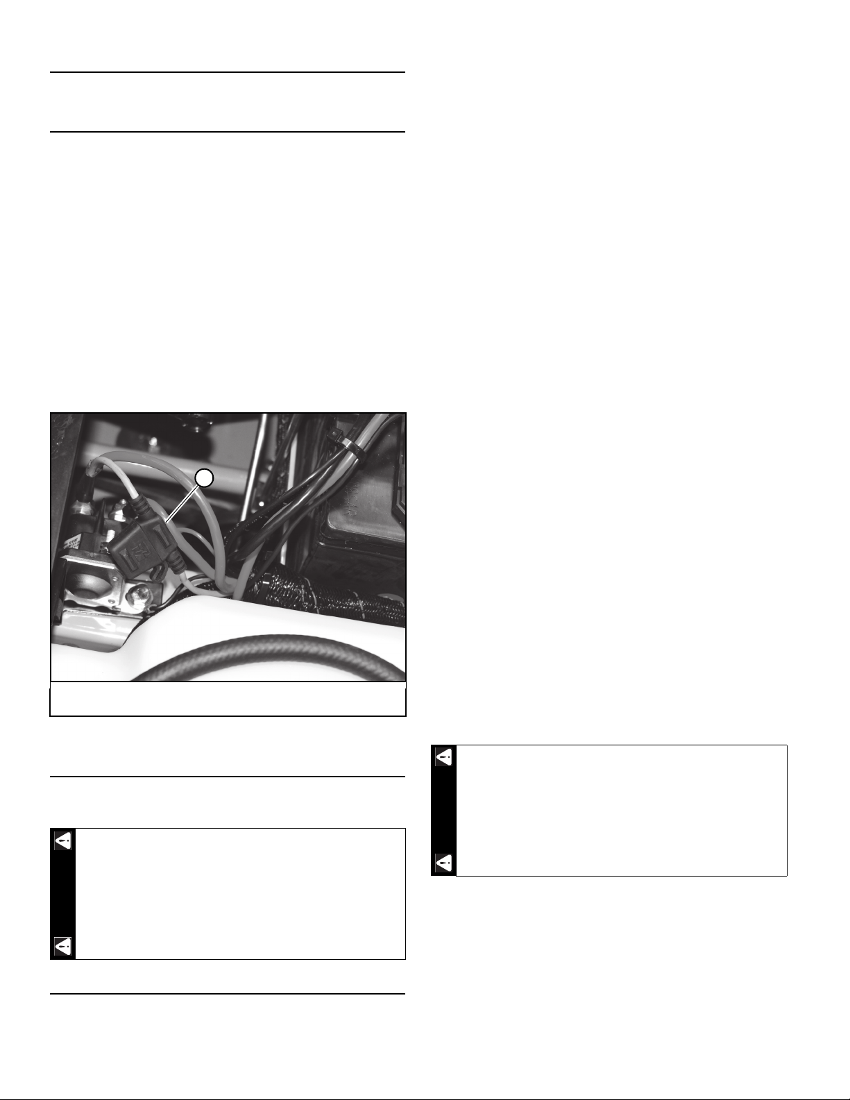
These mowers have a master in-line fuse in the electrical
system. This is the main fuse to protect the complete
electrical system. It is located under the seat platform and
next to the solenoid. Figure 4-1
A. Master fuse housing
Figure 4-1
The fuel and evaporative emissions control system for this
mower is EPA compliant. Use only BigDog
®
Mower approved
replacement parts.
Your evaporative emission control system may include
parts such as:
• fuel tanks
• fuel lines
• fuel line fittings
• fuel caps
• carbon canisters
• canister mounting brackets
• carburetor purge port connection
• filters
• vapor hoses
• clamps, control valves
• control solenoids
• electronic controls
• vacuum control diaphragms
• purge valves
• liquid/vapor separator
• other associated components
Modifying or Tampering with the evaporative emissions
control system or the fuel system is prohibited. Federal law
and California State law prohibit the following acts or the
causing thereof:
1. The removal or rendering inoperative by any person
other than for purposes of maintenance, repair,
replacement, of any device or element of design
incorporated into any equipment for the purposes of
emissions control prior to or after its sales or delivery
to the ultimate purchaser or while it is in use, or
2. The use of the equipment after such device or element
of design has been removed or rendered inoperative by
any person.
Hydraulic System
The transmissions are sealed for life and do not require
any scheduled maintenance.
When washing the mower, direct the spray away
(especially if using a power washer) from the
transaxle’s seals to prevent water intrusion and
ensure component performance.
Fuel and Evaporative Emissions Control System
filler neck and fuel cap located in the left side fender.
Figure 4-2
cap. Remove the fuel cap slowly.
IMPORTANT: Refer to the Safety section of this manual for
fuel handling safety information.
cap until it begins to click, then, continue to turn it until at
least three clicks are heard.
REV A 4-2 607233
Use of replacement parts not equivalent to the
original parts may result in system failure and
pose a safety hazard.
The fuel tank is located under the seat platform with the
Park the mower on level ground before filling fuel tank.
Clean the area around the fuel cap before removing the
When threading the fuel cap onto the filler neck, tighten the
Page 27
A
WARNING
A
Fill to the bottom of the filler neck
Maximum
Do Not
Overfill
B
A
WARNING
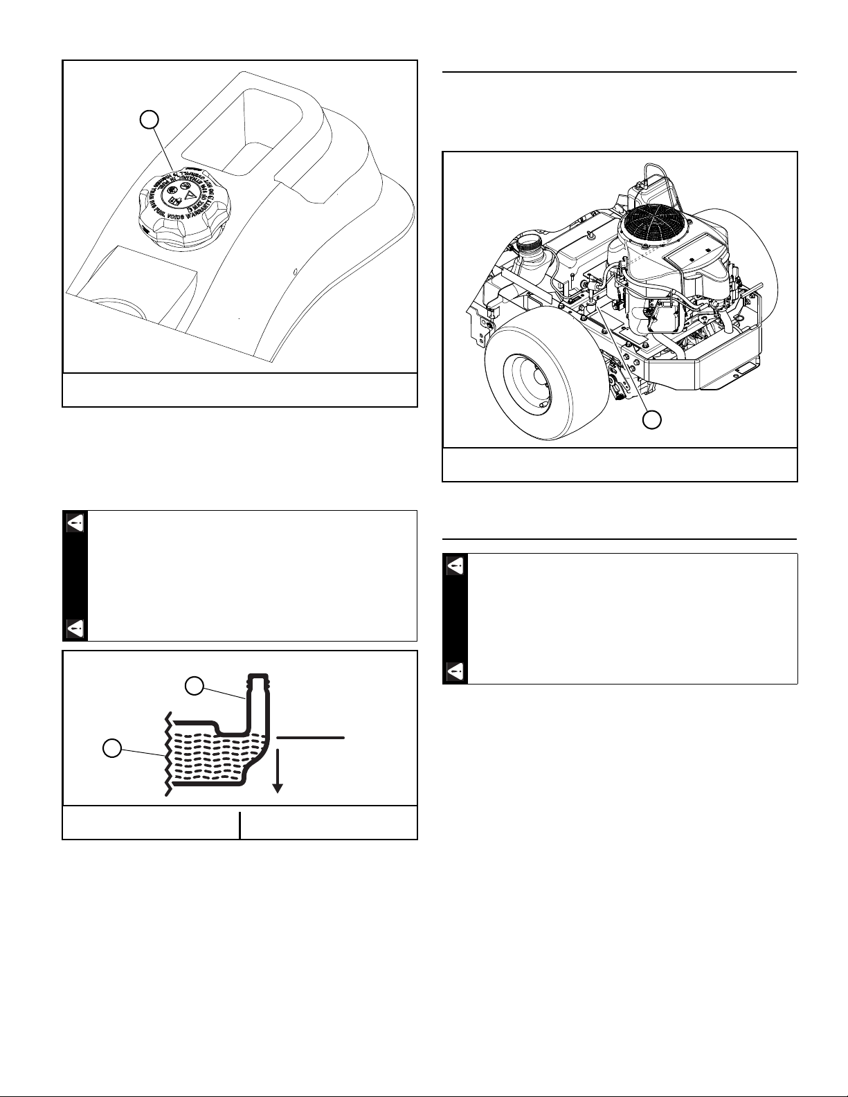
A. Fuel cap
Figure 4-2
IMPORTANT: Do not overfill the fuel tank. The fuel tank
should be filled
no higher than the bottom of the fill neck. The
fuel system is designed to leave room for the fuel to expand
with fuel temperature changes. Figure 4-3
Fuel Evaporation System Filter
These mowers have a fuel evaporation system filter. This
filter must be checked and replaced every 100 hours or
annually whichever comes first. Figure 4-4
A. Fuel evaporation system filter
Figure 4-4
or higher. Maximum of 10% ethanol (E10) in fuel. Fuels with
greater than 10% ethanol (such as E15, E20 and E85) voids
warranty. Fuels with greater than 10% ethanol are not
approved for use and such illegal use could cause equipment
failure and pose a fire hazard.
specification requirements.
607233 4-3 REV A
Overfilling the fuel tank may cause the following:
• Engine damage
• Fire hazard!
A. Filler neck B. Fuel tank
Figure 4-3
Use regular unleaded gasoline with an octane rating of 87
Refer to the Engine Owner’s Manual for additional fuel
Engine Oil and Filter
If the engine has been running and is up to operating
temperature, allow the engine to cool before
changing the oil. Engine and engine oil will be very
hot, so be very careful when changing oil and wear
the appropriate protective gear to avoid being
burned or exposed to engine oil.
Check engine oil daily and after every 4 hours of operation.
Mower must be on a level surface when checking oil. Refer to
engine manual and maintenance schedule for oil
recommendation and capacities.
Change the engine oil and filter after the first 5 hours of
operation and then per the engine manufacturer’s
recommendations after that. If mower is being operated in
extremely dirty conditions, then it is recommended oil be
changed more frequently.
IMPORTANT: After the new oil filter has been installed,
clean up any oil which may have spilled onto the engine plate
and exhaust system.
Draining the engine oil:
1. Locate the oil drain valve on the lower right side of the
engine.
2. Locate the oil drain hose that was supplied with the
machine. Be sure to clean and clear it of debris that
might block the flow of the engine oil. Figure 4-5
Page 28
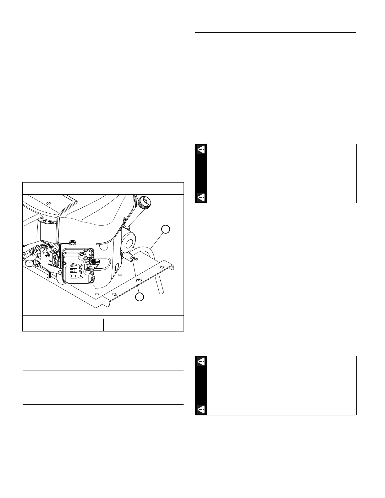
3. Attach one end of the hose onto the oil drain valve
A
B
WARNING
WARNING
nipple. Make sure the hose is pushed all the way onto
the valve. Figure 4-5
4. Position the loose end of the hose forward and down
in front of the right side transmission so that it can
drain into a suitable oil drain container.
5. With the hose in position, use a 10 mm wrench or
socket and open the valve approximately 4 turns in the
counterclockwise direction. Allow 10 minutes for
engine oil to adequately drain.
6. After oil is drained, close the valve by turning it in the
clockwise direction until it is fully closed.
7. Once the valve is closed, carefully remove the oil drain
hose and clean up any spilled oil.
IMPORTANT: All oil drips or spills must be cleaned off
of the engine plate and exhaust system before
operating the machine.
8. Clean the oil drain hose and store it appropriately.
Figure 4-5
Kawasaki engines
Belts
Inspect belts frequently for wear and serviceability.
Replace a belt that shows signs of:
• severe cuts
• tears
• separation
• weather checking
• cracking
• burns caused by slipping.
Slight raveling of belt covering does not indicate failure,
trim ravelings with a sharp knife.
If the pump belt fails, loss of control will occur
especially when operating on a slope. If you lose
steering control while operating the machine, place
the steering control levers in the park brake position
immediately. Inspect the machine and involve your
®
BigDog
continuing to operate.
Mower Dealer to resolve the problem before
A. Oil drain hose B. Oil drain valve
Figure 4-5
Engine Air Filter
Perform engine air filter maintenance per the Maintenance
Schedule shown elsewhere in this manual.
General Engine Maintenance
Inspect the belt pulley grooves and flanges for wear. A new
belt, or one in good condition, should never run against the
bottom of the groove. Replace the pulley when this is the
case, otherwise the belt will lose power and slip excessively.
Never pry a belt to get it on a pulley as this will cut or
damage the fibers of the belt covering.
Keep oil and grease away from belts, and never use belt
dressings. Any of these will destroy the belt composition in a
very short time.
Mower Blades
Mower Blade Maintenance
IMPORTANT: Refer to the Safety section of this manual for
blade handling safety information.
Refer to the Mower Blade Replacement section for blade
removal and installation.
Mower blades are sharp and can cut. Wrap the
blade(s) or wear gloves and use extra caution
when servicing them.
Detailed instructions and recommendations for break-in
and regular maintenance are specified in the Engine Owner’s
Manual. Please refer to this manual for engine servicing,
lubricating oil levels with quality and viscosity
recommendations, bolt torques, etc. The engine warranty is
backed by the engine manufacturer. Special attention should
be paid to applicable data which will not be duplicated here.
REV A 4-4 607233
Check the mower blades daily, they are the key to power
efficiency and well groomed turf. Keep the blades sharp. A
dull blade will tear rather than cut the grass, leaving a brown
ragged top on the grass within a few hours. A dull blade also
requires more power from the engine.
Replace any blade which is bent, cracked or broken.
Page 29
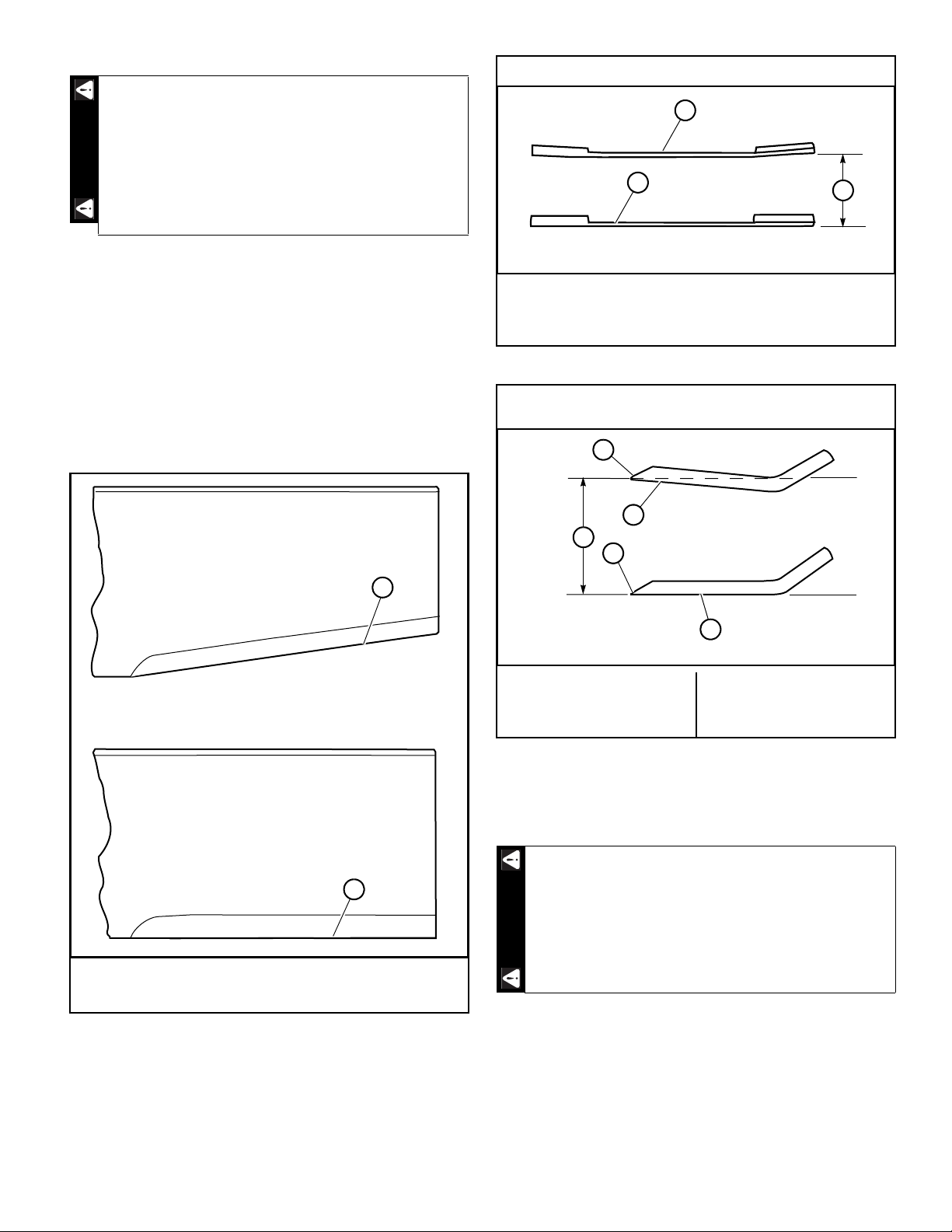
WARNING
Do not sharpen to original pattern (below). It is
easier to get a straight cutting edge following
the re-sharpening pattern shown above.
A
B
A
B
C
A
C
D
D
B
WARNING
Always check for blade damage:
• if mower strikes a rock, branch or other
foreign object during mowing!
• or if an abnormal vibration occurs while
operating.
Make all necessary repairs before resuming
operation.
Sharpen the blades following the pattern shown. Touch-up
sharpening can be done with a file. Figure 4-6
After grinding the blades, check for balance. Blade
balancing can be done by placing the blade on an inverted
line punch or 5/8" bolt. A commercial balancing tool is also
available through most hardware supply stores.
The blade should not lean or tilt. When spinning the blade
slowly it should not wobble. Balance the blade before
reinstalling.
Lay the blade on a flat surface and check for distortion.
Replace any distorted blade. Figure 4-7 & Figure 4-8
Comparison of Warped and Straight Blades
A. Warped blade — replace
B. Straight blade
C. Cutting plane
Figure 4-7
End view of blades, comparing twisted and straightened
blades.
A. Re-sharpening pattern
B. Original edge
Figure 4-6
A. Twisted blade edge —
replace blade
C. Cutting plane
D. Cutting edge
B. Straight blade edge
Figure 4-8
Mower Blade Replacement
IMPORTANT: Refer to the Safety section of this manual for
blade handling safety information.
Mower blades are sharp and can cut. Wrap the
blade(s) or wear gloves and use extra caution
when servicing them.
A 5/8" wrench is required to remove the 7/16" cap screw
holding the blade to the spindle shaft. NOTE: A blade holding
tool (part number 381442) is available from BigDog® Mower.
It is designed to prevent the blades from rotating when they
are being removed or installed on the spindle. Contact your
BigDog
®
Mower Dealer for more information.
607233 4-5 REV A
Page 30
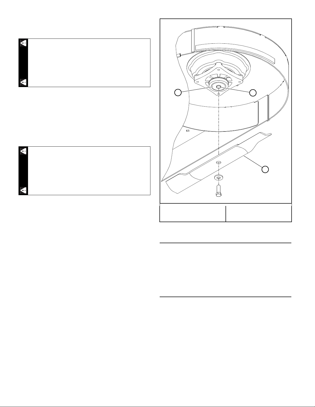
Do not re-use spindle bolts which have stripped, worn or
WARNING
WARNING
B
A
C
undercut threads. Torque bolts on spindles to 48 ft-lbs
(65 N•m) when reinstalling blades.
Failure to correctly torque the bolt may result in
the loss of the blade which can cause serious
injury.
IMPORTANT: The blade sail (curved part) must be
pointing upward toward the inside of the deck to ensure
proper cutting.
IMPORTANT: The spindles have 5/8" diameter boss that
centers the blades on the spindles. When re-installing blades,
ensure that the blade is centered on the boss and seated flat
against the spindle shaft face.
Rotate the blades after installation to ensure blade
tips do not touch each other or sides of the
mower.
A. Spindle shaft face
C. Blade
B. Boss
Figure 4-9
Seat Adjustment
The seat on the BigDog® Alpha® mower can be adjusted
forward and rearward by pivoting the seat platform up and
forward. Then, loosen the four cap screws on the underneath
side of the seat platform. Position the seat where you have
the best control of the machine and are the most
comfortable and then tighten the cap screws. Figure 4-10
Steering Control Lever Adjustment
The steering control levers can be adjusted for operator
comfort.
A. To pivot the upper control levers forward or rearward,
loosen the cap screws that attach the upper control
lever to the lower lever. Then, pivot the upper control
lever. Tighten the cap screws. Figure 4-11
B. To lower and raise the control levers, remove the cap
screws. Slide the upper control lever up or down and
align the holes with the holes in the lower lever. Reinstall the cap screws and tighten.
The steering control levers should be adjusted so that they
align with each other when in the neutral position.
REV A 4-6 607233
Page 31
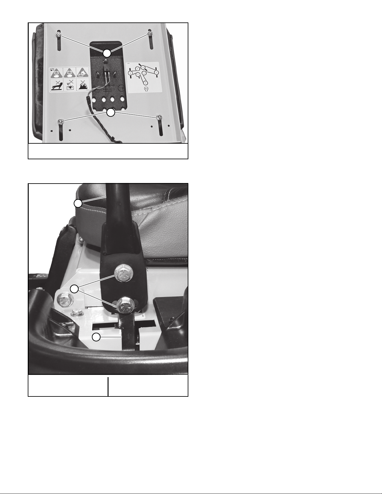
A. Cap screws
A
A
A
B
C
Figure 4-10
A. Upper control lever
C. Lower control lever
B. Cap screws
Figure 4-11
607233 4-7 REV A
Page 32

Maintenance Schedule
Refer to Figure 4-12, Figure 4-13, Figure 4-14,
Figure 4-15, & Figure 4-16
SERVICE AT
INTERVALS INDICATED
Verify safety start interlock system
Visually inspect unit for loose hardware and/or damaged parts
Visually inspect tires
Check oil level, engine (1)
Clean air intake screen (7)
Check fuel level
Blades - sharpen & securely fastened
Discharge chute - securely in place & in lowest position
Check tire pressure with a gauge
Clean engine and transmission compartment
Replace engine air cleaner element (4)(8)
Grease front wheel bearings
Change engine oil & filter (1)(3)
Clean cylinder and head fins (8)
Check battery connections
Clean engine exterior (8)
Tighten lug nuts on wheels (2)
Clean & regap spark plugs (8)
Check transmission & deck belt tension and condition (5)
Check fuel system (6)
Check fuel tank grommet (6)
Change fuel filter (6)
Replace fuel evaporation system filter (7)
Replace spark plugs (8)
WEEKLY
OR 40
HOURS
Prior to each use
Prior to each use
Prior to each use
Prior to each use or every 4 hours
Prior to each use or every 4 hours
Prior to each use
Prior to each use
Prior to each use
Prior to each use
After each use
X
X
X
X
X
X
* ANNUALLY
OR 100
HOURS
As needed
X
X
X
X
X
X
X
NOTES:
1. Initial engine oil change is after 5 hours of operation. Thereafter, change oil after every 40 hours operation. Change more often under dusty or
dirty conditions and during hot weather periods.
2. Torque initially and after first 2 hours of operation.
3. Change engine oil filter per the engine manufacturer’s recommendations. Refer to Engine Owner’s Manual for recommendations and other
maintenance items.
4. Service more often under dusty or dirty conditions. Use caution when servicing to prevent dust contamination in the engine. Do not clean filter
element. Replace with a new one.
5. Pump drive belt only - Inspect every month and replace if worn or cracking is noticed. Otherwise, replace every 2 years.
6. Check fuel system for any cracks or leaks including, but not limited to, fuel line hoses, fuel valve, vent line hoses, vent valve, vapor valve, carbon
canister, and grommets. Replace as needed.
7. More often under dusty or dirty conditions and during hot weather.
8. Refer to engine owner’s manual for engine service information.
* After completing maintenance cycle (100 hours), repeat cycle.
REV A 4-8 607233
Page 33
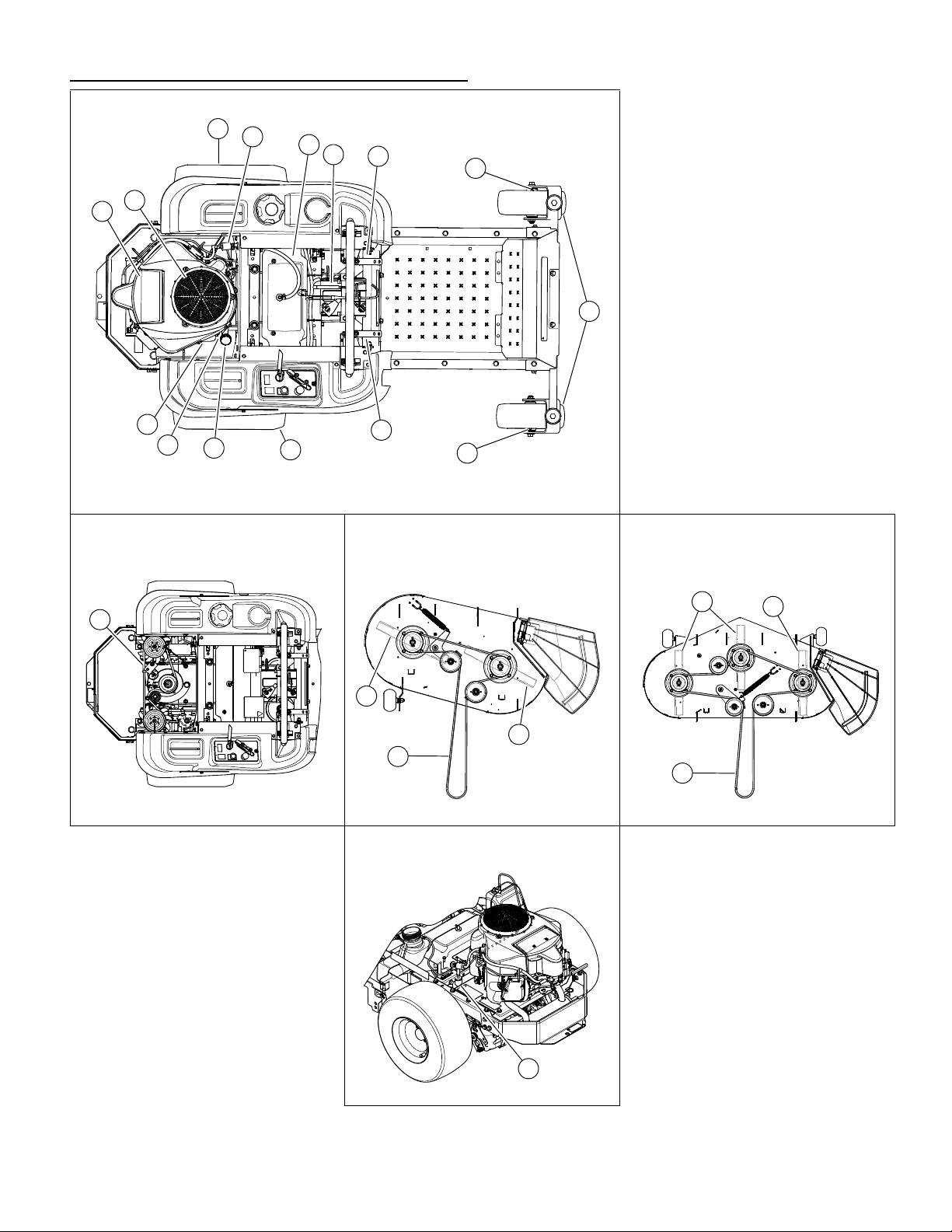
Maintenance Locator Chart
Figure 4-12
2
3
4
5
6
7
9
9
13
1
8
8
11
12
13
10
36”/42” Deck
15
15
14
52” Deck
15
15
14
16
1. Engine Oil Fill & Dipstick
2. Fuel Filter
3. Engine Air Cleaner
4. Engine Oil Drain Valve
5. Battery
6. Fuel Tank
7. Engine Oil Filter
8. Park Brake Switch (2)
9. Drive Tire
10. Pump Belt
11. Engine Air Intake Screen
12. Front Wheel Tires
13. Front Wheel Zerks (2)
14. Deck Belt
15. Blades
16. Fuel Evaporation System Filter
Figure 4-13 Figure 4-14 Figure 4-15
Figure 4-16
607233 4-9 REV A
Page 34

REV A 4-10 607233
Page 35

TROUBLESHOOTING
The majority of operating problems that occur with a system can be traced to improper adjustments or delayed service. A
consistently applied preventative maintenance program, as outlined in the Maintenance section of this manual, will prevent many
problems. The following chart is designed to help you locate a problem by suggesting probable causes and the recommended
solutions.
SYMPTOMS PROBABLE CAUSES
Starting motor does not
crank
The engine will not start,
starts hard or fails to
keep running
Engine:
Runs with continuous
misfiring or engine runs
unevenly or erratically
Loss of power or system
will not operate in either
direction
Air cooled engine
overheating
Low engine oil pressure Low oil level Add oil
High oil consumption Numerous Contact your Dealer
Mower jerky when
starting or operates in
one direction only
Steering control levers not
in park brake position or
switch not adjusted
Deck clutch switch
engaged
Weak or dead battery Recharge or replace
Electrical connections are
corroded or loose
15 amp fuse is blown Replace the 15 amp fuse
For additional causes See engine manual
No fuel or line plugged Fill tank or replace line
There is incorrect fuel in
the fuel system
There is dirt in the fuel filter Replace the fuel filter
Dirt, water or stale fuel in
the fuel system
The choke is not on
(if equipped)
Numerous See engine manual
Numerous See engine manual
Restrictions in air cleaner Service air cleaner
Poor compression Contact your Dealer
Steering linkage needs
adjustment
Tow valve open Close tow valve
The traction drive belt is
worn, loose or broken
For additional causes See engine manual
Air intake screen or cooling
fins clogged
For additional causes See engine manual
Oil diluted or too light Change oil and check for
Failed oil pump Contact your Dealer
Steering control linkage
needs adjustment
Loose steering linkage Tighten linkage
Transaxle component
faulty
SUGGESTED
REMEDIES
Place steering control
levers in park brake
position or re-adjust switch
Disengage clutch switch
Check the electrical
connections
(See Fuel System section
for more details)
Drain the tank and replace
the fuel with the proper
type
Contact your Dealer
Move the choke lever to ON
Adjust linkage
Install a new traction drive
belt
Clean screen and fins
source of contamination
Adjust linkage
Contact your Dealer
SYMPTOMS PROBABLE CAUSES
Mower creeps when
steering control levers are
in neutral
Mower circles or veers in
one direction
Mower creeps when
parking brake engaged
There is abnormal
vibration
Blades do not rotate The deck drive belt is worn,
Uneven cutting height The blade(s) are not sharp Sharpen the blades
Steering linkage needs
adjustment
Steering linkage needs
adjustment
Loose steering linkage Tighten linkage
Tires improperly inflated Adjust air pressure to 8–12
Transaxle component
faulty
Steering linkage out of
adjustment
Brakes need adjustment Adjust parking brakes
The engine mounting bolts
are loose
The engine pulley, idler
pulley or blade pulley is
loose
The engine pulley is
damaged
The cutting blade(s) is/are
bent or unbalanced
A blade mounting bolt is
loose
Spindle bearing is worn or
loose
A blade spindle is bent Contact your Dealer
loose or broken
The deck drive belt is off
the pulley
Electric clutch is not
engaging
A cutting blade(s) is/are
bent
The deck is not level Level the deck per the Deck
An anti-scalp wheel is not
set correctly
The underside of the deck
is dirty
Tires improperly inflated Adjust air pressure to 8–12
A blade spindle is bent Contact your Dealer
Flex Forks® are installed
SUGGESTED
REMEDIES
Adjust linkage
Adjust linkage
psi (55–83 KPa)
Contact your Dealer
Adjust steering linkage
Tighten the engine
mounting bolts
Tighten the appropriate
pulley
Contact your Dealer
Install new cutting blade(s)
Tighten the blade
mounting bolt
Replace or tighten spindle
bearing
Install a new deck drive
belt
Install the deck drive belt
and check for a reason
Check and/or replace 15
amp fuse.
Contact your Dealer
Install new cutting blade(s)
leveling section of the
General Service Manual
Adjust the height of the
anti-scalp wheel
Clean the underside of the
deck
psi (55–83 KPa)
After initial break-in period,
level the deck per the Deck
Leveling section of the
General Service Manual
607233 5-1 REV A
Page 36

REV A 5-2 607233
Page 37

General Mower Preparation for Storage
WARNING
WARNING
WARNING
STORAGE
1. Remove all grass, dirt, and trash from mower and
cutting units.
IMPORTANT: Wash the machine with a mild detergent
and water. Do not pressure wash the machine. Avoid
excessive use of water, especially near the control
panel and engine.
2. Clean mower and deck and touch up all scrapes with
touch-up paint.
3. Install new air filter per Engine Owner’s Manual.
4. Check thoroughly for any worn or damaged parts that
need replacing and order them from your dealer.
5. Thoroughly lubricate machine, according to the
Maintenance section.
6. Block mower up so weight is off tires. Check tire
pressure and inflate to proper operating pressure.
NOTE: Do not deflate tires.
7. Perform separate engine and battery preparation as
listed below.
8. Store mower in a clean, dry place.
Preparation of Engine for Storage
If the mower is to be unused for an extended period of time
(30 days or more), the engine will need to be prepared for
storage. Use the following procedures before storing the
mower.
IMPORTANT: Refer to the Fuel Handling Precautions
section of this manual for important safety information
before proceeding.
1. Add a BigDog
fuel system. Refer to the instructions shown on the
fuel stabilizer bottle for proper usage. For detailed
information consult with your Dealer.
2. Fill the fuel tank(s) with fresh fuel.
NOTE: Use non-ethanol fuel if possible.
®
Mower approved fuel stabilizer to the
Allow the engine to cool before changing the
engine oil. Use caution when changing the engine
oil as it will be very hot. You should wear the
appropriate protective gear to avoid being burned
or exposed to engine oil.
7. Close the fuel shut-off valve (if equipped).
8. Check the oil filler cap and fuel tank cap(s) to make
certain they are securely in place.
9. Refer to the engine manual for more information.
Preparation of Battery for Storage
When the machine is to be unused for long periods, it is
best to disconnect the battery and remove it from the unit. At
this time perform the following battery maintenance:
1. Remove the battery from machine.
2. Clean the battery, terminals, and cable connectors.
3. Charge the battery, if necessary.
4. Store the battery in a cool, dry place (do not expose to
freezing temperatures).
5. Always keep the battery fully charged. Especially
important to prevent battery damage when the
temperature is below 32°F (0°C).
New Season Preparation
Before starting the mower following post season storage,
the following service is required:
1. Clean mower, removing trash and dirt accumulation.
2. Check engine oil level.
3. Install fully charged battery and attach the battery
cables.
4. Fill fuel tank(s) with fresh fuel. Run machine at half
speed for 5 minutes, checking operation of steering
control levers. Stop engine and check for oil leaks,
loose fittings and so forth.
607233 6-1 REV A
To prevent carbon monoxide poisoning, operate the
engine in a well ventilated area only.
3. Run the engine for a minimum of 10 minutes.
4. Drain the oil from the crankcase while the engine is
still warm.
5. Replace the engine oil filter.
6. Refill with fresh oil of the proper viscosity.
At start of new season always check that fresh
oilhas been added to machine. If oil is drained at
season’s end and not replaced, engine damage will
result.
5. Tighten any bolts that have loosened and make sure
all hair pins, cotter pins and clevis pins are in place.
6. Install all safety shields and review safety precautions
listed in this manual.
7. Check and inflate tires to 8–12 psi (55–83 KPa).
8. Refer to engine manual for more information.
Page 38

PRODUCT LITERATURE
If you would like to view or print a copy of the product manuals (Operator’s Manual, Parts Manual, or General Service Manual) for
these mowers go online to www.bigdogmowerco.com.
Contact your local BigDog
®
Mower dealer if you require another engine manual.
REV A 6-2 607233
Page 39

INDEX
PAGE PAGE
Air Flow Baffles .......................................................3-8
Anti-scalp Wheels
Battery Service Precautions
Belts
.........................................................................4-4
Children
...................................................................2-4
Cold Weather Pump Clutch
Control Panel
Controls
...................................................................3-1
Deck Clutch Operation
Deck Cutting Height Adjustment
Driving the Mower
Electrical System
Engine Air Filter
Engine Oil and Filter
Flex Forks
®
...................................................3-8
..................................2-5
....................................3-3
...........................................................3-1
............................................3-7
...........................3-7
...................................................3-4
....................................................4-2
......................................................4-4
...............................................4-3
..............................................................3-7
New Season Preparation
Operating Suggestions
Operation
................................................................2-2
Operator Platform Adjustment
Parts and Service
Personal Safety
................................................... 1-1
...................................................... 2-1
Possible Damage to ROPS
Preparation of Battery for Storage
Preparation of Engine for Storage
....................................... 6-1
.......................................... 3-6
............................. 4-7
.................................... 3-4
....................... 6-1
........................ 6-1
Raising the Deck to the Service Position
ROPS (Roll Over Protective Structure)
ROPS Inspection
Safe Operating Practices
Safe Operation
Safe Servicing Practices
.................................................... 3-4
...................................... 3-1
....................................................... 2-1
....................................... 4-1
................. 3-4
............. 3-4
Fuel & Evaporative Emissions Control System
Fuel Evaporation System Filter
Fuel Handling Precautions
Fuel Shut-off Valve
.................................................4-3
General Engine Maintenance
General Mower Preparation for Storage
Hydraulic System
Lights
.......................................................................3-1
Lubrication
....................................................4-2
..............................................................4-1
Maintenance Locator Chart
Maintenance Schedule
Master In-Line Fuse
...........................................4-7
................................................4-2
Model and Serial Number
Moving Mower with Stalled Engine
Mower Blade Maintenance
.............................4-3
....................................2-5
.................................4-4
...............6-1
...................................4-9
.......................................1-1
.......................3-3
....................................4-4
....4-2
Safety and Instructions Decals
Safety Start Interlock System
Seat Adjustment
Seat Belt Maintenance
Service Introduction
Service Precautions
Slope Guide
Slope Operation
Starting the Engine
.................................................... 4-6
.......................................... 3-4
.............................................. 4-1
............................................... 2-4
............................................................ 2-9
..................................................... 2-3
................................................ 3-2
Steering Control Lever Adjustment
Stopping the Engine
System Fuses
Tires
........................................................................ 4-1
To the New Owner
Torque Values
.............................................. 3-3
......................................................... 4-2
.................................................. 1-1
........................................................ 4-1
............................ 2-6
............................... 3-1
...................... 4-6
Mower Blade Maintenance Precautions
Mower Blade Replacement
Mower Blades
Mower Operation
607233 i-1 REV A
.........................................................4-4
....................................................3-4
....................................4-5
...............2-5
Using a Ramp
Using this Manual
......................................................... 2-3
.................................................. 1-1
Warranty Registration
........................................... 1-1
 Loading...