


PS
Biddle PS, PS-20, PS-41, PS-60, PS-61 Manual
...
Manual
Modular fan coil unit
Model PS
Version 2.1
07-2018
17-
Q P
English

B
Copyright
All the information and drawings in this manual are the property of Biddle and may not be
used (other than for the actual operation of
the device), photocopied, duplicated, translated and/or be brought to the attention of
third parties without Biddle’s prior written
permission.
The name Biddle is a registered trademark.
Trademarks
The name Biddle is a registered trademark of
Biddle bv.
Warranty and liability
Please refer to Biddle's Terms of Sales and
Delivery for warranty and liability conditions.
For more information
If you have any comments or questions
about specific topics relating to this product,
please do not hesitate to contact Biddle.
Addresses
United Kingdom
Biddle Air Systems Ltd.
St. Mary’s Road
Nuneaton
Warwickshire CV11 5AU
United Kingdom
telephone: 024 7638 4233
fax: 024 7637 3621
e-mail: sales@biddle-air.co.uk
internet: www.biddle-air.com
Biddle excludes liability for consequential
loss at all times and under all circumstances.
Liability for the contents of
this manual
However much care might have been taken
in ensuring the correctness and, where necessary, completeness of the description of
the relevant parts, Biddle disclaims all liability
for damage resulting from any inaccuracies
and/or deficiencies in this manual.
Should you detect any errors or ambiguities
in this manual then we would be pleased to
hear from you: it helps us to improve our
documentation even further.
Biddle retains the right to change the specifications stated in this manual.
Other countries
Biddle Export
PO Box 15
NL-9288 ZG Kootstertille
The Netherlands
telephone: +31 512 335555
fax: +31 512 335554
e-mail: export@biddle.nl
internet: www.biddle.info
2
Manual model PS

Modular fan coil unit Contents
2.7 Connecting the valve motor............ 12
Contents
2.8 Connecting ducts ............................ 12
2.9 Connecting the unit to the CH
1 Introduction ........................4
1.1 About this manual ............................. 4
1.2 How to use this manual .................... 4
1.2.1 Marginal symbols in the manual ......... 4
1.2.2 Pictograms used on the unit and in
the manual................................................... 4
1.2.3 Related documentation....................... 4
1.3 About the unit.................................... 5
1.3.1 Applications ........................................ 5
1.3.2 Working............................................... 5
1.3.3 Modules .............................................. 5
1.3.4 Type code ........................................... 6
1.3.5 Type plate ........................................... 6
and/or CW system ................................ 12
2.9.1 Water connections............................ 12
2.9.2 Frost protection................................. 13
2.9.3 Connecting water pipes .................... 13
2.10 Connecting the condensate drain. 13
2.10.1 Particulars....................................... 13
2.10.2 Connecting the condensate drain... 13
2.11 Connecting the unit to mains
power supply......................................... 14
2.11.1 General........................................... 14
2.11.2 Connecting to mains....................... 14
2.12 Installing the controller.................. 14
2.13 Switching on and checking
operation............................................... 14
1.4 Components ..................................... 6
1.4.1 Required components......................... 6
1.4.2 Accessories ........................................ 7
1.4.3 Parts not supplied............................... 7
1.5 Safety instructions ............................ 7
1.5.1 Operation............................................ 7
1.5.2 Installation, maintenance and
service ......................................................... 7
2 Installation..........................8
2.1 Safety instructions ............................ 8
3 Maintenance ....................16
3.1 Safety instructions .......................... 16
3.2 Replacing the filter .......................... 16
3.2.1 Introduction....................................... 16
3.2.2 Replacing flat-bed filter in base
module....................................................... 16
3.2.3 Replacing bag-type filter or pleated
filter............................................................ 16
3.3 Cleaning.......................................... 16
3.4 Scheduled maintenance ................. 16
2.2 Delivery check .................................. 8
2.3 General instructions.......................... 8
2.3.1 Order of working ................................. 8
2.3.2 Miscellaneous..................................... 8
2.4 Installing the wall duct ...................... 8
2.5 Installing the roof duct ...................... 9
2.6 Suspending the unit........................ 10
2.6.1 Positioning ........................................ 10
2.6.2 Installing the suspension rail............. 10
2.6.3 Suspending and securing modules....11
4 Service.............................18
4.1 Safety instructions .......................... 18
4.2 Opening the unit ............................. 18
4.2.1 Base module..................................... 18
4.2.2 Electronics compartment .................. 18
4.3 Fuses .............................................. 19
4.4 High-limit thermostat....................... 19
Version 2.1 English (17-07-2018)
3
B
1 Introduction
1.1 About this manual
d
Danger:
This indicates actions which are not permitted. Ignoring this warning may lead to
serious damage or accidents that may
involve physical injury.
This manual describes the installation and
maintenance of the modular fan coil unit,
model PS.
This manual only relates to the unit itself. A
separate manual covers the operation and
control of the unit.
1.2 How to use this manual
For unit
With ... module:
The description applies only to models that
have the feature referred to.
If no specific model is referred to, the description applies to all models.
1.2.2 Pictograms used on the unit and
in the manual
The below pictograms refer to possible risks
or dangers. These pictograms can also be
found on the unit.
ê
s with … :
w
Warning:
You are entering an area which
contains live components.
1.2.1 Marginal symbols in the manual
n
Note:
Draws your attention to an important part of
the text.
c
Caution:
If you do not carry out this procedure or
action correctly, you may damage the unit.
So, follow the instructions carefully.
w
Warning:
If you do not carry out this procedure or
action correctly, you may cause material
damage and/or physical injury.
So, follow the instructions carefully.
Accessible to qualified maintenance staff only. Caution is
urged.
ç
1.2.3 Related documentation
Besides this manual, the following documents come with the unit:
- documentation for control and operation
(if applicable);
- wiring diagram for installation and service purposes.
w
Warning:
This surface or part can be hot.
There is a risk of burns on contact.
4
Manual model PS
Modular fan coil unit 1 Introduction
1.3 About the unit
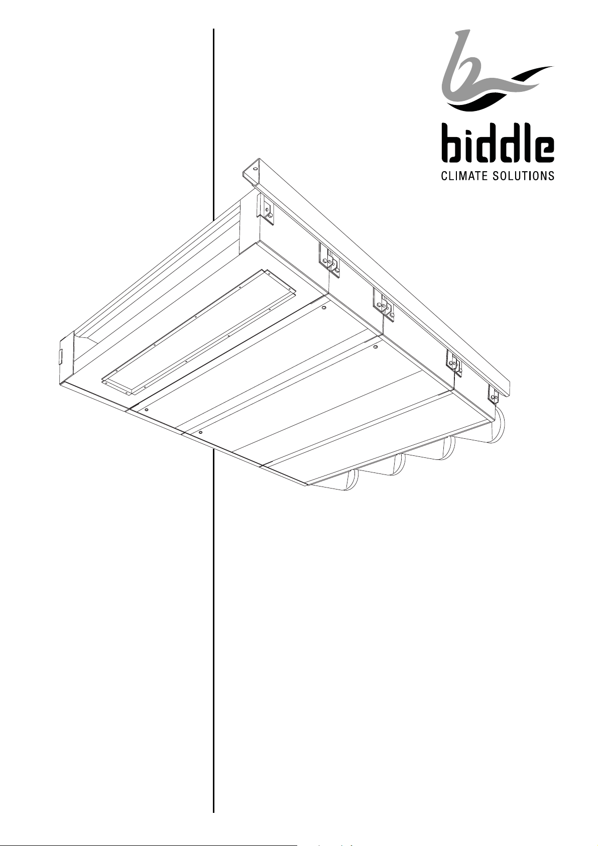
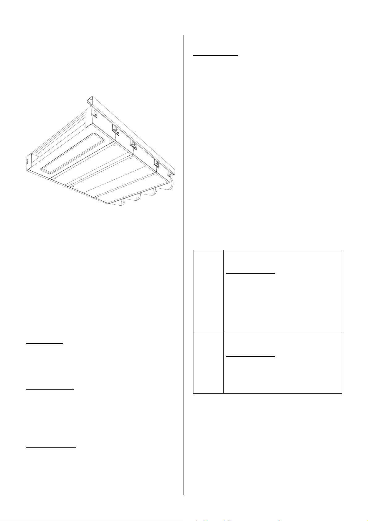
1.3.1 Applications
The modular fan coil unit is designed for
heating, cooling and/or ventilating rooms.
The inlets and outlets of the unit are positioned in such a way that the discharged air
flow is distributed evenly across the room
without causing discomfort to the people in it.
The unit’s dimensions are geared to integrating the unit in suspended ceilings.
1.3.2 Working
The fan coil unit blows a flow of air into the
room. The air may be taken in, at the user’s
option, either from outside (ventilation) or
from the room itself (recirculation). Thus, the
unit offers two benefits:
- The room is kept at the desired temperature.
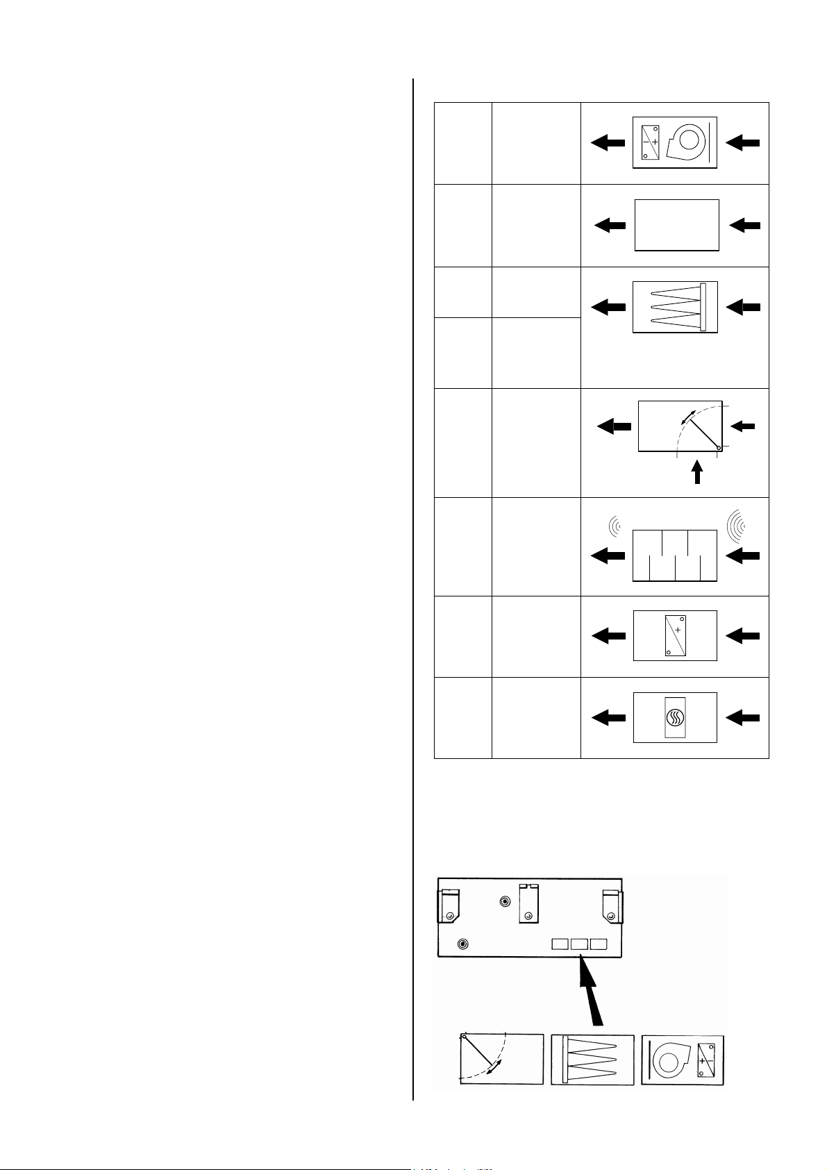
Type references and symbols of modules
PS B
PS P
PS F
PS FP
PS L
PS G
base
module
plenum
module
filter
module
pleated
filter
module
air valve
module
attenuation
module
- Gradual deterioration of air quality in the
room is counteracted.
1.3.3 Modules
A modular fan coil unit is made up of modules. Each module has its specific function.
By combining different modules, modular fan
coil units with different features can be composed.
PS V
PS VE
heating
module
(water)
heating
module
(electric)
The symbols can be found on the underside
of each module. On the base module, these
symbols indicate the order of the modules of
the delivered modular fan coil unit.
Version 2.1 English (17-07-2018)
5
B
1.3.4 Type code
The type references, when combined, constitute the type code of the unit's modules, for
instance:
PS B-20-H1-M
PS P-21
PS G-40
PS V-61-H1C3-I
Various combinations can be made.
Explanation of type code
series
module
capacity
with base
module and/or
heating module:
heating and/or
cooling
with base
module:
electronic
control
PS
B, P, F, FP,
L, G, V, VE
20, 21, 40,
41, 60, 61
H1, H2,
H3, H4
C3, C4
H1C3,
H2C2
HE
M
S
modular fan
coil unit
see Section
1.3.3
water heating
water cooling
water heating
and cooling
electric heating
modulating
control
speed control
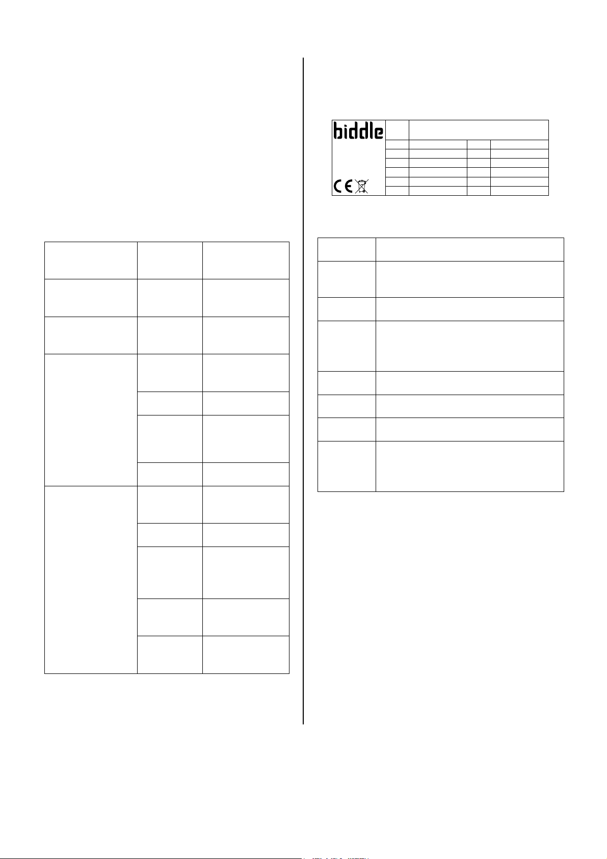
1.3.5 Type plate
The type plate is located on the base module.
Type PS B-40-H2-M
Biddle bv
Markowei 4
NL-9288 HA Kootstertille
Example of a type plate
References on the type plate
Type
Code
M
P
max
U
I
max
P
motor
P
heating
Code U 230 V ~ 50 Hz
4023
Nº 123456/1-1 07-12 I
M 51 kg I
Medium LPHW P
p
600 kPa P
max
max
I
max
max
motor
heating
L1 0.88 A
L2 -
L3 -
0.20 kW
-
full type code of unit
if applicable:
unit code of electronic control
weight of unit
with water heating:
maximum allowable operating
pressure
supply voltage
maximum amperage
maximum power absorbed by fans
with electric heating:
maximum power absorbed by heating
1.4 Components
6
I
B
without
reference
Interface, either
with or without
touch control
Basic, without
control
not described
in this manual
1.4.1 Required components
The following components are delivered
separately but are always required:
- mounting kit, consisting of a suspension
rail and fasteners for linking modules
- electronic control system components,
such as a controller, control cables, etc.
(see the documentation of the control
system)
Manual model PS
 Loading...